Embed Size (px)
Citation preview
Copyright® 1998Holset Engineering Co. Ltd.All rights reserved
Part No. 3580500Effect date 03.99
HX55VService Repair ManualProvided By: www.MyHolsetTurbo.com

ForewordThis publication was written to assist field personnel with basic overhaul and rebuilding of the Holset HX55Vturbocharger.
The specifications and rebuild information in this manual is based on information in effect at the time of printing. HolsetService reserves the right to make any changes at any time without obligation. If differences are found between yourturbocharger and the information in this manual, contact your local approved dealer.
The latest technology and the highest quality standards are used in the manufacture of Holset Turbochargers. Whenreplacement parts are needed, we recommend using only genuine Holset parts.
Advantages of Variable Geometry TurbochargersThe turbocharger on your vehicle’s engine is of a very advanced type, which changes the size of it’s turbine inresponse to the drivers demands. In this way, under all conditions of driving, the turbine through its electronic controls,changes the amount of air supplied to the engine, to ensure maximum performance, lowest fuel consumption andminimum exhaust emission levels..
During a (sudden) acceleration, the turbocharger will produce air for the engine much quicker than a convention unit,thus eliminating turbocharger lag and giving improved truck derivability
In addition, as the engine and turbocharger are run in , and eventually, start to wear, the combination of this variableturbine and its associated electronic control, will change its characteristic to keep to the original performance andemission levels over a wide rage of ambient temperatures and altitude
The bearing housing of your turbocharger contains an internal water-cooled jacket. The purpose of this is to reduce therunning temperature of the electronic speed probe and also to reduce the high temperatures produced when the engineis switched off after being heavily loaded.
The addition of this water cooling has meant that there are two extra pipe connections to the turbocharger, to bringwater to the housing and to take it away
It is important to observe the correct installation of these pipes, so that the circulation of the water is in the correctdirection, or the effectiveness of the cooling system will be lost and severe damage may result. The connections of thepipes into the bearing housing are sealed with and ‘o’ ring, and if the water connections to the housing are removed, anew ‘o’ ring seal must be used for re assembly.
provided by: www.MyHolsetTurbo.com

Table of ContentsIntroduction
General Information.....................................................................................................................................................4
About the Manual.........................................................................................................................................................4
How to Use the Manual ...............................................................................................................................................4
Fault Finding Chart ......................................................................................................................................................5
Symbols .......................................................................................................................................................................6
Component IdentificationTurbocharger Identification........................................................................................................................................11
Components ..............................................................................................................................................................12
Exploded View...........................................................................................................................................................13
Optional Components ................................................................................................................................................14
Actuator Inspection / Replacement............................................................................................................................15
Speed Probe Removal...............................................................................................................................................22
Component Disassembly and AssemblyService Tools .............................................................................................................................................................23
Disassembly ..............................................................................................................................................................24
Cleaning.....................................................................................................................................................................29
Inspection ..................................................................................................................................................................29
Assembly ...................................................................................................................................................................33
Installation Data.........................................................................................................................................................40
Installation Checklist ..................................................................................................................................................41
Table of ContentsPage 3
provided by: www.MyHolsetTurbo.com
IntroductionGeneral InformationA turbocharger is a mechanical device which uses the engine’s exhaust gases to force more air into the enginecylinders. A turbocharger uses energy from the engine to help increase its overall efficiency. Hot exhaust gas energy isused to turn a “shaft and wheel”. At the other end of the shaft is the “compressor impeller” (or compressor wheel),which draws in air and forces it into the engine cylinders.
Supplying increased air mass flow to the engine provides improved engine performance, lower exhaust smoke density,improved operating economy, altitude compensation, and noise reduction. The turbocharger has proven to be one of themost beneficial devices for improving engine performance. It performs its job very well, as long as it is properly cared for.
About the ManualThe procedures in this manual were developed to instruct in the correct overhaul of the Holset HX55V turbocharger toprovide for the optimum performance and minimum of maintenance operation.
How to Use the ManualThis manual is organised according to the steps needed to most easily and correctly overhaul the Holset HX55Vturbocharger. In the unlikely event of turbocharger malfunction, please check the Fault Finding Chart to identify potentialcauses, before attempting disassembly. To make sure of optimum performance, certain items must be discarded duringthe disassembly operation and replaced with new for re-assembly. These items are indicated in the disassembly sectionwith the use of a * symbol. All items showing a * are available in a basic HX55V overhaul kit. Contact your local agent forpart number and availability.
WarningThis turbocharger may have been manufactured using the ‘core balance’ process and therefore MUST be checkbalanced on rebuild.
A core balanced turbocharger will not have any co-relation marks on the thrust collar or oil slinger, and also may nothave co-relation marks on the end of the turbine shaft and impeller nose.
If you intend to overhaul/repair a core balanced turbocharger, and do not have access to a core balancing machine,we recommend that you make your own rotor co-relation marks during disassembly ( see appropriate illustration in thedisassembly section) with an indelible-ink pen, so that these parts can be reassembled in the same relative positions.
Please refer to the balance data section of this manual for the balance limits to be used for either core balancing orrotor balancing.
It is important to note that operating a turbocharger with a Rotor or Core balance level greater than the published limitscould cause turbocharger or engine failure. If you are in any doubt regarding the balancing process, please contact anapproved Holset distributor for assistance.
General InformationPage 4
Introduction
provided by: www.MyHolsetTurbo.com
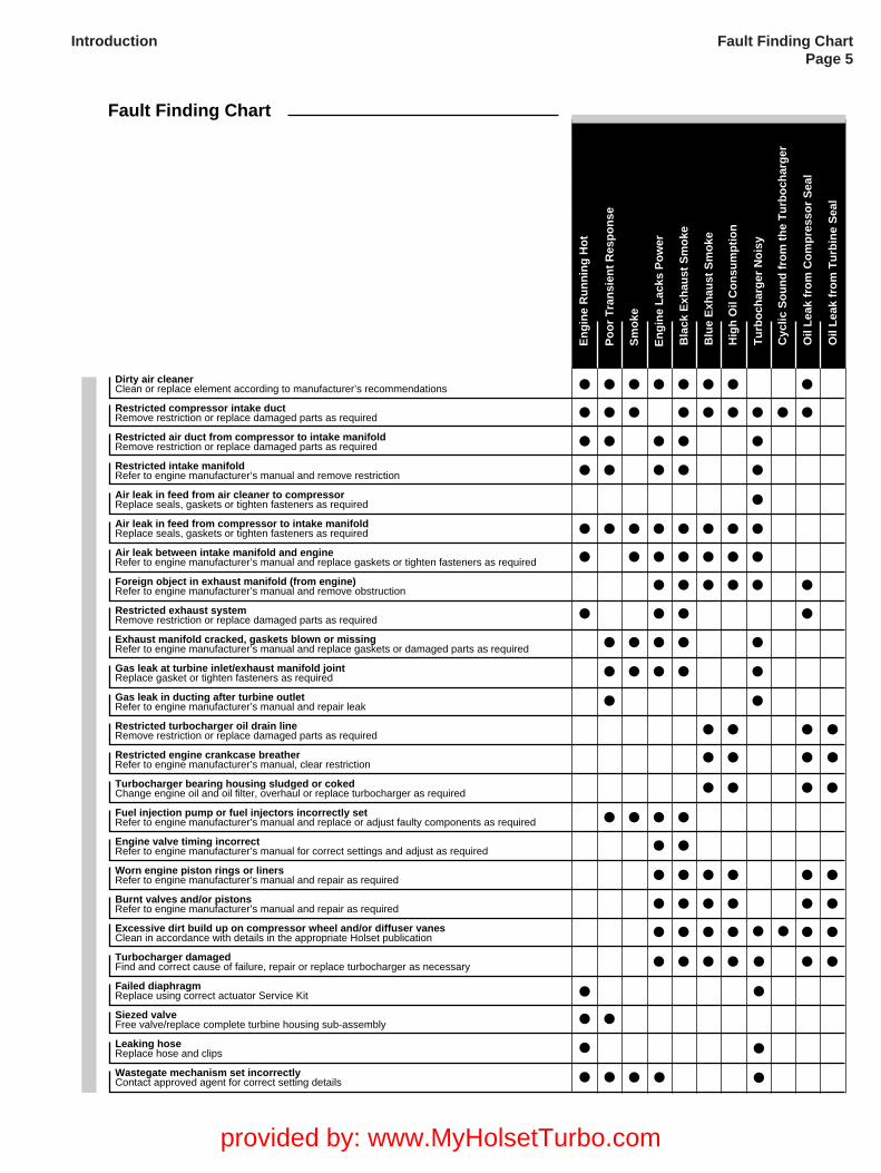
Fault Finding Chart
En
gin
e L
acks
Po
wer
Bla
ck E
xhau
st S
mo
ke
Blu
e E
xhau
st S
mo
ke
Hig
h O
il C
on
sum
pti
on
Tu
rbo
char
ger
No
isy
En
gin
e R
un
nin
g H
ot
Po
or
Tra
nsi
ent
Res
po
nse
Sm
oke
Cyc
lic S
ou
nd
fro
m t
he
Tu
rbo
char
ger
Oil
Lea
k fr
om
Co
mp
ress
or
Sea
l
Oil
Lea
k fr
om
Tu
rbin
e S
eal
Dirty air cleanerClean or replace element according to manufacturer’s recommendations
Restricted compressor intake ductRemove restriction or replace damaged parts as required
Restricted air duct from compressor to intake manifoldRemove restriction or replace damaged parts as required
Restricted intake manifoldRefer to engine manufacturer’s manual and remove restriction
Air leak in feed from air cleaner to compressorReplace seals, gaskets or tighten fasteners as required
Air leak in feed from compressor to intake manifoldReplace seals, gaskets or tighten fasteners as required
Air leak between intake manifold and engineRefer to engine manufacturer’s manual and replace gaskets or tighten fasteners as required
Foreign object in exhaust manifold (from engine)Refer to engine manufacturer’s manual and remove obstruction
Restricted exhaust systemRemove restriction or replace damaged parts as required
Exhaust manifold cracked, gaskets blown or missingRefer to engine manufacturer’s manual and replace gaskets or damaged parts as required
Gas leak at turbine inlet/exhaust manifold jointReplace gasket or tighten fasteners as required
Gas leak in ducting after turbine outletRefer to engine manufacturer’s manual and repair leak
Restricted turbocharger oil drain lineRemove restriction or replace damaged parts as required
Restricted engine crankcase breatherRefer to engine manufacturer’s manual, clear restriction
Turbocharger bearing housing sludged or cokedChange engine oil and oil filter, overhaul or replace turbocharger as required
Fuel injection pump or fuel injectors incorrectly setRefer to engine manufacturer’s manual and replace or adjust faulty components as required
Engine valve timing incorrectRefer to engine manufacturer’s manual for correct settings and adjust as required
Worn engine piston rings or linersRefer to engine manufacturer’s manual and repair as required
Burnt valves and/or pistonsRefer to engine manufacturer’s manual and repair as required
Excessive dirt build up on compressor wheel and/or diffuser vanesClean in accordance with details in the appropriate Holset publication
Turbocharger damagedFind and correct cause of failure, repair or replace turbocharger as necessary
Failed diaphragmReplace using correct actuator Service Kit
Siezed valveFree valve/replace complete turbine housing sub-assembly
Leaking hoseReplace hose and clips
Wastegate mechanism set incorrectlyContact approved agent for correct setting details
Fault Finding ChartPage 5
Introduction
provided by: www.MyHolsetTurbo.com

Symbols - EnglishThe following group of symbols have been used in this manual to help communicate the intent of the instructions. Whenone of the symbols appears, it conveys the meaning defined below.
WARNING - Serious personal injury or extensive property damage can result if the warning instructions arenot followed.
CAUTION - Minor personal injury can result or a part, an assembly or the engine can be damaged if thecaution instructions are not followed.
Indicates a REMOVAL or DISASSEMBLY step.
Indicates an INSTALLATION or ASSEMBLY step.
INSPECTION is required.
CLEAN the part or assembly.
PERFORM a mechanical or time MEASUREMENT.
LUBRICATE the part or assembly.
Indicates that a WRENCH or TOOL SIZE will be given.
TIGHTEN to a specific torque.
Ensure that the BALANCE MARKS on the rotor assembly are in alignment
PERFORM an electrical MEASUREMENT.
Refer to another location in this manual or another publication for additional information.
Please wear protective clothing at all times.
SymbolsPage 6
Introduction
provided by: www.MyHolsetTurbo.com
SymbolsPage 7
Introduction
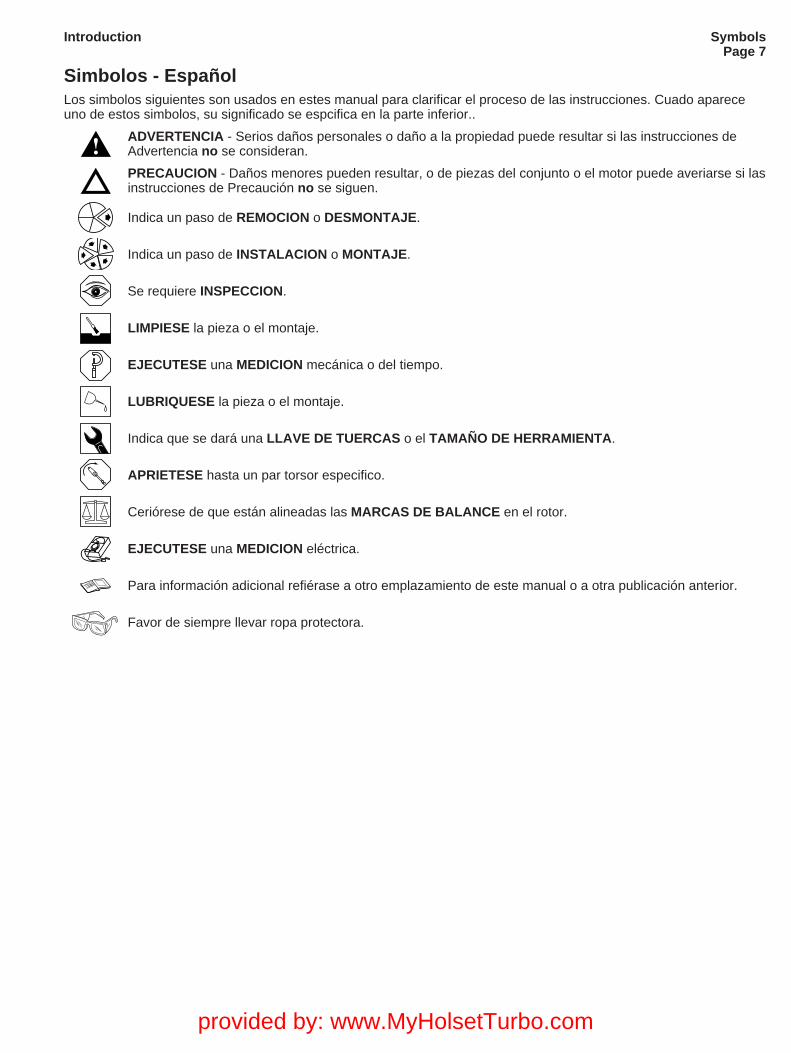
Simbolos - EspañolLos simbolos siguientes son usados en estes manual para clarificar el proceso de las instrucciones. Cuado apareceuno de estos simbolos, su significado se espcifica en la parte inferior..
ADVERTENCIA - Serios daños personales o daño a la propiedad puede resultar si las instrucciones deAdvertencia no se consideran.
PRECAUCION - Daños menores pueden resultar, o de piezas del conjunto o el motor puede averiarse si lasinstrucciones de Precaución no se siguen.
Indica un paso de REMOCION o DESMONTAJE.
Indica un paso de INSTALACION o MONTAJE.
Se requiere INSPECCION.
LIMPIESE la pieza o el montaje.
EJECUTESE una MEDICION mecánica o del tiempo.
LUBRIQUESE la pieza o el montaje.
Indica que se dará una LLAVE DE TUERCAS o el TAMAÑO DE HERRAMIENTA.
APRIETESE hasta un par torsor especifico.
Ceriórese de que están alineadas las MARCAS DE BALANCE en el rotor.
EJECUTESE una MEDICION eléctrica.
Para información adicional refiérase a otro emplazamiento de este manual o a otra publicación anterior.
Favor de siempre llevar ropa protectora.
provided by: www.MyHolsetTurbo.com
SymbolsPage 8
Introduction
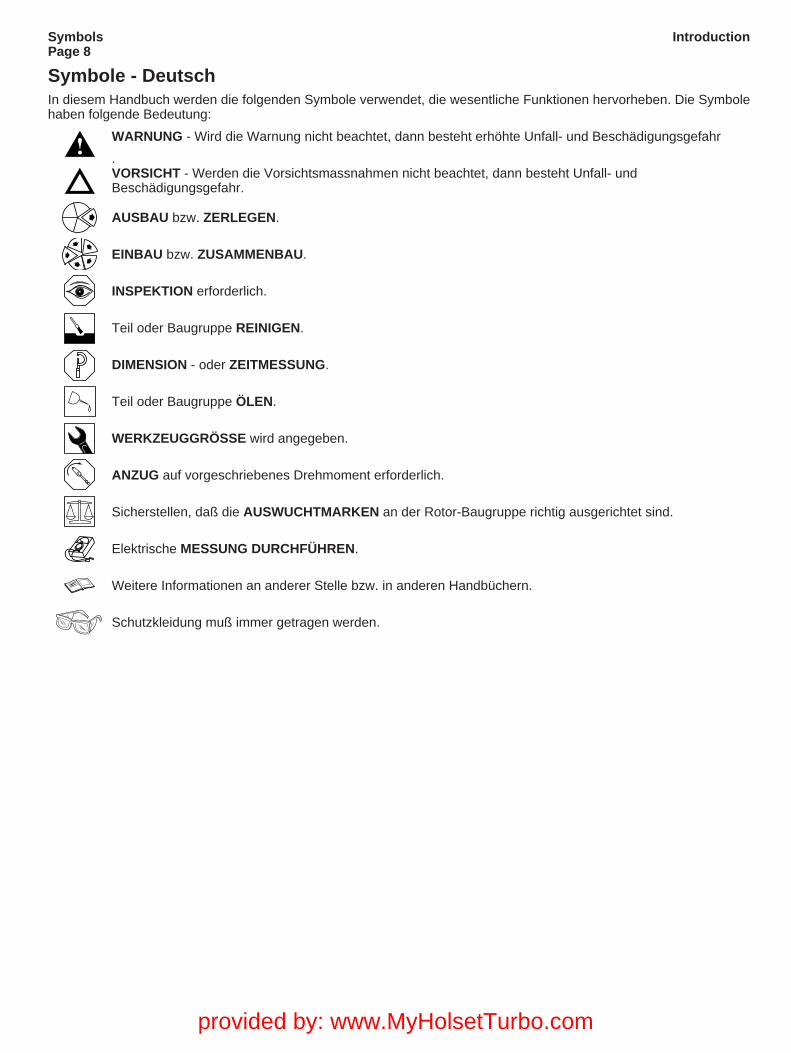
Symbole - DeutschIn diesem Handbuch werden die folgenden Symbole verwendet, die wesentliche Funktionen hervorheben. Die Symbolehaben folgende Bedeutung:
WARNUNG - Wird die Warnung nicht beachtet, dann besteht erhöhte Unfall- und Beschädigungsgefahr
.VORSICHT - Werden die Vorsichtsmassnahmen nicht beachtet, dann besteht Unfall- undBeschädigungsgefahr.
AUSBAU bzw. ZERLEGEN.
EINBAU bzw. ZUSAMMENBAU.
INSPEKTION erforderlich.
Teil oder Baugruppe REINIGEN.
DIMENSION - oder ZEITMESSUNG.
Teil oder Baugruppe ÖLEN.
WERKZEUGGRÖSSE wird angegeben.
ANZUG auf vorgeschriebenes Drehmoment erforderlich.
Sicherstellen, daß die AUSWUCHTMARKEN an der Rotor-Baugruppe richtig ausgerichtet sind.
Elektrische MESSUNG DURCHFÜHREN.
Weitere Informationen an anderer Stelle bzw. in anderen Handbüchern.
Schutzkleidung muß immer getragen werden.
provided by: www.MyHolsetTurbo.com
SymbolsPage 9
Introduction
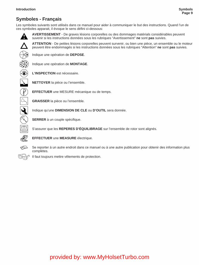
Symboles - FrançaisLes symboles suivants sont utilisés dans ce manuel pour aider à communiquer le but des instructions. Quand l’un deces symboles apparait, il évoque le sens défini ci-dessous:
AVERTISSEMENT - De graves lésions corporelles ou des dommages matérials considérables peuventsuvenir si les instructions données sous les rubriques “Avertissement” ne sont pas suivies.
ATTENTION - De petites lésions corporelles peuvent survenir, ou bien une pièce, un ensemble ou le moteurpeuvent être endommagés si les instructions données sous les rubriques “Attention” ne sont pas suivies.
Indique une opération de DEPOSE.
Indique une opération de MONTAGE.
L’INSPECTION est nécessaire.
NETTOYER la pièce ou l’ensemble.
EFFECTUER une MESURE mécanique ou de temps.
GRAISSER la pièce ou l’ensemble.
Indique qu’une DIMENSION DE CLE ou D’OUTIL sera donnée.
SERRER à un couple spécifique.
S’assurer que les REPERES D’ÉQUILIBRAGE sur l’ensemble de rotor sont alignés.
EFFECTUER une MEASURE électrique.
Se reporter à un autre endroit dans ce manuel ou à une autre publication pour obtenir des information pluscomplètes.
Il faut toujours mettre vêtements de protection.
provided by: www.MyHolsetTurbo.com
SymbolsPage 10
Introduction
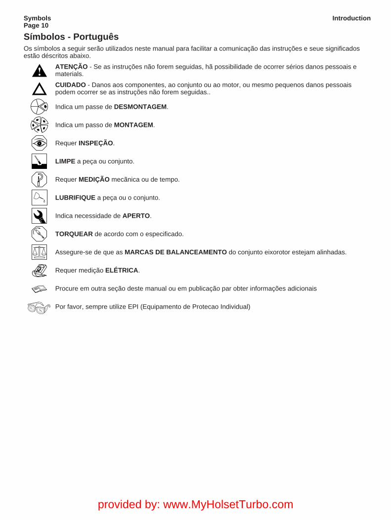
Símbolos - PortuguêsOs símbolos a seguir serão utilizados neste manual para facilitar a comunicação das instruções e seue significadosestão déscritos abaixo.
ATENÇÃO - Se as instruções não forem seguidas, hã possibilidade de ocorrer sérios danos pessoais ematerials.
CUIDADO - Danos aos componentes, ao conjunto ou ao motor, ou mesmo pequenos danos pessoaispodem ocorrer se as instruções não forem seguidas..
Indica um passe de DESMONTAGEM.
Indica um passo de MONTAGEM.
Requer INSPEÇÃO.
LIMPE a peça ou conjunto.
Requer MEDIÇÃO mecãnica ou de tempo.
LUBRIFIQUE a peça ou o conjunto.
Indica necessidade de APERTO.
TORQUEAR de acordo com o especificado.
Assegure-se de que as MARCAS DE BALANCEAMENTO do conjunto eixorotor estejam alinhadas.
Requer medição ELÉTRICA.
Procure em outra seção deste manual ou em publicação par obter informações adicionais
Por favor, sempre utilize EPI (Equipamento de Protecao Individual)
provided by: www.MyHolsetTurbo.com
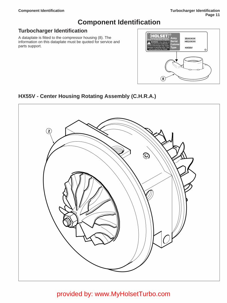
Component IdentificationTurbocharger IdentificationA dataplate is fitted to the compressor housing (8). Theinformation on this dataplate must be quoted for service andparts support.
Turbocharger IdentificationPage 11
Component Identification
8
35XXXXXH01XXXX
HX55V
HX55V - Center Housing Rotating Assembly (C.H.R.A.)
2
provided by: www.MyHolsetTurbo.com

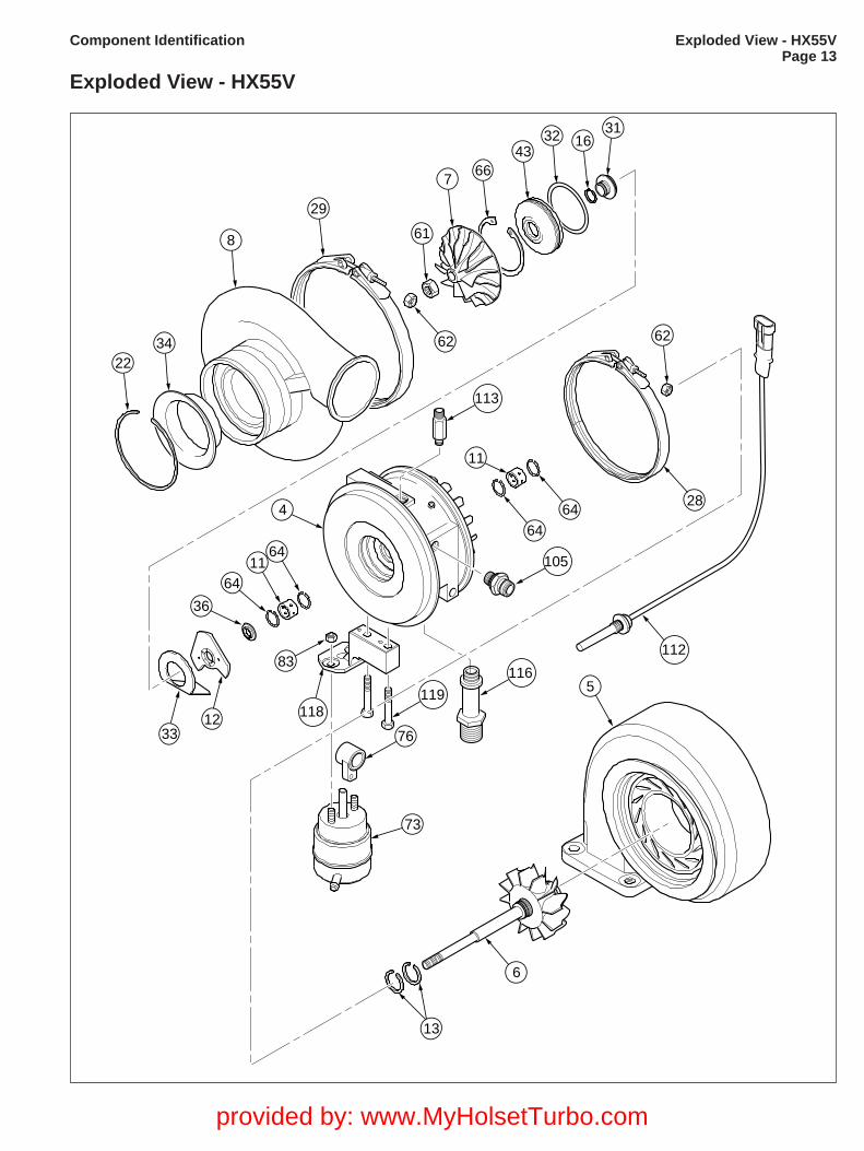
Components - HX55VItem No. Description Quantity
4 Bearing Housing 1
5 Turbine Housing 1
6 Assembly Turbine Wheel 1
7 Compressor Wheel 1
8 Compressor Housing 1
11 Journal Bearing 2
12 Thrust Bearing 1
13 Piston Ring Seal, Turbine 2
16 Piston Ring Seal, Compressor 1
22 Inlet Baffle Retaining Ring 1
28 V-band Clamp Turbine 1
29 V-band Clamp Compressor 1
31 Oil Slinger 1
32 O-Ring Seal, Compressor 1
33 Oil Baffle 1
34 Inlet Baffle 1
36 Thrust Collar 1
43 Oil Seal Plate 1
61 Locknut Compressor Wheel 1
62 V-band Locknut 2
64 Ring Retaining Bearing (Snap Ring) 4
66 Insert, Retaining Ring 1
73 Actuator Can 1
76 Link End Adjuster 1
83 Locknut Actuator 2
105 Connecter Male 1
112 Speed Probe 1
113 Adaptor Oil Inlet 1
114 'O' Ring Seal Oil Inlet 1
115 'O' Ring Seal Male Connector 1
116 Adaptor Oil Outlet 1
117 'O' Ring Seal , Oil Outlet 1
118 Actuator Bracket 1
119 Bracket Bolts 2
120 Cap Head Screw 1
Components - HX55VPage 12
Component Identification
provided by: www.MyHolsetTurbo.com
2234
6411
5
8
62
29
61
62
6
13
112
1233
4
36
64
6464
105
116
76
73
119
113
118
83
11
766
4332 16
31
28
Exploded View - HX55VPage 13
Component Identification
Exploded View - HX55V
provided by: www.MyHolsetTurbo.com

Oil Control ValveThe valve controls the pressure applied to the actuator inresponse to signals sent by the engines electronic controlunitThere are no service able parts inside.If the engine diagnostics indicate a problem with the valve itmust be relaced. Contact your approved Dealer for partsand avialablilty
Oil Control ValvePage 14
provided by: www.MyHolsetTurbo.com
12
3
4 5 6
7
89
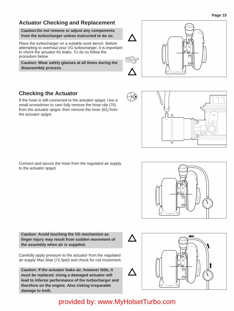
Actuator Checking and ReplacementCaution:Do not remove or adjust any componentsfrom the turbocharger unless instructed to do so.
Place the turbocharger on a suitable work bench. Beforeattempting to overhaul your VG turbocharger, it is importantto check the actuator for leaks. To do so follow theprocedure below.
Caution: Wear safety glasses at all times during thedisassembly process.
Checking the ActuatorIf the hose is still connected to the actuator spigot, Use asmall screwdriver to care fully remove the hose clip (75)from the actuator spigot. then remove the hose (81) fromthe actuator spigot.
Connect and secure the hose from the regulated air supplyto the actuator spigot.
12
3
4 5 6
7
89
Page 15
Caution: Avoid touching the VG mechanism asfinger injury may result from sudden movement ofthe assembly when air is supplied.
Carefully apply pressure to the actuator from the regulatedair supply Max 5bar (72.5psi) and check for rod movement.
Caution: If the actuator leaks air, however little, itmust be replaced. Using a damaged actuator willlead to inferior performance of the turbocharger andtherefore on the engine. Also risking irreparabledamage to both.
provided by: www.MyHolsetTurbo.com
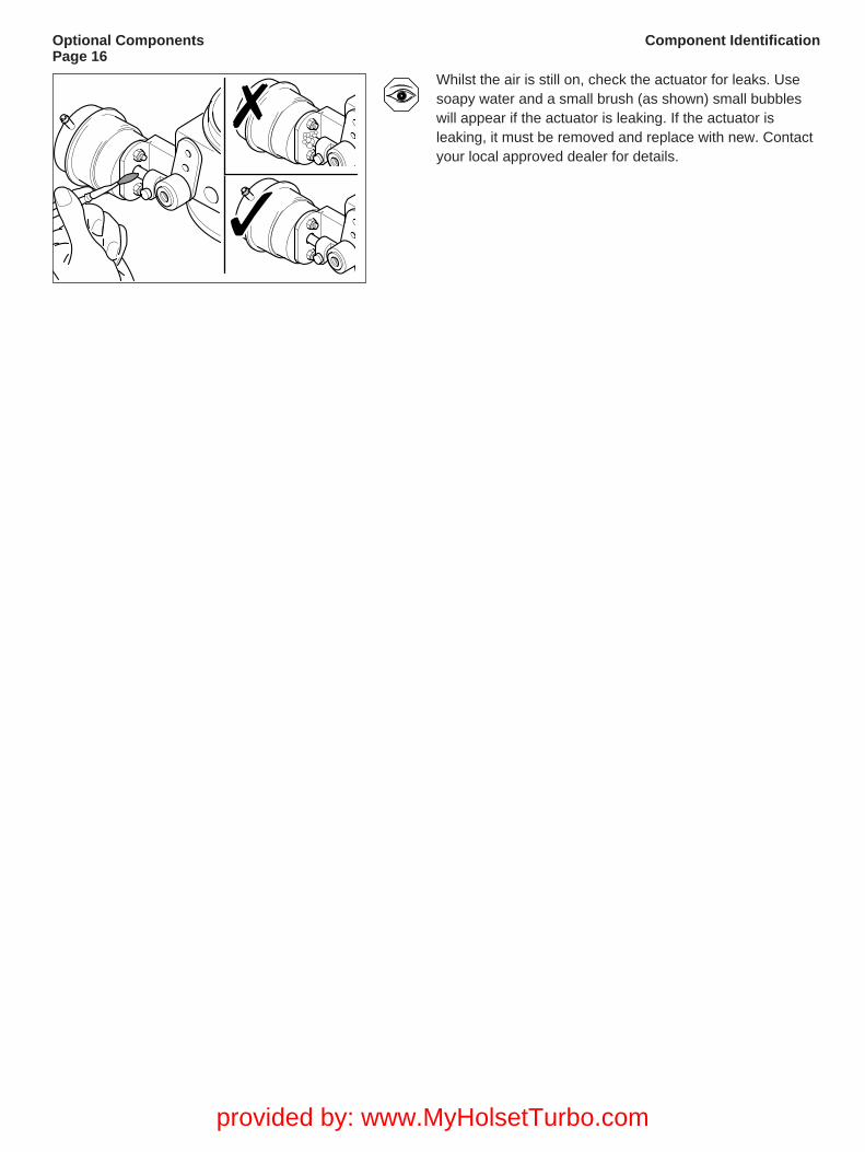
Whilst the air is still on, check the actuator for leaks. Usesoapy water and a small brush (as shown) small bubbleswill appear if the actuator is leaking. If the actuator isleaking, it must be removed and replace with new. Contactyour local approved dealer for details.
Optional ComponentsPage 16
Component Identification
provided by: www.MyHolsetTurbo.com
Page 17Service Tools
Page 17Actuator Replacement
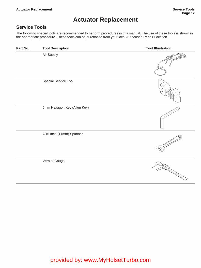
Actuator ReplacementService ToolsThe following special tools are recommended to perform procedures in this manual. The use of these tools is shown inthe appropriate procedure. These tools can be purchased from your local Authorised Repair Location.
Part No. Tool Description Tool Illustration
Air Supply
Special Service Tool
5mm Hexagon Key (Allen Key)
7/16 Inch (11mm) Spanner
Vernier Gauge
provided by: www.MyHolsetTurbo.com

Page 18
Before attempting to overhaul your turbocharger, it isreccomended that you remove the actuator (74) and linkend adjuster (76). to do so, follow the process below.Identify the required setting dimension (this will be stampedon the bearing housing in the position shown) Write thedimension down and keep it in a safe place. This settingwill typically be between 58 and 59mm, however anydecimal places must be noted.
Apply air pressure.
Using allen key, slacken off cap head screw (120 ) andremove end adjuster (76 ).
Remove 2 x actuator locknuts (83)Remove actuator from bracket.
Page 18Actuator Replacement
12
3
4 5 6
7
89
provided by: www.MyHolsetTurbo.com
Page 19Service Tools
Page 19Actuator Replacement
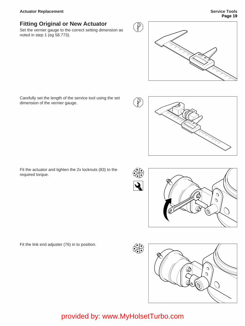
Fitting Original or New ActuatorSet the vernier gauge to the correct setting dimension asnoted in step 1 (eg 58.773).
Carefully set the length of the service tool using the setdimension of the vernier gauge.
Fit the actuator and tighten the 2x locknuts (83) to therequired torque.
Fit the link end adjuster (76) in to position.
provided by: www.MyHolsetTurbo.com
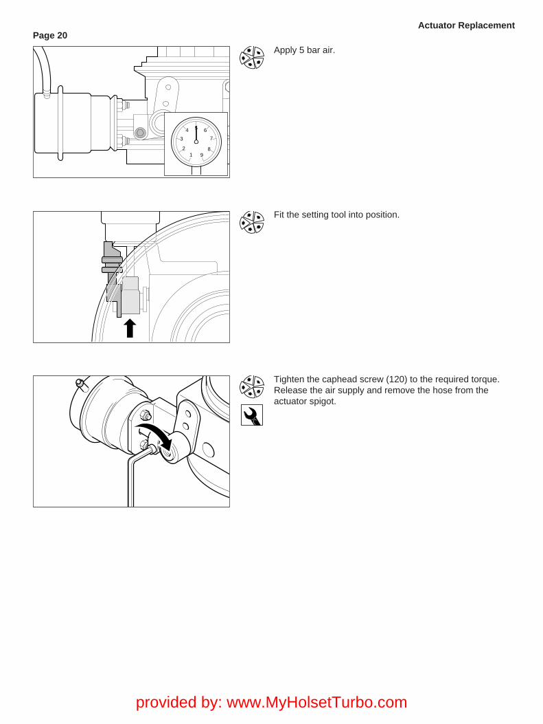
Apply 5 bar air.
Fit the setting tool into position.
Tighten the caphead screw (120) to the required torque.Release the air supply and remove the hose from theactuator spigot.
Page 20Actuator Replacement
12
3
4 5 6
7
89
provided by: www.MyHolsetTurbo.com

Page 21
provided by: www.MyHolsetTurbo.com
Page 22Speed Probe Replacement
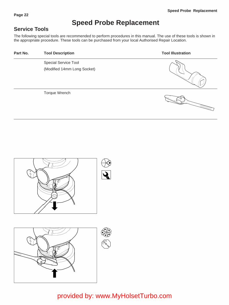
Speed Probe ReplacementService ToolsThe following special tools are recommended to perform procedures in this manual. The use of these tools is shown inthe appropriate procedure. These tools can be purchased from your local Authorised Repair Location.
Part No. Tool Description Tool Illustration
Special Service Tool
(Modified 14mm Long Socket)
Torque Wrench
provided by: www.MyHolsetTurbo.com
Page 23Service Tools
Page 23Component Disassembly and Assembly
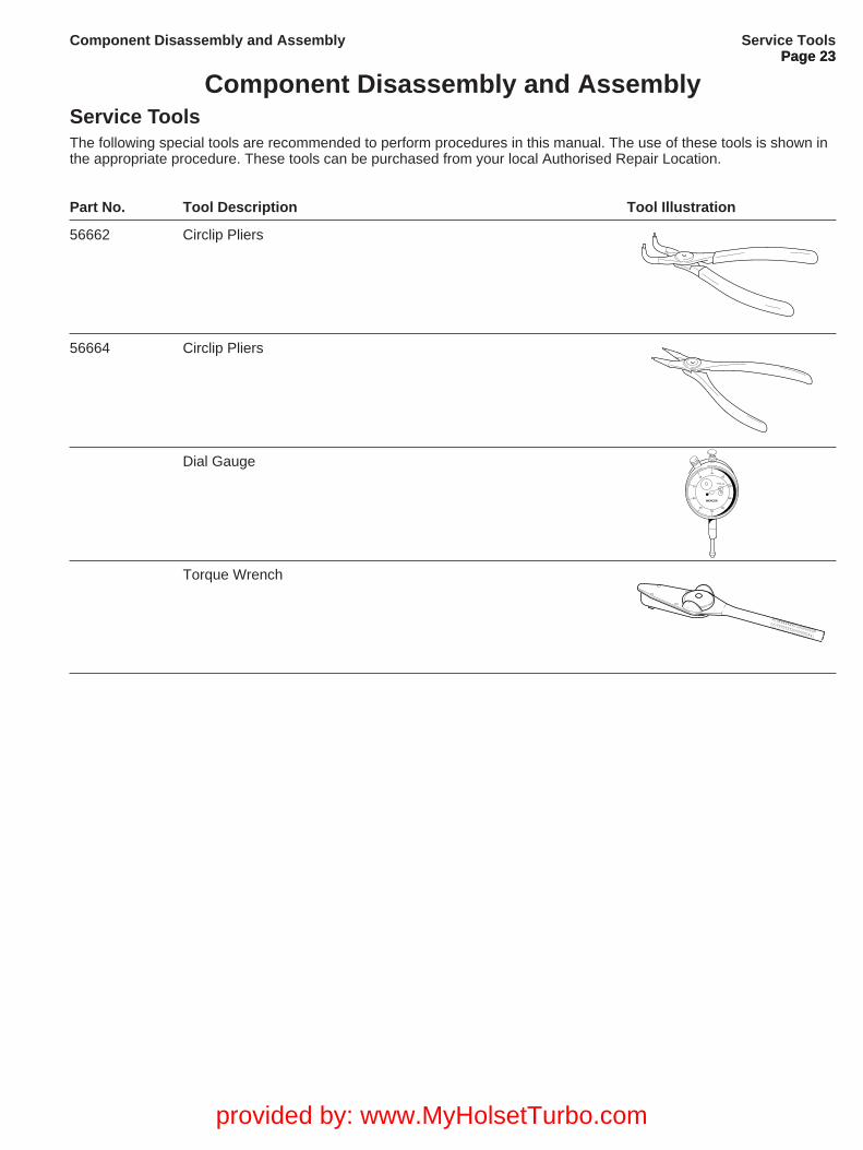
Component Disassembly and AssemblyService ToolsThe following special tools are recommended to perform procedures in this manual. The use of these tools is shown inthe appropriate procedure. These tools can be purchased from your local Authorised Repair Location.
Part No. Tool Description Tool Illustration
56662 Circlip Pliers
56664 Circlip Pliers
Dial Gauge-0+
1010
2020
3030
404050
MERCER
TYPE 20
Torque Wrench
provided by: www.MyHolsetTurbo.com
Page 24
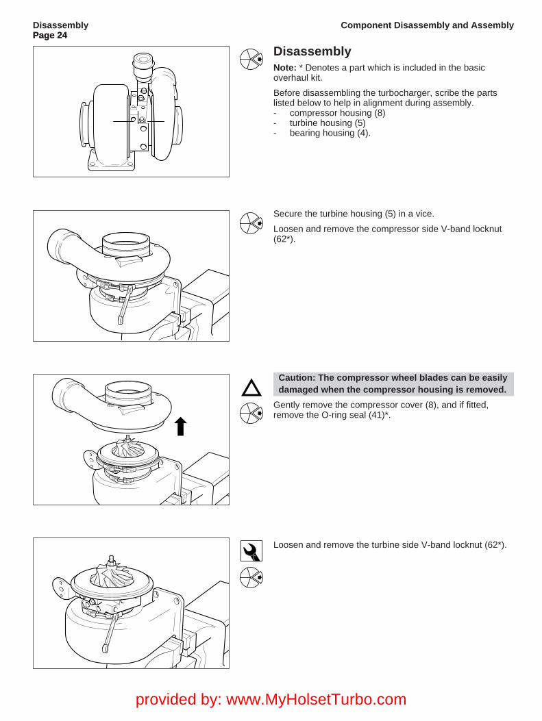
DisassemblyNote: * Denotes a part which is included in the basicoverhaul kit.
Before disassembling the turbocharger, scribe the partslisted below to help in alignment during assembly.- compressor housing (8)- turbine housing (5)- bearing housing (4).
Secure the turbine housing (5) in a vice.
Loosen and remove the compressor side V-band locknut(62*).
Caution: The compressor wheel blades can be easilydamaged when the compressor housing is removed.
Gently remove the compressor cover (8), and if fitted,remove the O-ring seal (41)*.
Loosen and remove the turbine side V-band locknut (62*).
DisassemblyPage 24
Component Disassembly and Assembly
provided by: www.MyHolsetTurbo.com
Page 25
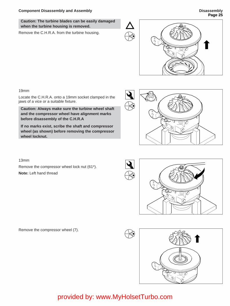
Caution: The turbine blades can be easily damagedwhen the turbine housing is removed.
Remove the C.H.R.A. from the turbine housing.
19mm
Locate the C.H.R.A. onto a 19mm socket clamped in thejaws of a vice or a suitable fixture.
Caution: Always make sure the turbine wheel shaftand the compressor wheel have alignment marksbefore disassembly of the C.H.R.A
If no marks exist, scribe the shaft and compressorwheel (as shown) before removing the compressorwheel locknut.
13mm
Remove the compressor wheel lock nut (61*).
Note: Left hand thread
Remove the compressor wheel (7).
DisassemblyPage 25
Component Disassembly and Assembly
provided by: www.MyHolsetTurbo.com
Page 26
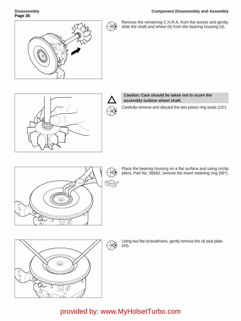
Remove the remaining C.H.R.A. from the socket and gentlyslide the shaft and wheel (6) from the bearing housing (4).
Caution: Care should be taken not to score theassembly turbine wheel shaft.
Carefully remove and discard the two piston ring seals (13*).
Using two flat screwdrivers, gently remove the oil seal plate(43).
DisassemblyPage 26
Component Disassembly and Assembly
Place the bearing housing on a flat surface and using circlippliers, Part No. 56662, remove the insert retaining ring (66*).
provided by: www.MyHolsetTurbo.com
Page 27
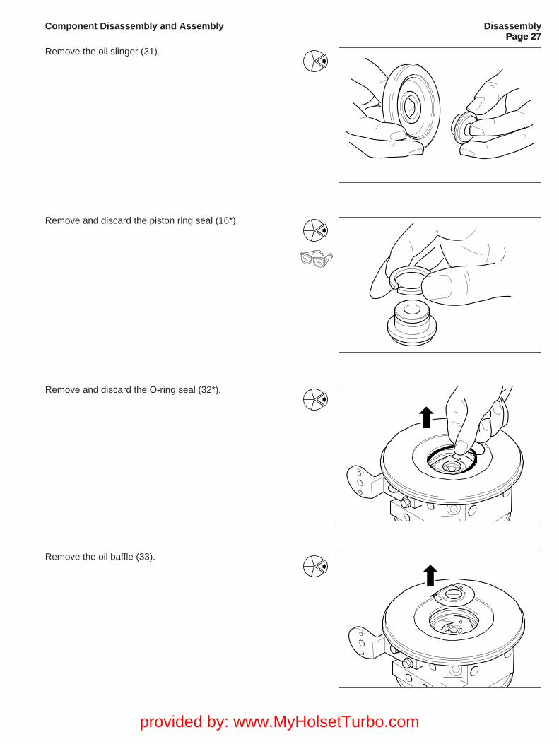
Remove the oil slinger (31).
Remove and discard the piston ring seal (16*).
Remove and discard the O-ring seal (32*).
DisassemblyPage 27
Component Disassembly and Assembly
Remove the oil baffle (33).
provided by: www.MyHolsetTurbo.com
Page 28
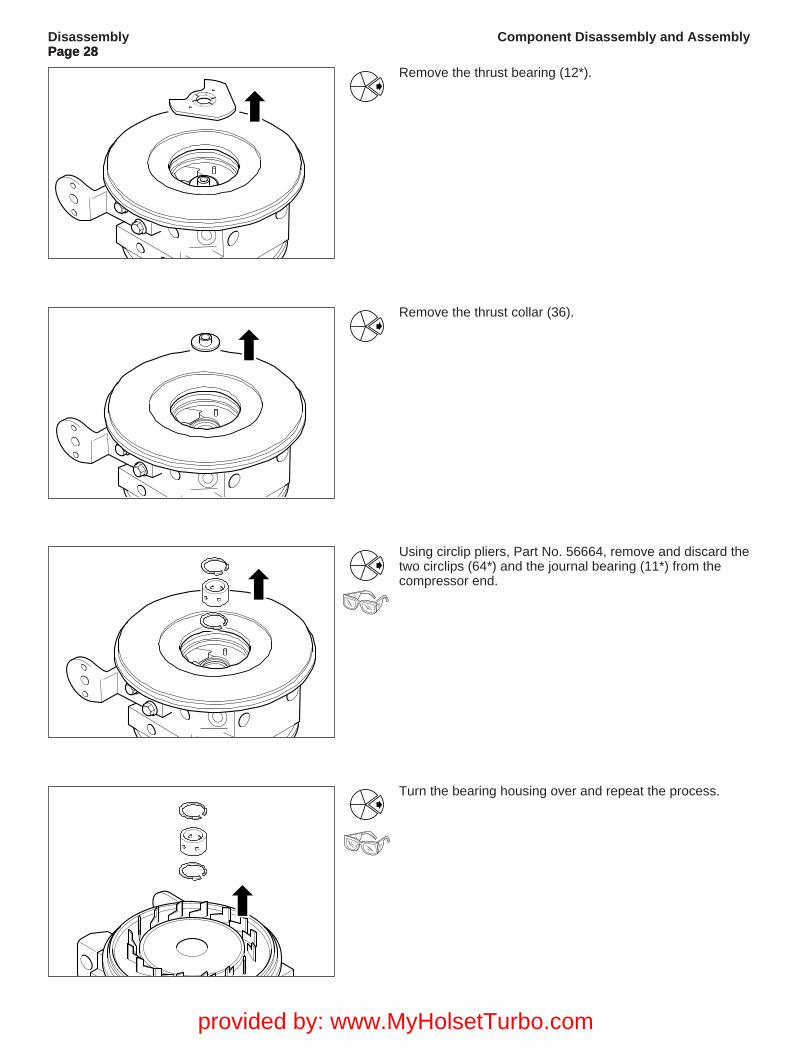
Remove the thrust collar (36).
Using circlip pliers, Part No. 56664, remove and discard thetwo circlips (64*) and the journal bearing (11*) from thecompressor end.
Turn the bearing housing over and repeat the process.
DisassemblyPage 28
Component Disassembly and Assembly
Remove the thrust bearing (12*).
provided by: www.MyHolsetTurbo.com
Page 29
(b)
(c)
(d)
(d)
CleaningPage 29
Component Disassembly and Assembly
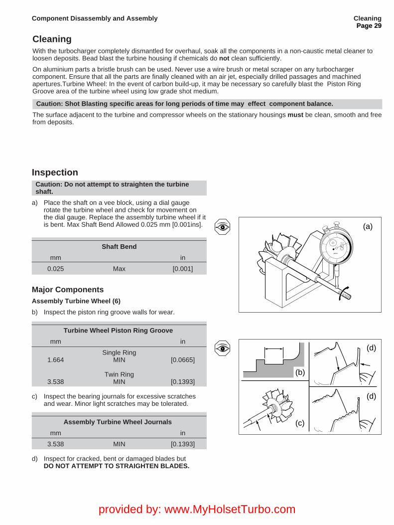
InspectionCaution: Do not attempt to straighten the turbineshaft.
a) Place the shaft on a vee block, using a dial gaugerotate the turbine wheel and check for movement onthe dial gauge. Replace the assembly turbine wheel if itis bent. Max Shaft Bend Allowed 0.025 mm [0.001ins].
Shaft Bend
mm in
0.025 Max [0.001]
Major ComponentsAssembly Turbine Wheel (6)
b) Inspect the piston ring groove walls for wear.
Turbine Wheel Piston Ring Groove
mm in
Single Ring1.664 MIN [0.0665]
Twin Ring3.538 MIN [0.1393]
c) Inspect the bearing journals for excessive scratches and wear. Minor light scratches may be tolerated.
Assembly Turbine Wheel Journals
mm in
3.538 MIN [0.1393]
d) Inspect for cracked, bent or damaged blades but DO NOT ATTEMPT TO STRAIGHTEN BLADES.
CleaningWith the turbocharger completely dismantled for overhaul, soak all the components in a non-caustic metal cleaner toloosen deposits. Bead blast the turbine housing if chemicals do not clean sufficiently.
On aluminium parts a bristle brush can be used. Never use a wire brush or metal scraper on any turbochargercomponent. Ensure that all the parts are finally cleaned with an air jet, especially drilled passages and machinedapertures.Turbine Wheel: In the event of carbon build-up, it may be necessary so carefully blast the Piston RingGroove area of the turbine wheel using low grade shot medium.
Caution: Shot Blasting specific areas for long periods of time may effect component balance.
The surface adjacent to the turbine and compressor wheels on the stationary housings must be clean, smooth and freefrom deposits.
(a)-0+
1010
2020
3030
4040
50
MERCER
TYPE 20
provided by: www.MyHolsetTurbo.com
Page 30
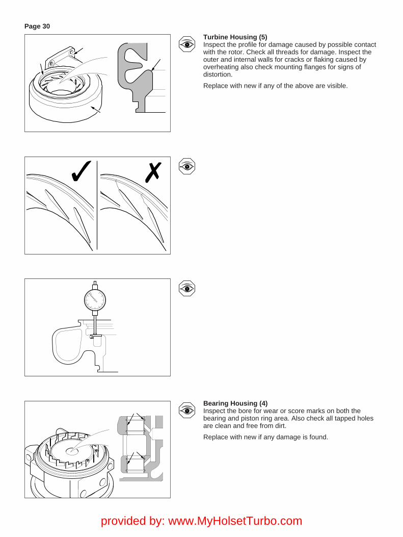
Turbine Housing (5)Inspect the profile for damage caused by possible contactwith the rotor. Check all threads for damage. Inspect theouter and internal walls for cracks or flaking caused byoverheating also check mounting flanges for signs ofdistortion.
Replace with new if any of the above are visible.
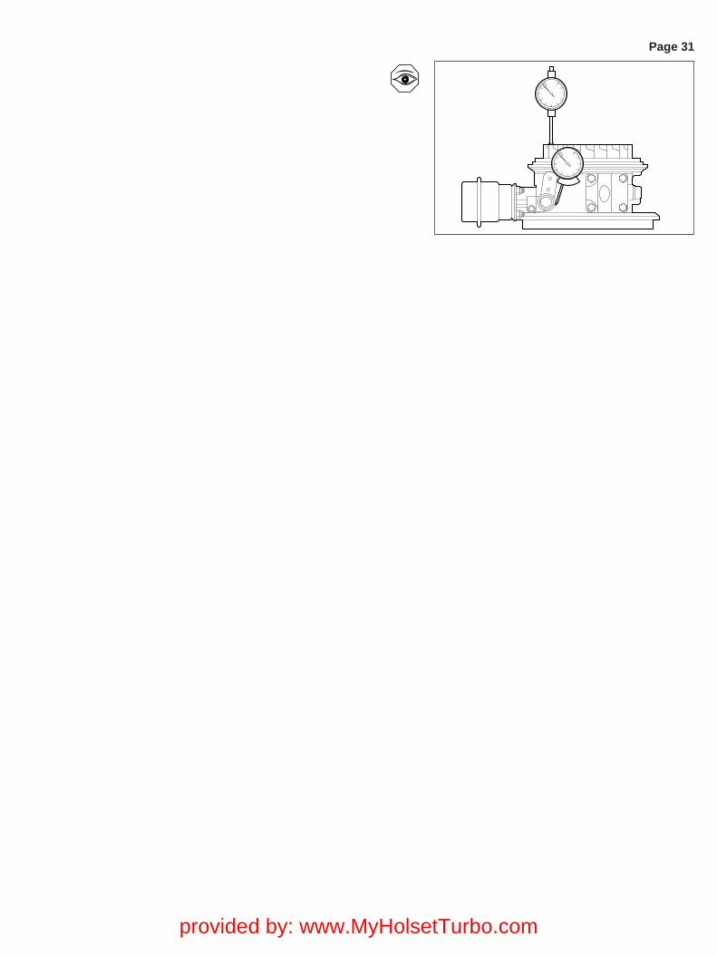
Bearing Housing (4)Inspect the bore for wear or score marks on both thebearing and piston ring area. Also check all tapped holesare clean and free from dirt.
Replace with new if any damage is found.
provided by: www.MyHolsetTurbo.com
Page 31
provided by: www.MyHolsetTurbo.com
Page 32
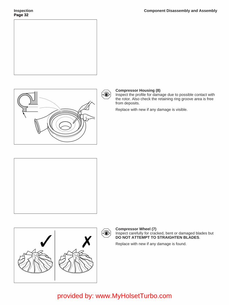
Compressor Housing (8)Inspect the profile for damage due to possible contact withthe rotor. Also check the retaining ring groove area is freefrom deposits.
Replace with new if any damage is visible.
InspectionPage 32
Component Disassembly and Assembly
Compressor Wheel (7)Inspect carefully for cracked, bent or damaged blades butDO NOT ATTEMPT TO STRAIGHTEN BLADES.
Replace with new if any damage is found.
provided by: www.MyHolsetTurbo.com
Page 33
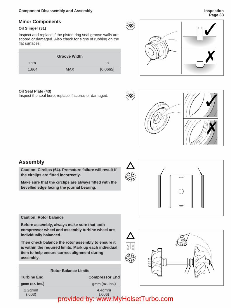
Minor ComponentsOil Slinger (31)
Inspect and replace if the piston ring seal groove walls arescored or damaged. Also check for signs of rubbing on theflat surfaces.
Groove Width
mm in
1.664 MAX [0.0665]
Oil Seal Plate (43)Inspect the seal bore, replace if scored or damaged.
AssemblyCaution: Circlips (64). Premature failure will result ifthe circlips are fitted incorrectly.
Make sure that the circlips are always fitted with thebevelled edge facing the journal bearing.
InspectionPage 33
Component Disassembly and Assembly
Caution: Rotor balance
Before assembly, always make sure that bothcompressor wheel and assembly turbine wheel areindividually balanced.
Then check balance the rotor assembly to ensure itis within the required limits. Mark up each individualitem to help ensure correct alignment duringassembly.
Rotor Balance Limits
Turbine End Compressor End
gmm (oz. ins.) gmm (oz. ins.)
2.2gmm 4.4gmm(.003) (.006)
provided by: www.MyHolsetTurbo.com
Page 34
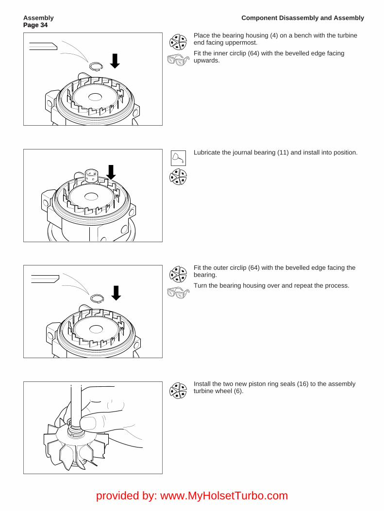
Lubricate the journal bearing (11) and install into position.
Fit the outer circlip (64) with the bevelled edge facing thebearing.
Turn the bearing housing over and repeat the process.
Install the two new piston ring seals (16) to the assemblyturbine wheel (6).
AssemblyPage 34
Component Disassembly and Assembly
Place the bearing housing (4) on a bench with the turbineend facing uppermost.
Fit the inner circlip (64) with the bevelled edge facingupwards.
provided by: www.MyHolsetTurbo.com
Page 35
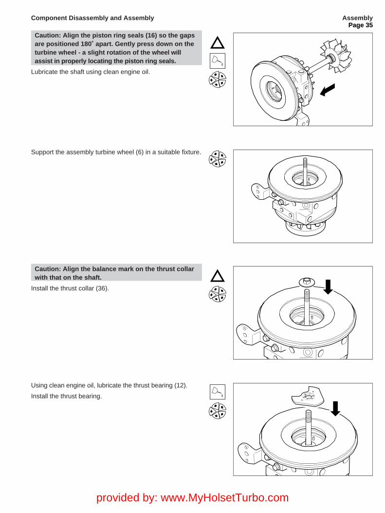
Support the assembly turbine wheel (6) in a suitable fixture.
Using clean engine oil, lubricate the thrust bearing (12).
Install the thrust bearing.
AssemblyPage 35
Component Disassembly and Assembly
Caution: Align the piston ring seals (16) so the gapsare positioned 180˚ apart. Gently press down on theturbine wheel - a slight rotation of the wheel willassist in properly locating the piston ring seals.
Lubricate the shaft using clean engine oil.
Caution: Align the balance mark on the thrust collarwith that on the shaft.
Install the thrust collar (36).
provided by: www.MyHolsetTurbo.com
Page 36
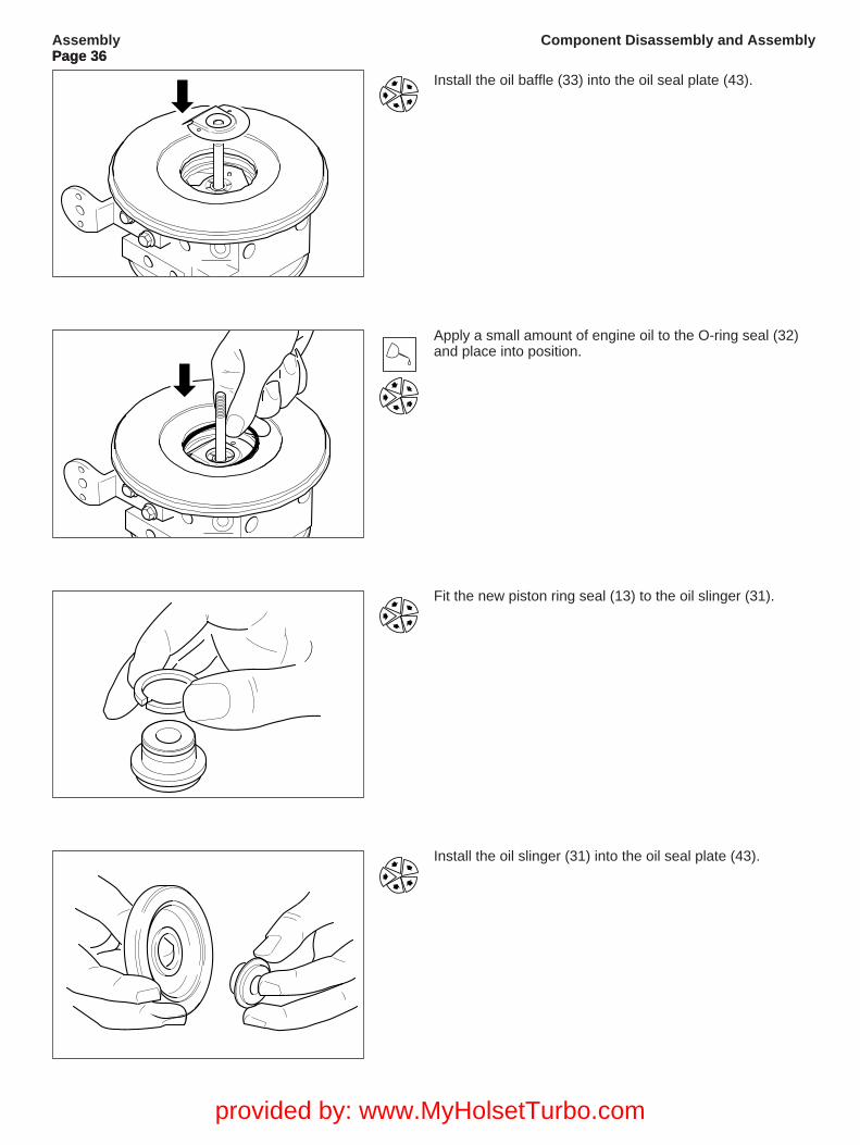
Fit the new piston ring seal (13) to the oil slinger (31).
Apply a small amount of engine oil to the O-ring seal (32)and place into position.
Install the oil slinger (31) into the oil seal plate (43).
AssemblyPage 36
Component Disassembly and Assembly
Install the oil baffle (33) into the oil seal plate (43).
provided by: www.MyHolsetTurbo.com
Page 37
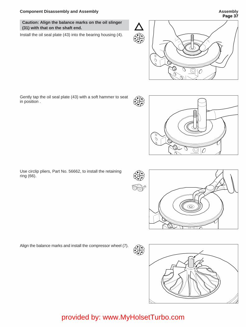
Gently tap the oil seal plate (43) with a soft hammer to seatin position .
Use circlip pliers, Part No. 56662, to install the retainingring (66).
Align the balance marks and install the compressor wheel (7).
AssemblyPage 37
Component Disassembly and Assembly
Caution: Align the balance marks on the oil slinger(31) with that on the shaft end.
Install the oil seal plate (43) into the bearing housing (4).
provided by: www.MyHolsetTurbo.com
Page 38
-0+1010
2020
3030
404050
MERCER
TYPE 20
-0+10
10
2020
3030
4040
50
ME
RC
ER T
YP
E 20
AssemblyPage 38
Component Disassembly and Assembly
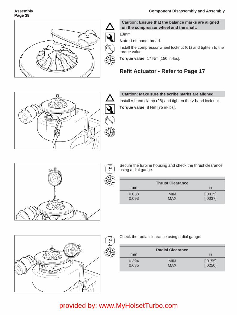
Caution: Ensure that the balance marks are alignedon the compressor wheel and the shaft.
13mm
Note: Left hand thread.
Install the compressor wheel locknut (61) and tighten to thetorque value.
Torque value: 17 Nm [150 in-lbs].
Refit Actuator - Refer to Page 17
Caution: Make sure the scribe marks are aligned.
Install v-band clamp (28) and tighten the v-band lock nut
Torque value: 8 Nm [75 in-lbs].
Secure the turbine housing and check the thrust clearanceusing a dial gauge.
Thrust Clearancemm in
0.038 MIN [.0015]0.093 MAX [.0037]
Check the radial clearance using a dial gauge.
Radial Clearancemm in
0.394 MIN [.0155]0.635 MAX [.0250]
provided by: www.MyHolsetTurbo.com
Page 39Assembly
Page 39Component Disassembly and Assembly
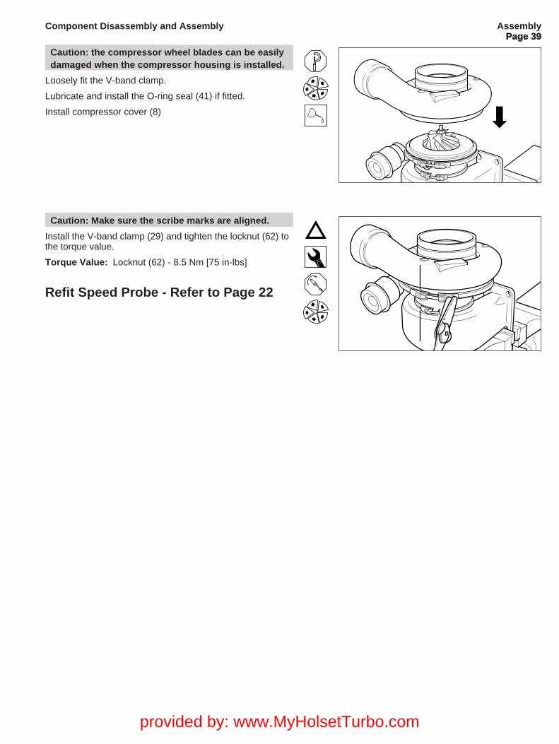
Caution: the compressor wheel blades can be easilydamaged when the compressor housing is installed.
Loosely fit the V-band clamp.
Lubricate and install the O-ring seal (41) if fitted.
Install compressor cover (8)
Caution: Make sure the scribe marks are aligned.
Install the V-band clamp (29) and tighten the locknut (62) tothe torque value.
Torque Value: Locknut (62) - 8.5 Nm [75 in-lbs]
Refit Speed Probe - Refer to Page 22
provided by: www.MyHolsetTurbo.com
Page 40
Installation Data1. Mount the turbocharger on the turbine inlet flange. All other connections must be flexible and heavy pipework
should be supported. Always pre-lube with clean engine oil.
2. Always position the bearing housing so that the oil drain is at the bottom and kept within 22˚ of the vertical centre line when installed on the engine.
3. Oil should be filtered below 15/20 microns. The oil quality must be as specified by the engine manufacturer. e.g. API - CD (MIL - L - 2104C). Improvement in life can be obtained by using super high performance diesel (SPHD) oils, particularly where extended oil drain periods are used.
4. Oil pressure must show at the turbocharger oil inlet within 3 - 4 seconds of engine firing to prevent damage to turbocharger bearing system from lack of lubrication.
5. The minimum oil pressure, when the engine is on load must be 210 kPa [2.0 kgf/cm2, 30 lbf/in2] and pressures up to 415 kPa [4.0 kgf/cm2, 60 lb/in2] are satisfactory. Under idling conditions the pressure should not fall below 70 kPa[0.7 kgf/cm2. 10lbf/in2].
6. The oil inlet pipe should be 9.5 mm [0.375 in.] bore minimum and the oil drain pipe should be no smaller than the turbocharger oil drain flange minimum. The oil must drain downwards by gravity from the turbocharger into the
engine under all operating conditions.
7. Air cleaner pressure drop should not exceed 500 mm [20 in.] of water. Avoid damp/wet air conditions in filter as thiscan dramatically increase pressure drop on a temporary basis.
8. The exhaust back pressure after the turbocharger should not exceed 500 mm [20 in.] of water. Consult Holset where high restrictions are expected, particularly when exhaust brakes are to be used.
Installation DataPage 40
Component Disassembly and Assembly
provided by: www.MyHolsetTurbo.com

Page 41
Installation Checklist1. Always understand why the original turbocharger needs replacing before fitting another unit.
2. Check the turbocharger dataplate to ensure the Part No. is correct for the engine/application.
3. Check the engine intake and exhaust systems are clean and without obstruction ie. free from oil, gasket pieces, dust/dirt/carbon or foreign objects.
4. Replace the oil and air filters using those only recommended by the equipment manufacturer.
5. Change the engine oil using the type specified by the engine manufacturer. A minimum of CD oil is needed for the turbocharger diesel engine.
6. Check that the turbocharger oil inlet and drain connections are clean and free from obstruction and will not leak under pressure.
7. Mount the turbocharger on the exhaust flange and check that the turbine inlet gasket fits properly without obstructing the gas passages.
8. Rotate the turbocharger central bearing housing (4) so that the oil inlet and drain are in the vertical position. Up to 22 Degrees from vertical is permitted.
9. Pour some clean engine oil into the turbocharger oil inlet hole and twist the turbocharger rotor assembly until clean oil starts to flow out of the oil drain flange.
10. Rotate the compressor housing (8) into the correct position and assemble the air intake and boost outlet connections. Check that the connections are well made and do not have a possibility of leaking under pressure.
11. Assemble the exhaust system to the turbine housing outlet (5). Check that the gasket/connection is well made and will not leak in use.
12. Check the exhaust system is well supported and not causing excess loads on the turbocharger. Fit any supports/brackets back in position.
13. Check all hose/pipe clamps/studs/nuts are correctly torqued.
14. Carefully assemble the turbocharger oil inlet pipe and check that the connection is clean, well made and will not leak under pressure.Do NOT use liquid gasket substances as any excess will enter the turbocharger oil system and obstruct oil flow damaging the turbocharger bearing system in use.
15. Crank the engine WITHOUT firing (engine/fuel pump stop out) until engine oil flows out of the turbocharger drain flange.
16. Assemble the oil drain pipe and check that the connection is well made without obstruction.
17. Check that the engine fuel injection system is correctly regulated as per the manufacturers specifications.
18. Start the engine and leave ticking over at idle for approx. 1 minute so that the oil supply system is fully operational including the new filter(s).
19. Accelerate the engine and check that there are no leaks/obstructions of the air/oil/gas under pressure.
20. Check that the hoses/connections do not deform under normal operation.
21. Before switching off the engine, leave it ticking over at idle for at least 1 minute to cool the turbine.
Installation ChecklistPage 41
Component Disassembly and Assembly