Embed Size (px)
Citation preview
H o l o n i c a p p ro a ch fo r c o n t ro l a n d
coordination of distributed sensors
A. Benaskeur
H. Irandoust
DRDC Valcartier
Defence R&D Canada – ValcartierTechnical Report
DRDC Valcartier TR 2008-015
August 2008

Holonic approach for control and coordination of
distributed sensors
A. Benaskeur
H. Irandoust
Defence R&D Canada – Valcartier
Defence R&D Canada – Valcartier
Technical Report
DRDC Valcartier TR 2008-015
August 2008

Principal Author
A. Benaskeur
Approved by
Eloi BosseHead/Section
Approved for release by
C. CarrierChief Scientist
c© Her Majesty the Queen in Right of Canada as represented by the Minister of NationalDefence, 2008
c© Sa Majeste la Reine (en droit du Canada), telle que representee par le ministre de laDefense nationale, 2008
Abstract
Some of the high-level issues in military sensor management (SM), and in Command and
Control (C2) systems in general, are related to their organizational forms and distributed ar-
chitectures. In order to meet safety and timeliness criteria of decision making, cooperation,
coordination, and communication among multiple decision nodes are required. Moreover,
an effective decomposition of the decision process is critical. The objective of this report
is to present control architectures and control methods that are applicable to the manage-
ment of sensors for tactical surveillance. It is explained that the hierarchical and recursive
structure of holonic architecture provides the required flexibility and robustness without
deviating significantly from the current military command structure. The application of
the holonic control methodology to tactical SM is presented.
Resume
Quelques uns des problemes de haut niveau de gestion des capteurs dans le cadre militaire
et du Commandement et Controle (C2) en general, sont lies aux formes organisationnelles et
aux architectures distribuees qui les caracterisent. Afin de satisfaire les criteres de securite
et de rapidite de la prise de decision, la cooperation, la coordination et la communication,
parmi les multiples noeuds de decision, sont requises. De plus, une decomposition efficace
du processus decisionnel est des plus critiques. L’objectif de ce rapport est de presenter les
architectures et les methodes de controle applicables a la gestion des capteurs pour la sur-
veillance tactique. On a demontre que la structure hierarchique et recursive de l’architecture
holonique offrait la flexibilite et la robustesse requises sans devier de maniere significative
de la structure de commandement militaire actuelle. L’application de la methodologie du
controle holonique a la gestion des ressources tactiques est presentee.
DRDC Valcartier TR 2008-015 i
This page intentionally left blank.
ii DRDC Valcartier TR 2008-015
Executive summary
Holonic approach for control and coordination of distributed
sensors
A. Benaskeur, H. Irandoust; DRDC Valcartier TR 2008-015; Defence R&D Canada –
Valcartier; August 2008.
Some of the high-level issues in military sensor management (SM), and in Command and
Control (C2) systems in general, are related to their organizational forms and distributed
architectures. These systems are organized along functional lines (i.e., battle management
functions) and are typically composed of many geographically distributed decision nodes.
System size, heterogeneity, number of inter-relationships, and the volume of data contribute
to the complexity of such management systems. In order to meet the required safety and
timeliness criteria of decision making, cooperation, coordination, and communication among
decision nodes are required. Moreover, effective decomposition of the decision process is
critical.
The classical hierarchical structure is effective with systems that operate under relatively
stable conditions. However, in situations where dramatic change is the norm, this archi-
tecture may be too rigid to allow the system to react as quickly as it might do with an
alternate structure.
The objective of this report is to present control architectures and control methods that are
applicable to military sensor management, with a focus on tactical surveillance operations.
After providing an overview of the sensor management problem, the report explores several
control architectures: centralized, hierarchical, heterarchical, federated, and holonic in order
to assess their applicability to SM. In addition to the architecture, control mechanisms for
SM, and in particular task planning and sensor allocation/scheduling processes, are exten-
sively discussed. Control techniques such as control theory, optimization, decision theory,
and neural networks that can address these problems are evaluated. It is explained that the
hierarchical and recursive structure of holonic architecture provides the required flexibility
and robustness without deviating significantly from the current military command struc-
ture. The application of the holonic control methodology to tactical sensor management is
demonstrated and illustrated by an example.
DRDC Valcartier TR 2008-015 iii

This page intentionally left blank.
iv DRDC Valcartier TR 2008-015

Sommaire
Holonic approach for control and coordination of distributed
sensors
A. Benaskeur, H. Irandoust ; DRDC Valcartier TR 2008-015 ; Recherche et
developpement pour la defense Canada – Valcartier ; aout 2008.
Quelques-uns des problemes de haut niveau dans les systemes de gestion des capteurs dans
le cadre militaire et du Commandement et Controle (C2) en general, sont lies aux formes
organisationnelles et aux architectures distribuees qui les caracterisent. Ces systemes sont
organises selon des principes fonctionnels de gestion de combat et sont typiquement com-
poses de nombreux noeuds decisionnels geographiquement distribues. La taille du systeme,
l’heterogeneite, les interdependences et le volume des donnees contribuent a la complexite
de tels systemes. Afin de satisfaire aux criteres de securite et de rapidite de la prise de
decision, la cooperation, la coordination et la communication parmi les noeuds de decision
sont requises. De plus, une decomposition efficace du processus decisionnel est des plus
critiques.
La structure hierarchique classique est efficace avec les systemes de C2 qui fonctionnent
dans des conditions relativement stables. Cependant, dans les situations ou le changement
radical est la norme, cette architecture pourrait etre trop rigide pour permettre au systeme
de reagir aussi rapidement qu’il le pourrait selon une autre structure.
L’objectif de ce rapport est de presenter les architectures de controle et les methodes de
controle applicables a la gestion des capteurs dans le cadre militaire, notamment dans
les operations de surveillance tactique. Apres avoir presente un apercu du probleme de la
gestion des capteurs, le rapport explore plusieurs architectures de controle : centralisee,
hierarchique, heterarchique, federee et holonique afin d’en evaluer les possibilites d’applica-
tions. Outre l’architecture, les mecanismes de controle de la gestion des capteurs, et en par-
ticulier les processus de planification des taches et l’allocation des capteurs, sont discutes en
detail. Les techniques de controle, telles que la theorie de controle, l’optimisation, la theorie
de la decision, et les reseaux de neurones qui sont susceptibles de resoudre ces problemes,
sont evaluees. Le rapport montre que la structure hierarchique et recursive de l’architecture
holonique offre la flexibilite et la robustesse requises sans devier de maniere significative
de la structure de commandement militaire actuelle. L’application de la methodologie du
controle holonique a la gestion des ressources tactiques est montree et illustree par un
exemple.
DRDC Valcartier TR 2008-015 v

This page intentionally left blank.
vi DRDC Valcartier TR 2008-015
Table of contents
Abstract . . . . . . . . . . . . . . . . . . . . . . . . . . . . . . . . . . . . . . . . . . . i
Resume . . . . . . . . . . . . . . . . . . . . . . . . . . . . . . . . . . . . . . . . . . . i
Executive summary . . . . . . . . . . . . . . . . . . . . . . . . . . . . . . . . . . . . iii
Sommaire . . . . . . . . . . . . . . . . . . . . . . . . . . . . . . . . . . . . . . . . . . v
Table of contents . . . . . . . . . . . . . . . . . . . . . . . . . . . . . . . . . . . . . . vii
List of figures . . . . . . . . . . . . . . . . . . . . . . . . . . . . . . . . . . . . . . . . xi
List of tables . . . . . . . . . . . . . . . . . . . . . . . . . . . . . . . . . . . . . . . . xiii
1 Introduction . . . . . . . . . . . . . . . . . . . . . . . . . . . . . . . . . . . . . . . 1
2 Sensor management: An overview . . . . . . . . . . . . . . . . . . . . . . . . . . 3
2.1 Command and data flow . . . . . . . . . . . . . . . . . . . . . . . . . . . . 3
2.1.1 Allocation . . . . . . . . . . . . . . . . . . . . . . . . . . . . . . . . 6
2.1.2 Coordination . . . . . . . . . . . . . . . . . . . . . . . . . . . . . . 6
2.1.3 Cooperation . . . . . . . . . . . . . . . . . . . . . . . . . . . . . . 7
2.1.4 Scheduling . . . . . . . . . . . . . . . . . . . . . . . . . . . . . . . 8
2.1.5 Mode control . . . . . . . . . . . . . . . . . . . . . . . . . . . . . . 8
2.1.6 Mode switching control . . . . . . . . . . . . . . . . . . . . . . . . 8
2.1.7 Other SM tactical issues . . . . . . . . . . . . . . . . . . . . . . . . 8
2.2 Control in the hierarchy of resources . . . . . . . . . . . . . . . . . . . . . 9
2.2.1 Sensor level . . . . . . . . . . . . . . . . . . . . . . . . . . . . . . . 11
2.2.2 Platform level . . . . . . . . . . . . . . . . . . . . . . . . . . . . . . 11
2.2.3 Group level . . . . . . . . . . . . . . . . . . . . . . . . . . . . . . . 12
2.2.4 Control structure . . . . . . . . . . . . . . . . . . . . . . . . . . . . 12
DRDC Valcartier TR 2008-015 vii
3 System architectures . . . . . . . . . . . . . . . . . . . . . . . . . . . . . . . . . . 15
3.1 Centralized architecture . . . . . . . . . . . . . . . . . . . . . . . . . . . . 16
3.2 Hierarchical architecture . . . . . . . . . . . . . . . . . . . . . . . . . . . . 17
3.3 Heterarchical architecture . . . . . . . . . . . . . . . . . . . . . . . . . . . 19
3.4 Federated architecture . . . . . . . . . . . . . . . . . . . . . . . . . . . . . 22
3.4.1 Facilitator . . . . . . . . . . . . . . . . . . . . . . . . . . . . . . . . 22
3.4.2 Broker . . . . . . . . . . . . . . . . . . . . . . . . . . . . . . . . . . 23
3.4.3 Matchmaking . . . . . . . . . . . . . . . . . . . . . . . . . . . . . . 23
3.4.4 Mediator . . . . . . . . . . . . . . . . . . . . . . . . . . . . . . . . 24
3.4.5 Holonic . . . . . . . . . . . . . . . . . . . . . . . . . . . . . . . . . 24
3.5 Summary . . . . . . . . . . . . . . . . . . . . . . . . . . . . . . . . . . . . . 26
4 Control and coordination techniques . . . . . . . . . . . . . . . . . . . . . . . . . 27
4.1 Classical control theory . . . . . . . . . . . . . . . . . . . . . . . . . . . . . 28
4.2 Discrete event systems . . . . . . . . . . . . . . . . . . . . . . . . . . . . . 29
4.2.1 Finite state machines . . . . . . . . . . . . . . . . . . . . . . . . . 30
4.2.2 Petri-Nets . . . . . . . . . . . . . . . . . . . . . . . . . . . . . . . . 31
4.3 Optimization . . . . . . . . . . . . . . . . . . . . . . . . . . . . . . . . . . . 33
4.4 Markov decision process . . . . . . . . . . . . . . . . . . . . . . . . . . . . 34
4.5 Decision theory (utility approach) . . . . . . . . . . . . . . . . . . . . . . . 35
4.6 Neural networks . . . . . . . . . . . . . . . . . . . . . . . . . . . . . . . . . 37
4.6.1 Reinforcement learning . . . . . . . . . . . . . . . . . . . . . . . . 37
4.6.2 Cerebellar model articulation controller . . . . . . . . . . . . . . . 37
4.7 Discussion . . . . . . . . . . . . . . . . . . . . . . . . . . . . . . . . . . . . 38
viii DRDC Valcartier TR 2008-015

5 Holonic control structure . . . . . . . . . . . . . . . . . . . . . . . . . . . . . . . 41
5.1 Holons . . . . . . . . . . . . . . . . . . . . . . . . . . . . . . . . . . . . . . 41
5.2 Holonic systems . . . . . . . . . . . . . . . . . . . . . . . . . . . . . . . . . 43
5.3 Holons and agents . . . . . . . . . . . . . . . . . . . . . . . . . . . . . . . . 44
5.3.1 Multi-agent systems . . . . . . . . . . . . . . . . . . . . . . . . . . 45
5.3.2 Agent architecture . . . . . . . . . . . . . . . . . . . . . . . . . . . 45
5.3.2.1 Reasoning mode . . . . . . . . . . . . . . . . . . . . . . . 45
5.3.2.2 Internal organization . . . . . . . . . . . . . . . . . . . . 46
5.3.3 Holons and agents: similarities and differences . . . . . . . . . . . 47
5.3.4 Agent tools for holon implementation . . . . . . . . . . . . . . . . 48
6 Holonic sensor management . . . . . . . . . . . . . . . . . . . . . . . . . . . . . . 51
6.1 Sensor management holarchy . . . . . . . . . . . . . . . . . . . . . . . . . . 51
6.2 Control and coordination techniques for holarchies . . . . . . . . . . . . . . 52
6.3 Elements of the holarchy . . . . . . . . . . . . . . . . . . . . . . . . . . . . 54
6.3.1 Command centre . . . . . . . . . . . . . . . . . . . . . . . . . . . . 54
6.3.2 Service interface and command holon . . . . . . . . . . . . . . . . 55
6.3.3 Task holon . . . . . . . . . . . . . . . . . . . . . . . . . . . . . . . 55
6.3.4 Resource holon . . . . . . . . . . . . . . . . . . . . . . . . . . . . . 56
6.4 Task organization within the holarchy . . . . . . . . . . . . . . . . . . . . . 56
6.5 Illustrative scenario . . . . . . . . . . . . . . . . . . . . . . . . . . . . . . . 57
6.6 Control and coordination within the holarchy . . . . . . . . . . . . . . . . 59
6.6.1 Task planning . . . . . . . . . . . . . . . . . . . . . . . . . . . . . 60
6.6.1.1 Deliberative task planner . . . . . . . . . . . . . . . . . . 60
DRDC Valcartier TR 2008-015 ix

6.6.1.2 Reactive task planner . . . . . . . . . . . . . . . . . . . . 61
6.6.1.3 External task planner . . . . . . . . . . . . . . . . . . . . 61
6.6.2 Task allocation and scheduling . . . . . . . . . . . . . . . . . . . . 62
6.6.3 Task negotiation . . . . . . . . . . . . . . . . . . . . . . . . . . . . 62
6.6.3.1 Internal negotiations . . . . . . . . . . . . . . . . . . . . 62
6.6.3.2 External negotiations . . . . . . . . . . . . . . . . . . . . 62
6.6.3.3 Task priority . . . . . . . . . . . . . . . . . . . . . . . . . 63
6.6.4 Data and control communication . . . . . . . . . . . . . . . . . . . 63
6.6.5 Comparison between conventional and holonic control . . . . . . . 63
7 Conclusion and recommendations . . . . . . . . . . . . . . . . . . . . . . . . . . . 67
References . . . . . . . . . . . . . . . . . . . . . . . . . . . . . . . . . . . . . . . . . . 69
List of Acronyms . . . . . . . . . . . . . . . . . . . . . . . . . . . . . . . . . . . . . . 75
x DRDC Valcartier TR 2008-015

List of figures
Figure 1: Hierarchy of naval sensing resources . . . . . . . . . . . . . . . . . . . . 4
Figure 2: Fusion hierarchy . . . . . . . . . . . . . . . . . . . . . . . . . . . . . . . 5
Figure 3: Hierarchy of sensor management problems in military context . . . . . . 6
Figure 4: Target cueing . . . . . . . . . . . . . . . . . . . . . . . . . . . . . . . . . 7
Figure 5: Target hand-off . . . . . . . . . . . . . . . . . . . . . . . . . . . . . . . . 8
Figure 6: Closed-loop sensing . . . . . . . . . . . . . . . . . . . . . . . . . . . . . . 10
Figure 7: Sensor management at different scales . . . . . . . . . . . . . . . . . . . 11
Figure 8: Sensor management levels of responsibility . . . . . . . . . . . . . . . . . 14
Figure 9: Spectrum of control architectures . . . . . . . . . . . . . . . . . . . . . . 16
Figure 10: Facilitator approach . . . . . . . . . . . . . . . . . . . . . . . . . . . . . 23
Figure 11: Broker approach . . . . . . . . . . . . . . . . . . . . . . . . . . . . . . . 24
Figure 12: Matchmaking approach . . . . . . . . . . . . . . . . . . . . . . . . . . . 24
Figure 13: Holonic approach . . . . . . . . . . . . . . . . . . . . . . . . . . . . . . . 25
Figure 14: Sensor management as a control problem . . . . . . . . . . . . . . . . . . 28
Figure 15: Hierarchical finite state machine . . . . . . . . . . . . . . . . . . . . . . 31
Figure 16: Petri-Net common resource use coordination (Event n) . . . . . . . . . . 32
Figure 17: Petri-Net common resource use coordination (Event n + 1) . . . . . . . 33
Figure 18: Petri-Net common resource use coordination (Event n + 2) . . . . . . . 33
Figure 19: Sensor management based on utility . . . . . . . . . . . . . . . . . . . . 36
Figure 20: Cerebellar model articulation controller . . . . . . . . . . . . . . . . . . 38
Figure 21: PROSA architecture of holonic manufacturing system . . . . . . . . . . 44
DRDC Valcartier TR 2008-015 xi

Figure 22: Example of holonic control and coordination of sensing resources . . . . 53
Figure 23: Recursive sensor management in holonic structure . . . . . . . . . . . . 54
Figure 24: Simple example of self-organization of resources . . . . . . . . . . . . . . 58
Figure 25: Control and coordination functions . . . . . . . . . . . . . . . . . . . . . 59
Figure 26: Task planning module . . . . . . . . . . . . . . . . . . . . . . . . . . . . 61
Figure 27: Sensor management data and command flows . . . . . . . . . . . . . . . 65
xii DRDC Valcartier TR 2008-015

List of tables
Table 1: Comparing holons and agents . . . . . . . . . . . . . . . . . . . . . . . . 47
Table 2: Characteristics of conventional and holonic control approaches . . . . . . 64
DRDC Valcartier TR 2008-015 xiii

This page intentionally left blank.
xiv DRDC Valcartier TR 2008-015
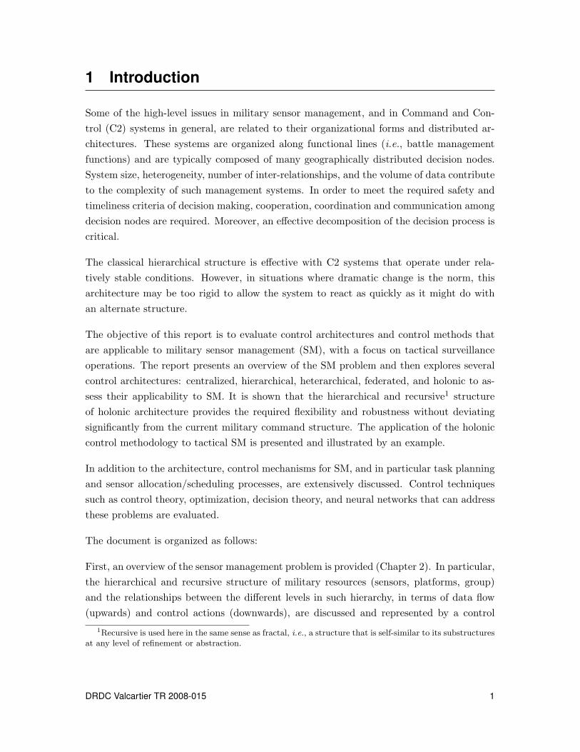
1 Introduction
Some of the high-level issues in military sensor management, and in Command and Con-
trol (C2) systems in general, are related to their organizational forms and distributed ar-
chitectures. These systems are organized along functional lines (i.e., battle management
functions) and are typically composed of many geographically distributed decision nodes.
System size, heterogeneity, number of inter-relationships, and the volume of data contribute
to the complexity of such management systems. In order to meet the required safety and
timeliness criteria of decision making, cooperation, coordination and communication among
decision nodes are required. Moreover, an effective decomposition of the decision process is
critical.
The classical hierarchical structure is effective with C2 systems that operate under rela-
tively stable conditions. However, in situations where dramatic change is the norm, this
architecture may be too rigid to allow the system to react as quickly as it might do with
an alternate structure.
The objective of this report is to evaluate control architectures and control methods that
are applicable to military sensor management (SM), with a focus on tactical surveillance
operations. The report presents an overview of the SM problem and then explores several
control architectures: centralized, hierarchical, heterarchical, federated, and holonic to as-
sess their applicability to SM. It is shown that the hierarchical and recursive1 structure
of holonic architecture provides the required flexibility and robustness without deviating
significantly from the current military command structure. The application of the holonic
control methodology to tactical SM is presented and illustrated by an example.
In addition to the architecture, control mechanisms for SM, and in particular task planning
and sensor allocation/scheduling processes, are extensively discussed. Control techniques
such as control theory, optimization, decision theory, and neural networks that can address
these problems are evaluated.
The document is organized as follows:
First, an overview of the sensor management problem is provided (Chapter 2). In particular,
the hierarchical and recursive structure of military resources (sensors, platforms, group)
and the relationships between the different levels in such hierarchy, in terms of data flow
(upwards) and control actions (downwards), are discussed and represented by a control
1Recursive is used here in the same sense as fractal, i.e., a structure that is self-similar to its substructuresat any level of refinement or abstraction.
DRDC Valcartier TR 2008-015 1
loop, which describes in detail the essence of the SM problem.
Next, we evaluate the full spectrum of system architectures, ranging from centralized to
fully distributed, with respect to the issue of SM (Chapter 3).
In Chapter 4, control and coordination techniques that can best address SM problems are
reviewed and evaluated.
Chapter 5 presents the general concept of holons and the characteristics of holonic organi-
zations. Related work on holonic systems, in particular in the manufacturing domain, is
presented. In the last part, similarities and differences between holonic systems and Multi-
Agent Systems (MAS) and the use of agent technology for implementation of a holonic
system are discussed.
In Chapter 6, the application of holonic architecture to SM systems is shown and control
aspects of SM are investigated in more details. It is demonstrated that the functional
elements of SM can address the varying sensing requirements at each and every level in the
hierarchy.
Concluding remarks, recommendations, and subsequent work are presented in Chapter 7.
2 DRDC Valcartier TR 2008-015
2 Sensor management: An overview
The military operations are typically conducted in demanding, dynamic, semi-structured,
and large-scale environments. The nature of this operating environment makes it difficult
to detect, identify, and monitor all the targets within the Volume of Interest (VOI). To
deal with this problem, sensing resources have to be distributed across a large geographical
area. Military platforms, such as ships, planes, and helicopters, can be outfitted with sensing
resources, which can potentially provide a wealth of data. Yet, to be effectively used, these
sensing resources need to be properly managed [1]. Historically, interpreting the data and
managing the sensors were done manually, however, these tasks have become difficult, if
not impossible, due to the constantly increasing complexity of modern surveillance systems.
As tactical surveillance sensors increase in complexity and capabilities, such as the new
Electronically Scanned Array (ESA), management of sensing resources becomes more and
more challenging, so innovative methods will have to be utilized in order to make effective
use of these new surveillance tools. Sensor management (SM) is an automated process that
optimizes the utilization of the sensing resources and improves the quality of the acquired
data, leading ultimately to a better situation analysis.
2.1 Command and data flow
The military has a hierarchical Command and Control (C2) structure to manage its tactical
resources (sensors and weapons), personnel, and non-tactical equipments. Sensor manage-
ment (SM), a subset of this structure, is not only hierarchical, but also exhibits a recursive
structure as shown in Figure 1 for a typical naval task force [1]. This figure illustrates a
task force where a central command directs a group of platforms, each of which controls a
number of sensing resources or other subsidiary platforms. In this pyramidal structure, the
chain of command flows from the top to the bottom levels.
SM is an element of the decision process that governs the overall behaviour of the sensing
resources, at all levels. It receives sensing objectives from a superior level in the hierarchy
and then develops sensing priorities considering the current situation. These priorities are
used to allocate available resources to the surveillance tasks. Tasks such as tracking an
enemy target that is displaying a hostile behaviour would receive a higher priority than
performing a general survey of a certain VOI that is unlikely to contain any High Interest
Target (HIT). Tasks are prioritized based on the tactical needs of the platform, the group
of platforms, and/or the force, which are, respectively: achieving local objectives and self-
defence, achieving mission regional objectives and group protection, and achieving global
mission objectives.
DRDC Valcartier TR 2008-015 3

Task
Group 1
Platform 1(e.g., Halifax Class)
Platform 2 (e.g., Iroquois
Class)
Platform 3(e.g., CP-140)
Platform 1.2(e.g., CH-124)
Sensor 3.2(e.g., sonabouy)
Task Force
Sensor 3.1(e.g., Radar)
Sensor 2.1(e.g., Radar)
Sensor 1.1(e.g., Radar)
Sensor 1.2.2(e.g., Radar)
Sensor 1.2.1(e.g., Radar)
Mode 1.2.2a Mode 1.2.2b
Task
Group 2
Figure 1: Hierarchy of naval sensing resources
The hierarchical relationship between the sensing resource levels follows the command struc-
ture. Decision processes occur at each level based on the requirements that flow down from
the level above and the information derived from the level below. As one descends the
tiers in the hierarchy, the level of responsibility becomes more focused and the volume of
data increases. As data move up the hierarchy, they are transformed into information that
enables high-level planning and decision making.
As shown in Figure 2, the product of the sensing resources, the data, flows upwards from
the sensors to the top level of the pyramid.
Sensor data delivered upwards in the hierarchy are gathered at each junction (node) and
fused (refined). The idea is that the quality of the information is improved as it moves up
the chain of command. The fusion process at each level of the hierarchy is different due
to the differing levels of abstraction involved. As an example, consider the platforms 1, 2,
and 3 in Figure 1 as frigates equipped with ESA-type sensors and under the command of
a task group commander. In this situation, the sensors produce track estimates of targets
4 DRDC Valcartier TR 2008-015

Fusion
Fusion Fusion Fusion
Sensor SensorSensor Sensor SensorSensor Sensor SensorSensor
Group
Mission
Objectives
Platform
Mission
Objectives
Platform
Mission
Objectives
Platform
Mission
Objectives
Figure 2: Fusion hierarchy
that they detect. At the platform level, the fusion process consists (partly) in refining these
target tracks and assessing threats or other information important to the mission objectives
of that platform. The output of this fusion process is a situation analysis that is specific to
the platform.
Situation analysis at platform-level may not provide a broad or clear enough assessment
of the situation for the task group commander. This situation can occur, for example,
when the platforms are distributed over a large area and none of the platforms is by itself
capable of sensing over the whole region. For such a reason, the situational assessments of
the individual platforms are themselves fused at the group level. This fusion process differs
from platform-level fusion in terms of level of abstraction and goals of the process. The role
of mission objectives in the fusion process is highlighted in Figure 2. One may think of the
global mission objective as being broken down into sub-objectives that are assigned to the
platforms.
Just as the fusion process changes at each successive level of the hierarchy, so does the
management of sensors. As part of the fusion process, SM is responsible for directing sensing
resources to gather the best information that is possible in as short a time as possible. At
the platform level for instance, the SM process may be responsible for controlling sensors
directly through task assignment and scheduling. At the group level, however, SM treats the
platforms themselves as resources and is concerned with issuing somewhat more abstract
sensing objectives to them. That may, for instance, specify a surveillance region for a
certain platform without specifying which sensors to use or how to use them. In this way,
the control of the sensing resources is broken down into smaller more specific tasks at each
level of the hierarchy.
DRDC Valcartier TR 2008-015 5
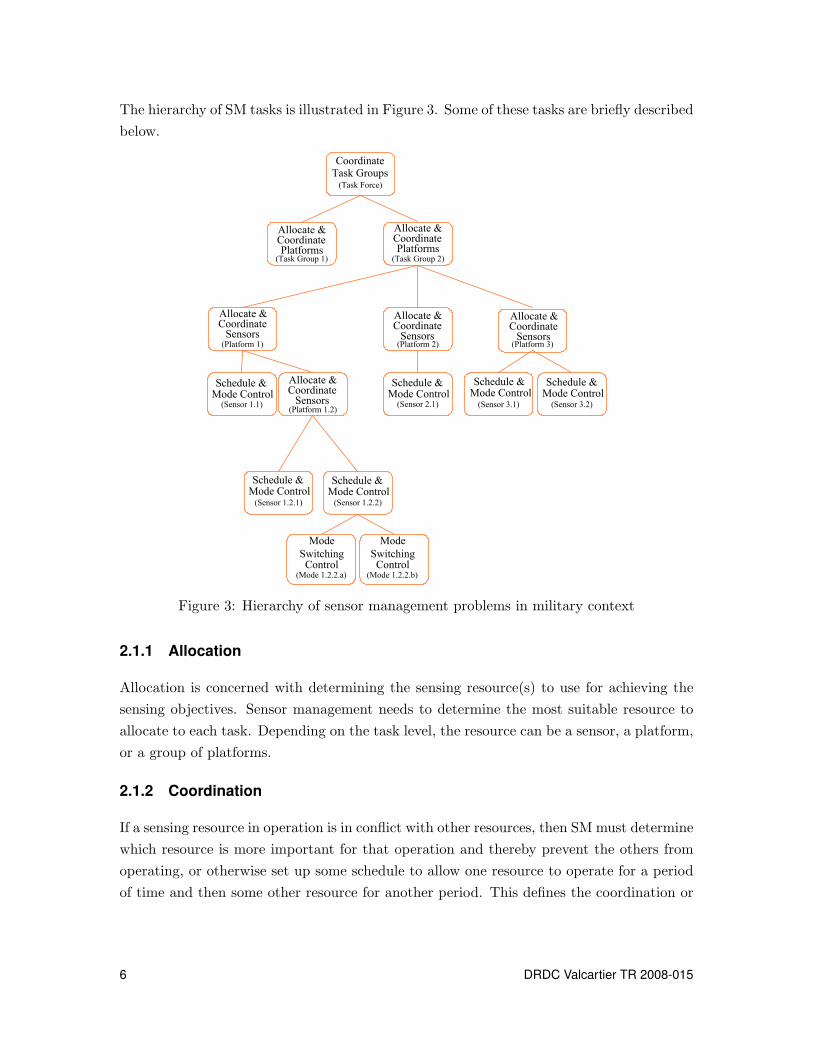
The hierarchy of SM tasks is illustrated in Figure 3. Some of these tasks are briefly described
below.
Allocate &CoordinatePlatforms
(Task Group 2)
Allocate &Coordinate
Sensors(Platform 1) (Platform 2) (Platform 3)
Schedule &Mode Control
(Sensor 1.1)(Platform 1.2)
(Sensor 3.2)
(Sensor 1.2.1) (Sensor 1.2.2)
CoordinateTask Groups
(Task Force)
(Sensor 3.1)(Sensor 2.1)
Mode
SwitchingControl
(Mode 1.2.2.a)
(Task Group 1)
Allocate &CoordinatePlatforms
Allocate &Coordinate
Sensors
Allocate &Coordinate
Sensors
Allocate &Coordinate
Sensors
Schedule &Mode Control
Schedule &Mode Control
Schedule &Mode Control
Schedule &Mode Control
Schedule &Mode Control
Mode
SwitchingControl
(Mode 1.2.2.b)
Figure 3: Hierarchy of sensor management problems in military context
2.1.1 Allocation
Allocation is concerned with determining the sensing resource(s) to use for achieving the
sensing objectives. Sensor management needs to determine the most suitable resource to
allocate to each task. Depending on the task level, the resource can be a sensor, a platform,
or a group of platforms.
2.1.2 Coordination
If a sensing resource in operation is in conflict with other resources, then SM must determine
which resource is more important for that operation and thereby prevent the others from
operating, or otherwise set up some schedule to allow one resource to operate for a period
of time and then some other resource for another period. This defines the coordination or
6 DRDC Valcartier TR 2008-015

conflict resolution problem. Dual to this is the cooperation problem, where synergy among
complementary resources is maximized, as described in the next subsection.
2.1.3 Cooperation
The management of the sensors may require that different sensors work together to acquire
measurements on a common target. This, for instance, consists in dynamically tasking some
sensors to fill the coverage gaps of other sensors, and therefore provide relevant observations
in the areas of tactical interest.
In surveillance applications, there are two primary cooperative functions: the cueing and
the hand-off. The cueing (Figure 4) is the process of using the detections (i.e., contact-level
cueing) or tracks (i.e., track-level cueing) from a sensor A to point another sensor B towards
the same target or event. The hand-off (Figure 5) occurs when sensor A has cued sensor B
for transferring the surveillance or the fire-control responsibility from A to B.
Hence, the response time and performance of sensor B may be improved by providing it with
the detections, the measurements, or the tracks from sensor A with different characteristics.
This may also be used to ensure a continuity of the tracking, when a tracked target passes
out of the (spatial/temporal) coverage of a sensor A to enter the coverage of a sensor B.
Cue Event
(Time & Location)
non-tracked
interval
Sensing Domain
Sensor A
Sensing Domain
Sensor B
Sensor Overlap Region
Figure 4: Target cueing
DRDC Valcartier TR 2008-015 7

Sensing Domain
Sensor A
Sensing Domain
Sensor B
Handoff Event
(Time & Location)
Sensor Overlap Region
Cue Event
(Time & Location)
Figure 5: Target hand-off
2.1.4 Scheduling
Scheduling is the designation of time segments for specific tasks or activities, the nature of
which is defined during the allocation or coordination tasks. Scheduling typically uses time
as its base variable; tasks are expected to start at a specified time and to be executed for
a fixed time interval.
2.1.5 Mode control
In case of sensors offering multiple modes2, the SM should make use of the most optimal
mode for a given task, providing there is no other overriding reason not to.
2.1.6 Mode switching control
When changing sensor modes, the data stream may be halted during the transition. The
SM must address whether it is more important to maintain the operation in a possibly
sub-optimal mode to capture a live data stream, or to switch to a more optimal mode.
2.1.7 Other SM tactical issues
Other potential issues in tactical surveillance, for which strategies within SM are required
at all levels, would include:
2Modes may represent scan rate, beam width, sensor sensitivity, look angle, detection threshold, etc.
8 DRDC Valcartier TR 2008-015

Emission control – SM system must trade off the use of active sensors for gathering
more complete information over self-security. Active sensing equipment such as radars
may betray their existence by emitting energy, and therefore increase the vulnerability
of the whole surveillance system. The use of such sensors thus needs to be minimized
to control their emission when/where there is a strong requirement on a “silent” radar
work to achieve the Low Probability of Interception feature (so called LPI radar).
The optimization criterion (to be minimized) may be the detectability and/or the
identification of our own sensor suite. Controlling the emitted power, its duration,
and the spatial coverage of the active sensors can be used to reduce the emission.
Failure recovery – SM must alter the sensing allocation and schedule in case of
disabled or diminished sensing capability.
Contingency handling – SM must address when and how to make the necessary
changes if the situation or objectives change.
Countermeasure handling – that aims at reducing the effects of the countermea-
sures (deception, jamming, exploitation) on the performance of the sensor suite. This
task essentially concerns the Electronic Counter-Counter-Measure (ECCM) that aims
at taking actions to protect sensors from any effect of friendly or enemy usage of an
electronic warfare that degrades, neutralizes, or destroys the friendly combat capabil-
ity.
Operator input – Since in the C2 context, the ultimate authority and responsi-
bility belong to the human operators, the management system must allow for their
commands and preferences to be taken into account. Therefore, the SM system must
provide an interaction interface with the operators.
2.2 Control in the hierarchy of resources
The SM system at each level makes decisions on how to most effectively use the sensing
resources under its direction to achieve the tasks requested by the level above while ad-
dressing a changeable working environment. This mechanism generates commands (control
actions) to resources within its purview. These sensor control actions are based on external
inputs from the level above, the feedback regarding the changes in the environment, and
the SM system’s performance. Control challenges at each level differ from each other, but
maintain a constant scheme as depicted in Figure 6.
The sensor control system must also be capable of addressing two types of data timing: data
that are generated at regular time intervals (synchronous) and data that are generated at
DRDC Valcartier TR 2008-015 9

Threat Evaluation(High Level Data Fusion)
Sensing
Resource
a priori
Information
Tracking(Picture Compilation)
Sensor Scheduling
&
Mode Control
To decision-making
level
Sensing
Resource
Sensing
Resource
Sen
sor
Con
tro
l
Sensor data
a priori Information
Low-level fused
information
Sensor Allocation
&
Coordination
From decision-
making Level
Low-level sensing priorities
Threat level
a priori Information
Figure 6: Closed-loop sensing
irregular time intervals (asynchronous) in response to external events. Chapter 4 of this
document provides a review of control techniques suitable for action selection in SM.
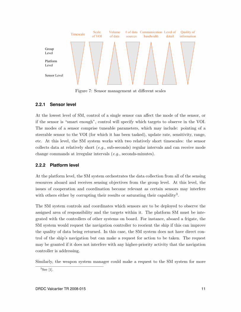
As shown in Figures 3 and 6, different levels in the management of sensors have similar
characteristics and perform similar tasks, yet, at different scales. Figure 7 illustrates how,
for each feature, the scale varies depending on the level of management in the hierarchy. For
instance, the timescale at which the group level operates is much more long-term than that
of the sensor level. At the platform level, sensors may function internally at the minute
[min] level and report to the group level at the hour [h] timescale. On the other hand,
the sensor itself functions internally at the millisecond [ms] timescale and reports to the
platform level at the second [s] timescale.
Figure 8 illustrates the scope of control of the SM system at each level of the command
hierarchy and the type of feedback received from inferior levels.
10 DRDC Valcartier TR 2008-015
Group
Level
Platform
Level
Sensor Level
Scale
of VOI
Volume
of data
# of data
sourcesTimescale
Communication
bandwidth
Quality of
information
Level of
detail
Figure 7: Sensor management at different scales
2.2.1 Sensor level
At the lowest level of SM, control of a single sensor can affect the mode of the sensor, or
if the sensor is “smart enough”, control will specify which targets to observe in the VOI.
The modes of a sensor comprise tuneable parameters, which may include: pointing of a
steerable sensor to the VOI (for which it has been tasked), update rate, sensitivity, range,
etc. At this level, the SM system works with two relatively short timescales: the sensor
collects data at relatively short (e.g., sub-seconds) regular intervals and can receive mode
change commands at irregular intervals (e.g., seconds-minutes).
2.2.2 Platform level
At the platform level, the SM system orchestrates the data collection from all of the sensing
resources aboard and receives sensing objectives from the group level. At this level, the
issues of cooperation and coordination become relevant as certain sensors may interfere
with others either by corrupting their results or saturating their capability3.
The SM system controls and coordinates which sensors are to be deployed to observe the
assigned area of responsibility and the targets within it. The platform SM must be inte-
grated with the controllers of other systems on board. For instance, aboard a frigate, the
SM system would request the navigation controller to reorient the ship if this can improve
the quality of data being returned. In this case, the SM system does not have direct con-
trol of the ship’s navigation but can make a request for action to be taken. The request
may be granted if it does not interfere with any higher-priority activity that the navigation
controller is addressing.
Similarly, the weapon system manager could make a request to the SM system for more
3See [1].
DRDC Valcartier TR 2008-015 11
information about a particular target. At this level, the latter and the data fusion process
must deal with multiple data streams from sensors. Each sensor aboard the platform will
report its observations at regular time intervals (e.g., seconds); however, not necessarily at
the same data rate. The fusion process must integrate data both spatially and temporally.
The data collected can also include an irregular data stream such as a new target detected.
Sensing objectives from the group level are received on an irregular basis (e.g., minutes-
hours).
2.2.3 Group level
The group-level SM involves the control and coordination of platform sensing resources to
monitor a specific VOI and possibly to track a set of known targets. At this level, the SM
system must resolve conflicts between platforms such as: electromagnetic emission conflicts,
a platform occluding the view of another, or a platform interfering with the navigation of
another. The group-level SM system receives sensing objectives from the force/coalition
level4 irregularly (e.g., hours-days), but will receive observation reports from its platforms
on a regular basis (e.g., minutes) and will report its observations to the force/coalition level
regularly (e.g., hours) too.
2.2.4 Control structure
As a result of the hierarchical command structure, the fusion process and therefore the
SM process is hierarchical in nature. Moreover, if one thinks of the platform as a resource
for the management at the group level, then one can see that the SM system is not just
hierarchical but also recursive. This hierarchical and recursive5 nature is illustrated in
Figure 1 representing a set of platforms and a group-level SM system interacting with all of
them and their sensors. As an example, the platform resources could be frigates with their
own internal C2. The group-level C2 could be a remote command centre, another military
platform such as a destroyer, or even a command centre aboard one of the frigates in the
group. If the platforms are viewed as resources for a C2, one can see that the management
of sensors at this level is similar to SM within the platforms themselves. Here, data from
sensor resources (platforms in this case) are fused and analyzed, providing input to the SM
system, which then redirects the sensing resources.
The function of SM at the platform level and the group level differs, but the structure
is hierarchical and recursive. This recursive structure can be extended to management of
groups of platforms (e.g., task forces and multinational coalitions) with exactly the same
4This may also be a shore-based command centre.5In that one platform may be composed of other platforms.
12 DRDC Valcartier TR 2008-015

structure. Force/coalition-level SM coordinates the sensing activities of groups of platforms.
At each level in the hierarchy, the SM systems below it are considered as resources, whether
they are sensors aboard a platform, platforms within a group, or groups within a task
force/coalition.
The decentralized, hierarchical, and recursive nature of this structure will need to be consid-
ered when comes the time to select or design a control architecture for sensor management.
DRDC Valcartier TR 2008-015 13

Sensor Management
(Level n+1)
[platform VOI sector actions
determined]
Sensor Management
(Level n)
[Specific sensor is allocated
to a surveillance task]
Sensor Management
(Level n-1)
[Sensor specific mode
parameters are selected]
[Execute mode requests and return data as collected]
Mode
update rate
range
sensitivity
pointing direction
Contact Data
kinematic data (range &
bearing)
non-kinematic data (id, x-
section, etc.)
Sensing Objectives
sensor VOI (sector to survey)
noted targets of interest in sensor
VOI
sensor operating rules
Platform Sensing Objectives
platform VOI
noted targets of interest in
platform VOI
platform operating rules
Data Fusion
(Level n-1)
[Generation of tracks and
data association for each
contact]
Data Fusion
(Level n)
[Fusion of data from local
multiple sensing resources]
Data Fusion
(Level n+1)
[Fusion of data form multiple
platform sensing resources]
Track Data (1 sensor)
kinematic data (range & bearing)
non-kinematic data (id, x-section,
etc.)
probability
Track information and situation
assessment based on combined
track data from multiple sensors.
Impact assessment based on
combined situation assessments
from multiple platforms.
Group Objectives
group VOI
noted targets of interest in group
VOI
group operating rules
Figure 8: Sensor management levels of responsibility
14 DRDC Valcartier TR 2008-015

3 System architectures
The control architecture of a system defines the organizational behaviour of the nodes that
comprise it and the inter-node communications pathways that enable control and flow of
data. Each node embodies an element of control in the structure. In distributed control
schemes, each node in the architecture has a controller that allows it to work collectively
with its neighbours to achieve some overall goal. Controllers are entities that implement
control through a given method in order to perform certain actions at some local level.
There are several organizational structures that allow nodes and their controllers to work
together for achieving an overall goal.
This question of “system architecture” has led industrial and academic researchers to in-
vestigate a spectrum of decentralized control architectures. These range from hierarchical
decomposition to a completely decentralized6 approach where individual controllers are as-
signed to subsystems and may work independently or may share information, as shown in
Figure 9.
In this section, we summarize the main system architectures that were proposed in the
early work on distributed control systems and then provide an introduction to federated
architectures that motivated much of the work on system architecture for holonic systems.
Let us remind that the decentralized, hierarchical, and recursive nature of the sensor man-
agement structure, as discussed in the previous chapter, requires that its control architecture
presents the following characteristics:
• hierarchical structure to account for a clear chain of command,
• adaptability to the current situation,
• sufficient autonomy of each node to perform its function without being encumbered
by actions taken at the top level,
• sufficient robustness to maintain operations, even if elements of the network are inca-
pacitated or if communication links are severed,
• recursiveness where each node can be composed of one or more nodes of a lower
abstraction level.
In the following, a list of candidate control architectures to address the sensor management
(SM) problem are presented.
6Also referred to as “heterarchical”.
DRDC Valcartier TR 2008-015 15
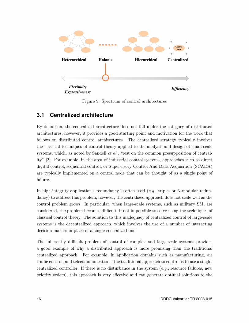
Flexibility
Expressiveness Efficiency
Control
Node
CentralizedHierarchicalHeterarchical Holonic
Figure 9: Spectrum of control architectures
3.1 Centralized architecture
By definition, the centralized architecture does not fall under the category of distributed
architectures; however, it provides a good starting point and motivation for the work that
follows on distributed control architectures. The centralized strategy typically involves
the classical techniques of control theory applied to the analysis and design of small-scale
systems, which, as noted by Sandell et al., “rest on the common presupposition of central-
ity” [2]. For example, in the area of industrial control systems, approaches such as direct
digital control, sequential control, or Supervisory Control And Data Acquisition (SCADA)
are typically implemented on a central node that can be thought of as a single point of
failure.
In high-integrity applications, redundancy is often used (e.g., triple- or N-modular redun-
dancy) to address this problem, however, the centralized approach does not scale well as the
control problem grows. In particular, when large-scale systems, such as military SM, are
considered, the problem becomes difficult, if not impossible to solve using the techniques of
classical control theory. The solution to this inadequacy of centralized control of large-scale
systems is the decentralized approach, which involves the use of a number of interacting
decision-makers in place of a single centralized one.
The inherently difficult problem of control of complex and large-scale systems provides
a good example of why a distributed approach is more promising than the traditional
centralized approach. For example, in application domains such as manufacturing, air
traffic control, and telecommunications, the traditional approach to control is to use a single,
centralized controller. If there is no disturbance in the system (e.g., resource failures, new
priority orders), this approach is very effective and can generate optimal solutions to the
16 DRDC Valcartier TR 2008-015

control and coordination problem.
Most systems are not deterministic, however. Also, many complex systems, such as SM
systems, consist of physically distributed resources that behave in a highly concurrent and
dynamic fashion. As a result, centralized controls quickly become obsolete and must be
either ignored or frequently updated, although this is not always possible if the generation
of control policy and its dissemination time are important.
An alternative approach is to match the control strategy more closely with the physical
system. In other words, the problem can be decomposed so that control and coordination are
performed by many simple, autonomous, and co-operative entities. Rather than following
a pre-determined plan, the control emerges from the interaction of these intelligent entities.
This approach leads to a control system that is “decentralized rather than centralized,
emergent rather than planned, and concurrent rather than sequential” [3]. Additionally,
a distributed intelligent control approach provides the advantages of adaptability, ease of
upgradeability and maintenance, and emergent behaviour. The disadvantages of this co-
operative control approach are that global optima cannot be guaranteed and predictions of
the system’s behaviour can only be made at the aggregate level [3]. However, even with
conventional centralized approaches, global optima often cannot be achieved in practice and
the detailed predictions provided by these systems are frequently invalidated.
3.2 Hierarchical architecture
One of the earliest formal quantitative treatments of the control of large scale systems
that used the hierarchical decomposition method was an extension of organizational theory
by [4]. Their mathematical treatment positioned hierarchical (multi-level) systems theory
with respect to three categories of organizational theory:
Classical – The typical hierarchical structure of organization s is emphasized.
Behavioural – Decision-makers are viewed in a motivational sense (i.e., they are
goal-seeking).
Systemic – It is recognized that decision-making systems consist of collections of
interconnected decision-making subsystems.
The two most prominent structural aspects that are focused by Mesanovic et al. in [4] are
specialization and coordination of the components that make up the system (i.e., the entities
or decision-makers). Coordination of the specialized entities in these systems could be
achieved either by “analytical processes” (i.e., problem solving) or by “bargaining processes”
DRDC Valcartier TR 2008-015 17
such as in economic systems. Initially, the present work was restricted to open-loop control
of continuous time, deterministic systems, but extensions of the topic found in Singh [5]
and Jamshidi [6] enabled the consideration of closed-loop control of simple discrete-time
stochastic systems.
The basic characteristics of the hierarchical systems considered in this approach can be
defined as follows:
- decision-making units are arranged in a pyramid-like structure “where at each level,
a number of such units operate in parallel” [5];
- the system has an overall goal; the goals of each of the decision-making units should
be in harmony with the overall goal;
- an iterative exchange of information occurs between the decision-making units where
the higher level units have “right of intervention” over the lower level units, and the
upwards-oriented feedback and response to intervention of the lower level units creates
a “performance interdependence” between upper and lower levels [4];
- the time horizon increases as one goes up the levels of the hierarchy.
The hierarchical approach to the control of large-scale systems involves decomposing an
overall system into small subsystems that have weak interactions with each other. Early
work in the area of hierarchical decomposition used mathematical programming techniques
such as those described by Dantzig and Wolfe in [7] to decompose complex problems into
smaller, more manageable ones. The two most common approaches to this technique are
spatial separation (i.e., the multi-level technique described by Mesanovic et al. in [4] and
Singh in [5]), and temporal separation (i.e., the multi-layer, or frequency decomposition
approach described by Gershwin in [8] and Jones and Saleh in [9]). These approaches are
defined as follows:
Multi-level – This approach involves the decomposition of a “complex control prob-
lem into a series of smaller and simpler subproblems” [9]. A “decoupled” approach is
used to solve the global problem [6]: sub-problems are solved independently and the
overall system solution is obtained by coordination.
Multi-layer – This approach uses a frequency separation methodology that involves
the clustering of events that occur at similar frequencies together. Control is then
split into algorithms that operate on different time scales.
18 DRDC Valcartier TR 2008-015

Multi-level decomposition of the control problem has its origins in solutions to mathematical
programming problems [7, 10, 11], as well as the early work on production planning [12].
For example, spatial decomposition of the control problem has been accomplished by a
physical clustering of equipment as exposed by Albus et al. [13], as well as by a more
abstract division of the problem into decision spaces as proposed by Jones and Saleh [9].
It has been implied in the literature that hierarchical architectures are rigid and prone to
deadlock if a failure occurs at some level [14, 15]. In order to achieve the overall system goal
in the models described in Mesanovic et al. and Singh [4, 5], a hierarchy of controllers acting
as parallel decision-makers must solve the local control problems of each of the subsystems
independently. Meanwhile, a higher level controller coordinates the local controllers in an
iterative fashion in order to achieve an overall system control [5]. This means of control
does not seem to imply a rigid structure that might result in a catastrophic failure if
a local controller fails, what suggests that criticisms of hierarchical approaches may be
unfounded [14].
One point in the defense of hierarchical systems offered by Jones and Saleh [9] is that there is
a misconception about peer-to-peer relationships in these systems (i.e., many people believe
that hierarchical systems generate master/slave relationships and do not allow peer-to-peer
relationships). As noted in [9], hierarchical systems are capable of peer-to-peer relationships
as long as data flow is not equated with control flow. In other words, if data communication
can be kept separate from the control structure, peer-to-peer relationships are possible.
Recent research has shown that hierarchical relationships can exist without restrictions
on the amount of peer-to-peer communication. Examples include contract net [16, 17],
intelligent agent systems [18], and holonic systems [19]. In the next sections, we look at
some of the early works in these areas.
3.3 Heterarchical architecture
Much of the early work on non-hierarchical, or heterarchical, control architectures is based
on the concept of Distributed Data Processing Systems (DDPS) described by Enslow [20].
The basic definition that is given for a DDPS is that the system must support a “high
degree of distribution in all dimensions, as well as a high degree of cooperative autonomy”.
The dimensions of distribution referred to are:
Hardware – The amount of distribution shown by processing resources.
Control – The degree of cooperation between processing resources. Ranges from mul-
tiple resources that are fully cooperating through resources that exhibit master/slave
relationships to a single fixed resource.
DRDC Valcartier TR 2008-015 19

Database – The degree of distribution of data.
Cooperative autonomy is defined [20] as the ability of “any resource, either physical or
logical, to refuse the transfer or acceptance of a message based on its own knowledge of its
own status” and contrasted with the strict master/slave relationship that forces the slave to
accept a message. This definition of autonomy implies that there is no enforced hierarchy
of control in the system which, as it will be seen later in this chapter, is not strictly the case
with cooperative strategies (e.g., the contract net). The concept of cooperative autonomy
is applied to a wide range of complex systems [21, 22].
In [22], Hatvany’s view of systems ranges from highly centralized hierarchies, which may
lead in due course to catastrophic collapse, to completely autonomous systems that are akin
to anarchy. The answer that is proposed is a type of cooperative autonomy: heterarchies
(i.e., heterarchical networks) of systems that can be dynamically reconfigured. Although
the ideas presented by Vamos [21] and Hatvany [22] do not offer concrete methods for
implementation, they have provided the incentive for research in the area of non-hierarchical
control.
As the term cooperative autonomy implies, the central concern in this area is how au-
tonomous decision-makers in a non-hierarchical system can interact effectively. Various
approaches have been taken to achieve the goal of cooperative autonomy. The majority
of the work in this area is based on the negotiation metaphor and has stemmed from the
work presented by Davis and Smith [16] on distributed sensor systems. Their distributed
problem-solving approach requires the “cooperative solution of problems by a decentralized,
loosely coupled collection of problem solvers” [16] and differs from distributed computing
in that it is concerned with a single task envisioned for the system; the goal is to create an
environment for cooperative behaviour.
The contract net protocol [23] has been developed to deal with distributed problem-solving
by:
- distributing the problem by decomposing it into smaller subtasks that are distributed
among a group of decision-makers,
- creating an environment where decision-makers with problems can find decision-
makers with answers, and
- establishing a contract net of managers and contractors as described below.
When a decision-maker assumes the role of manager, it monitors the execution of a task
and processes the results of its execution; when a decision-maker is required to become a
20 DRDC Valcartier TR 2008-015
contractor, it is responsible for the execution of the task assigned to it by a manager. An
interesting result of the contract net is that the dynamic “manager/contractor arrangement
leads to the hierarchical control structure that is typical of task sharing [16].
The work presented by Parunak in [17] uses the concept of the contract net and moves
it from the information domain to the manufacturing domain with the development of
the YAMS (Yet Another Manufacturing System) software. This system uses the same
concepts of manager and contractor as those introduced by Davis and Smith to achieve
the coordination of a network of distributed computing nodes. The YAMS system uses an
open system model that allows for the addition and removal of agents; also, it separates the
knowledge base from the control structure through information hiding.
Parunak notes that two anomalies can occur when this type of system is used for manufac-
turing system control: (i) temporal ignorance, and (ii) compromise anomaly [17]. The first,
temporal ignorance, is concerned with decision-makers only seeking task announcements
and bids that have already arrived, not those about to arrive. As a result, by committing
itself too early to a task, a decision-maker may commit resources that cannot be used to bid
on a more convenient task that arrives later. The second anomaly, compromise anomaly,
is related to the amount of global information that decision-makers use. Since decision-
makers do not have access to global information, they may make decisions that are locally
advantageous (i.e., are advantageous for the situation at hand) but do not result in global
advantage (i.e., are not the best decision for the overall problem).
The work by Duffie et al. [24, 25] focuses on a non-hierarchical opportunistic scheduling
technique for machining cell control. The characteristic of this approach that sets it apart
from traditional hierarchical control structures, is that part flow is achieved by part-oriented
requests as opposed to machine-oriented requests. To achieve part-oriented scheduling, the
supervisory functions are distributed through the system and a scheduling algorithm is
implemented at each decision-making node of the system, resulting in a system where:
- There are no permanent master/slave relationship.
- Decision-makers may cooperate through communication to achieve individual and
system wide goals.
- Global information is minimized (i.e., information is localized as far as possible).
Work in this area has served as a catalyst for research on extending concepts from the
field of Multi-Agent Systems (MAS) to various large-scale systems. However, despite the
benefits of a purely distributed or heterarchical approach, there are also many drawbacks. In
DRDC Valcartier TR 2008-015 21

particular, the disadvantages of this approach are that global optima cannot be guaranteed
and predictions of the system’s behaviour can only be made at the aggregate level [3].
However, even with conventional centralized approaches, global optima often cannot be
achieved in practice and the detailed predictions provided by these systems are frequently
invalidated.
In the next section, we look at an approach that combines the benefits of hierarchical and
heterarchical architectures.
3.4 Federated architecture
As illustrated in Figure 9 and implied by their titles, the hierarchical and heterarchical
architectures lie at opposite ends of the distributed control architectures spectrum7. The
hierarchical approach is rigid and suffers from many of the shortcomings of the centralized
approach, yet it offers clear advantages in terms of overall system coordination; alternatively,
the heterarchical approach is flexible and fault-tolerant, but, arguably difficult to coordinate.
Federated architectures are increasingly being considered as a compromise between these
two extremes, particularly in the area of control of large-scale systems. Like heterarchical
architectures, federated architectures have no explicit shared facility for storing data, i.e.,
data are stored locally. The structure of a federated architecture is achieved through mes-
sage passing between agents and specialized agents called middle agents. In this section, we
summarize five main federated architecture approaches that appear in the MAS literature:
(i) the facilitator approach, (ii) the broker approach, (iii) the matchmaker approach, (iv)
the mediator approach, and (v) the holonic approach.
3.4.1 Facilitator
As the name implies, the facilitator approach utilizes a specialized agent called a facilitator
to coordinate groups of agents, as illustrated in Figure 10. This approach was first proposed
by McGuire et al. for their SHADE project [26], where facilitator agents were used to pro-
vide a reliable network communication layer, route messages, and coordinate the control
of multi-agent activities. A key characteristic of this approach is that communication and
coordination are facilitated by the middle agents, i.e., facilitator agents and agents com-
municate with each other, facilitator agents communicate with each other, but individual
agents do not communicate with each other. In other words, agents do not direct their
messages to other agents, but rely on facilitator agents to route their messages to agents
7Note that the centralized architecture, which is at extreme right of the spectrum, is excluded from thedistributed control architectures, since, by definition, it cannot be distributed.
22 DRDC Valcartier TR 2008-015

that are able to handle them. This may involve translating the message, decomposing the
problem, and allocating the sub-problems.
Messages between
facilitators
Facilitator Facilitator
FacilitatorAgent
Agent
Agent
Agent
Agent
Agent
Agent
Agent
Agent
Agent
Agent
Figure 10: Facilitator approach
3.4.2 Broker
The broker approach, illustrated in Figure 11, uses a specialized agent to find suitable
agents for a particular task [27]. The main difference with the facilitator approach is that
all agents in the broker architecture may contact all brokers to find service agents; agents
in the facilitator architecture must communicate through its single facilitator agent only.
3.4.3 Matchmaking
The matchmaking approach, illustrated in Figure 12, uses brokering mechanisms to match
agents together, however it goes one step further by allowing these agents to be directly
linked. Once this link is established, the matchmaker agent removes itself from the group
and allows the remaining agents to proceed with communication. An important applica-
tion of this approach is that of internet information retrieval [28]. This approach is often
manifested with so-called yellow-pages agents, which can be thought of as a variation of the
matchmaker agent. In this case, however, an explicit mechanism is required to allow agents
to register their services on an agent services directory or yellow-pages.
DRDC Valcartier TR 2008-015 23

Broker 1
Agent
Agent
Agent
Agent
Agent
Agent
Broker 3
Broker 2
Client Agents Client AgentsBroker Agents
Figure 11: Broker approach
Agent
AgentAgent
Matchmaker
Agent
AgentAgent
Figure 12: Matchmaking approach
3.4.4 Mediator
The mediator approach shares many of the characteristics of the three federated architec-
tures discussed previously, but brings an additional coordination role to the table. Mediator
agents use brokering and matchmaking mechanisms to help agents find other agents to es-
tablish collaborative subsystems of agents, or “coordination clusters”. Once these clusters
of agents are established, the mediator’s role is expanded to include mediation behaviours,
which focus on high-level policies for situations such as breaking decision deadlocks. Early
work on the mediator approach was conducted by Wiederhold [29] and Gaines et al. [30].
3.4.5 Holonic
The holonic approach [31] is very similar to the mediator to which it adds a recursive
(fractal-like) structure (see Figure 13). This defines a hierarchy of mediator-based levels
24 DRDC Valcartier TR 2008-015
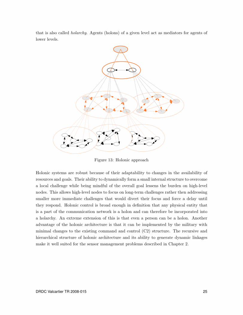
that is also called holarchy. Agents (holons) of a given level act as mediators for agents of
lower levels.
Figure 13: Holonic approach
Holonic systems are robust because of their adaptability to changes in the availability of
resources and goals. Their ability to dynamically form a small internal structure to overcome
a local challenge while being mindful of the overall goal lessens the burden on high-level
nodes. This allows high-level nodes to focus on long-term challenges rather then addressing
smaller more immediate challenges that would divert their focus and force a delay until
they respond. Holonic control is broad enough in definition that any physical entity that
is a part of the communication network is a holon and can therefore be incorporated into
a holarchy. An extreme extension of this is that even a person can be a holon. Another
advantage of the holonic architecture is that it can be implemented by the military with
minimal changes to the existing command and control (C2) structure. The recursive and
hierarchical structure of holonic architecture and its ability to generate dynamic linkages
make it well suited for the sensor management problems described in Chapter 2.
DRDC Valcartier TR 2008-015 25
3.5 Summary
Control and coordination have evolved from a highly centralized model, where an individ-
ual or a software agent develops a fairly rigid control policy to a decentralized approach.
This centralized control is simple to implement and can generate a near optimal solution;
however, it is not robust for operation in a dynamic and uncertain environment.
In contrast, the decentralized approach is well suited to dynamic, non-deterministic, and
uncertain environments. This approach makes use of resources as they become available, re-
sulting in an easy-going and dynamic balancing of workload (i.e., dynamic reconfiguration).
The decentralized model allows resources to make local decisions to maintain operations.
This enables the system to operate as a whole, but faces the challenge of coordination. Re-
sources act as autonomous agents and the system functions, provided that it is sufficiently
constrained to prevent too many outside events from influencing the outcome. This ap-
proach makes directed effort (i.e., deliberative behaviour) difficult, because it is essentially
market-driven (i.e., responds to events that provide the most local benefit). To expedite
an event or action by a resource, the coordinator must override the local market by placing
a higher value on the action or devaluing the normal work. Fully decentralized control
and coordination of activities allows for robust operation, but limits the ability to redirect
operations.
Federated architectures offer a compromise between the hierarchical and the heterarchical
structures. Like the heterarchical approach, the nodes have a high degree of autonomy but
communicate through specialized middle nodes. Most of federated architectures, including
facilitator, broker, matchmaker, and mediator, offer improved robustness and flexibility
over other architectures, yet only the holonic architecture allows for dynamic restructuring.
The holonic architecture, discussed in detail in Chapter 5, has a hybrid structure that takes
the best of different architectures and avoids many of their pitfalls. It takes advantage of
the distributed capabilities of classical Multi-Agent Systems (MAS) while incorporating the
benefits of the hierarchical command and control (C2) structure that allows for strong goal
orientation.
26 DRDC Valcartier TR 2008-015
4 Control and coordination techniques
Control and coordination are decision processes that must be designed with respect to
each individual sensor management (SM) system. Techniques applicable to the control and
coordination problem may be considered separately from the architecture in which they
are implemented, and this is the focus of this chapter. For discussion purposes, it is useful
to refer to the control and coordination problem as an action selection problem, and the
architecture in which it is implemented as the control architecture.
The role of the control and coordination process is to generate actions or commands based
on the state of the sensing resources, the information gathered from these sensing resources,
and external inputs such as commands or stated goals. We assume a discrete time controller
that generates a set of actions a(k) for each time step k. In this context, the control strategy
can be thought of as a mapping from inputs to actions. If we define the current state of
the sensors as x(k), the current sensor readings as s(k), and the external inputs as e(k), we
can define the control problem as the mapping of inputs to actions
a(k) = f
[
a(k − 1), x(k), x(k − 1), . . . x(k − n), s(k), s(k − 1), . . . s(k − m), e(k)
]
(1)
Note that, as shown by equation 1, in this most general form, the action selection may
depend on past sensor states (n > 0) as well as past sensor readings (m > 0). However,
action selection relies only on the most recent external (command) input.
The control and coordination problem as stated here combines the role of the task planner
with the allocation/scheduling module8 into a single entity. Related to the role of SM pre-
viously described, the output a(k) of the function f above is the allocation or scheduling
command issued to the sensing resources. At the group level, these would include sens-
ing directives issued to the platforms, while at the platform level, the control commands
would be more specific (i.e., mode selection, sensor allocation, etc.). In this general form,
task planning and sensor allocation are computed simultaneously, although in a practical
implementation, some degree of separation between these two aspects may be necessary.
A number of different methods exist for specifying the control function f . The simplest
approach is to explicitly define an action for every conceivable input condition, a lookup-
table solution. This approach is practical only for the most modest control problems as
the number of input conditions can be quite large when networks of sensors are considered.
A more reasonable approach is to derive the function f and simply compute the actions,
8Described in Chapter 6.
DRDC Valcartier TR 2008-015 27

a(k), at each time step k. This can be accomplished in a number of ways as outlined in the
following sections.
While the control and coordination strategy and the control architecture can be treated in-
dependently, it is generally advantageous to design both simultaneously. In most problems,
there is a natural division of labour into active components that should be addressed with
the control architecture. Such divisions are made on the basis of time-scales of operation,
physical locations, or communication limitations. It is generally easier to meet performance
specifications by breaking the problem into smaller pieces and addressing control within
each of these pieces independently.
4.1 Classical control theory
The SM problem can be viewed as a control problem, as illustrated in Figure 14. The set
of sensing resources together are considered as the plant, i.e. the system to be controlled.
The SM system itself constitutes the controller. External inputs to the system can also
be modeled. High-level commands are treated as reference inputs and constraints, while
new developments in the environment are treated as perturbations to the system of sensors.
Metrics or evaluations of the performance of the system are “fed” back to the controller and
compared with the reference inputs and previous values that in turn generate new controller
actions. This is the feedback model of control.
Control Sensor Suite Metrics+
-1
EnvironmentConstraints
Observed performance
Desired
Performance
Actions
Figure 14: Sensor management as a control problem
Feedback control theory has been extensively studied in the literature although there is
relatively little work done on adapting this theory to SM [32, 33]. Feedback control is
well suited to SM at the resource level, as it naturally addresses the negotiation between
deliberative and reactive objectives. In addition, feedback control of this type is suited for
the near real-time control that is generally required at the resource level. In managing the
pointing of a radar detector for example, control objectives may specify a desired position
and the feedback loop would implement the appropriate motor responses.
28 DRDC Valcartier TR 2008-015

The most basic type of feedback control is proportional feedback. In this approach, the
control is adjusted in proportion to the difference between the desired performance and
the actual performance. Choice of the feedback gain is the central difficulty with this ap-
proach; too small a gain leads to poor performance while too high a gain leads to instability.
One significant advantage of this type of control is that it can be implemented by electri-
cal/mechanical devices rather than digitally, making it suitable for real-time applications.
In the control theory approach, the control strategy is based largely on the sensor readings
that are fed-back via computed metrics. The state of the sensors may also be fed-back
directly or may be incorporated in the calculation of the metrics. Metrics may be based
only on previous time-step information or may include past state and sensor readings. The
behaviour of the resulting controller depends to a large degree on the formulation of the
metrics. As opposed to a lookup table where each action is predetermined by the inputs,
in this formulation, actions are determined based on the performance evaluation. In effect,
the burden of specifying an action for every conceivable circumstance is replaced with the
burden of defining metrics that will rate every circumstance. This strategy, when properly
configured, can lead to a very good matching of the desired and the actual performances as
measured by the metrics.
Classical control theory is well suited for continuous-time systems and discrete-time systems
(that operate at regular time periods). However, it shows severe limitations in presence of
asynchronous (or discrete) events. This has led to the emergence of a new class of systems
and control approaches, referred to as Discrete Event Systems (DES).
4.2 Discrete event systems
A Discrete Event System (DES) is a dynamic system in which state transitions are in
response to the occurrence of individual events [34, 35]. A discrete event system controller
manages a system by making action decisions based on current command objectives, state,
and sensor inputs. Using the DES methodology, a complex task is decomposed into a set
of simple independent (yet possibly coupled) tasks. When a given task is completed or an
external condition is met, that event triggers the system to advance to the next task. A
DES is comprised of system states, transitions between states, external inputs (from user
and/or sensor), and actions. Applications of DES in control and coordination can be found
in manufacturing, process control, communication networks, navigation of mobile robotic
systems, and many others. Discrete event systems are often modelled as finite automata
or finite state machines (FSM). Another modelling method is the use of Petri-Nets (PN).
There exist several methods to synthesize controllers from these models.
DRDC Valcartier TR 2008-015 29

4.2.1 Finite state machines
Finite state machines (FSM) are comprised of states, transitions, events, and actions. States
describe the current and past conditions of the system (sensor on/off, mode A, mode B,
etc.). States can be divided into two types: those that can be controlled and those that can
only be observed. In the context of SM, possible system states could be:
Controllable sensor states – on/off, current mode, repositioning sensor relative to plat-
form, repositioning platform location relative to world, activating/changing mode,
blocked (forced off), platform in motion/stationary.
Observable sensor states – idle, working, broken, target detected, tracking target, lost
target (out of range and/or not detected), pose of sensor relative to platform, pose of
platform relative to world.
Transitions from one state to another are the result of an action that triggers an event
or an external event detected through inputs. When the transition conditions of a state
are met by an event (or set of events) then a corresponding transition is initiated. Once
the state transition conditions are met, the system advances to the next state automati-
cally. These transitions can be instantaneous, deterministic (fixed duration), or stochastic
(random duration).
Events are occurrences of a physical reality. Events that would be associated with a SM
system might include:
- platform A has arrived at requested position (resulting from action)
- sensor is now pointing to the desired volume of interest (VOI) (resulting from action)
- target Z has been detected (external input: sensor)
- identification of all targets entering the VOI (external input: command)
Actions are the outputs of the DES controller that are sent to either a system observer
(a user of that controller) or sub-controllers (discrete or continuous) that trigger tangible
activities to occur. Actions are triggered within a state to enable a transition to the next
state as a function of both the current state and external inputs. If the system only responds
to the current state, it means that it operates in an open-loop mode and is not reactive to
environmental and system changes, neither to user requests.
A drawback to FSMs is that an exhaustive description of all possible states and transitions
between states are required a priori. For a complex system, there is a possibility that
30 DRDC Valcartier TR 2008-015
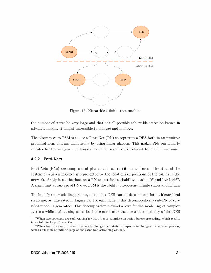
START
END
ENDSTART
Top Tier FSM
Lower Tier FSM
Figure 15: Hierarchical finite state machine
the number of states be very large and that not all possible achievable states be known in
advance, making it almost impossible to analyze and manage.
The alternative to FSM is to use a Petri-Net (PN) to represent a DES both in an intuitive
graphical form and mathematically by using linear algebra. This makes PNs particularly
suitable for the analysis and design of complex systems and relevant to holonic functions.
4.2.2 Petri-Nets
Petri-Nets (PNs) are composed of places, tokens, transitions and arcs. The state of the
system at a given instance is represented by the locations or positions of the tokens in the
network. Analysis can be done on a PN to test for reachability, dead-lock9 and live-lock10.
A significant advantage of PN over FSM is the ability to represent infinite states and holons.
To simplify the modelling process, a complex DES can be decomposed into a hierarchical
structure, as illustrated in Figure 15. For each node in this decomposition a sub-PN or sub-
FSM model is generated. This decomposition method allows for the modelling of complex
systems while maintaining some level of control over the size and complexity of the DES
9When two processes are each waiting for the other to complete an action before proceeding, which resultsin an infinite loop of no action.
10When two or more processes continually change their state in response to changes in the other process,which results in an infinite loop of the same non advancing actions.
DRDC Valcartier TR 2008-015 31

model. The lower tier model responds to the entry conditions of the state and the exit
condition is determined from the actions of the lower tier.
Petri Nets may be used to address the significant issue of coordination, which consists in
resolving conflicts between agents executing their respective tasks. These conflicts can be
resolved with the use of temporary exclusion zones that allow only one agent to access a
particular common resource at a given time. Petri-Nets have been shown to have the ability
to model this type of conflict resolution [36].
An example of this ability is illustrated in Figures 16 to 18. Task Holon (TH1) requests
service from a common Resource Holon (RH) before Task Holon TH2. This forces TH2
to wait until TH1 is finished. In this example, when TH1 reaches place P3 (Figure 16),
transition T3 can fire because it will meet its trigger conditions: a token in both P3 and
P15.
Sub Task A (TH1)
Sub Task D (TH2)
Sub Task B (TH1)
Sub Task E (TH2)
Sub Task C (TH1)
Sub Task F (TH2)
P1 P2 P3 P4 P5 P6 P7
P8 P9 P10 P11 P12 P13 P14
P15
T1 T2 T3 T4 T5 T6
T7 T8 T9 T10 T11 T12
Figure 16: Petri-Net common resource use coordination (Event n)
The output of T3 is to push a token into P4 (Figure 17); this removes the token from P15
and will prevent transitions T3 or T9 to fire until it returns.
Once the objective of the action associated with place P4 is completed, transition T4 fires
and pushes a token into both P5 and P15 (Figure 18). This implies that TH1 is finished
with the common RH and has relinquished control over it, making it available for TH2.
This is a logical exclusive ‘OR’ operation.
In summary, the PN is the preferred method for modelling complex DES because it uses
an efficient notation both graphically and mathematically. It can analyze the network to
verify desired behaviours during the design state, it can be synthesized into a DES, it can be
applied to different levels of control, and it has been used successfully by a large number of
32 DRDC Valcartier TR 2008-015

Sub Task A (TH1)
Sub Task D (TH2)
Sub Task B (TH1)
Sub Task E (TH2)
Sub Task C (TH1)
Sub Task F (TH2)
P1 P2 P3 P4 P5 P6 P7
P8 P9 P10 P11 P12 P13 P14
P15
T1 T2 T3 T4 T5 T6
T7 T8 T9 T10 T11 T12
Figure 17: Petri-Net common resource use coordination (Event n + 1)
Sub Task A (TH1)
Sub Task D (TH2)
Sub Task B (TH1)
Sub Task E (TH2)
Sub Task C (TH1)
Sub Task F (TH2)
P1 P2 P3 P4 P5 P6 P7
P8 P9 P10 P11 P12 P13 P14
P15
T1 T2 T3 T4 T5 T6
T7 T8 T9 T10 T11 T12
Figure 18: Petri-Net common resource use coordination (Event n + 2)
development teams for the control and coordination of autonomous and semi-autonomous
systems.
4.3 Optimization
Another way to look at SM is through optimization. In fact, optimization-based algorithms
are among the techniques that have been most often applied to the SM problem. In this
approach, a performance-based function is optimized through successive choices of action.
Besides the widely used linear programming-based solutions [37, 38], non-linear optimization
techniques have also been used. Such techniques often model the SM problem as a Markov
Decision Process.
DRDC Valcartier TR 2008-015 33

4.4 Markov decision process
Markovian systems are those systems whose transition functions depend only on the imme-
diately preceding state and action, rather than on all the history of the system. Therefore,
the state xk+1 at time instant tk+1 of such systems will depend only on the state xk and
the action input uk, both at time instant tk
xk+1 = f(xk,uk,wk, tk) (2)
where wk is a random variable that reflects the incomplete predictability of the system
state. At each time period, the process is in a given state xk and the decision-maker is
faced with a set of action alternatives. Associated with states and actions is a cost function
g(xk,uk) derived from some metrics. The four components of a Markov decision process
model are:
- a set of states : this is the set of possible states of the systems given the initial state
and the set of all admissible actions;
- a set of actions : that represents the set of all possible alternatives (actions) one can
choose from;
- a transition function : this defines how the future state of the system will evolve from
its current state under the effect of the actions;
- an immediate reward function: this measures the immediate value of each action given
the state.
The solution to a Markov decision process is called a policy that simply specifies the best
action to take for each state.
There are often a number of different alternatives (actions) to choose among when con-
fronted with such an optimization problem. One-step-ahead (or myopic) approaches con-
sider only the immediate effects of the selected actions. Sometimes, actions with poor
immediate effects can have better long-term ramifications. The action that makes the right
tradeoffs between the immediate rewards and the future gains might represent the best
possible solution. Solving such Markov decision processes is the approach that may help in
modelling and reasoning about multi-stage decision problems, and there are a number of
algorithms that allow automating this solution. Among them, the dynamic programming
approach has witnessed much interest from the SM community. Dynamic programming
refers to a collection of algorithms that can be used to compute optimal policies, given a
perfect model of the environment as a Markov decision process. The most widely used
34 DRDC Valcartier TR 2008-015

version of dynamic programming depends on a recursive algorithm that determines the
minimum costs based on the final state and works backwards.
A variation of the Markov model is the Partially Observed Markov Decision Process (POMDP)
in which only a portion of the state is observable and the policy is determined based on
this partial state vector. This approach is more flexible in that policy can be chosen based
on incomplete information about the environment.
Malhotra [39] describes the management process as a general Markov decision process,
which can be solved by dynamic programming. To avoid a possible combinatorial explosion,
the author proposed using reinforcement learning as an approximate approach to dynamic
programming. Washburn et al. [40] also use a dynamic programming-based approach to
predict the effects of future SM policies. Castanon [41] applied dynamic programming to
the scheduling of multi-mode sensors in the problem of classification of multiple unknown
objects. The problem was formulated as POMDP and Lagrange relaxation was used to
uncouple the multi-object problem into many single-object problems. Stochastic dynamic
programming was also used by D’Ambrosio and Fung [42] to tackle sensor management as
a sequential decision problem.
4.5 Decision theory (utility approach)
Action selection in SM can be treated as a decision process. A number of different techniques
may be considered under this guise, providing they have the three following elements:
- a set of possible actions,
- a set of possible outcomes and associated probabilities,
- a metric that relates utility to action-outcome combinations.
Solutions under this paradigm seek to maximize the utility through action selection. The
main difference between this approach and the Markov approach is that the utility function
can be dependent on more than just the previous state-action pairing. Thus the decision
process can be thought of as a strategy to maximize the overall system utility.
The Bayes’ decision rule can be used in this formalism to find optimal actions with respect
to the utility function defined. Other approaches such as decision trees and information
theory can also be employed; however, the main difficulty is in defining the utility function.
For SM, this function must encapsulate all of the various trade-offs and task priorities
that arise in the dynamic sensing environment. For complex networks of sensors this is an
DRDC Valcartier TR 2008-015 35

extremely difficult task unless the problem is subdivided and multiple utility functions are
defined.
Sensing
Probabilistic
Information
Model P(x|zk)
Expected
Outcomes
E{U(x,u1)}
.
.
.
E{U(x,u2)}
Utility
Structure
U(x)
Maximise
Expected
Utility
u*=arg max E(x,u)
Action
u={u1,…..un}
Figure 19: Sensor management based on utility
Figure 1911 shows one example of a control technique incorporating utility metrics. Here
probability information is used to select actions that maximize the expected utility. The
computation of expected utility depends on the nature of the control problem. Deliberative
objectives can be treated with a formulation of utility that measures task completion while
reactive objectives require a formulation where expected utility is calculated for a prede-
termined event horizon. A short event horizon will lead to the selection of actions that
maximize utility in the short-term, ignoring possible long-term solutions with an initial low
utility. A longer event horizon can overcome this but the system will respond slower to
new sensor readings. For SM systems, deliberative goals (i.e., maintaining sensor coverage)
must be balanced with reactive goals (e.g., accurate target tracking) when formulating the
utility metrics.
A decision theoretic approach to cooperative sensor planning between multiple autonomous
vehicles executing a military mission was described by Cook et al. [44]. The objective in
this study was to maximize the expected utility of the information gathered by the sensors
while minimizing one’s exposure to the enemy. The expected utility of detecting an object
is balanced by the utility of maintaining the stealth of the vehicle (which is the negative of
the expected cost of being discovered by the enemy).
11From Grocholsky (2002) [43].
36 DRDC Valcartier TR 2008-015

4.6 Neural networks
The field of Artificial Intelligence (AI) provides a number of promising technologies that may
be adapted for use in SM. Artificial Neural Networks (ANNs) are well suited for learning
functions or mappings with the property of generalization. In the context of the action
selection methods outlined above, NNs could be used to map a metric (utility function,
cost function, control feedback) directly to control actions. For SM applications, the chief
drawback of this approach is that an ANN requires a teacher.
Learning is an iterative process, which in a SM context means that the ANN would have
to monitor a functioning management system until the proper control actions are learned
for every situation. Extrapolation helps reduce the amount of training although there is no
guarantee that the ANN will perform any better than the system it is learning from.
An approach that addresses the training requirement is reinforcement learning. Often
incorporating ANN, reinforcement learning does not require an exact input-output data
but an input-reinforcement pairing. The reinforcement signal rates the choice of action at
each time step and the ANN is updated accordingly. For SM, performance or utility-based
metrics can be used as a reinforcement signal. Reinforcement learning can lead to optimal
solutions with iterative training and can be used alone to improve an already functioning
SM system.
4.6.1 Reinforcement learning
A reinforcement learning technique, known as Temporal Differencing (TD) [45], is closely
related to dynamic programming but does not require a complete description of the environ-
ment. TD is an iterative approach that depends only on local state transition information
yet still recovers globally optimal solutions. The drawback with this approach is that the
controller needs to make a number of practice attempts (learning) before the solution is
found. Typically TD uses an ANN to enhance the learning process. This provides some
generalization so that not every state needs to be visited during training. For SM, this
means that the system would still need to be trained in a great variety of sensing situa-
tions.
A reinforcement learning technique for SM was proposed by Kreucher et al. [46].
4.6.2 Cerebellar model articulation controller
Another technique that has been used in the field of robotic control is the Cerebellar Model
Articulation Controller (CMAC) [47]. The CMAC utilizes coarse coding to learn functions,
DRDC Valcartier TR 2008-015 37
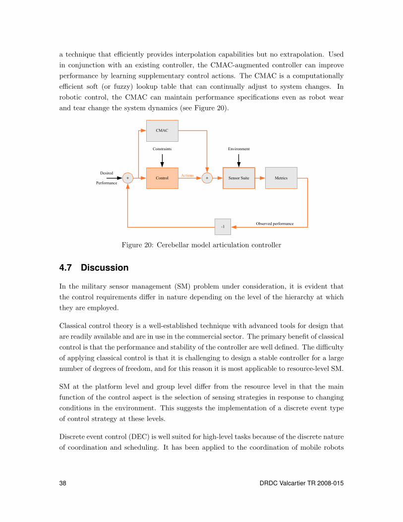
a technique that efficiently provides interpolation capabilities but no extrapolation. Used
in conjunction with an existing controller, the CMAC-augmented controller can improve
performance by learning supplementary control actions. The CMAC is a computationally
efficient soft (or fuzzy) lookup table that can continually adjust to system changes. In
robotic control, the CMAC can maintain performance specifications even as robot wear
and tear change the system dynamics (see Figure 20).
Control Sensor Suite Metrics+
-1
EnvironmentConstraints
Observed performance
Desired
Performance
Actions
CMAC
+
Figure 20: Cerebellar model articulation controller
4.7 Discussion
In the military sensor management (SM) problem under consideration, it is evident that
the control requirements differ in nature depending on the level of the hierarchy at which
they are employed.
Classical control theory is a well-established technique with advanced tools for design that
are readily available and are in use in the commercial sector. The primary benefit of classical
control is that the performance and stability of the controller are well defined. The difficulty
of applying classical control is that it is challenging to design a stable controller for a large
number of degrees of freedom, and for this reason it is most applicable to resource-level SM.
SM at the platform level and group level differ from the resource level in that the main
function of the control aspect is the selection of sensing strategies in response to changing
conditions in the environment. This suggests the implementation of a discrete event type
of control strategy at these levels.
Discrete event control (DEC) is well suited for high-level tasks because of the discrete nature
of coordination and scheduling. It has been applied to the coordination of mobile robots
38 DRDC Valcartier TR 2008-015

in manufacturing, logistics, and other domains. DEC can be designed to react to both
planned and unplanned events and allow for operator intervention to resolve ambiguities if
necessary. It is, however, only limited to the system states that define it, and if a system
enters an unplanned state, then it may not respond favourably. The Petri-Net formulation
of DEC is particularly well suited for the military SM problem as it is formulated in a
hierarchical manner.
DEC produces an action as a result of state transitions. This action must be planned in ad-
vance, which requires a significant amount of foresight from the designer, and consequently,
does not necessarily provide an optimal solution. This may be particularly evident in cases
where resources are insufficient to meet the sensing requirements or when communication
between the controller and the resources are limited. In the first case, optimal utilization
of the sensors aboard a platform may mean addressing both immediate and future threats
while ignoring broader mission objectives. In the second case, optimal control would account
for expected delays in status updates.
A solution to this problem is to implement an optimization or decision theory approach
within the discrete events framework to optimize the actions in response to state transitions.
The optimization approach is either a minimization of cost or the maximization of a utility
function. Either variant generates a decision as to what action to take next. Optimization
approaches are less well defined than the classical control approach, and therefore, have
fewer design tools available. The optimization approach is well suited to SM because of its
ability to accommodate both discrete and continuous time equally well.
Pure learning approaches, such as neural networks (NN) and reinforcement learning, are
not suitable for SM. In learning systems, it is very difficult to guarantee any level of desired
performance until exhaustive training is completed. The performance of the system would
be only as good as the training it received. In the real world of SM, if a learning system
encounters situations for which it wasn’t trained for, its level of performance may drop
significantly and it might behave in unexpected ways. Learning-based control works best
with repeatable situations with some limited degree of variability. However, when a learning
system is coupled with another type of controller with an established performance, the
learning element will improve the performance over time.
DRDC Valcartier TR 2008-015 39

This page intentionally left blank.
40 DRDC Valcartier TR 2008-015

5 Holonic control structure
The discussion of the advantages and the shortcomings of different system architectures
in Chapter 3 showed the potential that the holonic approach presents for military control
problems, such as sensor management. This approach will maintain a command and control
structure similar to that used by the military today. The primary benefit of holonic control
is its ability to form a localized structure, or holarchy, to address needs as they arise.
The holonic control approach allows for a hybrid hierarchy that will retain the benefits of
stability of a true hierarchy while providing the flexibility and robustness of a distributed
system.
This chapter provides an overview of holonic systems. It presents the general concept of
holons and the characteristics of holonic organizations. Related work on holonic systems,
in particular in the manufacturing domain, is presented. Next, the relationship between
holonic systems and Multi-Agent Systems (MAS) and the use of agent technology for im-
plementation of a holonic system are discussed.
5.1 Holons
The term “holon” was coined by Arthur Koestler to explain complex biological and social
systems [48]. He made two key observations in this area [19]:
1. These systems evolve and grow to satisfy increasingly complex and changing needs
by creating stable intermediate forms that are self-reliant and more capable than the
initial systems.
2. In living and organizational systems, it is generally difficult to distinguish between
wholes and parts. Almost every distinguishable element is simultaneously a whole
(an essentially autonomous body) and a part (an integrated section of a larger, more
capable body).
Koestler used the Janus effect as a metaphor for this dichotomy of wholeness and partness
observed in many such systems: like the Roman god Janus, members of a hierarchy have two
faces looking in opposite directions [49]. These members can be thought of as self-contained
wholes looking towards the subordinate level and dependent parts looking upward. To refer
to this concept, Koestler suggested a new term: holon, from the Greek holos meaning whole
and the suffix -on implying particle as in proton or neutron.
The holonic structure is intended to address the difficulty of coordination in decentralized
systems. A “holonically” organized system consists of autonomous, self-reliant units, or
DRDC Valcartier TR 2008-015 41
holons [50], which co-operate to achieve the overall system objectives. Holons have a certain
degree of autonomy that allows them to make decisions of limited scope. The decisions that
a holon can make are limited to accepting the request being made and executing the request
by utilizing available resources. The process used to arrive at a decision is only as complex
as necessary for that class of holons and its level within the holarchy. For simple systems,
the decision process for a given holon is a set of fixed rules that govern its behaviour.
The flexibility displayed by holonic systems is the result of the combined behaviour of the
holarchy and not the actions of an individual holon.
Some key properties of a holonic system developed in Koestler’s model are [19]:
Autonomy – the capability of a holon to create and control the execution of its own
plans and/or strategies (and to maintain its own functions). Each holon has local
recognition, decision-making, planning, and action taking capabilities, enabling it to
behave reactively and pro-actively in a dynamic environment.
Co-operation – the process whereby a set of holons develop mutually acceptable
plans and execute them. Coordination, negotiation, bargaining, and other co-operation
techniques allow holons to flexibly interact with other holons in an abstract form. Be-
cause of the dynamic nature of the holarchies, each holon must employ generalized
interaction patterns and manage dynamic acquaintances.
Self-organization – the ability of holons to collect and arrange themselves in or-
der to achieve an overall system goal. Holonic systems immediately re-negotiate the
organization of the system whenever environmental conditions change.
Reconfigurability – the ability of the function of a holon to be simply altered in
a timely and effective manner. Because of the modular approach, holons can be
reconfigured locally once the inherent flexibility of the holons has reached its limit.
The notion of functional decomposition is another important ingredient of the holonic con-
cept. It can be explained by Simon’s observation when he says that “complex systems
evolve from simple systems much more rapidly if there are stable intermediate forms than if
there are not” [51]. In other words, the complexity of dynamic systems can be dealt with by
decomposing the systems into smaller parts. A consequence of this is the idea that holons
can contain other holons (i.e., they are recursive). Also, problem solving is achieved by
holarchies, or groups of autonomous and co-operative basic holons and/or recursive holons
that are themselves holarchies.
42 DRDC Valcartier TR 2008-015
5.2 Holonic systems
It was in the manufacturing domain where a marriage between Koestler’s general philos-
ophy, inspired by living organisms and social organizations, and emerging software ap-
proaches (distributed artificial intelligence) began. The Holonic Manufacturing Systems
(HMS) consortium started as a two-year feasibility study in February 1992 [31] with the
goal of “attain[ing] in manufacturing the benefits that holonic organization provides to
living organisms and societies, e.g., stability in the face of disturbances, adaptability and
flexibility in the face of change, and efficient use of available resources”.
Given these basic building blocks, the HMS community next looked at how holons could
be implemented to solve basic manufacturing problems. As noted previously, Van Brussel
et al. [52] proposed a reference architecture, called the Product-Resource-Order-Staff Ar-
chitecture (PROSA), to address this issue; that consists of four fundamental holon types:
Product Holon – The product holon contains process and product knowledge in
order to ensure that products are made correctly and in sufficient quantity. As a
result, this holon is responsible for the functionalities that are traditionally covered
by product design, process planning, and quality assurance.
Resource Holon – The resource holon is an abstraction of the production processes
(factory, shop, machine, conveyor, robot, etc.) in a manufacturing system. It provides
production capacity and functionality to other holons.
Order Holon– The order holon manages the set of physical products being produced.
As a result, it is concerned with logistical information and may represent customer
orders, make-to-stock orders, etc.
Staff Holon – The staff holon is an optional element of the PROSA architecture
that is used to assist the basic (Resource, Product, Order) holons for performing their
work. For example, the staff holon may play the role of a mediator as in Maturana
and Norrie’s Metamorph architecture [53].
The basic building blocks of the PROSA architecture are illustrated in Figure 21 (from [52]),
where each of the three main types of holons are intended to be responsible for manufac-
turing control. The staff holon can be combined with these basic holons to provide expert
knowledge for longer-term, strategic decision making, fault-diagnosis, maintenance, etc.,
and to facilitate the incorporation of legacy systems.
Another important property of holons that is not illustrated in Figure 21 is that they can
contain other holons (since they are recursive). Problem solving is achieved by holarchies,
DRDC Valcartier TR 2008-015 43

Figure 21: PROSA architecture of holonic manufacturing system
or groups of autonomous and co-operative basic or recursive holons that are themselves
holarchies. In order to achieve this form of co-operation, the notion of a co-operation domain
was introduced in holonic systems, which as Fletcher et al. note in [54], “is considered a
logical space in which holons communicate and operate, that provides the context where
holons may locate, contact and interact with each other”. Within this framework, two types
of co-operation occur among holons [54]:
Simple Co-operation – a holon is committed to answer queries from another holon,
even if the response is non-co-operative.
Complex Co-operation – holons achieve a joint goal (e.g., agree upon a mutual
plan for solving a distributed problem).
This second form of co-operation is based on the concept of cooperation domains, and
requires an integration of the physical device level with the higher reasoning/deliberative
level of the system.
5.3 Holons and agents
The common thread that runs throughout the work on holonic systems is the close link
between distributed artificial intelligence, multi-agent systems (MAS), and holonic sys-
tems. Given the close link between the latter systems, various co-operation, communica-
tion, and organizational techniques from the MAS literature [55] can be used to implement
autonomous, co-operative, and recursive agents (i.e., “holons”). For example, the notion
of holarchies can be implemented using various federated architecture approaches such as
facilitators, brokers, or mediators (e.g., see [53] and § 3.4). The resulting software agent
may be considered a holon, or it may be considered the information processing part of a
holon.
44 DRDC Valcartier TR 2008-015
The implementation of the holon depends on the role it plays and on its position within the
system hierarchy. In other words, it is the stance that is taken towards the control problem
that will influence whether agents, holons, or function blocks are to be used.
5.3.1 Multi-agent systems
Multi-agent systems (MAS) can be thought of as a “general software technology that was
motivated by fundamental research questions” [50], such as how groups of software agents
work together to solve a common problem [56]. Agents are defined as “active, persistent
(software) components that perceive, reason, act and communicate” [57]. This definition
follows from the notion of a software object where the focus is on data abstraction, encap-
sulation, modularity, and inheritance [58].
A major advantage of agent-based software over conventional software is this autonomous
nature of individual agents. As noted by Parunak, agents “decide locally not only how to
act12, and what actions to take13, but also when to initiate their own activity” [59]. This,
in combination with the co-operative nature of agents in MAS, is particularly well suited
for distributed intelligent control problems. In particular, autonomous agents or MAS are
attractive software engineering tools for the development of systems in which “data, control,
expertise, or resources are distributed; agents provide a natural metaphor for delivering
system functionality; or a number of legacy systems must be made to interwork” [60].
5.3.2 Agent architecture
In this section, we briefly review the different internal architectures that are used to de-
fine agents. These are categorized based on: reasoning mode and internal organization.
A detailed description of each of these architectures presented here can be found in [55]
or [61], however for the purpose of this review, we will highlight the main points for each
architecture.
5.3.2.1 Reasoning mode
Agent architectures that are categorized by the reasoning mode of agents fall into three
main types: deliberative, reactive, and hybrid.
Deliberative – Deliberative agents14 have a domain knowledge and the planning
capability to undertake a sequence of actions with the intent of moving towards a
12As subroutines do.13As objects do.14Also known as cognitive, intentional, or goal-directed agents.
DRDC Valcartier TR 2008-015 45

goal [61]. One of the most well-known deliberative agent architectures is the Belief-
Desire-Intention (BDI) architecture that describes the internal state of an agent by
means of a set of mental categories; to control its actions, the agent rationally selects
its course of actions based on its representations [62].
Reactive – At the other end of the behavioural spectrum are reactive agents15, where
agents do not have a model of the world but they respond in an event-condition-action
mode [63]. This architecture tends to be used in low-level control, robotics, and
physical sensor applications because of its timeliness and emergent behaviour. One
of the earliest reactive agent architectures is the subsumption architecture proposed
by Brooks [63] where multiple behaviours associated with a specific level of activities
compete to win control over activities.
Hybrid – Hybrid agents fall somewhere in the middle of the spectrum delimited
by the deliberative agent and the reactive agent. The motivation for this type of
agents came about because purely reactive architectures cannot implement general
goal-directed behaviour, while purely deliberative architectures are not effective in
large, complex systems due to their potentially huge symbolic knowledge representa-
tions. An example of a hybrid architecture can be found in Franklin’s “general agent
architecture” [64].
5.3.2.2 Internal organization
As noted previously, agents can also be described by their internal organization. In particu-
lar, five main categories16 of agent architectures are typically used: modular, subsumption,
blackboard, production system and layered.
Modular – The modular agent architecture is typically organized as an assembly
of agent modules that realize a particular agent function, e.g., planning, execution,
perception, etc. These architectures tend to be associated with more complex agents,
and in particular, deliberative agents.
Subsumption – A subsumption architecture is a way of decomposing complicated
intelligent behaviour into many “simple” behaviour modules, which are in turn orga-
nized into layers. Each layer implements a particular goal of the agent, and higher
layers are increasingly more abstract. Each layer’s goal subsumes those of the under-
lying layers. This category of architecture has been the basis for the earliest reactive
agent architectures.
15Also known as behaviour-based agents or simulated agent architectures.16Note that these categories are non-exclusive.
46 DRDC Valcartier TR 2008-015
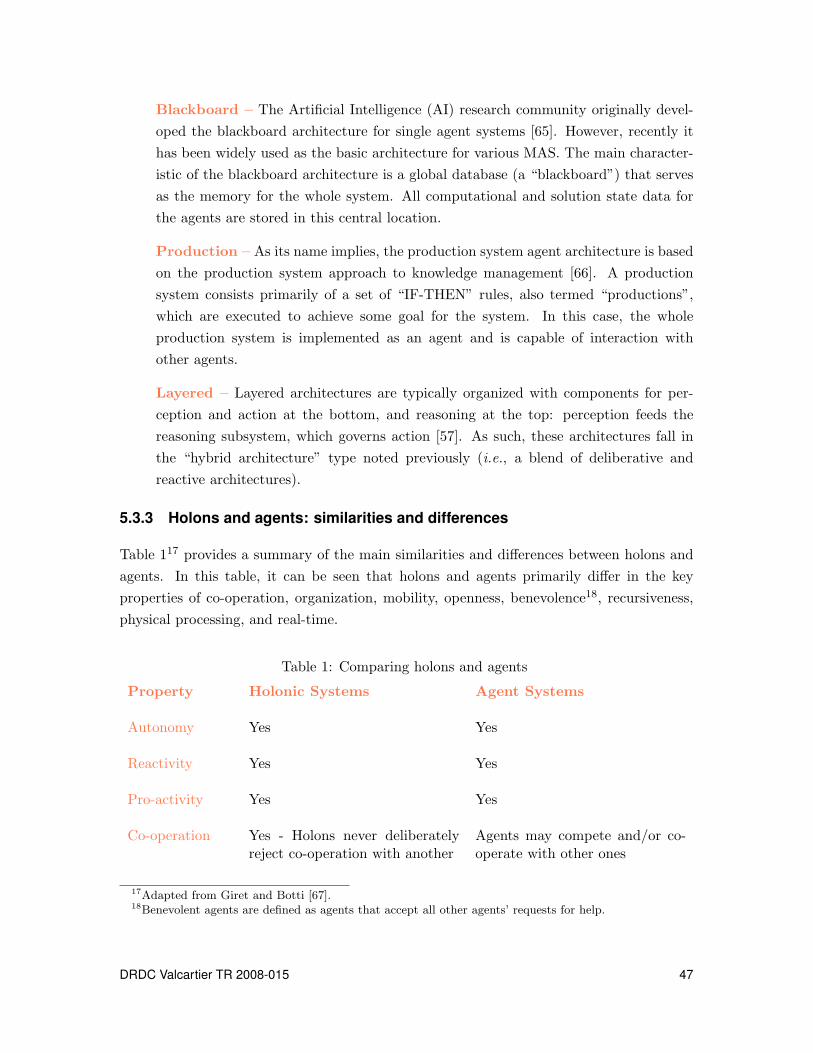
Blackboard – The Artificial Intelligence (AI) research community originally devel-
oped the blackboard architecture for single agent systems [65]. However, recently it
has been widely used as the basic architecture for various MAS. The main character-
istic of the blackboard architecture is a global database (a “blackboard”) that serves
as the memory for the whole system. All computational and solution state data for
the agents are stored in this central location.
Production – As its name implies, the production system agent architecture is based
on the production system approach to knowledge management [66]. A production
system consists primarily of a set of “IF-THEN” rules, also termed “productions”,
which are executed to achieve some goal for the system. In this case, the whole
production system is implemented as an agent and is capable of interaction with
other agents.
Layered – Layered architectures are typically organized with components for per-
ception and action at the bottom, and reasoning at the top: perception feeds the
reasoning subsystem, which governs action [57]. As such, these architectures fall in
the “hybrid architecture” type noted previously (i.e., a blend of deliberative and
reactive architectures).
5.3.3 Holons and agents: similarities and differences
Table 117 provides a summary of the main similarities and differences between holons and
agents. In this table, it can be seen that holons and agents primarily differ in the key
properties of co-operation, organization, mobility, openness, benevolence18, recursiveness,
physical processing, and real-time.
Table 1: Comparing holons and agents
Property Holonic Systems Agent Systems
Autonomy Yes Yes
Reactivity Yes Yes
Pro-activity Yes Yes
Co-operation Yes - Holons never deliberatelyreject co-operation with another
Agents may compete and/or co-operate with other ones
17Adapted from Giret and Botti [67].18Benevolent agents are defined as agents that accept all other agents’ requests for help.
DRDC Valcartier TR 2008-015 47
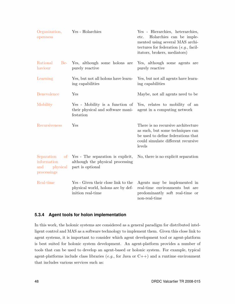
Organization,openness
Yes - Holarchies Yes - Hierarchies, heterarchies,etc. Holarchies can be imple-mented using several MAS archi-tectures for federation (e.g., facil-itators, brokers, mediators)
Rational Be-haviour
Yes, although some holons arepurely reactive
Yes, although some agents arepurely reactive
Learning Yes, but not all holons have learn-ing capabilities
Yes, but not all agents have learn-ing capabilities
Benevolence Yes Maybe, not all agents need to be
Mobility Yes - Mobility is a function oftheir physical and software mani-festation
Yes, relates to mobility of anagent in a computing network
Recursiveness Yes There is no recursive architectureas such, but some techniques canbe used to define federations thatcould simulate different recursivelevels
Separation ofinformationand physicalprocessings
Yes - The separation is explicit,although the physical processingpart is optional
No, there is no explicit separation
Real-time Yes - Given their close link to thephysical world, holons are by def-inition real-time
Agents may be implemented inreal-time environments but arepredominantly soft real-time ornon-real-time
5.3.4 Agent tools for holon implementation
In this work, the holonic systems are considered as a general paradigm for distributed intel-
ligent control and MAS as a software technology to implement them. Given this close link to
agent systems, it is important to consider which agent development tool or agent-platform
is best suited for holonic system development. An agent-platform provides a number of
tools that can be used to develop an agent-based or holonic system. For example, typical
agent-platforms include class libraries (e.g., for Java or C++) and a runtime environment
that includes various services such as:
48 DRDC Valcartier TR 2008-015

- messaging services,
- agent registration and deregistration services (i.e., “white page” services),
- agent look-up services (i.e., “yellow page” services),
- diagnostics (e.g., graphical views of messaging activity).
Since holonic systems are typically implemented at the device level (i.e., where there is
typically connection to physical equipment), it is important for the agent-platform used in
support to this approach to be fast, to have a relatively small memory footprint, and to
be reliable. Given the work that has been done by the Foundation for Intelligent Physical
Agents (FIPA) on Agent Communication Languages [68], it is also desirable that the agent-
platform supports the FIPA inter-agent communication standards.
Vrba [69] performed a comparison of seven open-source19 and five commercial20 Java-based
agent-platforms to determine their suitability for holonic systems implementation. Each
platform was compared along the lines of FIPA compatibility, memory footprint, security,
and message speed. The results of this study showed that the JADE platform was the most
suitable open-source agent development tool. In comparison with its closest competitor,
FIPA-OS, it offers approximately twice the speed in message sending, is more stable in
terms of number of agents deployed, and provides better memory utilization [69]. Among
the commercial platforms, JACK compares favorably to JADE and is faster in some cases.
JACK’s main drawback is that it relies on an unsupported plug-in to achieve full FIPA
compliance. Furthermore, JACK agents are implemented using the BDI model21.
To implement agents or holons in software, it is not necessary to use these pre-packaged tools
if FIPA compliance is not required. FIPA compliance is of benefit if the implemented agents
are to interact with other real-world systems that make use of FIPA to define inter-agent
communications for the exchange of information and negotiations.
Holons can be created using any high-level object-oriented programming language such
as C++, Java, Python or MATLAB. Typically, Java is the favoured tool because of its
universal appeal and its network-friendly architecture. Language tools like Python and
MATLAB are both object-oriented scripting tools that allow for rapid development cycles
of new concepts. MATLAB does have one distinct advantage over the other tools: it has an
integrated simulation environment, Simulink, which allow agents/holons to interact natively
with a virtual world.19Java Agent DEvelopment Framework (JADE), FIPA-OS, ZEUS, Java Agent Services API (JAS), Multi-
Agent Development Kit (MadKit), Comtec Agent Platform, and Aglets.20JACK, Grasshopper, Agent Development Kit (ADK), AgentBuilder, and Bee-gent.21This may or may not be considered an advantage depending on the application.
DRDC Valcartier TR 2008-015 49

To conclude, we can say, that for system implementations with hard real-time requirements,
FIPA-compatible tools such as Jack or FIPA-OS are advocated. If “real-timeliness” is not
an issue, any high-level programming tool can be used.
50 DRDC Valcartier TR 2008-015

6 Holonic sensor management
As discussed in the previous section, the manufacturing sector has been an early adopter
of the holonic control methodology and has invested heavily in research and development
through the Holonic Manufacturing System (HMS) initiative. HMS focuses on the coordi-
nation of resources and tasks in the manufacturing of goods.
This is not too dissimilar to the objective of controlling and coordinating sensors to provide
the right people with the necessary information at the right time. If one considers infor-
mation as the product, military assets with sensing capabilities as the manufacturing tools,
and raw sensor data as the raw materials, then the analogy is a good but not perfect one. In
manufacturing, raw materials are transformed into finished products for the market place.
In military surveillance application, raw sensor data are transformed into useful information
for situation awareness.
Some of the potential drawbacks with applying holonic control to military sensor manage-
ment (SM) are:
- military operations may be larger in the spatial scale,
- disruptions in the process are the norm rather than the exception,
- there may be deliberate attempts to sabotage a process,
- the sensor integration is more complex and crucial to human safety,
- human influence on the process is generally deemed necessary and is more frequent.
However, the holonic control approach allows for a hybrid hierarchy that will retain the
benefits of stability of a true hierarchy while providing the flexibility and robustness of a
distributed system. By choosing this approach, success is more likely because a hierarchical
structure can be imposed to limit chaotic behaviour, thereby preventing instability in the
solution.
The concept of applying holonic control methodology to the task of military SM is illustrated
in Figure 22 and discussed in the remaining of this chapter.
6.1 Sensor management holarchy
The proposed holarchy structure for SM is decomposed into three main levels: sensor, plat-
form, and group. The levels are related to each other in a recursive manner typical of
DRDC Valcartier TR 2008-015 51
holonic systems. The sensors represent the lowest level of the holarchy. Each platform con-
trols and coordinates the sensors that are located aboard it, but do not control the sensors
aboard other platforms. Likewise, the group level manager coordinates sensing activities
between platforms but does not directly control the sensors aboard those platforms.
The hierarchical nature of the SM problem leads to a natural breakdown in the control
structure. The nature of the control is dependent on the level at which it is implemented.
At the group level, for example, the control output from SM is actually a set of broad
sensing objectives that are issued to the platforms. In surveillance, for instance, control
outputs may specify which targets each platform should track, or which areas to observe
for search purposes.
At the platform level, these control inputs (from a group level) are interpreted and planned
for, resulting in the issuing of more specific commands to the on-board sensors. In surveil-
lance, these commands may specify which sensor should search which areas, or which sensor
should track which target.
Figure 23 represents a single SM system that may be located at any level in the control
holarchy. It shows the elements of a basic holonic structure, from the Service Interface and
Command Holon (SICH) between the SM system and Task Holons (TH) as members of a
Resource Holon (RH), then to subsystems with simplest RH.
The next section describes the nature and specific role of each type of holons within the
holarchy.
6.2 Control and coordination techniques for holarchies
In multi-level systems, such as holonic systems, control at a given level takes place in a
continuous space, while coordination is performed in a discrete space. Furthermore, control
can be temporally continuous or discrete depending on the level in the holarchy. The
nature and complexity of such systems make it difficult to approach them using a single
tool. An interesting approach consists therefore in combining the holonic system paradigm
with hybrid control schemes, i.e., designs that make use of both discrete and continuous
controllers, at different time scales, both synchronously and asynchronously. Several reasons
justify the use of such a hybrid representation. The most straightforward is the reduction of
the complexity of the model through the use of a hierarchical/holonic representation with
different levels of abstraction. In such a hierarchy or holarchy, higher levels require less
detailed models than the lower levels.
Approaches to the control and coordination problem can be derived from a number of
52 DRDC Valcartier TR 2008-015

Complex Platform Resource Holon
Task Goup HolonGroup of Simple Platforms Holon
Simple Platform Holon
Sensing
Holon
Service
Interface &
Command
Holon
Complex Platform Resource Holon
Sensing
Holon
Helm &
Engineering
Holon
Weapons
Holon
Service
Interface &
Command
Holon
Service Interface &
Command Holon
Simple Resource
Holon
Sensing
Holon
Service
Interface
Simple Resource
Holon
Sensing
Holon
Service
Interface
Service
Interface &
Command
Holon
Task Holon
(Search for New Objects)
Task Holon
(Track Object Y)
Task Holon
(Engage Target X)
Sensing Group Resource Holon
Simple Resource Holon
Helm & Engineering Holon
Sensing
Holon
Service
Interface &
Command
Holon
Steering
Holon
Engine
Room
Holon
Service
Interface &
Command
Holon
Complex Sensing Resource Holon
Sensing 1
Holon
Sensing 3
Holon
Sensing 2
Holon
Service
Interface &
Command
Holon
Weapons Resource Holon
Weapons 1
Holon
Weapons 2
Holon
Service
Interface &
Command
Holon
Service Interface &
Command Holon
Simple Resource
Holon
Sensing
Holon
Service
Interface
Holon
Simple Resource
Holon
Sensing
Holon
Service
Interface
Holon
Service
Interface &
Command
Holon
Task Holon
(Search for new Objects)
Task Holon
(Engage Target X)
Task Holon
(Track Object Y)
Task Holon
(Survey the VOI)
Command Center
Operational Request
(Survey the VOI)
Figure 22: Example of holonic control and coordination of sensing resources(orange lines represent control flow, black dotted lines represent data flow)
DRDC Valcartier TR 2008-015 53

Figure 23: Recursive sensor management in holonic structure
sources such as Control Theory and AI. A number of approaches were discussed in Chap-
ter 4. For the continuous space problems, approaches such as Control Theory and Optimiza-
tion could be used. For the discrete coordination problems, approaches such as Petri-Nets,
Decision Theory, and Markov Decision Process would be more appropriate. In fact, co-
ordination problem can be tackled from different perspectives and at different levels of
abstraction when using holonic systems.
6.3 Elements of the holarchy
The following paragraphs briefly describe the main elements (holons) of the holonic sensor
management system concept, as shown in Figure 22. Other elements that interact with the
sensing elements have been included for context illustration purposes.
6.3.1 Command centre
The command centre is the entity that requires a specific piece of information from the
entire surveillance network. The command centre makes a request to the force/group-level
SICH, which is described in the next subsection. This interface holon acts as a single point
of contact to the network of the SM system. When the information is generated, this holon
delivers the requested material to the command centre, as it requests the type of informa-
tion it needs at that time and assigns a priority to it. The priority defines the regional
significance and the need significance. For example, a request with a local significance for
self-preservation requires real-time response that would take priority over a request with
54 DRDC Valcartier TR 2008-015

global significance for monitoring a large region. Both are viewed as high priority by their
respective command-level; however, the self-preservation goal of the resources will take pri-
ority because if it does not, the resource will no longer be able to fulfill the global request.
6.3.2 Service interface and command holon
A Service Interface and Command Holon (SICH) responds to requesting holons to define
the constraints of their request and then spawns a task holon (TH). The SICH then releases
this TH into the network. When the TH returns, the resulting information is presented
to the requesting holon and the corresponding TH that gathered the information is then
killed off. A fixed communication hierarchy is defined with respect to the SICHs. SICHs
require constant two-way communications with each other within the holarchy in order to
keep track of resource availability and transfer information up the chain of command. This
communications hierarchy is defined according to functional significance, i.e. group-level
SICH connects to platform holons while each platform SICH connects to its own internal
Resource Holon (RH).
From a control point of view, the SICH is responsible for interpreting high-level sensing
objectives and generating sensing tasks that address them. The SICH is required to gen-
erate task plans in response to changing conditions in the environment. For instance, at
the platform level, the SICH would be responsible both for utilizing the information gath-
ered from sensor data and the resource status information to derive sensor allocations and
performance specifications, and then rating the criticality of the task. As events in the
environment unfurl, these task plans would need to be updated, created or destroyed.
6.3.3 Task holon
A Task Holon (TH) is a holon that once created, autonomously travels through a network
and makes use of the resources that are either allocated to it or that it negotiates for itself.
This holon differs from other holons in the network as it only exists for the duration of the
request and is in effect a roaming client in a network of services. The main purpose of this
class of holons is to utilize RH to fulfill its mandate. This is an ongoing process whereby
resource holons are recruited or dismissed on an as-needed basis; thus forming a temporary
hierarchy. THs operate in either event-driven or continuous time modes depending on the
nature of their task. A TH establishes communication links with the resources directly
below it and stays in communication with the SICH above it. This provides an alternate
route for task-specific information to flow upwards in the hierarchy.
DRDC Valcartier TR 2008-015 55
6.3.4 Resource holon
Resource Holons (RH) are the systems and devices that are coordinated at each level in
the holarchy. At the group-level, an RH corresponds to an individual platform, while
within each platform, an RH corresponds to an individual sensor. The holon hierarchy
(holarchy) is recursive by definition, which means that the structures are similar at any
level of abstraction. A complex resource, such as a frigate, would be subdivided into holons
representing functional systems onboard that must function together but are well defined in
their own right. Simple resources, such as a UAV, are already at their most basic level and
would not benefit from further subdivision. RHs are tasked by the SICHs through which
THs make their requests for access to resources. Each RH provides to the THs information
about its current status and capabilities through the SICH.
Returning to the manufacturing example introduced in the previous section (§ 5.2), the
(sensor) RHs can be thought of as specialized PROSA resource holons, and a TH can
be thought of as a specialized PROSA order holon. In the case of PROSA, order holons
manage a set of physical products being produced by the RHs; in the case of an SM system,
THs manage a set of sensor data produced by the RHs. Similarly, the customer order
can be thought of as the commanding officer’s request for tracking data. Of course, the
SM example may also be extended with a higher-level staff holon that is responsible for
Command and Control functionality in the broader sense (e.g., response planning, threat
evaluation, etc.).
6.4 Task organization within the holarchy
The holonic SM system consists of a loosely defined architecture, the dimensions of which
are to be determined relatively to the spatial and temporal scales of the problems to be
addressed. The system is basically a distributed one, but a hierarchy is imposed for logical
division of efforts and resources. Problem decomposition is performed according to the
level of abstraction required by each task. For example, at the highest levels, the holons
are concerned with “big picture” problems. At the lowest levels, they are concerned with
more detailed (and arguably simpler) problems.
At the highest level is the command centre, staffed with high-level military operational
planners and senior commanders. The command centre interacts with any number of group-
level holons. A group-level holon is a collection of platform resources, such as frigates, UAVs,
airplanes, and ground-based assets. The SICH is responsible for spawning THs, responding
to commands from a higher level in the holarchy, and maintaining a status of the RHs
directly below it, through interaction with its THs.
56 DRDC Valcartier TR 2008-015
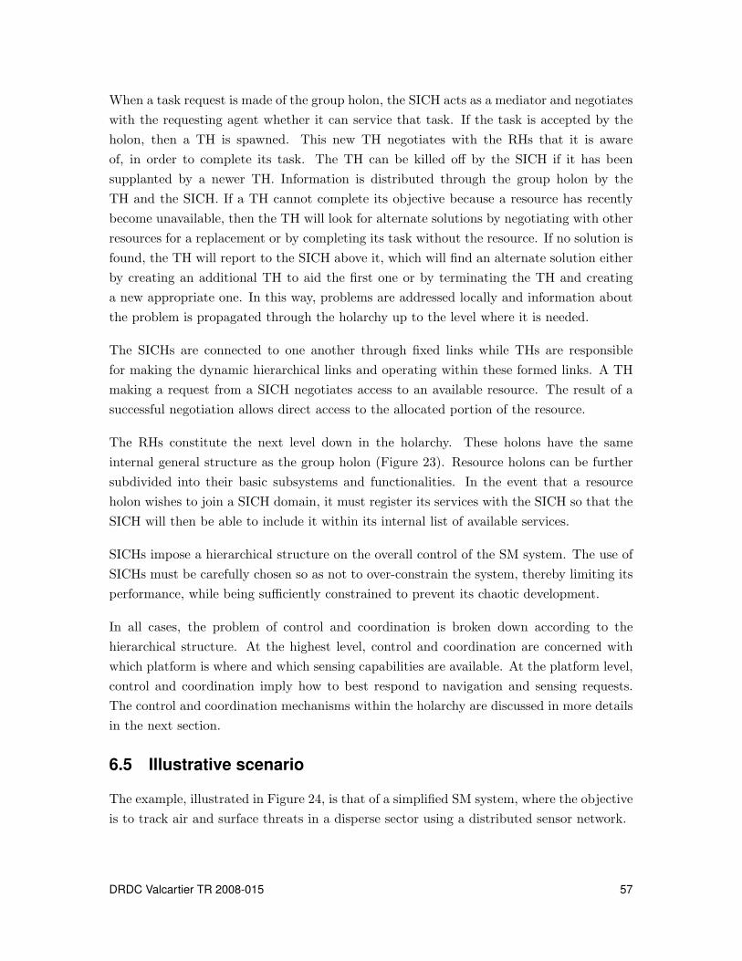
When a task request is made of the group holon, the SICH acts as a mediator and negotiates
with the requesting agent whether it can service that task. If the task is accepted by the
holon, then a TH is spawned. This new TH negotiates with the RHs that it is aware
of, in order to complete its task. The TH can be killed off by the SICH if it has been
supplanted by a newer TH. Information is distributed through the group holon by the
TH and the SICH. If a TH cannot complete its objective because a resource has recently
become unavailable, then the TH will look for alternate solutions by negotiating with other
resources for a replacement or by completing its task without the resource. If no solution is
found, the TH will report to the SICH above it, which will find an alternate solution either
by creating an additional TH to aid the first one or by terminating the TH and creating
a new appropriate one. In this way, problems are addressed locally and information about
the problem is propagated through the holarchy up to the level where it is needed.
The SICHs are connected to one another through fixed links while THs are responsible
for making the dynamic hierarchical links and operating within these formed links. A TH
making a request from a SICH negotiates access to an available resource. The result of a
successful negotiation allows direct access to the allocated portion of the resource.
The RHs constitute the next level down in the holarchy. These holons have the same
internal general structure as the group holon (Figure 23). Resource holons can be further
subdivided into their basic subsystems and functionalities. In the event that a resource
holon wishes to join a SICH domain, it must register its services with the SICH so that the
SICH will then be able to include it within its internal list of available services.
SICHs impose a hierarchical structure on the overall control of the SM system. The use of
SICHs must be carefully chosen so as not to over-constrain the system, thereby limiting its
performance, while being sufficiently constrained to prevent its chaotic development.
In all cases, the problem of control and coordination is broken down according to the
hierarchical structure. At the highest level, control and coordination are concerned with
which platform is where and which sensing capabilities are available. At the platform level,
control and coordination imply how to best respond to navigation and sensing requests.
The control and coordination mechanisms within the holarchy are discussed in more details
in the next section.
6.5 Illustrative scenario
The example, illustrated in Figure 24, is that of a simplified SM system, where the objective
is to track air and surface threats in a disperse sector using a distributed sensor network.
DRDC Valcartier TR 2008-015 57

TH
RH
RH
RHRH
High Interest Target
(Air or Surface Threat)
RH
Figure 24: Simple example of self-organization of resources
Initially, the control system only consists of a pool of unorganized resource (sensor) holons
(RHs). When an air or surface threat occurs, a TH is created, which begins to negotiate
with RHs regarding the provision of certain defensive battle management functions (e.g.,
target detection, target identification/classification, engagement control, etc.). During the
negotiation process, the TH specifies certain properties required for sensor management,
e.g., high target resolution, low communication, and data processing latency. Once the
negotiation is completed, the RHs form the agreed SM system (i.e., a sensor holarchy) and
the TH initiates the tracking process.
As the RHs track the threat, the TH bargains for sensors to obtain the required data (i.e.,
it is assumed that RHs may be tracking more than one target at any given time). Moreover,
the TH may recruit new RHs and/or dismiss unnecessary RHs from the sensor suite as the
threat moves through the sector.
In the case of a disturbance (e.g., a sensor is destroyed), the affected RH is removed from
the sensor holarchy, i.e., a cluster of holons. The remaining RHs then reorganize themselves
to account for the capacity loss. Once the target has passed through the sector or has been
destroyed, the TH is removed and the sensor holarchy dissolves into the RHs, which then
try to participate in new holarchies.
This, of course, is a very simple example that does not capture the complexity of a real
Command and Control (C2) System; rather, it is intended to illustrate the basic holonic
properties discussed previously.
58 DRDC Valcartier TR 2008-015

6.6 Control and coordination within the holarchy
Figure 25 illustrates the functions of control and coordination within the proposed holarchy.
In this figure, control and coordination are broken down into two general functional compo-
nents: task planning and task allocation/scheduling, designed to highlight differing aspects
of the sensor management (SM) problem. At any given level in the command hierarchy,
SM is responsible for translating (relatively) abstract sensing objectives into sensing tasks,
which are then allocated to the sensing resources.
Task Planning
Module
Task Allocation
and Scheduling
Module (ASM)
Sensing ResourcesFusion
Task Request
Task Accept/
Reject
Negotiations
Sensor Management
Task
Accept/
Reject
Status
Task Request
Task
Accept/Reject
Status
TaskRequest
Refined
Information
Figure 25: Control and coordination functions
In the functional breakdown depicted in Figure 25, the task allocation and scheduling
problem is separated from the task planning problem. The task planning module utilizes
the analyzed (fused) data gathered by the sensing resources to produce task requests, which
are passed to the task allocation and scheduling module (ASM). Task requests must include
a measure of task priority as well as performance objectives. The task ASM uses these
requests to select the appropriate resources and control parameters (i.e., scheduling, mode,
etc.) to meet the performance objectives and balance the task priorities.
Both task planning and task allocation aspects can be observed in the holonic structure of
Figure 22. THs take on the role of task ASM, while the SICH acts as the task planner and
handles negotiations with higher-level controllers and subordinate resources. It is worth
noting that task planning does not need to be treated separately from task allocation as
described here. In Chapter 4, control techniques are examined, suggesting that these two
DRDC Valcartier TR 2008-015 59
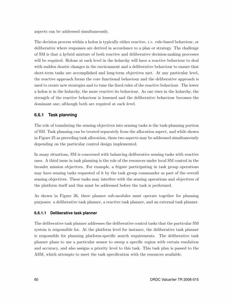
aspects can be addressed simultaneously.
The decision process within a holon is typically either reactive, i.e. rule-based behaviour, or
deliberative where responses are derived in accordance to a plan or strategy. The challenge
of SM is that a hybrid mixture of both reactive and deliberative decision-making processes
will be required. Holons at each level in the holarchy will have a reactive behaviour to deal
with sudden drastic changes in the environment and a deliberative behaviour to ensure that
short-term tasks are accomplished and long-term objectives met. At any particular level,
the reactive approach forms the core functional behaviour and the deliberative approach is
used to create new strategies and to tune the fixed rules of the reactive behaviour. The lower
a holon is in the holarchy, the more reactive its behaviour. As one rises in the holarchy, the
strength of the reactive behaviour is lessened and the deliberative behaviour becomes the
dominant one; although both are required at each level.
6.6.1 Task planning
The role of translating the sensing objectives into sensing tasks is the task-planning portion
of SM. Task planning can be treated separately from the allocation aspect, and while shown
in Figure 25 as preceding task allocation, these two aspects may be addressed simultaneously
depending on the particular control design implemented.
In many situations, SM is concerned with balancing deliberative sensing tasks with reactive
ones. A third issue in task planning is the role of the resources under local SM control in the
broader mission objectives. For example, a frigate participating in task group operations
may have sensing tasks requested of it by the task group commander as part of the overall
sensing objectives. These tasks may interfere with the sensing operations and objectives of
the platform itself and this must be addressed before the task is performed.
As shown in Figure 26, three planner sub-modules must operate together for planning
purposes: a deliberative task planner, a reactive task planner, and an external task planner.
6.6.1.1 Deliberative task planner
The deliberative task planner addresses the deliberative control tasks that the particular SM
system is responsible for. At the platform level for instance, the deliberative task planner
is responsible for planning platform-specific search requirements. The deliberative task
planner plans to use a particular sensor to sweep a specific region with certain resolution
and accuracy, and also assigns a priority level to this task. This task plan is passed to the
ASM, which attempts to meet the task specification with the resources available.
60 DRDC Valcartier TR 2008-015
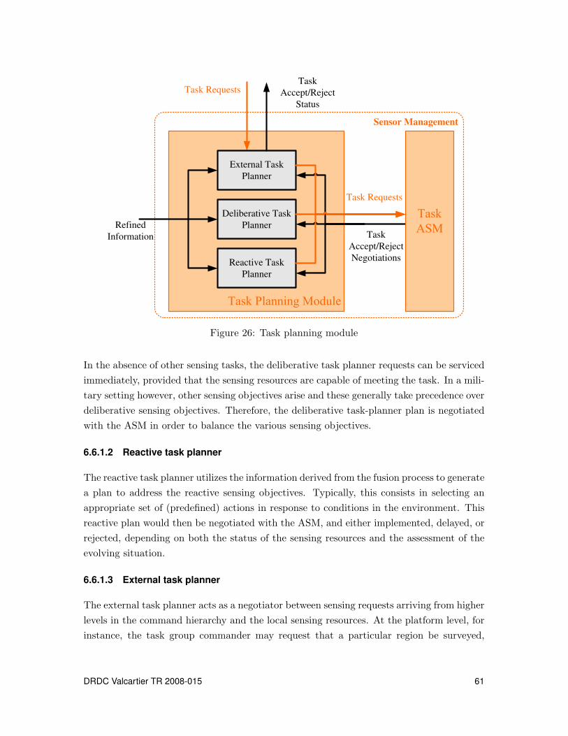
Deliberative Task
Planner
Reactive Task
Planner
Refined
Information
Task Requests
External Task
Planner
Task
Accept/Reject
Status
Task Requests
Task
Accept/Reject
Negotiations
Sensor Management
Figure 26: Task planning module
In the absence of other sensing tasks, the deliberative task planner requests can be serviced
immediately, provided that the sensing resources are capable of meeting the task. In a mili-
tary setting however, other sensing objectives arise and these generally take precedence over
deliberative sensing objectives. Therefore, the deliberative task-planner plan is negotiated
with the ASM in order to balance the various sensing objectives.
6.6.1.2 Reactive task planner
The reactive task planner utilizes the information derived from the fusion process to generate
a plan to address the reactive sensing objectives. Typically, this consists in selecting an
appropriate set of (predefined) actions in response to conditions in the environment. This
reactive plan would then be negotiated with the ASM, and either implemented, delayed, or
rejected, depending on both the status of the sensing resources and the assessment of the
evolving situation.
6.6.1.3 External task planner
The external task planner acts as a negotiator between sensing requests arriving from higher
levels in the command hierarchy and the local sensing resources. At the platform level, for
instance, the task group commander may request that a particular region be surveyed,
DRDC Valcartier TR 2008-015 61

or a particular target tracked. The external task planner translates this request into a
plan, which is negotiated with the ASM. The external task planner provides the requesting
source with feedback detailing the status of the request, as well as other status information
necessary for task allocation, negotiation, and planning.
6.6.2 Task allocation and scheduling
Task allocation and task scheduling are at the heart of the SM problem. Resource allocation
by the ASM must not only balance the immediate task priorities but also the expected future
events and task requests. For example, when allocating tracking sensors to lower priority
targets (e.g., non-threatening targets), it may be better to use a lower accuracy sensor and
reserve the better ones for tracking high-interest targets.
The ASM compares the task requests from the three planning modules (reactive, delibera-
tive, external), shown in Figure 26, to determine the best use of the resources. Negotiations
between the planning modules and the ASM may lead to tasks being implemented, re-
planned, or rejected outright, depending on the evolving situation and the current and
predicted status of the sensors. These negotiation mechanisms are discussed in the next
sub-section.
6.6.3 Task negotiation
The task planners rely on a negotiation process in order to generate and revise task plans.
Within a single SM system, negotiation between the ASM and task planners (internal
negotiation) is crucial to ensure the best performance of the sensing resources. In addition
to this internal type of negotiation, there is the negotiation that the external task planner
conducts with the higher-level sensor manager (external negotiation).
6.6.3.1 Internal negotiations
Internal negotiations provide for an exchange of resource status information and task plans,
so that the most suitable resources can be utilized for the sensing tasks. These negotiations
also help balance the priority of sensing tasks. Although the task planners and the ASM
are treated as independent here, practical implementation typically combines their roles,
and this process of negotiation is implicit to the control strategy.
6.6.3.2 External negotiations
External negotiations are similar but may operate on a different (longer) time scale than the
internal negotiations. These negotiations may be hampered by communication difficulties
62 DRDC Valcartier TR 2008-015

such as bandwidth limitations and poor reliability. External negotiations can be thought
of as two lines of communication, control information (e.g., requests) coming from a higher
level in the control hierarchy and resource information (status or data) flowing upwards in
the hierarchy, as shown in Figures 25 to 27. The ASM negotiations with the task planners
constitute one of the most critical decision-making processes of SM.
6.6.3.3 Task priority
Of primary importance to task negotiation is an assessment of both the priority of the
task and the specification of performance objectives. The objectives guide the choice of
resources to use while the priorities guide the order in which tasks are executed, if at all. In
the model illustrated in Figure 26, the task priority is derived from the information gathered
and produced as output from the planning modules (reactive, deliberative, external) to the
ASM.
6.6.4 Data and control communication
The control problem, as described in the previous paragraphs, involves the communication
of two types of information: control and data. Data flow upwards to the command hierarchy
while control information flows downwards. Figure 27 shows the information flow between
a group-level sensor command and two platforms. This structure can be extended to any
number of hierarchical levels.
The content of the control information depends on the type of controller implemented and
on the control architecture used. It is important to note that SM at each level requires
some knowledge about the status of the resources at the level below. When inter-platform
communications are used to transmit these data, bandwidth limitations and reliability may
influence the choice of the controller as much as performance requirements. On the other
hand, within a single platform, where communication links are typically fast and reliable,
the controller’s performance may become the main concern.
6.6.5 Comparison between conventional and holonic control
We can now summarize some of the primary differences between the holonic system ap-
proach and conventional hierarchical approaches to C2 problems, as shown in Table 222.
22Adapted from [19].
DRDC Valcartier TR 2008-015 63

Table 2: Characteristics of conventional and holonic control approaches
Conventional Hierarchical Control Holonic Control
Fixed layered, hierarchical architecture rep-resenting the different C2 problems
No permanent hierarchy of control problems
Command and response mechanism providesthe basis for the connection between differ-ent C2 problems
Interactive interchange and simultaneous so-lution is possible between different C2 prob-lems
Predetermined solution format to individualC2 problems
Solution format determined by the differentholons involved
Typically a centralized solver for each indi-vidual C2 problem
Typically a distributed solver, with co-operative interactions between nodes
Solution time constrained by processingpower
Solution time constrained by communica-tion speed
Control system architecture effectively de-coupled from control solution
Control system architecture tightly coupledto control solutions
64 DRDC Valcartier TR 2008-015

Task Planning
Task Allocation
and Scheduling
Module (ASM)
Sensing ResourcesFusion
Task Request
Task Accept/
Reject
Negotiations
Task Planning
Task Allocation
and Scheduling
Module (ASM)
Sensing ResourcesFusion
Task Request
Task Accept/
Reject
Negotiations
Task Planning
Task Allocation
and Scheduling
Module (ASM)
Fusion
Task Request
Task Accept/
Reject
Negotiations
Sensor Management
Task Request
Task Accept/Reject
StatusTask Request
Refined
Information
Sensor Management Sensor Management
Task Request Task Request
Task
Accept/Reject
Status
Task
Accept/
Reject
Status
Task
Accept/
Reject
Status
Platform BPlatform A
Command Center
Fig
ure
27:
Sen
sorm
anagem
ent
data
and
comm
and
flow
s
DR
DC
Va
lca
rtier
TR
20
08
-01
56
5

This page intentionally left blank.
66 DRDC Valcartier TR 2008-015
7 Conclusion and recommendations
Military tactical surveillance is typically achieved through a network of high value and
powerful sensors dispersed throughout the theatre of operations. The control and coordi-
nation of a distributed sensor network is a very challenging task, which is assumed by the
automated process of SM.
In the military setting, SM is hierarchical and recursive in nature, which means it can be
decomposed into a series of smaller but similar control problems at different levels of the hi-
erarchy. Several control architectures, ranging from centralized to completely decentralized,
were considered in the context of military SM.
Centralized control architectures are inappropriate for SM because they are inflexible and
require replanning when faced with changes in the environment. In addition, the architec-
ture relies on the operation of a single command node and performance is linked directly to
communication between this node and the resources. In military situations, this approach
is simply not robust enough to be relied upon.
The decentralized and/or heterarchical control architecture, although more robust, is inap-
propriate for military SM as no specific chain of command can be maintained. In addition,
the overall behaviour of a network of sensors in a decentralized type of control is difficult
to predict and is potentially chaotic.
The holonic control architecture is a superior choice for SM in the military settings because
it is naturally hierarchical and recursive. A holonic architecture maintains the chain of
command, is robust and flexible, and its overall behaviour is predictable. A review of
holonic systems was presented and the feasibility of the application of the holonic control
methodology to tactical SM demonstrated.
It was also shown that SM can be viewed as a complex control problem. Several con-
trol techniques including classical control theory, discrete event control, optimization, and
learning systems, were reviewed during this study and their benefits and disadvantages
discussed.
For any holon, the control problem is either continuous or discrete. Continuous type prob-
lems involve the execution of SM task plans. Typically, task execution involves regular
updates of control commands in order to meet performance objectives. Continuous type
control problems can be addressed by the classical control theory at the resource level.
Discrete control problems involve the planning of SM tasks in response to new events oc-
curring in the environment and/or the issuing of new sensing objectives. Discrete control
DRDC Valcartier TR 2008-015 67

problems can be best addressed by discrete event systems or the Petri-Net formulation.
Taken together, it is evident that the control aspect of SM can be met by a hybrid combi-
nation of discrete event control for task planning and decision/optimization theory for task
implementation.
Based on the presented review, it is recommended that the holonic control architecture be
used to address the hierarchical and recursive SM problem in military settings. For this,
SM control must be tailored for each level of the hierarchy and for each node in it. It is
recommended to use hybrid control, consisting of combination of discrete event approaches
and decision theory/optimization or classical control theory.
Implementation of the above control approach requires the development of performance
metrics for each level of the hierarchy. An idealized simulation of SM in the military should
be developed in order to demonstrate these concepts. It is recommended that the detailed
control design follow the development of metrics that are devised for individual management
systems within each level.
In subsequent tasks of this project, it is planned to develop a simulation to demonstrate
the viability of holonic control applied to SM.
68 DRDC Valcartier TR 2008-015
References
[1] Benaskeur, A. and Irandoust, H. (2007), Sensor management for tactical surveillance
operations, Technical Report DRDC Valcartier.
[2] Sandell, Nils R., Varaiya, Pravin, Athans, Michael, and Safonov, Michael G. (1978),
Survey of Decentralized Control Methods for Large Scale Systems, IEEE
Transactions on Automatic Control, AC-23(2), 108–128.
[3] Parunak, H. V. (1996), Foundations of distributed artificial intelligence,
Ch. Applications of Distributed Artificial Intelligence in Industry, pp. 139–164, New
York, NY, USA: John Wiley & Sons, Inc.
[4] Mesanovic, M., Macko, D., and Takahara, Y. (1970), Theory of hierarchical,
multilevel systems.
[5] Singh, M. G. (1980), Dynamic Hierarchical Control, Revised Edition, North-Holland.
[6] Jamshidi, M. (1983), Large-Scale Systems: Modelling and Control, North-Holland.
[7] Dantzig, G. B. and Wolfe, P. (1960), Decomposition principle for linear programs,
Operations Research, 8, 101–111.
[8] Gershwin, S.B. (1989), Hierarchical flow control: a framework for scheduling and
planning discrete events in manufacturing systems, In Proceedings of the IEEE,
Vol. 77, pp. 195–209.
[9] Jones, A. and Saleh, A. (1990), A multi-level/multi-layer architecture for intelligent
shopfloor control, International Journal of Computer Integrated Manufacturing, 3,
60–70.
[10] Geoffrion, A. (1970), Elements of Large-Scale Mathematical Programming, Parts I
and II, Management Science, 16(11), 652–691.
[11] Benders, J. (1962), Partitioning Procedures for Solving Mixed Variables
Programming Problems, Numerische Mathematik, 4, 238–252.
[12] Hax, A. C. and Meal, H.C. (1975), Hierarchical integration of production planning
and scheduling, In Geisler, M. A., (Ed.), Studies in management sciences: Vol. 1,
logistics, pp. 53–69, New York: Elsevier.
[13] Albus, J. S., Quintero, R., Lumia, R., Herman, M., Kilmer, R., and Goodwin, K.
(1990), Concept for a Reference Model Architecture for Real-Time Intelligent Control
Systems (ARTICS). NIST Technical Note 1277.
DRDC Valcartier TR 2008-015 69

[14] Dilts, D.M., Boyd, N.P., and Whorms, H.H. (1991), The evolution of control
architectures for automated manufacturing systems, Journal of Manufacturing
Systems, 10, 79–93.
[15] Rana, S. P. and Taneja, S. K. (1988), A distributed architecture for automated
manufacturing systems, International Journal of Advanced Manufacturing
Technology, 3(5), 81–98.
[16] Davis, R. and Smith, R. G. (1983), Negotiation as a metaphor for distributed
problem solving, Distributed Artificial Intelligence, 20, 333–356.
[17] Parunak, H. V. (1987), Manufacturing Experience with the Contract Net, In Huhns,
M., (Ed.), Distributed Artificial Intelligence, pp. 285–310, Pitman Publishing:
London and Morgan Kaufmann: San Mateo, CA.
[18] Shen, W. and Norrie, D. H. (1999), Agent-Based Systems for Intelligent
Manufacturing: A State-of-the-Art Survey, Knowledge and Information Systems,
1(2), 129–156.
[19] McFarlane, D.C. and Bussmann, S. (2000), Developments in holonic production
planning and control, Production Planning and Control, 11(6), 522–536.
[20] Enslow, P.H. Jr (1978), What is a distributed data processing system?, Computer, 1,
13–21.
[21] Vamos, T. (1983), Cooperative Systems - An Evolutionary Perspective, IEEE Control
Systems Magazine, 3(2), 9–14.
[22] Hatvany, J. (1984), Intelligence and cooperation in heterarchic manufacturing
systems, Robotics and Computer-Integrated Manufacturing, 2(2), 101–104.
[23] Smith, Reid G. (1981), The Contract Net Protocol: High-Level Communication and
Control in a Distributed Problem Solver, IEEE Transactions on Computers,
C-29(12), 1104–1113.
[24] Duffie, N. and Piper, R. (1986), Nonhierarchical control of manufacturing systems,
Journal of Manufacturing Systems, 5(2), 137–139.
[25] Duffie, N. and Prabhu, V.V. (1994), Real-time distributed scheduling of heterarchical
manufacturing systems, Journal of Manufacturing Systems, 13(2), 94–107.
[26] McGuire, J. G., Kuokka, D. R., Weber, J. C., Tenenbaum, J. M., Gruber, T. R., and
Olsen, G. R. (1993), SHADE: Technology for Knowledge-Based Collaborative
70 DRDC Valcartier TR 2008-015
Engineering, Journal of Concurrent Engineering: Applications and Research
(CERA), 1(2).
[27] Park, H., Cutkosky, M., Conru, A., and Lee, S.H. (1994), An agent-based approach
to concurrent cable harness design, AIEDAM, 8(1), 45–62.
[28] Decker, K., Sycara, K., and Williamson, M. (1997), Middle-Agents for the Internet,
In Proceedings of the 15th International Joint Conference on Artificial Intelligence,
Nagoya, Japan.
[29] Wiederhold, G. (1992), Mediators in the architecture of future information systems,
IEEE Computer, 25(3), 38–49.
[30] Gaines, B.R., Norrie, D.H., and Lapsley, A.Z. (1995), Mediator: an Intelligent
Information System Supporting the Virtual Manufacturing Enterprise, In Proceedings
of the 1995 IEEE Conference of Systems, Man, and Cybernetics, pp. 964–969.
[31] Christensen, J. (1994), HMS: Initial Architecture and Standards Directions, In
Proceedings of the 1st European Conference on Holonic Manufacturing Systems,
Berlin University, Germany., pp. 1–20.
[32] Pao, L. and Baltz, N (1999), Control of Sensor Information in Distributed
Multisensor Systems, In Proceedings of the American Control Conference, Vol. 1,
pp. 2397–2401, San Diego, CA.
[33] Kalandros, M and Pao, L. (1998), Controlling Target Estimate Covariance in
Centralized Multisensor System, In Proceedings of the American Control Conference,
Vol. 1, pp. 1177–1180, Philadelphia, PA.
[34] Moody, J. O. (1998), Petri Net Supervisors For Discrete Event Systems, Ph.D. thesis,
University of Notre Dame, Indiana, USA.
[35] Moody, J. O. and Antsaklis, P. J. (1998), Supervisory Control of Discrete Event
Systems Using Petri Nets, Norwell, MA, USA: Kluwer Academic Publishers.
[36] King, Jamie, Pretty, R. K., and Gosine, Ray G. (2003), Coordinated execution of
tasks in a multiagent environment., IEEE Transactions on Systems, Man, and
Cybernetics, Part A, 33(5), 615–619.
[37] Nash, Jeffrey. M. (1977), Optimal Allocation of Tracking Resources, In Proceedings of
the 1977 IEEE Conference on Decision and Control, New Orleans, LA, 1, 1177–1180.
DRDC Valcartier TR 2008-015 71

[38] Schmaedeke, W. (1993), Information based Sensor Management, Signal Processing,
Sensor Fusion, and Target Recognition II. Proceedings of the SPIE - The
International Society for Optical Engineering , Orlando, FL, 1955, 156–164.
[39] Malhotra, R. (1995), Temporal Considerations in Sensor Management, Proceedings of
the IEEE 1995 National Aerospace and Electronics Conference, NAECON, Dayton,
OH, 1, 86–93.
[40] Washburn, R., Chao, A., Castanon, D., Bertsekas, D., and Malhotra, R. (1997),
Stochastic Dynamic Programming for Far-Sighted Sensor Management, IRIS
National Symposium on Sensor and Data Fusion.
[41] Castanon, D. (1995), Optimal Search Strategies in Dynamic Hypothesis Testing,
IEEE Transactions on System, Man, and Cybernetics, 25(7), 1130–1138.
[42] D’Ambrosio, B. and Fung, R. (1996), Far-Sighted Decision Theoretic Sensor
Management, Technical Report prepared for Wright Laboratory, Wright-Patterson
AFB, OH.
[43] Grocholsky, B. (2002), Information-Theoretic Control of Multiple Sensor Platforms,
Ph.D. thesis, The University of Sydney. Available from http://www.acfr.usyd.edu.au.
[44] Cook, D.J., Gmytrasiewicz, P., and Holder, L. B. (1996), Decision-Theoretic
Cooperative Sensor Planning, IEEE Trans. Pattern Anal. Mach. Intell., 18(10),
1013–1023.
[45] Barto, A.G. and Sutton, R.S. (1998), Reinforcement Learning, An Introduction, MIT
Press.
[46] Kreucher, C., Kastella, K., and Hero, A.O. (2003), A Bayesian method for integrated
multitarget tracking and sensor management, Proceedings of the Sixth International
Conference of Information Fusion, 1, 704 – 711.
[47] Albus, J.S. (1975), A New Approach to Manipulator Control: The Cerebellar Model
Articulation Controller (CMAC), Journal of Dynamic Systems, Measurement and
Control, American Soc. of Mechanical Engineers, 97(3), 312–324.
[48] Koestler, A. (1967), The Ghost in the Machine.
[49] Koestler, A. (1978), Janus: A Summing Up, Hutchinson, U.K.
[50] Bussmann, S. (1998), An agent-oriented architecture for holonic manufacturing
control, In Proceedings of First International Workshop on Intelligent Manufacturing
Systems (IMS), pp. pp. 1–12., EPFL, Lausanne, Switzerland.
72 DRDC Valcartier TR 2008-015
[51] Simon, H. (1996), The Sciences of the Artificial, M.I.T. Press.
[52] Brussel, H. Van, Wyns, J., Valckenaers, P., Bongaerts, L., and Peeters, P. (1998),
Reference architecture for holonic manufacturing systems: PROSA, Computers in
Industry, 37(3), 255–274.
[53] Maturana, F.P. and Norrie, D.H. (1996), Multi-agent mediator architecture for
distributed manufacturing, Journal of Intelligent Manufacturing, 7, 257–270.
[54] Fletcher, M., Garcia-Herreros, E., Christensen, J. H., Deen, S. M., and Mittmann, R.
(2000), An Open Architecture for Holonic Cooperation and Autonomy, In
Proceedings of the 11th International Workshop on Database and Expert Systems
Applications, p. 224, Washington, DC, USA: IEEE Computer Society.
[55] Weiss, G. (1999), Multiagent Systems: A Modern Approach to Distributed Artificial
Intelligence, Cambridge, MA: The MIT Press.
[56] Moulin, B. and Chaıb-draa, B. (1996), Foundations of distributed artificial
intelligence, Ch. An overview of distributed artificial intelligence, pp. 3–55, New
York, NY, USA: John Wiley & Sons, Inc.
[57] Huhns, M. and Singh, M. (1998), Readings in Agents, Morgan Kaufmann, Los
AeEos, CA.
[58] Boosh, G. (1994), Object-Oriented Analysis and Design (second edition), Reading,
MA: Addison-Wesley.
[59] Parunak, H. V. (1993), Autonomous agent architectures: A non technical
introduction. Industrial Technology Institute.
[60] Wooldridge, M. J. and Jennings, N. R. (1999), Software Engineering with Agents:
Pitfalls and Pratfalls, IEEE Internet Computing, 3(3), 20–27.
[61] Shen, W., Maturana, F., and Norrie, D. (2000), MetaMorph II: an agent-based
architecture for distributed intelligent design and manufacturing, Journal of
Intelligent Manufacturing - Special Issue on Distributed Manufacturing Systems,
11(3), 237–251.
[62] Rao, A. S. and Georgeff, M. P. (1991), Modeling agents within a BDI-Architecture,
In Proceedings of the Second International Conference on Principles of Knowledge
Representation and Reasoning, pp. 473–484, Morgan Kaufmann.
[63] Brooks, R. (1987), A Robust Layered Control System for a Mobile Robot, IEEE
Journal of Robotics and Automation, 2(1), 14–23.
DRDC Valcartier TR 2008-015 73
[64] Franklin, S. (1997), Autonomous agents as embodied AI, Cybernetics and Systems,
28, 499–520.
[65] Hayes-Roth, B. (1991), An integrated architecture for adaptive intelligent systems,
Artificial Intelligence, 26(3), 329–365.
[66] Ishida, T. (1994), Parallel, Distributed and Multiagent Production Systems,
Secaucus, NJ, USA: Springer-Verlag New York, Inc.
[67] Giret, A. and Botti, V. (2004), Holons and Agents, Journal of Intelligent
Manufacturing, 15, 645–659.
[68] Foundation for Intelligent Physical Agents (2004), FIPA ACL Message Structure
Specification. Document Identifier SC00061. http://www.fipa.org/specs/fipa00061.
[69] Vrba, P. (2003), Java-based agent platform evaluation, Holonic and Multi-agent
Systems for Manufacturing, In Lecture Notes in Artificial Intelligence 2744,
pp. 47–58.
74 DRDC Valcartier TR 2008-015

List of Acronyms
AI Artificial IntelligenceASM Allocation and Scheduling ModuleAWW Above Water WarfareANN Artificial Neural NetworksBDI Belief-Desire-IntentionC2 Command & ControlCMAC Cerebellar Model Articulation ControllerDES Discrete Event SystemDDPS Distributed Data Processing SystemsDEC Discrete Event ControlDES Discrete Event SystemECCM Electronic Counter-Counter MeasuresESA Electronically Scanned ArrayFSM Finite State MachineFIPA Foundation for Intelligent Physical AgentsHIT High Interest TargetHLC High-Level-ControlHMS Holonic Manufacturing SystemHVU High Value UnitLPI Low Probability of InterceptionMAS Multi-Agent SystemNN Neural NetworksPN Petri-NetPROSA Product-Resource-Order-Staff ArchitecturePOMDP Partially Observable Markov Decision ProcessSCADA Supervisory Control and Data AcquisitionRH Resource HolonSICH Service Interface Command HolonSM Sensor ManagementTH Task HolonTD Temporal DifferencingUAV Unmanned Aerial VehicleVOI Volume of InterestYAMS Yet Another Manufacturing System
DRDC Valcartier TR 2008-015 75
This page intentionally left blank.
76 DRDC Valcartier TR 2008-015
Distribution list
DRDC Valcartier TR 2008-015
Internal distribution
1 Director General
3 Document Library
1 Head/C2 Decision Support Systems
1 M. Belanger
1 P. Maupin
1 Dr P. Valin
1 Head/Intelligence and Information
1 R/Visualization & Geo-spatial Systems
1 R/Knowledge Management
1 R/Intelligence Production and Exploitation
1 Head/System of Systems
1 R/Characterization and Exploration
1 R/Engineering & Architecture
1 R/Security and Robustness
1 Ltv. L. St-Pierre
1 Maj. A. Lamontagne
1 Dr M. Allouche
1 Dr A. Benaskeur (author)
1 J. Berger
1 M. Blanchette
1 Dr A. Boukhtouta
DRDC Valcartier TR 2008-015 77

1 Dr R. Breton
1 E. Dorion
1 Dr A. Guitouni
1 Dr H. Irandoust (author)
1 Dr A.-L. Jousselme
1 L. Pigeon
1 F. Rheaume
1 A. Sahi
Total internal copies: 31
78 DRDC Valcartier TR 2008-015

External distribution
1 Library and Archives Canada
395 Wellington Street Ottawa, ON, K1A 0N4
1 Director Research and Development Knowledge and Information Management (PDF
file)
1 Director Science & Technology Maritime(DSTM)
Constitution Building, 305 Rideau St., Ottawa, ON, K1N 9E5
1 Director Science & Technology Land (DSTL)
Constitution Building, 305 Rideau St., Ottawa, ON, K1N 9E5
1 Director Science & Technology Air (DSTA)
Constitution Building, 305 Rideau St., Ottawa, ON, K1N 9E5
1 Director Science & Technology C4ISR (DSTC4ISR)
Constitution Building, 305 Rideau St., Ottawa, ON, K1N 9E5
1 Director Maritime Requirements Sea (DMRS) 4
Louis St. Laurent Bldg, 555 Boul. de la Carriere, Gatineau, QC, J8Y 6T5
1 Director Maritime Requirements Sea (DMRS) 6
Louis St. Laurent Bldg, 555 Boul. de la Carriere, Gatineau, QC, J8Y 6T5
1 Director Aerospace Requirements (DAR) 4
101 Colonel By Drive, Ottawa, ON, K1A 0K2
1 Director Aerospace Requirements (DAR) 4-2
101 Colonel By Drive, Ottawa, ON, K1A 0K2
1 Director Maritime Ship Support (DMSS) 6
Louis St. Laurent Bldg, 555 Boul. de la Carriere, Gatineau, QC, J8Y 6T5
1 Director Maritime Ship Support (DMSS) 8
Louis St. Laurent Bldg, 555 Boul. de la Carriere, Gatineau, QC, J8Y 6T5
2 DRDC - Atlantic:
Attn: Dr. Bruce MacArthur
Attn: Dr. Jim S. Kennedy
2 DRDC - Ottawa:
Attn: Barbara Ford
Attn: Dan Brookes
DRDC Valcartier TR 2008-015 79

2 CF Maritime Warfare School CFB Halifax
PO Box 99000
Stn Forces
Halifax, Nova Scotia, B3K 5X5
Attn: TAC AAW
OIC Modeling and Simulation
2 Canadian Forces Naval Operations School CFB Halifax
PO Box 99000
Stn Forces
Halifax, Nova Scotia, B3K 5X5
Attn: Tactic
CT AWW
1 Canadian Forces Naval Engineering School CFB Halifax
PO Box 99000
Stn Forces
Halifax, Nova Scotia, B3K 5X5
Attn: CSTC
1 Operational Requirements Analysis Cell CFB Halifax
PO Box 99000
Stn Forces
Halifax, Nova Scotia, B3K 5X5
Attn: Commanding Officer
1 Canadian Forces Fleet School CFB Esquimalt
P.O. Box 17000
Stn Forces
Victoria, British Columbia, V9A 7N2
Attn: Commanding Officer/WTD
1 Operational Requirements Analysis Cell CFB Esquimalt
P.O. Box 17000
Stn Forces
Victoria, British Columbia, V9A 7N2
Attn: Commanding Officer
Total external copies: 24
Total copies: 55
80 DRDC Valcartier TR 2008-015
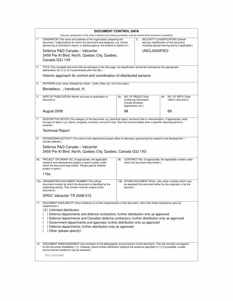
DOCUMENT CONTROL DATA(Security classification of title, body of abstract and indexing annotation must be entered when document is classified)
1. ORIGINATOR (The name and address of the organization preparing the
document. Organizations for whom the document was prepared, e.g. Centre
sponsoring a contractor’s report, or tasking agency, are entered in section 8.)
Defence R&D Canada – Valcartier
2459 Pie-XI Blvd. North, Quebec City, Quebec,
Canada G3J 1X5
2. SECURITY CLASSIFICATION (Overall
security classification of the document
including special warning terms if applicable.)
UNCLASSIFIED
3. TITLE (The complete document title as indicated on the title page. Its classification should be indicated by the appropriate
abbreviation (S, C or U) in parentheses after the title.)
Holonic approach for control and coordination of distributed sensors
4. AUTHORS (Last name, followed by initials – ranks, titles, etc. not to be used.)
Benaskeur, .; Irandoust, H.
5. DATE OF PUBLICATION (Month and year of publication of
document.)
August 2008
6a. NO. OF PAGES (Total
containing information.
Include Annexes,
Appendices, etc.)
98
6b. NO. OF REFS (Total
cited in document.)
69
7. DESCRIPTIVE NOTES (The category of the document, e.g. technical report, technical note or memorandum. If appropriate, enter
the type of report, e.g. interim, progress, summary, annual or final. Give the inclusive dates when a specific reporting period is
covered.)
Technical Report
8. SPONSORING ACTIVITY (The name of the department project office or laboratory sponsoring the research and development –
include address.)
Defence R&D Canada – Valcartier
2459 Pie-XI Blvd. North, Quebec City, Quebec, Canada G3J 1X5
9a. PROJECT OR GRANT NO. (If appropriate, the applicable
research and development project or grant number under
which the document was written. Please specify whether
project or grant.)
11bs
9b. CONTRACT NO. (If appropriate, the applicable number under
which the document was written.)
10a. ORIGINATOR’S DOCUMENT NUMBER (The official
document number by which the document is identified by the
originating activity. This number must be unique to this
document.)
DRDC Valcartier TR 2008-015
10b. OTHER DOCUMENT NO(s). (Any other numbers which may
be assigned this document either by the originator or by the
sponsor.)
11. DOCUMENT AVAILABILITY (Any limitations on further dissemination of the document, other than those imposed by security
classification.)
( X ) Unlimited distribution
( ) Defence departments and defence contractors; further distribution only as approved
( ) Defence departments and Canadian defence contractors; further distribution only as approved
( ) Government departments and agencies; further distribution only as approved
( ) Defence departments; further distribution only as approved
( ) Other (please specify):
12. DOCUMENT ANNOUNCEMENT (Any limitation to the bibliographic announcement of this document. This will normally correspond
to the Document Availability (11). However, where further distribution (beyond the audience specified in (11)) is possible, a wider
announcement audience may be selected.)
Unlimited
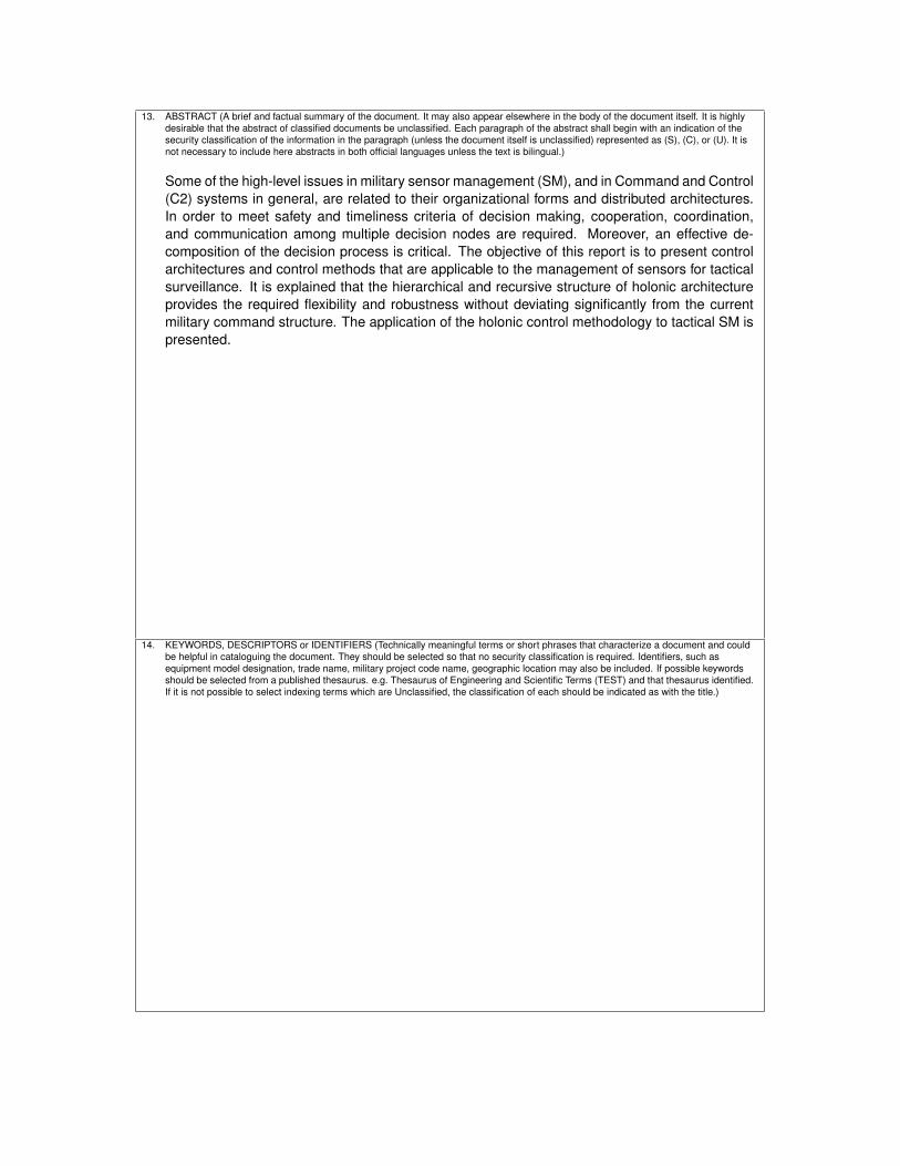
13. ABSTRACT (A brief and factual summary of the document. It may also appear elsewhere in the body of the document itself. It is highly
desirable that the abstract of classified documents be unclassified. Each paragraph of the abstract shall begin with an indication of the
security classification of the information in the paragraph (unless the document itself is unclassified) represented as (S), (C), or (U). It is
not necessary to include here abstracts in both official languages unless the text is bilingual.)
Some of the high-level issues in military sensor management (SM), and in Command and Control
(C2) systems in general, are related to their organizational forms and distributed architectures.
In order to meet safety and timeliness criteria of decision making, cooperation, coordination,
and communication among multiple decision nodes are required. Moreover, an effective de-
composition of the decision process is critical. The objective of this report is to present control
architectures and control methods that are applicable to the management of sensors for tactical
surveillance. It is explained that the hierarchical and recursive structure of holonic architecture
provides the required flexibility and robustness without deviating significantly from the current
military command structure. The application of the holonic control methodology to tactical SM is
presented.
14. KEYWORDS, DESCRIPTORS or IDENTIFIERS (Technically meaningful terms or short phrases that characterize a document and could
be helpful in cataloguing the document. They should be selected so that no security classification is required. Identifiers, such as
equipment model designation, trade name, military project code name, geographic location may also be included. If possible keywords
should be selected from a published thesaurus. e.g. Thesaurus of Engineering and Scientific Terms (TEST) and that thesaurus identified.
If it is not possible to select indexing terms which are Unclassified, the classification of each should be indicated as with the title.)


Canada’s Leader in Defence
and National Security
Science and Technology
Chef de file au Canada en matière
de science et de technologie pour
la défense et la sécurité nationale
www.drdc-rddc.gc.ca
Defence R&D Canada R & D pour la défense Canada