Embed Size (px)
Citation preview

Page 1
HOLISTIC MULTISCALE SIMULATION APPROACH FOR ADDITIVE LAYER MANUFACTURING OF PLASTICS
Philippe Hébert, Sylvain Mathieu, Laurent Adam e-Xstream engineering
Dominique Gianotta, Charlotte Basire Solvay Engineering Plastics
Abstract Additive layer manufacturing (ALM) of plastics has been rapidly developing over the last few
years, notably with plastics and reinforced plastics applications. To ensure competitiveness of the additive manufacturing process, some requirements must be met, such as replicability of process and part performance, and addressing needs of high performance industrial applications. Inherent complexity of additive manufacturing calls for a need of simulation tools to unveil the full potential offered by the manufacturing technology, allowing to predict effect of any parameters on process and part performance.
A holistic simulation approach is presented, covering process, material and structural engineering for both SLS and FFF applications. ALM process simulation of plastics will be discussed, describing methodologies which enable to predict warpage of final part as a function of the printing pattern and other process related parameters. Material models enabling to capture the true local, anisotropic and non-linear behavior of ALM material systems will be presented, focusing on multi-scale modeling techniques. Finally, a procedure will be demonstrated to allow prediction of as-manufactured plastic part performance, via strongly coupled process-structure simulation approach, ultimately opening the door to optimization of part performance prior to physical prototyping.
Introduction Plastic part complexity has historically been strongly driving part cost. Recent developments
of additive techniques have enabled a shift from rapid prototyping to actual production of industrial parts, thus allowing an extended range of design possibilities notably for automotive applications. Additive layer manufacturing (ALM), by definition opposed to subtractive methods, regroups a number of manufacturing processes allowing to create parts from 3D numerical CAD model by building them layer-by-layer, hence not requiring specific mold tooling design. Low volume, complex parts can be produced at fixed cost in less time. Several ALM processes are applicable to plastics and reinforced plastics. Mostly used in the industry today are the selective laser sintering process (SLS) and fused filament fabrication (FFF), sometimes also referred to as fused deposition modeling (FDM). In SLS, powdered material is sintered using a laser heat source while in FFF material filaments are deposited through a moving head.
Both SLS and FFF are applicable to plastics and reinforced plastics. However the use of such manufacturing techniques today involves coping with major challenges. Produced part may show important warpage due to thermally induced part distortion, thus dimensional tolerance may not be ensured. Material behavior is strongly impacted by 3D printing pattern, usually leading to anisotropic behavior even for non-reinforced plastics. ALM induces a strong link between process and material performance, driving the final part end performance.

Page 2
To ensure industrial deployment of ALM some requirements must be met:
• offering strong replicability of process and part performance: full control of process parameters and their influence on the process quality and part performance must therefore be obtained
• addressing needs of high performance industrial applications: optimization of the process induced performance of parts made of reinforced plastics must be possible
Additive layer manufacturing offers by nature the widest range of design possibilities, but also the most important complexity, involving many trial and error to reach consistency and expected performance. To meet the requirements of the industry, engineers must rely on simulation, whether for process engineering, material engineering or structural engineering.
The present paper is proposing a holistic simulation approach for additive layer manufacturing (SLS and FFF), covering all three aspects mentioned above:
• material engineering: multi-scale modeling techniques are presented to capture the non-linear process dependent material behavior
• process engineering: prediction of warpage by means of thermo-mechanical finite element analysis are shown
• structural engineering: prediction of mechanical response of ALM parts by strongly coupled process-structure simulation approach, allowing optimization of part performance as a function of the printing direction
The technology presented in the paper is then applied and validated against experimental data for an automotive SLS application.
Material engineering The additive manufacturing process has a direct influence on the material behavior, whether
for SLS or FFF processes. It is thus of paramount importance to model the link between process and material behavior via simulation. While many process parameters are available, the present paper focuses on the effect of the printing direction, for both SLS and FFF.
Fused Filament Fabrication
Fused Filament Fabrication consists in depositing material filaments through a moving head. The superposition of the filaments – or beads – induces some specific microstructures based on the printing pattern. Such microstructures are shown in the illustration below, where beads have been simplified into straight cylinders showing a given interpenetration.
Page 3
Figure 1 Typical bead deposition patterns for FFF
The two deposition patterns considered are 0°/90° alternative layers (Figure 1 a)) and unidirectional 0° printing direction (Figure 1 b)). From these idealization of the bead deposition process, it can be seen that porosity is induced, with a given volume fraction, but also a given direction. The induced microstructure is summarized in the table below.
Table I FFF induced porosity for various printing directions
Induced microstructure
Printing pattern a) 0°/90° b) 0°
Void volume fraction 6.4% 8.3%
The FFF material, even when considering a pure polymer, therefore shows heterogeneities, ultimately leading to anisotropy in its behavior. As heterogeneous material properties depend on the material microstructure including void volume fraction and orientation, they are adequately modeled from micromechanics. A micromechanical approach is investigated to model such material showing heterogeneities: mean-field homogenization.
Mean-field homogenization combines the properties of each constituent of a multi-phase material and the description of the microstructure to compute equivalent anisotropic homogeneous properties from the original heterogeneous material. This technology has been applied on a wide range of materials. While mean-field homogenization is usually applied on fiber reinforced materials to model the effect of stiff inclusions, it can also be extended to void inclusions, which can be idealized as reinforcements showing no stiffness.
The non-linear response of the material is evaluated for both printing patterns, using the Digimat-MF software which implements the Mori-Tanaka homogenization scheme [1] [2]. Bead is modeled as a homogeneous material described by a J2-plasticity model, while porosity is modeled by void ellipsoidal inclusions, as required by Mori-Tanaka theory assumptions, for which the shape is approximated by an aspect ratio value of 100. Configuration a) requires to model half of the inclusions purely aligned with the X axis (i.e. theta = 90°, phi = 0°, with theta the XZ angle and phi the XY angle) and half of the inclusions purely aligned with the Y axis (i.e.

Page 4
theta = 90°, phi = 90°) , while configuration a) requires to define inclusions purely aligned with the X axis (i.e. theta = 90°, phi = 0°). By geometrical construction, configuration a) shows in-plane isotropy while configuration b) shows symmetry between Y and Z directions.
Performing homogenization of the microstructures yields the following responses. It can be seen that both configurations show a softer response than the pure polymer, which is a direct consequence of the presence of porosity. However, porosity also induces anisotropy because of its preferential directions. As expected, configuration b) shows the highest level of anisotropy, hence demonstrating that FFF printing pattern can control the material anisotropy.
Figure 2 Mean-field homogenization of FFF typical microstructures
Selective Laser Sintering
Selected Laser Sintering process consists of the sintering of powdered material using a laser heat source. Once a layer is sintered following the expected section, an additional layer of powder is deposited from the powder bed, and a new sintering step can be applied. Typical plastics which can be used with SLS include polyamide. Material modeling of polyamide 6 reinforced with 40% glass beads is considered in the following.
Material characterization of Sinterline® grade from Solvay targets effect of printing direction. Plates have been printed using the SLS process, as shown on the figure below. From the plate, specimen have been cut out every 15° angle, with 0° being the in-plane reference, and 90° the powder bed progression direction.

Page 5
Figure 3 Specimen cutting from SLS printed plate
Specimens have then been tested both in tension and compression in order to obtain the effect of printing direction on the material response. When analyzing the observed material response, very little anisotropy is shown from a stiffness point of view, whether in tension or compression. However, still from a stiffness and plasticity point of view, a pressure sensitivity is highlighted, as compressive response shows a distinctly stiffer response. For a given type of loading (tension or compression), while little anisotropy is observed for stiffness, strain at failure is exhibiting strong anisotropy, with 0° strength almost twice the 90° strength. In other words, maximal strength is reached when material is loaded in the directions of the layer, while minimum strength is reached when material is loaded in the direction of powder bed progression.
Figure 4 Tensile response of Sinterline® at several loading angles compared to printing direction

Page 6
Figure 5 Compressive response of Sinterline® at several loading angles compared to printing direction (refer to Figure 4 for color legend)
Based on these experimental observations, a first modeling approach for the SLS PA6-GB40 material is chosen as following:
• Polyamide constituent behavior is described by a pressure sensitive material model: a generalized version [1] of the Drucker-Prager model [3] has been selected. Composite behavior is obtained by mean-field homogenization of the elastoplastic matrix with elastic glass beads
• Failure anisotropy as a function of the loading direction is described by a Tsai-Wu Transversely Isotropic failure criterion [1]:
(1)
The Tsai-Wu Transversely Isotropic failure criterion requires five parameters:
• Xt: axial tensile strength
• Xc: axial compressive strength
• Yt: transverse tensile strength
• Yc: transverse compressive strength
• S: shear strength From the equation, it can be seen that it assumes material isotropy in the 2-3 plane.

Page 7
The calibration of the material model parameters is done inside Digimat to ensure the best fit with the experimental data. Failure model calibration results are shown below. While a very good fit between model and experiment is achieved for 0°, 45° and 90°, other directions show a less good fit. However, since the observed experimental data standard deviation is at maximum 5.7 MPa, the current fit is considered as satisfying and the model is judged sufficient to represent the evolution of material strength as a function of the loading direction.
Figure 6 Comparison of material failure model with experimental data for various loading angles
The final material model is thus capable of representing two keys aspects of the sintered polyamide material which were identified during the experimental characterization campaign:
• Pressure sensitivity of the plasticity via the Drucker-Prager model
• Anisotropy of failure via a Tsai-Wu 3D Transversely Isotropic failure indicator
By taking into account those key aspects, the material model can predict non-linear material response and failure for any generalized 3D loadings such as those which can be encountered in FEA analysis of structural parts. An application and validation of the material model is proposed in the Structural engineering section of the paper.
Process engineering As discussed in the introduction, one of the biggest challenges in ALM is to ensure the
process consistency and especially to control the warpage induced by the thermo-mechanical loadings involved in the manufacturing process. A simulation approach of the manufacturing process can help to quickly understand at virtually zero marginal cost the sensitivity of process parameters on the process performance. From a global point of view, the goal of ALM process engineering can be summarized as the following:

Page 8
• Predict final distorted shape of a part
• Predict residual stresses distributions
• Predict process induced microstructure such as porosity and fiber orientation (for reinforced plastics)
The predictions of ALM simulations must account for material characteristics and process parameters, which can be a function of the type of ALM process considered. This section will focus on SLS and FFF.
The general workflow for process simulation is however independent of the type of ALM process. Based on the initial part geometry and the material specifications, ALM process is further defined via the tool path and the process parameters, as well as the definition of supports and parts positioning. This description of the process set up serves as input for the thermomechanical simulation which will actually model the ALM process. The bead deposition (FFF) or powder laser sintering (SLS) needs to be modeled, which requires to account for material state evolution, to model the stress build-up as well as the stress relaxation which can occur over time, especially following predefined heat treatments. Once the thermomechanical simulation is performed, then residual stresses can be obtained as well as the final deformed shape of the part.
Fused Filament Fabrication
A generic example of FFF process simulation results is shown here after. Material considered is ABS, which requires to model:
• Isotropic elastic material response with thermal dependency of Young’s modulus
• Isotropic thermal expansion with thermal dependency
• Specific heat
• Thermal conductivity
Part considered is a corner part. Support is idealized via clamping of all bottom nodes, which are released at the end of the thermo-mechanical simulation. Process parameters are summarized in the table below.
Table 2 Process parameters used for corner part application
FFF process parameters
Material temperature from printing head (°C) 280
Processing chamber temperature (°C) 70
Final temperature (°C) 23
Printing head speed (mm/s) 16
Bead width (mm) 1
Layer thickness (mm) 0.254

Page 9
The process simulation of the part aimed at evaluation the effect of the printing direction on the warpage. A comparison is made for two printing patterns:
• Printing along an arm
• Printing along depth
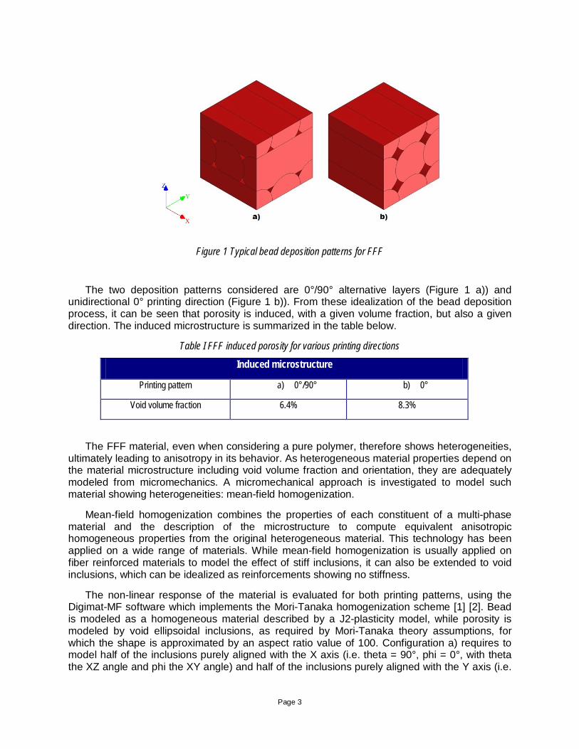
The results of the thermos-mechanical simulations are presented below. It can be observed that the printing pattern has a strong influence on the predicted warpage. The maximum magnitude of displacement is more than twice higher when printing along an arm than along depth. Furthermore the displacement fields are notably different, as shown on Figure 7 and Figure 8.
Figure 7 Warpage predicted when printing along an arm
Page 10
Figure 8 Warpage predicted when printing along depth
These simulation results aim at demonstrating that the effect of printing direction on warpage can be identified by a simulation approach. However, the results should be analyzed with care since strong modeling assumptions have been made, especially on the material behavior side where relaxation has not been modeled, and on the support modeling where situation has been simplified into a node clamping boundary condition.
Selective Layer Sintering
Simulation of Selective Layer Sintering manufacturing is proposed for an automotive application. Application consists of a race car plenum chamber manufactured by SLS using the Sinterline® polyamide material system described previously in the SLS material engineering section. The air intake manufacturing with the polyamide powders must demonstrate that it can withstand the working loads (as described in the structural engineering section, it consists of ensuring integrity of the part under an inside air pressure of 3 bars and specific temperature conditions) and perform with the same level of reliability as its injection molded counterpart.

Page 11
Figure 9 Plenum chamber application considered for SLS process modeling
The SLS process involves several steps, which all need to be modeled by the simulation:
• Heating
• Layer deposition
• Laser movement and local temperature rise
• Powder sintering
• Heat diffusion
• Additional layer deposition, which can be repeated as many times are required
• Until global cool down
This simulation workflow is applied to the plenum chamber. It is to be noted that the plenum chamber is positioned as show on Figure 10 inside the powder bed.

Page 12
Figure 10 Positioning of plenum chamber in the powder bed
The part geometry is meshed based on a voxel approach, to facilitate the layer-by-layer modeling of the ALM. Neighboring powder is also modeled for actual part support. Overall, a parallelepiped containing the printed part and the neighboring powder is generated. Thermomechanical simulation of the SLS process can then be performed. A multiscale thermo-mechanical material model for the polyamide 6 reinforced by glass beads was used. The layer-by-layer manufacturing of the plenum was modeled.
Global distortion of the printed part is shown on Figure 11. Displacement magnitude is represented, such that areas colored in yellow undergo the most important distortion compared to the initial geometry shape. A low distortion from the targeted shape is predicted, which confirms the plenum design.
Figure 11 Warpage prediction of the SLS printed part

Page 13
Structural engineering Structural modeling of ALM parts aims at evaluating and optimizing their performance by
simulating the as-manufactured mechanical response. This requires a strong coupling between process and structure, which is typically ensured by the usage of a material model which is itself dependent on the process parameters, such as the printing direction. The material model developed for SLS, as shown in the Material engineering section, typically provides the required dependency of material behavior on printing direction. This section proposes an application and validation of the material model on a structural simulation of the plenum chamber part introduced in the SLS process engineering section.
The air chamber must be designed to withstand the working loads, which consist of an inside pressure of 3 bars and specific temperature environment conditions. A non-linear finite element analysis coupled with the Digimat multiscale material model is performed to simulate the pressure increase, so that ultimate strength of the part can be identified. The ultimate strength of the part is assumed as being reached as soon as the failure indicator has reached a value of 1 in any element of the FEA. The failure prediction is shown on Figure 12. Part failure is triggered once internal pressure reaches a value of 9.1 bars.
Figure 12 Failure prediction of the plenum chamber. Yellow field indicates critical failure spots.
The structural simulation has been performed with the same printing process parameters as the actual printed part. Manufacturing direction was thus set as described on Figure 10. However, additional simulations were performed to evaluate the effect of printing direction on the plenum chamber ultimate strength. The conclusion drawn by the simulations are that the initial manufacturing direction is not optimal. Indeed, pressure loading at failure for other manufacturing shows that strength can be improved:
• X direction: 12.8 bars
• Y direction: 12 bars
• Z direction: 8.1 bars

Page 14
While printing in the Z direction would actually reduce the part strength, printing in either X or Y direction would increase the strength by approximately 35%. Manufacturing guidance can thus be obtained, showing paths to improve the part performance without the need to adjust the part geometry.
To validate the simulation insights, experimental tests have been performed, at ambient temperature and under higher temperature (about 100°C) with the same method:
• Pressure increase by steps up to 3 bars
• Pressure release to ambient temperature after about 4 minutes
Figure 13 Experimental step-by-step pressure increase until 3 bars
Figure 14 Experimental set up for internal pressure test campaigns
The results of the two different pressure test campaigns show that no burst of the part is happening, thus validating the part strength for the working load. As a conclusion, part can thus be used in the race car.

Page 15
Summary and Next Steps A holistic simulation approach for additive manufacturing of plastics and reinforced plastics
has been presented. This integrative approach is needed to accelerate the adoption of ALM by the automotive design community and to promote new innovative structural designs needed to save energy and weight. Experimental feedback is not efficient nor sufficient to build a reliable production workflow. Process control is the key to reach the desired dimensional and structural requirements of 3D printed part design.
Methodology and applications for material engineering of both SLS and FFF materials were covered. Additional work is on-going to characterize and model FFF reinforced plastic materials, not only for stiffness but also in-plane and out-of-plane failure, with a specific focus on influence of porosity. Future work will also cover lattices structures, to ensure that such mesostructures can be modeled for both stiffness and failure.
Simulation of ALM process was demonstrated for both FFF and SLS. While first results for FFF and SLS are encouraging, further validation is required for warpage predictions. On-going work include development of material models to account for relaxation during the ALM process, as well as improved modeling of support material.
Finally structural engineering of a SLS part was presented. Future work involves modeling full SLS systems including lattices structures. FFF structural analysis is also underway to enable prediction of structural performance as a function of printing direction and process induced microstructure or defects.
Acknowledgements The authors would like to acknowledge Solvay for the sponsoring of the Polimotor project.
Bibliography [1] e-Xstream engineering, "Digimat Users' Manual Release 2016.1," 2016. [2] T. Mori and K. Tanaka, Average stress in the matrix and average elastic energy of materials with misfitting inclusions, Acta Metall. Mater., 21:571–574, 1973. [3] D. Drucker and W. Prager, Soil mechanics and plastic analysis or limited design, Quarterly Applied Mathematics,10(2):157–165, 1952.