Embed Size (px)
Citation preview

HOBART BROTHERSMetal core Process
HOBART BROTHERSMetal core Process
Basics of WeldingMetal Cored WiresBasics of WeldingMetal Cored Wires

E 70 C-6 ME 70 C-6 MElectrodeElectrode
Tensile (ksi)Tensile (ksi)
CompositeComposite
Impact Strength3=20 ft. lbs. @ 0 F6=20 ft. lbs. @ -20 F
Impact Strength3=20 ft. lbs. @ 0 F6=20 ft. lbs. @ -20 F
Shielding GasC= CO2M= min. 75% Ar, Balance=CO2
Shielding GasC= CO2M= min. 75% Ar, Balance=CO2
AWS Metal Core ClassificationAWS A5.18
AWS Metal Core ClassificationAWS A5.18

What is Metal Core?What is Metal Core?
A composite tubular electrode consisting of a metal sheath and a
core of various powdered materials, producing no more than
slag islands on the face of the weld bead
A composite tubular electrode consisting of a metal sheath and a
core of various powdered materials, producing no more than
slag islands on the face of the weld bead

Hybrid: Characteristics & Benefits of Solid Wire & Flux-Cored Wire
Hybrid: Characteristics & Benefits of Solid Wire & Flux-Cored Wire
Solid WireSolid Wire Flux-CoredWire
Flux-CoredWire
Metal CoreWire
Metal CoreWire
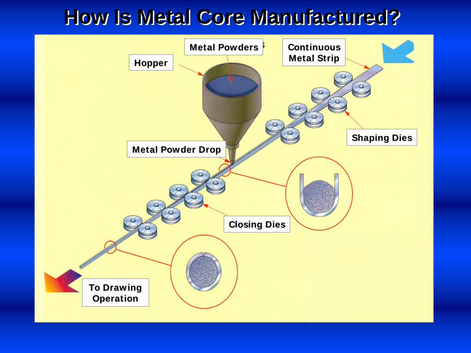
How Is Metal Core Manufactured?How Is Metal Core Manufactured?
To DrawingTo DrawingOperationOperation
Metal Powder DropMetal Powder Drop
HopperHopper
Metal PowdersMetal Powders
Closing DiesClosing Dies
ContinuousContinuousMetal StripMetal Strip
Shaping DiesShaping Dies

WHAT ARE SOME OF THE
MAJOR CHARACTERISTICS
OF METAL CORE?
WHAT ARE SOME OF THE
MAJOR CHARACTERISTICS
OF METAL CORE?

Metal-Cored vs. Solid WireMetal-Cored vs. Solid Wire
Metal-CoredWire Has
HigherCurrentDensity
Metal-Core has greater
ability tobridge gaps
withoutburn
through
Current Path
Metal-Cored Wire Solid Wire

Metal-Cored vs. Solid WireMetal-Cored vs. Solid Wire
Ability to weld thin
materials at high
amperage w/o burn through
Able to use one or two electrode
diameter larger than solid wire
w/o burnthrough
Metal-Cored Wire Solid Wire

Metal-Cored vs. Solid WireMetal-Cored vs. Solid Wire
Spatter is almost non-
existent with high
argon levels
Metal-coredwire has wider
projectionarea giving
excellentside wall
penetration
Metal-Cored Wire Solid Wire

Metal-Cored vs. Solid WireMetal-Cored vs. Solid WireMetal-cored wire
has higher current density, so, with the same
electrode diameters at the same operating
parameters (amperage), metal core
typically has a higher
deposition rate, resulting in
higher travel speeds for the same size weld
Metal-Cored Wire Solid Wire

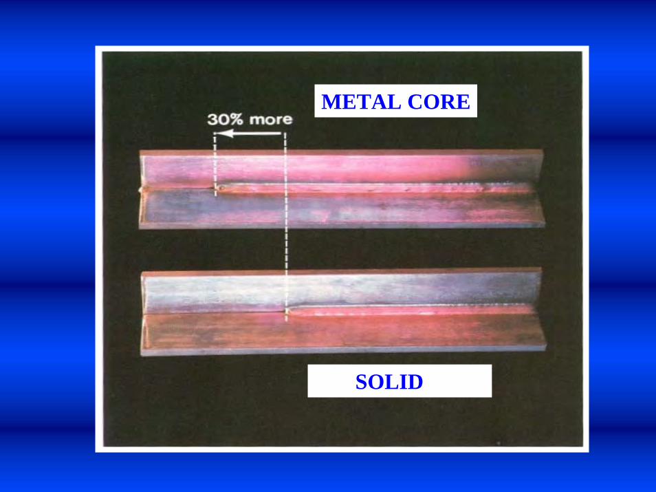
Nugget ProfileCross SectionsNugget ProfileCross Sections
METALCOREWIRE
METALCOREWIRE
SOLIDWIRE
SOLIDWIRE

14.9 Lbs./Hr.Deposition
14.9 Lbs./Hr.Deposition
AMPS
WIRE FEED SPEED
350
566AMPS
WIRE FEED SPEED
460
13.2 Lbs./Hr.Deposition
13.2 Lbs./Hr.Deposition
Higher wire feed speeds for a given arc currentgiving higher deposition rates
Higher wire feed speeds for a given arc currentgiving higher deposition rates
.045” Diameter.045” Diameter
350
METAL COREMETAL CORE SOLID WIRESOLID WIREVS.VS.
SOLID WIRE
METAL CORE

Wire feeders have either two or four drive rolls to help push the wire through the linerProper type of drive is dependent upon the type of wire used :
U-grooved Soft solid wires, eg. Aluminum
V-groovedHard solid wires, eg. Mild steel, stainless steel
V-knurledFlux cored wires, Metal cored wires
Wire feeders have either two or four drive rolls to help push the wire through the linerProper type of drive is dependent upon the type of wire used :
U-grooved Soft solid wires, eg. Aluminum
V-groovedHard solid wires, eg. Mild steel, stainless steel
V-knurledFlux cored wires, Metal cored wires
Wire Feeders / Drive Rolls

Proper size drive rolls are important for good feedingProper pressure on wire is also important for good feeding
Too much pressure deforms the wireToo little pressure cause slippage resulting in erratic feeding and wear spots that can jam in the contact tip
Proper size drive rolls are important for good feedingProper pressure on wire is also important for good feeding
Too much pressure deforms the wireToo little pressure cause slippage resulting in erratic feeding and wear spots that can jam in the contact tip
Wire Feeders / Drive Rolls

The main function of the contact tip is to transfer the electrical energy to the wireContact tips are made of copper for the following reasons :
Good conductivityCan dissipate heat quickly
Unfortunately, copper is a soft metal and the contact tips will wear over timeUse tight tolerance tips for Metal core
Contact Tips

Why is correct contact tip size so important ?
Correct tip sizemaintains electricalcontact at all times
between the contact tip and the welding
wire.
Oversize tips createpotential condition
where arc can initiatebetween the contact tip and the welding
wire.
Welding GunsContact Tips

Metal Core Wire Set-upMetal Core Wire Set-up

Gun angle Wire feed speed VoltageContact Tip to Work Distance (stick-out)Travel speedGas flow rateWhipping
Gun angle Wire feed speed VoltageContact Tip to Work Distance (stick-out)Travel speedGas flow rateWhipping
Setting Welding Variables

15o - 20o15o - 20oRecommended technique :• Lean gun 15o-20o into direction of travelFor Metal Cored Wires –
•Use forward (push) technique
Recommended technique :• Lean gun 15o-20o into direction of travelFor Metal Cored Wires –
•Use forward (push) technique
Direction of Travel for
Metal cored wires
- Forward (push) technique
Direction of Travel for
Metal cored wires
- Forward (push) technique
Welding VariablesGun Angle

Gun angle is also used to control bead appearance and weld qualityAs seen on following slide, gun angle affects bead width, bead profile and penetrationIncorrect gun angle can cause weld defects such as :
Undercut on fillet weldsLack of penetration
Gun angle is also used to control bead appearance and weld qualityAs seen on following slide, gun angle affects bead width, bead profile and penetrationIncorrect gun angle can cause weld defects such as :
Undercut on fillet weldsLack of penetration
Welding VariablesGun Angle

Welding VariablesGun Angle Effect on Penetration
Direction Of WeldingDirection Of Welding
(A) Forehand (Push)Technique
(A) Forehand (Push)Technique
(B) TorchPerpendicular
(B) TorchPerpendicular
(C) Backhand (Drag)Technique
(C) Backhand (Drag)Technique

Wire feed speed (WFS) is generally set at the wire feeder
WFS is proportional to the average amperageAmperage translates to penetration
WFS is also a measure of the deposition rate Units of WFS:
inches per minute (ipm) or meters per minute (m/min)
The correct WFS is generally determined by size of weld bead requiredweld position and thickness of material
Welding VariablesWire Feed Speed

Voltage is generally set at the power sourceVoltage is the force that causes current (amperage) to flowVoltage is also a measure of the heat into the weld Changes in voltage affect :
Arc lengthArc length determines how well the weld puddle will flatten (wet) out
Weld bead widthWeld bead profile
Voltage is generally set at the power sourceVoltage is the force that causes current (amperage) to flowVoltage is also a measure of the heat into the weld Changes in voltage affect :
Arc lengthArc length determines how well the weld puddle will flatten (wet) out
Weld bead widthWeld bead profile
Welding VariablesVoltage
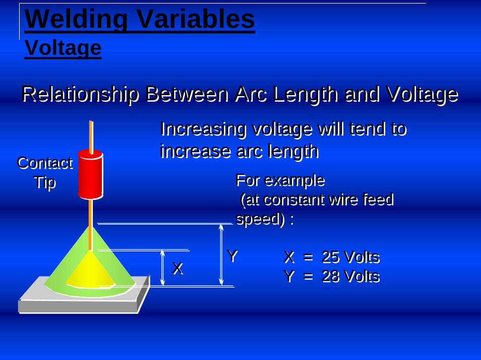
XXYY
ContactTip
ContactTip
Increasing voltage will tend to increase arc lengthIncreasing voltage will tend to increase arc length
For example(at constant wire feed speed) :
X = 25 VoltsY = 28 Volts
For example(at constant wire feed speed) :
X = 25 VoltsY = 28 Volts
Relationship Between Arc Length and VoltageRelationship Between Arc Length and Voltage
Welding VariablesVoltage

XX
YY
Relationship Between Bead Width and VoltageRelationship Between Bead Width and VoltageIncreasing voltage will tend to increase bead widthIncreasing voltage will tend to increase bead width
For example(at constant wire feed speed) :
X = 25 VoltsY = 28 Volts
For example(at constant wire feed speed) :
X = 25 VoltsY = 28 Volts
Bead widthBead width
ContactTip
ContactTip
Welding VariablesVoltage

Welding Variables- Correct Technique – Voltage
-44-
• Smooth consistent arc, minimal spatter, easy to manipulate arc
• Flat bead appearance, smooth transition between weld and base metal
• Good penetration at the root of the weld

Changes in the wire feed speed (WFS) and voltage settings can change the way that molten metal droplets are transfer from the end of the electrode to the weld poolThere are three common modes of metal droplet transfer:
Short circuit transfer modeLower WFS and voltage
Globular transfer modeMedium WFS and voltage
Spray transfer modeHigher WFS and voltage
Droplet Transfer Modes

FeaturesLow Voltage (less than 22 volts)Low AmperageLow Heat InputSpatter is Common
FeaturesLow Voltage (less than 22 volts)Low AmperageLow Heat InputSpatter is Common
Volts
Volts
AmperageAmperage5050 100100 150150 200200 250250 300300 350350
1010
2020
3030
4040 Short
CircuitRegion
ShortCircuitRegion
ApplicationsThin MaterialsOut of Position Welding
ApplicationsThin MaterialsOut of Position Welding
Droplet Transfer ModesShort Circuit Transfer Mode

A B C D E FA B C D E F
WORKWORK
Mechanics of Short Circuit Transfer ModeMechanics of Short Circuit Transfer Mode
Droplet Transfer ModesShort Circuit Transfer Mode

FeaturesMedium Voltage (22 - 26 volts)Medium AmperageLow Heat InputGross Spatter is Common Little Penetration
FeaturesMedium Voltage (22 - 26 volts)Medium AmperageLow Heat InputGross Spatter is Common Little Penetration
Volts
Volts
AmperageAmperage5050 100100 150150 200200 250250 300300 350350
1010
2020
3030
4040Applications
OverlayHardfacing
ApplicationsOverlayHardfacing
GlobularTransferRegion
GlobularTransferRegion
Droplet Transfer ModesGlobular Transfer Mode

FeaturesHigh Voltage (over 26 volts)High AmperageHigh Heat InputNo Spatter is Common Fingernail-like Penetration
FeaturesHigh Voltage (over 26 volts)High AmperageHigh Heat InputNo Spatter is Common Fingernail-like Penetration
Volts
Volts
AmperageAmperage5050 100100 150150 200200 250250 300300 350350
1010
2020
3030
4040
ApplicationsHigh DepositionHigh Production WeldingWelding Thick MaterialsTypically used for flat and
horizontal fillet welding
ApplicationsHigh DepositionHigh Production WeldingWelding Thick MaterialsTypically used for flat and
horizontal fillet welding
SprayTransferRegion
SprayTransferRegion
Droplet Transfer ModesSpray Transfer ModeRecommended Mode for Metal-Core Wire

Gas NozzleGas Nozzle
Contact TipContact Tip
ElectrodeExtensionElectrodeExtension
Base Material
Tip to WorkDistance
Tip to WorkDistance
• The tip to work distance is commonly called stick out
• The tip to work distance is the combination of the electrode extension and the arc length• When welding, the tip to work distance should be kept
relatively constant• Changes in the tip to work distance affect the quality
and appearance of the weld
Welding VariablesContact Tip to Work Distance (stick-out)

1 wire diameter from joint root1 wire diameter from joint root
5/8’ - ¾” Electrode stick-out5/8’ - ¾” Electrode stick-out
Base material
Welding VariablesContact Tip to Work Distance (stick-out)

For a given WFS and voltage setting an optimum travel speed is obtained for different weld sizesIncreases in travel speed will :
Decrease penetrationReduces weld sizeReduces heat input
For a given WFS and voltage setting an optimum travel speed is obtained for different weld sizesIncreases in travel speed will :
Decrease penetrationReduces weld sizeReduces heat input
Welding VariablesTravel Speed

Proper shielding gas flow rate must be maintained to ensure that the molten weld puddle is protected from the atmosphereToo low or too high of a gas flow can have detrimental effects on the weld quality
Too low can cause lack of proper shieldingToo high can cause turbulence which pulls in outside air
Care should be taken to protect the weld area from external draftsCorrect gas and or gas mixtures should be usedCorrect nozzle diameter should be used
Welding VariablesGas Flow Rate
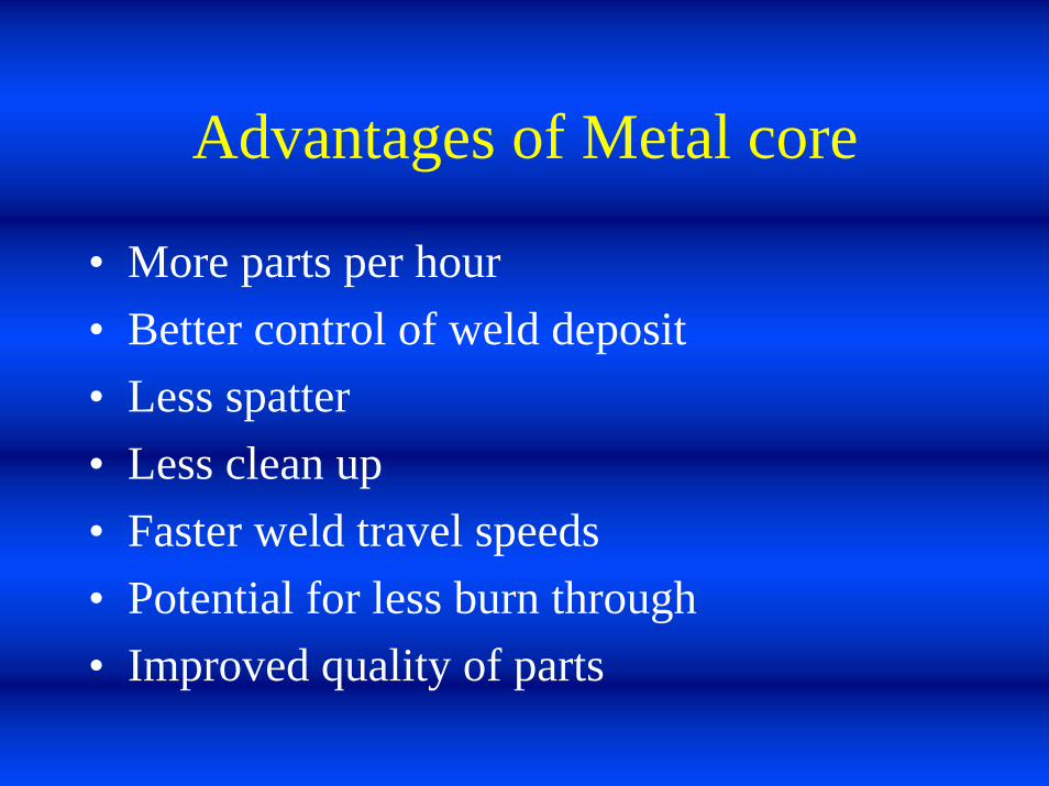
Advantages of Metal core
• More parts per hour• Better control of weld deposit• Less spatter• Less clean up• Faster weld travel speeds• Potential for less burn through• Improved quality of parts

Questions?
• Thank You for Your Time!


