Embed Size (px)
Citation preview

9*
r-»
-1
LL
-0
.'
It)0In
00rt
-1
LL
8
ZL.
Z
CE
LLl
C.
U)C
B
2
1/,
U'b
X
UJ
LL
I
C
CD
crt
HMF**w#P2501 Northchase Pkwy SEWilmington, NC 28405
"HH-SRD" STEEL DOOR
GENERAL NOTES
OUTSWING
'7MPACT"
1. This product has been evaluated and is in compliance with the 5th Edition (2014) Florida BuildingCode (FBC) structural requirements including the "High Velocity Hurricane Zone" (HVHZ).
2. Product anchors shall be as listed and spaced as shown on details. Anchor embedment to basematerial shall be beyond wall dressing or stucco.
3. When used in the "HVHZ" this product complies with Section 1626 of the Florida Building Code anddoes not require an impact resistant covering.
4. When used in areas outside of the "HVHZ" requiring wind borne debris protection this productcomplies with Section 1609.1.2 of the FBC and does not require an impact resistant covering. Thisproduct meets missile level "D" and includes Wind Zone 4 as defined in ASTM E1996 and Section1609.1.2.2 of the FBC.
5. Site conditions that deviate from the details of this drawing require further engineering analysis bya licensed engineer or registered architect.
6. This product meets the water infiltration requirements for the "HVHZ".
7. All steel shall be protected as specified in Section 2222.6 of the FBC.
SHEET#
1
2
3
4
5
6
TABLE OF CONTENTS
DESCRIPTION
Typical elevations, design pressures, & general notesDoor panel detailsHorizontal cross sections
Vertical cross sections
Anchoring detailsBill of materials and components
C)LU
I
LU
LL
LLI
>
0
1
1
X
MAX.
{ OVERA 1 1 aDIMENSION
76.0" X 98.0"
0
g
76" MAX.
OVERALL
FRAME WIDTH
g
X
DESIGN PRESSURE (PSF)
POSITIVE
+47.0
NEGATIVE
-47.0
.........
fs:li g1 5,5 0 *3 0?.3 S *' %.
1..../1 ... +'44 *pTl
I/,illillill
-5gE
i
0
D
0
0
0-
K]
Ld
LL
I
LL
CZ0-0 .
C LU
'll"
B El E* S..
: €43 42 9 9..:Of':P 3 M $ 9de» 5;ME
0 --ZO.00 19 Z
-0 D
i tg ,E:£ d]* 54 -2&
* mil- [1- LL
01
9C.
0
DATE: 8/31/15SCALE: N.T. S.
DWG. BY: JK
CHK. BY: LFS
DRAWING NO.:
FL-18506.4
SHEET 1 of 6
ZJ
mZ0-J
<C
v El
*e
g QS
CL
0
Z
m
69
Z
0
>LIU
IE.
If)
r}
C]
Z
Z
3
U}
Z
0
0
[0
Z
0
J
[D

-0
r.
r'.
-1
LL
9
_J
LL
15ZLU
CE
L.
a_
LL
C
Be
djLL
C
902
a
CDm
I
iIIZ
a_
ih
d
35.75' MAX.
PANEL WIDTH
0
E9
SEE HARDWARE CHART
(D OPAQUE STEEL DOOR PANELSTEEL DOOR SKIN: 18 GA. A60 GALV. (min. 0.047' THK., Fy = 36,800 psi min.)CORE MATERIAL: EPS Foam (Polystyrene - 1.0 PCF Min. Density)
-- 1.66" --
%0
CHANNEL BOTTOM REINFORCEMENTA60 Galv. Steel
L
4
INTERIOR· · ". f ..1 ./-/ , 1 .,...il ..·C. «LI -C_J :
EXTERIOR T \»»-HINGE REINFORCEMENT BAR
(.179" X 1.28" X 9.5")- STEEL SKIN
/»»' HORIZONTAL CROSS SECT/ON
-1.59" -
0.058" - ---
BOX CHANNEL TOP REINFORCEMENTA60 Galv. Steel
MANUFACTURER
SCHLAGE
SCHIAGE
VON DUPRIN
VON DUPRIN
%d
FOAM CORE
HARDWARE CHART
MODEL
LOCK: D-Series
DEADBOLT: D100
NOTE: Panic exit device for use on one active panel only.
L LOCKREINFORCEMENT
BOX
MORTISE LOCK: L9457 w/ Deadbolt
LOCK: 9975 Panic Exit Device w/Mortise Lock (575 Strike Plate)
LOCK: 98NL Panic Exit Device
(499 Sfrike Plate)
. 4.25'
* RIB SnFFENERA60 Galv. Steel
--1
.
ft8-
1-- 0.69"
STEEL SKIN
EXTERIOR
B2
44#A#JA,
tA &
C2
-s«32:M::93.87-
2 *:1 g
E 5< 0 *S 023
INTERIOR
L FOAM CORE8434%14/404
"MAMMM
1 VERTICAL CROSS SECTION2
trL
bD
0
0as
a_
-O 12
Eca. £00 0*
·5 Li. '
E o z3 T
0 CW
8 -50:
iML-
ZEIII
1111"
80/. 10
El <80 : E... qf·2 i o e
.6.099: % 1%@M .r .Z O 00 0
„ 0 19 Z0 N ·:
bm
0
e x21zo O
me9 .(w502&m a. a. IL
DATE: 8/31/15SCALE: N.T. S.
DWG. BY: JK
CHK. BY: LFS
DRAWING NO.:
FL-18506.4
[ZIZ
SHEET 2 OF 6
500
5
0
0Z
W1-
0
03
Z
0
25
in
0
N
0
Z
[1}
3
Ul
Z
00
Z
0-1
3
m
It
0,
3
r-1
3-1
LL
001
acL.
Cl
%
Be0
:2
LL
C.
C.
E
V
g
.P
.
q
(D
ACTIVE
INTERIOR
ir INACTIVE
EXTERIOR
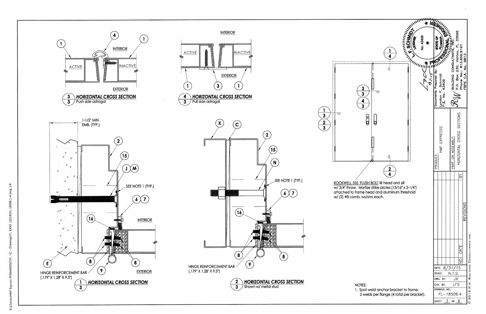
3 HORIZONTAL CROSS SECT/ON
3 Push side astragal
1
g
7
7
17
P V'
HINGE REINFORCEMENT BAR
(.179" X 1.28" X 9.511
3
g
7
I .1
P
7
9
.
F
1-1/2' MIN.
EMB. (TYP.)
2
15
//
8
JM
SEE NOTE 1 (TYP.)
6 7
INTERIOR16
/9 EXTERIOR
HORIZONTAL CROSS SECT/ON
INTERIOR
=ACTIVE _ --- INACTIVE EXTERIOR
S OCD/«4 HORIZONTAL CROSS SECT/ON3) Pull side astragal
-C
HINGE REINFORCEMENT BAR
(.179" X 1.28" X 9.5")
®1
SEE NOTE 1 (TYP.)
6 7
r
16
2
15
8
2 HORIZONTAL CROSS SECTION
3 Shown w/ metal stud
1
3
2
3
V
3
3
4
3
0
V
4
ROCKWELL 555 FLUSH BOLT @ head and sill
w/ 3/4" throw. Mortise strike plates (15/16" x 2-1 /41attached to frame head and aluminum threshold
w/ (2) #8 comb. ws/sms each.
4
2
4
1
4
ff, g= 5<5 3 *S .L:- 4
..... f. 5
.br Pl*P'4„,LI„,
:
NOTES:
1. Spot weld anchor bracket to frame:
2 welds per flange (4 total per bracket).
A.1*
bg00.
0-
'ill"ill
..00 :1,9€v© 5 0 (0 a]
0 .- .Z O CO o
„ OPO Z0 N ·:
0
+
8 k .C 0
2 gz3 0 .
9 C WV A
EXLj
L.L
ZIZ
OC
0
x240 0
542&00 a. 0. LL
DATE: 8/31/15SCALE: N. T. S.
DWG. BY: JK
CHK. BY: LFS
DRAWING NO.:
FL-18506.4
SHEET 3 OF 6
bCO 0
GE0
I
0FI
8
0Z
LU
0
m
Z0
>LJ
Of
Ifl
0
N
0
Z
Z
Z
0
0
[0
Z
0
-1
m

9._J
LL
A
Z
M
L.
./
94-
t
r--4
./
-1
LL
0
0
gj3e
Ln
U'
21LL
I
C(1)
9OS
V
7
7
7
V . V
V
E 7
V .» 7
.ri
14
L-J
tilf)SEE NOTE 1 (TYP.)
EXTERIOR INTERIOR111 lili
1 VERT/CAL CROSS SECT/ON
4 Direct to masonry construction
V
6--1-/----
C Z.
JM
k
EXTERIOR
0-\»
H
NOTES:
1. Spot weld anchor bracket to frame:
2 welds per flange (4 total per bracket).
INTERIOR
Eg
9 9
9g
999 9
V
g
909
2 VERTICAL CROSS SECTION
4 Concrete sill
A
404.:'2 -0.:
S .31 *
L2
bD
0
@
®%6 Eca. .co
8}23
25LL
I
iI,,,k:4
b 90026 7 8: A h # O 0)
1-1 0 0 CO
D >40)0 .r •ZO 00 0
„ 019 Z0 N ·:
B k -
5 (2E.8.8 iw.0 30-
8 8CO CK2 0W0 U
izz:
5 5
DATE: 8/31/15SCALE: N.T. S.
DWG. BY: JK
CHK. BY: LFS
ex 2 1zo ug 4 2 &m a. o. LL
DRAWING NO.:
FL-18506.4
Z0A
SHEET 4 OF 6
W
0
0Z
m
Z
0
(f)
>LU
Of
3
at
If)
0
N
Z
Z
-1
to
Z
0
0
8
Z
0-1
J
[I]

In
-0
'fr.
-1
LL
0
r\1
9-1
LL
Z
Z
<C
I.
CL
E
542Cl
mLJ.
C
CD
9
a-
U(5
Er>0!0.
m
H/NGE JAMB
MASONRY
OPENING
.
.
-
......
-
-
M
HEAD &
JAMBS
(TYP.)
TYP. SILL
H
--- - 8"
Ill
1 li
FRAME ANCHOR/NG
Direct to Masonry
CONCRETE ANCHOR NOTES:
1. Concrete screw locations may be adjusted to maintain a minimum 1"edge distance to mortar joints. ffconcrete screw locations noted as "MAX. O.C." must be adjusted to maintain the minimum edge distanceto mortarjoints. additional concrete screws may be required to ensure the maximum on center dimension isnot exceeded.
2. Concrete anchor table:
ANCHOR
TYPE
CONCRETE
ANCHOR
SCREW
CONCRETE
SLEEVE
ANCHOR
ANCHOR
LOCATION
HEAD / JAMBS
SIU
HEAD / JAMBS
.
ANCHOR
S/ZE
3/8"
1/4"
3/8"
MANUFACTURER
LDT TAPCON® (ITW BUILDEX)
TAPCON® (ITW BUILDEX)ULTRACON® (ELCO)CRETE-FLEX® (ELCO)TAPPER+® (POWERS)
DYNABOLT SLEEVE ANCHOR®
(ITW REDHEAD)
1
1
MIN. EDGE
D/STANCE
3"
2-1/2"
2-1/4"
M/N.
EMBEDMENT
1-1/2"
1-1/4"
1-1/2"
• 14"
-
-
-1
......
torn¥
- 01 0f M
-f
8
THE ENGINEER OR ARCHITECT OF RECORD TO
DETERMINE FRAMING REQUIREMENTS BASED ON
WIND LOADS AND THE CLADDING BEING USED
X
C©-l
.
.
1
11
11
....'ll
1-
-
-
.
H/NGE DETA/L
N
HEAD &
JAMBS
(TYP.)
TYP. SILL
H
--- -8.
111
FRAME ANCHOR/NG
Steel Stud
-14' 1
-
-
-1
-
4,40.....
22:* g
2 0} R Y *S ..5-
..........-
--f
h
- d0
1 . R
h
iD
0
001
0.
'll"</4
C»
.200+[9 6 0
ff¢7 5 5 S E2 > 40
./.. 12 d E d0 19 Z
5 ONY
a. .coe 0*
& 0')
8 LL ·
® C.0
8 iw.0 JO-
ELU06
XLLI
1-L
ZE
0/
0
62
9 5 = 3
542&rn 0. 0- LL
DATE: 8/31/15SCALE: N.T. S.
DWG. BY: JK
CHK. BY: LFS
DRAWING NO.:
F-L-18506.4
CD
Z
GEC)
III0
Z<C
SHEET 5 OF 6
bm
B
E
W
n
0Z
03
Z
0
Di
CY
Ifl
0N
CD
Z
-1
3
m
0
Z
Ul
0
(1]
Z
0
0
ID
rl
UD
0L.
5-1
LL
5
cl
C
E0
X
LLI
LL
C
J
LL
IfZ
C.
U.
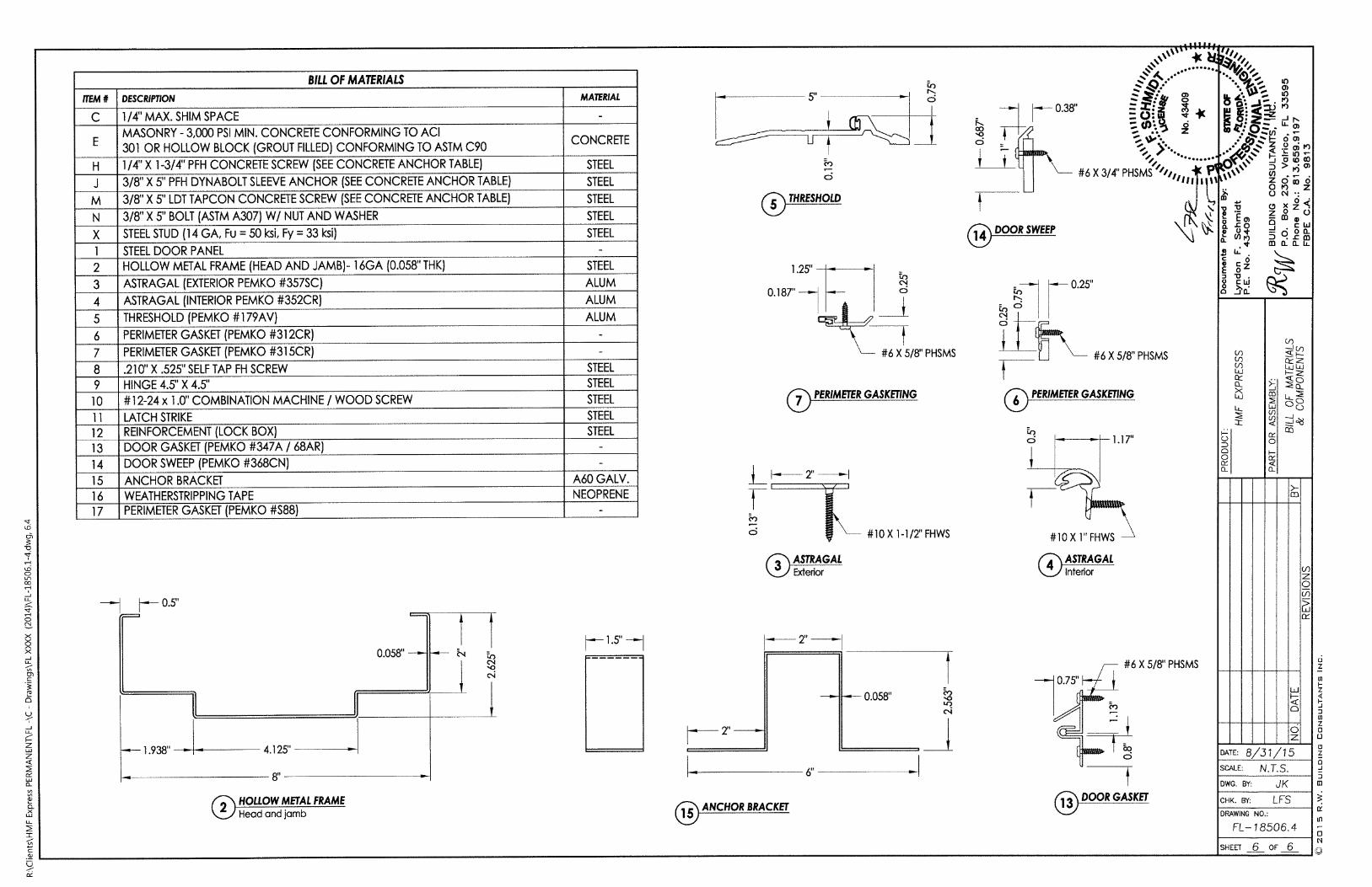
ITEM #
C
E
H
M
N
X
1
2
3
4
5
6
7
8
9
10
11
12
13
14
15
16
17
DESCRIPTION
BILL OF MATER/ALS
1/4' MAX. SHIM SPACE
MASONRY - 3,000 PSI MIN. CONCRETE CONFORMING TO ACI
301 OR HOLLOW BLOCK (GROUT FILLED} CONFORMING TO ASTM C90
1/4" X 1 -3/4" PFH CONCRETE SCREW (SEE CONCRETE ANCHOR TABLE)3/8' X 5" PFH DYNABOLT SLEEVE ANCHOR (SEE CONCRETE ANCHOR TABLE)
3/8'XS'LDT TAPCON CONCRETE SCREW (SEE CONCRETE ANCHOR TABLE)3/8" X 5" BOLT (ASTM A307) W/ NUT AND WASHER
STEEL STUD (14 GA, Fu = 50 ksi, Fy = 33 ksi)STEEL DOOR PANEL
HOLLOW METAL FRAME (HEAD AND JAMB)- 16GA (0.058" THI<)
ASTRAGAL (EXTERIOR PEMKO #357SC)
ASTRAGAL (INTERIOR PEMKO #352CR)
THRESHOLD (PEMKO #179AV)
PERIMETER GASKET (PEMKO #312CR)
PERIMETER GASKET (PEMKO #315CR).210" X .525" SELF TAP FH SCREW
HINGE 4.5" X 4.5"
#12-24 x 1.0" COMBINATION MACHINE / WOOD SCREWLATCH STRIKE
REINFORCEMENT (LOCK BOX)DOOR GASKET (PEMKO #347A / 68AR)DOOR SWEEP (PEMKO #368CN)
ANCHOR BRACKET
WEATHERSTRIPPING TAPE
PERIMETER GASKET (PEMKO #588)
--- 0.5"
-1.938. -
8"
4.125'
HOLLOW METAL FRAMEHead and jamb
L---'
0.058" -
11
1
MATER/AL
CONCRETE
STEEL
ALUM
ALUM
ALUM
STEEL
STEEL
STEEL
STEEL
STEEL
A60 GALV.
NEOPRENE
STEEL
STEEL
STEEL
STEEL
STEEL
--------
eo
-
CS
5"
Ufh
0
/5) THRESHOLD
d
0/)1 5k
1.25" -• .12
0.187 -4 -
-42 -i7- #6 X5/8" PHSMS
/\ PERIMETER GASKETING
2.-1\1
® ASTRAGALExterior
ANCHOR BRACKET
.
#10 X 1 -1/2" FHWS
- 0.058"
LO
CS
--- 0.38'.2
f
14 DOOR SWEEP
"'illifil,0 *83*
:0-44:....f#/ g= 0: 01 **
t.
6 1 ..... .........
#61(314' PHSW'4/Ii P1 Li
lit A
- 0.25"
[_1 - #6 X 5/8" PHSMS
/7\ PERIMETER GASKETING
53U.?C\4
.
#10 Xl"FHWS
® ASTRAGALInterior
1.17"
#6 X 5/8" PHSMS
1-3 DOOR GASKET
E
§0
5D
0
@0-
tillili
if%- m: Zr 2 &
0 JO (0 00D > FS W
'0' 9 cr cs" 019 Z
ON ..
dE gz j
B.*§ 3 S {:e019 J M -cm, * mon- LL
as0-
XLU
LL
I
0
5zv .
DATE: 8/31/15SCALE: N.T. S.
DWG. BY: JK
CHK. BY: LFS
DRAWING NO.:
FL-18506.4
bm
23
9
SHEET 6 OF 6
0/
0
1-Z
U_ 108
03
0Z
m
Z
0
CK
05
L0
0
N
0
Z
Z
J
Z
0
0
0
Z
0-1
J
m


![t~ .5:-8z & = VC) doralpath/2017.5.23.pdf2017/05/23 · 1 2017 Ô5 23 WQbpMN N eHMNjN pDNuv\ t~ .5:-8z_ & = VC) d fuv[g 3+82 = @ t~{z y} Ll X O}@0270)]B Sy} Ll)a_ & t~ .5:-8z_ &=](https://img.dokumen.tips/doc/110x75/5ff4ece97fe9606d0f2a240c/t-5-8z-vc-oralpath2017523pdf-20170523-1-2017-5-23-wqbpmn.jpg)