Embed Size (px)
Citation preview

HLP-C100 Series Operating Manual
HLP-C100 Series
HLP-B Series Operating Manual I
Introduction Thank you for purchasing and using the general-purpose inverter of HLP-C100
series of high quality and high reliability. Please read carefully the operation manual before putting the inverter to use so as
to correctly install and operate the inverter, give full play to its functions and ensure the safety. Please keep the operation manual handy for future reference, maintenance, inspection and repair.
Due to the inverter of a kind of power electronics product it must be installed, tested and adjusted with specialized electrical engineering workers.
The marks of (Danger) ǃ (Caution) and other symbols in the manual remind you of the safety and prevention cautions during the handling, installation, running and inspection. Please follow these instructions to make sure the safe use of the inverter. In case of any doubt please contact our local agent for consultation. Our professional persons are willing and ready to serve you.
The manual is subject to change without notice.
HLP-C100 Series Operating Manual
HLP-C100 Series Operating Manual II
Index
INTRODUCTION.....................................................................................I CHAPTER 1 SAFETY PRECAUTIONS.......................................... - 5 -
1.1 BEFORE POWER-UP .......................................................................- 5 - 1.2 DURING THE POWER-UP ................................................................- 6 - 1.3 DURING THE OPERATION ..............................................................- 6 - 1.4 AFTER THE POWER-OFF ................................................................- 7 -
CHAPTER 2 STANDARDS AND SPECIFICATIONS.................. - 8 - 2.1 LABEL DESCRIPTION ....................................................................- 8 - 2.2 PARTICULAR SPECIFICATIONS ......................................................- 9 - 2.3 TECHNICAL SPECIFICATIONS .......................................................- 9 -
CHAPTER 3 INSTALLATION AND WIRING ............................ - 11 - 3.1 CHECKS BEFORE INSTALLATION .................................................- 11 - 3.2 INSTALLATION DIMENSIONS.......................................................- 12 -
3.2.1 Dimensions of the inverter............................................... - 12 - 3.3 INSTALLATION AND WIRING.......................................................- 12 -
3.3.1 Electrical Installation in General ...................................... - 12 - 3.3.2 Fuse Specifications ........................................................... - 12 - 3.3.3 Installation and Direction.................................................. - 13 - 3.3.4 Wiring terminal................................................................. - 13 - 3.3.5 Wiring.............................................................................. - 15 -
CHAPTER 4 OPERATION AND DISPLAY INTERFACE......... - 16 - 4.1 LCP DIGITAL OPERATOR ...........................................................- 16 - 4.2 QUICK TO SET PARAMETERS .......................................................- 16 -
4.2.1 Preset reference by LCP ................................................... - 16 - 4.2.2 FWD/REV Status............................................................. - 17 - 4.2.3 Data Read-outs.................................................................. - 18 - 4.2.4 View alarm record ............................................................ - 19 - 4.2.5 View state parameter ........................................................ - 20 - 4.2.6 LED Display ..................................................................... - 20 -
CHAPTER 5 QUICK APPLICATION GUIDE ............................. - 21 - 5.1 PARAMETER INITIALIZATION ......................................................- 21 - 5.2 USING LCP TO CONTROL THE DRIVE [HAND]............................ - 21 -

HLP-C100 Series Operating Manual
HLP-C100 Series Operating Manual III
5.3 USING DIGITAL IN TERMINALS TO CONTROL THE DRIVE [AUTO]- 21 - 5.5 MULTI-SPEED .............................................................................- 22 -
CHAPTER 6 PARAMETER OVERVIEW .................................... - 23 - CHAPTER 7 PARAMETER DESCRIPTION ............................... - 30 -
7.1 PARAMETER GROUP 00˖OPERATION/DISPLAY.........................- 30 - 7.2 PARAMETER GROUP 01˖LOAD AND MOTOR.............................- 32 - 7.3 PARAMETER GROUP 02˖BRAKES..............................................- 36 - 7.4 PARAMETER GROUP 03: REFERENCE/RAMPS..............................- 37 - 7.5 PARAMETER GROUP 04: LIMITS/WARNINGS ...............................- 45 - 7.6 PARAMETER GROUP 05: DIGITAL INPUT/OUTPUT.......................- 47 - 7.7 PARAMETER GROUP 06: ANALOG IN/OUT ..................................- 49 - 7.8 PARAMETER GROUP 07: CONTROLLER ......................................- 51 - 7.9 PARAMETER GROUP 08: COMM. AND OPTIONS...........................- 52 - 7.10 PARAMETER GROUP 14: SPECIAL FUNCTIONS ..........................- 54 - 7.11 PARAMETER GROUP 15: DRIVE INFORMATION .........................- 56 - 7.12 PARAMETER GROUP 16: DATA READOUTS ...............................- 58 -
CHAPTER 8 ACCESSORY SPECIFICATION ............................ - 61 - 8.1 BRAKING RESISTOR....................................................................- 61 - NOTE: AN EXTERNAL BRAKING UNIT IS NEEDED WHEN CONNECTING BRAKING RESISTOR FOR THE FC WHICH POWER IS LESS THAN 220V/380V 0.75KW(INCLUDED) .....................................................- 62 -
CHAPTER 9 EMC............................................................................ - 62 - 9.1 EMC–CORRECT INSTALLATION .................................................- 62 - 9.2 RFI SWITCH................................................................................- 62 -
CHAPTER 10 WARNINGS/ALARMS AND FAULT HANDLING....- 62 -
10.1 FAULT LIST ..............................................................................- 63 - 10.2 FAULT INDICATION AND TROUBLE SHOOTING..........................- 65 -
CHAPTER 11 MAINTENANCE..................................................... - 66 - 11.1 NOTE ........................................................................................- 66 - 11.2 STORAGE AND TRANSPORT.......................................................- 66 -
CHAPTER 12 COMMUNICATION PROTOCOL....................... - 67 - 12.1 FORMAT SPECIFICATION ...........................................................- 67 - 12.2 COIL ADDRESSING ....................................................................- 67 -

HLP-C100 Series Operating Manual
HLP-C100 Series Operating Manual IV
12.3 READ COIL STATUS ..................................................................- 69 - 12.4 READ HOLDING REGISTERS......................................................- 70 - 12.4 FORCE SINGLE COIL .................................................................- 71 - 12.5 PRESET SINGLE REGISTER ........................................................- 72 - 12.6 FORCE MULTIPLE COILS...........................................................- 72 - 12.7 PRESET MULTIPLE REGS...........................................................- 74 - 12.8 READ/WRITE ARRAY ................................................................- 74 - 12.9 EXCEPTION CODE......................................................................- 76 -

Chapter 1 Safety Precautions
1.1 Before power-up
Caution
• Check to be sure that the voltage of the main circuit AC power supply matches the input voltage of the inverter.
• Install the inverter in a safe location, avoiding high temperature, direct sunlight, humid air or water.
• The inverter can only be used at the places accredited by our company. Any unauthorized working environment may have the risks of fire, gas explosion, electric shock and other incidents.
• If more than one drive installed on the same control cabinet, make additional cooling fan, so that the inside temperature is lower than 40ćˈin order to prevent overheating or fire occurs.
• It will affect the service life of the inverter if a contactor is installed on the input side to control the start and stop. Generally it is required to control it through terminal commands. Special attention should be paid to its use in the case of the start and stop more frequently places.
• Do not install any switch component like circuit breaker or contactor at the output of the inverter. If any of such components must be installed due process and other needs, it must be ensured that the inverter has no output when the switch acts. In addition, it is forbidden to install any capacitor for improvement of power factor or any varistor against thunder at the output. Otherwise it will cause malfunctions, tripping protection and damages of components of the inverter.
• Please use an independent power supply for the inverter. Do avoid using the common power supply with an electrical welder and other equipment with strong disturbance. Otherwise it will cause the drive to protect or even damage the drive.
• Do not make any high voltage test with any component inside the inverter. These semi-conductor parts are subject to the damage of high voltage.
• The IC board of the inverter are susceptible to the effect and damage of static electricity. Don’t touch the main circuit board.
Danger Misuse may result in casualty.
Caution Indicates misuse may damage the inverter or mechanical system .

HLP-C100 Series Operating Manual
HLP-C100 Series Operating Manual - 6 -
• Installation, commissioning and maintenance must be performed by qualified professional personnel.
• It should be handled with the base to avoid the dropping of the inverter, which may possibly cause the injuries to people and the damages to the inverter.
Danger
• Be sure to turn off the power supply before wiring. • Mount the drive in the metal and other non-combustible materials to avoid the
risk of fire. • Don’t install the drive in a space with explosive gas, otherwiseˈ they lead to
explosion. • R, S, T terminals are power input terminals, never mixed with U.V.W terminals.
Be sure that the wiring of the main circuit is correct. Otherwise it will cause damages of the inverter when the power is applied to it.
• The terminal of must be grounded separately and never connected to N-line. Otherwise it will easily cause the protection or errors of the inverter.
• Do not dissemble or modify any internal connecting cord, wiring or component of the inverter by yourself.
• Never remodel it or exchange control boards and components by yourself. It may expose you to an electrical shock or explosion, etc.
• Keep the inverter from the reach of children or persons not concerned.
1.2 During the power-up
Danger
• Do not plug the connectors of the inverter during the power up to avoid any surge into the main control board due to plugging, which might cause the damage of the inverter.
1.3 During the operation
Caution
• Do not measure the signals on circuit boards while the inverter is running to avoid danger.
• The drive has been optimized before sold. Please make proper adjustments according to the desired functions.
• Do consider the vibration, noise and the speed limit of the motor bearings and the mechanical devices.

HLP-C100 Series Operating Manual
HLP-C100 Series Operating Manual - 7 -
Danger
• Never connect or disconnect the motor set while the inverter is in running. Otherwise it will cause over-current trip and even burn up the main circuit of the inverter.
• Never remove the front cover of the inverter while the inverter is powered up to avoid any injury of electric shock.
• Do not come close to the machine when the Reset Function is used to avoid anything unexpected. The motor may automatically recover from fault.
1.4 After the power-off
Caution Even in the case of the main power, the other voltage inputs and the share load
(linkage of DC intermediate circuit) all have been disconnected from the mains; the internal of the drive may still have residual energy. Before touching any potentially live parts of the inverter, please wait at least 4 minutes. Otherwise, it may expose you to a risk of electrical shock.

HLP-C100 Series Operating Manual
HLP-C100 Series Operating Manual - 8 -
Chapter 2 Standards and Specifications 2.1 Label Description
Significance of the type code:
1-8 HLP-C100 Indicate Product Series 9-12 0D37 Indicate 0.37KW
13-14 21 Indicate 1-Phase AC 220V 23 Indicate 3-Phase AC 220V 43 Indicate 3-Phase AC 380V 15-17 P20 IP rating is 20 18 X Without AC choke A With AC choke 19 X Without Brake unit B With Brake unit 20 X Without DC choke B With DC choke 21 1 Control panel with LED display and potentiometer 22 C With coating on PCB 23 X Reserved
24 0 Domestic sale 1 Overseas sale
25 A Without RS485 B With RS485
26-27 XX Reserved 28-31 VXXX Indicate software version number, such as
V235 means the version number is 2.35 .

HLP-C100 Series Operating Manual
HLP-C100 Series Operating Manual - 9 -
2.2 Particular Specifications
Model Input voltage Input current/A
Output
current/A
Rated powe
r/ KW
Suitable
motor/ KW
Net weight/KG
HLP-C1000D3721 1h200-240V50/60HZ 6.1 2.2 0.37 0.37 0.84 HLP-C1000D7521 1h200-240V50/60HZ 11.6 4.2 0.75 0.75 0.84 HLP-C10001D521 1h200-240V50/60HZ 18.7 6.8 1.5 1.5 0.84 HLP-C1000D3723 3h200-240V50/60HZ 3.5 2.2 0.37 0.37 0.84 HLP-C1000D7523 3h200-240V50/60HZ 6.7 4.2 0.75 0.75 0.84 HLP-C10001D523 3h200-240V50/60HZ 10.9 6.8 1.5 1.5 0.84
3h380-440V50/60HZ 3.5 2.2 HLP-C1000D7543 3h440-480V50/60HZ 3.0 2.1
0.75 0.75 0.84
3h380-440V50/60HZ 5.9 3.7 HLP-C10001D543 3h440-480V50/60HZ 5.1 3.4
1.5 1.5 0.84
3h380-440V50/60HZ 8.5 5.3 HLP-C10002D243 3h440-480V50/60HZ 7.3 4.8
2.2 2.2 0.84
2.3 Technical Specifications Item Specification
Supply voltage single/three phase 200-240 V f20% ; three phase 380-480 V f20%;
Frequency 48-62Hz; Power supply
Max. imbalance 3%; Output voltage three phase 0-100% of supply voltage; Motor
output Output frequency 0-400Hz Control mode V/F Start torque 0.5Hz 150%;
Overload capacity 150% rated output current (60s) PWM switch frequency 2K-16KHz
Speed setting resolution Digital: 0.001Hz; analogy: 0.5‰ of the max. operating frequency ;
Control command source LCP , digital terminal, local bus; Frequency setting source LCP , analog, local bus;
Main control functions
Ramp control Selectable 8-speed steps; Basic
Functions Automatic Voltage Regulation; V/F Control, DC Brake; Speed Limit; Current Limit; Reset Function; Timer; PI Controller.
Application Functions
Speed Open-loop Control; Process Closed-loop Control; Jogging ; Multi-speed Control via Digital input; Deferent speed with deferent ramp; Mechanical Braking; Catch up /Slow down; Relative Scaling Reference; Recover user settings by a key etc.

HLP-C100 Series Operating Manual
HLP-C100 Series Operating Manual - 10 -
Protection Functions
Missing Motor Phase Protection; Low-voltage Protection; Over-voltage Protection; Over-current Protection; Output Phase Loss Protection; Output Short Circuit Protection; Output Grounding Fault Protection; Motor Thermal Protection; CPU Fault; EEPROM Faults; Button freeze; Duplicate Fails; LCP Invalid; LCP Incompatible; Parameter Read-only; Reference Out of Range; Invalid While Running; Password Error etc.
Number 5 digital inputs. Digital input Scanning
time 1ms˗
Number of input
1 analog inputs˄VI˅ˈboth can receive voltage or current signals.
Input accuracy
Max.error: 0.5% of full scale
Resolution 11bit; Analog input
Scanning time 1ms;
Relay output 1 relay outputs˄FA-FB-FC˅; Digital output
Scanning time
1ms;
Power supply +10V 10VDC power supply; Terminal number
1, RS+˄TX+,RX+˅, RS- (TX-, RX-);
Control Terminals
RS485 serial communication Ground for
RS485 COM;
8 segments, 5 numeric displays Display frequency, warnings, status and so on;
Indicator Light FWDǃREVǃHZǃAǃR/MIN display various status of the inverter;
Display
Data read-outs
Frequency setting, output frequency, feedback value, output current, DC link voltage, output voltage, output power, input terminals state, output terminals state, analogue input , 1-10 fault records and accumulated working time etc.;
Remote mounting kit Available when the control panel for external use;
Accessory
Copy card Copy parameters from one inverter to another ;
Environment Enclosure IP20;

HLP-C100 Series Operating Manual
HLP-C100 Series Operating Manual - 11 -
Ambient temperature -10ć-40ć;
Humidity 5%-85%˄95% without condensation˅;
Vibration test 1.14g;
Max. altitude above sea level 1000mˈderating use when more than 1000 meters;
Motor cable length Shield cable: 5 meters, unshield cable: 50 meters;
Attention: Inverter under special environment (derating˅:
• Derating for ambient temperature: If the frequency converter is operated over 40ć ambient temperature, the continuous output current should be decreased. The frequency converter has been designed for operation at max 50ć ambient temperation with one motor size smaller than normal. Continuous operation at full load at 50ć ambient temperation will reduce the lifetime of the frequency converter.
• Derating for low air pressure: The cooling capability of air is decreased at low air pressure. Below 1000m altitude no de-rating is necessary but above 1000m the ambient temperature or the maximum output current should be decreased. Dcrease the output by 1% per 100m altitude above 1000m or reduce the max. ambient temperature by 1 degree per 200m.
Chapter 3 Installation and wiring 3.1 Checks before Installation
The inverter has been strictly and well packed before sold. In consideration of various factors during the transportation special attention should be paid to the following points before installation. If there is anything abnormal please notify the dealer or the relevant people of our company.
• Check if the inverter has got any damage or deformation during the transportation and handling;
• Check if there is one piece of HLP-C100 series inverter and one copy of the quick guide available when unpacking it;
• Check the information on the label to see if the specifications meet your order (Operating voltage and KW value);
• Check if the optional components you ordered are contained; • Check if there is a certificate of qualification and a warranty card.

HLP-C100 Series Operating Manual
HLP-C100 Series Operating Manual - 12 -
3.2 Installation Dimensions 3.2.1 Dimensions of the inverter
Power(kW) and Voltage levels A B C D E F
1×200-240V
3×200-240V
3×380-480V
mm mm mm mm mm mm
0.37-1.5
0.37-1.5
0.75-2.2
74 85 130 140 127 Ф5
3.3 Installation and Wiring 3.3.1 Electrical Installation in General
Caution
All cabling must comply with national and local regulations on cable cross-sections and ambient temperature. Copper conductors required, and ambient temperature(60-75ć) recommended.
Details of terminal tightening torques:
Power˄KW˅and Voltage levels Torque˄Nm˅
1h200-240V
3h200-240V
3h380-480V
Line Motor DC connection/Brake
Control terminals
Relay
0.37-1.5 0.37-1.5 0.75-2.2 1.4 0.8 0.8 0.15-0.4 0.4
3.3.2 Fuse Specifications
Model Fuse size (Rated current/A)
HLP-C1000D3721 10 HLP-C1000D7521 25

HLP-C100 Series Operating Manual
HLP-C100 Series Operating Manual - 13 -
HLP-C10001D521 32 HLP-C1000D3723 10 HLP-C1000D7523 16 HLP-C10001D523 25 HLP-C1000D7543 10 HLP-C10001D543 10 HLP-C10002D243 16
3.3.3 Installation and Direction
Note: Install the unit and make sure that it is free from high moisture ǃ high
temperatureǃheavy dustǃmetal fragments and high oil mist.
3.3.4 Wiring terminal
3.3.4.1 Main Circuit Terminals
Description of main circuit terminals:
Symbol Function
RǃSǃT
Power input: 220V class: 1- phase 200-240V50/60Hz
3- phase 200-240V50/60Hz 380V class: 3- phase 380-480V50/60Hz Single phase connected to RǃT

HLP-C100 Series Operating Manual
HLP-C100 Series Operating Manual - 14 -
UǃVǃW Power output, connect to the motor
-BRǃ+BR Connect the brake resistor, make sure to set C02.10ǃC02.11 etc.
PE Ground terminal
3.3.4.2 I/O Control Terminals
Description of I/O control terminals: Symbol Description Specification
Relay output (FA-FB-FC) Relay output
1ǃResistive load: 250VAC 3A/30VDC 3A; 2ǃInductive load: 250VAC 0.2A/24VDC 0.1A˄cos¶=0.4˅; 3ǃFA FB normally closed, FB FC normally open;
Digital input (FORǃREVǃ
DI1ǃDI2ǃDI3)
Digital control terminals
1ǃLogic: >DC19V logic ‘0’; <DC14V logic ‘1’; 2ǃVoltage: DC 0-24V;
GND Digital or Analog ground Isolated from internal COM;
+10V 10V power supply Max.load 25 mAˈwith over load and short circuit protection functions;
Analog input (VI˅
Analog setting/Feedback
Set by the related parameter, analog input channel can be configurated to 0-20mA or 0-10V : Voltage input: 1ǃInput impedance: about 10 KΩ; 2ǃMaximum withstand voltage is 20V ˈduration of 2 seconds, the maximum reverse voltage is -15V ˈduration of 2seconds. Current input: 1ǃInput impedenceİ500Ω; 2ǃMaximum withstand current is 29 mA duration of 2 seconds.
RS+, RS- RS485 communication RS485 + and RS485- ;
COM Ground for communication Isolated from internal GND;
Note: Only the machine with RS485 (type code number 25 is B) has RS+ RS- and COM;
3.3.4.3 Communication bus switch and external lcp interface

HLP-C100 Series Operating Manual
HLP-C100 Series Operating Manual - 15 -
3.3.5 Wiring Basic Connection Diagram of HLP-C100 series inverter:
R
S
T
E
+10VVI
GND
FORREV
DI1
DI2DI3
0RWRU
U
V
W
PE
FA
FB
FC
+BR
-BR%UDNH
5HVLVWRU
5HOD\2XWSXW
3RZHULQSXW
9'&P$
RS+
RS-
COM
56&RPPXQLFDWLRQ
6KLHOGHGZLUH
Precautions for the main circuit wiring:
• While wiring the sizes and specifications of wires should be selected and the wiring should be executed according to the electrical engineering regulations to ensure the safety.
• It is better to use shielded wire or wire conduit for power cord and ground the shielded layer or two ends of wire conduit.
• Be sure to install a circuit Breaker between the power supply and the input terminals (R.S.T). (If using RCD, please choose B type)
• Phase-shifting capacitors, LC, RC noise filters etc, can never be connected to the output terminals of the inverter.
• Please lower the inverter switching frequency when there is a longer distance between the inverter and the motor.
• Drive earth leakage current is greater more than 3.5 mA. According to the requirments of IEC 61800-5-1 , must use the following ways to enhance the protection of ground: minimum 10mm2 cross sectional area of copper, or additional PE line, its cross sectional area and the main power cable should be the same, must be separate grounded.

HLP-C100 Series Operating Manual
HLP-C100 Series Operating Manual - 16 -
• Make sure reliable ground of the inverter in accordance with IEC 61800-5-1.
• Please refer to 9.2 for the use of RFI SWITCH.
Chapter 4 Operation and Display Interface 4.1 LCP Digital Operator
4.2 Quick to set parameters 4.2.1 Preset reference by LCP Example: Set a reference to10.25 That is C03.10 [0] =20.5:
Key-press LCP Display Action Description
C00.04 Press key to display the first
basic C00.03
C03.00 Turn clockwise to select
parameter group C03
C03.00
Press key to shift to fractional part
C03.10 Turn clockwise to select
parameter C03.10

HLP-C100 Series Operating Manual
HLP-C100 Series Operating Manual - 17 -
[0] Press to show the first option of
C03.10
0000 Press to show the value of the
first option of parameter C03.10
000.5 Turn clockwise to change the
fractional part to 5
000.5
Press key to shift to integral part
020.5 Turn clockwise to change the
integral part to 20
END Press to accept the change and
save it as 20.5
4.2.2 FWD/REV Status Confirm the direction of the motor according to the set value, as shown in the
following table: Reference: Running status Indicator Display
ı0 STOP
˘0 STOP FWD REV
ı0 FWD
ı0 REV
˘0 FWD
˘0 REV

HLP-C100 Series Operating Manual
HLP-C100 Series Operating Manual - 18 -
Note: A flash light denotes the status coming, Light on indicates the current state, and light off means not in this state. Example 1: The first line of the table indicates the drive is stop and the reference
is greater than or equal to 0, means the dirve at some time in the future will run forward.
Example 2: The fourth line of the table represents the current drive is reverse running, and the reference setting is greater than or equal to 0, it means the drive at some time in the future will run forward.
4.2.3 Data Read-outs
Display Items
Key-press LCP Display Action Description
Output Frequency
Initial interface
Show the output frequency (C16.13) is 50.0Hz, display
accuracy : 0.1
Reference˄%˅
Show the preset reference ( C16.01) is 50%, display
accuracy: 0.001
Motor Current
Show the motor current (C16.14) is 9.00A, display
accuracy: 0.01
Motor Voltage
Show the motor voltage (C16.12) is 380.0V, display
accuracy: 0.1
Motor Speed
Show the motor speed (C16.05) is 1440rpm, display
accuracy:1
DC Voltage
Show the DC voltage(C16.30) is 540.0V,
display accuracy: 0.1
Inverter temperatu
re
Show the inverter temperature (parC16.34) is
45ć, display accuracy:1

HLP-C100 Series Operating Manual
HLP-C100 Series Operating Manual - 19 -
Feedback Value
Show the feedback value(C16.52) is 28.000, display accuracy: 0.001
Analog in VI
Show analog in VI (C16.62) is 10.00V, display accuracy:
0.01
Note: Press key to change the display items on control panel, however, C00.33 must be activated (see C00.33).
4.2.4 View alarm record If the drive trips, fault code will be showed to illustrate the reason, all the trip
record will be saved.
Key-press LCP Display Action Description
C00.04 Press key to display the first basic
C00.03.
C15.00 Turn clockwise to select par. group
No. C15.
C15.00
Press to select parameter number.
C15.30
Turn clockwise to select C15.30
[0]
Press to show the first option of C15.30
**
Press to show the first fault record.
[1] Press to show the second fault record, it
can display up to ten recent fault records in turn.
HLP-C100 Series Operating Manual
HLP-C100 Series Operating Manual - 20 -
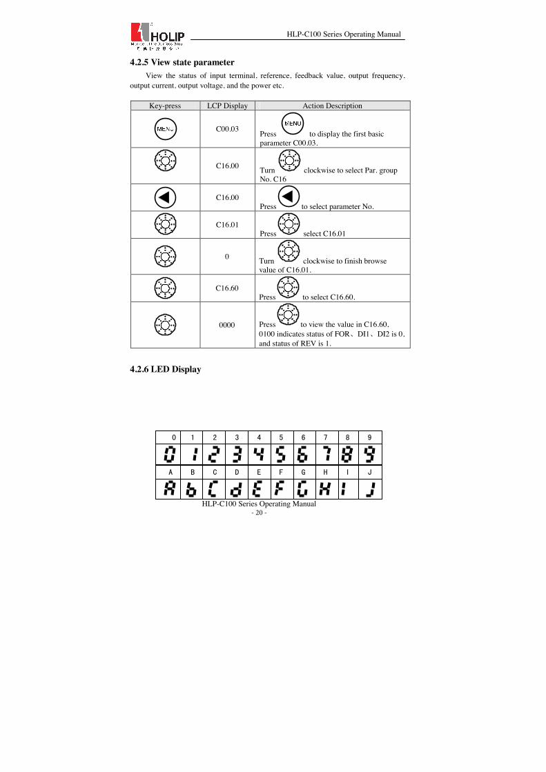
4.2.5 View state parameter View the status of input terminal, reference, feedback value, output frequency,
output current, output voltage, and the power etc.
Key-press LCP Display Action Description
C00.03 Press to display the first basic
parameter C00.03.
C16.00 Turn clockwise to select Par. group No. C16
C16.00
Press to select parameter No.
C16.01
Press select C16.01
0 Turn clockwise to finish browse
value of C16.01.
C16.60
Press to select C16.60.
0000 Press to view the value in C16.60,
0100 indicates status of FORǃDI1ǃDI2 is 0, and status of REV is 1.
4.2.6 LED Display
$ % ( *& + ,' ) -

HLP-C100 Series Operating Manual
HLP-C100 Series Operating Manual - 21 -
Chapter 5 Quick Application Guide 5.1 Parameter initialization 1.Set C14.22 = 2 2.Cut off the main power and Re-power on, LCP displays E.80 3.Press “OFF” key on LCP.
5.2 Using LCP to control the drive [HAND] 1.Parameter initialization˗ 2.Press “HAND” key on LCP; 3. Turn the incremental potentiometer to adjust the frequency; 4.PressĀOFFākey on LCP to stop the frequency converter;
5.3 Using digital in terminals to control the drive [AUTO]
1. Parameter initialization; 2. Press “AUTO” key on LCP (Digital control and communication control are only active in auto mode); 3. Frequency source˖Preset C03.10 or select frequency source by C03.15ǃC03.16; 4. Connect digital input terminal FOR and GND to operate the frequency convert; 5. Disconnect the digital input terminal FOR and GND to stop the frequency converter.
. / 2 40 5 61 3 7
8 9 < : ; =
D E H JF K LG I M
N O R TP U VQ S W
X Y \
Z
[ ]
HLP-C100 Series Operating Manual
HLP-C100 Series Operating Manual - 22 -
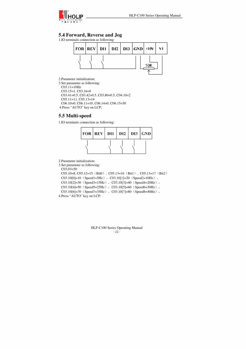
5.4 Forward, Reverse and Jog 1.IO terminals connection as following:
2.Parameter initialization; 3.Set parameter as following: C03.11=10Hz C03.15=1, C03.16=0 C03.41=0.5, C03.42=0.5, C03.80=0.5, C04.10=2 C05.11=11, C05.13=14 C06.10=0, C06.11=10, C06.14=0, C06.15=50 4.Press “AUTO” key on LCP;
5.5 Multi-speed 1.IO terminals connection as following:
2.Parameter initialization; 3.Set parameter as following: C03.03=50 C05.10=8, C05.12=15˄Bit0˅, C05.13=16˄Bit1˅, C05.13=17˄Bit2˅ C03.10[0]=10˄Speed1=5Hz˅ˈC03.10[1]=20˄Speed2=10Hz˅ˈ C03.10[2]=30˄Speed3=15Hz˅ˈC03.10[3]=40˄Speed4=20Hz˅ˈ C03.10[4]=50˄Speed5=25Hz˅ˈC03.10[5]=60˄Speed6=30Hz˅ˈ C03.10[6]=70˄Speed7=35Hz˅ˈC03.10[7]=80˄Speed8=40Hz˅ˈ 4.Press “AUTO” key on LCP;

HLP-C100 Series Operating Manual
HLP-C100 Series Operating Manual - 23 -
Chapter 6 Parameter Overview Item Parameter
No. Function Description Setting range Unit Default setting
Page No.
C00.04 Operating State at Power-up
0˖Resume˗ 1˖Forced stop reference=old˗ 2˖Forced stop reference=0˗
1
C00.33 LCP Display Option 0-2047 0 C00.40 HAND key on LCP 0˖Disabled ˗1˖Enabled˗ 1
C00.41 OFF key on LCP 0˖Disable All˗ 1˖Enable All˗ 2˖Enable Reset Only˗
1
C00.42 AUTO key on LCP 0˖Disabled˗ 1˖Enabled˗ 1
Parameter
Group 00:
Operation /
Display
C00.60 Menu Password 0˖Disabled 1˖Enabled˗ 0
C01.00 Configuration Mode 0˖Speed open loop ˗ 1˖Speed closed loop˗ 3˖Process closed loop˗
0
*C01.20 Motor Power [kW][HP] Dep.on motor date kW *
*C01.22 Motor Voltage˄Um.n˅ 50~1000 V *
*C01.23 Motor Frequency˄fm.n˅ 20~400 Hz *
*C01.24 Motor Current˄Im.n˅ Dep.on motor date A *
*C01.25 Motor Nominal Speed˄nm.n˅ 100~9999 rpm *
*C01.42 Motor Cable Length 0~150 m 50 C01.55 U/F Characteristic-U 0~999 V C01.56 U/F Characteristic-F 0~400 Hz C01.71 Start Delay 0.0~10.0 s 0.0
C01.72 Start Function 0˖DC hold/delay time˗ 2˖Coast/Delay time˗ 2
*C01.73 Flying start 0˖Disabled˗ 1˖Enabled˗ 0
C01.80 Function at Stop 0˖Coast; 1˖DC Hold˗ 0
Parameter
Group01˖
Load /
motor
C01.82 Min Speed for Function at Stop 0.0~20.0 Hz 0.0

HLP-C100 Series Operating Manual
HLP-C100 Series Operating Manual - 24 -
[Hz] C02.00 DC Hold Current 0~150 % 50 C02.01 DC Brake Current 0~150 % 50 C02.02 DC Braking Time 0.0~60.0 s 10.0
C02.04 DC Brake Cut In Frequency 0.0~400.0 Hz 0.0
C02.10 Brake Function 0˖Off˗ 1˖Resistor brake˗ 2˖AC brake˗
0
C02.11 Brake Resistor (ohm) Dep.on motor date Ω *
Parameter
Group 02:
Brake Functio
n
C02.17 Over-voltage Control
0˖Disabled˗ 2˖Enabled˗ 0
C03.03 Maximum Reference 0.000~4999.000 50.000 C03.10 Preset Reference -100.00~100.00 % 0.00 C03.11 Jog Speed [Hz] 0.0~400.0 Hz 5.0
C03.12 Catch up/slow Down Value 0.00~100.00 % 0.00
C03.15 Reference Resource 1 1
C03.16 Reference Resource 2 2
C03.18 Relative Scaling Reference Resource
0˖No function˗ 1˖Analog input VI ˗ 11˖Local bus ref˗ 21˖LCP potentiometer˗ 0
C03.40 Ramp 1 Type 0˖Linear˗ 2˖Sine ramp˗ 0
C03.41 Ramp 1 Ramp up Time 0.10~300.00 s *
C03.42 Ramp 1 Ramp Down Time 0.10~300.00 s *
C03.50 Ramp 2 Type 0˖Linear˗ 2˖Sine ramp˗ 0
C03.51 Ramp 2 Ramp up Time 0.10~300.00 s *
C03.52 Ramp 2 Ramp down Time 0.10~300.00 s *
C03.60 Ramp 3 Type 0˖Linear˗ 2˖Sine ramp˗ 0
C03.61 Ramp 3 Ramp up Time 0.05~3600.00 s *
C03.62 Ramp 3 Ramp down Time 0.05~3600.00 s *
C03.70 Ramp 4 Type 0˖Linear˗ 2˖Sine ramp˗ 0
Parameter
Group 03:
Reference
/
Ramps
C03.71 Ramp 4 Ramp up Time 0.10~300.00 s *

HLP-C100 Series Operating Manual
HLP-C100 Series Operating Manual - 25 -
C03.72 Ramp 4 Ramp down Time 0.10~300.00 s *
C03.80 Jog Ramp Time 0.10~300.00 s *
C03.84 Ramp 5 Type 0˖Linear˗ 2˖Sine ramp˗ 0
C03.85 Ramp 5 Ramp up Time 0.10~300.00 s *
C03.86 Ramp 5 Ramp down Time 0.10~300.00 s *
C03.87 Ramp 6 Type 0˖Linear˗ 2˖Sine ramp˗ 0
C03.88 Ramp 6 Ramp up Time 0.10~300.00 s *
C03.89 Ramp 6 Ramp down Time 0.10~300.00 s *
C03.90 Ramp 7 Type 0˖Linear˗ 2˖Sine ramp˗ 0
C03.91 Ramp 7 Ramp up Time 0.10~300.00 s *
C03.92 Ramp 7 Ramp down Time 0.10~300.00 s *
C03.93 Ramp 8 Type 0˖Linear˗ 2˖Sine ramp˗ 0
C03.94 Ramp 8 Ramp up Time 0.10~300.00 s *
C03.95 Ramp 8 Ramp down Time 0.10~300.00 s *
C03.96 Link preset
reference and ramp time
0: No link; 1: Link 0
*C04.10 Motor Speed Direction
0˖Clockwise˗ 1˖Counterclockwise˗ 2˖Both˗
2
*C04.12 Motor Speed Low Limit [Hz] 0.0~400.0 Hz 0.0
*C04.14 Motor Speed High Limit [Hz] 0.0~400.0 Hz 65.0
C04.18 Current Limit 0~300 % 150
*C04.19 Max. Output Frenquency 0.0~400.0 Hz 65.0
C04.52 Warning Speed Low 0.0~400.0 Hz 0.0
C04.53 Warning Speed High 0.1~400.0 Hz 65.0
Parameter
Group 04:
Limits /
Warnings *C04.58 Missing Motor 0˖Off ˗ 1˖On˗ 1

HLP-C100 Series Operating Manual
HLP-C100 Series Operating Manual - 26 -
Phase Function
C04.61 Bypass Speed From [Hz] 0.0~400.0 Hz 0.0
C04.63 Bypass Speed To [HZ] 0.0~400.0 Hz 0.0
C05.10 Terminal FOR Digital Input 8
C05.11 Terminal REV Digital Input 10
C05.12 Terminal DI1 Dgital Input 15
C05.13 Terminal DI2 Digital Input 16
C05.14 Terminal DI3 Digital Input
0˖No operation˗ 1˖Reset˗ 2˖Coast inverse˗ 5˖DC-brake inverse˗ 6˖Stop inverse˗ 8˖Start˗ 10˖Reversing˗ 11˖Start reversing˗ 14˖Jog˗ 15˖Preset ref bit0˗ 16˖Preset ref bit1˗ 17˖Preset ref bit2˗ 28˖Catch up˗ 29˖Slow down˗ 34˖Ramp bit0˗ 35˖Ramp bit1˗ 36˖Ramp bit2˗
17 Paramet
er Group
05: Digital In/Out\
C05.40 Relay Function˄FA-FBǃFB-
FC˅
0˖No operation˗ 5˖Drive running˗ 9˖Alarm˗ 10˖Alarm or Warning˗ 15˖Out of frequency rang˗16˖Below frequency, low˗
17˖ Above frequency, high˗ 21˖Thermal warning˗ 24˖Ready, voltage ok˗25˖Reverse˗ 26˖Bus ok˗ 28˖Brake, no brake warning˗ 53˖No alarm˗ 55˖Running reverse˗
0
C06.10 Terminal VI Low Voltage 0.00~9.99 V 0.07
C06.11 Terminal VI High Voltage 0.10~10.00 V 10.00
C06.12 Terminal VI Low Current 0.00~19.99 mA 0.14

HLP-C100 Series Operating Manual
HLP-C100 Series Operating Manual - 27 -
C06.13 Terminal VI High current 0.01~20.00 mA 20.00
C06.14 Terminal VI Low Ref./Feedb.Value -4999.000~4999.000 0.000
C06.15 Terminal VI High Ref./Feedb.Value -4999.000~4999.000 50.000
C06.16 Terminal VI Filter Time Contant 0.01~10.00 s 0.01
C06.18 Terminal VI Zero dead band 0.00~20.00 V/m
A 0.00
C06.19 Terminal VI Mode 0˖Votage mode˗ 1˖Current mode˗ 0
C06.81 LCP Potmeter Low Ref. -4999.000~4999.000 0.000
Parameter Group 06: Analog In/Out
C06.82 LCP Potmeter High Ref. -4999.000~4999.000 50.000
C07.20 Process CL Feedback Resource
0˖No Function˗ 1˖Analog in VI˗ 11˖Local bus˗
0
C07.31 Process PI Anti Windup
0˖Disabled˗ 1˖Enabled˗ 1
C07.33 Process PI Proportional Gain 0.0~10.00 0.01
C07.34 Process PI Integral time 0.10~9999.00 s 9999.00
C07.38 Process PI Feed Forward Factor 0~400 % 0
C07.39 On Reference Bandwidth 0~200 % 5
C07.41 Process PI Output Low -100-100 % 0
Parameter
Group07: PID Control
C07.42 Process PI Output High -100-100 % 100
C08.01 Control Site 0˖Digital and ctrl.word ˗ 1˖Digital only˗ 2˖Control Word only˗
0
C08.02 Control Word Source 0˖None ˗ 1˖FC RS485˗ 1
C08.03 Control Word Timeout Time 0.1~6500.0 s 1.0
Parameter
Group 08: FC
Port Settings C08.04 Control Word
Timeout Function
0˖Off˗ 1˖Freeze output˗ 2˖Stop˗ 3˖Jogging ˗ 4˖Max. speed˗ 5˖Stop and trip˗
0
HLP-C100 Series Operating Manual
HLP-C100 Series Operating Manual - 28 -
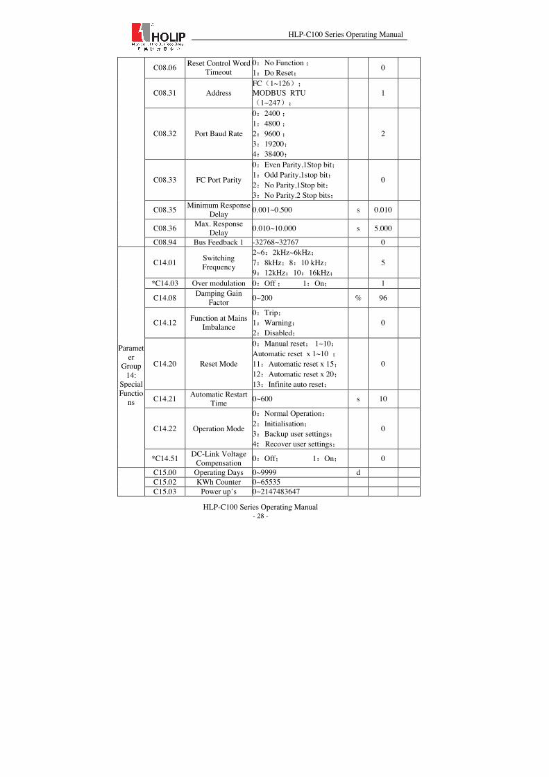
C08.06 Reset Control Word Timeout
0˖No Function ˗ 1˖Do Reset˗ 0
C08.31 Address FC˄1~126˅˗ MODBUS RTU˄1~247˅˗
1
C08.32 Port Baud Rate
0˖2400 ˗ 1˖4800 ˗ 2˖9600 ˗ 3˖19200˗ 4˖38400˗
2
C08.33 FC Port Parity
0˖Even Parity,1Stop bit˗ 1˖Odd Parity,1stop bit˗ 2˖No Parity,1Stop bit˗ 3˖No Parity,2 Stop bits˗
0
C08.35 Minimum Response Delay 0.001~0.500 s 0.010
C08.36 Max. Response Delay 0.010~10.000 s 5.000
C08.94 Bus Feedback 1 -32768~32767 0
C14.01 Switching Frequency
2~6˖2kHz~6kHz˗ 7˖8kHz˗8˖10 kHz˗ 9˖12kHz˗10˖16kHz˗
5
*C14.03 Over modulation 0˖Off ˗ 1˖On˗ 1
C14.08 Damping Gain Factor 0~200 % 96
C14.12 Function at Mains Imbalance
0˖Trip˗ 1˖Warning˗ 2˖Disabled˗
0
C14.20 Reset Mode
0˖Manual reset˗ 1~10˖Automatic reset x 1~10 ˗11˖Automatic reset x 15˗12˖Automatic reset x 20˗13˖Infinite auto reset˗
0
C14.21 Automatic Restart Time 0~600 s 10
C14.22 Operation Mode
0˖Normal Operation˗ 2˖Initialisation˗ 3˖Backup user settings˗ 4: Recover user settings˗
0
Parameter
Group 14:
Special Functio
ns
*C14.51 DC-Link Voltage Compensation 0˖Off˗ 1˖On˗ 0
C15.00 Operating Days 0~9999 d C15.02 KWh Counter 0~65535
C15.03 Power up’s 0~2147483647

HLP-C100 Series Operating Manual
HLP-C100 Series Operating Manual - 29 -
C15.06 Reset KWh Counter 0˖Do not reset ˗ 1˖Reset Counter˗
C15.30 Fault Log: Error Code 0~255
C15.31 Internal Fault Reason -32767~32767
C15.40 FC Type View FC type C15.41 Power Section View power size of the drive
C15.42 Voltage View Mains Voltage of the drive
C15.43 Software Version View the software version
C15.44 Ordered Type Code View the ordered type code of the drive
C15.46 Frequency converter ordering NO.
View frequency converter ordering NO.
C15.47 Power Card Ordering NO.
View power card ordering No. of the drive
C15.48 LCP ID NO. View LCP ID NO.
C15.49 Software ID Control Card
View software ID control card
C15.50 Software ID Power Card View software ID Power card
C15.51 Frequency Converter Serial Number View frequency converter No.
C15.53 Power Card Serial number
View power card serial number
Parameter
Group 15:
Drive Informa
tion
C15.92 Parameter List View parameter list of the drive
C16.00 Control Word 0~65535 C16.01 Reference [Unit] -4999.000~4999.000 C16.05 Motor Speed [RPM] 0~9999 Hz C16.10 Power[KW] 0.000~1000.000 kW C16.12 Motor Voltage 0.0~65535 V C16.13 Frequency 0.0~400.0 Hz C16.14 Motor Current 0.00~655.35 A C16.30 DC Link Voltage 0~65535 V C16.34 Heat sink Temp. 0~255 ć C16.52 Feedback # [Unit] -4999.000~4999.000 C16.60 Digital Input 0~65535
C16.62 Analog Input VI 0.000-20.000 V/ mA
C16.71 Relay Output [bin] 0~65535 C16.86 FC Port REF -32768~32767 C16.90 Alarm Word 0~0xFFFFFFFFUL C16.91 Alarm Word 2 0~0xFFFFFFFFUL C16.92 Warning Word 0~0x7FFFFFFFUL
Parameter
Group 16:
Data Readout
s
C16.93 Warning Word 2 0~0x7FFFFFFFUL

HLP-C100 Series Operating Manual
HLP-C100 Series Operating Manual - 30 -
Note: Reference signed with Ā*āin parameter No. column means this parameter can’t be modified when the motor is running. In factory setting column, “*” means the default setting for this parameter is determined by the drive type.
Chapter 7 Parameter Description
7.1 Parameter Group 00˖Operation/Display C00.0* Basic Settings
C00.04 Functon Description
Range Unit Default Setting

HLP-C100 Series Operating Manual
HLP-C100 Series Operating Manual - 31 -
Option: [0] Resume, local reference is stored and used after power up; [1] Forced stop, ref=old, local reference is stored and used after power up; [2] Forced stop, ref=0, local reference is set to 0;
Function: This parameter is used to control whether or not the frequency converter should automatic running the motor when powering up after a power down in Hand mode.
Description of choice: When select Ā[0]ā, frequency converter starts in same Hand mode roof state as when powered off; When select Ā [1] ā , frequency converter powers up in off state meaning that motor is stopped after power up; When selectĀ[2]ā, frequency converter powers up in off state meaning that motor is stopped after power up. Local reference is set to 0. Thus motor will not start running before local reference has been increased.
C00.3*LCP Readout
Description of the choice: LCP will be fixed to display the output frequencyǃreference and motor current. This parameter is used to show 11 basic operating states of the inverter, each parameter corresponds to a binary code: “1” means display the item, “0” means does not display the item. For example, if you want to display the states of the temperature and the terminal VI on LCP. Transform the binary code to decimal digit, C00.33=1h23+1h24=24.
Reserved
Reserved
Reserved
Reserved
Reserved
Reserved
VI Input
Temperature
DC-voltage
Motor Speed
Motor V
oltage
0 0 0 0 0 0 1 1 0 0 0
C00.4* LCP Keypad
Option: [0] Disabled: Hand key has no function; [1] Enabled: Hand key is functional;
Description of the choice: The frequency converter can operate in the following three mode: HANDǃOFF and AUTO. When running in Hand mode, the frequency
Operaton State at Power-up(Hand) 0~2 1
0~9999.00 C00.33 Function Description
Range Unit Default setting LCP Display Option 0~2047 0
C00.40 Function Description 1
Range Unit Default setting HAND Key on LCP 0~1
HLP-C100 Series Operating Manual
HLP-C100 Series Operating Manual - 32 -
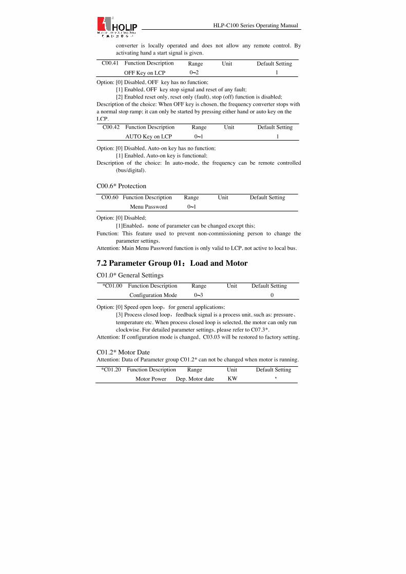
converter is locally operated and does not allow any remote control. By activating hand a start signal is given.
Option: [0] Disabled, OFF key has no function; [1] Enabled, OFF key stop signal and reset of any fault; [2] Enabled reset only, reset only (fault), stop (off) function is disabled;
Description of the choice: When OFF key is chosen, the frequency converter stops with a normal stop ramp; it can only be started by pressing either hand or auto key on the LCP.
Option: [0] Disabled, Auto-on key has no function;
[1] Enabled, Auto-on key is functional; Description of the choice: In auto-mode, the frequency can be remote controlled
(bus/digital). C00.6* Protection Option: [0] Disabled;
[1]Enabledˈnone of parameter can be changed except this; Function: This feature used to prevent non-commissioning person to change the
parameter settings. Attention: Main Menu Password function is only valid to LCP, not active to local bus.
7.2 Parameter Group 01˖Load and Motor C01.0* General Settings
Option: [0] Speed open loopˈfor general applications; [3] Process closed loopˈfeedback signal is a process unit, such as: pressureǃtemperature etc. When process closed loop is selected, the motor can only run clockwise. For detailed parameter settings, please refer to C07.3*.
Attention: If configuration mode is changed, C03.03 will be restored to factory setting. C01.2* Motor Date Attention: Data of Parameter group C01.2* can not be changed when motor is running.
C00.41 Function Description OFF Key on LCP 0~2
Range Unit Default Setting 1
C00.42 Function Description
Range Unit Default Setting AUTO Key on LCP 0~1 1
*C01.00 Function Description
Range Unit Default Setting Configuration Mode 0~3 0
0
C00.60 Function Description
Range Unit Default Setting Menu Password 0~1
*C01.20 Function Description
Range Unit Default Setting Motor Power Dep. Motor date KW *
C00.42 Function Description
Range Unit Default Setting AUTO Key on LCP 0~1 1
HLP-C100 Series Operating Manual
HLP-C100 Series Operating Manual - 33 -
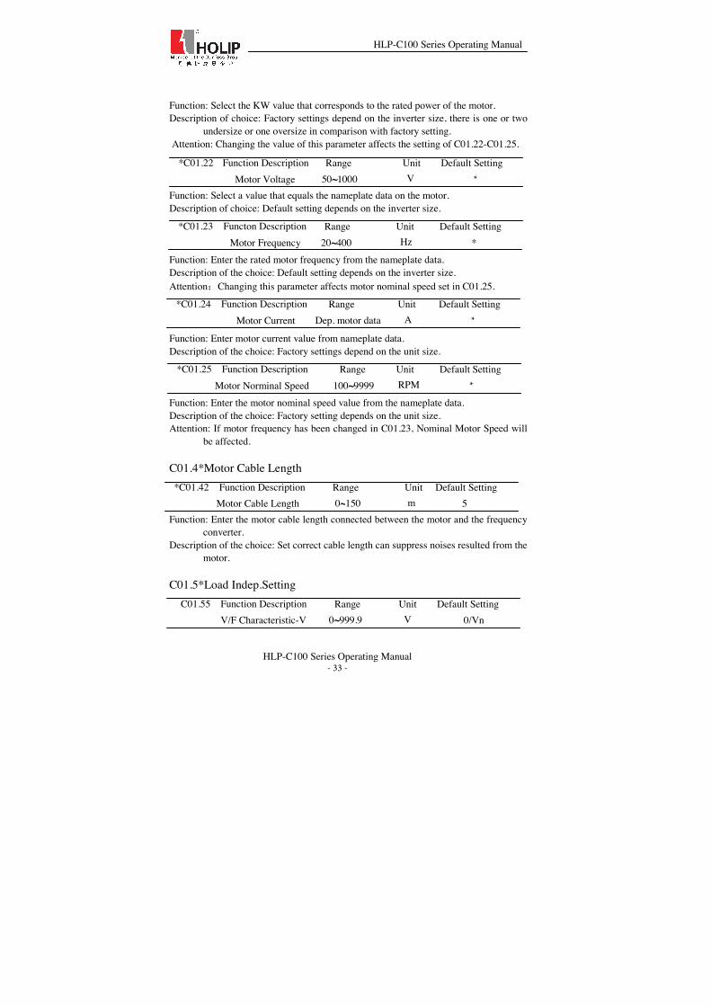
Function: Select the KW value that corresponds to the rated power of the motor. Description of choice: Factory settings depend on the inverter size, there is one or two
undersize or one oversize in comparison with factory setting. Attention: Changing the value of this parameter affects the setting of C01.22-C01.25. Function: Select a value that equals the nameplate data on the motor. Description of choice: Default setting depends on the inverter size.
Function: Enter the rated motor frequency from the nameplate data. Description of the choice: Default setting depends on the inverter size. Attention˖Changing this parameter affects motor nominal speed set in C01.25.
Function: Enter motor current value from nameplate data. Description of the choice: Factory settings depend on the unit size.
Function: Enter the motor nominal speed value from the nameplate data. Description of the choice: Factory setting depends on the unit size. Attention: If motor frequency has been changed in C01.23, Nominal Motor Speed will
be affected.
C01.4*Motor Cable Length
Function: Enter the motor cable length connected between the motor and the frequency converter.
Description of the choice: Set correct cable length can suppress noises resulted from the motor.
C01.5*Load Indep.Setting
*C01.22 Function Description
Range Unit Default Setting Motor Voltage 50~1000 V *
*C01.24 Function Description
Range Unit Default Setting Motor Current Dep. motor data A *
*C01.23 Functon Description
Range Unit Default Setting Motor Frequency 20~400 Hz *
*C01.25 Function Description
Range Unit Default Setting Motor Norminal Speed RPM * 100~9999
*C01.42 Function Description
Range Unit Default Setting Motor Cable Length
0~150
m
5
C01.55 Function Description
Range Unit Default Setting V/F Characteristic-V
0~999.9
V
0/Vn

HLP-C100 Series Operating Manual
HLP-C100 Series Operating Manual - 34 -
Function: This parameter is an array parameter [0-5], used for setting voltage [V0-V5] at each frequency point to manually form a V/F characteristic matching motor. Frequency points are defined in par. C01.56, V/F characteristics - F.
Description of choice: This parameter is only functional when par. C01.01, Motor Control Principle is set to V/F [0].
Attention: V0 factory setting is set to 0V, and U1-U5 factory setting is set to Un˄motor rated voltage˅.
Function: This parameter is an array parameter [0-5], used for setting frequency points [F0-F5] to manually form a V/F characteristic matching motor. Voltage at each point is defined in par. C01.55, V/F Characteristic - V.
Description of choice˖This parameter is only functional when par. C01.01 Motor Control Principle is set to V/F [0].
Attention: F0 factory setting is set to 0Hzˈand F1-F5 factory setting is set to Fn˄Motor rated frequency˅; for par. C01.56 the following applies F0=0 and F1≤F2≤F3≤F4≤F5.
Fig. 6.1 V/F characteristic diagram
Simplify V/F characteristic by merging 2 or more points (voltages and frequencies), which respectively are set equal.
The slope (ratio of V/F) after point (F5ˈV5) must be equal to the slope between point (F5, V5) and the previous point. C01.7*Start Adjustments
Function: This parameter enables a delay of the starting time. The frequency converter begins with the start function selected in par. 1-72. Set the start delay time until acceleration is to begin.
C01.56 Function Description
Range Unit Default Setting V/F Characteristic-F
0~400
Hz
0/Fn
C01.71 Function Description
Range Unit Default Setting Start Delay
0.0~10.0
S
0.0

HLP-C100 Series Operating Manual
HLP-C100 Series Operating Manual - 35 -
Attention: Setting start delay to 0.0 sec. disables Start Function, [C01.72], when start command is given.
Option: [0] DC Hold; [2] Coast;
Function: Select [0], Motor is energized with DC holding current (par. C02.00) during start delay time; Select [2], Motor is coasted during start delay time (inverter off).
Option: [0] Disabled;
[1] Enabled; Description of Choice: This function applies for the inertia load to restart due to mains
drop-out; If Clockwise[0] is selected(C04.10), and no rotating motor is found, It is possible to use DC-brake command to ramp down the motor speed to 0 rpm, and then start the motor in the normal way; If Both directions [2](C04.10) is selected, and no rotating motor is found, the drive will assume the motor is stationary or in low-speed rotation, and then start the motor in the normal way. When Flying start is enabled, C01.71 (Start delay) and C01.72 (Start function) is invalid.
Warning: This function is not suitable for hoisting applications. C01.8*Stop Adjustments
Option: [0] Coast, the inverter is off; [1] DC Hold, the motor is energized with a DC current. See par. C02.00 DC Hold Current for more information.
Function: Here it is possible to select the stop function according to different applications.
C01.72 Function Description
Range Unit Default Setting Start Function
0~2
2
*C01.73 Function Description
Range Unit Default Setting Flying Start
0~1
0
C01.80 Function Description
Range Unit Default Setting Function at Stop
0~1
0

HLP-C100 Series Operating Manual
HLP-C100 Series Operating Manual - 36 -
Start Command ON OFF
C01.82
Output Voltage
Output Frequency
C02.00
Time
Time
Start Command ON OFF
C01.82
Output Voltage
Output Frequency
0V
Time
Time
Coast DC Hold
Description of Choice: This function is active in the following situations: Stop command is given and output speed is ramped down to Min. Speed for activating Functions at Stop; Start command is removed (standby), and output speed is ramped down to Min. Speed for activating Functions at Stop; DC-brake command is given, and lasts out of DC-brake delay time.
Function: Set the output frequency at which to activate par. C01.80 Function at stop.
7.3 Parameter Group 02˖Brakes C02.0*DC -Brake
Function: This parameter either holds the motor (holding torque) or preheats the motor. This parameter is active if DC Hold has been selected in either C01.72 start function or C01.80 Function at Stop.
Description of Choice: Enter a value for holding current as a percentage of the rated motor current set in par. C01.24 Motor Current. 100% DC holding current corresponds to IM,N.
Attention: Avoid 100% current too long as it may overheat the motor.
Function: This parameter is used for setting the DC brake currents that is set as a percentage value of the rated motor current IM, N set in C01.24.
C02.00 Function Description
Range Unit Default Setting DC Hold Current
0~150
%
50
C02.01 Function Description
Range Unit Default Setting DC Brake Current
0~150
%
50
C01.82 Function Description 0.0
Range Unit Default Setting Min Speed for Function at Stop [Hz] Hz
0.0~20.0
C01.82 Function Description 0.0
Range Unit Default Setting Min Speed for Function at Stop [Hz] Hz
0.0~400.0

HLP-C100 Series Operating Manual
HLP-C100 Series Operating Manual - 37 -
Description of Choice: Parameters related to the DC brake current are as follows: DC-brake command, see C05.1* choice˄5˅; DC brake cut in speed, see C02.04;
Function: This parameter defines DC brake current (C02.01) time during which DC-brake current is applied to the motor.
Function: This parameter is for setting the DC brake cut in speed at which the DC braking current (par.02.01) is to be actived, in connection with a stop command. When set to 0 the function is off.
C02.1*Brake Energy Funct.
Option: [0] off; [1] Resistor brake, use the resistor brake to consume surplus energy resulting from motor braking, and prevent the frequency converter to trip due to over-voltage in the intermediate circuit;
Attention: Resistor brake is only functional when the frequency converter build-in braking unit or external braking unit must be installed.
Function: Set brake resistor value.
Option: [0] Disabled, The OVC is not active/required; [2] EnabledˈOVC is running;
Function: OVC is used to consume surplus energy by increasing the output frequency. Select whether to enable OVC, which reduces the risk of drive trip due to over voltage on the DC link caused by generative power from load.
Attention: The OVC is not active/required if resistor brake has been chosen in C02.10 (Brake Function).
7.4 Parameter Group 03: Reference/Ramps C03.0* Reference Limits
C02.02 Function Description
Range Unit Default Setting DC Braking Time
0.0~60.0
S
10.0
C02.04 Function Description
Range Unit Default Setting DC Brake Cut in Speed
0.0~400.0
Hz
0.0
C02.10 Function Description
Range Unit Default Setting Brake Function
0~2
0
C02.11 Function Description
Range Unit Default Setting Brake Resistor (ohm)
5~65535
Ω
*
C02.17 Function Description
Range Unit Default Setting Over-voltage Control
0~2
0

HLP-C100 Series Operating Manual
HLP-C100 Series Operating Manual - 38 -
Function: Enter value for Maximum Reference. Description of Choice: The sum of all internal and external references is clamped
(limited) to the maximum reference value.
C03.1**References
Function: This parameter is an array-8 to be used for presetting different references. Description of Choice: 100%= value set in C03.03; It contains 8 preset references
which are selectable via digital terminals or local bus. See C05.1*. Selection of preset reference indicates with a three-digital binary code. If the frequency converter detects the corresponding terminals connected, then the bit is “1”, otherwise, the bit is “0”. Digital input terminal ǃ binary code and the corresponding relationship between pre-set values as follows:
Binary system bit2 bit1 bit0 Preset Reference
0 0 0 0 0 0 1 1 0 1 0 2 0 1 1 3 1 0 0 4 1 0 1 5 1 1 0 6
Terminals State
1 1 1 7
Function: Jog frequency is a fixed frequency that the drive supplies to the motor after
the jog function is actived. Please refer to C05.1*, select [14]. Description of Choice: The frequency converter with the highest priority will operate at
jog speed when a variety of run command activates. Removing the jog signal makes the frequency converter run according to the selected configuration, this parameter is set limited by C04.14.
Function: This parameter enables the entry of a percentage value (relative) which will to be either added to or deducted from the actual reference.
Description of Choice: The Catch up/Slow down function is activated by a digital input terminal˄See C05.1*ˈchoose [28]/ [29] ˅. If this function is active, the
C03.12 Function Description 0.00
C03.03 Function Description
Range Unit Default Setting Maximum Reference 0.000~4999.000
50.000
C03.10 Function Description
Range Unit Default Setting Preset Reference
-100.00~100.00[8]
%
0.00
C03.11 Function Description
Range Unit Default Setting Jog Speed
0.0~400.0 Hz
5.0
%
Range Unit Default Setting Catch up/Slow down Value
0.00~100.00

HLP-C100 Series Operating Manual
HLP-C100 Series Operating Manual - 39 -
catch up/slow down value will be added to the actual reference constituting new setting at which the frequency converter is going to run, calculated as follows: Total reference= reference freference h (Catch up/Slowdown value) If this function is inactive, the reference returns to its original value (the actual reference). For example: Set C05.12=28ˈC05.13=29ˈC03.12=30ˈassuming the actual reference value is 20 Hz, when only DI1 is on, the output frequency is 26 Hz, when only DI2 is connected, the output frequency is14Hz, when both DI1 and DI2 are on, the output frequency is 20Hz.
Function: Define an adjustable Preset Relative Reference which is to be added to the total reference as a percentage value of the actual reference . Total Reference=Actual Reference+Actual Reference * Preset Relative Reference + Actual reference * Relative Scaling Reference
Example:
Min Reference/C
03.02
Preset Relative
Reference/C03.14
Relative Scaling
Reference
VI/C03.18=1
Preset Reference/C
03.10
Max Reference/C03.
03
Output Frequency(Hz)
0 0% 10V 20% 50 10+0+10=20 0 10% 8V 20% 50 10+1+8=19 0 20% 5V 20% 50 10+2+5=17 0 30% 3V 20% 50 10+3+3=16 0 40% 0V 20% 50 10+4+0=14
Option: [0] No function, no reference resource is defined;
[1] Analog in VIˈuse signals from Analog input VI as reference resource, see C06.1*; [11] Local bus reference, use signals from Local bus reference as reference resource, see C08.9; [21] LCP potentiometer, use signals from LCP potentiometer as reference resource, see C06.8*;
Function: C03.15ǃC03.16 define up to three different reference signals, the sum of which defines is the actual reference.
C03.14 Function Description
Range Unit Default Setting Preset Relative Reference
-100.00~100.00
%
0.00
C03.15 Function Description
Range Unit Default Setting Reference Resource1
0~21
1
C03.16 Function Description
Range Unit Default Setting Reference Resource2
0~21
2
C03.18 Function Description
Range Unit Default Setting Relative Scaling Ref. Resource
0~21
0

HLP-C100 Series Operating Manual
HLP-C100 Series Operating Manual - 40 -
Option: [0] No function: No relative scaling ref. resource is defined; [1] Analog input VI, select analog input VI as relative scaling ref. source, see C06.1*; [11] Local bus reference, select local bus reference as relative scaling ref. source, see par. C08.9*; [21] LCP potentiometer, select LCP potentiometer as relative scaling ref. source, see par. C06.8*; Function: The Relative Scaling Ref. Resource can be set via Analog input terminalsǃLocal bus reference and LCP potentiometer. Total Reference=Actual Reference + Actual reference * Relative Scaling Reference.
Example:
Preset Reference/C03.10
Relative Scaling Reference
VI/C03.18=1
Max Reference/C
03.03 Output Frequency(Hz)
20% 10V 50 10+10=20 20% 8V 50 10+8=18 20% 5V 50 10+5=15 20% 3V 50 10+3=13 20% 0V 50 10+0=10
Option: [0] No Function; [1] Stop Save; [2] Power Down Save;
Function: This parameter is used for setting whether to save the data changed in the Up/Down function if the frequency stops or after it power down.
C03.4*Ramp1
Option: [0] Linear: Motor ramp up to the preset frequency with constant acceleration. [2] S ramp: Motor ramp to the preset frequency with non-linear acceleration.
Description of Choice: If Linear [1] is selected, the frequency may exceed the preset setting during the acceleration; If S ramp [2] is selected, due to smoother S curve, it will automatically adjust acceleration when approaching to the preset frequency to avoid exceeding it.
C03.19 Function Description
Range Unit Default Setting 0~2 Save Speed Up/Down Value
0
C03.40 Function Description
Range Unit Default Setting Ramp 1 Type
0~2
0

HLP-C100 Series Operating Manual
HLP-C100 Series Operating Manual - 41 -
Ramp type and Ramp time
Attention: It is possible to switch acceleration and deceleration via digital input terminals, see parameterC05.1* choice. The state of the digital input terminal is shown in binary code; If the drive detects the corresponding digital input terminals connected, then the bit is”1”, on the contrary is”0”. The corresponding relationship between state of the digital input terminalsǃbinary code and the selected ramp type are as follows:
Binary system bit2 bit1 bit0 Ramp Group 0 0 0 1 0 0 1 2 0 1 0 3 0 1 1 4 1 0 0 5 1 0 1 6 1 1 0 7
Terminal State
1 1 1 8
Function: Enter the ramp-up time from 0 Hz to rated Motor speed in C01.25. Attention: Choose a rame-up time such that the output current does not exceed the
current limit in C04.18.
C03.41 Function Description
Range Unit Default Setting Ramp1Ramp up Time
0.10~300.00
S
*

HLP-C100 Series Operating Manual
HLP-C100 Series Operating Manual - 42 -
Function: Enter the deceleration time from the rated motor speed in C01.25 to 0Hz. Attention: Choose a ramp-down time such that no over-voltage arises in the inverter
due to regenerative operation of motor and such that the generated current does not exceed the current limit set in C04.18.
C03.5*Ramp2
Option: [0] Linear: Motor ramp up to the preset frequency with a constant acceleration;
[2] S-ramp: Motor ramp to the preset frequency with non-linear acceleration..
Function: Enter the ramp-up time from 0Hz to rated Motor speed in C01.25. Attention: Choose a ramp-up time such that the output current does not exceed the
current limit set in C04.18.
Function: Enter the deceleration time from the rated motor speed in C01.25 to 0Hz. Attention: Choose a ramp-down time such that no over-voltage arises in the inverter
due to regenerative operation of motor and such that the generated current does not exceed the current limit set in C04.18.
C03.6*Ramp3
Option: [0] Linear˖Motor ramp up to the preset frequency with a constant acceleration;
[2] S-ramp: Motor ramp to the preset frequency with non-linear acceleration..
Function: Enter the acceleration time from 0Hz to rated Motor speed in C01.25. Attention: Choose a ramp-up time such that the output current does not exceed the
current limit set in C04.18.
Function: Enter the deceleration time from the rated motor speed in C01.25 to 0Hz.
C03.60 Function Description
Range Unit Default Setting Ramp3 Type
0~2
0
C03.42 Function Description
Range Unit Default Setting Ramp1 Ramp Down Time
0.10~300.00
S
*
C03.50 Function Description
Range Unit Default Setting Ramp2 Type
0~2
0
C03.51 Function Description
Range Unit Default Setting Ramp2 Ramp up Time
0.10~300.00
s
*
C03.52 Function Description
Range Unit Default Setting Ramp2 Ramp down Time
0.10~300.00
S
*
C03.61 Function Description
Range Unit Default Setting Ramp3 Ramp up Time
0.10~300.00
S
*
C03.62 Function Description
Range Unit Default Setting Ramp3 Ramp Down Time
0.10~300.00
S
*

HLP-C100 Series Operating Manual
HLP-C100 Series Operating Manual - 43 -
Attention: Choose a ramp-down time such that no over-voltage arises in the inverter due to regenerative operation of motor and such that the generated current does not exceed the current limit set in C04.18.
C03.7*Ramp4
Option: [0] Linear: Motor ramp up to the preset frequency with a constant acceleration; [2] S-ramp: Motor ramp to the preset frequency with non-linear acceleration.
Function: Enter acceleration time from 0Hz to rated Motor speed in C01.25. Attention: Choose a ramp-up time such that the output current does not exceed the
current limit set in C04.18.
Function: Enter the deceleration time from the rated motor speed in C01.25 to 0Hz. Attention: Choose a ramp-down time such that no over-voltage arises in the inverter
due to regenerative operation of motor and such that the generated current does not exceed the current limit set in C04.18.
C03.8*Other Ramps
Function: Enter the time required motor speed from 0Hz up to rated motor speed (C01.25) or from the rated motor speed (C01.25) down to 0Hz.
Description of Choice: Jog ramp time starts upon activation of a jog signal via a selected digital input or serial communication port. See C05.1, choose [14].
Option: [0] Linear: Motor ramp up to the preset frequency with a constant acceleration;
[2] S-ramp: Motor ramp to the preset frequency with non-linear acceleration.
Function: Enter acceleration time from 0Hz to rated Motor speed in C01.25. Attention: Choose a ramp-up time such that the output current does not exceed the
current limit set in C04.18.
C03.70 Function Description
Range Unit Default Setting Ramp4 Type
0~2
0
C03.71 Function Description
Range Unit Default Setting Ramp4 Ramp up Time
0.10~300.00
S
*
C03.72 Function Description
Range Unit Default Setting Ramp4 Ramp Down Time
0.10~300.00
S
*
C03.80 Function Description
Range Unit Default Setting Jog Ramp Time
0.10~300.00 S
*
C03.85 Function Description
Range Unit Default Setting Ramp5 Ramp up Time 0.10~300.00 S
*
C03.84 Function Description
Range Unit Default Setting Ramp5 Type
0~2
0

HLP-C100 Series Operating Manual
HLP-C100 Series Operating Manual - 44 -
Function: Enter the deceleration time from the rated motor speed in C01.25 to 0Hz. Attention: Choose a ramp-down time such that no over-voltage arises in the inverter
due to regenerative operation of motor and such that the generated current does not exceed the current limit set in C04.18.
selected digital input or serial communication port. See C05.1, choose [14].
Option: [0] Linear: Motor ramp up to the preset frequency with a constant acceleration;
[2] S-ramp: Motor ramp to the preset frequency with non-linear acceleration.
Function: Enter acceleration time from 0Hz to rated Motor speed in C01.25. Attention: Choose a ramp-up time such that the output current does not exceed the
current limit set in C04.18.
Function: Enter the deceleration time from the rated motor speed in C01.25 to 0Hz.
C03.86 Function Description
Range Unit Default Setting Ramp5 Ramp Down Time
0.10~300.00
S
*
C03.88 Function Description
Range Unit Default Setting Ramp6 Ramp up Time 0.10~300.00 S
*
C03.87 Function Description
Range Unit Default Setting Ramp6 Type
0~2
0
C03.89 Function Description
Range Unit Default Setting Ramp6 Ramp Down Time
0.10~300.00
S
*
C03.91 Function Description
Range Unit Default Setting Ramp7 Ramp up Time 0.10~300.00 S
*
C03.90 Function Description
Range Unit Default Setting Ramp7 Type
0~2
0
C03.92 Function Description
Range Unit Default Setting Ramp7 Ramp Down Time
0.10~300.00
S
*

HLP-C100 Series Operating Manual
HLP-C100 Series Operating Manual - 45 -
Attention: Choose a ramp-down time such that no over-voltage arises in the inverter due to regenerative operation of motor and such that the generated current does not exceed the current limit set in C04.18.
selected digital input or serial communication port. See C05.1, choose [14].
Option: [0] Linear: Motor ramp up to the preset frequency with a constant acceleration;
[2] S-ramp: Motor ramp to the preset frequency with non-linear acceleration.
Function: Enter acceleration time from 0Hz to rated Motor speed in C01.25. Attention: Choose a ramp-up time such that the output current does not exceed the
current limit set in C04.18.
Function: Enter the deceleration time from the rated motor speed in C01.25 to 0Hz. Attention: Choose a ramp-down time such that no over-voltage arises in the inverter
due to regenerative operation of motor and such that the generated current does not exceed the current limit set in C04.18.
Option: [0] No link; [1] Link.
Function: If choose [1] link preset reference and ramp time, preset reference 0-7 are corresponding to ramp time 1-8. For example, choose preset reference 2 by using terminals control, the ramp time is 3.
7.5 Parameter Group 04: Limits/warnings C04.1*Motor Limits
Option: [0] Clockwise, the motor shaft rotates in clockwise direction; this setting prevents the motor from running in counter clockwise direction. [1] Counter clockwise, motor shaft rotates in counter clockwise direction, this setting prevents the motor from running in clockwise direction. [2] Both Directionsˈwith this setting, the motor can run in both directions.
*C04.10 Function Description
Range Unit Default Setting Motor Speed Direction
0~2
2
*C04.12 Function Description
Range Unit Default Setting Motor Speed Low Limit
0.0~400.0
Hz
0.0
C03.94 Function Description
Range Unit Default Setting Ramp8 Ramp up Time 0.10~300.00 S
*
C03.93 Function Description
Range Unit Default Setting Ramp8 Type
0~2
0
C03.95 Function Description
Range Unit Default Setting Ramp8 Ramp Down Time
0.10~300.00
S
*
C03.96 Function Description
Range Unit Default Setting Link preset reference and ramp time
0.10~300.00
S
*

HLP-C100 Series Operating Manual
HLP-C100 Series Operating Manual - 46 -
Function: Set the minimum limit for Motor Speed, the motor speed low limit can be set to correspond to the minimum output frequency of the motor shaft . The motor speed low limit must not exceed the Motor Speed High Limit in C04.14.
Function: Enter the maximum limit for Motor Speed , the motor speed high limit can be set to correspond to the maximum manufacture’s rated motor speed. The motor speed high limit must exceed the Motor Speed Low Limit in C04.19.
Function: Set the output current high limit. Attention: If a setting in C01.20 to C01.25 is changed, this parameter is not
automatically reset to default setting.
Function: Enter value of the maximum output frequency.
C04.5*Adj. Warnings
Function: Enter the nlow value, when the motor speed falls below this limit, the display reads Speed Low.
Attention: This setting must be within normal motor frequency range, otherwise, it may trigger an error warning.
Function: Enter the nhigh value, when the motor speed exceeds this limit, the display reads Speed High.
Attention: This setting must be within normal motor frequency range, otherwise, it may trigger an error warning.
Option: [0] Off, functoin is disabled; [1] On, function is enabled;
Attention: Missing motor phase causes motor torque to decrease. This function may be disabled for special purpose (e.g. small motor running pure U/f mode). However, choosing [0] Off, function disabled, may lead to overheating, Holip strongly recommends to make an active setting to avoid motor damage.
*C04.14 Function Description
Range Unit Default Setting Motor Speed High Limit
0.0~400.0
Hz
65.0
C04.18 Function Description
Range Unit Default Setting Current Limit
0~300
%
150
*C04.19 Function Description
Range Unit Default Setting Max Output Frequency
0.0~400.0
Hz
65
C04.52 Function Description
Range Unit Default Setting Warning Speed Low
0.0~400.0
Hz
0.0
C04.53 Function Description
Range Unit Default Setting Warning Speed High
0.1~400.0
Hz
65.0
*C04.58 Function Description Missing Motor Phase Function
0~1
1
Range Unit Default Setting

HLP-C100 Series Operating Manual
HLP-C100 Series Operating Manual - 47 -
C04.6*Speed Bypass
Array: [3] Function: This parameter is a dyadic Array, [0] is used to set the bypass speed from of
bypass speed range 1, [1] is used to set the bypass speed from of bypass speed range 2,and [2] is used to set that of bypass speed range3.
Description of Choice: Some systems call for avoiding some certain output speed due to resonance problems in system. The drive will pass quickly when it approaching to the Bypass Speed area.
Array: [3]; Function: This parameter is a dyadic array, [0] is used to set the bypass speed to of
bypass speed range 1, [1] is used to set the bypass speed to of bypass speed range 2,and [2] is set as that of bypass speed range3.
7.6 Parameter Group 05: Digital Input/Output C05.1*Digital Input
C04.61 Function Description
Range Unit Default Setting Bypass Speed From
0.0~400.0
Hz
0.0
C04.63 Function Description
Range Unit Default Setting Bypass Speed to
0.0~400.0
Hz
0.0
C05.10 Function Description
Range Unit Default Setting Terminal FOR Digital Input
0~36
8
C05.12 Function Description
Range Unit Default Setting Terminal DI1Digital Input Input
0~36
15 C05.13 Function Description
Range Unit Default Setting
Terminal DI2Digital Input DI2
0~36
16
C05.11 Function Description
Range Unit Default Setting Terminal REV Digital Input
0~36
10
C04.63[1]C04.61[1]
C04.63[0]C04.61[0] Bypass Speed
Range 1
Bypass Speed Range 2
time
Output frequency
Bypass Speed Range 3
C04.63[2]C04.61[2]

HLP-C100 Series Operating Manual
HLP-C100 Series Operating Manual - 48 -
Option: [0] No operation, the frequency converter will not to react to signals transmitted to the terminal; [1] Reset, reset the frequency converter after a Trip/Alarm; [2] Coast Inverse, no output, leaving the motor coasting to stop; [5] DC-brake Inverse, see C02.01ˈthis function is only active when value in C02.02 and C02.04 are different from 0. [6] Stop Inverseˈthe drive is stopped according to selected ramp time; [8] Start, 1=start, 0=stop; [10] Reversingˈchange direction of motor shaft rotation, reversing signal only changes direction of rotation, it does not activate start function, C04.10 must choose [2] Both directions; [11] Start reversing, used for start/stop and for reversing at the same time; [14] Jog, used for activating jog speed, see C03.11; [15] Preset ref. bit0ˈPreset ref.bit0ǃbit1ǃbit2ǃbit3 is used for the choice of the preset reference, see parC03.10; [16] Preset ref. bit1ˈsame as[15]; [17] Preset ref. bit2ˈsame as [15]; [28] Catch upˈselect catch up to increase the resulting reference value by the percentage set in par. C03.12; [29] Slow down, select slow down to reduce the resulting reference value by the percentage set in par. C03.12; [34] Ramp bit0ǃ bit0ǃbit1ǃbit2 used for select acceleration or deceleration; [35] Ramp bit1ˈsame as [34]˗ [36] Ramp bit2ˈsame as [34]˗
C05.4*Relay Option: [0]No operation;
[5]Drive running, Motor is running; [9]Alarm. Frequency converter alarms; [10]Alarm or warning. An alarm or warning occurs; [15]Beyond frequency range. Output frequency beyond range set in C04.52 and C04.53; [16]Below frequency, low. Output frequency is lower than value set in C04.52; [17]Above frequency,high. Output frequency is higher than value set in C04.53; [21] Thermal warning. A thermal warning occurs; [24]Ready-Voltage OK. Frequency converter is ready for operation, main voltage is within specified voltage range;
C05.14 Function Description
Range Unit Default Setting Terminal DI3Digital Input
0~36
17
C05.40 Function Description
Range Unit Default Setting Relay Function
0~55
5

HLP-C100 Series Operating Manual
HLP-C100 Series Operating Manual - 49 -
[25] Reverse. Motor runs in counter clockwise; [26] Bus OK. Local bus communication is normal; [28] Brake-No warning. Brake is active, and no warnings are present; [53]No alarm. Frequency converter is running normally, no alarm; [55]Running reverse. Drive runs in counter clockwise;
7.7 Parameter Group 06: Analog In/Out C06.1*Analoge Input 1
Function: Enter VI Low Voltage corresponding to Min. reference/feedback set in
C06.14.
Function: Enter VI High Voltage corresponding to Max. reference/feedback set in
C06.15.
Function: Enter VI Low Current corresponding to Min. reference/feedback set in C06.14.
Function: Enter VI High Current corresponding to Max. reference/feedback set in C06.15.
Function: Enter VI Low Ref./Feedb. Corresponding to Min. voltage or min. current set
in C06.10 or C06.12.
Function: Enter VI High Ref./Feedb. Corresponding to max voltage or max current set in C06.11 or C06.13.
C06.15 Function Description
Range Unit Default Setting Terminal VI High Ref. /Feedb.
-4999.000~4999.000
50.000
C06.10 Function Description
Range Unit Default Setting Terminal VI Low Voltage
0.00~9.99
V
0.07
C06.11 Function Description
Range Unit Default Setting Terminal VI High voltage
0.10~10.00
V
10.00
C06.12 Function Description
Range Unit Default Setting Terminal VI Low Current
0.00~19.99
mA
0.14
C06.13 Function Description
Range Unit Default Setting Terminal VI High Current
0.01~20.00
mA
20.00
C06.14 Function Description
Range Unit Default Setting Terminal VI Low Ref. /Feedb.
-4999.000~4999.000
0.000

HLP-C100 Series Operating Manual
HLP-C100 Series Operating Manual - 50 -
Function: Enter the time constant, this is a first-order digital low pass filter time constant for suppressing electrical noise in analog input VI. A high time constant value improves dampening but also increases the time delay through the filter. This parameter can’t be adjusted while the motor is running.
Function: Set the dead-band of VI at 0 speed. When analog input VI ref. low and ref. high have opposite signs, there must be a set point that corresponding to an analogue value equals 0. In order to prevent the set point jitter at zero point due to analog interference, this parameter should be set properly.
Description of Choice: Point A as shown in the figure is the analog value that
corresponds to a setpoint that equals 0. It is calculated via analog lowǃhigh values and lowǃhigh references. UAB=UAC=C06.18/2
Option: [0] Voltage mode; [1] Current mode;
Function: Select the input to be present on analog input VI.
C06.16 Function Description
Range Unit Default Setting Terminal Filter Time Constant
0.01~10.00
s
0.01
C06.18 Function Description
Range Unit Default Setting Terminal VI Zero Dead Band 0.00~20.00
V/mA
0.00
C06.19 Function Description
Range Unit Default Setting Terminal VI Mode 0~1
0

HLP-C100 Series Operating Manual
HLP-C100 Series Operating Manual - 51 -
C06.8*LCP Potmeter
The LCP potmeter can be select either as reference resource or relative reference resource.
Function: This reference value corresponding to potentiometer turned fully
counterwise .
Function: This reference value corresponding to potentiometer turned fully clockwise.
7.8 Parameter Group 07: Controller C07.2*Process Ctrl. Feedb
Option: [0] No Function; [1] Analog in VI(0-10 Vǃ0-20 mA ǃ 4-20 mA); [11] Local Bus˄0 ~ ± 200%˅;
Function: Select resource of feedback signal. C07.3*Process PI Ctrl.
This parameter is active in closed loop process control mode.
Option: [0] Disable, continue regulation of a given error even when the output frequency can’t be increased/decreased.
[1] Enable, ceases regulation of a given error when the output frequency can’t be increased/decreased.
Function: This function ensures the output frequency reaches to frequency limit. PI-controller will be initialized to the current frequency when the output frequency can not be changed. This can prevent the integrator continue to integrate on an error when the PI-controller can’t adjust output frequency.
Function: The proportional Gain indicates the number of times the error between the set point and the feedback signal is to be applied. Quick control is obtained by a high gain, but if the gain is too high, the process may become unstable.
C06.81 Function Description
Range Unit Default Setting LCP Potmeter Low Ref.
-4999.000~4999.000
0.000
C06.82 Function Description
Range Unit Default Setting LCP Potmeter High Ref.
-4999.000~4999.000
50.000
C07.20 Function Description
Range Unit Default Setting Process CL Feedback 1
Resource 0~11
0
C07.31 Function Description
Range Unit Default Setting Process PI Anti Windup
0~1
1
C07.33 Function Description
Range Unit Default Setting Process PI Proportional Gain
0.0~10.00
0.01

HLP-C100 Series Operating Manual
HLP-C100 Series Operating Manual - 52 -
Attention: This function is disabled when it is set to “0”.
Function: The integral time is the time needed by the integrator to reach the same gain
as the porortional gain. Quick control is obtained at a short integral time, however, this time may become too short, which can make the process unstable.
Function: Feed Forward Factor acts an antidampening role to the PI action, setting this parameter to optimize the PI controller.
Description of Choice: The PI control error occurs according to the deviation between the setpoint and the feedback , when the deviation is less than set value in this parameter, On reference Band Width function is active.
Function: Process PI controller output low limit, 100% corresponds to C04.19. Function: Process PI controller output High limit, 100% corresponds to C04.19.
7.9 Parameter Group 08: Comm. and Options C08.0*Comm. General Settings
Option: [0] Digital and control word , use both digital input and control word as control; [1] Digital only, use digital input as control; [2] Control word only, use control word only as control;
Option: [0] None, control word is inactive; [1] FC RS485 , select local bus as control word source.
C07.34 Function Description
Range Unit Default Setting Process PI Integral Time 0.10~9999.00
s
9999.00
C07.38 Function Description
Range Unit Default Setting Process PI Feed Forward Factor
0~400 %
0
C07.39 Function Description
Range Unit Default Setting On reference Band Width
0~200 %
5
C08.01 Function Description
Range Unit Default Setting Control mode
0~2
0
C08.02 Function Description
Range Unit Default Setting Control Word Source
0~1
1
C08.03 Function Description
Range Unit Default Setting Control Word Time Out Time
0.1~6500.0 s
1.0
C07.41 Function Description
Range Unit Default Setting Process PI Output Low
-100-100 %
0
C07.42 Function Description
Range Unit Default Setting Process PI Output High
-100-100 %
100

HLP-C100 Series Operating Manual
HLP-C100 Series Operating Manual - 53 -
Function: This function is disabled, when the reference is set to 0. If the reference is not set to 0, the control word timeout time is not exceeded, and the serial communication is still innormal, action set in C08.04 will be carried out.
Option: [0] Off, No function; [1] Freeze output, Freeze output until communication resumes. [2] Stop, Stop with auto restart when communication resumes; [3] Jogging, Run motor at jog frequency until communication resumes; [4] Max. speed, Run motor at max.frequency until communication resumes; [5] Stop and trip, Stop motor and restart frequency in order to restart via either LCP or Digital input .
Function: Select action to be taken in case of timeout.
Option: [0] No function Control word timeout is not reset; [1] Do reset Control word timeout is reset;
Function: Resetting control word timeout will remove any timeout function;
C08.3*FC Port Setting
Function: Select the address for the bus.
Option: [0] 2400; [1] 4800; [2] 9600; [3] 19200; [4] 38400;
Function: Select baud rate for Port. Attention˖Changing baud rate is effective after responding to any ongoing bus-
requests.
Option: [0] Even parity (1 stop bit); [1] Odd parity˄1 stop bit˅; [2] No parity˄1 stop bit˅; [3] No parity˄2 stop bit˅;
C08.04 Function Description
Range Unit Default Setting Contol Word Time Out Time
0~5
0
C08.06 Function Description
Range Unit Default Setting Reset Control Word Time Out
0~1
0
C08.31 Function Description
Range Unit Default Setting Address
0~247
1
C08.32 Function Description
Range Unit Default Setting Port Baud Rate
0~9
bit/s
2
C08.33 Function Description
Range Unit Default Setting Port Parity
0~3
2
C08.35 Function Description
Range Unit Default Setting Min. Response Delay
0.001~0.500
s
0.010

HLP-C100 Series Operating Manual
HLP-C100 Series Operating Manual - 54 -
Function: Define the minmum delay time from receiving a request to transmitting the
respond out.
Function: Specify maximum permissible delay time between transmitting a request and
receiving a respond. Exceeding this time delay will cause word timeout. C08.9*Bus Jog/Feedback
Function: Enter the value to be used as bus-feedback. Hex-value 4000H corresponds to 100% feedback/range is +/-200%.
7.10 Parameter Group 14: Special Functions
Option: [2] - [6] 2-6kHz; [7] 8kHz; [8] 10kHz; [9] 12kHz; [10] 16kHz;
Description of choice: Switching frequency of the frequency converter has a significant influence to the inverter and the motor. Select appropriate switch frequency can help to adjust acoustic noise from the motorǃpower consumption and the inverter efficiency. When switching frequency increases, the consumption and the noise of the motor are reduced, but the drive’s temperature will increase, and motor leakage and the interference to the external device will increase; the contrary the opposite.
Option: [0] Off, Disable the overmodulation function to avoid torque ripple on the motor shaft; [1] On, Connects the overmodulation function to obtain an output voltage up to 15% greater than mains voltage;
Function: This feature allows more accurate speed control near and over normal speed (50/60HZ). Another advantage with overmodulation is the ability of staying at a constant speed even though mains fault occurs.
C08.36 Function Description
Range Unit Default Setting Max. Response Delay
0.010~10.000 s
5.000
C08.94 Function Description
Range Unit Default Setting Bus Feedback 1
-32768~32767
0
C14.01 Function Description
Range Unit Default Setting Switching Frequency
0~10
5
*C14.03 Function Description
Range Unit Default Setting Over modulation
0~1
1
C14.08 Function Description
Range Unit Default Setting Damping Gain Factor
0~200 %
96

HLP-C100 Series Operating Manual
HLP-C100 Series Operating Manual - 55 -
Function: Damping gain factor can help to improve the response speed of the DC link
of the frequency converter making the DC loop signal more smooth. C14.1*Mains On/Off
Option: [0] Trip, frequency converter trips; [1] Warning, frequency converter issues a warning (but continues to run); [2] Disabled, no action is taken;
Function: Select actions when a severe mains imbalance is detected. C14.2*Trip Reset
Option: [0] Manual reset, perform reset via [reset]-button or digital inputs; [1] - [10] Auto reset 1-10, can perform 1-10 automatic resets after trips; [11] Auto reset11, can perform 15 automatic resets after trips; [12] Auto reset12, can perform 20 automatic resets after trips; [13] Infinite auto reset, can perform an infinite number of automatic resets after tripping;
Function: Select reset function after tripping. Once auto reset is selected, the frequency converter will be restarted after an alarm. If reset have been done and the running signal is active, frequency converter will restart automatically.
Attention: If the auto reset mode is selected, the frequency converter may possibly restart automatically after the alarm disappear.
Function: Enter time interval from trip to start of automatic reset function after a warning/alarm.
Description of Choice: This parameter is active when C14.20, Auto Reset, is set to Automatic reset [1]-[13].
Option: [0] Normal operation; [2] Initialization, initialise all the parameters except information about the inverter itself and the recorded parameters. [3] Backup user settings; [4] Recover user settings;
C14.12 Function Description
Range Unit Default Setting Function at Mains Imbanlance
0~2 0
C14.20 Function Description
Range Unit Default Setting Reset Mode
0~13 0
C14.21 Function Description
Range Unit Default Setting Automatic Restart Time
0~600
s
10
C14.22 Function Description
Range Unit Default Setting Operation Mode
0~4
0

HLP-C100 Series Operating Manual
HLP-C100 Series Operating Manual - 56 -
Function: After modifying the inverter parameters based on the functional requirements, OEM manufacturers can set C14.22 = 3 to backup settings. If the end user modify parameters and can not be self-recovery, it can be recovered by setting C14.22 = 4 or pressing "OFF" key on LCP 5 seconds. C14.5*DC Voltage Compensation
Option: [0] Disable; [1] Enable;
Function: This function ensures the output voltage is independent of any voltage fluctuations in the DC link . Low torque ripple. In some cases, this dynamic compensation may cause resonance problems in DC link circuit and then this function should be disabled.
7.11 Parameter Group 15: Drive Information C15.0*Operating Data
Function: View how many days the drive has run. The value is saved automatically at power off and can’t be reset.
Function: View the power consumption from mains in Kwh as a mean value over one hour. Reset the counter in C15.06.
Function: View the number of times the drive has been powered up. This parameter
can’t be reset. Option: [0] Do not reset;
[1] Reset counter, Counter is reset; Attention: This parameter can’t be set via local bus. C15.3*Fault Log
*C14.51 Function Description
Range Unit Default Setting DC-LinkVoltage Compensation
0~1
0
C15.00 Function Description
Range Unit Default Setting Operating Days
0~9999
d
C15.02 Function Description
Range Unit Default Setting KWh Counter˄kW˅ 0~65535
KW
C15.03 Function Description
Range Unit Default Setting Power Up’s
0~2147483647
C15.06 Function Description
Range Unit Default Setting Reset Kwh Counter
0~1
C15.30 Function Description
Range Unit Default Setting Fault Log:Error Code
0~255

HLP-C100 Series Operating Manual
HLP-C100 Series Operating Manual - 57 -
Function: View the error code, and look up its meaning in chapter 10. This parameter
group contains a fault log showing reasons for the ten latest trips. Function: This parameter contains internal fault reasons, mostly used in combination
with alarm 38. C15.4*ǃC15.5*Drive Identification
This parameter contains read only information about the hardware and software configuration of the frequency converter. Description of Choice: View FC Type. Description of Choice: View the power size of the frequency converter. Description of Choice: View the voltage level corresponding to different type of
drives. Description of Choice: View the software version of the drive. Description of Choice: View the ordered type code of the drive. Function: View the ordering number of the drive. Description of Choice: View ordering number of the FC. Description of Choice: View ordering number of the power card.
C15.31 Function Description
Range Unit Default Setting Internal Fault Reason
-32767~32767
C15.40 Function Description
Range Unit Default Setting FC Type
C15.41 Function Description
Range Unit Default Setting Power Section
C15.42 Function Description
Range Unit Default Setting Voltage
C15.43 Function Description
Range Unit Default Setting Software version
C15.44 Function Description
Range Unit Default Setting Ordered Type Code
C15.46 Function Description
Range Unit Default Setting FC ordering No.
C15.47 Function Description
Range Unit Default Setting Power Card Ordering No.
C15.49 Function Description
Range Unit Default Setting Software ID Control Card

HLP-C100 Series Operating Manual
HLP-C100 Series Operating Manual - 58 -
Description of Choice: View the control card ID number. Description of Choice: View the power card ID number. Description of Choice: View the drives serial number. Description of Choice: View power card serial number. C15.5*Defined parameters Function: View drive parameters that has been defined.
7.12 Parameter Group 16: Data Readouts This parameter group is read-only.
C16.0*General Status
Function: View the total remote reference, the total reference is sum of pulse, analog, preset, LCP Potmeter, local bus and freeze reference.
Function: View motor speed. C16.1*Motor Status
Function: View output power in KW.
Function: View motor phase voltage.
C15.50 Function Description
Range Unit Default Setting Software ID Power Card
C15.51 Function Description
Range Unit Default Setting FC Serial Number
C15.53 Function Description
Range Unit Default Setting Power Card Serial Number
C15.92 Function Description
Range Unit Default Setting Parameter List
C16.01 Function Description
Range Unit Default Setting Reference
-4999.000~4999.000
C16.05 Function Description
Range Unit Default Setting Motor Speed [RPM]
0~9999 200.0
Hz
C16.10 Function Description
Range Unit Default Setting Power˄kW˅ 0.000~1000.000
kW
C16.12 Function Description
Range Unit Default Setting Motor Voltage
0~65535
V

HLP-C100 Series Operating Manual
HLP-C100 Series Operating Manual - 59 -
Function: View output frequency.
Function: View motor phase current. C16.3*Drive Status
Function: View DC-link voltage.
Function: View the temperature of drive’s heatsink.
C16.5*Ref./Feedb.
Function: View analog or pulse feedback in HZ. C16.6*ǃC16.7*Inputs and Outputs
Function: View signal states from active digital inputs, which indicates in a 16-bit binary code. If the drive detects digital input terminals connected, the corresponding position is set to “1”, otherwise “0”. Digital input terminal and the corresponding relationship between the binary code are as below:
Binary Term. No. Binary Term. No. Binary Term. No. Binary Term. No.
bit0 FOR bit4 DI3 bit8 Reserved bit12 Reserved bit1 REV bit5 Reserved bit9 Reserved bit13 Reserved bit2 DI1 bit6 Reserved bit10 Reserved bit14 Reserved bit3 DI2 bit7 Reserved bit11 Reserved bit15 Reserved
Function: View actual input voltage or current value on analog input VI.
C16.13 Function Description
Range Unit Default Setting Frequency
0.0~400.0
Hz
C16.14 Function Description
Range Unit Default Setting Motor Current
0.00~655.35
A
C16.30 Function Description
Range Unit Default Setting DC Link Voltage
0~65535 V
C16.34 Function Description
Range Unit Default Setting Inverter Temp.
0~255 ć
C16.52 Function Description
Range Unit Default Setting Feedback
-4999.000~4999.000
C16.60 Function Description
Range Unit Default Setting Digital Input
0~65535
C16.62 Function Description
Range Unit Default Setting Analog Input VI
0.00~20.00 V/mA

HLP-C100 Series Operating Manual
HLP-C100 Series Operating Manual - 60 -
Function: View the output status of the relay, the corresponding bit is set to “1”when the relay output is active, otherwise it will be set to “0”.
Binary bit0 Item. No. Relay 1
C16.8*Field bus/FC Port
Function: View the last received reference from the FC port.
C16.9*Diagnosis Readouts
Function: View the alarm word sent via the serial communication port in hex code. Convert this parameter to a 32-bit binary code, definition of the bits in alarm word showed in the table below, among which that reserved by manufacturers are undefined bits:
Binary Alarm Word /C16.90
Alarm Word 2 /C16.91
Warning Word /C16.92
Warning Word 2 /C16.93
0 Brake detect Undefined Undefined Undefined
1 Power Card over Temp. Undefined Power Card over
Temp. Undefined
2 Earth Fault Trip Earth Fault Undefined 3 Undefined Option part Undefined Undefined
4 Control Card Temp Undefined Control Card Temp Undefined
5 Over Current Undefined Over Current Undefined 6 Torque Limit Undefined Undefined Undefined 7 Undefined Undefined Undefined Undefined 8 Undefined Damaged part Undefined Damaged part 9 Inverter Overload Undefined Inverter Overload Undefined
10 DC Under Volt Undefined DC Under Volt Undefined 11 DC Over Volt Undefined DC Over Volt Undefined 12 Short Circuit External Interlock Undefined Undefined 13 Undefined Undefined Undefined Undefined 14 Mains ph. loss Undefined Mains ph. loss Undefined 15 Undefined Undefined No motor Undefined
C16.71 Function Description
Range Unit Default Setting Relay Output
0~65535
C16.86 Function Description
Range Unit Default Setting FC Port Reference
-32768~32767
C16.90 Function Description
Range Unit Default Setting Alarm Word
0~0xFFFFFFFFUL

HLP-C100 Series Operating Manual
HLP-C100 Series Operating Manual - 61 -
16 Live zero error Undefined Live zero error Undefined 17 Internal Fault Undefined Undefined Undefined 18 Brake overload Fan Fault Brake overload Fan Fault 19 U phase loss Undefined Undefined Undefined 20 V phase loss Undefined Undefined Undefined 21 W phase loss Undefined Undefined Undefined 22 Undefined Undefined Undefined Undefined
23 Control Voltage Fault Undefined Undefined Undefined
24 Undefined Undefined Undefined Undefined 25 Undefined Undefined Current Limit Undefined
26 Brake resistor error Undefined Undefined Undefined
27 Brake transistor fault Undefined Undefined Undefined
28 Bake transistor open circuit Undefined Undefined Undefined
29 Drive initialize Feedback error Undefined Feedback error 30 Undefined Undefined Undefined Undefined 31 Mech. Brake low Undefined Undefined Undefined
Function: View the Alarm Word sent via serial communication port in hex code.
Function: View the Warning Word 1 sent via serial communication port in hex code.
Function: View Warning Word 2 sent via serial communication port in hex code.
Chapter 8 Accessory Specification 8.1 Braking Resistor
When the motor acts as a generator, the braking resistor consumes surplus energy resulting from motor braking to achieve fast stop. And to prevent the intermediate circuit voltage is too high to trip eventually.
C16.91 Function Description Range Unit Default Setting Alarm Word 2
0~0xFFFFFFFFUF
C16.92 Function Description Range Unit Default Setting Warning Word 1
0~0x7FFFFFFFUF
C16.93 Function Description Range Unit Default Setting Warning Word 2
0~0x7FFFFFFFUF

HLP-C100 Series Operating Manual
HLP-C100 Series Operating Manual - 62 -
Note: The braking resistor will be very hot, and will have a risk of fire, if the transistor in the braking unit is damaged and shorted. The installation length of the braking resistor should be not less than 5 meters.
Brake resistor (option): Braking Resistor Specification Model
Ω KW Suitable Motor(KW)
HLP-C1000D3721 310 0.25 0.37 HLP- C1000D7521 145 0.065 0.75 HLP- C10001D521 65 0.25 1.5 HLP- C1000D3723 310 0.25 0.37 HLP- C1000D7523 145 0.065 0.75 HLP- C10001D523 65 0.25 1.5 HLP- C1000D7543 620 0.065 0.75 HLP- C10001D543 310 0.25 1.5 HLP- C10002D243 210 0.285 2.2
Note: An external braking unit is needed when connecting braking resistor for the FC which power is less than 220V/380V 0.75kW(included) .
Chapter 9 EMC 9.1 EMC–Correct Installation
HLP-B serials drive implement the latest international standards, following these guidelines is advised, IEC/EN61800-3˖2004 (Adjustable speed electrical power drive systems part 3: EMC requirements and specific test methods). In order to achieve the using requirements of the EMC, must meet the following specifications:
• Using shield motor cables, and connect it to the decoupling device (optional) and the metal motor cabinet;
• To reduce the noise and the leakage current, use the motor cable as short as possible;
• The entire system need to have a good earthling; • RFI Switch screw must be tightened up.
9.2 RFI Switch Use the RFI switch screw to remove the internal EMC filter, if the frequency
converter is supplied from IT or TN Grid . If a drive with EMC filter is connected to the IT grid, then the system may be grounded through the EMC filter capacitors, this may cause damage to the inverter. If a drive with EMC filter is connected to the TN grid, the drive may be burned. Remove the RFI switch can help to reduce the leakage currents.
Chapter 10 Warnings/Alarms and Fault Handling

HLP-C100 Series Operating Manual
HLP-C100 Series Operating Manual - 63 -
10.1 Fault List No.
Code Fault
Description Warning Alarm/Trip Trip/Lock Error Reason analysis
2 Live zero
error
X X
Signal on analog input terminal VI is lower
than 50% of value set in C06.10ǃC06.12
and C06.22
3 Motor Loss X Motor cable connection problems
4 Mains Phase Loss X X X
Missing phase on supply side or too high voltage imbalance. The
allowed power imbalance of HLP-
C100 serials inverter is 3% of the rated
voltage.(IEC Standard)
7 Over Voltage X X Intermediate circuit
voltage exceeds limit.
8 Under Voltage X X
Intermediate circuit voltage drops below
“voltage warning low” limit.
9 Inverter Overload X X
More than 100% overload for too long
time.
12 Torque Limit Torque exceeds the
max. torque limit.
13 Over Current X X X Inverter peak current
limit is exceeded.
14 Earth fault X X X Discharge from output
phases to ground˄22KW and below˅
16 Short Circuit X X Short circuit in motor or on motor terminals.
17 Control Word
Timeout X X
Drive communication timeout, this alarm
occurrs when C08.04 is set to 0 or 5.
24 Fan Fault X X Too much dust on the fan or the fan is aging.
25 Brake
resistor short-circuit
X X Brake resistor is short
circuit, leading the brake function invalid.
27 Brake X Brake transistor is short

HLP-C100 Series Operating Manual
HLP-C100 Series Operating Manual - 64 -
transisitor short-circuit
circuit leading brake function invalid.
28 Brake Detect X
Brake resistor is not connected or working.
29 Power Board Over Temp.
Aambient temperature is too high or motor
cable is too long.
30 Motor phase U missing X X
Motor phase U is missing, check the
phase.
31 Motor phase V missing X X
Motor phase V is missing, check the
phase.
32 Motor phase W missing X X
Motor phase W is missing,check the
phase.
38 Internal Fault X X
Contact the local distributor or Holip
Company.
59 Current Limit X Current exceeds value
set in C04.18.
61 Feedback Error X X Feedback signal is out
of range.
66 Heat sink
low temperature
X Temperature may be
damaged.
69 Power Card Temp. X X X Power card is over
temperature.
79 Undefined fault X X
Contact local distributor or Holip
Company.
80 Parameter Initialization X Make parameter
initialized.
84
LCP Connection
with the inverter failed
X No communication
between LCP and the inverter.
85 Button is disabled X Refer to parameter
group C04*
89 Parameter read-only X Try to write read-only
parameter.
90 Paramete Database
Busy X
LCP and RS485 connection try to
updata parameter at the same time.
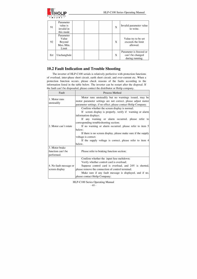
HLP-C100 Series Operating Manual
HLP-C100 Series Operating Manual - 65 -
91
Parameter value is
invalid in this mode
X Invalid parameter value to write.
92
Parameter Value
Beyond Max./Min.
Limit
X Value try to be set exceeds the limit
allowed.
Err Unchangbale X Parameter is freezed or
can’t be changed during running.
10.2 Fault Indication and Trouble Shooting The inverter of HLP-C100 serials is relatively perfective with protection functions
of overload, inter-phase short circuit, earth short circuit, and over-current etc. When a protection function occurs, please check reasons of the faults according to the information listed in the table below. The inverter can be restart after the disposal. If the fault can’t be disposaled, please contect the distributor or Holip company.
Fault Process Method
1. Motor runs unsteadily
Motor runs unsteadily but no warnings issued, may be motor parameter settings are not correct, please adjust motor parameter settings, if no effect, please contact Holip Company.
2. Motor can’t rotate
Confirm whether the screen display is normal; If screen display is properly, verify if warning or alarm
information displays; If any warning or alarm occurred, please refer to
corresponding troubleshooting section; If no warning or alarm occurred, please refer to item 5
below; If there is no screen display, please make sure if the supply
voltage is correct; If the supply voltage is correct, please refer to item 4
below. 3. Motor brake function can’t be performed.
Please refer to braking function section;
4. No fault message or screen display
Confirm whether the input fuse meltdown; Verify whether control card is overload; Suppose control card is overload, and 24V is shorted,
please remove the connection of control terminal; Make sure if any fault message is displayed, and if no,
please contact Holip Company;
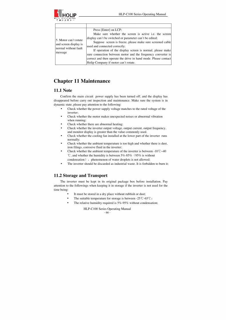
HLP-C100 Series Operating Manual
HLP-C100 Series Operating Manual - 66 -
5. Motor can’t rotate and screen display is normal without fault message
Press [Enter] on LCP; Make sure whether the screen is active i.e. the screen
display can’t be switched or parameter can’t be edited; Suppose screen is freeze, please make sure screened cable
used and connected correctly; If operation of the display screen is normal, please make
sure connection between motor and the frequency converter is correct and then operate the drive in hand mode. Please contact Holip Company if motor can’t rotate.
Chapter 11 Maintenance 11.1 Note
Confirm the main circuit power supply has been turned off, and the display has disappeared before carry out inspection and maintenance. Make sure the system is in dynamic state, please pay attention to the following:
• Check whether the power supply voltage matches to the rated voltage of the inverter;
• Check whether the motor makes unexpected noises or abnormal vibration when running;
• Check whether there are abnormal heating; • Check whether the inverter output voltage, output current, output frequency,
and monitor display is greater than the value commonly used. • Check whether the cooling fan installed at the lower part of the inverter runs
normally; • Check whether the ambient temperature is too high and whether there is dust,
iron filings, corrosive fluid in the inverter; • Check whether the ambient temperature of the inverter is between -10ć~40
ć, and whether the humidity is between 5%-85%˄95% is without condensation˅ˈphenomenon of water droplets is not allowed;
• The inverter should be discarded as industrial waste. It is forbidden to burn it;
11.2 Storage and Transport The inverter must be kept in its original package box before installation. Pay
attention to the followings when keeping it in storage if the inverter is not used for the time being:
• It must be stored in a dry place without rubbish or dust; • The suitable temperature for storage is between -25ć-65ć˗ • The relative humidity required is 5%-95% without condensation;

HLP-C100 Series Operating Manual
HLP-C100 Series Operating Manual - 67 -
• There is no corrosive gas or liquid in the storage ambience; • It is better to lay the inverter on a rack and keep it in a proper package; • The ambient temperature for transport is between -25ć-70ć˗ • The relative humidity of transport ambience must be less than 95%
˄Ambient temperature is 40ć˅. Attention: It is better not to store the inverter for long time. Long time storage of the
inverter will lead to the deterioration of electrolytic capacity. If it needs to be stored for a long time make sure to power it up one time within a year and the power-up time should be at least above five hours. When powering up, supply voltage must be increased slowly with a voltage regulator to the rated voltage value.
Chapter 12 Communication protocol HLP-C100 series inverter follows the standard Modbus RTU protocol.
12.1 Format specification Address Function code Data CRC
8 bits 8 bits N*8 bits 16 bits
1˅Address˖1-247
2˅Function˖HLP-C100 support following function code
01: Read Coil Status
03: Read Holding Registers
05: Force Single Coil
06: Preset Single Register
15: Force Multiple Coils
16: Preset Multiple Regs
3˅DATA˖Nh8bits
4˅CRC˖CRC check
12.2 Coil addressing Coil address R/W Description
0-15 RˈW Frequency converter control word (see following table)
16-31 RˈW Frequency converter speed or setpoint

HLP-C100 Series Operating Manual
HLP-C100 Series Operating Manual - 68 -
32-47 R Frequency converter status word(see following table)
48-63 R Frequency converter output frequency
64 W Parameter write control
0000-Parameter changes are written to the RAM˗
FF00- Parameter changes are written to the RAM and EEPROM˗
65-65535 Reserved
FC control word
Coil address
0 1
00 Preset reference bit0
01 Preset reference bit1
02 DC brake No DC brake
03 Coast stop No coast stop
04 Reserved
05 Freeze freq No freeze freq
06 Ramp stop Start
07 No reset Reset
08 No jog Jog
09 Ramp 1 Ramp 2
10 Data invalid Data valid
11 Relay off Relay on
12 Reserved
13 Reserved
14 Reserved
15 No reversing Reversing
Status word
Coil address
0 1
32 Control not ready Control ready

HLP-C100 Series Operating Manual
HLP-C100 Series Operating Manual - 69 -
33 Frequency converter not ready Frequency converter ready
34 Coasting stop Satety closed
35 No alarm Alarm
36 Reserved
37 Reserved
38 Reserved
39 No warning Warning
40 Not at reference At reference
41 Hand mode Auto mode
42 Out of freq range In freq range
43 Stopped Running
44 Reserved
45 No voltage warning Voltage warning
46 Not in current limit Current limit
47 No thermal warning Thermal warning
Register Description
00000-00007 Reserved
00008 Parameter index
00009-00989 Parameter group 00
00999-01989 Parameter group 01
01999-02989 Parameter group 02
Ă Ă
15999-16989 Parameter group 16
The relationship between register address and parameter number is: register address = parameter number × 10 -1
12.3 Read Coil Status Example˖Detect inverter output frequency
Transmit˖ 01 01 00 30 00 10 3D C9˄Hexadecimal˅

HLP-C100 Series Operating Manual
HLP-C100 Series Operating Manual - 70 -
Receive˖ 01 01 02 00 20 B8 24˄Hexadecimal˅
Transmit data
Field Description
01 FC address
01 Funtion
00 30 Coil address (ADDRH ADDRL)DŽ0x0030 convert to decimal number is 48. Coil address 49 is frequency converter output frequency.
00 10 Data bits number is 16. 0x 0010 convert to decimal number is 16
3D C9 CRC check
Receive data
Field Description
01 FC address
01 Function
02 The read byte number is 2
00 20 Ouput frequencyDŽSwap high and low, the data is 0x2000, so the output frequency is 50% of C03.03. Why does 0x2000 correspond to 50%, please see 12.6.
B8 24 CRC check
12.4 Read Holding Registers Example˖Read the value of C03.03
Transmit˖01 03 0B D5 00 02 D7 D7 ˄Hexadecimal˅
Receive˖ 01 03 04 00 00 EA 60 B5 7B˄Hexadecimal˅
Transmit data
Field Description
01 FC address
03 Function
0B D5 Register address(ADDRH ADDRL)DŽThe register address of C03.03 is 303*10-1=3029˄0x0BD5˅
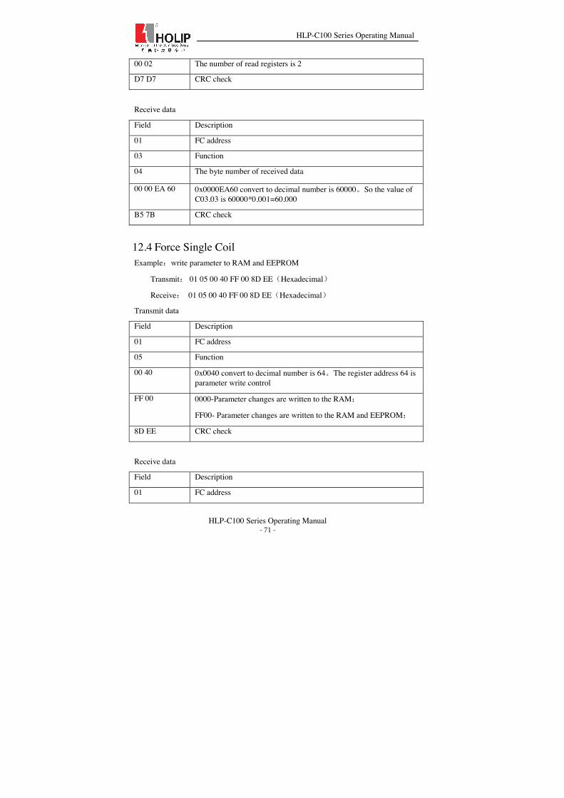
HLP-C100 Series Operating Manual
HLP-C100 Series Operating Manual - 71 -
00 02 The number of read registers is 2
D7 D7 CRC check
Receive data
Field Description
01 FC address
03 Function
04 The byte number of received data
00 00 EA 60 0x0000EA60 convert to decimal number is 60000DŽSo the value of C03.03 is 60000*0.001=60.000
B5 7B CRC check
12.4 Force Single Coil Example˖write parameter to RAM and EEPROM
Transmit˖ 01 05 00 40 FF 00 8D EE˄Hexadecimal˅
Receive˖ 01 05 00 40 FF 00 8D EE˄Hexadecimal˅
Transmit data
Field Description
01 FC address
05 Function
00 40 0x0040 convert to decimal number is 64DŽThe register address 64 is parameter write control
FF 00 0000-Parameter changes are written to the RAM˗
FF00- Parameter changes are written to the RAM and EEPROM˗
8D EE CRC check
Receive data
Field Description
01 FC address

HLP-C100 Series Operating Manual
HLP-C100 Series Operating Manual - 72 -
05 Function
00 40 0x0040 convert to decimal number is 64DŽThe register address 64 is parameter write control
FF 00 0000-Parameter changes are written to the RAM˗
FF00- Parameter changes are written to the RAM and EEPROM˗
8D EE CRC check
12.5 Preset Single Register Example˖set C01.01 = 1
Transmit˖01 06 03 F1 00 01 19 BD˄Hexadecimal˅
Receive˖ 01 06 03 F1 00 01 19 BD˄Hexadecimal˅
Transmit data
Field Description
01 FC address
06 Function
03 F1 The register address of C01.01 is 101*10-1=1009˄0x03F1˅
00 01 The parameter value is 1
19 BD CRC check
Receive data
Field Description
01 FC address
06 Function
03 F1 The register address of C01.01 is 101*10-1=1009˄0x03F1˅
00 01 The parameter value is 1
19 BD CRC check
12.6 Force Multiple Coils Example˖the frequency is 40% of C03.03.

HLP-C100 Series Operating Manual
HLP-C100 Series Operating Manual - 73 -
Transmit˖ 01 0F 00 00 00 20 04 7C 04 9A 19 37 B3˄Hexadecimal˅
Receive˖ 01 0F 00 00 00 20 54 13˄Hexadecimal˅
Transmit data
Field Description
01 FC address
0F Function
00 00 Register address 0 is frequency converter control word.
00 20 The bit number is 32.
04 The byte number is 4
7C 04 Control wordDŽĀ7C 04āswap high byte and low byte, the value is 0x047C
Note˖ 0x047C convertes to binary is˖0000 0100 0111 1100 are corresponding to the coil address 0-15
9A 19 Frequency reference.Ā9A 19ā swap high byte and low byte, the value is 0x199ADŽFrequency is 40% of C03.03(see the following frequency conversion specification).
37 B3 CRC check
Frequency conversion specification˖ If you want to set the frequency as 20Hz, 20Hz is 40% of the maximum frequency (it determined by the C03.03 parameters, the default is 50Hz). Calculation method: 20/50 * 16384 = 6553.6 converted to hexadecimal 0x199A. So if you want to set the frequency as feq, you can calculate: feq / C03.03 × 16384 then converts into hexadecimal. 16384 converts into hexadecimal is 0x4000. The reason to be multiplied 16384 is for a higher accuracy. Receive data
Field Description
01 FC address
0F Function
00 00 Register address 0 is frequency converter control word.
00 20 The bit number is 32.
54 13 CRC check

HLP-C100 Series Operating Manual
HLP-C100 Series Operating Manual - 74 -
12.7 Preset Multiple Regs Example˖Set C03.03 = 60.000
Transmit˖01 10 0B D5 00 02 04 00 00 EA 60 02 B4˄Hexadecimal˅
Receive˖ 01 10 0B D5 00 02 52 14˄Hexadecimal˅
Transmit data
Field Description
01 FC address
10 Function
0B D5 The register address of C03.03 is 303*10-1=3029˄0x0BD5˅
00 02 Register number
04 The byte number of data is 4
00 00 EA 60 0x0000EA60 convert to decimal number is 60000. So the value of C03.03 is 60000*0.001=60.000
02 B4 CRC check
Receive data
Field Description
01 FC address
10 Function
0B D5 The register address of C03.03 is 303*10-1=3029˄0x0BD5˅
00 02 Register number
52 14 CRC check
12.8 Read/Write array Example˖write parameter 310[2]˄index=2˅
Transmit˖01 06 00 08 00 02 89 C9 (Hexadecimal)
Receive˖ 01 06 00 08 00 02 89 C9 (Hexadecimal)
Transmit˖01 10 0C 1B 00 01 02 00 00 69 BB (Hexadecimal)
Receive˖ 01 10 0C 1B 00 01 72 9E (Hexadecimal)

HLP-C100 Series Operating Manual
HLP-C100 Series Operating Manual - 75 -
Transmit data 1
Field Description
01 FC address
06 Function
00 08 Register address˄ADDRH ADDRL˅ˈthe register address of parameter index is 0x0008
00 02 The index is 2(0x0002)
89 C9 CRC check
Receive data 1
Field Description
01 FC address
06 Function
00 08 Register address˄ADDRH ADDRL˅ˈthe register address of parameter index is 0x0008
00 02 The index is 2(0x0002)
89 C9 CRC check
Transmit data 2
Field Description
01 FC address
10 Function
0C 1B The register address of C03.10 is 310*10-1=3099˄0x0C1B˅
00 01 Register number
02 Byte number
00 00 The value of 310[2] is 0
69 BB CRC check
Receive data 2
Field Description
01 FC address

HLP-C100 Series Operating Manual
HLP-C100 Series Operating Manual - 76 -
10 Function
0C 1B The register address of C03.10 is 310*10-1=3099˄0x0C1B˅
00 01 The number of register
72 9E CRC check
12.9 Exception code When a communication exception is happened, the inverter returns data format as following˖
Address Function Exception code CRC check
8 bits 8 bits 8 bits 16 bits
Exception code Description
0x00 Parameter number does not exist
0x01 Defined parameters can not be written
0x02 The value exceeds the upper limit of the parameter
0x03 Index does not exist
0x04 The parameter is not array type
0x05 Data type exception
0x06 Only use for reset
0x07 Cannot be changed
0x0B Not allowed to write
0x11 Data cannot be changed in the current mode(some parameter cannot be changed when the inverter is running)
0x12 Other exception
0x40 Invalid data address
0x41 Invalid length
0x42 Invalid length and value
0x43 Invalid parameter
0x82 The parameters has no bus connection

HLP-C100 Series Operating Manual
HLP-C100 Series Operating Manual - 77 -
0x83 Factory settings, cannot be changed.
![HLP-B Series Operating Manual HLP-B Series English... · 7.3 Using digital in terminals to control the drive [AUTO] 149 7.4 Set-up selection 149 7.5 Potentiometer reference 150 7.6](https://img.dokumen.tips/doc/110x75/60356e0f5ea4f83ff0629f6c/hlp-b-series-operating-hlp-b-series-english-73-using-digital-in-terminals.jpg)