Embed Size (px)
Citation preview

CAMTECH/E/13-14/Check Points-TL/1.0
Handbook on Check Points for TL Coaches July, 2013
1
Hkkjr ljdkj GOVERNMENT OF INDIA jsy ea=ky;jsy ea=ky;jsy ea=ky;jsy ea=ky; MINISTRY OF RAILWAYS
egkjktiqjegkjktiqjegkjktiqjegkjktiqj, Xokfy;j & Xokfy;j & Xokfy;j & Xokfy;j & 474 005474 005474 005474 005 Maharajpur, GWALIOR - 474 005
CAMTECH/E/13-14/Check Points-TL/1.0
July 2013
dsoy dk;Zky;hu mi;ksx gsrq (For Official Use Only)
Handbook on CHECK POINTS Handbook on CHECK POINTS Handbook on CHECK POINTS Handbook on CHECK POINTS forforforfor
TL Coaches TL Coaches TL Coaches TL Coaches TARGET GROUP: TL Coaching Maintenance Staff

CAMTECH/E/13-14/Check Points-TL/1.0
July, 2013 Handbook on Check Points for TL Coaches
2
HHHHANDBOOK ONANDBOOK ONANDBOOK ONANDBOOK ON CHECKCHECKCHECKCHECK POINTSPOINTSPOINTSPOINTS FORFORFORFOR TLTLTLTL COACHESCOACHESCOACHESCOACHES
QUALITY POLICY
“To develop safe, modern and cost
effective Railway Technology
complying with Statutory and
Regulatory requirements, through
excellence in Research, Designs and
Standards and Continual
improvements in Quality
Management System to cater to
growing demand of passenger and
freight traffic on the railways”.

CAMTECH/E/13-14/Check Points-TL/1.0
Handbook on Check Points for TL Coaches July, 2013
3
FOREWORD
With increasing passenger traffic on Railways, coaching maintenance is a thrust area which requires proper and timely attention to provide comfortable and safe journey to our valued passengers.
In view of above CAMTECH has prepared this
handbook on “Check Points for TL Coaches” for electrical coaching maintenance staff which shall be useful in their day to day working.
CAMTECH, Gwalior A.R.Tupe Date: 31.07.2013 Executive Director

CAMTECH/E/13-14/Check Points-TL/1.0
July, 2013 Handbook on Check Points for TL Coaches
4
PREFACE
Proper attention during maintenance of TL coaches is essential to improve comfort level for the passengers and also to minimize enroute problems. CAMTECH has prepared this handbook on “Check Points for TL Coaches” which contains brief description of major under-frame and superstructure electrical equipment along with their maintenance. This also contains do’s and don’ts. It is clarified that this handbook does not supersede any existing provisions laid down by RDSO or Railway Board. The handbook is for guidance only and it is not a statutory document. I am thankful to all field personnel who have helped us in preparing this handbook. Technological up-gradation & learning is a continuous process. Hence feel free to write to us for any addition or modification in this handbook. We shall highly appreciate your contribution in this direction.
CAMTECH, Gwalior Peeyoosh Gupta Date: 30.07.2013 Jt. Director Electrical

CAMTECH/E/13-14/Check Points-TL/1.0
Handbook on Check Points for TL Coaches July, 2013
5
CONTENTS
Item No. Description Page No.
Foreword iii Preface v Contents vi Correction Slip viii
1.0 INTRODUCTION 01 1.1 Wiring Scheme 01
1.2 Under Frame Equipment 04 1.3 Super Structure Equipment 10
2.0 TRIP SCHEDULE 13 2.1 Alternator 13 2.2 Axle Pulley 14 2.3 Belts 15 2.4 Rectifier cum Regulator (RRU) 17 2.5 Battery Box 18 2.6 Earth Checking 22 2.7 Fans 23 2.8 Lighting 24 2.9 Wiring and Accessories 25 2.10 Mobile/Laptop charging points 26 2.11 FDBs (Fuse Distribution Board) 26
3.0 FORTNIGHTLY SCHEDULE 26 3.1 Battery 26
4.0 MONTHLY SCHEDULE 28 4.1 Alternators, Rectifier and Regulators 28 4.2 Axle Pulley 28 4.3 Batteries 29 4.4 Junction Box 30 4.5 Wiring And Accessories 30

CAMTECH/E/13-14/Check Points-TL/1.0
July, 2013 Handbook on Check Points for TL Coaches
6
Item No. Description Page No. 4.6 Fans 31 4.7 Carriage Lighting 31
4.8 Switches 32 4.9 Fuse Distribution Boards and Fuse Cut Outs 33 4.10 Emergency Feed Terminals (EFTS) 33 5.0 QUARTERLY SCHEDULES 33
5.1 Batteries 33 6.0 IOH (NINE MONTHLY SCHEDULES) 36 6.1 Alternators 36
6.2 Axle Pulley & Alternator Pulley 37 6.3 ‘V’ Belts 37 6.4 Rectifier Cum Regulator Unit (RRU/ ERRU) 38 6.5 Battery & Battery Box 39 6.6 Carriage Lighting 40 6.7 Fans 40
7.0 DO’S AND DON’ TS 41
7.1 Alternator 41 7.2 Rectifier cum Regulator 41 7.3 `V’ Belts 42
REFERENCES 44

CAMTECH/E/13-14/Check Points-TL/1.0
Handbook on Check Points for TL Coaches July, 2013
7
ISSUE OF CORRECTION SLIP
The correction slips to be issued in future for this handbook will be numbered as follows:
CAMTECH/E/13-14/Check Points-TL/1.0/ C.S. # XX date--- Where “XX” is the serial number of the concerned correction slip (starting from 01 onwards). CORRECTION SLIPS ISSUED
Sr. No. Date of
issue Page no. and Item no. modified
Remarks

CAMTECH/E/13-14/Check Points-TL/1.0
Handbook on Check Points for TL Coaches July, 2013
1
1.0 INTRODUCTION
Most of the conventional non-air conditioned BG coaches (ie. TL coaches) running on Indian Railways are Self Generation (SG) type coaches fitted with 4.5 kW alternators. These coaches have 110 V DC systems for fan & lights.
Each coach is provided with bogie mounted axle driven one brush less alternator of 4.5 kW with static rectifier-cum-regulator unit (RRU)/ Electronic rectifier-cum-regulator unit (ERRU), giving an output at 124 volts D.C.
1.1 Wiring Scheme
(Ref: Specification No. EL/TL/48 (Rev.1) –2005) The general schematic wiring diagram is illustrated in RDSO Drawing No. SKEL-3928 Alt. 2 which is to be followed. The lights are arranged in two circuits (L-I, L-II) and fans in one circuit-F, each controlled by a rotary switch. Each circuit of lights and fans is protected by HRC fuse which acts as back up protection in case of any short circuit fault, isolating the faulty circuit only.
The circuit L-1 have essential/emergency lighting circuit which also include all Lavatory lights, 50% of compartment lights, doorway lights, Night lights in all types of IInd Class coaches. The L-II light circuit feeds all the balance lights in the coach.
The size of HRC fuse will be as per the type of coach and the coach load, which will be governed by the particular specification of the coach. Re-wirable tinned copper fuses protect the branch circuits for lights and fans. These re-wirable fuses are located on a distribution fuse board. All branch circuits are protected by the fuses, both on negative and

CAMTECH/E/13-14/Check Points-TL/1.0
July, 2013 Handbook on Check Points for TL Coaches
2
positive sides. Ordinarily one fuse protects upto a maximum of 3 light points or 2 fans points. The grouping of negative wires is done in such a manner that the group load is within the capacity of the distribution fuse board and arrangements are identical on positive and negative sides.
110 V DC Train Lighting (TL) systems
MAIN RECTIFIER BRIDGE
FIELD RECTIFIER BRIDGE
VOLTAGE & CURRENTSENSOR
OVER VOLTAGE PROTECTION
FIELD CONTROL CIRCUIT
A1A2 A3
FIELD
REGULATOR
F +
F-
B-
B+
4.5 K.W. BRUSHLESS ALTERNATOR
RE
CT
I FIE
R R
EG
ULA
TO
R(1
25 V
)
1 20
AH
BA
TT
ER
Y
BC
T
R.SW R.SW R.SW
15A
6A
5PM-1 5PM-1
SN-1 SN-1
EF
T
EF
T
6A 6A
15A 15A 15A
ALTERNATOR – REGULATOR BLOCK DIAGRAM

CAMTECH/E/13-14/Check Points-TL/1.0
Handbook on Check Points for TL Coaches July, 2013
3
The positive & negative cable is segregated by running them in two separate conduits. The phase & field cables from alternator to terminal box and from terminal box to rectifier cum regulator should be run in flexible PVC conduits. The size of fuses at various locations is as given below:
Sho
rt
time
(60
sec)
ra
ting
of c
able
37A
148A
148A
325A
Min
imum
si
ze o
f ca
ble
prot
ecte
d fo
r sh
ort
circ
uit
7/0.
85
(4m
m²)
7/1.
7 (1
6 m
m²)
7/1.
7 (1
6 m
m²)
7/2.
52 (
35
mm
²)
60 S
ec.
Fus
ing/
tr
ippi
ng
circ
uit
13A
Non
-fu
sing
/ no
n tr
ippi
ng
Cur
rent
8A
Fus
e si
ze
ratin
g
6A
(0.2
0mm
) (3
5 S
WG
)
16A
HR
C
16A
HR
C
35A
HR
C
40A
HR
C
Fus
e lo
cati
on
DF
B
Junc
tion
B
ox
-do-
-do-
Bat
ter
y B
ox
Cir
cuit
fuse
Pos
itive
/ N
egat
ive
Bra
nch
fuse
LI, L
II &
F
an
SP
M-I
&
SP
M-I
I
Mai
n N
egat
ive
Bat
tery
fu
se
Sin
gle
batte
ry
S.
N.
1.
2.
3.
4.
5.

CAMTECH/E/13-14/Check Points-TL/1.0
July, 2013 Handbook on Check Points for TL Coaches
4
Colour Code:
For easy identification of the cables, the various circuits have colour code as indicated below: Paralleling main and fan positive cables …….… Red Light positive cables. …………………..… ……Yellow Fan negative cables ………………………..…… Black
All other negative cables except fan negatives … Blue 1.2 UNDER FRAME EQUIPMENT
1.2.1 Brushless Alternator
The inductor type Brushless alternator is an axle driven, power-generating machine with ‘V’ belt drive, mounted on the bogies of the coaches. These are designed as per spec. no. RDSO/PE/SPEC /TL/0054-2003 (Rev ‘0’) with amndt.1 &2. The standard ratings at the dc output terminals of the rectifying and regulating equipment are 4.5 kW, 37.5A, 120 Volts. It is driven by 4 Nos. ‘V’ belt coupled between the axle and the alternator pulley.
The Alternator with the help of static/electronic rectifier cum regulator unit regulates and rectifies the voltage which is used for:
i. Charging the coach batteries ii. To meet electrical load i.e. fans, lights, mobile charging
points etc. in the coach.
The alternator is suspended on bogie on suspension boss fitted with alternator pin. The suspension boss fitted with a renewable bush having bore dia of 32.5 mm + 0.20 mm and alternator pin of diameter 31.75 mm + 0.0 mm / -0.10 mm.
CAMTECH/E/13-14/Check Points-TL/1.0
Handbook on Check Points for TL Coaches July, 2013
5
The alternator is secured with safety chains (as per
RDSO Drg. SKEL 3934) to avoid dropping of it on track in case of any breakage during run.
1.2.2 Axle & Alternator Pulley & Belts
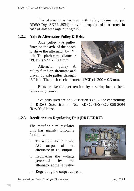
Axle pulley - A pulley fitted on the axle of the coach to drive the alternator by ‘V’ belt. The pitch circle diameter (PCD) is 572.6 ± 0.4 mm.
Alternator pulley A pulley fitted on alternator and driven by axle pulley through ‘V’ belt. The pitch circle diameter (PCD) is 200 ± 0.3 mm.
Belts are kept under tension by a spring-loaded belt-tensioning device.
‘V’ belts used are of ‘C’ section size C-122 conforming
to RDSO Specification No. RDSO/PE/SPEC/0059-2004 (Rev.’0’)/ latest.
1.2.3 Rectifier cum Regulating Unit (RRU/ERRU)
The rectifier cum regulator unit has mainly following functions:
i To rectify the 3 phase AC output of the alternator to DC output.
ii Regulating the voltage generated by the alternator at the set value.
iii Regulating the output current.

CAMTECH/E/13-14/Check Points-TL/1.0
July, 2013 Handbook on Check Points for TL Coaches
6
The static Rectifier cum Regulator (RRU) consists components Power rectifier, Magnetic Amplifier (MA), Excitation transformer (ET), Voltage detector (DT) and over volt protection relay (OVPR)
The Electronic Rectifier regulator unit (ERRU) employs IGBT with driver circuit for the control of field excitation. It employs Micro controller for the control of output DC voltage, out put current, Battery charging current and field current. Electronic Rectifier cum Regulator (ERRU) is as per RDSO specification No. RDSO/ PE/ SPEC/ D/AC/0013 (Rev.0).
1.2.3.1 Main features of ERRU with UVC (Universal Voltage Controller):
• Fast and reliable switching devices.
• Alternator identifying facilities
• Auto setting of parameters are such as output DC voltage, battery current, load current which in turn increase the life of battery and the alternator itself.
• Monitoring real time value of alternator voltage, load current, battery AH (IN), AH (OUT) etc., through interface fitted inside the coach.
1.2.3.2 Main advantages of ERRU:
• Control circuit is Modular type design.
• Auto identification of alternator is ratings and indications.
• Auto setting of parameters are of voltage, load current, Battery current, over voltage, over current and current limiting for all the regulator of 4.5 kW, 18 kW and 25 kW.
• UVC is interchangeable with all types of Electronic Regulators from 4.5 kW to 25 kW.

CAMTECH/E/13-14/Check Points-TL/1.0
Handbook on Check Points for TL Coaches July, 2013
7
• Close regulation of voltage +/- 2 V over the entire range of load and speed to have uniform charging of batteries.
• Less voltage and current ripple are on Battery Charging current.
• Controlled Battery charging current to have longer life of batteries.
• Moulded Hall sensors for current sensing and setting current limit.
• Static over voltage protection and latching without battery
• Isopack Power diodes directly mounted on the heat sinks to have better heat dissipation.
• Moulded PCBs to avoid dust and vibration problems.
• Separate interface unit for monitoring the parameters like DC Voltage, DC current, Battery charging and discharging currents, Amp, Hours etc. and it can be downloaded.
• This interface has facilities to store AH.IN and AH.OUT, generation and non-generation time, total distance traveled by coach and faults occurred in the regulators.
• This interface also has Emergency unit. In case of failure of one control unit, the other control unit will take care of both regulators.
1.2.3.3 Rating and Setting for 4.5 kW Regulator:
Rating: Voltage : 124 V Full Load amps : 38 A Speed Range : 550 RPM to 2500 RPM.

CAMTECH/E/13-14/Check Points-TL/1.0
July, 2013 Handbook on Check Points for TL Coaches
8
Setting: Normal : 124V +/- 0.5 V at 19 Amp. And at 1500 RPM Facility available for setting: 120V,122V & 124V Load Current : 42 Amp (Maximum)
Battery charging current : 24 Amp (Max.) 1.2.4 Batteries
In 110V, train lighting system, 6V, 120 Ah capacity mono block batteries are used in all types of conventional non air-conditioned BG coaches.
There are two types of batteries ie. Low maintenance lead acid (LMLA) and valve regulated lead acid (VRLA). Eighteen (18) Nos. mono-blocks (each consisting of 3 cell used in series) of battery constituting one set, are arranged in two battery boxes. In each battery box the mono-blocks are arranged in one row of 9 mono-blocks and each mono-block is kept perpendicular to the track. These are used in conjunction with brushless alternators with suitable rectifier cum regulator of 4.5 kW capacity with a nominal setting of 126 V, 37.5 Amp at full load and 1500 rev./ min.
1.2.4.1 Electrolyte: It shall be prepared from battery grade sulphuric
acid conforming to IS 266-1993 with latest amendment.
The level of electrolyte shall be at least 50 mm above the top of separator protector in fully topped up condition (up to the green level of float indicator).

CAMTECH/E/13-14/Check Points-TL/1.0
Handbook on Check Points for TL Coaches July, 2013
9
The specific gravity of electrolyte when the battery is in fully charged condition at 27 degree centigrade shall be between 1.210 to 1.220 for 120Ah. The specific gravity shall be corrected to 27 degree centigrade using the formula given under C1.3.2.2 of IS 8320-1982.
1.2.4.2 Water : The water used for topping up and preparing
electrolyte shall conform to IS 1069 – 1993.
1.2.4.3 Manufacturing & commissioning date of Battery: The year and month (e.g. April 12 can be shown as 04/12) of manufacturer shall be punched on positive terminal lug base with letter size not less than 6 mm height and on Negative terminal side commissioning of cells/batteries, month/year shall be marked by Railways.
1.2.5 Battery Box
It is suspended on
coach in the under-frame and is provided with front opening doors for paying attention to batteries. FRP trays are provided at the bottom to avoid corrosion of battery box from spillage of acid. The interior of the battery box is painted with anti-corrosive paint. The box is provided with ventilating grills to permit flow of outside air over the cells. A drain pipe is provided at the bottom of the box to allow spilled acid or water to drain out. Mild steel rods threaded at both ends are fixed to the battery boxes after loading the cells.
CAMTECH/E/13-14/Check Points-TL/1.0
July, 2013 Handbook on Check Points for TL Coaches
10
While mounting the battery box in under-frame of the coaches, special care is taken to provide locking nuts and split pins to avoid any accidental falling of batteries while running.
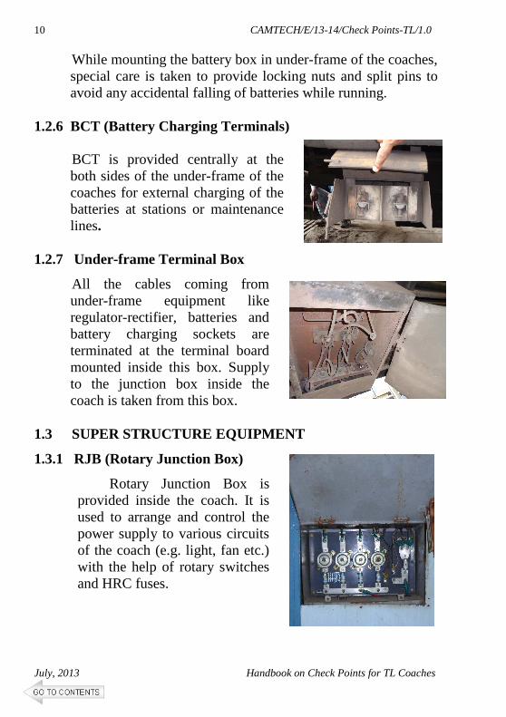
1.2.6 BCT (Battery Charging Terminals)
BCT is provided centrally at the both sides of the under-frame of the coaches for external charging of the batteries at stations or maintenance lines.
1.2.7 Under-frame Terminal Box
All the cables coming from under-frame equipment like regulator-rectifier, batteries and battery charging sockets are terminated at the terminal board mounted inside this box. Supply to the junction box inside the coach is taken from this box.
1.3 SUPER STRUCTURE EQUIPMENT
1.3.1 RJB (Rotary Junction Box)
Rotary Junction Box is provided inside the coach. It is used to arrange and control the power supply to various circuits of the coach (e.g. light, fan etc.) with the help of rotary switches and HRC fuses.

CAMTECH/E/13-14/Check Points-TL/1.0
Handbook on Check Points for TL Coaches July, 2013
11
1.3.2 EFT (Emergency Feed Terminals)
Each coach is provided with four emergency feed terminal boards on end panels, one each at the four corners of the coach at lower level to enable emergency connection to be made between adjacent coaches. On these terminal boards, the outer terminal shall be connected to the positive and the inner terminal shall be connected to negative.
1.3.3 Light Fittings
The coaches are fitted with FTL, CFL or incandescent light fittings. The fluorescent light fittings 2 feet long, 20 watt, CFL of 11w x 2, incandescent lamps 25w/40w are working on 110 V DC supply. Level of illumination (Ref: RDSO spec. no.EL/TL/48 (Rev’1’) –2005) The level of illumination to be attained in various types of coaches shall be as given below:

CAMTECH/E/13-14/Check Points-TL/1.0
July, 2013 Handbook on Check Points for TL Coaches
12
Class of coach Min. illumination level Ist class compartments 30 lux
2nd
class compartments 30 lux Postal compartments 40 lux Pantry compartments 30 lux Lavatories and corridor 16 lux Luggage compartment of SLR coaches 20 lux
1.3.4 Carriage Fans
On non AC BG coaches 400 mm sweep carriage fans are used where system voltage is 110 DC. These fans are fixed type with voltage range is 90- 140V DC.
These fans are being replaced with Brushless DC (BLDC) fans as per spec. no. RDSO/PE/SPEC/TL/0021/2005 (REV ‘1’) for 110 Volt dc, 400 mm and 450 mm sweep fixed type. The blades are made of fire retardant plastic material.
1.3.5 Fuse Distribution Boards (FDB)
Fuse distribution boards are provided for each compartment/ bay of the coach conforming to RDSO spec. no. RDSO/PE/SPEC/TL/0045 (Rev.0)-2003. The covers of Fuse distribution boards are modified vide RDSO

CAMTECH/E/13-14/Check Points-TL/1.0
Handbook on Check Points for TL Coaches July, 2013
13
modification sheet no. RDSO/ PE/ MS/ TL/ 0038-2006 (Rev.0) or latest to restrict the entry of waste/rubbish material inside the FDB through its cover and thus reduce the possibility of fires incidences in the cables in the vicinity of FDB.
2.0 TRIP SCHEDULE (Primary & Secondary Maintenance)
Attention on Maintenance Lines
Check the plate-form attention report and concentrate first on attending the defects in these coaches by adapting systematic trouble shooting procedures. Proceed as follows in respect of other equipment.
2.1 Alternator
• First attend alternators in coaches for generation, which have arrived "cold" and coach dark condition as per platform report. Proceed as follows:-
• Check field fuse, replace if found blown, with proper rating and approved make.
• Check the continuity of field and phase winding with the help of test lamp/ multi-meter to ensure that windings are not open circuited.
• Check for loss of residual magnetism with the help of voltmeter across the field terminals. In case of loss of magnetism, give 12 V DC flashing to the field terminals for few seconds to regain lost residual magnetism.
• Check that the regulator feedback loop is O.K.

CAMTECH/E/13-14/Check Points-TL/1.0
July, 2013 Handbook on Check Points for TL Coaches
14
• Check connections for tightness in alternator and rectifier regulator. If this is all right, remove belt from alternator.
• Use testing machine for testing alternator in situation. Couple the portable motor drive with Alternator.
• Check the DC output voltage at the rectifier and regulator terminals. Identify the defects if any and rectify them. The battery should be isolated while doing this test.
• Provide new split pin for pulley castle nut after completion of work.
• Check up the condition of safety chain and availability of split pins in safety chain bolts.
• Check up alternator suspension bracket and tension gear for any damage and replace, if necessary.
• Check up and tighten loose bolts in terminals box covers.
• Check availability of split pin for alternator castle nut.
• Never energize field from battery in case of failure of field circuit diode in regulator. Apart from non regulation, this may cause permanent damage to field windings.
• If there is no generation, ensure that there is no breakage in the cable termination.
2.2 Axle Pulley
• Examine the indicating white mark on the pulley axle and ensure that the pulley has not slipped. If pulley has slipped, take necessary corrective action.
• Tap the pulley with hammer and judge the tightness or crack by sound. If it gives clean metallic sound the pulley is tight. Dull sound indicates that it is loose. Bolt should be tightened with torque wrench to 30 kgm.
• Check the lock nuts and split pins for availability and tightness.

CAMTECH/E/13-14/Check Points-TL/1.0
Handbook on Check Points for TL Coaches July, 2013
15
2.3 Belts
• Check the belt tension after every round trip of the coach.
• For new V-belt fitted, the belt should be re-tightened after completing the first trip.
• Check condition of belt for fraying of edges, etc.,
• Check the belts for overturn and correct it, if necessary.
• Check the number of belts which should be 4 nos. for 4.5 kW alternators.
• Tension should be felt by hand by striking it slightly. Belt in correct tension will respond `alive' and `spring-back'. If required re-tensioning, the same shall be re-tensioned.
• Check that all the sets of belts provided should be of same make & grade.
2.3.1 Commissioning and checking of new ‘V’ belts (Ref. RDSO/PE/SMI/TL/0027-2004 (Rev. O) dt: 05.03.2004)
Whenever belts are replaced, to get optimum performance following precautions should be exercised:
a) The belts of same nominal length i.e. same grading should be used as a set.
b) Two or more makes of belts should not be used in a set.
c) Check tension of V belt after fitment by tension gauge.
d) Re-tension newly fitted belts after 1st trip or 500 km run, whichever is convenient.
e) Check alignment of pulleys whenever alternator is replaced.
f) Replace pulleys if grooves are worn out. Check by GO/NO-GO gauges.

CAMTECH/E/13-14/Check Points-TL/1.0
July, 2013 Handbook on Check Points for TL Coaches
16
To check the new ‘V’ belts for proper fitment, following gadgets should be available at each depot: (i) Pitch length of ‘V’ belt (ii) Angle of ‘V’ belt
(iii) Section of ‘V’ belt
Nominal circumference of pulley at pitch dia is 700 mm Nominal pitch length of the belt = 2E + 700 mm
19.0
+ 0.0322.53 - 0.00
34 ± 0.25
20
Outside dia 234.62 - 0.06 + 0.00
Normal pitch dia 222.8
E
FIXED PULLEY SLIDING PULLEY
F 76.5 kgf
SAMPLE BELT
Gadget to check Pitch length of ‘V’ belt

CAMTECH/E/13-14/Check Points-TL/1.0
Handbook on Check Points for TL Coaches July, 2013
17
Method of checking Angle of ‘V’ Belt Along a straight portion of the belt in an un-tensioned state, the cross-section shall be such that the edges of the broader (top) side of the belt shall touch the sides of V-groove having an included angle of 38 degree and the edges of the narrower (bottom) side of the belt shall touch the sides of V-groove having an included angle of 42 degree. The flanks of the belt shall not touch the sides of the V-grooves. 2.4 Rectifier cum Regulator (RRU)
• Clean regulator externally.
• Open regulator terminal cover and check for signs of overheating in all the terminals/bus bars/etc.
• Check up for loose connections and tighten the same. If the terminal board is found affected due to heat, replace terminal board with new one.
• Check for any damage to the phase and field wires /cables inter connecting regulator and alternator and its anchoring arrangement.
• Check and secure properly the terminal cover and regulator cover.
38°42°
Gauge for checking angle of v-belts

CAMTECH/E/13-14/Check Points-TL/1.0
July, 2013 Handbook on Check Points for TL Coaches
18
• Check the cable termination of the regulator visually for any abnormality.
• If the alternator arrived without generation, then open the regulator and check for any abnormality and ensure the fuses are intact.
• Check the cable for any abnormality from the alternator to the regulator by using test lamp, if found open/short, attend the same.
• If needed change the regulator and ensure the generation by running the alternator with a portable motor.
• Ensure that the settings of the alternator cum RRU/ERRU are as under (Ref: RDSO/PE/SMI/TL/0045-12/Rev.0 dated 13 June 2012)
Description Passenger / Express / Super fast
54 cells in Lead Acid & 57 cells battery bank (TL coaches fitted with VRLA batteries)
128.5 ± 0.5 Volts
Alternator voltage settings as mentioned above shall be made at half load i.e. 19A for TL coaches, at 1500 rpm.
2.5 Batteries/ Battery Box
i. Conventional Lead Acid Batteries
• To know the condition of cells during `Trip Examination' some cells in a battery are treated as `pilot' cells.
• On arrival of train in the maintenance line, disconnect all inter vehicle connections.
• Record the specific gravity of `pilot' cells in each battery.

CAMTECH/E/13-14/Check Points-TL/1.0
Handbook on Check Points for TL Coaches July, 2013
19
• Different cells should be identified as pilot cells every month. The idea of identifying different cells as pilot cells every month is to ensure that true condition of the battery is reflected.
• Marking of these cells to indicate pilot cells shall be done as follows and repeat cycle further
• Check the floats of each cell and check for correct electrolyte level as indicated in the float stem.
• Replace missing/defective floats.
• In case of low level, replenish with distill water.
• If any cell needs too much water for replenishing, watch for crack in the cells and also check the voltage on load which should not be less than 1.80V.
• In case of any defect, remove the mono-block and replace by a spare one preferably of the same make and lug date or a lug date as close to the one already in the coach.
• Coaches with discharged batteries which shows less than 100 V on load should be put on charge at double the normal rate of charge and the charging
1 2 3 4 5 6 7 8 9 10 11 12 13 14 15 16 17 18
Month Pilot Cells 1st Month 1, 12, 13 2nd Month 2, 11, 14 3rd Month 3, 10, 15 4th Month 4, 9, 16 5th Month 5, 8, 17 6th Month 6, 7, 18

CAMTECH/E/13-14/Check Points-TL/1.0
July, 2013 Handbook on Check Points for TL Coaches
20
reduced to half the rate of charge as soon as the gassing starts and continued till the specific gravity rises to the fully charged value which should be between 1210 and 1220.
• Use the battery charging terminals provided in coaches for charging purpose.
• Check up correct polarity and connect the charging cables.
• Use a clip on D.C. ammeter of 0-25 A range to check up the battery charging current. Note down the rate of charging and the number of hours of charge.
• Check specific gravity of pilot cells and the total voltage of battery on load at the end of charge and record.
• Keep micro porous vent plug tight.
• Ensure that washer is available in micro porous vent plugs.
• Check all the battery box members for any cracks in the fabricated battery box/cradle and take corrective action.
• Check for proper fitment of mono block in the battery box ensuring wooden packing pieces.
• The person in charge of battery maintenance should record all the readings mentioned above in his diary and this information should be transferred to the register maintained for various trains.
• Check anti-theft rods and provision of nuts both inside and outside the battery box on either side. Secure battery box cover finally after all works are completed.

CAMTECH/E/13-14/Check Points-TL/1.0
Handbook on Check Points for TL Coaches July, 2013
21
• Ensure that the fitment of the battery box is in order with all the bolts, nuts, lock nuts, split pins etc.
• Ensure the bottom plate of the box is well secured.
• Ensure the cells are properly cleaned.
• Ensure all micro porous vent plugs and sealed floats guide are properly closed.
• Check the terminations in the fuse and the condition of the fuse.
• Check the termination of cable in the under frame link box, for proper condition and attend if needed.
ii. VRLA Batteries:
(Ref. RDSO/PE/ SMI / TL /0024-2012/Rev.2 dated 17.08.2012)
(i) Check for by-passing of the failed cells. If the cells
are found by-passed, replace these failed cells immediately with the healthy ones.
(ii) Dust accumulation, if observed, clean with dry cotton cloth.
(iii) Cell cover/ container cracked or bursts, if noted, replace the cell with a healthy cell immediately.
(iv) In case of battery terminal/ cable over heating sign, check for loose connection at the cell terminal post/ cable end. If required, replace the cable immediately.
(v) Protective lid on safety valve if missing provide new one immediately.
(vi) Charge the batteries, preferably for 6-8 hrs. after arrival as cells may be partially discharged.
(vii) Do not boost charge the cells for more than 12 hours.
CAMTECH/E/13-14/Check Points-TL/1.0
July, 2013 Handbook on Check Points for TL Coaches
22
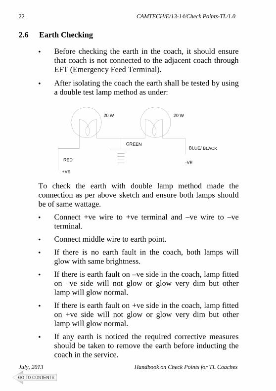
2.6 Earth Checking
• Before checking the earth in the coach, it should ensure that coach is not connected to the adjacent coach through EFT (Emergency Feed Terminal).
• After isolating the coach the earth shall be tested by using a double test lamp method as under:
To check the earth with double lamp method made the connection as per above sketch and ensure both lamps should be of same wattage.
• Connect +ve wire to +ve terminal and –ve wire to –ve terminal.
• Connect middle wire to earth point.
• If there is no earth fault in the coach, both lamps will glow with same brightness.
• If there is earth fault on –ve side in the coach, lamp fitted on –ve side will not glow or glow very dim but other lamp will glow normal.
• If there is earth fault on +ve side in the coach, lamp fitted on +ve side will not glow or glow very dim but other lamp will glow normal.
• If any earth is noticed the required corrective measures should be taken to remove the earth before inducting the coach in the service.
20 W 20 W
GREENBLUE/ BLACK
-VERED
+VE
CAMTECH/E/13-14/Check Points-TL/1.0
Handbook on Check Points for TL Coaches July, 2013
23
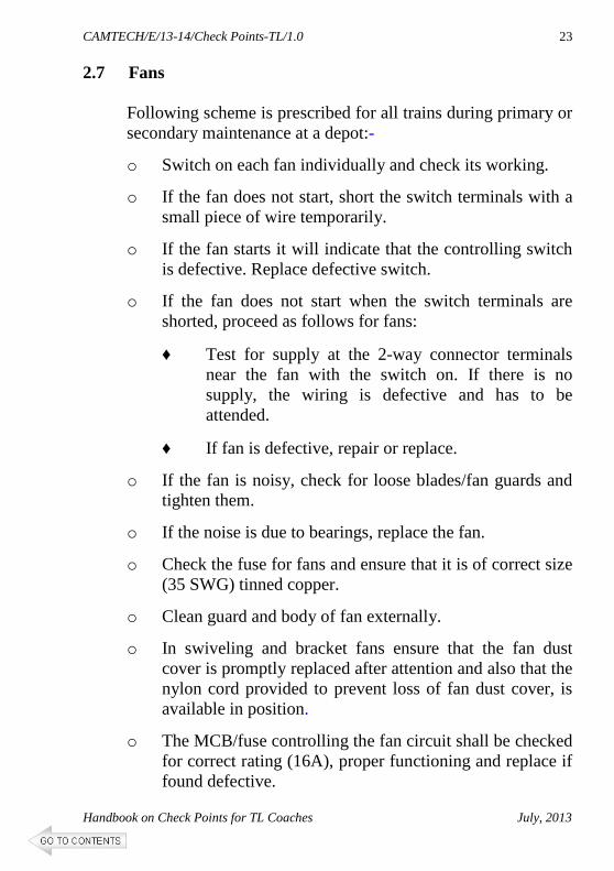
2.7 Fans
Following scheme is prescribed for all trains during primary or secondary maintenance at a depot:-
o Switch on each fan individually and check its working.
o If the fan does not start, short the switch terminals with a small piece of wire temporarily.
o If the fan starts it will indicate that the controlling switch is defective. Replace defective switch.
o If the fan does not start when the switch terminals are shorted, proceed as follows for fans:
♦ Test for supply at the 2-way connector terminals near the fan with the switch on. If there is no supply, the wiring is defective and has to be attended.
♦ If fan is defective, repair or replace.
o If the fan is noisy, check for loose blades/fan guards and tighten them.
o If the noise is due to bearings, replace the fan.
o Check the fuse for fans and ensure that it is of correct size (35 SWG) tinned copper.
o Clean guard and body of fan externally.
o In swiveling and bracket fans ensure that the fan dust cover is promptly replaced after attention and also that the nylon cord provided to prevent loss of fan dust cover, is available in position.
o The MCB/fuse controlling the fan circuit shall be checked for correct rating (16A), proper functioning and replace if found defective.

CAMTECH/E/13-14/Check Points-TL/1.0
July, 2013 Handbook on Check Points for TL Coaches
24
2.8 Lighting • Switch on each lamp/tube light/CFL. If the lamp/tube
light/CFL does not glow, check lamp/tube light /CFL and replace, if fused.
• If the lamp/tube light/CFL is all right, check control fuse and replace, if found blown.
• If the fuse is all right, check control switch and replace, if necessary.
• If the switch is all right, check up lamp holder for any defect or loose connection and rectify.
• If there is no defect in the lamp holder, check up for supply at the holder terminals and if the wiring is found defective, rectify.
• Provide switch covers and fuse covers promptly, if they are missing.
• If any dome cover is open or not secured properly, rectify defect, if any and secure.
• Replace broken glass domes/acrylic covers of tube lights/CFLs.
• Check MCBs/fuses for light circuits in junction box for proper operation and replace defective MCBs. Check for loose connections between MCB and bus bars and rectify.
• Ensure that MCBs/fuses are intact for protection of each circuit.
• Check tightness of terminal connections of HRC fuse for negative circuit in junction box.
• Never by-pass or use incorrect fuses as this may result in serious failures.

CAMTECH/E/13-14/Check Points-TL/1.0
Handbook on Check Points for TL Coaches July, 2013
25
2.9 Wiring and Accessories
• Earthing of wiring in the coach shall be checked both on the positive and negative wire separately in each coach by the earth testing device.
• A coach with negative earth fault in case of 110 V DC systems, which could not be attended in time, can be given in service in case of emergency. The coach shall be taken for attention by the primary maintenance station during the next trip.
• Testing shall be done only at cable terminations.
• Poor crimping of cable lugs and loose connections in terminals may result in excessive heating and discoloration of lugs, tapes and cables. Check for this during inspection and take prompt action to locate and rectify the defects.
• Replace incorrect size of HRC fuses by correct rating.
• Check all fuses and ensure that they are secured tightly to their terminals. Replace defective MCBs/fuses in junction box by MCBs/fuses of correct rating.
• Remember that fuses are provided for protecting circuits in case of faults. Try to find out the cause of fault.
• Loose and exposed/hanging wires should be secured and properly covered.
• In case wiring is found mechanically damaged or tampered with or needs replacement, the coach should be marked electrically “sick”. If the work is of a minor nature, this may be done in maintenance lines.
• Coaches which are suspected to have wiring defect either in the under-frame or roof shall be subjected to insulation test with 500 V megger.

CAMTECH/E/13-14/Check Points-TL/1.0
July, 2013 Handbook on Check Points for TL Coaches
26
Record all the attention given in the under frame and roof, the Specific Gravity, the condition of generation, lamps, fans and fuses, availability of belts etc. with coach and other details.
2.10 Mobile/Laptop charging point
Check and ensure supply and functioning of each Mobile/Laptop charging point, replace if found defective.
2.11 FDBs (Fuse Distribution Board)
Check FDB’s cover for any gap and entry for waste/rubbish material.
3.0 FORTNIGHTLY SCHEDULE In addition to the instructions contained under "Trip examination" the following works shall be carried out: 3.1 Battery
� Clean the interior of battery box.
• Clean the cell tops and deposit of sulphation, if any in inter cell and end cell connections.
• Remove sulphated inter cell connections, clean the connecting surface with a piece of cloth.
• Use fresh fasteners.
• Sulphated internal connections and fasteners should be soaked in kerosene oil, cleaned with warm water and kept ready for use.
• Inter cell connections should be provided with both small and large strips and four fasteners each with one hexagonal nut, one spring washer to IS:3063 and two steel punched washers to IS:2016.
• Remove end cell connectors, clean the connecting surface both in cell and connector thoroughly and provide back.
CAMTECH/E/13-14/Check Points-TL/1.0
Handbook on Check Points for TL Coaches July, 2013
27
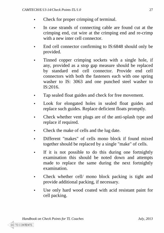
• Check for proper crimping of terminal.
• In case strands of connecting cable are found cut at the crimping end, cut wire at the crimping end and re-crimp with a new inter cell connector.
• End cell connector confirming to IS:6848 should only be provided.
• Tinned copper crimping sockets with a single hole, if any, provided as a stop gap measure should be replaced by standard end cell connector. Provide end cell connectors with both the fasteners each with one spring washer to IS: 3063 and one punched steel washer to IS:2016.
• Tap sealed float guides and check for free movement.
• Look for elongated holes in sealed float guides and replace such guides. Replace deficient floats promptly.
• Check whether vent plugs are of the anti-splash type and replace if required.
• Check the make of cells and the lug date.
• Different "makes" of cells mono block if found mixed together should be replaced by a single "make" of cells.
• If it is not possible to do this during one fortnightly examination this should be noted down and attempts made to replace the same during the next fortnightly examination.
• Check whether cell/ mono block packing is tight and provide additional packing, if necessary.
• Use only hard wood coated with acid resistant paint for cell packing.
CAMTECH/E/13-14/Check Points-TL/1.0
July, 2013 Handbook on Check Points for TL Coaches
28
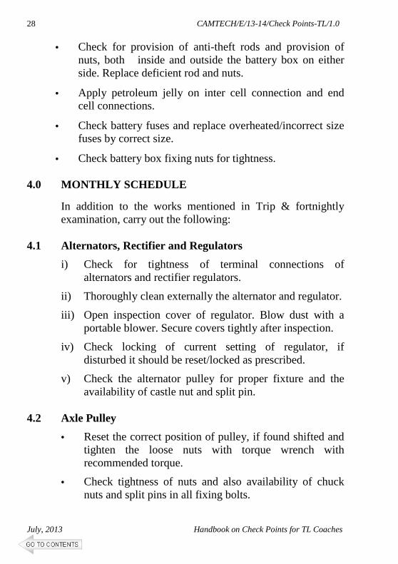
• Check for provision of anti-theft rods and provision of nuts, both inside and outside the battery box on either side. Replace deficient rod and nuts.
• Apply petroleum jelly on inter cell connection and end cell connections.
• Check battery fuses and replace overheated/incorrect size fuses by correct size.
• Check battery box fixing nuts for tightness. 4.0 MONTHLY SCHEDULE
In addition to the works mentioned in Trip & fortnightly examination, carry out the following:
4.1 Alternators, Rectifier and Regulators
i) Check for tightness of terminal connections of alternators and rectifier regulators.
ii) Thoroughly clean externally the alternator and regulator.
iii) Open inspection cover of regulator. Blow dust with a portable blower. Secure covers tightly after inspection.
iv) Check locking of current setting of regulator, if disturbed it should be reset/locked as prescribed.
v) Check the alternator pulley for proper fixture and the availability of castle nut and split pin.
4.2 Axle Pulley
• Reset the correct position of pulley, if found shifted and tighten the loose nuts with torque wrench with recommended torque.
• Check tightness of nuts and also availability of chuck nuts and split pins in all fixing bolts.

CAMTECH/E/13-14/Check Points-TL/1.0
Handbook on Check Points for TL Coaches July, 2013
29
4.3 Batteries Conventional Lead Acid Batteries
Record specific gravity of individual cells/mono block.
• "Switch on" full load of the coach and record individual voltage of cells and total voltage.
• "Switch off" load. If the specific gravity is less than that painted on the battery box, charge the cells as specified under "Trip Examination" after topping up with DM water, if required.
• Use battery charging terminals provided on coaches for charging purposes.
• Charging should be continued till the specific gravity rises to the value of mentioned in battery box, on "Pilot" cells.
• In case pilot cells show no appreciable improvement, check specific gravity of adjacent cells. If the specific gravity does not improve in spite of charging, replace the battery by another set.
• Cells should be handled with due care while unloading and in transit to avoid breakage.
• On completion of charging, record the specific gravity of individual cells. If there is any wide variation in the specific gravity/ voltage of cells, disconnect and replace those cells showing low specific gravity/voltage by spare ones.
• In case there are more than 1/3 of total cells with low specific gravity, the entire set should be replaced.
• Cells showing reverse voltage, zero volts should be withdrawn and replaced by charged cells immediately.

CAMTECH/E/13-14/Check Points-TL/1.0
July, 2013 Handbook on Check Points for TL Coaches
30
• Record individual voltage of cells and the total voltage on full load of the coach.
• Change the marking of the pilot cell as given in trip schedule.
4.4 Junction Box
• Open front door. Check all connections in MCB-cum-
fuse panel for tightness any for heating sign, fuses etc.
• Check availability of terminal lugs for all cables in junction box and replace if necessary by terminal lugs of correct size.
• Check rotary switches / MCBs provided for lights, fans circuits for correct condition and rotary switch and EFTs for proper operation.
• Replace/ repair defective MCBs.
• Check up negative fuse and replace, if necessary by correct ratings of HRC fuse.
• If rotary switches are provided instead of MCBs, Check for proper operation.
• Check up HRC fuses provided with rotary switches for correct rating and replace, if necessary.
• Close front door and secure properly by the locking key, If found defective, the same may be attended/replaced.
4.5 Wiring and Accessories
• Superstructure wiring and under-frame wiring shall be tested separately for which the main negative fuse in shall be opened and controlling MCBs for all circuits kept off.

CAMTECH/E/13-14/Check Points-TL/1.0
Handbook on Check Points for TL Coaches July, 2013
31
• All other fuses shall remain in circuit.
• Insulation resistance shall be measured with all fittings and equipment connected both on under-frame and superstructure.
• The under-frame wiring shall be tested with battery fuse open.
• The IR value should be minimum 2 Mega-Ohm in fair weather condition and minimum 1 Mega-Ohm under adverse weather condition.
• Availability of inspection cover of DFBs should be ensured.
4.6 Fans
• The fan body, guards and blade shall be thoroughly cleaned with cloth.
• All fans shall be opened and condition of commutator, brushes and brush gear shall be thoroughly checked.
• Studs used for fixing the fan to coach body, shall be checked and tightened, wherever necessary.
• Availability of all the three fixing studs should be ensured.
• All the switches controlling the fans shall be checked for its smooth operation and correct working and replaced, where necessary.
• Fan blades shall be replaced if found bent, or if there is no proper air discharge.
4.7 Carriage Lighting
• Open each fitting with the dome key and remove the dust of the fitting both from inside and outside.

CAMTECH/E/13-14/Check Points-TL/1.0
July, 2013 Handbook on Check Points for TL Coaches
32
• Ensure free operation of locking mechanism and replace defective fitting.
• Clean first glass domes with wet cloth and then with a clean dry cloth.
• Replace rusted fittings and fittings with damaged surface.
• Check up wattage of lamps and replace with that of correct wattage.
• Check up whether toggle switches are marked to indicate lighting control "L", night light control `NL', side lamps in guards compartment as `SL', tail lamps as `TL-Rear', `TL-Front', luggage room as `LRL'.If not, stencil legends with fluorescent paint.
• Check up all lighting circuit fuses in each coach for correct size and replace if necessary.
• Stencil the size of fuses near the locations, if not already done.
• Mark inspection covers of distribution fuse boards as `DFB' if not done already.
• Thoroughly clean metal guards for roof light fittings in luggage rooms and paint, if necessary.
4.8 Switches
• Check each switch of lights and fans for proper fixing
and operation. Replace defective switches. • Switches should be provided in the locations intended
for them and provided with covers with their knobs exposed for operation by passengers.

CAMTECH/E/13-14/Check Points-TL/1.0
Handbook on Check Points for TL Coaches July, 2013
33
4.9 FDBs Fuse Distribution Boards Check distribution fuse boards and fuse cut outs of light and fan circuits, for over heating and tightness of connections and provisions of correct size of fuses in the fuse terminals.
4.10 Emergency Feed Terminals (EFTs) • Check up supply and marking of polarity of EFTs. • Replace missing EFTs and those without wiring nuts.
5.0 QUARTERLY SCHEDULES
In addition to the instructions contained under "Monthly Examination" following activities should be done:
5.1 Batteries
i. Conventional Lead Acid Batteries
• `Switch off’ load. Charge the cells at 50% of normal rate of charge, i.e., at 1/10th of the rated capacity of cells.
• Record hourly cell voltage and specific gravity reading of every cell.
• Terminate charging when 3 successive readings are constant.
• Record specific gravity and no load voltage of each cell 10 minutes after terminating charge.
• Specific gravity should be between 1.210 and 1.220 for cells upto 120 Ah capacity. The voltage should not be less than 2.1 V.

CAMTECH/E/13-14/Check Points-TL/1.0
July, 2013 Handbook on Check Points for TL Coaches
34
• If there is a wide variation in the specific gravity and voltage readings, such cells should be replaced.
• Check the cell voltage on full load.
• Cells showing reverse and low voltage are to be replaced with healthy cells of the same make/type.
ii. VRLA Batteries
(Ref. RDSO/PE/SMI/TL/0024-2012/Rev.2 dated 17.08.2012)
A. The following physical checks shall be made
(i) 13 Nm tightening torque of terminal bolt with torque wrench for four terminal design cell (all makes except Exide).
(ii) 22Nm tightening torque of terminal bolt with torque wrench for four terminal design cell (Exide).
(iii) Do not over tight.
(iv) Terminal post corrosion, if observed remove the cable and clean the terminal post and cable lug with brass brush or fine emery paper and apply petroleum jelly.
B. Check the open circuit voltage
a. If the total battery bank open circuit voltage for TL coaches is 117.0 Volts or above for 57 Cells.
The following steps shall be followed:
(i) Discharge the battery bank with full coach load for 15 minutes (based on coach arrival battery SOC).

CAMTECH/E/13-14/Check Points-TL/1.0
Handbook on Check Points for TL Coaches July, 2013
35
(ii) Note down the individual cell readings after 15 minutes while the coach is still connected during the discharge.
(iii) If all the cell voltages are 1.98 Volts and above then the cells are in healthy condition. Charge the cells same to be put back into service.
(iv) If some of the cell voltages are less than 1.98 Volts then give boost charging with 2.30 VPC for 12 hrs. by charging them separately with current limited to 20% of battery rated capacity
(v) The weak cells, which are charged separately, must be checked through a discharge at C-10 rate for 30 minutes, the end of discharge voltage should be above 2.0 V. If such a re-charged cell fails to qualify the above test, it should not be put back in the coach.
(vi) After performing the discharge test on the revived cells, the cells need to be charged at least for 4 hours, prior to fitment in the coach.
b. If the total battery bank, open circuit voltage for
TL coaches is less than 117.0 Volts for 57 Cells.
Charge the cells for 12 hrs with 2.30 VPC and then carry out the discharge test as per item no. i to iii of (a) above.

CAMTECH/E/13-14/Check Points-TL/1.0
July, 2013 Handbook on Check Points for TL Coaches
36
6.0 IOH (NINE MONTHLY SCHEDULE)
In addition to the instructions contained under "Quarterly Examination" following activities should be done:
6.1 Alternators
� Carry out visual inspection of terminal box for signs of overheating, fumes and presence of water etc., clean it.
� Check the connections for any defect, if required re-crimping and taping should be done. Replace spring washers, if overlapping.
� Disconnect the regulator and measure the insulation by 500 V megger; if found less than 10 M-ohm, remove alternator and heat its winding in the oven at 80 degree C for 1 hour.
• Check the condition of outgoing cables and its cleating arrangement. Replace the grommet, if necessary. Ensure that flexible pipe carrying the cables is connected properly to the grommet to prevent damage to insulation.
• Check the suspension pin, main suspension lugs of alternator and bogie brackets for any signs of crack. Provide new nylon bushes and secure nuts and bolts, with new split pins. Play between alternator lugs and bogie bracket should not be more than 4.0 mm.
• Check profile of ‘V’ groove for worn out pulley as per SMI No. RDSO/PE/SMI/TL/0030-2005 (Rev.0) dtd. 12.08.2005.
• Check the pulley fixing, concentrating on lock nut and locking collar pin. If lock nut is damaged, replace it.

CAMTECH/E/13-14/Check Points-TL/1.0
Handbook on Check Points for TL Coaches July, 2013
37
• Check safety chains and chain fixing nuts, bolts and split pins.
• Replace tension rod sleeve. Fit tension rod fixing pin of alternator with new washer and split pin. Replace spring, if belts loose upon coach arrival.
• Lubricate the threads of the tension rod and adjusting nut.
6.2 Axle Pulley & Alternator Pulley
• Check the lock nuts and split pins for availability and tightness. Appropriate open jaw type torque wrench to be used for uniform tightness of all studs, value of torque depends on the gap required between two pulley halves.
• Check distance between wheel hub and axle pulley with gauge plate.
• Check the condition of pulleys and its ‘V’ grooves profile as per SMI No. RDSO/PE/SMI/TL/0030-2005 (Rev.0) dtd. 12.08.2005. Replace the pulley, if required.
• Tap with hammer and judge the tightness by sound.
• Ensure gap between the two halves of the axle pulley is 3.0 ± 0.5mm.
• Examine the indicating white mark on the axle pulley and ensure that the pulley has not shifted. If pulley found shifted, remove the pulley and re-tighten it after replacing rubber pads and provide indicating white mark.
6.3 ‘V’ Belts
• Replace all existing “V” belts with new “V” belts having same grade/make. Follow the instruction given in SMI

CAMTECH/E/13-14/Check Points-TL/1.0
July, 2013 Handbook on Check Points for TL Coaches
38
No. RDSO/PE/SMI/TL/0027-2004 (Rev.0) dtd. 05.03.2004 for checking new “V” belts. The old “V” belts removed from service to be destroyed.
• Check tension of “V” belts. For the exact measurement of tension, a weight of 4 kg. shall be hanged from the centre of belt span and see that the top surface of this belt does not go below bottom surface of remaining belts. (Ref: RDSO letter no. EL/7.1.38/1 dated 24.01.2011 on Revised guidelines for tightening of V-belts)
6.4 Rectifier cum Regulator Unit (RRU/ ERRU)
• Clean regulator box externally and remove all the dust with dry compressed air.
• Open cover and change sealing sponge rubber gasket.
• Clean all dust with soft brush and vacuum cleaner from inside, particularly from heat sink of electronic components and terminal board.
• Check voltage and current setting. Ensure that they have not been disturbed and are in locked position. Following tests shall be done to ensure proper working of RRU/ ERRU with alternator:
• Set specified voltage 128.5 +/- 0.5 at half load 19 A & 1500 rpm.
• Check OVP set voltage and working. Check the proper suspension of the unit and provide new split pin in its suspension bolt.
• Tighten all the electrical connections and check whether power connections are provided with locking washers.
• Check field and phase HRC fuses for their proper rating and fitment.

CAMTECH/E/13-14/Check Points-TL/1.0
Handbook on Check Points for TL Coaches July, 2013
39
6.5 Battery & Battery Box
(i) Lead Acid Batteries
• Clean the battery box externally and remove all dust with dry compressed air.
• Open battery box covers. Remove inter-cell connections and take out the cells.
• Clean the cells, inter-cell and end cell connectors thoroughly. Replace spring washers, if each are overlapping.
• Check for crack in cell containers leading to leakage. If needed, replace the defective cell with healthy cell of similar capacity, make and lug date.
• Check for heating signs on the positive and negative terminals and discolouring of the cells container/ top lid. Clean the sulphation of terminals.
• Check the level of electrolyte in all the cells and top up with distilled water, if necessary.
• Check the specific gravity and voltage of all cells with cell tester.
• Check all vent plugs and float guides conditions and replace defective ones.
• Check the conditions of connecting strips/ leads and replace if required.
• Check all suspension bolts of battery box suspension/ cradle for signs of any crack, corrosion, rusting and take corrective action.
• Clean and examine condition of battery boxes.
• Examine condition of FRP tray and replace if necessary.
CAMTECH/E/13-14/Check Points-TL/1.0
July, 2013 Handbook on Check Points for TL Coaches
40
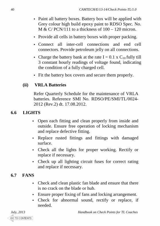
• Paint all battery boxes. Battery box will be applied with Grey colour high build epoxy paint to RDSO Spec. No. M & C/ PCN/111 to a thickness of 100 – 120 micron.
• Provide all cells in battery boxes with proper packing.
• Connect all inter-cell connections and end cell connectors. Provide petroleum jelly on all connections.
• Charge the battery bank at the rate I = 0.1 x C10 fully till 3 constant hourly readings of voltage found, indicating the condition of a fully charged cell.
• Fit the battery box covers and secure them properly.
(ii) VRLA Batteries
Refer Quarterly Schedule for the maintenance of VRLA batteries. Reference SMI No. RDSO/PE/SMI/TL/0024-2012 (Rev.2) dt. 17.08.2012.
6.6 LIGHTS
• Open each fitting and clean properly from inside and outside. Ensure free operation of locking mechanism and replace defective fitting.
• Replace rusted fittings and fittings with damaged surface.
• Check all the lights for proper working. Rectify or replace if necessary.
• Check up all lighting circuit fuses for correct rating and replace if necessary.
6.7 FANS
• Check and clean plastic fan blade and ensure that there is no crack on the blade or hub.
• Ensure proper fixing of fans and locking arrangement.
• Check for abnormal sound, rectify or replace, if needed.

CAMTECH/E/13-14/Check Points-TL/1.0
Handbook on Check Points for TL Coaches July, 2013
41
7.0 DO’S AND DON’TS
7.1 Alternator
i. Do’s
• Ensure that the correct polarity of field winding i.e. positive connected to F+ while measuring the continuity of the field winding, otherwise the alternator will not self excite.
• Check the proper compression force on the tensioning spring with indicator plate by tightening the special nut.
• Keep the terminal box tightly closed.
• Use the cable grommets or cable gland of correct size for reducing the vibration of terminal connections.
• It is preferable to anchor the cables externally to avoid shocks and vibrations on the terminals.
ii. Don’ts
• Don’t use improper tools to handle the alternator; it may damage parts of the alternator.
• Don’t re-grease the bearing frequently. Re-greasing should be done after thoroughly cleaning the bearing with white spirit. It is preferable to re-grease the bearing only during POH.
• Don’t keep the belts in over tension as this may reduce life of the belt.
7.2 Rectifier cum Regulator
i. Do’s
• Short all seven terminals of the terminal box before measuring the insulation resistance.

CAMTECH/E/13-14/Check Points-TL/1.0
July, 2013 Handbook on Check Points for TL Coaches
42
• Ensure that DC ‘+’ and DC ‘-’ are connected to battery positive and battery negative respectively. Wrong connection will damage main diodes.
ii. Don’ts
• Don’t disturb the settings of the regulator shunt and potentiometer.
• In any circumstances the burden resistance setting should not be disturbed.
• Don’t open the regulator box unless there is a defect.
• Don’t use a megger to test the components. Use multimeter.
• Don’t reverse the field terminals on regulator and alternator.
• Never use a fuse wire for field fuse. Always use HRC fuse of specified value.
7.3 `V’ Belts
i. Do’s
• Use belt of the same lengths for a set.
• Belts should be stocked in lots as per date of receipt and use in the principle of first in first out basis. The belts shall be stored in a well ventilated room free from direct sunlight and moisture.
• Re-tension newly fitted belts after first trip.
• Maintain a gap of approx. 55 mm between supporting plate and fixing nut on the free end of tension rod or upto the split pin for the 4.5 kW alternators.
• Maintain proper alignment between axle pulley and alternator pulley.

CAMTECH/E/13-14/Check Points-TL/1.0
Handbook on Check Points for TL Coaches July, 2013
43
ii. Don’ts
• Do not allow loose belts.
• Do not disturb the nut and check-nut on free end of tension rod if proper gap is available between supporting plate and fixing nut i.e. 55 mm for TL alternator.
• Do not use repaired pulleys.
• Do not use old and new mixed belts in sets.
• Belt should not have any oil or grease traces, if persist clean it by soap and water.
• The matched set should have belts of one manufacturer only. Do not use belt of same grade of different manufacturer in a set.
CAMTECH/E/13-14/Check Points-TL/1.0
July, 2013 Handbook on Check Points for TL Coaches
44
REFERENCES
1. Maintenance manual for BG Coaches of ICF Design issued by CAMTECH, July 2002.
2. Enhancement of POH Interval from 12 to 18 Months for ICF Design Coaches, January 2008 issued by CAMTECH.
3. System Specification and Code of Practice for Wiring for 110V DC Self Generation Train Lighting System, RDSO No. EL/TL/48 Rev. 1, 2005.
4. RDSO SMI No. RDSO/PE/SMI/TL/0045-12 Rev.0 dtd. June 2012.
5. RDSO SMI No. RDSO/PE/SMI/TL/0024-2012 Rev.2 dtd. August 2012.
6. RDSO SMI No. RDSO/PE/SMI/TL/0027-2004 Rev.0 dtd. 05.03.2004.
7. RDSO letter no. EL/7.1.38/1 dated 24.01.2011 on Revised guidelines for tightening of V-belts.
8. RDSO SMI No. RDSO/PE/SMI/TL/0030-2005 Rev.0 dtd. 12.08.2005.
*****

CAMTECH/E/13-14/Check Points-TL/1.0
Handbook on Check Points for TL Coaches July, 2013
45
If you have any suggestions and specific comments please write to us.
Contact person Director Electrical
Postal address Indian Railways
Centre for Advanced Maintenance Technology, Maharajpur, Gwalior,
Pin Code - 474 005
Phone 0751 – 2470740
0751 – 2470803
Fax
0751 – 2470841
OUR OBJECTIVE
To upgrade maintenance technologies and
methodologies and achieve improvement in productivity and performance of all Railway assets and manpower which inter-alia would cover reliability, availability, utilisation and
efficiency.


![Hkkjr ljdkj - DCMSME · Hkkjr ljdkj fodkl vk;qDr lw{e] y?kq ,oa eË;e m|e Hkkjr ljdkj fuekZ.k Hkou] ubZ fnYyh&110108 fn'kkfunsZ'k xq.koŸkk izcaËku ekudksa vkSj xq.koŸkk izkS|ksfxdh](https://img.dokumen.tips/doc/110x75/5b4efeb47f8b9a1b6e8b55a6/hkkjr-ljdkj-hkkjr-ljdkj-fodkl-vkqdr-lwe-ykq-oa-eee-me-hkkjr-ljdkj.jpg)


![cine rules 1983 - Central Board of Film Certification · Hkkjr ljdkj Hkkjr ljdkj lwpuk vkSj izlkj.k e=ky; lwpuk vkSj izlkj.k e=ky; pyfp= (izek.ku) fu;e]1983 fu;e]1983 {24 ekpZ]1992](https://img.dokumen.tips/doc/110x75/5f27cb4f57d21525eb6e610a/cine-rules-1983-central-board-of-film-certification-hkkjr-ljdkj-hkkjr-ljdkj-lwpuk.jpg)


![TRACTION INSTALLATION DIRECTORATE dkZ.k … · TRACTION INSTALLATION DIRECTORATE d"kZ.k laLFkkiu funs'kky; GOVERNMENT OF INDIA MINISTRY OF RAILWAYS Hkkjr ljdkj] jsy ea=ky; TECHNICAL](https://img.dokumen.tips/doc/110x75/5ae585fe7f8b9a9e5d8c8b09/traction-installation-directorate-dkzk-installation-directorate-dkzk-lalfkkiu.jpg)