Embed Size (px)
Citation preview
copyright Hitachi, 2021 Version 2.8 Page 1 of 17 Hitachi Public Material – May be reproduced only in its original entirety (without revision).
Hitachi Virtual Storage Platform(VSP)
Encryption Board for NVMe
FIPS 140-2 Non-Proprietary Cryptographic Module Security Policy
Version: 2.8
Date: August 30 2021
Prepared by: Hitachi, Ltd.

copyright Hitachi, 2021 Version 2.8 Page 2 of 17 Hitachi Public Material – May be reproduced only in its original entirety (without revision).
Table of Contents
1 Introduction .................................................................................................................. 4
1.1 Hardware and Cryptographic Boundary ...................................................................................... 5
1.2 Mode of Operation ....................................................................................................................... 6
2 Cryptographic Functionality ........................................................................................... 7
2.1 Critical Security Parameters ......................................................................................................... 8
3 Roles, Authentication and Services ................................................................................ 9
3.1 Assumption of Roles ..................................................................................................................... 9
3.2 Authentication Methods ............................................................................................................10
3.3 Services .......................................................................................................................................11
4 Self-tests ..................................................................................................................... 13
5 Physical Security Policy ................................................................................................ 14
6 Operational Environment ............................................................................................ 14
7 Mitigation of Other Attacks Policy................................................................................ 14
8 Security Rules and Guidance ........................................................................................ 14
8.1 Crypto Officer Guidance .............................................................................................................15
8.2 User Guidance ............................................................................................................................15
8.3 Firmware Update .......................................................................................................................16
9 Design Assurance Policy ............................................................................................... 16
9.1 Configuration Management Overview .......................................................................................16
9.2 Installation, Initialization, and Start-up Overview .....................................................................16
10 References and Definitions .......................................................................................... 17

copyright Hitachi, 2021 Version 2.8 Page 3 of 17 Hitachi Public Material – May be reproduced only in its original entirety (without revision).
List of Tables
Table 1 – Cryptographic Module Configuration ........................................................................................... 4
Table 2 – Security Level of Security Requirements ....................................................................................... 4
Table 3 – Ports and Interfaces ...................................................................................................................... 6
Table 4 – Approved and CAVP Validated Cryptographic Functions .............................................................. 7
Table 5 – Critical Security Parameters (CSPs) ............................................................................................... 8
Table 6 – Roles Description ........................................................................................................................... 9
Table 7 – Authentication Description Strengths ......................................................................................... 10
Table 8 – Authenticated Services ................................................................................................................ 11
Table 9 – Unauthenticated Services ........................................................................................................... 11
Table 10 – CSP Access Rights within Services ............................................................................................. 12
Table 11 – Power Up Self-tests ................................................................................................................... 13
Table 12 – Conditional Self-tests ................................................................................................................ 14
Table 13 – References ................................................................................................................................. 17
Table 14 – Acronyms and Definitions ......................................................................................................... 17
List of Figures
Figure 1(a) – Module Block Diagram on cryptographic boundary ................................................................ 5
Figure 1(b) – Module Block Diagram on overall view ................................................................................... 5
copyright Hitachi, 2021 Version 2.8 Page 4 of 17 Hitachi Public Material – May be reproduced only in its original entirety (without revision).
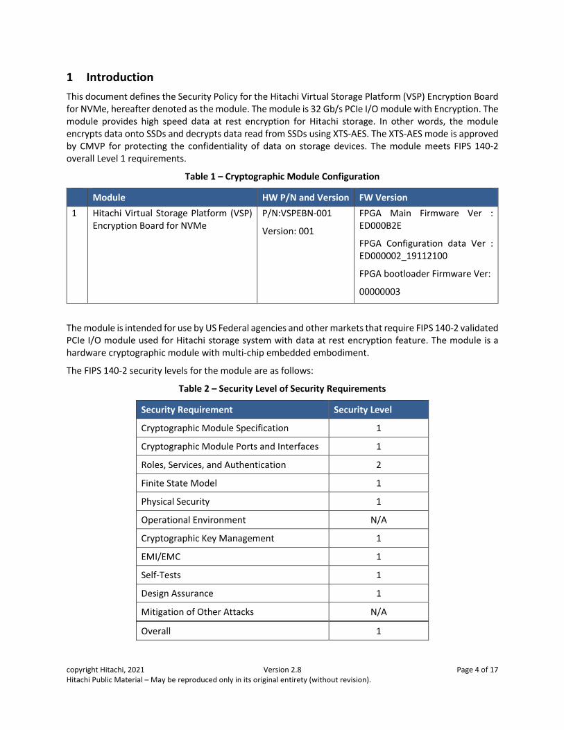
1 Introduction
This document defines the Security Policy for the Hitachi Virtual Storage Platform (VSP) Encryption Board for NVMe, hereafter denoted as the module. The module is 32 Gb/s PCIe I/O module with Encryption. The module provides high speed data at rest encryption for Hitachi storage. In other words, the module encrypts data onto SSDs and decrypts data read from SSDs using XTS-AES. The XTS-AES mode is approved by CMVP for protecting the confidentiality of data on storage devices. The module meets FIPS 140-2 overall Level 1 requirements.
Table 1 – Cryptographic Module Configuration
Module HW P/N and Version FW Version
1 Hitachi Virtual Storage Platform (VSP) Encryption Board for NVMe
P/N:VSPEBN-001
Version: 001
FPGA Main Firmware Ver : ED000B2E
FPGA Configuration data Ver : ED000002_19112100
FPGA bootloader Firmware Ver:
00000003
The module is intended for use by US Federal agencies and other markets that require FIPS 140-2 validated PCIe I/O module used for Hitachi storage system with data at rest encryption feature. The module is a hardware cryptographic module with multi-chip embedded embodiment.
The FIPS 140-2 security levels for the module are as follows:
Table 2 – Security Level of Security Requirements
Security Requirement Security Level
Cryptographic Module Specification 1
Cryptographic Module Ports and Interfaces 1
Roles, Services, and Authentication 2
Finite State Model 1
Physical Security 1
Operational Environment N/A
Cryptographic Key Management 1
EMI/EMC 1
Self-Tests 1
Design Assurance 1
Mitigation of Other Attacks N/A
Overall 1
copyright Hitachi, 2021 Version 2.8 Page 5 of 17 Hitachi Public Material – May be reproduced only in its original entirety (without revision).
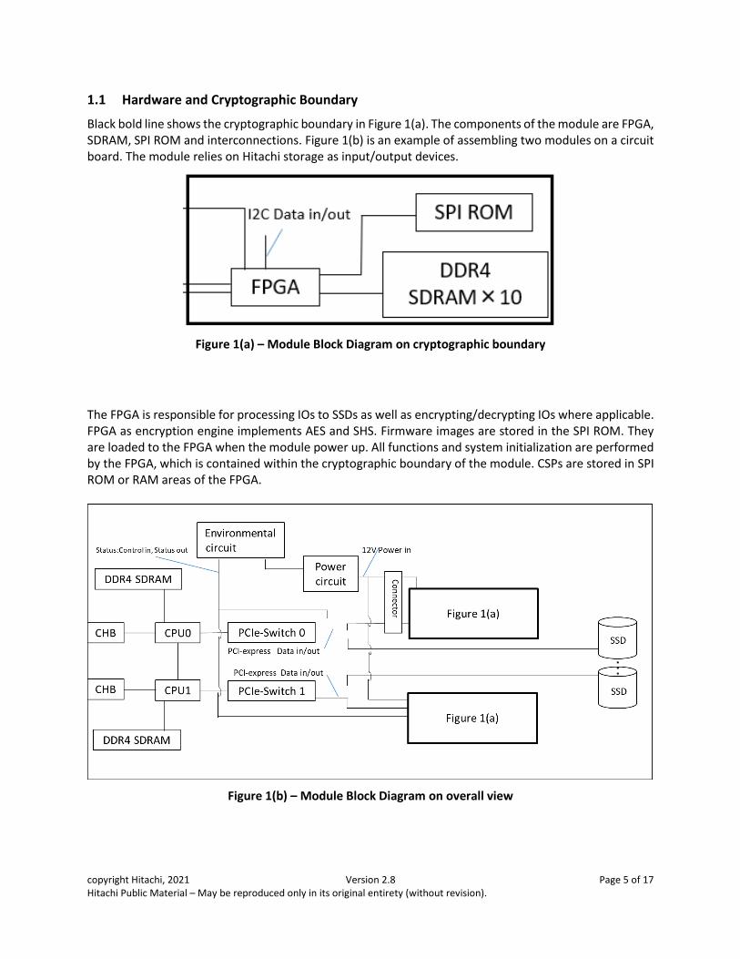
1.1 Hardware and Cryptographic Boundary
Black bold line shows the cryptographic boundary in Figure 1(a). The components of the module are FPGA, SDRAM, SPI ROM and interconnections. Figure 1(b) is an example of assembling two modules on a circuit board. The module relies on Hitachi storage as input/output devices.
Figure 1(a) – Module Block Diagram on cryptographic boundary
The FPGA is responsible for processing IOs to SSDs as well as encrypting/decrypting IOs where applicable. FPGA as encryption engine implements AES and SHS. Firmware images are stored in the SPI ROM. They are loaded to the FPGA when the module power up. All functions and system initialization are performed by the FPGA, which is contained within the cryptographic boundary of the module. CSPs are stored in SPI ROM or RAM areas of the FPGA.
Figure 1(b) – Module Block Diagram on overall view
copyright Hitachi, 2021 Version 2.8 Page 6 of 17 Hitachi Public Material – May be reproduced only in its original entirety (without revision).
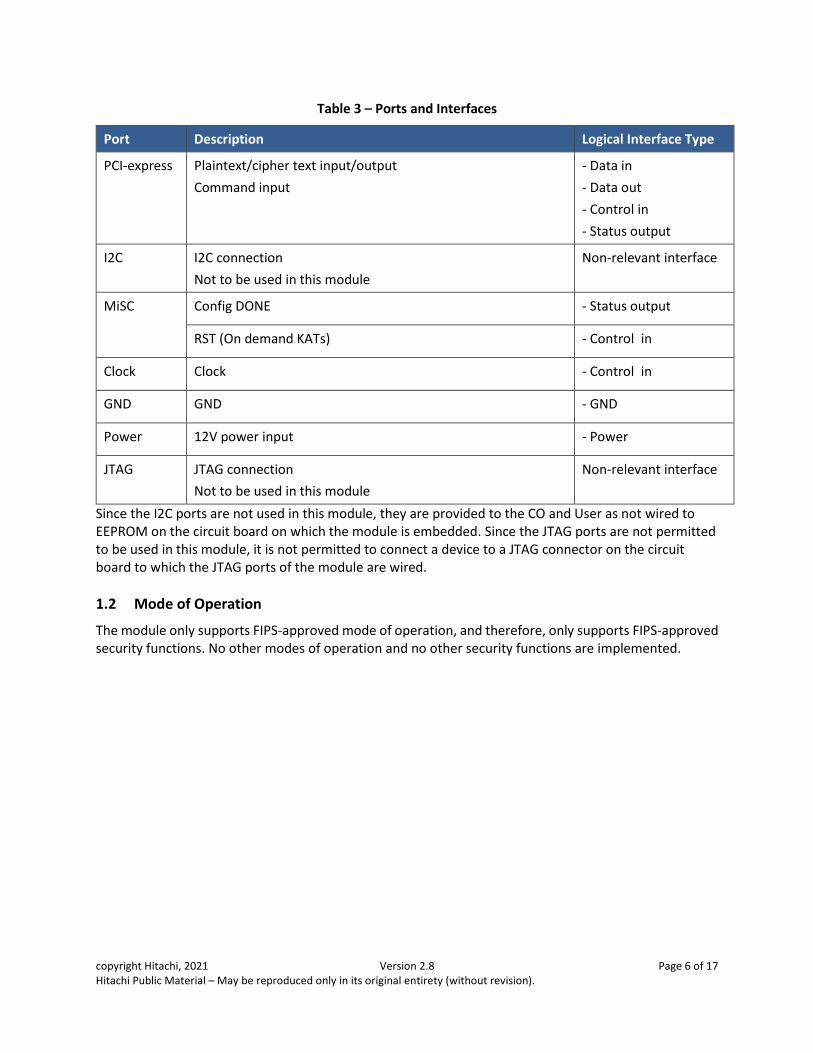
Table 3 – Ports and Interfaces
Port Description Logical Interface Type
PCI-express Plaintext/cipher text input/output
Command input
- Data in
- Data out
- Control in
- Status output
I2C I2C connection
Not to be used in this module
Non-relevant interface
MiSC Config DONE - Status output
RST (On demand KATs) - Control in
Clock Clock - Control in
GND GND - GND
Power 12V power input - Power
JTAG JTAG connection
Not to be used in this module
Non-relevant interface
Since the I2C ports are not used in this module, they are provided to the CO and User as not wired to EEPROM on the circuit board on which the module is embedded. Since the JTAG ports are not permitted to be used in this module, it is not permitted to connect a device to a JTAG connector on the circuit board to which the JTAG ports of the module are wired.
1.2 Mode of Operation
The module only supports FIPS-approved mode of operation, and therefore, only supports FIPS-approved security functions. No other modes of operation and no other security functions are implemented.
copyright Hitachi, 2021 Version 2.8 Page 7 of 17 Hitachi Public Material – May be reproduced only in its original entirety (without revision).
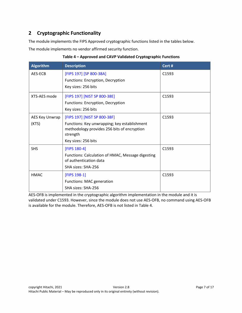
2 Cryptographic Functionality
The module implements the FIPS Approved cryptographic functions listed in the tables below.
The module implements no vendor affirmed security function.
Table 4 – Approved and CAVP Validated Cryptographic Functions
Algorithm Description Cert #
AES-ECB [FIPS 197] [SP 800-38A]
Functions: Encryption, Decryption
Key sizes: 256 bits
C1593
XTS-AES mode [FIPS 197] [NIST SP 800-38E]
Functions: Encryption, Decryption
Key sizes: 256 bits
C1593
AES Key Unwrap
(KTS)
[FIPS 197] [NIST SP 800-38F]
Functions: Key unwrapping; key establishment methodology provides 256 bits of encryption strength
Key sizes: 256 bits
C1593
SHS [FIPS 180-4]
Functions: Calculation of HMAC, Message digesting of authentication data
SHA sizes: SHA-256
C1593
HMAC [FIPS 198-1]
Functions: MAC generation
SHA sizes: SHA-256
C1593
AES-OFB is implemented in the cryptographic algorithm implementation in the module and it is validated under C1593. However, since the module does not use AES-OFB, no command using AES-OFB is available for the module. Therefore, AES-OFB is not listed in Table 4.
copyright Hitachi, 2021 Version 2.8 Page 8 of 17 Hitachi Public Material – May be reproduced only in its original entirety (without revision).
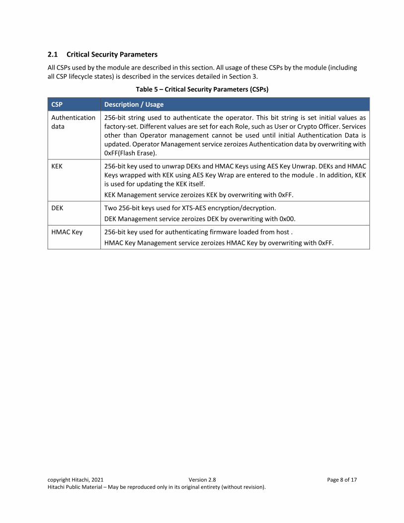
2.1 Critical Security Parameters
All CSPs used by the module are described in this section. All usage of these CSPs by the module (including all CSP lifecycle states) is described in the services detailed in Section 3.
Table 5 – Critical Security Parameters (CSPs)
CSP Description / Usage
Authentication data
256-bit string used to authenticate the operator. This bit string is set initial values as factory-set. Different values are set for each Role, such as User or Crypto Officer. Services other than Operator management cannot be used until initial Authentication Data is updated. Operator Management service zeroizes Authentication data by overwriting with 0xFF(Flash Erase).
KEK
256-bit key used to unwrap DEKs and HMAC Keys using AES Key Unwrap. DEKs and HMAC Keys wrapped with KEK using AES Key Wrap are entered to the module . In addition, KEK is used for updating the KEK itself.
KEK Management service zeroizes KEK by overwriting with 0xFF.
DEK Two 256-bit keys used for XTS-AES encryption/decryption.
DEK Management service zeroizes DEK by overwriting with 0x00.
HMAC Key
256-bit key used for authenticating firmware loaded from host .
HMAC Key Management service zeroizes HMAC Key by overwriting with 0xFF.

copyright Hitachi, 2021 Version 2.8 Page 9 of 17 Hitachi Public Material – May be reproduced only in its original entirety (without revision).
3 Roles, Authentication and Services
3.1 Assumption of Roles
The module supports two distinct operator roles, User and Cryptographic Officer (CO). The cryptographic module enforces the separation of roles, since concurrent operators are not supported. Re-authentication is enforced when changing roles. An operator is required to log out before another operator can log in, or change a role to another role using an authentication data of another role.
Table 6 lists all operator roles supported by the module. The module does not support a maintenance role and bypass capability. After the module powers off, all the data stored in SDRAM, including previously authenticated operators, are cleared. All CSPs are protected through APIs and logic developed for the sole purpose of integration into specific Hitachi host platforms. Only Hitachi-authored drivers can access cryptographic APIs. Further, the module functionally does not allow keys and authentication data to be disclosed, modified, or substituted in FIPS mode of operation.
Table 6 – Roles Description
Role ID Role Description Authentication Type Authentication Data
CO Cryptographic Officer – The role which used to FPGA assumed to perform cryptographic initialization or management functions.
Role-based 256-bit string
User User – The role assumed to perform general security services, including cryptographic operations and other approved security functions.
Role-based 256-bit string
copyright Hitachi, 2021 Version 2.8 Page 10 of 17 Hitachi Public Material – May be reproduced only in its original entirety (without revision).
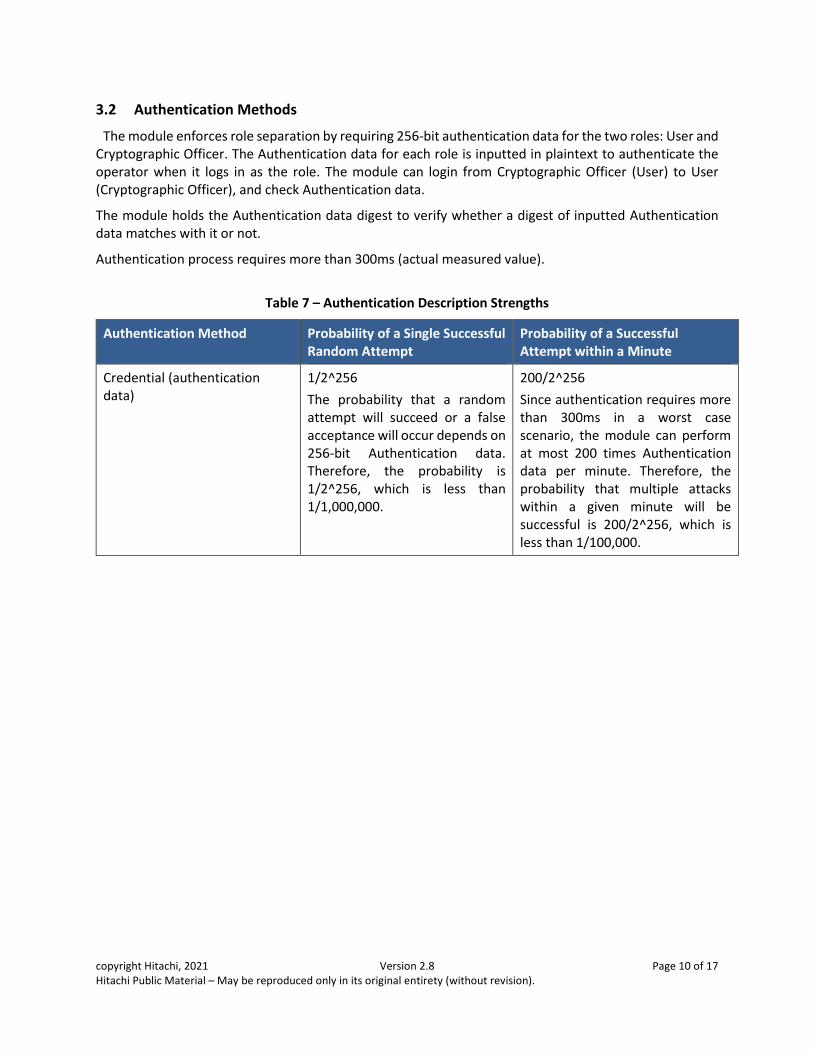
3.2 Authentication Methods
The module enforces role separation by requiring 256-bit authentication data for the two roles: User and Cryptographic Officer. The Authentication data for each role is inputted in plaintext to authenticate the operator when it logs in as the role. The module can login from Cryptographic Officer (User) to User (Cryptographic Officer), and check Authentication data.
The module holds the Authentication data digest to verify whether a digest of inputted Authentication data matches with it or not.
Authentication process requires more than 300ms (actual measured value).
Table 7 – Authentication Description Strengths
Authentication Method Probability of a Single Successful Random Attempt
Probability of a Successful Attempt within a Minute
Credential (authentication data)
1/2^256
The probability that a random attempt will succeed or a false acceptance will occur depends on 256-bit Authentication data. Therefore, the probability is 1/2^256, which is less than 1/1,000,000.
200/2^256
Since authentication requires more than 300ms in a worst case scenario, the module can perform at most 200 times Authentication data per minute. Therefore, the probability that multiple attacks within a given minute will be successful is 200/2^256, which is less than 1/100,000.

copyright Hitachi, 2021 Version 2.8 Page 11 of 17 Hitachi Public Material – May be reproduced only in its original entirety (without revision).
3.3 Services
All services implemented by the module are listed in the tables below. Each service description also describes all usage of CSPs by the service. Also, Table 8 shows the role that is able to perform the service.
Table 8 – Authenticated Services
Service Description CO User
Operator Management Adds an operator’s role, and an Authentication data, updates the Authentication data and zeroizes one or all operators and Authentication data
X X
Logout Operator logout of the module
This service can execute when operator logged in
X X
Decrypt Decrypts data using XTS-AES X
Encrypt Encrypts data using XTS-AES X
DEK Management Loads, updates and zeroizes DEKs X X
KEK Management Loads, updates and zeroizes KEKs X X
HMAC Key Management Loads, updates and zeroizes the HMAC key X X
Firmware Update Updates the FPGA Main Firmware X X
Abort Abort Decrypt and Encrypt X
Table 9 shows the services that are available without an operator authentication.
Table 9 – Unauthenticated Services
Service Description
On demand power up self-tests
Perform power off/on
On demand KATs Perform KATs
Login Authenticates operators
Get Current Operator Get the operator’s role and an identity string of the current operator
Revert Zeroizes CSPs, and an Authentication data returns initialization.
Show Status Show module status with LEDs or bits in a status register
Refer to backend NVMe IF specification about bits in a status register as MRPC command
Hardware Setting Initialize hardware settings
copyright Hitachi, 2021 Version 2.8 Page 12 of 17 Hitachi Public Material – May be reproduced only in its original entirety (without revision).
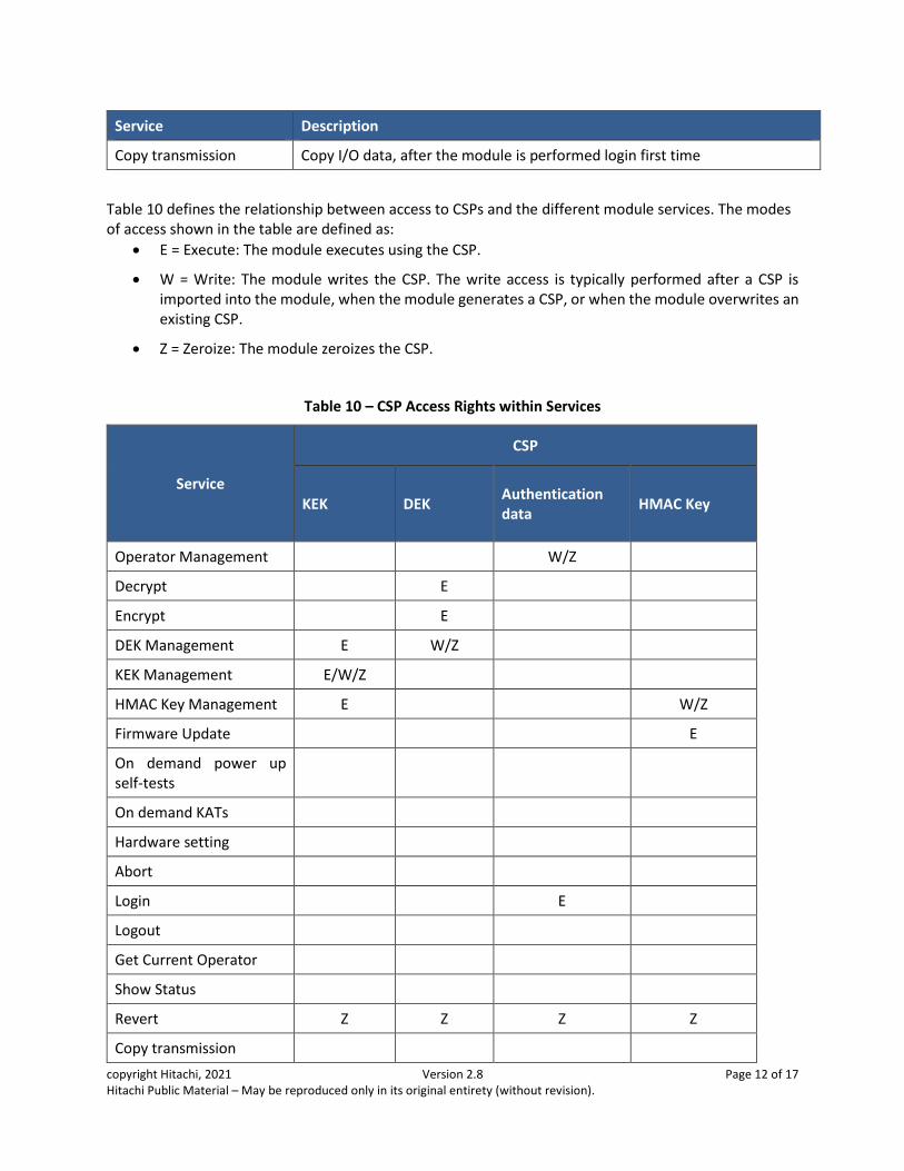
Service Description
Copy transmission Copy I/O data, after the module is performed login first time
Table 10 defines the relationship between access to CSPs and the different module services. The modes of access shown in the table are defined as:
• E = Execute: The module executes using the CSP.
• W = Write: The module writes the CSP. The write access is typically performed after a CSP is imported into the module, when the module generates a CSP, or when the module overwrites an existing CSP.
• Z = Zeroize: The module zeroizes the CSP.
Table 10 – CSP Access Rights within Services
Service
CSP
KEK DEK Authentication data
HMAC Key
Operator Management W/Z
Decrypt E
Encrypt E
DEK Management E W/Z
KEK Management E/W/Z
HMAC Key Management E W/Z
Firmware Update E
On demand power up self-tests
On demand KATs
Hardware setting
Abort
Login E
Logout
Get Current Operator
Show Status
Revert Z Z Z Z
Copy transmission

copyright Hitachi, 2021 Version 2.8 Page 13 of 17 Hitachi Public Material – May be reproduced only in its original entirety (without revision).
4 Self-tests
Each time the module is powered up it tests that the cryptographic algorithms still operate correctly and that sensitive data have not been damaged. Power up self-tests are available on demand by power cycling.
On power up or reset, the module performs the self-tests described in Table 11 below. Each Firmware Integrity test and all Cryptographic Algorithm Known Answer tests (hereafter KATs) must be completed successfully prior to any other use of cryptography by the module. If Firmware Integrity test or one of the KATs fails, the module enters the error state. If one of the KATs fails, the module shows the result of self-tests with bits in an register status are set as “1b”. If Firmware Integrity test fail, signal path(connected PCIe-Switch to the module) doesn’t link up. As a result, the register status is not observable when the Firmware Integrity test is failed, because of the link down of the signal path. Therefore, the link down of the signal path is an indicator for the Firmware Integrity test failure.
Self-tests do not require any intervention or input from the operator. Power up self-tests are automatically executed when the module is powered up. Conditional self-tests are automatically performed when an applicable security function or operation is invoked.
Table 11 – Power Up Self-tests
Test Target Description
Firmware Integrity 16 or 32 bit CRC performed over all code in Flash memory.
XTS-AES mode KATs: Encryption, Decryption Key size: 256 bits
AES Key Unwrap KAT: Unwrap Key size: 256 bits
HMAC KAT: Verification SHA size: SHA-256
Note1: The SHA-256 algorithm doesn’t perform independently for self-test, but is performed the self-tests using HMAC ; thus, the SHA-256 doesn’t describe Table 11.
Note2: The AES ECB (256bit) algorithm doesn’t perform independently for self-test, but is performed the self-tests using XTS-AES ; thus, the AES ECB doesn’t describe Table 11.
Note3: Perform 16bit CRC for FPGA Main Firmware
Perform 32bit CRC for FPGA bootloader Firmware and Configuration data
As the FPGA Main Firmware is being externally sent to the module, the firmware images are authenticated using the HMAC authentication technique. Both a loaded firmware image and the HMAC key stored in the module are fed into the SHA engine, together with the proper SHA-256 algorithm, the calculated HMAC digest is compared with the one embedded in the firmware image. If they don't equal, the firmware authentication fails and the module indicate the state. If “Firmware Update” results in failure, the admin status field code of 11XXb is sent from the FPGA as the response.
On demand, the module performs KATs as other conditional self-test. At this time, If one of the KATs fails, the module enters the KATs error state. If one of the KATs fails, the module shows the result of self-tests with bits in an register status are set as “1b”.
copyright Hitachi, 2021 Version 2.8 Page 14 of 17 Hitachi Public Material – May be reproduced only in its original entirety (without revision).
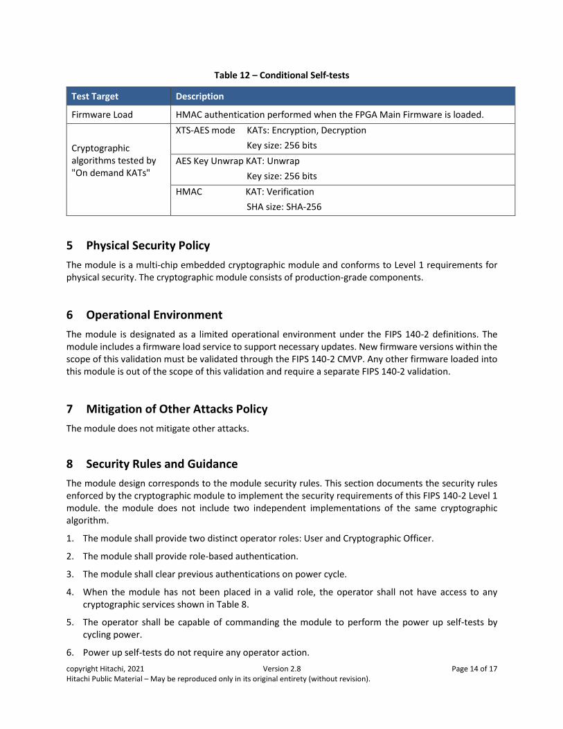
Table 12 – Conditional Self-tests
Test Target Description
Firmware Load HMAC authentication performed when the FPGA Main Firmware is loaded.
Cryptographic algorithms tested by "On demand KATs"
XTS-AES mode KATs: Encryption, Decryption
Key size: 256 bits
AES Key Unwrap KAT: Unwrap
Key size: 256 bits
HMAC KAT: Verification
SHA size: SHA-256
5 Physical Security Policy
The module is a multi-chip embedded cryptographic module and conforms to Level 1 requirements for physical security. The cryptographic module consists of production-grade components.
6 Operational Environment
The module is designated as a limited operational environment under the FIPS 140-2 definitions. The module includes a firmware load service to support necessary updates. New firmware versions within the scope of this validation must be validated through the FIPS 140-2 CMVP. Any other firmware loaded into this module is out of the scope of this validation and require a separate FIPS 140-2 validation.
7 Mitigation of Other Attacks Policy
The module does not mitigate other attacks.
8 Security Rules and Guidance
The module design corresponds to the module security rules. This section documents the security rules enforced by the cryptographic module to implement the security requirements of this FIPS 140-2 Level 1 module. the module does not include two independent implementations of the same cryptographic algorithm.
1. The module shall provide two distinct operator roles: User and Cryptographic Officer.
2. The module shall provide role-based authentication.
3. The module shall clear previous authentications on power cycle.
4. When the module has not been placed in a valid role, the operator shall not have access to any cryptographic services shown in Table 8.
5. The operator shall be capable of commanding the module to perform the power up self-tests by cycling power.
6. Power up self-tests do not require any operator action.
copyright Hitachi, 2021 Version 2.8 Page 15 of 17 Hitachi Public Material – May be reproduced only in its original entirety (without revision).
7. Data output shall be inhibited during power up self-tests, zeroization, and error states.
8. Status information does not contain CSPs or sensitive data that if misused could lead to a compromise of the module.
9. There are no restrictions on which keys or CSPs are zeroized by the zeroization service.
10. The module does not support concurrent operators .
11. The module does not support a maintenance interface or role.
12. The module does not support manual key entry.
13. The module does not have any external input/output devices used for entry/output of data.
14. The module does not output plaintext CSPs.
8.1 Crypto Officer Guidance
The approved security functions for the CO role is included in Table 8 of the security policy (the services allocated for the "CO" role).
There is no physical port and logical interface dedicated to the CO only.
Since this module (a set of the FPGA, the SPI ROM and the SDRAM) is assumed to be delivered to the Crypto Officer as embedded on a circuit board, the installation procedure is not included in this guidance. Since the JTAG ports are not permitted to be used in this module, it is not permitted to connect a device to a JTAG connector on the circuit board to which the JTAG ports of the module are wired.
The following personalization procedure by which the operator is authenticated upon accessing the module for the first time.
1. Supply power into the module through the circuit board in which the module is embedded.
2. Update or set the authentication data, KEK, DEK and HMAC Key by the following personalization procedures when the module is accessed for the first time.
a. Log in as the CO role with the factory setting CO authentication data. Use the Login service. b. Replace a default KEK with a unique KEK. Use the KEK Management service.
c. Change the CO and User authentication data. Use the Operator Management service.
d. Transfer DEK to FPGA. Use the DEK Management service.
e. Transfer HMAC Key to FPGA. Use the HMAC Key Management service.
f. Close the Login session. Use the Logout service.
8.2 User Guidance
The approved security functions for the user role is included in Table 8 of the security policy (the services allocated for the "User" role). Refer to Hard Micro IF Specification for the details of the security functions.
There is no physical port and logical interface dedicated to the User only.
copyright Hitachi, 2021 Version 2.8 Page 16 of 17 Hitachi Public Material – May be reproduced only in its original entirety (without revision).
The user responsibilities necessary for the secure operation of the module is below.
Since the JTAG ports are not permitted to be used in this module, it is not permitted to connect a device to a JTAG connector on the circuit board to which the JTAG ports of the module are wired.
8.3 Firmware Update
In order to update the FPGA Main Firmware, the Firmware Update service is used. This service is permitted to both CO and User roles. When the Firmware Update command is called, the firmware code for update is loaded and stored to the standby area of the firmware that is on the SPI ROM. After finishing to store the loaded firmware code to the standby area, the loaded firmware is authenticated by the Firmware Load test. If the module passes the test, the standby area in which the loaded firmware is stored is changed to the active area, and the loaded firmware is used in the module after reset. If the module fails the test, the standby area is not changed to the active area, and therefore, the loaded firmware in the standby area is not used.
9 Design Assurance Policy
9.1 Configuration Management Overview
Programs and documents are managed using proprietary web-based configuration management system (Electric Stock System). Documents for validation and hardware components are managed by revision management by proprietary ledger.
9.2 Installation, Initialization, and Start-up Overview
The procedure is described in section 8.1.
copyright Hitachi, 2021 Version 2.8 Page 17 of 17 Hitachi Public Material – May be reproduced only in its original entirety (without revision).
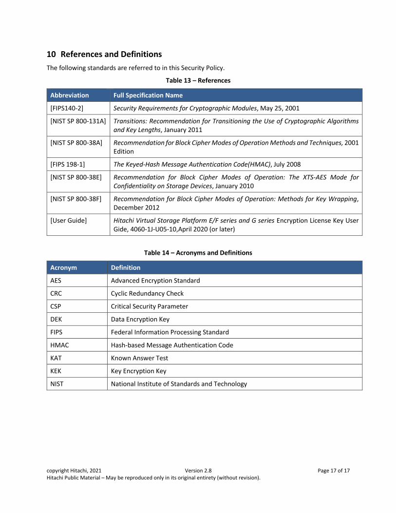
10 References and Definitions
The following standards are referred to in this Security Policy.
Table 13 – References
Abbreviation Full Specification Name
[FIPS140-2] Security Requirements for Cryptographic Modules, May 25, 2001
[NIST SP 800-131A] Transitions: Recommendation for Transitioning the Use of Cryptographic Algorithms and Key Lengths, January 2011
[NIST SP 800-38A] Recommendation for Block Cipher Modes of Operation Methods and Techniques, 2001 Edition
[FIPS 198-1] The Keyed-Hash Message Authentication Code(HMAC), July 2008
[NIST SP 800-38E] Recommendation for Block Cipher Modes of Operation: The XTS-AES Mode for Confidentiality on Storage Devices, January 2010
[NIST SP 800-38F] Recommendation for Block Cipher Modes of Operation: Methods for Key Wrapping, December 2012
[User Guide] Hitachi Virtual Storage Platform E/F series and G series Encryption License Key User Gide, 4060-1J-U05-10,April 2020 (or later)
Table 14 – Acronyms and Definitions
Acronym Definition
AES Advanced Encryption Standard
CRC Cyclic Redundancy Check
CSP Critical Security Parameter
DEK Data Encryption Key
FIPS Federal Information Processing Standard
HMAC Hash-based Message Authentication Code
KAT Known Answer Test
KEK Key Encryption Key
NIST National Institute of Standards and Technology