Embed Size (px)
Citation preview

Hitachi Command SuiteAdministrator Guide
MK-90HC175-16
Document Organization
Product Version
Getting Help
Contents

© 2014 Hitachi, Ltd. All rights reserved.
No part of this publication may be reproduced or transmitted in any form or by any means,electronic or mechanical, including photocopying and recording, or stored in a database or retrievalsystem for any purpose without the express written permission of Hitachi, Ltd.
Hitachi, Ltd., reserves the right to make changes to this document at any time without notice andassumes no responsibility for its use. This document contains the most current information availableat the time of publication. When new or revised information becomes available, this entiredocument will be updated and distributed to all registered users.
Some of the features described in this document might not be currently available. Refer to the mostrecent product announcement for information about feature and product availability, or contactHitachi Data Systems Corporation at https://portal.hds.com.
Notice: Hitachi, Ltd., products and services can be ordered only under the terms and conditions ofthe applicable Hitachi Data Systems Corporation agreements. The use of Hitachi, Ltd., products isgoverned by the terms of your agreements with Hitachi Data Systems Corporation.
Hitachi is a registered trademark of Hitachi, Ltd., in the United States and other countries. HitachiData Systems is a registered trademark and service mark of Hitachi, Ltd., in the United States andother countries.
Archivas, Essential NAS Platform, HiCommand, Hi-Track, ShadowImage, Tagmaserve, Tagmasoft,Tagmasolve, Tagmastore, TrueCopy, Universal Star Network, and Universal Storage Platform areregistered trademarks of Hitachi Data Systems.
AIX, AS/400, DB2, Domino, DS6000, DS8000, Enterprise Storage Server, ESCON, FICON,FlashCopy, IBM, Lotus, MVS, OS/390, RS/6000, S/390, System z9, System z10, Tivoli, VM/ESA,z/OS, z9, z10, zSeries, z/VM, and z/VSE are registered trademarks or trademarks of InternationalBusiness Machines Corporation.
All other trademarks, service marks, and company names in this document or web site areproperties of their respective owners.
Microsoft product screen shots are reprinted with permission from Microsoft Corporation.
Notice on Export Controls. The technical data and technology inherent in this Document may besubject to U.S. export control laws, including the U.S. Export Administration Act and its associatedregulations, and may be subject to export or import regulations in other countries. Reader agrees tocomply strictly with all such regulations and acknowledges that Reader has the responsibility toobtain licenses to export, re-export, or import the Document and any Compliant Products.
iiHitachi Command Suite Administrator Guide

Contents
Preface................................................................................................ xxiIntended audience.................................................................................................. xxiiProduct version.......................................................................................................xxiiRelease notes.........................................................................................................xxiiDocument revision level.......................................................................................... xxiiDocument organization...........................................................................................xxiiiRelated documents................................................................................................ xxivDocument conventions............................................................................................xxvConventions for storage capacity values................................................................... xxvAccessing product documentation........................................................................... xxviGetting help...........................................................................................................xxviComments............................................................................................................ xxvii
1 System configuration and requirements..................................................1-1System configuration.............................................................................................. 1-3Network security configuration.................................................................................1-6
Common security risks...................................................................................... 1-6Security configuration recommended for Device Manager.................................... 1-7
System requirements for the management server and Host Data Collector computers. 1-8Maximum number of resources that can be managed..........................................1-8Changing the memory heap size........................................................................1-9Changing the JDK of management servers........................................................1-10Changing the Java execution environment used by Host Data Collector.............. 1-11
Hosts that can be managed by Device Manager...................................................... 1-12Host management software supported by Device Manager.......................................1-13Prerequisites for normal hosts................................................................................1-14
Prerequisites for normal hosts managed by Host Data Collector ........................ 1-14Prerequisites for normal hosts managed by Device Manager agent.....................1-16
Prerequisites for virtual machines...........................................................................1-17Prerequisites for virtual machines managed by Host Data Collector.................... 1-17Prerequisites for virtual machines managed by Device Manager agent................ 1-20Operation workflow for allocating volumes to virtual machines...........................1-22Tasks required to change the virtual machine configuration............................... 1-25
Prerequisites for virtualization servers.....................................................................1-26Prerequisites for virtualization servers.............................................................. 1-26Operation workflow for managing virtualization servers..................................... 1-27
iiiHitachi Command Suite Administrator Guide

Notes on operating virtualization servers.......................................................... 1-28Prerequisites for mainframe hosts.......................................................................... 1-28
Operation workflow of managing a mainframe host...........................................1-29Prerequisites for file servers...................................................................................1-29
Environment settings for Hitachi NAS Platform family........................................ 1-29Environment settings for Hitachi Data Ingestor and Hitachi NAS Platform F.........1-31Operation workflow of managing file servers.....................................................1-32Notes on operating file servers........................................................................ 1-33
Related products...................................................................................................1-33System requirements for managing copy pairs........................................................ 1-34System configuration for managing copy pairs........................................................ 1-35
System configuration for using the local management method to manage copy pairs..................................................................................................................... 1-36System configuration for using the central management method to manage copypairs.............................................................................................................. 1-40System configuration for using a virtual command device server configuration tomanage copy pairs..........................................................................................1-44System configuration for using an SVP configuration to manage copy pairs (whencopy pairs are defined in a configuration definition file)..................................... 1-48System configuration for using an SVP configuration to manage copy pairs (whencopy pairs are defined as a device group).........................................................1-50
Storage system requirements for managing copy pairs............................................ 1-53Prerequisite version of the Device Manager agent for managing copy pairs .............. 1-58Notes on managing copy pairs............................................................................... 1-60Configuring a high availability system..................................................................... 1-65
Example of a configuration for configuring a high availability system.................. 1-65Requirements for configuring a high availability system..................................... 1-67
Notes on executing commands...............................................................................1-69
2 Network configuration...........................................................................2-1Ports used by Hitachi Command Suite products.........................................................2-2
Ports used by Common Component................................................................... 2-2Ports used by the Device Manager server........................................................... 2-3Ports used by the Tiered Storage Manager server............................................... 2-5Ports used by Host Data Collector......................................................................2-5Ports used by the Device Manager agent............................................................2-7Ports used by storage systems.......................................................................... 2-7
Changing ports used by Common Component......................................................... 2-10Registering firewall exceptions for Device Manager and Tiered Storage Manager....... 2-15
Port numbers that must be registered as firewall exceptions for Device Manager andTiered Storage Manager.................................................................................. 2-15Registering firewall exceptions for Device Manager and Tiered Storage Manager inWindows........................................................................................................2-28Registering firewall exceptions for Device Manager and Tiered Storage Manager inRed Hat Enterprise Linux.................................................................................2-29Registering firewall exceptions for Device Manager and Tiered Storage Manager inSUSE Linux Enterprise Server...........................................................................2-29
Registering firewall exceptions for Host Data Collector (Windows) ........................... 2-30Registering an exception for the Host Data Collector service (for non-SSLcommunication)..............................................................................................2-30Registering an exception for the Host Data Collector service (for SSL communication)..................................................................................................................... 2-31
ivHitachi Command Suite Administrator Guide

Network settings with multiple IP addresses........................................................... 2-32Network settings for using a management server as a bridge ............................2-32Specifying settings if the Host Data Collector machine has multiple IP addresses.2-33
Device Manager settings in IPv6 environments........................................................2-33Settings for migrating Device Manager to an IPv6 environment..........................2-34Settings for linking with storage systems that support IPv6................................2-35
Changing the IP address or host name of the management server........................... 2-36Changing the host name of the management server..........................................2-36Changing the IP address of the management server..........................................2-38Required operations after changing the IP address or host name of the managementserver............................................................................................................ 2-39
Changing the URL for accessing Hitachi Command Suite products (hcmds64chgurlcommand)............................................................................................................2-41
3 User account management....................................................................3-1About password policies.......................................................................................... 3-2
Setting password policies.................................................................................. 3-2About account locking............................................................................................. 3-3
About account locking policies........................................................................... 3-4Setting account locking policies......................................................................... 3-4Settings for automatically locking the System account......................................... 3-5Unlocking accounts...........................................................................................3-6
User management on an external authentication server.............................................3-7About linking to an external authentication server ..............................................3-7About linking to an external authorization server.................................................3-7Operating workflow for user authentication on an external authentication server.. 3-8
Operating workflow for user authentication on an LDAP directory server..... 3-8Operating workflow for user authentication on a RADIUS server............... 3-10Operation workflow for user authentication on a Kerberos server .............3-12
Account conditions for Hitachi Command Suite products.................................... 3-14About the data structures of user entries..........................................................3-15
About the hierarchical structure model....................................................3-15About the flat model..............................................................................3-16About the BaseDN................................................................................. 3-17
Registering an external authentication server and an external authorization server3-17Setup items in the exauth.properties file for LDAP authentication..............3-19Examples of setting the exauth.properties file for LDAP authentication...... 3-25Setup items in the exauth.properties file for RADIUS authentication..........3-26Examples of setting the exauth.properties file for RADIUS authentication.. 3-33Setup items in the exauth.properties file for Kerberos authentication.........3-34Examples of setting the exauth.properties file for Kerberos authentication.3-40
About a LDAP search user account...................................................................3-41Conditions for LDAP search user account.................................................3-42Registering an LDAP search user account................................................3-43Deleting an LDAP search user account.................................................... 3-45Checking the LDAP directory server that registered LDAP search user account............................................................................................................3-45
Registering a shared secret............................................................................. 3-46Deleting a shared secret........................................................................ 3-46Checking the RADIUS server that registered a shared secret on themanagement server...............................................................................3-47
vHitachi Command Suite Administrator Guide

Checking connections to an external authentication server and an externalauthorization server........................................................................................ 3-47Notes on commands for setting up a link to an external authentication server.....3-49Encryption types for Kerberos authentication.................................................... 3-50
4 Security............................................................................................... 4-1Login warning banners............................................................................................4-2
Conditions that apply when displaying warning banner messages.........................4-2Creating and registering a message displayed on a warning banner..................... 4-2Deleting a message from the warning banner.....................................................4-4
Communication security mode................................................................................. 4-5Secure communication for Device Manager and Tiered Storage Manager.............. 4-5
Operation workflow for secure communication between a management serverand a management client (GUI)............................................................... 4-9Operation workflow for secure communication between a management serverand a management client (Device Manager CLI)......................................4-11Operation workflow for secure communication between a management serverand a management client (Tiered Storage Manager CLI).......................... 4-12Operation workflow for secure communication between an LDAP directoryserver and a management server .......................................................... 4-13Operation workflow for secure communication between a Device Managerserver and Replication Manager server....................................................4-14Operation workflow for secure communication between a Tuning Managerserver and a Device Manager server....................................................... 4-16Operation workflow for secure communication between a Host Data Collectormachine and a management server........................................................ 4-17Operation workflow for secure communication between a virtualization serverand Host Data Collector......................................................................... 4-19Operation workflow for secure communication between a management serverand Device Manager agent.....................................................................4-20Operation workflow for secure communication between a storage system anda management server ...........................................................................4-22Operation workflow for secure communication between a management serverand a storage system (VSP G1000).........................................................4-22Operation workflow for secure communication between an SMI-S provider anda management server............................................................................4-23Operation workflow for secure communication between a Tuning ManagerAgent and a Tuning Manager server....................................................... 4-24Operation workflow for secure communication between a Tuning Managerserver and a Tuning Manager API client.................................................. 4-25Operation workflow for secure communication between a storage system anda management client (GUI)....................................................................4-25Operation workflow for secure communication between a management serverand a CIM client (object operations)....................................................... 4-26Operation workflow for secure communication between a management serverand a CIM client (two-way authentication for object operations)............... 4-27Operation workflow for secure communication between a management serverand a CIM client (event indications)........................................................4-29Operation workflow for secure communication between a management serverand a CIM client (two-way authentication for event indications)................4-29Truststores........................................................................................... 4-30
Configuring an SSL server (Common Component)............................................. 4-33
viHitachi Command Suite Administrator Guide

Creating a secret key and a certificate signing request for CommonComponent .......................................................................................... 4-33Applying to a certificate authority for a Common Component server certificate............................................................................................................4-36Editing the user_httpsd.conf file............................................................. 4-36Closing the port for the non-SSL communication (HBase 64 Storage MgmtWeb Service)........................................................................................ 4-39
Configuring an SSL server (Device Manager server)...........................................4-41Creating a key pair and a self-signed certificate for Device Manager server4-41Enabling SSL/TLS for the Device Manager server..................................... 4-44Creating a certificate signing request for Device Manager server...............4-45Applying to a certificate authority for a Device Manager server certificate..4-46Importing a server certificate into the Device Manager server keystore..... 4-47Viewing the Device Manager server key pair information in normal mode.. 4-48Viewing the Device Manager server key pair information in verbose mode.4-49Deleting a key pair from the Device Manager server keystore................... 4-50Changing the password of a Device Manager server key pair.................... 4-50Changing the password of the Device Manager server keystore................ 4-51Importing a certificate into the Device Manager server truststore..............4-52Viewing the Device Manager server truststore information in normal mode4-53Viewing the Device Manager server truststore information in verbose mode............................................................................................................4-53Deleting a server certificate from the Device Manager server truststore.....4-54Changing the password of the Device Manager server truststore...............4-56
Configuring an SSL server (Host Data Collector)................................................4-56Creating a key pair and a certificate signing request for Host Data Collector............................................................................................................4-56Applying to a certificate authority for a Host Data Collector server certificate............................................................................................................4-58Importing the Host Data Collector server certificates into the keystore...... 4-59
Configuring an SSL server (Tuning Manager Agent host)................................... 4-60Creating a secret key and a certificate signing request for Tuning ManagerAgent host............................................................................................4-60Applying to a certificate authority for an Tuning Manager Agent host servercertificate..............................................................................................4-62Enabling SSL/TLS (Tuning Manager Agent host)...................................... 4-62
Configuring an SSL client.................................................................................4-65Downloading a Device Manager server truststore file............................... 4-65Exporting a Device Manager server self-signed certificate.........................4-66Importing a server certificate into a Web browser....................................4-66Changing pop-up blocker settings...........................................................4-67Enabling SSL/TLS for the Device Manager CLI computer.......................... 4-68Downloading the Tiered Storage Manager server truststore files............... 4-69Enabling SSL/TLS for the Tiered Storage Manager CLI computer...............4-70Importing a certificate into the truststore for Hitachi Command Suite........ 4-71Conditions for an LDAP directory server certificate................................... 4-74Checking the certificates imported into the truststore for Hitachi CommandSuite.................................................................................................... 4-75Changing the communication protocol between the Replication Managerserver and the Device Manager server.................................................... 4-75Importing a certificate into the truststore for Host Data Collector..............4-76
viiHitachi Command Suite Administrator Guide

Checking the server certificate imported into the truststore for the Host DataCollector............................................................................................... 4-77Changing the truststore password for the Host Data Collector...................4-78Changing virtualization server information...............................................4-79Importing a server certificate into the truststore for the Device Manager agent............................................................................................................4-79Checking the server certificate imported into the truststore for the DeviceManager agent......................................................................................4-81Changing the truststore password for the Device Manager agent.............. 4-81Deleting a server certificate imported into the truststore for the DeviceManager agent......................................................................................4-82Changing storage system information..................................................... 4-83
Configuring an SSL server and clients (VSP G1000)........................................... 4-84Notes on updating the signed certificate to the SVP................................. 4-84Creating a private key (.key file) ............................................................4-85Creating a public key (.csr file) .............................................................. 4-85Acquiring a signed certificate..................................................................4-86Uploading the signed certificate..............................................................4-87Returning the certificate to default..........................................................4-88Importing the certificate to the SVP........................................................ 4-90Blocking HTTP communication to the storage system...............................4-95Releasing HTTP communication blocking ................................................4-96Using the SMI-S function....................................................................... 4-96Uploading a signed certificate to the SMI-S provider................................ 4-97Returning an SMI-S provider certificate to default.................................... 4-99Uploading an SMI-S provider configuration file.......................................4-100Returning an SMI-S provider configuration file to default........................ 4-101Sending SMI-S Artificial Indication........................................................ 4-102Array-setting-01.properties file............................................................. 4-103Registering certificates for HCS.............................................................4-106Notes on registering certificates for HCS................................................4-107Deleting certificates for HCS................................................................. 4-107
Configuring an SSL server and clients (CIM server)..........................................4-108Creating a keystore file for object operations......................................... 4-109Editing an MOF file for object operations............................................... 4-110Exporting a server certificate for object operations.................................4-111Enabling two-way authentication for object operations........................... 4-112Importing a client certificate for object operations..................................4-113Creating a keystore file for event indications..........................................4-113Editing an MOF file for event indications................................................4-114Exporting a client certificate for event indications...................................4-116Enabling two-way authentication for event indications............................4-116Importing a server certificate for event indications................................. 4-117Checking a self-signed certificate for a CIM server................................. 4-118Self-signed certificate for object operations supplied with the product..... 4-119Disabling two-way authentication..........................................................4-119
Configuring an SSL server and clients (CIM client) ..........................................4-120Creating a key pair and self-signed certificate for a CIM client.................4-120Exporting a server or client certificate for a CIM client............................4-121Importing a server or client certificate into a CIM client.......................... 4-121
Controlling management client access to the management server...........................4-122
viiiHitachi Command Suite Administrator Guide

Changing the password-encoding level in the Device Manager CLI and the Tiered StorageManager CLI....................................................................................................... 4-124
5 Configuring Device Manager for use with related products.......................5-1Settings required for linking with Storage Navigator Modular 2...................................5-2
Notes and requirements for connecting to Storage Navigator Modular 2............... 5-2Settings for using Element Manager...................................................................5-3Deleting the settings for using Element Manager.................................................5-5
Settings required to collect storage system performance information..........................5-6System configuration for collecting storage system performance information........ 5-7Settings to enable the Device Manager server, the Tuning Manager server, andTuning Manager - Agent for RAID to communicate............................................. 5-9Settings for collecting storage system performance information......................... 5-10
Settings for collecting performance information from enterprise-class storagesystems and HUS VM.............................................................................5-10Settings for collecting performance information from midrange storagesystems................................................................................................ 5-11
Operation workflow for setting up the Device Manager server (collection of storagesystem performance information).....................................................................5-12
Remote connection to the Tuning Manager server (in a non-clusterenvironment)........................................................................................ 5-15Remote connection to the Tuning Manager server (in a cluster environment)............................................................................................................5-15Specifying the settings for remote connection to the Tuning Manager serverand the port number (htmsetup command).............................................5-18Setting up the config.xml and configforclient.xml files.............................. 5-19
Setting up the management client (to collect storage system performanceinformation)................................................................................................... 5-20
Analyzing the performance of Universal Replicator...................................................5-20System configuration for analyzing the performance of Universal Replicator........5-20Settings on Device Manager for analyzing Universal Replicator performance....... 5-23Settings on Replication Manager for analyzing Universal Replicator performance. 5-24Settings on Tuning Manager for analyzing Universal Replicator performance....... 5-24
Settings necessary to launch Hitachi Storage Services Manager................................5-25Using the Device Manager - Storage Navigator (VSP G1000).................................... 5-26
Logging in to Device Manager - Storage Navigator............................................ 5-26Initial super-user login........................................................................... 5-26Normal login......................................................................................... 5-26Changing your password........................................................................5-27Adding your SVP to the trusted sites zone - for Windows server................5-28
Setting Device Manager - Storage Navigator environmental parameters..............5-29Backing up and restoring HDvM - SN configuration files.....................................5-31Installing the report configuration tool..............................................................5-33
Prerequisites......................................................................................... 5-33Installation procedure............................................................................5-34
Using the report configuration tool ..................................................................5-34Report Configuration Tool command reference (raidinf commands) ................... 5-34
raidinf command list and command description .......................................5-34raidinf command syntax.........................................................................5-35raidinf add report.................................................................................. 5-37raidinf delete report...............................................................................5-38raidinf download report..........................................................................5-39
ixHitachi Command Suite Administrator Guide

raidinf get reportinfo..............................................................................5-40Creating a configuration report using the Report Configuration Tool................... 5-41
Preparing a script file.............................................................................5-41Example execution and explanation of script files.....................................5-45Error in executing Report Configuration Tool........................................... 5-45Executing a regularly scheduled script file............................................... 5-48
Downloading dump files using the Dump tool................................................... 5-49
6 Setting up logs and alerts......................................................................6-1Setting up Hitachi Command Suite common trace log files......................................... 6-2
Setting up Hitachi Command Suite common trace log files (Windows).................. 6-2Setting up Hitachi Command Suite common trace log files (Linux)........................6-2
Setting up alerts..................................................................................................... 6-3Error detection by Device Manager.................................................................... 6-3Settings for displaying SNMP traps as alerts........................................................6-5Operation flow for reporting alerts by email........................................................6-6
Setting up the SMTP server......................................................................6-7Registering recipients of email alerts.........................................................6-7Property settings for reporting alerts........................................................ 6-8Registering an SMTP authentication user account in Device Manager.......... 6-8Customizing email alert template..............................................................6-9
Sending SNMP traps to log files..............................................................................6-11Setting up Device Manager to output SNMP traps..............................................6-12
Using event notification......................................................................................... 6-13Setting properties for event notification............................................................6-14Customizing event notification templates.......................................................... 6-14Specifying SMTP user authentication information for event notification............... 6-19
Format of the hdvmmodmailuser command.............................................6-19Format of the htsmmodmailuser command..............................................6-21
Reporting failure information about storage systems (for VSP G1000 only)................6-22Requirements of the new Syslog protocol (TLS1.2/RFC5424)............................. 6-22Obtaining a client certificate for the new Syslog protocol................................... 6-22Setting and configuring syslog notification for SIMs...........................................6-23Configuring email notification...........................................................................6-24Setting system options.................................................................................... 6-26
7 Configuring Device Manager for CIM/WBEM............................................7-1About CIM/WBEM................................................................................................... 7-2CIM/WBEM functions in Device Manager...................................................................7-2Specifying a namespace.......................................................................................... 7-4User account settings for using the CIM/WBEM functions...........................................7-4Enabling CIM/WBEM functions................................................................................. 7-5
Changing CIM/WBEM port numbers................................................................... 7-6Settings for acquiring storage system performance information by using CIM/WBEMfunctions................................................................................................................7-7
Required system configuration for acquiring performance information.................. 7-7Settings required to acquire performance information of enterprise-class storagesystems........................................................................................................... 7-9
Preparing the storage system for acquiring performance information.......... 7-9Preparing the host to acquire performance information.............................. 7-9Preparing the Device Manager server to acquire performance information. 7-10
xHitachi Command Suite Administrator Guide

Defining the command device (perf_findcmddev command)..................... 7-10Format of the perf_cmddev.properties file...............................................7-12
Settings required to acquire performance information of midrange storage systems..................................................................................................................... 7-14
Preparing the storage system.................................................................7-14Setting up a user account to acquire performance information(hdvmmodpolluser command)................................................................ 7-14
Controlling the SLP service.....................................................................................7-15Software prerequisites for using the service discovery function.......................... 7-15Starting and stopping the SLP service...............................................................7-16
Starting and stopping the SLP service (Windows).....................................7-16Starting and stopping the SLP daemon (Red Hat Enterprise Linux)............7-16Starting and stopping the SLP daemon (SUSE Linux Enterprise Server)..... 7-17
Releasing the SLP service................................................................................ 7-17Releasing the SLP service (Windows)...................................................... 7-17Releasing the SLP daemon (Linux)..........................................................7-18
Notes on OpenSLP logs................................................................................... 7-18
8 Starting and stopping services............................................................... 8-1Starting and stopping services of Hitachi Command Suite.......................................... 8-2
Resident processes of Hitachi Command Suite.................................................... 8-2Starting the Hitachi Command Suite services...................................................... 8-4Stopping the Hitachi Command Suite services.....................................................8-5Checking the operating status of the Hitachi Command Suite services.................. 8-7
Starting and stopping services of the Host Data Collector...........................................8-8Resident processes of the Host Data Collector.................................................... 8-8Starting the Host Data Collector service..............................................................8-9Stopping the Host Data Collector service............................................................ 8-9Checking the operating status of the Host Data Collector service........................8-10
9 Managing the database......................................................................... 9-1Managing databases............................................................................................... 9-2Backing up databases............................................................................................. 9-2
Backing up a database in non-cluster configuration.............................................9-3Backing up a database in a cluster configuration.................................................9-4
Restoring databases................................................................................................9-6Restoring a database when a data inconsistency occurs in a non-clusterconfiguration....................................................................................................9-7Restoring a database when a data inconsistency occurs in a cluster configuration. 9-9Restoring a database when it is corrupted in a non-cluster configuration............ 9-12Restoring a database when it is corrupted in a cluster configuration................... 9-14
Migrating databases.............................................................................................. 9-16Prerequisites and restrictions on migrating databases........................................9-17Procedure for migrating databases...................................................................9-18Installing Hitachi Command Suite products on the migration destination server...9-18Exporting databases on the migration source server (for a non-cluster configuration)..................................................................................................................... 9-19Exporting databases on the migration source server (for a cluster configuration).9-20Importing databases on the migration destination server (for a non-clusterconfiguration).................................................................................................9-22
xiHitachi Command Suite Administrator Guide
Importing databases on the migration destination server (for a cluster configuration)..................................................................................................................... 9-25
10 Using the Device Manager agent........................................................ 10-1Prerequisites for running the Device Manager agent................................................ 10-2
Prerequisites for using a host on which multiple NICs are installed..................... 10-2Notes on running the Device Manager agent.....................................................10-2
Specifying the Device Manager agent environment settings......................................10-3Settings for changing the Java execution environment (javapath_setup command)..................................................................................................................... 10-4Registering the Windows Firewall exceptions for Device Manager agent(firewall_setup command)............................................................................... 10-6Registering a Java process in SED as an exception (AIX)................................... 10-6Managing copy pairs....................................................................................... 10-7Settings required for a host to manage 100 or more LUs................................. 10-10Resident processes of the Device Manager agent............................................ 10-15Starting and stopping the Device Manager agent service, and checking the operatingstatus of the service (hbsasrv command)........................................................10-15Changing the user who executes the Device Manager agent service (Windows).10-17
Device Manager agent operations.........................................................................10-17Checking the available agent functions (hbsa_modinfo command)....................10-17Deleting the Device Manager agent's registry entries and files (hbsa_util command)................................................................................................................... 10-19Displaying the version of the Device Manager agent (hdvm_info command)......10-19Setting the Device Manager server's information, HiScan command's executionperiod, and CCI's information (hdvmagt_setting command)............................. 10-20Reporting host information to the Device Manager server manually (HiScancommand)....................................................................................................10-22Acquiring device information (hldutil command).............................................. 10-24Information displayed by the hldutil command................................................ 10-28
Configuration definition file for managing copy pairs..............................................10-29Prerequisite environment for using the configuration definition file................... 10-29Editing the configuration definition file............................................................10-30Configuration definition file parameters supported Device Manager.................. 10-31Description conventions for the configuration definition file.............................. 10-32HORCM_MON parameter description format....................................................10-33HORCM_CMD parameter description format.................................................... 10-35HORCM_VCMD parameter description format.................................................. 10-37HORCM_DEV parameter description format.....................................................10-37HORCM_LDEV parameter description format................................................... 10-40HORCM_INST parameter description format....................................................10-42HORCM_INSTP parameter description format..................................................10-44Changing the storage location of the configuration definition file...................... 10-46Notes on using the configuration definition file................................................10-47
11 Troubleshooting................................................................................11-1How to troubleshoot problems on the management server (Device Manager related).11-2
The user cannot log in to the Device Manager GUI............................................11-2The services of Common Component or the Device Manager server cannot bestarted...........................................................................................................11-2
xiiHitachi Command Suite Administrator Guide

The Device Manager server cannot be accessed after starting up the managementserver or Hitachi Command Suite product services............................................ 11-3SNMP traps of Hitachi Data Ingestor and Hitachi NAS Platform F cannot be received..................................................................................................................... 11-3An attempt to reconfigure or refresh a storage system failed............................. 11-4
How to troubleshoot problems on the management server (Tiered Storage Managerrelated)................................................................................................................11-5
The Tiered Storage Manager server could not be started................................... 11-5The Tiered Storage Manager server does not stop.............................................11-5The Tiered Storage Manager server terminates abnormally or fails over in a clusterenvironment...................................................................................................11-6Tiered Storage Manager operations cannot be performed because an error occurredin the database...............................................................................................11-7
How to troubleshoot problems on a host.................................................................11-8The HiScan command cannot add host information to the Device Manager server..................................................................................................................... 11-8A communication error occurs, and the processing of other Hitachi Command Suiteproducts stops................................................................................................11-9Two copies of HBase Agent are displayed in the Programs and Features window.11-9HBase Agent is displayed in the Programs and Features window........................ 11-9JavaVM terminates abnormally.........................................................................11-9An OutOfMemory error occurs on a host, and after a while the host stops responding................................................................................................................... 11-10The file system name is not displayed in the Device Manager GUI.................... 11-11Changes to the storage system configuration are not applied to the Device Managerserver.......................................................................................................... 11-12Errors requiring no action.............................................................................. 11-12
Maintenance information that must be collected if a failure occurs.......................... 11-13Acquiring maintenance information on the management server (hcmds64getlogscommand)....................................................................................................11-14Generating the Tiered Storage Manager CLI log file.........................................11-16Acquiring maintenance information for a Host Data Collector computer (hdc_getrascommand)....................................................................................................11-17Acquiring maintenance information on a host managed by Host Data Collector(hdc_target_getras command).......................................................................11-18Acquiring maintenance information on the Device Manager agent (TIC command)................................................................................................................... 11-19Acquiring a thread dump of the HBase 64 Storage Mgmt Common Service (Windows)................................................................................................................... 11-20Acquiring a thread dump of the HCS Device Manager Web Service (Windows)...11-21Acquiring a thread dump of the HBase 64 Storage Mgmt Common Service (Linux)................................................................................................................... 11-22Acquiring a thread dump of the HCS Device Manager Web Service (Linux)........11-22
A Device Manager server properties..........................................................A-1Device Manager server property files........................................................................A-3
Changing Device Manager server properties....................................................... A-4Syntax rules for Device Manager server property files......................................... A-4
Device Manager server configuration properties (server.properties file)...................... A-5server.http.host................................................................................................A-5server.http.port................................................................................................A-6server.https.port.............................................................................................. A-7
xiiiHitachi Command Suite Administrator Guide

server.rmi.port................................................................................................. A-8server.http.entity.maxLength.............................................................................A-8server.base.home.............................................................................................A-8server.horcmconfigfile.hostname....................................................................... A-9server.base.initialsynchro..................................................................................A-9server.cim.agent.............................................................................................. A-9server.cim.support............................................................................................A-9server.cim.support.job.................................................................................... A-10server.cim.support.protocol............................................................................. A-10server.cim.http.port........................................................................................ A-10server.cim.https.port.......................................................................................A-11server.configchange.enabled........................................................................... A-11server.logicalview.initialsynchro....................................................................... A-12server.mail.enabled.storagesystem.................................................................. A-12server.mail.enabled.fileserver.......................................................................... A-12server.mail.from............................................................................................. A-13server.mail.smtp.host......................................................................................A-13server.mail.smtp.port......................................................................................A-13server.mail.smtp.auth..................................................................................... A-13server.mail.errorsTo........................................................................................A-14server.eventNotification.mail.to........................................................................A-14server.mail.alert.type.storagesystem................................................................ A-14server.mail.alert.status....................................................................................A-14server.subsystem.ssid.availableValues..............................................................A-15server.smisclient.indication.port.......................................................................A-15server.agent.differentialrefresh.manual.enabled................................................A-15server.agent.differentialrefresh.periodical.enabled.............................................A-16server.logicalGroupMapping.updateInterval...................................................... A-16
Device Manager database properties (database.properties file)................................ A-16dbm.traceSQL................................................................................................ A-17dbm.startingCheck.retryCount......................................................................... A-17dbm.startingCheck.retryPeriod.........................................................................A-17
Device Manager log output properties (logger.properties file)...................................A-17logger.loglevel................................................................................................A-18logger.MaxBackupIndex.................................................................................. A-18logger.MaxFileSize.......................................................................................... A-18logger.hicommandbase.loglevel....................................................................... A-19logger.hicommandbase.sysloglevel...................................................................A-19logger.hicommandbase.MaxBackupIndex......................................................... A-19logger.hicommandbase.MaxFileSize................................................................. A-20
Device Manager dispatcher properties (dispatcher.properties file).............................A-20server.dispatcher.message.timeout.................................................................. A-20server.dispatcher.message.timeout.in.processing.............................................. A-20server.dispatcher.daemon.pollingPeriod............................................................A-21server.dispatcher.traps.purgePeriod................................................................. A-21server.dispatcher.daemon.receiveTrap............................................................. A-21server.dispatcher.snm2.configchange.pollingPeriod........................................... A-21server.dispatcher.configchange.pollingPeriod....................................................A-22server.dispatcher.daemon.configUpdate.detection.interval.................................A-22server.dispatcher.daemon.autoSynchro.doRefresh............................................ A-23server.dispatcher.daemon.autoSynchro.type.....................................................A-24server.dispatcher.daemon.autoSynchro.dayOfWeek.......................................... A-24
xivHitachi Command Suite Administrator Guide

server.dispatcher.daemon.autoSynchro.startTime............................................. A-25server.dispatcher.daemon.autoSynchro.interval................................................ A-25server.dispatcher.daemon.configUpdate.detection.variable.enabled....................A-25server.dispatcher.daemon.autoSynchro.performance.doRefresh.........................A-26server.dispatcher.daemon.autoSynchro.performance.startTime..........................A-27server.dispatcher.daemon.autoSynchro.logicalGroup.doRefresh......................... A-27server.dispatcher.daemon.logicalGroupMappingUpdate.startTime.......................A-28
Device Manager MIME type properties (mime.properties file)................................... A-28Device Manager client properties (client.properties file)........................................... A-28
client.rmi.port.................................................................................................A-29Device Manager security properties (server.properties file and cimxmlscpa.properties file)........................................................................................................................... A-29
server.http.security.clientIP............................................................................. A-30server.http.security.clientIPv6..........................................................................A-30server.https.security.keystore..........................................................................A-31server.http.security.unprotected...................................................................... A-31server.https.security.truststore........................................................................ A-32server.https.enabledCipherSuites..................................................................... A-32Ciphers.......................................................................................................... A-33
Device Manager SNMP trap log output properties (customizedsnmptrap.properties file)........................................................................................................................... A-33
customizedsnmptrap.customizedSNMPTrapEnable.............................................A-33customizedsnmptrap.customizelist................................................................... A-34
Device Manager launchable applications properties (launchapp.properties file).......... A-35launchapp.snm2.url........................................................................................ A-36launchapp.snm2.rmi.port................................................................................ A-36launchapp.elementmanager.role.mode.............................................................A-37launchapp.elementmanager.usehostname........................................................ A-37
Properties for communicating with the host (host.properties file)............................. A-37host.mf.agent.connection.timeout....................................................................A-38host.agent.access.timeoutForRpm....................................................................A-38
Properties for connecting to Host Data Collector (hostdatacollectors.properties file)...A-38hdc.request.timeout........................................................................................A-38hdc.rmiregistry............................................................................................... A-39hdc.rmiserver.................................................................................................A-39hdc.classloader...............................................................................................A-40hdc.usessl......................................................................................................A-41
Properties for migrations (migration.properties file).................................................A-41migration.dataErase.defaultValue.....................................................................A-42migration.plan.candidateVolumeCountLimit...................................................... A-42migration.plan.candidateCapacityGroupDisplayMaxCount...................................A-42migration.multiExecution.................................................................................A-43migration.volumeDelete.defaultValue............................................................... A-43
Properties for connecting to Tuning Manager (tuningmanager.properties file)........... A-43htnm.infoAcquirePeriod...................................................................................A-43htnm.servers..................................................................................................A-44htnm.server.n.host......................................................................................... A-44htnm.server.n.protocol....................................................................................A-45htnm.server.n.port..........................................................................................A-45htnm.flashMode..............................................................................................A-45hdvm.analytics.disabled.................................................................................. A-45hdvm.analytics.healthcheck.notification.exportreport.locale............................... A-45
xvHitachi Command Suite Administrator Guide

Properties related to Universal Replicator performance analysis (replication.propertiesfile)......................................................................................................................A-46
server.dispatcher.daemon.replication.config.doUpdate...................................... A-46server.dispatcher.daemon.replication.config.updateInterval............................... A-47server.dispatcher.daemon.replication.config.offset............................................ A-47server.dispatcher.daemon.replication.config.minute.......................................... A-48server.dispatcher.daemon.replication.performance.rpm.updateInterval...............A-48server.dispatcher.daemon.replication.performance.tnm.updateInterval...............A-49server.dispatcher.daemon.replication.performance.tnm.offset............................A-49server.dispatcher.daemon.replication.performance.tnm.minute.......................... A-50hdvm.replication.disabled................................................................................A-50
Properties for connecting to Replication Manager (rpmlib.properties file)...................A-50rpmlib.rpm.port.............................................................................................. A-50
Properties for the CIM/WBEM functions (jserver.properties file, cimxmlcpa.properties file,cimxmlscpa.properties file).................................................................................... A-51
com.wbemsolutions.jserver.bindto................................................................... A-51HTTPPort....................................................................................................... A-52HTTPSPort..................................................................................................... A-52
B Tiered Storage Manager server properties .............................................B-1Tiered Storage Manager server property files............................................................B-2
Changing Tiered Storage Manager server properties........................................... B-2Syntax rules for Tiered Storage Manager server property files..............................B-3
Tiered Storage Manager server operations properties (server.properties file).............. B-3server.rmi.port................................................................................................. B-4server.rmi.security.port.....................................................................................B-4server.base.initialsynchro..................................................................................B-5server.mail.smtp.host....................................................................................... B-5server.mail.from...............................................................................................B-5server.mail.errorsTo......................................................................................... B-5server.mail.smtp.port........................................................................................B-6server.mail.smtp.auth....................................................................................... B-6server.eventNotification.mail.to......................................................................... B-6server.eventMonitoringIntervalInMinute............................................................. B-6server.migration.multiExecution.........................................................................B-6server.checkOutVolumeRange........................................................................... B-7server.migration.dataErase.defaultValue.............................................................B-7server.migrationPlan.candidateVolumeCountLimit............................................... B-7server.migrationPlan.candidateCapacityGroupDisplayMaxCount............................B-7server.migration.maxRetryCount........................................................................B-8
Tiered Storage Manager database properties (database.properties file)...................... B-8dbm.traceSQL.................................................................................................. B-8
Tiered Storage Manager properties for accessing Device Manager server(devicemanager.properties file)............................................................................... B-9
hdvm.protocol..................................................................................................B-9hdvm.port........................................................................................................B-9hdvm.timeout...................................................................................................B-9hdvm.rmi.port.................................................................................................. B-9
Tiered Storage Manager log output properties (logger.properties file).......................B-10logger.messagelogLevel.................................................................................. B-10logger.tracelogLevel........................................................................................B-11logger.syslogLevel.......................................................................................... B-12
xviHitachi Command Suite Administrator Guide

logger.serverMessageFileCount........................................................................B-12logger.serverTraceFileCount............................................................................ B-12logger.guiMessageFileCount............................................................................ B-13logger.guiTraceFileCount.................................................................................B-13logger.serverMessageMaxFileSize.....................................................................B-14logger.serverTraceMaxFileSize......................................................................... B-14logger.guiMessageMaxFileSize......................................................................... B-14logger.guiTraceMaxFileSize..............................................................................B-14
Tiered Storage Manager security properties (server.properties file)...........................B-15server.rmi.secure............................................................................................B-15server.rmi.security.enabledCipherSuites........................................................... B-15
C Host Data Collector properties...............................................................C-1Host Data Collector property files.............................................................................C-2
Changing Host Data Collector properties............................................................ C-2Properties related to Host Data Collector operation (hdcbase.properties file)...............C-2
hdc.service.localport.........................................................................................C-3hdc.adapter.adapterProcessNum....................................................................... C-3hdc.adapter.localport........................................................................................C-3hdc.common.rmi.registryPort............................................................................ C-3hdc.common.rmi.serverPort.............................................................................. C-4hdc.common.http.serverPort............................................................................. C-4hdc.common.rmi.ssl.registryPort........................................................................C-5hdc.common.rmi.ssl.serverPort..........................................................................C-5hdc.common.https.serverPort............................................................................C-6hdc.service.rmi.registryIPAddress...................................................................... C-6hdc.service.fileCleanup.startTime.......................................................................C-7hdc.adapter.esx.timeout................................................................................... C-7hdc.ssl.secure.................................................................................................. C-7hdc.ssl.esx.certCheck........................................................................................C-8
Host Data Collector logger properties (logger.properties file)..................................... C-9logger.trace.level..............................................................................................C-9logger.trace.maxFileSize................................................................................... C-9logger.trace.numOfFiles....................................................................................C-9logger.iotrace.maxFileSize............................................................................... C-10logger.iotrace.numOfFiles................................................................................C-10
Properties related to the Host Data Collector's Java environment (javaconfig.propertiesfile ).....................................................................................................................C-10
javapathlocation............................................................................................. C-11Host Data Collector security properties (hdcbase.properties file)...............................C-11
hdc.ssl.ciphers................................................................................................C-11
D Device Manager agent properties .........................................................D-1Device Manager agent property files........................................................................D-2
Changing Device Manager agent properties........................................................D-2Device Manager agent properties for connecting to the Replication Manager server(agent.properties file) ............................................................................................D-3
agent.rm.TimeOut............................................................................................D-3agent.rm.everytimeShutdown........................................................................... D-3agent.rm.shutdownWait....................................................................................D-4agent.rm.horcmInstance...................................................................................D-4
xviiHitachi Command Suite Administrator Guide

agent.rm.horcmService.....................................................................................D-5agent.rm.horcmRange......................................................................................D-5agent.logger.loglevel........................................................................................ D-6agent.logger.MaxBackupIndex.......................................................................... D-6agent.logger.MaxFileSize.................................................................................. D-6
Device Manager agent properties for hldutil command operations (hldutil.properties file).............................................................................................................................D-7
agent.util.hpux.displayDsf.................................................................................D-7Device Manager agent log output properties (logger.properties file) ..........................D-8
logger.loglevel................................................................................................. D-8logger.MaxBackupIndex....................................................................................D-9logger.MaxFileSize............................................................................................D-9
Device Manager agent properties for program information(programproductinfo.properties file).......................................................................D-10
veritas.volume.manager.version...................................................................... D-10Device Manager agent operations properties (server.properties file).........................D-10
server.agent.port............................................................................................D-11server.http.localPort....................................................................................... D-11server.http.port..............................................................................................D-11server.http.host..............................................................................................D-11server.http.socket.agentAddress......................................................................D-11server.http.socket.bindAddress........................................................................D-12server.agent.maxMemorySize..........................................................................D-12server.agent.shutDownTime............................................................................D-13server.agent.JRE.location................................................................................D-13server.http.entity.maxLength.......................................................................... D-14server.http.security.clientIP.............................................................................D-14server.server.authorization..............................................................................D-14server.server.serverIPAddress......................................................................... D-14server.server.serverPort..................................................................................D-15server.agent.rm.centralizePairConfiguration......................................................D-15server.agent.rm.cuLdevForm...........................................................................D-16server.agent.rm.exclusion.instance.................................................................. D-16server.agent.rm.location................................................................................. D-16server.agent.rm.optimization.userHorcmFile..................................................... D-17server.agent.rm.horcm.poll............................................................................. D-17server.agent.rm.temporaryInstance.................................................................D-18server.agent.rm.temporaryPort........................................................................D-18server.agent.rm.pairDefinitionForm..................................................................D-18server.agent.rm.userAuthentication................................................................. D-20server.agent.rm.ignorePairStatus.....................................................................D-20server.agent.rm.horcmSource......................................................................... D-21server.agent.rm.moduleTimeOut..................................................................... D-21server.server.ssl.hdvm....................................................................................D-22server.http.server.timeOut.............................................................................. D-22server.util.processTimeOut..............................................................................D-22server.agent.evtwait.timeout...........................................................................D-22
Properties for command devices connected to Device Manager agent(rgcmddev.properties file).....................................................................................D-23
Acronyms and abbreviations
xviiiHitachi Command Suite Administrator Guide

Index
xixHitachi Command Suite Administrator Guide

xxHitachi Command Suite Administrator Guide

Preface
This manual explains how to configure Hitachi Device Manager (abbreviatedhereafter as Device Manager), Hitachi Tiered Storage Manager (abbreviatedhereafter as Tiered Storage Manager), and Hitachi Command Suite CommonComponent (abbreviated hereafter as Common Component), and alsoexplains how to set up an environment as well as how to troubleshootmanagement servers.
□ Intended audience
□ Product version
□ Release notes
□ Document revision level
□ Document organization
□ Related documents
□ Document conventions
□ Conventions for storage capacity values
□ Accessing product documentation
□ Getting help
□ Comments
Preface xxiHitachi Command Suite Administrator Guide

Intended audienceThis document is intended for storage administrators who use DeviceManager and Tiered Storage Manager to operate and manage storagesystems, and assumes that readers have:
• Basic knowledge about management tools appropriate to the individualstorage system
• Basic knowledge about SANs (Storage Area Networks)• Basic knowledge about supported OSs• Basic knowledge about supported cluster software
Product versionThis document revision applies to Hitachi Device Manager and Hitachi TieredStorage Manager v8.1 or later.
Release notesRead the release notes before installing and using this product. They maycontain requirements or restrictions that are not fully described in thisdocument or updates or corrections to this document.
Document revision levelRevision Date Description
MK-90HC175-00 October 2010 Initial release
MK-90HC175-01 October 2010 Revision 1, supersedes and replacesMK-90HC175-00
MK-90HC175-02 January 2011 Revision 2, supersedes and replacesMK-90HC175-01
MK-90HC175-03 April 2011 Revision 3, supersedes and replacesMK-90HC175-02
MK-90HC175-04 August 2011 Revision 4, supersedes and replacesMK-90HC175-03
MK-90HC175-05 November 2011 Revision 5, supersedes and replacesMK-90HC175-04
MK-90HC175-06 March 2012 Revision 6, supersedes and replacesMK-90HC175-05
MK-90HC175-07 July 2012 Revision 7, supersedes and replacesMK-90HC175-06
MK-90HC175-08 August 2012 Revision 8, supersedes and replacesMK-90HC175-07
xxii PrefaceHitachi Command Suite Administrator Guide

Revision Date Description
MK-90HC175-09 November 2012 Revision 9, supersedes and replacesMK-90HC175-08
MK-90HC175-10 February 2013 Revision 10, supersedes and replacesMK-90HC175-09
MK-90HC175-11 May 2013 Revision 11, supersedes and replacesMK-90HC175-10
MK-90HC175-12 October 2013 Revision 12, supersedes and replacesMK-90HC175-11
MK-90HC175-13 January 2014 Revision 13, supersedes and replacesMK-90HC175-12
MK-90HC175-14 April 2014 Revision 14, supersedes and replacesMK-90HC175-13
MK-90HC175-15 August 2014 Revision 15, supersedes and replacesMK-90HC175-14
MK-90HC175-16 October 2014 Revision 16, supersedes and replacesMK-90HC175-15
Document organizationThe following table provides an overview of the contents and organization ofthis document. Click the chapter title in the left column to go to that chapter.The first page of each chapter provides links to the sections in that chapter.
Chapter/Appendix Description
Chapter 1, System configuration andrequirements on page 1-1
This chapter provides the systemconfiguration and system requirements forDevice Manager and Tiered StorageManager.
Chapter 2, Network configuration on page2-1
This chapter explains the Hitachi CommandSuite product settings required for variousnetwork configurations.
Chapter 3, User account management onpage 3-1
This chapter explains the settings requiredfor managing Hitachi Command Suiteproduct user accounts.
Chapter 4, Security on page 4-1 This chapter explains the security settingsrequired to use Hitachi Command Suiteproducts.
Chapter 5, Configuring Device Manager foruse with related products on page 5-1
This chapter explains the settings requiredto link with related products.
Chapter 6, Setting up logs and alerts onpage 6-1
This chapter explains the settings requiredfor using Hitachi Command Suite productsto monitor system statuses and errors.
Chapter 7, Configuring Device Manager forCIM/WBEM on page 7-1
This chapter explains how to set up CIM/WBEM.
Preface xxiiiHitachi Command Suite Administrator Guide

Chapter/Appendix Description
Chapter 8, Starting and stopping serviceson page 8-1
This chapter explains how to start and stopHitachi Command Suite product services onthe management server.
Chapter 9, Managing the database on page9-1
This chapter explains how to back up andrestore Hitachi Command Suite productdatabases.
Chapter 10, Using the Device Manageragent on page 10-1
This chapter contains precautions regardingthe management of hosts and the settingsand operations for Device Manager agents.
Chapter 11, Troubleshooting on page 11-1 This chapter explains how to resolveproblems that might occur during DeviceManager and Tiered Storage Manageroperations, and also how to interpret theinformation in log files.
Appendix A, Device Manager serverproperties on page A-1
This chapter describes the Device Managerserver property files.
Appendix B, Tiered Storage Manager serverproperties on page B-1
This chapter describes the Tiered StorageManager server property files.
Appendix C, Host Data Collector propertieson page C-1
This chapter describes Host Data Collectorproperty file.
Appendix D, Device Manager agentproperties on page D-1
This chapter describes the Device Manageragent property files.
Related documentsThe following related Hitachi Command Suite documents are available on thedocumentation CD:
• Hitachi Command Suite User Guide, MK-90HC172• Hitachi Command Suite Installation and Configuration Guide,
MK-90HC173• Hitachi Command Suite CLI Reference Guide, MK-90HC176• Hitachi Command Suite Tiered Storage Manager CLI Reference Guide,
MK-90HC177• Hitachi Command Suite Messages, MK-90HC178• Hitachi Command Suite Audit Log Reference Guide, MK-92HC213• Hitachi Command Suite Mainframe Agent Installation and Configuration
Guide, MK-96HC130• Hitachi Command Suite Tuning Manager Server Administration Guide,
MK-92HC021• Hitachi Command Suite Tuning Manager Installation Guide, MK-96HC141• Hitachi Command Suite Replication Manager Configuration Guide,
MK-98HC151• Hitachi Command Suite Replication Manager User Guide, MK-99HC166
xxiv PrefaceHitachi Command Suite Administrator Guide

Document conventionsThis document uses the following typographic conventions:
Convention Description
Bold Indicates text on a window, other than the window title, includingmenus, menu options, buttons, fields, and labels. Example: ClickOK.
Italic Indicates a variable, which is a placeholder for actual text providedby the user or system. Example: copy source-file target-fileNote: Angled brackets (< >) are also used to indicate variables.
Monospace Indicates text that is displayed on screen or entered by the user.Example: # pairdisplay -g oradb
< > angledbrackets
Indicates a variable, which is a placeholder for actual text providedby the user or system. Example: # pairdisplay -g <group>Note: Italic font is also used to indicate variables.
[ ] squarebrackets
Indicates optional values. Example: [ a | b ] indicates that you canchoose a, b, or nothing.
{ } braces Indicates required or expected values. Example: { a | b } indicatesthat you must choose either a or b.
| vertical bar Indicates that you have a choice between two or more options orarguments. Examples:[ a | b ] indicates that you can choose a, b, or nothing.{ a | b } indicates that you must choose either a or b.
This document uses the following icons to draw attention to information:
Icon Label Description
Note Calls attention to important or additional information.
Tip Provides helpful information, guidelines, or suggestions forperforming tasks more effectively.
Caution Warns the user of adverse conditions or consequences (forexample, disruptive operations).
WARNING Warns the user of severe conditions or consequences (forexample, destructive operations).
Conventions for storage capacity valuesPhysical storage capacity values (for example, disk drive capacity) arecalculated based on the following values:
Preface xxvHitachi Command Suite Administrator Guide

Physical capacity unit Value
1 kilobyte (KB) 1,000 (103) bytes
1 megabyte (MB) 1,000 KB or 1,0002 bytes
1 gigabyte (GB) 1,000 MB or 1,0003 bytes
1 terabyte (TB) 1,000 GB or 1,0004 bytes
1 petabyte (PB) 1,000 TB or 1,0005 bytes
1 exabyte (EB) 1,000 PB or 1,0006 bytes
Logical storage capacity values (for example, logical device capacity) arecalculated based on the following values:
Logical capacity unit Value
1 block 512 bytes
1 KB 1,024 (210) bytes
1 MB 1,024 KB or 1,0242 bytes
1 GB 1,024 MB or 1,0243 bytes
1 TB 1,024 GB or 1,0244 bytes
1 PB 1,024 TB or 1,0245 bytes
1 EB 1,024 PB or 1,0246 bytes
Accessing product documentationThe Device Manager and Tiered Storage Manager user documentation isavailable on the Hitachi Data Systems Portal: https://portal.hds.com.Check this site for the most current documentation, including importantupdates that may have been made after the release of the product.
Getting helpHitachi Data Systems Support Portal is the destination for technical support ofyour current or previously-sold storage systems, midrange and enterpriseservers, and combined solution offerings. The Hitachi Data Systems customersupport staff is available 24 hours a day, seven days a week. If you needtechnical support, log on to the Hitachi Data Systems Support Portal forcontact information: https://portal.hds.com.
Hitachi Data Systems Community is a new global online community for HDScustomers, partners, independent software vendors, employees, andprospects. It is an open discussion among these groups about the HDSportfolio of products and services. It is the destination to get answers,discover insights, and make connections. The HDS Community complements
xxvi PrefaceHitachi Command Suite Administrator Guide

our existing Support Portal and support services by providing an area whereyou can get answers to non-critical issues and questions. Join theconversation today! Go to community.hds.com, register, and completeyour profile.
CommentsPlease send us your comments on this document: [email protected] the document title and number, including the revision level (forexample, -07), and refer to specific sections and paragraphs wheneverpossible. All comments become the property of Hitachi Data SystemsCorporation.
Thank you!
Preface xxviiHitachi Command Suite Administrator Guide

xxviii PrefaceHitachi Command Suite Administrator Guide

1System configuration and requirements
This chapter describes the system configuration and system requirements forDevice Manager and Tiered Storage Manager.
□ System configuration
□ Network security configuration
□ System requirements for the management server and Host Data Collectorcomputers
□ Hosts that can be managed by Device Manager
□ Host management software supported by Device Manager
□ Prerequisites for normal hosts
□ Prerequisites for virtual machines
□ Prerequisites for virtualization servers
□ Prerequisites for mainframe hosts
□ Prerequisites for file servers
□ Related products
□ System requirements for managing copy pairs
□ System configuration for managing copy pairs
□ Storage system requirements for managing copy pairs
System configuration and requirements 1-1Hitachi Command Suite Administrator Guide

□ Prerequisite version of the Device Manager agent for managing copy pairs
□ Notes on managing copy pairs
□ Configuring a high availability system
□ Notes on executing commands
1-2 System configuration and requirementsHitachi Command Suite Administrator Guide

System configurationThe following figure shows a basic system configuration in which DeviceManager and Tiered Storage Manager are used.
Figure 1-1 Basic system configuration
Management clientThe computer used to operate Device Manager, Tiered Storage Manager,and Replication Manager.
GUISoftware that uses a Web browser to provide a graphical userinterface.
Device Manager CLI and Tiered Storage Manager CLICommand line interfaces that allow users to execute commands froma command line prompt.
Management serverThe computer that centrally manages storage systems and hosts. HitachiCommand Suite is installed on this computer. The management server
System configuration and requirements 1-3Hitachi Command Suite Administrator Guide

supports an active-standby type clustering configuration consisting of twocomputers.Hitachi Command Suite consists of the following components, which arealways installed or uninstalled together:
Common ComponentComponents that provide the user account management, securitymonitoring, and other functions that are common to all HitachiCommand Suite products.
Device Manager serverThe component required by Device Manager for management ofstorage system volumes.
Tiered Storage Manager serverThe component required by Tiered Storage Manager for migration ofstorage system volumes.
Replication Manager serverThe component required by Replication Manager for replication ofstorage system volumes.
Host Data CollectorThe Host Data Collector component collects information about hosts(normal hosts, virtual machines, and virtualization servers), andinformation about the volumes used on each host.
Tip: Only Host Data Collector can be installed on a separatecomputer.
Pair management serverThe computer for centrally managing the status and configuration of copypairs. The following programs are installed on this computer:
Device Manager agentThe program required for collecting information about hosts andstorage systems.This program is also required for using the CIM/WBEM function ofDevice Manager to collect performance information for Virtual StoragePlatform, Universal Storage Platform V/VM, and Hitachi USP.
CCIThe program required for controlling the copy pairs in the storagesystems.
Host (application server)The computers that use volumes in the storage systems.
Storage systemStorage systems managed by Hitachi Command Suite products.
¢ Enterprise-class storage system and HUS VM
1-4 System configuration and requirementsHitachi Command Suite Administrator Guide

General terms for the following storage systems: VSP G1000, VirtualStorage Platform, Universal Storage Platform V/VM, Hitachi USP, andHUS VM. SVP, the computer that manages these storage systems, isbuilt-in.Storage Navigator (a management tool for storage systems):Used to set up storage systems and view their settings on amanagement client via Device Manager.The name of the storage system management tool differs dependingon the storage system.For VSP G1000: Device Manager - Storage NavigatorFor systems other than VSP G1000: Storage NavigatorThis tool is referred to as "Storage Navigator" unless there is a needto distinguish Device Manager - Storage Navigator and StorageNavigator.
¢ Midrange storage systemA general term for the following storage systems: HUS100, HitachiAMS2000, Hitachi SMS, and Hitachi AMS/WMS.
Networks (LAN and SAN)A TCP/IP network must be used to connect the management server to themanagement clients, and to connect the management server to thestorage systems. A SAN or IP-SAN network must be used to connect thehosts and storage systems.
Note the following when you determine system configurations:
• Use one management server to manage one storage system. Do notconfigure a system such that multiple management servers manage asingle storage system.
• On a single Device Manager server, you cannot use multiple storageadministrator accounts to manage multiple storage partitions. If you wantto manage storage partitions individually, you must provide a DeviceManager server for each storage partition.
• The Global Link Manager agent is installed automatically in the followingOSs:
¢ Windows®
¢ Solaris 10 (SPARC)¢ Solaris 11 (SPARC)¢ HP-UXGlobal Link Manager agent is required for sending LUN path informationto the Global Link Manager server and for configuring required hostsettings when DMP (VxVM's dynamic multipathing function) or HP-UXmultipathing is used to manage LUN paths between hosts and storagesystems
System configuration and requirements 1-5Hitachi Command Suite Administrator Guide

Network security configurationVSP G1000, Virtual Storage Platform, Universal Storage Platform V/VM,Hitachi USP and HUS VM come equipped with a service processor, which isusually abbreviated as SVP.
The following two Ethernet adapters are available for the SVP:
• Private (internal) Ethernet LAN adapterUsed for communication only in a storage system.
• Public LAN adapterUsed by applications of other computers outside a storage system tocommunicate with the SVP. Device Manager uses this public LAN forcommunication with the SVP regarding storage systems and configurationchanges.
WARNING: Do not under any circumstances attach the private LAN to anexternal network because this can cause serious problems on the array.
Common security risksYou must be careful when connecting HUS100, Hitachi AMS2000, HitachiSMS, and Hitachi AMS/WMS to the public network.
System administrators frequently separate production LANs frommanagement LANs. In such cases, management LANs act as a separatenetwork, which isolates management traffic from a production network andreduces the risk of security-related threats. If a management controller suchas the SVP exists on a production LAN, the storage systems are left open foraccess by any entity on the IP network. Whether the access is intentional ornot, the resulting security risks can lead to DoS (Denial of Service) attacksand actual loss of storage availability. DoS attacks may lead to amanagement session being hijacked for malicious purposes, such asunbinding a storage extent from a port during an I/O operation.
The following are guidelines for constructing management LANs:
• Traffic from the production LAN should not flow through, or be routed tothe management LAN.
• If possible, all hosts with management interfaces or controllers on themanagement LAN should be hardened to their maximum level to reducethe potential that software other than the management interface will notlead to an exploit of the entire station or device. (In this case, hardeningshould include removal of unnecessary software, shutting downnonessential services, and updating to the latest patches.)
• The management LAN should only intersect a production LAN on thosecomputers acting as an interface between the management LAN and theproduction LAN (for example, the Device Manager server).
• If possible, those computers intersecting both private LAN andmanagement LAN should be behind a firewall of some kind, furtherinhibiting unintended access.
1-6 System configuration and requirementsHitachi Command Suite Administrator Guide

Security configuration recommended for Device ManagerThe computer hosting Device Manager server must either be dual-homed orhave two NICs, and every other management application must be of a similarconfiguration. The first NIC for each computer is attached to a LAN dedicatedto manage traffic between the management computer and managed storagesystems. A second NIC is attached to a LAN where access is governed by afirewall. As shown in Figure 1-2 Separate management LAN with a firewallconfiguration on page 1-7, each application server could also be connectedto a different LAN that has a different firewall. The firewall contains strictaccess rules that allow the management servers to be accessed only byDevice Manager clients or by specified management application clients.
Caution: If you use Storage Navigator to operate any of the followingstorage systems from the Device Manager GUI, Java Web Start and thebrowser on the management client directly communicate with the storagesystem: VSP G1000, Virtual Storage Platform, Universal Storage PlatformV/VM, Hitachi USP, and HUS VM.For this reason, if the storage system and the management client are ondifferent networks, you must set up the networks so that the storage systemand the management client can communicate directly with each other.
Figure 1-2 Separate management LAN with a firewall configuration
System configuration and requirements 1-7Hitachi Command Suite Administrator Guide

System requirements for the management server and HostData Collector computers
This section describes the system requirements for the management serverand the system requirements for a different computer on which Host DataCollector is installed.
Maximum number of resources that can be managedThere are upper limits to the number of resources that can be managed byDevice Manager, Tiered Storage Manager, and Replication Manager.
We recommend that you operate each product within these limits.
Table 1-1 Maximum number of management resources
Resource Maximum for the Device Manager server
Number of LDEVs#1 1,000,000
Total of number of LDEVs and paths#2 5,000,000
Note:The maximum number of management resources when using the CIM/WBEM function is shown below. If the number of storage systemresources managed by Device Manager exceeds the maximum, changethe server.cim.support property to false (default: true).
¢ Number of LUNs128,000
¢ Number of security settings (total number of WWNs and iSCSI namesassigned for configuring security settings for LUNs in storage systemsmanaged by Device Manager, Tiered Storage Manager, or ReplicationManager)192,000
¢ Number of LDEVs128,000 (The maximum number of LDEVs for open systems only is64,000)
#1:The total of the number of LDEVs for mainframes and the number ofLDEVs for open systems.
#2:Number of paths = number of LDEVs x average number of paths perLDEV
Related topics
• Changing Device Manager server properties on page A-4• server.cim.support.job on page A-10
1-8 System configuration and requirementsHitachi Command Suite Administrator Guide

Changing the memory heap sizeYou can change the memory heap size on the Device Manager server byediting a file. In Windows, edit the Server.ini file. In Linux® , edit thehicommand.sh file.
Information to collect in advance
• Number of LDEVs to be managed
Table 1-2 Appropriate memory heap size for the Device Manager server
Managedresource
Memory heap size
512MB 1,024 MB 2,048 MB
Number of LDEVsper storage system
2,000 or less 6,000 or less 6,001 or more
• Configuration of the file servers to be managed (when managing fileservers)Set a memory heap size according to the number of file server clustersand the number of file servers as shown below:
¢ When managing one file server that has one cluster or is in a non-cluster configurationSet the memory heap size to 1024MB.
¢ When managing two or more file servers that have at least twoclusters or are in a non-cluster configurationSet the memory heap size to 2048MB.
If the memory heap size calculated from the number of LDEVs and thenumber of copy pairs differs from the value indicated above, set thelarger value as the memory heap size.
To change the memory heap size:
1. Use a text editor to open the following file.
In Windows:installation-folder-for-Hitachi-Command-Suite\DeviceManager\HiCommandServer\Server.ini
In Linux:installation-directory-for-Hitachi-Command-Suite/hicommand.sh
2. Specify an appropriate memory heap size.
In Windows:Specify an appropriate memory heap size for JVM_XOPT_HEAP_MAXusing the following format:JVM_XOPT_HEAP_MAX=-Xmxnew-setting-valuem
In Linux:
System configuration and requirements 1-9Hitachi Command Suite Administrator Guide

Specify an appropriate memory heap size for the -Xmx option of thejava command specified in the script for the start option.This example shows how to change the value from 512 MB to 1024MB:Before: java -Xmx512m -classpath ...After: java -Xmx1024m -classpath ...
3. Restart the Hitachi Command Suite product services.
Related topics
• Starting the Hitachi Command Suite services on page 8-4• Stopping the Hitachi Command Suite services on page 8-5
Changing the JDK of management serversAfter starting operations, to change the JDK used by Hitachi Command Suiteproducts, execute the hcmds64chgjdk command.
Operations to complete in advance
• Check the JDK for Hitachi Command Suite productsFor details, see Hitachi Command Suite System Requirements.
To change the JDK:
1. Stop the services of Hitachi Command Suite products.2. Execute the command below, and in the window that opens, select the
JDK you want to use.
In Windows:installation-folder-for-Hitachi-Command-Suite\Base64\bin\hcmds64chgjdk
In Linux:installation-directory-for-Hitachi-Command-Suite/Base64/bin/hcmds64chgjdk
3. In the cases below, use the hcmds64keytool utility (for Windows) or thekeytool utility (for Linux) to re-import the certificate into the truststore(jssecacerts).When the certificate is re-imported, its storage location switches to alocation under the JDK being used.
¢ If SSL/TLS communication is used between the Device Managerserver and the Replication Manager server
¢ If SSL/TLS communication is used between the Tuning Managerserver and the Device Manager server
¢ If the port for non-SSL communication of HBase 64 Storage MgmtWeb Service (default: 22015) is closed
1-10 System configuration and requirementsHitachi Command Suite Administrator Guide

¢ Between Tuning Manager Agent and the Tuning Manager servers (Ifthe Tuning Manager API is used)
4. If the system is linked with Tuning Manager, edit the javavm.ini file.5. Start the services of Hitachi Command Suite products.6. If you change to Oracle JDK in an environment that has Windows Firewall
enabled, you must manually register the java.exe file of Oracle JDK as afirewall exception.
Note:
• If you perform an overwrite or upgrade installation of an Oracle JDKduring operation of any Hitachi Command Suite product, re-register theJDK after the installation.
• If you remove an Oracle JDK during operation of any Hitachi CommandSuite product, make sure that you change to the JDK bundled with HitachiCommand Suite.
Related topics
• Importing a certificate into the truststore for Hitachi Command Suite onpage 4-71
• Starting the Hitachi Command Suite services on page 8-4• Stopping the Hitachi Command Suite services on page 8-5• How to edit the javavm.ini file: Hitachi Command Suite Tuning Manager
Server Administration Guide
Changing the Java execution environment used by Host DataCollector
To change the Java execution environment for Host Data Collector computersthat are not management servers, set the installation path of the Javaexecution environment to the javapathlocation property in thejavaconfig.properties file for Host Data Collector.
Operations to complete in advance
• Check the prerequisite Java execution environment for Host DataCollector.For details, see Hitachi Command Suite System Requirements.
• Log in as a user with Administrator permissions (for Windows) or as aroot user (for Linux).
Information to collect in advance
Installation path of the Java execution environment to be used.
System configuration and requirements 1-11Hitachi Command Suite Administrator Guide

To change the Java execution environment used by Host DataCollector:
1. Stop the Host Data Collector service.2. Use the absolute path to set the installation path of the Java execution
environment to the javapathlocation property in thejavaconfig.properties file for Host Data Collector.
3. Start the Host Data Collector service.
The Java execution environment used by Host Data Collector will switch tothe Java execution environment in the bin directory on the specified path.
Related topics
• Starting the Host Data Collector service on page 8-9• Stopping the Host Data Collector service on page 8-9• javapathlocation on page C-11
Hosts that can be managed by Device ManagerDevice Manager can manage, as hosts, computers that use volumes onmanaged storage systems. By using Device Manager to centrally manage thedisk resources for individual hosts, you can assign the most appropriatevolume based on usage. To allocate storage system volumes to hosts(application servers) or check the volume usage of each host, target hostsmust be registered in Device Manager as Device Manager resources.
Device Manager can manage the volume usage of the hosts in the followingtable.
Table 1-3 Hosts that can be managed by Device Manager
Hosts Description
Open hosts Normal host An environment in which virtualizationsoftware is not installed
Virtual machine# A virtual environment created by usingvirtualization software
Virtualization server A physical environment in whichvirtualization software is installed#
Mainframe hosts Computers that use mainframe volumes
File servers Hitachi Data Ingestor A computer that is used to share the filesin a storage system with multiple clients inthe network by using the NAS functionality.Hitachi NAS Platform
Hitachi NAS Platform F
#:After virtual machines and physical environments in which WindowsServer® 2008 Hyper-V® or Windows Server 2012 Hyper-V is installed
1-12 System configuration and requirementsHitachi Command Suite Administrator Guide

have been registered in Device Manager, Device Manager treats them asnormal hosts.
Note: The names of the hosts managed by Device Manager must be 50 bytesor less.
Host management software supported by Device ManagerDevice Manager centrally manages hosts by collecting information from themvia the host management software.
Table 1-4 Host management software supported by Device Manager
Host managementsoftware
Open hostMainframe
host File serverNormalhost
Virtualmachine
Virtualization server
Host Data Collector# Y Y Y N N
Device Manageragent#
Y Y N N N
Mainframe Agent N N N Y N
File servermanagementsoftware
N N N N Y
Legend:Y: SupportedN: Not supported
#:If both Host Data Collector and the Device Manager agent manageinformation about normal hosts or virtual machines, the Device ManagerGUI or CLI uses the information acquired by the Device Manager agent.
• With Host Data Collector:Host Data Collector can manage normal hosts, virtual machines, andvirtualization servers.Network hosts that are found from the Device Manager GUI or CLI areregistered in Device Manager.
• With Device Manager agent:The Device Manager agent can manage normal hosts and virtualmachines.When the Device Manager agent is installed on a host, the host isregistered in Device Manager.
• With Mainframe Agent:The Mainframe Agent can manage mainframe hosts.
System configuration and requirements 1-13Hitachi Command Suite Administrator Guide

Using the Device Manager CLI, register both the mainframe hosts thatyou want to manage and Mainframe Agent which you will use to managethose hosts, in Device Manager.
• With file server management software:File server management software can manage file servers.Use file server management software to register target file servers inDevice Manager.
Note: If Compute Systems Manager has been installed, normal hosts andvirtual machines registered in Compute Systems Manager are registered inDevice Manager automatically.
Related topics
• Details about the hosts to be managed by the host managementsoftware: Hitachi Command Suite System Requirements
Prerequisites for normal hostsTo manage normal hosts by using Host Data Collector or the Device Manageragent, you must perform environment setup of the normal hosts beforeregistering them in Device Manager.
Note:
• If you use Host Data Collector or the Device Manager agent to registerLinux hosts that recognize 256 or more logical unit numbers in a storagesystem, the KAIC03006-E error message is output and the operation fails.For Linux hosts managed by Host Data Collector or the Device Manageragent, specify a value of 256 or less as the number of LUs per port ofstorage systems recognized by a host. Specify a logical unit number inthe range from 0 to 255.
• For Solaris hosts with the Solaris multi-pathing feature (MPxIO) enabledthat are managed by Host Data Collector or the Device Manager agent,specify a logical unit number for storage systems recognized by a host inthe range from 0 to 255. If the logical unit number is 256 or more, thefollowing problems occur:- The information of the LDEVs whose logical unit number is 256 or moreis not collected.- When the logical unit number of the command device is 256 or more, ifyou perform an operation related to the copy-pair configuration definitionby using Replication Manager, the operation fails and the error messageKAVN00451-E is output.
Prerequisites for normal hosts managed by Host Data Collector To use Host Data Collector to manage normal hosts, install Host DataCollector, and then perform environment setup on each normal host.
1-14 System configuration and requirementsHitachi Command Suite Administrator Guide

Host Data Collector comes with Hitachi Command Suite, which is installed onthe management server, but can also be installed on a computer other thanthe management server.
Before you register normal hosts in Device Manager, the followingenvironment settings must already be specified on the normal hosts. Whenmanaging a UNIX host, the environment settings that need be specified onthe UNIX host differ according to the UNIX account used to register the hostin Device Manager.
When managing a Windows host
• A user with Administrator permissions is assigned as a user who canexecute the Host Data Collector service.
• admin$ is shared over the network.You can check this by using the Windows net share command. If asecurity-monitoring program is installed on a normal host, Host DataCollector might not be able to collect the host information.
• In the Windows Firewall settings, File and Printer Sharing is registeredas an exception.
• Startup Type of Windows Application Experience service is set toManual or Automatic.
• If the host is managed as an Active Directory member, the followingdomain group policy is set to Unconfigured or Disabled.Windows Components > Application Compatibility > Turn offProgram Compatibility Assistant
When managing a UNIX host (When information about the host iscollected by using the root account)
• SSH is enabled.• Settings have been performed so that you can log in as root via a remote
SSH login with password authentication.• When the OS of a normal host to be managed is AIX, the ODMDIR
environment variable is set.
Note: If the root account is used to register a host into Device Manager, donot use a general user account to register the host a second time.
When managing a UNIX host (When information about the host iscollected by using a general user account)
• SSH is enabled.• The user account used when the host is registered has been created
specifically for Host Data Collector (recommended).• When the OS of a normal host to be managed is AIX, the ODMDIR
environment variable is set.• Update permissions (rwx) are set for the /tmp directory.
System configuration and requirements 1-15Hitachi Command Suite Administrator Guide

• Settings have been specified in the PATH environment variable so that thesudo command can be executed.
• Settings have been specified in the /etc/sudoers file so that the sudocommand can be executed.To ensure that the sudo command can be executed, add the followingentry:
user-name-used-for-host-registration hosts-to-be-registered=(execution-user-name-alias)NOPASSWD:/tmp/FsDataGatherLauncher.Unix.sh
For hosts-to-be-registered, specify the IP address, host name, or ALL.For execution-user-name-alias, specify ALL, or root.
Note: If a general user account is used to register a host into DeviceManager, do not use the root account to register the host a second time.
Note: Do not use a name that contains a semicolon (;) for the following hostitems:
• If managing a Windows host:- Network connection name- Comment field for the shared disk
• If managing a UNIX host:- Mount-destination directory name- Disk group name (volume group name and disk set name)- Logical volume name- Network name- Shared disk directory name- Device name of the network drive (directory name of the shared diskthat has been set up on the reference destination host)
Related topics
• How to set up Host Data Collector: Hitachi Command Suite Installationand Configuration Guide
Prerequisites for normal hosts managed by Device Manager agentTo use the Device Manager agent to manage normal hosts, you need toinstall the Device Manager agent on each normal host and set informationsuch as the management server information and the execution cycle of theHiScan command.
In addition, on normal hosts running the AIX OS, set the ODMDIR environmentvariable.
Note: Do not use a name that contains a semicolon (;) for the following hostitems:
• If managing a Windows host:
1-16 System configuration and requirementsHitachi Command Suite Administrator Guide

- Network connection name- Comment field for the shared disk
• If managing a UNIX host:- Mount-destination directory name- Disk group name (volume group name and disk set name)- Logical volume name- Network name- Shared disk directory name- Device name of the network drive (directory name of the shared diskthat has been set up on the reference destination host)
Related topics
• How to set up Device Manager agent: Hitachi Command Suite Installationand Configuration Guide
Prerequisites for virtual machinesThe following system configuration of virtual machines is supported by DeviceManager:
• Configuration in which a virtual HBA is allocated for each virtual machine(by using NPIV HBAs) (recommended)
• Configuration in which an HBA is allocated for each virtual machine• Configuration in which an HBA is shared by multiple virtual machines
To manage virtual machines by using Host Data Collector or the DeviceManager agent, you must perform environment setup of the virtual machinesbefore registering them in Device Manager.
Prerequisites for virtual machines managed by Host Data CollectorTo use Host Data Collector to manage virtual machines, install Host DataCollector, and then perform environment setup on each virtual machine.
System configuration and requirements 1-17Hitachi Command Suite Administrator Guide

Figure 1-3 Environment settings on virtual machines (when Host DataCollector is used for management)
Host Data Collector comes with Hitachi Command Suite, which is installed onthe management server, but can also be installed on a computer other thanthe management server.
Before you register virtual machines in Device Manager, the followingenvironment settings must already be specified on the virtual machines.When managing a UNIX host, the environment settings that need be specifiedon the UNIX host differ according to the UNIX account used to register thehost in Device Manager.
1-18 System configuration and requirementsHitachi Command Suite Administrator Guide

When managing a Windows host
• A user with Administrator permissions is assigned as a user who canexecute the Host Data Collector service.
• admin$ is shared over the network.You can check this by using the Windows net share command. If asecurity-monitoring program is installed on a virtual machine, Host DataCollector might not be able to collect the host information.
• In the Windows Firewall settings, File and Printer Sharing is registeredas an exception.
• Startup Type of Windows Application Experience service is set toManual or Automatic.
• If the host is managed as an Active Directory member, the followingdomain group policy is set to Unconfigured or Disabled.Windows Components > Application Compatibility > Turn offProgram Compatibility Assistant
• In a configuration in which a virtual HBA is allocated for each virtualmachine (by using NPIV HBAs), the following operations have alreadybeen performed:
¢ Registering virtualization servers that operate in the same physicalenvironment in Device Manager
¢ Installing VMware® Tools on each of the virtual machines to bemanaged (When VMware ESX is used as the virtualization software)
When managing a UNIX host (When information about the host iscollected by using the root account)
• SSH is enabled.• Settings have been performed so that you can log in as root via a remote
SSH login with password authentication.• In a configuration in which a virtual HBA is allocated for each virtual
machine (by using NPIV HBAs), the following operations have alreadybeen performed:
¢ Registering virtualization servers that operate in the same physicalenvironment in Device Manager
¢ Installing VMware Tools on each of the virtual machines to bemanaged
Note: If the root account is used to register a host into Device Manager, donot use a general user account to register the host a second time.
When managing a UNIX host (When information about the host iscollected by using a general user account)
• SSH is enabled.
System configuration and requirements 1-19Hitachi Command Suite Administrator Guide

• The user account used when the host is registered has been createdspecifically for Host Data Collector (recommended).
• Update permissions (rwx) are set for the /tmp directory.• Settings have been specified in the PATH environment variable so that the
sudo command can be executed.• Settings have been specified in the /etc/sudoers file so that the sudo
command can be executed.To ensure that the sudo command can be executed, add the followingentry:
user-name-used-for-host-registrationhosts-to-be-registered=(execution-user-name-alias)NOPASSWD:/tmp/FsDataGatherLauncher.Unix.sh
For hosts-to-be-registered, specify the IP address, host name, or ALL.For execution-user-name-alias, specify ALL, or root.
• In a configuration in which a virtual HBA is allocated for each virtualmachine (by using NPIV HBAs), the following operations have alreadybeen performed:
¢ Registering virtualization servers that operate in the same physicalenvironment in Device Manager
¢ Installing VMware Tools on each of the virtual machines to bemanaged
Note: If a general user account is used to register a host into DeviceManager, do not use the root account to register the host a second time.
Related topics
• Chapter 11, Troubleshooting on page 11-1• How to register a virtualization server: Hitachi Command Suite User
Guide or Hitachi Command Suite CLI Reference Guide
Prerequisites for virtual machines managed by Device Manageragent
To use the Device Manager agent to manage virtual machines, install theDevice Manager agent on each virtual machine. After installation, specify theenvironment settings such as the management server information and theexecution interval of the HiScan command.
Note that the environment settings that must be specified differ depending onthe HBA configuration.
1-20 System configuration and requirementsHitachi Command Suite Administrator Guide

Figure 1-4 Environment settings on virtual machines (when the DeviceManager agent is used for management)
• If a virtual HBA is allocated to each virtual machine (if an NPIV HBA isused) (recommended)The Device Manager agent is installed and managed in each virtualmachine as an independent HBA configuration.
¢ Install a Device Manager agent on each virtual machine.¢ When VMware ESX is used as the virtualization software, install a
VMware Tools on each virtual machine.¢ Register the virtualization server that runs in the same physical
environment in Device Manager.¢ For virtual machines running the AIX OS, set the ODMDIR environment
variable.• If an HBA is allocated for each virtual machine
System configuration and requirements 1-21Hitachi Command Suite Administrator Guide

The Device Manager agent is installed and managed in each virtualmachine in which an HBA is allocated.
¢ Install a Device Manager agent on each virtual machine.¢ For virtual machines running the AIX OS, set the ODMDIR environment
variable.• If an HBA is shared by multiple virtual machines
The Device Manager agent is installed and managed on only one virtualmachine.
¢ The Device Manager agent cannot be installed on each virtualmachine.
¢ For virtual machines running the AIX OS, set the ODMDIR environmentvariable.
Related topics
• How to set up Device Manager agent: Hitachi Command Suite Installationand Configuration Guide
Operation workflow for allocating volumes to virtual machinesHow to register hosts and allocate volumes differs depending on the HBAconfiguration.
1-22 System configuration and requirementsHitachi Command Suite Administrator Guide

Configuration in which a virtual HBA is allocated for each virtualmachine (by using NPIV HBAs)
Figure 1-5 Operation workflow for allocating volumes to virtual machines(when allocating a virtual HBA to each virtual machine)
1. Register the virtualization servers that run the virtual machines whosevolume status you want to manage in Device Manager.
2. Register the virtual machines whose volume usage you want to managein Device Manager as normal hosts.
System configuration and requirements 1-23Hitachi Command Suite Administrator Guide

3. Allocate the LUN paths of volumes to both the virtualization servers(physical WWNs) and virtual machines (virtual WWNs), and then makethe virtual machines recognize the volumes as RAW device.Note that Device Manager cannot recognize volumes that make up adatastore.
Configuration in which an HBA is allocated for each virtual machine
Figure 1-6 Operation workflow for allocating volumes to virtual machines(when allocating an HBA to each virtual machine)
1. Register each virtual machine whose volume usage you want to managein Device Manager as a normal host.Do not register the virtualization server that runs in the same physicalenvironment in Device Manager.
2. Allocate the LUN paths of volumes to each virtual machine (WWN), andthen make the virtual machines recognize the volumes as RAW devices.Note that Device Manager cannot recognize volumes that make up adatastore.
1-24 System configuration and requirementsHitachi Command Suite Administrator Guide

Configuration in which an HBA is shared by multiple virtualmachines
Figure 1-7 Operation workflow for allocating volumes to virtual machines(when sharing an HBA by multiple virtual machines)
1. Register one of the virtual machines that share an HBA as a normal hostin Device Manager.Do not register the virtualization server that runs in the same physicalenvironment in Device Manager.
2. Allocate the LUN paths of volumes to the virtual machine (WWN)registered in Device Manager, and then make the virtual machinesrecognize the volumes as RAW devices.Note that Device Manager cannot recognize volumes that make up adatastore.
Note: If you want to assign a volume to another virtual machine that sharesthe HBA, you need to assign a LUN path to the virtual machine that ismanaged by Device Manager. Therefore, after assigning a LUN path, werecommend that you label each volume so that in Device Manager you canidentify which virtual machine the volume is actually assigned to.
Related topics
• How to register a virtualization server: Hitachi Command Suite UserGuide or Hitachi Command Suite CLI Reference Guide
Tasks required to change the virtual machine configurationIn a configuration in which a virtual HBA is allocated (an NPIV HBA is used)for each virtual machine, any changes to the configuration of virtual machinesmust also be applied to Device Manager.
System configuration and requirements 1-25Hitachi Command Suite Administrator Guide

If you move a virtual machine from one virtualization server to another :You need to update (refresh) the information of the source anddestination virtualization servers in Device Manager. After moving avirtual machine, if there are no volumes assigned to the sourcevirtualization server, manually delete the information about the sourcevirtualization server from Device Manager.
If a virtual WWN was added or changed:Use the Device Manager GUI or CLI to refresh the information aboutvirtual machines and virtualization servers registered in Device Manager.
If a command device was configured or released:Restart the virtualization server.
If you change the host name of a virtual machine or remove a virtualmachine:
Make sure that you update the npivmapping.properties file manually.
In Windows:installation-folder-for-Hitachi-Command-Suite\DeviceManager\HiCommandServer\config\npivmapping.properties
In Linux:installation-directory-for-Hitachi-Command-Suite/HiCommandServer/config/npivmapping.properties
Related topics
• How to refresh the virtualization server or virtual machine information:Hitachi Command Suite User Guide or Hitachi Command Suite CLIReference Guide
Prerequisites for virtualization serversDevice Manager uses Host Data Collector to collect machine informationabout virtualization servers and information about volumes allocated to thevirtualization servers.
Prerequisites for virtualization serversTo manage virtualization servers from Host Data Collector, you must installHost Data Collector.
VMware ESX 4.x, VMware ESXi 4.x or VMware ESXi 5.x is the virtualizationserver that can be managed by Host Data Collector.
1-26 System configuration and requirementsHitachi Command Suite Administrator Guide

Figure 1-8 Environment settings on virtualization servers (when Host DataCollector is used for management)
• Host Data Collector comes with Hitachi Command Suite, which is installedon the management server, but can also be installed on a computer otherthan the management server.To install multiple Host Data Collector computers, make sure that thesame Host Data Collector version and revision are installed on allcomputers.
• VMware Tools must be installed on the virtual machines operating onvirtualization servers, if a virtual HBA is allocated to the virtual machines.
• IPv6 can also be used for communication between a Host Data Collectorcomputer and a virtualization server, and between a Host Data Collectorcomputer and VMware vCenter Server.
Related topics
• Chapter 11, Troubleshooting on page 11-1
Operation workflow for managing virtualization serversTo manage the virtualization servers using Device Manager, you must specifythe necessary environment settings.
System configuration and requirements 1-27Hitachi Command Suite Administrator Guide

Figure 1-9 Operation workflow for managing virtualization server
Notes on operating virtualization serversNote the following when operating virtualization servers:
• To check the latest volume information of virtualization servers, manuallyrefresh information for each virtualization server by using DeviceManager.Note that, if you change the hardware configuration of a virtualizationserver, after the configuration information of the monitored virtualizationserver is applied to VMware vCenter Server, you need to update (refresh)the Device Manager information. If the configuration information ofvirtualization servers is set to be automatically applied to VMware vCenterServer, a time lag might occur from the time the configuration is changeduntil the information is applied to VMware vCenter Server.For details on how to apply the configuration information of virtualizationservers to VMware vCenter Server and how to adjust the interval forapplying information, see the VMware documentation.
• When Logical Domains is used, if you export the physical disk in theservice domain as a virtual disk in the guest domain, specify a full disk. Ifyou specify a disk slice, the information about the virtual disk cannot beacquired correctly.
Prerequisites for mainframe hostsFrom Device Manager or Tiered Storage Manager linked with MainframeAgent, you can perform the following operations for mainframe volumes:
• Checking the usage of mainframe volumes and the logical DKC serialnumbers of storage systems (from Device Manager)
• Migrating and shredding mainframe volumes (from Tiered StorageManager)
1-28 System configuration and requirementsHitachi Command Suite Administrator Guide

Operation workflow of managing a mainframe hostTo manage mainframe host volumes by linking Mainframe Agent, you mustspecify environment settings for both Mainframe Agent and Device Manager.
Figure 1-10 Operation workflow of managing a mainframe host
Related topics
• How to specify environment settings from the Device Manager CLI:Hitachi Command Suite CLI Reference Guide
• How to specify environment settings for Mainframe Agent: MainframeAgent Installation and Configuration Guide
Prerequisites for file serversYou can use Device Manager to allocate storage system volumes to fileservers or to check information about file servers.
Environment settings for Hitachi NAS Platform familyTo manage Hitachi NAS Platform using Device Manager, the managementserver must be in a system configuration in which communication with SMUand Admin services EVS can be performed.
System configuration and requirements 1-29Hitachi Command Suite Administrator Guide

Figure 1-11 Environment settings for Hitachi NAS Platform
• Locate the management server on a network that can communicate withSMU.To use the Device Manager GUI to create file systems for firmwareversion 10.2.3071 or later of Hitachi NAS Platform, set up the system sothat it can also communicate with Admin services EVS.
• Make sure that the version of SMU is the same or later as the firmwareversion of the file server (node).
• Make sure that the versions of the firmware for the file servers (nodes) ina cluster are all the same.
• If Device Manager is managing firmware version 10.2.3071 or later ofHitachi NAS Platform, register the following information for each clusterby using the Device Manager GUI:
¢ IP address of Admin services EVS (Public management IP address1 in the figure)The IP address can be checked in the EVS Management page of SMU.
¢ User account for the Server Control (SSC)
1-30 System configuration and requirementsHitachi Command Suite Administrator Guide
A supervisor account is set up as the default user.
Note: If you want to use the Device Manager GUI to check information suchas the system drive and storage pool information of the file server, the filesystem information, or the sharing and exporting information, you need toconfigure LUN security for the file server from the storage system volume.
Related topics
• How to configure the file server using SMU: See the documentation forHitachi NAS Platform family.
Environment settings for Hitachi Data Ingestor and Hitachi NASPlatform F
To manage Hitachi Data Ingestor and Hitachi NAS Platform F by using DeviceManager, you must make a system configuration in which the managementserver where Hitachi File Services Manager is installed and the managementserver where Device Manager is installed can communicate.
Depending on the operation performed in Device Manager, the installationconditions of Hitachi File Services Manager differ.
Table 1-5 Installation conditions of Hitachi File Services Manager
Operation from Device Manager
When installed inthe same
managementserver as Device
Manager
When installed inthe differentmanagement
server from DeviceManager
Start Hitachi File Services Manager (thelogin window)
Y Y
Register or manage file servers Y Y
Allocate volumes to a file server Y Y
Create, expand, or delete a file system Y --
Add, edit, or cancel a file share Y --
Check informationon the Dashboard
Check the capacityinformation of a filesystem
Y Y
Check the capacityinformation of asnapshot and theusage status of atiered file system
Y --
Monitor alerts of file servers Y Y
Legend:Y: You can perform the operation.
System configuration and requirements 1-31Hitachi Command Suite Administrator Guide
N: You cannot perform the operation.
Related topics
• Setting up alerts on page 6-3• How to install Hitachi File Services Manager and the environment
settings: The Hitachi Data Ingestor or Hitachi NAS Platform F manual.• Prerequisite version of Hitachi File Services Manager: Hitachi Command
Suite System Requirements
Operation workflow of managing file serversTo allocate volumes to file servers and check volume information, you mustspecify the necessary environment settings for the file server managementsoftware and Device Manager.
Figure 1-12 Operation workflow of managing file servers
Note: For details about the storage systems that can be used for file servers,see the documentation of the file servers.
Related topics
• How to specify settings from the Device Manager GUI or CLI: HitachiCommand Suite User Guide or Hitachi Command Suite CLI ReferenceGuide
1-32 System configuration and requirementsHitachi Command Suite Administrator Guide

• How to specify settings for the file server management software:Documentation for the file servers
Notes on operating file serversNote the following when operating file servers:
• If Device Manager is upgraded from version 6.3 or earlier, we recommendthat you change the value of the server.http.entity.maxLengthproperty in the server.properties file to 1310720 or more.
• For Hitachi NAS Platform, file server information is applied to the DeviceManager database every day at 3:00 AM.When the SMU version is 10.2.3071 or later:You can perform a synchronization operation in the SMU Hitachi DeviceManagers window to apply the latest Hitachi NAS Platform information tothe Device Manager database whenever you wish.When the SMU version is earlier than 10.2.3071:When you re-register the file server from SMU, the latest Hitachi NASPlatform is applied to the Device Manager database (you do not need todelete anything).
• For Hitachi Data Ingestor and Hitachi NAS Platform F, file serverinformation is applied to the Device Manager database once a day. Youcan specify when to apply by using Hitachi File Services Manager. You canalso specify the settings so that file server information is automaticallyapplied to the Device Manager database when it is applied to the HitachiFile Services Manager database.
• If Hitachi NAS Platform has been registered as a normal host in DeviceManager, you must unregister the platform before reregistering it as a fileserver.Note that, if the host name (the file server name) of the Hitachi NASPlatform matches the host name of a file server or a normal host that hasalready been registered in Device Manager, the Hitachi NAS Platform willbe registered as a file server. (The information of the database will beoverwritten.)
Related topics
• Changing Device Manager server properties on page A-4• server.http.entity.maxLength on page A-8• How to specify settings for SMU: Documentation for Hitachi NAS Platform
family• How to specify settings for Hitachi File Services Manager: Documentation
for Hitachi Data Ingestor or Hitachi NAS Platform F
Related productsThis section describes the products related to Device Manager and TieredStorage Manager.
System configuration and requirements 1-33Hitachi Command Suite Administrator Guide

Replication ManagerReplication Manager provides centralized management of configurationsand operating statuses of replication volumes distributed over a storagenetwork. The Replication Manager GUI can be displayed from DeviceManager GUI.
Tuning ManagerTuning Manager provides support for the stable operation of storagesystems through the centralized monitoring of performance and capacitiesfor the entire storage network. The Tuning Manager GUI can be displayedfrom Device Manager GUI.
Dynamic Link ManagerDynamic Link Manager manages each LUN path between a storagesystem and host.
Global Link ManagerGlobal Link Manager provides centralized management of LUN paths formultiple hosts. The Global Link Manager GUI can be displayed fromDevice Manager GUI.
Compute Systems ManagerCompute Systems Manager provides support for the operation andmanagement of hosts (business servers) in a large-scale systemenvironment. It can collect host asset information, check errorinformation, and control power supplies. The Compute Systems ManagerGUI can be displayed from Device Manager GUI.
Hitachi File Services ManagerHitachi File Services Manager operates and manages Hitachi DataIngestor and Hitachi NAS Platform F. The Hitachi File Services ManagerGUI can be displayed from Device Manager GUI.
Hitachi Storage Services ManagerHitachi Storage Services Manager acts as the main console forheterogeneous storage infrastructure management software, providingSAN visualization and reporting, asset management, performance andcapacity monitoring and planning, and policy-driven event management.
System requirements for managing copy pairsDevice Manager improves reliability of the system by replicating storagesystem volumes and providing redundancy of important business data.
For Device Manager, a pair of the primary volume (P-VOL) and the secondaryvolume (S-VOL) to be replicated is called a copy pair.
In Device Manager , the following components can be used to manage copypairs:
• GUI
1-34 System configuration and requirementsHitachi Command Suite Administrator Guide

By launching the Replication Manager GUI from the Device Manager GUI,you can define copy pairs or change pair statuses. Even if the ReplicationManager license is not registered, you can use a part of the ReplicationManager functionality by only using the Device Manager license.
• CLIYou can use the Device Manager CLI to define copy pairs or change pairstatuses.
Tip: In Device Manager, you can configure a high availability system byduplicating data on two units of the storage systems (VSP G1000) by using aglobal-active device functionality. For details on system configuration andrequirements to configure high availability system, see Configuring a highavailability system on page 1-65.
System configuration for managing copy pairsDevice Manager supports the following four types of system configurations tomanage copy pairs.
• Local management methodIn this configuration, copy pairs are managed for each host by connectinga command device to each application server via Fibre Channel.
• Configuration that uses a pair management server (central managementmethod)In this configuration, copy pairs are centrally managed by connecting acommand device to a computer other than application servers (pairmanagement server) via Fibre Channel.The central management method allows you to manage copy pairs for ahost on which a Device Manager agent cannot be installed due to the hostOS.
• Configuration that uses a virtual command device serverIn this configuration, a command device is connected to a computer(virtual command device server) via Fibre Channel, and then copy pairsare managed by a computer on the LAN via the virtual command deviceserver.
• Configuration that uses an SVP as a virtual command deviceIn this configuration, copy pairs are directly managed by using an SVP asa virtual command device instead of managed by using a storage systemphysical command device. You do not need to prepare a command devicefor the storage system. This configuration is supported only when boththe P-VOL and S-VOL exist in VSP G1000, Virtual Storage Platform, orHUS VM.There are two types of configurations: configurations in which copy pairsare defined and managed by using a configuration definition file, andconfigurations in which copy pairs are defined and managed as a devicegroup.
System configuration and requirements 1-35Hitachi Command Suite Administrator Guide

Note: When the authentication mode for command device is enabled or whenSVP is used for a virtual command device and copy pairs are defined in theconfiguration definition file, the user authentication for the storage systemmust be completed before executing copy pair operation from DeviceManager GUI or CLI.If both of the following conditions are met, the user is automaticallyauthenticated by the user account that was obtained from the DeviceManager server.
• The version of the Device Manager agent is 8.0.1 or later.• SSL/TLS communication is used between the Device Manager server and
the Device Manager agent.In other cases, execute the CCI command (raidcom -login) and manuallyauthenticate the user. Note the following if you manually authenticate theuser.
• If the OS of the machine on which you execute the CCI command isWindows, authenticate the user by using the user that executed theDevice Manager agent service (HBsA Service).
• If you authenticate a user for a storage system once, you can access allof the command devices in the same storage system.
• If you change the authentication mode status from disabled to enabledand if there is another host that recognizes the command device, alsoauthenticate the user on that host.
Note:
• If copy pairs are managed in a configuration that uses an SVP (the out-of-band method), the processing time of Replication Manager might increasebecause the command response time of CCI tends to increase, comparedto when copy pairs are managed in a configuration that uses a physicalcommand device (the in-band method).
• In SVP configurations, you can use the GUI to check the configuration ofand change the pair status of copy pairs defined as device groups.
Related topics
• Notes on managing copy pairs on page 1-60• Operation workflow for secure communication between a management
server and Device Manager agent on page 4-20• server.agent.rm.userAuthentication on page D-20
System configuration for using the local management method tomanage copy pairs
Set up the management server, hosts (application servers), and storagesystem so that the prerequisites are satisfied.
1-36 System configuration and requirementsHitachi Command Suite Administrator Guide

Figure 1-13 Example of a system configuration for managing copy pairs(local management)
Management server conditions:The following computers must be registered as the Device Managermanagement resources:
¢ A host that recognizes the P-VOL¢ A host that recognizes the S-VOL
Host (application server) conditions:
¢ Device Manager agent must be installed on hosts as follows:- If there is one host that recognizes the P-VOL and one host thatrecognizes the S-VOL, install a Device Manager agent on each of thehosts.- If there are multiple hosts that recognize the P-VOL and multiplehosts that recognize the S-VOL, install a Device Manager agent on oneof the hosts that recognize the P-VOL and one of the hosts thatrecognize the S-VOL.Note that if you manage copy pairs defined in a snapshot group,install a Device Manager agent on the host that recognizes the P-VOL
System configuration and requirements 1-37Hitachi Command Suite Administrator Guide

(and you do not need to install it on the host that recognizes the S-VOL).
¢ CCI must be installed on hosts as follows:We recommend that you use the latest version of CCI.If the version of the Device Manager agent is 8.0 or earlier, and CCI01-32-03/XX or later is used, upgrade the Device Manager agent toversion 8.0.1 or later.If there are multiple hosts that recognize the P-VOL and multiplehosts that recognize the S-VOL, install CCI on one of the hosts thatrecognize the P-VOL and one of the hosts that recognize the S-VOL.If the command devices recognized by a host support theauthentication function, install version 01-25-03/01 or later of CCI onthe host.
¢ If there are multiple NICs on the host, the Device Manager agent andCCI must use the same IP address.
Copy pair (P-VOL and S-VOL) conditions:
¢ The P-VOL and S-VOL must be managed by a single managementserver (Device Manager server).
¢ The P-VOL and S-VOL must be recognized by the hosts (applicationservers). Note that if you manage copy pairs defined in a snapshotgroup, the S-VOL does not need to be recognized by the hosts.We recommend that P-VOL and S-VOL be assigned to separate hosts.
¢ From the P-VOL or S-VOL, LUN security must be set for the host(application server).From the P-VOL and S-VOL, LUN security can be set for differenthosts.
Command device conditions:
¢ Both the host that recognizes the P-VOL and the host that recognizesthe S-VOL must recognize a command device. Note that if youmanage copy pairs defined in a snapshot group, the host thatrecognizes the S-VOL does not need to recognize a command device.
¢ From a command device, LUN security must be set for the hosts thatrecognize the P-VOL or S-VOL.For a host that recognizes the P-VOL, LUN security must be set fromthe command device on the P-VOL side. For a host that recognizes theS-VOL, LUN security must be set from the command device on the S-VOL side.
Caution: Note the following when a command device whoseauthentication mode is enabled is connected to a host (applicationserver):
• If multiple command devices in the same storage system areconnected to the host, enable the authentication mode for all of thecommand devices.
1-38 System configuration and requirementsHitachi Command Suite Administrator Guide

• User authentication for the storage system must be completed beforeexecuting copy pair operations from the Device Manager GUI or CLI.If the version of the Device Manager agent is 8.0.1 or later, andSSL/TLS communication is used between the Device Manager serverand the Device Manager agent, you do not need to manuallyauthenticate users because user authentication is automaticallyperformed.
Resource group conditions (when managing partitioned resources in VSPG1000, Virtual Storage Platform, or HUS VM):
¢ The volumes below, or a storage system containing the volumesbelow, must be registered in a resource group managed by the user.- P-VOL- S-VOL- All pool volumes that make up a pool (when managing Copy-on-Write Snapshot or Thin Image pairs)- All journal volumes that make up a journal (when managingUniversal Replicator pairs)
¢ A resource group in which a command device has been registeredmust be created and assigned to each user.
¢ Command devices whose storage system resource group ID is 0(resource pools of the default virtual storage machine in VSP G1000)are connected to the host, and the information of the commanddevices is defined in the rgcmddev.properties file of the DeviceManager agent.
¢ The authentication mode for command device is enabled.¢ User authentication is completed for all command devices whose
storage system resource group ID is 0 (resource pools of the defaultvirtual storage machine in VSP G1000).If the version of the Device Manager agent is 8.0.1 or later, andSSL/TLS communication is used between the Device Manager serverand the Device Manager agent, you do not need to manuallyauthenticate users because user authentication is automaticallyperformed.
When a virtual storage machine is created to manage resources in VSPG1000:
¢ The volumes below must be registered in a virtual storage machine bythe user.- P-VOL- S-VOL- All pool volumes that make up a pool (when managing Copy-on-Write Snapshot or Thin Image pairs)
¢ Command devices and journal volumes are registered in resourcegroups created on the default virtual storage machine, and thecommand devices and the journal volumes are assigned to the user.
System configuration and requirements 1-39Hitachi Command Suite Administrator Guide

Caution: When the Device Manager agent is running, do not perform logoutprocessing of user authentication for the storage system by directly executinga CCI command. If you do so, processing performed from the DeviceManager GUI or CLI might not finish properly. If you need to log out, stop theDevice Manager agent service first.
Related topics
• Storage system requirements for managing copy pairs on page 1-53• Prerequisite version of the Device Manager agent for managing copy pairs
on page 1-58• Changing Device Manager agent properties on page D-2• Properties for command devices connected to Device Manager agent
(rgcmddev.properties file) on page D-23• How to install CCI: CCI documentation
System configuration for using the central management method tomanage copy pairs
Set up the management server, pair management server, and storagesystem so that the prerequisites are satisfied.
1-40 System configuration and requirementsHitachi Command Suite Administrator Guide

Figure 1-14 Example of a system configuration for managing copy pairs(central management method)
Management server conditions:The following computers must be registered as the Device Managermanagement resources:
¢ A host that recognizes the P-VOL¢ A host that recognizes the S-VOL¢ Pair management server
Pair management server conditions:
¢ Device Manager agent must be installed on the pair managementserver.
¢ The server.agent.rm.centralizePairConfiguration property forthe Device Manager agent on the pair management server must beset to enable (default: disable).
¢ CCI must be installed on the pair management server.We recommend that you use the latest version of CCI.
System configuration and requirements 1-41Hitachi Command Suite Administrator Guide

If the version of the Device Manager agent is 8.0 or earlier, and CCI01-32-03/XX or later is used, upgrade the Device Manager agent toversion 8.0.1 or later.If the command devices recognized by the pair management serversupport the authentication function, install version 01-25-03/01 orlater of CCI on the pair management server.
¢ If there are multiple NICs on the pair management server, the DeviceManager agent and CCI must use the same IP address.
Copy pair (P-VOL and S-VOL) conditions:
¢ The P-VOL and S-VOL must be managed by a single managementserver (Device Manager server).
¢ The P-VOL and S-VOL must be recognized by the hosts (applicationservers).We recommend that P-VOL and S-VOL be assigned to separateapplication servers.
¢ From the P-VOL and S-VOL, LUN security must be set for the host(application server).The pair management server does not need to recognize the P-VOL orS-VOL.
Command device conditions:
¢ The management server must recognize a command device.The command device security must not be used for a commanddevice.
¢ From a command device, LUN security must be set for the pairmanagement server.To manage copy pairs for TrueCopy or Universal Replicator, LUNsecurity must be set for the host, from the command devices of thestorage systems of both the P-VOL and S-VOL.
Caution: Note the following when a command device whoseauthentication mode is enabled is connected to a pair managementserver:
• If multiple command devices in the same storage system areconnected to the pair management server, enable authenticationmode for all of the command devices.
• User authentication for the storage system must be completed beforeexecuting copy pair operations from the Device Manager GUI or CLI.If the version of the Device Manager agent is 8.0.1 or later, andSSL/TLS communication is used between the Device Manager serverand the Device Manager agent, you do not need to manuallyauthenticate users because user authentication is automaticallyperformed.
Resource group conditions (when managing partitioned resources in VSPG1000, Virtual Storage Platform, or HUS VM):
1-42 System configuration and requirementsHitachi Command Suite Administrator Guide

¢ The volumes below, or a storage system containing the volumesbelow, must be registered in a resource group managed by the user.- P-VOL- S-VOL- All pool volumes that make up a pool (when managing Copy-on-Write Snapshot or Thin Image pairs)- All journal volumes that make up a journal (when managingUniversal Replicator pairs)
¢ A resource group in which a command device has been registeredmust be created and assigned to each user.
¢ Command devices whose storage system resource group ID is 0(resource pools of the default virtual storage machine in VSP G1000)are connected to the pair management server, and the information ofthe command devices is defined in the rgcmddev.properties file ofthe Device Manager agent.
¢ The authentication mode for the command device is enabled.¢ User authentication is completed for all command devices whose
storage system resource group ID is 0 (resource pools of the defaultvirtual storage machine in VSP G1000).If the version of the Device Manager agent is 8.0.1 or later, andSSL/TLS communication is used between the Device Manager serverand the Device Manager agent, you do not need to manuallyauthenticate users because user authentication is automaticallyperformed.
When a virtual storage machine is created to manage resources in VSPG1000:
¢ The volumes below must be registered in a virtual storage machine bythe user.- P-VOL- S-VOL- All pool volumes that make up a pool (when managing Copy-on-Write Snapshot or Thin Image pairs)
¢ Command devices and journal volumes are registered in resourcegroups created on the default virtual storage machine, and thecommand devices and the journal volumes are assigned to the user.
Caution: When the Device Manager agent is running, do not perform logoutprocessing of user authentication for the storage system by directly executinga CCI command. If you do so, processing performed from the DeviceManager GUI or CLI might not finish properly. If you need to log out, stop theDevice Manager agent service first.
Related topics
• Storage system requirements for managing copy pairs on page 1-53
System configuration and requirements 1-43Hitachi Command Suite Administrator Guide

• Prerequisite version of the Device Manager agent for managing copy pairson page 1-58
• Changing Device Manager agent properties on page D-2• server.agent.rm.centralizePairConfiguration on page D-15• Properties for command devices connected to Device Manager agent
(rgcmddev.properties file) on page D-23• How to install CCI: CCI documentation
System configuration for using a virtual command device serverconfiguration to manage copy pairs
Set up the management server, hosts (application servers), virtual commanddevice server, and storage system so that the prerequisites are satisfied.
Figure 1-15 Example of a system configuration for managing copy pairs(virtual command device server configuration)
Management server conditions:The following computers must be registered as the Device Managermanagement resources:
¢ A host that recognizes the P-VOL
1-44 System configuration and requirementsHitachi Command Suite Administrator Guide

¢ A host that recognizes the S-VOL
Host (application servers) conditions:
¢ Device Manager agent version 7.1 or later must be installed on theapplication servers.
¢ CCI version 01-25-03/01 or later must be installed on the applicationserver.We recommend that you use the latest version of CCI.If the version of the Device Manager agent is 8.0 or earlier, and CCI01-32-03/XX or later is used, upgrade the Device Manager agent toversion 8.0.1 or later.
¢ If there are multiple NICs on the host (application server), the DeviceManager agent and CCI must use the same IP address.
Virtual command device server conditions:
¢ CCI version 01-25-03/01 or later must be installed on the virtualcommand device server.We recommend that you use the latest version of CCI.
¢ The horcm instance for relay must be running on the virtual commanddevice server.
Caution:
• If the HORCM_ALLOW_INST parameter is specified in the configurationdefinition file on the virtual command device server, the default portnumber (34000+instance-number+1) must be used for the CCIinitiator port of the application server. To monitor the status of copypairs, you need to allow access from instances used by the ReplicationManager agent. Therefore, also set the instance number of theHORCM file for monitoring explained below.The instance numbers of the HORCM file for monitoring differdepending on the version of CCI.- If the version of CCI is 01-32-03/XX or laterThe instance numbers calculated from the values of theagent.rm.horcmInstance and agent.rm.horcmRange properties inthe agent.properties file of the Device Manager agent are in thefollowing range. (The default is the range from 1948 to 2047.) You donot need to set instance numbers that you want to intentionallyreject.Maximum value: value-specified-by-the-agent.rm.horcmInstance-propertyMinimum value: (value-specified-by-the-agent.rm.horcmInstance-property) - (value-specified-by-the-agent.rm.horcmRange-property)+ 1- If the version of CCI is earlier than 01-32-03/XXSet the value specified by the agent.rm.horcmInstance property ofthe Device Manager agent, and the instance number of the value-
System configuration and requirements 1-45Hitachi Command Suite Administrator Guide

specified-by-the-agent.rm.horcmInstance-property - 1. (The defaultsare 2046 and 2047.)
• Note the following when a command device whose authenticationmode is enabled is connected to a host (virtual command deviceserver):- If multiple command devices in the same storage system areconnected to the host, enable authentication mode for all of thecommand devices.- User authentication for the storage system must be completedbefore executing copy pair operations from the Device Manager GUIor CLI.If the version of the Device Manager agent is 8.0.1 or later, andSSL/TLS communication is used between the Device Manager serverand the Device Manager agent, you do not need to manuallyauthenticate users because user authentication is automaticallyperformed.
Copy pair (P-VOL and S-VOL) conditions:
¢ The P-VOL and S-VOL must be managed by a single managementserver (Device Manager server).
¢ The P-VOL and S-VOL must be recognized by the hosts (applicationservers).We recommend that P-VOL and S-VOL be assigned to separateapplication servers.
¢ From the P-VOL and S-VOL, LUN security must be set for the host(application server).The virtual command device server does not need to recognize the P-VOL or S-VOL.
Command device conditions:
¢ The virtual command device server must recognize a commanddevice.The command device security must not be used for a commanddevice.
¢ From a command device, LUN security must be set for the virtualcommand device server.To manage copy pairs for TrueCopy or Universal Replicator, LUNsecurity must be set for the host, from the command devices of thestorage systems of both the P-VOL and S-VOL.
Resource group conditions (when managing partitioned resources in VSPG1000, Virtual Storage Platform, or HUS VM):
¢ The volumes below, or a storage system containing the volumesbelow, must be registered in a resource group managed by the user.- P-VOL- S-VOL
1-46 System configuration and requirementsHitachi Command Suite Administrator Guide

- All pool volumes that make up a pool (when managing Copy-on-Write Snapshot or Thin Image pairs)- All journal volumes that make up a journal (when managingUniversal Replicator pairs)
¢ A resource group in which a command device has been registeredmust be created and assigned to each user.
¢ Command devices whose storage system resource group ID is 0(resource pools of the default virtual storage machine in VSP G1000)are connected to the host (virtual command device server), and theinformation of the command devices is defined in thergcmddev.properties file of the Device Manager agent.
¢ The authentication mode for the command device is enabled.¢ User authentication is completed for all command devices whose
storage system resource group ID is 0 (resource pools of the defaultvirtual storage machine in VSP G1000).If the version of the Device Manager agent is 8.0.1 or later, andSSL/TLS communication is used between the Device Manager serverand the Device Manager agent, you do not need to manuallyauthenticate users because user authentication is automaticallyperformed.
Note that managing partitioned resources might slow down the display forsome Replication Manager GUI operations. If a virtual command device isto be used, we recommend that you allocate the resource group for eachstorage system (default resource group) to users.
When a virtual storage machine is created to manage resources in VSPG1000:
¢ The volumes below must be registered in a virtual storage machine bythe user.- P-VOL- S-VOL- All pool volumes that make up a pool (when managing Copy-on-Write Snapshot or Thin Image pairs)
¢ Command devices and journal volumes are registered in resourcegroups created on the default virtual storage machine, and thecommand devices and the journal volumes are assigned to the user.
Caution: When the Device Manager agent is running, do not perform logoutprocessing of user authentication for the storage system by directly executinga CCI command. If you do so, processing performed from the DeviceManager GUI or CLI might not finish properly. If you need to log out, stop theDevice Manager agent service first.
Related topics
• Storage system requirements for managing copy pairs on page 1-53• Prerequisite version of the Device Manager agent for managing copy pairs
on page 1-58
System configuration and requirements 1-47Hitachi Command Suite Administrator Guide

• Changing Device Manager agent properties on page D-2• agent.rm.horcmInstance on page D-4• agent.rm.horcmRange on page D-5• Properties for command devices connected to Device Manager agent
(rgcmddev.properties file) on page D-23• How to install CCI: CCI documentation
System configuration for using an SVP configuration to manage copypairs (when copy pairs are defined in a configuration definition file)
Set up the management server, pair management server, and storagesystem so that the prerequisites are satisfied.
Figure 1-16 Example of a system configuration for managing copy pairs(when copy pairs are defined in a configuration definition file)
Management server conditions:
1-48 System configuration and requirementsHitachi Command Suite Administrator Guide

The following computers must be registered as the Device Managermanagement resources:
¢ A host that recognizes the P-VOL¢ A host that recognizes the S-VOL
Pair management server conditions:
¢ Device Manager agent version 7.1 or later must be installed on thepair management server.
¢ CCI version 01-25-03/01 or later must be installed on the pairmanagement server.We recommend that you use the latest version of CCI.If the version of the Device Manager agent is 8.0 or earlier, and CCI01-32-03/XX or later is used, upgrade the Device Manager agent toversion 8.0.1 or later.
Copy pair (P-VOL and S-VOL) conditions:
¢ The P-VOL and S-VOL must be managed by a single managementserver (Device Manager server).
¢ From the P-VOL and S-VOL, LUN security must be set for the host(application server).The management server does not need to recognize the P-VOL or S-VOL.
¢ The P-VOL and S-VOL must be recognized by the hosts (applicationservers).We recommend that P-VOL and S-VOL be assigned to separateapplication servers.
Resource group requirements (when managing partitioned resources in VSPG1000, Virtual Storage Platform, or HUS VM):
¢ The volumes below must be registered in a resource group managedby the user.- P-VOL- S-VOL- All pool volumes that make up a pool (when managing Copy-on-Write Snapshot or Thin Image pairs)- All journal volumes that make up a journal (when managingUniversal Replicator pairs)Note that managing partitioned resources might slow the display forsome Replication Manager GUI operations. If a virtual commanddevice is to be used, we recommend that you allocate the resourcegroup for each storage system (default resource group) to users.
When a virtual storage machine is created to manage resources in VSPG1000:
¢ The volumes below must be registered in a virtual storage machine bythe user.
System configuration and requirements 1-49Hitachi Command Suite Administrator Guide

- P-VOL- S-VOL- All pool volumes that make up a pool (when managing Copy-on-Write Snapshot or Thin Image pairs)
¢ Journal volumes are registered in resource groups created on thedefault virtual storage machine, and the journal volumes are assignedto the user.
Caution:
• User authentication for the storage system must be completed beforeexecuting copy pair operations from the Device Manager GUI or CLI.If the version of the Device Manager agent is 8.0.1 or later, and SSL/TLScommunication is used between the Device Manager server and theDevice Manager agent, you do not need to manually authenticate usersbecause user authentication is automatically performed.
• When the Device Manager agent is running, do not perform logoutprocessing of user authentication for the storage system by directlyexecuting a CCI command. If you do so, processing performed from theDevice Manager GUI or CLI might not finish properly. If you need to logout, stop the Device Manager agent service first.
• If the user ID or password for the SVP is changed, the following changesmust also be made from the GUI:1. From the Edit Storage Systems window of Device Manager, the newuser ID or password for the SVP must be set.2. From the Configuration Setting window of Replication Manager, theconfiguration information of the storage system whose settings werechanged must be refreshed.
Related topics
• Storage system requirements for managing copy pairs on page 1-53• Prerequisite version of the Device Manager agent for managing copy pairs
on page 1-58• How to install CCI: CCI documentation
System configuration for using an SVP configuration to manage copypairs (when copy pairs are defined as a device group)
Set up the management server, hosts (application servers), and storagesystem so that the prerequisites are satisfied.
1-50 System configuration and requirementsHitachi Command Suite Administrator Guide

Figure 1-17 Example of a system configuration for managing copy pairs(when copy pairs are defined as a device group)
Management server conditions:
¢ The following computers must be registered as the Device Managermanagement resources:- A host that recognizes the P-VOL- A host that recognizes the S-VOL
¢ Device Manager agent version 7.1 or later must be installed on themanagement server.
¢ CCI version 01-25-03/01 or later must be installed on the pairmanagement server.We recommend that you use the latest version of CCI.If the version of the Device Manager agent is 8.0 or earlier, and CCI01-32-03/XX or later is used, upgrade the Device Manager agent toversion 8.0.1 or later.
¢ The Replication Manager server and the Device Manager server cancommunicate using SSL.
¢ Either of the conditions below is satisfied on the management server.
System configuration and requirements 1-51Hitachi Command Suite Administrator Guide
- Neither the P-VOL nor S-VOL is assigned.If you want to create a copy pair from the management server,specify enable for theserver.agent.rm.centralizePairConfiguration property of theDevice Manager agent on the management server (default: disable).- The server.agent.rm.ignorePairStatus property for the DeviceManager agent on the management server must be set to true.If you want to check the latest copy pair information by using theDevice Manager GUI or CLI, refresh the storage systems by using thefollowing methods:GUI: In the storage system view, select the target storage system,click the Refresh Storage System button.CLI: Execute the AddStorageArray command for the target storagesystem.
Copy pair (P-VOL and S-VOL) conditions:
¢ The P-VOL and S-VOL must be managed by a single managementserver (Device Manager server).
¢ From the P-VOL and S-VOL, LUN security must be set for the host(application server).The management server does not need to recognize the P-VOL or S-VOL.
¢ The P-VOL and S-VOL must be recognized by the hosts (applicationservers).We recommend that P-VOL and S-VOL be assigned to separateapplication servers.
Resource group requirements (when managing partitioned resources in VSPG1000, Virtual Storage Platform, or HUS VM):
¢ The volumes below must be registered in a resource group managedby the user.- P-VOL- S-VOL- All pool volumes that make up a pool (when managing Copy-on-Write Snapshot or Thin Image pairs)- All journal volumes that make up a journal (when managingUniversal Replicator pairs)Note that managing partitioned resources might slow the display forsome Replication Manager GUI operations. If a virtual commanddevice is to be used, we recommend that you allocate the resourcegroup for each storage system (default resource group) to users.
When a virtual storage machine is created to manage resources in VSPG1000:
¢ The volumes below must be registered in a virtual storage machine bythe user.- P-VOL
1-52 System configuration and requirementsHitachi Command Suite Administrator Guide

- S-VOL- All pool volumes that make up a pool (when managing Copy-on-Write Snapshot or Thin Image pairs)
¢ Journal volumes are registered in resource groups created on thedefault virtual storage machine, and the journal volumes are assignedto the user.
Caution:
• Do not install Replication Manager Application Agent on the managementserver.
• When the Device Manager agent is running, do not perform logoutprocessing of user authentication for the storage system by directlyexecuting a CCI command. If you do so, processing performed from theDevice Manager GUI or CLI might not finish properly. If you need to logout, stop the Device Manager agent service first.
• If the user ID or password for the SVP is changed, the following changesmust also be made from the GUI:1. From the Edit Storage Systems window of Device Manager, the newuser ID or password for the SVP must be set.2. From the Configuration Setting window of Replication Manager, theconfiguration information of the storage system whose settings werechanged must be refreshed.
Related topics
• Storage system requirements for managing copy pairs on page 1-53• Prerequisite version of the Device Manager agent for managing copy pairs
on page 1-58• Operation workflow for secure communication between a Device Manager
server and Replication Manager server on page 4-14• Changing Device Manager agent properties on page D-2• server.agent.rm.centralizePairConfiguration on page D-15• server.agent.rm.ignorePairStatus on page D-20• How to install CCI: CCI documentation
Storage system requirements for managing copy pairsSet up the environment in accordance with the storage system requirements.
Table 1-6 Storage system requirements for managing copy pairs
Storage system Function Requirements
VSP G1000Virtual StoragePlatform
Universal Replicator#1 • Prerequisite software for UniversalReplicator must be installed and thelicense must be enabled.
System configuration and requirements 1-53Hitachi Command Suite Administrator Guide

Storage system Function Requirements
Universal StoragePlatform V/VMHitachi USPHUS VM
• There must be a fibre-channelconnection between the two portsused for an MCU-RCU path.#2
• The MCU port for an MCU-RCU pathmust be an Initiator port, and theRCU port must be an RCU Targetport.#2
• The RCU and the MCU-RCU pathmust be registered in the MCU.#2
• The storage system cache or non-volatile memory must be sufficient.
• Journal volumes must be registeredin the journal group.
Note:After configuring the ports, you needto refresh the storage system. If youneed to increase the cache, contactmaintenance personnel.
TrueCopy#1 • Prerequisite software for TrueCopymust be installed and the licensemust be enabled.
• There must be a fibre-channelconnection between the two portsused for an MCU-RCU path.
• The MCU port for an MCU-RCU pathmust be an Initiator port, and theRCU port must be an RCU Targetport.
• The RCU and the MCU-RCU pathmust be registered in the MCU.
• The storage system cache or non-volatile memory must be sufficient.
Note:After configuring the ports, you needto refresh the storage system. If youneed to increase the cache, contactmaintenance personnel.
ShadowImage#1 Prerequisite software for ShadowImagemust be installed and the license mustbe enabled.
Copy-on-Write Snapshot • Prerequisite software for Copy-on-Write Snapshot must be installedand the license must be enabled.
• To be used as an S-VOL, a V-VOL (aspecial LU) must be prepared inadvance.Perform the preparations in thefollowing order:¢ Create a pool.
1-54 System configuration and requirementsHitachi Command Suite Administrator Guide
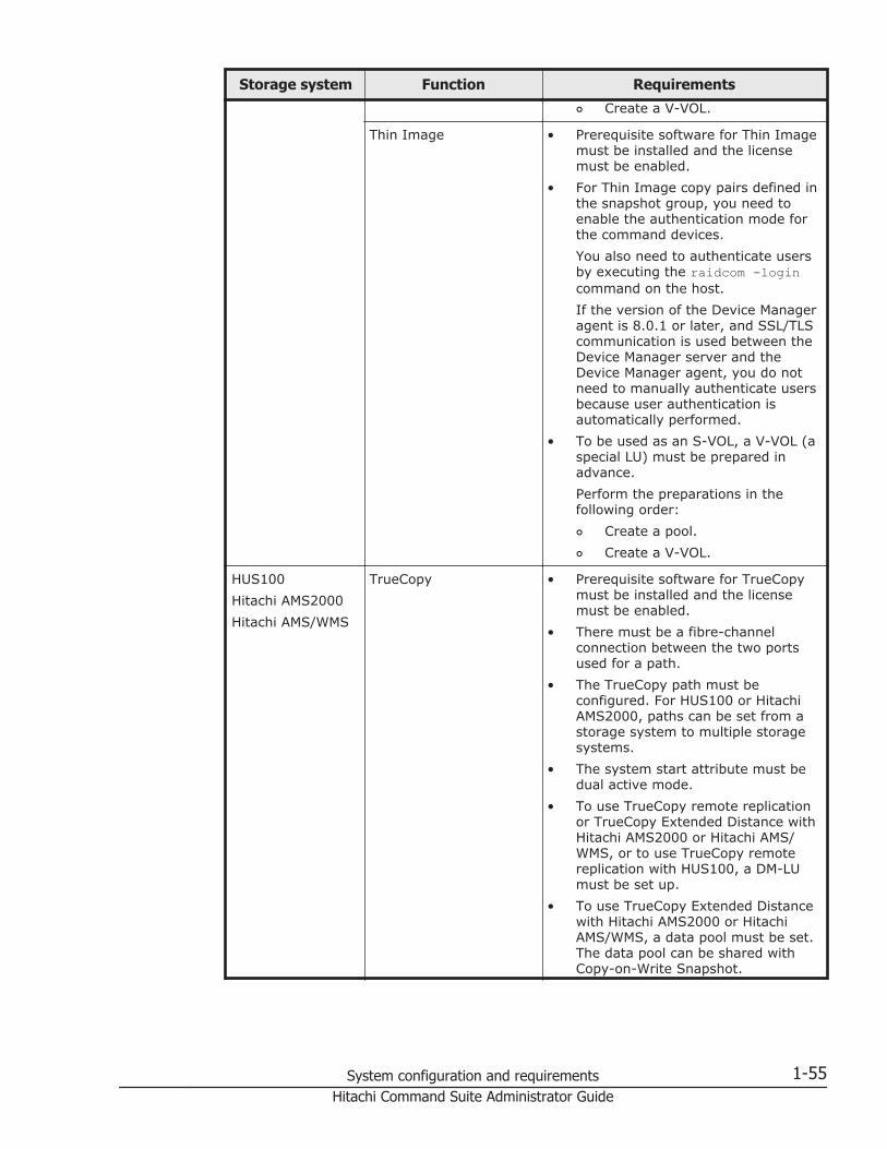
Storage system Function Requirements¢ Create a V-VOL.
Thin Image • Prerequisite software for Thin Imagemust be installed and the licensemust be enabled.
• For Thin Image copy pairs defined inthe snapshot group, you need toenable the authentication mode forthe command devices.You also need to authenticate usersby executing the raidcom -logincommand on the host.If the version of the Device Manageragent is 8.0.1 or later, and SSL/TLScommunication is used between theDevice Manager server and theDevice Manager agent, you do notneed to manually authenticate usersbecause user authentication isautomatically performed.
• To be used as an S-VOL, a V-VOL (aspecial LU) must be prepared inadvance.Perform the preparations in thefollowing order:¢ Create a pool.¢ Create a V-VOL.
HUS100Hitachi AMS2000Hitachi AMS/WMS
TrueCopy • Prerequisite software for TrueCopymust be installed and the licensemust be enabled.
• There must be a fibre-channelconnection between the two portsused for a path.
• The TrueCopy path must beconfigured. For HUS100 or HitachiAMS2000, paths can be set from astorage system to multiple storagesystems.
• The system start attribute must bedual active mode.
• To use TrueCopy remote replicationor TrueCopy Extended Distance withHitachi AMS2000 or Hitachi AMS/WMS, or to use TrueCopy remotereplication with HUS100, a DM-LUmust be set up.
• To use TrueCopy Extended Distancewith Hitachi AMS2000 or HitachiAMS/WMS, a data pool must be set.The data pool can be shared withCopy-on-Write Snapshot.
System configuration and requirements 1-55Hitachi Command Suite Administrator Guide

Storage system Function Requirements
• To use TrueCopy Extended Distancewith HUS100, a DP pool must becreated. Specify settings so thatmanagement data and differentialdata are stored in the same DP pool.The DP pool can be shared withCopy-on-Write Snapshot.
ShadowImage • Prerequisite software forShadowImage must be installed andthe license must be enabled.
• The system start attribute must bedual active mode.
• For HUS100, Hitachi AMS2000, orHitachi AMS/WMS, a DM-LU must beset up.
Copy-on-Write Snapshot • Prerequisite software for Copy-on-Write Snapshot must be installedand the license must be enabled.
• To be used as an S-VOL, a V-VOL (aspecial LU) must be prepared inadvance.Perform the preparations in thefollowing order:For HUS100a. Create a DP pool.
Specify settings so thatmanagement data anddifferential data are stored inthe same DP pool.The DP pool can be shared withTrueCopy Extended Distance DPpools.
b. Create a V-VOL.For Hitachi AMS2000 or HitachiAMS/WMSa. Create a data pool.
The data pool can be sharedwith TrueCopy ExtendedDistance data pools.
b. Create a V-VOL.• For Hitachi AMS2000, or Hitachi
AMS/WMS, a DM-LU must be set up.
Hitachi SMS ShadowImage • Prerequisite software forShadowImage must be installed andthe license must be enabled.
• The system start attribute must bethe dual active mode.
• A DM-LU must be set up.
1-56 System configuration and requirementsHitachi Command Suite Administrator Guide

Storage system Function Requirements
Copy-on-Write Snapshot • Prerequisite software for Copy-on-Write Snapshot must be installedand the license must be enabled.
• To be used as an S-VOL, a V-VOL (aspecial LU) must be prepared inadvance.Perform the preparations in thefollowing order:¢ Create a data pool.¢ Create a V-VOL.
• A DM-LU must be set up.
#1:For mainframe volume copy pairs, you can only check the configurationby using the Device Manager CLI. There are no storage systemrequirements for checking the copy pair configuration by using the DeviceManager CLI.
#2:The settings specified in TrueCopy can be shared with UniversalReplicator. However, in Universal Replicator, the settings must bespecified for both storage systems used for the P-VOL and the S-VOL.
Caution:
• After the storage system has been configured as required, the storagesystem must be refreshed. Make sure that the latest information isdisplayed before performing operations on copy pairs.
• The storage system serial numbers managed by Device Manager must allbe unique. In the case of TrueCopy or Universal Replicator, remotestorage systems that are not managed by Device Manager must also haveunique serial numbers.
• If you use VSP G1000, Virtual Storage Platform, or HUS VM logical unitsto create a copy pair, do not use logical units associated with a devicegroup.
Related topics
• System configuration for using the local management method to managecopy pairs on page 1-36
• System configuration for using the central management method tomanage copy pairs on page 1-40
• System configuration for using a virtual command device serverconfiguration to manage copy pairs on page 1-44
• System configuration for using an SVP configuration to manage copy pairs(when copy pairs are defined in a configuration definition file) on page1-48
System configuration and requirements 1-57Hitachi Command Suite Administrator Guide

• System configuration for using an SVP configuration to manage copy pairs(when copy pairs are defined as a device group) on page 1-50
Prerequisite version of the Device Manager agent formanaging copy pairs
The prerequisite version of the Device Manager agent varies depending onthe storage system to be managed and the program to be used.
When using the GUI to manage copy pairs
The prerequisite version of the Device Manager agent varies depending onthe target storage system.
Table 1-7 Device Manager agent requirements for managing copy pairs byusing the GUI
Storage system Device Manager agent version
VSP G1000 8.0 or later
Virtual Storage Platform 7.0 or later
Universal Storage Platform V/VM 6.0 or later
Hitachi USP 6.0 or later
HUS VM 7.3.1 or later
HUS100 7.2.0 or later
Hitachi AMS2000 6.0 or later
Hitachi SMS 6.0 or later
Hitachi AMS/WMS 6.0 or later
When using the CLI to manage copy pairs
The prerequisite version of the Device Manager agent varies depending onthe program, operations to be performed, and the model of the targetstorage system.
Table 1-8 Device Manager agent requirements for managing copy pairs byusing the CLI
Program Operation from Device ManagerDevice Manageragent version#
Universal Replication Display the status 4.0 or later
Display the status (3DR) 5.5 or later
Change the status 5.6 or later
Change the status (3DR) 5.5 or later
1-58 System configuration and requirementsHitachi Command Suite Administrator Guide

Program Operation from Device ManagerDevice Manageragent version#
TrueCopy Display the status 2.3 or later
Display the status (TrueCopy ExtendedDistance)
5.1 or later
Change the status 2.4 or later
Change the status (TrueCopyExtended Distance)
5.1 or later
Simple Data Recovery Display the status 6.0 or later
ShadowImage Display the status 2.3 or later
Display the status (maximum 1:3) 5.5 or later
Change the status 2.4 or later
Change the status (maximum 1:3) 5.5 or later
Copy-on-Write Snapshot Display the status 4.1 or later
Change the status 4.1 or later
Thin Image Display the status 7.4.0 or later
Change the status 7.6.1 or later
Note:To create a configuration definition file, Device Manager agent version 3.1or later must be installed on each host.
#:The following table lists the Device Manager agent version required foreach storage system model.
Table 1-9 Device Manager agent version required for each storage systemmodel when managing copy pairs by using the CLI
Storage system model Device Manager agentversion
VSP G1000 8.0 or later
Hitachi Virtual Storage Platform 7.0 or later
Hitachi Universal Storage Platform V 5.7 or later
Hitachi Universal Storage Platform VM 5.8 or later
Hitachi Universal Storage Platform 3.5 or later
Hitachi Network Storage Controller 4.0 or later
Hitachi Unified Storage VM 7.3.1 or later
Hitachi Unified Storage 150 7.2.0 or later
Hitachi Unified Storage 130
System configuration and requirements 1-59Hitachi Command Suite Administrator Guide

Storage system model Device Manager agentversion
Hitachi Unified Storage 110
Hitachi Adaptable Modular Storage AMS2500 (H/W Rev.0100)
6.0 or later
Hitachi Adaptable Modular Storage AMS2300 (H/W Rev.0100)
Hitachi Adaptable Modular Storage AMS2100 (H/W Rev.0100)
Hitachi Adaptable Modular Storage AMS2500 (H/W Rev.0200)
6.4 or later
Hitachi Adaptable Modular Storage AMS2300 (H/W Rev.0200)
Hitachi Adaptable Modular Storage AMS2100 (H/W Rev.0200)
Hitachi Adaptable Modular Storage AMS2010
Hitachi Simple Modular Storage 100 6.0 or later
Hitachi Simple Modular Storage 110 6.1 or later
Hitachi Adaptable Modular Storage 1000 5.0 or later
Hitachi Adaptable Modular Storage 500 4.2 or later
Hitachi Adaptable Modular Storage 200
Hitachi Workgroup Modular Storage 100 4.1 or later
Related topics
• System configuration for using the local management method to managecopy pairs on page 1-36
• System configuration for using the central management method tomanage copy pairs on page 1-40
• System configuration for using a virtual command device serverconfiguration to manage copy pairs on page 1-44
• System configuration for using an SVP configuration to manage copy pairs(when copy pairs are defined in a configuration definition file) on page1-48
• System configuration for using an SVP configuration to manage copy pairs(when copy pairs are defined as a device group) on page 1-50
Notes on managing copy pairsNote the following when managing copy pairs:
1-60 System configuration and requirementsHitachi Command Suite Administrator Guide

When using CCI 01-32-03/XX or later
For CCI 01-32-03/XX or later, you cannot specify pair definitions for bothvirtual IDs and physical IDs in one configuration definition file. You need toseparately define virtual ID pairs in the configuration file for virtual IDs, andphysical ID pairs in the configuration definition file for physical IDs.
Follow the rules below to create a configuration definition file for virtual IDsand a configuration definition file for physical IDs:
• The HORCM_VCMD parameter cannot be defined in a configuration definitionfile for physical IDs.
• The HORCM_VCMD parameter can be defined in a configuration definition filefor virtual IDs.
• The HORCM_DEV parameter cannot be defined in a configuration definitionfile for virtual IDs.
• Define pairs for storage systems that do not support virtual storagemachines in a configuration definition file for physical IDs.
• You cannot define command devices for multiple storage systems in aconfiguration definition file for virtual IDs. Individually create aconfiguration definition file for virtual IDs for each storage system.
If you upgraded from CCI 01-32-03/XX or earlier and the above rules are notfollowed, you need to manually recreate the existing configuration definitionfiles.
For details about configuration definition files, see Configuration definition filefor managing copy pairs on page 10-29.
In a configuration where virtual IDs are used to make serialnumbers overlap among storage systems in VSP G1000
• If you are using CCI 01-32-03/XX or earlier, connect the commanddevices for each storage system to different hosts.
• If you are using CCI 01-32-03/XX or later, use different hosts to managethe configuration files that meet either of the following conditions:
¢ The serial number defined for HORCM_VCMD in the configurationdefinition file for virtual IDs matches a serial number defined in theconfiguration definition file for physical IDs
¢ Multiple configuration definition files for virtual IDs exist, and thesame serial number is defined for HORCM_VCMD
If you migrated data by using virtual storage machines in VSPG1000
• Except when using the global-active device functionality, if you want tooperate virtual volumes by using physical IDs, copy pairs must beconfigured in such a way that they are managed with the centralmanagement method.
System configuration and requirements 1-61Hitachi Command Suite Administrator Guide

• The configuration definition file must be recreated to match the newenvironment after migration.
¢ If the CCI version is earlier than 01-32-03/XX, you can specify eithera virtual ID or a physical ID for Serial#, devNum, and portName of theHORCM_LDEV parameter.
¢ If the CCI version is 01-32-03/XX or later, you need to separatelydefine virtual ID pairs in the configuration file for virtual IDs, andphysical ID pairs in the configuration definition file for physical IDs.
¢ For the HORCM_CMD parameter, specify the command devices whosestorage system resource group ID is 0 (resource pools of the defaultvirtual storage machine).
• Enable the authentication mode for the command devices if the microcodeversion of VSP G1000 is earlier than 80-02-01-XX/XX.If the microcode version for VSP G1000 is 80-02-01-XX/XX or later,operations can be performed for copy pairs by using a virtual storagemachine volume, even if the authentication mode for the command deviceis disabled. However, when a command device with authentication modeenabled and a command device with authentication mode disabled bothexist in VSP G1000, and are connected to the same host, authenticationmode must be enabled for all the command devices recognized by thesame host.A command device with its authentication mode enabled must beconnected to the host in the following cases:
¢ When managing the Thin Image pairs defined in the snapshot group.¢ When managing global-active device pairs.¢ When managing pairs within the resource group by using something
other than a virtual storage machine.• User authentication must be completed for all command devices whose
storage system resource group ID is 0 (meta_resource).If the version of the Device Manager agent is 8.0.1 or later, and SSL/TLScommunication is used between the Device Manager server and theDevice Manager agent, you do not need to manually authenticate usersbecause user authentication is automatically performed.
If you migrated data by using virtual IDs in Virtual Storage Platformor HUS VM
• Copy pairs must be configured in such a way that they are managed withthe central management method.
• The configuration definition file must be recreated to match the newenvironment after migration.
¢ Specify the physical ID for Serial# of the HORCM_LDEV parameter.¢ For the HORCM_CMD parameter, specify the command devices whose
storage system resource group ID is 0 (meta_resource).• Enable the authentication mode for the command devices.
1-62 System configuration and requirementsHitachi Command Suite Administrator Guide

• User authentication must be completed for all command devices whosestorage system resource group ID is 0 (meta_resource).If the version of the Device Manager agent is 8.0.1 or later, and SSL/TLScommunication is used between the Device Manager server and theDevice Manager agent, you do not need to manually authenticate usersbecause user authentication is automatically performed.
If you use Device Manager to manage copy pairs that were createdby using a management tool other than Device Manager
• When the copy pair is created by using Storage Navigator, SVP, orCCI/LIBYou need to perform either of the following:
¢ Manually create a configuration definition file to define the copy pair.¢ Dissolve the copy pair by using the management tool that was used
when creating the copy pair, and then create a copy pair by usingDevice Manager.
• When the copy pair is a Thin Image copy pair defined in a copy groupIf you manage copy pairs of 65 generations or more from the DeviceManager GUI, delete the existing copy group, and then create a copy pairby using a snapshot group.If you manage the copy pair from the Device Manager CLI, dissolve thecopy pair by using the management tool that was used when creating thecopy pair, and then create a copy pair from the Device Manager CLI.
If you changed the server.horcmconfigfile.hostname value inthe server.properties file of the Device Manager server
In the following cases, you need to modify the configuration definition filebecause copy pairs will no longer be able to be managed from DeviceManager:
• If the IP address of the host was changed when ipaddress is set for theserver.horcmconfigfile.hostname property in the server.propertiesfile of the Device Manager server
• If the host name was changed when hostname is set for theserver.horcmconfigfile.hostname property in the server.propertiesfile of the Device Manager server
To modify the configuration definition file, perform the following procedure:
1. Modify the configuration definition file of the local host.2. Restart the Device Manager agent on the local host.3. Modify the configuration definition file of the remote host.4. Refresh the storage systems.
System configuration and requirements 1-63Hitachi Command Suite Administrator Guide

If you use Device Manager to control copy pairs that are managedby using CCI or Protection Manager
The configuration definition file on the host that manages the P-VOL of thecopy pair and the configuration definition file on the host that manages the S-VOL of the copy pair must have the same group name and the same pairname. If different names are specified, Device Manager cannot control thatcopy pair. In addition, if you want to use a single host to manage multiplecopy pairs, make sure that these copy pairs satisfy the conditions writtenbelow. If there are copy pairs that do not satisfy the conditions, modify theconfiguration definition file.
• If the version of the Device Manager agent installed on the host is 05-60or earlier:Each copy pair on the host must have a unique combination of thefollowing items:Group namePair name
• If the version of the Device Manager agent installed on the host is 05-70or later:Each copy pair on the host must have a unique combination of thefollowing items:Port numberGroup namePair name
If you use configuration definitions files that were created by usingDevice Manager CLI in CCI
If you want to create a copy pair by using CCI or if CCI is already being usedto manage copy pairs, you can use the Device Manager CLI to create aconfiguration definition file.
• You cannot use Device Manager to create copy pairs from configurationdefinition files created in the Device Manager CLI.
• To create copy pairs in CCI from configuration definition files created inthe Device Manager CLI, you must change the MU numbers to appropriatevalues.
• If you have created an invalid configuration definition file by using theDevice Manager, you cannot delete the file from Device Manager. To dothis, you need to delete or edit the configuration definition file on the hostmanaging the copy pairs. An invalid configuration file or a configurationfile that is not used for performing copy pair operations might affectsystem performance (for example, when adding or refreshing a storagesystem). Delete such configuration files from the host that manages copypairs.
Related topics
• Managing copy pairs on page 10-7
1-64 System configuration and requirementsHitachi Command Suite Administrator Guide

• server.horcmconfigfile.hostname on page A-9
Configuring a high availability systemIn Device Manager, you can configure a high availability system byduplicating data on two units of the storage system (VSP G1000) by usingglobal-active device functionality and then making it possible to receive I/Ofrom both units of the storage system.
Example of a configuration for configuring a high availability systemThe following figure shows an example of a system configuration forconfiguring a high availability system.
System configuration and requirements 1-65Hitachi Command Suite Administrator Guide
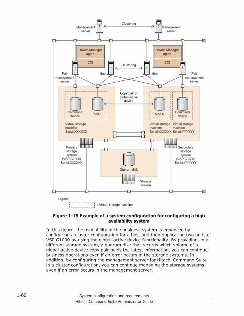
Figure 1-18 Example of a system configuration for configuring a highavailability system
In this figure, the availability of the business system is enhanced byconfiguring a cluster configuration for a host and then duplicating two units ofVSP G1000 by using the global-active device functionality. By providing, in adifferent storage system, a quorum disk that records which volume of aglobal-active device copy pair holds the latest information, you can continuebusiness operations even if an error occurs in the storage systems. Inaddition, by configuring the management server for Hitachi Command Suitein a cluster configuration, you can continue managing the storage systemseven if an error occurs in the management server.
1-66 System configuration and requirementsHitachi Command Suite Administrator Guide

Requirements for configuring a high availability systemConfigure the management server, pair management server, and storagesystems so that the following conditions are satisfied.
Management server conditions:
• The Replication Manager license must be registered.• The following computers must be registered as the Device Manager
management resources:
¢ A host that recognizes the P-VOL and the S-VOL¢ The primary site pair management server¢ The secondary site pair management server¢ The primary site storage system¢ The secondary site storage system¢ An external storage system used for quorum disks
Host (application servers) conditions:
• Path management software must be installed.
Note: If the host OS is HP-UX 11i v3 and you are using the native multi-pathing features, execute the following command in advance to disable themulti-pathing features for legacy device special files:scsimgr save_attr -a leg_mpath_enable=false
Storage system conditions (common to the primary and secondarysites):
• Both the primary site and secondary site storage systems must be VSPG1000.
• The prerequisite software for global-active device must be installed andthe license must be enabled.
• The primary site and secondary site storage systems must be connectedvia two or more Fibre Channels, and a bidirectional remote path must beset between the primary site and secondary site storage systems.
• An external volume for quorum disk must exist on both the primary siteand secondary site storage systems, and the same quorum disk ID mustbe set.
• There must be sufficient space in the storage system's cache and sharedmemory.
For details about prerequisite software, caches, or shared memory, see theglobal-active device documentation.
System configuration and requirements 1-67Hitachi Command Suite Administrator Guide

Conditions for external storage systems used for quorum disks
• There must be fibre-channel connections between the primary sitestorage system and the external storage system used for quorum disks,and between the secondary site storage system and the external storagesystem used for quorum disks.
• External paths must be set between the external port of the primary sitestorage system and the port of the external storage system used forquorum disks, and between the external port of the secondary sitestorage system and the port of the external storage system used forquorum disks.
Pair management server conditions (common to the primary andsecondary sites):
• Device Manager agent version 8.0.1 or later must be installed on the pairmanagement server.
• CCI version 01-32-03/XX or later must be installed on the pairmanagement server.For instructions on how to install CCI, see the CCI documentation.
• If there are multiple NICs on the pair management server, the DeviceManager agent and CCI must use the same IP address.
Pair volume conditions:
• The P-VOL and S-VOL must be managed by a single management server(Device Manager server).
• The P-VOL and S-VOL must be recognized by the hosts (applicationservers).
• Both the P-VOL and S-VOL must be HDP volumes or HDT volumes.• Both the P-VOL and S-VOL must be opened volumes.• The model name and serial number of the virtual storage machine that
the P-VOL belongs to must be the same as the model name and serialnumber of the virtual storage machine that the S-VOL belongs to.
Command device conditions:
• The command device security must not be set.• Command devices must belong to the default virtual storage machine.• When managing partitioned resources in the storage system, the host
(pair management server) must be connected to the command deviceswhose storage system resource group ID is 0 (resource pools of thedefault virtual storage machine), and the information of the commanddevices is defined in the rgcmddev.properties file of the Device Manageragent.
• The authentication mode for the command device is enabled.
1-68 System configuration and requirementsHitachi Command Suite Administrator Guide

• User authentication for the storage system is completed beforeperforming operations on global-active device copy pairs from the DeviceManager GUI or CLI.If SSL/TLS communication is used between the Device Manager serverand the Device Manager agent, you do not need to manually authenticateusers because user authentication is automatically performed.
Tip: The default virtual storage machine is a virtual storage machine thatsatisfies both of the following conditions:
• The model name of the virtual storage machine is the same as the modelname of the storage system that the virtual storage machine belongs to.
• The serial number of the virtual storage machine is the same as the serialnumber of the storage system that the virtual storage machine belongsto.
Caution: When creating global-active device copy pairs in a volume wheredata is migrated by using the nondisruptive migration functionality, thefollowing requirements must also be satisfied:
• The microcode version of both the primary and secondary storagesystems (VSP G1000) must be 80-02-01-XX/XX or later.
• The version of Device Manager agent must be 8.1 or later.• The volume does not have data that is being migrated by using the
nondisruptive migration functionality.
For details about remote path settings, pair management server settings,quorum disk settings, or virtual storage machines, see the Hitachi CommandSuite User Guide or Hitachi Command Suite CLI Reference Guide.
Related topics
• Properties for command devices connected to Device Manager agent(rgcmddev.properties file) on page D-23
Notes on executing commandsIn Windows, if the User Account Control (UAC) function is enabled, you mustopen a command prompt window as a member of the Administrators group inorder to execute commands.
System configuration and requirements 1-69Hitachi Command Suite Administrator Guide

1-70 System configuration and requirementsHitachi Command Suite Administrator Guide

2Network configuration
This chapter describes the settings for the Hitachi Command Suite productsthat are required in various network configurations.
□ Ports used by Hitachi Command Suite products
□ Changing ports used by Common Component
□ Registering firewall exceptions for Device Manager and Tiered StorageManager
□ Registering firewall exceptions for Host Data Collector (Windows)
□ Network settings with multiple IP addresses
□ Device Manager settings in IPv6 environments
□ Changing the IP address or host name of the management server
□ Changing the URL for accessing Hitachi Command Suite products(hcmds64chgurl command)
Network configuration 2-1Hitachi Command Suite Administrator Guide

Ports used by Hitachi Command Suite productsAvoid specifying port numbers used by other programs installed on the samecomputer for the port numbers used by Hitachi Command Suite products.
If the same port number is set, either change the setting for the otherprogram or change the setting for the Hitachi Command Suite product.
Tip: Some port numbers are part of the port numbers that are temporarilyassigned by OSs. If the port numbers used by the Hitachi Command Suiteproducts are set in the services file of the OS, the port numbers can beexcluded from the port numbers that can be temporarily assigned by the OS.
Ports used by Common ComponentFor the management server, ensure that the port numbers specified for useby Common Component are different from the port numbers used by otherprograms installed on the same computer.
Table 2-1 Ports used by Common Component
Port number Description
22015/tcp# Used for accessing the HBase 64 Storage Mgmt Web Servicewhen communicating with management clients (GUI).This port number can be changed.
22016/tcp Used for accessing the HBase 64 Storage Mgmt Web Servicewhen performing SSL communication with management clients(GUI).This port number can be changed.
22017/tcp Used internally for Common Component communication(communication with the Web server).This port number can be changed.
22018/tcp Used internally for Common Component communication(receiving a termination message from the Web server).This port number can be changed.
22019/tcp to22024/tcp
Used when Tuning Manager is installed.This port number can be changed.
22025/tcp Used internally for Common Component communication(communication with the Web server).This port number can be changed.
22026/tcp Used internally for Common Component communication(receiving a termination message from the Web server).This port number can be changed.
22027/tcp22028/tcp
Used when Compute Systems Manager is installed.This port number can be changed.
22029/tcp22030/tcp
Reserved by Common Component.
2-2 Network configurationHitachi Command Suite Administrator Guide

Port number Description
22031/tcp Used internally for Common Component communication (singlesign-on).This port number can be changed.
22032/tcp Used internally for Common Component communication (HiRDB).This port number can be changed.
22033/tcp Used internally for Common Component communication(communication with the Web server).This port number can be changed.
22034/tcp Used internally for Common Component communication(receiving a termination message from the Web server).This port number can be changed.
#:This port is also used when SSL is enabled. To interrupt non-SSLcommunication from outside the network to the management server, youneed to edit the user_httpsd.conf file.
Related topics
• Changing ports used by Common Component on page 2-10• Registering firewall exceptions for Device Manager and Tiered Storage
Manager on page 2-15• Editing the user_httpsd.conf file on page 4-36• How to change the ports when Tuning Manager and Compute Systems
Manager are installed: The manual for each product
Ports used by the Device Manager serverFor the management server, ensure that the port numbers specified for useby the Device Manager server are different from the port numbers used byother programs installed on the same computer.
Table 2-2 Ports used by the Device Manager server
Port number Description
162/udp Used for receiving SNMP traps from storage systems (VSP G1000,Virtual Storage Platform, Universal Storage Platform V/VM, HitachiUSP, and HUS VM) and file servers (Hitachi Data Ingestor andHitachi NAS Platform F).You cannot change the settings by using Device Manager. Ifproducts using these ports are installed on the same computer,change the settings of those products.
427/tcp Used for communication with a CIM client (service discovery).
Network configuration 2-3Hitachi Command Suite Administrator Guide

Port number Description
You cannot change the settings by using Device Manager. Ifproducts using these ports are installed on the same computer,change the settings of those products.
2001/tcp# Used internally for Device Manager server communication, forcommunication with management clients (via the GUI or the CLI),for communication with storage systems, and for communicationwith hosts (Device Manager agents and file servers).Note that the Device Manager server cannot start if this port isbeing used by another product.You can change this port number by modifying theserver.http.port property in the server.properties file of theDevice Manager server.
2443/tcp Used internally for Device Manager server communication and forSSL communication with management clients (via the GUI or theCLI).You can change this port number by modifying theserver.https.port property in the server.properties file ofthe Device Manager server.
5983/tcp Used for receiving event indications from SMI-S providers.You can change this port number by modifying theserver.smisclient.indication.port property in theserver.properties file of the Device Manager server.
5988/tcp Used for non-SSL communication with a CIM client (Objectoperation).This port number can be changed.
5989/tcp Used for SSL communication with a CIM client (Object operation).This port number can be changed.
23055/tcp Used internally for Device Manager server communication.You can change this port number by modifying theserver.rmi.port property in the server.properties file of theDevice Manager server.
24230/tcp Used by HiRDB.You can change this port number by using the htmsetupcommand.
Any/tcp Used for communication with View Server of Tuning Manager.By default, any free port numbers are used.You might want to change the setting to use a specific portnumber if, for example, a firewall is set up between the TuningManager management server and the Device Managermanagement server. In such cases, register the port number forthe ownPort parameter in the config.xml andconfigforclient.xml files.
#:This port is also used when SSL is enabled. If you want to permit onlySSL communication, set up a firewall.
2-4 Network configurationHitachi Command Suite Administrator Guide

Related topics
• Registering firewall exceptions for Device Manager and Tiered StorageManager on page 2-15
• Specifying the settings for remote connection to the Tuning Managerserver and the port number (htmsetup command) on page 5-18
• Setting up the config.xml and configforclient.xml files on page 5-19• Changing CIM/WBEM port numbers on page 7-6• Changing Device Manager server properties on page A-4• server.http.port on page A-6• server.https.port on page A-7• server.rmi.port on page A-8• server.smisclient.indication.port on page A-15
Ports used by the Tiered Storage Manager serverFor the management server, ensure that the port numbers specified for useby the Tiered Storage Manager server are different from the port numbersused by other programs installed on the same computer.
Table 2-3 Ports used by the Tiered Storage Manager server
Port number Description
20352/tcp Used for communication with management clients.You can change the port by modifying the server.rmi.portproperty in the server.properties file of the Tiered StorageManager server.
24500/tcp Used for SSL communication with management clients.You can change the port by modifying theserver.rmi.security.port property in the server.propertiesfile of the Tiered Storage Manager server.
Related topics
• Changing Tiered Storage Manager server properties on page B-2• server.rmi.port on page B-4• server.rmi.security.port on page B-4
Ports used by Host Data CollectorFor the computer on which Host Data Collector is installed, ensure that theport numbers specified for use by Host Data Collector are different from theport numbers used by other programs installed on the same computer.
Network configuration 2-5Hitachi Command Suite Administrator Guide

Table 2-4 Ports used by Host Data Collector
Port number Description
22098/tcp Used for internal communication by Host Data Collector and fornon-SSL communication between the Device Manager server andthe RMI registry.You can change the port by using thehdc.common.rmi.registryPort property in thehdcbase.properties file of Host Data Collector.
22099/tcp Used for non-SSL communication between the Device Managerserver and the RMI server.You can change the port by using thehdc.common.rmi.serverPort property in thehdcbase.properties file of Host Data Collector.
22100/tcp Used for non-SSL communication between the Device Managerserver and the class loader.You can change the port by using thehdc.common.http.serverPort property in thehdcbase.properties file of Host Data Collector.
22104/tcp Used for SSL communication between the Device Manager serverand the RMI registry.You can change the port by using thehdc.common.rmi.ssl.registryPort property in thehdcbase.properties file of Host Data Collector.
22105/tcp Used for SSL communication between the Device Manager serverand the RMI server.You can change the port by using thehdc.common.rmi.ssl.serverPort property in thehdcbase.properties file of Host Data Collector.
22106/tcp Used for SSL communication between the Device Manager serverand the class loader.You can change the port by using thehdc.common.https.serverPort property in thehdcbase.properties file of Host Data Collector.
22110/tcp Used for communication between the Service process and theAdapter process.You can change the port by using the hdc.service.localportproperty in the hdcbase.properties file of Host Data Collector.
22111/tcp to22120/tcp
Used for communication between the Service process and theAdapter process.You can change these ports by using the hdc.adapter.localportproperty in the hdcbase.properties file of the Host DataCollector.
Related topics
• Changing Host Data Collector properties on page C-2• hdc.service.localport on page C-3
2-6 Network configurationHitachi Command Suite Administrator Guide

• hdc.adapter.localport on page C-3• hdc.common.rmi.registryPort on page C-3• hdc.common.rmi.serverPort on page C-4• hdc.common.http.serverPort on page C-4• hdc.common.rmi.ssl.registryPort on page C-5• hdc.common.rmi.ssl.serverPort on page C-5• hdc.common.https.serverPort on page C-6
Ports used by the Device Manager agentFor the computer on which the Device Manager agent is installed, ensure thatthe port numbers specified for use by the Device Manager agent are differentfrom the port numbers used by other programs installed on the samecomputer.
Table 2-5 Ports used by Device Manager agent
Port number Description
24041/tcp Used for communication with the Device Manager server.You can change the port by using the server.agent.portproperty in the server.properties file of the Device Manageragent.
24042/tcp Used for communication with the Device Manager server.You can change the port by using the server.http.port propertyin the server.properties file of the Device Manager agent.
24043/tcp Used internally for Device Manager agent communication.You can change the port by using the server.http.localPortproperty in the server.properties file of the Device Manageragent.
Related topics
• Changing Device Manager agent properties on page D-2• server.agent.port on page D-11• server.http.localPort on page D-11• server.http.port on page D-11
Ports used by storage systemsTo use Device Manager and Tiered Storage Manager to manage storagesystems, you need to provide ports for communication with the managementserver and management clients (GUI).
Network configuration 2-7Hitachi Command Suite Administrator Guide

Table 2-6 Ports used by storage systems
Target storagesystem Port number Description
VSP G1000Virtual StoragePlatform
80/tcp Used for communication with managementclients (GUI).This port number cannot be changed.
443/tcp Used for starting Storage Navigator by SSLfrom management clients (GUI) .This port number cannot be changed.
1099/tcp Used for communication with themanagement server or management clients(GUI).This port number cannot be changed.
51099/tcp Used for communication with themanagement server or management clients(GUI).This port number cannot be changed.
51100/tcp Used for communication with themanagement server or management clients(GUI).This port number cannot be changed.
Universal StoragePlatform V/VM
80/tcp Used for communication with managementclients (GUI).This port number cannot be changed.
443/tcp Used for starting Element Manager by SSLfrom management clients (GUI) .This port number cannot be changed.
1099/tcp Used for communication with themanagement server or management clients(GUI).This port number cannot be changed.
51099/tcp Used for communication with themanagement server or management clients(GUI).This port number cannot be changed.
51100/tcp Used for communication with themanagement server or management clients(GUI).This port number cannot be changed.
Hitachi USP 80/tcp Used for communication with managementclients (GUI).This port number cannot be changed.
443/tcp Used for starting Element Manager by SSLfrom management clients (GUI).This port number cannot be changed.
2-8 Network configurationHitachi Command Suite Administrator Guide

Target storagesystem Port number Description
1099/tcp Used for communication with themanagement server or management clients(GUI).This port number cannot be changed.
51099/tcp Used for communication with themanagement server or management clients(GUI).This port number cannot be changed.
HUS VM 80/tcp Used for communication with managementclients (GUI).This port number cannot be changed.
443/tcp Used for starting Element Manager by SSL.This port number cannot be changed.
1099/tcp Used for communication with managementclients (GUI).This port number cannot be changed.
51099/tcp Used for communication with themanagement server.This port number cannot be changed.
51100/tcp Used for communication with themanagement server.This port number cannot be changed.
Hitachi AMS/WMS 2000/tcp Used for communication with themanagement server.This port number can be changed.
28355/tcp Used for communication with themanagement server.This port number can be changed.
Hitachi AMS2000 2000/tcp Used for non-SSL communication with themanagement server.This port number can be changed.
28355/tcp Used for SSL communication with themanagement server.This port number can be changed.
Hitachi SMS 2000/tcp Used for non-SSL communication with themanagement server.This port number can be changed.
28355/tcp Used for SSL communication with themanagement server.This port number can be changed.
HUS100 2000/tcp Used for non-SSL communication with themanagement server.
Network configuration 2-9Hitachi Command Suite Administrator Guide

Target storagesystem Port number Description
This port number can be changed.
28355/tcp Used for SSL communication with themanagement server.This port number can be changed.
If you change the port number (2000/tcp or 28355/tcp) used by a midrangestorage system (HUS100, Hitachi SMS, Hitachi AMS2000, or Hitachi AMS/WMS), you need to specify the new port number in the services file of themanagement server OS. If you operate the midrange storage system withoutdoing so, an error (code: DMEA000006) occurs and operations might fail.
For communication between midrange storage systems and the managementserver (Device Manager server), use the same port number for eachcommunication protocol (SSL and non-SSL) to be used. If communication isbetween midrange storage systems that have different port numbers, anerror might occur if a midrange storage system uses a port number that isdifferent from the one specified in the services file of the managementserver. In addition, even if the midrange storage systems use the same portnumbers as the ones specified in the services file, an error will not occur butthe operation might take a long time.
Related topics
• How to change the port numbers and how to specify entries in theservices file: Documentation for each storage system
Changing ports used by Common ComponentTo change the ports used by Common Component after installing the HitachiCommand Suite products, you need to edit the settings file for CommonComponent.
To change the ports used by Common Component:
1. Stop the services of Hitachi Command Suite products.2. Edit the Common Component settings files and change the port number.3. Start the services of the Hitachi Command Suite products.4. If you change the following port numbers, you need to change the URLs
of all Hitachi Command Suite products that are installed on themanagement server:
¢ 22015/tcp (used for accessing HBase 64 Storage Mgmt Web Service)You need to change the URLs if you use non-SSL for communicationbetween the management server and management clients.
¢ 22016/tcp (used for accessing SSL HBase 64 Storage Mgmt WebService)
2-10 Network configurationHitachi Command Suite Administrator Guide

You need to change the URLs if you use SSL for communicationbetween the management server and management clients.
Note that you might not need to change the URLs depending on thenetwork environment between the management server and managementclients, such as an environment that has a firewall configured.
Table 2-7 Port number settings files for Common Component
Default port number Settings files Location
22015/tcp In Windows:installation-folder-for-Hitachi-Command-Suite\Base64\uCPSB\httpsd\conf\user_httpsd.conf#1
In Linux:installation-directory-for-Hitachi-Command-Suite/Base64/uCPSB/httpsd/conf/user_httpsd.conf#1
Listen
22016/tcp In Windows:installation-folder-for-Hitachi-Command-Suite\Base64\uCPSB\httpsd\conf\user_httpsd.conf#1
In Linux:installation-directory-for-Hitachi-Command-Suite/Base64/uCPSB/httpsd/conf/user_httpsd.conf#1
• VirtualHosthost-name:port-number
• Listen#2
22017/tcp In Windows:installation-folder-for-Hitachi-Command-Suite\Base64\uCPSB\CC\web\redirector\workers.properties
In Linux:installation-directory-for-Hitachi-Command-Suite/Base64/uCPSB/CC/web/redirector/workers.properties
worker.HiCommand64.port
In Windows:installation-folder-for-Hitachi-Command-Suite\Base64\uCPSB\CC\web\containers\HiCommand64\usrconf\usrconf.properties
In Linux:installation-directory-for-Hitachi-Command-Suite/Base64/uCPSB/CC/web/containers/HiCommand64/usrconf/usrconf.properties
webserver.connector.ajp13.port
22018/tcp In Windows: webserver.shutdown.port
Network configuration 2-11Hitachi Command Suite Administrator Guide

Default port number Settings files Locationinstallation-folder-for-Hitachi-Command-Suite\Base64\uCPSB\CC\web\containers\HiCommand64\usrconf\usrconf.properties
In Linux:installation-directory-for-Hitachi-Command-Suite/Base64/uCPSB/CC/web/containers/HiCommand64/usrconf/usrconf.properties
22025/tcp In Windows:installation-folder-for-Hitachi-Command-Suite\Base64\uCPSB\CC\web\redirector\workers.properties
In Linux:installation-directory-for-Hitachi-Command-Suite/Base64/uCPSB/CC/web/redirector/workers.properties
worker.DeviceManagerWebService.port
In Windows:installation-folder-for-Hitachi-Command-Suite\Base64\uCPSB\CC\web\containers\DeviceManagerWebService\usrconf\usrconf.properties
In Linux:installation-directory-for-Hitachi-Command-Suite/Base64/uCPSB/CC/web/containers/DeviceManagerWebService/usrconf/usrconf.properties
webserver.connector.ajp13.port
22026/tcp In Windows:installation-folder-for-Hitachi-Command-Suite\Base64\uCPSB\CC\web\containers\DeviceManagerWebService\usrconf\usrconf.properties
In Linux:installation-directory-for-Hitachi-Command-Suite/Base64/uCPSB/CC/web/containers/DeviceManagerWebService/usrconf/usrconf.properties
webserver.shutdown.port
22031/tcp installation-folder-for-Hitachi-Command-Suite\Base64\uCPSB\httpsd\conf\user_hsso_httpsd.conf
Listen127.0.0.1:port-number
22032/tcp In Windows:installation-folder-for-Hitachi-Command-Suite\Base64\HDB\CONF\emb\HiRDB.ini
PDNAMEPORT
2-12 Network configurationHitachi Command Suite Administrator Guide

Default port number Settings files Location
In Linux:installation-directory-for-Hitachi-Command-Suite/Base64/HDB/conf/emb/HiRDB.ini
In Windows:installation-folder-for-Hitachi-Command-Suite\Base64\HDB\CONF\pdsys
In Linux:installation-directory-for-Hitachi-Command-Suite/Base64/HDB/conf/pdsys
pd_name_port
In Windows:installation-folder-for-Hitachi-Command-Suite\Base64\database\work\def_pdsys
In Linux:installation-directory-for-Hitachi-Command-Suite/Base64/database/work/def_pdsys
pd_name_port
22033/tcp In Windows:installation-folder-for-Hitachi-Command-Suite\Base64\uCPSB\CC\web\redirector\workers.properties
In Linux:installation-directory-for-Hitachi-Command-Suite/Base64/uCPSB/CC/web/redirector/workers.properties
worker.HBase64StgMgmtSSOService.port
In Windows:installation-folder-for-Hitachi-Command-Suite\Base64\uCPSB\CC\web\containers\HBase64StgMgmtSSOService\usrconf\usrconf.properties
In Linux:installation-directory-for-Hitachi-Command-Suite/Base64/uCPSB/CC/web/containers/HBase64StgMgmtSSOService/usrconf/usrconf.properties
webserver.connector.ajp13.port
22034/tcp In Windows:installation-folder-for-Hitachi-Command-Suite\Base64\uCPSB\CC\web\containers\HBase64StgMgmtSSOService\usrconf\usrconf.properties
In Linux:
webserver.shutdown.port
Network configuration 2-13Hitachi Command Suite Administrator Guide

Default port number Settings files Locationinstallation-directory-for-Hitachi-Command-Suite/Base64/uCPSB/CC/web/containers/HBase64StgMgmtSSOService/usrconf/usrconf.properties
#1:Do not edit the httpsd.conf file.
#2:If SSL is enabled, to interrupt non-SSL communication from outside thenetwork to the management server, you need to edit the line Listen22015 in the user_httpsd.conf file.
Note: If you change the port numbers for Common Component, you mighthave to review the following settings depending on the operatingenvironment:
• If Element Manager is used to operate a Hitachi AMS/WMS storagesystem (23015/tcp and 23016/tcp):You need to use launchapptool to modify the URL settings for StorageNavigator Modular 2.
• If performance information is acquired from Tuning Manager (22015/tcpand 22016/tcp):If the Tuning Manager server is installed on the same server, revise thehtnm.server.n.port property settings.
• If Hitachi Data Ingestor or Hitachi NAS Platform F is registered on DeviceManager as the management-target host:You need to report the file server configuration information to the DeviceManager server.On the Edit HDvM Settings dialog box for Hitachi File Services Manager,select Yes for the Send information when the system is refreshedcheck box, and then click OK. Then in the Processing Nodes window, clickthe Refresh Processing Node button.
Related topics
• Ports used by Common Component on page 2-2• Changing the URL for accessing Hitachi Command Suite products
(hcmds64chgurl command) on page 2-41• Editing the user_httpsd.conf file on page 4-36• Changing pop-up blocker settings on page 4-67• Settings for using Element Manager on page 5-3• Starting the Hitachi Command Suite services on page 8-4• Stopping the Hitachi Command Suite services on page 8-5• Changing Device Manager server properties on page A-4
2-14 Network configurationHitachi Command Suite Administrator Guide

• htnm.server.n.port on page A-45• How to specify settings for Hitachi File Services Manager: Documentation
for Hitachi Data Ingestor or Hitachi NAS Platform F
Registering firewall exceptions for Device Manager andTiered Storage Manager
When the ports or processes used by Hitachi Command Suite products areregistered as firewall exceptions, connection to the registered ports orprocesses from outside the network is permitted.
Note: If one of the following conditions exists, the user must manuallyregister the ports used by the management server as firewall exceptions afterinstallation of Hitachi Command Suite: The Windows firewall is enabled afteroperation starts, the management server OS is Linux, or a firewall is set up inthe network connected to the management server.
• In Windows:Add all the components that make up Hitachi Command Suite to thefirewall exceptions list.
• In Linux:Add all the port numbers used by Hitachi Command Suite to the firewallexceptions list.
Port numbers that must be registered as firewall exceptions forDevice Manager and Tiered Storage Manager
In an environment with firewalls set up in the network that connects themanagement server, management clients, and storage systems, you need toregister ports used by Hitachi Command Suite products as firewallexceptions.
• Table 2-8 Port numbers that must be registered as firewall exceptionsbetween the management server and management clients on page 2-16
• Table 2-9 Port numbers that must be registered as firewall exceptionsbetween the management server and storage systems on page 2-17
• Table 2-10 Port numbers that must be registered as firewall exceptionsbetween the management client and storage systems on page 2-19
• Table 2-11 Port numbers that must be registered as firewall exceptionsbetween the management server and a host on page 2-20
• Table 2-12 Port numbers that must be registered as firewall exceptionsbetween the management server and a virtualization server on page2-21
• Table 2-13 Port number that must be registered as an exception to afirewall between the management server and a mainframe host on page2-21
Network configuration 2-15Hitachi Command Suite Administrator Guide

• Table 2-14 Port number that must be registered as an exception to afirewall between the management server and a file server on page 2-21
• Table 2-15 Port numbers that must be registered as firewall exceptionsbetween the Device Manager management server and the TuningManager management server on page 2-22
• Table 2-16 Port number that must be registered as a firewall exceptionbetween the management server and the Host Data Collector computeron page 2-23
• Table 2-17 Port number that must be registered as a firewall exceptionbetween the Host Data Collector computer and a host on page 2-24
• Table 2-18 Port numbers that must be registered as firewall exceptionsbetween the management server and an SMI-S provider on page 2-25
• Table 2-19 Port numbers that must be registered as firewall exceptionsbetween the management server and a CIM client on page 2-25
• Table 2-20 Port numbers that must be registered as firewall exceptionsbetween the management server and a mail server on page 2-26
• Table 2-21 Port numbers that must be registered as firewall exceptionsbetween the management server and an external authentication serveron page 2-27
• Table 2-22 Port numbers that must be registered as firewall exceptionswhen you manage copy pairs by using the pair management server onpage 2-27
Table 2-8 Port numbers that must be registered as firewall exceptionsbetween the management server and management clients
Originator DestinationRemarksPort
number Machine Portnumber Machine
any/tcp Managementclient(GUI or DeviceManager CLI)
2001/tcp# Managementserver
This setting is requiredwhen non-SSLcommunication is used.
any/tcp Managementclient(GUI or DeviceManager CLI)
2443/tcp# Managementserver
This setting is requiredwhen SSL communicationis used.
any/tcp Managementclient(Tiered StorageManager CLI)
20352/tcp# Managementserver
This setting is requiredwhen non-SSLcommunication is used.
any/tcp Managementclient(GUI)
22015/tcp# Managementserver
This setting is requiredwhen non-SSLcommunication is used.
any/tcp Managementclient
22016/tcp# Managementserver
This setting is requiredwhen SSL communicationis used.
2-16 Network configurationHitachi Command Suite Administrator Guide

Originator DestinationRemarksPort
number Machine Portnumber Machine
(GUI)
any/tcp Managementclient(Tiered StorageManager CLI)
24500/tcp# Managementserver
This setting is requiredwhen SSL communicationis used.
#:This port number can be changed.
Table 2-9 Port numbers that must be registered as firewall exceptionsbetween the management server and storage systems
Originator DestinationRemarksPort
number Machine Portnumber Machine
any/udp • VSP G1000• Virtual
StoragePlatform
• UniversalStoragePlatformV/VM
• Hitachi USP• HUS VM
162/udp Managementserver
-
any/tcp Managementserver
443/tcp • VSP G1000• Virtual
StoragePlatform
• HUS VM
-
any/tcp Managementserver
1099/tcp • VSP G1000• Virtual
StoragePlatform
• UniversalStoragePlatformV/VM
• Hitachi USP• HUS VM
-
any/tcp Managementserver
2000/tcp# • HitachiAMS/WMS
-
Network configuration 2-17Hitachi Command Suite Administrator Guide

Originator DestinationRemarksPort
number Machine Portnumber Machine
any/tcp Managementserver
2000/tcp# • HUS100• Hitachi SMS• Hitachi
AMS2000
This setting is requiredwhen non-SSLcommunication is used.
any/tcp • UniversalStoragePlatformV/VM
• Hitachi USP
2001/tcp# Managementserver
Set up the firewall sothat communication canbe established from anyport of the storagesystem to the 2001/tcpport of the managementserver.
any/tcp Managementserver
28355/tcp# • HUS100• Hitachi SMS• Hitachi
AMS2000
This setting is requiredwhen SSL communicationis used.
any/tcp Managementserver
51099/tcp • VSP G1000• Virtual
StoragePlatform
• UniversalStoragePlatformV/VM
• Hitachi USP• HUS VM
-
any/tcp Managementserver
51100/tcp • UniversalStoragePlatformV/VM
This setting is requiredwhen you perform anupgrade installation to aDevice Manager serverversion 6.0.0-00 or later.
any/tcp Managementserver
51100/tcp • VSP G1000• Virtual
StoragePlatform
-
Legend:-: Not applicable
#:This port number can be changed.
2-18 Network configurationHitachi Command Suite Administrator Guide
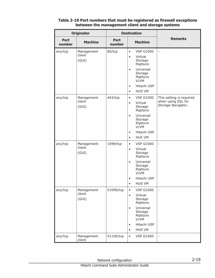
Table 2-10 Port numbers that must be registered as firewall exceptionsbetween the management client and storage systems
Originator DestinationRemarksPort
number Machine Portnumber Machine
any/tcp Managementclient(GUI)
80/tcp • VSP G1000• Virtual
StoragePlatform
• UniversalStoragePlatformV/VM
• Hitachi USP• HUS VM
-
any/tcp Managementclient(GUI)
443/tcp • VSP G1000• Virtual
StoragePlatform
• UniversalStoragePlatformV/VM
• Hitachi USP• HUS VM
This setting is requiredwhen using SSL forStorage Navigator.
any/tcp Managementclient(GUI)
1099/tcp • VSP G1000• Virtual
StoragePlatform
• UniversalStoragePlatformV/VM
• Hitachi USP• HUS VM
-
any/tcp Managementclient(GUI)
51099/tcp • VSP G1000• Virtual
StoragePlatform
• UniversalStoragePlatformV/VM
• Hitachi USP• HUS VM
-
any/tcp Managementclient
51100/tcp • VSP G1000 -
Network configuration 2-19Hitachi Command Suite Administrator Guide

Originator DestinationRemarksPort
number Machine Portnumber Machine
(GUI) • VirtualStoragePlatform
• UniversalStoragePlatformV/VM
• HUS VM
any/tcp Managementclient(GUI)
161/udp VSP G1000 This setting is requiredwhen using themanagement client as anSNMP manager.
any/tcp Managementclient(GUI)
427/tcp VSP G1000 This setting is requiredwhen using SMI-S.
any/tcp Managementclient(GUI)
5989/tcp VSP G1000 This setting is requiredwhen using SMI-S.
any/tcp VSP G1000 162/udp Managementclient(GUI)
This setting is requiredwhen using themanagement client as anSNMP manager.
Legend:-: Not applicable
Table 2-11 Port numbers that must be registered as firewall exceptionsbetween the management server and a host
Originator DestinationRemarksPort
number Machine Portnumber Machine
any/tcp • Normal host• Virtual
machine
2001/tcp# Managementserver
-
any/tcp Managementserver
24041/tcp# • Normal host• Virtual
machine
-
any/tcp Managementserver
24042/tcp# • Normal host• Virtual
machine
-
Legend:-: Not applicable
2-20 Network configurationHitachi Command Suite Administrator Guide

#:This port number can be changed.
Table 2-12 Port numbers that must be registered as firewall exceptionsbetween the management server and a virtualization server
Originator DestinationRemarksPort
number Machine Portnumber Machine
any/tcp Managementserver
443/tcp • VMwareESX
• VMwarevCenterServer thatmanagesVMwareESX
This setting is requiredwhen a virtual WWN isassigned to a virtualmachine by using NPIV.
any/tcp Managementserver
5988/tcp VMware ESX This setting is requiredfor non-SSLcommunication.
any/tcp Managementserver
5989/tcp VMware ESX This setting is requiredfor SSL communication.
Table 2-13 Port number that must be registered as an exception to afirewall between the management server and a mainframe host
Originator DestinationRemarksPort
number Machine Portnumber Machine
any/tcp Managementserver
24042/tcp# Mainframe host -
Legend:-: Not applicable
#:This port number can be changed.
Table 2-14 Port number that must be registered as an exception to afirewall between the management server and a file server
Originator DestinationRemarksPort
number Machine Portnumber Machine
any/tcp • Hitachi DataIngestor
• Hitachi NASPlatform
2001/tcp# Managementserver
-
Network configuration 2-21Hitachi Command Suite Administrator Guide

Originator DestinationRemarksPort
number Machine Portnumber Machine
• Hitachi NASPlatform F
any/tcp Managementserver
8443/tcp Hitachi NASPlatform
This setting is requiredfor firmware versions10.2.3071 and later ofHitachi NAS Platform.
Legend:-: Not applicable
#:This port number can be changed.
Table 2-15 Port numbers that must be registered as firewall exceptionsbetween the Device Manager management server and the Tuning Manager
management server
Originator DestinationRemarksPort
number Machine Portnumber Machine
any/tcp Device Managermanagementserver
22286/tcp#1
Tuning Managermanagementserver
This setting is requiredfor acquiringperformance informationsuch as parity groupusage rate and volumeIOPS from a remotelyconnected TuningManager.
any/tcp Device Managermanagementserver
22900/tcpto22999/tcp
Tuning Managermanagementserver
This setting is requiredfor remotely connectingto Tuning Manager.
any/tcp Tuning Managermanagementserver
22015/tcp#1
Device Managermanagementserver
This setting is requiredfor remotely connectingto Tuning Manager.
any/tcp Tuning Managermanagementserver
24230/tcp#2
Device Managermanagementserver
This setting is requiredfor remotely connectingto Tuning Manager.
any/tcp Tuning Managermanagementserver
1024/tcp to65535/tcp#3
Device Managermanagementserver
This setting is requiredfor acquiringperformance informationsuch as parity groupusage rate and volumeIOPS from a remotelyconnected TuningManager.
Legend:
2-22 Network configurationHitachi Command Suite Administrator Guide
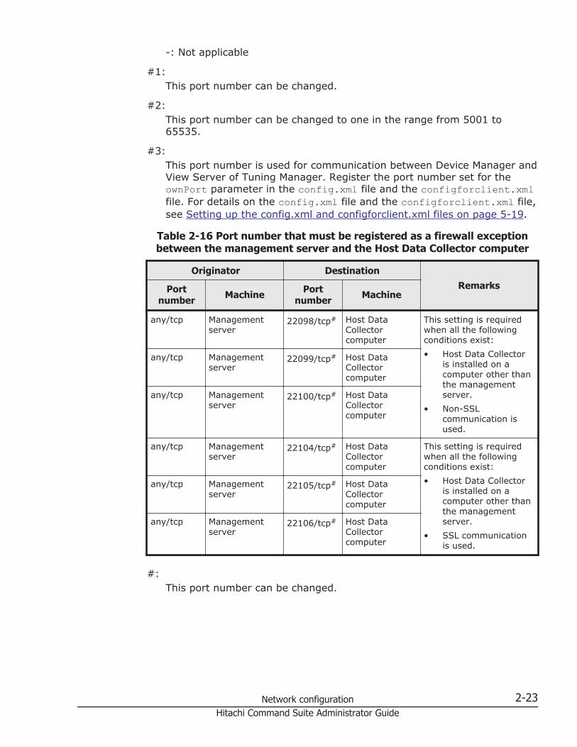
-: Not applicable
#1:This port number can be changed.
#2:This port number can be changed to one in the range from 5001 to65535.
#3:This port number is used for communication between Device Manager andView Server of Tuning Manager. Register the port number set for theownPort parameter in the config.xml file and the configforclient.xmlfile. For details on the config.xml file and the configforclient.xml file,see Setting up the config.xml and configforclient.xml files on page 5-19.
Table 2-16 Port number that must be registered as a firewall exceptionbetween the management server and the Host Data Collector computer
Originator DestinationRemarksPort
number Machine Portnumber Machine
any/tcp Managementserver
22098/tcp# Host DataCollectorcomputer
This setting is requiredwhen all the followingconditions exist:• Host Data Collector
is installed on acomputer other thanthe managementserver.
• Non-SSLcommunication isused.
any/tcp Managementserver
22099/tcp# Host DataCollectorcomputer
any/tcp Managementserver
22100/tcp# Host DataCollectorcomputer
any/tcp Managementserver
22104/tcp# Host DataCollectorcomputer
This setting is requiredwhen all the followingconditions exist:• Host Data Collector
is installed on acomputer other thanthe managementserver.
• SSL communicationis used.
any/tcp Managementserver
22105/tcp# Host DataCollectorcomputer
any/tcp Managementserver
22106/tcp# Host DataCollectorcomputer
#:This port number can be changed.
Network configuration 2-23Hitachi Command Suite Administrator Guide

Table 2-17 Port number that must be registered as a firewall exceptionbetween the Host Data Collector computer and a host
Originator DestinationRemarksPort
number Machine Port number Machine
any/tcp Host DataCollectorcomputer
22/tcp# Normal host This setting is requiredwhen the OS of themanagement-targetnormal host is UNIX.
any/tcp Host DataCollectorcomputer
80/tcp • VMwareESX
• VMwarevCenterServer thatmanagesVMwareESX
This setting is requiredwhen non-SSLcommunication with amanagement-targetvirtualization server isused.
any/tcp Host DataCollectorcomputer
135/tcp Normal host This setting is requiredwhen the OS of themanagement-targetnormal host is Windows.
any/tcp Host DataCollectorcomputer
139/tcp Normal host This setting is requiredwhen the OS of themanagement-targetnormal host is Windows.
any/tcp Host DataCollectorcomputer
443/tcp • VMwareESX
• VMwarevCenterServer thatmanagesVMwareESX
This setting is requiredwhen SSL communicationwith a management-target virtualizationserver is used.
any/tcp Host DataCollectorcomputer
445/tcp Normal host This setting is requiredwhen the OS of themanagement-targetnormal host is Windows.
any/udp Host DataCollectorcomputer
445/udp Normal host This setting is requiredwhen the OS of themanagement-targetnormal host is Windows.
#:This port number can be changed.
2-24 Network configurationHitachi Command Suite Administrator Guide

Table 2-18 Port numbers that must be registered as firewall exceptionsbetween the management server and an SMI-S provider
Originator DestinationRemarksPort
number Machine Portnumber Machine
any/tcp SMI-S provider 5983/tcp# Managementserver
-
any/tcp Managementserver
5988/tcp# SMI-S provider This setting is requiredwhen non-SSLcommunication is used.
any/tcp Managementserver
5989/tcp# SMI-S provider This setting is requiredwhen SSL communicationis used.
Legend:-: Not applicable
#:This port number can be changed.
Table 2-19 Port numbers that must be registered as firewall exceptionsbetween the management server and a CIM client
Originator DestinationRemarksPort
number Machine Portnumber Machine
any/tcp CIM client 427/tcp Managementserver
-
any/tcp CIM client 5988/tcp# Managementserver
This setting is requiredwhen non-SSLcommunication is used.
any/tcp CIM client 5989/tcp# Managementserver
This setting is requiredwhen SSL communicationis used.
Legend:-: Not applicable
#:This port number can be changed.
Network configuration 2-25Hitachi Command Suite Administrator Guide
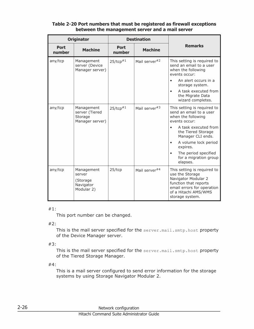
Table 2-20 Port numbers that must be registered as firewall exceptionsbetween the management server and a mail server
Originator DestinationRemarksPort
number Machine Portnumber Machine
any/tcp Managementserver (DeviceManager server)
25/tcp#1 Mail server#2 This setting is required tosend an email to a userwhen the followingevents occur:• An alert occurs in a
storage system.• A task executed from
the Migrate Datawizard completes.
any/tcp Managementserver (TieredStorageManager server)
25/tcp#1 Mail server#3 This setting is required tosend an email to a userwhen the followingevents occur:• A task executed from
the Tiered StorageManager CLI ends.
• A volume lock periodexpires.
• The period specifiedfor a migration groupelapses.
any/tcp Managementserver(StorageNavigatorModular 2)
25/tcp Mail server#4 This setting is required touse the StorageNavigator Modular 2function that reportsemail errors for operationof a Hitachi AMS/WMSstorage system.
#1:This port number can be changed.
#2:This is the mail server specified for the server.mail.smtp.host propertyof the Device Manager server.
#3:This is the mail server specified for the server.mail.smtp.host propertyof the Tiered Storage Manager.
#4:This is a mail server configured to send error information for the storagesystems by using Storage Navigator Modular 2.
2-26 Network configurationHitachi Command Suite Administrator Guide

Table 2-21 Port numbers that must be registered as firewall exceptionsbetween the management server and an external authentication server
Originator DestinationRemarksPort
number Machine Portnumber Machine
any/tcp Managementserver
88/tcp# Kerberos server -
any/tcp Managementserver
88/udp# Kerberos server -
any/tcp Managementserver
359/tcp# LDAP directoryserver
-
any/tcp Managementserver
1812/udp# RADIUS server -
Legend:-: Not applicable
#:This port number is generally used. However, a different port numbermight be used for an external authentication server.
Table 2-22 Port numbers that must be registered as firewall exceptionswhen you manage copy pairs by using the pair management server
Originator DestinationRemarksPort
number Machine Portnumber Machine
any/udp • Normal host• Virtual
machine
31001/udp • VSP G1000• Virtual
StoragePlatform
• HUS VM
-
Legend:-: Not applicable
Related topics
• Registering firewall exceptions for Device Manager and Tiered StorageManager in Windows on page 2-28
• Registering firewall exceptions for Device Manager and Tiered StorageManager in Red Hat Enterprise Linux on page 2-29
• Registering firewall exceptions for Device Manager and Tiered StorageManager in SUSE Linux Enterprise Server on page 2-29
Network configuration 2-27Hitachi Command Suite Administrator Guide

Registering firewall exceptions for Device Manager and TieredStorage Manager in Windows
To add the components that make up Hitachi Command Suite to the firewallexceptions list, execute the hcmds64fwcancel and netsh commands.
To add the components to the firewall exceptions list:
1. Execute the following command to add the Hitachi Command SuiteCommon Web Service to the exceptions list:installation-folder-for-Hitachi-Command-Suite\Base64\bin\hcmds64fwcancel
2. Execute the following command to add the other components that makeup Hitachi Command Suite to the exceptions list.netsh advfirewall firewall add rule name="name-added-to-exceptions-list" dir=in action=allow program="path"description="path" enable=yes
3. To enable the settings, restart the Hitachi Command Suite productservices.
Table 2-23 Names added to the exceptions list and paths specified withthe netsh command
ComponentName added tothe exceptions
listPath
Device Managerserver
Device Manager installation-folder-for-Hitachi-Command-Suite\DeviceManager\HiCommandServer\HiCommandServer.exe
Tiered StorageManager server
Tiered StorageManager(htsmService)
installation-folder-for-Hitachi-Command-Suite\TieredStorageManager\bin\htsmService.exe
JDK Device Manager- HBase64(java)
installation-folder-for-Hitachi-Command-Suite\Base64\uCPSB\hjdk\jdk\jre\bin\java.exe#
Tiered StorageManager -HBase64(java)
installation-folder-for-Hitachi-Command-Suite\Base64\uCPSB\hjdk\jdk\bin\java.exe#
#:If you want to use a JDK other than the one that comes with HitachiCommand Suite, specify the absolute path to the java.exe in theinstallation folder of the JDK you will use.
Related topics
• Port numbers that must be registered as firewall exceptions for DeviceManager and Tiered Storage Manager on page 2-15
• Starting the Hitachi Command Suite services on page 8-4
2-28 Network configurationHitachi Command Suite Administrator Guide

• Stopping the Hitachi Command Suite services on page 8-5
Registering firewall exceptions for Device Manager and TieredStorage Manager in Red Hat Enterprise Linux
To add the port numbers used by Hitachi Command Suite to the firewallexceptions list, use the text mode setup utility.
To add the port numbers to the firewall exceptions list:
1. In a terminal window, execute the setup command.The Choose a Tool window of the text mode setup utility is displayed.
2. Select Firewall configuration, use the Tab key to move to the RunTool button, and then press Enter.The Firewall Configuration window is displayed.
3. Set Security Level to Enabled by pressing the space key to selectEnabled, use the Tab key to move to the Customize button, and thenpress Enter.The Firewall Configuration - Customize window is displayed.
4. In Other ports specify the port to be registered as an exception, use theTab key to move to the OK button, and then press Enter.Example: Other ports 162:udp 2001:tcp 22015:tcp
Note: If a port is already specified, use a space to separate it from thenewly added entry.
5. After returning to the Firewall Configuration window, check that SecurityLevel is Enabled, use the Tab key to move to the OK button, and thenpress Enter.
Related topics
• Port numbers that must be registered as firewall exceptions for DeviceManager and Tiered Storage Manager on page 2-15
Registering firewall exceptions for Device Manager and TieredStorage Manager in SUSE Linux Enterprise Server
To add the port numbers used by Hitachi Command Suite to the firewallexceptions list, edit the SuSEfirewall2 file.
To add the port numbers to the firewall exceptions list:
1. Edit the /etc/sysconfig/SuSEfirewall2 file to specify the port to beregistered as an exception.Specify the port numbers to be registered as exceptions, in the followingformat:
¢ FW_SERVICES_EXT_TCP="TCP-port-number"¢ FW_SERVICES_EXT_UDP="UDP-port-number"
Network configuration 2-29Hitachi Command Suite Administrator Guide

In the following example, only 2001, 22015, 22016, 22017, 22018, 161,and 162 are registered as exceptions:
FW_SERVICES_EXT_TCP="2001 22015:22018"FW_SERVICES_EXT_UDP="161 162"
2. Execute /sbin/SuSEfirewall2.
Related topics
• Port numbers that must be registered as firewall exceptions for DeviceManager and Tiered Storage Manager on page 2-15
Registering firewall exceptions for Host Data Collector(Windows)
If the Windows firewall was enabled or the port used by Host Data Collectorwas changed immediately after Host Data Collector operation started, youneed to manually register firewall exceptions.
Registering an exception for the Host Data Collector service (fornon-SSL communication)
Use the firewall_setup command to register a firewall exception for non-SSL communication ports used by the Host Data Collector service.
A firewall exception is registered for the ports set for the following propertiesin the hdcbase.properties. The exception name Host Data CollectorBase is assigned to these ports.
• hdc.common.rmi.registryPort property (Default value: 22098/tcp)• hdc.common.rmi.serverPort property (Default value: 22099/tcp)• hdc.common.http.serverPort property (Default value: 22100/tcp)
Operations to complete in advance
Log in with administrator permissions.
Command format
firewall_setup.bat {add|del}
Location of the command
installation-folder-for-Host-Data-Collector\HDC\Base\bin
Options
add
2-30 Network configurationHitachi Command Suite Administrator Guide

Adds firewall exceptions.
delRemoves firewall exceptions.
Related topics
• Registering an exception for the Host Data Collector service (for SSLcommunication) on page 2-31
• hdc.common.rmi.registryPort on page C-3• hdc.common.rmi.serverPort on page C-4• hdc.common.http.serverPort on page C-4
Registering an exception for the Host Data Collector service (for SSLcommunication)
Use the netsh command to register a firewall exception for SSLcommunication ports used by the Host Data Collector service.
Operations to complete in advance
Log in with administrator permissions.
Information to collect in advance
• Port number set for the hdc.common.rmi.ssl.registryPort property(Default value: 22104/tcp)
• Port number set for the hdc.common.rmi.ssl.serverPort property(Default value: 22105/tcp)
• Port number set for the hdc.common.https.serverPort property (Defaultvalue: 22106/tcp)
To register a firewall exception for the Host Data Collector service:
1. Execute the following command for each port.netsh advfirewall firewall add rule name="Host Data CollectorBase" dir=in action=allow localport=port-number protocol=TCP
2. Restart the Host Data Collector service to enable the settings.
Tip: To check the registered information, execute the following commands:netsh advfirewall firewall show rule name=all
Related topics
• Starting the Host Data Collector service on page 8-9• Stopping the Host Data Collector service on page 8-9• Registering an exception for the Host Data Collector service (for non-SSL
communication) on page 2-30
Network configuration 2-31Hitachi Command Suite Administrator Guide

• hdc.common.rmi.ssl.registryPort on page C-5• hdc.common.rmi.ssl.serverPort on page C-5• hdc.common.https.serverPort on page C-6
Network settings with multiple IP addressesThis section describes communication settings for multiple networkconfigurations.
Network settings for using a management server as a bridge To use the management server as a network bridge by installing multiplenetwork interface cards (NICs) on the server, set up the networks so that themanagement server, management client, and storage systems can mutuallycommunicate.
The sections where settings must be specified are explained by using theconfiguration example shown below.
Figure 2-1 Example of a configuration in which the management server isused as a bridge between networks
Set up the routers, the management client, and the management server sothat the devices can mutually communicate as indicated by the arrows in theabove figure.
• Enterprise-class storage system and HUS VM, and the management client
2-32 Network configurationHitachi Command Suite Administrator Guide

• Enterprise-class storage system and HUS VM, and the managementserver
• Midrange storage systems and the management server
You do not have to set up communication between a management client anda member of midrange storage systems because Storage Navigator Modular 2or Storage Navigator Modular manages this communication.
Caution: An IP address on the network to which the management client isconnected (10.0.0.100 in Figure 2-1 Example of a configuration in which themanagement server is used as a bridge between networks on page 2-32)must be specified for the Hitachi Command Suite product settings below. Donot specify a host name.
• The setting for the computer on which the Device Manager Web serverfunction is running (the server.http.host property)
• The URL setting for the Storage Navigator Modular 2 instance launchedfrom Device Manager (the launchapp.snm2.url property)
Related topics
• Changing Device Manager server properties on page A-4• server.http.host on page A-5• launchapp.snm2.url on page A-36
Specifying settings if the Host Data Collector machine has multipleIP addresses
If the Host Data Collector machine has multiple IP addresses, you mustspecify the IP address to be used for communication with the Device Managerserver for the hdc.service.rmi.registryIPAddress property in thehdcbase.properties file for Host Data Collector.
Related topics
• hdc.service.rmi.registryIPAddress on page C-6
Device Manager settings in IPv6 environmentsDevice Manager supports IPv6-based communication. To use Device Managerin an IPv6 environment, you need to change the Device Manager settingsaccording to the environment's requirements.
To use Device Manager in an IPv6 environment, make sure that the DeviceManager settings meet the following requirements:
• Set up the OS so that both IPv6 and IPv4 can be used because, even ifIPv6 is being used, IPv4 is also required for processing in the product.
Network configuration 2-33Hitachi Command Suite Administrator Guide

• You can only use global addresses as IPv6 addresses. Global-unique localaddresses (site-local addresses), and link-local addresses cannot be used.
• When specifying the IP address or host name of the Device Managerserver, we recommend that you use the host name.
• When operating a Hitachi AMS/WMS storage system from ElementManager, be sure to specify a host name (not an IP address) for theStorage Navigator Modular 2 URL.
Related topics
• Settings required for linking with Storage Navigator Modular 2 on page5-2
Settings for migrating Device Manager to an IPv6 environmentIf Device Manager is used in an IPv4 environment and you intend to use it inan IPv6 environment, edit the user_httpsd.conf file.
Note: If Device Manager is installed as a new installation in an IPv6environment, the procedure described below is not necessary because theinstaller automatically changes the settings.However, after the installation, if you link the system with Hitachi FileServices Manager or Storage Navigator Modular 2, make sure that IPv6communication is enabled in the following file:
• In Windows:installation-folder-for-Hitachi-File-Services-Manager-or-Storage-Navigator-Modular-2\Base\jdk\jre\lib\security\jssecacerts
• In Linux:installation-directory-for-Hitachi-File-Services-Manager-or-Storage-Navigator-Modular-2/Base/jdk/jre/lib/security/jssecacerts
To migrate Device Manager to an IPv6 environment:
1. Stop the Hitachi Command Suite product services.2. Open the user_httpsd.conf file.
The user_httpsd.conf file is stored in the following locations:
¢ In Windows:installation-folder-for-Hitachi-Command-Suite\Base64\uCPSB\httpsd\conf\user_httpsd.conf
¢ In Linux:installation-directory-for-Hitachi-Command-Suite/Base64/uCPSB/httpsd/conf/user_httpsd.conf
Note: Do not edit the httpsd.conf file that is stored in the same locationas the user_httpsd.conf file.
2-34 Network configurationHitachi Command Suite Administrator Guide

However, if the system is linked with Hitachi File Services Manager orStorage Navigator Modular 2, edit the httpsd.conf file that is stored inthe following location.In Windows:installation-folder-for-Hitachi-File-Services-Manager-or-Storage-Navigator-Modular-2\Base\jdk\jre\lib\security\jssecacertsIn Linux:installation-directory-for-Hitachi-File-Services-Manager-or-Storage-Navigator-Modular-2/Base/jdk/jre/lib/security/jssecacertsUse the same method to edit the file as you used for theuser_httpsd.conf file. However, for the port number, specify the portnumber for HBase Storage Mgmt Web Service (the default port for non-SSL communication is 23015, and the default port for SSL communicationis 23016).
3. Delete the heading hash mark (#) from the #Listen [::]:port-numberline to enable IPv6-based communication.
Caution:
• If you use non-SSL communication, you do not need to delete thehash mark (#) from the Listen line under SSLDisable.
• By default, all IPv6 addresses are set to allow communication.• Specify the same port number as specified in the Listen line for IPv4.• Do not delete or edit the Listen line. If you do so, communication via
IPv4 will no longer be possible in the environment.4. Start the Hitachi Command Suite product services.
Related topics
• Editing the user_httpsd.conf file on page 4-36• Starting the Hitachi Command Suite services on page 8-4• Stopping the Hitachi Command Suite services on page 8-5
Settings for linking with storage systems that support IPv6To operate Universal Storage Platform V/VM storage systems that aremanaged using IPv6 addresses from Element Manager, edit theserver.properties file on the Device Manager server.
To link with storage systems that support IPv6:
1. On the Device Manager server, open the server.properties file, and seteither of the following items for the server.http.host property:
¢ The IPv6 address of the computer on which the Device Managerserver is installed
Network configuration 2-35Hitachi Command Suite Administrator Guide

¢ The host name of the computer on which the Device Manager serveris installedThe host name must be resolvable to the IPv6 address.
Caution: If Universal Storage Platform V/VM storage system or HitachiUSP storage system that is managed via an IPv4 address is also set up asa Device Manager management-target, IPv4 addresses must also be setfor any NICs that have IPv6 addresses specified for theserver.http.host property.
Related topics
• Changing Device Manager server properties on page A-4• server.http.host on page A-5
Changing the IP address or host name of the managementserver
If you change the IP address or host name of the management serverbecause of changes to the network configuration, you also need to changethe settings for Hitachi Command Suite products.
Changing the host name of the management serverTo apply the changed host name to the Hitachi Command Suite products, editthe /etc/hosts file (in Linux) , user_httpsd.conf file, and cluster.conffile (for cluster configurations), and then restart the computer.
Information to collect in advance
• Changed host name of the management serverThe host name must be no more than 128 bytes. For Hitachi CommandSuite products, the host name is case sensitive.
Tip: If you change the host name of the management server in advance,keep a note of the new host name that is displayed by the hostnamecommand. In Windows, you can also use the ipconfig /ALL command todisplay the host name.
To change the host name of the management server:
1. Stop the Hitachi Command Suite product services.2. If SSL/TLS is used for communication between the following components,
re-create a server certificate of the management server by using the newhost name:
¢ Between a management server and a management client (GUI)¢ Between a management server and a management client (Device
Manager CLI)
2-36 Network configurationHitachi Command Suite Administrator Guide

¢ Between a Device Manager server and Replication Manager server¢ Between a Tuning Manager server and a Device Manager server¢ Between a management server and a CIM client
3. If the OS is Linux, edit the /etc/hosts file.Change the host name of the management server to the new host name.For Linux, write the new host name into the line above the localhostline.
4. Edit the user_httpsd.conf file.Change the value for the ServerName directive to the new host name.
¢ In Windows:installation-folder-for-Hitachi-Command-Suite\Base64\uCPSB\httpsd\conf\user_httpsd.conf
¢ In Linux:installation-directory-for-Hitachi-Command-Suite/Base64/uCPSB/httpsd/conf/user_httpsd.conf
If TLS/SSL is used for communication between the management serverand management clients, you also need to change the following settings:
¢ If a host name has been specified for the <VirtualHost> tag, changethe host name to an asterisk (*).
¢ Change the value for the ServerName directive in the <VirtualHost>tag to the new host name.
Note: Do not edit the httpsd.conf, hsso_httpsd.conf, anduser_hsso_httpsd.conf files.
5. Edit the cluster.conf file (only for a cluster configuration).Change the corresponding logical host name, executing node's hostname, and standby node's host name to the new host names.installation-folder-for-Hitachi-Command-Suite\Base64\conf\cluster.conf
6. Change the host name for the management server, and then restart thecomputer.If you have changed the host name for the management server beforechanging the Common Component settings files, just restart thecomputer.
7. Make sure that the Hitachi Command Suite product services are runningproperly.
8. If the host name is used in the URLs of Hitachi Command Suite products,change the settings of all Hitachi Command Suite products that areinstalled on the management server.
9. Depending on the operating environment, review the Hitachi CommandSuite product settings.
10. Back up the database.If you change the host name, the data that you backed up can no longerbe used.
Network configuration 2-37Hitachi Command Suite Administrator Guide

Related topics
• Required operations after changing the IP address or host name of themanagement server on page 2-39
• Changing the URL for accessing Hitachi Command Suite products(hcmds64chgurl command) on page 2-41
• Editing the user_httpsd.conf file on page 4-36• Stopping the Hitachi Command Suite services on page 8-5• Checking the operating status of the Hitachi Command Suite services on
page 8-7• Backing up a database in non-cluster configuration on page 9-3• Backing up a database in a cluster configuration on page 9-4
Changing the IP address of the management serverTo apply the changed IP address to the Hitachi Command Suite products, editthe user_httpsd.conf file, and then restart the computer.
Information to collect in advance
Changed IP address of the management server.
Caution: Do not change the settings in the cluster configuration file (thecluster.conf file).
To change the IP address of the management server:
1. Stop the Hitachi Command Suite product services.2. Edit the user_httpsd.conf file.
If the old IP address is specified for the ServerName directive, change theIP address to the host name or the new IP address.
¢ In Windows:installation-folder-for-Hitachi-Command-Suite\Base64\uCPSB\httpsd\conf\user_httpsd.conf
¢ In Linux:installation-directory-for-Hitachi-Command-Suite/Base64/uCPSB/httpsd/conf/user_httpsd.conf
Note:
• Do not edit the httpsd.conf file.• We recommend that you specify the host name in the
user_httpsd.conf file.
3. Change the IP address of the management server, and then restart thecomputer.If the IP address of the management server has already been changedbefore you change the Common Component settings files, just restart thecomputer.
2-38 Network configurationHitachi Command Suite Administrator Guide

4. Make sure that the Hitachi Command Suite product services are runningproperly.
5. If the IP address is used in the URLs of Hitachi Command Suite products,change the settings of all Hitachi Command Suite products that areinstalled on the management server.
6. Depending on the operating environment, review the Hitachi CommandSuite product settings.
7. Back up the database.If you change the IP address, the data that you backed up can no longerbe used.
Related topics
• Required operations after changing the IP address or host name of themanagement server on page 2-39
• Changing the URL for accessing Hitachi Command Suite products(hcmds64chgurl command) on page 2-41
• Editing the user_httpsd.conf file on page 4-36• Stopping the Hitachi Command Suite services on page 8-5• Checking the operating status of the Hitachi Command Suite services on
page 8-7• Backing up a database in non-cluster configuration on page 9-3• Backing up a database in a cluster configuration on page 9-4
Required operations after changing the IP address or host name ofthe management server
If you change the IP address or host name of the management server, youmight have to review the settings for Device Manager, Tiered StorageManager, and Replication Manager depending on the operating environment.
• When the old host name or IP address is specified for theserver.http.host property:You need to replace the old host name or IP address with the new hostname or IP address, and then restart the services of Hitachi CommandSuite products.
• When the Device Manager agent is used:You need to execute the hdvmagt_setting command to change thesettings for the Device Manager server information.
• When the Replication Manager is used:If you change the IP address or the host name registered as theinformation source, re-register the information source. .
• When Element Manager is used to operate a Hitachi AMS/WMS storagesystem:You must use launchapptool to modify the URL settings.
• When a RADIUS server is used to authenticate accounts:
Network configuration 2-39Hitachi Command Suite Administrator Guide

Check the settings in the exauth.properties file.• When the Device Manager server and the Tuning Manager server are
remotely connected:If all the following conditions are satisfied, change the registration ofrepository location:
¢ The IP address of the computer on which the Device Manager serveris installed was changed.
¢ The IP address of the computer on which the Device Manager serveris installed is set in the hsso.conf file of the computer on which theTuning Manager server is installed.
• If acquiring performance information from Tuning ManagerRevise the ownHost parameter setting in the config.xml file and theconfigforclient.xml file.
• If receiving SNMP traps from file serversYou must change the host name or IP address of the notificationdestination for SNMP traps (the SNMP manager) by using Hitachi FileServices Manager.
• If user accounts are authenticated in Hitachi Command Suite whenlogging in to CCI or the SVPIn Device Manager GUI, from the Edit Storage Systems window, re-setuser account authentication.
If there are other script files or batch files in which an IP address or a hostname is specified, review the settings.
Related topics
• Registering an external authentication server and an externalauthorization server on page 3-17
• Settings for using Element Manager on page 5-3• Setting up the config.xml and configforclient.xml files on page 5-19• Starting the Hitachi Command Suite services on page 8-4• Stopping the Hitachi Command Suite services on page 8-5• Setting the Device Manager server's information, HiScan command's
execution period, and CCI's information (hdvmagt_setting command) onpage 10-20
• Changing Device Manager server properties on page A-4• server.http.host on page A-5• How to register the Replication Manager information source: Replication
Manager User Guide• How to change the registration of the repository location: Tuning Manager
Server Administration Guide• How to change the SNMP trap notification destination for the file server:
The file server manuals.
2-40 Network configurationHitachi Command Suite Administrator Guide

• About settings required for products other than Device Manager, TieredStorage Manager, and Replication Manager: The manuals for HitachiCommand Suite products.
Changing the URL for accessing Hitachi Command Suiteproducts (hcmds64chgurl command)
After starting Hitachi Command Suite operation, if a product URL is changeddue to any of the following configuration changes, you must use thehcmds64chgurl command to change the URL registered in the GUI for eachproduct:
• Changing a port used by HBase 64 Storage Mgmt Web Service• Changing the host name or IP address of the management server• Changing the settings for enabling or disabling SSL communication• Migrating to a cluster environment
To change Hitachi Command Suite product URLs:
1. Execute the hcmds64chgurl command.
In Windows:installation-folder-for-Hitachi-Command-Suite\Base64\bin\hcmds64chgurl {/print | /list | /change old-URL new-URL| /change new-URL /type Hitachi-Command-Suite-product-name}
In Linux:installation-directory-for-Hitachi-Command-Suite/Base64/bin/hcmds64chgurl {-print | -list | -change old-URLnew-URL | -change new-URL -type Hitachi-Command-Suite-product-name}
¢ printSpecify this option to display a list of URLs and programs that arecurrently registered.
¢ listSpecify this option to display the same information as the printoption in a different format.
¢ changeSpecify this option to change a currently registered URL.
¢ typeIf you want to change the URL for a specific Hitachi Command Suiteproduct only, use this option to specify the name of that product. Tochange only the Device Manager URL, specify DeviceManager. Tochange only the Tiered Storage Manager URL, specifyTieredStorageManager. To change only the Replication Manager URL,specify ReplicationManager. For details on the names of otherHitachi Command Suite products, see the documentation for eachproduct.
Network configuration 2-41Hitachi Command Suite Administrator Guide

2. In Windows, change the URL in the shortcut file.
In Windows Server 2008 R2:Select Start, All Programs, Hitachi Command Suite, and thenright-click Login - HCS. In Properties, change the URL on the WebDocument tab.
In Windows Server 2012 or Windows Server 2012 R2:From the Start window, display the list of applications, then underHitachi Command Suite, right-click Login - HCS. In Properties,change the URL on the Web Document tab.
The URL format is as follows:protocol://IP-address-of-the-management-server:port-number/DeviceManager/¢ protocol
Specify http for non-SSL communication, and https for SSLcommunication.
¢ IP-address-of-the-management-serverSpecify the IP address or host name of the management server.
¢ port-numberSpecify the port number that is set in the Listen line in theuser_httpsd.conf file.For non-SSL communication, specify the port number for non-SSLcommunication (default: 22015). For SSL communication, specify theport number for SSL communication (default: 22016).The user_httpsd.conf file is stored in the following location:installation-folder-for-Hitachi-Command-Suite\Base64\uCPSB\httpsd\conf\user_httpsd.conf
Caution:
• The specified URL must be a complete URL that contains protocols and aport number. You cannot use an IPv6 address. You must use a host nameto specify the URL in an IPv6 environment, as shown in the followingexample:http://hostname:22015
• When changing the URL during migration to a cluster environment, usethe following format to specify new-URL:http://logical-host-name:port-number
Related topics
• Changing ports used by Common Component on page 2-10• Changing the host name of the management server on page 2-36• Changing the IP address of the management server on page 2-38• Operation workflow for secure communication between a management
server and a management client (GUI) on page 4-9
2-42 Network configurationHitachi Command Suite Administrator Guide

• How to migrate from a non-cluster configuration to a clusterconfiguration: Hitachi Command Suite Installation and ConfigurationGuide
Network configuration 2-43Hitachi Command Suite Administrator Guide

2-44 Network configurationHitachi Command Suite Administrator Guide

3User account management
This chapter describes the settings required for managing user accounts ofHitachi Command Suite products.
□ About password policies
□ About account locking
□ User management on an external authentication server
User account management 3-1Hitachi Command Suite Administrator Guide

About password policiesA password policy is a set of conditions related to the number of characters orcombinations of character types that can be used in passwords for useraccounts.
By setting a password policy, you can prevent users from setting easilyguessed passwords, and reduce the risk of unauthorized access from thirdparties.
You can specify the following conditions in a password policy:
• Minimum password length• Minimum number of uppercase letters used in passwords• Minimum number of lowercase letters used in passwords• Minimum number of numerals used in passwords• Minimum number of symbols used in passwords• Ability to set passwords that are the same as the user ID
If you are using a management server to manage user accounts, werecommend that you set these conditions to increase password complexity.
Setting password policiesPassword policies for Hitachi Command Suite products are set in thesecurity.conf file.
To set a password policy:
1. Edit the security.conf file.The security.conf file is stored in the following locations:
¢ In Windows:installation-folder-for-Hitachi-Command-Suite\Base64\conf\sec\security.conf
¢ In Linux:installation-directory-for-Hitachi-Command-Suite/Base64/conf/sec/security.conf
The following table shows the password policies that can be set in thesecurity.conf file.
Table 3-1 Password policies that can be set in the security.conf file
Item Description
password.min.length Specifies the minimum number of characters thepassword must contain. Specify a value from 1 to256.Default: 4
password.min.uppercase Specifies the minimum number of uppercaseletters the password must contain. Specify a value
3-2 User account managementHitachi Command Suite Administrator Guide

Item Description
from 0 to 256. If you specify 0, no restrictionapplies.Default: 0
password.min.lowercase Specifies the minimum number of lowercaseletters the password must contain. Specify a valuefrom 0 to 256. If you specify 0, no restrictionapplies.Default: 0
password.min.numeric Specifies the minimum number of numericcharacters the password must contain. Specify avalue from 0 to 256. If you specify 0, norestriction applies.Default: 0
password.min.symbol Specifies the minimum number of symbols thepassword must contain. Specify a value from 0 to256. If you specify 0, no restriction applies.Default: 0
password.check.userID Specifies whether the password can be the sameas the user ID. If true is specified, passwordscannot be the same as the corresponding user ID.If false is specified, passwords can be the sameas the corresponding user ID.Default: false
When you change the setting values in the security.conf file, the newpassword policy takes effect immediately.
Caution:
• In all Hitachi Command Suite products, set password policies apply onlyto user accounts that are added and passwords that are changed after thepolicy was set. New password policies do not apply to existing useraccounts, so users of such accounts can log in to the system even if theirpasswords do not satisfy the set conditions.
• You can also set password policies from the GUI. However, if the systemis in a cluster configuration, the settings from the GUI are applied only tothe executing node. To apply the settings to the standby node, switch thenodes, and then specify the same settings.
• If an external authentication server is used to authenticate users,passwords are checked by using a combination of character typesspecified on the external authentication server. However, if you register apassword for a Hitachi Command Suite product user, you need to usecharacter types specified in the Hitachi Command Suite products.
About account lockingAccount locking is the locking (temporary disabling) of a user account.
User account management 3-3Hitachi Command Suite Administrator Guide

By enabling account locking, you can reduce the risk of unauthorized accessfrom third parties. If you are managing user accounts by using amanagement server, we recommend that you enable account locking.
In Hitachi Command Suite products, you can automatically lock user accountsthat fail to log in to the GUI many times in a row.
To enable account locking, you need to set the account locking policy (thenumber of consecutive, unsuccessful login attempts before accounts arelocked).
Tip: As a way to lock an account, you can change the lock status of a useraccount from the GUI.Note that only users with the Admin (user management) permission canchange the lock status.
Caution:
• Account locking cannot be performed on System accounts when initiallyinstalling Hitachi Command Suite products. System accounts are set withAdmin permissions for all Hitachi Command Suite products. If you want toset account locking for System accounts to improve security, you need tochange the settings.
• If an external authentication server is used to authenticate users, thesettings on the external authentication server are used to controlautomatic locking.
About account locking policiesAn account locking policy is the number of consecutive, unsuccessful loginattempts before automatically locking (temporarily disabling) user accountsthat fail to log in to the GUI many times in a row.
When you set an account locking policy, it is immediately applied to allHitachi Command Suite products that use Single Sign-On functionality. Forexample, if you set the number of consecutive failed login attempts to 3 anda user fails to log in to Device Manager once, Tiered Storage Manager once,and then Replication Manager once, the user account is automatically locked.
Setting account locking policiesYou can set an account locking policy for Hitachi Command Suite products inthe security.conf file.
To set an account locking policy:
1. Edit the security.conf file.The security.conf file is stored in the following locations:
¢ In Windows:installation-folder-for-Hitachi-Command-Suite\Base64\conf\sec\security.conf
¢ In Linux:
3-4 User account managementHitachi Command Suite Administrator Guide

installation-directory-for-Hitachi-Command-Suite/Base64/conf/sec/security.conf
The following table shows the account locking policies that can be set inthe security.conf file.
Table 3-2 Account locking policies that can be set in the security.conffile
Item Description
account.lock.num Specify the number of consecutive failed login attemptsrequired to trigger automatic account locking. Specify avalue from 0 to 10.If a user makes the specified number of unsuccessfullogin attempts, his or her user account will be locked.If you specify 0, any number of unsuccessful loginattempts is allowed.Default: 0
If you change the setting values in the security.conf file, the new accountlocking policy takes effect immediately.
Caution:
• If you change the number of consecutive failed login attempts, the newvalue takes effect from the first failed login after the change. If a user iscurrently logged in and you attempt to login using his or her account, butyou fail the specified number of times, his or her user account will belocked. However, the user can continue to perform operations while stilllogged in.
• You can also set an account locking policy from the GUI. However, if thesystem is in a cluster configuration, the settings from the GUI are appliedonly to the executing node. To apply the settings to the standby node,switch the nodes, and then specify the same settings.
Settings for automatically locking the System accountTo apply account locking to System accounts, change the settings in theuser.conf file.
To apply account locking to System accounts:
1. Stop the Hitachi Command Suite product services.2. Open the user.conf file.
The user.conf file is stored in the following locations:
¢ In Windows:installation-folder-for-Hitachi-Command-Suite\Base64\conf\user.conf
¢ In Linux:
User account management 3-5Hitachi Command Suite Administrator Guide

installation-directory-for-Hitachi-Command-Suite/Base64/conf/user.conf
If the user.conf file does not exist, create it.3. Use the following format to specify the account.lock.system property:
account.lock.system=true
4. Start the Hitachi Command Suite product services.
Account locking is applied to System accounts for all Hitachi Command Suiteproducts.
Related topics
• Starting the Hitachi Command Suite services on page 8-4• Stopping the Hitachi Command Suite services on page 8-5
Unlocking accountsLocked user accounts can be unlocked by using the hcmds64unlockaccountcommand.
Operations to complete in advance
Log in as a user with Administrator permissions (for Windows) or as a rootuser (for Linux).
Information to collect in advance
• Confirmation that the locked user account has User Management AdminpermissionsIf a user account does not have User Management Admin permissions,another user whose account has User Management Admin permissionsmust unlock the account.
• The user ID and password of the locked user account
To unlock a locked account:
1. Execute the hcmds64unlockaccount command to unlock the account.
In Windows:installation-folder-for-Hitachi-Command-Suite\Base64\bin\hcmds64unlockaccount [/user user-ID /pass password]
In Linux:installation-directory-for-Hitachi-Command-Suite/Base64/bin/hcmds64unlockaccount [-user user-ID -passpassword]
If the command is executed without specifying the user option or thepass option, you will be prompted to enter a user ID and password.
3-6 User account managementHitachi Command Suite Administrator Guide

Caution: If any symbols are used in the user ID or password, you needto escape these symbols on the command line.
• In Windows:If the user ID or password ends with a backslash (\), use anotherbackslash (\) to escape that backslash (\).Also, if the user ID or password includes an ampersand (&), verticalbar (|), or caret (^), enclose each character with a double quotationmark ("), or use a caret (^) to escape the symbols.
• In Linux:Use a backslash (\) to escape each character.
User management on an external authentication serverHitachi Command Suite products not only allow you to register user accountsand use them in Common Component (internal authentication), but also allowyou to use the user accounts that are under the integrated management ofan external authentication server or an external authorization server.
By using user accounts managed by an external authentication server or anexternal authorization server, you do not need to manage the operations ofHitachi Command Suite products, thereby reducing your workload.
About linking to an external authentication server Hitachi Command Suite products allow you to log in to the GUI or execute CLIcommands by using the user accounts registered on an externalauthentication server.
When an external authentication server is linked to, you do not need toperform login password management and account control for HitachiCommand Suite products.
Hitachi Command Suite products can be linked to the following externalauthentication servers:
• LDAP directory server• RADIUS server• Kerberos server
About linking to an external authorization serverIn addition to an external authentication server, if you also use an externalauthorization server to perform user authentication, access permissions forthe management server ( a Hitachi Command Suite product) can becontrolled on the external authorization server.
When an external authorization server is also linked to, you do not need tomanage accounts and set permissions for individual users because Hitachi
User account management 3-7Hitachi Command Suite Administrator Guide

Command Suite products manage users by using the authorization groups onthe external authorization server.
Hitachi Command Suite products can be linked to an LDAP directory server(Active Directory).
Operating workflow for user authentication on an externalauthentication server
To use the GUI or CLI of Hitachi Command Suite products by using the useraccounts managed by an external authentication server, you need to set upan environment for the external authentication server, management server,and management clients.
Operating workflow for user authentication on an LDAP directory server
To perform user authentication on an LDAP directory server, you need toregister the external authentication server and the accounts to beauthenticated on the management server for Hitachi Command Suiteproducts.
3-8 User account managementHitachi Command Suite Administrator Guide

Figure 3-1 Operating workflow for user authentication on an LDAPdirectory server
Note:
User account management 3-9Hitachi Command Suite Administrator Guide

• When a Hitachi Command Suite product is in operation, to switch to thesystem configuration linked to an external authorization server, deleteany user ID that has the same name as the ID registered in CommonComponent, or change the user name. If the same user name isregistered, when the user logs in to the Hitachi Command Suite product,the user is authenticated in Common Component (internalauthentication).
• In Replication Manager, All Resources is automatically assigned as aresource group to users who belong to authorization groups. If the Modifypermission is set for authorization groups, the Storage Administrator userrole is assigned to the users that belong to the authorization groups. Theuser role cannot be changed.
• Users who belong to nested groups of a registered authorization groupcan now also use Hitachi Command Suite products via the roles(permissions) set for the authorization group.
• To use StartTLS to communicate between the LDAP directory server andthe management server, you need to set up an environment specificallyfor this purpose to ensure secure communications.
Related topics
• Account conditions for Hitachi Command Suite products on page 3-14• About the data structures of user entries on page 3-15• Registering an external authentication server and an external
authorization server on page 3-17• About a LDAP search user account on page 3-41• Checking connections to an external authentication server and an external
authorization server on page 3-47• Secure communication for Device Manager and Tiered Storage Manager
on page 4-5• Operations on a management client: Hitachi Command Suite User Guide
or Replication Manager User Guide
Operating workflow for user authentication on a RADIUS server
To perform user authentication on a RADIUS server, you need to register theexternal authentication server and the accounts to be authenticated on themanagement server for Hitachi Command Suite products.
3-10 User account managementHitachi Command Suite Administrator Guide

Figure 3-2 Operating workflow for user authentication on a RADIUS server
User account management 3-11Hitachi Command Suite Administrator Guide

Note:
• When a Hitachi Command Suite product is in operation, to switch to thesystem configuration linked to an external authorization server, deleteany the user ID that has the same name as the ID registered in CommonComponent, or change the user name. If the same user name isregistered, when the user logs in to a Hitachi Command Suite product,the user is authenticated in Common Component (internalauthentication).
• In Replication Manager, All Resources is automatically assigned as aresource group to users who belong to authorization groups. If the Modifypermission is set for authorization groups, the Storage Administrator userrole is assigned to the users that belong to the authorization groups. Theuser role cannot be changed.
• Users who belong to nested groups of a registered authorization groupcan now also use Hitachi Command Suite products via the roles(permissions) set for the authorization group.
• To use StartTLS to communicate between the LDAP directory server andthe management server, you need to set up an environment specificallyfor this purpose to ensure secure communications.
Related topics
• Account conditions for Hitachi Command Suite products on page 3-14• About the data structures of user entries on page 3-15• Registering an external authentication server and an external
authorization server on page 3-17• About a LDAP search user account on page 3-41• Registering a shared secret on page 3-46• Checking connections to an external authentication server and an external
authorization server on page 3-47• Secure communication for Device Manager and Tiered Storage Manager
on page 4-5• Operations on a management client: Hitachi Command Suite User Guide
or Replication Manager User Guide
Operation workflow for user authentication on a Kerberos server
To perform user authentication on a Kerberos server, you need to register theexternal authentication server and the accounts to be authenticated on themanagement server for Hitachi Command Suite products.
3-12 User account managementHitachi Command Suite Administrator Guide

Figure 3-3 Operation workflow for user authentication on a Kerberosserver
Note:
User account management 3-13Hitachi Command Suite Administrator Guide

• When a Hitachi Command Suite product is in operation, to switch to thesystem configuration linked to an external authorization server, deleteuser any ID that has the same name with the ID registered in CommonComponent, or change the user name. If the same user name isregistered, when the user logs in to a Hitachi Command Suite product,the user is authenticated in Common Component (internalauthentication).
• In Replication Manager, All Resources is automatically assigned as aresource group to users who belong to authorization groups. If the Modifypermission is set for authorization groups, the Storage Administrator userrole is assigned to the users that belong to the authorization groups. Theuser role cannot be changed.
• Users who belong to nested groups of a registered authorization groupcan now also use Hitachi Command Suite products via the roles(permissions) set for the authorization group.
• To use StartTLS to communicate between the LDAP directory server andthe management server, you need to set up an environment specificallyfor this purpose to ensure secure communications.
Related topics
• Account conditions for Hitachi Command Suite products on page 3-14• About the data structures of user entries on page 3-15• Registering an external authentication server and an external
authorization server on page 3-17• About a LDAP search user account on page 3-41• Checking connections to an external authentication server and an external
authorization server on page 3-47• Secure communication for Device Manager and Tiered Storage Manager
on page 4-5• Operations on a management client: Hitachi Command Suite User Guide
or Replication Manager User Guide
Account conditions for Hitachi Command Suite productsUser accounts (user IDs and passwords) for Hitachi Command Suite productsmust consist of characters that can be used in both the externalauthentication server and Hitachi Command Suite products.
Set user accounts so that they satisfy the following conditions:
• They are within 256 bytes.• They use no characters other than the following:
A to Za to z0 to 9! # $ % & ' ( ) * + - . = @ \ ^ _ |
3-14 User account managementHitachi Command Suite Administrator Guide

In Hitachi Command Suite products, user IDs are not case-sensitive. Thecombination of character types for passwords must follow the settings in theexternal authentication server.
About the data structures of user entriesThere are two data structures of user entries for an LDAP directory server:the hierarchical structure model and the flat model.
When performing user authentication on an LDAP directory server, checkwhich data structure is being used, because information about the LDAPdirectory server registered on the management server and the operations youneed to perform on the management server depend on the data structure.
In addition, when performing user authentication or authorization on an LDAPdirectory server, also check BaseDN, which is the start point for searching forusers. Only user entries that are in the hierarchies below BaseDN are subjectto authentication or authorization.
About the hierarchical structure model
A data structure in which the hierarchies below BaseDN branch off and inwhich user entries are registered in another hierarchy.
If the hierarchical structure model is used, the entries in the hierarchy belowBaseDN are searched for an entry that has the same login ID and userattribute value. The following figure shows an example of the hierarchicalstructure model.
Figure 3-4 Example of the hierarchical structure model
The user entries enclosed by the dotted line can be authenticated. In thisexample, BaseDN is cn=group,dc=example,dc=com, because the target userentries extend across two departments (cn=sales and cn=development).
User account management 3-15Hitachi Command Suite Administrator Guide

About the flat model
A data structure in which there are no branches in the hierarchy belowBaseDN and in which user entries are registered in the hierarchy located justbelow BaseDN.
If the flat model is used, the entries in the hierarchy below BaseDN aresearched for an entry that has the DN that consists of a combination of thelogin ID and BaseDN. If such a value is found, the user is authenticated. Thefollowing figure shows an example of the flat model.
Figure 3-5 Example of the flat model
The user entities enclosed by the dotted line can be authenticated. In thisexample, BaseDN is ou=people,dc=example,dc=com, because all of the userentries are located just below ou=people.
Note, however, that even if the flat model is being used, if either of thefollowing conditions is satisfied, specify the settings by following theexplanation for the hierarchical structure model:
• If a user attribute value other than the RDN attribute value is used as theuser ID of a Hitachi Command Suite product:If a user attribute value other than the RDN attribute value (for example,the Windows logon ID) of a user entry is used as the user ID of a HitachiCommand Suite product, you must use the authentication method for thehierarchical structure model.
• If the RDN attribute value of a user entry includes an invalid characterthat cannot be used in a user ID for a Hitachi Command Suite product:When using the authentication method for the flat model, the RDNattribute value of a user entry functions as the user ID for HitachiCommand Suite products. Therefore, if the RDN attribute value of a userentry includes an invalid character that cannot be used in a user ID of aHitachi Command Suite product, you cannot use the authenticationmethod for the flat model.Example of a valid RDN:uid=John123S
3-16 User account managementHitachi Command Suite Administrator Guide

cn=John_SmithExample of an invalid RDN:uid=John:123S (A colon is used.)cn=John Smith (A space is used between John and Smith.)
About the BaseDN
BaseDN is the start point for searching for users during authentication orauthorization.
Only user entries in the hierarchies below BaseDN are subject toauthentication or authorization. In Hitachi Command Suite products, userentries must contain all of the users to be authenticated or authorized.BaseDN is required when registering information about the LDAP directoryserver on the management server.
Registering an external authentication server and an externalauthorization server
In the exauth.properties file, set the type of the external authenticationserver to be used, the server identification name, and the machineinformation about the external authentication server and externalauthorization server.
Operations to complete in advance
• Log in as a user with Administrator permissions (for Windows) or as aroot user (for Linux).
• Copy the template of the exauth.properties file.
In Windows:installation-folder-for-Hitachi-Command-Suite\Base64\sample\conf\exauth.properties
In Linux:installation-directory-for-Hitachi-Command-Suite/Base64/sample/conf/exauth.properties
• Check the data structure of user entries (for LDAP authentication).(see About the data structures of user entries on page 3-15)
• Set up the environment for the DNS server on the OS of the LDAPdirectory server.#
• Register information about the LDAP directory server to the SRV record ofthe DNS server.#
#: This operation is required to look up the information about the LDAPdirectory server by using the DNS server.
User account management 3-17Hitachi Command Suite Administrator Guide

Information to collect in advance
• Common information:
¢ Type of the external authentication server• For LDAP authentication:
¢ Machine information about the external authentication server and theexternal authorization serverHost name or IP addressPort number
¢ BaseDN¢ Domain name managed by the LDAP directory server (when linking to
an external authorization server)• For RADIUS authentication:
¢ Machine information about the external authentication server and theexternal authorization serverHost name or IP addressPort number
¢ Authentication protocol¢ Host name or IP address of the management server¢ Domain name managed by the LDAP directory server (when linking to
an external authorization server)¢ BaseDN (when linking to an external authorization server)
• For Kerberos authentication:
¢ Machine information about the external authentication server and theexternal authorization serverHost name or IP addressPort name
¢ Realm name¢ Domain name managed by the LDAP directory server (when linking to
an external authorization server)¢ BaseDN (when linking to an external authorization server)
To register an external authentication server and an externalauthorization server:
1. Specify required items in the exauth.properties file being copied.2. Save the exauth.properties file in the following location:
In Windows:installation-folder-for-Hitachi-Command-Suite\Base64\conf\exauth.properties
In Linux:installation-directory-for-Hitachi-Command-Suite/Base64/conf/exauth.properties
3-18 User account managementHitachi Command Suite Administrator Guide

3. If the setting value of the auth.ocsp.enable orauth.ocsp.responderURL property is changed, the Hitachi CommandSuite product services must be restarted.If the setting value of any other property or attribute is changed, thechange takes effect immediately.
Related topics
• Starting the Hitachi Command Suite services on page 8-4• Stopping the Hitachi Command Suite services on page 8-5
Setup items in the exauth.properties file for LDAP authentication
In the exauth.properties file, set the type of the external authenticationserver to be used, the server identification name, and the machineinformation about the external authentication server.
• Common propertiesTable 3-3 Setup items in the exauth.properties file for LDAPauthentication (common items) on page 3-20
• Properties for an external authentication server and an externalauthorization serverSetup items in the exauth.properties file vary depending on whetherinformation about the LDAP directory server being connected to is directlyspecified or looked up by using the DNS server.
¢ When directly specifying information about the LDAP directory server:Table 3-4 Setup items in the exauth.properties file for LDAPauthentication (when directly specifying information about theexternal authentication server) on page 3-20Table 3-5 Setup items in the exauth.properties file for LDAPauthentication (when an external authentication server and StartTLSare used for communication) on page 3-23
¢ When using the DNS server to look up information about the LDAPdirectory server:Table 3-6 Setup items in the exauth.properties file for LDAPauthentication (when using the DNS server to look up informationabout the external authentication server) on page 3-23
Note:
• To use StartTLS for communication between the management server andthe LDAP directory server, you need to directly specify information aboutthe LDAP directory server to connect to in the exauth.properties file.
• If you use the DNS server to look up the LDAP directory server to connectto, it might take longer for users to log in.
User account management 3-19Hitachi Command Suite Administrator Guide

Table 3-3 Setup items in the exauth.properties file for LDAP authentication(common items)
Property Details
auth.server.type Specify an external authentication server type. Specify ldap.
Default value: internal (used when not linking to an externalauthentication server)
auth.server.name Specify the server identification names of LDAP directoryservers. You can specify any name for this property in order toidentify which LDAP directory servers the settings such as theport number and the protocol for connecting to the LDAPdirectory server (see Table 3-4 Setup items in theexauth.properties file for LDAP authentication (when directlyspecifying information about the external authentication server)on page 3-20 or Table 3-6 Setup items in theexauth.properties file for LDAP authentication (when using theDNS server to look up information about the externalauthentication server) on page 3-23) are applied to.ServerName has been set as the initial value. You must specifyat least one name. When specifying multiple LDAP directoryserver identification names, separate the names with commas(,). Do not register the same server identification name morethan once.Specifiable values: No more than 64 bytes of the followingcharacters:A to Za to z0 to 9! # ( ) + - . = @ [ ] ^ _ { } ~Default value: none
auth.group.mapping Specify whether to also link to an external authorization server.Specify true to link to an external authorization server.
Specify false to not to link to an external authorization server.
Default value: false
Table 3-4 Setup items in the exauth.properties file for LDAP authentication(when directly specifying information about the external authentication
server)
Attributes Details
protocol#1 Specify the protocol for connecting to the LDAP directory server.This attribute is required.When communicating in plain text format, specify ldap. Whenusing StartTLS communication, specify tls.
Before specifying tls, make sure that one of the followingencryption methods can be used on the LDAP directory server.• TLS_RSA_WITH_AES_256_CBC_SHA256• TLS_RSA_WITH_AES_256_CBC_SHA
3-20 User account managementHitachi Command Suite Administrator Guide

Attributes Details
• TLS_RSA_WITH_AES_128_CBC_SHA256• TLS_RSA_WITH_AES_128_CBC_SHA• SSL_RSA_WITH_3DES_EDE_CBC_SHASpecifiable values: ldap or tlsDefault value: none
host#2 Specify the host name or IP address of the LDAP directory server.If you specify the host name, make sure beforehand that the hostname can be resolved to an IP address. If you specify the IPaddress, you can use either an IPv4 or IPv6 address. Whenspecifying an IPv6 address, enclose it in square brackets ([]). Thisattribute is required.Default value: none
port Specify the port number of the LDAP directory server. Make surebeforehand that the port you specify is set as the listen portnumber on the LDAP directory server.Specifiable values: 1 to 65535Default value: 389
timeout Specify the amount of time to wait before timing out whenconnecting to the LDAP directory server. If you specify 0, thesystem waits until a communication error occurs without timingout.Specifiable values: 0 to 120 (seconds)Default value: 15
attr Specify the attribute (Attribute Type) to use as the user ID duringauthentication.• For the hierarchical structure model
Specify the name of the attribute containing the unique valueto be used for identifying the user. The value stored in thisattribute will be used as the user ID for Hitachi CommandSuite products.#3
For example, if you are using Active Directory and you want touse the Windows logon ID for the user ID of a HitachiCommand Suite product, specify the attribute namesAMAccountName in which the Windows logon ID has beendefined.
• For the flat modelSpecify the RDN attribute name of the user entry.For example, if the user's DN isuid=John,ou=People,dc=example,dc=com, specify the uidthat is the attribute name of the uid=John.
sAMAccountName has been set as the initial value. This attribute isrequired.Default value: none
basedn Specify the BaseDN, which is the DN of the entry that will be usedas the start point when searching for LDAP user information on theLDAP directory server. The user entries that are located in the
User account management 3-21Hitachi Command Suite Administrator Guide

Attributes Details
hierarchy below this DN will be checked during authentication. Ifcharacters that need to be escaped are included in the specifiedBaseDN, escape all of those characters correctly because thespecified value will be passed to the LDAP directory server withoutchange.• For the hierarchical structure model
Specify the DN of the hierarchy that includes all of the userentries to be searched.
• For the flat modelSpecify the DN of the hierarchy just above the user entries tobe searched.
This attribute is required. Specify the DN by following the rulesdefined in RFC4514. For example, if any of the following charactersare included in a DN, you need to use a backslash (\) to escapeeach character.Spaces # + ; , < = > \Default value: none
retry.interval Specify the retry interval (in seconds) for when an attempt toconnect to the LDAP directory server fails.Specifiable values: 1 to 60 (seconds)Default value: 1
retry.times Specify the number of retries to attempt when an attempt toconnect to the LDAP directory server fails. If you specify 0, noretries are attempted.Specifiable values: 0 to 50Default value: 20
domain.name Specify the name of a domain managed by the LDAP directoryserver. This item is required when an external authorization serveris also linked to.Default value: none
dns_lookup Specify false.
Default value: false
Note:To specify the attributes, use the following syntax:auth.ldap.auth.server.name-property-value.attribute=value
#1:When communicating by using StartTLS as the protocol for connecting tothe LDAP directory server, you need to specify the security settings ofCommon Component.
#2:When using StartTLS as the protocol for connecting to the LDAP directoryserver, in the host attribute specify the same host name as the value ofCN in the LDAP directory server certificate. You cannot use an IP address.
3-22 User account managementHitachi Command Suite Administrator Guide

#3:The specified attribute must not include characters that cannot be used ina user ID of the Hitachi Command Suite product.
Table 3-5 Setup items in the exauth.properties file for LDAP authentication(when an external authentication server and StartTLS are used for
communication)
Property Details
auth.ocsp.enable Specify whether or not to verify the validity of an LDAPdirectory server's electronic signature certificate by using anOCSP responder when the LDAP directory server andStartTLS are used for communication.If you want to verify the validity of certificates, specify true.To not verify the validity of certificates, specify false.
Default value: falseauth.ocsp.responderURL Specify the URL of an OCSP responder if you want to use an
OCSP responder that is not the one written in the AIA field ofthe electronic signature certificate to verify the validity of theelectronic signature certificate. If this value is omitted, theOCSP responder written in the AIA field is used.Default value: None
Table 3-6 Setup items in the exauth.properties file for LDAP authentication(when using the DNS server to look up information about the external
authentication server)
Attributes Details
protocol Specify the protocol for connecting to the LDAP directory server.This attribute is required.Specifiable values: ldapDefault value: none
port Specify the port number of the LDAP directory server. Make surebeforehand that the port you specify is set as the listen portnumber on the LDAP directory server.Specifiable values: 1 to 65535Default value: 389
timeout Specify the amount of time to wait before timing out whenconnecting to the LDAP directory server. If you specify 0, thesystem waits until a communication error occurs without timingout.Specifiable values: 0 to 120 (seconds)Default value: 15
attr Specify the attribute (Attribute Type) to use as the user ID duringauthentication.• For the hierarchical structure model
Specify the name of the attribute containing the unique valueto be used for identifying the user. The value stored in this
User account management 3-23Hitachi Command Suite Administrator Guide

Attributes Details
attribute will be used as the user ID for Hitachi CommandSuite products.#
For example, if you are using Active Directory and you want touse the Windows logon ID for the user ID of a HitachiCommand Suite product, specify the attribute namesAMAccountName in which the Windows logon ID has beendefined.
• For the flat modelSpecify the RDN attribute name of the user entry.For example, if the user's DN isuid=John,ou=People,dc=example,dc=com, specify the uidthat is the attribute name of the uid=John.
sAMAccountName has been set as the initial value. This attribute isrequired.Default value: none
basedn Specify the BaseDN, which is the DN of the entry that will be usedas the start point when searching for LDAP user information on theLDAP directory server. The user entries that are located in thehierarchy below this DN will be checked during authentication. Ifcharacters that need to be escaped are included in the specifiedBaseDN, escape all of those characters correctly because thespecified value will be passed to the LDAP directory server withoutchange.• For the hierarchical structure model
Specify the DN of the hierarchy that includes all of the userentries to be searched.
• For the flat modelSpecify the DN of the hierarchy just above the user entries tobe searched.
This attribute is required. Specify the DN by following the rulesdefined in RFC4514. For example, if any of the following charactersare included in a DN, you need to use a backslash (\) to escapeeach character.Spaces # + ; , < = > \Default value: none
retry.interval Specify the retry interval (in seconds) for when an attempt toconnect to the LDAP directory server fails.Specifiable values: 1 to 60 (seconds)Default value: 1
retry.times Specify the number of retries to attempt when an attempt toconnect to the LDAP directory server fails. If you specify 0, noretries are attempted.Specifiable values: 0 to 50Default value: 20
domain.name Specify the domain name managed by the LDAP directory server.Default value: none
dns_lookup Specify true.
3-24 User account managementHitachi Command Suite Administrator Guide

Attributes Details
However, if the following attribute values are already set, theLDAP directory server will be connected to by using the user-specified values instead of by using the DNS server to look up theinformation.• auth.ldap.auth.server.name-property-value.host• auth.ldap.auth.server.name-property-value.portDefault value: false
Note:To specify the attributes, use the following syntax:auth.ldap.auth.server.name-property-value.attribute=value
#:The specified attribute must not include invalid characters that cannot beused in a user ID of the Hitachi Command Suite product.
Examples of setting the exauth.properties file for LDAP authentication
Examples of how to set the exauth.properties file when using an LDAPdirectory server to perform authentication are provided below.
• When directly specifying information about an LDAP directory server(when linking to only an external authentication server)
auth.server.type=ldapauth.server.name=ServerNameauth.group.mapping=falseauth.ocsp.enable=falseauth.ocsp.responderURL=auth.ldap.ServerName.protocol=ldapauth.ldap.ServerName.host=ldap.example.comauth.ldap.ServerName.port=389auth.ldap.ServerName.timeout=15auth.ldap.ServerName.attr=sAMAccountNameauth.ldap.ServerName.basedn=dc=Example,dc=comauth.ldap.ServerName.retry.interval=1auth.ldap.ServerName.retry.times=20auth.ldap.ServerName.dns_lookup=false
• When using the DNS server to look up an LDAP directory server (whenlinking to only an external authentication server)
auth.server.type=ldapauth.server.name=ServerNameauth.group.mapping=falseauth.ldap.ServerName.protocol=ldapauth.ldap.ServerName.timeout=15auth.ldap.ServerName.attr=sAMAccountNameauth.ldap.ServerName.basedn=dc=Example,dc=comauth.ldap.ServerName.retry.interval=1auth.ldap.ServerName.retry.times=20auth.ldap.ServerName.domain.name=EXAMPLE.COMauth.ldap.ServerName.dns_lookup=true
• When directly specifying information about the LDAP directory server(when also linking to an authorization server)
User account management 3-25Hitachi Command Suite Administrator Guide

auth.server.type=ldapauth.server.name=ServerNameauth.group.mapping=trueauth.ocsp.enable=falseauth.ocsp.responderURL=auth.ldap.ServerName.protocol=ldapauth.ldap.ServerName.host=ldap.example.comauth.ldap.ServerName.port=389auth.ldap.ServerName.timeout=15auth.ldap.ServerName.attr=sAMAccountNameauth.ldap.ServerName.basedn=dc=Example,dc=comauth.ldap.ServerName.retry.interval=1auth.ldap.ServerName.retry.times=20auth.ldap.ServerName.domain.name=EXAMPLE.COMauth.ldap.ServerName.dns_lookup=false
• When using the DNS server to look up the LDAP directory server (whenalso linking to an authorization server)
auth.server.type=ldapauth.server.name=ServerNameauth.group.mapping=trueauth.ldap.ServerName.protocol=ldapauth.ldap.ServerName.timeout=15auth.ldap.ServerName.attr=sAMAccountNameauth.ldap.ServerName.basedn=dc=Example,dc=comauth.ldap.ServerName.retry.interval=1auth.ldap.ServerName.retry.times=20auth.ldap.ServerName.domain.name=EXAMPLE.COMauth.ldap.ServerName.dns_lookup=true
Setup items in the exauth.properties file for RADIUS authentication
In the exauth.properties file, set the type of the external authenticationserver to be used, the server identification name, and the machineinformation about the external authentication server.
• Common propertiesTable 3-7 Setup items in the exauth.properties file for RADIUSauthentication (common items) on page 3-27
• Properties for an external authentication serverSpecify these property values for each RADIUS server.Table 3-8 Setup items in the exauth.properties file for RADIUSauthentication (settings for the external authentication server) on page3-28
• Properties for an external authorization serverThese properties need to be set when an external authorization server isalso linked to. Specify information about the LDAP directory server foreach domain.Setup items in the exauth.properties file vary depending on whetherinformation about the LDAP directory server being connected to is directlyspecified or looked up by using the DNS server.
¢ When directly specifying information about the LDAP directory server
3-26 User account managementHitachi Command Suite Administrator Guide

Table 3-9 Setup items in the exauth.properties file for RADIUSauthentication(common settings for the external authorization server)on page 3-29Table 3-10 Setup items in the exauth.properties file for RADIUSauthentication (when directly specifying information about theexternal authorization server) on page 3-30Table 3-11 Setup items in the exauth.properties file for RADIUSauthentication (when an external authorization server and StartTLSare used for communication) on page 3-32
¢ When using the DNS server to look up the information about the LDAPdirectory serverTable 3-9 Setup items in the exauth.properties file for RADIUSauthentication(common settings for the external authorization server)on page 3-29Table 3-12 Setup items in the exauth.properties file for RADIUSauthentication (when using the DNS server to look up informationabout the external authorization server) on page 3-32
Note:
• To use StartTLS for communication between the management server andthe LDAP directory server, you need to directly specify information aboutthe LDAP directory server to connect to in the exauth.properties file.
• If you use the DNS server to look up the LDAP directory server to connectto, it might take longer for users to log in.
Table 3-7 Setup items in the exauth.properties file for RADIUSauthentication (common items)
Property names Details
auth.server.type Specify an external authentication server type. Specify radius.
Default value: internal (used when not linking to an externalauthentication server)
auth.server.name Specify the server identification names of RADIUS servers. Youcan specify any name for this property in order to identify whichRADIUS servers the settings such as the port number and theprotocol for connecting to the RADIUS server (see Table 3-8Setup items in the exauth.properties file for RADIUSauthentication (settings for the external authentication server)on page 3-28) are applied to. ServerName has been set as theinitial value. You must specify at least one name. Whenspecifying multiple RADIUS server identification names,separate the names with commas (,). Do not register the sameserver identification name more than once.Specifiable values: No more than 64 bytes of the followingcharacters:A to Za to z0 to 9! # ( ) + - . = @ [ ] ^ _ { } ~
User account management 3-27Hitachi Command Suite Administrator Guide

Property names Details
Default value: none
auth.group.mapping Specify whether to also link to an external authorization server.Specify true to link to an external authorization server.
Specify false to not to link to an external authorization server.
Default value: false
Table 3-8 Setup items in the exauth.properties file for RADIUSauthentication (settings for the external authentication server)
Attributes Details
protocol Specify the protocol for RADIUS server authentication.This attribute is required.Specifiable values: PAP or CHAPDefault value: none
host#1 Specify the host name or IP address of the RADIUSserver. If you specify the host name, make surebeforehand that the host name can be resolved to anIP address. If you specify the IP address, you can useeither an IPv4 or IPv6 address. When specifying anIPv6 address, enclose it in square brackets ([]). Thisattribute is required.Default value: none
port Specify the port number for RADIUS serverauthentication. Make sure beforehand that the port youspecify is set as the listen port number on the RADIUSserver.Specifiable values: 1 to 65535Default value: 1812
timeout Specify the amount of time to wait before timing outwhen connecting to the RADIUS server.Specifiable values: 1 to 65535 (seconds)Default value: 1
retry.times Specify the number of retries to attempt when anattempt to connect to the RADIUS server fails. If youspecify 0, no retries are attempted.
Specifiable values: 0 to 50Default value: 3
attr.NAS-Identifier#2 Specify the host name of the Device Managermanagement server. The RADIUS server uses thisattribute value to identify the management server. Thehost name of the management server has been set asthe initial value.Specifiable values: Specify no more than 253 bytes ofthe following characters:A to Z
3-28 User account managementHitachi Command Suite Administrator Guide

Attributes Details
a to z0 to 9! " # $ % & ' ( ) * + , - . / : ; < = > ? @[ \ ] ^ _ ` { | } ~Default value: none
attr.NAS-IP-Address#2 Specify the IPv4 address of the Device Managermanagement server. The RADIUS server uses thisattribute value to identify the management server.If the format of the address is invalid, this property isdisabled.Default value: none
attr.NAS-IPv6-Address#2 Specify the IPv6 address of the Device Managermanagement server. The RADIUS server uses thisattribute value to identify the management server.Enclose the IPv6 address in square brackets ([]).
If the format of the address is invalid, this property isdisabled.Default value: none
Note:To specify the attributes, use the following syntax:auth.radius.auth.server.name-property-value.attribute=value
#1:When linking to an external authorization server that is running on thesame computer and using StartTLS as the protocol for connecting to theLDAP directory server, in the host attribute specify the same host nameas the value of CN in the LDAP directory server certificate. You cannot usean IP address.
#2:You must specify exactly one of the following: attr.NAS-Identifier,attr.NAS-IP-Address, or attr.NAS-IPv6-Address.
Table 3-9 Setup items in the exauth.properties file for RADIUSauthentication(common settings for the external authorization server)
Attributes Details
domain.name Specify the name of a domain managed by the LDAP directoryserver. This item is required when an external authorizationserver is also linked to.Default value: none
dns_lookup Specify whether to use the DNS server to look up theinformation about the LDAP directory server.If you want to directly specify information about the LDAPdirectory server in the exauth.properties file, specifyfalse.
User account management 3-29Hitachi Command Suite Administrator Guide

Attributes Details
If you want to use the DNS server to look up the information,specify true.
However, if the following attribute values are already set, theLDAP directory server will be connected to by using the user-specified values instead of by using the DNS server to look upthe information.• auth.group.domain-name.host• auth.group.domain-name.portDefault value: false
Note:To specify the attributes, use the following syntax:auth.radius.auth.server.name-property-value.attribute=value
Table 3-10 Setup items in the exauth.properties file for RADIUSauthentication (when directly specifying information about the external
authorization server)
Attributes Details
protocol#1 Specify the protocol for connecting to the LDAP directory server.When communicating in plain text format, specify ldap. Whenusing StartTLS communication, specify tls.
Before specifying tls, make sure that one of the followingencryption methods can be used on the LDAP directory server.• TLS_RSA_WITH_AES_256_CBC_SHA256• TLS_RSA_WITH_AES_256_CBC_SHA• TLS_RSA_WITH_AES_128_CBC_SHA256• TLS_RSA_WITH_AES_128_CBC_SHA• SSL_RSA_WITH_3DES_EDE_CBC_SHASpecifiable values: ldap or tlsDefault value: ldap
host#2 If the external authentication server and the external authorizationserver are running on different computers, specify the host nameor IP address of the LDAP directory server. If you specify the hostname, make sure beforehand that the host name can be resolvedto an IP address. If you specify the IP address, you can use eitheran IPv4 or IPv6 address. When specifying an IPv6 address, encloseit in square brackets ([]).
If you omit this attribute, the external authentication server andthe external authorization server are assumed to be running onthe same computer.Default value: none
port Specify the port number of the LDAP directory server. Make surebeforehand that the port you specify is set as the listen portnumber on the LDAP directory server.Specifiable values: 1 to 65535
3-30 User account managementHitachi Command Suite Administrator Guide

Attributes Details
Default value: 389
basedn Specify the BaseDN, which is the DN of the entry that will be usedas the start point when searching for LDAP user information on theLDAP directory server. The user entries that are located in thehierarchy below this DN will be checked during authorization.Specify the DN of the hierarchy that includes all of the user entriesto be searched.Specify the DN by following the rules defined in RFC4514. Forexample, if any of the following characters are included in a DN,you need to use a backslash (\) to escape each character.
Spaces # + ; , < = > \If characters that need to be escaped are included in the specifiedBaseDN, escape all of those characters correctly because thespecified value will be passed to the LDAP directory server withoutchange.If you omit this attribute, the value specified in thedefaultNamingContext property of Active Directory is assumed asthe BaseDN.Default value: none
timeout Specify the amount of time to wait before timing out whenconnecting to the LDAP directory server. If you specify 0, thesystem waits until a communication error occurs without timingout.Specifiable values: 0 to 120 (seconds)Default value: 15
retry.interval Specify the retry interval (in seconds) for when an attempt toconnect to the LDAP directory server fails.Specifiable values: 1 to 60 (seconds)Default value: 1
retry.times Specify the number of retries to attempt when an attempt toconnect to the LDAP directory server fails. If you specify 0, noretries are attempted.Specifiable values: 0 to 50Default value: 20
Note:To specify the attributes, use the following syntax:auth.group.domain-name.attribute=valueFor domain-name, specify the value specified forauth.radius.auth.server.name-property-value.domain.name.
#1:When communicating by using StartTLS as the protocol for connecting tothe LDAP directory server, you need to specify the security settings ofCommon Component.
#2:
User account management 3-31Hitachi Command Suite Administrator Guide

When the external authentication server and the external authorizationserver are running on different computers and when using StartTLS asthe protocol for connecting to the LDAP directory server, in the hostattribute specify the same host name as the value of CN in the LDAPdirectory server certificate. You cannot use an IP address.
Table 3-11 Setup items in the exauth.properties file for RADIUSauthentication (when an external authorization server and StartTLS are
used for communication)
Property Details
auth.ocsp.enable Specify whether or not to verify the validity of an LDAPdirectory server's electronic signature certificate by using anOCSP responder when the LDAP directory server andStartTLS are used for communication.If you want to verify the validity of certificates, specify true.To not verify the validity of certificates, specify false.
Default value: falseauth.ocsp.responderURL Specify the URL of an OCSP responder if you want to use an
OCSP responder that is not the one written in the AIA field ofthe electronic signature certificate to verify the validity of theelectronic signature certificate. If this value is omitted, theOCSP responder written in the AIA field is used.Default value: None
Table 3-12 Setup items in the exauth.properties file for RADIUSauthentication (when using the DNS server to look up information about
the external authorization server)
Attributes Details
protocol Specify the protocol for connecting to the LDAP directory server.Specifiable values: ldapDefault value: ldap
port Specify the port number of the LDAP directory server. Make surebeforehand that the port you specify is set as the listen portnumber on the LDAP directory server.Specifiable values: 1 to 65535Default value: 389
basedn Specify the BaseDN, which is the DN of the entry that will be usedas the start point when searching for LDAP user information on theLDAP directory server. The user entries that are located in thehierarchy below this DN will be checked during authorization.Specify the DN of the hierarchy that includes all of the user entriesto be searched.Specify the DN by following the rules defined in RFC4514. Forexample, if any of the following characters are included in a DN,you need to use a backslash (\) to escape each character.
Spaces # + ; , < = > \
3-32 User account managementHitachi Command Suite Administrator Guide

Attributes Details
If characters that need to be escaped are included in the specifiedBaseDN, escape all of those characters correctly because thespecified value will be passed to the LDAP directory server withoutchange.If you omit this attribute, the value specified in thedefaultNamingContext property of Active Directory is assumed asthe BaseDN.Default value: none
timeout Specify the amount of time to wait before timing out whenconnecting to the LDAP directory server. If you specify 0, thesystem waits until a communication error occurs without timingout.Specifiable values: 0 to 120 (seconds)Default value: 15
retry.interval Specify the retry interval (in seconds) for when an attempt toconnect to the LDAP directory server fails.Specifiable values: 1 to 60 (seconds)Default value: 1
retry.times Specify the number of retries to attempt when an attempt toconnect to the LDAP directory server fails. If you specify 0, noretries are attempted.Specifiable values: 0 to 50Default value: 20
Note:To specify the attributes, use the following syntax:auth.group.domain-name.attribute=valueFor domain-name, specify the value specified forauth.radius.auth.server.name-property-value.domain.name.
Examples of setting the exauth.properties file for RADIUS authentication
Examples of how to set the exauth.properties file when using a RADIUSserver to perform authentication are provided below.
• When linking to only an external authentication server
auth.server.type=radiusauth.server.name=ServerNameauth.group.mapping=falseauth.radius.ServerName.protocol=PAPauth.radius.ServerName.host=radius.example.comauth.radius.ServerName.port=1812auth.radius.ServerName.timeout=1auth.radius.ServerName.retry.times=3auth.radius.ServerName.attr.NAS-Identifier=host_A
• When directly specifying information about an external authorizationserver
User account management 3-33Hitachi Command Suite Administrator Guide

auth.server.type=radiusauth.server.name=ServerNameauth.group.mapping=trueauth.ocsp.enable=falseauth.ocsp.responderURL=auth.radius.ServerName.protocol=PAPauth.radius.ServerName.host=radius.example.comauth.radius.ServerName.port=1812auth.radius.ServerName.timeout=1auth.radius.ServerName.retry.times=3auth.radius.ServerName.attr.NAS-Identifier=host_Aauth.radius.ServerName.domain.name=EXAMPLE.COMauth.radius.ServerName.dns_lookup=falseauth.group.EXAMPLE.COM.protocol=ldapauth.group.EXAMPLE.COM.host=ldap.example.comauth.group.EXAMPLE.COM.port=389auth.group.EXAMPLE.COM.basedn=dc=Example,dc=comauth.group.EXAMPLE.COM.timeout=15auth.group.EXAMPLE.COM.retry.interval=1auth.group.EXAMPLE.COM.retry.times=20
• When using the DNS server to look up an external authorization server
auth.server.type=radiusauth.server.name=ServerNameauth.group.mapping=trueauth.radius.ServerName.protocol=PAPauth.radius.ServerName.host=radius.example.comauth.radius.ServerName.port=1812auth.radius.ServerName.timeout=1auth.radius.ServerName.retry.times=3auth.radius.ServerName.attr.NAS-Identifier=host_Aauth.radius.ServerName.domain.name=EXAMPLE.COMauth.radius.ServerName.dns_lookup=trueauth.group.EXAMPLE.COM.protocol=ldapauth.group.EXAMPLE.COM.basedn=dc=Example,dc=comauth.group.EXAMPLE.COM.timeout=15auth.group.EXAMPLE.COM.retry.interval=1auth.group.EXAMPLE.COM.retry.times=20
Setup items in the exauth.properties file for Kerberos authentication
In the exauth.properties file, specify the type of the external authenticationserver, the server identification name, and the information about the externalauthentication server.
• Common propertiesTable 3-13 Setup items in the exauth.properties file for Kerberosauthentication (common items) on page 3-35
• Properties for an external authentication serverSpecify these property values for each Kerberos server.Setup items in the exauth.properties file vary depending on whetherinformation about the Kerberos server being connected to is directlyspecified or looked up by using the DNS server.
¢ When directly specifying information about the Kerberos server:Table 3-14 Setup items in the exauth.properties file for Kerberosauthentication (when directly specifying information about theexternal authentication server) on page 3-35
3-34 User account managementHitachi Command Suite Administrator Guide
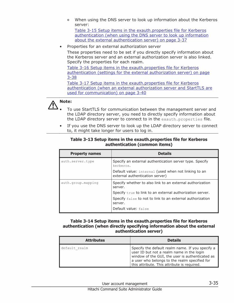
¢ When using the DNS server to look up information about the Kerberosserver:Table 3-15 Setup items in the exauth.properties file for Kerberosauthentication (when using the DNS server to look up informationabout the external authentication server) on page 3-37
• Properties for an external authorization serverThese properties need to be set if you directly specify information aboutthe Kerberos server and an external authorization server is also linked.Specify the properties for each realm.Table 3-16 Setup items in the exauth.properties file for Kerberosauthentication (settings for the external authorization server) on page3-38Table 3-17 Setup items in the exauth.properties file for Kerberosauthentication (when an external authorization server and StartTLS areused for communication) on page 3-40
Note:
• To use StartTLS for communication between the management server andthe LDAP directory server, you need to directly specify information aboutthe LDAP directory server to connect to in the exauth.properties file.
• If you use the DNS server to look up the LDAP directory server to connectto, it might take longer for users to log in.
Table 3-13 Setup items in the exauth.properties file for Kerberosauthentication (common items)
Property names Details
auth.server.type Specify an external authentication server type. Specifykerberos.
Default value: internal (used when not linking to anexternal authentication server)
auth.group.mapping Specify whether to also link to an external authorizationserver.Specify true to link to an external authorization server.
Specify false to not to link to an external authorizationserver.Default value: false
Table 3-14 Setup items in the exauth.properties file for Kerberosauthentication (when directly specifying information about the external
authentication server)
Attributes Details
default_realm Specify the default realm name. If you specify auser ID but not a realm name in the loginwindow of the GUI, the user is authenticated asa user who belongs to the realm specified forthis attribute. This attribute is required.
User account management 3-35Hitachi Command Suite Administrator Guide

Attributes Details
Default value: none
dns_lookup_kdc Specify false.
Default value: falsedefault_tkt_enctypes Specify the encryption type used for Kerberos
authentication. This property is enabled only ifthe management server OS is Windows.You can use the following encryption types:• aes128-cts• rc4-hmac• des3-cbc-sha1• des-cbc-md5• des-cbc-crcIf you want to specify multiple encryption types,use a comma to separate the encryption types.Among the specified encryption types, anencryption type that is supported by both themanagement server OS and a Kerberos serverwill be used.Default value: None (DES-CBC-MD5 is used forauthentication.)
clockskew Specify the acceptable range of differencebetween the management server time andKerberos server time. If the difference exceedsthis value, an authentication error occurs.Specifiable values: 0 to 300 (seconds)Default value: 300
timeout Specify the amount of time to wait before timingout when connecting to the Kerberos server. Ifyou specify 0, the system waits until acommunication error occurs without timing out.Specifiable values: 0 to 120 (seconds)Default value: 3
realm_name Specify the realm identification names. You canspecify any name for this attribute in order toidentify which realms the property attributesettings are applied to. You must specify at leastone name. When specifying multiple realmidentification names, separate the names withcommas (,). Do not register the same realmidentification name more than once.Default value: none
value-specified-for-realm_name.realm
Specify the name of the realm set in theKerberos server. This attribute is required.Default value: none
value-specified-for-realm_name.kdc#
Specify the information about the Kerberosserver in the following format:
3-36 User account managementHitachi Command Suite Administrator Guide
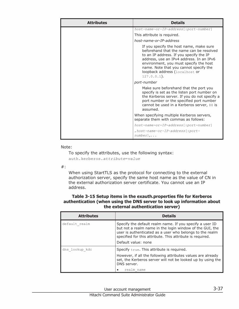
Attributes Detailshost-name-or-IP-address[:port-number]This attribute is required.host-name-or-IP-address
If you specify the host name, make surebeforehand that the name can be resolvedto an IP address. If you specify the IPaddress, use an IPv4 address. In an IPv6environment, you must specify the hostname. Note that you cannot specify theloopback address (localhost or127.0.0.1).
port-numberMake sure beforehand that the port youspecify is set as the listen port number onthe Kerberos server. If you do not specify aport number or the specified port numbercannot be used in a Kerberos server, 88 isassumed.
When specifying multiple Kerberos servers,separate them with commas as follows:host-name-or-IP-address[:port-number],host-name-or-IP-address[:port-number],...
Note:To specify the attributes, use the following syntax:auth.kerberos.attribute=value
#:When using StartTLS as the protocol for connecting to the externalauthorization server, specify the same host name as the value of CN inthe external authorization server certificate. You cannot use an IPaddress.
Table 3-15 Setup items in the exauth.properties file for Kerberosauthentication (when using the DNS server to look up information about
the external authentication server)
Attributes Details
default_realm Specify the default realm name. If you specify a user IDbut not a realm name in the login window of the GUI, theuser is authenticated as a user who belongs to the realmspecified for this attribute. This attribute is required.Default value: none
dns_lookup_kdc Specify true. This attribute is required.
However, if all the following attributes values are alreadyset, the Kerberos server will not be looked up by using theDNS server.• realm_name
User account management 3-37Hitachi Command Suite Administrator Guide

Attributes Details
• value-specified-for-realm_name.realm• value-specified-for-realm_name.kdc
default_tkt_enctypes Specify the encryption type used for Kerberosauthentication. This property is enabled only if themanagement server OS is Windows.You can use the following encryption types:• aes128-cts• rc4-hmac• des3-cbc-sha1• des-cbc-md5• des-cbc-crcIf you want to specify multiple encryption types, use acomma to separate the encryption types.Among the specified encryption types, an encryption typethat is supported by both the management server OS anda Kerberos server will be used.Default value: None (DES-CBC-MD5 is used forauthentication.)
clockskew Specify the acceptable range of difference between themanagement server time and Kerberos server time. If thedifference exceeds this value, an authentication erroroccurs.Specifiable values: 0 to 300 (seconds)Default value: 300
timeout Specify the amount of time to wait before timing out whenconnecting to the Kerberos server. If you specify 0, thesystem waits until a communication error occurs withouttiming out.Specifiable values: 0 to 120 (seconds)Default value: 3
Note:To specify the attributes, use the following syntax:auth.kerberos.attribute=value
Table 3-16 Setup items in the exauth.properties file for Kerberosauthentication (settings for the external authorization server)
Attributes Details
protocol# Specify the protocol for connecting to the LDAP directory server.When communicating in plain text format, specify ldap. Whenusing StartTLS communication, specify tls. StartTLScommunication can be used only when directly specifyinginformation about the Kerberos server.Before specifying tls, make sure that one of the followingencryption methods can be used on the LDAP directory server.
3-38 User account managementHitachi Command Suite Administrator Guide

Attributes Details
• TLS_RSA_WITH_AES_256_CBC_SHA256• TLS_RSA_WITH_AES_256_CBC_SHA• TLS_RSA_WITH_AES_128_CBC_SHA256• TLS_RSA_WITH_AES_128_CBC_SHA• SSL_RSA_WITH_3DES_EDE_CBC_SHASpecifiable values: ldap or tlsDefault value: ldap
port Specify the port number of the LDAP directory server. Make surebeforehand that the port you specify is set as the listen portnumber on the LDAP directory server.Specifiable values: 1 to 65535Default value: 389
basedn Specify the BaseDN, which is the DN of the entry that will be usedas the start point when searching for LDAP user information on theLDAP directory server. The user entries that are located in thehierarchy below this DN will be checked during authorization.Specify the DN of the hierarchy that includes all of the user entriesto be searched.Specify the DN by following the rules defined in RFC4514. Forexample, if any of the following characters are included in a DN,you need to use a backslash (\) to escape each character.
Spaces # + ; , < = > \If characters that need to be escaped are included in the specifiedBaseDN, escape all of those characters correctly because thespecified value will be passed to the LDAP directory server withoutchange.If you omit this attribute, the value specified in thedefaultNamingContext property of Active Directory is assumed asthe BaseDN.Default value: none
timeout Specify the amount of time to wait before timing out whenconnecting to the LDAP directory server. If you specify 0, thesystem waits until a communication error occurs without timingout.Specifiable values: 0 to 120 (seconds)Default value: 15
retry.interval Specify the retry interval (in seconds) for when an attempt toconnect to the LDAP directory server fails.Specifiable values: 1 to 60 (seconds)Default value: 1
retry.times Specify the number of retries to attempt when an attempt toconnect to the LDAP directory server fails. If you specify 0, noretries are attempted.Specifiable values: 0 to 50Default value: 20
User account management 3-39Hitachi Command Suite Administrator Guide

Note:To specify the attributes, use the following syntax:auth.group.realm-name.attribute=valueFor realm-name, specify the value specified forauth.kerberos.realm_name-property-value.realm.
#:When communicating by using StartTLS as the protocol for connecting tothe LDAP directory server, you need to specify the security settings ofCommon Component.
Table 3-17 Setup items in the exauth.properties file for Kerberosauthentication (when an external authorization server and StartTLS are
used for communication)
Property Details
auth.ocsp.enable Specify whether or not to verify the validity of an LDAPdirectory server's electronic signature certificate by using anOCSP responder when the LDAP directory server andStartTLS are used for communication.If you want to verify the validity of certificates, specify true.To not verify the validity of certificates, specify false.
Default value: falseauth.ocsp.responderURL Specify the URL of an OCSP responder if you want to use an
OCSP responder that is not the one written in the AIA field ofthe electronic signature certificate to verify the validity of theelectronic signature certificate. If this value is omitted, theOCSP responder written in the AIA field is used.Default value: None
Examples of setting the exauth.properties file for Kerberos authentication
Examples of how to set the exauth.properties file when using a Kerberosserver to perform authentication are provided below.
• When directly specifying information about a Kerberos server (when notlinking to an external authorization server):
auth.server.type=kerberosauth.group.mapping=falseauth.kerberos.default_realm=EXAMPLE.COMauth.kerberos.dns_lookup_kdc=falseauth.kerberos.clockskew=300auth.kerberos.timeout=3auth.kerberos.realm_name=RealmNameauth.kerberos.RealmName.realm=EXAMPLE.COMauth.kerberos.RealmName.kdc=kerberos.example.com:88
• When using the DNS server to look up a Kerberos server (when notlinking to an external authorization server):
auth.server.type=kerberosauth.group.mapping=false
3-40 User account managementHitachi Command Suite Administrator Guide

auth.kerberos.default_realm=EXAMPLE.COMauth.kerberos.dns_lookup_kdc=trueauth.kerberos.clockskew=300auth.kerberos.timeout=3
• When directly specifying information about a Kerberos server (when alsolinking to an external authorization server):
auth.server.type=kerberosauth.group.mapping=trueauth.ocsp.enable=falseauth.ocsp.responderURL=auth.kerberos.default_realm=EXAMPLE.COMauth.kerberos.dns_lookup_kdc=falseauth.kerberos.clockskew=300auth.kerberos.timeout=3auth.kerberos.realm_name=RealmNameauth.kerberos.RealmName.realm=EXAMPLE.COMauth.kerberos.RealmName.kdc=kerberos.example.com:88auth.group.EXAMPLE.COM.protocol=ldapauth.group.EXAMPLE.COM.port=389auth.group.EXAMPLE.COM.basedn=dc=Example,dc=comauth.group.EXAMPLE.COM.timeout=15auth.group.EXAMPLE.COM.retry.interval=1auth.group.EXAMPLE.COM.retry.times=20
• When using the DNS server to look up a Kerberos server (when alsolinking to an external authorization server):
auth.server.type=kerberosauth.group.mapping=trueauth.kerberos.default_realm=EXAMPLE.COMauth.kerberos.dns_lookup_kdc=trueauth.kerberos.clockskew=300auth.kerberos.timeout=3
About a LDAP search user accountAn LDAP search user account is used when an account needs to beauthenticated or authorized, or when searching for information within anLDAP directory server.
In the following cases, you need to register an LDAP search user account onthe management server.
• When an LDAP directory server is used as an external authenticationserver and the data structure is the hierarchical structure model
• When an LDAP directory server is used as an external authorizationserver#
In cases other than above, this step is not necessary, because LDAP userinformation is not searched during authentication and authorization. If a useraccount used to search for LDAP user information has been alreadyregistered, delete it.
#:When registering an authorization group in Hitachi Command Suiteproducts by using the GUI, if you want to check whether the distinguished
User account management 3-41Hitachi Command Suite Administrator Guide

name of the authorization group is registered on the externalauthorization server by using a user ID such as the System accountregistered in Hitachi Command Suite products, you need to register auser account used to search for LDAP user information on themanagement server.
Conditions for LDAP search user account
Conditions for the LDAP search user account vary depending on theauthentication method.
Prepare a user account that satisfies the following conditions on the LDAPdirectory server.
For LDAP authentication:
¢ The user account can bind to the DN specified forauth.ldap.auth.server.name-property-value.basedn in theexauth.properties file
¢ The user account can search the attributes for all entries below theDN specified for auth.ldap.auth.server.name-property-value.basedn in the exauth.properties file
¢ The user account can reference the DN specified forauth.ldap.auth.server.name-property-value.basedn in theexauth.properties file
¢ The user account can reference the authorization groups that areunder the DN specified for auth.ldap.auth.server.name-property-value.basedn in the exauth.properties file (when an externalauthorization server is also linked to)
¢ The user account can search the attributes of the authorization groupsthat are under the DN specified for auth.ldap.auth.server.name-property-value.basedn in the exauth.properties file and searchthe attributes of nested groups of the authorization groups (when anexternal authorization server is also linked to)
For RADIUS authentication:
¢ The user account can bind to the DN specified forauth.group.domain-name.basedn in the exauth.properties file
¢ The user account can search the attributes for all entries below theDN specified for auth.group.domain-name.basedn in theexauth.properties file
¢ The user account can reference the DN specified forauth.group.domain-name.basedn in the exauth.properties file
¢ The user account can reference the authorization groups that areunder the DN specified for auth.group.domain-name.basedn in theexauth.properties file.
¢ The user account can search the attributes of the authorization groupsthat are under the DN specified for auth.group.domain-name.basedn
3-42 User account managementHitachi Command Suite Administrator Guide

in the exauth.properties file and search the attributes of nestedgroups of the authorization groups
For Kerberos authentication:
¢ The user account can bind to the DN specified for auth.group.realm-name.basedn in the exauth.properties file
¢ The user account can search the attributes for all entries below theDN specified for auth.group.realm-name.basedn in theexauth.properties file
¢ The user account can reference the DN specified forauth.group.realm-name.basedn in the exauth.properties file
¢ The user account can reference the authorization groups that areunder the DN specified for auth.group.realm-name.basedn in theexauth.properties file
¢ The user account can search the attributes of the authorization groupsthat are under the DN specified for auth.group.realm-name.basednin the exauth.properties file and search the attributes of nestedgroups of the authorization groups
Registering an LDAP search user account
Use the hcmds64ldapuser command to register the an LDAP search useraccount on the management server.
Operations to complete in advance
Register an LDAP search user on the LDAP directory server.
Information to collect in advance
• DN and password of the LDAP search user• Server identification name of the LDAP directory server (for LDAP
authentication)Specify the server identification name that was specified for theauth.server.name property in the exauth.properties file.
• Domain name of the RADIUS server (for RADIUS authentication)Specify the domain name specified for auth.radius.auth.server.name-property-value.domain.name in the exauth.properties file.
• Realm name of the Kerberos server (for Kerberos authentication)If you directly specify information about a Kerberos server in theexauth.properties file, specify the value specified forauth.kerberos.default_realm orauth.kerberos.auth.kerberos.realm_name-property-value.realm.If you specify the settings in the exauth.properties file to use the DNSserver to look up information about a Kerberos server, specify the realmname registered in the DNS server.
User account management 3-43Hitachi Command Suite Administrator Guide

To register an LDAP search user account:
1. Execute the hcmds64ldapuser command.
In Windows:installation-folder-for-Hitachi-Command-Suite\Base64\bin\hcmds64ldapuser /set /dn DN-of-user-account-used-to-search-for-LDAP-user-info [/pass password-of-user-account-used-to-search-for-LDAP-user-info] /name name
In Linux:installation-directory-for-Hitachi-Command-Suite/Base64/bin/hcmds64ldapuser -set -dn DN-of-user-account-used-to-search-for-LDAP-user-info [-pass password-of-user-account-used-to-search-for-LDAP-user-info] -name name
¢ DN-of-user-account-used-to-search-for-LDAP-user-infoSpecify a DN by following the rules defined in RFC4514. For example,if the following characters are included in a DN, you need to use abackslash (\) to escape each character.Spaces # + , ; < = > \
¢ password-of-user-account-used-to-search-for-LDAP-user-infoThis is case-sensitive and must exactly match the password registeredin the LDAP directory server. If you execute the command withoutspecifying the pass option, you will be prompted to enter a password.
Note:
• In the LDAP directory server, you can use double quotation marks (") forthe DN and password. In the management server, however, you need toregister a user account whose DN and password do not include doublequotation marks.
• If you are using Active Directory, you can use the dsquery commandprovided by Active Directory to check the DN of a user. The followingexample shows how to use the dsquery command to check the DN of theuser administrator, and also shows the execution results:dsquery user -name administrator"CN=administrator,CN=admin,DC=example,DC=com"
• If the DN includes commas such ascn=administrator,cn=admin,dc=example,com, specify as follows:In Windows:hcmds64ldapuser /set /dn "cn=administrator,cn=admin,dc=example\,com" /pass administrator_pass /name ServerNameIn Linux:hcmds64ldapuser -set -dn "cn=administrator,cn=admin,dc=example\\,com" -pass administrator_pass -name ServerName
3-44 User account managementHitachi Command Suite Administrator Guide

Related topics
• Notes on commands for setting up a link to an external authenticationserver on page 3-49
Deleting an LDAP search user account
Use the hcmds64ldapuser command to delete the LDAP search user accountfrom the management server.
Information to collect in advance
• Server identification name of the LDAP directory server (for LDAPauthentication)
• Domain name of the RADIUS server (for RADIUS authentication)• Realm name of the Kerberos server (for Kerberos authentication)
To delete an LDAP search user account:
1. Execute the hcmds64ldapuser command.
In Windows:installation-folder-for-Hitachi-Command-Suite\Base64\bin\hcmds64ldapuser /delete /name name
In Linux:installation-directory-for-Hitachi-Command-Suite/Base64/bin/hcmds64ldapuser -delete -name name
Related topics
• Notes on commands for setting up a link to an external authenticationserver on page 3-49
Checking the LDAP directory server that registered LDAP search user account
Use the hcmds64ldapuser command to check which LDAP directory serverhas registered the LDAP search user account on the management server.
To check the LDAP directory server that registered the LDAP searchuser account:
1. Execute the hcmds64ldapuser command.
In Windows:installation-folder-for-Hitachi-Command-Suite\Base64\bin\hcmds64ldapuser /list
In Linux:installation-directory-for-Hitachi-Command-Suite/Base64/bin/hcmds64ldapuser -list
User account management 3-45Hitachi Command Suite Administrator Guide

Registering a shared secretUse the hcmds64radiussecret command to register the RADIUS sharedsecret on the management server.
Information to collect in advance
• Shared secret• RADIUS server indication name
RADIUS-server-indication-name must match a server indication namespecified for the auth.server.name property in the exauth.propertiesfile.
To register a shared secret:
1. Execute the hcmds64radiussecret command.
In Windows:installation-folder-for-Hitachi-Command-Suite\Base64\bin\hcmds64radiussecret [/set shared-secret] /name RADIUS-server-indication-name
In Linux:installation-directory-for-Hitachi-Command-Suite/Base64/bin/hcmds64radiussecret [-set shared-secret] -nameRADIUS-server-indication-name
¢ If you execute the command without specifying the set option, youwill be prompted to enter a shared secret.
Related topics
• Notes on commands for setting up a link to an external authenticationserver on page 3-49
Deleting a shared secret
Use the hcmds64radiussecret command to delete the shared secret.
Information to collect in advance
RADIUS server indication name.
To delete a shared secret:
1. Execute the hcmds64radiussecret command.
In Windows:installation-folder-for-Hitachi-Command-Suite\Base64\bin\hcmds64radiussecret /delete /name RADIUS-server-indication-name
In Linux:
3-46 User account managementHitachi Command Suite Administrator Guide

installation-directory-for-Hitachi-Command-Suite/Base64/bin/hcmds64radiussecret -delete -name RADIUS-server-indication-name
Related topics
• Notes on commands for setting up a link to an external authenticationserver on page 3-49
Checking the RADIUS server that registered a shared secret on the managementserver
Use the hcmds64radiussecret command to check which RADIUS server hasregistered the shared secret on the management server.
To check the RADIUS server that registered a shared secret on themanagement server:
1. Execute the hcmds64radiussecret command.
In Windows:installation-folder-for-Hitachi-Command-Suite\Base64\bin\hcmds64radiussecret /list
In Linux:installation-directory-for-Hitachi-Command-Suite/Base64/bin/hcmds64radiussecret -list
The server identification name of the RADIUS server is displayed.
Related topics
• Notes on commands for setting up a link to an external authenticationserver on page 3-49
Checking connections to an external authentication server and anexternal authorization server
Use the hcmds64checkauth command to check whether the managementserver is correctly connected to the external authentication server and theexternal authorization server.
If Tuning Manager is remotely connected, perform this operation on thecomputer on which the Device Manager server is installed.
Operations to complete in advance
Register an external authentication server and an external authorizationserver (see Registering an external authentication server and an externalauthorization server on page 3-17).
User account management 3-47Hitachi Command Suite Administrator Guide

Information to collect in advance
• For LDAP authenticationCheck the user accounts registered on the LDAP directory server. For userIDs, specify the value saved in the attribute specified byauth.ldap.value-specified-in-auth.server.name.attr in theexauth.properties file.
• For RADIUS authenticationCheck the user accounts registered on the RADIUS server.
• For Kerberos authentication
When linking only to an external authentication server:Check the user accounts that are registered in Hitachi Command Suiteproducts and whose authentication method is Kerberosauthentication.
When also linking to an external authorization server:Check the user accounts not registered in Hitachi Command Suiteproducts.
In addition, if you specify a user who belongs to a realm other than therealm specified for default_realm in the exauth.properties file, alsocheck the realm that the user belongs to.
Note that you cannot specify a user account whose user-ID or passwordbegins with a forward slash (/) in Windows, or hyphen (-) in Linux.
To check connections to an external authentication server and anexternal authorization server:
1. Execute the hcmds64checkauth command.
In Windows:installation-folder-for-Hitachi-Command-Suite\Base64\bin\hcmds64checkauth [/user user-ID /pass password] [/summary]
In Linux:installation-directory-for-Hitachi-Command-Suite/Base64/bin/hcmds64checkauth [-user user-ID -pass password][-summary]
¢ If you execute the command without specifying the user option or thepass option, you will be prompted to enter a user ID and password.
¢ If you execute the command with the summary option specified, theconfirmation message is displayed in summary format.
Note: When using the Kerberos authentication method, if more than onerealm name is specified in the exauth.properties file, check by realm name.In addition, specify user IDs according to the following:
• If you specify a user who belongs to a realm other than the realm set fordefault_realm in the exauth.properties file:Specify a character string that contains the realm name.
3-48 User account managementHitachi Command Suite Administrator Guide
• If you specify a user who belongs to the realm set for default_realm inthe exauth.properties file:You can omit the realm name.
Settings in the exauth.properties file and connections to the externalauthentication server and external authorization server are checked, andcheck results are displayed in each of four phases. The following message isdisplayed if the checking in each phase finishes normally.
KAPM15004-I The result of the configuration check of Phase phase-number was normal.
Phase 1The command verifies that common properties have been correctlyspecified in the exauth.properties file.
Phase 2The command verifies that the properties for the external authenticationserver and properties for the external authorization server have beencorrectly specified in the exauth.properties file.
Phase 3The command verifies that the external authentication server can beconnected to.
Phase 4If an external authorization server is also linked to, the command verifiesthat the external authorization server can be connected to andauthorization groups can be searched.
If an error occurs, find the output message ID in the Hitachi Command SuiteMessages, and check the cause and action to take for the error.
Related topics
• Notes on commands for setting up a link to an external authenticationserver on page 3-49
Notes on commands for setting up a link to an externalauthentication server
If command line control characters are included in the arguments ofcommands that will be executed when specifying the settings to link to anexternal authentication server, escape the characters correctly according tothe specifications of the command line.
Also, you need to pay attention to backslashes (\) included in the argumentsbecause they are treated specially in the command line.
The following explains how to escape when executing the hcmds64ldapusercommand, hcmds64radiussecret command, or hcmds64checkauthcommand.
User account management 3-49Hitachi Command Suite Administrator Guide

In Windows:If the following characters are included in an argument, enclose theargument in double quotation marks (") or use a caret (^) to escape eachcharacter:Spaces & | ^ < > ( )A backslash might be treated as an escape character depending on thecharacter that follows it. Therefore, if a backslash and any of the abovecharacters are included in an argument, use a caret to escape eachcharacter rather than enclose the argument in double quotation marks.Also, if there is a backslash at the end of an argument, escape it by usinganother backslash.
In Linux:If the following characters are included in an argument, enclose theargument in double quotation marks or use a backslash to escape eachcharacter:Spaces # & ' ( ) ~ \ ` < > ; |Note that a backslash in an argument is treated as an escape charactereven if the argument is enclosed in double quotation marks. If abackslash is included in an argument, escape it by using anotherbackslash.
For example, if a shared secret to be registered by the hcmds64radiussecretcommand is secret01\, escape it as follows:
In Windows:hcmds64radiussecret /set secret01\\ /name ServerName
In Linux:Use either of the following formats:hcmds64radiussecret -set secret01\\ -name ServerNamehcmds64radiussecret -set "secret01\\" -name ServerName
Encryption types for Kerberos authenticationConfigure the Kerberos server so that the encryption types supported byHitachi Command Suite products can be used.
In Hitachi Command Suite products, the encryption types listed below can beused for Kerberos authentication.
• AES256-CTS-HMAC-SHA1-96• AES128-CTS-HMAC-SHA1-96• RC4-HMAC• DES3-CBC-SHA1• DES-CBC-CRC• DES-CBC-MD5
3-50 User account managementHitachi Command Suite Administrator Guide

4Security
This chapter describes the security settings required to operate HitachiCommand Suite products.
□ Login warning banners
□ Communication security mode
□ Controlling management client access to the management server
□ Changing the password-encoding level in the Device Manager CLI and theTiered Storage Manager CLI
Security 4-1Hitachi Command Suite Administrator Guide

Login warning bannersA warning banner is a field for security messages displayed in the Loginwindow of Hitachi Command Suite products.
Hitachi Command Suite products can display an optional message (warningbanner), as a security risk measure at login. Issuing a warning beforehand tothird parties that might attempt illegal access can help reduce the risk ofproblems such as data loss or information leakage.
Conditions that apply when displaying warning banner messagesWhen you use the hcmds64banner command to register a message to bedisplayed on a warning banner, there are restrictions on the number ofcharacters and character codes.
• Use HTML tags to create a message. In addition to the usual characters,you can use HTML tags to change font attributes or place line breaks indesired locations.The following conditions apply to the use of HTML tags:
¢ To use line breaks in a desired location, use the HTML tag <BR>.¢ To display a character used in HTML syntax (for example, < > " ' &),
use the HTML escape sequence. For example, to display anampersand (&) in the Login window, write & in the HTML file.
• No more than 1,000 characters can be used. (HTML tag characters arealso counted in the number of characters.)
• Usable characters are from the Unicode UTF-8 encoding.
Creating and registering a message displayed on a warning bannerUse a text editor to create a message displayed on a warning banner forHitachi Command Suite programs, and execute the hcmds64banner commandto register it.
Operations to complete in advance
Log in as a user with Administrator permissions (for Windows) or as a rootuser (for Linux).
To create and register a message displayed on a warning banner:
1. Use a text editor to create a message.Sample messages in English (bannermsg.txt) and Japanese(bannermsg_ja.txt) are provided in the following locations:
¢ In Windows:installation-folder-for-Hitachi-Command-Suite\Base64\sample\resource
¢ In Linux:
4-2 SecurityHitachi Command Suite Administrator Guide

installation-directory-for-Hitachi-Command-Suite/Base64/sample/resource
These sample files are overwritten at installation so, if you wish to use asample file, copy it and then edit it.The following shows the default message:
<center><b>Warning Notice!</b></center>This is a {Company Name Here} computer system, which may be accessed and used only for authorized {Company Name Here} business by authorized personnel. Unauthorized access or use of this computer system may subject violators to criminal, civil, and/or administrative action. <br>All information on this computer system may be intercepted, recorded, read, copied, and disclosed by and to authorized personnel for official purposes, including criminal investigations. Such information includes sensitive data encrypted to comply with confidentiality and privacy requirements. Access or use of this computer system by any person, whether authorized or unauthorized, constitutes consent to these terms. There is no right of privacy in this system.
2. Execute the hcmds64banner command to register the message :
¢ In Windows:installation-folder-for-Hitachi-Command-Suite\Base64\bin\hcmds64banner /add /file file-name [/locale locale-name]
¢ In Linux:installation-directory-for-Hitachi-Command-Suite/Base64/bin/hcmds64banner -add -file file-name [-localelocale-name]
file-nameUsing an absolute path, specify the file that stores the message. InLinux, do not specify a path that includes a space.
locale-nameSpecify the locale of the language used for the message (for example,en for English, or ja for Japanese). If this setting is omitted, theregistered message will always be displayed in the warning bannerregardless of the locale (the message is registered as a message ofthe default locale).When the GUI is used in multiple locales, if you register a messagewith the same contents in a different language for each locale, themessage can be automatically switched to match the locale of the webbrowser.When multiple languages are specified on one web browser, the localeof the warning banner is determined by the language priority settingsof the web browser.
Note: If you execute the hcmds64banner command and a message for thespecified locale is already registered, it will be updated by being overwritten.
Tip: You can also use the GUI to perform the following operations:
• Registering a message without the locale specified
Security 4-3Hitachi Command Suite Administrator Guide

• Editing a message that has been registered by the hcmds64bannercommand with the locale option omitted
When you use the GUI to perform operations, the following restrictions apply:
• Available HTML tags are limited.• If the system is in a cluster configuration, the message is registered only
to the executing node. To register the message to the standby node,switch the nodes, and then perform the same operations.
The message is registered in the management server and displayed in theLogin window of Hitachi Command Suite products.
Deleting a message from the warning bannerExecute the hcmds64banner command to delete a message displayed in thewarning banner of Hitachi Command Suite products.
Operations to complete in advance
Log in as a user with Administrator permissions (for Windows) or as a rootuser (for Linux).
Information to collect in advance
The locale of the message to be deleted (en for English or ja for Japanese).
To delete a message:
1. Execute the hcmds64banner command:
¢ In Windows:installation-folder-for-Hitachi-Command-Suite\Base64\bin\hcmds64banner /delete [/locale locale-name]
¢ In Linux:installation-directory-for-Hitachi-Command-Suite/Base64/bin/hcmds64banner -delete [-locale locale-name]
locale-nameSpecify the locale of the message to be deleted (en for English or jafor Japanese). If omitted, the default locale will be specified.
Tip: You can also use the GUI to delete the following messages:
• A message registered from the GUI• A message registered by the hcmds64banner command with the locale
option omittedIf the system is in a cluster configuration, operations from the GUI areapplied only to the executing node. To apply the operation to the standbynode, switch the nodes and then perform the same operations.
4-4 SecurityHitachi Command Suite Administrator Guide

Communication security modeHitachi Command Suite products can enhance communication securitybetween computers in networks by using SSL or TLS.SSL/TLS has thefollowing main functions:
• Verifies the identities of connecting applications• Encrypts data transferred between servers and clients• Detects data that was tampered with during transfers
Secure communication for Device Manager and Tiered StorageManager
Device Manager and Tiered Storage Manager can use SSL/TLS for the inter-machine communications listed below.
Security 4-5Hitachi Command Suite Administrator Guide

Figure 4-1 Secure communication routes for Device Manager and TieredStorage Manager
4-6 SecurityHitachi Command Suite Administrator Guide

• Between a management server and a management client (GUI)SSL/TLS can be used for communication between the components listedbelow.
¢ Common Component and a Web browser¢ The Device Manager server and a Web browser
• Between a management server and a management client (DeviceManager CLI)SSL/TLS can be used for communication between the Device Managerserver and the Device Manager CLI.
• Between a management server and a management client (Tiered StorageManager CLI)SSL/TLS can be used for communication between the Tiered StorageManager server and the Tiered Storage Manager CLI.
• Between an LDAP directory server and a management serverStartTLS can be used for communication between an LDAP directoryserver and Common Component.
• Between the Device Manager server and Replication Manager serverSSL/TLS can be used for communication between the Device Managerserver and Replication Manager server.Even in a multi-site configuration, SSL/TLS can be used forcommunication between each of the secondary sites (Device Managerserver) and each of the primary sites (Replication Manager server).
• Between the Tuning Manager server and Device Manager serverSSL/TLS can be used for communication between the Tuning Managerserver and Device Manager server when both are on the samemanagement server. The Tuning Manager server communicates with theDevice Manager server via the Common Component using SSL/TLS.If the Tuning Manager server and Device Manager server are installed ondifferent management servers, SSL/TLS communication between thosemanagement servers is not possible.
• Between a Host Data Collector machine and a management serverSSL/TLS can be used for communication between Host Data Collector andthe Device Manager server.
• Between a virtualization server and Host Data CollectorIf Host Data Collector is used to manage a virtualization server, SSL/TLScan be used for communication between a virtualization server and HostData Collector.
• Between a management server and a Device Manager agent computerSSL/TLS can be used for communication between the Device Managerserver and a Device Manager agent.
• Between a storage system and a management serverIf the Device Manager server is used as an SSL client, SSL/TLS can beused for communication between the following storage systems and theDevice Manager server:
Security 4-7Hitachi Command Suite Administrator Guide

SSL/TLS is always used for communication with VSP G1000, VirtualStorage Platform, Universal Storage Platform V/VM, Hitachi USP, or HUSVM.
¢ VSP G1000#
¢ Virtual Storage Platform¢ Universal Storage Platform V/VM¢ Hitachi USP¢ HUS VM¢ HUS100¢ Hitachi AMS2000¢ Hitachi SMS¢ SMI-S enabled storage systems (SMI-S provider)
#:If the Device Manager server is used as the SSL server (if useraccounts are authenticated in Hitachi Command Suite when logging into CCI or the SVP), you need to configure settings to use SSL/TLS forcommunication between the Device Manager server and the storagesystem (VSP G1000).
• Between a storage system and a management client (GUI)SSL/TLS can be used for communication between the Web browser of amanagement client and a storage system if Storage Navigator or StorageNavigator Modular 2 is used from the Device Manager GUI.
• Between a Tuning Manager Agent and a Tuning Manager serverSSL/TLS can be used for communication, triggered by use of the TuningManager API, between the Tuning Manager server and a Tuning ManagerAgentNote that the Tuning Manager Agent REST API component in Figure 4-1Secure communication routes for Device Manager and Tiered StorageManager on page 4-6 is a component required for using the TuningManager API, and "Tuning Manager Agent REST API component" is usedas a general term for Tuning Manager - Agent REST Web Service andTuning Manager - Agent REST Application Service.
• Between a Tuning Manager server and a Tuning Manager API clientSSL/TLS can be used for communication between the Tuning Managerserver and a Tuning Manager API client if the Tuning Manager API is used.A Tuning Manager server communicates with a Tuning Manager API clientby using SSL/TLS via the Common Component.
• Between a management server and a CIM clientThe Device Manager server that acts as the CIM server of CIM/WBEM canuse SSL/TLS to communicate with a CIM client for object operations orevent indications.
¢ Object operationsThe Device Manager server acts as an SSL server, and a CIM clientacts as an SSL client.
4-8 SecurityHitachi Command Suite Administrator Guide

¢ Event indicationsThe Device Manager server acts as an SSL client and a CIM client actsas an SSL server.
To further improve security, you can enable two-way authentication.
Note: Hitachi Command Suite products support SSL version 3 and TLSversion 1.2. However, for the following communication routes where theDevice Manager server acts as an SSL client, SSL version 3 or TLS version1.0 is used.
• Between HUS100, Hitachi AMS2000, or Hitachi SMS and a managementserver
• Between Tiered Storage Manager CLI and a management server (If theJDK bundled with Hitachi Command Suite is used )
For the following communication routes where the Device Manager serveracts as an SSL client, if Oracle JDK7 (1.7.0) is used, SSL version 3 or TLSversion 1.0 is used:
• Between VSP G1000, Virtual Storage Platform, Universal Storage PlatformV/VM, Hitachi USP, HUS VM, or SMI-S enabled storage system (SMI-Sprovider) and a management server
• Between a CIM client and a management server
Operation workflow for secure communication between a management serverand a management client (GUI)
You need to create server certificates for Common Component and the DeviceManager server on the management server, and then import them into theWeb browser in the management client (GUI).
Security 4-9Hitachi Command Suite Administrator Guide

Figure 4-2 Operation workflow for secure communication between amanagement server and a management client (GUI)
4-10 SecurityHitachi Command Suite Administrator Guide

Note:
• You do not need to create and import a server certificate for the DeviceManager server if you do not use Storage Navigator or Storage NavigatorModular 2 from Element Manager in the Device Manager GUI.
• If you want to restrict which cipher suites are used for SSL/TLScommunication, change the value of theserver.https.enabledCipherSuites property in theserver.properties file of the Device Manager server.
Related topics
• Changing the URL for accessing Hitachi Command Suite products(hcmds64chgurl command) on page 2-41
• Configuring an SSL server (Common Component) on page 4-33• Configuring an SSL server (Device Manager server) on page 4-41• Configuring an SSL client on page 4-65• Settings for using Element Manager on page 5-3• Changing Device Manager server properties on page A-4• server.https.enabledCipherSuites on page A-32
Operation workflow for secure communication between a management serverand a management client (Device Manager CLI)
You need to create a server certificate for the Device Manager server on themanagement server, and then enable SSL/TLS in the management client(Device Manager CLI).
Security 4-11Hitachi Command Suite Administrator Guide

Figure 4-3 Operation workflow for secure communication between amanagement server and a management client (Device Manager CLI)
Note: If you want to restrict which cipher suites are used for SSL/TLScommunication, change the value of theserver.https.enabledCipherSuites property in the server.propertiesfile of the Device Manager server.
Related topics
• Configuring an SSL server (Device Manager server) on page 4-41• Configuring an SSL client on page 4-65• Changing Device Manager server properties on page A-4• server.https.enabledCipherSuites on page A-32
Operation workflow for secure communication between a management serverand a management client (Tiered Storage Manager CLI)
The self-signed certificate bundled with the Tiered Storage Manager server isused for SSL/TLS communication between a management server and a
4-12 SecurityHitachi Command Suite Administrator Guide

management client (Tiered Storage Manager CLI). You need to set the TieredStorage Manager server properties on the management server, and thenenable SSL/TLS in the management client (Tiered Storage Manager CLI).
Figure 4-4 Operation workflow for secure communication between amanagement server and a management client (Tiered Storage Manager
CLI)
Note: If you want to restrict which cipher suites are used for SSL/TLScommunication, change the value of the server.rmi.secure property in theserver.properties file of the Tiered Storage Manager server.
Related topics
• Configuring an SSL client on page 4-65• Changing Tiered Storage Manager server properties on page B-2• server.rmi.secure on page B-15• server.rmi.security.port on page B-4• server.rmi.security.enabledCipherSuites on page B-15
Operation workflow for secure communication between an LDAP directoryserver and a management server
You need to specify the settings for linking with an external authenticationserver on the management server, and then import the certificate into thetruststore (ldapcacerts).
Security 4-13Hitachi Command Suite Administrator Guide

Figure 4-5 Operation workflow for secure communication between anLDAP directory server and a management server
If the server certificate was issued by a well-known certificate authority, thecertificate of the certificate authority might already be imported to thetruststore (jssecacerts). In this case, you do not need to import thecertificate into the ldapcacerts truststore.
Related topics
• User management on an external authentication server on page 3-7• Configuring an SSL client on page 4-65
Operation workflow for secure communication between a Device Managerserver and Replication Manager server
You need to create a server certificate for the Device Manager server on themanagement server, and then import it into the truststore (jssecacerts).
4-14 SecurityHitachi Command Suite Administrator Guide

Figure 4-6 Operation workflow for secure communication between aDevice Manager server and Replication Manager server
Note that, if the server certificate was issued by a well-known certificateauthority, the certificate of the certificate authority might already be importedto the truststore (jssecacerts). If this is the case, you do not need to importa certificate for Device Manager server
Note:
• If you want to restrict which cipher suites are used for SSL/TLScommunication, change the value of theserver.https.enabledCipherSuites property in theserver.properties file of the Device Manager server.
Security 4-15Hitachi Command Suite Administrator Guide

• For a multi-site configuration, transfer the Device Manager servercertificate created in each secondary site to the primary site in a securemethod, and then import the certificate into the truststore(jssecacerts).
Related topics
• Configuring an SSL server (Device Manager server) on page 4-41• Configuring an SSL client on page 4-65• Changing Device Manager server properties on page A-4• server.https.enabledCipherSuites on page A-32
Operation workflow for secure communication between a Tuning Managerserver and a Device Manager server
You need to create a server certificate for Common Component on themanagement server, and then import it into the truststore (jssecacerts).
Figure 4-7 Operation workflow for secure communication between aTuning Manager server and a Device Manager server
4-16 SecurityHitachi Command Suite Administrator Guide

Note that for the following case, the certificate might already be imported inthe truststore (jssecacerts). If this is the case, you do not need to import acertificate for Common Component.
• If a well-known certificate authority is used• If closing the port for non-SSL communication for HBase 64 Storage
Mgmt Web Service
Related topics
• Configuring an SSL server (Common Component) on page 4-33• Configuring an SSL client on page 4-65• Changing Device Manager server properties on page A-4• htnm.servers on page A-44• htnm.server.n.host on page A-44• htnm.server.n.protocol on page A-45• htnm.server.n.port on page A-45
Operation workflow for secure communication between a Host Data Collectormachine and a management server
You need to create a server certificate for Host Data Collector on a Host DataCollector machine, and then import it into the truststore (dvmcacerts).
Security 4-17Hitachi Command Suite Administrator Guide

Figure 4-8 Operation workflow for secure communication between a HostData Collector machine and a management server
Note: If there are multiple computers where Host Data Collector is installed,you need to match the communication protocol (SSL or non-SSL) betweenthe management server and all of the Host Data Collector machines.
Related topics
• Registering firewall exceptions for Host Data Collector (Windows) on page2-30
• Configuring an SSL server (Host Data Collector) on page 4-56• Configuring an SSL client on page 4-65• Changing Device Manager server properties on page A-4• hdc.rmiregistry on page A-39• hdc.rmiserver on page A-39
4-18 SecurityHitachi Command Suite Administrator Guide

• hdc.classloader on page A-40• hdc.usessl on page A-41• Changing Host Data Collector properties on page C-2• hdc.ssl.secure on page C-7
Operation workflow for secure communication between a virtualization serverand Host Data Collector
You need to configure an SSL server on a virtualization server, and thenchange the communication protocol used to connect with the virtualizationserver from the Device Manager GUI or CLI.
Figure 4-9 Operation workflow for secure communication between avirtualization server and Host Data Collector
Note: By default, SSL using the self-signed certificate is set to be used forcommunication between a virtualization server and Host Data Collector. Tochange this setting, perform the operation as follows:
• If you want to change the configuration to non-SSL communication foroperation test purposes:If you change to a configuration that uses non-SSL communication (forexample, a configuration for an operation test), first use VMware ESX orVMware vCenter Server to change the security settings (proxy.xml file)
Security 4-19Hitachi Command Suite Administrator Guide

of the Web proxy service, and then use the Device Manager GUI or CLI tochange the communication protocol.
• When using a server certificate issued by a certificate authority:Apply to a certificate authority to obtain a server certificate for avirtualization server. If you are creating a certificate signing request(CSR), specify the IP address of the virtualization server that issued thecertificate as a Subject Alternative Name.If a virtualization server that is managed by Host Data Collector includesthe following, the certificates issued by all the authorities, from theauthority that issued the server certificate for the virtualization server tothe root certificate authority, form a certificate chain, and a servercertificate is required.- VMware ESX 4.x- VMware ESXi 4.x- VMware vCenter Server 4.x- VMware ESXi 5.0, 5.0 Update 1, 5.1- VMware vCenter Server 5.0, 5.0 Update 1b, 5.1, 5.1.0aReplace the obtained server certificate with the self-signed certificate thatis imported to the virtualization server. For details, see VMware manuals.
Related topics
• Importing a certificate into the truststore for Host Data Collector on page4-76
• Changing virtualization server information on page 4-79• Changing Host Data Collector properties on page C-2• hdc.ssl.esx.certCheck on page C-8
Operation workflow for secure communication between a management serverand Device Manager agent
You need to create a server certificate for Device Manager on themanagement server, and then import it into the truststore.
4-20 SecurityHitachi Command Suite Administrator Guide

Figure 4-10 Operation workflow for secure communication between amanagement server and Device Manager agent
Note: If you want to restrict which cipher suites are used for SSL/TLScommunication, change the value of theserver.https.enabledCipherSuites property in the server.propertiesfile of the Device Manager server.
Related topics
• Configuring an SSL server (Device Manager server) on page 4-41• Configuring an SSL client on page 4-65• Changing Device Manager server properties on page A-4• server.https.enabledCipherSuites on page A-32• server.server.serverPort on page D-15
Security 4-21Hitachi Command Suite Administrator Guide

• server.server.ssl.hdvm on page D-22
Operation workflow for secure communication between a storage system and amanagement server
To use SSL/TLS for communication between HUS100, Hitachi AMS2000, orHitachi SMS and a management server, you need to change thecommunication protocol used to connect with storage systems from theDevice Manager GUI or CLI.
You do not need to set up a Device Manager environment for communicationwith VSP G1000, Virtual Storage Platform, Universal Storage Platform V/VM,Hitachi USP, or HUS VM because such communication always uses SSL/TLS.
Figure 4-11 Operation workflow for secure communication between astorage system and a management server
Related topics
• Changing storage system information on page 4-83
Operation workflow for secure communication between a management serverand a storage system (VSP G1000)
To authenticate user accounts in Hitachi Command Suite when logging in toCCI or the SVP, create a server certificate for the Device Manager server, andthen import the certificate into SVP.
4-22 SecurityHitachi Command Suite Administrator Guide

Figure 4-12 Operation workflow for secure communication between amanagement server and a storage system (VSP G1000)
Related topics
• Configuring an SSL server (Device Manager server) on page 4-41• Downloading a Device Manager server truststore file on page 4-65• Registering certificates for HCS on page 4-106
Operation workflow for secure communication between an SMI-S provider and amanagement server
You need to set up an SMI-S provider environment, and then change thecommunication protocol used to connect with the SMI-S provider from theDevice Manager GUI or CLI.
Security 4-23Hitachi Command Suite Administrator Guide

Figure 4-13 Operation workflow for secure communication between anSMI-S provider and a management server
Related topics
• Configuring an SSL client on page 4-65
Operation workflow for secure communication between a Tuning Manager Agentand a Tuning Manager server
You need to create a server certificate on the Tuning Manager Agent host,and then import it into the truststore (jssecacerts).
Figure 4-14 Operation workflow for secure communication between aTuning Manager Agent and a Tuning Manager server
Note that, if the server certificate was issued by a well-known certificateauthority, the certificate of the certificate authority might already be importedto the truststore (jssecacerts). In this case, you do not need to import acertificate.
4-24 SecurityHitachi Command Suite Administrator Guide

Related topics
• Configuring an SSL server (Tuning Manager Agent host) on page 4-60• Configuring an SSL client on page 4-65
Operation workflow for secure communication between a Tuning Managerserver and a Tuning Manager API client
You need to create a Common Component server certificate on themanagement server, and then import the server certificate for the TuningManager API client.Configure the API client-side SSL/TLS settings byperforming the operations appropriate for the environment on each client.
Figure 4-15 Operation workflow for secure communication between aTuning Manager server and a Tuning Manager API client
Related topics
• Configuring an SSL server (Common Component) on page 4-33
Operation workflow for secure communication between a storage system and amanagement client (GUI)
To operate VSP G1000, Virtual Storage Platform, or HUS VM by using StorageNavigator from the Device Manager GUI, you need to re-create a servercertificate for VSP G1000, Virtual Storage Platform, or HUS VM. You do notneed to change the setting when operating other Hitachi storage systems.
When using the server certificate bundled with VSP G1000, Virtual StoragePlatform, or HUS VM, if you launch Storage Navigator from the DeviceManager GUI, an error message is displayed in the Web browser. To avoidthis, you need to create a server certificate in which the IP address of VSPG1000, Virtual Storage Platform, or HUS VM is specified for Common Name.
Security 4-25Hitachi Command Suite Administrator Guide

Figure 4-16 Operation workflow for secure communication between astorage system and a management client (GUI)
Note: The IP address of VSP G1000, Virtual Storage Platform, or HUS VM tobe specified for Common Name in a server certificate must be the same as thestorage system IP address specified when a storage system is registered byusing the Device Manager GUI or CLI.
Related topics
• Configuring an SSL server and clients (VSP G1000) on page 4-84• How to create and import a server certificate (for Virtual Storage Platform
or HUS VM): See the documentation for Storage Navigator.
Operation workflow for secure communication between a management serverand a CIM client (object operations)
To use SSL server authentication for object operations, you need to importthe server certificate created by the Device Manager server into the CIMclient.
4-26 SecurityHitachi Command Suite Administrator Guide

Figure 4-17 Operation workflow for secure communication between amanagement server and a CIM client (object operations)
Note: If you want to restrict which cipher suites are used for SSL/TLScommunication, create a new cimxmlscpa.properties file, and then specifya value for the Ciphers property.
Related topics
• Configuring an SSL server and clients (CIM server) on page 4-108• Configuring an SSL server and clients (CIM client) on page 4-120• Changing Device Manager server properties on page A-4• Ciphers on page A-33
Operation workflow for secure communication between a management serverand a CIM client (two-way authentication for object operations)
For SSL server authentication, import the Device Manager server certificateinto the CIM client. For SSL client authentication, import the CIM clientcertificate into the Device Manager server.
Security 4-27Hitachi Command Suite Administrator Guide

Figure 4-18 Operation workflow for secure communication between amanagement server and a CIM client (two-way authentication for object
operations)
Note: If you want to restrict which cipher suites are used for SSL/TLScommunication, create a new cimxmlscpa.properties file, and then specifya value for the Ciphers property.
Related topics
• Configuring an SSL server and clients (CIM server) on page 4-108• Configuring an SSL server and clients (CIM client) on page 4-120• Changing Device Manager server properties on page A-4• Ciphers on page A-33
4-28 SecurityHitachi Command Suite Administrator Guide

Operation workflow for secure communication between a management serverand a CIM client (event indications)
To use SSL server authentication for event indications, you need to importthe server certificate created by the CIM client into the Device Managerserver.
Figure 4-19 Operation workflow for secure communication between amanagement server and a CIM client (event indications)
Note: If you want to restrict which cipher suites are used for SSL/TLScommunication, create a new cimxmlscpa.properties file, and then specifya value for the Ciphers property.
Related topics
• Configuring an SSL server and clients (CIM server) on page 4-108• Configuring an SSL server and clients (CIM client) on page 4-120• Changing Device Manager server properties on page A-4• Ciphers on page A-33
Operation workflow for secure communication between a management serverand a CIM client (two-way authentication for event indications)
For SSL server authentication, import the server certificate of the CIM clientinto the Device Manager server. For SSL client authentication, import theclient certificate of the Device manager server into the CIM client in the sameway.
Security 4-29Hitachi Command Suite Administrator Guide

Figure 4-20 Operation workflow for secure communication between amanagement server and a CIM client (two-way authentication for event
indications)
Note: If you want to restrict which cipher suites are used for SSL/TLScommunication, create a new cimxmlscpa.properties file, and then specifya value for the Ciphers property.
Related topics
• Configuring an SSL server and clients (CIM server) on page 4-108• Configuring an SSL server and clients (CIM client) on page 4-120• Changing Device Manager server properties on page A-4• Ciphers on page A-33
Truststores
Truststores are stored in the following locations.
• jssecacerts
4-30 SecurityHitachi Command Suite Administrator Guide

The truststore for Common Component. If you use SSL/TLS for thefollowing communication routes, import the certificate into jssecacerts:
¢ Between the Device Manager server and the Replication Managerserver
¢ Between the Tuning Manager server and the Device Manager server¢ Between a Tuning Manager Agent and the Tuning Manager server
(when the Tuning Manager API is used)
In Windows:installation-folder-for-Hitachi-Command-Suite\Base64\uCPSB\jdk\jre\lib\security\jssecacerts
In Linux:installation-directory-for-Hitachi-Command-Suite/Base64/uCPSB/jdk/jre/lib/security/jssecacerts
Note: If the system is linked with Hitachi File Services Manager orStorage Navigator Modular 2, when you close the port for non-SSLcommunication for HBase 64 Storage Mgmt Web Service, also import thecertificate into jssecacerts, which is located in the following location.
• In Windows:installation-folder-for-Hitachi-File-Services-Manager-or-Storage-Navigator-Modular-2\Base\jdk\jre\lib\security\jssecacerts
• In Linux:installation-directory-for-Hitachi-File-Services-Manager-or-Storage-Navigator-Modular-2/Base/jdk/jre/lib/security/jssecacerts
• ldapcacertsThe truststore for Common Component. To use StartTLS to communicatewith an LDAP directory server, import the certificate into ldapcacerts.
In Windows:installation-folder-for-Hitachi-Command-Suite\Base64\conf\sec\ldapcacerts
In Linux:installation-directory-for-Hitachi-Command-Suite/Base64/conf/sec/ldapcacerts
• dvmcacertsThe truststore for the Device Manager server.If you have applied to the certificate authority for a server certificate ofthe Device Manager server that is to be used for communication betweenthe management server and the management client (GUI), import thecertificate returned from the certificate authority into dvmcacerts.To use SSL/TLS for communication between a Host Data Collectormachine and the Device Manager server, import the server certificate forthe Host Data Collector into dvmcacerts.
Security 4-31Hitachi Command Suite Administrator Guide

In Windows:installation-folder-for-Hitachi-Command-Suite\DeviceManager\HiCommandServer\dvmcacerts
In Linux:installation-directory-for-Hitachi-Command-Suite/HiCommandServer/dvmcacerts
Note:
• A truststore file can be changed by using theserver.https.security.truststore property in theserver.properties file of the Device Manager server.
• The initial password is changeit. To change the password, you mustuse HiKeytool. If you use other tools or commands, you will not beable to use HiKeytool to import or view server certificates.
• hdccacertsThe truststore for the Host Data Collector.If you have applied to the certificate authority for a server certificate forthe virtualization server to be used for communication between thevirtualization server and the Host Data Collector, import the certificatereturned from the certificate authority into hdccacerts. The defaultpassword is changeit.
In Windows:installation-folder-for-Host-Data-Collector\HDC\Base\config\hdccacerts
In Linux:installation-directory-for-Host-Data-Collector/HDC/Base/config/hdccacerts
• hdvmcacertsThe truststore for the Device Manager agent.To use SSL/TLS for communication between the management server anda Device Manager agent, import the server certificate for the DeviceManager server into hdvmcacerts. The default password is changeit.
In Windows:installation-folder-for-Device-Manager-agent\agent\config\hdvmcacerts
In Unix:installation-directory-for-Device-Manager-agent/agent/config/hdvmcacerts
• .truststoreThe truststore for object operations of the Device Manager server, whichis used for SSL server authentication to communicate a CIM client. Thedefault password is trustssl.
In Windows:
4-32 SecurityHitachi Command Suite Administrator Guide

installation-folder-for-Hitachi-Command-Suite\DeviceManager\HiCommandServer\wsi\server\jserver\bin\.truststore
In Linux:installation-directory-for-Hitachi-Command-Suite/HiCommandServer/wsi/server/jserver/bin/.truststore
• indtruststoreThe truststore for event indications of the Device Manager server, whichis used for SSL client authentication to communicate with a CIM client.
In Windows:installation-folder-for-Hitachi-Command-Suite\DeviceManager\HiCommandServer\wsi\server\jserver\bin\indtruststore
In Linux:installation-directory-for-Hitachi-Command-Suite/HiCommandServer/wsi/server/jserver/bin/indtruststore
• Java Web Start truststore
In Windows:Program-Files-folder\Java\JRE-version\bin\cacerts
In Linux:/usr/java/JRE-version/javaws/cacerts
In HP-UX:/opt/JRE-version/jre/javaws/cacerts
Related topics
• Changing Device Manager server properties on page A-4• server.https.security.truststore on page A-32
Configuring an SSL server (Common Component)To use Common Component as an SSL server, you need to prepare a privatekey and server certificate, and then specify their storage locations in theuser_httpsd.conf file.
Creating a secret key and a certificate signing request for Common Component
Use the hcmds64ssltool command to create a private key and a certificatesigning request (CSR) in Common Component.
A certificate signing request and self-signed certificate are created with aprivate key size of 2,048 bits. The certificate signing request is created inPEM format. Although you can use this command to create a self-signedcertificate, we recommend that you use a self-signed certificate only to testencrypted communications.
Security 4-33Hitachi Command Suite Administrator Guide
Operations to complete in advance
Log in as a user with Administrator permissions (for Windows) or as a rootuser (for Linux).
Information to collect in advance
• Requirements for the certificate signing request (ask the certificateauthority)
• Version of the Web browser used on the management clientThe signature algorithm of the server certificates must be supported bythe Web browser used on the management client (GUI).
• Existing storage directories for private keys, certificate signing requests,and self-signed certificates (if you recreate them)
Format of the command
In Windows:installation-folder-for-Hitachi-Command-Suite\Base64\bin\hcmds64ssltool /key private-key-file /csr certificate-signing-request-file /cert self-signed-certificate-file /certtext contents-of-a-self-signed-certificate [/validitynumber-of-valid-days] [/dname DN] [/sigalg signature-algorithm]
In Linux:installation-directory-for-Hitachi-Command-Suite/Base64/bin/hcmds64ssltool -key private-key-file -csr certificate-signing-request-file -cert self-signed-certificate-file -certtextcontents-of-a-self-signed-certificate [-validity number-of-valid-days] [-dname DN] [-sigalg signature-algorithm]
Options
keySpecify the path to the location to which a private key will be output. Thesize of a private key is 2,048 bits (fixed).
csrSpecify the path to the location to which the certificate signing requestwill be output.
certSpecify the path to the location to which the self-signed certificate will beoutput.
certtextSpecify the path to the location to which the contents of the self-signedcertificate will be output in text format.
validitySpecify the number of days during which the self-signed certificate isvalid. If this option is omitted, the valid period is set to 3,650 days.
4-34 SecurityHitachi Command Suite Administrator Guide

dnamespecify the DN to be included in the self-signed certificate and certificatesigning request. If you execute the command without specifying thisoption, you will be prompted to specify the DN.To specify the DN, combine each attribute type with the correspondingattribute value into one attribute by using an equal sign (=), and thenspecify the attributes by separating each by a comma. For the DN, youcannot specify a double quotation mark (") or backslash (\). In addition,specify each attribute value as defined by RFC2253. For example, if thespecified DN includes any of the following characters, escape each ofthem by using a backslash (\).A space at the beginning of or at the end of the DNA hash mark (#) at the beginning of the DNA plus sign (+), comma (,), semicolon (;), left angle bracket (<), equalsign (=), or right angle bracket (>)The following table lists and describes the attribute types and valuesspecified for the DN.
Table 4-1 Attribute types and values specified for the DN
Attributetype
Full name of attributetype Attribute value
CN Common Name Specify the host name of themanagement server (HBase 64 StorageMgmt Web Service). This attribute isrequired.Specify the host name used whenconnecting to the management server(HBase 64 Storage Mgmt Web Serviceof Common Component) from themanagement client (GUI). You can alsospecify the host name in FQDN format.If the management server is running ina cluster environment, specify thelogical host name.
OU Organizational Unit Name Specify the name of the organizationalunit.
O Organization Name Specify the organizational name. Thisattribute is required.
L Locality Name Specify the name of the city, town, orother locality.
ST State or Province Name Specify the name of the state orprovince.
C Country Name Specify the two-letter country code.
sigalgSpecify a signature algorithm. You can specify SHA256withRSA,SHA1withRSA, or MD5withRSA. If you omit this specification,SHA256withRSA is used as the signature algorithm.
Security 4-35Hitachi Command Suite Administrator Guide
Caution: When you execute the hcmds64ssltool command, if a file with thesame name already exists in the output location, the existing file will beoverwritten. Therefore, when you recreate a private key, certificate signingrequest, or self-signed certificate, we recommend you to output them to adirectory other than existing storage directories.
Applying to a certificate authority for a Common Component server certificate
Usually, you can apply to a certificate authority for a server certificate online.Send the Common Component certificate signing request (CSR) that youcreated to a certificate authority to be digitally signed.
Operations to complete in advance
Create a certificate signing request for Common Component.
Information to collect in advance
• How to apply to the certificate authority and what they supportYou need to have a server certificate issued in X.509 PEM format. Fordetails about how to apply for a certificate, check the website of thecertificate authority you will use.In addition, make sure that the certificate authority supports thesignature algorithm.
To apply to a certificate authority for a Common Component servercertificate:
1. Send the created certificate signing request to a certificate authority.
Usually, server certificates issued by a certificate authority are sent via email.Make sure that you save the response from the certificate authority.
Note: Certificates issued by a certificate authority have an expiration date.You need to have a certificate reissued before your certificate expires.
Editing the user_httpsd.conf file
To enable SSL/TLS for Common Component or change the host name or portnumber of a management server, edit the user_httpsd.conf file.
Operations to complete in advance
• Create a private key for Common Component (required for enabling SSL/TLS).#
• Prepare a server certificate for Common Component (required forenabling SSL/TLS).#
Prepare the server certificate sent back from the certificate authority.When testing encrypted communications, you can use a self-signedcertificate.
4-36 SecurityHitachi Command Suite Administrator Guide

#:We recommend that you copy the files into the following location.
In Windows:installation-folder-for-Hitachi-Command-Suite\Base64\uCPSB\httpsd\conf\ssl\server
In Linux:installation-directory-for-Hitachi-Command-Suite/Base64/uCPSB/httpsd/conf/ssl/server
Information to collect in advance
• Host name specified for Common Name in the certificate signing request(required for enabling SSL/TLS).
To edit the user_httpsd.conf file:
1. Stop the services of the Hitachi Command Suite product.2. Edit the user_httpsd.conf file.3. Start the services of Hitachi Command Suite product.
Storage location of the user_httpsd.conf file
In Windows:installation-folder-for-Hitachi-Command-Suite\Base64\uCPSB\httpsd\conf\user_httpsd.conf
In Linux:installation-directory-for-Hitachi-Command-Suite/Base64/uCPSB/httpsd/conf/user_httpsd.conf
Example of the user_httpsd.conf file (default)
Security 4-37Hitachi Command Suite Administrator Guide

Settings required for enabling SSL/TLS
• Remove the hash mark (#) at the beginning of the following lines:
• For the ServerName directive on the top line and the ServerName directivewithin the <VirtualHost> tag, specify the host name (for clusterenvironments, specify the logical host name) that you specified forCommon Name in the certificate signing request. Note that host names arecase sensitive.
• For the SSLCertificateKeyFile directive, specify the absolute path tothe private key file for Common Component. Do not specify a symboliclink and junction for the path.
• For the SSLCertificateFile directive, specify the absolute path of theserver certificate for Common Component. For the server certificate, botha signed certificate issued by the certificate authority and a self-signedcertificate exist.
• To use the certificate of the chained certificate authority, remove the hashmark (#) from the beginning of the line for the SSLCACertificateFiledirective, and then specify the absolute path of the certificate of thechained certificate authority. Multiple certificates can be contained in onefile by chaining multiple PEM format certificates by using a text editor.Note that you must not specify a symbolic link or junction for the path.
• For an IPv6 environment, remove the hash mark (#) at the beginning ofthe lines #Listen [::]:22016.
Note:
• Do not edit the httpsd.conf file , the hsso_httpsd.conf file or theuser_hsso_httpsd.conf file.
• Even if you enable SSL or use Device Manager in an IPv6 environment, donot remove or comment out the line Listen 22015.
4-38 SecurityHitachi Command Suite Administrator Guide

To interrupt non-SSL communication from outside the network to themanagement server, add a hash mark (#) at the beginning of the linesListen 22015 and Listen [::]:22015 to comment them out, and thenremove the hash mark at the beginning of the line #Listen127.0.0.1:22015. In this case, if the system is linked with Hitachi FileServices Manager or Storage Navigator Modular 2, make sure that thehost name that is set to the ServerName directive can be resolved to127.0.0.1.If you want to close the port for non-SSL communication that is used forcommunication in the management server, set the port for non-SSLcommunication of HBase 64 Storage Mgmt Web Service to closed.
• If the system is linked with Hitachi File Services Manager or StorageNavigator Modular 2, when you enable SSL/TLS, edit the httpsd.conf filethat is stored in the following location.In Windows:installation-folder-for-Hitachi-File-Services-Manager-or-Storage-Navigator-Modular-2\Base\httpsd\conf\httpsd.confIn Linux:installation-directory-for-Hitachi-File-Services-Manager-or-Storage-Navigator-Modular-2/Base/httpsd/conf/httpsd.confUse the same method to edit the file as you used for theuser_httpsd.conf file. However, for the port number, specify the portnumber for HBase Storage Mgmt Web Service (the default port for non-SSL communication is 23015, and the default port for SSL communicationis 23016).
To disable SSL/TLS, by referencing the example of the user_httpsd.conf file(default), add a hash mark (#) at the beginning of the lines from Listen22016 to </VirtualHost> to comment them out.
Related topics
• Starting the Hitachi Command Suite services on page 8-4• Stopping the Hitachi Command Suite services on page 8-5
Closing the port for the non-SSL communication (HBase 64 Storage Mgmt WebService)
To close the port for non-SSL communication for HBase 64 Storage MgmtWeb Service (default: 22015) that is used for communication in themanagement server, edit the user_httpsd.conf file, and then import thecertificate to the truststore (jssecacerts).
Operations to complete in advance
• Checking the host nameMake sure that the host name specified for Common Name in the servercertificate is the same as the host name set to the ServerName directiveat the beginning of the user_httpsd.conf file.
Security 4-39Hitachi Command Suite Administrator Guide

• Name resolution settingsMake sure that name resolution can be performed from the host name(the host name of the management server) that is set to the ServerNamedirective at the beginning of the user_httpsd.conf file to the IP address.To do this, execute the following command on the management server.ping host-name-of-the-management-server
• Enabling SSL/TLS for Common Component• Setting the properties in the tuningmanager.properties file of the
Device Manager server (when Device Manager is linked with TuningManager)The following properties must be set to SSL:
¢ htnm.server.n.host¢ htnm.server.n.protocol¢ htnm.server.n.port(see htnm.server.n.host on page A-44, htnm.server.n.protocol on pageA-45, htnm.server.n.port on page A-45)
To close the port of the non-SSL communication for HBase 64 StorageMgmt Web Service:
1. Stop the services of the Hitachi Command Suite product.2. Edit the user_httpsd.conf file to comment out the non-SSL
communication port settings.Add a hash mark (#) to the beginning of the line below to turn it into acomment. The following example shows the locations for where to addhash marks (#). This example indicates the default port number.
The user_httpsd.conf file is stored in the following locations:
In Windows:
4-40 SecurityHitachi Command Suite Administrator Guide

installation-folder-for-Hitachi-Command-Suite\Base64\uCPSB\httpsd\conf\user_httpsd.conf
In Linux:installation-directory-for-Hitachi-Command-Suite/Base64/uCPSB/httpsd/conf/user_httpsd.conf
Note: Do not edit the httpsd.conf file.
3. Import the certificate to the truststore (jssecacerts).4. Make sure that the certificate is imported to the truststore.5. Start the services of Hitachi Command Suite product.6. Make sure that you can log in to the Device Manager GUI.
Related topics:
• Importing a certificate into the truststore for Hitachi Command Suite onpage 4-71
• Checking the certificates imported into the truststore for HitachiCommand Suite on page 4-75
• Starting the Hitachi Command Suite services on page 8-4• Stopping the Hitachi Command Suite services on page 8-5
Configuring an SSL server (Device Manager server)To use the Device Manager server as an SSL server, you need to prepare aprivate key and server certificate.
Creating a key pair and a self-signed certificate for Device Manager server
To create a key pair and a self-signed certificate in the Device Managerserver, from the HiKeytool main menu, select SSL configuration for DeviceManager Server, and then Make KeyPair/Self-Signed Certificate.
Use the default values unless you are either very familiar with the field ofcryptography and Java security or are otherwise instructed. We recommendthat you use a self-signed certificate only for testing encryptedcommunications.
Operations to complete in advance
• Log in as a user with Administrator permissions (for Windows) or as aroot user (for Linux).
• Delete the existing key pair (when re-creating a key pair).A keystore can contain only one key pair. A keystore containing two ormore key pairs may cause a problem when the Device Manager server isrunning in secure mode.
Security 4-41Hitachi Command Suite Administrator Guide
Information to collect in advance
• Version of the Web browser used on the management clientThe signature algorithm of the server certificates must be supported bythe Web browser used on the management client (GUI).
To create a key pair and a self-signed certificate for Device Managerserver:
1. Execute the following to start HiKeytool.
In Windows:installation-folder-for-Hitachi-Command-Suite\DeviceManager\HiCommandServer\HiKeytool.bat
In Linux:installation-directory-for-Hitachi-Command-Suite/HiCommandServer/HiKeytool.sh
2. In the main menu, enter 1 (SSL configuration for Device ManagerServer).
3. In the server main menu, enter 1 (Make KeyPair/Self-SignedCertificate) .
4. Enter the host name.Specify the host name used when connecting to the management serverfrom the management client. You can also specify the host name in FQDNformat. If the management server is running in a cluster environment,specify the logical host name.Use the default value unless your computer is visible to the LAN or WANunder a different name, in which case you should use the name by whichthe Device Manager server is visible.
5. Enter the organizational unit .The default value is recommended, but you can use anything that isappropriate, for example, Marketing.
6. Enter your organization name.Ordinarily you would use the default value or your host name, but youcan use another name, such as the name of your company.
7. Enter your city or locality.8. Enter your state or province.
Make sure that you spell it out instead of using an abbreviated code.9. Enter your two-character country code .10. Enter your key alias.
Make sure that you enter the same character string as the host name thatyou specified in step 4.
11. Enter the private key password (minimum of 6 characters ).12. Enter the key algorithm.
Only RSA is supported.13. Enter the key size.
4-42 SecurityHitachi Command Suite Administrator Guide

Only 2048-bit keys are supported.14. Enter the signature algorithm.
SHA256withRSA, SHA1withRSA and MD5withRSA are supported.15. Enter the number of days for which the key pair and self-signed certificate
are valid.16. Enter the keystore password (minimum of 6 characters).17. Restart the Hitachi Command Suite product services for the changes to
take effect.If you will continue to specify other security settings by using HiKeytool,you do not have to restart the services after each setting. Changes willbecome effective when you restart the services after you have finishedspecifying all settings by using HiKeytool.
A key pair and self-signed certificate are created and registered into theDevice Manager server keystore file (default: keystore).
In Windows:installation-folder-for-Hitachi-Command-Suite\DeviceManager\HiCommandServer\keystore
In Linux:installation-directory-for-Hitachi-Command-Suite/HiCommandServer/keystore
Tip: You can change the Device Manager server keystore file by using theserver.https.security.keystore property in the server.properties fileon the Device Manager server.
>1
Enter Server Name [default=example]:example.com
Enter Organizational Unit [default=Device Manager Administration]:
Enter Organization Name [default=example]:Hitachi
Enter your City or Locality:New York
Enter your State or Province:New York
Enter your two-character country-code [default=US]:
Enter Key Alias [default=example]:example.com
Passwords must only contain characters (A-Z,a-z), digits (0-9) and whitespaces.Do not enter special characters for your password!This may render your keystore damaged or unusable!
Enter Key Password (6 characters minimum) [default=passphrase]:
Enter Key Algorithm [default=RSA]:
Enter Key Size [default=2048]:
Enter Signature Algorithm [default=SHA256withRSA]:
Enter number of days valid [default=365]:
Security 4-43Hitachi Command Suite Administrator Guide

Passwords must only contain characters (A-Z,a-z), digits (0-9) and whitespaces.
Do not enter special characters for your password!This may render your keystore damaged or unusable!
Enter KeyStore Password (6 characters minimum) [default=passphrase]:
Creating new X500Name forexample.com...
Creating the Device Manager Server KeyPair for example.com at: C:\Program Files\HiCommand\DeviceManager\HiCommandServer\keystore <this can take up to a minute> Updating KeyStore password in server.properties ... Saving new KeyStore password to disk... Updating keypass in server properties... Saving new keypass to disk...
All done.
Related topics
• Changing Device Manager server properties on page A-4• server.https.security.keystore on page A-31
Enabling SSL/TLS for the Device Manager server
To enable SSL/TLS for the Device Manager server, from the HiKeytool mainmenu, select SSL configuration for Device Manager Server, and then SetDevice Manager Server Security Level.
Operations to complete in advance
• Log in as a user with Administrator permissions (for Windows) or as aroot user (for Linux).
• Create a self-signed certificate and key pair for the Device Managerserver.
To enable SSL/TLS for the Device Manager server:
1. Start HiKeytool, and then in the main menu, enter 1 (SSL configurationfor Device Manager Server).
2. In the server main menu, enter 2 (Set Device Manager ServerSecurity Level).
3. Enter 2 (TLS/SSL).4. Restart the Hitachi Command Suite product services for the changes to
take effect.If you will continue to specify other security settings by using HiKeytool,you do not have to restart the services after each setting. Changes willbecome effective when you restart the services after you have finishedspecifying all settings by using HiKeytool.
>2
Current Device Manager Server Security Level = User Logon (Basic
4-44 SecurityHitachi Command Suite Administrator Guide

Authentication)
Options:1) User Logon (Basic Authentication)2) TLS/SSL (Secure Sockets)Enter selection: [default=1]:2
Device Manager Server Security level set to: TLS/SSL Secure SocketYou must restart the Device Manager Server for this change to take effect.
Creating a certificate signing request for Device Manager server
To create a certificate signing request (CSR) in the Device Manager server,from the HiKeytool main menu, select SSL configuration for DeviceManager Server, and then Generate CSR.
Operations to complete in advance
• Log in as a user with Administrator permissions (for Windows) or as aroot user (for Linux).
• Create a key pair for the Device Manager server.• Enable SSL/TLS for the Device Manager server
To create a certificate signing request for Device Manager server:
1. Start HiKeytool, and then in the main menu, enter 1 (SSL configurationfor Device Manager Server).
2. In the server main menu, enter 3 (Generate CSR).
The certificate signing request is saved as a file named host-name.csr in thefollowing location:
In Windows:installation-folder-for-Hitachi-Command-Suite\DeviceManager\HiCommandServer
In Linux:installation-directory-for-Hitachi-Command-Suite/HiCommandServer
>3
Generating CSR...CSR has been written to disk and saved at:C:\Program Files\HiCommand\DeviceManager\HiCommandServer\example.com.csrAll done!
The following shows an example of a CSR:
-----BEGIN NEW CERTIFICATE REQUEST-----MIIC0zCCAbsCAQAwgY0xCzAJBgNVBAYTAkpQMREwDwYDVQQIEwhLYW5hZ2F3YTERMA8GA1UEBxMIWW9rb2hhbWExEjAQBgNVBAoTCVMxMDM4NDc3MzEwMC4GA1UECxMnSGlDb21tYW5kIERldmljZSBNYW5hZ2VyIEFkbWluaXN0cmF0aW9uMRIwEAYDVQQDEwlTMTAzODQ3NzMwggEiMA0GCSqGSIb3DQEB.........
Security 4-45Hitachi Command Suite Administrator Guide

wEYfCLrKBtlGrzv9eRpcelQIs5bRbzM9S4KGPwbnYKym31281m6MiN27U7t0XWOoI73xC/jJVlK25+s0tVyerxO9zVYvtirWO2Q+H4KUeQ6tJHo79nY5W2OCVsWr/Vuyh+XvbVtVnLI8oVPkMUIFnhOQijq+VPSaSlKjiba6NA/+jgT4Fe0dfq31zJ8ELIN/YtlKCl8txEhO2MXwOQ==-----END NEW CERTIFICATE REQUEST-----
Note: Your CSR will contain extra carriage returns and line feeds which mustbe included when it is sent to the certificate authority, or it will not beprocessed correctly.
Applying to a certificate authority for a Device Manager server certificate
Usually, you can apply to a certificate authority for a server certificate online.Send the Device Manager server certificate signing request (CSR) that youcreated to a certificate authority to be digitally signed.
Operations to complete in advance
Create a certificate signing request for the Device Manager server.
Information to collect in advance
• How to apply to a certificate authority and the support statusYou need to have a server certificate issued in X.509 DER or X.509 PEMformat. For details about how to apply for a certificate, check the websiteof the certificate authority you will use.
To apply to a certificate authority for a Device Manager servercertificate:
1. Send the created certificate signing request to a certificate authority.
Usually, server certificates issued by a certificate authority are sent via email.We recommend that you save the server certificate as a file named host-name.cer in the following location.
In Windows:installation-folder-for-Hitachi-Command-Suite\DeviceManager\HiCommandServer
In Linux:installation-directory-for-Hitachi-Command-Suite/HiCommandServer
Some certificate authorities might return a server certificate as an attachedfile with a .cer extension. In addition, if a certificate authority returns theresponse as text in the body of an email, use a text editor to save theresponse in a new file.
Note:
• Make sure that you save the response from a certificate authority.• Certificates issued by a certificate authority have an expiration date. You
need to have a certificate reissued before your certificate expires.
4-46 SecurityHitachi Command Suite Administrator Guide

• The number of valid days specified in a server certificate by a certificateauthority will override the value specified by using HiKeytool. If the keypair and associated server certificate expire, it will be impossible toestablish a secure connection via SSL/TLS.Write down the expiration date by which you need to renew your servercertificate.
The following shows an example of a server certificate issued by a certificateauthority.
-----BEGIN CERTIFICATE-----MIIDMDCCApmgAwIBAgIDOBcYMA0GCSqGSIb3DQEBBAUAMIGHMQswCQYDVQQGEwJaQTEiMCAGA1UECBMZRk9SIFRFU1RJTkcgUFVSUE9TRVMgT05MWTEdMBsGA1UEChMUVGhhd3RlIENlcnRpZmljYXRpb24xFzAVBgNVBAsTDlRFU1QgVEVTVCBURVNUMRww.........ADANBgkqhkiG9w0BAQQFAAOBgQBtzeFG4IfvpPnA7G/khD4rrT1TvjbK4Y1pcROMcel43uUfKgNYgY35UukoNtd120XOoudLwKvJu5JK7846zWIbEJmCr5BYlmywZuaoMQdXMyPOUnqucgg44/JG2F27xqP4atWEZsNlj5R7XGGXi4RPAO5Y0YbbbvMJD0QRyV0Oxw==-----END CERTIFICATE-----
Importing a server certificate into the Device Manager server keystore
To import a server certificate issued by a certificate authority into the DeviceManager server keystore, from the HiKeytool main menu, select SSLconfiguration for Device Manager Server, and then Import DigitallySigned Certificate.
Operations to complete in advance
• Log in as a user with Administrator permissions (for Windows) or as aroot user (for Linux)
• Delete the existing key pairA keystore can contain only one key pair. A keystore containing two ormore key pairs may cause a problem when the Device Manager server isrunning in secure mode.
• Obtain a server certificate for the Device Manager server• Import certificates
Import the certificates for all certificate authorities including thecertificate authority that issued the certificate, intermediate certificateauthorities, and the root certificate authority into the Device Managerserver truststore.
To import a server certificate into the Device Manager serverkeystore:
1. Start HiKeytool, and then in the main menu, enter 1 (SSL configurationfor Device Manager Server).
2. In the server main menu, enter 4 (Import Digitally SignedCertificate).
Security 4-47Hitachi Command Suite Administrator Guide

3. Specify the absolute path to the location to which the server certificatewill be saved.
4. Restart the Hitachi Command Suite product services for the changes totake effect.If you will continue to specify other security settings by using HiKeytool,you do not have to restart the services after each setting. Changes willbecome effective when you restart the services after you have finishedspecifying all settings by using HiKeytool.
The server certificate is imported into the keystore file in the Device Managerserver (default: keystore).
In Windows:installation-folder-for-Hitachi-Command-Suite\DeviceManager\HiCommandServer\keystore
In Linux:installation-directory-for-Hitachi-Command-Suite/HiCommandServer/keystore
Tip: You can change the keystore file in the Device Manager server by editingthe server.https.security.keystore property in the server.propertiesfile.
>4
Preparing to import digitally signed certificate.Enter the location of the digitally signed certificate [default=C:\ProgramFiles\HiCommand\DeviceManager\HiCommandServer\example.com.cer]:Beginning import...
Digitally signed certificate imported. You must restart the Device ManagerServer for the changes to take effect.
Related topics
• Changing Device Manager server properties on page A-4• server.https.security.keystore on page A-31
Viewing the Device Manager server key pair information in normal mode
To view the key pair information registered in the Device Manager serverkeystore in normal mode, from the HiKeytool main menu, select SSLconfiguration for Device Manager Server, and then Display contents ofDevice Manager Server KeyStore.
Operations to complete in advance
Log in as a user with Administrator permissions (for Windows) or as a rootuser (for Linux).
4-48 SecurityHitachi Command Suite Administrator Guide

To view the Device Manager server key pair information in normalmode:
1. Start HiKeytool, and then in the main menu, enter 1 (SSL configurationfor Device Manager Server).
2. In the server main menu, enter 5 (Display contents of DeviceManager Server KeyStore ).
The alias for a key pair, the date the key pair was created, and the MD5Fingerprints are displayed as follows:
>5Listing Contents of Device Manager Server KeyStore
Alias ==========1) example.com, Tue Apr 01 09:48:02 JST 2008 MD5 Fingerprints:FC:59:A5:8A:5A:27:5E:70:E4:6B:21:30:39:D1:00:1D
Viewing the Device Manager server key pair information in verbose mode
To view the key pair information registered in the Device Manager serverkeystore in verbose mode, from the HiKeytool main menu, select SSLconfiguration for Device Manager Server, and then Display verbosecontents of Device Manager Server KeyStore.
Operations to complete in advance
Log in as a user with Administrator permissions (for Windows) or as a rootuser (for Linux).
To view the Device Manager server key pair information in verbosemode:
1. Start HiKeytool, and then in the main menu, enter 1 (SSL configurationfor Device Manager Server).
2. In the server main menu, enter 6 (Display verbose contents of DeviceManager Server KeyStore).
The verbose information of a key pair is displayed as follows:
>6
Listing Contents of Device Manager Server KeyStore
1)alias: example.comCertificate chain length: 1Issued by: example.com: HitachiServer Name: example.comOrganizational Unit: Device Manager AdministrationOrganization: HitachiLocality: New YorkState: New YorkCountry: USCreated: Tue Apr 01 09:48:02 JST 2008Entry Type: Key Entry
Security 4-49Hitachi Command Suite Administrator Guide

Certificate Version: 1Serial Number: 47f18642Valid from: Tue Apr 01 09:48:02 JST 2008Valid to: Wed Apr 01 09:48:02 JST 2009Certificate: VALIDMD5 Fingerprints: FC:59:A5:8A:5A:27:5E:70:E4:6B:21:30:39:D1:00:1DSHA1 Fingerprints: F7:C4:2D:F3:E3:F3:5A:AB:E1:57:D1:E8:9C:80:07:89:2C:2A:48:7A
Deleting a key pair from the Device Manager server keystore
To delete a key pair from the Device Manager server keystore, from theHiKeytool main menu, select SSL configuration for Device ManagerServer, and then Delete an entry from the Device Manager ServerKeyStore.
Operations to complete in advance
Log in as a user with Administrator permissions (for Windows) or as a rootuser (for Linux).
To delete a key pair from the Device Manager server keystore:
1. Start HiKeytool, and then in the main menu, enter 1 (SSL configurationfor Device Manager Server).
2. In the server main menu, enter 7 (Delete an entry from the DeviceManager Server KeyStore).
3. Enter the number of the key pair to be deleted.4. Check the displayed message, and then press the y key.5. Restart the Hitachi Command Suite product services for the changes to
take effect.If you will continue to specify other security settings by using HiKeytool,you do not have to restart the services after each setting. Changes willbecome effective when you restart the services after you have finishedspecifying all settings by using HiKeytool.
>7
Delete an entry from the Device Manager Server KeyStore. Alias ==========1) example.com, Tue Apr 01 09:48:02 JST 2008 MD5 Fingerprints:FC:59:A5:8A:5A:27:5E:70:E4:6B:21:30:39:D1:00:1DEnter number of alias to delete (0 to abort) [default=0]:1
Delete example.com [1] ? [default=No]:y
Changing the password of a Device Manager server key pair
To change the password of a Device Manager server key pair, from theHiKeytool main menu, select SSL configuration for Device ManagerServer, and then Change Device Manager Server KeyPair/Self-SignedCertificate Keypass.
4-50 SecurityHitachi Command Suite Administrator Guide

Operations to complete in advance
Log in as a user with Administrator permissions (for Windows) or as a rootuser (for Linux).
Information to collect in advance
• Password of the Device Manager server keystore• Current password of the Device Manager server key pair
To change the password of a Device Manager server key pair:
1. Start HiKeytool, and then in the main menu, enter 1 (SSL configurationfor Device Manager Server).
2. In the server main menu, enter 8 (Change Device Manager ServerKeyPair/Self-Signed Certificate Keypass).
3. Enter the Device Manager server keystore password.4. Enter the current key pair password.5. Enter the new key pair password.
You can use the following characters:A-Z a-z 0-9 spacesThe password is case sensitive. If you enter a character other than theabove, you might render your keystore unusable.
6. Enter the new password again.7. Restart the Hitachi Command Suite product services for the changes to
take effect.If you will continue to specify other security settings by using HiKeytool,you do not have to restart the services after each setting. Changes willbecome effective when you restart the services after you have finishedspecifying all settings by using HiKeytool.
Changing the password of the Device Manager server keystore
To change the password of the Device Manager server keystore, from theHiKeytool main menu, select SSL configuration for Device ManagerServer, and then Change Device Manager Server KeyStore Password.
Information to collect in advance
Current password of the Device Manager server keystore.
To change the password of the Device Manager server keystore:
1. Start HiKeytool, and then in the main menu, enter 1 (SSL configurationfor Device Manager Server).
2. In the server main menu, enter 9 (Change Device Manager ServerKeyStore Password).
3. Enter the existing password for the Device Manager server.4. Enter the new keystore password.
Security 4-51Hitachi Command Suite Administrator Guide

You can use the following characters:A-Z a-z 0-9 spacesThe password is case sensitive. If you enter a character other than theabove, you might render your keystore unusable.
5. Enter the new password again.6. Restart the Hitachi Command Suite product services for the changes to
take effect.If you will continue to specify other security settings by using HiKeytool,you do not have to restart the services after each setting. Changes willbecome effective when you restart the services after you have finishedspecifying all settings by using HiKeytool.
Importing a certificate into the Device Manager server truststore
To import a certificate into the Device Manager server truststore, from theHiKeytool main menu, select SSL configuration for Device ManagerServer, and then Import Certificate to Device Manager ServerTrustStore.
Operations to complete in advance
• Log in as a user with Administrator permissions (for Windows) or as aroot user (for Linux)
• Obtain certificatesYou need to have certificates issued in X.509 DER or X.509 PEM format.Prepare the certificates for all certificate authorities including thecertificate authority that issued the certificate, intermediate certificateauthorities, and the root certificate authority.
To import a certificate into the Device Manager server truststore:
1. Start HiKeytool, and then in the main menu, enter 1 (SSL configurationfor Device Manager Server).
2. In the server main menu, enter 10 (Import Certificate to DeviceManager Server TrustStore).
3. Enter the alias for the certificate to be imported.4. Enter the absolute path to the certificate to be imported.5. Repeat steps 2 through 4 if you import more than one certificate.6. Restart the Hitachi Command Suite product services for the changes to
take effect.If you will continue to specify other security settings by using HiKeytool,you do not have to restart the services after each setting. Changes willbecome effective when you restart the services after you have finishedspecifying all settings by using HiKeytool.
Related topics
• Truststores on page 4-30
4-52 SecurityHitachi Command Suite Administrator Guide

Viewing the Device Manager server truststore information in normal mode
To view the server certificate information registered in the Device Managerserver truststore in normal mode, from the HiKeytool main menu, select SSLconfiguration for Device Manager Server, and then Display contents ofDevice Manager Server TrustStore.
Operations to complete in advance
Log in as a user with Administrator permissions (for Windows) or as a rootuser (for Linux).
To view the Device Manager server truststore information in normalmode:
1. Start HiKeytool, and then in the main menu, enter 1 (SSL configurationfor Device Manager Server).
2. In the server main menu, enter 11 (Display contents of DeviceManager Server TrustStore).
The alias for a server certificate, the date the server certificate was created,and the MD5 Fingerprints are displayed as follows:
>11
Listing Contents of Device Manager Server TrustStore
Alias ==========1) verisignclass3ca, Fri Nov 25 12:04:38 JST 2005 MD5 Fingerprints:10:FC:63:5D:F6:26:3E:0D:F3:25:BE:5F:79:CD:67:672) verisignclass3g2ca, Fri Nov 25 12:04:37 JST 2005 MD5 Fingerprints:A2:33:9B:4C:74:78:73:D4:6C:E7:C1:F3:8D:CB:5C:E93) verisignclass2g2ca, Fri Nov 25 12:04:35 JST 2005 MD5 Fingerprints:2D:BB:E5:25:D3:D1:65:82:3A:B7:0E:FA:E6:EB:E2:E14) verisignclass1g2ca, Fri Nov 25 12:04:34 JST 2005 MD5 Fingerprints:DB:23:3D:F9:69:FA:4B:B9:95:80:44:73:5E:7D:41:835) verisignclass3g3ca, Fri Nov 25 12:04:37 JST 2005 MD5 Fingerprints:CD:68:B6:A7:C7:C4:CE:75:E0:1D:4F:57:44:61:92:096) verisignclass2g3ca, Fri Nov 25 12:04:36 JST 2005 MD5 Fingerprints:F8:BE:C4:63:22:C9:A8:46:74:8B:B8:1D:1E:4A:2B:F67) verisignclass1g3ca, Fri Nov 25 12:04:34 JST 2005 MD5 Fingerprints:B1:47:BC:18:57:D1:18:A0:78:2D:EC:71:E8:2A:95:738) verisignclass1ca, Fri Nov 25 12:04:35 JST 2005 MD5 Fingerprints:97:60:E8:57:5F:D3:50:47:E5:43:0C:94:36:8A:B0:629) verisignserverca, Fri Nov 25 12:04:38 JST 2005 MD5 Fingerprints:74:7B:82:03:43:F0:00:9E:6B:B3:EC:47:BF:85:A5:9310) verisignclass2ca, Fri Nov 25 12:04:36 JST 2005 MD5 Fingerprints:B3:9C:25:B1:C3:2E:32:53:80:15:30:9D:4D:02:77:3E
Related topics
• Truststores on page 4-30
Viewing the Device Manager server truststore information in verbose mode
To view the server certificate information registered in the Device Managerserver truststore in verbose mode, from the HiKeytool main menu, select SSL
Security 4-53Hitachi Command Suite Administrator Guide

configuration for Device Manager Server, and then Display verbosecontents of Device Manager Server TrustStore.
Operations to complete in advance
Log in as a user with Administrator permissions (for Windows) or as a rootuser (for Linux).
To view the Device Manager server truststore information in verbosemode:
1. Start HiKeytool, and then in the main menu, enter 1 (SSL configurationfor Device Manager Server).
2. In the server main menu, enter 12 (Display verbose contents ofDevice Manager Server TrustStore).
The verbose information of a server certificate is displayed as follows:
>12
Listing Contents of Device Manager Server TrustStore1)alias: verisignclass3caIssued by: "VeriSign, Inc."Organizational Unit: Class 3 Public Primary Certification AuthorityOrganization: "VeriSign, Inc."Country: USCreated: Fri Nov 25 12:04:38 JST 2005Entry Type: Trusted CertificateCertificate Version: 1Serial Number: 70bae41d10d92934b638ca7b03ccbabfValid from: Mon Jan 29 09:00:00 JST 1996Valid to: Wed Aug 02 08:59:59 JST 2028Certificate: VALIDMD5 Fingerprints: 10:FC:63:5D:F6:26:3E:0D:F3:25:BE:5F:79:CD:67:67SHA1 Fingerprints: 74:2C:31:92:E6:07:E4:24:EB:45:49:54:2B:E1:BB:C5:3E:61:74:E2
Related topics
• Truststores on page 4-30
Deleting a server certificate from the Device Manager server truststore
To delete a server certificate registered in the Device Manager servertruststore, from the HiKeytool main menu, select SSL configuration forDevice Manager Server, and then Delete an entry from the DeviceManager Server TrustStore.
Operations to complete in advance
Log in as a user with Administrator permissions (for Windows) or as a rootuser (for Linux).
4-54 SecurityHitachi Command Suite Administrator Guide

To delete a server certificate from the Device Manager servertruststore:
1. Start HiKeytool, and then in the main menu, enter 1 (SSL configurationfor Device Manager Server).
2. In the server main menu, enter 13 (Delete an entry from the DeviceManager Server TrustStore).
3. Enter the number of the server certificate to be deleted.4. Check the displayed message, and then press the y key.5. Restart the Hitachi Command Suite product services for the changes to
take effect.If you will continue to specify other security settings by using HiKeytool,you do not have to restart the services after each setting. Changes willbecome effective when you restart the services after you have finishedspecifying all settings by using HiKeytool.
HiKeytool will delete the nominated entry, and redisplay the contents of theDevice Manager server truststore. Confirm that the deletion has beencompleted.
>13
Delete an entry from the Device Manager Server TrustStore.
Alias ==========1) verisignclass3ca, Fri Nov 25 12:04:38 JST 2005 MD5 Fingerprints:10:FC:63:5D:F6:26:3E:0D:F3:25:BE:5F:79:CD:67:672) verisignclass3g2ca, Fri Nov 25 12:04:37 JST 2005 MD5 Fingerprints:A2:33:9B:4C:74:78:73:D4:6C:E7:C1:F3:8D:CB:5C:E93) verisignclass2g2ca, Fri Nov 25 12:04:35 JST 2005 MD5 Fingerprints:2D:BB:E5:25:D3:D1:65:82:3A:B7:0E:FA:E6:EB:E2:E14) verisignclass1g2ca, Fri Nov 25 12:04:34 JST 2005 MD5 Fingerprints:DB:23:3D:F9:69:FA:4B:B9:95:80:44:73:5E:7D:41:835) verisignclass3g3ca, Fri Nov 25 12:04:37 JST 2005 MD5 Fingerprints:CD:68:B6:A7:C7:C4:CE:75:E0:1D:4F:57:44:61:92:096) verisignclass2g3ca, Fri Nov 25 12:04:36 JST 2005 MD5 Fingerprints:F8:BE:C4:63:22:C9:A8:46:74:8B:B8:1D:1E:4A:2B:F67) verisignclass1g3ca, Fri Nov 25 12:04:34 JST 2005 MD5 Fingerprints:B1:47:BC:18:57:D1:18:A0:78:2D:EC:71:E8:2A:95:738) verisignclass1ca, Fri Nov 25 12:04:35 JST 2005 MD5 Fingerprints:97:60:E8:57:5F:D3:50:47:E5:43:0C:94:36:8A:B0:629) verisignserverca, Fri Nov 25 12:04:38 JST 2005 MD5 Fingerprints:74:7B:82:03:43:F0:00:9E:6B:B3:EC:47:BF:85:A5:9310) verisignclass2ca, Fri Nov 25 12:04:36 JST 2005 MD5 Fingerprints:B3:9C:25:B1:C3:2E:32:53:80:15:30:9D:4D:02:77:3E
Enter number of alias to delete (0 to abort) [default=0]:1
Delete verisignclass3ca [1] ? [default=No]:
Related topics
• Truststores on page 4-30
Security 4-55Hitachi Command Suite Administrator Guide

Changing the password of the Device Manager server truststore
To change the password of the Device Manager server truststore, from theHiKeytool main menu, select SSL configuration for Device ManagerServer, and then Change Device Manager Server TrustStore Password.
Operations to complete in advance
Log in as a user with Administrator permissions (for Windows) or as a rootuser (for Linux).
Information to collect in advance
Current password of the Device Manager server truststore.
To change the password of the Device Manager server truststore:
1. Start HiKeytool, and then in the main menu, enter 1 (SSL configurationfor Device Manager Server).
2. In the server main menu, enter 14 (Change Device Manager ServerTrustStore Password).
3. Enter the existing truststore password.4. Enter the new truststore password.
You can use the following characters:A-Z a-z 0-9 spacesThe password is case sensitive. If you enter a character other than theabove, you might render your keystore unusable.
5. Enter the new password again.6. Restart the Hitachi Command Suite product services for the changes to
take effect.If you will continue to specify other security settings by using HiKeytool,you do not have to restart the services after each setting. Changes willbecome effective when you restart the services after you have finishedspecifying all settings by using HiKeytool.
Related topics
• Truststores on page 4-30
Configuring an SSL server (Host Data Collector)To use Host Data Collector as an SSL server, you need to prepare a key pairand server certificate.
Creating a key pair and a certificate signing request for Host Data Collector
To create a key pair and a self-signed certificate from the Host Data Collectormachine, use the hdc_ssltool command.
4-56 SecurityHitachi Command Suite Administrator Guide

A certificate signing request and self-signed certificate are created with aprivate key size of 2,048 bits, the key algorithm RSA, and the signaturealgorithm SHA256withRSA.
Although you can use this command to create a self-signed certificate, werecommend that you use a self-signed certificate only to test encryptedcommunications.
Operations to complete in advance
• Log in as a user with Administrator permissions (for Windows) or as aroot user (for Linux)
• Delete an existing keystore file of Host Data Collector (if you re-create thefile)Host Data Collector can create only one keystore file.
Format of the command
In Windows:installation-folder-for-Host-Data-Collector\HDC\Base\bin\hdc_ssltool.bat -key keystore-file-name -csr certificate-signing-request-file -keypass private-key-password -storepasskeystore-password [-cert self-signed-certificate-file] [-validity number-of-valid-days] [-dname entity-distinguished-name]
In Linux:installation-directory-for-Host-Data-Collector/HDC/Base/bin/hdc_ssltool.sh -key keystore-file-name -csr certificate-signing-request-file -keypass private-key-password -storepasskeystore-password [-cert self-signed-certificate-file] [-validity number-of-valid-days] [-dname entity-distinguished-name]
Options
keySpecify the absolute path to the location to which a private key will beoutput.
csrSpecify the absolute path to the location to which the certificate signingrequest will be output.
keypassSpecify the private key password (minimum of 6 characters).For the keypass option and the storepass option, specify the samepassword.
storepassSpecify the keystore password (minimum of 6 characters).
Security 4-57Hitachi Command Suite Administrator Guide

For the storepass option and the keypass option, specify the samepassword.
certSpecify the absolute path to the location to which the self-signedcertificate will be output.
validitySpecify the number of days during which the self-signed certificate isvalid. If this option is omitted, the valid period is set to 3,650 days.
dnameSpecify the DN to be included in the self-signed certificate and certificatesigning request. If you execute the command without specifying thisoption, you will be prompted to specify the DN.
Related topics
• For details about DN: Creating a secret key and a certificate signingrequest for Common Component on page 4-33
Applying to a certificate authority for a Host Data Collector server certificate
Usually, you can apply to a certificate authority for a server certificate online.Send the Host Data Collector certificate signing request (CSR) that youcreated to a certificate authority to be digitally signed.
Operations to complete in advance
Create a certificate signing request for Host Data Collector.
Information to collect in advance
• How to apply to the certificate authority and what they supportMake sure that the certificate authority you use supports signatures usingSHA256withRSA.For details about how to apply for a certificate, check the website of thecertificate authority you will use.
To apply to a certificate authority for a Host Data Collector servercertificate:
1. Send the created certificate signing request to a certificate authority.
Usually, server certificates issued by a certificate authority are sent via email.Make sure that you save the response from the certificate authority.
Note: Certificates issued by a certificate authority have an expiration date.You need to have a certificate reissued before your certificate expires.
4-58 SecurityHitachi Command Suite Administrator Guide

Importing the Host Data Collector server certificates into the keystore
To import the server certificates into the Host Data Collector keystore, usethe keytool utility.
Operations to complete in advance
• Log in as a user with Administrator permissions (for Windows) or as aroot user (for Linux)
• Obtain certificates for certificate authorities.Prepare the certificates for all certificate authorities including thecertificate authority that issued the certificate, intermediate certificateauthorities, and the root certificate authority.
• Obtain a Host Data Collector server certificate issued by a certificateauthority.
Information to collect in advance
• Information of the keystore fileYou need the information of the keystore file prepared when creating aself-signed certificate.
¢ Absolute path¢ Access password
To import the Host Data Collector server certificates into thekeystore:
1. Execute the following command to import a certificate of a certificateauthority.
In Windows:installation-folder-for-Host-Data-Collector\HDC\Base\uCPSB\jdk\jre\bin\keytool -import -alias alias -keystorekeystore-file-name -file certificate-file-name
In Linux:installation-directory-for-Host-Data-Collector/HDC/Base/uCPSB/jdk/jre/bin/keytool -import -alias alias -keystorekeystore-file-name -file certificate-file-name
¢ alias: Specify the name used to identify the certificate in thekeystore.For the alias name of a certificate of a certificate authority, specify aname other than hdc.
¢ keystore: Specify the keystore file by using an absolute path.¢ file: Specify absolute path to the certificate of the certificate
authority.2. Execute the following command to import a Host Data Collector server
certificate.
Security 4-59Hitachi Command Suite Administrator Guide

In Windows:installation-folder-for-Host-Data-Collector\HDC\Base\uCPSB\jdk\jre\bin\keytool -import -alias hdc -keystore keystore-file-name -file certificate-file-name
In Linux:installation-directory-for-Host-Data-Collector/HDC/Base/uCPSB/jdk/jre/bin/keytool -import -alias hdc -keystorekeystore-file-name -file certificate-file-name
¢ alias: Specify the name used to identify the certificate in thekeystore.For the alias name of the Host Data Collector server certificate, alwaysspecify hdc.
¢ keystore: Specify the keystore file by using an absolute path.¢ file: Specify absolute path to the certificate file.
Configuring an SSL server (Tuning Manager Agent host)To use a Tuning Manager Agent host as an SSL server, you need to prepare aprivate key and a server certificate, and then specify their storage locations inthe htnm_httpsd.conf file of the Tuning Manager Agent host.
Creating a secret key and a certificate signing request for Tuning Manager Agenthost
To create a private key and a certificate signing request (CSR) for a TuningManager Agent host, use the htmssltool command.
A certificate signing request and self-signed certificate are created with aprivate key size of 2,048 bits and the signature algorithm SHA256withRSA.The certificate signing request is created in PEM format. Although you can usethis command to create a self-signed certificate, we recommend that you usea self-signed certificate only to test encrypted communications.
Operations to complete in advance
Log in as a user with Administrator permissions (for Windows) or as a rootuser (for Unix).
Information to collect in advance
Requirements for the certificate signing request (ask the certificate authority)
Format of the command
In Windows:installation-folder-for-Tuning-Manager-Agent\htnm\bin\htmssltool l -key private-key-file -csr certificate-signing-request-file -cert self-signed-certificate-file -certtext
4-60 SecurityHitachi Command Suite Administrator Guide

contents-of-self-signed-certificate [-validity number-of-valid-days] [-dname DN]
In Unix:installation-directory-for-Tuning-Manager-Agent/htnm/bin/htmssltool l -key private-key-file -csr certificate-signing-request-file -cert self-signed-certificate-file -certtextcontents-of-self-signed-certificate [-validity number-of-valid-days] [-dname DN]
Options
keySpecify the absolute path of the location to which a private key will beoutput. The size of a private key is 2,048 bits (fixed).
csrSpecify the absolute path of the location to which a certificate signingrequest will be output.
certSpecify the absolute path of the location to which a self-signed certificatewill be output.
certtextSpecify the absolute path of the location to which the contents of the self-signed certificate will be output in text format.
validitySpecify the number of days during which the self-signed certificate isvalid. If this option is omitted, the valid period is set to 3,650 days.
dnameSpecify the DN to be included in the self-signed certificate and certificatesigning request. If you execute the command without specifying thisoption, you will be prompted to specify the DN.
For Common Name, specify the host name of the Tuning Manager Agent host.(You can use the FQDN format to specify the host name.) When specifyingthe Common Name, note the following:
• To detect HTTP I/F information per Tuning Manager Agent hostSpecify the host name that was specified for the following property in theuser.properties file for the Tuning Manager server:HostNamen in the rest.discovery.agent.host.HostNamen.hostproperty
• To detect HTTP I/F information for all Tuning Manager Agent hostsConfirm that host names can be resolved by using either the hosts file onthe Tuning Manager server or DNS.
Security 4-61Hitachi Command Suite Administrator Guide

Related topics
• For details about DN: Creating a secret key and a certificate signingrequest for Common Component on page 4-33
Applying to a certificate authority for an Tuning Manager Agent host servercertificate
Usually, you can apply to a certificate authority for a server certificate online.Send the Tuning Manager Agent host certificate signing request (CSR) thatyou created to a certificate authority to be digitally signed.
Operations to complete in advance
Create a certificate signing request for the Tuning Manager Agent host.
Information to collect in advance
• How to apply to the certificate authority and what they supportYou need to have a server certificate issued in PEM format. For detailsabout how to apply for a certificate, check the website of the certificateauthority you will use.In addition, make sure that the certificate authority supports thesignature algorithm.
To apply to a certificate authority for an Tuning Manager Agent hostserver certificate:
1. Send the created certificate signing request to a certificate authority.
Usually, server certificates issued by a certificate authority are sent via email.Make sure that you save the response from the certificate authority.
Note: Certificates issued by a certificate authority have an expiration date.You need to have a certificate reissued before your certificate expires.
Enabling SSL/TLS (Tuning Manager Agent host)
To enable SSL/TLS for the Tuning Manager Agent host, edit thehtnm_httpsd.conf file.
Operations to complete in advance
• Create a private key for the Tuning Manager Agent host.#
• Prepare a server certificate for the Tuning Manager Agent host.#
Prepare the server certificate sent back from the certificate authority.When testing encrypted communications, you can use a self-signedcertificate.
#:We recommend that you copy the files into the following location.
4-62 SecurityHitachi Command Suite Administrator Guide

¢ For a private key file and server certificate for a Tuning ManagerAgentIn Windows:installation-folder-for-Tuning-Manager-Agent\htnm\HBasePSB\httpsd\conf\ssl\serverIn Unix:installation-directory-for-Tuning-Manager-Agent/htnm/HBasePSB/httpsd/conf/ssl/server
¢ For a certificate file of the certificate authority (when using acertificate issued by the certificate authority)In Windows:installation-folder-for-Tuning-Manager-Agent\htnm\HBasePSB\httpsd\conf\ssl\cacertIn Unix:installation-directory-for-Tuning-Manager-Agent/htnm/HBasePSB/httpsd/conf/ssl/cacert
Information to collect in advance
• Host name specified for Common Name in the certificate signing request
To enable SSL/TLS:
1. Execute the following command to stop the service of the Tuning ManagerAgent REST Web Service:
In Windows:installation-folder-for-Tuning-Manager-Agent\htnm\bin\htmsrv stop -webservice
In UNIX:installation-directory-for-Tuning-Manager-Agent/htnm/bin/htmsrv stop -webservice
2. Edit the htnm_httpsd.conf file.3. Execute the following command to start the service of the Tuning
Manager Agent REST Web Service:
In Windows:installation-folder-for-Tuning-Manager-Agent\htnm\bin\htmsrv start -webservice
In UNIX:installation-directory-for-Tuning-Manager-Agent/htnm/bin/htmsrv start -webservice
Storage location of the htnm_httpsd.conf file
In Windows:installation-folder-for-Tuning-Manager-Agent\htnm\Rest\config\htnm_httpsd.conf
Security 4-63Hitachi Command Suite Administrator Guide

In UNIX:installation-directory-for-Tuning-Manager-Agent/htnm/Rest/config/htnm_httpsd.conf
Settings required for enabling SSL/TLS
Make the following settings:
• Enter hash marks (#) as shown in the examples, and remove the hashmarks (#) from other lines.
• For the SSLCertificateFile directive, specify the absolute path to theserver certificate for Tuning Manager Agent host. For the servercertificate, both a signed certificate issued by the certificate authority anda self-signed certificate exist.
• For the SSLCertificateKeyFile directive, specify the absolute path tothe private key file for Tuning Manager Agent host. Do not specify asymbolic link or a junction for the path.
• To use the certificate of the chained certificate authority, remove the hashmark (#) from the beginning of the line for the SSLCACertificateFiledirective, and then specify the absolute path of the certificate of thechained certificate authority. Multiple certificates can be contained in onefile by chaining multiple PEM format certificates by using a text editor.Note that you must not specify a symbolic link or junction for the path.
• For an IPv6 environment, remove the hash mark (#) at the beginning ofthe line #Listen [::]:24222.
Settings required for disabling SSL/TLS
To disable SSL/TLS, enter hash marks (#) as shown in the examples, andremove the hash marks (#) from other lines.
4-64 SecurityHitachi Command Suite Administrator Guide

Configuring an SSL clientTo communicate by using SSL/TLS, you need to import the server certificatecreated by an SSL server into an SSL client.
Downloading a Device Manager server truststore file
Download a truststore file for the Device Manager server (HiCommandCerts)from a Web browser.
Operations to complete in advance
• Import a server certificate of the Device Manager server, if you use aserver certificate issued by a certificate authority.
¢ Import a certificate into the truststore (see Importing a certificate intothe Device Manager server truststore on page 4-52).
¢ Import a server certificate into the keystore (see Importing a servercertificate into the Device Manager server keystore on page 4-47).
• Create a self-signed certificate for the Device Manager server, if you use aself-signed certificate.We recommend that you use a self-signed certificate only for testingencrypted communications or any temporary use.(see Creating a key pair and a self-signed certificate for Device Managerserver on page 4-41)
Information to collect in advance
• Host name or IP address for the management server• Non-SSL communication port number for the Device Manager server
(default: 2001)You can use the server.http.port property in the server.propertiesfile for Device Manager server to check the port number.
Security 4-65Hitachi Command Suite Administrator Guide

(see server.http.port on page A-6)• Device Manager user account
To download a Device Manager server truststore file:
1. Start a Web browser and access the following URL:http://management-server-IP-address-or-host-name:DeviceManager-server-port-number/service/HiCommandCerts
2. Specify a user account, and download the truststore file.
Exporting a Device Manager server self-signed certificate
To export a Device Manager Server self-signed certificate from thedownloaded truststore file (HiCommandCerts), use the hcmds64keytool utility(for Windows) or the keytool utility (for Linux).
Operations to complete in advance
Download the Device Manager server truststore file.
Information to collect in advance
• Alias name for the Device Manager server key pair.You can use the HiKeytool to check the alias.(see Viewing the Device Manager server key pair information in normalmode on page 4-48)
To export a Device Manager server self-signed certificate:
1. Execute the following command.
In Windows:installation-folder-for-Hitachi-Command-Suite\Base64\bin\hcmds64keytool -export -keystore truststore-file -aliasalias-name -file server-certificate
In Linux:installation-directory-for-Hitachi-Command-Suite/Base64/uCPSB/jdk/bin/keytool -export -keystore truststore-file -alias alias-name -file server-certificate
¢ keystore: Specify the truststore file path.¢ alias: Specify the alias name for the key pair.¢ file: Specify the path of the self-signed certificate.
2. Press the Enter key without entering the password of the Device Managerserver truststore file.
Importing a server certificate into a Web browser
To use the GUI, you first need to import a server certificate created in themanagement server into the Web browser for the management client (GUI).
4-66 SecurityHitachi Command Suite Administrator Guide

Operations to complete in advance
• Obtain a server certificateObtain server certificates created by the management server in a securemethod.
¢ Server certificate of Common Component (see Creating a secret keyand a certificate signing request for Common Component on page4-33, Applying to a certificate authority for a Common Componentserver certificate on page 4-36)
¢ Server certificate of Device Manager server (see Applying to acertificate authority for a Device Manager server certificate on page4-46)When you use a self-signed certificate for testing encryptedcommunication or any temporary use, you first need to export theserver certificate from the truststore file (HiCommandCerts).
To import a server certificate into Internet Explorer® :
1. Start Internet Explorer, and then select Tools and Internet Options.The Tools menu might not appear. In this case, press the Alt key todisplay the menu bar, and then perform the above operation.
2. Click the Certificates button in the Content tab, and then import theserver certificate into the browser.
To import a server certificate into Firefox® :
1. Start Firefox, and then select the following menu options:.
In Windows:Select Tools and Options.
In Linux:Select Edit and Preferences.
2. Select Advanced.3. Click the View Certificates button in the Encryption tab, and then
import the server certificate into the browser.
Changing pop-up blocker settings
If you change the Hitachi Command Suite product URL to the SSL version ofthe URL, in Internet Explorer, you must register the SSL version of the URL inthe pop-up blocker settings.
Operations to complete in advance
Change the Hitachi Command Suite product URL (see Changing the URL foraccessing Hitachi Command Suite products (hcmds64chgurl command) onpage 2-41).
Security 4-67Hitachi Command Suite Administrator Guide

Information to collect in advance
• IP address or host name of the management server
To change pop-up blocker settings:
1. Start Internet Explorer, select Tools, Pop-up Blocker, and thenInternet Options.The Tools menu might not appear. In this case, press the Alt key todisplay the menu bar, and then perform the above operation.
2. Use the following format to specify the URL of each Hitachi CommandSuite product in the Address of website to allow text box, and thenclick the Add button.https://management-server-IP-address-or-host-name
Enabling SSL/TLS for the Device Manager CLI computer
Set the environment variable HDVM_CLI_CERTS_PATH for the storage locationof the Device Manager server truststore file (HiCommandCerts).
If you set the HiCommandCLI.serverurl property or secure property in theHiCommandCLI.propertiesfile in advance, you can skip specifying the URLand the secure (s) option when using the Device Manager CLI.
Operations to complete in advance
• Obtain a Device Manager server truststore file.Obtain the file from the management server using a secure way, and thensave it in the directory that contains the Device Manager CLI executable(HiCommandCLI.bat) without changing the file name.
• Set the Java environment by using the Device Manager CLI.In an environment that satisfies both of the following conditions, to useSSL/TLS for communication between the Device Manager server and theDevice Manager CLI, you need to change the Java environment used bythe Device Manager CLI:
¢ The Device Manager CLI is executed from the management server inwhich the Device Manager server is installed.
¢ The JDK bundled with Hitachi Command Suite is being used by theDevice Manager CLI.
For details, see Hitachi Command Suite CLI Reference Guide
Information to collect in advance
• IP address or host name of the management serverCheck the Common Name set in the Device Manager server certificate.
• SSL communication port number for Device Manager (default: 2443)You can use the server.https.port property in the server.propertiesfile for Device Manager to check the port number.(see server.https.port on page A-7)
4-68 SecurityHitachi Command Suite Administrator Guide

To enable SSL/TLS for the Device Manager CLI computer:
1. Specify the absolute path for the truststore file, including the file name,for the environment variable HDVM_CLI_CERTS_PATH.
2. Change the setting in the HiCommandCLI.properties file.The HiCommandCLI.properties file is stored in the directory in which theDevice Manager CLI executable (HiCommandCLI.bat) is stored.
¢ HiCommandCLI.serverurl propertySpecify the Device Manager server URL in the following format:
HiCommandCLI.serverurl=https://management-server-IP-address-or-host-name:Device-Manager-SSL-communication-port-number/service
¢ secure propertySet true. Because the secure property is not included in the templatefile, add it as follows:
##### OPTIONS ####secure=true
Downloading the Tiered Storage Manager server truststore files
Access the management server from a Web browser and download thetruststore file (TieredStorageManagerCerts) of the Tiered Storage Managerserver.
Operations to complete in advance
• Set the server.properties file for the Tiered Storage Manager server.
¢ server.rmi.secure property¢ server.rmi.security.port property(see Changing Tiered Storage Manager server properties on page B-2,server.rmi.secure on page B-15, server.rmi.security.port on page B-4)
Information to collect in advance
• Host name or IP address for the management server• Non-SSL communication port number for HBase 64 Storage Mgmt Web
Service (default: 22015)You can use the user_httpsd.conf file to check the port number.(see Changing ports used by Common Component on page 2-10)
• User account for Tiered Storage Manager
To download the Tiered Storage Manager server truststore files:
1. Start a Web browser and access the following URL:
Security 4-69Hitachi Command Suite Administrator Guide

http://management-server-host-name-or-IP-address:port-number-for-HBase-64-Storage-Mgmt-Web-Service/TieredStorageManager/TieredStorageManagerCerts
2. Specify a user account, and download the truststore file.
Enabling SSL/TLS for the Tiered Storage Manager CLI computer
Set the storage location of the Tiered Storage Manager server truststore file(TieredStorageManagerCerts) for the environment variableHTSM_CLI_CERTS_PATH.
If you use the htsmcli.properties file, change the settings for thehtsmserver.location and option.secure properties.
If you set the htsmserver.location property or option.secure property inthe htsmcli.properties file in advance, you can skip specifying the locationof the Tiered Storage Manager server and the secure (s) option when usingthe Tiered Storage Manager CLI.
Operations to complete in advance
• Obtain a truststore file for the Tiered Storage Manager server.Obtain the file from the management server using a secure way.
• Copy the htsmcli.properties template file.Copy the template at the location noted below to a folder. In Windows, donot copy the file to a location immediately under the root of a drive.
¢ When executing Tiered Storage Manager CLI commands from amanagement clientIn Windows:system-drive\TieredStorageManager\Tiered-Storage-Manager-version\CLI\In Solaris, HP-UX, or Linux:/opt/TieredStorageManager/Tiered-Storage-Manager-version/CLI/
¢ When executing Tiered Storage Manager CLI commands from themanagement serverIn Windows:installation-folder-for-Hitachi-Command-Suite\TieredStorageManager\CLI\In Linux:installation-directory-for-Hitachi-Command-Suite/TieredStorageManager/CLI/
• Set the environment variable HTSM_CLI_HOMESet the storage directory for the htsmcli.properties file. In Windows,specify the path as follows:
¢ Do not enclose the path in quotation marks (") or apostrophes (').¢ Do not place a path delimiter (\) at the end of the path.
4-70 SecurityHitachi Command Suite Administrator Guide

¢ Use a backslash (\) to escape a path delimiter.
Information to collect in advance
• Host name or IP address for management server• SSL communication port number for the Tiered Storage Manager server
(default: 24500)You can use the server.rmi.security.port property in theserver.properties file of the Tiered Storage Manager server to checkthe port number.(see Changing ports used by Common Component on page 2-10,server.rmi.security.port on page B-4)
To enable SSL/TLS for the Tiered Storage Manager CLI computer:
1. Specify the absolute path of the truststore file, including the file name, forthe environment variable HTSM_CLI_CERTS_PATH.If you run the Tiered Storage Manager CLI with the current directory setas the server certificate storage directory, you can omit theHTSM_CLI_CERTS_PATH setting.
2. Change the settings in the htsmcli.properties file.
¢ htsmserver.location propertySpecify the location of the Tiered Storage Manager server in thefollowing format:
htsmserver.location=rmi://management-server-IP-address-or-host-name:Tiered-Storage-Manager-server-SSL-port-number/HTSMServer
¢ option.secure propertySet true. Because the option.secure property is not included in thetemplate file, add it as follows:
##### OPTIONS ####option.secure=true
Importing a certificate into the truststore for Hitachi Command Suite
To import a certificate to the truststore (ldapcacerts, jssecacerts ordvmcacerts), use the hcmds64keytool utility (for Windows) or the keytoolutility (for Linux).
Operations to complete in advance
• Prepare a certificateObtain the certificate using a secure way.
¢ For communication with an LDAP directory serverThe communication requires an LDAP server certificate. The certificatemust satisfy the product requirements for Hitachi Command Suite.
Security 4-71Hitachi Command Suite Administrator Guide

¢ For communication with a Replication Manager serverWhen using a certificate authority:The certificates issued by all the authorities from the authority thatissued the Device Manager server certificate to the root certificateauthority must form a certificate chain.When using a self-signed certificate:Export a Device Manager server self-signed certificate from thetruststore file.(see Applying to a certificate authority for a Device Manager servercertificate on page 4-46)
¢ For communication with the Tuning Manager serverWhen using a certificate authority:The certificates issued by all the authorities from the authority whichissued the Common Component server certificate to the rootcertificate authority must form a certificate chainWhen using a self-signed certificate:Obtain a Common Component self-signed certificate.(see Creating a secret key and a certificate signing request forCommon Component on page 4-33, Applying to a certificate authorityfor a Common Component server certificate on page 4-36)
¢ For communication with Host Data CollectorWhen using a certificate authority:The certificates issued by all the authorities from the authority whichissued the Host Data Collector server certificate to the root certificateauthority must form a certificate chainWhen using a self-signed certificate:Obtain a Host Data Collector self-signed certificate.(see Creating a key pair and a certificate signing request for HostData Collector on page 4-56, Applying to a certificate authority for aHost Data Collector server certificate on page 4-58)
¢ For closing the port (default: 22015) for the non-SSL communicationof HBase 64 Storage Mgmt Web ServiceWhen using a certificate authority:The certificates issued by all the authorities from the authority whichissued the Common Component server certificate to the rootcertificate authority must form a certificate chainWhen using a self-signed certificate:Obtain a Common Component self-signed certificate.(see Creating a secret key and a certificate signing request forCommon Component on page 4-33, Applying to a certificate authorityfor a Common Component server certificate on page 4-36)
Information to collect in advance
• Path of the truststore file (see Truststores on page 4-30)• Password to access the truststore, if the truststore already exists
4-72 SecurityHitachi Command Suite Administrator Guide

To import a certificate into the truststore:
1. Execute the following command.
In Windows:installation-folder-for-Hitachi-Command-Suite\Base64\bin\hcmds64keytool -import -alias alias -file certificate-file-name -keystore truststore-file-name -storepasspassword-to-access-the-truststore
In Linux:installation-directory-for-Hitachi-Command-Suite/Base64/uCPSB/jdk/bin/keytool -import -alias alias -filecertificate-file-name -keystore truststore-file-name -storepass password-to-access-the-truststore
¢ alias: Specify the name used to identify the certificate in thetruststore.If there are two or more server certificates, specify an alias namewhich is not used in the truststore.
¢ file: Specify the certificate file.¢ keystore: Specify the truststore file path of the import destination. If
no truststore file exists, one will be automatically created.We recommend that you import LDAP directory server certificates intoldapcacerts. If you want to share a certificate with other programs,you can import the certificate into jssecacerts.Import a certificate for communication between the ReplicationManager server and the Device Manage server or between the TuningManager server and the Device Manager server, or the servercertificate used when the port for the non-SSL communication ofHBase 64 Storage Mgmt Web Service was closed into jssecacerts.Import a certificate used for communication between Host DataCollector and the Device Manager server into dvmcacerts.
¢ storepass: Specify the password used to access the truststore.
Note:
• Note the following when you use the hcmds64keytool or keytoolutility to specify a unique name in the truststore, the truststore filename, and the password:- Do not use the following symbols in the file name:: , ; * ? " < > |- Specify the file name as a character string of no more than 255bytes.- Do not include double quotation marks (") in the unique name in thetruststore or the password.
• If the system is linked with Hitachi File Services Manager or StorageNavigator Modular 2, when you close the port for non-SSLcommunication for HBase 64 Storage Mgmt Web Service, also executethe following commands:
Security 4-73Hitachi Command Suite Administrator Guide
In Windows:installation-folder-for-Hitachi-File-Services-Manager-or-Storage-Navigator-Modular-2\Base\bin\hcmdskeytool -import -alias alias -file certificate-file-name -keystoretruststore-file-name -storepass password-to-access-the-truststoreIn Linux:installation-directory-for-Hitachi-File-Services-Manager-or-Storage-Navigator-Modular-2/Base/jdk/bin/keytool -import-alias alias -file certificate-file-name -keystoretruststore-file-name -storepass password-to-access-the-truststore
2. Restart the services of Hitachi Command Suite product.
Related topics
• Starting the Hitachi Command Suite services on page 8-4• Stopping the Hitachi Command Suite services on page 8-5
Conditions for an LDAP directory server certificate
To use StartTLS to communicate between the management server and anLDAP directory server, check that the obtained LDAP directory servercertificate satisfies the following requirement:
• The CN (in the Subject line) of the LDAP directory server certificatematches the value of the following specified attributes in theexauth.properties file.
¢ When the server uses LDAP for the authentication methodauth.ldap.value-specified-for-auth.server.name.host
¢ When the server uses RADIUS for the authentication method and linkswith an external authorization serverWhen an external authentication server and the authorization serverare running on the same computer:auth.radius.value-specified-for-auth.server.name.hostWhen the external authentication server and authorization server arerunning on different computers:auth.group.domain-name.host
¢ When the server uses Kerberos for the authentication method andlinks with an external authorization serverauth.kerberos.value-specified-for-auth.kerberos.realm_name.kdc
Related topics
• Registering an external authentication server and an externalauthorization server on page 3-17
4-74 SecurityHitachi Command Suite Administrator Guide

Checking the certificates imported into the truststore for Hitachi Command Suite
To check the certificates imported into the truststore (ldapcacerts,jssecacerts or dvmcacerts), use the hcmds64keytool utility (for Windows)and the keytool utility (for Linux).
Information to collect in advance
• Path of the truststore file (see Truststores on page 4-30)• Password to access the truststore
To check the certificates imported into the truststore:
1. Execute the following command.
In Windows:installation-folder-for-Hitachi-Command-Suite\Base64\bin\hcmds64keytool -list -v -keystore truststore-file-name -storepass password-to-access-the-truststore
In Linux:installation-directory-for-Hitachi-Command-Suite/Base64/uCPSB/jdk/bin/keytool -list -v -keystore truststore-file-name-storepass password-to-access-the-truststore
Changing the communication protocol between the Replication Manager serverand the Device Manager server
You can change the communication protocol between the Replication Managerserver and the Device Manager server in the Edit Device Manager window ofthe Replication Manager GUI.
Operations to complete in advance
• Name resolution settingsMake sure that management clients can resolve the IP address for themanagement server at the primary site from the host name. For example,register the server into the hosts file.
• Import the Device Manager server certificate into the truststore(jssecacerts).
Information to collect in advance
• IP address or host name of the Device Manager server to connect to• SSL port number of the Device Manager server to connect to (default:
2443)You can use the server.https.port property in the server.propertiesfile of the Device Manager server to check the port number.(see server.https.port on page A-7)
Security 4-75Hitachi Command Suite Administrator Guide

To change the communication protocol between the ReplicationManager server and the Device Manager server:
1. Select Manage Replication from the Actions menu in the DeviceManager GUI.
2. Click Administration, and then Information Source in the Explorermenu.
3. Select Device Manager in the tree frame.4.
Click the icon in the Device Manager to communicate via SSL/TLS.5. Change the communication protocol and port number in the Edit Device
Manager window.
Importing a certificate into the truststore for Host Data Collector
To import a server certificate for a virtualization server into the truststore ofthe Host Data Collector, use the keytool utility.
Operations to complete in advance
• Log in as a user with Administrator permissions (for Windows) or as aroot user (for Linux)
• Obtaining and replacing the server certificateApply to a certificate authority to obtain a server certificate for avirtualization server. If you are creating a certificate signing request(CSR), specify the IP address of the virtualization server that issued thecertificate as a Subject Alternative Name.If a virtualization server that is managed by Host Data Collector includesthe following, the certificates issued by all the authorities, from theauthority that issued the server certificate for the virtualization server tothe root certificate authority, form a certificate chain, and a servercertificate is required.- VMware ESX 4.x- VMware ESXi 4.x- VMware vCenter Server 4.x- VMware ESXi 5.0, 5.0 Update 1, 5.1- VMware vCenter Server 5.0, 5.0 Update 1b, 5.1, 5.1.0aReplace the obtained server certificate with the self-signed certificate thatis imported to the virtualization server. For details, see VMware manuals.
To import a certificate into the truststore:
1. Execute the following command.
In Windows:installation-folder-for-Host-Data-Collector\HDC\Base\uCPSB\jdk\jre\bin\keytool -import -alias alias -keystoretruststore-file-name -file server-certificate
In Linux:
4-76 SecurityHitachi Command Suite Administrator Guide

installation-directory-for-Host-Data-Collector/HDC/Base/uCPSB/jdk/jre/bin/keytool -import -alias alias -keystoretruststore-file-name -file server-certificate
¢ alias: Specify the name used to identify the certificate in thetruststore.
¢ keystore: Specify the following path as the truststore file of theimport destination.In Windows:installation-folder-for-Host-Data-Collector\HDC\Base\config\hdccacertsIn Linux:installation-directory-for-Host-Data-Collector/HDC/Base/config/hdccacerts
¢ file: Specify the absolute path of the server certificate.2. Enter the truststore password.
The default password is changeit.
Related topics
• Truststores on page 4-30
Checking the server certificate imported into the truststore for the Host DataCollector
To check the certificate imported into the truststore, use the keytool utility.
Information to collect in advance
• Password for accessing the truststore
To check the certificate imported into the truststore:
1. Execute the following command:
In Windows:installation-folder-for-Host-Data-Collector\HDC\Base\uCPSB\jdk\jre\bin\keytool -list -alias alias -keystoretruststore-file-name
In Linux:installation-directory-for-Host-Data-Collector/HDC/Base/uCPSB/jdk/jre/bin/keytool -import -list alias -keystoretruststore-file-name
¢ alias: Specify the name used to identify the certificate in thetruststore.
¢ keystore: Specify the following path as the truststore file thatcontains the certificate.In Windows:
Security 4-77Hitachi Command Suite Administrator Guide

installation-folder-for-Host-Data-Collector\HDC\Base\config\hdccacertsIn Linux:installation-directory-for-Host-Data-Collector/HDC/Base/config/hdccacerts
2. Enter the truststore password.The default password is changeit.
Related topics
• Truststores on page 4-30
Changing the truststore password for the Host Data Collector
To change the truststore password for the Host Data Collector, use thekeytool utility.
Operations to complete in advance
• Password for accessing the truststore
To change the truststore password:
1. Execute the following command:
In Windows:installation-folder-for-Host-Data-Collector\HDC\Base\uCPSB\jdk\jre\bin\keytool -storepasswd -keystore truststore-file-name
In Linux:installation-directory-for-Host-Data-Collector/HDC/Base/uCPSB/jdk/jre/bin/keytool -storepasswd -keystoretruststore-file-name
¢ keystore: Specify the following path as the truststore file whosepassword is to be changed:In Windows:installation-folder-for-Host-Data-Collector\HDC\Base\config\hdccacertsIn Linux:installation-directory-for-Host-Data-Collector/HDC/Base/config/hdccacerts
2. Specify the current truststore password.The default password is changeit.
3. Specify a new truststore password.You can use the following characters:A-Z a-z 0-9 spacesThe password is case sensitive.
4-78 SecurityHitachi Command Suite Administrator Guide
Specify a new password (minimum of 6 characters).4. Specify the new truststore password again.
Related topics
• Truststores on page 4-30
Changing virtualization server information
You can change the communication protocol between the Device Managerserver and a virtual server in the Edit Hosts window of the Device ManagerGUI or with the ModifyVirtualizationServer command in the DeviceManager CLI. This section explains how to change information registered inthe Device Manager GUI.
Operations to complete in advance
• Configure an SSL server on a virtual server.For details, see VMware manuals.
To change a virtualization server information:
1. Select Managed Resources in the Administration tab.2. Select a virtual server in the Hosts tab, and click the Edit Hosts button.3. Change the communication protocol in the Edit Hosts window.
Related topics
• ModifyVirtualizationServer command syntax: Hitachi Command SuiteCLI Reference Guide
Importing a server certificate into the truststore for the Device Manager agent
To import a server certificate for the Device Manager server into thetruststore of the Device Manager agent, use the hbsa_keytool utility (forWindows) or the keytool utility (for UNIX).
Operations to complete in advance
• Obtain a server certificate.Obtain server certificates created by the management server by using asecure method.
¢ Server certificate for the Device Manager server (see Applying to acertificate authority for a Device Manager server certificate on page4-46)When you use a self-signed certificate for testing encryptedcommunication or any temporary use, you first need to export theserver certificate from the truststore file (HiCommandCerts).
Security 4-79Hitachi Command Suite Administrator Guide

To import a server certificate into the truststore:
1. Execute the following command:
In Windows:installation-folder-for-Device-Manager-agent\bin\hbsa_keytool -import -alias hdvm -file server-certificate-keystore truststore-file-name -storepass password-for-accessing-truststore
In Linux:installation-directory-for-Device-Manager-agent/agent/JRE1.5/bin/keytool -import -alias hdvm -file server-certificate -keystore truststore-file-name -storepasspassword-for-accessing-truststore
In Solaris, AIX, and HP-UX:installation-directory-for-JDK-or-JRE/bin/keytool -import -alias hdvm -file server-certificate -keystore truststore-file-name -storepass password-for-accessing-truststore
¢ alias: Specify hdvm as the name that is used to identify the servercertificate within the truststore.
¢ file: Specify the absolute path of the server certificate.¢ keystore: Specify the following path as the truststore file of the
import destination.In Windows:installation-folder-for-Device-Manager-agent\agent\config\hdvmcacertsIn UNIX:installation-directory-for-Device-Manager-agent/agent/config/hdvmcacerts
¢ storepass: Specify the password for accessing the truststore. Thedefault password is changeit.
Note: Note the following when you use the hbsa_keytool utility tospecify the truststore file name or password:
• Specify a forward slash (/) as a path delimiter.• To specify a space in the path, enclose the path in double quotation
marks (").• Do not use the following symbols in the file name:
: , ; * ? " < > | -• Specify the file name as a character string of no more than 255 bytes.• Do not include double quotation marks (") in the password in the
truststore.
Related topics
• Truststores on page 4-30
4-80 SecurityHitachi Command Suite Administrator Guide

Checking the server certificate imported into the truststore for the DeviceManager agent
To check the server certificate imported into the truststore, use thehbsa_keytool utility (for Windows) or the keytool utility (for UNIX).
Information to collect in advance
• Password for accessing the truststore
To check the server certificate imported into the truststore:
1. Execute the following command:
In Windows:installation-folder-for-Device-Manager-agent\bin\hbsa_keytool -list -alias hdvm -keystore truststore-file-name -storepass password-for-accessing-truststore
In Linux:installation-directory-for-Device-Manager-agent/agent/JRE1.5/bin/keytool -list -alias hdvm -keystore truststore-file-name -storepass password-for-accessing-truststore
In Solaris, AIX, and HP-UX:installation-directory-for-JDK-or-JRE/bin/keytool -list -alias hdvm -keystore truststore-file-name -storepasspassword-for-accessing-truststore
¢ alias: Specify hdvm as the name that is used to identify the servercertificate within the truststore.
¢ storepass: Specify the password for accessing the truststore.¢ keystore: Specify the following path as the truststore file that
contains the server certificate.In Windows:installation-folder-for-Device-Manager-agent\agent\config\hdvmcacertsIn UNIX:installation-directory-for-Device-Manager-agent/agent/config/hdvmcacerts
Related topics
• Truststores on page 4-30
Changing the truststore password for the Device Manager agent
To change the truststore password for the Device Manager agent, use thehbsa_keytool utility (for Windows) or the keytool utility (for UNIX).
Security 4-81Hitachi Command Suite Administrator Guide

Operations to complete in advance
• Password for accessing the truststore
To change the truststore password:
1. Execute the following command:
In Windows:installation-folder-for-Device-Manager-agent\bin\hbsa_keytool -storepasswd -keystore truststore-file-name
In Linux:installation-directory-for-Device-Manager-agent/agent/JRE1.5/bin/keytool -storepasswd -keystore truststore-file-name
In Solaris, AIX, and HP-UX:installation-directory-for-JDK-or-JRE/bin/keytool -storepasswd -keystore truststore-file-name
¢ keystore: Specify the following path as the truststore file whosepassword is to be changed:In Windows:installation-folder-for-Device-Manager-agent\agent\config\hdvmcacertsIn UNIX:installation-directory-for-Device-Manager-agent/agent/config/hdvmcacerts
2. Specify the current truststore password.3. Specify a new truststore password.
You can use the following characters:A-Z a-z 0-9 spacesThe password is case sensitive.Specify a new password (minimum of 6 characters).
4. Specify the new truststore password again.
Related topics
• Truststores on page 4-30
Deleting a server certificate imported into the truststore for the Device Manageragent
To delete a server certificate imported into the truststore , use thehbsa_keytool utility (for Windows) or the keytool utility (for UNIX).
Information to collect in advance
• Password for accessing the truststore
4-82 SecurityHitachi Command Suite Administrator Guide

To delete a server certificate imported into the truststore:
1. Execute the following command:
In Windows:installation-folder-for-Device-Manager-agent\bin\hbsa_keytool -delete -alias hdvm -keystore truststore-file-name -storepass password-for-accessing-truststore
In Linux:installation-directory-for-Device-Manager-agent/agent/JRE1.5/bin/keytool -delete -alias hdvm -keystoretruststore-file-name -storepass password-for-accessing-truststore
In Solaris, AIX, and HP-UX:installation-directory-for-JDK-or-JRE/bin/keytool -delete -alias hdvm -keystore truststore-file-name -storepasspassword-for-accessing-truststore
¢ alias: Specify hdvm as the name that is used to identify the servercertificate within the truststore.
¢ storepass: Specify the password for accessing the truststore.¢ keystore: Specify the following path as the truststore file that
contains the server certificate.In Windows:installation-folder-for-Device-Manager-agent\agent\config\hdvmcacertsIn UNIX:installation-directory-for-Device-Manager-agent/agent/config/hdvmcacerts
Related topics
• Truststores on page 4-30
Changing storage system information
You can change the communication protocol between the Device Managerserver and a storage system from the Edit Storage Systems window in theDevice Manager GUI or the AddStorageArray command of the DeviceManager CLI. This section shows how to change registered information fromthe Device Manager GUI.
Operations to complete in advance
• Configure an SSL server in the storage system.For details, see Storage Navigator Modular 2 manuals.
• Refresh the storage system
Security 4-83Hitachi Command Suite Administrator Guide

Information to collect in advance (for SMI-S enabled storagesystems)
Port to communicate with the SMI-S provider (default: 5989).
To change a storage system information:
1. Select Managed Resources in the Administration tab.2. Select a storage system in the Storage Systems tab, and click the Edit
Storage Systems button.3. Change a communication protocol and port in the Edit Storage Systems
window.
Related topics
• AddStorageArray command syntax: Hitachi Command Suite CLIReference Guide
Configuring an SSL server and clients (VSP G1000)To improve security of remote operations from a management client to astorage system, configure SSL communication. By configuring SSLcommunication, the Device Manager - Storage Navigator User ID andPassword are encrypted.
If you enable SSL, you must make sure that the key pair and associatedserver certificate do not expire. If either the key pair or the server certificateexpires, users will be unable to connect to the SVP.
Notes on updating the signed certificate to the SVP
Read the following notes about uploading the signed certificate to the SVP:
• While the SVP server certificate is being updated, tasks that are beingexecuted or scheduled for execution on Device Manager - StorageNavigator are not executed.
• Certificates for RMI communication are updated asynchronously (withinapproximately two minutes).
• If an SVP certificate is updated during Hitachi Command Suite setupoperation, the Hitachi Command Suite setup operation will result in anerror
• Update of the SSL certificate gives a great influence to the system andmay lead to SVP failure. Therefore take sufficient care about the contentof the certificate and private key to be set.
• After the certificate update is complete, depending on the environment,the SVP web server can take 30 to 60 minutes to restart. When it takesthat long, an internal server error occurs, and the update completiondialog box does not display. However, the certificate update is complete.
4-84 SecurityHitachi Command Suite Administrator Guide

Creating a private key (.key file)
A private key is required to create an SSL keypair. The following procedure isfor the Windows Vista® operating system.
Before you begin, download openssl.exe from the OpenSSL website.
To create a private key (.key file) in a Windows Vista environment:
1. If the read-only attribute is set, release it from the c:\openssl folder.2. Open a command prompt.3. Move the current directory to the folder to which the key file is output
(such as c:\key), and execute the following command:c:\key > c:\openssl\bin\openssl genrsa -out server.key 2048
This procedure creates a file called server.key in the c:\key folder. This filebecomes the private key.
Creating a public key (.csr file)
A public key is required to create an SSL keypair. The following procedure isfor the Windows Vista operating system.
Before you begin, download openssl.exe from the OpenSSL website.
To create a public key in a Windows Vista environment:
1. Open a command prompt.2. Move the current directory to the folder to which the key file is output
(such as c:\key). Execute the following command:c:\key > c:\openssl req -sha256 -new -key server.key -configc:\openssl\bin\openssl.cfg -out server.csr
3. Enter the following information in the prompt:
¢ Country Name (two-letter code)¢ State or Province Name¢ Locality Name¢ Organization Name¢ Organization Unit Name¢ Common Name
To create a self-signed certificate, enter the IP address of the webserver (SVP). The name you entered here is used as the server name(host name). To obtain a signed and trusted certificate, ensure thatthe server name is the same as the host name of the SVP.
¢ Email Address¢ Challenge password (optional)¢ Company name (optional)
The following example shows the contents of a command window when youcreate a public key.
Security 4-85Hitachi Command Suite Administrator Guide

......++++++
..++++++is 65537 (0x10001)C:\key>c:\openssl\bin\openssl req -sha256 -new -key server.key -config cThere are quite a few fields but you can leave some blank.You are about to be asked to enter information that will be incorporated into your certificate request. What you are about to enter is what is called a Distinguished Name or a DN.\openssl\bin\openssl.cfg -out server.csrFor some fields there will be a default value.If you enter '.', the field will be left blank.-----Country Name (2 letter code) [AU]:JPState or Province Name (full name) [Some-State]:KanagawaLocality Name (eg, city) []:OdawaraOrganization Name (eg, company) [Internet Widgits Pty Ltd]:HitachiOrganization Unit Name (eg, section) []:ITPDCommon Name (eg, YOUR name) []:192.168.0.1Email Address []:Please enter the following 'extra' attributesto be sent with your certificate requestA challenge password []:
Acquiring a signed certificate
After creating private key and public key, please acquire signed certificate fileof public key. Below are the three ways to acquire signed certificate file.
• Create a certificate by self-signing.• Acquire a certificate of certificate authority which is used within your
company.• Acquire an official certificate by requesting one from a certificate authority
such as VeriSign.When you send a request to a certificate authority, specify SVP as thehost name. There will be an extra charge.
Note: Hitachi recommend that self-signed certificates be used only fortesting encrypted communication.
Acquiring a self-signed certificate
To acquire a self-signed certificate, open the command prompt and executethe following command:
c:\key>c:\openssl\bin\openssl x509 -req -sha256 -days 10000 -inserver.csr -signkey server.key -out server.crt
Note: This command uses SHA-256 as a hash algorithm. MD5 or SHA-1 isnot recommended for a hash algorithm due to its low security level.
This creates a server.crt file in the c:\key folder, which is valid for 10,000days. This is the signed private key, which is also referred to as a self-signedcertificate.
4-86 SecurityHitachi Command Suite Administrator Guide

Acquiring a signed and trusted certificate
To acquire a signed and trusted certificate, you must acquire a certificatesigning request (CSR), send that file to a Certificate Authority (CA), andrequest that the CA issue a signed and trusted certificate. Each certificateauthority has its own procedures and requirements, and there is generally acost for doing so. The signed and trusted certificate is the signed Public Key.
Uploading the signed certificate
To use SSL-encrypted communication, you must update and upload theprivate key and the signed Server Certificate (Public Key) to the SVP.
Prerequisites
• A private key (.key file) has been created. Change the file name toserver.key unless the file is already named that.
• A signed public key certificate (.crt file) has been acquired. Change thefile name to server.crt unless the file is already named that.
• The private key (.key file) and the signed public key certificate (.crt file)are in X509 PEM format.
Related information
• Notes on updating the signed certificate to the SVP on page 4-84
Procedure
To upload the signed SSL certificate:
1. Close all Device Manager - Storage Navigator sessions on the SVP.2. Start the web browser.3. In the browser of your Device Manager - Storage Navigator computer,
specify the following URL:http://IP-address-or-host-name-of-SVP/cgi-bin/utility/toolpanel.cgi
Security 4-87Hitachi Command Suite Administrator Guide

4. In the Tool Panel dialog box, click Update Certificate Files.If SSL communication has been established, the Security Alert dialog boxopens before the login dialog box opens. In the Security Alert dialog box,click OK. The Security Alert dialog box closes and the Login dialog boxopens.
5. In the Login dialog box, enter the administrator user ID and password,and click login. The Upload dialog box opens.
6. In the Upload dialog box, enter the public key certificate file name in theCertificate file box and the private Key file name (server.key file) in theKey file box. You can enter the file names directly or by clicking Browse.
7. In the Upload dialog box, click Upload. A confirmation dialog box opens.8. Click OK to begin the certificate update. When the update is complete,
the SVP web server restarts.Depending on the environment, the SVP web server can take 30 to 60minutes to restart. When it takes that long, an internal server erroroccurs, and the update completion dialog box does not display. However,the certificate update is complete.It can take 30 to 60 minutes for the web server to restart. After the SVPrestarts, the Completion dialog box does not appear. Instead, an"internal server error" message is displayed. However, the setting isactually completed.
9. In the error message box, click OK. If the Security Alert dialog box forthe certificate opens, click View Certificate to display the certificate.Confirm that the certificate is correct, and click Yes.
Note: If an error occurs during the certificate update, an error messagedisplays. Resolve the problem described in the error message and thenrepeat this procedure, starting with Step 5 (log in) above.
Returning the certificate to default
You can return the certificate updated in Uploading the signed certificate onpage 4-87 to default.
4-88 SecurityHitachi Command Suite Administrator Guide

To return the certificate to default:
1. Close all Device Manager - Storage Navigator sessions on the SVP.2. Start the web browser.3. Specify the following URL to open the Tool Panel dialog box
http://IP-address-or-host-name-of-SVP/cgi-bin/utility/toolpanel.cgi
4. In the Tool Panel dialog box, click Update Certificate Files. TheUpdate Certificate Files login dialog box opens.If SSL communication has been established, the Security Alert dialog boxopens before the login dialog box. In the Security Alert dialog box, clickOK.
5. In the Login dialog box, enter the administrator user ID and password,and click login. The Upload dialog box opens.
6. In the Upload dialog box, click Return to Default. A confirmation dialogbox opens.
7. Click Yes to confirm and close the dialog box.When the certificate update is complete, the SVP Web server restarts toshow the update. When the restart is complete, the Update Completiondialog box opens.
8. In the Update Completion dialog box, click OK. The dialog box closesand the display returns to the Login dialog box.
Note: If an error occurs during the certificate update, an error messageappears. Resolve the problem described in the error message and then repeatthis procedure, starting with Step 5 (log in) above.
Note: If the Security Alert dialog box for the certificate opens at other times,click View Certificate to confirm that the certificate is correct and then clickYes.
Security 4-89Hitachi Command Suite Administrator Guide

Importing the certificate to the SVP
If the public key certificate uploaded to SVP is self-signed or not signed bycertificate authority which is in the browser by default, the browser displays awarning message when it connects to an SSL-enabled SVP. You can disablethis by importing the certificate to the browser.
To import the certificate to the browser:
1. Log on to the Device Manager - Storage Navigator SVP using a secureconnection (specify the URL using https).The Security Alert dialog box opens.
Figure 4-21 Security Alert dialog box
2. In the Security Alert dialog box, click Continue to this website (notrecommended).
3. Click Page > Security Report.The Certificate Invalid dialog box opens.
Figure 4-22 Certificate Invalid dialog box
4. Click View certificates.
4-90 SecurityHitachi Command Suite Administrator Guide

5. In the Certificate window, click the General tab .
Figure 4-23 Certificate window (example)
6. Click Install Certificate....The welcome window of the Certificate Import Wizard opens.
Security 4-91Hitachi Command Suite Administrator Guide

Figure 4-24 Certificate Import Wizard dialog box (Welcome to theCertificate Import Wizard)
7. Click Next.The Certificate Store window of the wizard opens.
4-92 SecurityHitachi Command Suite Administrator Guide
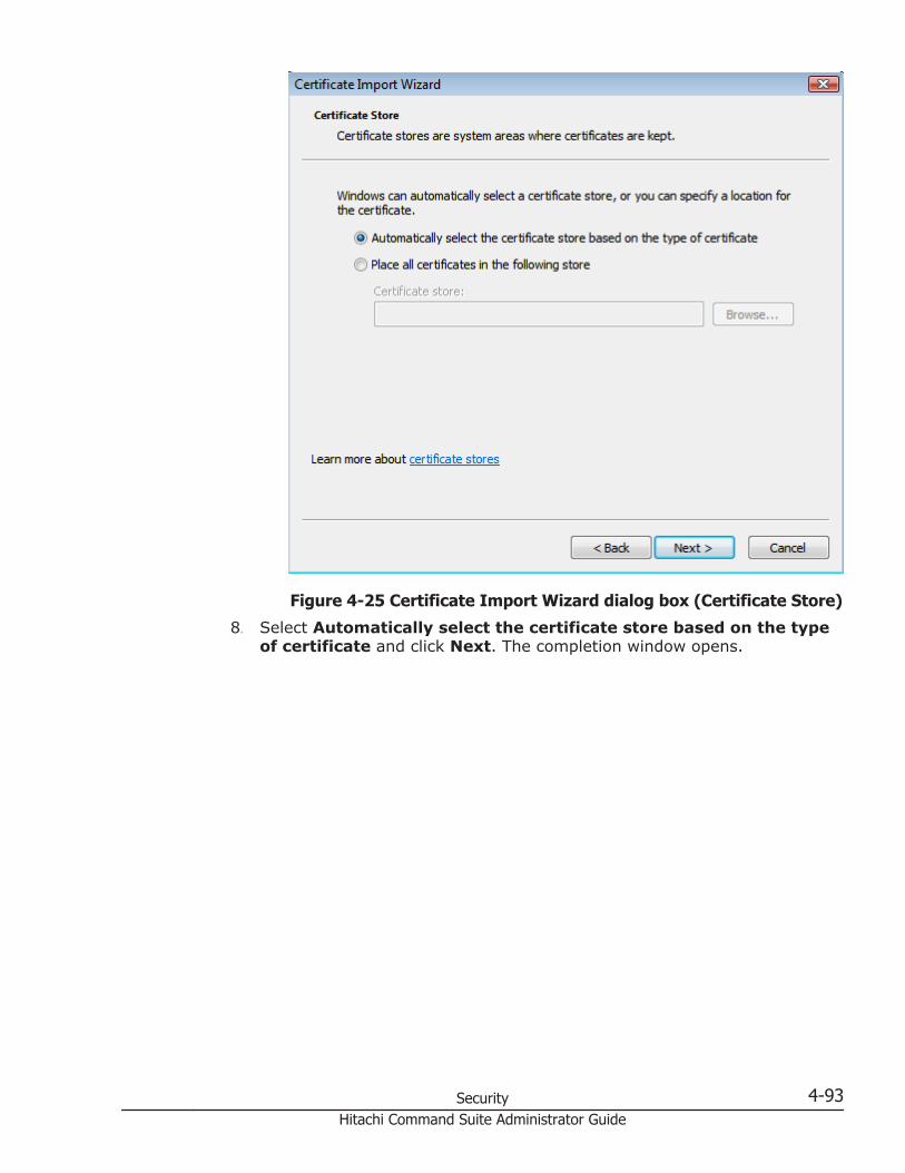
Figure 4-25 Certificate Import Wizard dialog box (Certificate Store)
8. Select Automatically select the certificate store based on the typeof certificate and click Next. The completion window opens.
Security 4-93Hitachi Command Suite Administrator Guide

Figure 4-26 Certificate Import Wizard dialog box (Completing theCertificate Import Wizard)
9. Click Finish. If the import was successful, the confirmation windowopens.
Figure 4-27 Certificate Import wizard dialog box
10. Click OK.
Related topics
• Normal login on page 5-26
4-94 SecurityHitachi Command Suite Administrator Guide

Blocking HTTP communication to the storage system
If the web server supports SSL (HTTPS), the HTTP setting tool allows you toblock access to port 80. This setting forces communication between the Webclient and SVP to use only port 443 (HTTPS).
If you are using Device Manager - Hitachi Command Suite to access DeviceManager - Storage Navigator, blocking HTTP communication might interferewith that access. Make sure the Hitachi Command Suite can use SSLcommunication to access Device Manager - Storage Navigator.
To block HTTP communication:
1. Close all Device Manager - Storage Navigator sessions on the SVP.2. Start the web browser.3. Specify the URL as follows:
https://IP-address-or-host-name-of-SVP/cgi-bin/utility/toolpanel.cgi
4. In the Tool Panel dialog box, click Set up HTTP Blocking.A login dialog box opens.
5. In the Login dialog box, Enter the storage administrator User ID andPassword, then click Login.The Set up HTTP Blocking dialog box opens.
6. In the dialog box, click OK.A confirmation dialog box opens.
7. In the confirmation dialog box, click OK to implement HTTP blocking.When the configuration change is complete, the SVP web server restarts.When the restart is complete, the HTTP Communications Blocked dialogbox opens.Depending on the environment, it can take 30 to 60 minutes for the webserver to restart. If it does, after the SVP restarts, the Completion dialogbox does not appear. Instead, an "internal server error" messageappears. However, the setting is actually completed.
Security 4-95Hitachi Command Suite Administrator Guide
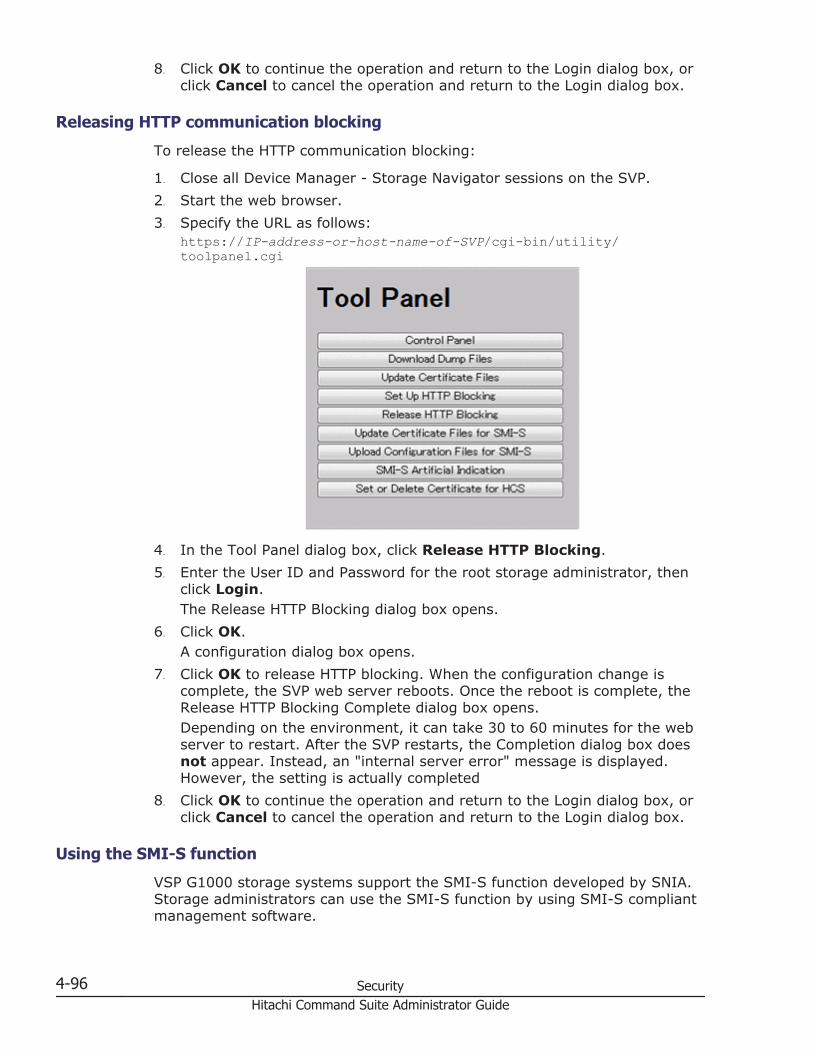
8. Click OK to continue the operation and return to the Login dialog box, orclick Cancel to cancel the operation and return to the Login dialog box.
Releasing HTTP communication blocking
To release the HTTP communication blocking:
1. Close all Device Manager - Storage Navigator sessions on the SVP.2. Start the web browser.3. Specify the URL as follows:
https://IP-address-or-host-name-of-SVP/cgi-bin/utility/toolpanel.cgi
4. In the Tool Panel dialog box, click Release HTTP Blocking.5. Enter the User ID and Password for the root storage administrator, then
click Login.The Release HTTP Blocking dialog box opens.
6. Click OK.A configuration dialog box opens.
7. Click OK to release HTTP blocking. When the configuration change iscomplete, the SVP web server reboots. Once the reboot is complete, theRelease HTTP Blocking Complete dialog box opens.Depending on the environment, it can take 30 to 60 minutes for the webserver to restart. After the SVP restarts, the Completion dialog box doesnot appear. Instead, an "internal server error" message is displayed.However, the setting is actually completed
8. Click OK to continue the operation and return to the Login dialog box, orclick Cancel to cancel the operation and return to the Login dialog box.
Using the SMI-S function
VSP G1000 storage systems support the SMI-S function developed by SNIA.Storage administrators can use the SMI-S function by using SMI-S compliantmanagement software.
4-96 SecurityHitachi Command Suite Administrator Guide

To use the SMI-S function, create a Device Manager - Storage Navigator useraccount and specify a storage system as the access destination from themanagement software.
Prerequisites
• SMI-S Provider software application must be installed.
Procedure
1. Create a Device Manager - Storage Navigator user account in themanagement software. The user account must belong to one of thefollowing built-in user groups:
¢ Storage Administrator (View & Modify) User Group. Users havefull permissions to access the SMI-S function from the managementsoftware.
¢ Storage Administrator (View Only) User Group. Users have read-only permissions to access the SMI-S function from the managementsoftware.
2. In the management software program, enter the following storage systeminformation:
¢ IP Address of the storage system¢ Protocol: specify HTTPS¢ Port: 5989¢ Namespace:root/hitachi/smis or interop
Troubleshooting
If you cannot access the SMI-S function, check the network environment andaccess destination.
Uploading a signed certificate to the SMI-S provider
To use certificates in SSL communication with the SMI-S provider, you mustupdate and upload the private key and the signed server certificate (publickey) to the SMI-S provider to update the certificate. Use the followingprocedure to upload and update certificates using a certificate update tool.
Prerequisites
Ensure that the following items have been completed:
• A private key (.key file) has been created. Change the file name toserver.key unless the file is already named that.
• A signed public key certificate (.crt file) has been acquired. Change thefile name to server.crt unless the file is already named that.
• The private key (server.key file) and the signed public key certificate(server.crt file) are in X509 PEM format.
Security 4-97Hitachi Command Suite Administrator Guide

Procedure
1. Close all Device Manager - Storage Navigator sessions on the SVP.2. Start the web browser.3. Specify the following URL to open the Tool Panel dialog box.
http://IP-address-or-host-name-of-SVP/cgi-bin/utility/toolpanel.cgi
4. In the Tool Panel dialog box, click Update Certificate Files for SMI-S.The login dialog box for Update Certificate Files for SMI-S opens.If SSL communication has been established, the Security Alert dialog boxopens before the login dialog box. In the Security Alert dialog box, clickOK.
5. In the login dialog box for Update Certificate Files for SMI-S, enter theadministrator's user ID and password, and click Login. The upload dialogbox for Update Certificate Files for SMI-S opens.
6. In the upload dialog box for Update Certificate Files for SMI-S, enter boththe public key certificate file name in the Certificate file (server.crt file)box and the Private Key file (server.key file) box. You can enter the filenames directly or by clicking Browse.
7. Click Upload. The execution confirmation dialog box for UpdateCertificate Files for SMI-S opens.
8. Click OK to update the certificate. Update of the certificate starts.Upon completion of the certificate update, the SMI-S provider restarts toreflect the update.Upon completion of the restart of the SMI-S provider, the updatecompletion dialog box for Update Certificate Files for SMI-S opens
9. In the update completion dialog box for Update Certificate Files for SMI-S,click OK. The display returns to the login dialog box.
Note: If an error occurs during update of the certificate, an error messagedisplays. Resolve the problem and then run the procedure again, starting withlogging in, to upload configuration files for SMI-S.
4-98 SecurityHitachi Command Suite Administrator Guide

Note: If the Security Alert dialog box for the certificate opens at other times,click View Certificate to confirm that the certificate is correct and then clickYes.
Returning an SMI-S provider certificate to default
You can return a certificate updated in Uploading a signed certificate to theSMI-S provider on page 4-97 to default.
To return a certificate to default:
1. Close all Device Manager - Storage Navigator sessions on the SVP.2. Start the web browser.3. Specify the following URL to open the Tool Panel dialog box.
http://IP-address-or-host-name-of-SVP/cgi-bin/utility/toolpanel.cgi
4. In the Tool Panel dialog box, click Upload Configuration Files for SMI-S. The Upload Configuration Files Login dialog box opens.If SSL communication has been established, the Security Alert dialog boxopens before the login dialog box. In the Security Alert dialog box, clickOK.
5. In the Login dialog box, enter the administrator's user ID and password,and click Login. The upload dialog box for Update Certificate Files forSMI-S opens.
6. In the upload dialog box for Update Certificate Files for SMI-S, clickReturn to the default configuration. The execution confirmation dialogbox for Update Certificate Files for SMI-S opens.
7. Click OK to update the certificate. Update of the certificate starts.Upon completion of the certificate update, the SMI-S provider restarts toreflect the update. Upon completion of the restart of the SMI-S provider,the update completion dialog box for Update Certificate Files for SMI-Sopens.
Security 4-99Hitachi Command Suite Administrator Guide
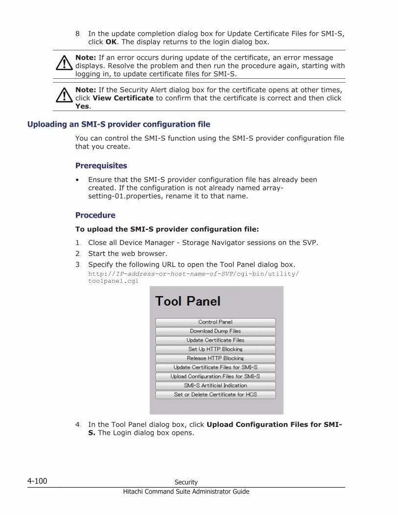
8. In the update completion dialog box for Update Certificate Files for SMI-S,click OK. The display returns to the login dialog box.
Note: If an error occurs during update of the certificate, an error messagedisplays. Resolve the problem and then run the procedure again, starting withlogging in, to update certificate files for SMI-S.
Note: If the Security Alert dialog box for the certificate opens at other times,click View Certificate to confirm that the certificate is correct and then clickYes.
Uploading an SMI-S provider configuration file
You can control the SMI-S function using the SMI-S provider configuration filethat you create.
Prerequisites
• Ensure that the SMI-S provider configuration file has already beencreated. If the configuration is not already named array-setting-01.properties, rename it to that name.
Procedure
To upload the SMI-S provider configuration file:
1. Close all Device Manager - Storage Navigator sessions on the SVP.2. Start the web browser.3. Specify the following URL to open the Tool Panel dialog box.
http://IP-address-or-host-name-of-SVP/cgi-bin/utility/toolpanel.cgi
4. In the Tool Panel dialog box, click Upload Configuration Files for SMI-S. The Login dialog box opens.
4-100 SecurityHitachi Command Suite Administrator Guide

If SSL communication has been established, the Security Alert dialog boxopens before the Login dialog box. In the Security Alert dialog box, clickOK to confirm and open the Login dialog box.
5. In the Login dialog box, enter the administrator user ID and password,and click Login. The Upload dialog box opens.
6. In the Upload dialog box, enter the SMI-S provider configuration file(array-setting-01.properties).Enter a file name in Configuration file or click Browse and then select afile in the displayed dialog box.
7. Click Upload. The execution confirmation dialog box opens.8. Click OK to update the configuration file. Update of the configuration file
starts.Upon completion of the configuration file update, the SMI-S providerrestarts to reflect the update.Upon completion of the restart of the SMI-Sprovider, the update completion dialog box for Upload Configuration Filesfor SMI-S opens.
9. In the Upload Configuration Files for SMI-S dialog box, click OK. Thedisplay returns to the login dialog box.
Note: If an error occurs during update of the certificate, an error messagedisplays. Resolve the problem and then run the procedure again, starting withlogging in, to upload configuration files for SMI-S.
Note: If the Security Alert dialog box for the certificate opens at other times,click View Certificate to confirm that the certificate is correct and then clickYes.
Returning an SMI-S provider configuration file to default
You can return the configuration file updated in Uploading an SMI-S providerconfiguration file on page 4-100.
To return the configuration file to default:
1. Close all Device Manager - Storage Navigator sessions on the SVP.2. Start the web browser.3. Specify the following URL to open the Tool Panel dialog box.
http://IP-address-or-host-name-of-SVP/cgi-bin/utility/toolpanel.cgi
Security 4-101Hitachi Command Suite Administrator Guide

4. In the Tool Panel dialog box, click Upload Configuration Files for SMI-S. The Login dialog box opens.If SSL communication has been established, the Security Alert dialog boxopens before the Login dialog box. In the Security Alert dialog box, clickOK to confirm and open the Login dialog box.
5. In the Login dialog box, enter the administrator user ID and password,and click Login. The Upload dialog box opens.
6. In the Upload dialog box, click Return to the default configuration. Aconfirmation dialog box opens.
7. In the confirmation dialog box, Click OK to update the configuration file.The update process starts.When the file has been updated, the SMI-S provider restarts to includethe update. When the SMI-S provider restarts, the update completiondialog box opens.
8. In the update completion dialog box, click OK to confirm and return tothe Login dialog box.
Note: If an error occurs during update of the SMI-S provider configurationfile, an error message appears. Resolve the problem described in the errormessage and then run the procedure again, starting with Step 5.
Note: If the Security Alert dialog box for the certificate opens at other times,click View Certificate to confirm that the certificate is correct and then clickYes.
Sending SMI-S Artificial Indication
You can send an SMI-S artificial indication to determine whether thecommunication between the listeners and the SMI-S provider succeeds orfails.
Prerequisites
• SMI-S Provider software application must be installed.
4-102 SecurityHitachi Command Suite Administrator Guide

• The network environment is configured so that the computer on which thelistener application operates is connected to the SVP.
• The listeners are subscribed to the SMI-S provider.
Procedure
To send an SMI-S artificial indication:
1. Close all Device Manager - Storage Navigator sessions connected to therelated SMI-S provider.
2. On the Device Manager - Storage Navigator computer, open a webbrowser and enter the following URL to open the Tool Panel dialog box.http://IP-address-or-host-name-of-SVP/cgi-bin/utility/toolpanel.cgi
3. In the Tool Panel dialog box, click SMI-S Artificial Indication. TheSMI-S Artificial Indication dialog box opens.
4. In the SMI-S Artificial Indication dialog box, enter the user ID andpassword, and click Test. The testing begins.
5. When the test communication is completed, SMI-S Artificial IndicationResult window opens.In the SMI-S Artificial Indication Result window, click OK. The dialogbox closes and the display returns to the SMI-S Artificial Indicationdialog box.
Note: If the SMI-S artificial indication fails, an error message and a codedisplay. Resolve the problem described in the error message.
Array-setting-01.properties file
This section describes the description format and organization format of SMI-S provider user configuration files and parameters to be defined. The array-setting-01.properties file is an SMI-S provider user configuration file.
Security 4-103Hitachi Command Suite Administrator Guide

File description format
The format of the array-setting-01.properties file includes the followingitems:
• File format: text• Character code: ISO 8859-1• Line-end symbol: \n, \r, or \r\n• Comment: Line on which # or ! is the first non-space character
File organization format
The organization of the array-setting-01.properties file is shown here:
# comment line
parameter1= parameter1_setting_value
parameter2= parameter2_setting_value
# comment line
Parameters defined in user configuration files
Table 4-2 Parameters defined in user configuration files
Parameter name Description
VVolForSnapshot Use the VVolForSnapshot parameter to specify virtual volumesthat the SMI-S provider can use when you operate Thin Imagefrom CreateElementReplica of HITACHI_ReplicationService.Optional item. If no value is specified, the default value applies.If you specify this item, be sure to specify PoolIDForSnapshot aswell.All virtual volumes are specified by default.Setting up the VVolForSnapshot parameter
Set up the parameter by using <RangeOfVVol> and<SingleVVol> with a comma (,) as a delimiter:- <RangeOfVVol>: Specifies a range of virtual volumes- <SingleVVol>: Specifies a single virtual volume
<RangeOfVVol> format<S2HexLDKC>:<S2HexCU>:<S2HexLDEV>to<E2HexLDKC>:<E2HexCU>:<E2HexLDEV>- <S2HexLDKC>: LDKC number (two-digit hexadecimal) ofthe first virtual volume in the specified range- <S2HexCU>: CU number (two-digit hexadecimal) of thefirst virtual volume in the specified range- <S2HexLDEV>: LDEV number (two-digit hexadecimal) ofthe first virtual volume in the specified range- <E2HexLDKC>: LDKC number (two-digit hexadecimal) ofthe last virtual volume in the specified range
4-104 SecurityHitachi Command Suite Administrator Guide

Parameter name Description
- <E2HexCU>: CU number (two-digit hexadecimal) of thelast virtual volume in the specified range- <E2HexLDEV>: LDEV number (two-digit hexadecimal) ofthe last virtual volume in the specified range
<SingleVVol> format<2HexLDKC>:<2HexCU>:<2HexLDEV>- <2HexLDKC>: LDKC number (two-digit hexadecimal) ofthe single virtual volume to be specified- <2HexCU>: CU number (two-digit hexadecimal) of thesingle virtual volume to be specified- <2HexLDEV>: LDEV number (two-digit hexadecimal) ofthe single virtual volume to be specified
ExampleVVolForSnapshot=00:00:00to00:00:FF,00:02:00,00:04:00to00:04:FFIn this example, a virtual volume having one of thefollowing LDEV IDs is used as the snapshot target:- From 00:00:00 (LDKC=0,CU=0,LDEV=0) to 00:00:FF(LDKC=0,CU=0,LDEV=255)- 00:02:00 (LDKC=0,CU=2,LDEV=0)- From 00:04:00 (LDKC=0,CU=4,LDEV=0) to 00:04:FF(LDKC=0,CU=4,LDEV=255)
PoolIDForSnapshot Use the PoolIDForSnapshot parameter to specify pools that theSMI-S provider can use when you run Thin Image fromCreateElementReplica of HITACHI_ReplicationService.Specifies pools that can be used by the SMI-S provider.Optional item. If no value is specified, the default value applies.If you specify this item, be sure to specify VVolForSnapshot aswell.All pools are specified by default.Setting up the PoolIDForSnapshot parameter
Set up the parameter by using <RangeOfPoolID> and<SinglePoolID> with a comma (,) as a delimiter:- <RangeOfPoolID>: Specifies a range of pool IDs- <SinglePoolID>: Specifies a single pool ID
<RangeOfPoolID> format<Start PoolID>to<End PoolID>- <Start PoolID>: ID of the first pool in the specified range- <End PoolID>: ID of the last pool in the specified range
<SinglePoolID> format<PoolID>- <PoolID>: ID of the pool to be specified
ExamplePoolIDForSnapshot=1to2,4,6to8In this example, pools having one of the following pool IDsare used as snapshot pools:
Security 4-105Hitachi Command Suite Administrator Guide

Parameter name Description
- 1 to 2- 4- 6 to 8
Registering certificates for HCS
To check the server reliability at the time of SSL communication for HCSexternal authentication, upload an HCS public key certificate to the webserver to register the certificate. Complete the steps in the followingprocedure to upload and register a certificate using the certificate updatetool.
Prerequisites
• You must have Security Administrator (View & Modify) role to performthis task.
• If the certificate to be registered has an extension other than ".crt",change it to ".crt".
• The certificate to be registered must be in X509 format.
To register certificates for HCS:
1. Close all Device Manager - Storage Navigator sessions on the SVP.2. On the Device Manager - Storage Navigator computer, open a web
browser and enter the following URL to open the Tool Panel dialog box.http://IP-address-or-host-name-of-SVP/cgi-bin/utility/toolpanel.cgi
3. In the Tool Panel dialog box, click Set or Delete Certificate File forHCS. The Login dialog box opens.If SSL communication has been established, the Security Alert dialog boxopens before the Login dialog box. In the Security Alert dialog box, clickOK.
4-106 SecurityHitachi Command Suite Administrator Guide

4. When the Login dialog box opens, enter the administrator user ID andpassword, and click Login. The Login dialog box opens.
5. In the dialog box, enter the certificate file for HCS (.crt file) in theCertificate file (.crt file) box. You can enter the file name directly or byclicking Browse and searching for the file name.
6. Click Register. The execution confirmation dialog for Set or DeleteCertificate File for HCS opens.
7. Click OK to register the certificate. Registration of the certificate starts.When the certificate is registered, the registration completion dialog boxfor Set or Delete Certificate File for HCS opens.
8. In the registration completion dialog box for Set or Delete CertificateFile for HCS, click OK. The display returns to the login dialog box.
Note: If an error occurs during registration of the HCS certificate, an errormessage displays. Resolve the problem and then run the procedure again,starting with logging in, to Set or Delete HCS Certificate.
Note: If the Security Alert dialog box for the certificate opens at other times,click View Certificate to confirm that the certificate is correct and then clickYes.
Related Topics
• Deleting certificates for HCS on page 4-107.
Notes on registering certificates for HCS
Read the following notes about registering certificates for HCS:
• Ensure that the certificate to be registered is the right one. If you registera wrong certificate, HCS external authentication is not performed.
• Only with registration or deletion of the correct certificate, HCS externalauthentication operates normally
Deleting certificates for HCS
You can delete the certificates you registered in the procedure of the"Registering certificates for HCS" section. Once you delete a certificate,server, reliability for that certificate is not checked by SSL communication forHCS external authentication.
Prerequisites
• You must have Security Administrator (View & Modify) role to performthis task.
To delete certificates for HCS:
1. Close all Device Manager - Storage Navigator sessions on the SVP.2. On the Device Manager - Storage Navigator computer, open a web
browser and enter the following URL to open the Tool Panel dialog box.
Security 4-107Hitachi Command Suite Administrator Guide

http://IP-address-or-host-name-of-SVP/cgi-bin/utility/toolpanel.cgi
3. In the Tool Panel dialog box, click Set or Delete Certificate File forHCS. The login dialog box opens.If SSL communication has been established, the Security Alert dialog boxopens before the login dialog box. In the Security Alert dialog box, clickOK.
4. In the login dialog box, enter the administrator user ID and password,and click Login. The Set or Delete Certificate File for HCS dialog boxopens.
5. In the dialog box, click Delete. A confirmation dialog box opens.6. Click OK to delete the certificate. Deletion of the certificate starts.When
the certificate has been deleted, a completion dialog box opens.7. In the completion dialog box click OK. The display returns to the login
dialog box.
Note: If an error occurs during deletion of the certificate for HCS, an errormessage displays. Resolve the problem and then run the procedure again,starting with logging in, to Set or Delete Certificate for HCS.
Note: If the Security Alert dialog box for the certificate opens at other times,click View Certificate to confirm that the certificate is correct and then clickYes.
Configuring an SSL server and clients (CIM server)To use SSL server authentication for object operations, you need to create aserver certificate in the Device Manager server, and then import it into theCIM client. To use two-way authentication, you need to create a clientcertificate in the CIM client and then import it into the Device Managerserver.
To use SSL server authentication for event indications, you need to create aserver certificate in the CIM client, and then import it into the Device
4-108 SecurityHitachi Command Suite Administrator Guide

Manager server. To use two-way authentication, you need to create a clientcertificate in the Device Manager server and then import it into the CIMclient.
Creating a keystore file for object operations
To create a keystore file for object operations, use the hcmds64keytool utility(for Windows) or the keytool utility (for Linux).
Operations to complete in advance
• Delete the existing keystore file for object operations.
In Windows:installation-folder-for-Hitachi-Command-Suite\DeviceManager\HiCommandServer\wsi\server\jserver\bin\.keystore
In Linux:installation-directory-for-Hitachi-Command-Suite/HiCommandServer/wsi/server/jserver/bin/.keystore
To create a keystore file for object operations:
1. Execute the following command to create a keystore file for objectoperations.
In Windows:installation-folder-for-Hitachi-Command-Suite\Base64\bin\hcmds64keytool -genkey -keystore keystore-file-name -storepass keystore-password -alias alias -dname entity-distinguished-name -validity validity-of-certificate -keypass private-key-password -keyalg key-algorithm -sigalgsignature-algorithm -keysize key-size
In Linux:installation-directory-for-Hitachi-Command-Suite/Base64/uCPSB/jdk/bin/keytool -genkey -keystore keystore-file-name -storepass keystore-password -alias alias -dname entity-distinguished-name -validity validity-of-certificate -keypass private-key-password -keyalg key-algorithm -sigalgsignature-algorithm -keysize key-size
¢ keystore: Specify the keystore file for object operations(.keystore) .
¢ storepass and keypass: Specify the same password.2. Execute WSIEncryptString.jar to encrypt the keystore password.
WSIEncryptString.jar is stored at the following paths.
In Windows:installation-folder-for-Hitachi-Command-Suite\DeviceManager\HiCommandServer\wsi\server\jserver\lib\
Security 4-109Hitachi Command Suite Administrator Guide

In Linux:installation-directory-for-Hitachi-Command-Suite/HiCommandServer/wsi/server/jserver/lib/
> java -jar WSIEncryptString.jar keystore-password
The encrypted keystore password is displayed. You will need to specify thisstring in the MOF file for object operations.
Editing an MOF file for object operations
Set the keystore password encrypted by WSIEncryptString.jar in the MOFfile for object operations, and then compile the file.
Operations to complete in advance
Create a keystore file for object operations.
Information to collect in advance
Keystore password encrypted by WSIEncryptString.jar.
To edit an MOF file for object operations:
1. Stop the Hitachi Command Suite product services.2. Set the keystore password encrypted by WSIEncryptString.jar in the
MOF file for object operations(CIMXMLSCOMATLSSettingData_instances.mof).The MOF file is stored in the following locations.
In Windows:installation-folder-for-Hitachi-Command-Suite\DeviceManager\HiCommandServer\wsi\server\jserver\mof\wbemserver
In Linux:installation-directory-for-Hitachi-Command-Suite/HiCommandServer/wsi/server/jserver/mof/wbemserver
Replace XXXXXX in KeyStorePassword with the encrypted keystorepassword.
instance of HITACHI_CIMXMLSCOMATLSSettingData { InstanceID = HITACHI:HITACHI_CIMXMLSCOMATLSSettingData:001"; ElementName = "CIM-XML Client Adapter TLS Settings"; MutualAuthenticationRequired = false; KeyStoreFile = "{0}/jserver/bin/.keystore"; KeyStorePassword = "XXXXXX"; TrustStoreFile = "{0}/jserver/bin/.truststore";};
3. Execute the mofcomp command to compile the MOF file for objectoperations.
4-110 SecurityHitachi Command Suite Administrator Guide

In Windows:installation-folder-for-Hitachi-Command-Suite\DeviceManager\HiCommandServer\wsi\bin\mofcomp.bat
In Linux:installation-directory-for-Hitachi-Command-Suite/HiCommandServer/wsi/bin/mofcomp
mofcomp -m -o ..\server\jserver\logr ..\server\jserver\mof\wbemserver\CIMXMLSIndicationHandlerTLSSettingData_instances.mof
4. Start the Hitachi Command Suite product services.
Related topics
• Starting the Hitachi Command Suite services on page 8-4• Stopping the Hitachi Command Suite services on page 8-5
Exporting a server certificate for object operations
To export a Device Manager server certificate for object operations from thekeystore file (.keystore), select SSL configuration for SMI-S, and thenExport Server's Certificate from KeyStore for Object Operations fromthe HiKeytool main menu.
Operations to complete in advance
Edit the MOF file for object operations.
Information to collect in advance
• Keystore password for object operations• Alias name of the server certificate for object operations
To export a server certificate for object operations:
1. Execute the following to start HiKeytool.
In Windows:installation-folder-for-Hitachi-Command-Suite\DeviceManager\HiCommandServer\HiKeytool.bat
In Linux:installation-directory-for-Hitachi-Command-Suite/HiCommandServer/HiKeytool.sh
2. In the main menu, enter 2 (SSL configuration for SMI-S).3. In the SMI-S main menu, enter 5 (Export Server's Certificate from
KeyStore for Object Operations) .4. Specify the keystore password, alias name, and output destinations for
the server certificate for object operations.
Security 4-111Hitachi Command Suite Administrator Guide

Enter keystore-password:serversslEnter alias:foocorpserverEnter authentication-filename(absolute path):c:\tmp\server.cer
Enabling two-way authentication for object operations
To enable two-way authentication for object operations, select SSLconfiguration for SMI-S, and then Set Security Level for ObjectOperations from the HiKeytool main menu.
To enable two-way authentication for object operations:
1. Stop the Hitachi Command Suite product services.2. Execute the following to start HiKeytool.
In Windows:installation-folder-for-Hitachi-Command-Suite\DeviceManager\HiCommandServer\HiKeytool.bat
In Linux:installation-directory-for-Hitachi-Command-Suite/HiCommandServer/HiKeytool.sh
3. In the main menu, enter 2 (SSL configuration for SMI-S).4. In the SMI-S main menu, enter 1 (Set Security Level for Object
Operations) .5. Enter 2 (SSL with two-way authentication) .
The MOF file for object operations will be compiled and the SMI-S mainmenu will appear again.
6. Start the Hitachi Command Suite product services.
You must stop the Device Manager Server before specifying this setting.1) SSL without two-way authentication2) SSL with two-way authentication >2
Note: If the message The compilation of the MOF file failed. appears,collect all the files in the following location, and then contact maintenancepersonnel.In Windows:installation-folder-for-Hitachi-Command-Suite\DeviceManager\HiCommandServer\wsi\server\jserver\mof\wbemserverIn Linux:installation-directory-for-Hitachi-Command-Suite/HiCommandServer/wsi/server/jserver/mof/wbemserver
Related topics
• Starting the Hitachi Command Suite services on page 8-4
4-112 SecurityHitachi Command Suite Administrator Guide

• Stopping the Hitachi Command Suite services on page 8-5
Importing a client certificate for object operations
To import a CIM client certificate for object operations in two-wayauthentication into the truststore file (.truststore), select SSLconfiguration for SMI-S, and then Import Client's Certificate toTrustStore for Object Operations from the HiKeytool main menu.
Operations to complete in advance
• Obtain the client certificate for object operations from a CIM client (seeExporting a server or client certificate for a CIM client on page 4-121).
• Delete the existing truststore file for object operations (.truststore).(see Truststores on page 4-30)
To import a client certificate for object operations:
1. Execute the following to start HiKeytool.
In Windows:installation-folder-for-Hitachi-Command-Suite\DeviceManager\HiCommandServer\HiKeytool.bat
In Linux:installation-directory-for-Hitachi-Command-Suite/HiCommandServer/HiKeytool.sh
2. In the main menu, enter 2 (SSL configuration for SMI-S).3. In the SMI-S main menu, enter 3 (Import Client's Certificate to
TrustStore for Object Operations) .4. Specify the alias name, truststore password, and absolute path of the
client certificate for object operations.
Enter alias:foocorpclientEnter truststore-password:trustsslEnter authentication-filename(absolute path):c:\tmp\client.cer
Creating a keystore file for event indications
To create a keystore file for event indications, use the hcmds64keytool utility(for Windows) or the keytool utility (for Linux).
Operations to complete in advance
• Delete the existing keystore file for event indications if you want to re-create the file.
In Windows:installation-folder-for-Hitachi-Command-Suite\DeviceManager\HiCommandServer\wsi\server\jserver\bin\indkeystore
Security 4-113Hitachi Command Suite Administrator Guide

In Linux:installation-directory-for-Hitachi-Command-Suite/HiCommandServer/wsi/server/jserver/bin/indkeystore
To create a keystore file for event indications:
1. Execute the following command to create a keystore file for eventindications:
In Windows:installation-folder-for-Hitachi-Command-Suite\Base64\bin\hcmds64keytool -genkey -keystore keystore-file-name -storepass keystore-password -alias alias -dname entity-distinguished-name -validity validity-of-certificate -keypass private-key-password -keyalg key-algorithm -sigalgsignature-algorithm -keysize key-size
In Linux:installation-directory-for-Hitachi-Command-Suite/Base64/uCPSB/jdk/bin/keytool -genkey -keystore keystore-file-name -storepass keystore-password -alias alias -dname entity-distinguished-name -validity validity-of-certificate -keypass private-key-password -keyalg key-algorithm -sigalgsignature-algorithm -keysize key-size
¢ keystore: Specify the keystore file for event indications(indkeystore).
¢ storepass and keypass: Specify the same password.2. Execute WSIEncryptString.jar to encrypt the keystore password.
WSIEncryptString.jar is stored at the following paths.
In Windows:installation-folder-for-Hitachi-Command-Suite\DeviceManager\HiCommandServer\wsi\server\jserver\lib\
In Linux:installation-directory-for-Hitachi-Command-Suite/HiCommandServer/wsi/server/jserver/lib/
> java -jar WSIEncryptString.jar keystore-password
An encrypted keystore password is displayed. Specify this string in the MOFfile for event indications.
Editing an MOF file for event indications
Specify a keystore password encrypted by WSIEncryptString.jar in the MOFfile for event indications, and then compile the file.
4-114 SecurityHitachi Command Suite Administrator Guide

Operations to complete in advance
Create a keystore file for event indications.
To edit an MOF file for event indications:
1. Stop the Hitachi Command Suite product services.2. Set the keystore password encrypted by WSIEncryptString.jar in the
MOF file for event indications(CIMXMLSIndicationHandlerTLSSettingData_instances.mof), and thenchange the MutualAuthenticationRequired value to true.The MOF file is stored in the following locations:
In Windows:installation-folder-for-Hitachi-Command-Suite\DeviceManager\HiCommandServer\wsi\server\jserver\mof\wbemserver
In Linux:installation-directory-for-Hitachi-Command-Suite/HiCommandServer/wsi/server/jserver/mof/wbemserver
Replace xxxxxxx in KeyStorePassword with the encrypted keystorepassword.
instance of HITACHI_CIMXMLSIndicationHandlerTLSSettingData {
InstanceID = "HITACHI:HITACHI_CIMXMLSIndicationHandlerTLSSettingData:001"; ElementName = "CIM_XML-TLS Indication Handler Settings"; MutualAuthenticationRequired = true; KeyStoreFile = "{0}/jserver/bin/indkeystore"; KeyStorePassword = "xxxxxxx"; TrustStoreFile = "{0}/jserver/bin/indtruststore";};
3. Execute the mofcomp command to compile the MOF file for eventindications.
In Windows:installation-folder-for-Hitachi-Command-Suite\DeviceManager\HiCommandServer\wsi\bin\mofcomp.bat
In Linux:installation-directory-for-Hitachi-Command-Suite/HiCommandServer/wsi/bin/mofcomp
mofcomp -m -o ..\server\jserver\logr ..\server\jserver\mof\wbemserver\CIMXMLSCOMATLSSettingData_instances.mof
4. Start the Hitachi Command Suite product services.
Related topics
• Starting the Hitachi Command Suite services on page 8-4• Stopping the Hitachi Command Suite services on page 8-5
Security 4-115Hitachi Command Suite Administrator Guide

Exporting a client certificate for event indications
To export a client certificate for event indications in two-way authenticationfrom the keystore (indkeystore) file, select SSL configuration for SMI-S,and thenExport Server's Certificate from KeyStore for EventIndications from the HiKeytool main menu.
Operations to complete in advance
Edit the MOF file for event indications.
Information to collect in advance
• Keystore password for event indications• Alias name of the client certificate for event indications
To export a client certificate for event indications:
1. Execute the following to start HiKeytool.
In Windows:installation-folder-for-Hitachi-Command-Suite\DeviceManager\HiCommandServer\HiKeytool.bat
In Linux:installation-directory-for-Hitachi-Command-Suite/HiCommandServer/HiKeytool.sh
2. In the main menu, enter 2 (SSL configuration for SMI-S).3. In the SMI-S main menu, enter 6 (Export Server's Certificate from
KeyStore for Event Indications) .4. Specify the keystore password, alias name, and output destinations for
the client certificate for event indications.
Enter keystore-password:serverindtrustEnter alias:foocorpindserverEnter authentication-filename(absolute path):c:\tmp\serverind.cer
Enabling two-way authentication for event indications
To enable two-way authentication for event indications, select SSLconfiguration for SMI-S, and then Set Security Level for EventIndications from the HiKeytool main menu.
To enable two-way authentication for event indications:
1. Stop the Hitachi Command Suite product services.2. Execute the following to start HiKeytool.
In Windows:installation-folder-for-Hitachi-Command-Suite\DeviceManager\HiCommandServer\HiKeytool.bat
4-116 SecurityHitachi Command Suite Administrator Guide

In Linux:installation-directory-for-Hitachi-Command-Suite/HiCommandServer/HiKeytool.sh
3. In the main menu, enter 2 (SSL configuration for SMI-S).4. In the SMI-S main menu, enter 2 (Set Security Level for Event
Indications) .5. Enter 2 (SSL with two-way authentication) .
The MOF file for event indications will be compiled, and the SMI-S mainmenu will appear again.
6. Start the Hitachi Command Suite product services.
You must stop the Device Manager Server before specifying this setting.1) SSL without two-way authentication2) SSL with two-way authentication >2
Note: If the message The compilation of the MOF file failed. appears,collect all the files at the following location, and then contact maintenancepersonnel.In Windows:installation-folder-for-Hitachi-Command-Suite\DeviceManager\HiCommandServer\wsi\server\jserver\mof\In Linux:installation-directory-for-Hitachi-Command-Suite/HiCommandServer/wsi/server/jserver/mof/
Related topics
• Starting the Hitachi Command Suite services on page 8-4• Stopping the Hitachi Command Suite services on page 8-5
Importing a server certificate for event indications
To import a server certificate for event indications of a CIM client into thetruststore file (indtruststore), select SSL configuration for SMI-S, andthen Import Client's Certificate to TrustStore for Event Indicationsfrom the HiKeytool main menu.
Operations to complete in advance
• Obtain a CIM client server certificate for event indications (see Exportinga server or client certificate for a CIM client on page 4-121).
• Delete the existing truststore file for event indications (indtruststore).(see Truststores on page 4-30)
Security 4-117Hitachi Command Suite Administrator Guide

To import a server certificate for event indications:
1. Execute the following to start HiKeytool.
In Windows:installation-folder-for-Hitachi-Command-Suite\DeviceManager\HiCommandServer\HiKeytool.bat
In Linux:installation-directory-for-Hitachi-Command-Suite/HiCommandServer/HiKeytool.sh
2. In the main menu, enter 2 (SSL configuration for SMI-S).3. In the SMI-S main menu, enter 4 (Import Client's Certificate into
TrustStore for Event Indications) .4. Specify the alias name, truststore password, and absolute path of the CIM
client server certificate.
Enter alias:foocorpindclientEnter truststore-password:indtrustEnter authentication-filename(absolute path):c:\tmp\clientind.cer
Checking a self-signed certificate for a CIM server
To check a Device Manager server (CIM server) self-signed certificate forobject operations or event indications, use the hcmds64keytool utility (forWindows) or the keytool utility (for Linux).
Information to collect in advance
• Keystore password
To check a self-signed certificate for a CIM server:
1. Execute the following command:
In Windows:installation-folder-for-Hitachi-Command-Suite\Base64\bin\hcmds64keytool -list -keystore keystore-file-name -storepasskeystore-password
In Linux:installation-directory-for-Hitachi-Command-Suite/Base64/uCPSB/jdk/bin/keytool -list -keystore keystore-file-name -storepass keystore-password
¢ keystore: Specify the keystore file you want to check.¢ storepass: Specify the keystore password.
4-118 SecurityHitachi Command Suite Administrator Guide

Self-signed certificate for object operations supplied with the product
The self-signed certificate for object operations that comes with DeviceManager uses the SHA256withRSA algorithm and has a key size of 2,048 bits.
The self-signed certificate is stored in the following keystore file (whosepassword is wbemssl):
In Windows:installation-folder-for-Hitachi-Command-Suite\DeviceManager\HiCommandServer\wsi\server\jserver\bin\.keystore
In Linux:installation-directory-for-Hitachi-Command-Suite/HiCommandServer/wsi/server/jserver/bin/.keystore
Disabling two-way authentication
Use HiKeytool to disable two-way authentication for object operations orevent indications.
To disable two-way authentication:
1. Stop the Hitachi Command Suite product services.2. Execute the following to start HiKeytool.
In Windows:installation-folder-for-Hitachi-Command-Suite\DeviceManager\HiCommandServer\HiKeytool.bat
In Linux:installation-directory-for-Hitachi-Command-Suite/HiCommandServer/HiKeytool.sh
3. In the main menu, enter 2 (SSL configuration for SMI-S).4. In the SMI-S main menu, enter 1 (Set Security Level for Object
Operations) or 2 (Set Security Level for Event Indications) .5. Enter 1 (SSL without two-way authentication)
The MOF file will be compiled and the SMI-S main menu will appear again.6. Start the Hitachi Command Suite product services.
You must stop the Device Manager Server before specifying this setting.1) SSL without two-way authentication2) SSL with two-way authentication >1
Note: If the message The compilation of the MOF file failed. appears,collect all the files at the following location, and then contact maintenancepersonnel:In Windows:
Security 4-119Hitachi Command Suite Administrator Guide

installation-folder-for-Hitachi-Command-Suite\DeviceManager\HiCommandServer\wsi\server\jserver\mof\In Linux:installation-directory-for-Hitachi-Command-Suite/HiCommandServer/wsi/server/jserver/mof/
Related topics
• Starting the Hitachi Command Suite services on page 8-4• Stopping the Hitachi Command Suite services on page 8-5
Configuring an SSL server and clients (CIM client)To use SSL server authentication for object operations, you need to create aserver certificate in the Device Manager server, and then import it into theCIM client. To use two-way authentication, you need to create a clientcertificate in the CIM client, and then import into the Device Manager server.
To use SSL server authentication for event indications, you need to create aserver certificate in the CIM client, and then import it into the DeviceManager server. To use two-way authentication, you need to create a clientcertificate in the Device Manager server, and then import it into the CIMclient.
Creating a key pair and self-signed certificate for a CIM client
To create a key pair and self-signed certificate from a CIM client, use thekeytool utility.
Operations to complete in advance
Install Java onto a CIM client.
To create a key pair and self-signed certificate for a CIM client:
1. Execute the following command to create a key pair and self-certificate:keytool -genkey -keystore keystore-file-name -storepasskeystore-password -alias alias -dname entity-distinguished-name-validity validity-of-certificate -keypass private-key-password-keyalg key-algorithm -sigalg signature-algorithm -keysize key-size
¢ Do not use the following symbols in the file name:: , ; * ? " < > |
¢ Specify the file name as a character string of no more than 255 bytes.¢ Do not include double quotation marks (") in the alias or password.¢ For the storepass option and the keypass option, specify the same
password.2. Execute the following command to check the contents of the created key
pair and self-signed certificate:
4-120 SecurityHitachi Command Suite Administrator Guide

keytool -list -keystore keystore-file-name -storepass keystore-password
Exporting a server or client certificate for a CIM client
Use the keytool utility to export a server or client certificate for a CIM clientfrom the client's keystore file.
Operations to complete in advance
• Install Java onto the CIM client.• Create a CIM client server certificate.
Information to collect in advance
• Path of the keystore file in the CIM client• Alias name for the server certificate in the CIM client• Keystore password in the CIM client
To export a server or client certificate for a CIM client:
1. Execute the following command to export the server or client certificatefor a CIM client:keytool -export -keystore keystore-file-name -storepasskeystore-password -alias alias -file certificate-file-name
2. Execute the following command to check the contents of the exportedserver or client certificate:keytool -printcert -v -file certificate-file-name
Importing a server or client certificate into a CIM client
Use the keytool utility to import a server or client certificate for the DeviceManager into a CIM client truststore.
Operations to complete in advance
• Install Java onto the CIM client.• Obtain a Device Manager server certificate (see Exporting a server
certificate for object operations on page 4-111, Exporting a clientcertificate for event indications on page 4-116).
Information to collect in advance
• CIM client truststore password
To import a server or client certificate into a CIM client:
1. Execute the following command to import a server or client certificate forthe Device Manager:
Security 4-121Hitachi Command Suite Administrator Guide

keytool -import -alias alias -keystore truststore-file-name -storepass truststore-password -trustcacerts -file certificate-file-name
¢ Do not use the following symbols in the file name:: , ; * ? " < > |
¢ Specify the file name as a character string of no more than 255 bytes.2. Execute the following command to check the contents of the truststore
file:keytool -list -keystore truststore-file-name -storepasstruststore-password
Controlling management client access to the managementserver
In Hitachi Command Suite products, you can control which managementclients can access the management server through the GUI or CLI. To restrictthe management clients that can access the management server, edit theuser_httpsd.conf file and the properties file for the Device Manager server.
Information to collect in advance
• Information about the management clients that can access themanagement serverUse either of the following formats to specify the management clients thatcan access the management server:
¢ The domain name (example: hitachi.datasystem.com)¢ Part of the domain name (example: hitachi)¢ The IPv4 or IPv6 address (example: 10.1.2.3 127.0.0.1
2001::123:4567:89ab:cdef)¢ Part of the IPv4 address (example: 10.1 which, in this case, means
10.1.0.0/16)¢ IPv4 Network/Netmask format (dot notation) (example:
10.1.0.0/255.255.0.0)¢ IPv4 or IPv6 Network/c (CIDR notation: c is a decimal integer that
indicates the number of bits for identifying a network) (example:10.1.0.0/16 2001:0:0:1230::/64)
To control management client access to the management server:
1. Stop the services of Hitachi Command Suite product.2. Add information about the management clients that can access the
management server to the last line of the user_httpsd.conf file.Location of the user_httpsd.conf file
¢ In Windows:
4-122 SecurityHitachi Command Suite Administrator Guide

installation-folder-for-Hitachi-Command-Suite\Base64\uCPSB\httpsd\conf\user_httpsd.conf
¢ In Linux:installation-directory-for-Hitachi-Command-Suite/Base64/uCPSB/httpsd/conf/user_httpsd.conf
Format for specifying clients in the user_httpsd.conf file
<Location /DeviceManagerWebService> order allow,deny allow from management-client [management-client...]</Location>
¢ Be sure to specify order in accordance with the specified format. Ifextra spaces or tabs are inserted, operation will fail.
¢ Multiple lines can be used to specify hosts for allow from.¢ If you want to specify multiple management clients in a command line
for allow from, delimit the hosts with a space.¢ If the GUI or CLI of Hitachi Command Suite products is used on the
management server, you must also specify the local loopback address(127.0.0.1 or localhost).
Example of adding information to the user_httpsd.conf file
<Location /DeviceManagerWebService> order allow,deny allow from 127.0.0.1 10.0.0.1 2001::123:4567:89ab:cdef allow from 10.1.0.0/16 2001:0:0:1230::/64</Location>
3. Add information about the management clients to theserver.http.security.clientIP property or theserver.http.security.clientIPv6 property in the server.propertiesfile for the Device Manager server.
4. Start the services of Hitachi Command Suite product.
Caution: If you log on to a Hitachi Command Suite product from amanagement client that is not registered in the user_httpsd.conf file,the GUI cannot be started from that Hitachi Command Suite product.
Related topics
• Starting the Hitachi Command Suite services on page 8-4• Stopping the Hitachi Command Suite services on page 8-5• server.http.security.clientIP on page A-30• server.http.security.clientIPv6 on page A-30
Security 4-123Hitachi Command Suite Administrator Guide

Changing the password-encoding level in the DeviceManager CLI and the Tiered Storage Manager CLI
If a password is specified in advance, you do not need to enter your passwordwhen you execute commands by using the Device Manager CLI or the TieredStorage Manager CLI.
If you want to specify a password in advance, we recommend that youencode the password character string before specifying it.
There are two levels for encoding passwords, NORMAL and HIGH. In theNORMAL level, a password is encoded with a 128-bit key length. In the HIGHlevel, it is encoded with a 256-bit key length.
If you want to change the encoding level to HIGH, you need to download andinstall the Java Cryptography Extension (JCE) Unlimited Strength JurisdictionPolicy Files for the JRE version you are using. Download the Jurisdiction Policyfiles from the Oracle corporation website (if the management client OS isWindows, Solaris, HP-UX, or Linux) or the IBM website (if the managementclient OS is AIX). For details about how to install the files, see thedocumentation provided with the Jurisdiction Policy files.
Related topics
• About how to encode a password: Hitachi Command Suite CLI ReferenceGuide and the Tiered Storage Manager CLI Reference Guide
4-124 SecurityHitachi Command Suite Administrator Guide

5Configuring Device Manager for use
with related products
This chapter describes the settings required for linking with related products.
□ Settings required for linking with Storage Navigator Modular 2
□ Settings required to collect storage system performance information
□ Analyzing the performance of Universal Replicator
□ Settings necessary to launch Hitachi Storage Services Manager
□ Using the Device Manager - Storage Navigator (VSP G1000)
Configuring Device Manager for use with related products 5-1Hitachi Command Suite Administrator Guide

Settings required for linking with Storage NavigatorModular 2
If Device Manager is linked with Storage Navigator Modular 2, you can launchStorage Navigator Modular 2 from Element Manager of midrange storagesystems.
You can use Element Manager to view detailed information on or change theconfiguration of the storage systems.
Notes and requirements for connecting to Storage Navigator Modular2
The prerequisites for using Storage Navigator Modular 2 are as follows:
• Before installing Storage Navigator Modular 2, read Hitachi CommandSuite Release Notes for precautions on installing Hitachi File ServicesManager or Storage Navigator Modular 2 and linking it to the system afterinstalling Hitachi Command Suite.
• To manage HUS 100, Hitachi AMS2000, or Hitachi SMS storage systemsfrom the Device Manager GUI, install Device Manager server and StorageNavigator Modular 2 on the same server.
• The web server for Storage Navigator Modular 2 can be accessed via onlyone NIC even if multiple NICs are installed on the computer. To link withStorage Navigator Modular 2 in a computer environment where multipleNICs are installed, you need to specify the NIC to be used to access theweb server for Storage Navigator Modular 2. The IP address specified forthis setting must be the same as that specified during installation of theDevice Manager server. For details on how to specify the settings, see thedocumentation for Storage Navigator Modular 2.
• Make sure that Storage Navigator Modular 2 works properly by itself. Youneed to set up the Java Plug-in in Storage Navigator Modular 2. Fordetails about how to specify environment settings and how to startStorage Navigator Modular 2, see the documentation for StorageNavigator Modular 2.
• In Storage Navigator Modular 2, you can register only storage systemsthat are supported by Device Manager.
• To manage HUS100, Hitachi AMS2000, and Hitachi SMS, specify the usersettings so that the following conditions are satisfied:
¢ The Modify permission of Storage Navigator Modular 2 has been set.¢ The resource groups that correspond to the target storage systems
are assigned.¢ Modify has been assigned as the Device Manager's role for the
assigned resource group.For details on how to use Storage Navigator Modular 2 to register useraccounts, see the documentation for Storage Navigator Modular 2. Fordetails on how to assign a resource group, see the Hitachi CommandSuite User Guide.
5-2 Configuring Device Manager for use with related productsHitachi Command Suite Administrator Guide

• For storage systems for which password protection or accountauthentication is enabled, do not use a user ID that starts with HDvM.If you launch Storage Navigator Modular 2 while password protection oraccount authentication is enabled, the system creates a temporary useraccount for Storage Navigator Modular 2 to access the storage system.This user account is automatically registered into the system with a userID that starts with HDvM, and is automatically deleted after you exitStorage Navigator Modular 2. Therefore, manually registering a useraccount that starts with HDvM or changing the registration details mightcause the launch to fail.
• When you enable or disable the advanced security mode in a HUS100,Hitachi AMS2000, or Hitachi SMS storage system, user accountsregistered in that storage system will be deleted. To re-register them, useStorage Navigator Modular 2.
• To manage HUS100, Hitachi AMS2000, and Hitachi SMS, match thecommunication protocol setting in Storage Navigator Modular 2 to thesetting in the Device Manager GUI or CLI.If you change the communication protocol of a storage system registeredin the Device Manager server, make sure that you change the protocolfrom Device Manager. If you do so from Storage Navigator Modular 2, theDevice Manager server and the storage system might not be able tocommunicate.
Caution: Do not update the firmware or change the microprogram by usingElement Manager. In addition, you cannot use Element Manager while thefirmware is updated or the microprogram is changed. If you do, theDMES059510 error occurs.
Related topics:
• How to assign resource groups: Hitachi Command Suite User Guide
Settings for using Element ManagerTo operate a Hitachi AMS/WMS storage system from Element Manager, youmust use launchapptool to specify environment settings.
To use Element Manager:
1. Execute the following command from the command prompt or terminalwindow:
¢ In Windows:installation-folder-for-Hitachi-Command-Suite\DeviceManager\HiCommandServer\tools\launchapptool.bat
¢ In Linux:installation-directory-for-Hitachi-Command-Suite/HiCommandServer/tools/launchapptool.sh
2. The main menu appears. Select 1.
Configuring Device Manager for use with related products 5-3Hitachi Command Suite Administrator Guide

========================================================================launchapptool========================================================================1) Storage Navigator Modular 2 launch setup2) Delete launch settings3) Exit
>1Launch Settings for Storage Navigator Modular 2 will now Start.
If the environment settings for using Element Manager have already beenspecified, a confirmation message is displayed asking you whether youwant to change the current settings.Select y to change the settings, or n to leave the settings unchanged.
3. Specify the protocol to be used in the web server URL.Select 1 to use the http protocol, or 2 to use the https protocol.
Specify the URL protocol. 1) http 2) https Caution: To use https, settings to enable SSL communication with the web server must be specified in advance.
Enter Value [default=1]>1
Caution: Before selecting 2, make sure that the proper settings arespecified to enable SSL communication between the Web server(Common Component) and the GUI.
4. Enter the IP address or host name to be used in the web server's URL.Specify an IP address in IPv4 format or a host name that can be accessedfrom the management client (the GUI).
Specify the IP address or hostname of the web server.Enter Value [default=10.208.64.140]>10.208.64.140
Note:
• To use a local host, specify its IP address rather than the host name.• If the management server has multiple NICs, for the IP address,
specify the IP address on the network that connects to themanagement client (GUI). Do not specify the host name.
5. Enter the port number to be used in the web server's URL.
Specify the port number of the web server.Enter Value [default=23015]>23015
6. If you changed the port number for RMI communication in StorageNavigator Modular 2, enter the new port number.
5-4 Configuring Device Manager for use with related productsHitachi Command Suite Administrator Guide

Specify the port number for RMI communications.Enter Value [default=1099]>1099
Caution: Do not enter anything if you did not change the communicationport number.
7. Exit launchapptool.
Launch setup has successfully completed.
You must restart the Device Manager Server and Common Component Servicesfor this these changes to take effect.
Exit - Default is n?(y, n):
8. Restart the Hitachi Command Suite product services.The changes to the launch environment settings now apply.
9. Use either the Device Manager GUI or CLI to refresh the storage systemsthat will be operated from Element Manager.
Related topics
• Starting the Hitachi Command Suite services on page 8-4• Stopping the Hitachi Command Suite services on page 8-5
Deleting the settings for using Element ManagerIf it is no longer necessary to operate a Hitachi AMS/WMS storage systemfrom Element Manager, the settings for using Element Manager can bedeleted.
To delete the settings for using Element Manager:
1. Execute the following command from the command prompt or terminalwindow:
¢ In Windows:installation-folder-for-Hitachi-Command-Suite\DeviceManager\HiCommandServer\tools\launchapptool.bat
¢ In Linux:installation-directory-for-Hitachi-Command-Suite/HiCommandServer/tools/launchapptool.sh
2. The main menu appears. Select 2.A list of the launch environment settings appears.
3. Select 1.A deletion confirmation message appears.
========================================================================launchapptool========================================================================
Configuring Device Manager for use with related products 5-5Hitachi Command Suite Administrator Guide

1) Storage Navigator Modular 2 launch setup2) Delete launch settings3) Exit
>2
Specify the launch setting to be deleted.1) Storage Navigator Modular 22) CancelEnter Value>1
Launch settings will now be deleted.
Would you like to delete launch settings?(y, n):y
4. Select y if you are sure you want to delete the settings necessary forusing Element Manager. If you do not want to delete the settings, selectn.
5. Restart the Hitachi Command Suite product services.The settings for using Element Manager are now deleted.
Launch settings have successfully been deleted.
You must restart the Device Manager Server and Common Component Servicesfor this these changes to take effect.
Exit - Default is n?(y, n):
Related topics
• Starting the Hitachi Command Suite services on page 8-4• Stopping the Hitachi Command Suite services on page 8-5
Settings required to collect storage system performanceinformation
By linking Device Manager or Tiered Storage Manager to Tuning Manager,you can use the Mobility tab or the Analytics tab to check the parity groupusage, volume IOPS, and other performance information that has beencollected.
By linking Tiered Storage Manager to Tuning Manager, you can check theusage of hardware tiers and the I/O performance of volumes from theMobility tab, set tiering policies as necessary, and then migrate volumes.This allows you to optimize the usability of storage resources.
By linking Device Manager to Tuning Manager, you can perform the followingfrom the Analytics tab:
• If an application performance error occurs on an application server, youcan analyze whether a storage system caused the error.
5-6 Configuring Device Manager for use with related productsHitachi Command Suite Administrator Guide

• You can analyze the performance of an entire storage system periodicallyto detect any potential problems (a health check).The health check results email notification can be sent to users.
System configuration for collecting storage system performanceinformation
Before you can collect storage system performance information, you mustinstall the Tuning Manager server and Tuning Manager - Agent for RAID.
Figure 5-1 Example of a system configuration for collecting storagesystem performance information
The following shows the settings that are prerequisite for storage systemsand machines.
Configuring Device Manager for use with related products 5-7Hitachi Command Suite Administrator Guide

Storage systemSet each storage system to allow Tuning Manager - Agent for RAID tocollect performance information from the storage system.
Host that acquires performance informationSet up as follows:
¢ Install Tuning Manager - Agent for RAID¢ Set up the instance environment of each monitoring-target storage
system¢ Set up the machine on which the Tuning Manager server is installed
(required only if the Tuning Manager server and Tuning Manager -Agent for RAID are installed on different machines)
After the settings are completed, execute the jpcstart command torestart the Tuning Manager - Agent for RAID instance. Tuning Manager -Agent for RAID starts to collect performance data after the instancerestarts. Note that it might take up to one hour to obtain data the firsttime.
Management server
Device Manager serverSet the properties related to linkage with Tuning Manager. Aftersetting these properties, refresh the monitoring-target storagesystems from the Device Manager GUI or CLI.Optionally, specify other settings, such as those for remote connectionto the Tuning Manager server and for reporting health check resultsby email.
Tuning Manager serverInstall the Tuning Manager server.If the Device Manager server and the Tuning Manager server areinstalled on different machines, specify settings so that the TuningManager server can connect to the Device Manager server.
Management clientIf you want to launch Performance Reporter of Tuning Manager from theAnalytics tab, import the report definition file.
SMTP serverIf you want to report health check results by email, specify SMTPauthentication settings so that the Device Manager server can connect tothe SMTP server.
Related topics
• Changing Device Manager server properties on page A-4• How to set up Tuning Manager server and Tuning Manager - Agent for
RAID: Tuning Manager Installation Guide
5-8 Configuring Device Manager for use with related productsHitachi Command Suite Administrator Guide
Settings to enable the Device Manager server, the Tuning Managerserver, and Tuning Manager - Agent for RAID to communicate
For the Device Manager server, the Tuning Manager server, and TuningManager - Agent for RAID to communicate correctly, the machines on whichthese programs are installed must satisfy the following conditions:
• There is no time difference (based on GMT) among the machines.If there is a time difference of five or more minutes (GMT), an error mightoccur.
• If other programs are installed on the computers, port numbers are notused more than once. In addition, if firewalls have been configuredbetween the computers, the port numbers that will be used have beenregistered as firewall exceptions.
• Tuning Manager - Agent for RAID is configured so that the TuningManager API can be used.
• The computers the Tuning Manager server and Tuning Manager - Agentfor RAID are installed on can resolve IP addresses from host names.
¢ If operations are performed in an IPv6 environment, configuresettings to use both IPv4 and IPv6. In addition, configure settings toresolve IPv6 addresses from host names.
¢ If multiple NICs are present in the computers the Tuning Managerserver or Tuning Manager - Agent for RAID are installed on, set the IPaddresses in the jpchosts file and use the same jpchosts file in thesystem.
¢ If Tuning Manager API is used, specify a resolvable host name ofTuning Manager - Agent for RAID in the user.properties file on theTuning Manager server.
• If the Tuning Manager server and the Device Manager server are installedon the same computer and if TLS/SSL is used for communication, thesettings are completed on the Tuning Manager server and the DeviceManager server.
Tip: If operations are performed in an environment where the time zonediffers between the computers the Device Manager and Tuning Manager -Agent for RAID are installed on, and the system clock of the Device Managerserver computer is faster than the system clock of the Tuning Manager -Agent for RAID computer, performance information might not be correctlydisplayed, depending on when the Mobility tab is viewed. Depending on thetime difference, perform either of the following for operation:
• Change the value of theserver.dispatcher.daemon.autoSynchro.performance.startTimeproperty in the dispatcher.properties file of the Device Managerserver.Specify a time that is after the time when the local times of bothcomputers are the same date.
• Refresh the performance information at a time that is after the time whenthe local times of both computers are the same date.
Configuring Device Manager for use with related products 5-9Hitachi Command Suite Administrator Guide

To refresh performance information, select the Refresh Performancedata check box in the Refresh Storage Systems window, or execute theRefreshPerformanceData command.
Related topics
• Registering firewall exceptions for Device Manager and Tiered StorageManager on page 2-15
• Operation workflow for secure communication between a Tuning Managerserver and a Device Manager server on page 4-16
• Changing Device Manager server properties on page A-4• server.dispatcher.daemon.autoSynchro.performance.startTime on page
A-27• Port numbers used by the Tuning Manager server, and how to set up the
Tuning Manager server and Tuning Manager - Agent for RAID: TuningManager Installation Guide
• Port numbers used by Tuning Manager - Agent for RAID: Tuning ManagerAgent Administration Guide
• About the user.properties file on the Tuning Manager server: HitachiCommand Suite Tuning Manager Server Administration Guide
Settings for collecting storage system performance informationThis subsection describes settings for collecting performance information fromenterprise-class storage systems (VSP G1000, Virtual Storage Platform,Universal Storage Platform V/VM, and Hitachi USP) and HUS VM, and frommidrange storage systems (HUS100, Hitachi AMS2000, Hitachi SMS, andHitachi AMS/WMS).
Settings for collecting performance information from enterprise-class storagesystems and HUS VM
Before Tuning Manager - Agent for RAID can collect performance informationfrom enterprise-class storage systems (VSP G1000, Virtual Storage Platform,Universal Storage Platform V/VM, and Hitachi USP) and HUS VM, specify thenecessary settings in the enterprise-class storage systems with HUS VM:
• The microcode versions of the storage systems to be monitored aresupported by Tuning Manager - Agent for RAID.
• The computers Tuning Manager - Agent for RAID is installed on canaccess the Tuning Manager - Agent for RAID command devices that arecreated in the storage systems to be monitored.
• When the storage system to be monitored is Hitachi USP, settings areconfigured for the PI_RGS record so that performance information iscollected by Performance Monitor.
• When performing a health check, the record storage period must be set tothe records below. For details on the record storage period to be set, see
5-10 Configuring Device Manager for use with related productsHitachi Command Suite Administrator Guide

Table 5-1 Record storage period to be set when performing a healthcheck (for enterprise-class storage systems and HUS VM) on page 5-11.
¢ PI_CLPS record¢ PI_LDA record¢ PI_PLS record (No settings are required for Hitachi USP.)¢ PI_PRCS record¢ PI_PTS record¢ PI_RGS record
Table 5-1 Record storage period to be set when performing a healthcheck (for enterprise-class storage systems and HUS VM)
Store database version Property name Setting value
1.0 Product Interval - Hour Drawer MonthProduct Interval - Day Drawer Year
2.0 Period - Hour Drawer (Day) 9 or more
Period - Day Drawer (Week) 5 or more
Related topics
• Prerequisite microcode versions of storage systems monitored by TuningManager - Agent for RAID, how to setup of command devices, and how tosetup of records for collection performance information: Tuning ManagerInstallation Guide
• How to set the record retention period: Hitachi Command Suite TuningManager Agent Administration Guide
Settings for collecting performance information from midrange storage systems
Before Tuning Manager - Agent for RAID can collect performance informationfrom midrange storage systems (HUS100, Hitachi AMS2000, Hitachi SMS,and Hitachi AMS/WMS), specify the necessary settings in the midrangestorage systems.
• The microcode versions of the storage systems to be monitored aresupported by Tuning Manager - Agent for RAID.
• If the storage systems to be monitored are HUS100, Hitachi AMS2000,Hitachi SMS, or Hitachi AMS/WMS, and Account Authentication is enabled,a Tuning Manager - Agent for RAID account has been created.
• The settings for the following records have been configured so thatperformance information can be collected by using Storage NavigatorModular or Storage Navigator Modular 2:
¢ PD_CLPC record¢ PI_CLCS record
Configuring Device Manager for use with related products 5-11Hitachi Command Suite Administrator Guide

¢ PI_CLPS record¢ PI_LDA record¢ PI_LDS record¢ PI_PDOS record¢ PI_PRCS record¢ PI_PTS record¢ PI_RGS record
• When performing a health check, the record storage period must be set tothe records below. For details on the record storage period to be set, seeTable 5-2 Record storage period be set when performing a health check(for midrange storage systems) on page 5-12.
¢ PI_CLCS record¢ PI_LDA record¢ PI_PRCS record¢ PI_PTS record¢ PI_RGS record
Table 5-2 Record storage period be set when performing a healthcheck (for midrange storage systems)
Store database version Property name Setting value
1.0 Product Interval - Hour Drawer MonthProduct Interval - Day Drawer Year
2.0 Period - Hour Drawer (Day) 9 or more
Period - Day Drawer (Week) 5 or more
Related topics
• Prerequisite microcode versions of storage systems monitored by TuningManager - Agent for RAID, how to create accounts only for TuningManager - Agent for RAID, how to setup of records for collectionperformance information, and checking for duplicated serial numbers(device IDs): Tuning Manager Installation Guide
• How to set the record retention period: Tuning Manager AgentAdministration Guide
• How to set the record retention period: Hitachi Command Suite TuningManager Agent Administration Guide
Operation workflow for setting up the Device Manager server(collection of storage system performance information)
Before you can collect storage system performance information, you must setthe Device Manager server properties related to linkage with Tuning Manager,
5-12 Configuring Device Manager for use with related productsHitachi Command Suite Administrator Guide

and then you must refresh the monitoring-target storage systems from theDevice Manager GUI or CLI. Optionally, specify other settings, such as thosefor remote connection to the Tuning Manager server and for reporting healthcheck results by email.
Figure 5-2 Operation workflow for setting up the Device Manager server(collection of storage system performance information)
Caution:
• The following restrictions apply to remote connection to the TuningManager server:- Communication using IPv6 is not supported.
Configuring Device Manager for use with related products 5-13Hitachi Command Suite Administrator Guide

- Communication encrypted by SSL or TLS is not supported.• If you execute the hcmds64dbclustersetup command to configure a
cluster, the settings for remote connection with Tuning Manager areinitialized. Re-specify the settings.
• If you execute any of the following commands or the followingcombination of commands to perform a database restoration or databasemigration, re-specify the remote connection settings on the destinationmachine:hcmds64dbtranshcmds64backups and hcmds64db -restorehcmds64dbtrans and hcmds64dbrepair
Note: After you refresh managed storage systems, confirm that refreshprocessing has finished normally.
When using the Device Manager GUI:From the Data Collection Tasks tab, confirm that Completed isdisplayed under Status for the Refresh Storage Systems task.
When using the Device Manager CLI:Confirm that the AddStorageArray command has ended normally.
Tip: If the Device Manager server and the Tuning Manager server areinstalled on the same machine, you can use the Analytics tab by simplyrefreshing the storage system to be monitored. You do not have to edit thetuningmanager.properties file. In this case, the system will run under thefollowing settings:
• htnm.servers=1 (the number of Tuning Manager servers to be connectedto)
• htnm.server.0.host=127.0.0.1 (the IP address of the Tuning Managerserver to be connected to)
• htnm.server.0.protocol=http (the communication method between theTuning Manager server and Common Component)
• htnm.server.0.port=22015 (the port number for HBase 64 StorageMgmt Web Service of the Tuning Manager server to be connected to)
If you use the Mobility tab or the operation environment is different from theone shown above, be sure to specify appropriate values for the fourproperties above.
Related topics
• Registering an SMTP authentication user account in Device Manager onpage 6-8
• Starting the Hitachi Command Suite services on page 8-4• Stopping the Hitachi Command Suite services on page 8-5• server.mail.enabled.storagesystem on page A-12• server.mail.from on page A-13
5-14 Configuring Device Manager for use with related productsHitachi Command Suite Administrator Guide

• server.mail.smtp.host on page A-13• server.mail.smtp.port on page A-13• server.mail.smtp.auth on page A-13• server.mail.errorsTo on page A-14• Properties for connecting to Tuning Manager (tuningmanager.properties
file) on page A-43
Remote connection to the Tuning Manager server (in a non-cluster environment)
To switch the status (enabled or disabled) of remote connection to the TuningManager server in a non-cluster environment, execute the htmsetupcommand.
Operations to complete in advance
• Edit the hosts file on the Device Manager server.Register the host name and IP address of the Tuning Manager server.
Location of the hosts fileIn Windows: Windows-system-folder\system32\drivers\etc\hostsIn Linux: /etc/hosts
• Set up the port that is used for remote connection (when a firewall isenabled in Linux)
• Log in as a user with Administrator permissions (for Windows) or as aroot user (for Linux)
To remotely connect to the Tuning Manager server:
1. Stop the Hitachi Command Suite product services.2. Execute the htmsetup command.3. When a menu is displayed, select 1 (Configure the settings for
remote connection).4. Enter the port number (specifiable values: 5001 through 65535, default
value: 24230).When port setup finishes, HiRDB starts. In Windows, at this time,registration in the Windows Firewall exceptions list has also finished.
5. Start the Hitachi Command Suite product services.
Related topics
• Port numbers that must be registered as firewall exceptions for DeviceManager and Tiered Storage Manager on page 2-15
• Stopping the Hitachi Command Suite services on page 8-5
Remote connection to the Tuning Manager server (in a cluster environment)
In a cluster environment, to switch the status (enabled or disabled) of remoteconnection to the Tuning Manager server, remove Hitachi Command Suite
Configuring Device Manager for use with related products 5-15Hitachi Command Suite Administrator Guide

product services and resource groups from cluster management, and thenexecute the htmsetup command.
Operations to complete in advance
• Edit the hosts file (Windows-system-folder\system32\drivers\etc\hosts) on the Device Manager server:Register the physical host name and physical IP address of the TuningManager server
• Log in as a user with Administrator permissions
To remotely connect to the Tuning Manager server:
1. In the cluster application, take the following services offline:
¢ HiCommand Tiered Storage Manager¢ HiCommandServer¢ HCS Device Manager Web Service¢ HBase 64 Storage Mgmt Web Service¢ HBase 64 Storage Mgmt Common Service¢ HBase 64 Storage Mgmt SSO Service¢ HBase 64 Storage Mgmt Web SSO Service¢ Hitachi Command Suite product resources other than the above
2. Stop the Hitachi Command Suite product services.3. In the cluster application, take the following service offline:
HiRDB/ClusterService _HD14. Use the cluster management application to disable failover of the
following resource groups:
¢ HiCommand Tiered Storage Manager¢ HBase 64 Storage Mgmt Common Service¢ HBase 64 Storage Mgmt Web Service¢ HBase 64 Storage Mgmt SSO Service¢ HBase 64 Storage Mgmt Web SSO Service¢ HCS Device Manager Web Service¢ HiCommandServer¢ HiRDB/ClusterService _HD1¢ Services that were taken offline in step 1Right-click a resource name, and select Properties. Then, click thePolicies tab, and select If resource fails, do not restart.
5. Execute the htmsetup command.6. When a menu is displayed, select 1 (Configure the settings for
remote connection).7. Enter the port number (specifiable values: 5001 through 65535, default
value: 24230).
5-16 Configuring Device Manager for use with related productsHitachi Command Suite Administrator Guide

When port setup finishes, HiRDB starts. At this time, registration in theWindows Firewall exceptions list has also finished.
8. Stop the Hitachi Command Suite product services.9. Move the group in which the Hitachi Command Suite product services
have been registered to the standby node.10. On the standby node, execute the htmsetup command.
Specify the same settings as those on the executing node.11. Stop the Hitachi Command Suite product services.12. In the Services window, open the properties for the following services,
and then change Startup Type from Automatic to Manual:
¢ HBase 64 Storage Mgmt Common Service¢ HBase 64 Storage Mgmt Web Service¢ HBase 64 Storage Mgmt SSO Service¢ HBase 64 Storage Mgmt Web SSO Service¢ HCS Device Manager Web Service¢ HiCommandServer¢ HiCommand Tiered Storage Manager
13. In the cluster management application, enable failover of the followingresource groups:
¢ HBase 64 Storage Mgmt Common Service¢ HBase 64 Storage Mgmt Web Service¢ HBase 64 Storage Mgmt SSO Service¢ HBase 64 Storage Mgmt Web SSO Service¢ HCS Device Manager Web Service¢ HiCommandServer¢ HiCommand Tiered Storage Manager¢ HiRDB/ClusterService _HD1¢ Hitachi Command Suite product resources other than the aboveRight-click a resource name, and select Properties. Then, open thePolicies tab, and select the following items: If resource fails, attemptrestart on current node and If restart is unsuccessful, fail over allresources in this Role (or If restart unsuccessful, fail over allresources in this service or application)
14. In the cluster application, bring online the group in which the HitachiCommand Suite product services have been registered.
Related topics
• Stopping the Hitachi Command Suite services on page 8-5• For services and resource groups that need to be removed from cluster
management targets other than Device Manager and Tiered StorageManager: The documentation for each Hitachi Command Suite product.
Configuring Device Manager for use with related products 5-17Hitachi Command Suite Administrator Guide

Specifying the settings for remote connection to the Tuning Manager server andthe port number (htmsetup command)
To change the settings for remote connection with Tuning Manager or set theport number that is used for remote connection, use the htmsetup command.
The command interactively specifies the following settings for remoteconnection to Tuning Manager.
• Enabling or disabling remote connection (default: disabling)• Specifying the port number used when remote connection is enabled
(range of specifiable values: 5001 to 65535, default: 24230)
In an OS in which Windows Firewall has been installed, the command alsoperforms registration in the Windows Firewall exception list when remoteconnection is enabled, and performs unregistration when remote connectionis disabled. When the settings have been completed, HiRDB is activated.
Note: You cannot concurrently execute multiple instances of the htmsetupcommand.
Operations to complete in advance
• Log in as a user with Administrator permissions (for Windows) or as aroot user (for Linux)
• Add the host name and IP address to the host settings file (when enablingremote connection)Add the host name and IP address of the local machine to the hostsettings file.
• Stop all Hitachi Command Suite product services (see Stopping theHitachi Command Suite services on page 8-5)
• Make sure that no other commands are runningMake sure that no other commands that can change Common Componentsettings are running.
• Remove the services and resource groups of Hitachi Command Suiteproducts from cluster software management (in a cluster environment)Make sure that the services and resource groups of Hitachi CommandSuite products on both the active and standby nodes are no longermonitored by the cluster software.
Command format
htmsetup
Location of the command
In Windows:installation-folder-for-Hitachi-Command-Suite\DeviceManager\HiCommandServer\tools\htmsetup.bat
In Linux:
5-18 Configuring Device Manager for use with related productsHitachi Command Suite Administrator Guide
installation-directory-for-Hitachi-Command-Suite/HiCommandServer/tools/htmsetup.sh
Setting up the config.xml and configforclient.xml files
In some cases, the settings in the config.xml and configforclient.xmlfiles must be changed.
• When a firewall is configured between the Tuning Manager managementserver and the Device Manager management server:Change the setting for the ownPort parameter so that a specific portnumber is used; by default, any available port number is used. Differentport numbers must be set for the ownPort parameter of each file. You canspecify a value in the range from 1024 to 65535. Note that, to avoid aconflict with port numbers used by other processes, do not specify a portautomatically assigned by the OS. The port number specified here mustbe registered as a firewall exception.
• When multiple NICs are installed on the Device Manager managementserver:For the ownHost parameter, from the IPv4 address and host name of theDevice Manager management server, specify the one that belongs to thenetwork to which the Tuning Manager management server is connected.The same value must be specified for the ownHost parameter in theconfig.xml file and the configforclient.xml file.
• When performance information is obtained from 13 or more storagesystems or when performance information is obtained two or more timesper day:Change the value of the logFileSize parameter in the config.xml file to30
The storage destination of the config.xml file and the configforclient.xmlfile is as follows:
In Windows:installation-folder-for-Hitachi-Command-Suite\DeviceManager\HiCommandServer\vsa\conf
In Linux:installation-directory-for-Hitachi-Command-Suite/HiCommandServer/vsa/conf
Related topics
• Port numbers that must be registered as firewall exceptions for DeviceManager and Tiered Storage Manager on page 2-15
Configuring Device Manager for use with related products 5-19Hitachi Command Suite Administrator Guide

Setting up the management client (to collect storage systemperformance information)
If you want to launch Performance Reporter of Tuning Manager from theAnalytics tab, import the report definition file.
The latest report definition file is AnalyticsReportDefV810. The reportdefinition file is stored at the following location on the integrated installationmedia:
DVD-drive:\HTNM_SERVER\Definitions\Report_DefinitionsIf another report definition has been imported, delete it. After that, importthe latest report definition file.
Note that you must also set user permission to use the Mobility andAnalytics tabs.
Related topics
• How to set necessary user permission, how to register licenses in DeviceManager and Tiered Storage Manager, and how to set resource groupsand roles in Device Manager: Hitachi Command Suite User Guide
• How to register licenses and specify permission settings in TuningManager: Tuning Manager Server Administration Guide
• How to import report definitions into Performance Reporter of TuningManager: Tuning Manager Server User Guide
Analyzing the performance of Universal ReplicatorIf Device Manager, Replication Manager, and Tuning Manager are linked, youcan check the performance information of Universal Replicator from theReplication tab to analyze the cause of C/T Delta deterioration in UniversalReplicator.
Information required for analysis is collected from Replication Manager andTuning Manager. From Replication Manager, configuration information fromcopy groups and pair management servers, and performance informationsuch as C/T Delta performance information and journal volume usage arecollected. From Tuning Manager, configuration information from storagesystems, and performance information such as the ratios of storage systemprocessor usage and data in storage system cache memory that is waiting tobe written.
System configuration for analyzing the performance of UniversalReplicator
To analyze the performance of Universal Replicator, either an open systemthat is configured to manage Universal Replicator copy groups or an opensystem that uses Tuning Manager is required.
5-20 Configuring Device Manager for use with related productsHitachi Command Suite Administrator Guide

Before the management client can connect to the Device Manager servers atthe primary and secondary sites, all of the following conditions must besatisfied:
• The Tuning Manager server is installed at the same site as the DeviceManager server that is connected from the management client (the siteon the Replication tab side).
• Replication Manager at the site not on the Replication tab side is inmaintenance mode.
• Tuning Manager - Agent for RAID is set up at both sites.
The following figures are examples of systems that are configured to analyzeUniversal Replicator performance by connecting the management client to theDevice Manager server at the primary site.
Configuring Device Manager for use with related products 5-21Hitachi Command Suite Administrator Guide

Figure 5-3 Example of a system that is configured to analyze performanceby connecting to the Device Manager server at the primary site
Note: To move the management server environment to a new machine, youmust perform the procedure for handing over the collected performanceinformation. If you do not perform the procedure correctly, the collectedperformance information might be lost. For details, see Hitachi CommandSuite Release Notes.
Tip: If the following operations are performed, the history information of C/TDelta and journal volume usage was being displayed in the Replication tabis no longer displayed:
5-22 Configuring Device Manager for use with related productsHitachi Command Suite Administrator Guide

• The pair management server is changed• The WWN of the pair management server is changed
Related topics
• About the maintenance mode of Replication Manager: ReplicationManager Configuration Guide
Settings on Device Manager for analyzing Universal Replicatorperformance
To analyze Universal Replicator performance, check the following settings:
• The property settings in the replication.properties file of the DeviceManager serverYou can periodically collect information required for analysis fromReplication Manager and Tuning Manager. To change the time or intervalat which information is collected, edit the properties in thereplication.properties file of the Device Manager server.
Note: In the following cases, information is not periodically collected:
• While the configuration information or performance information isbeing collected by the Device Manager GUI or CLI.
• The start time for the next collection comes during the execution of aperiodic collection.
• The rpmlib.rpm.port property settings in the rpmlib.properties file ofthe Device Manager serverIf you change the base.rmi.port property in the base.properties file ofthe Replication Manager server to change the port number used forcommunication between Replication Manager and the RMI registry, youmust also change the rpmlib.rpm.port property in therpmlib.properties file of the Device Manager server.
Note: If you change the locale of the Device Manager server while managingcopy groups by using the Replication tab, graphs might not be displayedcorrectly in the Replication tab. For this reason, we do not recommend thatyou change the locale.
Tip: When daylight saving time applies, the information collection timerequired for analysis is coordinated according to the daylight saving time.
Related topics
• Changing Device Manager server properties on page A-4• Properties related to Universal Replicator performance analysis
(replication.properties file) on page A-46• rpmlib.rpm.port on page A-50
Configuring Device Manager for use with related products 5-23Hitachi Command Suite Administrator Guide
• About the base.rmi.port property in the Replication Managerbase.properties file: Replication Manager Configuration Guide
Settings on Replication Manager for analyzing Universal Replicatorperformance
To analyze Universal Replicator performance, the settings for copy groups tobe analyzed must be completed in Replication Manager and the settings forthe Replication Manager properties must be completed.
Make sure that the following Replication Manager settings are completed.
• C/T Delta alerts are set for the copy groups to be analyzed.• In the Replication Manager base.properties file, the base.rmi.enabled
property is set to true.
Related topics
• Settings on Replication Manager: Replication Manager User Guide• About the base.rmi.enabled property in the Replication Manager
base.properties file: Replication Manager Configuration Guide
Settings on Tuning Manager for analyzing Universal Replicatorperformance
Before you can analyze Universal Replicator performance, you must specifythe Tuning Manager settings for collecting storage system performanceinformation.
In addition, to collect performance information for the following metrics, youmust change settings from the default so that performance data is recorded.
Table 5-3 Records that must be specified for analyzing UniversalReplicator performance information
Metric Record
Cache Write Pending Rate PI_CLMS
Host Write Transfer Rate to M-JNL PI_JNLS
M-JNL Async Transfer Rate to RCU
Host Write IOPS to M-JNL
Read M-JNL Process Time
End-to-End Journal Copy Time
To specify the records above, use either of the following methods to changethe method for recording performance data for the records:
To change the method for recording performance data in the GUI
5-24 Configuring Device Manager for use with related productsHitachi Command Suite Administrator Guide

Change the method in the Properties window of the Agent Collectorservice in Performance Reporter.In the Properties window of the Agent Collector service, expand theInterval Records node in Service Properties, select a record (CLMS orJNLS) to be specified, and then set the Log property to Yes.For details, see the Hitachi Command Suite Tuning Manager AgentAdministration Guide.
To change the method for recording performance data by using a commandExecute the Performance Reporter jpcasrec update command.For the parameter file to be specified for an option of the jpcasrecupdate command, specify the log parameter and set the value to Yes.For details about the jpcasrec update command, see the HitachiCommand Suite Tuning Manager CLI Reference Guide.
Related topics
• Settings required to collect storage system performance information onpage 5-6
Settings necessary to launch Hitachi Storage ServicesManager
Before you can launch Hitachi Storage Services Manager from the DeviceManager GUI, you must create the StorageServicesManager.conf file.
Operations to complete in advance
Log in as a user with Administrator permissions (for Windows) or as a rootuser (for Linux).
Information to collect in advance
• Hitachi Storage Services Manager startup URLFor details, see the applicable Hitachi Storage Services Manager manual.
To launch the Hitachi Storage Services Manager GUI:
1. Use a text editor to create a file named StorageServicesManager.conf.In the StorageServicesManager.conf file you created, set theLaunchURL parameter in the following format:LaunchURL=Hitachi-Storage-Services-Manager-startup-URL
2. Move the StorageServicesManager.conf file to the following location:
In Windows:installation-folder-for-Hitachi-Command-Suite\Base64\common
In Linux:
Configuring Device Manager for use with related products 5-25Hitachi Command Suite Administrator Guide

installation-directory-for-Hitachi-Command-Suite/Base64/common
Using the Device Manager - Storage Navigator (VSP G1000)This section explains Device Manager - Storage Navigator operations.
Logging in to Device Manager - Storage NavigatorThere are two types of logins to Device Manager - Storage Navigator:
• One-time only initial login by the administrator or super-user who logs infirst to create other user accounts
• Normal login allows users to perform only tasks related to initial settingssuch as account management or software application management. Whenthe initial settings are complete, use Hitachi Command Suite to configurethe storage system.
Initial super-user login
This login procedure is for the super-user who logs into Device Manager -Storage Navigator for the first time and sets up the user accounts. The super-user has a built-in ID which includes all permissions, and a default password.
To log in to Device Manager - Storage Navigator as the super-user:
1. Call your local service representative to obtain the super-user ID anddefault password.
2. In your web browser, specify the URL for your SVP:https://IP-address-or-host-name-of-SVP/sanproject/
3. Log in with the superuser ID and password.4. To prevent unauthorized use of the superuser account, change the
password immediately after you log in. Click Settings > UserManagement > Change Password to change your password.
Normal login
Normal login allows you to perform only the following:
• User management• License management• Creating a login message• Editing system options
When the initial settings are complete, use Hitachi Command Suite toconfigure the storage system.
To log in to a Device Manager - Storage Navigator:
1. In your web browser, specify the following URL:
5-26 Configuring Device Manager for use with related productsHitachi Command Suite Administrator Guide

https://IP-address-or-host-name-of-SVP/sanproject/2. The following actions might be required to open the login dialog box,
depending on your environment:
¢ If a message indicates that the enhanced security configuration isenabled on the computer, select In the future, do not show thismessage and click OK.
¢ If the SVP is set to support SSL-encrypted communication andsecurity messages appear, make sure the certificate is correct andfollow the instructions in the dialog box.
¢ If a message indicates that certain web sites are blocked, followinstructions in Adding your SVP to the trusted sites zone - forWindows server on page 5-28.
3. Type the user ID and password.4. Click Login.5. If the Security Information dialog box appears, click Yes.6. If a local storage area pop-up dialog box of Adobe Flash Player Setting
appears, click Allow to open the Device Manager - Storage Navigatormain window. The cache function of Flash Player optimizes the process ofDevice Manager - Storage Navigator. Denial of the request might delaythe processing speed of Device Manager - Storage Navigator.
Figure 5-4 Flash Player local storage area dialog box
Note: The roles and resource groups for each user are set up ahead oftime and will be available to you when you log in to Device Manager -Storage Navigator. If the roles or resource allocations for your usernameare changed after you log in, the changes will not be effective until youlog out and log back in again.
Note: If login fails three times with the same user ID, Device Manager -Storage Navigator stops responding for one minute. This is for securitypurposes and is not a system failure. Wait, then try again.
Changing your password
After the administrator gives you a user ID and password, you should changethe password.
Configuring Device Manager for use with related products 5-27Hitachi Command Suite Administrator Guide

To change your user account password:
1. Log in to Device Manager - Storage Navigator with the user ID andpassword given to you by the administrator.
2. Click Settings > User Management > Change Password to changeyour password.
Related topics
• Normal login on page 5-26
Adding your SVP to the trusted sites zone - for Windows server
If you are using Device Manager - Storage Navigator on a Windows Server2003/2008 computer, the following message may appear during login. If itdoes, you must add the SVP to the trusted sites zone.
Figure 5-5 Trusted sites message
To add the SVP to the trusted sites zone:
1. Click Add in the message dialog box. The Trusted Sites dialog box opens.2. In Add this web site to the zone, enter the URL of the SVP that you
want to log in to. For example, if the host name is host01, the URL ishttp://host01. If the IP address is 127.0.0.1, the URL is http://127.0.0.1.
3. Click Add to add the URL of the SVP to the web sites list.4. Click Close to close the dialog box.
5-28 Configuring Device Manager for use with related productsHitachi Command Suite Administrator Guide

Setting Device Manager - Storage Navigator environmentalparameters
You can set the following Device Manager - Storage Navigator environmentalparameters:
• Polling period for monitoring who is changing information while others areviewing
• Time interval for monitoring disk controller and disk array unit status• Time period that a user is logged out of the SVP because of a network
error• Time period when no changes are made that access the RMI server and
the user is released from Modify mode as a result
You can also specify whether to show or hide the Alerts tab.
Prerequisites
You must have the Storage Administrator (Initial Configuration) role toperform this task.
To set time periods:
1. Start a web browser and enter the following URL to open the tool panel.http://IP-address-or-host-name-of-SVP/cgi-bin/utility/toolpanel.cgi
2. Click Control Panel to open the Control Panel.3. Enter the user ID and password and click Login.4. Click the Set Env. tab to open the Environment Parameter window.5. Specify the Device Manager - Storage Navigator parameters as required.6. Click Submit.7.
Click Exit ( ) to close the Control Panel.8. Log out of the Device Manager - Storage Navigator SVP and then log in
again to make the new parameters take effect.
Configuring Device Manager for use with related products 5-29Hitachi Command Suite Administrator Guide

9. Back up the Device Manager - Storage Navigator configuration file bydownloading the file from the SVP.
Device Manager - Storage Navigator environment parameters are describedin the following table:
Table 5-4 Environment parameters
Item Description
RMI time-outperiod
If the user cannot access the SVP for a certain period of time becauseof a network error, the RMI time-out logs the user out of the SVP.• The value of the RMI time-out period must be greater than the
value set for the smallest polling period, either for checkingexclusive lock or for checking obstacles (see below for thoseparameters). For example, specify a value of the RMI time-outperiod to satisfy the following condition:RMI time-out period > min [A, B]where A = Polling period for checking exclusive lock B = Polling period for checking obstacles, and min [A, B]indicates the minimum value selected from A and B.
• The default is 1 minute. You can specify 1 minute, 5 – 60 minutesin 5-minute increments, 70 to 120 minutes in 10-minuteincrements, or one day (24 hours).
• This parameter cannot be disabled.
RMI time-outperiod forModify
If a user is in Modify mode but does not make any changes that accessthe RMI server for a specified period of time, Modify mode is released,and the View mode appears.• The default time period is 30 minutes. You can specify between 10
and 60 minutes in 10-minute increments, or between 120 and 360minutes in 60-minute increments.
• Specify NO to disable this parameter.
Polling periodfor checkingexclusive lock
Using Device Manager - Storage Navigator's secondary window, specifythe polling period for monitoring who is changing information while inModify mode when other users are viewing the storage systeminformation in View mode. The Locked and Unlocked icons areautomatically updated either when a user who is in Modify mode eitherlogs out from Device Manager - Storage Navigator or changes to Viewmode.• The shorter the time period you specify, the more frequently the
Lock/Unlock status is updated, but this does increase networktraffic.
• The default time period is 35 seconds. You can specify 5 to 60seconds in 5-second increments, or 70 to 120 in 10-secondincrements.
• Specify NO to disable this parameter.
Polling periodfor checkingobstacles
Specify a time interval to monitor the Disk Controller and Disk ArrayUnit status, which is indicated by the Alerts window or the DeviceManager - Storage Navigator secondary window.
5-30 Configuring Device Manager for use with related productsHitachi Command Suite Administrator Guide

Item Description
• The default time period is 110 seconds. You can specify 5 to 60seconds in 5-second increments, and 70 to 120 seconds in 10-second increments for the parameter.
• Specify NO to disable this parameter.• We recommend that you select NO when Option to hide Alerts
window check box is selected.
Backing up and restoring HDvM - SN configuration filesYou can make backup copies of the various Device Manager - StorageNavigator configuration files by downloading them to a folder that youspecify. You can then use the backup copies to restore one or moreconfiguration files if it becomes necessary.
Prerequisites
You must have one of the following roles, depending on the configuration youare backing up or restoring.
Table 5-5 Roles required to back up and restore configuration files
Configurationfile Description Required role to
back up a fileRequired role to
restore a file
User AccountInformation
User account information registeredto the Device Manager - StorageNavigator.
Security Administrator(View Only)
Security Administrator(View & Modify)
EnvironmentParameter List
The parameters settings in the SetEnv. window.
Storage Administrator(Initial Configuration)
Storage Administrator(Initial Configuration)
Log TransferInformation
Settings made in the Edit Audit LogSettings window and the Edit AlertSettings wizard
Audit log Administrator(View Only)
Audit log Administrator(View & Modify)
SIMSyslogTransferInformation
Settings made in the Edit AlertSettings wizard
Storage Administrator(Initial Configuration)
Storage Administrator(Initial Configuration)
ExternalAuthentication
Connection to the authenticationserver.
Security Administrator(View & Modify)
Security Administrator(View & Modify)
KeyManagementServer
Connection to the Key ManagementServer1
Security Administrator(View & Modify)
Security Administrator(View & Modify)
Password Policy Password policy for backing upencryption keys on the DeviceManager - Storage Navigatorcomputer
Security Administrator(View & Modify)
Security Administrator(View & Modify)
Note 1. The client certificate in use when the key management (KMIP) server is connected cannot bebacked up or restored by Device Manager - Storage Navigator. Consult the administrator of the keymanagement server to determine the best way to use the server to manage and back up the certificate.
Configuring Device Manager for use with related products 5-31Hitachi Command Suite Administrator Guide
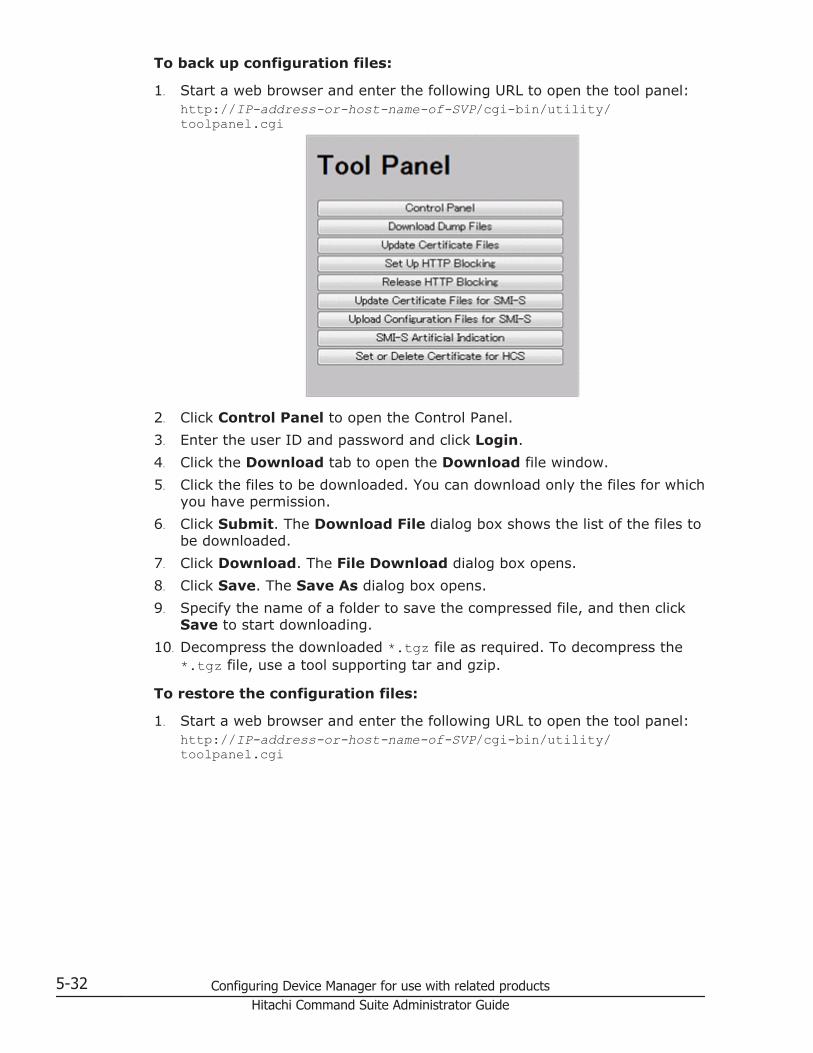
To back up configuration files:
1. Start a web browser and enter the following URL to open the tool panel:http://IP-address-or-host-name-of-SVP/cgi-bin/utility/toolpanel.cgi
2. Click Control Panel to open the Control Panel.3. Enter the user ID and password and click Login.4. Click the Download tab to open the Download file window.5. Click the files to be downloaded. You can download only the files for which
you have permission.6. Click Submit. The Download File dialog box shows the list of the files to
be downloaded.7. Click Download. The File Download dialog box opens.8. Click Save. The Save As dialog box opens.9. Specify the name of a folder to save the compressed file, and then click
Save to start downloading.10. Decompress the downloaded *.tgz file as required. To decompress the
*.tgz file, use a tool supporting tar and gzip.
To restore the configuration files:
1. Start a web browser and enter the following URL to open the tool panel:http://IP-address-or-host-name-of-SVP/cgi-bin/utility/toolpanel.cgi
5-32 Configuring Device Manager for use with related productsHitachi Command Suite Administrator Guide

2. Click Control Panel to open the Control Panel.3. Enter the user ID and password and click Login.4. Click the Restore tab to open the Restore file window.5. Click the files and click Browse to specify the directory of the file. You
can restore only the files for which you have permission.6. Click Next.7. Click the configuration files to restore.8. Click Submit.9. If the Password check dialog box opens, enter User ID, Password,
and Re-enter Password of the storage administrator on the backup userlist, and click Submit on the Password check dialog box.The Restore File dialog box opens.
10. Confirm the restoring process has been completed successfully.11. Click Close to close the dialog box.
Installing the report configuration toolComplete the following instructions to install the report configuration tool.
Prerequisites
You need the following items to install the report configuration tool:
• A Windows computer running Windows Server 2003, or WindowsServer 2008.You can use either an IPv4 address or an IPv6 address to connect the SVPto the windows computer. You can also connect the computer to the SVPover an IPv4 proxy server. When you use the proxy server, specify aname and a port number of the proxy server as the HTTP_PROXYenvironment variable on the Windows computer. For example:SET HTTP_PROXY=http://proxy.xx.co.jp:8080
Configuring Device Manager for use with related products 5-33Hitachi Command Suite Administrator Guide

• A user account for exclusive use of the report configuration tool.To use the report configuration tool, you must create a user account thatis used exclusively for the report configuration tool. Assign the storageadministrator role (initial configuration) to this user account.
• The report configuration tool installation softwareThe Report Configuration Tool is located on the CD-ROM Disc 2, which isnamed Host PP. The installation procedure is located in Installationprocedure on page 5-34.
Installation procedure
To install the report configuration tool:
1. Insert the Report Configuration Tool installation CD into the CD-ROMdrive.
2. On the CD, navigate to the /program/Config_Report_CLI/Win32folder and double-click setup.exe. Follow the instructions on the screen.
3. When prompted, enter the name of the directory in which to install thereport configuration tool. The installer continues until the tool is installed.
Note: The directory where the report configuration tool is installed is notspecified as an application path. When necessary, specify the directory as theapplication path.
Using the report configuration toolYou can use the report configuration tool to create up to 20 configurationreports and then view or download them.
Report Configuration Tool command reference (raidinf commands)This section describes the raidinf commands, symbols, and reports used inDevice Manager - Storage Navigator.
raidinf command list and command description
The following lists the raidinf commands and symbols.
Table 5-6 raidinf command list
Command Description
raidinf add report Creates a report.
raidinf delete report Deletes a report.
raidinf download report Downloads a report.
raidinf get reportinfo Displays a list of reports.
5-34 Configuring Device Manager for use with related productsHitachi Command Suite Administrator Guide

Table 5-7 Conventions of the command format
Symbol Description
< > The item enclosed in this symbol is variable.
|Vertical bar
Symbol is placed between multiple items to indicate "or".For example:-A | -BSpecifies -A or -B.
[ ]Square brackets
The enclosed item can be omitted. If some items aredelimited by the vertical bar, specify one or omit all items.For example:[ -A ]Specifies nothing or specifies -A.[ -a | -b ]Specifies nothing or specifies -a or -b.
{ }Curly brackets
The meaning differs depending on the enclosed item.• If items in curly brackets are delimited by vertical
bars, one of the items must be specified.For example:{-A | -B |-C }Specifies -A, -B, or -C.
• If curly brackets enclose items enclosed by squarebrackets, at least one of the items must be specified.For example:{[ -A ][ -B ][ -C ]}Specifies one or more items from -A, -B, or -C.
raidinf command syntax
The syntax of the raidinf commands and the basic format of the options andparameters are described next.
Syntaxraidinf [-h] <action> <object> –servername <hostname/ipaddress> [ {-report <report_name> | -report_id <report_id>}] [-targetfolder <folder>] [-fill]
raidinf [-h] –login <user_name> <password> –servername <hostname/ipaddress>
raidinf [-h] –logout –servername <hostname/ipaddress>
Configuring Device Manager for use with related products 5-35Hitachi Command Suite Administrator Guide

Options and parameters
Option Description
[-h] Displays help for raidinf.
<action> Specifies command operation. You can specify the followingcommands.• get: Displays a list of reports.
• add: Creates a report.
• delete: Deletes a report.
• download: Downloads a report.
<object> Specifies an operation target object. You can specify thefollowing objects.• reportinfo to display a list of reports.
• report to create, delete, or download a report.
-servername <hostname/ipaddress>
Specifies the host name or the IP address of the SVP.
[ {-report<report_name> | -report_id <report_id>}]
• -report specifies a report name within 32 characters.If you specify more than 32 characters, the 33rd andsubsequent characters are ignored.
• -report_id specifies a report ID displayed by thereport list. Because a report ID is a unique ID to eachof the reports, a specific report can be identified even ifreports of the same name exist.
[-targetfolder <folder>] Specifies a folder name to which a report is downloaded.The folder whose name you specify must already exist andyou must have permissions to the folder.
[-fill] Deletes a report only if the number of created reports is 20.
-login [<user_name><password>]
Executes a user authentication for Device Manager -Storage Navigator. Specifies a user name and a password.The user is logged out automatically three minutes (180seconds) after the last command is entered.
-logout Logs out of Device Manager - Storage Navigator.
Examples
This example authenticates user01 using the password xxxxxx.# raidinf -login user01 xxxxxx -servername svp.xxx.co.jpThis example executes a logout.# raidinf -logout -servername svp.xxx.co.jpDisplays help.# raidinf -hModel : RAIDINF/WindowsNTVerandRev: 01-00-03/00
Usage: raidinf [options] raidinf <action> <object> [parameters]
5-36 Configuring Device Manager for use with related productsHitachi Command Suite Administrator Guide

Options: -h Help/Usage -login <user_name> <password> Specify LOGIN explicitly -logout Specify LOGOUT
<User authentification> <option> <parameters> -login <user_name> <password> -servername <hostname/ipaddress> -logout -servername <hostname/ipaddress>
<Report management> <action> <object> <parameters> get reportinfo -servername <hostname/ipaddress> add report -servername <hostname/ipaddress> [-report <report_name>] download report -servername <hostname/ipaddress> {-report <report_name> | -report_id <report_id>} -targetfolder <folder> delete report -servername <hostname/ipaddress> {-report <report_name> | -report_id <report_id>} [-fill]
Parameters: -servername <hostname/ipaddress> Specify the SVP hostname or IP address. -report <report_name> Specify the Report Name. -report_id <report_id> Specify the ReportID. -targetfolder <folder> Specify the download folder. -fill Report is deleted only full of the server reports.
raidinf add report
The raidinf add report command creates a report.
If other users have created 20 reports, the logged in user cannot create areport and will receive an error.
Syntaxraidinf add report –servername <hostname/ipaddress> [-report <report_name>]
Options and parameters
Option Description
-servername <hostname/ipaddress>
Specifies the host name or the IP address of the SVP.
[-report <report_name>] Specifies a report name, up to 32 characters. If you specifymore than 32 characters, the 33rd and subsequentcharacters are ignored.If the report name is omitted, the default report nameYYMMDD-CreateConfigurationReport is specified.
The hyphen (-) cannot be specified at the beginning of thereport name.
Configuring Device Manager for use with related products 5-37Hitachi Command Suite Administrator Guide

Examples
This example creates a report with the default report name.# raidinf add report -servername 10.213.74.121ReportName UserName CreateTime101009-CreateConfigurationReport user01 2010/10/09-12:43:10This example specifies the report name 101009-CreateConfigurationReportand creates a report.# raidinf add report -servername 10.213.74.121 -report101009-CreateConfigurationReportReportName UserNameCreateTime101009-CreateConfigurationReport user01 2010/10/09-12:43:10The respective items of the output example are explained next.
• ReportNameThe report name is displayed (up to 32 characters).
• UserNameThe user name is displayed (up to 16 characters). If the user nameexceeds 16 characters, an ellipsis (...) is displayed.
• CreateTimeThe time of creating a report is displayed (up to 19 characters).
raidinf delete report
The raidinf delete report command deletes a report.
If multiple reports of the same name exist, the command deletes the oldestreport. If the specified report does not exist, the command does not doanything and is normally terminated.
Reports created using Device Manager - Storage Navigator can also bedeleted.
Syntaxraidinf delete report -servername <hostname/ipaddress>{-report<report_name> | -report_id <report_id>} [-fill]
Options and parameters
Option Description
-servername <hostname/ipaddress>
Specifies the host name or the IP address of the SVP.
{-report <report_name>| -report_id<report_id>}
Specifies either -report or -report_id.
• -report specifies a report name (up to 32 characters).If you specify more than 32 characters, the 33rd andsubsequent characters are ignored.
5-38 Configuring Device Manager for use with related productsHitachi Command Suite Administrator Guide

Option Description
• -report_id specifies a report ID displayed by thereport list. Because a report ID is a unique ID to eachof the reports, a specific report can be identified even ifreports of the same name exist.
[-fill] Deletes the report only if the total number of reports is 20.In there are less 20 reports, the specified report is notdeleted even if it exists.
Examples
This example specifies the report name 101009-CreateConfigurationReportand deletes the report.# raidinf delete report -servername 10.213.74.121 -report 101009-CreateConfigurationReport101009-CreateConfigurationReport is deleted in the SVP.
raidinf download report
The raidinf download report command downloads a report.
Reports created by Device Manager - Storage Navigator can also bedownloaded. The report in process of creation cannot be downloaded.
The name of the downloaded file is Report_report name.tgz. Note that thefiles are overwritten if reports of the same name has already existed.
Example: the name of the downloaded file when the report name is 110309-CreateConfigurationReportReport_110309-CreateConfigurationReport.tgz
Syntaxraidinf download report -servername <hostname/ipaddress> {-report <report_name> | -report_id <report_id>} -targetfolder <folder>
Options and parameters
Option Description
-servername <hostname/ipaddress>
Specifies the host name or the IP address of the Web server(SVP).
{-report <report_name>| -report_id<report_id>}
Specifies either -report or -report_id.
• -report: specifies a report name within 32 characters.If you specify more than 32 characters, the 33rd andsubsequent characters are ignored.If a special name LatestReport is specified as a reportname, the report created on the newest date isdownloaded.
Configuring Device Manager for use with related products 5-39Hitachi Command Suite Administrator Guide

Option Description
To download another report having the same name asthe special name "LatestReport", specify the relevantreport ID in -report_id. If multiple reports of the samename exist, the report of the newest date is the targetof download.
• -report_id: specifies a report ID displayed by thereport list. As a report ID is a unique ID to each of thereports, a specific report can be identified even ifreports of the same name exist.
-targetfolder <folder> Specifies a folder name to which a report is downloaded.The folder whose name you specify must already exist andyou have permissions to the folder.
Examples
Downloads the most recently created report.# raidinf download report -servername 10.213.74.121 -report LatestReport -targetfolder C:\tmpReport_101009-CreateConfigurationReport.tgz is downloaded to C:\tmp.
This example specifies the report name 101009-CreateConfigurationReportand downloads the report.# raidinf download report -servername 10.213.74.121 -report 101009-CreateConfigurationReport -targetfolder C:\tmpReport_101009-CreateConfigurationReport.tgz is downloaded to C:\tmp.
raidinf get reportinfo
The raidinf get reportinfo command displays a list of reports.
Reports created using Device Manager - Storage Navigator are also displayed.A report currently being created cannot be downloaded.
Syntaxraidinf get reportinfo –servername <hostname/ipaddress>
Options and parameters
Option Description
-servername <hostname/ipaddress>
Specifies the host name or the IP address of the Web server(SVP).
Examples
Displays a list of reports.# raidinf get reportinfo -servername 10.213.74.121ReportName UserName CreateTime ReportID
5-40 Configuring Device Manager for use with related productsHitachi Command Suite Administrator Guide

101009-CreateConfigurationReport user01 2010/10/09-12:43:10 33S3101008-CreateConfigurationReport user01 2010/10/08-11:22:31 33J3101007-CreateConfigurationReport user01 2010/10/07-11:17:20 2344101006-CreateConfigurationReport configuration... 2010/10/06-15:30:42 4n1jThe respective items of the output example are explained next.
• ReportNameThe report name is displayed (up to 32 characters).
• UserNameThe user name is displayed (up to 16 characters). If the user nameexceeds 16 characters, an ellipsis (...) is displayed.
• CreateTimeThe time of creating a report is displayed (up to 19 characters).
• ReportIDThe report ID is displayed.
Creating a configuration report using the Report Configuration ToolYou can create a configuration report by using a command prompt when youuse the Report Configuration Tool. By preparing a script file that contains aseries of commands and scheduling a task in Windows to execute the scriptat regular intervals, you can automate the creation and the deletion of theconfiguration report.
Preparing a script file
Before creating the configuration report, you will need to write a series ofcommands in a script file. When you run the Report Configuration Tool, thecommands in the script files execute sequentially and then create or delete aconfiguration report. See Report Configuration Tool command reference(raidinf commands) on page 5-34 for a list of commands.
Two examples of scripts are shown below. Refer to these examples as neededto create a script file that suits your needs.
• Example script for creating a configuration report on page 5-41• Example script for downloading a configuration report on page 5-43
Example script for creating a configuration report
This script logs the user in, deletes a configuration report, creates aconfiguration report, and logs the user out, using the Report ConfigurationTool.
For each command except the logout command, this example performs threeretries at intervals of 2 minutes, assuming that communication errors andother errors can occur. In addition, the delete report command is executedwith the -fill option before the add report command, so that the scriptdoes not terminate when 20 configuration reports accumulate in the SVP.
Configuring Device Manager for use with related products 5-41Hitachi Command Suite Administrator Guide

REMREM Create Report Script(CreateReport.bat) REMSET USER=<Username for Device Manager - Storage Navigator>SET PASS=<Password for Device Manager - Storage Navigator>SET SERVER=<Hostname or IP address of SVP>SET REPORT_NAME=DailyConfigurationReportSET LOOP=2REM LOOP:0-2 3TimesSET TIMEOUT=121REM TIMEOUT 2[minutes]=120[s]SET RAIDINF_PATH="C:\Program Files\raidinf"SET /a CNT_LOGIN=0
:LOGIN_RETRYREM ############################# LOGIN %CNT_LOGIN%SET /a CNT_LOGIN=%CNT_LOGIN% + 1%RAIDINF_PATH%\raidinf -login %USER% %PASS% -servername %SERVER%if ERRORLEVEL 1 ( if %CNT_LOGIN% GTR %LOOP% GOTO :ABEND CALL :SLEEP GOTO LOGIN_RETRY)
SET /a CNT_DEL=0:DEL_RETRYREM ############################# DELETE %CNT_DEL%SET /a CNT_DEL=%CNT_DEL% + 1%RAIDINF_PATH%\raidinf delete report -servername %SERVER% ^-report %REPORT_NAME% -fillif ERRORLEVEL 1 ( IF %CNT_DEL% GTR %LOOP% GOTO :ABEND CALL :SLEEP GOTO :DEL_RETRY)
SET /a CNT_ADD=0:ADD_RETRYREM ############################# ADD %CNT_ADD%SET /a CNT_ADD=%CNT_ADD% + 1%RAIDINF_PATH%\raidinf add report -servername %SERVER% -report ^%REPORT_NAME%if ERRORLEVEL 1 ( IF %CNT_ADD% GTR %LOOP% GOTO :ABEND CALL :SLEEP GOTO ADD_RETRY) GOTO :ENDEXIT /B
:SLEEPREMREM ############################# SLEEP with %TIMEOUT% secREMping 127.0.0.1 -n %TIMEOUT% > NULEXIT /B
:ABENDREM ############################# ABENDECHO "Create Report Script was ABEND"
5-42 Configuring Device Manager for use with related productsHitachi Command Suite Administrator Guide

:ENDREM ############################# Logout%RAIDINF_PATH%\raidinf -logout -servername %SERVER%
Example script for downloading a configuration report
This script logs the user in, downloads a configuration report, and logs theuser out, using the Report Configuration Tool.
For each command except the logout command, this example performs 3retries at intervals of 2 minutes, assuming that communication errors andother errors can occur. The downloaded configuration report is accumulatedfor 3 generations in the C:\Reports folder by names fromReport_DailyConfigurationReport_1.tgz toReport_DailyConfigurationReport_3.tgz. In addition, if the script forcreating a configuration report fails, generation copy is terminated so that thepast configuration reports may not be overwritten.REMREM Download Report Script(DownloadReport.bat) REMSET USER=<Username for Device Manager - Storage Navigator>SET PASS=<Password for Device Manager - Storage Navigator>SET SERVER=<Hostname or IP Address of SVP>SET REPORT_NAME=DailyConfigurationReportSET LOOP=2REM LOOP:0-2 3TimesSET TIMEOUT=121REM TIMEOUT 2[minutes]=120[s]SET TARGETFOLDER=C:\Reports\tmpSET REPORTFOLDER=C:\ReportsSET RAIDINF_PATH="C:\Program Files\raidinf"REMREM Create Report FolderREMIF NOT EXIST %REPORTFOLDER% ( MKDIR %REPORTFOLDER% IF NOT EXIST %TARGETFOLDER% ( MKDIR %TARGETFOLDER% ) )
SET /a CNT_LOGIN=0:LOGIN_RETRYREM ####################################### Login %CNT_LOGIN%SET /a CNT_LOGIN=%CNT_LOGIN% + 1%RAIDINF_PATH%\raidinf -login %USER% %PASS% -servername %SERVER%if ERRORLEVEL 1 ( IF %CNT_LOGIN% GTR %LOOP% GOTO :ABEND CALL :SLEEP GOTO LOGIN_RETRY)
SET /a CNT_DL=0:DL_RETRYREM ####################################### Download %CNT_DL%SET /a CNT_DL=%CNT_DL% + 1%RAIDINF_PATH%\raidinf download report -servername %SERVER% ^
Configuring Device Manager for use with related products 5-43Hitachi Command Suite Administrator Guide

-report %REPORT_NAME% -targetfolder %TARGETFOLDER%if ERRORLEVEL 1 ( IF %CNT_DL% GTR %LOOP% GOTO :ABEND CALL :SLEEP GOTO :DL_RETRY)
REM ####################################### Create Error CheckIF EXIST %REPORTFOLDER%\Report_%REPORT_NAME%_1.tgz ( IF EXIST %TARGETFOLDER%\Report_%REPORT_NAME%.tgz ( GOTO :FC_CHECK ) else ( GOTO :CHECK_END ) ) else ( GOTO :CHECK_END)
:FC_CHECKFC /B %REPORTFOLDER%\Report_%REPORT_NAME%_1.tgz ^%TARGETFOLDER%\Report_%REPORT_NAME%.tgz > NULif ERRORLEVEL 1 ( REM) else ( DEL %TARGETFOLDER%\Report_%REPORT_NAME%.tgz GOTO :END)
:CHECK_ENDREM ####################################### Migrate ReportsIF EXIST %TARGETFOLDER%\Report_%REPORT_NAME%.tgz ( IF EXIST %REPORTFOLDER%\Report_%REPORT_NAME%_2.tgz ( COPY %REPORTFOLDER%\Report_%REPORT_NAME%_2.tgz ^%REPORTFOLDER%\Report_%REPORT_NAME%_3.tgz ) IF EXIST %REPORTFOLDER%\Report_%REPORT_NAME%_1.tgz ( COPY %REPORTFOLDER%\Report_%REPORT_NAME%_1.tgz ^%REPORTFOLDER%\Report_%REPORT_NAME%_2.tgz) IF EXIST %TARGETFOLDER%\Report_%REPORT_NAME%.tgz ( COPY %TARGETFOLDER%\Report_%REPORT_NAME%.tgz ^%REPORTFOLDER%\Report_%REPORT_NAME%_1.tgz DEL %TARGETFOLDER%\Report_%REPORT_NAME%.tgz ) ) GOTO :ENDEXIT /B
:SLEEPREM ####################################### SLEEP with %TIMEOUT%ping 127.0.0.1 -n %TIMEOUT% > NULEXIT /B
:ABENDREM ####################################### ABENDECHO "Download Report Script was ABEND"
:ENDREM ####################################### Logout%RAIDINF_PATH%\raidinf -logout -servername %SERVER%
5-44 Configuring Device Manager for use with related productsHitachi Command Suite Administrator Guide

Example execution and explanation of script files
• The first time you execute the script files to create a configuration reportand download a configuration file, theReport_DailyConfigurationReport_1.tgz file is created in the C:\Reports folder.
• On the second day:Report_DailyConfigurationReport_1.tgz is renamedReport_DailyConfigurationReport_2.tgz, andReport_DailyConfigurationReport_1.tgz is newly created.
• From the third day on:Report_DailyConfigurationReport_1.tgz andReport_DailyConfigurationReport_2.tgz are renamedReport_DailyConfigurationReport_2.tgz andReport_DailyConfigurationReport_3.tgz, andReport_DailyConfigurationReport_1.tgz are newly created. BecauseReport_DailyConfigurationReport_3.tgz is overwritten, the reports forthree days are always accumulated in the C:\Reports folder.
C:\Reports CreateReport.bat DownloadReport.bat Report_DailyConfigurationReport_1.tgz <-Generated today Report_DailyConfigurationReport_2.tgz <-Generated yesterday Report_DailyConfigurationReport_3.tgz <-Generated two days ago
Error in executing Report Configuration Tool
When using the Report Configuration Tool, you may see Device Manager -Storage Navigator error codes and other error codes that are unique to theReport Configuration Tool. For Device Manager - Storage Navigator errorcodes, see Hitachi Command Suite Messages. The error codes unique to theReport Configuration Tool and the corresponding actions are as follows.
Error code Error message Cause of error and action Returnvalue
EW_COMERR A certificate does notbecome effective.Please login again.
A certain period of time elapsedafter a login. Log in again.
131
EW_COMERR Login is necessary.Please login again.
A command was entered beforelogging in. Log in and then enterthe command.
131
EW_ENFILE No such folder.Please refer to the help.
The specified folder to downloadto is not found. See ReportConfiguration Tool commandreference (raidinf commands) onpage 5-34 and specify theparameter again.
131
EW_ENOMEM Memory allocate error.Please other programterminate.
Allocation of internal memoryfails. Close unnecessaryprograms or reboot the server.
245
Configuring Device Manager for use with related products 5-45Hitachi Command Suite Administrator Guide

Error code Error message Cause of error and action Returnvalue
EW_INVOPA Report name reserved.Please check input '-report' parameter.
You cannot use the report namespecified by the -report option.Check the report name andspecify a new one.
131
EW_INVOPT Invalid option.Please refer to the help.
The hyphen (-) is not added tothe option parameter. SeeReport Configuration Toolcommand reference (raidinfcommands) on page 5-34 andrevise the parameters.
131
EW_LNGARG Argument too long.Please refer to the help.
Either of the following causes ispossible.• The length of a parameter of
the command exceeds 256bytes.
• The length of all theparameters of the commandexceeds 1,021 bytes.
See Report Configuration Toolcommand reference (raidinfcommands) on page 5-34 andspecify a new parameter.
131
EW_MAXAPP Maximum applicationstart.Please check startingapplication.
The maximum number of SVPsthat you can connectsimultaneously is exceeded. Logout of unnecessary SVPs andreconnect.
131
EW_MAXARG Maximum argument.Please refer to the help.
The number of parameters ofthe command exceeds 10. SeeReport Configuration Toolcommand reference (raidinfcommands) on page 5-34 andrevise the parameters.
131
EW_REQOPT Required option list.Please refer to the help.
The required option andparameters were not entered.See Report Configuration Toolcommand reference (raidinfcommands) on page 5-34 andspecify a valid option andparameters.
131
EW_SYSERR System error.Please call to servicecenter.
An internal error occurred.Contact Hitachi Data SystemsSupport Center.
131
EW_SYSERR Install path is too long.Specify the install pathwith up to 240 bytes.
The installation path exceeds240 bytes. Specify no more than240 bytes.
131
EW_SYSERR Certificate file invalid. Updating certificate file fails.Contact Hitachi Data SystemsSupport Center.
131
5-46 Configuring Device Manager for use with related productsHitachi Command Suite Administrator Guide
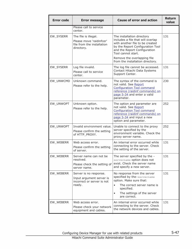
Error code Error message Cause of error and action Returnvalue
Please call to servicecenter.
EW_SYSERR The file is illegal.Please move 'raidinfcer'file from the installationdirectory.
The installation directoryincludes a file that will overlapwith another file to be createdby the Report Configuration Tooland the Report ConfigurationTool cannot start.Remove the overlapping filefrom the installation directory.
131
EW_SYSERR Log file invalid.Please call to servicecenter.
The log file cannot be accessed.Contact Hitachi Data SystemsSupport Center.
131
EW_UNWCMD Unknown command.Please refer to the help.
The syntax of the command isnot valid. See ReportConfiguration Tool commandreference (raidinf commands) onpage 5-34 and enter a validparameter.
230
EW_UNWOPT Unknown option.Please refer to the help.
The option and parameter arenot valid. See ReportConfiguration Tool commandreference (raidinf commands) onpage 5-34 and input a newoption and parameter.
252
EW_UNWOPT Invalid environment value.Please confirm the settingof HTTP_PROXY.
Unable to connect to the proxyserver specified by theenvironment variable. Check theproxy server name.
252
EW_WEBERR Web access error.Please confirm the settingof server.
An internal error occurred whileconnecting to the server. Checkthe setting of the server.
131
EW_WEBERR Server name can not beresolved.Please check the setting ofserver name.
The server specified by the -servername option does notexist. Check the server nameand specify a new server.
131
EW_WEBERR Server is no response.Input argument server isincorrect or server is notready.
No response from the serverspecified by the-servernameoption. Make sure that:• The correct server name is
specified.• The settings of the server
are correct.
131
EW_WEBERR Web access error.Please check your networkequipment and cables.
An internal error occurred whileconnecting to the server. Checkthe network devices and cables.
131
Configuring Device Manager for use with related products 5-47Hitachi Command Suite Administrator Guide

Error code Error message Cause of error and action Returnvalue
EW_WEBERR Web access error.Please confirm the settingof proxy server.
An internal error occurred whileconnecting to the proxy server.Check the settings of the proxyserver.
131
EW_WEBERR Proxy server name cannot be resolved.Please check the setting ofproxy server name.
Unable to connect to the proxyserver specified by theenvironment variable. Check theproxy server name.
131
EX_CMDRJE The control commandrejected.
The execution of the enteredcommand was rejected by theserver.Check the error messages ofDevice Manager - StorageNavigator.
221
Executing a regularly scheduled script file
To execute the created script file on a regular basis, register it as a scheduledtask in Windows.
The following procedure uses the Windows schtasks command to register thescript files created in the example shown in Preparing a script file on page5-41 as tasks of Windows.
Registration example
• Create a configuration report at 21:00 every day (CreateReport.bat).• Download a configuration report at 22:00 every day
(DownloadReport.bat).
Procedure
1. Store the two script files in the C:\Reports folder.C:\Reports CreateReport.bat DownloadReport.bat
2. Run the Windows schtasks command to register the two script files as atask of Windows.Make sure that the <Username for Windows> parameter of this commandis a user who has write permissions to the following two folders.
¢ C:\Reports folder¢ The log folder in the installation folder of the Report Configuration
Tool.schtasks /create /tn CreateReport /tr "C:\Reports\CreateReport.bat" /sc DAILY /st. 21:00:00 /ru <Usernamefor Windows> /rp <Password for Windows> schtasks /
5-48 Configuring Device Manager for use with related productsHitachi Command Suite Administrator Guide

create /tn DownloadReport /tr "C:\Reports\DownloadReport.bat" /sc DAILY /st 22:00:00 /ru <Usernamefor Windows> /rp <Password for Windows>
3. Run the schtasks /Query command to confirm that the Windows task isregistered.C:\>schtasks /QueryTask name Time of next execution Status============= ====================== ===============CreateReport 21:00:00, 2011/05/17DownloadReport 22:00:00, 2011/05/17
Downloading dump files using the Dump toolUse the Dump tool to download dump files onto a web client. The downloadeddump files can be used to:
• troubleshoot the system. Use the Dump tool to download dump files fromthe SVP and give it to the HDS support personnel.
• check system configuration. First click File > Refresh All to refresh theconfiguration information, and then use the Dump tool to download dumpfiles.
Prerequisites
• All other users (including the SVP user) must stop using the Dump tool.• Stop all maintenance operations.• You must have Support Personnel role to log in.
To download dump files from the SVP:
1. Start a web browser and specify the following URL to open the Tool Panel:https://IP-address-or-host-name-of-SVP/cgi-bin/utility/toolpanel.cgi
2. Click Download Dump Files. The Login dialog box opens.
Configuring Device Manager for use with related products 5-49Hitachi Command Suite Administrator Guide

3. Enter the user ID and password and click Login. The Download DumpFiles dialog box opens.
4. Select a file that you want to download.
¢ Existing Dump Files indicates the last dump file that youdownloaded. Select this when you want to re-download a previouslydownloaded dump file. If you have not downloaded any dump filesfrom the Tool Panel, this item does not display even if you haveacquired a dump file via SVP.
¢ Normal Dump includes all information about the SVP and theminimum information about the storage system. Select this when youhave a less serious problem such as incorrect display.
¢ Detail Dump includes all information about the SVP and the storagesystem. Select this when Device Manager - Storage Navigator has aserious problem (for example, Device Manager - Storage Navigatordoes not start) or when you need to determine if the storage systemhas a problem.
¢ Detail Dump (for DKC Performance) contains the I/O-performance-related information. This includes performance monitorcollection information, in addition to information applicable to DetailDump. Choose Detail Dump (for DKC Performance) to check forI/O performance problems.Note that while processing takes place, DKC I/O performance may beaffected. During processing, you cannot use Device Manager - StorageNavigator to change the system configuration or perform SVPmaintenance operations.
5. Click Next. A message appears confirming the execution of compressionof the dump files.
6. Click OK. File compression processing starts. When the file iscompressed, the Download Dump Files dialog box opens for thedownload.
7. Click Download. The File Download dialog box opens.8. On the File Download dialog box, click Save this file to disk, and then
click OK. The Save As dialog box opens.9. Specify the download destination, and then click Save. When the file is
downloaded successfully, the Download complete dialog box opens.
5-50 Configuring Device Manager for use with related productsHitachi Command Suite Administrator Guide

6Setting up logs and alerts
This chapter describes the settings required to use the Hitachi CommandSuite products to monitor the status of the system and errors.
□ Setting up Hitachi Command Suite common trace log files
□ Setting up alerts
□ Sending SNMP traps to log files
□ Using event notification
□ Reporting failure information about storage systems (for VSP G1000 only)
Setting up logs and alerts 6-1Hitachi Command Suite Administrator Guide

Setting up Hitachi Command Suite common trace log filesCommon Component provides a common library used for logging. HitachiCommand Suite products use this library to output trace log information tolog files.
Setting up Hitachi Command Suite common trace log files (Windows)To change the number or size of Hitachi Command Suite common trace logfiles, use the Windows HNTRLib2 utility.
WARNING: Changing settings affects other program products that useHitachi Command Suite common trace logs.
Operations to complete in advance
Log in to the system as a member of the Administrators group.
To set up trace log files:
1. Execute the Windows HNTRLib2 utility stored in the following location:program-files-folder\Hitachi\HNTRLib2\bin\hntr2util.exe
2. In the Hitachi Network Objectplaza Trace Utility 2 dialog box, for Numberof Files, specify the number of trace log files.You can set a maximum of 16 trace log files. The default is 4.
3. In the Hitachi Network Objectplaza Trace Utility 2 dialog box, for FileSize, specify the size of the trace log files.When the size of a trace log file has reached the specified value, the nexttrace log file is used.You can specify the trace log file size in the range from 8 KB to 4096 KB.The default is 256 KB. Specify a value greater than the value specified forBuffer.
4. Click OK.5. Restart the OS to apply the changes.
Setting up Hitachi Command Suite common trace log files (Linux)To change the number or size of Hitachi Command Suite common trace logfiles, use the utility program (hntr2util).
WARNING: Changing settings affects other program products that useHitachi Command Suite common trace logs.
Operations to complete in advance
Log in to the system as a root user.
To set up trace log files:
1. Execute the utility program stored in the following location:
6-2 Setting up logs and alertsHitachi Command Suite Administrator Guide

/opt/hitachi/HNTRLib2/bin/hntr2util2. In the menu, select 2 (Number of log files).3. In the submenu, enter the desired number for trace log files, and then
press Enter.You can set a maximum of 16 trace log files. The default is 4.
4. In the menu, select 1 (Size of a log file).5. In the submenu, enter the desired number for trace log files, and then
press Enter.When the size of a trace log file has reached the specified value, the nexttrace log file is used.You can specify the trace log file size in the range from 8 KB to 4096 KB.The default is 256 KB. Specify a value greater than the value specified forSize of buffer.
6. Check the contents you specified, enter e, and then press Enter.7. Enter y to save the changes.8. Execute the following command to delete the memory mapped file:
# rm /opt/hitachi/HNTRLib/mmap/hntrmmap.mm9. Restart the OS to apply the changes.
Setting up alertsIn Device Manager, information about errors that occurred in management-target storage systems or file servers is displayed in the Device ManagerGUI/CLI as alerts. Alerts can also be sent by email.
Error detection by Device ManagerDevice Manager detects errors in management-target storage systems or fileservers as follows:
• Polling (default)Device Manager regularly monitors the operating status of the storagesystems and file servers, and displays an alert when an error is detected.An alert includes the location where an error occurred and overview of theerror.The polling interval can be set by using theserver.dispatcher.daemon.pollingPeriod property of the DeviceManager server.
• SNMP traps (optional)When SNMP traps are received from storage systems or file servers, theyare displayed as alerts. SNMP traps are useful for determining the causeof an error, because they include information about the location of theerror in addition to the site of the error.To receive SNMP traps in Device Manager, you must specify environmentsettings.
Setting up logs and alerts 6-3Hitachi Command Suite Administrator Guide

The alerts that Device Manager can display differ depending on the storagesystems and file servers. The table below lists the alerts that are supportedby each storage system or file server.
Table 6-1 Alerts that can be displayed by Device Manager
Management target Polling SNMP trapsEmail
notificationof alerts
Storagesystem
VSP G1000 Y Y Y
Virtual StoragePlatform
Y Y Y
Universal StoragePlatform V/VM
Y Y Y
Hitachi USP Y Y Y
HUS VM Y Y Y
HUS100 Y -- Y
Hitachi AMS2000 Y -- Y
Hitachi SMS Y -- Y
Hitachi AMS/WMS Y -- Y
SMI-S enabled storagesystems
-- -- --
File server Hitachi Data Ingestor -- Y --
Hitachi NAS Platform Y# Y# Y#
Hitachi NAS Platform F -- Y --
LegendY: Supported--: Not supported
#: For Hitachi NAS Platform, both of the following conditions must besatisfied to detect error information:
• The version of Hitachi NAS Platform is 12.0 or later.• Admin services EVS is set.
Note: For Hitachi NAS Platform, the timing of when polls and SNMP trapsdetect errors is different, but the same information is displayed in their alerts.Set SNMP traps only when you want to receive alerts in intervals less than 5minutes. The default obtains alerts by polling in 5-minute intervals.
Related topics
• Settings for displaying SNMP traps as alerts on page 6-5• Changing Device Manager server properties on page A-4• server.dispatcher.daemon.pollingPeriod on page A-21
6-4 Setting up logs and alertsHitachi Command Suite Administrator Guide

Settings for displaying SNMP traps as alertsTo display SNMP traps as alerts, the following settings are required:
• Settings for Device Manager to receive SNMP traps
¢ Device Manager must be able to use port 162/udp of the managementserver.
¢ Specify true for the server.dispatcher.daemon.receiveTrapproperty.
• Settings for reporting SNMP traps to Device Manager
¢ For storage systems, the IP address of the management server mustbe registered in the SNMP Agent settings.
¢ For Hitachi NAS Platform, the host name or IP address of themanagement server and a port number (162/udp) must be set fromSMU or the Hitachi NAS Platform CLI as a target for trap notifications.Make the format of the IP address (IPv6 or IPv4) to be set match thefollowing:
Table 6-2 IP address format for the management server to be set(setting SNMP traps for Hitachi NAS Platform)
Conditions IP address format(IPv6 or IPv4)
The setting for SNMP traps to be sent from Adminservices EVS is set in the Hitachi NAS Platform CLI.
Match the format with theIP address format forAdmin services EVS
The setting for SNMPtraps to be sent fromAdmin services EVS is notset in the Hitachi NASPlatform CLI.
An EVS for mounting thefile system exists.
Match the format with theIP address format for EVSwhere the file system is tobe mounted.
An EVS for mounting thefile system does notexist.
Match the format with theIP address format for thefile server (node).
¢ For Hitachi Data Ingestor, the host name or IP address of the DeviceManager management server and a port number (162/udp) must beset in Hitachi File Services Manager.
After the above settings finish, the Device Manager server receives SNMPtraps from all communities and displays them as alerts.
Related topics
• Changing Device Manager server properties on page A-4• server.dispatcher.daemon.receiveTrap on page A-21
Setting up logs and alerts 6-5Hitachi Command Suite Administrator Guide

Operation flow for reporting alerts by emailWhen an alert is issued, the alert can be automatically reported to users byemail. This enables users to be aware of failures that have occurred instorage systems or file servers without logging in to the management client.
The settings required for sending alerts to users by email are describedbelow.
1. Setting up the SMTP serverSet the SMTP server so that the Device Manager server can connect tothe SMTP server. Follow the procedure for setting the SMTP server to beused.
2. Registering recipients of email alertsIn the Device Manager GUI, register the users who will receive emails.
3. Setting properties for reporting alertsSet the SMTP server information and the email address from which alertsare reported as properties of the Device Manager server.
4. Registering an SMTP authentication user account (when SMTPauthentication is used)Register an SMTP authentication user account in the Device Managerserver. If an SMTP authentication user account has already beenregistered due to event notification or notification of the health checkresults, you do not have to register it again.
5. Customizing email alert template (optional)Edit the template file as necessary, and set the email output contents.
Note:
• Device Manager sends email only once when an alert is issued. If theDevice Manager server fails to send an email, the same email will not besent again. Information on an alert and email address of the intendeddestination of this email, are output to the Device Manager trace log file.
• If the Device Manager server service stops before the Device Managerserver sends an email about an alert, the email will not be sent. In thiscase, even if the Device Manager server service is started again, theDevice Manager server will not send the email that has not been sent.After the Device Manager server service is started again, execute theGetAlerts command from the CLI or use the alert management functionfrom the GUI, to make sure that actions have been taken for every alert.
• When you create environments or perform maintenance on storagesystems or file servers that have already been registered in the DeviceManager server, the storage systems or file servers might generate a lotof alerts. We recommend that you disable the email notification functionbeforehand by specifying false for theserver.mail.enabled.storagesystem property orserver.mail.enabled.fileserver property of the Device Managerserver.
6-6 Setting up logs and alertsHitachi Command Suite Administrator Guide

Related topics
• Changing Device Manager server properties on page A-4• server.mail.enabled.storagesystem on page A-12• server.mail.enabled.storagesystem on page A-12
Setting up the SMTP server
Set up your SMTP server so that the Device Manager can connect to it.
Make sure that you specify the authentication methods in the SMTP serverthat you use. The Device Manager server supports the following SMTPauthentication methods: LOGIN or PLAIN.
Note:
• When there are multiple SMTP authentication methods that the SMTPserver specifies, the Device Manager server selects an authenticationmethod (LOGIN or PLAIN in that priority order), and then sends an email.If LOGIN or PLAIN is not specified, the Device Manager server will send anemail without using the SMTP authentication.
• If SMTP authentication is disabled on the SMTP server, even if the settingis enabled on the Device Manager server, the Device Manager server willsend an email without using SMTP authentication.
Registering recipients of email alerts
Use the Device Manager GUI to set an email destination user.
The conditions required for email destination users are shown below. Emailswith the same contents are sent to the users who meet these conditions.
• The resource groups that correspond to the resources to be managed areassigned.
• Modify is set as the role in Device Manager for the assigned resourcegroup.
• An email address is registered in the profile for the user.This setting is necessary if user accounts have been registered in HitachiCommand Suite products. If user accounts are managed by an externalauthorization server, register, on the external authorization server, theuser email addresses to be notified.
Tip: The users who receive emails need to use email software that supportsUnicode (UTF-8) encoding because, when sending an email, the DeviceManager server sets the character encoding of the email to Unicode (UTF-8).
Related topics
• How to register users in the Device Manager GUI : Hitachi CommandSuite User Guide
Setting up logs and alerts 6-7Hitachi Command Suite Administrator Guide

Property settings for reporting alerts
To report alerts by email, the SMTP server information and the email addressfrom which alerts are reported must be set for the properties in theserver.properties file of the Device Manager server.
The following properties must be set:
• server.mail.enabled.storagesystem• server.mail.enabled.fileserver• server.mail.from• server.mail.smtp.host• server.mail.smtp.port• server.mail.smtp.auth• server.mail.errorsTo• server.eventNotification.mail.to• server.mail.alert.type.storagesystem• server.mail.alert.status
Related topics
• Changing Device Manager server properties on page A-4• server.mail.enabled.storagesystem on page A-12• server.mail.enabled.fileserver on page A-12• server.mail.from on page A-13• server.mail.smtp.host on page A-13• server.mail.smtp.port on page A-13• server.mail.smtp.auth on page A-13• server.mail.errorsTo on page A-14• server.eventNotification.mail.to on page A-14• server.mail.alert.type.storagesystem on page A-14• server.mail.alert.status on page A-14
Registering an SMTP authentication user account in Device Manager
If SMTP authentication is enabled, use the hdvmmodmailuser command toregister an SMTP authentication user account in Device Manager. If an SMTPauthentication user has already been set for event notification or health checkresults email notification, then these settings are not required here.
Operations to complete in advance
• Log in as a user with Administrator permissions (for Windows) or as aroot user (for Linux).
• Set the server.mail.smtp.auth property of the Device Manager serverSpecify true.
6-8 Setting up logs and alertsHitachi Command Suite Administrator Guide

Information to collect in advance
• User ID and password for which All Resources has been assigned as aresource group and Admin has been set as the role in Device Manager.
• User ID and password used for SMTP authentication.
To register an SMTP authentication user account in Device Manager:
1. Execute the following command.
In Windows:installation-folder-for-Hitachi-Command-Suite\DeviceManager\HiCommandServer\tools\hdvmmodmailuser.bat -u Device-Manager-user-ID -p Device-Manager-password SMTP-authentication-user-ID [SMTP-authentication-password]
In Linux:installation-directory-for-Hitachi-Command-Suite/HiCommandServer/tools/hdvmmodmailuser.sh -u Device-Manager-user-ID -p Device-Manager-password SMTP-authentication-user-ID [SMTP-authentication-password]
2. Restart the Hitachi Command Suite product services.
Caution:
• If SMTP authentication is enabled on the Device Manager server, but anSMTP authentication user is not registered, email will be sent withoutusing SMTP authentication.
• Only one SMTP authentication user can be set on the Device Managerserver. The set SMTP authentication user information will be updatedeach time you execute the command.
• You cannot delete the SMTP authentication user information that you seton the Device Manager server.
Related topics
• Starting the Hitachi Command Suite services on page 8-4• Stopping the Hitachi Command Suite services on page 8-5• Changing Device Manager server properties on page A-4• server.mail.smtp.auth on page A-13
Customizing email alert template
Email contents can be changed in the template file (mail-alert-detection.txt). After changing the template file, restart the HitachiCommand Suite product services.
Operations to complete in advance
Log in as a user with Administrator permissions (for Windows) or as a rootuser (for Linux).
Setting up logs and alerts 6-9Hitachi Command Suite Administrator Guide

Use a text editor to edit the template file ( mail-alert-detection.txt )stored in the following location:.
In Windows:installation-folder-for-Hitachi-Command-Suite\DeviceManager\HiCommandServer\config
In Linux:installation-directory-for-Hitachi-Command-Suite/HiCommandServer/config
The following shows the settings of the default mail-alert-detection.txtfile:
Specify the mail-alert-detection.txt file so that all of the conditionsbelow are satisfied. If at least one condition is not satisfied, the DeviceManager server will create an email by using the default settings.
• Do not change the file name and location.• Specify a header in the first line, nothing in the second line, and the email
body and parameters in the third and following lines.• Specify a header in the format Subject: email-title.• Specify parameters in the format ${parameter-name}.
The parameter name is case sensitive.• Use UTF-8 encoding to code.• The file size must not exceed 64 KB.• The length of each line must not exceed 1024 bytes, excluding linefeed
characters.
The following table shows the specifiable parameters:
Table 6-3 Parameters you can set in the mail-alert-detection.txt file
Parameter name Description
messageID Alert ID
alertType Alert type
source Alert source
6-10 Setting up logs and alertsHitachi Command Suite Administrator Guide

Parameter name Description
For storage systems, the storage system nameFor Hitachi NAS Platform, the cluster name or node name
status Alert severity
component Component on which the problem occurredFor storage systems, the storage system componentwhere the alert occurredFor Hitachi NAS Platform, File Controller
description Alert description
recommendedAction Action to be taken for the alert
additionalInfo Supplementary information
occurrenceTime For storage systems, the time at which the DeviceManager server acquired alert informationFor Hitachi NAS Platform, the time at which an erroroccurred in Hitachi NAS PlatformDisplay format: yyyy/mm/dd hh:mm:sshh is displayed by using 24-hour display.
Related topics
• Starting the Hitachi Command Suite services on page 8-4• Stopping the Hitachi Command Suite services on page 8-5
Sending SNMP traps to log filesDevice Manager receives SNMP traps issued by devices on the network andoutputs them to log files. SNMP traps (SNMP version1 only) issued by devicesthat are not management targets can also be output to log files, as well asSNMP traps issued by the management-target storage systems.
Received SNMP traps are output to the following files:
• Event log or syslog• Hitachi Command Suite common trace log files (hntr2n.log)• Device Manager trace log files (HDvMtracen.log)• Trace log files (trace.log)• Error log files (error.log)#
#:Output only if the severity level is Error, Critical, or Alert. Theseverity levels for SNMP traps are specified for thecustomizedsnmptrap.customizelist property in thecustomizedsnmptrap.properties file.
The following SNMP trap information is output:
Setting up logs and alerts 6-11Hitachi Command Suite Administrator Guide

• Message ID indicating that a trap was received (prefix: KAID)• Sender (agent)• Enterprise ID (enterprise)• Generic trap number (generic)• Specific trap number (specific)
If integrated management software is linked with, you can centrally monitorthe operational status of all network resources, including the storageresources managed by Device Manager.
Related topics
• Setting up Device Manager to output SNMP traps on page 6-12• Changing Device Manager server properties on page A-4• customizedsnmptrap.customizelist on page A-34
Setting up Device Manager to output SNMP trapsTo set up Device Manager to receive SNMP traps and output them to log files,the following settings must be specified:
• Settings required for Device Manager to receive SNMP traps#
¢ Device Manager must be able to use port 162/udp of the managementserver.
¢ Specify true for the server.dispatcher.daemon.receiveTrapproperty.
• Settings required to report SNMP traps to Device Manager#
¢ The management server information must be registered in SNMPrelated software as the target for trap notification.For example, to receive storage system SNMP traps, SNMP Agentsettings must be specified.
• Settings required to output received SNMP traps to log files
¢ Specify true for thecustomizedsnmptrap.customizedSNMPTrapEnable property.
¢ The output contents must be set in thecustomizedsnmptrap.customizelist property.
#: These settings are the same as the settings required to display SNMPtraps in Device Manager GUI/CLI as alerts.
After the above settings finish, the Device Manager server receives SNMPtraps from all communities and outputs them to log files.
Related topics
• Changing Device Manager server properties on page A-4
6-12 Setting up logs and alertsHitachi Command Suite Administrator Guide

• server.dispatcher.daemon.receiveTrap on page A-21• customizedsnmptrap.customizedSNMPTrapEnable on page A-33• customizedsnmptrap.customizelist on page A-34
Using event notificationTiered Storage Manager uses email to report to users the results of eventsthat are not directly the result of user actions, such as the end of migrationand shredding tasks. The following events can be reported by email:
Table 6-4 Tiered Storage Manager events that can be reported via email
Event Description
Migration task ended This event occurs when a migration task endssuccessfully, ends due to a failure, or is canceled.
Shredding task ended This event occurs when a shredding task createdvia the Tiered Storage Manager CLI endssuccessfully, ends due to a failure, or is canceled.
Locking task ended This event occurs when a locking task created viathe Tiered Storage Manager CLI ends successfully,ends due to a failure, or is canceled.
Unlocking task ended This event occurs when an unlocking task createdvia the Tiered Storage Manager CLI endssuccessfully, ends due to a failure, or is canceled.
Volume lock period expired This event occurs when the volume lock periodhas expired for a volume in a migration groupcreated via the Tiered Storage Manager CLI.
Specified time elapsed This event occurs when a period specified by auser for a migration group created via the TieredStorage Manager CLI has elapsed (the period is aspecified number of days).
The range of events to be reported varies depending on the settings for thenotification-destination email addresses, as follows:
• Setting when creating tasksIf an email address is set when creating tasks such as migration andshredding, the results of the tasks are reported to the user.
• Setting in the server.properties fileIf an email address is set for the server.eventNotification.mail.toproperty in the server.properties file, the results of all events relatedto Tiered Storage Manager are reported to the user.
• Setting when creating migration groupsIf an email address is set when creating a migration group by using theTiered Storage Manager CLI, the results of all events are reported to theuser.
Setting up logs and alerts 6-13Hitachi Command Suite Administrator Guide

The settings work independently. For example, if the email address set in theserver.properties file, and the email address set when creating migrationtasks are the same, an email is sent two times when a migration task iscompleted.
Setting properties for event notificationBy setting information such as SMTP server information and a notification-source email address for the following properties in the Device Managerserver server.properties file, the execution results for events related toTiered Storage Manager can be sent via email:
• server.mail.enabled.storagesystem• server.mail.from• server.mail.smtp.host• server.mail.smtp.port• server.mail.smtp.auth• server.mail.errorsTo• server.eventNotification.mail.to
Tip: To send notifications about executed tasks via the Tiered StorageManager CLI, the following properties in the Tiered Storage Manager serverserver.properties file must be set:
• server.mail.from• server.mail.smtp.host• server.mail.smtp.port• server.mail.smtp.auth• server.mail.errorsTo• server.eventNotification.mail.to• server.eventMonitoringIntervalInMinute
Customizing event notification templatesThe content of emails sent to users as event notifications are set in templatefiles. You can edit the template files to customize the contents of emails asnecessary and set which items to send notifications out for.
A template file is provided for each event. The following table lists thetemplate files and the events they are used for.
Table 6-5 Template files for event notification email
Type Event Template file
Task ended Migration task ended • For migration tasks created byusing the Migrate data wizard#1
In Windows:
6-14 Setting up logs and alertsHitachi Command Suite Administrator Guide
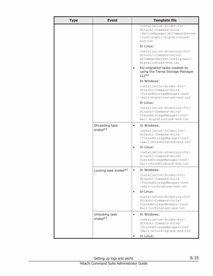
Type Event Template fileinstallation-folder-for-Hitachi-Command-Suite\DeviceManager\HiCommandServer\config\mail-migrationtask-end.txtIn Linux:installation-directory-for-Hitachi-Command-Suite/HiCommandServer/config/mail-migrationtask-end.txt
• For migration tasks created byusing the Tiered Storage ManagerCLI#2
In Windows:installation-folder-for-Hitachi-Command-Suite\TieredStorageManager\conf\mail-migrationtask-end.txtIn Linux:installation-directory-for-Hitachi-Command-Suite/TieredStorageManager/conf/mail-migrationtask-end.txt
Shredding taskended#2
• In Windows:installation-folder-for-Hitachi-Command-Suite\TieredStorageManager\conf\mail-shreddingtask-end.txt
• In Linux:installation-directory-for-Hitachi-Command-Suite/TieredStorageManager/conf/mail-shreddingtask-end.txt
Locking task ended#2 • In Windows:installation-folder-for-Hitachi-Command-Suite\TieredStorageManager\conf\mail-lockingtask-end.txt
• In Linux:installation-directory-for-Hitachi-Command-Suite/TieredStorageManager/conf/mail-lockingtask-end.txt
Unlocking taskended#2
• In Windows:installation-folder-for-Hitachi-Command-Suite\TieredStorageManager\conf\mail-unlockingtask-end.txt
• In Linux:
Setting up logs and alerts 6-15Hitachi Command Suite Administrator Guide

Type Event Template fileinstallation-directory-for-Hitachi-Command-Suite/TieredStorageManager/conf/mail-unlockingtask-end.txt
Time lapse Volume lock periodexpired#2
• In Windows:installation-folder-for-Hitachi-Command-Suite\TieredStorageManager\conf\mail-retention-term-expired.txt
• In Linux:installation-directory-for-Hitachi-Command-Suite/TieredStorageManager/conf/mail-retention-term-expired.txt
Specified timeelapsed#2
• In Windows:installation-folder-for-Hitachi-Command-Suite\TieredStorageManager\conf\mail-migrationgroup-reminder.txt
• In Linux:installation-directory-for-Hitachi-Command-Suite/TieredStorageManager/conf/mail-migrationgroup-reminder.txt
#1:The template files are stored in the following locations:
¢ In Windows:installation-folder-for-Hitachi-Command-Suite\DeviceManager\HiCommandServer\template
¢ In Linux:installation-directory-for-Hitachi-Command-Suite/HiCommandServer/template
#2:The template files are stored in the following locations:
¢ In Windows:installation-folder-for-Hitachi-Command-Suite\TieredStorageManager\template
¢ In Linux:installation-directory-for-Hitachi-Command-Suite/TieredStorageManager/template
6-16 Setting up logs and alertsHitachi Command Suite Administrator Guide

By specifying, within the template files, parameters that will automatically befilled in with event information at the time of an event, you can add usefulinformation to the email notifications.
The following shows how to create a template, using the template for theMigration task ended event (mail-migrationtask-end.txt) as an example.
Set up template files using the following format:
• Specify a header in the first line, nothing in the second line, and the emailbody in the third and following lines.
• Specify a header in the format Subject: email-title.• Specify parameters in the format ${parameter-name}.• Use UTF-8 encoding to code the template file.• The size of the template file must not exceed 64 KB.• The length of each line in the template file must not exceed 1024 bytes,
excluding linefeed characters.
Note: To apply changes to the template file, restart the Hitachi CommandSuite product services.
The parameters that can be specified in a template depend on the events.The parameters are listed in Table 6-6 Parameters for events that occur whentasks end (migration tasks created via the Migrate data wizard) on page6-17 to Table 6-8 Parameters for time-lapse events on page 6-19.
Table 6-6 Parameters for events that occur when tasks end (migrationtasks created via the Migrate data wizard)
Parameter Description
task Task name
taskType Task type
Setting up logs and alerts 6-17Hitachi Command Suite Administrator Guide

Parameter Description
status Task status
description Task description
user The user ID of the user who createdthe task.
scheduledTime Time the task execution was requested
completedTime Time the task execution ended
storageSystem Storage system name
migrationSourceHost Migration source: Host
migrationSourceLG Migration source: Logical Group
migrationSourcePool Migration source: Pool
migrationTargetTier Migration target: Tier
migrationTargetPool Migration target: Pool
options Options
migratedVolumes Volume ID of the migrated volume
Table 6-7 Parameters for events that occur when tasks end (tasks createdvia the Tiered Storage Manager CLI)
Parameter Description
taskId Task ID
taskType Task type
taskStatus Task status
taskOwner The user ID of the user who created the task.
executionRequestTime Time that task execution was requested
endTime Time that task execution ended
storageDomainName Storage domain name
migrationGroupName Migration group name
previousTargetStorageTierName Name of the target storage tier in the previousmigration
targetStorageTierName Name of the target storage tier
eraseData Whether data after migration is to be deleted
migratedVolumes Device numbers of both migrated volumes andvolumes whose data has been erased
shreddingMethod Shredding method
shreddedVolumes Device numbers of shredded volumes
guardMode Lock mode
6-18 Setting up logs and alertsHitachi Command Suite Administrator Guide

Parameter Description
retentionDays Retention period (days)
lockedVolumes Device numbers of locked volumes
unlockedVolumes Device numbers of unlocked volumes
moveToMigrationGroupName Name of the target migration group after taskcompletion
Table 6-8 Parameters for time-lapse events
Parameter Description
storageDomainName Storage domain name
migrationGroupName Migration group name
expiredVolumes Device numbers of expired volumes
remindAt Scheduled time when an "elapsed time"event will occur
reminderDescription Message that appears when an "elapsedtime" event occurs
Related topics
• Starting the Hitachi Command Suite services on page 8-4• Stopping the Hitachi Command Suite services on page 8-5• For details about the parameters of each event: Tiered Storage Manager
CLI Reference Guide
Specifying SMTP user authentication information for eventnotification
The event notification functionality establishes a connection with the SMTPserver. To use SMTP authentication for the connection, an SMTPauthentication user account must be set up in the Device Manager server byusing the hdvmmodmailuser command.
Tip: To send notifications about executed tasks via the Tiered StorageManager CLI, an SMTP authentication user account must be set up on theTiered Storage Manager server by using the htsmmodmailuser command.
Format of the hdvmmodmailuser command
The SMTP authentication user settings set by the hdvmmodmailuser commandare also used for alert email notification and health check results emailnotification. If an SMTP authentication user has already been set for alertemail notification or health check results email notification, then thesesettings are not required here.
Setting up logs and alerts 6-19Hitachi Command Suite Administrator Guide

The following is the syntax of the hdvmmodmailuser command:
Format
In Windows:installation-folder-for-Hitachi-Command-Suite\DeviceManager\HiCommandServer\tools\hdvmmodmailuser.bat -u Device-Manager-user-ID -p Device-Manager-password SMTP-authentication-user-ID[SMTP-authentication-password]
In Linux:installation-directory-for-Hitachi-Command-Suite/HiCommandServer/tools/hdvmmodmailuser.sh -u Device-Manager-user-ID -p Device-Manager-password SMTP-authentication-user-ID[SMTP-authentication-password]
Options
-u Device-Manager-user-IDSpecify the ID of a user for which All Resources has been assigned as aresource group and Admin has been set as the role in Device Manager.
-p Device-Manager-passwordSpecify the password used to log in to Device Manager by the userDevice-Manager-user-ID specified using the -u option.
SMTP-authentication-user-IDSpecify a user ID used for SMTP authentication.
SMTP-authentication-passwordSpecify a logon password for the user ID used to log on to the SMTPserver.
Caution:
• If SMTP authentication is enabled on the Device Manager server, but anSMTP authentication user is not registered, email will be sent withoutusing SMTP authentication.
• Only one SMTP authentication user can be set on the Device Managerserver. The set SMTP authentication user information will be updatedeach time you execute the command.
• You cannot delete the SMTP authentication user information that you seton the Device Manager server.
To enable the settings set by the hdvmmodmailuser command, after thehdvmmodmailuser command finishes executing, restart the Hitachi CommandSuite product services.
Related topics
• Starting the Hitachi Command Suite services on page 8-4• Stopping the Hitachi Command Suite services on page 8-5
6-20 Setting up logs and alertsHitachi Command Suite Administrator Guide

Format of the htsmmodmailuser command
Execute the command after moving to the following folder or directory:
In Windows:installation-folder-for-Hitachi-Command-Suite\TieredStorageManager\bin
In Linux:installation-directory-for-Hitachi-Command-Suite/TieredStorageManager/bin
The following shows the syntax of the htsmmodmailuser command:
Format
htsmmodmailuser -u Tiered-Storage-Manager-user-ID -p Tiered-Storage-Manager-password SMTP-authentication-user-ID SMTP-authentication-password
Options
-u Tiered-Storage-Manager-user-IDSpecify the ID of a user for whom All Resources has been assigned as aDevice Manager resource group and who has Admin permission for TieredStorage Manager.
-p Tiered-Storage-Manager-passwordSpecify a logon password for the user ID used to log on to Tiered StorageManager via the u option.
SMTP-authentication-user-IDSpecify a user ID for SMTP authentication.
SMTP-authentication-passwordSpecify a logon password for the user ID used to log on to the SMTPserver.
To enable the settings set by the htsmmodmailuser command, after thehtsmmodmailuser command finishes executing, restart the Hitachi CommandSuite product services
Caution: If the following conditions apply, execute the htsmmodmailusercommand from a shell such as tcsh or bash that supports commands thatare longer than 256 bytes:
• You are executing the htsmmodmailuser command from an instance ofTiered Storage Manager running in Linux.
• The command exceeds 256 bytes.
Related topics
• Starting the Hitachi Command Suite services on page 8-4• Stopping the Hitachi Command Suite services on page 8-5
Setting up logs and alerts 6-21Hitachi Command Suite Administrator Guide

Reporting failure information about storage systems (forVSP G1000 only)
This topic explains how to report storage system failure though Syslog oremail.
You can report failure information (SIM) about storage systems throughSyslog, SNMP trap, and email. Failure information reported through email isthe same as SIM displayed on the Alert window or reported through SNMPtrap. For SNMP trap, the user needs to access the SNMP Manager to check forfailure. However, for report through Syslog or email, the user has only tocheck Syslog or email to know about the occurrence of failure. See theHitachi SNMP Agent User Guide for methods of notification with SNMP traps.
Requirements of the new Syslog protocol (TLS1.2/RFC5424)The new Syslog protocol (TLS1.2/RFC5424) requires the following:
• Operation confirmed Syslog server (rsyslog version 4.6.2)• Syslog server certificate. The IP address of the Syslog server in "Subject
Alternative Name: IP Address" of the Syslog server certificate.• Client certificate. Upload the following:
Certificate type Format Notes
Syslog server rootcertificate
X.509 Obtain the Syslog server root certificate fromthe server administrator.
Client certificate PKCS#12 Convert the Syslog server client certificatethat is signed by a Certificate Authority (CA)to PKCS#12 format. (See Obtaining a clientcertificate for the new Syslog protocol onpage 6-22.)
Each certificate has an expiry date, after which you are prevented fromconnecting to the Syslog server. Note the expiration dates when preparingcertificates.
Contact the Syslog server administrator for the following:
• Password set up in the PKCS#12-format client certificate• More information about the certificates
Obtaining a client certificate for the new Syslog protocolTo obtain a client certificate:
1. Download the program to create the certificate from the followingwebsite: OpenSSL website, http://www.openssl.org/.
2. Install the OpenSSL program in the C:\openssl folder.3. Convert the client certificate to the PKCS#12 format.
6-22 Setting up logs and alertsHitachi Command Suite Administrator Guide

Example
The following example to obtain a client certificate, Windows Vista is theoperating system. Both a private key and a public key are created. Theclient.p12 file is the client certificate in PKCS#12 format. This file is createdin the c:\key folder.
1. Create a private key (.key file). See Creating a private key (.key file) onpage 4-85.
2. Create a public key (.csr file). See Creating a public key (.csr file) on page4-85.
3. Send the new key to the Syslog server Certificate Authority for signatureto obtain a certificate. The certificate is used as the client certificate.
When preparing a certificate, note its expiration date. If the expiration datepasses, you will not be able to connect to the Syslog server.
Setting and configuring syslog notification for SIMsYou can be notified in syslog format when storage system failures occur.
Prerequisites
• You must have the Storage Administrator (Initial Configuration) role toperform this task.
• You must have a server that supports syslogs.• If a firewall is used, a port must be opened to transfer syslogs.
To configure settings for syslog notification:
1. Click Settings > Environmental Settings > Edit Alert Settings.2. In Notification Alert, select the destination of the alert notification.
¢ Host Report: Reports alerts only to the host(s) for which SIM reportsetting is made.
¢ All: Reports alerts to all hosts.3. In Transfer Protocol, select the protocol for Syslog transfer.4. To transfer Syslog to the primary server, select Enable and set the
following items:
¢ IP Address¢ Port Number¢ Client Certificate File Name, Password, and Root Certificate File NameUse this field only when you select New Syslog Protocol (TLS1.2/RFC5424) in Transfer Protocol.
5. To transfer Syslog to the alternate server (secondary server), selectEnable and set the following items:
¢ IP Address¢ Port Number¢ Client Certificate File Name, Password, and Root Certificate File Name
Setting up logs and alerts 6-23Hitachi Command Suite Administrator Guide

Use this field only when you select New Syslog Protocol (TLS1.2/RFC5424) in Transfer Protocol.
6. Enter a name in Location Identification Name for identification for thestorage system.
7. If you select New Syslog Protocol (TLS1.2/RFC5424) in TransferProtocol, also specify timeout, retry interval, and number of retries.
8. As necessary, click Test Send to Syslog Server to test the settings.9. Check that the Syslog server has received log (Detailed data: "RefCode:
7FFFFF, This is Test Report.").10. Click Finish. The Confirm window opens.11. In the Confirm window, check the settings and enter a task name in
Task Name.12. Click Apply. The task is registered. If the Go to tasks window for
status check box is checked, the Task window opens.
Related topics
• Normal login on page 5-26
Configuring email notificationPrerequisites
• You must have a Security Administrator account with an InitialConfiguration role to perform this task.
• You must have a mail server that supports the Simple Mail TransferProtocol (SMTP).
• If a firewall is used, port 25 must be used.
To configure settings for email notices:
1. Click Settings > Environmental Settings > Edit Alert Settings. TheE-mail Information window opens.
2. In Notification Alert, select the destination of the alert notification.
¢ Host Report: Reports alerts only to the host(s) for which SIM reportsetting is made.
¢ All: Reports alerts to all hosts.Alert notification destination is common to Syslog, SNMP, and Email.
3. Select Enable in Mail Notice on the Email tab.4. In the Email Settings table, set the email destination address and
attributes (To, Cc, Bcc).
¢ To add an email address, click Add. On the Add Address window, setthe email address and attributes.
¢ To change an email address and attributes, select the line for theemail address to be changed, and click Change. In the ChangeSettings window, change the email address and attributes.
6-24 Setting up logs and alertsHitachi Command Suite Administrator Guide

You can select more than one email address. When you selected morethan one email address, you can change only attributes.
¢ To delete an email address, select the line for the email address to bedeleted and click Delete. You can select more than one emailaddress.
This field is mandatory when you select Enable in Mail Notice.5. Enter the email source address (mandatory) and return address
(optional).You can use up to 255 alphanumeric characters (ASCII codes) andsymbols (! # $ % & ` + - * / ' ^ { } _ . )
6. Enter the the following email server information:
¢ Identifier. To specify a host name, select Identifier. You can use upto 63 alphanumeric characters (ASCII codes) and symbols ("! # $ ` +- * ' { } _ . ).
¢ IPv4. To set an IPv4 address, select IPv4, and enter four numberswithin the range of 0 to 255.Example: XXX.XXX.XXX.XXX (X indicates a numeral)
¢ IPv6. To set an IPv6 address, select IPv6, and enter eighthexadecimal alphanumeric characters within the range of 0 to FFFF.You can also use an abbreviated-format IPv6 address.Example: YYYY:YYYY:YYYY:YYYY:YYYY:YYYY:YYYY:YYYY (Y indicates ahexadecimal digit)
7. In SMTP Authentication, select Enable to use SMTP authentication.Select Disable to not use SMTP authentication. If you select Enable,enter an account and password for SMTP authentication.You can use up to 255 alphanumeric characters (ASCII codes) andsymbols (! # $ % & ` + - * / ' ^ { } _ .).This field is mandatory when you selected Enable in Mail Notice.
8. If necessary, click Email Test Send to test the settings.9. Check that the test email has been received.
For a test email example and explanation, see Example of test email,below.
10. Click Finish. The Confirm window opens.11. In the Confirm window, check the settings and enter a task name in
Task Name.12. Click Apply. The task is registered. If the Go to tasks window for
status check box is checked, the Task window opens.
Example of test emailDate: FRI 25 OCT 2013 10:10:10 +9000 (JST)To: VSP G1000 [email protected]: [email protected]: [email protected]: VSP G1000 ReportDate : 25/10/2013Time : 10:09:30
Setting up logs and alerts 6-25Hitachi Command Suite Administrator Guide

Machine : VSP G1000 (Serial# 64019)RefCode : 7FFFFFDetail: This is Test Report.The field definitions in the test email are listed in the following table:
Table 6-9 Email details for system failures notice
# Item Description
1 Date Date and time when the email was sent. This time stamp is set by themail server.
2 To Email address of the receiver.
3 From Email address of the sender.
4 Reply-To Email address to which replies from the receivers will be sent. Optional.
5 Subject Email title (Name of the storage system) + (Report)
6 Date Date when a system failure occurred.
7 Time Time when a system failure occurred.
8 Machine Name and serial number of the storage system.
9 RefCode Reference code. The same code as the one reported by SNMP traps.
10 Detail Failure details. The same information as the one reported by SNMPtraps.
See the Hitachi SNMP Agent User Guide for reference codes and failuredetails.
Related topics
• Normal login on page 5-26
Setting system optionsYou can change settings about alert display and data acquisition by settingsystem options. Log off and log in again when you enabled or disabled asystem option.
Prerequisites
• You must have the Storage Administrator (Initial Configuration) role toperform this task.
To set system options:
1. Click Settings > Environmental Settings > Edit System Options.2. Select the system option to set and click Enable.
¢ Hide alert information. If you enable this system option, the Alertwindow does not open.
6-26 Setting up logs and alertsHitachi Command Suite Administrator Guide

¢ Refresh forcibly after Apply. If you enable this system option, aftersettings changes are applied to the storage system, the configurationinformation for the storage system is forcibly updated.
¢ Disable data polling. If you enable this system option, polling stops.¢ Disable retry of data updating. If you enable this system option,
retry does not occur even if data cannot be acquired.¢ Enable Device Manager - Storage Navigator 2 All Function. If
you enable this system option, the restrictions on login from DeviceManager - Storage Navigator's login window are cleared, including therestrictions on the users who can log in and on the functions availableafter login. When enabling or disabling the system option, log inagain.
3. Click Finish. The Confirm window opens.4. In the confirmation window, check the settings and enter a task name in
Task Name.5. Click Apply. The task is registered. If the Go to tasks window for
status check box is checked, the Task window opens.
Related topics
• Normal login on page 5-26
Setting up logs and alerts 6-27Hitachi Command Suite Administrator Guide

6-28 Setting up logs and alertsHitachi Command Suite Administrator Guide

7Configuring Device Manager for CIM/
WBEM
This chapter explains how to configure Device Manager for CIM/WBEM .
□ About CIM/WBEM
□ CIM/WBEM functions in Device Manager
□ Specifying a namespace
□ User account settings for using the CIM/WBEM functions
□ Enabling CIM/WBEM functions
□ Settings for acquiring storage system performance information by usingCIM/WBEM functions
□ Controlling the SLP service
Configuring Device Manager for CIM/WBEM 7-1Hitachi Command Suite Administrator Guide

About CIM/WBEMDevice Manager supports CIM and WBEM, which have been defined by theDMTF standards group. CIM is a method of managing systems in a networkenvironment. WBEM is a standard for managing network devices, such ashosts and storage systems, over the Internet.
The CIM model that Device Manager uses complies with the SMI-Sspecifications advocated by SNIA, and is compatible with SNIA-CTP. CIM/WBEM functions can be used to manage the configuration and status ofstorage systems in a standardized manner that is independent of vendor, OS,protocol, and other environmental factors.
The CIM models of the Device Manager server are defined in MOF filesprovided by Device Manager.
Figure 7-1 CIM components for Device Manager
You can acquire information about CIM at:
http://www.dmtf.org/You can acquire information about SMI-S at:
http://www.snia.org/
CIM/WBEM functions in Device ManagerThe CIM/WBEM functions in Device Manager provide the following functionsthat come standard in SMI-S:
Object operation functionThe SMI-S specifications, which Device Manager conforms to, define theinterfaces for devices that make up a storage network, such as storagesystems, virtual storage systems, switches, and hosts. The functions thatneed to be provided by the management service to manage the devicesare grouped in a profile for each device.
7-2 Configuring Device Manager for CIM/WBEMHitachi Command Suite Administrator Guide

The profiles used by the CIM/WBEM functions of Device Manager are theArray profile and its subprofiles. The Array profile defines the interfacesfor storage systems.
Indication functionThe indication function is the event notification function defined by CIM.When an event occurs in a CIM server, the CIM server reports theindication instance, which shows the information about the event (such asgeneration or deletion of a CIM instance), to CIM clients. For a CIM clientto receive indications, its location and transmission conditions forindications must be registered in the CIM server beforehand. For detailson how to register them, see the SNIA website.Device Manager reports the occurrence of the following events:
¢ Generation of a volume¢ Deletion of a volume¢ Allocation of a LUN path¢ Cancellation of a LUN path
Service discovery functionDevice Manager provides the service discovery function based on theService Location Protocol (SLP).The SLP is undergoing standardization by IETF and provides a way todiscover desired services available in a network. For details on the SLP,see RFC2608.Just by specifying the type of service, SLP clients can acquire information(such as URLs) about how to access the available services, andinformation about service attributes.In Device Manager, the Device Manager server uses the SLP to reportinformation about the WBEM Service.
Performance information acquisition functionDevice Manager acquires the following types of information as storagesystem performance information:
¢ Port-related informationTotal I/O countData traffic
¢ Volume-related informationTotal I/O countData trafficNumber of read I/OsNumber of read I/Os that hit the cacheNumber of write I/OsNumber of write I/Os that hit the cache
Configuring Device Manager for CIM/WBEM 7-3Hitachi Command Suite Administrator Guide

Specifying a namespaceDevice Manager supports versions 1.1.0 through 1.5.0 of SMI-S. Thenamespace that is used to connect to Device Manager (CIM server) must bespecified on CIM clients.
You can specify a namespace by using the follow format:
• Specify the SMI-S version.Specify root/smis/smisxx (xx is an abbreviation for the versionnumber).For example, to specify version 1.5.0, enter root/smis/smis15.The latest namespaces that complies with the specified SMI-S version isselected.
• Specify the condition current.Enter root/smis/current.The current namespace is selected.
• Specify interop.SMI-S 1.3.0 or a later version supports the namespace interop. Ifinterop is specified as the namespace, the Server profile that stores thecurrent management server information is specified.The namespace of each vendor is accessed via this Server profile toacquire information about the Array profile and its subprofiles.For interop namespaces, only the queries from SMI-S version 1.3.0 orlater can be set for the Query property of CIM_IndicationFilter.
Table 7-1 Correspondence between namespaces and SMI-S versions
NamespaceSMI-S
smisxx current interop
smis11 -- -- 1.1.0
smis12 -- -- 1.2.0
smis13 -- -- 1.3.0
smis14 -- -- 1.4.0
smis15 current interop 1.5.0
Legend: --: N/A
User account settings for using the CIM/WBEM functionsNote that All Resources must be assigned for the users who use the CIM/WBEM functions. Also note that the CIM methods that can be executed differdepending on the role in Device Manager.
7-4 Configuring Device Manager for CIM/WBEMHitachi Command Suite Administrator Guide

Table 7-2 Roles in Device Manager and CIM methods that can be executed
Role in Device ManagerCIM method that can be executed
Service methods CIM operations
Admin or Modify Y Y
View or Peer -- Y
Legend:Y: These CIM methods can be executed.--: These CIM methods cannot be executed.
Enabling CIM/WBEM functionsWhen Hitachi Command Suite has been installed as a new installation, theCIM/WBEM functions are enabled. If you want to enable the CIM/WBEMfunctions again after having disabled them, you need to specify environmentsettings as described below.
Operations to complete in advance
• Log in as a user with Administrator permissions (for Windows) or as aroot user (for Linux)
• Register the storage system in Device Manager.When registering a storage system that is to be managed, use theaccount of an administrator for the entire storage system. Do not use theaccount of an administrator who only has permissions for part of thestorage system.
• Check port numbers.Check whether any port numbers exist that are used by both the CIM/WBEM functions of Device Manager and programs other than DeviceManager. If such port numbers exist, change the port numberassignments so that the CIM/WBEM functions of Device Manager useunique port numbers.
• Set the language tag (when using the service discovery function)When starting the CIM client, set the language tag (locale) for the servicediscovery function to English (en).
To enable the CIM/WBEM functions:
1. On the Device Manager server, in the server.properties file, set theserver.cim.support property to true.
2. Restart the Hitachi Command Suite product services.When an external storage system is connected to Virtual StoragePlatform, Universal Storage Platform V/VM or Hitachi USP, if there is alarge number of LDEVs managed by Device Manager, it might take timefor the services to start.
Configuring Device Manager for CIM/WBEM 7-5Hitachi Command Suite Administrator Guide

3. Refresh the storage systems registered in Device Manager server via theDevice Manager GUI or CLI.
Caution:
• If you delete a storage system while disabling CIM/WBEM functions,perform step 3 in the following order to restart the services.1. In the server.properties file, change theserver.logicalview.initialsynchro property to true.2. Restart the Hitachi Command Suite product services.3. In the server.properties file, change theserver.logicalview.initialsynchro property back to false.
• If you use CIM/WBEM to perform an operation for resources (such asLDEVs and parity groups) that have been reserved by the setup operationfrom the Device Manager GUI, the setting might be changed or theresources might be deleted.
Related topics
• Ports used by the Device Manager server on page 2-3• Starting and stopping the SLP service on page 7-16• Starting the Hitachi Command Suite services on page 8-4• Stopping the Hitachi Command Suite services on page 8-5• server.cim.support on page A-9• server.logicalview.initialsynchro on page A-12
Changing CIM/WBEM port numbersTo change the port numbers used by CIM/WBEM functions, edit the relevantproperty files on the Device Manager server.
Operations to complete in advance
Log in as a user with Administrator permissions (for Windows) or as a rootuser (for Linux).
To change a port number:
1. Stop the services of Hitachi Command Suite product.2. Set the port numbers by editing the following Device Manager server
properties:
¢ For non-SSL communication:server.cim.http.port property in the server.properties file andHTTPPort property in the cimxmlcpa.properties file
¢ For SSL communication:server.cim.https.port property in the server.properties file andHTTPSPort property in the cimxmlscpa.properties file
7-6 Configuring Device Manager for CIM/WBEMHitachi Command Suite Administrator Guide

In the cimxmlscpa.properties file, make sure that you also set theCiphers property.
3. Start the services of Hitachi Command Suite product.
Related topics
• Starting the Hitachi Command Suite services on page 8-4• Stopping the Hitachi Command Suite services on page 8-5• server.cim.http.port on page A-10• server.cim.https.port on page A-11• Ciphers on page A-33• HTTPPort on page A-52• HTTPSPort on page A-52
Settings for acquiring storage system performanceinformation by using CIM/WBEM functions
This section describes the system configuration that is required to use theperformance information acquisition function, and how to specify settings foracquiring performance information.
Required system configuration for acquiring performanceinformation
The system configuration in which the performance information of a storagesystem is acquired by using the CIM/WBEM functions differs depending on themodel of the storage system.
Configuring Device Manager for CIM/WBEM 7-7Hitachi Command Suite Administrator Guide

Figure 7-2 Example of a system configuration in which performanceinformation of a storage system is acquired
Storage systemThis is a storage system whose performance information is to beacquired.The host that acquires performance information (the Device Manageragent) acquires the information of enterprise-class storage systems(Virtual Storage Platform, Universal Storage Platform V/VM, and HitachiUSP) by using the command device within the storage system, and thenreports it to the Device Manager server.In midrange storage systems (HUS100, Hitachi AMS2000, Hitachi SMS, orHitachi AMS/WMS), the Device Manager server acquires performanceinformation directly from a storage system.
Host that acquires performance informationThis host is required when acquiring performance information ofenterprise-class storage systems (Virtual Storage Platform, UniversalStorage Platform V/VM or Hitachi USP). Device Manager agent version 7.0or later is required for Virtual Storage Platform storage systems, andDevice Manager agent version 5.9 or later is required for UniversalStorage Platform V/VM or Hitachi USP storage systems.We recommend that use the same computer for the management serverand for the host that acquires performance information.
7-8 Configuring Device Manager for CIM/WBEMHitachi Command Suite Administrator Guide

Even if you use different computers for the management server and forthe host that acquires performance information, the OS for the host thatacquires performance information must be Windows, Solaris, or Linux.The host that acquires performance information cannot run HP-UX or AIX.We recommend that you use the hdvmagt_setting command to set theDevice Manager agent central management method.
Management serverDevice Manager server version 5.9 or later must be installed, and theCIM/WBEM functions must be enabled.
Settings required to acquire performance information of enterprise-class storage systems
This section describes the settings required to acquire performanceinformation for enterprise-class storage systems (Virtual Storage Platform,Universal Storage Platform V/VM, or Hitachi USP).
Preparing the storage system for acquiring performance information
Prepare a command device for each storage system from which you want toacquire performance information, and then assign a LUN path to the host thatwill acquire the performance information so that the host can recognize thecommand device.
To acquire Virtual Storage Platform performance information, force hosts torecognize command devices for which authentication mode is disabled.
Preparing the host to acquire performance information
Install the Device Manager agent, and then register command devices.
To collect performance information:
1. Install the Device Manager agent.To acquire performance information, a CCI/LIB is necessary. If you installthe Device Manager agent on a host, the necessary CCI/LIB is installed.However, if the host OS is UNIX, and a CCI/LIB is already installed on thehost, the CCI/LIB is not overwritten. If this is the case, install the properCCI/LIB, as shown in the following table.
Table 7-3 CCI/LIB required to acquire performance information
Storage system Version
Virtual Storage Platform 01-15-03/00 or later
Universal Storage Platform V/VM 01-12-03/03 or later
Hitachi USP 01-12-03/03 or later
2. Use the Device Manager agent hdvmagt_setting command to configurethe central management method settings. (This is recommended.)
Configuring Device Manager for CIM/WBEM 7-9Hitachi Command Suite Administrator Guide

3. Use the perf_findcmddev command to register command devices.
Caution:
• If you upgrade the Device Manager agent from version 6.3 or earlierto version 6.4 or later, the settings in the perf_cmddev.propertiesfile remain unchanged. If you are using a storage system in an SLPRenvironment, after the upgrade installation finishes, refresh theinformation of SLPR command devices defined in theperf_cmddev.properties file.
• If you are using the Device Manager agent version 6.3 or earlier andyou want to use a storage system in an SLPR environment, directlyedit the perf_cmddev.properties file to define command devices forSLPRs.
Related topics
• Defining the command device (perf_findcmddev command) on page7-10
• Setting the Device Manager server's information, HiScan command'sexecution period, and CCI's information (hdvmagt_setting command) onpage 10-20
• How to install Device Manager agent :Hitachi Command Suite Installationand Configuration Guide
Preparing the Device Manager server to acquire performance information
On the Device Manager server, in the server.properties file, set theserver.cim.agent property to the host name of the host that collectsperformance information (the host on which the Device Manager agent isinstalled).
Caution: Make sure that the host name specified for the server.cim.agentproperty matches the host name registered in Device Manager for the hostthat acquires performance information. If these host names are different, youcannot acquire performance information.
Related topics
• Changing Device Manager server properties on page A-4• server.cim.agent on page A-9
Defining the command device (perf_findcmddev command)
To register a command device on a Device Manager agent, execute theperf_findcmddev command with the write option specified.
Operations to complete in advance
Log in as a user with Administrator permissions or as a root user.
7-10 Configuring Device Manager for CIM/WBEMHitachi Command Suite Administrator Guide

Format of the command
perf_findcmddev { write [-file file-name] | verify | view }
Storage directory of the command
In Windows:installation-folder-for-the-Device-Manager-agent\bin
In Linux:installation-directory-for-the-Device-Manager-agent/bin
In Solaris:/opt/HDVM/HBaseAgent/bin
Options
write [-file file-name]This option outputs the settings of all command devices recognized by thehost to the file.You can use the -file file-name option to specify the desired file name.To specify the file name, you can use an absolute or relative path.If you do not specify the -file option, the perf_cmddev.properties filewill be overwritten.If no command device recognized by the host is detected, nothing isoutput to the perf_cmddev.properties file.
verifyThis option compares the settings for the command devices defined in theperf_cmddev.properties file to the settings for the command devicesrecognized by the host. If the host recognizes multiple command devices,the execution result is output for each.
¢ If the information of a command device defined in theperf_cmddev.properties file matches the information of thecommand device recognized by the host, the following message isdisplayed:The definition of the command device is valid.
¢ If the host does not recognize a command device defined in theperf_cmddev.properties file:The error message KAIC28615-W and information of the commanddevice that is not recognized by the host are displayed.
¢ If a command device recognized by the host is not defined in thesettings file:The error message KAIC28616-W and information of the commanddevice that is not defined in the settings file are displayed.Note that, if the settings for a command device are defined in theperf_cmddev.properties file by using the format of version 6.3 orearlier, the command device is assumed to belong to SLPR0.
Configuring Device Manager for CIM/WBEM 7-11Hitachi Command Suite Administrator Guide

viewThis parameter displays the settings for the command devices defined inthe perf_cmddev.properties file.In the perf_cmddev.properties file, UNKNOWN is displayed for any lineson which non-recognizable values are defined or that are not correctlyformatted. Comment lines and blank lines are not displayed. In addition,if no value is specified in the perf_cmddev.properties file, only theheader is displayed.The following is an example of output from the command. The items thatare output are the same as the items set in the perf_cmddev.propertiesfile.
Raid ID Serial# SLPR# LDEV# Device file nameR500 14050 0 345 \\.\PhysicalDrive3R601 44332 1 456 \\.\Volume{xxxxxxx-xxxx-xxx-xxxxxxxx}R501 UNKNOWN - 1045 \\.\PhysicalDrive10
Related topics
• Format of the perf_cmddev.properties file on page 7-12
Format of the perf_cmddev.properties file
Edit the perf_cmddev.properties file to define the command device of thetarget storage system.
Storage directory of the perf_cmddev.properties file
In Windows:installation-folder-for-the-Device-Manager-agent\mod\hdvm\config
In Linux:installation-directory-for-the-Device-Manager-agent/mod/hdvm/config
In Solaris:/opt/HDVM/HBaseAgent/mod/hdvm/config
Format of the perf_cmddev.properties file
Define one command device per line, using the following format.
When using the Device Manager agent version 6.4 or later:RAID-ID.serial-number.[SLPR-number.]LDEV-number: deviceFileName
When using the Device Manager agent version 6.3 or earlier:RAID-ID.serial-number.LDEV-number: deviceFileName
7-12 Configuring Device Manager for CIM/WBEMHitachi Command Suite Administrator Guide

Table 7-4 Settings in the perf_cmddev.properties file
Setting item Value
RAID-ID Specify one of the following depending on the type of thetarget storage system:R700 for Virtual Storage Platform
R600 for Universal Storage Platform V
R601 for Universal Storage Platform VM
R500 for Hitachi USP
R501 for Hitachi NSC55
Serial-number Specify the serial number of the storage system by usinga decimal (base 10) number.
SLPR-number Specify the number of the SLPR to which the commanddevice belongs by using a decimal (base 10) number. Ifno SLPR is configured, specify 0.This item is optional. If you omit this item or define thisitem by using the format for version 6.3 or earlier, it isassumed that no SLPR has been configured.
LDEV-number Specify the CU:LDEV number of the command device byusing a decimal (base 10) number.
deviceFileName Specify the command device identifier (the PhysicalDrivenumber, VolumeGUID, or device file name) that the hostrecognizes in the following format:#
• In Windows:\\.\PhysicalDriveX\\.\Volume{GUID}
• In Solaris:/dev/rdsk/cxtxdxs2
• In Linux:/dev/sdx
x is an integer.
#:
• If this item is specified using the physical drive number in Windows orLinux and you then restart the OS, the physical drive number and devicefile name might be changed. If this occurs, you need to execute theperf_findcmddev command to check and update the settings. InWindows, if you specify this item using the volume GUID, the setting isnot affected even if you restart the OS.
• If you are using the Device Manager agent version 6.3 or earlier and youwant to acquire performance information of all SLPRs in an SLPRenvironment, you need to define SLPR0 command device in theperf_cmddev.properties file.To define command devices for different SLPRs that belong to the samestorage system, define the SLPR0 command device in the first line of thestorage system. The following example shows how to define
Configuring Device Manager for CIM/WBEM 7-13Hitachi Command Suite Administrator Guide

PhysicalDrive5 (whose LDEV number is 345) as the SLPR0 commanddevice of Hitachi USP (whose serial number is 14050).
R600.44332.456: \\.\PhysicalDrive3R500.14050.345: \\.\PhysicalDrive5R500.14050.346: \\.\PhysicalDrive6R500.14050.347: \\.\PhysicalDrive10R501.89832.780: \\.\PhysicalDrive15
Settings required to acquire performance information of midrangestorage systems
This section describes the settings required to acquire performanceinformation from midrange storage systems (HUS100, Hitachi AMS2000,Hitachi SMS, or Hitachi AMS/WMS).
Preparing the storage system
Before you use the function for acquiring performance information, you needto use Element Manager in the Device Manager GUI, Storage NavigatorModular, or Storage Navigator Modular 2 to specify the settings for acquiringperformance statistics for each relevant storage system.
Related topics
• How to specify the settings for collecting performance statistics: Themanual for each storage system
Setting up a user account to acquire performance information(hdvmmodpolluser command)
If account authentication or password protection is enabled in a storagesystem, the storage system might be locked while performance information isbeing acquired. If the storage system is locked, other users cannot log in.
If account authentication is enabled, you can prevent the storage systemfrom being locked during acquisition of performance information byregistering the user account that is used to acquire performance informationin both the storage system and Device Manager.
To register the user account that is used to acquire performance informationin Device Manager, execute the hdvmmodpolluser command.
You can register only one user account in Device Manager. If you execute thehdvmmodpolluser command with another user account specified, thepreviously registered information will be overwritten.
Operations to complete in advance
• Register a user account that has only the read permission for eachstorage system
7-14 Configuring Device Manager for CIM/WBEMHitachi Command Suite Administrator Guide
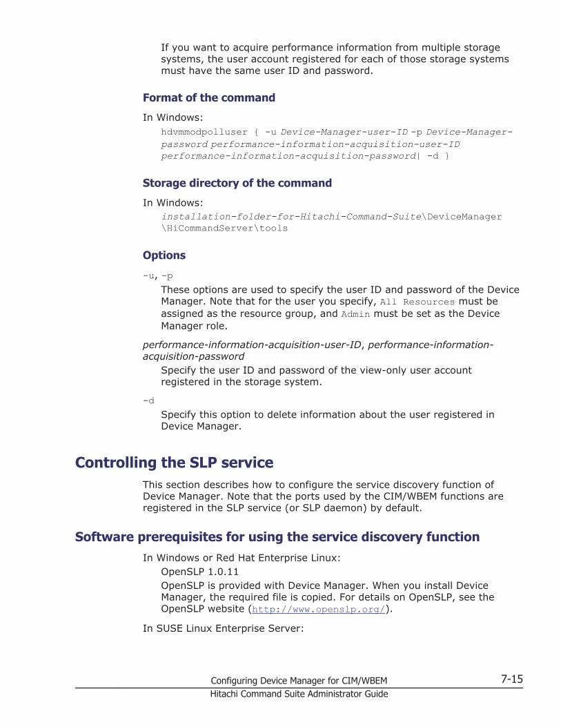
If you want to acquire performance information from multiple storagesystems, the user account registered for each of those storage systemsmust have the same user ID and password.
Format of the command
In Windows:hdvmmodpolluser { -u Device-Manager-user-ID -p Device-Manager-password performance-information-acquisition-user-IDperformance-information-acquisition-password| -d }
Storage directory of the command
In Windows:installation-folder-for-Hitachi-Command-Suite\DeviceManager\HiCommandServer\tools
Options
-u, -pThese options are used to specify the user ID and password of the DeviceManager. Note that for the user you specify, All Resources must beassigned as the resource group, and Admin must be set as the DeviceManager role.
performance-information-acquisition-user-ID, performance-information-acquisition-password
Specify the user ID and password of the view-only user accountregistered in the storage system.
-dSpecify this option to delete information about the user registered inDevice Manager.
Controlling the SLP serviceThis section describes how to configure the service discovery function ofDevice Manager. Note that the ports used by the CIM/WBEM functions areregistered in the SLP service (or SLP daemon) by default.
Software prerequisites for using the service discovery functionIn Windows or Red Hat Enterprise Linux:
OpenSLP 1.0.11OpenSLP is provided with Device Manager. When you install DeviceManager, the required file is copied. For details on OpenSLP, see theOpenSLP website (http://www.openslp.org/).
In SUSE Linux Enterprise Server:
Configuring Device Manager for CIM/WBEM 7-15Hitachi Command Suite Administrator Guide

OpenSLP 1.2.0OpenSLP is provided with the SUSE Linux Enterprise Server system. Fordetails on OpenSLP, see the Novell website (http://www.novell.com/).
Starting and stopping the SLP serviceThis section describes how to start and stop the SLP service.
Starting and stopping the SLP service (Windows)
Operations to complete in advance
Log in as a user with Administrator permissions.
To start the SLP service:
1. Perform either of the following procedures:
¢ From Administrative Tools, select Services and then ServiceLocation Protocol to start the SLP service.
¢ Show the command prompt, move to the folder containing theOpenSLP executable file, and execute the following command:
slpd -start
To stop the SLP service:
1. Perform either of the following procedures:
¢ From Administrative Tools, select Services and then ServiceLocation Protocol.
¢ Display the command prompt, move to the folder containing theOpenSLP executable file, and execute the following command:
slpd -stop
Starting and stopping the SLP daemon (Red Hat Enterprise Linux)
Operations to complete in advance
Log in as a user with root user.
To start the SLP daemon:
1. Execute the following command:
installation-directory-for-Hitachi-Command-Suite/HiCommandServer/wsi/bin/slpd.sh start
To stop the SLP daemon:
1. Execute the following command:
7-16 Configuring Device Manager for CIM/WBEMHitachi Command Suite Administrator Guide

installation-directory-for-Hitachi-Command-Suite/HiCommandServer/wsi/bin/slpd.sh stop
Starting and stopping the SLP daemon (SUSE Linux Enterprise Server)
Operations to complete in advance
Log in as a user with root user.
To start the SLP daemon:
1. Execute the following command:
# /usr/sbin/rcslpd start
To stop the SLP daemon:
1. Execute the following command:
# /usr/sbin/rcslpd stop
Releasing the SLP serviceYou might need to release the SLP service (or SLP daemon) when uninstallingHitachi Command Suite products.
If the following message is displayed, manually release the SLP service fromthe Windows services.
Unable to release the SLP service, but the removal will continue. After the removal, release the SLP service.
Releasing the SLP service (Windows)
Operations to complete in advance
Log in as a user with Administrator permissions.
To release the SLP service:
1. Show the command prompt and move to the folder containing theOpenSLP executable file.
2. Execute the following command:
slpd -remove
Configuring Device Manager for CIM/WBEM 7-17Hitachi Command Suite Administrator Guide

Releasing the SLP daemon (Linux)
Operations to complete in advance
Log in as a user with root user.
To release the SLP daemon:
1. Stop the SLP daemon.2. If /etc/init.d/slpd exists, delete it.
# chkconfig --level 01345 slpd off# chkconfig --del slpd# rm -f /etc/init.d/slpd
Notes on OpenSLP logsSince the SLP service log output (or SLP daemon) accumulates as timeelapses, if you use the SLP service (or SLP daemon) for an extended period oftime, the log output might eventually use up a lot of disk space. To preventthis, you need to periodically back up the log file and clear the disk space. Bydefault, only the start message at SLP daemon startup is output to the logfile.
In Windows:%WINDIR%slpd.log%WINDIR% is replaced by the value of the environment variable WINDIRin Windows. Normally, the value is C:\WINNT\.
In Linux:installation-directory-for-Hitachi-Command-Suite/HiCommandServer/wsi/cfg/slp.log
7-18 Configuring Device Manager for CIM/WBEMHitachi Command Suite Administrator Guide

8Starting and stopping services
This chapter explains how to start and stop the Hitachi Command Suiteproduct services.
□ Starting and stopping services of Hitachi Command Suite
□ Starting and stopping services of the Host Data Collector
Starting and stopping services 8-1Hitachi Command Suite Administrator Guide

Starting and stopping services of Hitachi Command SuiteThis section explains how to start and stop the services of Device Manager,Tiered Storage Manager, and Replication Manager.
Resident processes of Hitachi Command SuiteHitachi Command Suite (Device Manager, Tiered Storage Manager, andReplication Manager) operation requires that resident processes are runningon the OS.
The following table describes the resident processes of Device Manager,Tiered Storage Manager, and Replication Manager.
Table 8-1 Resident processes in Windows
Process name Service name Function
htsmService.exe HiCommand TieredStorage Manager
The Tiered Storage Manager server
HiCommandServer HiCommandServer The Device Manager server
hcmdssvctl.execjstartweb.exe
HBase 64 StorageMgmt CommonService
Hitachi Command Suite servlet service.If the Device Manager server and otherHitachi Command Suite products areinstalled on the same computer, a processof a service other than HBase 64 StorageMgmt Common Service might be startedby using the name hcmdssvctl.exe andcjstartweb.exe.
hcmdssvctl.execjstartweb.exe
HBase 64 StorageMgmt SSO Service
Hitachi Command Suite servlet service forsingle sign-on
httpsd.exerotatelogs.exe
HBase 64 StorageMgmt Web Service
Hitachi Command Suite common webservice.Multiple instances of this process might berunning.
httpsd.exerotatelogs.exe
HBase 64 StorageMgmt Web SSOService
Hitachi Command Suite common webservice for single sign-on.
hcmdssvctl.execjstartweb.exe
HCS DeviceManager WebService
Device Manager servlet service
hntr2mon.exe Hitachi NetworkObjectplazaTrace Monitor 2Hitachi NetworkObjectplazaTrace Monitor 2(x64)
Hitachi Command Suite common trace logcollection
hntr2srv.exe Hitachi Command Suite common traceservice (This service processes eventsfrom the Services window.)
8-2 Starting and stopping servicesHitachi Command Suite Administrator Guide

Process name Service name Function
pdservice.exe# HiRDB/EmbeddedEdition_HD1
HiRDB process server control
#:This process must always be running. Do not stop it manually or registerit as a cluster resource.
Table 8-2 Resident processes in Linux
Process name Function
htsmservice The Tiered Storage Manager server
hicmdserver The Device Manager serverinstallation-directory-for-Hitachi-Command-Suite/HiCommandServer/hicmdserver
hcs_ssocjstartweb
Hitachi Command Suite servlet service/bin/sh installation-directory-for-Hitachi-Command-Suite/Base64/uCPSB/CC/web/containers/HiCommand64/hcs_ssoinstallation-directory-for-Hitachi-Command-Suite/Base64/uCPSB/CC/web/bin/cjstartweb
hcs_hssocjstartweb
Hitachi Command Suite servlet service for single sign-oninstallation-directory-for-Hitachi-Command-Suite/Base64/uCPSB/CC/web/containers/HBase64StgMgmtSSOService/hcs_hssoinstallation-directory-for-Hitachi-Command-Suite/Base64/uCPSB/CC/web/bin/cjstartweb
httpsdrotatelogs
Hitachi Command Suite common web serviceMultiple instances of this process might be running.installation-directory-for-Hitachi-Command-Suite/Base64/uCPSB/httpsd/sbin/httpsdinstallation-directory-for-Hitachi-Command-Suite/Base64/uCPSB/httpsd/sbin/rotatelogs
httpsdrotatelogs
Hitachi Command Suite common web service for singlesign-on.installation-directory-for-Hitachi-Command-Suite/Base64/uCPSB/httpsd/sbin/httpsdinstallation-directory-for-Hitachi-Command-Suite/Base64/uCPSB/httpsd/sbin/rotatelogs
hcs_dmcjstartweb
Device Manager servlet service/bin/sh installation-directory-for-Hitachi-Command-Suite/Base64/uCPSB/CC/web/containers/DeviceManagerWebService/hcs_dminstallation-directory-for-Hitachi-Command-Suite/Base64/uCPSB/CC/web/bin/cjstartweb
Starting and stopping services 8-3Hitachi Command Suite Administrator Guide

Process name Function
/opt/hitachi/HNTRLib2/bin/hntr2mon
Hitachi Command Suite common trace log collection
pdprcd# HiRDB process server process
#:This process must always be running. Do not stop it manually or registerit as a cluster resource.
Related topics
• Starting the Hitachi Command Suite services on page 8-4• Stopping the Hitachi Command Suite services on page 8-5• Checking the operating status of the Hitachi Command Suite services on
page 8-7• Resident processes of the Host Data Collector on page 8-8
Starting the Hitachi Command Suite servicesYou can start the Hitachi Command Suite services from the Windows menu orby using the hcmds64srv command.
Operations to complete in advance
Log in as a user with Administrator permissions (for Windows) or as a rootuser (for Linux).
To start the services:
1. Perform the following operations.
In Windows:Start the services in either of the following ways:In Windows Server 2008 R2Select Start, All Programs, Hitachi Command Suite, ManageServices, and then Start - HCS.In Windows Server 2012 or Windows Server 2012 R2From the Start window, open the application list window, selectHitachi Command Suite, and then Start - HCS.By using the following command:installation-folder-for-Hitachi-Command-Suite\Base64\bin\hcmds64srv /start
In Linux:Execute the following command:installation-directory-for-Hitachi-Command-Suite/Base64/bin/hcmds64srv -start
8-4 Starting and stopping servicesHitachi Command Suite Administrator Guide

The following services are started in a batch, and the results of starting theservices are displayed in the window:
• HiRDB• HBase 64 Storage Mgmt Common Service• HBase 64 Storage Mgmt SSO Service• HBase 64 Storage Mgmt Web Service• HBase 64 Storage Mgmt Web SSO Service• HCS Device Manager Web Service• HiCommandServer• HiCommand Tiered Storage Manager• All Hitachi Command Suite product services present on the same server
Note: If the system is linked with Hitachi File Services Manager or StorageNavigator Modular 2 and you use a command to start Hitachi Command Suiteproduct services, also execute the following commands:
• In Windows:installation-folder-for-Hitachi-File-Services-Manager-or-Storage-Navigator-Modular-2\Base\bin\hcmdssrv /start
• In Linux:installation-directory-for-Hitachi-File-Services-Manager-or-Storage-Navigator-Modular-2/Base/bin/hcmdssrv -start
Tip: The Storage Navigator Modular 2 service does not start even if HitachiCommand Suite product services start.To start the Storage Navigator Modular 2 service:
In Windows:Perform either of the following operations:- From the Services window, select SNM2 Server, and then Restart theservice.- From the command prompt, execute the following command:net start snm2server
In Linux:Log in as a root user, and then execute the following command:/etc/init.d/snm2srv start
Stopping the Hitachi Command Suite servicesYou can stop the Hitachi Command Suite services from the Windows menu orby using the hcmds64srv command.
Operations to complete in advance
Log in as a user with Administrator permissions (for Windows) or as a rootuser (for Linux).
Starting and stopping services 8-5Hitachi Command Suite Administrator Guide
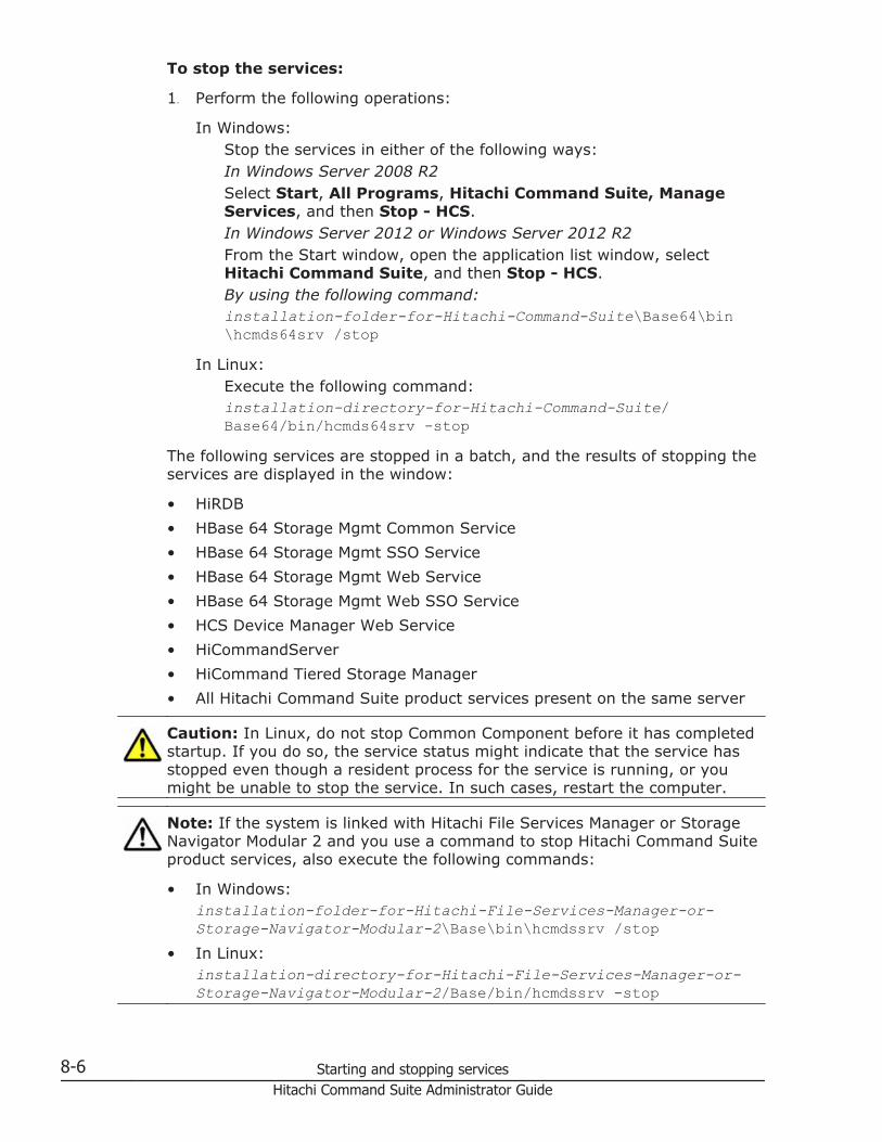
To stop the services:
1. Perform the following operations:
In Windows:Stop the services in either of the following ways:In Windows Server 2008 R2Select Start, All Programs, Hitachi Command Suite, ManageServices, and then Stop - HCS.In Windows Server 2012 or Windows Server 2012 R2From the Start window, open the application list window, selectHitachi Command Suite, and then Stop - HCS.By using the following command:installation-folder-for-Hitachi-Command-Suite\Base64\bin\hcmds64srv /stop
In Linux:Execute the following command:installation-directory-for-Hitachi-Command-Suite/Base64/bin/hcmds64srv -stop
The following services are stopped in a batch, and the results of stopping theservices are displayed in the window:
• HiRDB• HBase 64 Storage Mgmt Common Service• HBase 64 Storage Mgmt SSO Service• HBase 64 Storage Mgmt Web Service• HBase 64 Storage Mgmt Web SSO Service• HCS Device Manager Web Service• HiCommandServer• HiCommand Tiered Storage Manager• All Hitachi Command Suite product services present on the same server
Caution: In Linux, do not stop Common Component before it has completedstartup. If you do so, the service status might indicate that the service hasstopped even though a resident process for the service is running, or youmight be unable to stop the service. In such cases, restart the computer.
Note: If the system is linked with Hitachi File Services Manager or StorageNavigator Modular 2 and you use a command to stop Hitachi Command Suiteproduct services, also execute the following commands:
• In Windows:installation-folder-for-Hitachi-File-Services-Manager-or-Storage-Navigator-Modular-2\Base\bin\hcmdssrv /stop
• In Linux:installation-directory-for-Hitachi-File-Services-Manager-or-Storage-Navigator-Modular-2/Base/bin/hcmdssrv -stop
8-6 Starting and stopping servicesHitachi Command Suite Administrator Guide

Tip: The Storage Navigator Modular 2 service does not stop even if HitachiCommand Suite product services stop.To stop the Storage Navigator Modular 2 service:
In Windows:Perform either of the following operations:- From the Services window, select SNM2 Server, and then Stop theservice.- From the command prompt, execute the following command:net stop snm2server
In Linux:Log in as a root user, and then execute the following command:/etc/init.d/snm2srv stop
Checking the operating status of the Hitachi Command Suite servicesYou can check the operating status of the Hitachi Command Suite servicesfrom the Windows menu or by using the hcmds64srv command.
Operations to complete in advance
Log in as a user with Administrator permissions (for Windows) or as a rootuser (for Linux).
To check the operating status of the services:
1. Perform the following operations:
In Windows:Check the operating status of the services in either of the followingways:In Windows Server 2008 R2Select Start, All Programs, Hitachi Command Suite, ManageServices, and then Status - HCS.In Windows Server 2012 or Windows Server 2012 R2From the Start window, open the application list window, selectHitachi Command Suite, and then Status - HCS.By using the following command:installation-folder-for-Hitachi-Command-Suite\Base64\bin\hcmds64srv /statusall
In Linux:Execute the following command:installation-directory-for-Hitachi-Command-Suite/Base64/bin/hcmds64srv -statusall
The operating status of the services are displayed in the window.
Starting and stopping services 8-7Hitachi Command Suite Administrator Guide

Starting and stopping services of the Host Data CollectorThis section explains how to start and stop the Host Data Collector services.
Resident processes of the Host Data CollectorThe resident processes of the Host Data Collector are Host Data Collectorservice process and JavaVM service process.
These processes are listed in Table 8-3 Resident processes of the Host DataCollector (Windows) on page 8-8 to Table 8-4 Resident processes of theHost Data Collector (Linux) on page 8-8.
Table 8-3 Resident processes of the Host Data Collector (Windows)
Process name Service name Function
HdcProcessController.exe Host Data Collector BaseService
Host Data Collectorservice
Table 8-4 Resident processes of the Host Data Collector (Linux)
Process name Function
installation-directory-for-Host-Data-Collector/HDC/Base/internal/bin/HdcAdapter.sh
Adapter process of the HostData Collector service#
installation-directory-for-Host-Data-Collector/HDC/Base/internal/bin/HdcService.sh
Service process of the Host DataCollector service
installation-directory-for-Host-Data-Collector/HDC/Base/internal/bin/HdcRMI.sh
RMI process of the Host DataCollector service
Java-execution-environment-installation-path/bin/java
JavaVM (Adapter)#
Java-execution-environment-installation-path/bin/java
JavaVM (Service)
Java-execution-environment-installation-path/bin/java
JavaVM (RMI)
#:There are as many resident Adapter processes as the value specified forthe hdc.adapter.adapterProcessNum property in thehdcbase.properties file for Host Data Collector.
Note: In a cluster configuration, while the Host Data Collector service on theexecuting node is running, the Host Data Collector service on the standbynode must also be active.
Related topics
• Resident processes of Hitachi Command Suite on page 8-2
8-8 Starting and stopping servicesHitachi Command Suite Administrator Guide

Starting the Host Data Collector serviceUse the controlservice command to start the Host Data Collector service.
Operations to complete in advance
Log in as a user with Administrator permissions (for Windows) or as a rootuser (for Linux).
To start the Host Data Collector service:
1. Execute the following command:
In Windows:installation-folder-for-Host-Data-Collector\HDC\Base\bin\controlservice.exe start
In Linux:installation-directory-for-Host-Data-Collector/HDC/Base/bin/controlservice.sh start
Related topics
• Resident processes of the Host Data Collector on page 8-8• Stopping the Host Data Collector service on page 8-9• Checking the operating status of the Host Data Collector service on page
8-10
Stopping the Host Data Collector serviceUse the controlservice command to stop the Host Data Collector service.
Operations to complete in advance
Log in as a user with Administrator permissions (for Windows) or as a rootuser (for Linux).
To stop the Host Data Collector service:
1. Execute the following command:
In Windows:installation-folder-for-Host-Data-Collector\HDC\Base\bin\controlservice.exe stop
In Linux:installation-directory-for-Host-Data-Collector/HDC/Base/bin/controlservice.sh stop
Related topics
• Resident processes of the Host Data Collector on page 8-8• Starting the Host Data Collector service on page 8-9
Starting and stopping services 8-9Hitachi Command Suite Administrator Guide

• Checking the operating status of the Host Data Collector service on page8-10
Checking the operating status of the Host Data Collector serviceUse the controlservice command to check the operating status of the HostData Collector service.
Operations to complete in advance
Log in as a user with Administrator permissions (for Windows) or as a rootuser (for Linux).
To check the operating status of the Host Data Collector service:
1. Execute the following command:
In Windows:installation-folder-for-Host-Data-Collector\HDC\Base\bin\controlservice.exe state
In Linux:installation-directory-for-Host-Data-Collector/HDC/Base/bin/controlservice.sh state
Related topics
• Resident processes of the Host Data Collector on page 8-8• Starting the Host Data Collector service on page 8-9• Stopping the Host Data Collector service on page 8-9
8-10 Starting and stopping servicesHitachi Command Suite Administrator Guide

9Managing the database
This chapter describes how to back up and restore the database for HitachiCommand Suite products.
□ Managing databases
□ Backing up databases
□ Restoring databases
□ Migrating databases
Managing the database 9-1Hitachi Command Suite Administrator Guide

Managing databasesThe following table describes backing up and restoring, as opposed toexporting and importing.
Table 9-1 Backing up and restoring as opposed to exporting and importing
Item Backing up and restoring Exporting and importing
Restrictions onHitachi CommandSuite productversions
No restrictions Products of version 05-50 or latermust be installed on the server towhich data is imported or fromwhich data is exported.
Main purpose To restore the currentoperating environment if afailure occurs on the server
To migrate the server data from thecurrent environment to a differentenvironment (such as a server thathas a different OS)
Target data • Databases for HitachiCommand Suite products
• The Common Componentdatabase
• Databases for HitachiCommand Suite products
• User information in theCommon Component database
Conditions forcomputers
• The installed HitachiCommand Suite productsare the same between thebackup-source computerand the restoration-destination computer.
• The version and revisionof the installed HitachiCommand Suite productsare the same between thebackup-source computerand the restoration-destination computer.
• The Hitachi Command Suiteproducts to be imported areinstalled on the import-destination computer.
• The versions and revisions ofthe Hitachi Command Suiteproducts installed on theimport-destination server arethe same as or later than theversions and revisions of theproducts installed on theexport-source computer.
The following sections describe the procedure for each operation separately.
Backing up databasesIf an error occurs in the database, the management server might not be ableto be used. As a preparatory measure, therefore, back up the databaseregularly.
To back up a database, a directory for storing backup files is required. Thisdirectory requires space equal to the formula below. In addition to theestimate below, space is required for the temporary files created duringbackup.
Required space:(total-size-of-all-Hitachi-Command-Suite-product-databases-to-be-backed-up + 4.6 GB) x 2
9-2 Managing the databaseHitachi Command Suite Administrator Guide

As an example, in an environment in which Device Manager, Tiered StorageManager, and Replication Manager are used, estimate the required space bytaking into consideration the sizes of the following directories:
• The directory of the Device Manager database• The directory of the Tiered Storage Manager database• The directory of the Replication Manager database• The directories of the Common Component database#
#: As the directories of Common Component database, the BASE directoryand the SYS directory exist.
If other Hitachi Command Suite products are used, add the sizes of theproduct directories to the estimate.
Caution:
• If Tuning Manager is remotely connected, stop the Tuning Managerservices on the computer where the Tuning Manager server is installed.After the database is backed up, restart the Tuning Manager services. Fordetails about how to start and stop the Tuning Manager services, see themanual for the installed version of Tuning Manager.
• During database backup, Hitachi Command Suite services stop.Therefore, do not access Hitachi Command Suite while the backup is inprogress.
Note: If you access a database-related file used by Hitachi Command Suiteproducts by using the backup software, an error might occur due to an I/Odelay or file exclusion.If you want to perform a backup that includes the Hitachi Command Suiteinstallation directory by using the backup software, stop all the services ofHitachi Command Suite products, and then perform the backup.
Backing up a database in non-cluster configurationTo back up a database when management servers are not clustered, performthe procedure below.
To back up a database:
1. Log on to the management server as a user with Administratorpermissions or root permissions.
2. Execute the hcmds64backups command to back up the database.
In Windows:installation-folder-for-Hitachi-Command-Suite\Base64\bin\hcmds64backups /dir folder-for-storing-backup-files /auto
In Linux:installation-directory-for-Hitachi-Command-Suite/Base64/bin/hcmds64backups -dir directory-for-storing-backup-files -auto
Managing the database 9-3Hitachi Command Suite Administrator Guide

dirSpecify the absolute path of the directory on the local disk in whichthe database backup files are stored. In Linux, do not specify a paththat includes a space.Make sure that no files or subdirectories are in the directory specifiedfor the dir option.
autoAutomatically starts or stops Hitachi Command Suite services.
When you execute the hcmds64backups command, the directorydatabase will be created in the directory for storing backup files, specifiedwith the dir option, and these files will be combined and stored as the filebackup.hdb.
Note: The setting files for Hitachi Command Suite products are backed upin locations other than the database directory created in the directory forstoring backup files, specified with the dir option. If an error occurs inthe management server and you need to re-install Hitachi CommandSuite products, you can use the backed up setting files to check theprevious settings.
Backing up a database in a cluster configurationTo back up a database when Windows management servers are clustered,perform the procedure below.
Caution: Use the executing node (a machine that has online set for mode inthe cluster.conf file) to make backups of databases.
To back up a database:
1. Log on to the management server as a user with Administratorpermissions.
2. Use the cluster management application to select the following services,and then from the right-click menu, take the services offline:
¢ HiCommand Tiered Storage Manager¢ HiCommandServer¢ HCS Device Manager Web Service¢ HBase 64 Storage Mgmt Web Service¢ HBase 64 Storage Mgmt Common Service¢ Hitachi Command Suite product resources other than the above
3. Execute the hcmds64srv /stop command to stop the Hitachi CommandSuite product services.Then, execute the hcmds64srv /statusall command to make sure thatthe services have stopped or that the return code of the command is 0.
4. Use the cluster management application to take the following serviceoffline:
9-4 Managing the databaseHitachi Command Suite Administrator Guide

¢ HiRDBClusterService _HD15. Use the cluster management application to suppress failover of the
resource group.Change the settings of the resources listed below.
¢ HiCommand Tiered Storage Manager¢ HiCommandServer¢ HCS Device Manager Web Service¢ HBase 64 Storage Mgmt Web Service¢ HBase 64 Storage Mgmt Common Service¢ HiRDBClusterService _HD1¢ Hitachi Command Suite product resources other than the aboveRight-click the resource name, and select Properties, the Policies tab,and then If resource fails, do not restart.
6. Execute the hcmds64backups command to back up the database.installation-folder-for-Hitachi-Command-Suite\Base64\bin\hcmds64backups /dir folder-for-storing-backup-files /autodir
Specify the absolute path of the directory on the shared disk in whichthe database backup files are stored.Make sure that no files or subfolders are in the directory specified forthe dir option.
autoAutomatically starts or stops Hitachi Command Suite services.
When you execute the hcmds64backups command, the directorydatabase will be created in the directory for storing backup files, specifiedwith the dir option, and these files will be combined and stored as the filebackup.hdb.
7. Execute the hcmds64srv /stop command to stop the Hitachi CommandSuite product services.Then, execute the hcmds64srv /statusall command to make sure thatthe services have stopped or that the return code of the command is 0.
8. Use the cluster management application to enable failover of the resourcegroup.Change the settings of the resources listed below.
¢ HiCommand Tiered Storage Manager¢ HiCommandServer¢ HCS Device Manager Web Service¢ HBase 64 Storage Mgmt Web Service¢ HBase 64 Storage Mgmt Common Service¢ HiRDBClusterService _HD1¢ Hitachi Command Suite product resources other than the above
Managing the database 9-5Hitachi Command Suite Administrator Guide

Right-click the resource name, select Properties, the Policies tab, andthen the following items:
¢ If resource fails, attempt restart on current node¢ If restart is unsuccessful, fail over all resources in this Role (or
If restart unsuccessful, fail over all resources in this service orapplication)
9. In the cluster management application, bring online the resource group inwhich the Hitachi Command Suite product services are registered.
Related topics
• Starting the Hitachi Command Suite services on page 8-4• Stopping the Hitachi Command Suite services on page 8-5
Restoring databasesIf an error occurs with a database, use the following methods, depending onthe situation, to restore the database:
• When a database inconsistency occurs:The database can be restored by using a database that has been backedup via the hcmds64backups command.All of the following must be same between the management server whenthe database was backed up and the management server when thedatabase is restored:
¢ Type, version, and revision of the installed Hitachi Command Suiteproducts
¢ Installation destination of the Hitachi Command Suite products¢ Installation destination of Common Component¢ Installation destination of the Hitachi Command Suite product
databases¢ Installation destination of the Common Component database¢ IP address and host name of the computer
• When a database is corrupted:The database can be restored by using a database exported via thehcmds64dbtrans command.The type, version, and revision of the installed Hitachi Command Suiteproducts must be the same between the management server when thedatabase was exported and the management server when the database isrestored.When the hcmds64dbrepair command is executed, all of the HitachiCommand Suite databases installed on the management server areforcibly deleted and then replaced by the exported databases.
9-6 Managing the databaseHitachi Command Suite Administrator Guide

Restoring a database when a data inconsistency occurs in a non-cluster configuration
To restore a database when management servers are not clustered, performthe procedure below.
Caution:
• The hcmds64db command, which is used in the procedure below, createstemporary files during execution. Make sure that the directory to whichthe backup file is to be restored satisfies the following conditions:- The write permission is granted to the user who executes the hcmds64dbcommand.- There is enough free capacity for the stored backup file.
• If Tuning Manager is remotely connected, stop the Tuning Managerservices on the computer where the Tuning Manager server is installed.After the database is restored, restart the Tuning Manager services. Fordetails about how to start and stop the Tuning Manager services, see themanual for the installed version of Tuning Manager.
• During database restoration, Hitachi Command Suite services stop.Therefore, do not access Hitachi Command Suite while restoration is inprogress.
To restore a database:
1. Log on to the management server as a user with Administratorpermissions or root permissions.
2. Execute the hcmds64db command to restore the database.
In Windows:installation-folder-for-Hitachi-Command-Suite\Base64\bin\hcmds64db /restore backup-file /type name-of-the-Hitachi-Command-Suite-product-to-be-restored /auto
In Linux:installation-directory-for-Hitachi-Command-Suite/Base64/bin/hcmds64db -restore backup-file -type name-of-the-Hitachi-Command-Suite-product-to-be-restored -auto
restoreSpecify the absolute path to the database backup file (backup.hdb)that was created by using the hcmds64backups command. In Linux,do not specify a path that includes a space.
typeAs a rule, specify ALL. If you specify ALL, the databases of all HitachiCommand Suite products that are installed on the management serverare restored at once.To restore the database of only a specific Hitachi Command Suiteproduct because of a failure or other reasons, specify the name of theproduct to be restored as listed in the following table.
Managing the database 9-7Hitachi Command Suite Administrator Guide
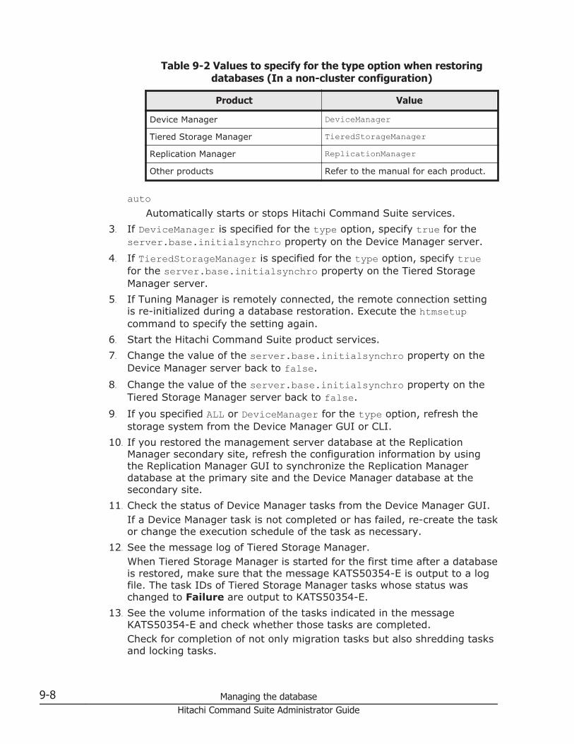
Table 9-2 Values to specify for the type option when restoringdatabases (In a non-cluster configuration)
Product Value
Device Manager DeviceManager
Tiered Storage Manager TieredStorageManager
Replication Manager ReplicationManager
Other products Refer to the manual for each product.
autoAutomatically starts or stops Hitachi Command Suite services.
3. If DeviceManager is specified for the type option, specify true for theserver.base.initialsynchro property on the Device Manager server.
4. If TieredStorageManager is specified for the type option, specify truefor the server.base.initialsynchro property on the Tiered StorageManager server.
5. If Tuning Manager is remotely connected, the remote connection settingis re-initialized during a database restoration. Execute the htmsetupcommand to specify the setting again.
6. Start the Hitachi Command Suite product services.7. Change the value of the server.base.initialsynchro property on the
Device Manager server back to false.8. Change the value of the server.base.initialsynchro property on the
Tiered Storage Manager server back to false.9. If you specified ALL or DeviceManager for the type option, refresh the
storage system from the Device Manager GUI or CLI.10. If you restored the management server database at the Replication
Manager secondary site, refresh the configuration information by usingthe Replication Manager GUI to synchronize the Replication Managerdatabase at the primary site and the Device Manager database at thesecondary site.
11. Check the status of Device Manager tasks from the Device Manager GUI.If a Device Manager task is not completed or has failed, re-create the taskor change the execution schedule of the task as necessary.
12. See the message log of Tiered Storage Manager.When Tiered Storage Manager is started for the first time after a databaseis restored, make sure that the message KATS50354-E is output to a logfile. The task IDs of Tiered Storage Manager tasks whose status waschanged to Failure are output to KATS50354-E.
13. See the volume information of the tasks indicated in the messageKATS50354-E and check whether those tasks are completed.Check for completion of not only migration tasks but also shredding tasksand locking tasks.
9-8 Managing the databaseHitachi Command Suite Administrator Guide

14. If a Tiered Storage Manager task is not completed, create and executethe task again as necessary.
Related topics
• Specifying the settings for remote connection to the Tuning Managerserver and the port number (htmsetup command) on page 5-18
• Starting the Hitachi Command Suite services on page 8-4
Restoring a database when a data inconsistency occurs in a clusterconfiguration
To restore a database when Windows management servers are clustered,perform the procedure below.
Caution:
• Use the executing node (a machine that has online set for mode in thecluster.conf file) to restore databases.
• The hcmds64db command, which is used in the procedure below, createstemporary files during execution. Make sure that the directory to whichthe backup file is to be restored satisfies the following conditions:- The write permission is granted to the user who executes the hcmds64dbcommand.- There is enough free capacity for the stored backup file.
• If Tuning Manager is remotely connected, stop the Tuning Managerservices on the computer where the Tuning Manager server is installed.After the database is restored, restart the Tuning Manager services. Fordetails about how to start and stop the Tuning Manager services, see themanual for the installed version of Tuning Manager.
• During database restoration, Hitachi Command Suite services stop.Therefore, do not access Hitachi Command Suite while restoration is inprogress.
To restore a database:
1. Log on to the management server as a user with Administratorpermissions.
2. Use the cluster management application to select the following services,and then from the right-click menu, take the services offline:
¢ HiCommand Tiered Storage Manager¢ HiCommandServer¢ HCS Device Manager Web Service¢ HBase 64 Storage Mgmt Web Service¢ HBase 64 Storage Mgmt Common Service¢ Hitachi Command Suite product resources other than the above
Managing the database 9-9Hitachi Command Suite Administrator Guide

3. Execute the hcmds64srv command to stop the Hitachi Command Suiteproduct services.
4. Use the cluster management application to take the following servicesoffline:
¢ HiRDBClusterService _HD15. Use the cluster management application to suppress failover of the
resource group.Change the settings of the resources listed below.
¢ HiCommand Tiered Storage Manager¢ HiCommandServer¢ HCS Device Manager Web Service¢ HBase 64 Storage Mgmt Web Service¢ HBase 64 Storage Mgmt Common Service¢ HiRDBClusterService _HD1¢ Hitachi Command Suite product resources other than the aboveRight-click the resource name, and select Properties, the Policies tab,and then If resource fails, do not restart.
6. Execute the hcmds64db command to restore the database.installation-folder-for-Hitachi-Command-Suite\Base64\bin\hcmds64db /restore backup-file /type name-of-the-Hitachi-Command-Suite-product-to-be-restored
restoreSpecify the absolute path to the database backup file (backup.hdb)that was created by using the hcmds64backups command. Use abackup file saved on the shared disk.
typeAs a rule, specify ALL. If you specify ALL, the databases of all HitachiCommand Suite products that are installed on the management serverare restored at once.To restore the database of only a specific Hitachi Command Suiteproduct because of a failure or other reasons, specify the name of theproduct to be restored as listed in the following table.
Table 9-3 Values to specify for the type option when restoringdatabases (For a cluster configuration)
Product Value
Device Manager DeviceManager
Tiered Storage Manager TieredStorageManager
Replication Manager ReplicationManager
Other products Refer to the manual for each product.
9-10 Managing the databaseHitachi Command Suite Administrator Guide

7. If you specified DeviceManager for the type option, set theserver.base.initialsynchro property of the Device Manager server totrue on the executing node and the standby node.
8. If you specified TieredStorageManager for the type option, set theserver.base.initialsynchro property of the Tiered Storage Managerserver to true on the executing node and the standby node.
9. Use the cluster management application to enable failover of the resourcegroup.Change the settings of the resources listed below.
¢ HiCommand Tiered Storage Manager¢ HiCommandServer¢ HCS Device Manager Web Service¢ HBase 64 Storage Mgmt Web Service¢ HBase 64 Storage Mgmt Common Service¢ HiRDBClusterService _HD1¢ Hitachi Command Suite product resources other than the aboveRight-click the resource name, select Properties, the Policies tab, andthen the following items:
¢ If resource fails, attempt restart on current node¢ If restart is unsuccessful, fail over all resources in this Role (or
If restart unsuccessful, fail over all resources in this service orapplication)
10. In the cluster management application, bring online the resource group inwhich the Hitachi Command Suite product services are registered.
11. On the executing node and standby node, change the value of theserver.base.initialsynchro property on the Device Manager serverback to false.
12. On the executing node and standby node, change the value of theserver.base.initialsynchro property on the Tiered Storage Managerserver back to false.
13. If you specified ALL or DeviceManager for the type option, refresh thestorage system from the Device Manager GUI or CLI.
14. If you restored the management server database at the ReplicationManager secondary site, refresh the configuration information by usingthe Replication Manager GUI to synchronize the Replication Managerdatabase at the primary site and the Device Manager database at thesecondary site.
15. Check the status of Device Manager tasks from the Device Manager GUI.If a Device Manager task is not completed or has failed, re-create the taskor change the execution schedule of the task as necessary.
16. See the message log of Tiered Storage Manager.When Tiered Storage Manager is started for the first time after a databaseis restored, make sure that the message KATS50354-E is output to a log
Managing the database 9-11Hitachi Command Suite Administrator Guide

file. The task IDs of Tiered Storage Manager tasks whose status waschanged to Failure are output to KATS50354-E.
17. See the volume information of the tasks indicated in the messageKATS50354-E and check whether those tasks are completed.Check for completion of not only migration tasks but also shredding tasksand locking tasks.
18. If a Tiered Storage Manager task is not completed, create and executethe task again as necessary.
19. If Tuning Manager is remotely connected, the remote connection settingis re-initialized during a database restoration. Specify the setting again.Specify the remote connection setting with Tuning Manager again byfollowing Remote connection to the Tuning Manager server (in a clusterenvironment) on page 5-15.
Related topics
• Stopping the Hitachi Command Suite services on page 8-5
Restoring a database when it is corrupted in a non-clusterconfiguration
To restore a database when management servers are not clustered, performthe procedure below.
Caution:
• If Tuning Manager is remotely connected, stop the Tuning Managerservices on the computer where the Tuning Manager server is installed.After the database is restored, restart the Tuning Manager services. Fordetails about how to start and stop the Tuning Manager services, see themanual for the installed version of Tuning Manager.
• During database restoration, Hitachi Command Suite services stop.Therefore, do not access Hitachi Command Suite while restoration is inprogress.
To restore a database:
1. Log on to the management server as a user with Administratorpermissions or root permissions.
2. Stop the Hitachi Command Suite product services.3. Execute the hcmds64dbrepair command to restore the database.
In Windows:installation-folder-for-Hitachi-Command-Suite\Base64\bin\hcmds64dbrepair /trans exported-file
In Linux:installation-directory-for-Hitachi-Command-Suite/Base64/bin/hcmds64dbrepair -trans exported-file
9-12 Managing the databaseHitachi Command Suite Administrator Guide

transSpecify the absolute path to the archive file of the database exportedvia the hcmds64dbtrans command. In Linux, do not specify a paththat includes a space.
4. Specify true for the server.base.initialsynchro property on theDevice Manager server.
5. Specify true for the server.base.initialsynchro property on theTiered Storage Manager server.
6. If Tuning Manager is remotely connected, the remote connection settingis re-initialized during a database restoration. Execute the htmsetupcommand to specify the setting again.
7. Start the Hitachi Command Suite product services.8. Change the value of the server.base.initialsynchro property on the
Device Manager server back to false.9. Change the value of the server.base.initialsynchro property on the
Tiered Storage Manager server back to false.10. Refresh the storage system from the Device Manager GUI or CLI.11. If you restored the management server database at the Replication
Manager secondary site, refresh the configuration information by usingthe Replication Manager GUI to synchronize the Replication Managerdatabase at the primary site and the Device Manager database at thesecondary site.
12. Check the status of Device Manager tasks from the Device Manager GUI.If a Device Manager task is not completed or has failed, re-create the taskor change the execution schedule of the task as necessary.
13. See the message log of Tiered Storage Manager.When Tiered Storage Manager is started for the first time after a databaseis restored, make sure that the message KATS50354-E is output to a logfile. The task IDs of Tiered Storage Manager tasks whose status waschanged to Failure are output to KATS50354-E.
14. See the volume information of the tasks indicated in the messageKATS50354-E and check whether those tasks are completed.Check for completion of not only migration tasks but also shredding tasksand locking tasks.
15. If a Tiered Storage Manager task is not completed, create and executethe task again as necessary.
16. The password for the System account is re-initialized during a databaserestoration. If necessary, specify the password again.
Related topics
• Specifying the settings for remote connection to the Tuning Managerserver and the port number (htmsetup command) on page 5-18
• Starting the Hitachi Command Suite services on page 8-4• Stopping the Hitachi Command Suite services on page 8-5
Managing the database 9-13Hitachi Command Suite Administrator Guide

• How to change the password for the System account: Hitachi CommandSuite User Guide
Restoring a database when it is corrupted in a cluster configurationTo restore a database when Windows management servers are clustered,perform the procedure below.
Caution:
• Use the executing node (a machine that has online set for mode in thecluster.conf file) to restore databases.
• If Tuning Manager is remotely connected, stop the Tuning Managerservices on the computer where the Tuning Manager server is installed.After the database is restored, restart the Tuning Manager services. Fordetails about how to start and stop the Tuning Manager services, see themanual for the installed version of Tuning Manager.
• During database restoration, Hitachi Command Suite services stop.Therefore, do not access Hitachi Command Suite while restoration is inprogress.
To restore a database:
1. Log on to the management server as a user with Administratorpermissions.
2. Use the cluster management application to select the following services,and then from the right-click menu, take the services offline:
¢ HiCommand Tiered Storage Manager¢ HiCommandServer¢ HCS Device Manager Web Service¢ HBase 64 Storage Mgmt Web Service¢ HBase 64 Storage Mgmt Common Service¢ Hitachi Command Suite product resources other than the above
3. Execute the hcmds64srv command to stop the Hitachi Command Suiteproduct services.
4. Use the cluster management application to take the following servicesoffline:
¢ HiRDBClusterService _HD15. Use the cluster management application to suppress failover of the
resource group.Change the settings of the resources listed below.
¢ HiCommand Tiered Storage Manager¢ HiCommandServer¢ HCS Device Manager Web Service¢ HBase 64 Storage Mgmt Web Service
9-14 Managing the databaseHitachi Command Suite Administrator Guide

¢ HBase 64 Storage Mgmt Common Service¢ HiRDBClusterService _HD1¢ Hitachi Command Suite product resources other than the aboveRight-click the resource name, and select Properties, the Policies tab,and then If resource fails, do not restart.
6. Execute the hcmds64dbrepair command to restore the database.installation-folder-for-Hitachi-Command-Suite\Base64\bin\hcmds64dbrepair /trans exported-filetrans
Specify the absolute path to the archive file of the database exportedvia the hcmds64dbtrans command.
7. On the executing node and standby node, specify true for theserver.base.initialsynchro property on the Device Manager server.
8. On the executing node and standby node, specify true for theserver.base.initialsynchro property on the Tiered Storage Managerserver.
9. Use the cluster management application to enable failover of the resourcegroup.Change the settings of the resources listed below.
¢ HiCommand Tiered Storage Manager¢ HiCommandServer¢ HCS Device Manager Web Service¢ HBase 64 Storage Mgmt Web Service¢ HBase 64 Storage Mgmt Common Service¢ HiRDBClusterService _HD1¢ Hitachi Command Suite product resources other than the aboveRight-click the resource name, select Properties, the Policies tab, andthen the following items:
¢ If resource fails, attempt restart on current node¢ If restart is unsuccessful, fail over all resources in this Role (or
If restart unsuccessful, fail over all resources in this service orapplication)
10. In the cluster management application, bring online the resource group inwhich the Hitachi Command Suite product services are registered.
11. On the executing node and standby node, change the value of theserver.base.initialsynchro property on the Device Manager serverback to false.
12. On the executing node and standby node, change the value of theserver.base.initialsynchro property on the Tiered Storage Managerserver back to false.
13. Refresh the storage system from the Device Manager GUI or CLI.
Managing the database 9-15Hitachi Command Suite Administrator Guide

14. If you restored the management server database at the ReplicationManager secondary site, refresh the configuration information by usingthe Replication Manager GUI to synchronize the Replication Managerdatabase at the primary site and the Device Manager database at thesecondary site.
15. Check the status of Device Manager tasks from the Device Manager GUI.If a Device Manager task is not completed or has failed, re-create the taskor change the execution schedule of the task as necessary.
16. See the message log of Tiered Storage Manager.When Tiered Storage Manager is started for the first time after a databaseis restored, make sure that the message KATS50354-E is output to a logfile. The task IDs of Tiered Storage Manager tasks whose status waschanged to Failure are output to KATS50354-E.
17. See the volume information of the tasks indicated in the messageKATS50354-E and check whether those tasks are completed.Check for completion of not only migration tasks but also shredding tasksand locking tasks.
18. If a Tiered Storage Manager task is not completed, create and executethe task again as necessary.
19. If Tuning Manager is remotely connected, the remote connection settingis re-initialized during a database restoration. Specify the setting again.Specify the remote connection setting with Tuning Manager again byfollowing Remote connection to the Tuning Manager server (in a clusterenvironment) on page 5-15.
20. The password for the System account is re-initialized during a databaserestoration. If necessary, specify the password again.
Related topics
• Stopping the Hitachi Command Suite services on page 8-5• How to change the password for the System account: Hitachi Command
Suite User Guide
Migrating databasesIf you use Hitachi Command Suite products for an extended period of time,you might need a higher performance computer to run an upgraded productor to handle an increased number of managed objects. In such a case, youhave to migrate the current databases to your new computer.
You can migrate Hitachi Command Suite product databases by using thehcmds64dbtrans command. This command migrates both the data stored inthe databases of Hitachi Command Suite products and the user informationmanaged by Common Component.
You can also use the hcmds64dbtrans command to migrate a database to aserver whose environment differs from the current one. There are thefollowing three cases:
9-16 Managing the databaseHitachi Command Suite Administrator Guide

• Migration to a server of a different platform• Migration to a server on which installation locations for Hitachi Command
Suite products differ from the ones on the migration source server• Migration to a server on which versions of Hitachi Command Suite
products are later than the ones on the migration source server
Note: If you are using the Replication tab, note that when you move themanagement server environment to a new machine, you must perform theprocedure for handing over the collected performance information. If you donot perform the procedure correctly, the collected performance informationmight be lost. For details, see Hitachi Command Suite Release Notes.
Prerequisites and restrictions on migrating databasesThe following are notes on the databases, product types, versions, and userinformation of Hitachi Command Suite products on the migration source anddestination servers.
Notes on databases, product types, and versions of Hitachi Command Suiteproducts:
¢ If the following products are installed on the migration source server,before exporting the database, upgrade the products to version 6.0 orlater on both the migration source and destination servers:Replication Monitor 5.x or earlierTuning Manager 5.x or earlierIf these products cannot be upgraded to version 6.0 or later or ifmigrating the database is not required, remove these products fromthe products whose databases are to be imported.
¢ The following restrictions apply when migrating the Tuning Managerdatabase.Specify the same capacity for the Tuning Manager database on boththe migration source and destination servers. For details about how tochange the capacity of the database, see the Tuning Manager ServerAdministration Guide.The database can be migrated if the database configuration (Small orMedium) is the same on both the migration source and destinationservers, or if the database configuration on the migration destinationserver is larger than that on the source server.On the migration source server, if the number of managed resourcesexceeds 70% of the number of manageable resources, the databasedata cannot be migrated to a database that has the sameconfiguration.
¢ If Global Link Manager is installed on the migration sourcemanagement server, remove it from the products whose databasesare to be imported. If you need it to be migrated, migrate thedatabase by following the manual that corresponds to the version ofGlobal Link Manager that is installed on the migration destinationserver.
Managing the database 9-17Hitachi Command Suite Administrator Guide

¢ Databases that are exported from an environment where DeviceManager 6.x or earlier is installed can be imported to an environmentwhere Device Manager 7.0 or later is installed. This can be done justonce, only after Device Manager 7.0 or later is newly installed. Afterthe product is installed and overwritten to version 7.0 or later or whenoperation has started on the migration destination server, do notimport the database of 6.x or earlier again.
Notes on user information:
¢ If there is user information on the migration destination server, thisuser information will be replaced with the user information from themigration source server. Therefore, do not perform a migration to aserver on which user information for Hitachi Command Suite productsalready exists.
¢ Do not migrate the databases of Hitachi Command Suite products thatwere running on different management servers to one managementserver because user information will be overwritten.
Procedure for migrating databasesTo migrate databases:
1. On the migration destination server, install the Hitachi Command Suiteproducts whose databases will be migrated.
2. Export the databases from the migration source server by using thehcmds64dbtrans command.
3. Transfer the archive file from the source server to the destination server.4. Import the databases into the destination server by using the
hcmds64dbtrans command.
The following sections describe each step.
Installing Hitachi Command Suite products on the migrationdestination server
On the migration destination server, install the Hitachi Command Suiteproducts whose databases will be migrated. Databases of Hitachi CommandSuite products that do not exist on the migration destination server cannot bemigrated. Install necessary products on the migration destination serverbefore migration.
The versions of the Hitachi Command Suite products installed on themigration destination server must be the same as or later than the ones onthe migration source server. If any of the versions of the Hitachi CommandSuite products installed on the migration destination server are earlier thanthe ones on the migration source server, no databases can be migrated.
9-18 Managing the databaseHitachi Command Suite Administrator Guide

Exporting databases on the migration source server (for a non-cluster configuration)
This section explains how to export the databases from the migration sourceserver when the OS of the management server is not in a clusterconfiguration.
To export the databases of Hitachi Command Suite products, a directory fortemporarily storing the database data and a directory for storing archive filesare required. For each directory, ensure that a comparable capacity to thetotal size of the following directories is available.
• Storage directory of each database for the installed Hitachi CommandSuite products
• Storage directory of the Common Component database (excluding theSYS directory and its subdirectories)
Caution:
• Databases are exported as archive files. If the total capacity of databasesexceeds 2 GB, creation of the archive file fails when the database data isexported. In this case, instead of using the archive file, transfer theexported database data to the migration destination.
• If Tuning Manager is remotely connected, stop the Tuning Managerservices on the computer where the Tuning Manager server is installed.After the database is exported, restart the Tuning Manager services. Fordetails about how to start and stop the Tuning Manager services, see themanual for the installed version of Tuning Manager.
• During database export, Hitachi Command Suite services stop. Therefore,do not access Hitachi Command Suite while the export is in progress.
To export databases:
1. Log on to the management server as a user with Administratorpermissions or root permissions.
2. Execute the hcmds64dbtrans command to export the databases.
In Windows:installation-folder-for-Hitachi-Command-Suite\Base64\bin\hcmds64dbtrans /export /workpath working-folder /filearchive-file /auto
In Linux:installation-directory-for-Hitachi-Command-Suite/Base64/bin/hcmds64dbtrans -export -workpath working-directory -file archive-file -auto
workpathSpecify the absolute path to the working directory where you want totemporarily store database data. In Linux, do not specify a path thatincludes a space. Specify a directory on your local disk.Make sure that no files or subdirectories are in the directory specifiedfor the workpath option.
Managing the database 9-19Hitachi Command Suite Administrator Guide

fileUsing an absolute path, specify the name of the archive file to beoutput. In Linux, do not include a space in this path.
autoAutomatically starts or stops Hitachi Command Suite services.
3. Transfer the exported files to the migration destination server.If the archive file cannot be created, transfer all the files created in thedirectory specified by the workpath option. In this case, do not changethe structure of the files.
Exporting databases on the migration source server (for a clusterconfiguration)
This section explains how to export the databases on the migration sourceserver when the OS of the management server is in a Windows clusterconfiguration.
To export the databases of Hitachi Command Suite products, a directory fortemporarily storing the database data and a directory for storing archive filesare required. For each directory, ensure that a comparable capacity to thetotal size of the following directories is available.
• Storage directory of each database for the installed Hitachi CommandSuite products
• Storage directory of the Common Component database (excluding theSYS directory and its subdirectories)
Caution:
• Use the executing node (a machine that has online set for mode in thecluster.conffile) to export databases.
• Databases are exported as archive files. If the total capacity of databasesexceeds 2 GB, creation of the archive file fails when the database data isexported. In this case, instead of using the archive file, transfer theexported database data to the migration destination.
• If Tuning Manager is remotely connected, stop the Tuning Managerservices on the computer where the Tuning Manager server is installed.After the database is exported, restart the Tuning Manager services. Fordetails about how to start and stop the Tuning Manager services, see themanual for the installed version of Tuning Manager.
• During database export, Hitachi Command Suite services stop. Therefore,do not access Hitachi Command Suite while the export is in progress.
To export databases:
1. Log on to the management server as a user with Administratorpermissions.
2. Use the cluster management application to select the following services,and then from the right-click menu, take the services offline:
9-20 Managing the databaseHitachi Command Suite Administrator Guide

¢ HiCommand Tiered Storage Manager¢ HiCommandServer¢ HCS Device Manager Web Service¢ HBase 64 Storage Mgmt Web Service¢ HBase 64 Storage Mgmt Common Service¢ Hitachi Command Suite product resources other than the above
3. Execute the hcmds64srv command to stop the Hitachi Command Suiteproduct services.
4. Use the cluster management application to take the following serviceoffline:
¢ HiRDBClusterService _HD15. Use the cluster management application to suppress failover of the
resource group.Change the settings of the resources listed below.
¢ HiCommand Tiered Storage Manager¢ HiCommandServer¢ HCS Device Manager Web Service¢ HBase 64 Storage Mgmt Web Service¢ HBase 64 Storage Mgmt Common Service¢ HiRDBClusterService _HD1¢ Hitachi Command Suite product resources other than the aboveRight-click the resource name, and select Properties, the Policies tab,and then If resource fails, do not restart.
6. Execute the hcmds64srv command to start the Hitachi Command Suiteproduct services.
7. Execute the hcmds64dbtrans command to export the databases.installation-folder-for-Hitachi-Command-Suite\Base64\bin\hcmds64dbtrans /export /workpath working-folder /filearchive-file
workpathSpecify the absolute path to the working folder where you want totemporarily store database data. Specify a folder on your local disk.Make sure that no files or subfolders are in the folder specified for theworkpath option.
fileUsing an absolute path, specify the name of the archive file to beoutput.
8. Transfer the exported files to the migration destination server.If the archive file cannot be created, transfer all the files created in thefolder specified by the workpath option. In this case, do not change thestructure of the files.
Managing the database 9-21Hitachi Command Suite Administrator Guide

9. Execute the hcmds64srv command to stop the Hitachi Command Suiteproduct services.
10. Use the cluster management application to enable failover of the resourcegroup.Change the settings of the resources listed below.
¢ HiCommand Tiered Storage Manager¢ HiCommandServer¢ HCS Device Manager Web Service¢ HBase 64 Storage Mgmt Web Service¢ HBase 64 Storage Mgmt Common Service¢ HiRDBClusterService _HD1¢ Hitachi Command Suite product resources other than the aboveRight-click the resource name, select Properties, the Policies tab, andthen the following items:
¢ If resource fails, attempt restart on current node¢ If restart is unsuccessful, fail over all resources in this Role (or
If restart unsuccessful, fail over all resources in this service orapplication)
11. In the cluster management application, bring online the resource group inwhich the Hitachi Command Suite product services are registered.
Related topics
• Starting the Hitachi Command Suite services on page 8-4• Stopping the Hitachi Command Suite services on page 8-5
Importing databases on the migration destination server (for a non-cluster configuration)
This section explains how to import the databases on the migrationdestination server when the OS of the management server is not in a clusterconfiguration.
Caution:
• If Tuning Manager is remotely connected, stop the Tuning Managerservices on the computer where the Tuning Manager server is installed.After the database is imported, restart the Tuning Manager services. Fordetails about how to start and stop the Tuning Manager services, see themanual for the installed version of Tuning Manager.
• During database import, Hitachi Command Suite services stop. Therefore,do not access Hitachi Command Suite while the import is in progress.
To import databases:
1. Log on to the management server as a user with Administratorpermissions or root permissions.
9-22 Managing the databaseHitachi Command Suite Administrator Guide

2. If you specified a value other than the default value for a property on themigration source management server, check and review the propertyvalue set on the migration destination server as required.The property file will not be migrated to the migration destination servereven if the database is imported.
3. Execute the hcmds64dbtrans command to import the databases.
In Windows:installation-folder-for-Hitachi-Command-Suite\Base64\bin\hcmds64dbtrans /import /workpath working-folder [/filearchive-file] /type {ALL|Hitachi-Command-Suite-products-whose-databases-will-be-migrated} /auto
In Linux:installation-directory-for-Hitachi-Command-Suite/Base64/bin/hcmds64dbtrans -import -workpath working-directory [-file archive-file] -type {ALL|Hitachi-Command-Suite-products-whose-databases-will-be-migrated} -auto
workpathWhen using the archive file for the import:Specify the absolute path to the directory used to extract the archivefile. In Linux, do not specify a path that includes a space. Specify adirectory on your local disk. If you want to use the archive file, thefile option must be specified.Make sure that no files or subdirectories are in the directory specifiedfor the workpath option.When not using the archive file for the import:Specify the directory that stores the database data files transferredfrom the migration source server. Do not change the structure ofthose files in the transferred directory. Also, do not specify the fileoption.
fileSpecify the absolute path to the archive file of the databasestransferred from the migration source server. In Linux, do not specifya path that includes a space. If the database data files transferredfrom the migration source server are stored in the directory specifiedby workpath, you do not need to specify this option.
typeAs a rule, specify ALL. If you specify ALL, the databases of HitachiCommand Suite products that are installed on the migrationdestination server are automatically selected and migrated.When migrating the database of only a specific Hitachi CommandSuite product because of the difference in program configurations ofmanagement servers, specify the name of the product to be migratedas listed in the following table. To specify multiple product names, usea comma to separate the names.
Managing the database 9-23Hitachi Command Suite Administrator Guide

You can use the type option to migrate databases only if the databasedata of all the specified products is contained in the archive file or inthe directory specified by the workpath option, and all the specifiedproducts exist on the migration destination server. If any of theproducts do not meet the above conditions, data cannot be migrated.
Table 9-4 Values to specify for the type option when migratingdatabases (In a non-cluster configuration)
Product Value
Device Manager#1#2 DeviceManager
Tiered Storage Manager#1 TieredStorageManager
Replication Manager#2 ReplicationManager
Other products Refer to the manual for each product.
#1: When importing databases that were exported from anenvironment of version 7.0 or later, regardless of whether you haveregistered a Tiered Storage Manager license, import both the DeviceManager and Tiered Storage Manager databases at the same time.#2: To import the Replication Manager database, you must alsoimport the Device Manager database at the same time.
autoAutomatically starts or stops Hitachi Command Suite services.
4. Specify true for the server.base.initialsynchro property on theDevice Manager server.Because, other than user information, the hcmds64dbtrans commanddoes not migrate the Common Component repository, you need tosynchronize the repository information with the imported Device Managerdatabase data.
5. Specify true for the server.base.initialsynchro property on theTiered Storage Manager server.
6. If Tuning Manager is remotely connected, the remote connection settingis re-initialized during a database import. Execute the htmsetup commandto specify the setting again.
7. Start the Hitachi Command Suite product services on the migrationdestination server as follows.
8. Change the value of the server.base.initialsynchro property on theDevice Manager server back to false.
9. Change the value of the server.base.initialsynchro property on theTiered Storage Manager server back to false.
10. In the following cases, use the Device Manager GUI or CLI to refresh thestorage systems:
¢ If the configuration of the storage system was changed between thetime databases were exported and the time they were imported:
9-24 Managing the databaseHitachi Command Suite Administrator Guide

Refresh the storage system whose configuration was changed.¢ If the versions of Hitachi Command Suite products that are installed
on the migration source and destination management servers aredifferent:Refresh all the storage systems that are registered in Device Manager.
11. If you imported the management server database at the ReplicationManager secondary site, refresh the configuration information by usingthe Replication Manager GUI to synchronize the Replication Managerdatabase at the primary site and the Device Manager database at thesecondary site.
12. Back up the databases.After resuming operations, you cannot import the archive file that wasexported in version 6.4 or earlier. In preparation for a failure, werecommend that you back up the databases immediately after importingthem.
Related topics
• Specifying the settings for remote connection to the Tuning Managerserver and the port number (htmsetup command) on page 5-18
• Starting the Hitachi Command Suite services on page 8-4• Backing up a database in non-cluster configuration on page 9-3
Importing databases on the migration destination server (for acluster configuration)
This section explains how to import the databases on the migrationdestination server when the OS of the management server is in a Windowscluster configuration.
Caution:
• Use the executing node (a machine that has online set for mode in thecluster.conf file) to import databases.
• If Tuning Manager is remotely connected, stop the Tuning Managerservices on the computer where the Tuning Manager server is installed.After the database is imported, restart the Tuning Manager services. Fordetails about how to start and stop the Tuning Manager services, see themanual for the installed version of Tuning Manager.
• During database import, Hitachi Command Suite services stop. Therefore,do not access Hitachi Command Suite while the import is in progress.
To import databases:
1. Log on to the management server as a user with Administratorpermissions.
2. If you specified a value other than the default value for a property on themigration source management server, check and review the property
Managing the database 9-25Hitachi Command Suite Administrator Guide

value set on the executing node and standby node of the migrationdestination server as required.The property file will not be migrated to the migration destination servereven if the database is imported.
3. Use the cluster management application to select the following services,and then from the right-click menu, take the services offline:
¢ HiCommand Tiered Storage Manager¢ HiCommandServer¢ HCS Device Manager Web Service¢ HBase 64 Storage Mgmt Web Service¢ HBase 64 Storage Mgmt Common Service¢ Hitachi Command Suite product resources other than the above
4. Execute the hcmds64srv command to stop the Hitachi Command Suiteproduct services.
5. Use the cluster management application to take the following servicesoffline:
¢ HiRDBClusterService _HD16. Use the cluster management application to suppress failover of the
resource group.Change the settings of the resources listed below.
¢ HiCommand Tiered Storage Manager¢ HiCommandServer¢ HCS Device Manager Web Service¢ HBase 64 Storage Mgmt Web Service¢ HBase 64 Storage Mgmt Common Service¢ HiRDBClusterService _HD1¢ Hitachi Command Suite product resources other than the aboveRight-click the resource name, and select Properties, the Policies tab,and then If resource fails, do not restart.
7. Start HiRDB.installation-folder-for-Hitachi-Command-Suite\Base64\bin\hcmds64dbsrv /start
8. Execute the hcmds64dbtrans command to import the databases.installation-folder-for-Hitachi-Command-Suite\Base64\bin\hcmds64dbtrans /import /workpath working-folder [/filearchive-file] /type {ALL|Hitachi-Command-Suite-products-whose-databases-will-be-migrated}workpath
When using the archive file for the import:Specify the absolute path to the folder used to extract the archive file.Specify a folder on your local disk. If you want to use the archive file,the file option must be specified.
9-26 Managing the databaseHitachi Command Suite Administrator Guide

Make sure that no files or subdirectories are in the folder specified forthe workpath option.When not using the archive file for the import:Specify the folder that stores the database data files transferred fromthe migration source server. Do not change the structure of those filesin the transferred directory. Also, do not specify the file option.
fileSpecify the absolute path to the archive file of the databasestransferred from the migration source server. If the database datafiles transferred from the migration source server are stored in thefolder specified by workpath, you do not need to specify this option.
typeAs a rule, specify ALL. If you specify ALL, the databases of HitachiCommand Suite products that are installed on the migrationdestination server are automatically selected and migrated.When migrating the database of only a specific Hitachi CommandSuite product because of the difference in program configurations ofmanagement servers, specify the name of the product to be migratedas listed in the following table. To specify multiple product names, usea comma to separate the names.You can use the type option to migrate databases only if the databasedata of all the specified products is contained in the archive file or inthe folder specified by the workpath option, and all the specifiedproducts exist on the migration destination server. If any of theproducts do not meet the above conditions, data cannot be migrated.
Table 9-5 Values to specify for the type option when migratingdatabases (For a cluster configuration)
Product Value
Device Manager#1#2 DeviceManager
Tiered Storage Manager#1 TieredStorageManager
Replication Manager#2 ReplicationManager
Other products Refer to the manual for each product.
#1: When importing databases that were exported from anenvironment of version 7.0 or later, regardless of whether you haveregistered a Tiered Storage Manager license, import both the DeviceManager and Tiered Storage Manager databases at the same time.#2: To import the Replication Manager database, you must alsoimport the Device Manager database at the same time.
9. On the executing node and standby node, specify true for theserver.base.initialsynchro property of the Device Manager server.Because, other than user information, the hcmds64dbtrans commanddoes not migrate the Common Component repository, you need to
Managing the database 9-27Hitachi Command Suite Administrator Guide

synchronize the repository information with the imported Device Managerdatabase data.
10. On the executing node and standby node, specify true for theserver.base.initialsynchro of the Tiered Storage Manager server.
11. Execute the hcmds64srv command to start the Hitachi Command Suiteproduct services.
12. Use the cluster management application to enable failover of the resourcegroup. Change the settings of the resources listed below.
¢ HiCommand Tiered Storage Manager¢ HiCommandServer¢ HCS Device Manager Web Service¢ HBase 64 Storage Mgmt Web Service¢ HBase 64 Storage Mgmt Common Service¢ HiRDBClusterService _HD1¢ Hitachi Command Suite product resources other than the aboveRight-click the resource name, select Properties, the Policies tab, andthen the following items:
¢ If resource fails, attempt restart on current node¢ If restart is unsuccessful, fail over all resources in this Role (or
If restart unsuccessful, fail over all resources in this service orapplication)
13. In the cluster management application, bring online the resource group inwhich the Hitachi Command Suite product services are registered.
14. On the executing node and standby node, change the value of theserver.base.initialsynchro property of the Device Manager serverback to false.
15. On the executing node and standby node, change the value of theserver.base.initialsynchro property of the Tiered Storage Managerserver back to false.
16. In the following cases, use the Device Manager GUI or CLI to refresh thestorage systems:
¢ If the configuration of the storage system was changed between thetime databases were exported and the time they were imported:Refresh the storage system whose configuration was changed.
¢ If the versions of Hitachi Command Suite products that are installedon the migration source and destination management servers aredifferent:Refresh all the storage systems that are registered in Device Manager.
17. If you imported the management server database at the ReplicationManager secondary site, refresh the configuration information by usingthe Replication Manager GUI to synchronize the Replication Managerdatabase at the primary site and the Device Manager database at thesecondary site.
9-28 Managing the databaseHitachi Command Suite Administrator Guide

18. Back up the databases.After resuming operations, you cannot import the archive file that wasexported in version 6.4 or earlier. In preparation for a failure, werecommend that you back up the databases immediately after importingthem.
19. If Tuning Manager is remotely connected, the remote connection settingis re-initialized during a database import. Specify the setting again.Specify the remote connection setting with Tuning Manager again byfollowing Remote connection to the Tuning Manager server (in a clusterenvironment) on page 5-15.
Related topics
• Starting the Hitachi Command Suite services on page 8-4• Stopping the Hitachi Command Suite services on page 8-5• Backing up a database in a cluster configuration on page 9-4
Managing the database 9-29Hitachi Command Suite Administrator Guide

9-30 Managing the databaseHitachi Command Suite Administrator Guide

10Using the Device Manager agent
This chapter explains the settings that must be specified to run the DeviceManager agent. This chapter also explains Device Manager agent operations.
□ Prerequisites for running the Device Manager agent
□ Specifying the Device Manager agent environment settings
□ Device Manager agent operations
□ Configuration definition file for managing copy pairs
Using the Device Manager agent 10-1Hitachi Command Suite Administrator Guide

Prerequisites for running the Device Manager agentThis section provides the prerequisites for running the Device Manager agent.This section also provides notes on using the Device Manager agent.
Prerequisites for using a host on which multiple NICs are installedYou must perform the following before running the Device Manager agent ona host on which multiple NICs are installed:
• Open the server.properties file of the Device Manager agent, and thenset the server.http.socket.agentAddress property to the IP address ofthe NIC that is used by the Device Manager agent.
• If the OSs of the host that recognizes the P-VOL and the host thatrecognizes the S-VOL are Windows, check and, if necessary, revise thepriority of NICs on each of the hosts so that the IP address assigned tothe priority NIC of the local host matches the IP address obtained whenthe host name of the local host is resolved from the remote host. In anenvironment in which name resolution cannot be performed, an errormight occur when an operation is performed on copy pairs from theDevice Manager CLI or from Replication Manager.To change the priority of NICs:
a. From Control Panel, click Network and Sharing Center, and thenclick Change adapter settings.
b. From the Advanced menu, click Advanced Settings, and then clickthe Adapters and Bindings tab to change the priority of NICs.If the Advanced menu is not displayed, press the Alt key to displaythe menu bar and then perform the above operation.
Related topics
• Changing Device Manager agent properties on page D-2• server.http.socket.agentAddress on page D-11
Notes on running the Device Manager agentThe following notes apply when running the Device Manager agent.
• If you have installed the Device Manager agent and then upgraded thehost OS under any of the following conditions, perform an overwriteinstallation of the Device Manager agent:
¢ Upgrading Solaris from a version earlier than 10 to version 10 or later¢ Upgrading AIX from a version earlier than 6.1 to version 6.1 or later¢ Upgrading HP-UX from a version earlier than 11i v2 to version 11i v2
or later• If the OS of the host is Windows, the Device Manager agent will not
acquire data from devices assigned the drive letter A or B. Assign a driveletter from C to Z for a device managed by the Device Manager agent.
10-2 Using the Device Manager agentHitachi Command Suite Administrator Guide

• If you change a device file name by using the rendev command on a hostwhose OS is AIX 7.1 or AIX 6.1 TL6 or later, the new device name mustbe specified by using printable ASCII characters only. If a character otherthan a printable ASCII character is included in the name, the DeviceManager agent will not work properly.
• To execute Device Manager agent commands other than hdvm_info, youmust be a member of the Administrators group or a superuser.
• When using one of the following OSs on the host, execute DeviceManager agent commands from the WOW64 command prompt:Windows Server 2008 (x64 and IPF)Windows Server 2008 R2 (x64 and IPF)Windows Server 2012 (x64)Windows Server 2012 R2 (x64)The following shows an example of executing from the command prompt:C:\WINDOWS\SysWOW64\cmd.exe
• In Windows, the folder in which the Device Manager agent commands areinstalled is automatically added to the environment variable PATH. Whenyou execute a command, you do not need to change the current folder tothe folder that contains commands.
Specifying the Device Manager agent environment settingsBefore you can start running the Device Manager agent, you must specify thenecessary environment settings.
Specify the following settings as necessary:
• Settings for changing the Java execution environment (Windows or Linux)You must specify these settings if you change the Java executionenvironment used by the Device Manager agent.
• Registering firewall exceptions (Windows)You must specify these settings if you enable Windows Firewall after theDevice Manager agent has been installed or if you change the port usedby the Device Manager agent.
• Registering a Java process in SED as an exception (AIX)You must perform this registration if you change the SED mode to allafter the Device Manager agent has been installed.
• Settings for managing copy pairsYou must specify these settings if you use Device Manager or ReplicationManager to manage copy pairs.
• Settings required when 100 or more LUs are managed for a hostYou must specify these settings if a host recognizes 100 or more LUs thatare managed by Device Manager.
• Settings for changing the user of the Device Manager agent service(Windows)
Using the Device Manager agent 10-3Hitachi Command Suite Administrator Guide

You must specify these settings to change the user of the Device Manageragent service to an Administrators group member to enable operations onHORCM instances activated by the Device Manager agent (default:LocalSystem).
If the following settings were not specified during a new installation of theDevice Manager agent, execute the hdvmagt_setting command to specifythe required settings.
• Settings for Device Manager server information (required)• Settings for the interval for reporting host information to the Device
Manager server (optional)• Settings for using CCI information (optional)
Settings for changing the Java execution environment(javapath_setup command)
If the OS of the host is Windows or Linux, execute the javapath_setupcommand to change the Java execution environment used by the DeviceManager agent.
Operations to complete in advance
• Check the Java execution environment required for a Device Manageragent.For details, see Hitachi Command Suite System Requirements.
• Log in as a user with Administrator permissions (for Windows) or as aroot user (for Linux).
Information to collect in advance
Installation path of the Java execution environment to be used (if you areusing a specific Java execution environment).
Command format
javapath_setup {-set [new|bundle|Java-execution-environment-installation-path]|-check}
Location of the command
In Windows:installation-folder-for-Device-Manager-agent\bin
In Linux:installation-directory-for-Device-Manager-agent/bin
Options
-set
10-4 Using the Device Manager agentHitachi Command Suite Administrator Guide

Specify this option to switch the Java execution environment. If you donot specify an argument for this option, the command assumes that youhave specified new as an argument.
¢ newSpecify this argument to select the latest version of the Javaexecution environment from Oracle JDK and Oracle JRE installed onthe host.If the versions of the installed JDK and JRE are the same, the JDKtakes precedence.
¢ bundleSpecify this argument to select the Java execution environmentbundled with the Device Manager agent.
¢ Java-execution-environment-installation-pathIf you want to use a specific Java execution environment, specify theabsolute path of the installation path.
-checkSpecify this option to check the latest version of the Java executionenvironment from Oracle JDK and Oracle JRE installed on the host.
Caution:
• After you execute this command, you must restart the Device Manageragent service.
• In the following cases, use a 32-bit Java execution environment:- If the host OS is Windows- If the host OS is Linux, and performance information about anenterprise-class storage system is acquired by using the CIM/WBEMfunctionIf the host OS is Red Hat Enterprise Linux 7 or later, or Oracle Linux 7 orlater, use a 64-bit Java execution environment.
• For details on Java execution environments that can be specified whenDynamic Link Manager is installed on the host, see the Dynamic LinkManager documentation.
• After upgrading from version 7.0.1 or earlier, if you changed the Javaexecution environment from the JRE bundled with the Device Manageragent to Oracle JDK or Oracle JRE, you need to register the DeviceManager agent as an exception with the Windows firewall.
Related topics
• Registering the Windows Firewall exceptions for Device Manager agent(firewall_setup command) on page 10-6
• Starting and stopping the Device Manager agent service, and checkingthe operating status of the service (hbsasrv command) on page 10-15
Using the Device Manager agent 10-5Hitachi Command Suite Administrator Guide

Registering the Windows Firewall exceptions for Device Manageragent (firewall_setup command)
Use the firewall_setup command to add ports used by the Device Manageragent to the Windows Firewall exceptions list.
A firewall exception is registered for the ports set for the following DeviceManager agent properties:
• Port set for the server.agent.port property (default: 24041/tcp)• Port set for the server.http.port property (default: 24042/tcp)• Port set for the server.http.localPort property (default: 24043/tcp)
Operations to complete in advance
Log in as a user with Administrator permissions.
Command format
firewall_setup {-set|-unset}
Location of the command
installation-folder-for-Device-Manager-agent\bin
Options
-setAdds firewall exceptions.
-unsetRemoves firewall exceptions.
Related topics
• server.agent.port on page D-11• server.http.localPort on page D-11• server.http.port on page D-11
Registering a Java process in SED as an exception (AIX)If the OS of the host is AIX and you change the SED mode to all afterinstalling the Device Manager agent, you must execute the sedmgr commandto register the Java process used by the Device Manager agent in SED as anexception.
Information to collect in advance
• Installation path for the Java execution environment used by the DeviceManager agent
10-6 Using the Device Manager agentHitachi Command Suite Administrator Guide

You can check this information with the server.agent.JRE.locationproperty in the server.properties file of the Device Manager agent.
To register a Java process in SED as an exception:
1. Execute the following command to register the Java process to be used bythe Device Manager agent as an SED exception:
# sedmgr -c exempt Java-execution-environment-installation-path/bin/java
If this command execution succeeds, no execution results are output.2. Execute the following command to ensure that the Java process to be
used by the Device Manager agent has been registered as an SEDexception:
# sedmgr -d Java-execution-environment-installation-path/bin/java
If the Java process has been registered as an SED exception, thefollowing information will be displayed:
Java-execution-environment-installation-path/bin/java : exempt
3. Restart the host.
Related topics
• server.agent.JRE.location on page D-13
Managing copy pairsIf you use Device Manager or Replication Manager to manage copy pairs,depending on the environment, you must change property settings on theDevice Manager agent or the Replication Manager server.
• If CCI is installed in a location other than the default location, or if thehost OS is Windows and the CCI installation drive is different from theDevice Manager agent installation drive:server.agent.rm.location property in the server.properties file ofthe Device Manager agent
• If you want to centrally manage copy pairs in the storage systemmanaged by the Device Manager server from the management targethost:server.agent.rm.centralizePairConfiguration property in theserver.properties file of the Device Manager agent
Caution: To create or add a copy pair definition for a mainframe volumeto the configuration definition file, the copy pair management methodmust be central management.
• If the host that recognizes copy pairs is a virtual machine:server.agent.rm.ignorePairStatus property in theserver.properties file of the Device Manager agent
Using the Device Manager agent 10-7Hitachi Command Suite Administrator Guide

Caution: If you want to check the latest copy pair information by usingthe GUI or CLI, take either of the following actions depending on the copypair management method.If local management is used: Refresh the storage systems.If central management is used: Refresh the pair management server.
• To use an SVP as a virtual command device to manage copy pairs definedas a device group:When P-VOLs and S-VOLs are assigned to the management server, thefollowing property must be set:server.agent.rm.ignorePairStatus property in theserver.properties file of the Device Manager agentTo check the latest copy pair information via the GUI or CLI, refresh thestorage systems.
• If copy pairs are managed that have been defined by using a devicegroup or a virtual command deviceBecause responses to CCI commands take more time than whenmanaging copy pairs in a configuration using physical command devices,processing by the Device Manager agent might terminate in an error. Werecommend that you change the following property values in advance:
¢ server.agent.rm.moduleTimeOut property in theserver.properties file of the Device Manager agentSet the value to 1800 or greater.
¢ agent.rm.TimeOut property in the agent.properties file of theDevice Manager agentSet the value to 1800 or greater.
¢ hdvmagtif.MaxPollingCount property in the agentif.propertiesfile of the Replication Manager serverSet the value to 100.
¢ hdvmagtif.PollingInterval property in the agentif.propertiesfile of the Replication Manager serverSet the value to 60 or greater.
• If you want to unify the coding format of pair volume information into theHORCM_DEV or HORCM_LDEV format when creating pairs:server.agent.rm.pairDefinitionForm property in theserver.properties file of the Device Manager agent
Caution: If a HUS100, Hitachi AMS2000, Hitachi SMS, or HitachiAMS/WMS storage system manages copy pairs, and pair volumeinformation is written in HORCM_DEV format, the following operations mighttake a long time:
• Refreshing hosts• Refreshing storage systems
10-8 Using the Device Manager agentHitachi Command Suite Administrator Guide

In this case, we recommend that you change the format of pair volumeinformation to HORCM_LDEV. Note that before you change to theHORCM_LDEV format, CCI 01-17-03/04 or later needs to be installed.
• If you want to exclude pair volume that is already managed by CCI fromDevice Manager operationsserver.agent.rm.exclusion.instance property in theserver.properties file of the Device Manager agent
• If you want to optimize a user-created CCI configuration definition file sothat it can be used in Device Managerserver.agent.rm.optimization.userHorcmFile property in theserver.properties file of the Device Manager agent
In addition, to use Replication Manager to manage copy pairs, you need tospecify the properties below. If the properties are not set to appropriatevalues, the memory heap size might be insufficient or a timeout might occurduring the Replication Manager processing.
• agent.rm.TimeOut property in the agent.properties file of the DeviceManager agentAdjust this value as necessary, while running Replication Manager andchecking for timeouts during processing.
• server.agent.maxMemorySize property in the server.properties file ofthe Device Manager agentSpecify a value based on the number of pairs managed by a host (pairmanagement server). By default, the heap runs in a 64 MB memory area.If the number of managed pairs exceeds 5,000, increase the memoryheap size by 64 MB, and increase by another 64 MB for every 2,500 pairsabove that. For example, if a host manages 6,000 pairs, set theserver.agent.maxMemorySize property to 128. Also, if a host managesthe configuration definition files for both a primary and secondary site,specify a value based on having twice as many managed pairs.
Related topics
• Changing Device Manager agent properties on page D-2• agent.rm.TimeOut on page D-3• server.agent.maxMemorySize on page D-12• server.agent.rm.centralizePairConfiguration on page D-15• server.agent.rm.exclusion.instance on page D-16• server.agent.rm.location on page D-16• server.agent.rm.optimization.userHorcmFile on page D-17• server.agent.rm.pairDefinitionForm on page D-18• server.agent.rm.ignorePairStatus on page D-20• server.agent.rm.moduleTimeOut on page D-21
Using the Device Manager agent 10-9Hitachi Command Suite Administrator Guide

• About the hdvmagtif.MaxPollingCount property and thehdvmagtif.PollingInterval property in the Replication Manager serveragentif.properties file: Replication Manager Configuration Guide
Settings required for a host to manage 100 or more LUsIf you want a host to manage 100 or more LUs, you must change theproperty settings (such as the length of data that can be received by theDevice Manager server and the timeout value for the Device Manager agent)according to the number of LUs to be managed.
You must change the properties below. Note that the values set for theseitems differ depending on whether the host is using a volume manager.
• The maximum length of data that can be received by the Device Managerserverserver.http.entity.maxLength property in the server.properties fileof the Device Manager server
• The timeout value for the processing to register information in a serverserver.http.server.timeOut property andserver.util.processTimeOut property in the server.properties file ofthe Device Manager server
• The memory heap sizeserver.agent.maxMemorySize property in the server.propertiesproperty file of the Device Manager agent
Note:
• Depending on the environment, this issue might not be solved by settingthe guide values. Make sure that you adjust the values to suit yourenvironment.
• In the following cases, set a value two to three times larger than theguide value.When executing the HiScan command shortly after restarting the DeviceManager agent.When executing the hldutil command and HiScan command at thesame time.When executing multiple HiScan commands at the same time.
When the host is not using a volume manager
The following table lists the recommended property values for hosts that donot use a volume manager.
10-10 Using the Device Manager agentHitachi Command Suite Administrator Guide

Table 10-1 Recommended property values for a host that will manage 100or more LUs (when the host is not using a volume manager)
Number of LUsmanaged by
Device Manager,and recognized by
the host
server.http.entity.maxLength
(units: bytes)
server.http.server.timeOut(units: seconds)
server.util.processTimeOut
(units:milliseconds)
100 131,072 or more 600(Default value)
600,000(Default value)
256 153,600 or more 600 600,000
512 307,200 or more 600 600,000
1,024 614,400 or more 1,200 1,200,000
When the host is using a volume manager
Table 10-2 Recommended property values for a host that will manage 100 ormore LUs (when the host is using a volume manager in Windows) on page10-11 through Table 10-6 Recommended property values for a host that willmanage 100 or more LUs (when the host is using a volume manager in HP-UX) on page 10-14 indicate the recommended property values for each OSwhen the volume manager is used.
These tables also list the setting values when the execution of the HiScancommand finishes within an hour. Using a configuration where the number ofLUs or logical volumes is more than the number shown in the tables is notrecommended. It will take more than one hour for the HiScan operation tocomplete, and the operation might fail.
Table 10-2 Recommended property values for a host that will manage 100or more LUs (when the host is using a volume manager in Windows)
Number ofLUs andlogical
volumesmanagedby DeviceManager
andrecognized by the
host
server.http.entity.maxLength
(units: bytes)
server.http.server.timeOut(units: seconds)
server.util.processTimeOut
(units:milliseconds)
server.agent.maxMemorySiz
e(units: MB)
88/10 230,000 or more 600(Default value)
600,000(Default value)
64
88/20 750,000 or more 600 600,000 64
Using the Device Manager agent 10-11Hitachi Command Suite Administrator Guide

Number ofLUs andlogical
volumesmanagedby DeviceManager
andrecognized by the
host
server.http.entity.maxLength
(units: bytes)
server.http.server.timeOut(units: seconds)
server.util.processTimeOut
(units:milliseconds)
server.agent.maxMemorySiz
e(units: MB)
100/200 12,000,000 ormore
600 600,000 128
100/500 30,000,000 ormore
600 600,000 384
Table 10-3 Recommended property values for a host that will manage 100or more LUs (when the host is using a volume manager in Solaris)
Number ofLUs andlogical
volumesmanagedby DeviceManager
andrecognized by the
host
server.http.entity.maxLength
(units: bytes)
server.http.server.timeOut(units: seconds)
server.util.processTimeOut
(units:milliseconds)
server.agent.maxMemorySiz
e(units: MB)
100/200 3,100,000 ormore
600(Default value)
600,000(Default value)
128
100/500 7,200,000 ormore
600 600,000 384
150/500 12,000,000 ormore
600 600,000 512
250/500 18,000,000 ormore
600 600,000 768
500/1,000 36,000,000 ormore
600 600,000 768
1,000/1,000
72,000,000 ormore
1,200 600,000 768
10-12 Using the Device Manager agentHitachi Command Suite Administrator Guide

Table 10-4 Recommended property values for a host that will manage 100or more LUs (when the host is using a volume manager in AIX)
Number ofLUs andlogical
volumesmanagedby DeviceManager
andrecognized by the
host
server.http.entity.maxLength
(units: bytes)
server.http.server.timeOut(units: seconds)
server.util.processTimeOut
(units:milliseconds)
server.agent.maxMemorySiz
e(units: MB)
100/200 2,500,000 ormore
600(Default value)
600,000(Default value)
128
100/500 6,000,000 ormore
600 600,000 384
175/500 11,000,000 ormore
600 600,000 640
250/500 15,000,000 ormore
600 600,000 768
500/1,000 19,000,000 ormore
600 600,000 768
1,000/1,000
38,000,000 ormore
600 600,000 768
Table 10-5 Recommended property values for a host that will manage 100or more LUs (when the host is using a volume manager in Linux)
Number ofLUs andlogical
volumesmanagedby DeviceManager
andrecognized by the
host
server.http.entity.maxLength
(units: bytes)
server.http.server.timeOut(units: seconds)
server.util.processTimeOut
(units:milliseconds)
server.agent.maxMemorySiz
e(units: MB)
100/50 748,000 or more 600(Default value)
600,000(Default value)
64
100/100 1,420,000 ormore
600 600,000 64
100/256 3,600,000 ormore
600 600,000 192
Using the Device Manager agent 10-13Hitachi Command Suite Administrator Guide

Number ofLUs andlogical
volumesmanagedby DeviceManager
andrecognized by the
host
server.http.entity.maxLength
(units: bytes)
server.http.server.timeOut(units: seconds)
server.util.processTimeOut
(units:milliseconds)
server.agent.maxMemorySiz
e(units: MB)
200/256 7,100,000 ormore
600 600,000 512
Table 10-6 Recommended property values for a host that will manage 100or more LUs (when the host is using a volume manager in HP-UX)
Number ofLUs andlogical
volumesmanagedby DeviceManager
andrecognized by the
host
server.http.entity.maxLength
(units: bytes)
server.http.server.timeOut(units: seconds)
server.util.processTimeOut
(units:milliseconds)
server.agent.maxMemorySiz
e(units: MB)
100/50 745,000 or more 600(Default value)
600,000(Default value)
64
100/100 1,400,000 ormore
600 600,000 64
100/256 3,500,000 ormore
600 600,000 192
200/256 7,000,000 ormore
600 600,000 512
500/1,000 40,000,000 ormore
600 600,000 896
1,000/100 8,000,000 ormore
600 600,000 192
1,000/500 42,000,000 ormore
600 1,200,000 896
Related topics
• Changing Device Manager server properties on page A-4• server.http.entity.maxLength on page A-8
10-14 Using the Device Manager agentHitachi Command Suite Administrator Guide

• Changing Device Manager agent properties on page D-2• server.agent.maxMemorySize on page D-12• server.http.server.timeOut on page D-22• server.util.processTimeOut on page D-22
Resident processes of the Device Manager agentThe Device Manager agent's resident processes must run on the OS.
The following describes the resident processes of the Device Manager agent.
Table 10-7 Resident processes of the Device Manager agent (Windows)
Process name Service name Function
hbsa_service.exe HBsA Service Device Manager agent service
Table 10-8 Resident processes of the Device Manager agent (UNIX)
Process name Function
hbsa_service Device Manager agent service
Immediately after Device Manager agent installation is completed, the DeviceManager agent service is enabled. The Device Manager agent service needsto be restarted in the following cases:
• When the IP address of a host in which the Device Manager agent isinstalled is changed
• When the HBA driver or HBA API library is installed on a host in which theDevice Manager agent is installed
• When the contents of the property files of the Device Manager agent aremodified
• When a new installation of Hitachi Command Suite is performed after theOS is re-installed on the management server
• When CCI is installed or removed• When Dynamic Link Manager is installed or removed on AIX or Linux• When the execution of the hdvmagt_setting command is interrupted• When the Java execution environment used by the Device Manager agent
is changed
Starting and stopping the Device Manager agent service, andchecking the operating status of the service (hbsasrv command)
The hbsasrv command can be used to start and stop the Device Manageragent service. The command can also be used to check the operating statusof the service.
Using the Device Manager agent 10-15Hitachi Command Suite Administrator Guide

Operations to complete in advance
Log in as a user with Administrator permissions (for Windows) or as a rootuser (for UNIX).
Command format
hbsasrv [start|stop [-f]|status]
Location of the command
In Windows:installation-folder-for-Device-Manager-agent\bin
In Linux:installation-directory-for-Device-Manager-agent/bin
In Solaris or HP-UX:/opt/HDVM/HBaseAgent/bin
In AIX:/usr/HDVM/HBaseAgent/bin
Options
startSpecify this option to start the Device Manager agent service.
stopSpecify this option to stop the Device Manager agent service.If the -f option is also specified, the command forces the Device Manageragent service to stop. In such a case, all processing is forced toterminate, thus ongoing processing of jobs is not guaranteed.
statusSpecify this option to check the operating status of the Device Manageragent service.
Caution:
• Depending on the performance or the load status of the host computer,the Device Manager agent service might not stop immediately, even if thehbsasrv command finishes.
• If any add-on module or version 5.8 or later of Dynamic Link Manager isstill running, you might not be able to stop the Device Manager agentservice. In such a case, the error message KAIE62604-E is output. Waituntil the add-on module or Dynamic Link Manager completes itsoperation, and then execute the command again.
• The version information displayed when the command is executed withthe status option specified is not the version information for the DeviceManager agent. You must use hdvm_info commands to check the DeviceManager agent version.
10-16 Using the Device Manager agentHitachi Command Suite Administrator Guide

Related topics
• Displaying the version of the Device Manager agent (hdvm_infocommand) on page 10-19
Changing the user who executes the Device Manager agent service(Windows)
This section explains how to change the user who executes the DeviceManager agent service to a member of the Administrators group.
Information to collect in advance
User name and password of the new user (a member of the Administratorsgroup).
To change the user who executes the service:
1. Stop the Device Manager agent service.2. Open the Services window by selecting Administrative Tools, and then
Services.3. Select HBsA Service, Operations, and then Properties.
The HBsA Service property window opens.4. Click the Logon tab, and then select Account.5. Set up the user and password, and then click OK.6. From the Services window, select HBsA Service, and then start it.
Related topics
• Starting and stopping the Device Manager agent service, and checkingthe operating status of the service (hbsasrv command) on page 10-15
Device Manager agent operationsThis section explains Device Manager agent operations.
Checking the available agent functions (hbsa_modinfo command)Use the hbsa_modinfo command to display the names and versions ofavailable add-on modules.
The names and versions of add-on modules are displayed in V.R1.R2-MMformat (V: version number, R1 and R2: revision number, MM: modificationversion number). You can also use the command to display whether a specificadd-on module is ready for use by specifying the name of that module.
If applicable add-on modules are not found, a message appears indicatingthat the system was unable to find the add-on modules. However, thehbsa_modinfo command completes normally.
Using the Device Manager agent 10-17Hitachi Command Suite Administrator Guide

Note that if the version of Global Link Manager agent is 6.2, HGLM Agent isdisplayed for the add-on module name in the command execution results.
Also note that hdlm is displayed for the add-on module name only if the OS isWindows and the version of Dynamic Link Manager agent is 6.0 or later.
Operations to complete in advance
Log in as a user with Administrator permissions (for Windows) or as a rootuser (for UNIX).
Command format
hbsa_modinfo [name-of-the-addon-module]
Location of the command
In Windows:installation-folder-for-Device-Manager-agent\bin
In Linux:installation-directory-for-Device-Manager-agent/bin
In Solaris or HP-UX:/opt/HDVM/HBaseAgent/bin
In AIX:/usr/HDVM/HBaseAgent/bin
Options
name-of-the-addon-moduleSpecifies the following abbreviations for add-on modules whoseavailability you wish to check:hdlm: Dynamic Link Manager agenthdvm: Device Manager agenthglm: Global Link Manager agenthptm: Protection Manager agenthrpm: Replication Manager agenthrpmap: Replication Manager Application agent
The following describes add-on modules that can be checked by thehbsa_modinfo command and provides a functional overview.
• Dynamic Link Manager agentMonitors and adjusts the access route between the host and storagesystems.
• Device Manager agentCollects host and storage system usage.
• Global Link Manager agent
10-18 Using the Device Manager agentHitachi Command Suite Administrator Guide

Monitors the DMP path route between the host and storage systems.• Protection Manager agent
Simplifies backup operations using the high-speed copy function of thestorage system.
• Replication Manager agentMonitors the status of storage system replication.
• Replication Manager Application agentCentrally manages backup operations on a unit basis using the high-speed copy function of the storage system.
Deleting the Device Manager agent's registry entries and files(hbsa_util command)
If the OS of the host is Windows, you can use the hbsa_util command todelete the Device Manager agent's registry entries and files.
Operations to complete in advance
Log in as a user with Administrator permissions.
Command format
hbsa_util -cleanup
Location of the command
installation-folder-for-Device-Manager-agent\bin
Tip: The hbsa_util.exe file is also stored in the following folder of theintegrated installation media:DVD-ROM-drive\AGENTS\HDVM\Windows\HBsA
Options
-cleanupDeletes the files and registry entries of the Device Manager agent.
Displaying the version of the Device Manager agent (hdvm_infocommand)
Use the hdvm_info command to display the version of the Device Manageragent.
The hdvm_info command displays the version of the Device Manager agent inV.R1.R2-MM format, where V is the version number, R1.R2 is the revisionnumber, MM is the modified version.
Using the Device Manager agent 10-19Hitachi Command Suite Administrator Guide

Command format
hdvm_info
Location of the command
In Windows:installation-folder-for-Device-Manager-agent\bin
In Linux:installation-directory-for-Device-Manager-agent/bin
In Solaris or HP-UX:/opt/HDVM/HBaseAgent/bin
In AIX:/usr/HDVM/HBaseAgent/bin
Setting the Device Manager server's information, HiScan command'sexecution period, and CCI's information (hdvmagt_settingcommand)
Use the hdvmagt_setting command to set the Device Manager server'sinformation, the HiScan command's automatic execution period, and theinformation necessary for using CCI.
This command lets you interactively set the items listed in the following table.
Table 10-9 Items that can be set by using the hdvmagt_setting command
Item Details
Information for the DeviceManager server
IP address or host nameIf you specify the IP address, you can use either anIPv4 or IPv6 address. Abbreviation can be used.The host name must satisfy the following conditions:Host name length: 50 bytes or lessAvailable characters: A to Z a to z 0 to 9 - _ . @
Port numberThe default port is 2001.
User ID and passwordEnter the user ID and password for the DeviceManager agent registered with the Device Managerserver. For a built-in account for use with the DeviceManager agent, the user ID is HaUser and the defaultpassword is haset.
Execution period for theHiScan command
One of the following three automatic execution periods canbe selected for the HiScan command:
• Hourly• Daily
10-20 Using the Device Manager agentHitachi Command Suite Administrator Guide

Item Details
• WeeklyNote that any execution time can be specified.If you do not specify the execution time, for the hourlyexecution period, the HiScan command is executed at the30th minute of every hour. For the daily or weekly period,the command is executed at 2:30 AM.If the Device Manager agent has been installed on multiplehosts, select the daily or weekly time period to reduce theload on the Device Manager server. Also, adjust thecommand execution times on those hosts so thatinformation about multiple hosts is not reported to theDevice Manager server at the same time.
Information for using CCI Installation locationSpecify the drive or directory where CCI is installed.
Central management methodSpecify whether to perform central management ofcopy pairs on the target hosts.
Operations to complete in advance
Log in as a user with Administrator permissions (for Windows) or as a rootuser (for UNIX).
Information to collect in advance
• IP address or host name of the Device Manager server• Port number of the Device Manager server
You can check this value by using the server.http.port property (fornon-SSL communication with the Device Manager server) or theserver.https.port property (for SSL communication with the DeviceManager server) in the server.properties file for the Device Managerserver.
• User ID and password for the Device Manager agentThe relevant user account must belong to the Device Manager PeerGroup.
• Installation location of CCI
Command format
hdvmagt_setting
Location of the command
In Windows:installation-folder-for-Device-Manager-agent\bin
In Linux:installation-directory-for-Device-Manager-agent/bin
Using the Device Manager agent 10-21Hitachi Command Suite Administrator Guide

In Solaris or HP-UX:/opt/HDVM/HBaseAgent/bin
In AIX:/usr/HDVM/HBaseAgent/bin
Tip:
• The currently set execution time can be checked from KAIC22805-Imessages and KAIC22804-I messages in the HiScan.log file, which isstored in the following locations:In Windows:installation-folder-for-Device-Manager-agent\bin\logsIn Linux:installation-directory-for-Device-Manager-agent/bin/logsIn Solaris or HP-UX:/opt/HDVM/HBaseAgent/bin/logsIn AIX:/usr/HDVM/HBaseAgent/bin/logs
• In Windows, specifying an execution period registers exeHiScan.bat as aWindows task.
Related topics
• server.http.port on page A-6• server.https.port on page A-7
Reporting host information to the Device Manager server manually(HiScan command)
Use the HiScan command to send host information (such as the host name,HBA WWN, file system, mount-point directory, and LUs connected to thehost) to the Device Manager server.
If the configuration of the host's storage systems or file system is changed,the change can be applied to the Device Manager server by executing theHiScan command manually.
Operations to complete in advance
Log in as a user with Administrator permissions (for Windows) or as a rootuser (for UNIX).
Information to collect in advance
• IP address or host name of the Device Manager server• Port number of the Device Manager server• User ID and password for the Device Manager agent
10-22 Using the Device Manager agentHitachi Command Suite Administrator Guide

If you want to use another account with the Device Manager agent, youmust register the user ID in the PeerGroup user group in advance.
Command format
To send host information:HiScan -s server-destination [-u user-id -p password] [{-csec|-t output-file-name}]
To output the sent host information to a file:HiScan -t output-file-name
Location of the command
In Windows:installation-folder-for-Device-Manager-agent\bin
In Linux:installation-directory-for-Device-Manager-agent/bin
In Solaris or HP-UX:/opt/HDVM/HBaseAgent/bin
In AIX:/usr/HDVM/HBaseAgent/bin
Options
-sSpecify the Device Manager server destination.server-destination can be specified in the following format:IP-address[:port-number]host-name[:port-number]localhost[:port-number]If the port number is omitted, the port number set in theserver.server.serverPort property of the server.properties file ofthe Device Manager agent is used. In addition, when you specify an IPv6format IP address and port number at the same time, enclose the IPv6address in square brackets ([]).
-u, -pSpecify the user ID and password of an account that is registered on thedestination Device Manager server and in the PeerGroup user group.If these options are omitted, the command will use the user ID andpassword defined by the server.server.authorization property in theserver.properties file of the Device Manager agent.
-cSpecifies the interval (in seconds) at which host information is sent to theDevice Manager server. Host information is continuously sent to the
Using the Device Manager agent 10-23Hitachi Command Suite Administrator Guide

Device Manager server at the specified interval, until a forced terminationoccurs. Values of less than ten seconds are recognized as invalid. Specifya value in the range from 10 to 2147483647.
-tSpecify this option if you want to output the host information that wassent to the Device Manager server to an XML file. The file is output to thecurrent directory.The following characters cannot be used in the file name:\ / : , ; * ? " < > | $ % & ' ` ^If the -s option is also specified, response messages from the DeviceManager server, as well as the information sent from the Device Manageragent, are output to the file.
Tip: Information about the host on which a Device Manager agent is installedis automatically reflected to the Device Manager server in the following cases:
• When the HiScan command is automatically executed• When the host is started• When host information is updated from the Device Manager GUI
Related topics
• server.server.authorization on page D-14• server.server.serverPort on page D-15
Acquiring device information (hldutil command)Use the hldutil command to acquire device information such as storagesystem LDEVs and file systems.
The acquired device information can be displayed in a specific format oroutput to an execution log file. Device information acquired in the past canalso be displayed. If all options are omitted when this command is used, thecommand displays information about all LDEVs recognized by the host.
This command can also be used to manage device information by copying ordeleting execution log files.
Operations to complete in advance
Log in as a user with Administrator permissions (for Windows) or as a rootuser (for UNIX).
Command format
To display device information:hldutil [-d [device-number-or-device-file-name]|-g [drive-group-name]|-l ldev-number.serial-number] [-p] [-q] [-nolog][-s sort-key...] [-serdec] [-k|-hf log-file-name|-h log-number]
10-24 Using the Device Manager agentHitachi Command Suite Administrator Guide

To manage device information:hldutil {-h log-number -hb log-file-name | -hrm {log-number |all } | -history number-of-log-file-generations }
Location of the command
In Windows:installation-folder-for-Device-Manager-agent\util\bin
In Linux:installation-directory-for-Device-Manager-agent/util/bin
In Solaris or HP-UX:/opt/HDVM/HBaseAgent/util/bin
In AIX:/usr/HDVM/HBaseAgent/util/bin
Options
-dSpecify this option to display information about the LDEV specified as anargument of this option. (The argument is either a drive number (inWindows) or device special file name (in UNIX).) If the argument isomitted, the command displays information about all LDEVs that arecurrently recognized.
-gSpecify this option to display information about the drive group specifiedby a drive group name as an argument of this option. If the argument isomitted, the command displays information about all drive groups thatare currently defined.
-lSpecify this option to display the information about the LDEV specified byan LDEV number and serial number as arguments. The LDEV number andserial number must be specified in the indicated order. If either argument(or both) is omitted, the command does not display LDEV information.If you specify the -l option, only the following items are output:
¢ Ldev# (LDEV number)¢ Ser# (storage system serial number)¢ Device (device special file name or drive number)¢ Dg name (drive group name)¢ fs (file system)
-pSpecify this option to add the P-VOL and S-VOL information (that you setup by using ShadowImage, TrueCopy, Copy-on-Write Snapshot, ThinImage, Universal Replicator or global-active device) to the drive
Using the Device Manager agent 10-25Hitachi Command Suite Administrator Guide

information to be output. When this option specified, if no P-VOL or S-VOLinformation is assigned to an LDEV, nothing is output.
-qSpecify this option to output the command execution results only to theexecution log file without sending them to the standard output (quietmode). Typically, you specify this option when you want to run abackground job to output the latest LDEV information to the execution-result log file. However, error messages are sent to the standard erroroutput.
-nologSpecify this option to send the command execution results only to thestandard output without updating the execution log file.
-sSpecify this option to display LDEV information in ascending ASCII order.If the sort key is specified, the LDEV information acquired by thecommand can be sorted based on the specified sort key.When specifying multiple sort keys, place a one-byte space between sortkeys.If you specify multiple sort keys, the command sorts information usingthe sort keys in the order in which they are specified. If you specify thefile system name as the sort key, the command sorts LDEV informationusing the file system name that is included in each logical device andassigned the lowest ASCII code.If you do not specify the -s option, the command outputs LDEVinformation in the order in which it has processed the information.The following table lists the sort keys that can be specified for thehldutil command.
Table 10-10 hldutil sort keys that can be specified for the hldutilcommand
Sort key Descriptions
dg Drive group name
fs File system name
iscsin iSCSI name for the iSCSI initiator
ldev LDEV number
lun LU number
port Port number
prod Product name
rg Parity Group number
rid Character string representing a storage system model
ser Serial number of a storage system
10-26 Using the Device Manager agentHitachi Command Suite Administrator Guide

Sort key Descriptions
tid Target ID
vend Vendor name
wwnn Node WWN name
wwnp Port WWN name
-serdecSpecify this option to display the serial number of the storage system indecimal format.
-kSpecify this option to send the contents of the latest execution log file tothe standard output.This processing involves no hardware access. Note that if no driveinformation is recorded in an execution log file, the drive information isacquired and then output to the standard output and an execution log file.
-hfSpecify this option to output the contents of a specific execution log file tothe standard output.This processing involves no hardware access.
-hSpecify this option to output the contents of the execution log fileidentified by a specific log number to the standard output. This processinginvolves no hardware access.If this option is specified together with the -hb option, the commandcreates a copy of the execution log file. For the -h option, specify the lognumber of the copy source execution log file. For the -hb option, specifythe copy destination.
-hbSpecify this option to create a copy of an execution log file. This optionmust always be specified together with the -h option.Specify the log number of the copy source execution log file for the -hoption, and specify the copy destination for the -hb option. The copydestination file can be specified with an absolute path or relative path.
-hrmSpecify this option to delete the execution log file specified by a lognumber. If you specify all instead of a log number, the command deletesall execution log files from the default log storage directory.
-historySpecify this option to set the maximum number of generations ofexecution log files to be kept. Specify a number from 1 to 64. The defaultvalue is 32. The specified value takes effect when the next execution logfile is created.
Using the Device Manager agent 10-27Hitachi Command Suite Administrator Guide
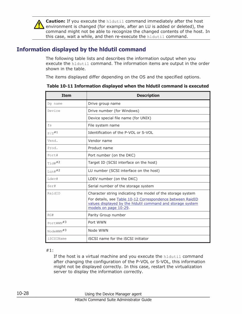
Caution: If you execute the hldutil command immediately after the hostenvironment is changed (for example, after an LU is added or deleted), thecommand might not be able to recognize the changed contents of the host. Inthis case, wait a while, and then re-execute the hldutil command.
Information displayed by the hldutil commandThe following table lists and describes the information output when youexecute the hldutil command. The information items are output in the ordershown in the table.
The items displayed differ depending on the OS and the specified options.
Table 10-11 Information displayed when the hldutil command is executed
Item Description
Dg name Drive group name
Device Drive number (for Windows)
Device special file name (for UNIX)
fs File system name
P/S#1 Identification of the P-VOL or S-VOL
Vend. Vendor name
Prod. Product name
Port# Port number (on the DKC)
Tid##2 Target ID (SCSI interface on the host)
Lun##2 LU number (SCSI interface on the host)
Ldev# LDEV number (on the DKC)
Ser# Serial number of the storage system
RaidID Character string indicating the model of the storage systemFor details, see Table 10-12 Correspondence between RaidIDvalues displayed by the hldutil command and storage systemmodels on page 10-29.
RG# Parity Group number
PortWWN#3 Port WWN
NodeWWN#3 Node WWN
iSCSIName iSCSI name for the iSCSI initiator
#1:If the host is a virtual machine and you execute the hldutil commandafter changing the configuration of the P-VOL or S-VOL, this informationmight not be displayed correctly. In this case, restart the virtualizationserver to display the information correctly.
10-28 Using the Device Manager agentHitachi Command Suite Administrator Guide

#2:In the case of HP-UX 11i v3, this item is not displayed for a persistentspecial device (persistent device special file).
#3:If the virtual WWN is assigned to the virtual machine by using NPIV, thephysical WWN of the virtualization server is displayed.
Table 10-12 Correspondence between RaidID values displayed by thehldutil command and storage system models
RaidID Storage system model
71 Hitachi WMS 100
73 Hitachi AMS 200
75 Hitachi AMS 500
77 Hitachi AMS 1000
81 Hitachi SMS 100
82 Hitachi SMS 110
83 Hitachi AMS2100
85 Hitachi AMS2300
87 Hitachi AMS2500
91 HUS110
92 HUS130
93 HUS150
HM70 HUS VM
R500 Hitachi USP 100, Hitachi USP 600 or Hitachi USP 1100
R501 Hitachi NSC 55
R600 Universal Storage Platform V
R601 Universal Storage Platform VM
R700 Virtual Storage Platform
R800 VSP G1000
Configuration definition file for managing copy pairsIn Device Manager, you can use a user-created CCI configuration definitionfile to manage copy pairs.
Prerequisite environment for using the configuration definition fileTo use the configuration definition file, you need to set up the environment asfollows on the host on which CCI is installed.
Using the Device Manager agent 10-29Hitachi Command Suite Administrator Guide

• Installing a Device Manager agent• Setting the Device Manager server information• Specifying the settings required for using Device Manager to manage copy
pairs
Related topics
• Managing copy pairs on page 10-7• Setting the Device Manager server's information, HiScan command's
execution period, and CCI's information (hdvmagt_setting command) onpage 10-20
• Editing the configuration definition file on page 10-30
Editing the configuration definition fileEdit the horcmXX.conf file, and then refresh the storage system.
To edit the configuration definition file:
1. Open the horcmXX.conf file.The configuration definition file is stored in the directory specified by theserver.agent.rm.horcmSource property of the server.properties filein the Device Manager agent.The default storage location is as follows:
In Windows:System folder (represented by the environment variable %windir%)
In UNIX:/etc directory
If the horcmXX.conf file does not exist, create it.2. Specify the parameters according to the description conventions.3. Use the Device Manager GUI or CLI to refresh the storage system that
contains the copy pair volumes for which the configuration definition filewas created.
Note:
• If a parameter not supported by Device Manager is used, theconfiguration definition file is assumed to be invalid and the system doesnot execute normal processing. Even though a parameter is supported,Device Manager might not support certain description formats. Note thatthe configuration definition file is assumed to be invalid if an item isspecified using an unsupported format.
• Do not specify the following instance numbers and UDP port numbers inthe configuration definition file, because the Device Manager agenttemporarily uses these values to acquire copy pair information:- Instance number: 900 to 998 (default)- UDP port number: 53232 to 53330 (default)
10-30 Using the Device Manager agentHitachi Command Suite Administrator Guide

If these instance numbers or UDP port numbers are used, CCI errorinformation might be output to the system log or event log.
Tip: To change the instance numbers and UDP port numbers that aretemporarily used by the Device Manager agent, use theserver.agent.rm.temporaryInstance andserver.agent.rm.temporaryPort properties in the server.properties file.
Related topics
• Prerequisite environment for using the configuration definition file onpage 10-29
• Notes on using the configuration definition file on page 10-47• agent.rm.horcmInstance on page D-4• agent.rm.horcmService on page D-5• server.agent.rm.temporaryInstance on page D-18• server.agent.rm.temporaryPort on page D-18• server.agent.rm.horcmSource on page D-21
Configuration definition file parameters supported Device ManagerIf you use a parameter not supported by Device Manager, the configurationdefinition file is assumed to be invalid and processing is not performednormally.
Device Manager supports the following parameters:
• HORCM_MON• HORCM_CMD• HORCM_VCMD• HORCM_DEV• HORCM_LDEV• HORCM_INST• HORCM_INSTP• HORCM_CTQM#
#This parameter is supported by Device Manager agent version 6.2 orlater. Note that when you create or use a copy pair, even if HORCM_CTQMinformation is defined in the configuration definition file, the DeviceManager agent will operate while ignoring the definition. The DeviceManager agent does not add the HORCM_CTQM definitions to theconfiguration definition file, nor does it add a pair group to the existingdefinitions. However, when you delete a pair, any definitions of that pairgroup that exist in the HORCM_CTQM definitions will also be deleted.
Using the Device Manager agent 10-31Hitachi Command Suite Administrator Guide

Related topics
• Description conventions for the configuration definition file on page10-32
• HORCM_MON parameter description format on page 10-33• HORCM_CMD parameter description format on page 10-35• HORCM_VCMD parameter description format on page 10-37• HORCM_DEV parameter description format on page 10-37• HORCM_LDEV parameter description format on page 10-40• HORCM_INST parameter description format on page 10-42• HORCM_INSTP parameter description format on page 10-44
Description conventions for the configuration definition fileIf a configuration definition file is not created in accordance with thedescription conventions, Device Manager assumes that the configurationdefinition file is invalid.
Create a configuration definition file in accordance with the followingconventions.
• A configuration definition file cannot include a line that consists only ofspace characters.
• If the version of Device Manager agent is 5.5 or earlier, a line that startswith H and includes any of the following character strings cannot beincluded (except in the starting line of the parameter):HORCM_MON, HORCM_CMD, HORCM_VCMD, HORCM_DEV, HORCM_LDEV,HORCM_INST, HORCM_INSTP, HORCM_CTQM, HORCM_LDEVG,HORCM_ALLOW_INST
• If the version of the Device Manager agent is from 7.0.0 to 7.0.1, avirtual command device must not be defined for the HORCM_CMD parameterin the configuration definition file.
• The configuration definition file must be created in accordance with thefollowing conditions:
¢ HORCM_MON must be defined.¢ At a minimum, either HORCM_DEV or HORCM_LDEV must be defined.¢ At a minimum, either HORCM_INST or HORCM_INSTP must be defined.¢ HORCM_ALLOW_INST must not be defined.
• A virtual ID must not be defined for the HORCM_DEV parameter in theconfiguration definition file.
• If you use CCI 01-32-03/XX or later, the HORCM_DEV parameter or a copypair definition for storage systems that do not support virtual storagemachines must not be defined in the configuration definition file in whichthe HORCM_VCMD parameter is defined.
10-32 Using the Device Manager agentHitachi Command Suite Administrator Guide

• If you use CCI 01-32-03/XX or later, the configuration definition file inwhich the HORCM_VCMD parameter is specified must not include commanddevice definitions for multiple storage systems.
Related topics
• Configuration definition file parameters supported Device Manager onpage 10-31
• HORCM_MON parameter description format on page 10-33• HORCM_CMD parameter description format on page 10-35• HORCM_VCMD parameter description format on page 10-37• HORCM_DEV parameter description format on page 10-37• HORCM_LDEV parameter description format on page 10-40• HORCM_INST parameter description format on page 10-42• HORCM_INSTP parameter description format on page 10-44
HORCM_MON parameter description formatUse the HORCM_MON parameter to specify the machine information for the localhost and the interval for monitoring errors in copy pair volumes.
• ip_addressSpecify the IP address (the Device Manager agent whose version is 5.9 orlater supports the IPv6 protocol), host name, NONE, or NONE6. Note that ifyou use Replication Manager to generate a configuration definition file,this item will always be specified for the host name (Replication Manageruses a Device Manager agent to view the configuration definition file).
¢ Specify the information for the host managed by the Device Managerserver.
¢ Match the IP address version (IPv6 or IPv4) to the one specified forHORCM_INST or HORCM_INSTP.
¢ If an IPv6 environment is being used, specify an IP address. If youspecify a host name, an IPv4 environment is used.
¢ The table below lists the values that can be specified for ip_address.Note that some formats cannot be specified for ip_address becausethey cannot identify a host.
Table 10-13 Values that can be specified for the ip_address ofHORCM_MON parameter
ValueDevice Manager agent version
5.9 or later 05-80 05-70 orearlier
IP address Yes Yes Yes
Host name Yes Yes Yes
Using the Device Manager agent 10-33Hitachi Command Suite Administrator Guide

ValueDevice Manager agent version
5.9 or later 05-80 05-70 orearlier
NONE Yes# Yes# No
"__NONE__" No No No
NONE6 Yes# No No
"__NONE6__" No No No
Loopback IP addresses(127.0.0.1 to127.255.255.254)
Yes# Yes# No
Loopback host name(localhost)
Yes# Yes# No
Cluster virtual IP address No No No
Cluster virtual machine name No No No
Legend:Yes: Can be specified.No: Cannot be specified.#: Can be specified when the copy pair is managed from the DeviceManager CLI. However, this item cannot be specified when copy pairoperations are performed from the Device Manager GUI or ReplicationManager.
• serviceSpecify the port name or port number.
¢ Specify the port name using 1 to 15 single-byte characters. Theenvironment must support the conversion of port names to portnumbers.
¢ Specify the port number as a numeric value from 0 to 65535.• poll
Specify a value (in ten millisecond units) or -1.• timeout
Specify the timeout period in ten millisecond units.
Table 10-14 Support status of HORCM_MON parameter description format
VersionItem
ip_address service poll timeout
6.1 or later Yes Yes Yes Yes
5.9 to 6.0 Yes Only supports portnumberspecification.
Yes Yes
10-34 Using the Device Manager agentHitachi Command Suite Administrator Guide

VersionItem
ip_address service poll timeout
5.8 Supports IP address,host name, andNONE.
Only supports portnumberspecification.
Yes Yes
Earlier than 5.7 Supports IP addressand host name.
Only supports portnumberspecification.
Yes Yes
Legend:Yes: Supports all description formats.
Related topics
• Editing the configuration definition file on page 10-30• Description conventions for the configuration definition file on page 10-32• HORCM_INST parameter description format on page 10-42• HORCM_INSTP parameter description format on page 10-44• Notes on using the configuration definition file on page 10-47
HORCM_CMD parameter description formatSpecify a command device for the storage system in the HORCM_CMDparameter.
• dev_nameSpecify a command device that is recognized by the host. You can specifymore than one command device in the same system, and you can specifya command device in more than one system.In Windows, you can specify a command device in IPCMD format,PhysicalDrive format, GUID format, or CMD format.
IPCMD format\\.\IPCMD-IP-address-of-the-virtual-command-device-port-number[-unit-ID-of-the-storage-system]
PhysicalDrive format\\.\PhysicalDrivedisc-number-defined-by-WindowsFor the Device Manager agent 4.3 or earlier, this item is casesensitive.
GUID format\\.\Volume{GUID}
CMD format\\.\CMD-serial-number[-logical-device-number[-port-name[-host-group-number]]]
Using the Device Manager agent 10-35Hitachi Command Suite Administrator Guide

You must use base-10 numbers to specify the serial number andlogical device number. For the host group number, if the version ofthe Device Manager agent is 5.6 or later, specify a value from 0 to254. If the version of the Device Manager agent is 5.5 or earlier,specify a value from 0 to 127.
In UNIX, you can specify a command device in IPCMD or CMD format, orin a special file.
IPCMD format\\.\IPCMD-IP-address-of-the-virtual-command-device-port-number[-unit-ID-of-the-storage-system]
CMD format\\.\CMD-serial-number[-logical-device-number[-port-name[-host-group-number]]]HINTYou must use base-10 numbers to specify the serial number andlogical device number. For the host group number, if the version ofthe Device Manager agent is 5.6 or later, specify a value from 0 to254. If the version of the Device Manager agent is 5.5 or earlier,specify a value from 0 to 127.Specify the HINT as follows.Solaris: /dev/rdsk/AIX: /dev/rhdiskLinux: /dev/sdHP-UX: /dev/rdsk/ or /dev/rdisk/disk
Table 10-15 Support status of HORCM_CMD parameter description format
VersionItem
dev_name
7.4.1 orlater
Windows Yes
UNIX Yes
7.1 to 7.4.0 Windows Yes
UNIX Only supports specification using a special file or specificationusing IPCMD format.
05-10 to7.0
Windows Supports description formats other than IPCMD format.
UNIX Only supports specification using a special file.
05-00 Windows Supports description formats other than IPCMD and CMDformat.
UNIX Only supports specification using a special file.
Earlier than04-30
Windows Supports description formats other than IPCMD, CMD andGUID formats.
UNIX Only supports specification using a special file.
Legend:
10-36 Using the Device Manager agentHitachi Command Suite Administrator Guide
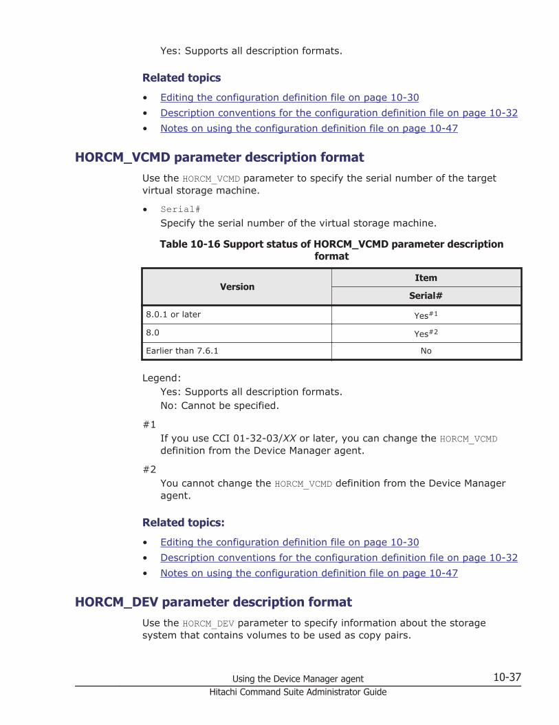
Yes: Supports all description formats.
Related topics
• Editing the configuration definition file on page 10-30• Description conventions for the configuration definition file on page 10-32• Notes on using the configuration definition file on page 10-47
HORCM_VCMD parameter description formatUse the HORCM_VCMD parameter to specify the serial number of the targetvirtual storage machine.
• Serial#Specify the serial number of the virtual storage machine.
Table 10-16 Support status of HORCM_VCMD parameter descriptionformat
VersionItem
Serial#
8.0.1 or later Yes#1
8.0 Yes#2
Earlier than 7.6.1 No
Legend:Yes: Supports all description formats.No: Cannot be specified.
#1If you use CCI 01-32-03/XX or later, you can change the HORCM_VCMDdefinition from the Device Manager agent.
#2You cannot change the HORCM_VCMD definition from the Device Manageragent.
Related topics:
• Editing the configuration definition file on page 10-30• Description conventions for the configuration definition file on page 10-32• Notes on using the configuration definition file on page 10-47
HORCM_DEV parameter description formatUse the HORCM_DEV parameter to specify information about the storagesystem that contains volumes to be used as copy pairs.
Using the Device Manager agent 10-37Hitachi Command Suite Administrator Guide

• dev_groupSpecify the group name.
¢ The combination of the dev_group and dev_name values must not beduplicated in the configuration definition file for a host.
¢ Specify no more than 31 single-byte characters. A hyphen (-) cannotbe specified at the beginning of the character string.
• dev_nameSpecify the name of the pair volume.
¢ The same dev_name value must not be duplicated in a configurationdefinition file.
¢ Specify no more than 31 single-byte characters. A hyphen (-) cannotbe specified at the beginning of the character string.
• port#Specify the port name.If you specify the host group number immediately after specifying theport name for port#, the range of values that you can specify differsdepending on the version of the Device Manager agent. When the versionof the Device Manager agent is 5.6 or later, specify a value from 0 to 254.When the version of the Device Manager agent is 5.5 or earlier, specify avalue from 0 to 127.
• targetIDSpecify the target ID of SCSI/Fibre.
• LU#Specify the LU number of SCSI/Fibre.
• MU#Specify the mirror descriptor using a numeric value or the h addition. Youcan omit this by leaving it blank.The value that can be specified for MU# differs depending on the DeviceManager agent version being used and the copy type.
When the version of the Device Manager agent is 8.0.1 or later:ShadowImage: 0 to 2Copy-on-Write Snapshot: 0 to 63Thin Image: 0 to 63TrueCopy: Not specifiedUniversal Replicator: Not specified#, 0#, h0#, h1, h2, or h3Global-active device: Not specified, h0, h1, h2, or h3#:If no value is specified or if 0 or h0 is specified, multi-targetconfiguration pairs cannot be created with TrueCopy.
When the version of the Device Manager agent is from 7.4.0 to 8.0:ShadowImage: 0 to 2Copy-on-Write Snapshot: 0 to 63
10-38 Using the Device Manager agentHitachi Command Suite Administrator Guide

Thin Image: 0 to 63TrueCopy: Not specifiedUniversal Replicator: Not specified#, 0#, h1, h2, or h3#:If no value is specified or 0 is specified, multi-target configurationpairs cannot be created with TrueCopy.
When the version of the Device Manager agent is from 6.0 to 7.3.1:ShadowImage: 0 to 2Copy-on-Write Snapshot: 0 to 63TrueCopy: Not specifiedUniversal Replicator: Not specified#, 0#, h1, h2, or h3#:If no value is specified or 0 is specified, multi-target configurationpairs cannot be created with TrueCopy.
When the version of the Device Manager agent is from 04-20 to 5.9:ShadowImage: 0 to 2Copy-on-Write Snapshot: 0 to 31TrueCopy: Not specifiedUniversal Replicator: h1, h2, or h3
When the version of the Device Manager agent is 4.0 or 4.1ShadowImage: 0 to 2Copy-on-Write Snapshot: 0 to 13TrueCopy: Not specifiedUniversal Replicator: h1, h2, or h3
When the version of the Device Manager agent is 3.5 or earlierShadowImage: 0 to 2Copy-on-Write Snapshot: 0 to 13TrueCopy: Not specified
Table 10-17 Support status of HORCM_DEV parameter description format
VersionItem
dev_group
dev_name port# targetI
D LU# MU#
04-00 orlater
Yes Yes Yes Yes Yes Yes
Earlier than03-50
Yes Yes Yes Yes Yes Supportsspecification usingmirror descriptors,omissions (blank),and numeric values.
Using the Device Manager agent 10-39Hitachi Command Suite Administrator Guide

Legend:Yes: Supports all description formats.
Related topics
• Editing the configuration definition file on page 10-30• Description conventions for the configuration definition file on page 10-32• Notes on using the configuration definition file on page 10-47
HORCM_LDEV parameter description formatUse the HORCM_LDEV parameter to specify information about the storagesystem that contains copy pairs, and the volume information.
• dev_groupSpecify the group name.
¢ The combination of the dev_group and dev_name values must not beduplicated in the configuration definition file for a host.
¢ Specify no more than 31 single-byte characters. A hyphen (-) cannotbe specified at the beginning of the character string.
• dev_nameSpecify the name of the pair volume.
¢ The same dev_name value must not be duplicated in a configurationdefinition file.
¢ Specify no more than 31 single-byte characters. A hyphen (-) cannotbe specified at the beginning of the character string.
• Serial#Specify the system number of the storage system using the decimalnumber or serial-number:journal-ID format.
• CU:LDEV(LDEV#)Specify the LDEV number using the decimal number, hexadecimalnumber, or CU:LDEV format.The following are examples of LDEV#:
Base-10 numbers260
Hexadecimal numbers0x104
CU:LDEV format01:04
• MU#Specify the mirror descriptor using a numeric value or h addition. You canomit this by leaving it blank.
10-40 Using the Device Manager agentHitachi Command Suite Administrator Guide

The value that can be specified for MU# differs depending on the versionand copy type of the Device Manager agent, as shown below.
When the version of the Device Manager agent is 8.0.1 or later:ShadowImage: 0 to 2Copy-on-Write Snapshot: 0 to 63Thin Image: 0 to 63TrueCopy: Not specifiedUniversal Replicator: Not specified#, 0#, h0#, h1, h2, or h3Global-active device: Not specified, h0, h1, h2, or h3#:If no value is specified or if 0 or h0 is specified, multi-targetconfiguration pairs cannot be created with TrueCopy.
When the version of the Device Manager agent is from 7.4.0 to 8.0:ShadowImage: 0 to 2Copy-on-Write Snapshot: 0 to 63Thin Image: 0 to 63TrueCopy: Not specifiedUniversal Replicator: Not specified#, 0#, h1, h2, or h3#:If no value is specified or 0 is specified, multi-target configurationpairs cannot be created with TrueCopy.
When the version of the Device Manager agent is from 6.0 to 7.3.1:ShadowImage: 0 to 2Copy-on-Write Snapshot: 0 to 63TrueCopy: Not specifiedUniversal Replicator: Not specified#, 0#, h1, h2, or h3#:If no value is specified or 0 is specified, multi-target configurationpairs cannot be created with TrueCopy.
When the version of the Device Manager agent is 5.9 or earlier:ShadowImage: 0 to 2Copy-on-Write Snapshot: 0 to 31TrueCopy: Not specifiedUniversal Replicator: h1, h2, or h3
Table 10-18 Support status of HORCM_LDEV parameter description format
VersionItem
dev_group dev_name Serial# CU:LDEV(LDEV#) MU#
6.2 or later Yes Yes Yes Yes Yes
Using the Device Manager agent 10-41Hitachi Command Suite Administrator Guide

VersionItem
dev_group dev_name Serial# CU:LDEV(LDEV#) MU#
6.1 to05-60
Yes Yes Yes Supports descriptionformats other thanthe serial-number:journal-IDformat.
Yes
Earlier than05-50
No No No No No
Legend:Yes: Supports all description formats.No: Does not support any description formats.
Related topics
• Editing the configuration definition file on page 10-30• Description conventions for the configuration definition file on page 10-32• Notes on using the configuration definition file on page 10-47
HORCM_INST parameter description formatUse the HORCM_INST parameter to specify machine information for the remotehost.
• dev_groupSpecify the contents specified for dev_group of the HORCM_DEV parameteror HORCM_LDEV parameter.
¢ You cannot specify ip_address more than once for the same host fora single dev_group.
¢ Specify no more than 31 single-byte characters. A hyphen (-) cannotbe specified at the beginning of the character string.
• ip_addressSpecify the IP address (a Device Manager agent whose version is 5.9 orlater also supports the IPv6 protocol), the host name, NONE, or NONE6. Ifyou specify NONE or NONE6, the local host is assumed. If you useReplication Manager to add a new group to the existing configurationdefinition file, this item will always be specified using the host name.
¢ Specify the information for the host managed by the Device Managerserver.
¢ Match the IP address version (IPv6 or IPv4) to the one specified forHORCM_MON.
¢ When an IPv6 environment is being used, you cannot specify a hostname. If you specify a host name, an IPv4 environment is used.
10-42 Using the Device Manager agentHitachi Command Suite Administrator Guide

¢ The table below lists the values that can be specified for ip_address.Note that some formats cannot be specified for ip_address becausethey cannot identify a host.
Table 10-19 Values that can be specified for the ip_address ofHORCM_INST parameter
ValueDevice Manager agent version
05-80 or later 05-70 or earlier
IP address Yes Yes
Host name Yes Yes
Loopback IP addresses(127.0.0.1 to127.255.255.254)
Yes# No
Loopback host name(localhost)
Yes# No
Cluster virtual IP address No No
Cluster virtual machine name No No
Legend:Yes: Can be specified.No: Cannot be specified.#: Can be specified when the copy pair is managed from the DeviceManager CLI. However, this item cannot be specified when copy pairoperations are performed from the Device Manager GUI or ReplicationManager.
• serviceSpecify the port name or port number.
¢ Specify the port name using 1 to 15 single-byte characters. Theenvironment must support the conversion of port names to portnumbers.
¢ Specify the port number as a numeric value from 0 to 65535.
Table 10-20 Support status of HORCM_INST parameter description format
VersionItem
dev_group ip_address service
7.0 or later Yes Yes Yes
6.1 to 6.4 Yes Supports IP address andhost name.
Yes
Earlier than6.0
Yes Supports IP address andhost name.
Only supports portnumber specification.
Legend:Yes: Supports all description formats.
Using the Device Manager agent 10-43Hitachi Command Suite Administrator Guide

Related topics
• Editing the configuration definition file on page 10-30• Description conventions for the configuration definition file on page 10-32• HORCM_MON parameter description format on page 10-33• HORCM_DEV parameter description format on page 10-37• HORCM_LDEV parameter description format on page 10-40• Notes on using the configuration definition file on page 10-47
HORCM_INSTP parameter description formatUse the HORCM_INSTP parameter to specify the machine information and pathgroup ID of the remote host.
• dev_groupSpecify the contents specified for dev_group of the HORCM_DEV parameteror HORCM_LDEV parameter.
¢ You cannot specify ip_address more than once for the same host fora single dev_group.
¢ Specify no more than 31 single-byte characters. A hyphen (-) cannotbe specified at the beginning of the character string.
• ip_addressSpecify the IP address, the host name, NONE, or NONE6. If you specifyNONE or NONE6, the local host is assumed. If you use Replication Managerto add a new group to the existing configuration definition file, this itemwill always be specified using the host name.
¢ Specify the information for the host managed by the Device Managerserver.
¢ Match the IP address version (IPv6 or IPv4) to the one specified forHORCM_MON.
¢ When an IPv6 environment is being used, you cannot specify a hostname. If you specify a host name, an IPv4 environment is used.
¢ The table below lists the values that can be specified for ip_address.Note that some formats cannot be specified for ip_address becausethey cannot identify a host.
Table 10-21 Values that can be specified for the ip_address ofHORCM_INSTP parameter
ValueDevice Manager agent version
7.6.0 or later
IP address Yes
Host name Yes
10-44 Using the Device Manager agentHitachi Command Suite Administrator Guide

ValueDevice Manager agent version
7.6.0 or later
Loopback IP addresses (127.0.0.1 to127.255.255.254)
Yes#
Loopback host name (localhost) Yes#
Cluster virtual IP address No
Cluster virtual machine name No
Legend:Yes: Can be specified.No: Cannot be specified.#: Can be specified when the copy pair is managed from the DeviceManager CLI. However, this item cannot be specified when copy pairoperations are performed from the Device Manager GUI or ReplicationManager.
• serviceSpecify the port name or port number.
¢ Specify the port name using 1 to 15 single-byte characters. Theenvironment must support the conversion of port names to portnumbers.
¢ Specify the port number as a numeric value from 0 to 65535.• pathID
Specify the path group ID as a decimal number from 1 to 255.
¢ You cannot specify multiple path group IDs for a single copy group.¢ If you omit path group ID specification (that is, if you select CU Free),
use the HORCM_INST parameter instead of the HORCM_INSTPparameter.
Table 10-22 Support status of HORCM_INSTP parameter descriptionformat
VersionItem
All parameters
7.6.0 or later Yes
6.2 to 7.5.0 Yes#
Earlier than 6.1 No
Legend:Yes: Supports all description formats.Sometimes: The HORCM_INSTP parameter is ignored during copy paircreation or manipulation. During copy pair deletion, if the HORCM_INSTP
Using the Device Manager agent 10-45Hitachi Command Suite Administrator Guide

definition includes a group that has the same name as the copy pairgroup to be deleted, that group is deleted from the definition.No: Does not support any description formats.#: The HORCM_INSTP parameter is ignored during copy pair creation ormanipulation. During copy pair deletion, if the HORCM_INSTP definitionincludes a group that has the same name as the copy pair group to bedeleted, that group is deleted from the definition.
Related topics
• Editing the configuration definition file on page 10-30• Description conventions for the configuration definition file on page 10-32• HORCM_MON parameter description format on page 10-33• HORCM_DEV parameter description format on page 10-37• HORCM_LDEV parameter description format on page 10-40• Notes on using the configuration definition file on page 10-47
Changing the storage location of the configuration definition fileTo change the storage location of the CCI configuration definition file, set thepath of the storage location in the server.agent.rm.horcmSource propertyof the server.properties file of the Device Manager agent.
Operations to complete in advance
Log in as a user with Administrator permissions (for Windows) or as a rootuser (for UNIX).
To change the storage location of the configuration definition file:
1. Execute the hbsasrv command to stop the Device Manager agent service.2. Execute a CCI command to stop all HORCM instances that were manually
started by users.3. Change the storage location of the configuration definition file.4. Specify the new storage location that was changed in step 3 in the
server.agent.rm.horcmSource property of the server.properties fileof the Device Manager agent.
5. Execute the hbsasrv command to start the Device Manager agentservice.
Related topics
• Starting and stopping the Device Manager agent service, and checkingthe operating status of the service (hbsasrv command) on page 10-15
• server.agent.rm.horcmSource on page D-21• To stop an HORCM instance: See the CCI manual.
10-46 Using the Device Manager agentHitachi Command Suite Administrator Guide

Notes on using the configuration definition fileThe following provides notes on using a configuration definition file for CCI tomanage copy pairs.
When editing the configuration definition file:When you use Device Manager to create or change a configurationdefinition file, the information that is defined in the file is automaticallyreported to the Device Manager server.However, if you create or change a configuration definition file withoutusing the Device Manager, for example, by using the Replication Managerinstead or by directly editing the file, you need to manually report the fileinformation to the Device Manager server.If you refresh the storage system via the Device Manager GUI or CLI,information about the configuration definition file is reported to the DeviceManager server. Refresh all storage systems associated with copy pairvolumes that are specified in the configuration definition file.
When optimizing the configuration definition file:If true is specified for theserver.agent.rm.optimization.userHorcmFile property of theserver.properties file, when the Device Manager agent service starts,or when you operate copy pairs, the Device Manager agent optimizes thecontents of the CCI configuration definition file. In this case, note thefollowing:
¢ For backing up the configuration definition file:In the optimization processing, the original configuration definition filehorcmXX.conf is backed up as horcmXX.conf.bk. If the optimizationis performed more than once, the original user-created configurationdefinition file will be lost because only one generation of backup file ismade. Therefore, back up as necessary.
¢ About a comment added to the command device definition:When the CCI configuration definition file is optimized, the unit ID,logical device number, and serial number for the command device areadded as comments on the line before the line on which the commanddevice is defined. In this case, note the following:- Do not change the contents of the comment because the DeviceManager agent references it.- When you copy the CCI configuration definition file that the DeviceManager agent is already managing, and then create a new CCIconfiguration definition file, delete this comment.
When deleting copy pairs:When you delete copy pairs from a management client, if all thedefinitions of the copy pairs in a configuration definition file are deleted,that configuration definition file will also be deleted. If you do not wantthe configuration definition file to be deleted, back up of the configurationdefinition file before you delete the copy pairs.
Using the Device Manager agent 10-47Hitachi Command Suite Administrator Guide

Related topics
• Editing the configuration definition file on page 10-30• server.agent.rm.optimization.userHorcmFile on page D-17
10-48 Using the Device Manager agentHitachi Command Suite Administrator Guide

11Troubleshooting
This chapter describes how to resolve problems that occur during DeviceManager and Tiered Storage Manager operation, and how to collectmaintenance information.
If you need technical support, see Getting help on page xxvi.
□ How to troubleshoot problems on the management server (DeviceManager related)
□ How to troubleshoot problems on the management server (Tiered StorageManager related)
□ How to troubleshoot problems on a host
□ Maintenance information that must be collected if a failure occurs
Troubleshooting 11-1Hitachi Command Suite Administrator Guide
How to troubleshoot problems on the management server(Device Manager related)
This section describes how to troubleshoot problems that occur due to DeviceManager.
The user cannot log in to the Device Manager GUIIf a user cannot log in to the Device Manager GUI, unlock the user account.
Cause
The user account might have been locked.
Countermeasure
For a user without Admin (user management) permission:Ask a user with Admin (user management) permission to unlock theaccount.
For a user with Admin (user management) permission:Ask another user with Admin (user management) permission to unlock theaccount. Alternatively, execute the hcmds64unlockaccount command tounlock your own account.
Related topics:
• Unlocking accounts on page 3-6
The services of Common Component or the Device Manager servercannot be started
If the Common Component or Device Manager server services cannot bestarted, you need to change the desktop heap area.
Cause
The desktop heap might be insufficient.
Countermeasure
Edit the registry to change the area of the desktop heap.
Related topics:
• How to change the area of the desktop heap: Microsoft website
11-2 TroubleshootingHitachi Command Suite Administrator Guide

The Device Manager server cannot be accessed after starting up themanagement server or Hitachi Command Suite product services
If Device Manager cannot be accessed from the GUI or CLI after starting themanagement server or Hitachi Command Suite product services, increase theretry count and the interval for connections to the Device Manager database.
Cause
If the KAIC03100-E error message is output to the Device Manager trace logfile, the communication process from Device Manager server to the databasehas timed out.
Countermeasure
Increase the maximum number of times an attempt to connect to the DeviceManager database can be retried and the interval at which connectionattempts are retried.
In the database.properties file on the Device Manager server, change thevalues of the following properties:
• dbm.startingCheck.retryCount• dbm.startingCheck.retryPeriod
Related topics:
• Changing Device Manager server properties on page A-4• dbm.startingCheck.retryCount on page A-17• dbm.startingCheck.retryPeriod on page A-17
SNMP traps of Hitachi Data Ingestor and Hitachi NAS Platform Fcannot be received
If SNMP traps of Hitachi Data Ingestor and Hitachi NAS Platform F cannot bereceived, make sure that the management server settings, such as the IPaddress and host name, match between Hitachi File Services Manager andDevice Manager.
Cause
The following settings might not match between Hitachi File Services Managerand Device Manager.
• The IP address or host name of the management server• The port number of the management server• The file server name (the IP address or host name of the node)
Troubleshooting 11-3Hitachi Command Suite Administrator Guide

Countermeasure
Check and, if necessary, revise the following settings:
• Whether the IP address or host name of the management server isregistered in the notification destination of SNMP traps.
• Whether the SNMP trap reception port of Device Manager is registered inthe notification destination of SNMP traps.
• Whether the file server name registered in Device Manager matches theIP address or host name of the node registered in Hitachi File ServicesManagerFormat of the file server name: host-name-of-the-node@IP-address-of-the-node
An attempt to reconfigure or refresh a storage system failedIf an attempt to reconfigure or refresh a midrange storage system fails andthe message KAIC05310-E or KAIC06299-E is output, increase the timeoutvalue for communication between the midrange storage system and theDevice Manager server.
Cause
Connection processing from the Device Manager server to the storage systemmight have timed out.
Countermeasure
Extend the timeout interval for communication between the storage systemand the Device Manager server by using the following procedure.
Note that the smaller of the following values is used as the timeout value:
• The value set in the management server OS• The value of the ConnectionTimeout property in the lanconf.inf file
1. In the lanconf.inf, change the value of the ConnectionTimeoutproperty according to the operation environment.The specifiable values range from 1 to 60 seconds.
In Windows:installation-folder-for-Hitachi-Command-Suite\DeviceManager\HiCommandServer\lib\HSNMAPI\lanconf.inf
In Linux:installation-directory-for-Hitachi-Command-Suite/HiCommandServer/lib/HSNMAPI/lanconf.inf
2. Restart Hitachi Command Suite product services.
Related topics:
• Starting the Hitachi Command Suite services on page 8-4
11-4 TroubleshootingHitachi Command Suite Administrator Guide

• Stopping the Hitachi Command Suite services on page 8-5
How to troubleshoot problems on the management server(Tiered Storage Manager related)
This section describes how to troubleshoot problems that occur due to TieredStorage Manager.
Note that operations from the management client here refer to operationsfrom the Tiered Storage Manager CLI only.
The Tiered Storage Manager server could not be startedIf an attempt to start the Tiered Storage Manager server fails, take the actionappropriate for the cause.
Cause
• Device Manager or Common Component has not started.• The user who attempted the operation does not have administrator
permissions.• The property file is invalid.
Countermeasure
If Device Manager or Common Component has not started:Start Device Manager and Common Component.
If the user who attempted the operation does not have administratorpermissions:
Perform the operation again as a user who has administrator permissionsfor the OS.
If the property file is invalid:Revise the property file in accordance with the command logs or themessage logs.
The Tiered Storage Manager server does not stopIf the Tiered Storage Manager server does not stop, take the actionappropriate for the cause.
Cause
• An error occurred in the Tiered Storage Manager server during processingto stop it.
• The user who attempted the operation does not have administratorpermissions.
Troubleshooting 11-5Hitachi Command Suite Administrator Guide

Countermeasure
If a failure occurs on the server while it is being stopped:If 10 minutes have passed since the stop request, and the Tiered StorageManager server is still not stopping, execute the following command:In Windows:installation-folder-for-Hitachi-Command-Suite\TieredStorageManager\bin\htsmserver forcestopIn Linux:installation-directory-for-Hitachi-Command-Suite/TieredStorageManager/bin/htsmserver forcestop
If the user does not have administrator permissions:Perform the operation again through a user who has administratorpermissions for the OS.
The Tiered Storage Manager server terminates abnormally or failsover in a cluster environment
If forced shutdown or another unexpected error causes the Tiered StorageManager server to terminate abnormally or to fail over in an a clusterenvironment, you must restore the consistency between the databaseinformation and the storage system status.
Cause
An inconsistency exists between the database information and the storagesystem status.
Countermeasure
Perform the following procedure to restore the consistency between thedatabase information and the storage system status:
1. After restarting the Hitachi Command Suite product services, refresh allstorage systems by using Device Manager.
2. If the Tiered Storage Manager server terminated abnormally when amigration task was being created or canceled, perform the creation orcancellation again. If an error occurred while a migration was beingcanceled, refresh the storage system.
3. If a migration task that is being executed has failed, refresh the storagesystem again. After that, take action as described below according to thetask status.
If the task status is DATA ERASURE FAILURE:The migration is complete, and the LDEV numbers of the migration sourceand destination have been reversed. Check the status of the sourcevolume that has the destination volume LDEV number, and then take theappropriate action depending on the status. If data was not deleted, theoriginal data remains on the source volume that has the destinationvolume LDEV number.
11-6 TroubleshootingHitachi Command Suite Administrator Guide

¢ If the volume that has the destination LDEV number is blocked, useStorage Navigator to format the volume.
¢ If the volume that has the destination LDEV number is not blocked,the data on the volume might not have been deleted.The data on the volume might not have been deleted. If the datamust be deleted, either format the volume or use the procedure belowto delete the data. Note that the following procedure assumes thatLDEV 10:01 has been migrated to LDEV 20:01 (Also note that theLDEV numbers of the volumes have been reversed.):1. Set a LUN path to LDEV 20:01, and allocate it to a host.2. From the host, enter 0 for the size of the volume to delete any dataremaining on LDEV 20:01.3. Remove the LUN path to LDEV 20:01.
If the task status is MIGRATION FAILURE:Depending on the cause of the error, even if migration processing hasbeen completed in the storage system, Tiered Storage Manager or DeviceManager might treat the processing as having failed. As such, do thefollowing:
a. Use Device Manager to refresh all the storage systems, and updatethe management information in Tiered Storage Manager and DeviceManager.If reserved volumes remain, their reservation is canceled during therefresh processing.
b. For the migration task that is in the failed status, display the volumeinformation and check whether the volumes have already beenmigrated.Also, check the parity group names and storage system names for allLDEVs at the migration source.
c. If there are LDEVs that have not been migrated yet, remove thecause of the error, and then re-create and execute the migration task.
Related topics:
• Starting the Hitachi Command Suite services on page 8-4• Stopping the Hitachi Command Suite services on page 8-5
Tiered Storage Manager operations cannot be performed because anerror occurred in the database
If Tiered Storage Manager has become inoperable due to a database error,restore the database from a previously-created backup.
Cause
The repository cannot be accessed because an error occurred in thedatabase.
Troubleshooting 11-7Hitachi Command Suite Administrator Guide

Countermeasure
Restore a backed up database.
Related topics:
• Restoring databases on page 9-6
How to troubleshoot problems on a hostThis section describes how to troubleshoot problems that occur due to DeviceManager agent.
The HiScan command cannot add host information to the DeviceManager server
If the HiScan command fails to add host information to the Device Managerserver and causes an error message to be output, take the action appropriatefor the cause.
Cause
If the KAIC22019-E error message is output:Possible causes of the error are as follows:
¢ The LUN path to the volume managed by the Device Managerrecognized by the host has been disabled, possibly due to a lostconnection.
¢ This problem might occur if a host recognizes 100 or more LUs thatare managed by Device Manager.
If the KAIC22009-E, KAIC22014-E, or KAIC22048-E error message is output:This problem might occur if a host recognizes 100 or more LUs that aremanaged by Device Manager.
Countermeasure
If the LUN path to a volume that is managed by Device Manager and isrecognized by the host is disabled:
Either restore the disabled LUN path, or change the OS settings so thatthe disabled LUN path is no longer recognized.
If the number of LUs that are managed by Device Manager and arerecognized by the host exceeds 100:
Change the host settings so that the host can manage 100 or more LUsper host.
Related topics:
• Settings required for a host to manage 100 or more LUs on page 10-10
11-8 TroubleshootingHitachi Command Suite Administrator Guide
A communication error occurs, and the processing of other HitachiCommand Suite products stops
If processing of another Hitachi Command Suite product stops due to acommunication error, wait a few minutes and then restart the processing.
Cause
Another Hitachi Command Suite product might have attempted to access theDevice Manager agent either immediately after the installation of the DeviceManager agent was complete, or immediately after the Device Manager agentservices started.
Countermeasure
Wait a few minutes, and then retry the operation.
Two copies of HBase Agent are displayed in the Programs andFeatures window
In a Windows environment, two instances of HBase Agent are sometimesdisplayed in the Programs and Features windows on machines where theDevice Manager agent or Dynamic Link Manager is installed. If two instancesof HBase Agent are displayed, execute the hbsa_util command to deletethe registry entries and files for the Device Manager agent.
Related topics:
• Deleting the Device Manager agent's registry entries and files (hbsa_utilcommand) on page 10-19
HBase Agent is displayed in the Programs and Features windowIn a Windows environment, HBase Agent sometimes remains in thePrograms and Features window after uninstalling both the Device Manageragent and Dynamic Link Manager. If HBase Agent remains, execute thehbsa_util command to delete the registry entries and files for the DeviceManager agent.
Related topics:
• Deleting the Device Manager agent's registry entries and files (hbsa_utilcommand) on page 10-19
JavaVM terminates abnormallyIn a Windows (x64 or IPF) environment, if JavaVM terminates abnormally,edit the Server.cmd file.
Troubleshooting 11-9Hitachi Command Suite Administrator Guide

Cause
Another program linked with Device Manager might be frequently accessingthe Device Manager agent that is running.
Countermeasure
To edit the Server.cmd file:
1. Open the Server.cmd file with a text editor. The location of this file is asfollows:installation-folder-for-Device-Manager-agent\agent\bin\Server.cmd
2. Add -Djava.compiler=NONE as a Java startup option.The following shows an example of editing the Server.cmd file:
.java -Dalet.msglang -Djava.compiler=NONE %1 %2 -classpath"C:\Program Files\HITACHI\HDVM\HBaseAgent\agent\jar\agent4.jar;C:\Program Files\HITACHI\HDVM\HBaseAgent\agent\jar\jdom.jar;C:\Program Files\HITACHI\HDVM\HBaseAgent\agent\jar\xerces.jar;C:\Program Files\HITACHI\HDVM\HBaseAgent\agent\jar\servlet.jar;C:\Program Files\HITACHI\HDVM\HBaseAgent\agent\jar\log4j-1.2.3.jar" com.Hitachi.soft.HiCommand.DVM.agent4.as.export.Server %*exit /b %ERRORLEVEL%
An OutOfMemory error occurs on a host, and after a while the hoststops responding
An OutOfMemory error sometimes occurs on a host when, for example, ahost is refreshed. In this kind of case, if after a while the host stopsresponding, take the action appropriate for the cause.
Cause
• This problem might occur if a host recognizes 100 or more LUs that aremanaged by Device Manager.
• This problem might occur due to high load on the Device Manager server.If so, the following error message will have been output to the log filespecified by the -t option of the HiScan command or to the HiScan.msgfile:
<html><head><title>400 Bad request</title><meta http-equiv="Content-Type" content="text/html; charset=ISO-8859-1"></head><body><h1>400 Bad request</h1><p><strong>ServiceConnection#0: java.lang.OutOfMemoryError</strong></body></html>
The HiScan.msg file is stored in the following locations:
In Windows:installation-folder-for-the-Device-Manager-agent\bin\logs\
11-10 TroubleshootingHitachi Command Suite Administrator Guide

In Linux:installation-directory-for-the-Device-Manager-agent/bin/logs/
In Solaris or HP-UX:/opt/HDVM/HBaseAgent/bin/logs/
In AIX:/usr/HDVM/HBaseAgent/bin/logs/
Countermeasure
• If one host recognizes 100 or more LUs that are managed by DeviceManager, change the host settings so that the host can manage 100 ormore LUs.
• If the Device Manager server is highly loaded, take action as follows:
¢ Change the memory heap size on the Device Manager server.¢ If multiple hosts concurrently execute the HiScan command, use the
hdvmagt_setting command to adjust the HiScan command executionschedule of those hosts.
Related topics:
• Changing the memory heap size on page 1-9• Settings required for a host to manage 100 or more LUs on page 10-10• Setting the Device Manager server's information, HiScan command's
execution period, and CCI's information (hdvmagt_setting command) onpage 10-20
• Reporting host information to the Device Manager server manually(HiScan command) on page 10-22
The file system name is not displayed in the Device Manager GUIIn a Solaris environment, if the file system name is not displayed in theDevice Manager GUI, use VxVM 4.0 or later.
Cause
When using a version of VxVM earlier than 4.0, the Device Manager agentdoes not notify the Device Manager server of correspondence between the filesystem and LUN if device names are set based on the enclosure.
Countermeasure
To check the correspondence between the file system and LUN, use VxVMversion 4.0 or later.
Troubleshooting 11-11Hitachi Command Suite Administrator Guide

Changes to the storage system configuration are not applied to theDevice Manager server
If changes to the storage system configuration are not applied to the DeviceManager server, use the hldutil command or the HiScan command to applythe latest information to the Device Manager server.
Cause
The OS might not recognize the modified contents immediately after thestorage system configuration is changed (for example, when an LU isregistered or deleted). In this case, the Device Manager agent reports the oldinformation to the Device Manager server.
Countermeasure
1. Execute the hldutil command to check the latest information.2. Restart the host OS.3. Execute the HiScan command.
Related topics:
• Reporting host information to the Device Manager server manually(HiScan command) on page 10-22
• Acquiring device information (hldutil command) on page 10-24
Errors requiring no actionFor errors listed below, no action is required.
• The following messages are output to the event log or system log whenmultiple instances of the HiScan command are executed simultaneously:
¢ [HORCM_005] Could not create endpoint for remoteconnection.
¢ [HORCM_007] Illegal parameter values in HORCM configurationfile.
• When a S-VOL in the pair status is being mounted, one of the followingmessages for event ID 51 or 57 is output to the Windows event log:
¢ Event ID: 51An error was detected on device \Device\Harddisknn\DRnduring a paging operation.
¢ Event ID: 57The system failed to flush data to the transaction log.Corruption may occur.
• If the same HiScan command execution interval is set on the active andstandby nodes of the Device Manager agent, SC_DISK_ERR2 (Device Busy)
11-12 TroubleshootingHitachi Command Suite Administrator Guide

or HSDRV_RSV_CONFLICT is output to the AIX error log for the secondarynode.This problem sometimes occurs if the I/O load on the shared disk is high.The active node is providing disk reserve normally for the shared disk,and therefore there is no problem with the system. Shared diskinformation is acquired from the Device Manager agent running on theactive node, and therefore there is no problem with the operation ofDevice Manager.
• The rpm -V command executed in a Linux environment fails.
Maintenance information that must be collected if a failureoccurs
If you cannot identify the cause of a failure or recover from a failure, collectthe maintenance information, and then contact our support center.
If a failure occurs, you need to collect the following information to determinethe cause of the failure:
• System status after the failure• Date and time when the failure occurred• Situation in which the failure occurred• Network configurations of the management server and the host• OSs of the management server and the host• Maintenance information for the computers where the failure occurred
¢ Maintenance information for the management server¢ Maintenance information for Host Data Collector
If you are using Host Data Collector installed on a computer otherthan the management server, you also need to collect maintenanceinformation for the Host Data Collector computer. If Host DataCollector is installed on the management server, executing thehcmds64getlogs command automatically acquires maintenanceinformation for Host Data Collector.
¢ Maintenance information for the host• Java VM thread dump
If any of the following problems occurs, you need to acquire the threaddumps of HBase 64 Storage Mgmt Common Service and HCS DeviceManager Web Service to locate the cause of the problem.
¢ The Device Manager logon window is not displayed when you start theGUI.
¢ The Device Manager main window is not displayed after logging on toDevice Manager.
¢ The Device Manager main window is not displayed when you start aDevice Manager server from Tuning Manager.
Troubleshooting 11-13Hitachi Command Suite Administrator Guide

Note: Depending on the system configuration and where a failure occurs, thelog files of other programs might be required for failure analysis.
• When performance information is viewed from the Mobility tab or theAnalytics tab:The log files of the Tuning Manage server and Tuning Manager - Agent forRAID are required.
• When performance information is viewed from the Replication tab:The log files of the Replication Manager server, Tuning Manager server,and Tuning Manager - Agent for RAID are required.
• When virtualization servers are managed via Device Manager:The log files of the virtualization software and VMware vCenter Server arerequired.
• When Hitachi Data Ingestor or Hitachi NAS Platform F is managed viaDevice Manager:The Hitachi File Services Manager log file is required.
• When application server (host) information is synchronized betweenDevice Manager and Compute Systems Manager:The Compute Systems Manager log file is required.
Related topics
• How to acquire log files for any program other than Device Manager andTiered Storage Manager: the manual for that program.
Acquiring maintenance information on the management server(hcmds64getlogs command)
Execute the hcmds64getlogs command to acquire maintenance informationon the management server.
Operations to complete in advance
Log in as a user with Administrator permissions (for Windows) or as a rootuser (for Linux).
Command format
In Windows:installation-folder-for-Hitachi-Command-Suite\Base64\bin\hcmds64getlogs /dir folder-name [/types Hitachi-Command-Suite-product-name[ Hitachi-Command-Suite-product-name ...]][/arc archive-file-name] [/logtypes log-file-type[ log-file-type ...]]
In Linux:installation-directory-for-Hitachi-Command-Suite/Base64/bin/hcmds64getlogs -dir directory-name [-types Hitachi-Command-Suite-product-name[ Hitachi-Command-Suite-product-name ...]]
11-14 TroubleshootingHitachi Command Suite Administrator Guide

[-arc archive-file-name] [-logtypes log-file-type[ log-file-type ...]]
Caution: Do not execute more than one hcmds64getlogs commandsimultaneously.
Note: If Hitachi File Services Manager or Storage Navigator Modular 2 islinked, you can also collect maintenance information for Hitachi File ServicesManager or Storage Navigator Modular 2 by omitting the types and logtypesoptions when you execute the command.
Options
dirSpecify the absolute path to the directory on a local disk that containscollected maintenance information. If the directory has already beencreated, empty the directory.The maximum length of a path name that can be specified is 41 bytes.You can specify any printable ASCII character excluding certain specialcharacters. You cannot specify the following characters:\ / : , ; * ? " < > | $ % & ' `However, you can specify backslashes (\), colons (:), and forwardslashes (/) in Windows, or forward slashes (/) in Linux as a pathdelimiter. Do not specify a path delimiter at the end of a path name.In Windows, to specify a space character in a path name, enclose thepath name in double quotation marks ("). In Linux, you cannot specify aspace character in a path name.
typesSpecify the names of the products to be acquired by using the table belowif the maintenance information for only specific Hitachi Command Suiteproducts can be collected. To specify multiple product names, separatethem by a space.
Table 11-1 Values specified for the type option when collectingmaintenance information
Product Value
Device Manager DeviceManager
Tiered Storage Manager TieredStorageManager
Replication Manager ReplicationManager
Other products Refer to the manual for each product.
When specifying this option, also specify the log file type log for thelogtypes option.If this option is not specified, the maintenance information for all HitachiCommand Suite products installed on the same management server iscollected.
Troubleshooting 11-15Hitachi Command Suite Administrator Guide

arcSpecify the name of the archive files to be created. If you do not specifythis option, the default file name is HiCommand_log_64.For the file name, you can specify any printable ASCII character excludingcertain special characters. You cannot specify the following characters:\ / : , ; * ? " < > | $ % & ' `In Linux, you cannot specify a space character in a file name.
logtypesSpecify the types of log files to acquire when log files of a particular typecannot be collected due to a failure.log: Specify this to acquire .jar files and .hdb.jar files only.db: Specify this to acquire .db.jar files only.csv: Specify this to acquire .csv.jar files only.To specify multiple types, separate them by a space.If you omit this option, all log files will be acquired.
Note: If the Replication tab is used in a large-scale system environment,obtaining maintenance information takes time, and the maintenanceinformation files are large. Therefore, to execute the hcmds64getlogscommand, we recommend that you specify the following option to obtain themaintenance information.
In Windows:installation-folder-for-Hitachi-Command-Suite\Base64\bin\hcmds64getlogs /dir folder-name /logtypes log csv
In Linux:installation-directory-for-Hitachi-Command-Suite/Base64/bin/hcmds64getlogs -dir directory-name -logtypes log csv
When this command is executed, the KAPM05318-I or KAPM05319-Emessage is output. In addition, maintenance information (log file anddatabase file) is acquired and four archive files (.jar, .hdb.jar, .db.jar,and .csv.jar) are output in the directory specified in the dir option.
Tip: If the KAPM05318-I or KAPM05319-E message is not output, thehcmds64getlogs command did not complete because sufficient free spacewas not available for the directory specified in the dir option. Free upsufficient space in the directory, and then re-execute the hcmds64getlogscommand.
Generating the Tiered Storage Manager CLI log fileIf the Tiered Storage Manager CLI is installed on the management server,you can use the hcmds64getlogs command to collect Tiered Storage ManagerCLI log files with the other log files. To acquire both log files by using oneoperation, you must specify the environment settings in the HtsmgetTI.properties file.
11-16 TroubleshootingHitachi Command Suite Administrator Guide

To collect Tiered Storage Manager CLI log files:
1. Set the necessary properties in the HtsmgetTI.properties file stored inthe following location.
In Windows:installation-folder-for-Hitachi-Command-Suite\TieredStorageManager\SupportTools\CollectTool\
In Linux:installation-directory-for-Hitachi-Command-Suite/TieredStorageManager/SupportTools/CollectTool/
Table 11-2 Properties set in the HtsmgetTI.properties file
Property Description
CLI_DIR Specify the directory in which Tiered Storage Manager CLI is installed.The following are the default installation directories:In Windows:
installation-folder-for-Hitachi-Command-Suite\TieredStorageManager\CLI
In Linux:installation-directory-for-Hitachi-Command-Suite/TieredStorageManager/CLI
SYSLOG In Linux, specify the absolute path to syslog. The default directory is:/var/log/messages
Acquiring maintenance information for a Host Data Collectorcomputer (hdc_getras command)
Execute the hdc_getras command to acquire maintenance information for aHost Data Collector computer that manages virtualization servers.
Operations to complete in advance
Log in as a user with Administrator permissions (for Windows) or as a rootuser (for Linux).
Command format
In Windows:installation-folder-for-Host-Data-Collector\HDC\Base\bin\hdc_getras.bat -o folder-name [-f]
In Linux:installation-directory-for-Host-Data-Collector/HDC/Base/bin/hdc_getras.sh -o directory-name [-f]
• o
Troubleshooting 11-17Hitachi Command Suite Administrator Guide

Use the absolute path or a relative path from the current directory tospecify the output destination for the maintenance information.You can specify any printable ASCII character other than the followingspecial characters:\ / : , ; * ? " < > | $ % & ' ` ^However, you can specify backslashes (\), colons (:), and forwardslashes (/) in Windows, or forward slashes (/) in Linux as a pathdelimiter.
• fUse this option to forcibly overwrite the directory if the directory specifiedby the o option already exists.
Maintenance information is output to the following location:
In Windows:folder-specified-for-the-o-option\hdcResult
In Linux:directory-specified-for-the-o-option/hdcResult
Acquiring maintenance information on a host managed by Host DataCollector (hdc_target_getras command)
Execute the hdc_target_getras command to acquire maintenanceinformation on a normal host or virtual machine managed by Host DataCollector.
Operations to complete in advance
• Copy a file to the hostCopy the following file to the target managed host from the computer onwhich Host Data Collector is installed:
In Windows:installation-folder-for-Host-Data-Collector\Base\bin\hdc_target_getras.bat
In UNIX:installation-directory-for-Host-Data-Collector/Base/bin/hdc_target_getras.sh
• Log in as a user with Administrator permissions (for Windows) or as aroot user (for UNIX)
Command format
In Windows:hdc_target_getras.bat -o folder-name [-f]
In UNIX:hdc_target_getras.sh -o directory-name [-f]
11-18 TroubleshootingHitachi Command Suite Administrator Guide

• oUse the absolute path or a relative path from the current directory tospecify the output destination for the maintenance information.You can specify any printable ASCII character other than the followingspecial characters:\ / : , ; * ? " < > | $ % & ' ` ^However, you can specify backslashes (\), colons (:), and forwardslashes (/) in Windows, or forward slashes (/) in UNIX as a pathdelimiter.
• fUse this option to forcibly overwrite the directory if the directory specifiedby the o option already exists.
Maintenance information is output to the following location:
In Windows:folder-specified-for-the-o-option\target_hdcResult
In UNIX:directory-specified-for-the-o-option/target_hdcResult
Acquiring maintenance information on the Device Manager agent(TIC command)
Execute the TIC command to acquire maintenance information on a normalhost or virtual machine managed by the Device Manager agent.
Operations to complete in advance
Log in as a user with Administrator permissions (for Windows) or as a rootuser (for UNIX).
Command format
In Windows:TIC.bat [-outdir folder-name [-f] [-d [addon-module-name]]]
In Solaris or HP-UX:TIC.sh [-outdir directory-name [-f] [-d [addon-module-name]]]
In AIX or Linux:TIC.sh [-outdir directory-name [-f]]
Location of the command
In Windows:installation-folder-for-Device-Manager-agent\bin
In Linux:installation-directory-for-Device-Manager-agent/bin
Troubleshooting 11-19Hitachi Command Suite Administrator Guide

In Solaris or HP-UX:/opt/HDVM/HBaseAgent/bin
In AIX:/usr/HDVM/HBaseAgent/bin
Options
-outdirUse the absolute path or a relative path from the current directory tospecify the output destination for the maintenance information.Note that you cannot use the following characters for any elements otherthan path separators:\ / : , ; * ? " < > | $ % & ' ` ^If this option is omitted, the directory that contains the TIC command willbe used as the output destination.
-fSpecify this option to forcibly overwrite the directory specified by the -outdir option if the specified directory already exists.
-dSpecify the following abbreviations for add-on modules whose errorinformation you wish to remove from the acquisition target:hglm: Global Link Manager agent (Windows, Solaris, or HP-UX only)hrpmap: Replication Manager Application agentIf you specify multiple parameters, separate them with commas (,). Ifthe name of the add-on module is omitted, the error information for theGlobal Link Manager agent and Replication Manager Application agent isnot acquired.
Maintenance information is output to the following location:
In Windows:folder-specified-for-the-outdir-option\resultDir
In UNIX:directory-specified-for-the-outdir-option/resultDir
Acquiring a thread dump of the HBase 64 Storage Mgmt CommonService (Windows)
To acquire a thread dump of HBase 64 Storage Mgmt Common Service,create a file called dump, and then restart HBase 64 Storage Mgmt CommonService.
11-20 TroubleshootingHitachi Command Suite Administrator Guide

To acquire a thread dump of HBase 64 Storage Mgmt CommonService:
1. In installation-folder-for-Hitachi-Command-Suite\Base64\uCPSB\CC\web\containers\HiCommand64, create a file called dump.
2. Access the Windows Services window.3. Stop the HBase 64 Storage Mgmt Common Service.4. From the Services window, start the HBase 64 Storage Mgmt Common
Service.
The javacorexxx.xxxx.txt file is output when using JDK bundled withHitachi Command Suite, or the HiCommand64.log file is output when usingOracle JDK, to the following folder:
installation-folder-for-Hitachi-Command-Suite\Base64\uCPSB\CC\web\containers\HiCommand64If you are using the Oracle JDK, the HiCommand64.log file is overwritten eachtime it is output. We recommend saving the file by using a different nameafter the file is output.
Acquiring a thread dump of the HCS Device Manager Web Service(Windows)
To acquire a thread dump of HCS Device Manager Web Service, create a filecalled dump, and then restart HCS Device Manager Web Service.
To acquire a thread dump of HCS Device Manager Web Service:
1. In installation-folder-for-Hitachi-Command-Suite\Base64\uCPSB\CC\web\containers\DeviceManagerWebService, create a file calleddump.
2. Access the Windows Services window.3. Stop the HCS Device Manager Web Service.4. From the Services window, start the HCS Device Manager Web Service.
The javacorexxx.xxx.txt file is output when using JDK bundled with HitachiCommand Suite, or the DeviceManagerWebService.log file is output whenusing Oracle JDK, to the following folder:
installation-folder-for-Hitachi-Command-Suite\Base64\uCPSB\CC\web\containers\DeviceManagerWebServiceIf you are using the Oracle JDK, the DeviceManagerWebService.log file isoverwritten each time it is output. We recommend saving the file by using adifferent name after the file is output.
Troubleshooting 11-21Hitachi Command Suite Administrator Guide

Acquiring a thread dump of the HBase 64 Storage Mgmt CommonService (Linux)
To acquire a thread dump of HBase 64 Storage Mgmt Common Service,execute the kill command, and then restart the Hitachi Command Suiteproduct services.
To acquire a thread dump of HBase 64 Storage Mgmt CommonService:
1. Execute the following command:# kill -3 PIDPID is a process ID written in the installation-directory-for-Hitachi-Command-Suite/Base64/uCPSB/CC/web/containers/HiCommand64/logs/cjstdout.log file.Multiple process IDs are written to the cjstdout.log file. Specify the lastprocess ID written to the file.
2. Restart the Hitachi Command Suite product services.
The javacorexxx.xxx.txt file is output when using JDK bundled with HitachiCommand Suite, or the HiCommand64.log file is output when using OracleJDK, to the following directory:
installation-directory-for-Hitachi-Command-Suite/Base64/uCPSB/CC/web/containers/HiCommand64If you are using the Oracle JDK, the HiCommand64.log file is overwritten eachtime it is output. We recommend saving the file by using a different nameafter the file is output.
Related topics
• Starting the Hitachi Command Suite services on page 8-4• Stopping the Hitachi Command Suite services on page 8-5
Acquiring a thread dump of the HCS Device Manager Web Service(Linux)
To acquire a thread dump of HCS Device Manager Web Service, execute thekill command, and then restart the Hitachi Command Suite productservices.
To acquire a thread dump of HCS Device Manager Web Service:
1. Execute the following command:# kill -3 PIDPID is a process ID written in theinstallation-directory-for-Hitachi-Command-Suite/Base64/uCPSB/CC/web/containers/DeviceManagerWebService/logs/cjstdout.log file.Multiple process IDs are written to the cjstdout.log file. Specify the lastprocess ID written to the file.
11-22 TroubleshootingHitachi Command Suite Administrator Guide

2. Restart the Hitachi Command Suite product services.
The javacorexxx.xxx.txt file is output when using JDK bundled with HitachiCommand Suite, or the DeviceManagerWebService.log file is output whenusing Oracle JDK, to the following directory:
installation-directory-for-Hitachi-Command-Suite/Base64/uCPSB/CC/web/containers/DeviceManagerWebServiceIf you are using the Oracle JDK, the DeviceManagerWebService.log file isoverwritten each time it is output. We recommend saving the file by using adifferent name after the file is output.
Related topics
• Starting the Hitachi Command Suite services on page 8-4• Stopping the Hitachi Command Suite services on page 8-5
Troubleshooting 11-23Hitachi Command Suite Administrator Guide

11-24 TroubleshootingHitachi Command Suite Administrator Guide

ADevice Manager server properties
This section describes the property files of a Device Manager server.
□ Device Manager server property files
□ Device Manager server configuration properties (server.properties file)
□ Device Manager database properties (database.properties file)
□ Device Manager log output properties (logger.properties file)
□ Device Manager dispatcher properties (dispatcher.properties file)
□ Device Manager MIME type properties (mime.properties file)
□ Device Manager client properties (client.properties file)
□ Device Manager security properties (server.properties file andcimxmlscpa.properties file)
□ Device Manager SNMP trap log output properties(customizedsnmptrap.properties file)
□ Device Manager launchable applications properties (launchapp.propertiesfile)
□ Properties for communicating with the host (host.properties file)
□ Properties for connecting to Host Data Collector(hostdatacollectors.properties file)
□ Properties for migrations (migration.properties file)
Device Manager server properties A-1Hitachi Command Suite Administrator Guide

□ Properties for connecting to Tuning Manager (tuningmanager.propertiesfile)
□ Properties related to Universal Replicator performance analysis(replication.properties file)
□ Properties for connecting to Replication Manager (rpmlib.properties file)
□ Properties for the CIM/WBEM functions (jserver.properties file,cimxmlcpa.properties file, cimxmlscpa.properties file)
A-2 Device Manager server propertiesHitachi Command Suite Administrator Guide

Device Manager server property filesDevice Manager server property files include property files related to DeviceManager configuration information and the Device Manager database.
The following table describes the contents of property files of a DeviceManager server.
Table A-1 Property files of a Device Manager server
Property file Description
server.properties file This property file contains the Device Manager serverconfiguration information.Warning:
Do not attempt to optimize these attributes unless youare an expert, because even minor changes couldseverely impact the performance of the Device Managerserver.
database.properties file This property file is related to the Device Manager database.Warning:
Do not attempt to optimize these attributes unless youare an expert, because even minor changes couldseverely impact the performance of the Device Managerserver.
logger.properties file This property file is related to the Device Manager logoutput.
dispatcher.propertiesfile
This property file is related to Device Manager threads.
mime.properties file This property file is related to MIME (Multipurpose InternetMail Extensions) types for Device Manager.
client.properties file This property file is related to the Device Manager GUI.
• server.propertiesfile
• cimxmlscpa.properties file
This property file is related to Device Manager security.
customizedsnmptrap.properties file
This property file is related to the log output of the SNMPtraps received by Device Manager.
launchapp.propertiesfile
This property file is related to the applications that can belaunched from Device Manager.
host.properties file This property file is related to communicating with hosts.
hostdatacollectors.properties file
This property file is related to the connection to Host DataCollector.
migration.propertiesfile
This property file is related to migrations.
tuningmanager.properties file
This property file is related to the connection to TuningManager.
Device Manager server properties A-3Hitachi Command Suite Administrator Guide

Property file Description
replication.propertiesfile
This property file is related to Universal Replicatorperformance analysis.
rpmlib.properties file This property file is related to the connection to ReplicationManager.
• jserver.propertiesfile
• cimxmlcpa.properties file
• cimxmlscpa.properties file
This property file is related to the CIM/WBEM functions.
Caution:
• For ordinary use, you do not need to change the values set in theproperty files of a Device Manager server.Use extreme caution when you are modifying the values, because you cancause the server to fail or to function incorrectly. Do not modify thevalues unless you have sufficient expertise.
• The default values are set during a new installation.• If you perform an overwrite or upgrade installation, values set in the
property files of a Device Manager server before the installation areinherited.
Changing Device Manager server propertiesUse a text editor to edit the property files of a Device Manager server.
Operations to complete in advance
Log in as a user with Administrator permissions (for Windows) or as a rootuser (for Linux).
To change the Device Manager server properties:
1. Stop the services of Hitachi Command Suite product.2. Use a text editor to specify the appropriate values in the Device Manager
server property files.3. Start the services of Hitachi Command Suite product.
Related topics
• Starting the Hitachi Command Suite services on page 8-4• Stopping the Hitachi Command Suite services on page 8-5
Syntax rules for Device Manager server property filesThe property files are in the Java property file format.
A-4 Device Manager server propertiesHitachi Command Suite Administrator Guide

Property files must be created according to the following descriptionconventions:
• Each property must be entered as a combination of a property name andvalue separated by an equals sign (=). For example, foo.bar=12345.
• Each property must be separated by a line delimiter (a line feedcharacter).
• A line beginning with a hash mark (#) is a comment line.• You do not need to insert quotation marks around literals (text strings or
numerical values).• The backslash (\) is reserved as an escape character. Since absolute path
names in Windows include backslashes, you must add an escapecharacter before every backslash in a Windows path name.For example, the path name of the file C:\HiCommand\docroot\foo.barshould be entered as C:\\HiCommand\\docroot\\foo.bar. When youspecify properties, there is no need to precede other characters with theescape character \.
• If two or more entries in a property file have the same property name,the value of the last such property specified in the file will take effect.
• If a line ends with a backslash (\), the next line is a continuation of thecurrent line.
Device Manager server configuration properties(server.properties file)
The server.properties file contains the server configuration properties.
• In Windows:installation-folder-for-Hitachi-Command-Suite\DeviceManager\HiCommandServer\config\server.properties
• In Linux:installation-directory-for-Hitachi-Command-Suite/HiCommandServer/config/server.properties
server.http.hostSpecify host names or IP addresses of the management server (DeviceManager server).
To specify the IP address, use one of the following formats:
IPv4 format:x.x.x.x (x: integer from 0 to 255)
IPv6 format:Specify hexadecimal numbers by using colons (:). You can also use ashort format. You can only use global IPv6 addresses.
Device Manager server properties A-5Hitachi Command Suite Administrator Guide

A value specified for the host name or IP address must be accessible fromclients (GUI, CLI, and storage systems).
Default: The host name or IP address of the management server specifiedduring installation (if an error occurs when registering the URL, localhost isset).
Caution:
• If multiple NICs are installed on the server computer on which DeviceManager is installed, specify the IP address of the NIC that belongs to thenetwork to which the clients (GUI, CLI, and storage systems) connect. Donot specify the host name.
• In a cluster environment, the IP address of the cluster manager should bespecified.
• If Device Manager manages SMI-S enabled storage systems and thesetting value of this property has been changed, you must refresh anySMI-S enabled storage system that is a management target.
• If user accounts are authenticated in Hitachi Command Suite whenlogging in to CCI or the SVP and the value of this property has beenchanged, reconfigure user account authentication in the Edit StorageSystems window in the Device Manager GUI.
server.http.portSpecify the port to be used for non-SSL communication by the DeviceManager server.
The conventional port number used for a standard web server is 80, but theremight already be an intranet server running on this port. Moreover, youshould avoid low-numbered ports because these could conflict with otherservices installed on the server. As a general rule, you can pick any portbetween 1024 and 49151.
80 is used for the port number when this property is set to a space character.
Default: 2001
Caution: If you change the value of this property, you also need to changethe following settings:
• The port number for Device Manager registered in the Device Manageragent (the hdvmagt_setting command)
• The hdvm.port property of the Tiered Storage Manager server• The port number for the Device Manager server of the information source
registered in Replication Manager (for non-SSL communication with theDevice Manager server)
• The port number for the Device Manager server registered in the fileserver management software
A-6 Device Manager server propertiesHitachi Command Suite Administrator Guide

• The HiCommandCLI.serverurl property of the HiCommandCLI.propertiesfile in the Device Manager CLI (for non-SSL communication with theDevice Manager server)
Related topics
• Changing pop-up blocker settings on page 4-67• Enabling SSL/TLS for the Device Manager CLI computer on page 4-68• Changing the communication protocol between the Replication Manager
server and the Device Manager server on page 4-75• Setting the Device Manager server's information, HiScan command's
execution period, and CCI's information (hdvmagt_setting command) onpage 10-20
• Changing Tiered Storage Manager server properties on page B-2• hdvm.port on page B-9• Changing the port number in the file server management software: See
the file server manuals.
server.https.portSpecify the port to be used for SSL communication by the Device Managerserver.
The conventional port number for a secure web server is 443, but there mightalready be a secure intranet server running on this port. As noted above, it isbetter practice to utilize a port number between 1024 and 49151 for aspecialized (middleware) HTTP server. Make sure that it has a different valuethan the port designated for the HTTP listener.
Default: 2443
Caution: If you change the value of this property, you also need to changethe following settings:
• The port number for Device Manager registered in the Device Manageragent (the hdvmagt_setting command)
• The port number for the Device Manager server of the information sourceregistered in Replication Manager (for SSL communication with the DeviceManager server)
• The HiCommandCLI.serverurl property of the HiCommandCLI.propertiesfile in the Device Manager CLI (for SSL communication with the DeviceManager server)
In addition, if user accounts are authenticated in Hitachi Command Suitewhen logging in to CCI or the SVP and the value of this property has beenchanged, reconfigure user account authentication in the Edit Storage Systemswindow in the Device Manager GUI.
Device Manager server properties A-7Hitachi Command Suite Administrator Guide

Related topics
• Changing pop-up blocker settings on page 4-67• Enabling SSL/TLS for the Device Manager CLI computer on page 4-68• Changing the communication protocol between the Replication Manager
server and the Device Manager server on page 4-75
server.rmi.portSpecify the port used for the Device Manager RMI server.
You should avoid low-numbered ports because these could conflict with otherservices installed on the server. As a general rule, you can pick any portbetween 1024 and 65535.
Default: 23055
Caution: If you change the value of this property, you must also change thevalues of the Device Manager server client.rmi.port property and theTiered Storage Manager hdvm.rmi.port property to the same value.
Related topics
• client.rmi.port on page A-29• hdvm.rmi.port on page B-9
server.http.entity.maxLengthSpecify in bytes the maximum length of an HTTP request entity to bepermitted by the Device Manager server.
Under normal conditions, you do not need to change the default value of thisproperty. It helps prevent certain types of denial of service and attemptedbuffer overflow attacks by restricting the effect of malicious requests thatcontain unusually large payload entities. If the server detects a postedrequest longer than this value, it sends an error response to the client andlogs details of the attempted request.
Default: 1310720
Note: If you register a file server that has many file systems and storagepools into Device Manager, information sent from the file server might not beapplied to Device Manager properly. In this case, change the property valueto a value greater than the default.
server.base.homeThis property contains the installation directory of Common Component,which is set by the Device Manager installer.
Under normal conditions, you do not need to change the default value of thisproperty.
A-8 Device Manager server propertiesHitachi Command Suite Administrator Guide

Default: Value set by the installer
server.horcmconfigfile.hostnameSpecify whether to use the IP address (ipaddress) or the host name(hostname) when Device Manager edits the configuration definition file.
Default: ipaddress
Caution:
• Changing the IP address or host name specified when a copy pair wascreated might disable operations on the copy pair. If this is the case, youneed to modify the configuration definition file and refresh the storagesystems.
• The setting for this property is ignored in Replication Manager. If you editthe configuration definition file in Replication Manager, the host name isalways used.
Related topics
• Notes on managing copy pairs on page 1-60
server.base.initialsynchroSpecify whether to synchronize the management information database andthe displayed information (Common Component repository) when you startDevice Manager.
A setting of true will synchronize the information. A setting of false will notsynchronize the information.
Default: false
Caution: If this property is set to true, synchronization of the informationwill take several minutes. If you change the property and then log in toDevice Manager right away, an error might occur. In such a case, wait untilthe synchronization has finished, and then log in.
server.cim.agentSpecify the name of the host on which the Device Manager agent is installedwhen the function for acquiring storage system performance information isused.
Performance information can be acquired only when this property is specified.
Default: None
server.cim.supportSpecify whether CIM support is enabled.
Device Manager server properties A-9Hitachi Command Suite Administrator Guide

If you want to execute CIM, you must set this property to true.
Default: true
server.cim.support.jobSpecify whether a method for creating or deleting a volume, setting orreleasing a LUN path, setting or canceling security for a LUN, or creating ordeleting a LUSE volume is executed asynchronously or synchronously.
If you set this property to true, the method is executed asynchronously. Ifyou set this property to false, the method is executed synchronously. If theCIM client does not support the job control subprofile, specify false.
If you specify any values other than true or false, or if this property doesnot exist, the method is executed asynchronously.
Default: true
server.cim.support.protocolSpecify whether to open or close the ports used by the CIM function.
A value of 1 to 3 can be specified. The value specified for this propertydetermines whether to open or close the non-SSL communication ports(default: 5988/tcp) and SSL communication ports (default: 5989/tcp).
1: The non-SSL communication ports are open, and the SSL communicationports are closed.
2: The non-SSL communication ports are closed and the SSL communicationports are open.
3: Both the non-SSL communication ports and the SSL communication portsare open.
Default: 3
Related topics
• server.cim.http.port on page A-10• server.cim.https.port on page A-11
server.cim.http.portSpecify the port for non- SSL transmission for the CIM function.
Default: 5988
Caution: If you change the value of this property, also change the HTTPPortproperty of the Device Manager server to the same value.
A-10 Device Manager server propertiesHitachi Command Suite Administrator Guide

Related topics
• server.cim.support.protocol on page A-10• HTTPPort on page A-52
server.cim.https.portSpecify the port for SSL transmission, for the CIM function.
Default: 5989
Caution: If you change the value of this property, also change theHTTPSPort property of the Device Manager server to the same value.
Related topics
• server.cim.support.protocol on page A-10• HTTPSPort on page A-52
server.configchange.enabledSpecify whether to automatically update (refresh) storage system informationin the database when the storage system configuration is changed by astorage management tool (Element Manager) launched from the GUI.
For Universal Storage Platform V/VM, or Hitachi USP, if you specify true,storage system information in the database is automatically refreshedimmediately after the configuration change. For HUS100, Hitachi AMS2000,Hitachi SMS, or Hitachi AMS/WMS, if you specify true, whether theconfiguration has been changed is checked at the interval specified in thefollowing properties, and storage system information in the database isautomatically refreshed if the configuration has been changed:
For HUS100, Hitachi AMS2000 or Hitachi SMSserver.dispatcher.snm2.configchange.pollingPeriod property
For Hitachi AMS/WMSserver.dispatcher.configchange.pollingPeriod property
If you specify false, storage system information in the database is notautomatically refreshed.
Default: true
Related topics
• server.dispatcher.snm2.configchange.pollingPeriod on page A-21• server.dispatcher.configchange.pollingPeriod on page A-22
Device Manager server properties A-11Hitachi Command Suite Administrator Guide

server.logicalview.initialsynchroSpecify whether to forcibly synchronize the storage system information in thedatabase with the information displayed in the GUI or CIM/WBEM functionswhen Device Manager server is started.
If you specify true, the information will be synchronized. If you specifyfalse, the information will not be synchronized.
Default: false
server.mail.enabled.storagesystemSpecify whether to send storage system alerts, events, and health checkresults to users by email.
To enable this email notification function, set this property to true. To disablethis function, set this property to false.
Default: true
Caution: If this property is set to true, set the server.mail.smtp.hostproperty.
Related topics
• server.mail.smtp.host on page A-13
server.mail.enabled.fileserverSpecify whether to send Hitachi NAS Platform alerts to users by email.
To enable this email notification function, set this property to true. To disablethis function, set this property to false.
For Hitachi NAS Platform, the timing of when polls and SNMP traps detecterrors is different, but the same information is displayed in their alerts.Therefore, if you specify true, alerts for both the polls and SNMP traps aresent by email.
Default: true
Caution: If this property is set to true, set the server.mail.smtp.hostproperty.
Related topics
• server.mail.smtp.host on page A-13
A-12 Device Manager server propertiesHitachi Command Suite Administrator Guide

server.mail.fromSpecify the email address of the notification source (sender) used to sendalerts, events, and health check results to users by email.
Depending on the operating environment, users might not receive email froman address that does not include a domain name. In this case, change thevalue of this property or the email settings (including the SMTP server andreceiver filter settings).
If no value is specified or the specified value is invalid, the default value isset.
Default: hdvmserver
server.mail.smtp.hostSpecify the host name or IP address of the SMTP server.
To send alerts, events, and health check results to users by email, you mustspecify this property. The IP address can be specified in either IPv4 or IPv6format.
Default: None
Caution: If you set this property, specify true for theserver.mail.enabled.storagesystem orserver.mail.enabled.fileserver property.
Related topics
• server.mail.enabled.storagesystem on page A-12
server.mail.smtp.portSpecify the port number of the SMTP server.
To send alerts, events, and health check results to users by email, you mustspecify this property.
Specifiable range: 0 to 65535.
Default: 25
server.mail.smtp.authSpecify whether to use SMTP authentication to send alerts, events, andhealth check results to users by email.
To use SMTP authentication, set this property to true. To not use SMTPauthentication, set this property to false.
Default: false
Device Manager server properties A-13Hitachi Command Suite Administrator Guide

server.mail.errorsToSpecify the address to which an undeliverable notification email will be sentwhen alert email notifications, event email notifications, and health checkresults email notifications cannot be delivered.
If this property is not specified, notifications for undeliverable emails are sentto the email address specified in server.mail.from in theserver.properties file of the Device Manager server. Note that theconditions for sending undeliverable notification emails vary according to theSMTP server settings. Make sure to review these settings.
Default: None
Related topics
• server.mail.from on page A-13
server.eventNotification.mail.toSpecify the send destination address for alert and event notification emails.
All alerts and events are sent to the email address specified in this property.
Default: None
server.mail.alert.type.storagesystemSpecify the type of storage system alerts that are sent to users by email.
The following values can be specified:
• Trap: Reports only the alerts detected by SNMP traps.• Server: Reports only the alerts detected by the polls that Device Manager
conducts.• All: Reports the alerts detected by both SNMP traps and the polls that
Device Manager conducts. Alerts are reported from both SNMP traps andthe polls conducted by Device Manager even if these alerts refer to thesame error information.
Default: Trap
server.mail.alert.statusSpecify the severity of alerts that are sent to users by email.
The Device Manager server reports alerts whose severity is equal to or higherthan the severity specified for this property. The following values (listed inascending order of severity) can be specified:
Normal, Service, Moderate, Serious, AcuteDefault: Moderate
A-14 Device Manager server propertiesHitachi Command Suite Administrator Guide

server.subsystem.ssid.availableValuesSpecify the range of the SSIDs that can be assigned automatically to storagesystems registered in Device Manager.
This property is valid for VSP G1000, Virtual Storage Platform, UniversalStorage Platform V/VM, Hitachi USP and HUS VM.
The values that can be specified for this property are as follows:
• Hexadecimal numbers in the range from 4 to FFFD: To specifyconsecutive numbers, use a hyphen (-) to specify the range. To specifynon-consecutive numbers, use commas as separators. The values are notcase sensitive. If multiple values and ranges that include duplicatednumbers are specified, the logical union of all specified values is used.
• All: The string All specifies that the entire range of values can bespecified. This value is not case sensitive.
Automatic SSID assignment can be performed only when a value or valuesare specified in this property.
Default: All
server.smisclient.indication.portSpecify the port number used to receive event indications from SMI-Sproviders.
Specifiable range: 1024 to 49151.
If the setting value of this property has been changed, you must refresh anySMI-S enabled storage system that is managed by Device Manager.
Default: 5983
server.agent.differentialrefresh.manual.enabledSpecify whether to update the database information only for resources whoseconfiguration has changed since the last refresh when manually refreshing astorage system.
This property is valid only for VSP G1000, Virtual Storage Platform or HUS VMstorage systems.
If you specify true for this property, refresh processing is more efficientbecause database updates are skipped for resources whose configuration hasnot changed since the last refresh.
Specify false to update all storage system resource information in thedatabase regardless of whether the configuration has changed.
Default: true
Device Manager server properties A-15Hitachi Command Suite Administrator Guide

server.agent.differentialrefresh.periodical.enabledSpecify whether to update the database information only for resources whoseconfiguration has changed since the last refresh when automaticallyrefreshing a storage system.
This property is valid only for VSP G1000, Virtual Storage Platform or HUS VMstorage systems.
If you specify true for this property, refresh processing is more efficientbecause database updates are skipped for resources whose configuration hasnot changed since the last refresh.
Specify false to update all storage system resource information in thedatabase regardless of whether the configuration has changed.
Default: true
server.logicalGroupMapping.updateIntervalWhen using Health Check, to omit the processing to obtain configurationinformation about the volumes of logical groups, specify the interval duringwhich the processing is to be omitted (in minutes).
By default, Health Check reports for logical groups are always created basedon the most recent volume configuration information. If Device Manager ismanaging many volumes, the processing to obtain configuration informationabout the volumes of logical groups might take a long time. In anenvironment in which the configuration of the volumes in a logical group doesnot change frequently, the processing to obtain configuration information canbe omitted, and Health Check can be performed based on the last volumeconfiguration information obtained. By doing so, you can shorten the timerequired to create reports.
Because this property is not present by default, specify it as follows:
server.logicalGroupMapping.updateInterval=time-in-minutesAfter a Health Check is performed, for any Health Check performed from thattime until the specified interval has elapsed, reports will be created based onthe last volume configuration information obtained.
Device Manager database properties (database.propertiesfile)
The database.properties file contains the database properties.
• In Windows:installation-folder-for-Hitachi-Command-Suite\DeviceManager\HiCommandServer\config\database.properties
• In Linux:
A-16 Device Manager server propertiesHitachi Command Suite Administrator Guide

installation-directory-for-Hitachi-Command-Suite/HiCommandServer/config/database.properties
This property file contains the directives that pertain to establishing aconnection with the Device Manager server's database. Before the DeviceManager server can run you need to correctly enter these settings and startthe Database Management System (DBMS). If the server cannot connect toits DBMS, an entry is written to the error log (the default location is in thelogs directory). This information can help considerably when you aretroubleshooting a new installation.
dbm.traceSQLSpecify whether to output SQL to trace log.
Set true to output SQL. Set false not to output SQL.
Default: false
dbm.startingCheck.retryCountSpecify the number of times that the Device Manager server (at startup)retries checking of whether the DBMS has started.
The specifiable values are from 0 to 100. Under normal conditions, you do notneed to change the default value of this property.
Default: 18
dbm.startingCheck.retryPeriodSpecify the interval (in seconds) that the Device Manager server (at startup)retries checking of whether the DBMS has started.
The specifiable values are from 0 to 60 (seconds). Under normal conditions,you do not need to change the default value of this property.
Default: 10 (seconds)
Device Manager log output properties (logger.propertiesfile)
The logger.properties file contains the log output properties.
• In Windows:installation-folder-for-Hitachi-Command-Suite\DeviceManager\HiCommandServer\config\logger.properties
• In Linux:installation-directory-for-Hitachi-Command-Suite/HiCommandServer/config/logger.properties
Device Manager server properties A-17Hitachi Command Suite Administrator Guide

This property file contains a set of directives that configure the DeviceManager server's logging module, including the names, locations andverbosity level of the various operation and error log files. You can also usethis file to configure trace logging for debugging and diagnostic purposes.
logger.loglevelSpecify the verbosity level for the trace.log, error.log, CIMOMTrace.log,and SMISClientTrace.log.
The values accepted in this field are (in decreasing order of detail): DEBUG,INFO, WARN, ERROR, and FATAL. If this property is set to the default, entrieswhose verbosity level is either INFO, WARN, ERROR, or FATAL are written intothe trace.log. In this case, entries whose verbosity level is DEBUG are notwritten into the logs.
Default: INFO
logger.MaxBackupIndexSpecify the maximum number of backups for the access.log,cim_access.log, error.log, service.log, stdout.log, stderr.log,statuscheck.log, trace.log, CIMOMTrace.log, and SMISClientTrace.log.
When a log file reaches its maximum size (as specified in thelogger.MaxFileSize property), the file is renamed and a counter is addedinto the file name (for example, access.log.1). As more backup log files arecreated, their counters or version suffixes are incremented (for example,access.log.1 becomes access.log.2), until the specified number ofbackups have been created. After that, the oldest backup log file is deletedeach time a new backup is created.
Specifiable values are from 1 to 20.
Default: 10
Related topics
• logger.MaxFileSize on page A-18
logger.MaxFileSizeSpecify the maximum size for the access.log, cim_access.log, error.log,service.log, stdout.log, stderr.log, statuscheck.log, trace.log,CIMOMTrace.log, and SMISClientTrace.log.
If the maximum size is exceeded, a new log file is created. Unless KB isspecified for kilobytes or MB for megabytes, the specified size is interpreted tomean bytes.
Specifiable range: from 512 KB to 32 MB
Default: 1 MB
A-18 Device Manager server propertiesHitachi Command Suite Administrator Guide

logger.hicommandbase.loglevelSpecify the verbosity level for each operation (trace) log file and error log filewritten by Common Component. The log files are HDvMtracen.log,HDvMGuiTracen.log, and HDvMGuiMessagen.log, where n is an integer thatrepresents the backup number for the file.
Each logging event has its own importance level independent from its type(error, warning, and information). The levels, in increasing order ofimportance, are: 30, 20, 10, and 0. The default logging level for productionsystems is 20, which means that messages for logging event levels 20, 10,and 0 are written to HDvMtrace1.log, but messages for logging event level30 are not.
Default: 20
logger.hicommandbase.sysloglevelSpecify the verbosity level for the operation (trace) log data and error logdata written to the event log (in Windows) or to syslog (in Linux) by CommonComponent.
Each logged event has its own importance level independent from its type(error, warning, and information). The levels, in increasing order ofimportance, are: 30, 20, 10 and 0. The default logging level for productionsystems is 0, which means that only messages for the logging event level 0are written to the event log (in Windows) or to syslog (in Linux), butmessages for the logging event level 30, 20, and 10 are not. The defaultvalue is recommended.
Default: 0
logger.hicommandbase.MaxBackupIndexSpecify the maximum number of backups for each trace and error log file thatis written by Common Component. The log files are HDvMtracen.log,HDvMGuiTracen.log, and HDvMGuiMessagen.log (the n in the file nameindicates the backup generation number of the file).
When a log file reaches the size specified in thelogger.hicommandbase.MaxFileSize property, a new log file is created witha counter added to the file name, for example HDvMtrace2.log. If thenumber of log files reaches the value specified in this property, log files areoverwritten starting from the oldest file.
Valid values are from 1 to 16.
Default: 10
Related topics
• logger.hicommandbase.MaxFileSize on page A-20
Device Manager server properties A-19Hitachi Command Suite Administrator Guide

logger.hicommandbase.MaxFileSizeSpecify the maximum size of each operation (trace) log file and error log filethat is written by Common Component. The log files are HDvMtracen.log,HDvMGuiTracen.log, and HDvMGuiMessagen.log (the n in the file nameindicates the backup generation number of the file).
The specified size is assumed to be in bytes unless you specify KB forkilobytes, MB for megabytes or GB for gigabytes.
Valid values are from 4096 to 2147483647 (less than 2 GB).
Default: 5 MB
Device Manager dispatcher properties(dispatcher.properties file)
The dispatcher.properties file contains the dispatcher properties.
• In Windows:installation-folder-for-Hitachi-Command-Suite\DeviceManager\HiCommandServer\config\dispatcher.properties
• In Linux:installation-directory-for-Hitachi-Command-Suite/HiCommandServer/config/dispatcher.properties
This property file contains a set of configurable directives pertaining to theoperation of the Device Manager server's dispatcher layer, includingproperties that allow the fine-tuning of various background processes(daemons) and the optimization of the thread-priority for service agents.
server.dispatcher.message.timeoutSpecify the timeout (in minutes) for pending response messages before theyare expired (purged).
A pending message contains a response from a process that has beenrunning for a long time (such as the addition of a storage system) but has notyet been polled by the client or has not yet been sent to the client via theDevice Manager notification service.
Default: 15 (minutes)
server.dispatcher.message.timeout.in.processingSpecify the timeout period (in minutes) for the GUI processing and CLIprocessing that does not complete for some reason.
Default: 720 (minutes)
A-20 Device Manager server propertiesHitachi Command Suite Administrator Guide

server.dispatcher.daemon.pollingPeriodSpecify the polling interval (in minutes) for the background threadsresponsible for checking component status and the configuration version.
A value of 0 will disable these pollings.
Default: 5 (minutes)
Caution: When polling is executed in HUS100, Hitachi AMS2000, or in HitachiSMS, the I/O performance of the storage system might be affected. If youwant to reduce the affect, set a larger polling interval or disable polling.
server.dispatcher.traps.purgePeriodSpecify the purging interval for stale SNMP traps or alerts (in minutes).
A value of 0 will disable the purging of traps from the server.
Default: 5 (minutes)
server.dispatcher.daemon.receiveTrapSpecify whether Device Manager receives SNMP traps generated by networkresources such as storage systems and switches.
To receive SNMP traps, set this property to true. To not receive SNMP traps,set this property to false.
The port 162/udp is used for receiving SNMP traps. When a new installationof Hitachi Command Suite is performed, if this port is not used by anotherproduct, this property is automatically set to true.
Default: true
server.dispatcher.snm2.configchange.pollingPeriodSpecify the interval (in seconds) at which the Device Manager server checkswhether the configuration of HUS100, Hitachi AMS2000 or Hitachi SMS ischanged by Storage Navigator Modular 2 launched from the GUI.
If the server.configchange.enabled property is set to true and the DeviceManager server detects changes in the storage system configuration, storagesystem information in the database is automatically updated (refreshed).
You can specify a value from 0 to 3600. If you specify 0, storage systeminformation in the database is not refreshed when the storage systemconfiguration is changed because the Device Manager server does not detectthe change.
Default: 300 (seconds)
Device Manager server properties A-21Hitachi Command Suite Administrator Guide

Related topics
• server.configchange.enabled on page A-11
server.dispatcher.configchange.pollingPeriodSpecify the interval (in seconds) at which the Device Manager server checkswhether the configuration of Hitachi AMS/WMS is changed by ElementManager.
If the server.configchange.enabled property is set to true and the DeviceManager server detects changes in the storage system configuration, storagesystem information in the database is automatically updated (refreshed).
You can specify a value from 0 to 3600. If you specify 0, storage systeminformation in the database is not updated when the storage systemconfiguration is changed because the Device Manager server does not detectthe change.
Default: 60 (seconds)
Related topics
• server.configchange.enabled on page A-11
server.dispatcher.daemon.configUpdate.detection.intervalSpecify the interval (in minutes) at which the Device Manager server checkswhether the configuration of VSP G1000, Virtual Storage Platform, UniversalStorage Platform V/VM, or HUS VM is changed by a storage management toolother than Device Manager (such as CCI or SVP).
If the Device Manager server detects changes in the configuration of VSPG1000, Virtual Storage Platform, Universal Storage Platform V/VM, or HUSVM, the Device Manager GUI displays a warning message.
You can specify a value from 0 to 1440. If you specify 0, the Device Managerserver does not check whether the configuration of VSP G1000, VirtualStorage Platform, Universal Storage Platform V/VM, or HUS VM is changed.
Default: 10 (minutes)
Caution:
• If the GUI displays a warning message, manually refresh thecorresponding storage system information.You can also specify the settings so that information in the database isautomatically updated in case a user forgets to perform a manual refreshafter changing the storage system configuration. To do so, set up thefollowing properties:server.dispatcher.daemon.autoSynchro.doRefresh propertyserver.dispatcher.daemon.autoSynchro.type property
A-22 Device Manager server propertiesHitachi Command Suite Administrator Guide

• The Device Manager server cannot detect the following configurationchanges:- Changes in the LDEV status (such as normal, blocked, or being copied).- Creating, changing, or deleting copy pairsIn addition, the Device Manager server cannot detect changes to theaccess attribute of LDEVs (such as Read/Write, Read Only, or Protect)that are performed on Universal Storage Platform V/VM.
• In the Device Manager server the configurations of storage system aretreated as changed for the following triggers:- Restarting SVP- Refreshing the configuration information of storage system displayed inStorage Navigator.- Switching the SVP in a cluster configuration from the executing node tothe standby node, or vice versa.- Turning on the DKC- The configuration of a DP pool is changed#
The configuration of the Copy-on-Write Snapshot data pool or the ThinImage data pool is changed#
#:For VSP G1000, Virtual Storage Platform or HUS VM, if you specify falsefor theserver.dispatcher.daemon.configUpdate.detection.variable.enabled property, you can prevent a warning message from being displayed inthe Device Manager GUI when the pool configuration is changed.
Related topics
• server.dispatcher.daemon.autoSynchro.doRefresh on page A-23• server.dispatcher.daemon.autoSynchro.type on page A-24• server.dispatcher.daemon.configUpdate.detection.variable.enabled on
page A-25
server.dispatcher.daemon.autoSynchro.doRefreshSpecify whether to automatically refresh the storage system information inthe database if the Device Manager server detects that the configuration of aVSP G1000, Virtual Storage Platform, Universal Storage Platform V/VM, orHUS VM storage system has changed.
If true is specified for this property and a user does not perform a manualrefresh after the Device Manager server detects a change, the information ofVSP G1000, Virtual Storage Platform, Universal Storage Platform V/VM, orHUS VM in the database is automatically refreshed at the interval specified inthe server.dispatcher.daemon.autoSynchro.type property. If false isspecified, the database is not automatically refreshed.
Default: true
Device Manager server properties A-23Hitachi Command Suite Administrator Guide

Caution: If you specify true, only the information about the VSP G1000,Virtual Storage Platform, Universal Storage Platform V/VM, or HUS VM isupdated in the database. The information in the configuration file of a hostthat recognizes the command device of VSP G1000, Virtual Storage Platform,Universal Storage Platform V/VM, or HUS VM is not updated in the database.
Related topics
• server.dispatcher.daemon.autoSynchro.type on page A-24
server.dispatcher.daemon.autoSynchro.typeSpecify the interval at which storage system information in the database isautomatically updated (refreshed) using one of the following values:
H: Specify this format to automatically refresh the information at regularintervals. Specify the interval in theserver.dispatcher.daemon.autoSynchro.interval property.
D: Specify this format to automatically refresh the information once a day ata specific time. Specify the time in theserver.dispatcher.daemon.autoSynchro.startTime property.
W: Specify this format to automatically refresh the information once a week ata specific time on a specific day. Specify the day in theserver.dispatcher.daemon.autoSynchro.dayOfWeek property, and the timein the server.dispatcher.daemon.autoSynchro.startTime property.
This property is enabled only if theserver.dispatcher.daemon.autoSynchro.doRefresh property is set totrue.
Default: D
Related topics
• server.dispatcher.daemon.autoSynchro.doRefresh on page A-23• server.dispatcher.daemon.autoSynchro.dayOfWeek on page A-24• server.dispatcher.daemon.autoSynchro.startTime on page A-25• server.dispatcher.daemon.autoSynchro.interval on page A-25
server.dispatcher.daemon.autoSynchro.dayOfWeekSpecify the day on which storage system information in the database isautomatically updated (refreshed) using one of the following values:
Sun Mon Tue Wed Thu Fri SatThis property is enabled only if theserver.dispatcher.daemon.autoSynchro.type property is set to W. Inaddition, storage system information is automatically refreshed (updated)according to the time zone setting for the management server.
A-24 Device Manager server propertiesHitachi Command Suite Administrator Guide

Default: Fri
Related topics
• server.dispatcher.daemon.autoSynchro.type on page A-24
server.dispatcher.daemon.autoSynchro.startTimeSpecify the time at which storage system information is automaticallyrefreshed (updated) in the database starts in the format hh:mm.
Specify a value from 00 to 23 for hh, and 00 to 59 for mm. This property isenabled only if the server.dispatcher.daemon.autoSynchro.type propertyis set to D or W. In addition, storage system information is automaticallyrefreshed (updated) according to the time zone setting for the managementserver.
Default: 23:00
Related topics
• server.dispatcher.daemon.autoSynchro.type on page A-24
server.dispatcher.daemon.autoSynchro.intervalSpecify the interval (in hours) at which storage system information in thedatabase is automatically updated (refreshed).
You can specify a value from 1 to 24.
This property is enabled only if theserver.dispatcher.daemon.autoSynchro.type property is set to H.
Default: 24 (hours)
Related topics
• server.dispatcher.daemon.autoSynchro.type on page A-24
server.dispatcher.daemon.configUpdate.detection.variable.enabledSpecify whether to monitor items with values that change sequentially, suchas the usage rate of DP pools and the usage rate of Copy-on-Write Snapshotdata pools, when the Device Manager server checks if the configuration ofVSP G1000, Virtual Storage Platform or HUS VM has been changed.
If true is specified, then the items are monitored. The Device Manager GUIdisplays a warning message when the Device Manager server detectschanges in the values. If false is specified, the following changes are notmonitored, and the Device Manager GUI does not display a warning message.
• A change in the usage rate of the following volumes:
Device Manager server properties A-25Hitachi Command Suite Administrator Guide

¢ HDP volume¢ HDP pool¢ HDT pool¢ Data pool of Copy-on-Write Snapshot¢ Data pool of Thin Image
• A change in the threshold value for the usage rate of the followingvolumes:
¢ HDP pool¢ HDT pool¢ Data pool of Copy-on-Write Snapshot¢ Data pool of Thin Image
• A change in the maximum reservation amount of the following volumes:
¢ HDP pool¢ HDT pool¢ Data pool of Copy-on-Write Snapshot¢ Data pool of Thin Image
• A change in the monitoring mode for the HDT pool• A change in the settings regarding performance monitoring and
hierarchical relocation of the HDT pool• A change in the settings regarding tiering policy for the HDT volume.
The HDT volume is a virtual volume created from the HDT pool(associated with the HDT pool).
This property is enabled only if values other than 0 are specified for theserver.dispatcher.daemon.configUpdate.detection.interval property.
Default: false
Related topics
• server.dispatcher.daemon.configUpdate.detection.interval on page A-22
server.dispatcher.daemon.autoSynchro.performance.doRefreshSpecify whether to automatically update (refresh) the performanceinformation displayed in the Mobility tab.
If true is specified for this property, the storage system performanceinformation is automatically refreshed at the time specified in theserver.dispatcher.daemon.autoSynchro.performance.startTime propertyover the interval specified in the htnm.infoAcquirePeriod property.
If false is specified for this property, the storage system performanceinformation is not automatically refreshed. To refresh the performanceinformation, use either of the following methods:
A-26 Device Manager server propertiesHitachi Command Suite Administrator Guide

• When using the GUI:In the Refresh Storage Systems window, select the RefreshPerformance data check box, and then refresh the storage system.
• When using the CLI:Execute the RefreshPerformanceData command.
Default:true
Related topics
• server.dispatcher.daemon.autoSynchro.performance.startTime on pageA-27
• htnm.infoAcquirePeriod on page A-43
server.dispatcher.daemon.autoSynchro.performance.startTimeSpecify the time at which performance information displayed in the Mobilitytab is automatically updated in the format hh:mm.
Specify a value from 00 to 23 for hh, and 00 to 59 for mm. This property isenabled only if theserver.dispatcher.daemon.autoSynchro.performance.doRefresh propertyis set to true.
Default:00:10
Related topics
• server.dispatcher.daemon.autoSynchro.performance.doRefresh on pageA-26
server.dispatcher.daemon.autoSynchro.logicalGroup.doRefreshSpecify whether to automatically update logical group information when anyof the operations below occur.
If this property is set to true, logical group information is automaticallyupdated each time one of the events below occurs.
• Registering a storage system• Refreshing a storage system• Deleting a storage system• Automatically updating performance information (over the interval
specified in htnm.infoAcquirePeriod)• Creating and editing a logical group• Creating, editing, and deleting a user group• Editing and deleting a resource group
Device Manager server properties A-27Hitachi Command Suite Administrator Guide

Note that logical group information is automatically updated only when theabove operations are performed from the GUI.
If the above operations are executed from the CLI when this property is setto true or if this property is set to false, logical group information is notautomatically updated. To update the information, select a logical group fromLogical Groups under the Mobility tab, and then click the Refresh Databutton.
Default:true
Related topics
• htnm.infoAcquirePeriod on page A-43
server.dispatcher.daemon.logicalGroupMappingUpdate.startTimeIn the hh:mm format, specify the time to start executing the task thatcollects logical groups in the background. The logical groups to be collectedare those that have volumes belong to them and appear in the Analyze MPBlade/Unit window of the Analytics tab.
Specify a value in the range from 00 to 23 for hh and a value in the rangefrom 00 to 59 for mm.
The default value is 02:00.
Device Manager MIME type properties (mime.propertiesfile)
The mime.properties file contains the MIME type properties.
• In Windows:installation-folder-for-Hitachi-Command-Suite\DeviceManager\HiCommandServer\config\mime.properties
• In Linux:installation-directory-for-Hitachi-Command-Suite/HiCommandServer/config/mime.properties
This property file contains the translation and lookup table for all MIME typesrecognized by the Device Manager server. Each property in this lookup tablemaps a particular extension suffix to the MIME type for that file. Undernormal conditions, you do not need to change the default values in this file.In any event, only expert system administrators should make any additionsto this file.
Device Manager client properties (client.properties file)The client.properties file contains the client properties.
• In Windows:
A-28 Device Manager server propertiesHitachi Command Suite Administrator Guide

installation-folder-for-Hitachi-Command-Suite\DeviceManager\HiCommandServer\config\client.properties
• In Linux:installation-directory-for-Hitachi-Command-Suite/HiCommandServer/config/client.properties
This property file contains the settings related to display and operation ofDevice Manager GUI.
client.rmi.portSpecify the port number for the Device Manager RMI server.
You must specify the same value as the one specified for theserver.rmi.port property of the Device Manager server.
Default: 23055
Related topics
• server.rmi.port on page A-8
Device Manager security properties (server.properties fileand cimxmlscpa.properties file)
The server.properties and cimxmlscpa.properties file contains thesecurity properties.
• server.properties file
¢ In Windows:installation-folder-for-Hitachi-Command-Suite\DeviceManager\HiCommandServer\config\server.properties
¢ In Linux:installation-directory-for-Hitachi-Command-Suite/HiCommandServer/config/server.properties
• cimxmlscpa.properties file
¢ In Windows:installation-folder-for-Hitachi-Command-Suite\DeviceManager\HiCommandServer\wsi\server\jserver\bin\cimxmlscpa.properties
¢ In Linux:installation-directory-for-Hitachi-Command-Suite/HiCommandServer/wsi/server/jserver/bin/cimxmlscpa.properties
Device Manager server properties A-29Hitachi Command Suite Administrator Guide

server.http.security.clientIPSpecify IP addresses, in IPv4 format, that can be used to connect to theDevice Manager server.
The server.http.security.clientIP property is in the server.propertiesfile.
This setting limits the IP addresses permitted for connection, thus preventingdenial-of-service attacks or other attacks that intend to overflow buffers.
The following shows a specification example when the Device Manager serveraccepts connections from 172.16.0.1 and IP addresses in the range from192.168.0.0 to 192.168.255.255:
server.http.security.clientIP=172.16.0.1,192.168.*.*You can use asterisks as a wildcard character when specifying multipleconnection sources by using a single IP address. To specify multiple IPaddresses, separate them with commas. Invalid IP addresses and spaces areignored.
Default: *.*.*.* (Any IP address can be used to connect to the DeviceManager server.)
Caution:
• You do not need to specify the IP address (the local loopback address) ofthe computer on which the Device Manager server is installed. In thisproperty, it is assumed that the Device Manager server can always beconnected to using the local loopback address.
• You also need to register the IP addresses to the environment definitionfile user_httpsd.conf for Common Component.
Related topics
• Registering IP addresses in the environment definition fileuser_httpsd.conf of Common Component: Controlling managementclient access to the management server on page 4-122
server.http.security.clientIPv6Specify IP addresses, in IPv6 format, that can be used to connect to theDevice Manager server.
The server.http.security.clientIPv6 property is in theserver.properties file.
This setting limits the IP addresses permitted for connection, thus preventingdenial-of-service attacks or other attacks that intend to overflow buffers.
The following shows a specification example when the Device Manager serveraccepts connections from IP addresses in the range from 12AB:0:0:CD30:: to12AB:0:0:CD3F:FFFF:FFFF:FFFF:FFFF.
A-30 Device Manager server propertiesHitachi Command Suite Administrator Guide

server.http.security.clientIPv6=12AB:0:0:CD30::/60You can specify a range of IP addresses in CIDR format. To specify multipleIP addresses, separate them with commas. Invalid IP addresses and spacesare ignored.
Default: :: (Any IP address can be used to connect to the Device Managerserver.)
Caution:
• You do not need to specify the IP address (the local loopback address) ofthe computer on which the Device Manager server is installed. In thisproperty, it is assumed that the Device Manager server can always beconnected to using the local loopback address.
• You also need to register the IP addresses to the environment definitionfile user_httpsd.conf for Common Component.
Related topics
• Registering IP addresses in the environment definition fileuser_httpsd.conf of Common Component: Controlling managementclient access to the management server on page 4-122
server.https.security.keystoreSpecify the name of the keystore file that contains the keypair and associatedserver certificate used for establishing encrypted communications via SSL orTLS.
The server.https.security.keystore property is in theserver.properties file.
The keystore file shipped with a Device Manager server is an emptyplaceholder file that does not contain the required keypair and associatedserver certificate needed to run the Device Manager server in secure mode. Ifyou attempt to start the server in secure mode with an empty keystore file,the server will log a fatal error and terminate abnormally. A keypair andassociated self-signed or trusted certificate must first be installed into thekeystore before encrypted communications can be started.
Default: keystore
server.http.security.unprotectedSpecify a comma-delimited list of any non-protected file resources under theserver's document root.
The server.http.security.unprotected property is in theserver.properties file.
To specify multiple file resources, separate them with commas. Spaces areignored. When files or directories are designated as unprotected, they are
Device Manager server properties A-31Hitachi Command Suite Administrator Guide

not subject to Access Control List checks (user authentication), regardless ofthe security mode setting for the server. Entire directories (including nestedsub-directories) can be flagged as unprotected by using an asterisk as awildcard character. If you specify a space, all resources are protected, so thatevery request to the Device Manager server will require user authentication.
This property allows anyone to view the index.html front page via abrowser, without user authentication being required. More importantly, itallows the Java Web Start application to update its JAR file and deploy (viathe HiCommand.jnlp file) to the end-user's system without the appearance ofa series of logon dialog boxes. Similarly, the GUI's help files (and certainclient installation information) can be viewed via a web browser withoutseparate authentication being required at each step. Under normalconditions, you do not need to change the default value of this property.
Default: index.html, HiCommand/*, webstart/*, images/*, style/*,docs/*, favicon.ico
server.https.security.truststoreSpecify the truststore file of the Device Manager server.
The server.https.security.truststore property is in theserver.properties file.
Default: dvmcacerts
Note: This property cannot be modified with HiKeytool. If you want to changethe value, you must do so by editing the value in the server.propertiesfile.
server.https.enabledCipherSuitesSpecify the cipher suites to be used for the following SSL/TLS communicationby using commas (,) to separate them.
• Between the Device Manager server and a Web browser• Between the Device Manager server and the Device Manager CLI• Between the Device Manager server and a Device Manager agent• Between the Device Manager server and Replication Manager server
The server.https.enabledCipherSuites property is in theserver.properties file.
The specifiable cipher suites are as follows:
• TLS_RSA_WITH_AES_256_CBC_SHA256• TLS_RSA_WITH_AES_256_CBC_SHA• TLS_RSA_WITH_AES_128_CBC_SHA256• TLS_RSA_WITH_AES_128_CBC_SHA• SSL_RSA_WITH_3DES_EDE_CBC_SHA
A-32 Device Manager server propertiesHitachi Command Suite Administrator Guide

Default: TLS_RSA_WITH_AES_256_CBC_SHA256,TLS_RSA_WITH_AES_256_CBC_SHA, TLS_RSA_WITH_AES_128_CBC_SHA256,TLS_RSA_WITH_AES_128_CBC_SHA, SSL_RSA_WITH_3DES_EDE_CBC_SHA
CiphersSpecify the cipher suites to be used for SSL/TLS communication between theDevice Manager server and a CIM client (object operations and indicationnotifications) by using commas (,) to separate them.
The cipher suites used by default are as follows:
• TLS_RSA_WITH_AES_128_CBC_SHA256• TLS_RSA_WITH_AES_128_CBC_SHA• SSL_RSA_WITH_3DES_EDE_CBC_SHAThe cimxmlscpa.properties file and Ciphers property are not present bydefault. To limit the cipher suites that are used, create a newcimxmlscpa.properties file, and add the Ciphers property as follows:
Ciphers = cipher-suite,cipher-suite,...
Caution: The cimxmlscpa.properties file is deleted when the service forthe Device Manager server starts. For this reason, we recommend notingdown the specified values elsewhere.
Device Manager SNMP trap log output properties(customizedsnmptrap.properties file)
The customizedsnmptrap.properties file contains the SNMP trap log outputproperties.
• In Windows:installation-folder-for-Hitachi-Command-Suite\DeviceManager\HiCommandServer\config\customizedsnmptrap.properties
• In Linux:installation-directory-for-Hitachi-Command-Suite/HiCommandServer/config/customizedsnmptrap.properties
customizedsnmptrap.customizedSNMPTrapEnableSpecify whether to output SNMP traps received by Device Manager to logfiles.
To output SNMP traps to log files, set this property to true. To not outputSNMP traps to log files, set this property to false.
If you set this property to true, also set thecustomizedsnmptrap.customizelist property.
Default: false
Device Manager server properties A-33Hitachi Command Suite Administrator Guide

Note: If the server.dispatcher.daemon.receiveTrap property is set totrue, SNMP traps from storage systems might be output to log files twotimes for the same event.
Related topics
• server.dispatcher.daemon.receiveTrap on page A-21
customizedsnmptrap.customizelistSpecify the format and severity used when outputting SNMP traps receivedby Device Manager to log files.
The following shows the syntax of the customizedsnmptrap.customizelistproperty:
customizedsnmptrap.customizelist = \enterprise-ID-1:generic-trap-number-1:specific-trap-number-1:severity-1:content-to-be-output-1, \enterprise-ID-2:generic-trap-number-2:specific-trap-number-2:severity-2:content-to-be-output-2, \...enterprise-ID-n:generic-trap-number-n:specific-trap-number-n:severity-n:content-to-be-output-n
Table A-2 Items specified in the customizedsnmptrap.customizelistproperty
Item Format Remarks
enterprise-ID
Specify by using dots (for example, .1.3.6.1.4.116.3.11.1.2)
Required
generic-trap-number
Numeric value, from 0 to 6 Required
specific-trap-number
Numeric value Required
severity Specify the severity of each trap byusing one of the character stringsbelow.You cannot use character strings otherthan the following:• Information• Warning• Error• Critical• Alert• Null
This item is optional. If you omitthis item, Null is assumed.
The severity indicators in themessage IDs are output asfollows:• -I for Information• -W for Warning• -E for Error, Critical, and
Alert• No log data is output for Null
content-to-be-output
Specify the content to be output byusing the character strings (variables)
Optional. If you omit this item,the $a$e$g$s content is output.
A-34 Device Manager server propertiesHitachi Command Suite Administrator Guide

Item Format Remarks
below. You cannot use characterstrings other than the following:• $a• $e• $g• $s• $n (where n indicates an integer,
which is 1 or larger)
If you specify Null for theseverity, specification for this itemis disabled. Information output foreach variable is as follows:• $a: Agent address (dotted
format)• $e: Enterprise ID (dotted
format)• $g: Generic trap number
• $s: Specific trap number
• $n (where n indicates aninteger, which is 1 or larger):The value of the nth variableis binding
• You can omit some items, but you cannot omit the colon delimiter.• To specify more than one customization definition, use a comma as a
delimiter, but do not enter a comma at the end of the last entry.• To move to a new line in the customization list, enter a back slash (\) at
the end of that line. The line feed following the back slash (\) is ignored.
The following shows an example of specifying thecustomizedsnmptrap.customizelist property:
customizedsnmptrap.customizelist = \.1.2.3:6:1:Information:$a$e$g$s$1$2, \.1.3.6.1.4.1.2854:6:1:Warning:$e$a$s$3$2$1$g, \.1.3.6.1.4.1.116.3.11.4.1.1:6:1:Error:$a$s, \.1.3.6.1.4.1.116.3.11.4.1.1:6:100:Information:$a$s
Default: None
Caution: If you do not specify this property, the SNMP trap data will not beoutput to the log even if you specify true for thecustomizedsnmptrap.customizedSNMPTrapEnable property.
Related topics
• customizedsnmptrap.customizedSNMPTrapEnable on page A-33
Device Manager launchable applications properties(launchapp.properties file)
The launchapp.properties file contains the launchable applicationsproperties.
• In Windows:
Device Manager server properties A-35Hitachi Command Suite Administrator Guide

installation-folder-for-Hitachi-Command-Suite\DeviceManager\HiCommandServer\config\launchapp.properties
• In Linux:installation-directory-for-Hitachi-Command-Suite/HiCommandServer/config/launchapp.properties
This property file contains information for the server that contains launchableapplications.
launchapp.snm2.urlSpecify the URL of the web server for Storage Navigator Modular 2 to belaunched from the web browser in a client.
Specify this property when the target storage system is Hitachi AMS/WMS.
The following shows an example of specifying the URL of the web server forStorage Navigator Modular 2:
launchapp.snm2.url=http://192.168.17.235:23015/program/StorageNavigatorModular/applet
Default: None
Caution:
• You cannot use an IP address in IPv6 format. In IPv6 environments,specify a host name.
• If the management server has multiple NICs, use the IP address of thenetwork that connects to the management client (GUI) to set the URL IPaddress. Do not specify the host name.
launchapp.snm2.rmi.portIf you change the port number used for RMI communication in StorageNavigator Modular 2, specify the new port number in this property.
If you do not do this, Device Manager cannot link with Storage NavigatorModular 2. Valid values are from 1 to 65535.
Specify this property when the target storage system is Hitachi AMS/WMS.
If you want to run Storage Navigator Modular 2 on a computer also runningStorage Navigator Modular (for Web), do not specify the same number for theport numbers that are used for RMI communication in Storage NavigatorModular (for Web) and Storage Navigator Modular 2.
Default: None
A-36 Device Manager server propertiesHitachi Command Suite Administrator Guide

Related topics
• Checking and modifying the communication port number set by StorageNavigator Modular 2: See the documentation for Storage NavigatorModular 2.
launchapp.elementmanager.role.modeSpecify the permissions of Device Manager users who can manage storagesystem user accounts and audit log data by using Element Manager.
You can specify 0 or 1. The permissions of Device Manager users who canmanage storage system user accounts and audit log data by using ElementManager vary depending on the specified value as follows:
0: Only users who have the Admin or Modify permission can manage them.
1: Only users who have the Admin permission can manage them.
Default: 0
Caution: For HUS100, Hitachi AMS2000, Hitachi SMS, or Hitachi AMS/WMS,Account Authentication must be enabled.
launchapp.elementmanager.usehostnameSpecify whether a host name is to be displayed in the Storage Navigator URLwhen you are using Storage Navigator from the Device Manager GUI toconnect to an enterprise-class storage system or HUS VM.
If you specify true, when you register a storage system in Device Managerby specifying a host name, the host name is displayed in the StorageNavigator URL. If you specify false, an IP address is displayed in the StorageNavigator URL.
Default: true
Properties for communicating with the host (host.propertiesfile)
The host.properties file contains the properties for communicating with thehost.
• In Windows:installation-folder-for-Hitachi-Command-Suite\DeviceManager\HiCommandServer\config\host.properties
• In Linux:installation-directory-for-Hitachi-Command-Suite/HiCommandServer/config/host.properties
Device Manager server properties A-37Hitachi Command Suite Administrator Guide

host.mf.agent.connection.timeoutSpecify the timeout value (in seconds) for communication processing betweenthe Device Manager server and Mainframe Agent.
Valid values are 0 and from 30 to 3600 (seconds). If you specify 0, notimeout applies. Modify this property only if you are an expert systemadministrator and you want to fine-tune the performance of MainframeAgent.
Default: 300
host.agent.access.timeoutForRpmSpecify the communication timeout value (in minutes) for the ReplicationManager server obtaining the host information from the Device Manageragent via the Device Manager server.
Valid values are from 1 to 1440 (minutes).
Default: 15
Properties for connecting to Host Data Collector(hostdatacollectors.properties file)
The hostdatacollectors.properties file contains properties for connectingto Host Data Collector.
• In Windows:installation-folder-for-Hitachi-Command-Suite\DeviceManager\HiCommandServer\config\hostdatacollectors.properties
• In Linux:installation-directory-for-Hitachi-Command-Suite/HiCommandServer/config/hostdatacollectors.properties
hdc.request.timeoutSpecify the timeout value for request processing from the Device Managerserver to Host Data Collector (in milliseconds).
You can specify a value from 1000 to 86400000.
If the Device Manager server communicates with multiple Host DataCollectors, the timeout value will be applied to communication with all theHost Data Collectors.
Default: 1800000
A-38 Device Manager server propertiesHitachi Command Suite Administrator Guide

hdc.rmiregistrySpecify the IP address or host name of the computer where Host DataCollector is installed and the port number of the RMI registry in the followingformat:
IP-address-or-host-name:[port-number],IP-address-or-host-name:[port-number],...
For the IP address, you can use either an IPv4 address or IPv6 address. Ifyou use an IPv6 address, you must enclose the IP address with squarebrackets ([ and ]).
The port number must match the value specified for the propertyhdc.common.rmi.registryPort or hdc.common.rmi.ssl.registryPort ofthe hdcbase.properties file. If you omit the port number, it is assumed tobe 22098 if the value of the hdc.usessl property is false, and 22104 if thevalue is true.
If there are multiple computers where Host Data Collector is installed, youmust specify the Host Data Collector information for all the computers.
Default:If the management server OS is a prerequisite OS for Host DataCollector: 127.0.0.1:22098If the management server OS is not a prerequisite OS for Host DataCollector: None
Caution: The IP address or host name of the computer where Host DataCollector is installed must be the same for the properties hdc.rmiregistry,hdc.rmiserver, and hdc.classloader. In addition, if multiple IP addressesare assigned to the computer where Host Data Collector is installed, specifythe same values for the hdc.service.rmi.registryIPAddress property inthe hdcbase.properties file of Host Data Collector.
Related topics
• hdc.rmiserver on page A-39• hdc.classloader on page A-40• hdc.usessl on page A-41• hdc.common.rmi.registryPort on page C-3• hdc.common.rmi.ssl.registryPort on page C-5• hdc.service.rmi.registryIPAddress on page C-6
hdc.rmiserverSpecify the IP address or host name of the computer where Host DataCollector is installed and the port number of the RMI server in the followingformat:
Device Manager server properties A-39Hitachi Command Suite Administrator Guide
IP-address-or-host-name:[port-number],IP-address-or-host-name:[port-number],...
For the IP address, you can use either an IPv4 address or IPv6 address. Ifyou use an IPv6 address, you must enclose the IP address with squarebrackets ([ and ]).
The port number must match the value specified for the propertyhdc.common.rmi.serverPort or hdc.common.rmi.ssl.serverPort of HostData Collector. If you omit the port number, it is assumed to be 22099 if thevalue of the hdc.usessl property is false, and 22105 if the value is true.
If there are multiple computers where Host Data Collector is installed, youmust specify the Host Data Collector information for all the computers.
Default:If the management server OS is a prerequisite OS for Host DataCollector: 127.0.0.1:22099If the management server OS is not a prerequisite OS for Host DataCollector: None
Caution: The IP address or host name of the computer where Host DataCollector is installed must be the same for the properties hdc.rmiregistry,hdc.rmiserver, and hdc.classloader. In addition, if multiple IP addressesare assigned to the computer where Host Data Collector is installed, specifythe same values for the hdc.service.rmi.registryIPAddress property inthe hdcbase.properties file of Host Data Collector.
Related topics
• hdc.rmiregistry on page A-39• hdc.classloader on page A-40• hdc.usessl on page A-41• hdc.common.rmi.serverPort on page C-4• hdc.common.rmi.ssl.serverPort on page C-5• hdc.service.rmi.registryIPAddress on page C-6
hdc.classloaderSpecify the IP address or host name of the machine where Host DataCollector is installed and the port number of the class loader in the followingformat:
IP-address-or-host-name:[port-number],IP-address-or-host-name:[port-number],...
For the IP address, you can use either an IPv4 address or IPv6 address. Ifyou use an IPv6 address, you must enclose the IP address with squarebrackets ([ and ]).
A-40 Device Manager server propertiesHitachi Command Suite Administrator Guide

The port number must match the value specified for the propertieshdc.common.http.serverPort or hdc.common.https.serverPort of HostData Collector. If you omit the port number, it is assumed to be 22100 if thevalue of the hdc.usessl property is false, and 22106 if the value is true.
If there are multiple computers with Host Data Collector installed, you mustspecify the Host Data Collector information for all the computers.
Default:If the management server OS is a prerequisite OS for Host DataCollector: 127.0.0.1:22100If the management server OS is not a prerequisite OS for Host DataCollector: None
Caution: The IP address or host name of the computer where Host DataCollector is installed must be the same for the properties hdc.rmiregistry,hdc.rmiserver, and hdc.classloader. In addition, if multiple IP addressesare assigned to the computer where Host Data Collector is installed, specifythe same values for the hdc.service.rmi.registryIPAddress property inthe hdcbase.properties file of Host Data Collector.
Related topics
• hdc.rmiregistry on page A-39• hdc.rmiserver on page A-39• hdc.usessl on page A-41• hdc.common.http.serverPort on page C-4• hdc.common.https.serverPort on page C-6• hdc.service.rmi.registryIPAddress on page C-6
hdc.usesslSpecify whether to use SSL to communicate between the Host Data Collectormachine and the Device Manager server.
If SSL is used for communication, specify true. If SSL is not used forcommunication, specify false,
If there are multiple computers where Host Data Collector is installed, thisproperty setting applies to communication with all of the Host Data Collectormachines.
Default: false
Properties for migrations (migration.properties file)The migration.properties file contains properties for migrations.
• In Windows:
Device Manager server properties A-41Hitachi Command Suite Administrator Guide

installation-folder-for-Hitachi-Command-Suite\DeviceManager\HiCommandServer\config\migration.properties
• In Linux:installation-directory-for-Hitachi-Command-Suite/HiCommandServer/config/migration.properties
migration.dataErase.defaultValueSpecify the status of the Shredding check box when the Migrate Data wizardstarts.
When true is set:The Shredding check box is selected.
When false is set:The Shredding check box is not selected.
To prevent data leaks, we recommend that you delete the data on migrationsource volumes after migration.
Default: false
migration.plan.candidateVolumeCountLimitSpecify whether to limit the number of candidate volumes that are displayedwhen creating a migration plan.
If you specify true, the number of displayed candidate volumes will belimited. If you specify false, there will be no limit imposed on the number ofdisplayed candidate volumes.
Default: true
migration.plan.candidateCapacityGroupDisplayMaxCountSpecify how many volumes with a larger capacity than the migration sourcevolume to display in addition to the volumes with the same capacity as themigration source volume when creating a migration plan.
You can specify a value from 0 to 10. Specify 0 to display only volumes withthe same capacity as the migration source volume.
Default: 4
Caution:
• If you specify a volume with a larger capacity than the migration sourcevolume for the migration target volume, the migration target volume isdeleted prior to migration, and then created again with the same capacityas the migration source volume. Therefore, the migration task will requiremore time than when migrating to a volume of the same capacity.
A-42 Device Manager server propertiesHitachi Command Suite Administrator Guide

• If the migration target volume is re-created, the free capacity of theparity group increases by the difference in capacity with the migrationsource volume. For example, if a volume that has 30 GB is specified as amigration target for a migration source volume that has 10 GB, the freecapacity of the parity group increases by 20 GB. Therefore, werecommend that you specify, as a migration target, a volume that is asclose in capacity to the migration source volume as possible.
migration.multiExecutionSpecify the number of migration pairs that can be executed simultaneously ina storage system.
The range for specifiable values is from 1 to 64.
Default: 8
migration.volumeDelete.defaultValueSpecify the status of the Deleting check box when the Migrate Data wizardstarts.
When true is set:The Deleting check box is selected.
When false is set:The Deleting check box is not selected.
Default: false
Properties for connecting to Tuning Manager(tuningmanager.properties file)
The tuningmanager.properties file contains properties for connecting toTuning Manager.
• In Windows:installation-folder-for-Hitachi-Command-Suite\DeviceManager\HiCommandServer\config\tuningmanager.properties
• In Linux:installation-directory-for-Hitachi-Command-Suite/HiCommandServer/config/tuningmanager.properties
htnm.infoAcquirePeriodSpecify the period for which performance information, such as the paritygroup usage rate and the volume IOPS, is collected and summarized.
The following three time periods can be specified:
Device Manager server properties A-43Hitachi Command Suite Administrator Guide

• day: Collects and summarizes performance information on a daily basis.• week: Collects and summarizes performance information on a weekly
basis. In Tuning Manager, a week is from Monday to Sunday.• month: Collects and summarizes performance information on a monthly
basis. In Tuning Manager, a month is from the first day to the last day ofthe month.
The information displayed is the performance information from whensummarization was last completed. As such, if day is specified, performanceinformation from the previous day is displayed, if week is specified, from theprevious week, and if month is specified, from the previous month. Even ifyou refresh the storage system during the week or the month, the sameinformation is displayed.
Default: day
htnm.serversSpecify the number of Tuning Manager servers to be connected.
The range of specifiable values is from 0 to 50.
Default: 0
htnm.server.n.hostSpecify the host name or IP address of a Tuning Manager server to access.
For n in the property name, specify a value in the range from 0 to value-specified-in-htnm.servers-property - 1.
• If the Device Manager server and the Tuning Manager server are installedon the same computer:Values to be specified depend on the communication method usedbetween the Tuning Manager server and Common Component.
¢ Communicating with HTTP:Specify the loopback address (127.0.0.1 or localhost).
¢ Communicating with HTTPS:Specify the same host name as the value of CN in the servercertificate of Common Component. The value is case-sensitive.
• If the Device Manager server and the Tuning Manager server are installedon different computers:Specify the host name or IPv4 address of the Tuning Manager server tobe accessed. Note that an IPv6 address cannot be used.
Default: None
A-44 Device Manager server propertiesHitachi Command Suite Administrator Guide

htnm.server.n.protocolSpecify either http or https, depending to the communication method usedbetween the Tuning Manager server and Common Component.
Default:httpFor n in the property name, specify a value in the range from 0 to value-specified-in-htnm.servers-property - 1.
htnm.server.n.portSpecify the port number to access of a HBase 64 Storage Mgmt Web Servicefor a Tuning Manager server.
If http is specified for htnm.server.n.protocol, specify the port number forthe non-SSL HBase 64 Storage Mgmt Web Service. If https is specified forhtnm.server.n.protocol, specify the port number for the SSL HBase 64Storage Mgmt Web Service.
Default: None
For n in the property name, specify a value in the range from 0 to value-specified-in-htnm.servers-property - 1.
Related topics
• htnm.server.n.protocol on page A-45
htnm.flashModeWhen launching the history report for Tuning Manager from the Analyticstab, specify the chart display type in the history report.
Specifying true displays the chart by using Adobe Flash Player. Specifyingfalse displays the chart with an image (in PNG format).
Default: true
hdvm.analytics.disabledHides the Analytics tab.
This property is not present by default.
To hide the Analytics tab, specify the following in thetuningmanager.properties file:
hdvm.analytics.disabled=true
hdvm.analytics.healthcheck.notification.exportreport.localeWhen sending health check results by email, specify a locale for the PDF fileto be used to attach the health check report.
Device Manager server properties A-45Hitachi Command Suite Administrator Guide

By default, the locale of the Device Manager server is specified. If a languageother than Japanese is specified for the locale of the Device Manager server,English will be specified.
Use this property to specify a locale for PDF files that differs from the localeof the Device Manager server. If you specify ja for this property, theJapanese locale will be specified. If you specify en, the English locale will bespecified.
Because this property is not present by default, specify it by using thefollowing syntax:
hdvm.analytics.healthcheck.notification.exportreport.locale=locale-value
Properties related to Universal Replicator performanceanalysis (replication.properties file)
The replication.properties file contains properties related to UniversalReplicator performance analysis.
• In Windows:installation-folder-for-Hitachi-Command-Suite\DeviceManager\HiCommandServer\config\replication.properties
• In Linux:installation-directory-for-Hitachi-Command-Suite/HiCommandServer/config/replication.properties
server.dispatcher.daemon.replication.config.doUpdateSpecify whether to periodically collect configuration information for primarysite and secondary site storage systems, copy groups, copy pairs, and pairmanagement servers.
If you specify true, configuration information is periodically collected.
By default, configuration information is collected every day at 2:00.
If the time of collection is specified so that the collection coincides with thehealth check or the polling of Tuning Manager, we recommend that the timeof collection be changed.
We also recommend that you specify the time of collection so that, after theconfiguration information of Replication Manager is refreshed, theconfiguration information is collected. You can check the time that the refreshof the configuration information of Replication Manager was completed in theevent log. For details about the event log for Replication Manager, see theReplication Manager User Guide.
If you want to change the interval or time of collection, edit the followingproperties:
A-46 Device Manager server propertiesHitachi Command Suite Administrator Guide

• server.dispatcher.daemon.replication.config.updateIntervalproperty: Collection interval
• server.dispatcher.daemon.replication.config.offset property:Collection start time (hours)
• server.dispatcher.daemon.replication.config.minute property:Collection start time (minutes)
If you specify false, configuration information is not periodically collected. Inthis case, use the Device Manager GUI/CLI to collect the configurationinformation.
Default: true
Related topics
• server.dispatcher.daemon.replication.config.updateInterval on pageA-47
• server.dispatcher.daemon.replication.config.offset on page A-47• server.dispatcher.daemon.replication.config.minute on page A-48
server.dispatcher.daemon.replication.config.updateIntervalSpecify a time period for the interval at which to collect configurationinformation for primary site and secondary site storage systems, copygroups, copy pairs, and pair management servers.
You can specify the values 8, 12, or 24 (hours).
This property is enabled only if theserver.dispatcher.daemon.replication.config.doUpdate property is setto true.
Default: 24 (hours)
Related topics
• server.dispatcher.daemon.replication.config.doUpdate on page A-46
server.dispatcher.daemon.replication.config.offsetSpecify the start time (in hours) at which to collect configuration informationfor primary site and secondary site storage systems, copy groups, copy pairs,and pair management servers.
If you specify 8 or 12 for theserver.dispatcher.daemon.replication.config.updateIntervalproperty, configuration information is collected multiple times a day, so youmust specify the first collection start time of the day.
For example, if you specify 3 for this property, configuration information iscollected as follows:
Device Manager server properties A-47Hitachi Command Suite Administrator Guide

• If you specified 8 for theserver.dispatcher.daemon.replication.config.updateIntervalproperty:Information is collected every day, at 3:00, 11:00, and 19:00.
• If you specified 12 for theserver.dispatcher.daemon.replication.config.updateIntervalproperty:Information is collected every day, at 3:00 and 15:00.
• If you specified 24 for theserver.dispatcher.daemon.replication.config.updateIntervalproperty:Information is collected every day, at 3:00.
Specify a smaller value for this property than the value specified for theserver.dispatcher.daemon.replication.config.updateInterval propertyin the range from 0 to 23.
This property is enabled only if theserver.dispatcher.daemon.replication.config.doUpdate property is setto true.
Default: 2
Related topics
• server.dispatcher.daemon.replication.config.doUpdate on page A-46• server.dispatcher.daemon.replication.config.updateInterval on page A-47
server.dispatcher.daemon.replication.config.minuteSpecify the start time (in minutes) at which to collect configurationinformation for primary site and secondary site storage systems, copygroups, copy pairs, and pair management servers.
You can specify a value from 0 to 59 (minutes).
This property is enabled only if theserver.dispatcher.daemon.replication.config.doUpdate property is setto true.
Default: 0 (minutes)
Related topics
• server.dispatcher.daemon.replication.config.doUpdate on page A-46
server.dispatcher.daemon.replication.performance.rpm.updateInterval
Specify the interval (in minutes) at which to collect performance informationsuch as C/T Delta or journal volume usage rates from Replication Manager.
A-48 Device Manager server propertiesHitachi Command Suite Administrator Guide

Specify a factor of 60, in the range 3 through 60.
Default: 5 (minutes)
server.dispatcher.daemon.replication.performance.tnm.updateInterval
Specify a time period for the interval at which to collect performanceinformation from Tuning Manager, such as the ratios of storage systemprocessor usage or data in storage system cache memory that is waiting tobe written.
You can specify the values 4, 8, 12, or 24 (hours).
Default: 4 (hours)
server.dispatcher.daemon.replication.performance.tnm.offsetSpecify the start time (in hours) at which to collect performance informationfrom Tuning Manager, such as the ratios of storage system processor usageor data in storage system cache memory that is waiting to be written.
If you specify 4, 8, or 12 for theserver.dispatcher.daemon.replication.performance.tnm.updateInterval property, performance information is collected multiple times a day, soyou must specify the first collection start time of the day.
For example, if you specify 2 for this property, performance information iscollected as follows:
• If you specified 4 for theserver.dispatcher.daemon.replication.performance.tnm.updateInterval property:Information is collected every day, at 2:00, 6:00, 10:00, 14:00, 18:00,and 22:00.
• If you specified 8 for theserver.dispatcher.daemon.replication.performance.tnm.updateInterval property:Information is collected every day, at 2:00, 10:00, and 18:00.
• If you specified 12 for theserver.dispatcher.daemon.replication.performance.tnm.updateInterval property:Information is collected every day, at 2:00, and 14:00.
• If you specified 24 for theserver.dispatcher.daemon.replication.performance.tnm.updateInterval property:Information is collected every day, at 2:00.
Specify a smaller value for this property than the value specified for theserver.dispatcher.daemon.replication.performance.tnm.updateInterval property in the range from 0 to 23.
Device Manager server properties A-49Hitachi Command Suite Administrator Guide

If the time of collection is specified so that the collection coincides with thehealth check or the polling of Tuning Manager, we recommend that the timeof collection be changed.
Default: 3
Related topics
• server.dispatcher.daemon.replication.performance.tnm.updateInterval onpage A-49
server.dispatcher.daemon.replication.performance.tnm.minuteSpecify the start time (in minutes) at which to collect performanceinformation from Tuning Manager, such as the ratios of storage systemprocessor usage or data in storage system cache memory that is waiting tobe written.
You can specify a value from 0 to 59 (minutes).
Default: 5 (minutes)
hdvm.replication.disabledHides the Replication tab.
This property is not present by default.
To hide the Replication tab, specify the following in thereplication.properties file:
hdvm.replication.disabled=true
Properties for connecting to Replication Manager(rpmlib.properties file)
The rpmlib.properties file contains properties for connecting to ReplicationManager.
• In Windows:installation-folder-for-Hitachi-Command-Suite\DeviceManager\HiCommandServer\config\rpmlib.properties
• In Linux:installation-directory-for-Hitachi-Command-Suite/HiCommandServer/config/rpmlib.properties
rpmlib.rpm.portSpecify the port number used for connecting to Replication Manager servers.
A-50 Device Manager server propertiesHitachi Command Suite Administrator Guide

Match the port number to the value set for the base.rmi.port property inthe Replication Manager server's base.properties file.
Default: 25200
Related topics
• For details about the base.rmi.port property in the Replication Managerserver's base.properties file, see the Replication Manager ConfigurationGuide.
Properties for the CIM/WBEM functions (jserver.propertiesfile, cimxmlcpa.properties file, cimxmlscpa.properties file)
The jserver.properties file, cimxmlcpa.properties file, andcimxmlscpa.properties file contain properties related to the CIM/WBEMfunctions.
• Location of the jserver.properties file
¢ In Windows:installation-folder-for-Hitachi-Command-Suite\DeviceManager\HiCommandServer\config
¢ In Linux:installation-directory-for-Hitachi-Command-Suite/HiCommandServer/config
• Location of the cimxmlcpa.properties file and thecimxmlscpa.properties file
¢ In Windows:installation-folder-for-Hitachi-Command-Suite\DeviceManager\HiCommandServer\wsi\server\jserver\bin
¢ In Linux:installation-directory-for-Hitachi-Command-Suite/HiCommandServer/wsi/server/jserver/bin
com.wbemsolutions.jserver.bindtoSpecify the IP address to be registered in the SLP, when multiple IPaddresses are assigned to one management server.
IP addresses that can be accessed from a CIM client must be specified.
Specify this property in the jserver.properties file. Thecom.wbemsolutions.jserver.bindto property does not exist by default, sospecify the property in the following format:
com.wbemsolutions.jserver.bindto=IP-address
Device Manager server properties A-51Hitachi Command Suite Administrator Guide

HTTPPortIn the case of non-SSL communication, specify the port number to be usedby the CIM/WBEM functionality.
Specify this property in the cimxmlcpa.properties file. Thecimxmlcpa.properties file does not exist by default, so create a new file andspecify the property in the following format:
HTTPPort=port-number
Caution:
• If you change the value of this property, you must also change the valuesof the Device Manager server server.cim.http.port property to thesame value.
• The cimxmlcpa.properties file is deleted when the service for the DeviceManager server starts. Create a new cimxmlcpa.properties file everytime the port is changed.
Related topics
• server.cim.http.port on page A-10
HTTPSPortIn the case of SSL communication, specify the port number to be used by theCIM/WBEM functionality.
Specify this property in the cimxmlscpa.properties file. Thecimxmlscpa.properties file does not exist by default, so create a new fileand specify the property in the following format:
HTTPSPort=port-number
Caution:
• Be sure to also specify the Ciphers property in thecimxmlscpa.properties file.
• If you change the value of this property, you must also change the valuesof the Device Manager server server.cim.https.port property to thesame value.
• The cimxmlscpa.properties file is deleted when the service for theDevice Manager server starts. Create a new cimxmlscpa.properties fileevery time the port is changed.
Related topics
• server.cim.https.port on page A-11• Ciphers on page A-33
A-52 Device Manager server propertiesHitachi Command Suite Administrator Guide

BTiered Storage Manager server
properties
This section describes the property files of the Tiered Storage Managerserver.
□ Tiered Storage Manager server property files
□ Tiered Storage Manager server operations properties (server.propertiesfile)
□ Tiered Storage Manager database properties (database.properties file)
□ Tiered Storage Manager properties for accessing Device Manager server(devicemanager.properties file)
□ Tiered Storage Manager log output properties (logger.properties file)
□ Tiered Storage Manager security properties (server.properties file)
Tiered Storage Manager server properties B-1Hitachi Command Suite Administrator Guide

Tiered Storage Manager server property filesThere is a Tiered Storage Manager server property file for Tiered StorageManager server operations and another property file for accessing the DeviceManager server. These property files apply only to operations (processes)from the Tiered Storage Manager CLI.
The following table lists the Tiered Storage Manager server property files.
Table B-1 Tiered Storage Manager server property files
Property file Description
server.properties file This property file is related to theTiered Storage Manager serveroperations.
database.properties file This property file is related to theTiered Storage Manager database.
devicemanager.properties file This property file is related to accessfrom Tiered Storage Manager to theDevice Manager server.
logger.properties file This property file is related to TieredStorage Manager log output.
server.properties file This property file is related to TieredStorage Manager security.
Caution:
• If incorrect properties are specified, the loading of the properties will failand the Tiered Storage Manager server will not start. Properties that areincorrect are output to the command log or message log.
• In a cluster configuration, use the same property files on both theexecuting and standby nodes unless there is a special reason not to.
• The default values are set during a new installation.
Changing Tiered Storage Manager server propertiesUse a text editor to edit Tiered Storage Manager server properties.
Operations to complete in advance
Log in as a user with Administrator permissions (for Windows) or as a rootuser (for Linux).
To change Tiered Storage Manager server properties:
1. Stop the services of Hitachi Command Suite product.2. Use a text editor to set appropriate values in the Tiered Storage Manager
server property files.3. Start the services of Hitachi Command Suite product.
B-2 Tiered Storage Manager server propertiesHitachi Command Suite Administrator Guide

Tip: To reset the Tiered Storage Manager server properties to the defaultvalues, use the template stored in the following location.
In Windows:installation-folder-for-Hitachi-Command-Suite\TieredStorageManager\template
In Linux:installation-directory-for-Hitachi-Command-Suite/TieredStorageManager/template
Related topics
• Starting the Hitachi Command Suite services on page 8-4• Stopping the Hitachi Command Suite services on page 8-5
Syntax rules for Tiered Storage Manager server property filesThe property files are in the Java property file format.
The following syntax rules must be followed for property files:
• Each property must be entered as a combination of a property name andvalue separated by an equals sign (=). For example, foo.bar=12345.
• Each property must be separated by a line delimiter (a line feedcharacter).
• A line beginning with a hash mark (#) is a comment line.• Literals (character strings or numeric values) do not need to be
surrounded by quotation marks.• The backslash (\) is reserved as an escape character. Since absolute path
names in Windows include backslashes, you must add an escapecharacter before every backslash in a Windows path name.For example, the path name of the file C:\HiCommand\docroot\foo.barshould be entered as C:\\HiCommand\\docroot\\foo.bar. When youspecify properties, there is no need to precede other characters with theescape character \.
• If two or more entries in a property file have the same property name,the value of the last such property specified in the file will take effect.
• If a line ends with a backslash (\), the next line is a continuation of thecurrent line.
Tiered Storage Manager server operations properties(server.properties file)
The server.properties file contains properties related to Tiered StorageManager server operations.
• In Windows:
Tiered Storage Manager server properties B-3Hitachi Command Suite Administrator Guide

installation-folder-for-Hitachi-Command-Suite\TieredStorageManager\conf\server.properties
• In Linux:installation-directory-for-Hitachi-Command-Suite/TieredStorageManager/conf/server.properties
server.rmi.portFor configurations not using SSL communication, specify the RMI portnumber used by Tiered Storage Manager to accept processing requests.
The range of specifiable values is from 1 to 65535.
This property takes effect when 1 is specified for the server.rmi.secureproperty.
Default: 20352
Caution: If you change the value of this property, revise thehtsmserver.location property in the htsmcli.properties file of the TieredStorage Manager CLI.
Related topics
• Enabling SSL/TLS for the Tiered Storage Manager CLI computer on page4-70
• server.rmi.secure on page B-15
server.rmi.security.portFor configurations using SSL communication, specify the RMI port numberused by Tiered Storage Manager to accept processing requests.
The range of specifiable values is from 1 to 65535.
This property takes effect when 2, 3, or 4 is specified for theserver.rmi.secure property.
Default: 24500
Caution: If you change the value of this property, revise thehtsmserver.location property in the htsmcli.properties file of the TieredStorage Manager CLI.
Related topics
• Enabling SSL/TLS for the Tiered Storage Manager CLI computer on page4-70
• server.rmi.secure on page B-15
B-4 Tiered Storage Manager server propertiesHitachi Command Suite Administrator Guide

server.base.initialsynchroSpecify whether the Tiered Storage Manager configuration informationcontained in the navigation tree is synchronized with the CommonComponent database when the Tiered Storage Manager server starts.
Specify true to synchronize information. Specify false if you do not want tosynchronize information.
If you restore Tiered Storage Manager database individually, inconsistenciesmay arise between the storage configuration information in Tiered StorageManager and the Common Component database when the Tiered StorageManager server is restarted. In such a case, set this property to true.
Default: false
server.mail.smtp.hostSpecify the host name or IP address of the SMTP server to access whensending an event notification email.
When entering an IPv6 address, enclose it with [ and ].
Default: None
server.mail.fromSpecify the email address of the sender of event notification emails.
Depending on the operating environment, users might not receive email froman address that does not include a domain name. In this case, change thevalue of this property or the SMTP server environment settings.
Default: htsmserver
server.mail.errorsToSpecify the address to which an undeliverable notification email will be sentwhen an event notification email cannot be delivered.
If this property is not specified, the undeliverable notification email is sent tothe email address specified in server.mail.from. Note that the conditionsfor sending undeliverable notification emails vary according to the SMTPserver settings. Make sure to review these settings.
Default: None
Related topics
• server.mail.from on page B-5
Tiered Storage Manager server properties B-5Hitachi Command Suite Administrator Guide
server.mail.smtp.portSpecify the SMTP server port number to use when sending an eventnotification email.
The range of specifiable values is from 1 to 65535.
Default: 25
server.mail.smtp.authSpecify whether to enable SMTP authentication when sending an eventnotification email.
Specifying true enables SMTP authentication. Specifying false disablesSMTP authentication.
Note that if you enable SMTP authentication when your email server does notsupport it, email will be sent without SMTP authentication being performed.Check the specifications of your email server before specifying SMTPauthentication.
Default: false
server.eventNotification.mail.toSpecify the send destination address for an event notification email.
Notification emails for all events are sent to the email address specified inthis property.
Default: None
server.eventMonitoringIntervalInMinuteSpecify the monitoring interval in minutes for checking whether the volumelock period or the specified time limit for volume locks has passed.
The range of specifiable values is from 1 to 35,791.
Default: 720
server.migration.multiExecutionSpecify the number of migration pairs that can be simultaneously executed ina storage system.
The range for specifiable values is from 1 to 64.
Default: 8
B-6 Tiered Storage Manager server propertiesHitachi Command Suite Administrator Guide

server.checkOutVolumeRangeSpecify whether filter conditions used for searching volumes or definingstorage tiers have their values checked for validity.
If you specify true, values will be checked. If you specify false, values willnot be checked.
Default: true
Caution: If you specify false, filter conditions will not be checked so makesure that you enter correct filter conditions. Normally, leave this property asthe default value of true so that filter conditions are checked.
server.migration.dataErase.defaultValueSpecify the status of the Erase remaining data on source volumes. checkbox when the Migration wizard is started, and the action to be taken whenthe erasedata parameter of the CreateMigrationTask command is omitted.
If true is specified:The Migration wizard starts with the Erase remaining data on sourcevolumes. check box selected. Also, if the erasedata parameter of theCreateMigrationTask command is omitted, the command is executedassuming that Yes is specified.
If false is specified:The Migration wizard starts with the Erase remaining data on sourcevolumes. check box cleared in the initial display. Also, if the erasedataparameter of the CreateMigrationTask command is omitted, thecommand is executed assuming that No is specified.
To prevent data leaks, we recommend that you delete the data on migrationsource volumes after migration.
Default: false
server.migrationPlan.candidateVolumeCountLimitSpecify whether to limit the number of candidate volumes that are displayedwhen creating a migration plan.
If you specify true, the number of displayed candidate volumes will belimited. If you specify false, there will be no limit imposed on the number ofdisplayed candidate volumes.
Default: true
server.migrationPlan.candidateCapacityGroupDisplayMaxCountSpecify how many volumes with a larger capacity than the migration sourcevolume to display in addition to the volumes with the same capacity as themigration source volume when creating a migration plan.
Tiered Storage Manager server properties B-7Hitachi Command Suite Administrator Guide

You can specify a value from 0 to 10. Specify 0 to display only volumes withthe same capacity as the migration source volume.
Default: 4
Caution:
• If you specify a volume with a larger capacity than the migration sourcevolume for the migration target volume, the migration target volume isdeleted prior to migration, and then created again with the same capacityas the migration source volume. Therefore, the migration task will requiremore time than when migrating to a volume of the same capacity.
• If the migration target volume is re-created, the free capacity of theparity group increases by the difference in capacity with the migrationsource volume. For example, if a volume that has 30 GB is specified as amigration target for a migration source volume that has 10 GB, the freecapacity of the parity group increases by 20 GB. Therefore, werecommend that you specify, as a migration target, a volume that is asclose in capacity to the migration source volume as possible.
server.migration.maxRetryCountSpecify the maximum number of retries to be sent by the Tiered StorageManager server when requesting that the storage system retry taskexecution.
If the storage system is temporarily unable to receive such requests becausethe user has modified the configuration of the storage system or the storagesystem is operating in Modify mode, requests to the storage system can beretried every five minutes.
You can specify a value from 0 to 2,147,483,647. If 0 is specified, no retriesare attempted.
Default: 5
Tiered Storage Manager database properties(database.properties file)
The database.properties file contains properties related to databases.
• In Windows:installation-folder-for-Hitachi-Command-Suite\TieredStorageManager\conf\database.properties
• In Linux:installation-directory-for-Hitachi-Command-Suite/TieredStorageManager/conf/database.properties
dbm.traceSQLSpecify whether SQL should be output to a trace log.
B-8 Tiered Storage Manager server propertiesHitachi Command Suite Administrator Guide

Specifying true outputs SQL. If you specify false, SQL is not output.
Default: false
Tiered Storage Manager properties for accessing DeviceManager server (devicemanager.properties file)
The devicemanager.properties file contains properties related to access tothe Device Manager server.
• In Windows:installation-folder-for-Hitachi-Command-Suite\TieredStorageManager\conf\devicemanager.properties
• In Linux:installation-directory-for-Hitachi-Command-Suite/TieredStorageManager/conf/devicemanager.properties
hdvm.protocolSpecify the protocol to be used when accessing the Device Manager server.
Default: http
hdvm.portSpecify the port number of the Device Manager server you are accessing.
You must specify the same value as the one specified for theserver.http.port property of the Device Manager server.
Default: 2001
Related topics
• server.http.port on page A-6
hdvm.timeoutSpecify the timeout period (in milliseconds) for communications with theDevice Manager server you are accessing.
Specifying 0 disables the timeout function.
The range of specifiable values is from 0 to 2,147,483,647.
Default: 0
hdvm.rmi.portSpecify the port number for the Device Manager RMI server.
Tiered Storage Manager server properties B-9Hitachi Command Suite Administrator Guide

You must specify the same value as the one specified for theserver.rmi.port property of the Device Manager server.
Default: 23055
Related topics
• server.rmi.port on page A-8
Tiered Storage Manager log output properties(logger.properties file)
The logger.properties file contains properties related to log output.
• In Windows:installation-folder-for-Hitachi-Command-Suite\TieredStorageManager\conf\logger.properties
• In Linux:installation-directory-for-Hitachi-Command-Suite/TieredStorageManager/conf/logger.properties
The following figure shows the relationship between the threshold value ofthe output levels and the output messages.
Figure B-1 Relationship between the threshold value of the output levelsand the output messages
logger.messagelogLevelSpecify an output level for the log data that is output to theHTSMServerMessagen.log file and the HTSMGuiMessagen.log file.
The output levels are based on the contents of the logged messages.Messages with an output level equal to or lower than the level specified inthis property will be written to the message log.
B-10 Tiered Storage Manager server propertiesHitachi Command Suite Administrator Guide

Specify a value from 0 to 30. We recommend that the default value be used.Note that the same messages are output whether you specify 20 or 30,because there are no messages whose output level is 30.
Default: 20
Table B-2 Output level of message log data
Type ofmessage
Outputlevel Message descriptions
Error 0 An error occurred that affects the operation of themanagement server or Java servlet.
10 An execution error occurred due to a reason such as anoperational mistake.
Warning 20 An error occurred, but execution can continue withlimitations.
Information 0 Information has been produced about the actions ofthe management server and the GUI.
20 Information has been produced about the processingfor an operation.
logger.tracelogLevelSpecify an output level for the log data that is output totheHTSMServerTracen.log file and the HTSMGuiTracen.log file.
This property applies to the Tiered Storage Manager server trace log(HTSMServerTracen.log) and the GUI trace log (HTSMGuiTracen.log).
Output levels are based on the contents of the logged messages. Messageswith an output level equal to or lower than the level specified in this propertywill be written to the trace log.
Specify a value from 0 to 30. We recommend that the default value be used.
Default: 20
Table B-3 Output level of trace log data
Type ofmessage
Outputlevel Message descriptions
Error 0 An error occurred that affects the operation of themanagement server or Java servlet.
10 An execution error occurred due to a reason such as anoperational mistake.
Warning 20 An error occurred, but execution can continue withlimitations.
Information 0 Information has been produced about the actions ofthe management server and management client.
Tiered Storage Manager server properties B-11Hitachi Command Suite Administrator Guide

Type ofmessage
Outputlevel Message descriptions
10 Information has been produced about exchanges withother programs or machines.
20 Information has been produced about the starting/stopping of a major method, or the creation/deletion ofa major object.
30 Detailed information has been produced.
logger.syslogLevelSpecify an output level for the event log data that is output by Tiered StorageManager or for the log data that is output to syslog.
Messages with an output level equal to or lower than the one specified in thisproperty will be written to an event log or syslog.
Any value from 0 to 30 can be specified. We recommend that the defaultvalue be used.
Default: 0
logger.serverMessageFileCountSpecify the maximum number of backups of the HTSMServerMessagen.logfile.
The range of specifiable values is from 2 to 16.
When a log file reaches the maximum size specified in thelogger.serverMessageMaxFileSize property, the file is renamed by addinga counter to the file name (for example, HTSMServerMessage2.log). The logfiles are used and written to in the order of the counter. A round robinmethod is applied, meaning that after the end of the last file has beenreached, the first file is overwritten.
After the Tiered Storage Manager server starts, writing continues to the file towhich the last log data was written, regardless of whether the server stoppednormally last time.
Default: 10
Related topics
• logger.serverMessageMaxFileSize on page B-14
logger.serverTraceFileCountSpecify the maximum number of backups of the HTSMServerTracen.log file.
The range of specifiable values is from 2 to 16.
B-12 Tiered Storage Manager server propertiesHitachi Command Suite Administrator Guide

When a log file reaches the maximum size specified in thelogger.serverTraceMaxFileSize property, the file is renamed by adding acounter to the file name (for example, HTSMServerTrace2.log). The log filesare used and written to in the order of the counter. A round robin method isapplied, meaning that, after the end of the last file has been reached, thefirst file is overwritten.
After the Tiered Storage Manager server starts, writing continues to the file towhich the last log data was written, regardless of whether the server stoppednormally last time.
Default: 10
Related topics
• logger.serverTraceMaxFileSize on page B-14
logger.guiMessageFileCountSpecify the maximum number of backups of the HTSMGuiMessagen.log file.
The range of specifiable values is from 2 to 16.
When a log file reaches the maximum size specified in thelogger.guiMessageMaxFileSize property, the file is renamed by adding acounter to the file name (for example, HTSMGuiMessage2.log). The log filesare used and written to in the order of the counter. A round robin method isapplied, meaning that, after the end of the last file has been reached, thefirst file is overwritten.
After the Tiered Storage Manager server starts, writing continues to the file towhich the last log data was written, regardless of whether the server stoppednormally last time.
Default: 10
Related topics
• logger.guiMessageMaxFileSize on page B-14
logger.guiTraceFileCountSpecify the maximum number of backups of the HTSMGuiTracen.log file.
The range of specifiable values is from 2 to 16.
When a log file reaches the maximum size specified in thelogger.guiTraceMaxFileSize property, the file is renamed by adding acounter to the file name (for example, HTSMGuiTrace2.log). The log files areused and written to in the order of the counter. A round robin method isapplied, meaning that, after the end of the last file has been reached, thefirst file is overwritten.
Tiered Storage Manager server properties B-13Hitachi Command Suite Administrator Guide
After the Tiered Storage Manager server starts, writing continues to the file towhich the last log data was written, regardless of whether the server stoppednormally last time.
Default: 10
Related topics
• logger.guiTraceMaxFileSize on page B-14
logger.serverMessageMaxFileSizeSpecify the maximum size of the HTSMServerMessagen.log file.
The range of specifiable values is from 32,768 bytes (32 KB) to2,147,483,647 bytes (2,048 MB). When specifying this property, use KB torepresent the size in kilobytes, and MB to represent the size in megabytes. Ifa unit is not specified, it is assumed that the value is specified in bytes.
Default: 1,048,576 (1 MB)
logger.serverTraceMaxFileSizeSpecify the maximum size of the HTSMServerTracen.log file.
The range of specifiable values is from 32,768 bytes (32 KB) to2,147,483,647 bytes (2,048 MB). When specifying this property, use KB torepresent the size in kilobytes, and MB to represent the size in megabytes. Ifa unit is not specified, it is assumed that the value is specified in bytes.
Default: 5,242,880 (5 MB)
logger.guiMessageMaxFileSizeSpecify the maximum size of the HTSMGuiMessagen.log file.
The range of specifiable values is from 32,768 bytes (32 KB) to2,147,483,647 bytes (2,048 MB). When specifying this property, use KB torepresent the size in kilobytes, and MB to represent the size in megabytes. Ifa unit is not specified, it is assumed that the value is specified in bytes.
Default: 1,048,576 (1 MB)
logger.guiTraceMaxFileSizeSpecify the maximum size of the HTSMGuiTracen.log file.
The range of specifiable values is from 32,768 bytes (32 KB) to2,147,483,647 bytes (2,048 MB). When specifying this property, use KB torepresent the size in kilobytes, and MB to represent the size in megabytes. Ifa unit is not specified, it is assumed that the value is specified in bytes.
Default: 5,242,880 (5 MB)
B-14 Tiered Storage Manager server propertiesHitachi Command Suite Administrator Guide
Tiered Storage Manager security properties(server.properties file)
The server.properties file contains properties related to Tiered StorageManager security.
• In Windows:installation-folder-for-Hitachi-Command-Suite\TieredStorageManager\conf\server.properties
• In Linux:installation-directory-for-Hitachi-Command-Suite/TieredStorageManager/conf/server.properties
server.rmi.secureSpecify whether to use SSL for communications between the Tiered StorageManager server and the management client (Tiered Storage Manager CLI).
Specify a value from 1 to 4 for this property.
1: Use non-SSL.
2: Use SSL. MD5withRSA is used as the signature algorithm.
3: Use SSL in advanced security mode. SHA256withRSA is used as thesignature algorithm.
4: Use SSL in a restricted state, by using SHA256withRSA as the signaturealgorithm and using cipher suites in conformance with the security policy.Specify the cipher suites to be used in theserver.rmi.security.enabledCipherSuites property.
Default: 1
Related topics
• server.rmi.security.enabledCipherSuites on page B-15
server.rmi.security.enabledCipherSuitesTo use SSL/TLS communication between the Tiered Storage Manager serverand the management client (Tiered Storage Manager CLI), specify ciphersuites by using commas (,) to separate them.
This property takes effect only when the server.rmi.secure property in theserver.properties file is set to 4.
Specifiable cipher suites are as follows:
• TLS_RSA_WITH_AES_256_CBC_SHA256• TLS_RSA_WITH_AES_256_CBC_SHA• TLS_RSA_WITH_AES_128_CBC_SHA256
Tiered Storage Manager server properties B-15Hitachi Command Suite Administrator Guide

• TLS_RSA_WITH_AES_128_CBC_SHA• SSL_RSA_WITH_3DES_EDE_CBC_SHADefault: TLS_RSA_WITH_AES_256_CBC_SHA256,TLS_RSA_WITH_AES_256_CBC_SHA, TLS_RSA_WITH_AES_128_CBC_SHA256,TLS_RSA_WITH_AES_128_CBC_SHA, SSL_RSA_WITH_3DES_EDE_CBC_SHA
Related topics
• server.rmi.secure on page B-15
B-16 Tiered Storage Manager server propertiesHitachi Command Suite Administrator Guide

CHost Data Collector properties
This section describes the Host Data Collector property file.
□ Host Data Collector property files
□ Properties related to Host Data Collector operation (hdcbase.propertiesfile)
□ Host Data Collector logger properties (logger.properties file)
□ Properties related to the Host Data Collector's Java environment(javaconfig.properties file )
□ Host Data Collector security properties (hdcbase.properties file)
Host Data Collector properties C-1Hitachi Command Suite Administrator Guide
Host Data Collector property filesThe Host Data Collector property files include a property file related to HostData Collector operation and a property file related to log output.
The following table describes the Host Data Collector property files .
Table C-1 Host Data Collector property files
Property file Description
hdcbase.properties file This property file is related to Host DataCollector operation.
logger.properties file This property file is related to log output byHost Data Collector.
javaconfig.properties file This property file is related to a Javaenvironment for Host Data Collector.
hdcbase.properties file This property file is related to Host DataCollector security.
Changing Host Data Collector propertiesUse a text editor to edit the property files of Host Data Collector.
Operations to complete in advance
Log in as a user with Administrator permissions (for Windows) or as a rootuser (for Linux).
To change the Host Data Collector properties:
1. Stop the Host Data Collector service.2. Use a text editor to set the appropriate values in the Host Data Collector
property files.3. Start the Host Data Collector service.
Related topics
• Starting the Host Data Collector service on page 8-9• Stopping the Host Data Collector service on page 8-9
Properties related to Host Data Collector operation(hdcbase.properties file)
The hdcbase.properties file contains properties related to Host DataCollector operation.
• In Windows:
C-2 Host Data Collector propertiesHitachi Command Suite Administrator Guide

installation-folder-for-Host-Data-Collector\HDC\Base\config\hdcbase.properties
• In Linux:installation-directory-for-Host-Data-Collector/HDC/Base/config/hdcbase.properties
hdc.service.localportSpecify the port number on the Service process side that is used when theService process and the Adapter process communicate each other.
Specifiable range: 1 to 65535.
Default: 22110
hdc.adapter.adapterProcessNumSpecify the number of Adapter processes that can start on the same host.
Specifiable range: 1 to 10.
Default: 1
hdc.adapter.localportSpecify the port number on the Adapter process side that is used when theService process and the Adapter process communicate each other.
When you start multiple Adapter processes, specify the port numbersdelimited by a comma (,). No more than 10 port numbers can be specified. Ifthe number of port numbers is more than the number of Adapter processesto be started, only as many port numbers as Adapter processes to be startedare enabled.
Specifiable range: 1 to 65535.
Default:22111,22112,22113,22114,22115,22116,22117,22118,22119,22120
Related topics
• hdc.adapter.adapterProcessNum on page C-3
hdc.common.rmi.registryPortSpecify the non-SSL communication port number of the RMI registry.
Specifiable range: 1 to 65535. This port is also used for internalcommunication by Host Data Collector.
Default: 22098
Host Data Collector properties C-3Hitachi Command Suite Administrator Guide
Note: If you changed the value of this property, the following settings mustbe performed:
• Use the firewall_setup command to reset the firewall exemptions(when the value of the hdc.ssl.secure property is 1 or 2).
• Set the same value as the hdc.rmiregistry property of the DeviceManager server (when non-SSL communication is used by Host DataCollector and the Device Manager server).
Related topics
• Registering an exception for the Host Data Collector service (for non-SSLcommunication) on page 2-30
• hdc.rmiserver on page A-39• hdc.ssl.secure on page C-7
hdc.common.rmi.serverPortSpecify the non-SSL communication port number of the RMI server.
Specifiable range: 1 to 65535.
Default: 22099
Note: If you changed the value of this property, the following settings mustbe performed:
• Use the firewall_setup command to reset the firewall exemptions(when the value of the hdc.ssl.secure property is 1 or 2).
• Set the same value as the hdc.rmiserver property of the DeviceManager server (when non-SSL communication is used by Host DataCollector and the Device Manager server).
Related topics
• Registering an exception for the Host Data Collector service (for non-SSLcommunication) on page 2-30
• hdc.rmiserver on page A-39• hdc.ssl.secure on page C-7
hdc.common.http.serverPortSpecify the non-SSL communication port number of the class loader.
Specifiable range: 1 to 65535.
Default: 22100
Note: If you changed the value of this property, the following settings mustbe performed:
C-4 Host Data Collector propertiesHitachi Command Suite Administrator Guide

• Use the firewall_setup command to reset the firewall exemptions(when the value of the hdc.ssl.secure property is 1 or 2).
• Set the same value as the hdc.classloader property of the DeviceManager server (when non-SSL communication is used by Host DataCollector and the Device Manager server).
Related topics
• Registering an exception for the Host Data Collector service (for non-SSLcommunication) on page 2-30
• hdc.classloader on page A-40• hdc.ssl.secure on page C-7
hdc.common.rmi.ssl.registryPortSpecify the SSL communication port number of the RMI registry.
Specifiable range: 1 to 65535.
Default: 22104
Note: If you changed the value of this property, the following settings mustbe performed:
• Use the netsh command to reset the firewall exemptions (when the valueof the hdc.ssl.secure property is 2 or 3).
• Set the same value as the hdc.rmiregistry property of the DeviceManager server (when SSL communication is used by Host Data Collectorand the Device Manager server).
Related topics
• Registering an exception for the Host Data Collector service (for SSLcommunication) on page 2-31
• hdc.rmiregistry on page A-39• hdc.ssl.secure on page C-7
hdc.common.rmi.ssl.serverPortSpecify the SSL communication port number of the RMI server.
Specifiable range: 1 to 65535.
Default: 22105
Note: If you changed the value of this property, the following settings mustbe performed:
• Use the netsh command to reset the firewall exemptions (when the valueof the hdc.ssl.secure property is 2 or 3).
Host Data Collector properties C-5Hitachi Command Suite Administrator Guide

• Set the same value as the hdc.rmiserver property of the DeviceManager server (when SSL communication is used by Host Data Collectorand the Device Manager server).
Related topics
• Registering an exception for the Host Data Collector service (for SSLcommunication) on page 2-31
• hdc.rmiserver on page A-39• hdc.ssl.secure on page C-7
hdc.common.https.serverPortSpecify the SSL communication port number of the class loader.
Specifiable range: 1 to 65535.
Default: 22106
Note: If you changed the value of this property, the following settings mustbe performed:
• Use the netsh command to reset the firewall exemptions (when the valueof the hdc.ssl.secure property is 2 or 3).
• Set the same value as the hdc.classloader property of the DeviceManager server (when SSL communication is used by Host Data Collectorand the Device Manager server).
Related topics
• Registering an exception for the Host Data Collector service (for SSLcommunication) on page 2-31
• hdc.classloader on page A-40• hdc.ssl.secure on page C-7
hdc.service.rmi.registryIPAddressIf the machine that is running Host Data Collector has multiple IP addresses,specify the IP address to be used for communication with the Device Managerserver.
For the IP address, you can use either an IPv4 address or IPv6 address.
Make sure that the IP address you specify is the same as the value specifiedfor the following properties in the hostdatacollectors.properties file onthe Device Manager server:
• hdc.rmiregistry• hdc.rmiserver• hdc.classloader
C-6 Host Data Collector propertiesHitachi Command Suite Administrator Guide

Default: None#
#: If you do not specify an IP address, the IP address acquired by Host DataCollector will be used.
Related topics:
• hdc.rmiregistry on page A-39• hdc.rmiserver on page A-39• hdc.classloader on page A-40
hdc.service.fileCleanup.startTimeSpecify the time at which host information files that Host Data Collectorcollected from managed hosts are deleted, in the format hhmm.
Specify a value from 00 to 23 for hh, and 00 to 59 for mm.
Default: 2300
hdc.adapter.esx.timeoutSpecify the timeout value, in seconds, for Host Data Collector to acquireinformation from a managed virtualization server.
Specifiable range: 0 to 2147483647.
Default: 1200
hdc.ssl.secureSpecify the port to be opened for communication between Host Data Collectorand the Device Manager server.
Specifiable range: 1 to 3.
1: Only the non-SSL communication ports are open.
2: Both the non-SSL communication ports and the SSL communication portsare open.
3: Only the SSL communication ports are open.
The correspondences between the hdc.ssl.secure property values and theport numbers to be opened are as follows:
Table C-2 Correspondences between the hdc.ssl.secure property valuesand the port numbers to be opened
hdc.ssl.secure property value Port numbers to be opened (Default)
1 RMI registry 22098/tcp
RMI server 22099/tcp
Host Data Collector properties C-7Hitachi Command Suite Administrator Guide

hdc.ssl.secure property value Port numbers to be opened (Default)
Class loader 22100/tcp
2 RMI registry 22098/tcp, 22104/tcp
RMI server 22099/tcp, 22105/tcp
Class loader 22100/tcp, 22106/tcp
3 RMI registry 22098/tcp, 22104/tcp
RMI server 22105/tcp
Class loader 22106/tcp
#The non-SSL communication port for the RMI registry (22098/tcp bydefault) is always open because it is also used for internal communicationby Host Data Collector.
Default: 1
Related topics
• hdc.common.rmi.registryPort on page C-3• hdc.common.rmi.serverPort on page C-4• hdc.common.http.serverPort on page C-4• hdc.common.rmi.ssl.registryPort on page C-5• hdc.common.rmi.ssl.serverPort on page C-5• hdc.common.https.serverPort on page C-6
hdc.ssl.esx.certCheckIf you are using the server certificate issued by a certificate authority for SSLcommunication between a virtualization server and Host Data Collector,specify whether to check the validity of the certificate.
Host Data Collector can perform the following to check the validity of acertificate:
• Check whether the server certificate is valid• Verify the server certificate's chain• Check the Subject Alternative Names of the server certificate
To check the validity of the certificate, specify 1. If you do not want to checkthe validity of the certificate, specify 0.
Default: 0
C-8 Host Data Collector propertiesHitachi Command Suite Administrator Guide

Host Data Collector logger properties (logger.properties file)The logger.properties file contains properties related to Host DataCollector log output.
• In Windows:installation-folder-for-Host-Data-Collector\HDC\Base\config\logger.properties
• In Linux:installation-directory-for-Host-Data-Collector/HDC/Base/config/logger.properties
logger.trace.levelSpecify the output level for the Host Data Collector trace log.
Messages whose output level is equal to or smaller than the value of thisproperty will be output to the trace log.
Table C-3 Trace log output level
Message type Output level Description
ERROR 0 error
WARNING 10 warning
INFO 30 information
- 40 debug
You can specify 0, 10, 30, or 40.
Default: 30
logger.trace.maxFileSizeSpecify the maximum size of the Host Data Collector trace log.
The specified size is assumed to be in bytes unless you specify KB forkilobytes, MB for megabytes or GB for gigabytes.
Specifiable range: 4096 to 2147483647.
Default: 5242880
logger.trace.numOfFilesSpecify the maximum number of backup files for the Host Data Collector log.
If a log file reaches the maximum size specified by thelogger.trace.maxFileSize property, the file is renamed by adding acounter (which represents the version) to the file name. If additional backuplog files are created, the counter increases until the specified number of
Host Data Collector properties C-9Hitachi Command Suite Administrator Guide

backup log files is generated. After the specified number of backup log files iscreated, each time a new backup file is created, the oldest backup file isdeleted.
Specifiable range: 2 to 16.
Default: 10
Related topics
• logger.trace.maxFileSize on page C-9
logger.iotrace.maxFileSizeSpecify the maximum size of the Host Data Collector communication tracelog.
The specified size is assumed to be in bytes unless you specify KB forkilobytes, MB for megabytes or GB for gigabytes.
Specifiable range: 4096 to 2147483647.
Default: 5242880
logger.iotrace.numOfFilesSpecify the maximum number of backup files for the Host Data Collectorcommunication trace log.
If a log file reaches the maximum size specified by thelogger.iotrace.maxFileSize property, the file is renamed by adding acounter (which represents the version) to the file name. If additional backuplog files are created, the counter increases until the specified number ofbackup log files is generated. After the specified number of backup log files iscreated, each time a new backup file is created, the oldest backup file isdeleted.
Specifiable range: 2 to 16.
Default: 10
Related topics
• logger.iotrace.maxFileSize on page C-10
Properties related to the Host Data Collector's Javaenvironment (javaconfig.properties file )
The javaconfig.properties file contains properties related to the Javaenvironment of the Host Data Collector.
• In Windows:
C-10 Host Data Collector propertiesHitachi Command Suite Administrator Guide

installation-folder-for-Host-Data-Collector\HDC\Base\config\javaconfig.properties
• In Linux:installation-directory-for-Host-Data-Collector/HDC/Base/config/javaconfig.properties
javapathlocationUse the absolute path to specify the location of the Java executionenvironment to be used by Host Data Collector.
If the path contains a space, you do not need to enclose the path withquotation marks (").
Default:None (The Java execution environment that comes with Host DataCollector is used.)
Host Data Collector security properties (hdcbase.propertiesfile)
The hdcbase.properties file contains the security properties.
• In Windows:installation-folder-for-Host-Data-Collector\HDC\Base\config\hdcbase.properties
• In Linux:installation-directory-for-Host-Data-Collector/HDC/Base/config/hdcbase.properties
hdc.ssl.ciphersIf SSL/TLS is in use for communication between the Device Manager serverand Host Data Collector, specify the cipher suites by using commas (,) toseparate them.
The specifiable cipher suites are as follows:
• TLS_RSA_WITH_AES_256_CBC_SHA256• TLS_RSA_WITH_AES_128_CBC_SHA256• TLS_RSA_WITH_AES_256_CBC_SHA• TLS_RSA_WITH_AES_128_CBC_SHADefault: TLS_RSA_WITH_AES_256_CBC_SHA256,TLS_RSA_WITH_AES_128_CBC_SHA256, TLS_RSA_WITH_AES_256_CBC_SHA,TLS_RSA_WITH_AES_128_CBC_SHA
Host Data Collector properties C-11Hitachi Command Suite Administrator Guide

C-12 Host Data Collector propertiesHitachi Command Suite Administrator Guide

DDevice Manager agent properties
This section describes the property files of a Device Manager agent.
□ Device Manager agent property files
□ Device Manager agent properties for connecting to the ReplicationManager server (agent.properties file)
□ Device Manager agent properties for hldutil command operations(hldutil.properties file)
□ Device Manager agent log output properties (logger.properties file)
□ Device Manager agent properties for program information(programproductinfo.properties file)
□ Device Manager agent operations properties (server.properties file)
□ Properties for command devices connected to Device Manager agent(rgcmddev.properties file)
Device Manager agent properties D-1Hitachi Command Suite Administrator Guide
Device Manager agent property filesThere is a Device Manager agent property file for Device Manager agentoperations and a property file for settings related to the connection betweenthe Device Manager agent and the Replication Manager server.
The following table describes the Device Manager agent property files.
Table D-1 Device Manager agent property files
Property file Description
agent.properties file This property file is related to the connectionbetween the Device Manager agent and theReplication Manager server.
hldutil.properties file This property file is related to the DeviceManager agent operations performed whenexecuting the hldutil command.
logger.properties file This property file is related to the DeviceManager agent log output.
programproductinfo.properties file This property file is related to the programinformation of the Device Manager agent.
server.properties file This property file is related to Device Manageragent operations.
rgcmddev.properties file This property file is related to the commanddevices that Device Manager agent connectsto.
Caution: The default values are set during a new installation.
Changing Device Manager agent propertiesUse a text editor to edit Device Manager agent property files.
Operations to complete in advance
Log in as a user with Administrator permissions (for Windows) or as a rootuser (for UNIX).
To change Device Manager agent properties:
1. Execute the hbsasrv command to stop the Device Manager agent service.2. Use a text editor to set appropriate values in the Device Manager agent
property files.3. Execute the hbsasrv command to start the Device Manager agent
service.
D-2 Device Manager agent propertiesHitachi Command Suite Administrator Guide

Related topics
• Starting and stopping the Device Manager agent service, and checkingthe operating status of the service (hbsasrv command) on page 10-15
Device Manager agent properties for connecting to theReplication Manager server (agent.properties file)
The agent.properties file contains properties related to connecting to theReplication Manager server.
• In Windows:installation-folder-for-Device-Manager-agent\mod\hrpm\config\agent.properties
• In Linux:installation-directory-for-Device-Manager-agent/mod/hrpm/config/agent.properties
• In Solaris or HP-UX:/opt/HDVM/HBaseAgent/mod/hrpm/config/agent.properties
• In AIX:/usr/HDVM/HBaseAgent/mod/hrpm/config/agent.properties
Note: The Device Manager agent uniquely creates and manages theconfiguration definition files and instances for monitoring to monitor thestatuses of copy pairs in Replication Manager. The HORCM instance formonitoring is the instance of CCI used by the Device Manager agent. TheHORCM file for monitoring is the CCI configuration definition file of thatinstance.
agent.rm.TimeOutSpecify the time limit for a response from the CCI command used by theDevice Manager agent (in seconds).
Specify a value from 0 to 86,400. Specify 0 for no time-out.
Default: 600Normally, the values set for these parameters do not need to be changed. Tochange their values, you need expert knowledge of the Device Manageragent.
agent.rm.everytimeShutdownSpecify whether to stop the HORCM instance for monitoring every time.
Specify true or false. If true is specified, the instance stops every time. Iffalse is specified, the instance does not stop.
Default: false
Device Manager agent properties D-3Hitachi Command Suite Administrator Guide

Normally, the values set for these parameters do not need to be changed. Tochange their values, you need expert knowledge of the Device Manageragent.
agent.rm.shutdownWaitSpecify the wait time when stopping the HORCM instance for monitoring (inseconds).
Specify a value from 1 to 60.
Default: 5
agent.rm.horcmInstanceSpecify the maximum value for an instance number of the HORCM file formonitoring.
Specify a value from 1 to 2047. This value must be different from theinstance number of other CCI configuration definition files.
Default: 2047The instance numbers of the HORCM file for monitoring differ depending onthe version of CCI.
If the version of CCI is 01-32-03/XX or laterInstance numbers in the following range, calculated from the values ofthis property and the agent.rm.horcmRange property, are used. Thedefault is the range from 1948 to 2047.Maximum value for an instance number: value-specified-by-this-propertyMinimum value for an instance number: (value-specified-by-this-property) - (value-specified-by-the-agent.rm.horcmRange-property) + 1
If the version of CCI is earlier than 01-32-03/XXThe value specified by this property and the value-specified-by-this-property - 1 are used as the instance numbers. The defaults are 2046 and2047.
Do not set a value from 990 to 998 because Device Manager agent usesthese values by default.
Tip: The instance numbers for use by the Device Manager agent can bechanged by using the server.agent.rm.temporaryInstance property in theserver.properties file.
Related topics
• agent.rm.horcmRange on page D-5• server.agent.rm.temporaryInstance on page D-18
D-4 Device Manager agent propertiesHitachi Command Suite Administrator Guide

agent.rm.horcmServiceSpecify the maximum value for a port number of the HORCM file formonitoring.
Specify a value from 2 to 65535. This value must be different from the portnumber of other applications.
Default: 54323The port numbers of the HORCM file for monitoring differ depending on theversion of CCI.
If the version of CCI is 01-32-03/XX or laterPort numbers in the following range, calculated from the values of thisproperty and the agent.rm.horcmRange property, are used. The default isthe range from 54224 to 54323.Maximum value for a port number: value-specified-by-this-propertyMinimum value for a port number: (value-specified-by-this-property) -(value-specified-by-the-agent.rm.horcmRange-property) + 1
If the version of CCI is earlier than 01-32-03/XXThe value specified by this property and the value-specified-by-this-property - 1 are used as the port number. The defaults are 54322 and54323.
Do not set a value from 53232 to 53330 because the Device Manager agentuses these values by default.
Tip: The UDP port numbers for use by the Device Manager agent can bechanged by using the server.agent.rm.temporaryPort property in theserver.properties file.
Related topics
• agent.rm.horcmRange on page D-5• server.agent.rm.temporaryPort on page D-18
agent.rm.horcmRangeSpecify the number of instance numbers of the HORCM file for monitoring,and the number of UDP port numbers.
This property is enabled only when the version of CCI is 01-32-03/XX orlater.
You can specify a value in the range from 10 to 1000. Specify a value greaterthan the value calculated by the following formula:
2 x (2 + number-of-storage-systems-that-comprise-the-virtual-storage-machine)
Default: 100
Device Manager agent properties D-5Hitachi Command Suite Administrator Guide
Related topics
• agent.rm.horcmInstance on page D-4• agent.rm.horcmService on page D-5
agent.logger.loglevelSpecify the output level of the log file for the Replication Manager agentfunctionality.
Log data that has a level equal to or higher than the specified value is output.Specify one of the following values (listed in ascending order of importance):
DEBUG, INFO, WARN, ERROR, FATALDefault: INFO
agent.logger.MaxBackupIndexSpecify the maximum number of log files for the Replication Manager agentfunctionality.
Specify a value from 1 to 20. When the number of log files generated reachesthis value, the log files are reused, beginning with the oldest file.
Default: 5The size of an output log file depends on the number of copy pairs managedby Replication Manager. You can use the following formula to determine thelog file output size:
amount-of-information-output-to-log-file (MB/week) = 0.75 x number-of-copy-pairs + 4
Set the values of agent.logger.MaxBackupIndex andagent.logger.MaxFileSize taking into account the amount of informationthat is output and the retention period. To check the number of copy pairsmanaged by the target host (pair management server), use ReplicationManager's copy-group-name subwindow.
Related topics
• agent.logger.MaxFileSize on page D-6
agent.logger.MaxFileSizeSpecify the maximum size of log files for the Replication Manager agentfunctionality.
Specify a value from 512 KB to 32 MB. You can specify the value in bytes,kilobytes, or megabytes. If KB or MB is not specified for the number, bytes isassumed.
Default: 5 MB
D-6 Device Manager agent propertiesHitachi Command Suite Administrator Guide

The size of an output log file depends on the number of copy pairs managedby Replication Manager. You can use the following formula to determine thelog file output size:
amount-of-information-output-to-log-file (MB/week) = 0.75 x number-of-copy-pairs + 4
Set the values of agent.logger.MaxBackupIndex andagent.logger.MaxFileSize taking into account the amount of informationthat is output and the retention period. To check the number of copy pairsmanaged by the target host (pair management server), use ReplicationManager's copy-group-name subwindow.
Related topics
• agent.logger.MaxBackupIndex on page D-6
Device Manager agent properties for hldutil commandoperations (hldutil.properties file)
The hldutil.properties file contains properties related to hldutilcommand operations.
• In Windows:installation-folder-for-Device-Manager-agent\util\bin\hldutil.properties
• In Linux:installation-directory-for-Device-Manager-agent/util/bin/hldutil.properties
• In Solaris or HP-UX:/opt/HDVM/HBaseAgent/util/bin/hldutil.properties
• In AIX:/usr/HDVM/HBaseAgent/util/bin/hldutil.properties
agent.util.hpux.displayDsfSpecify the format of the device file name displayed when the hldutilcommand is executed on a host on whose OS is HP-UX 11i v3.
If disk is specified:When the hldutil command is executed, disk device file names aredisplayed.
If ctd is specified:When the hldutil command is executed, ctd device file names aredisplayed.
If mix is specified:
Device Manager agent properties D-7Hitachi Command Suite Administrator Guide

When the hldutil command is executed, both disk and ctd device file aredisplayed.
If any value other than the above is specified, mix is assumed. This propertycannot be specified in an OS other than HP-UX 11i v3.
Default: mix
Device Manager agent log output properties(logger.properties file)
The logger.properties file contains properties related to the DeviceManager agent log output.
• In Windows:installation-folder-for-Device-Manager-agent\agent\config\logger.properties
• In Linux:installation-directory-for-Device-Manager-agent/agent/config/logger.properties
• In Solaris or HP-UX:/opt/HDVM/HBaseAgent/agent/config/logger.properties
• In AIX:/usr/HDVM/HBaseAgent/agent/config/logger.properties
Note: The files access.log, error.log, service.log, and trace.log areoutput to the following locations:
In Windows:installation-folder-for-the-Device-Manager-agent\agent\logs\
In Linux:installation-directory-for-the-Device-Manager-agent/agent/logs/
In Solaris or HP-UX:/opt/HDVM/HBaseAgent/agent/logs/
In AIX:/usr/HDVM/HBaseAgent/agent/logs/
logger.loglevelSpecify the minimum level of log data that the Device Manager agent outputsto the files error.log and trace.log.
The values can be specified (in increasing order of importance) are DEBUG,INFO, WARN, ERROR, and FATAL. For example, if the default value is specified,
D-8 Device Manager agent propertiesHitachi Command Suite Administrator Guide

INFO, WARN, ERROR, and FATAL data is output to the log files, but DEBUG datais not output.
Default: INFO
logger.MaxBackupIndexSpecify the maximum number of backup files for the files access.log,error.log, service.log, and trace.log.
When a log file reaches the maximum size specified in thelogger.MaxFileSize property, the file is renamed by adding a counter to thefile name (for example, access.log.1). If additional backup log files arecreated, the counter increases until the specified number of backup log files isgenerated (for example, access.log.1 becomes access.log.2). After thespecified number of backup log files is created, each time a new backup file iscreated, the oldest backup file is deleted.
Specify a value from 1 to 20.
Default: 10The size of an output log file depends on the number of copy pairs managedby Replication Manager. You can use the following formula to determine thelog file output size:
amount-of-information-output-to-log-file (MB/week) = 0.8 x number-of-copy-pairs + 25
Set the values of logger.MaxBackupIndex and logger.MaxFileSize takinginto account the amount of information that is output and the retentionperiod. To check the number of copy pairs managed by the target host (pairmanagement server), use Replication Manager's copy-group-namesubwindow.
Related topics
• logger.MaxFileSize on page D-9
logger.MaxFileSizeSpecify the maximum size of the files access.log, error.log, service.log,and trace.log.
If a log file becomes larger than this value, the Device Manager agent createsa new file and writes log data to it. Unless KB is specified for kilobytes or MBfor megabytes, the specified size is interpreted to mean bytes. Specify avalue from 512 KB to 32 MB.
Default: 5 MBThe size of an output log file depends on the number of copy pairs managedby Replication Manager. You can use the following formula to determine thelog file output size:
Device Manager agent properties D-9Hitachi Command Suite Administrator Guide

amount-of-information-output-to-log-file (MB/week) = 0.8 x number-of-copy-pairs + 25
Set the values of logger.MaxBackupIndex and logger.MaxFileSize takinginto account the amount of information that is output and the retentionperiod. To check the number of copy pairs managed by the target host (pairmanagement server), use Replication Manager's copy-group-namesubwindow.
Related topics
• logger.MaxBackupIndex on page D-9
Device Manager agent properties for program information(programproductinfo.properties file)
The programproductinfo.properties file contains properties related to theprogram information of the Device Manager agent.
This file exists only when the host OS is Windows.
installation-folder-for-Device-Manager-agent\agent\config\programproductinfo.properties
veritas.volume.manager.versionSpecify the version of VxVM installed in Windows.
If VxVM is installed in a Windows environment, specify the VxVM version inthis property, in the format x.x.
Default: None
Device Manager agent operations properties(server.properties file)
The server.properties file contains properties related to Device Manageragent operations.
• In Windows:installation-folder-for-Device-Manager-agent\agent\config\server.properties
• In Linux:installation-directory-for-Device-Manager-agent/agent/config/server.properties
• In Solaris or HP-UX:/opt/HDVM/HBaseAgent/agent/config/server.properties
• In AIX:/usr/HDVM/HBaseAgent/agent/config/server.properties
D-10 Device Manager agent propertiesHitachi Command Suite Administrator Guide

server.agent.portSpecify the port number for the Device Manager agent's daemon process (orservice).
Avoid specifying small port numbers because such numbers might conflictwith other applications. The normal range is 1024 to 49151. If a version ofDynamic Link Manager earlier than 5.8 is installed, specify 23013.
Note that if the host OS is Windows and you have changed the port, youmust use the firewall_setup command to specify the firewall exceptionsettings again.
Default: 24041
server.http.localPortSpecify the port number for communication between the Device Manageragent's daemon process and the Web server process.
Avoid specifying small port numbers because such numbers might conflictwith other applications. The normal range is 1024 to 49151.
Note that if the host OS is Windows and you have changed the port, youmust use the firewall_setup command to specify the firewall exceptionsettings again.
Default: 24043
server.http.portSpecify the port number that the Device Manager agent's Web server uses.
Avoid specifying small port numbers because such numbers might conflictwith other applications. The normal range is 1024 to 49151. If a version ofDynamic Link Manager earlier than 5.8 is installed, specify 23011.
Note that if the host OS is Windows and you have changed the port, youmust use the firewall_setup command to specify the firewall exceptionsettings again.
Default: 24042
server.http.hostSpecify the host that executes the Device Manager agent's Web server.
Default: localhost
server.http.socket.agentAddressSpecify the IP address at which the Device Manager agent transmitsnotifications to the Device Manager server.
Device Manager agent properties D-11Hitachi Command Suite Administrator Guide

In order to limit the IP addresses notified to the Device Manager server fromthe Device Manager agent, specify the IP address to be notified.
For operation in an IPv6 environment, specify a global address. If you specifya site-local address or link-local address, the IPv4 address will be used.
It is necessary to match the IP address version to the one specified inserver.http.socket.bindAddress.
The IP address that you specified in this property can also be used whencreating or editing the CCI configuration definition file. If CCI is used with theDevice Manager agent, make sure that communication between CCI instancesis possible using the specified IP address.
Default: None#
#: If no IP address is specified, the IP address acquired by the DeviceManager agent will be used. If there are multiple IP addresses, the first IPaddress acquired by the Device Manager agent via API will be used.)
Related topics
• server.http.socket.bindAddress on page D-12
server.http.socket.bindAddressIn situations in which the Device Manager agent runs on a platform on whichtwo or more network interface cards (NICs) are installed, specify the NICthrough which the Device Manager agent can accept requests.
If you want to restrict the interface to be accepted, specify the IP address tobe accepted with the Device Manager agent.
For operation in an IPv6 environment, specify a global address. If you specifya site-local address or link-local address, the default value will be used.
It is necessary to match the IP address version to the one specified inserver.http.socket.agentAddress.
Default: None. (The Device Manager agent accepts all NIC requests.)
Related topics
• server.http.socket.agentAddress on page D-11
server.agent.maxMemorySizeSpecify the maximum memory heap size for the Web server functionprocesses of the Device Manager agent (in MB).
Specifiable range (MB): 32 to 4096.
Default: None#
D-12 Device Manager agent propertiesHitachi Command Suite Administrator Guide

#: The heap runs in a 64 MB memory area. In Solaris (x64 Edition(AMD64)) , the heap runs in a memory area that is 1/4 of the physicalmemory area or a 1 GB memory area, whichever is smaller.
Caution: If you are using both Device Manager and Replication Manager, foreach product, specify the required memory size.
Related topics
• For details on the required memory size for Device Manager: Settingsrequired for a host to manage 100 or more LUs on page 10-10
• For details on the required memory size for ReplicationManager:Managing copy pairs on page 10-7
server.agent.shutDownTimeSpecify the period to shutdown the Device Manager agent's Web server afterit receives or sends the last HTTP/XML message (in milliseconds).
Specify a value from 1 to 9223372036854775807.
Do not edit this property without current knowledge of the Device Manageragent's performance.
Default: 600000
server.agent.JRE.locationSpecify the absolute path to the installation destination of the software thatprovides the Java execution environment for the Device Manager agent.
For Windows, use a forward slash (/) as the path delimiter.
Default: Installation path for the Java execution environment used on theDevice Manager agent
Caution:
• If the host OS is Windows or Linux and this property is omitted, the Javaexecution environment bundled with the Device Manager agent is used.
• In the following cases, use a 32-bit Java execution environment:- If the host OS is Windows or Solaris- If the host OS is Linux, and performance information about anenterprise-class storage system is acquired by using the CIM/WBEMfunctionIf the host OS is Red Hat Enterprise Linux 7 or later, or Oracle Linux 7 orlater, use the 64-bit Java execution environment.
• For details on the Java execution environment that can be specified whenDynamic Link Manager is installed on the host, see the Dynamic LinkManager documentation.
Device Manager agent properties D-13Hitachi Command Suite Administrator Guide

server.http.entity.maxLengthSpecify the maximum size of HTTP request entities permitted by the Webserver function of the Device Manager agent (in bytes).
Normally, the default value of this property need not be changed. By limitingthe impact of malicious requests with an entity that has an abnormally largedata size, this setting can be useful in repelling attacks that are intended toimpair services or cause a buffer overflow. When detecting a post requestlarger than the specified limit, the Device Manager agent sends a remoteerror response and records details of the request in the log.
Default: 32768
server.http.security.clientIPSpecify an IPv4 or IPv6 address that can be used to connect to the DeviceManager agent.
This setting limits the IP addresses permitted for connection, thus preventingdenial-of-service attacks or other attacks that intend to overflow buffers.
You can use an asterisk (*) as a wildcard character when you use IPv4addresses. To specify multiple IP addresses, separate them with commas (,).
In the following example, the specification permits the address 191.0.0.2and addresses from 192.168.0.0 to 192.168.255.255 to connect to theDevice Manager agent:
server.http.security.clientIP=191.0.0.2, 192.168.*.*In the following example, the specification permits the addresses2001::203:baff:fe36:109a and 2001::203:baff:fe5b:7bac to connect tothe Device Manager agent:
server.http.security.clientIP=2001::203:baff:fe36:109a,2001::203:baff:fe5b:7bacDefault: None (All IP addresses can connect to the Device Manager agent.)
server.server.authorizationThis property stores the ID and password of the user for Device Managerserver authorization.
This property is encoded, so you cannot edit it using a text editor. To edit thisproperty, use the hdvmagt_setting command.
Default: None
server.server.serverIPAddressSpecify the IP address or host name of the Device Manager server.
When specifying an IP address:
D-14 Device Manager agent propertiesHitachi Command Suite Administrator Guide

For IPv4, specify the IP address in dotted-decimal format.For IPv6, specify the IP address using hexadecimal numbers with colons.Abbreviation can be used. The following example shows how to specify anIPv6 address:server.server.serverIPAddress=2001::214:85ff:fe02:e53b
When specifying a host name:Use a character string of 50 bytes or fewer to specify the host name. Thefollowing characters can be used:a-z A-Z 0-9 - . @ _
Default: 255.255.255.255
server.server.serverPortSpecify the port number of the Device Manager server to which the DeviceManager agent is going to connect.
As a general rule, you can specify a value from 1024 to 49151. You mustspecify the same value specified for the server.http.port property (for non-SSL communication with the Device Manager server) or theserver.https.port property (for SSL communication with the DeviceManager server) of Device Manager server.
Default: 2001
Related topics
• server.http.port on page A-6• server.https.port on page A-7
server.agent.rm.centralizePairConfigurationSpecify whether to manage copy pairs for each host or to centrally manageall copy pairs on a single host.
disableSpecify this value to manage copy pairs for each host when the systemuses the local management method. To use the local managementmethod, you need to install the Device Manager agent and CCI on eachhost.When the local management method is used, if you specify LUs as a copypair that has different hosts, make sure that each LU is recognized byeach host.
enableWhen the system uses the central management method, specify thisvalue to manage all copy pairs with a single host (pair managementserver). To use the central management method, you must install theDevice Manager agent and CCI only in the pair management server, andthe Device Manager agent only in other hosts.
Device Manager agent properties D-15Hitachi Command Suite Administrator Guide

When the central management method is used, if the pair managementserver recognizes the command device in each storage system, the servercan use all LUs, including LUs that are not recognized by the hosts of eachstorage system, to create copy pairs.
Default: disable
server.agent.rm.cuLdevFormSpecify the output format for LDEV numbers when pair volume information iswritten in HORCM_LDEV format in the configuration definition file when creatingpairs.
If omitted, the information will be output in decimal format.
DECIMALSpecify to output in decimal format.
CULDEVSpecify to output in CU:LDEV format.
HEXASpecify to output in hexadecimal format.
This property is enabled only when creating copy pairs for VSP G1000, VirtualStorage Platform, Universal Storage Platform V/VM, Hitachi USP, or HUS VM.In addition, if a virtual command device is used for the target copy paircommand device (if a command device is set for the HORCM_CMD parameter inIPCMD format), LDEV numbers will be output in decimal format regardless ofthe value specified for this parameter.
Default value: CULDEV
server.agent.rm.exclusion.instanceOn the host where the Device Manager agent is installed, to exclude a pairvolume that is already being managed by CCI from Device Manageroperations, specify the applicable CCI instance numbers.
The volume pairs excluded from Device Manager operations are also excludedfrom Replication Manager operations. To specify multiple instance numbers,separate the individual numbers with commas (,). From the Device Manageragent, you cannot operate a CCI whose instance number is specified in thisproperty.
Default: None
server.agent.rm.locationSpecify the CCI installation directory if CCI is installed in a location other thanthe default or if the host OS is Windows and the CCI installation drive isdifferent from the Device Manager agent installation drive.
D-16 Device Manager agent propertiesHitachi Command Suite Administrator Guide

For Windows, use a forward slash (/) as the path delimiter.
Default for Windows: drive-where-Device-Manager-agent-is-installed/HORCMDefault for UNIX: /HORCM
server.agent.rm.optimization.userHorcmFileSpecify whether to optimize the user-created CCI configuration definitionfiles.
To optimize the file, specify true. If you do this, the file is updated so thatDevice Manager can use it. Also, when the Device Manager agent starts orwhen the configuration definition file is updated by pair operations, thefollowing optimizations are performed:
• The unit ID, LDEV number, and serial number of a command device areadded as comments.
• If the above command device becomes unavailable due to, for example, achange to the volume name, the configuration definition file information isupdated so that the command device can be used.
• If the host is connected to multiple command devices in a storage systemand only some of those command devices are specified, the rest of thecommand devices are specified as reserved command devices.
• Command devices that are not being used are deleted.• The CU and LDEV numbers of a command device and pair volume are
added as a comment in the format cu:ldev.• If there are multiple definitions for a command device of the same
storage system in an SLPR environment, rearrange the order of thecommand device definitions.
• Apply the value specified in the server.agent.rm.horcm.poll propertyto poll of the HORCM_MON parameter in the configuration definition file.
Default: false
server.agent.rm.horcm.pollSpecify the value defined for poll of the HORCM_MON parameter in theconfiguration definition file (the monitoring interval for copy pairs) inhundredths of a second.
If monitoring is not being performed, specify -1.
The value specified for this property is applied to the configuration definitionfile at the following times:
• When a pair is created or added• When the configuration definition file is optimized
Default: None#
Device Manager agent properties D-17Hitachi Command Suite Administrator Guide

#: In a newly created configuration definition file, poll is set to 1000. Whena pair is added to an existing configuration definition file or when aconfiguration definition file is optimized, the existing settings are used.
server.agent.rm.temporaryInstanceSpecify the instance number of the configuration definition file that theDevice Manager agent temporarily uses to acquire copy pair information.
Specify a value from 0 to 3997.
An instance number in the range specified-value to specified-value +98 isused.
Default: 900
server.agent.rm.temporaryPortSpecify the UDP port number of the configuration definition file that theDevice Manager agent temporarily uses to acquire copy pair information.
Specify a value from 1 to 65437.
A UDP port number in the range specified-value to specified-value +98 isused.
Default: 53232
server.agent.rm.pairDefinitionFormSpecify which format should be used to specify pair volume information in theconfiguration definition file when creating a pair: HORCM_DEV format orHORCM_LDEV format.
If you want to unify the format into the HORCM_DEV format, specifyHORCM_DEV. If you want to unify the format into the HORCM_LDEV format,specify HORCM_LDEV. We recommend that you use the HORCM_LDEV format.
Note that in the following cases, the HORCM_LDEV format is used to specifyinformation in the configuration definition file, irrespective of the formatspecified in this property:
• If you create a copy pair for a mainframe volume• If you create a copy pair by using a volume in a virtual storage machine
on VSP G1000• If you create a global-active device copy pair on VSP G1000
Default: HORCM_LDEVThe Device Manager agent decides which format should be used in theconfiguration definition file when creating a pair according to the followingconditions:
D-18 Device Manager agent propertiesHitachi Command Suite Administrator Guide

• Which format is used in the existing configuration definition file:HORCM_DEV format or HORCM_LDEV format.
• A pair is created for a new copy group or existing copy group.
The following table describes the conditions under which the Device Manageragent decides whether to use the HORCM_DEV or HORCM_LDEV format in theconfiguration definition file.
Table D-2 Conditions on which the Device Manager agent decides whichformat should be used in the configuration definition file
Which format isused in the
existingconfigurationdefinition file
Pair operation Format to be used in theconfiguration definition file
No format is used. Creating a pair for a new copygroup.
If a format is specified in theproperty:
The format specified inthe property
If a format is not specified inthe property:
The format HORCM_DEV
HORCM_DEV formatis used.
Adding a pair to an existing copygroup.
HORCM_DEV format, regardlessof the format specified in theproperty
Creating a pair for a new copygroup.
If a format is specified in theproperty:
The format specified inthe property
If a format is not specified inthe property:
The format HORCM_DEV
HORCM_LDEV formatis used.
Adding a pair to an existing copygroup.
HORCM_LDEV format,regardless of the formatspecified in the property
Creating a pair for a new copygroup.
If a format is specified in theproperty:
The format specified inthe property
If a format is not specified inthe property:
The format HORCM_LDEV
Both HORCM_DEVformat andHORCM_LDEV formatare used.
Adding a pair to an existing copygroup that uses HORCM_DEV format.
HORCM_DEV format, regardlessof the format specified in theproperty
Adding a pair to an existing copygroup that uses HORCM_LDEV format.
HORCM_LDEV format,regardless of the formatspecified in the property
Device Manager agent properties D-19Hitachi Command Suite Administrator Guide
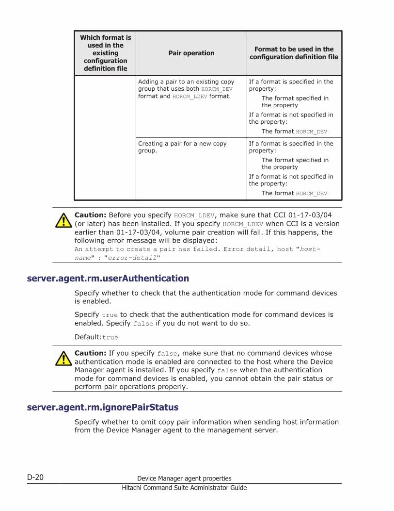
Which format isused in the
existingconfigurationdefinition file
Pair operation Format to be used in theconfiguration definition file
Adding a pair to an existing copygroup that uses both HORCM_DEVformat and HORCM_LDEV format.
If a format is specified in theproperty:
The format specified inthe property
If a format is not specified inthe property:
The format HORCM_DEV
Creating a pair for a new copygroup.
If a format is specified in theproperty:
The format specified inthe property
If a format is not specified inthe property:
The format HORCM_DEV
Caution: Before you specify HORCM_LDEV, make sure that CCI 01-17-03/04(or later) has been installed. If you specify HORCM_LDEV when CCI is a versionearlier than 01-17-03/04, volume pair creation will fail. If this happens, thefollowing error message will be displayed:An attempt to create a pair has failed. Error detail, host "host-name" : "error-detail"
server.agent.rm.userAuthenticationSpecify whether to check that the authentication mode for command devicesis enabled.
Specify true to check that the authentication mode for command devices isenabled. Specify false if you do not want to do so.
Default:true
Caution: If you specify false, make sure that no command devices whoseauthentication mode is enabled are connected to the host where the DeviceManager agent is installed. If you specify false when the authenticationmode for command devices is enabled, you cannot obtain the pair status orperform pair operations properly.
server.agent.rm.ignorePairStatusSpecify whether to omit copy pair information when sending host informationfrom the Device Manager agent to the management server.
D-20 Device Manager agent propertiesHitachi Command Suite Administrator Guide
Specify true to omit copy pair information. Specify false if you do not wantto omit the information.
In the following environments, make sure that you always specify true:
• Virtual machine for which a copy pair is assigned• An SVP is used as a virtual command device to manage copy pairs
defined as a device group.When P-VOLs and S-VOLs are assigned to the management server, thisproperty must be specified.
Default: false
server.agent.rm.horcmSourceIf the CCI configuration definition file is stored in a location other than thedefault, use the absolute path to specify the storage location of theconfiguration definition file.
Specify the path according the following rules:
• In Windows, use a forward slash (/) as a path delimiter.• In Windows, if a space is included in the path, you do not need to enclose
the path with quotation marks (").• Do not use symbolic links.
Default: None#
#: If you do not specify a path, the path for the following default storagelocation is used:
In Windows:System folder (represented by the environment variable %windir%)
In UNIX:/etc directory
Related topics
• Changing the storage location of the configuration definition file on page10-46
server.agent.rm.moduleTimeOutSpecify a timeout value for receiving command execution results when theDevice Manager agent executes a CCI command (in seconds).
When a command takes longer to execute than the specified value, theDevice Manager agent concludes that an error occurred during commandexecution.
Device Manager agent properties D-21Hitachi Command Suite Administrator Guide

This property should be changed only by a system administrator who hasexpert knowledge, when performance of the Device Manager agent's pairconfiguration functionality needs to be fine-tuned.
Default: 600 (seconds)
server.server.ssl.hdvmSpecify whether to use SSL to communicate between the Device Manageragent and the Device Manager server.
If SSL is used for communication, specify true. If SSL is not used forcommunication, specify false,
Default: false
server.http.server.timeOutSpecify a timeout value for receiving a response from the Device Managerserver, for example, when registering host information by executing theHiScan command, restarting the service, refreshing the host (in seconds).
If no response is received from the Device Manager server within thespecified time, the Device Manager agent concludes that an error hasoccurred and the HiScan command terminates abnormally.
Specify a value from 100 to 3,600. If the specified value is less than 100, thetimeout is assumed to be 100. If the specified value is more than 3,600, thetimeout is assumed to be 3,600.
Default: 600
server.util.processTimeOutSpecify the Device Manager agent's normal execution time for externalprograms (in milliseconds).
If an external program takes longer than the specified time, the DeviceManager agent concludes that an error has occurred and terminates theprogram. If you specify too short a time period, the Device Manager agentmight stop execution of external programs that are running regularly. Do notedit this property without current knowledge of the Device Manager agent'sperformance.
Default:600000
server.agent.evtwait.timeoutSpecify the waiting time until the status becomes pair when a remote pair isrestored (in seconds).
If the specified time has elapsed, the processing ends with an error.
Specify a value from 1 to 1999999.
D-22 Device Manager agent propertiesHitachi Command Suite Administrator Guide

Default:3600
Properties for command devices connected to DeviceManager agent (rgcmddev.properties file)
If the storage system is VSP G1000, Virtual Storage Platform, or HUS VM,and resources in the storage system are partitioned, in thergcmddev.properties file, specify a resource pool of the default virtualstorage machine or a command device whose resource group ID is 0.
• In Windows:installation-folder-for-Device-Manager-agent\mod\hdvm\config\rgcmddev.properties
• In Linux:installation-directory-for-Device-Manager-agent/mod/hdvm/config/rgcmddev.properties
• In Solaris or HP-UX:/opt/HDVM/HBaseAgent/mod/hdvm/config/rgcmddev.properties
• In AIX:/usr/HDVM/HBaseAgent/mod/hdvm/config/rgcmddev.properties
Devine the command device in the following format. If you define multiplecommand devices, only the command device defined in the last line becomesvalid.
RAID-ID.serial-number.LDEV-number
RAID-IDSpecify the storage system in the following format:
¢ R800 for VSP G1000¢ R700 for Virtual Storage Platform¢ HM70 for HUS VM
serial-numberSpecify the serial number of the storage system by using a decimal (base10) number. For VSP G1000 or Virtual Storage Platform, specify a 5-digitnumber. For HUS VM, specify a 6-digit number including the model name.
LDEV-numberSpecify the CU:LDEV number of the command device by using ahexadecimal number. Specify a resource pool of the default virtualstorage machine or a command device whose resource group ID is 0.
Device Manager agent properties D-23Hitachi Command Suite Administrator Guide

D-24 Device Manager agent propertiesHitachi Command Suite Administrator Guide

Acronyms and abbreviations
The following acronyms and abbreviations might be used in this guide.
A
AESAdvanced Encryption Standard
APIApplication Program Interfaces
ASCIIAmerican Standard Code for Information Interchange
C
CHAChannel Adapter
CHAPChallenge Handshake Authentication Protocol
CIDRClassless Inter-Domain Routing
CIMCommon Information Model
CIMOMCIM Object Manager
# A B C D E F G H I J K L M N O P Q R S T U V W X Y Z
Acronyms-1Hitachi Command Suite Administrator Guide

CLICommand Line Interface
CLPRCache Logical PaRtition
CNCommon Name
CPUCentral Processing Unit
CSRCertificate Signing Request
CSVComma Separated Value
CUControl Unit
CVSCustom Volume Size
D
DBMSDataBase Management System
DCRDynamic Cache Residency
DERDistinguished Encoding Rules
DKCDisK Controller
DM-LUDifferential Management LU
DMPDynamic MultiPathing
# A B C D E F G H I J K L M N O P Q R S T U V W X Y Z
Acronyms-2Hitachi Command Suite Administrator Guide
DMTFDistributed Management Task Force
DNDistinguished Name
DNSDomain Name System
DoSDenial of Services
E
EVSEnterprise Virtual Server
F
FQDNFully Qualified Domain Name
FTPFile Transfer Protocol
G
GUIGraphical User Interface
H
HBAHost Bus Adapter
HTTPHyperText Transfer Protocol
HTTPSHyperText Transfer Protocol Secure
# A B C D E F G H I J K L M N O P Q R S T U V W X Y Z
Acronyms-3Hitachi Command Suite Administrator Guide

I
I/OInput/Output
IDIDentifier
IETFInternet Engineering Task Force
IOPSInput Output Per Second
IPInternet Protocol
IP-SANInternet Protocol Storage Area Network
IPFItanium® Processor Family
IPv4Internet Protocol Version 4
IPv6Internet Protocol Version 6
iSCSIInternet Small Computer System Interface
J
JARJava ARchiver
L
LANlocal-area network
# A B C D E F G H I J K L M N O P Q R S T U V W X Y Z
Acronyms-4Hitachi Command Suite Administrator Guide

LBALogical Block Addressing
LDAPLightweight Directory Access Protocol
LDEVlogical device
LDKCLogical DisK Controller
LULogical Unit
LUNLogical unit number
LUSELogical Unit Size Expansion
M
MCUMain Control Unit
MOFManaged Object Format
MUMultiple Unit
N
NASNetwork Attached Storage
NATNetwork Address Translation
NICNetwork Interface Card
# A B C D E F G H I J K L M N O P Q R S T U V W X Y Z
Acronyms-5Hitachi Command Suite Administrator Guide

NPIVN Port ID Virtualization
NTPNetwork Time Protocol
O
OSOperating System
P
P-VOLPrimary VOLume
PAPPassword Authentication Protocol
PDEVPhysical Device
PEMPrivacy Enhanced Mail
PIDProcess ID
PNGPortable Network Graphics
PPProgram Product
R
RADIUSRemote Authentication Dial-In User Service
RAIDRedundant Array of Independent Disks
# A B C D E F G H I J K L M N O P Q R S T U V W X Y Z
Acronyms-6Hitachi Command Suite Administrator Guide

RCURemote Control Unit
RDNRelative Distinguished Name
RFCRequest For Comments
RMIRemote Method Invocation
S
S-VOLSecondary VOLume
SANStorage Area Network
SCSISmall Computer System Interface
SEDStack Execution Disable
SIMService Information Message
SLPService Location Protocol
SLPRStorage Logical PaRtition
SMI-SStorage Management Initiative - Specification
SMTPSimple Mail Transfer Protocol
SNIAStorage Networking Industry Association
# A B C D E F G H I J K L M N O P Q R S T U V W X Y Z
Acronyms-7Hitachi Command Suite Administrator Guide

SNIA-CTPSNIA Conformance Testing Program
SNMPSimple network management Protocol
SPService Pack
SRVSeRVice
SSHSecure SHell
SSIDStorage Subsystem ID
SSLSecure Sockets Layer
SSOSingle Sign - On
SVPService Processor
T
TCPTransmission Control Protocol
TLSTransport Layer Security
U
UDPUser Datagram Protocol
URLUniform Resource Locator
# A B C D E F G H I J K L M N O P Q R S T U V W X Y Z
Acronyms-8Hitachi Command Suite Administrator Guide

V
V-VOLVirtual VOLume
W
WANWide Area Network
WBEMWeb - Based Enterprise Management
WWNWorldwide name
X
XMLeXtensible Markup Language
# A B C D E F G H I J K L M N O P Q R S T U V W X Y Z
Acronyms-9Hitachi Command Suite Administrator Guide

# A B C D E F G H I J K L M N O P Q R S T U V W X Y Z
Acronyms-10Hitachi Command Suite Administrator Guide

Index
Symbols
.truststore 4-32
A
accountconditions 3-14
account.lock.num 3-5acquiring
maintenance information on management server11-14
adding SVP to trusted zone 5-28agent.logger.loglevel D-6agent.logger.MaxBackupIndex D-6agent.logger.MaxFileSize D-6agent.properties file D-3agent.rm.everytimeShutdown D-3agent.rm.horcmInstance D-4agent.rm.horcmRange D-5agent.rm.horcmService D-5agent.rm.shutdownWait D-4agent.rm.TimeOut D-3agent.util.hpux.displayDsf D-7alerts 6-3
SNMP traps 6-5analyzing performance
Universal Replicator 5-20analyzing Universal Replicator performance
settings for Device Manager 5-23settings for Replication Manager 5-24settings for Tuning Manager 5-24system configuration 5-20
applying
certificate authority for Common Componentserver certificate 4-36certificate authority for Device Manager servercertificate 4-46certificate authority for Host Data Collectorserver certificate 4-58
authorization group 3-8
B
backing updatabase 9-2
BaseDN 3-17Blocking HTTP communications 4-95bridge
network settings 2-32built-in user 5-26
C
C/T Deltaanalyzing 5-20
central management method 1-35certificate
checking 4-75checking for Host Data Collector 4-77importing into Common Component 4-71importing into Device Manager server truststore
4-52importing into Host Data Collector 4-76
certificate signing requestcreating for Common Component 4-33creating for Device Manager server 4-45
Index-1Hitachi Command Suite Administrator Guide

creating for Host Data Collector 4-56certificates, acquiring 4-86checking connections
external authentication server 3-47external authorization server 3-47
CIM/WBEM 7-2enabling 7-5user account settings 7-4
cimxmlcpa.properties A-51cimxmlscpa.properties A-29, A-51Ciphers A-33client certificate
exporting for CIM client 4-121exporting for event indications 4-116importing for object operations 4-113importing into CIM client 4-121
client.properties A-28client.rmi.port A-29com.wbemsolutions.jserver.bindto A-51Common Component
log output 6-2ports 2-2
communication protocolchanging between Replication Manager serverand Device Manager server 4-75
Compute Systems Manager 1-34condition
message (warning banner) 4-2conditions
account 3-14LDAP search user account 3-42
config.xml file 5-19configforclient.xml file 5-19configuration definition file
changing storage location 10-46description conventions 10-32editing 10-30notes 10-47prerequisite environment 10-29supported parameter 10-31
configuringnetworks 1-6
connectingnotes and requirements for Storage NavigatorModular 2 5-2
copy pairprerequisite version of Device Manager agent1-58storage system requirements 1-53
system configuration 1-35copy pairs
central management method 1-35local management method 1-35managing (Device Manager agent) 10-7system requirements 1-34virtual command device server method 1-35
creating a report 5-34customizedsnmptrap.customizedSNMPTrapEnable
A-33customizedsnmptrap.customizelist A-34customizedsnmptrap.properties A-33
D
databasebacking up 9-2exporting 9-19, 9-20importing 9-22, 9-25migrating 9-16restoring 9-6
database.properties file A-16, B-8dbm.startingCheck.retryCount A-17dbm.startingCheck.retryPeriod A-17dbm.traceSQL A-17, B-8Device Manager
IPv6 environments 2-33Device Manager - Storage Navigator
backing up settings 5-31downloading settings 5-32setting time periods 5-29
Device Manager agent 1-4acquiring maintenance information [host] 11-19environment settings 10-3firewall 10-6ports 2-7prerequisite version 1-58property files D-2reinstalling after host OS upgrade 10-2resident process 10-15
Device Manager agent servicechecking operating status 10-15starting 10-15stopping 10-15
Device Manager CLI 1-3changing password-encoding level 4-124enabling SSL/TLS 4-68
Device Manager server 1-4
Index-2Hitachi Command Suite Administrator Guide

enabling TLS/SSL 4-44ports 2-3property files A-3
devicemanager.properties file B-9dispatcher.properties A-20downloading
Device Manager server truststore file 4-65Tiered Storage Manager server truststore file4-69
downloading trace files,FD Dump Tool 5-49dvmcacerts 4-31Dynamic Link Manager 1-34
E
e-mail notificationssetting up 6-24
Element Managerdeleting settings for using 5-5settings 5-3
email alertscustomizing templates 6-9receiving 6-6registering recipients 6-7setting up SMTP server 6-7
enablingTLS/SSL for Device Manager server 4-44two-way authentication for event indications4-116two-way authentication for object operations4-112
enabling SSL/TLSDevice Manager CLI computer 4-68Tiered Storage Manager CLI computer 4-70
encryption typesKerberos authentication 3-50
environment settingsDevice Manager agent 10-3
event notificationcustomizing template 6-14setting properties 6-14specifying SMTP user authentication information
6-19using 6-13
exauth.properties fileKerberos server 3-34LDAP directory server 3-19RADIUS server 3-26
exception registrationHost Data Collector service 2-30, 2-31
exportingclient certificate for a CIM client 4-121client certificate for event indications 4-116databases 9-19, 9-20Device Manager server self-signed certificate4-66server certificate for a CIM client 4-121server certificate for object operations 4-111
external authentication server 3-7checking connections 3-47registering 3-17
external authorization server 3-7checking connections 3-47registering 3-17
F
FD Dump Tooldownloading trace files 5-49
file servers 1-12firewall
Device Manager agent 10-6Host Data Collector 2-30registering exceptions 2-15registering exceptions in Linux 2-15registering exceptions in Windows 2-15settings 2-15
flat model 3-16
G
Global Link Manager 1-34global-active device 1-65GUI 1-3
H
hbsa_modinfo command 10-17hbsa_util command 10-19hbsasrv command 10-15hcmds64banner
command 4-3, 4-4hcmds64getlogs command 11-14hcmds64unlockaccount command 3-6hdc.adapter.adapterProcessNum C-3hdc.adapter.esx.timeout C-7
Index-3Hitachi Command Suite Administrator Guide

hdc.adapter.localport C-3hdc.classloader A-40hdc.common.http.serverPort C-4hdc.common.https.serverPort C-6hdc.common.rmi.registryPort C-3hdc.common.rmi.serverPort C-4hdc.common.rmi.ssl.registryPort C-5hdc.common.rmi.ssl.serverPort C-5hdc.request.timeout A-38hdc.rmiregistry A-39hdc.rmiserver A-39hdc.service.fileCleanup.startTime C-7hdc.service.localport C-3hdc.service.rmi.registryIPAddress C-6hdc.ssl.ciphers C-11hdc.ssl.esx.certCheck C-8hdc.ssl.secure C-7hdc.usessl A-41hdcbase.properties C-11hdcbase.properties file C-2
Host Data Collector C-11hdccacerts 4-32hdvm.analytics.disabled A-45hdvm.analytics.healthcheck.notification.exportreport.locale A-45hdvm.port B-9hdvm.protocol B-9hdvm.replication.disabled A-50hdvm.rmi.port B-9hdvm.timeout B-9hdvm_info command 10-19hdvmagt_setting command 10-20hdvmcacerts 4-32hdvmmodmailuser command 6-8, 6-19hdvmmodpolluser command 7-14hierarchical structure model 3-15HiScan command 10-22Hitachi Command Suite common trace log
setting up 6-2Hitachi File Services Manager 1-34Hitachi Storage Services Manager 1-34
launching 5-25hldutil command 10-24hldutil.properties file D-7HORCM_CMD 10-35HORCM_DEV 10-37HORCM_INST 10-42HORCM_INSTP 10-44HORCM_LDEV 10-40
HORCM_MON 10-33HORCM_VCMD 10-37host 1-4
that can be managed by Device Manager 1-12Host Data Collector 1-4
acquiring maintenance information 11-17acquiring maintenance information [host] 11-18firewall 2-30ports 2-5property files C-2resident process 8-8
Host Data Collector servicechecking operating status 8-10exception registration 2-30, 2-31starting 8-9stopping 8-9
host management software 1-13host.agent.access.timeoutForRpm A-38host.mf.agent.connection.timeout A-38host.properties file A-37hostdatacollectors.properties A-38htmsetup command 5-18
in cluster environment 5-16in non-cluster environment 5-15
htnm.flashMode A-45htnm.infoAcquirePeriod A-43htnm.server.n.host A-44htnm.server.n.port A-45htnm.server.n.protocol A-45htnm.servers A-44HtsmgetTI.properties file 11-16htsmmodmailuser command 6-21HTTPPort A-52HTTPSPort A-52
I
importingcertificate into Common Component 4-71certificate into Device Manager server truststore
4-52certificate into Host Data Collector 4-76client certificate into CIM client 4-121databases 9-22, 9-25Host Data Collector server certificate intokeystore 4-59server certificate for event indications 4-117server certificate for object operations 4-113
Index-4Hitachi Command Suite Administrator Guide

server certificate into CIM client 4-121server certificate into Device Manager agent4-79server certificate into Device Manager serverkeystore 4-47server certificate into Web browser 4-66
indtruststore 4-33IPv6
global address 2-34global-unique local address 2-34link-local address 2-34linking with storage systems that support IPv6
2-35migrating Device Manager server 2-34site-local address 2-34
J
Javachanging (Device Manager agent) 10-4changing (Host Data Collector) 1-11
javaconfig.properties file C-10javapath_setup command 10-4javapathlocation C-11JDK
changing 1-10jserver.properties A-51jssecacerts 4-30
K
Kerberos authenticationencryption types 3-50
Kerberos serverexauth.properties file 3-34
key pairchanging password of Device Manager server4-50creating for CIM client 4-120creating for Device Manager server 4-41creating for Host Data Collector 4-56deleting from Device Manager server keystore4-50viewing in normal mode (Device Managerserver) 4-48viewing in verbose mode (Device Managerserver) 4-49
keystore
changing password of Device Manager server4-51Importing a Host Data Collector servercertificate 4-59
keystore filecreating for event indications 4-113creating for object operations 4-109
L
launchapp.elementmanager.role.mode A-37launchapp.elementmanager.usehostname A-37launchapp.properties A-35launchapp.snm2.rmi.port A-36launchapp.snm2.url A-36launching
Hitachi Storage Services Manager 5-25LDAP directory server
condition for server certificate 4-74exauth.properties file 3-19
LDAP search userregistering 3-43
LDAP search user account 3-41checking 3-45conditions 3-42deleting 3-45
ldapcacerts 4-31Linux
registering firewall exceptions 2-15local management method 1-35locking
System account 3-5unlocking accounts 3-6user accounts 3-4
logger.guiMessageFileCount B-13logger.guiMessageMaxFileSize B-14logger.guiTraceFileCount B-13logger.guiTraceMaxFileSize B-14logger.hicommandbase.loglevel A-19logger.hicommandbase.MaxBackupIndex A-19logger.hicommandbase.MaxFileSize A-20logger.hicommandbase.sysloglevel A-19logger.iotrace.maxFileSize C-10logger.iotrace.numOfFiles C-10logger.loglevel A-18, D-8logger.MaxBackupIndex A-18, D-9logger.MaxFileSize A-18, D-9logger.messagelogLevel B-10
Index-5Hitachi Command Suite Administrator Guide

logger.properties A-17, C-9logger.properties file B-10, D-8logger.serverMessageFileCount B-12logger.serverMessageMaxFileSize B-14logger.serverTraceFileCount B-12logger.serverTraceMaxFileSize B-14logger.syslogLevel B-12logger.trace.level C-9logger.trace.maxFileSize C-9logger.trace.numOfFiles C-9logger.tracelogLevel B-11logging in 5-27logs
setup 6-1
M
mail-alert-detection.txt file 6-10mainframe hosts 1-12mainframe volumes 1-28maintenance information
acquiring on management server 11-14Host Data Collector 11-17host managed by Device Manager agent 11-19host managed by Host Data Collector 11-18
Management client 1-3Management server 1-3management server
changing host name 2-36changing IP address 2-38
managinghost 1-12
memory heap sizechanging 1-9
migratingdatabases 9-16Device Manager to IPv6 environment 2-34
migration.dataErase.defaultValue A-42migration.multiExecution A-43migration.plan.candidateCapacityGroupDisplayMaxCount A-42migration.plan.candidateVolumeCountLimit A-42migration.properties A-41migration.volumeDelete.defaultValue A-43mime.properties A-28MOF file
editing for event indications 4-114editing for object operations 4-110
N
namespace 7-4network
bridge 2-32NIC
network settings multiple NICs 2-32normal host 1-12
prerequisites (Device Manager agent) 1-16prerequisites (Host Data Collector) 1-14
O
open hosts 1-12OutOfMemory error 11-10
P
Pair management server 1-4pair management server 1-35parameter
configuration definition file 10-31password
truststore for Device Manager agent 4-81truststore for Host Data Collector 4-78
password.check.userID 3-3password.min.length 3-2password.min.lowercase 3-3password.min.numeric 3-3password.min.symbol 3-3password.min.uppercase 3-2performance information
settings for acquiring 7-9, 7-14storage system (CIM/WBEM functions) 7-7storage systems 5-6system configuration 7-7
pop-up blockerchanging settings 4-67
portschanging 2-10changing (CIM/WBEM) 7-6registering exceptions 2-15used by Common Component 2-2used by Device Manager agent 2-7used by Device Manager server 2-3used by Host Data Collector 2-5used by storage systems 2-7used by Tiered Storage Manager server 2-5
Index-6Hitachi Command Suite Administrator Guide

prerequisite environmentusing configuration definition file 10-29
prerequisitesnormal host (Device Manager agent) 1-16normal host (Host Data Collector) 1-14virtual machine (Device Manager agent) 1-20virtual machine (Host Data Collector) 1-17virtualization server 1-26
programproductinfo.properties file D-10properties
changing (Host Data Collector) C-2Device Manager server, changing A-4
properties (Device Manager agent)changing D-2
properties (Tiered Storage Manager server)changing B-2
property filesagent.properties D-3cimxmlscpa.properties A-29client.properties A-28customizedsnmptrap.properties A-33database.properties A-16, B-8Device Manager agent D-2Device Manager server A-3devicemanager.properties B-9dispatcher.properties A-20hdcbase.properties C-2hldutil.properties D-7Host Data Collector C-2hostdatacollectors A-38javaconfig.properties C-10launchapp.properties A-35logger.properties A-17, B-10, C-9, D-8migration.properties A-41mime.properties A-28programproductinfo.properties D-10server.properties A-5, B-3, B-15syntax rules A-4, B-3Tiered Storage Manager server B-2tuningmanager.properties A-43
R
RADIUS serverexauth.properties file 3-26
raidinf add report 5-37raidinf command 5-35raidinf delete report 5-38, 5-39
raidinf get reportinfo 5-40receiving
email alerts 6-6registering
recipients of email alerts 6-7remote connection
Tuning Manager (in a non-cluster environment)5-15
Tuning Manager (in cluster environment) 5-15Replication Manager 1-34Replication Manager server 1-4replication.properties file A-46Report Configuration Tool Command Reference5-34requirements
connecting to Storage Navigator Modular 2 5-2resident process 8-2
Device Manager agent 10-15Host Data Collector 8-8
restoringdatabase 9-6
rgcmddev.properties file D-23rpmlib.properties file A-50rpmlib.rpm.port A-50
S
secret keycreating for Common Component 4-33
securityconfiguring networks (common security risks)1-6
self-signed certificatechecking for CIM server 4-118creating for CIM client 4-120creating for Common Component 4-33creating for Device Manager server 4-41exporting 4-66for object operations 4-119
sendingSNMP traps to log files 6-11
server certificateapplying to certificate authority for CommonComponent 4-36applying to certificate authority for DeviceManager 4-46applying to certificate authority for Host DataCollector 4-58
Index-7Hitachi Command Suite Administrator Guide

checking for Device Manager agent 4-81conditions for LDAP directory 4-74deleting from Device Manager server truststore
4-54deleting from truststore for Device Manageragent 4-82exporting for CIM client 4-121exporting for object operations 4-111importing for event indications 4-117importing into CIM client 4-121importing into Device Manager agent 4-79importing into Device Manager server keystore
4-47importing into keystore for Host Data Collector
4-59importing into Web browser 4-66
server.agent.differentialrefresh.manual.enabledA-15server.agent.differentialrefresh.periodical.enabled
A-16server.agent.evtwait.timeout D-22server.agent.JRE.location D-13server.agent.maxMemorySize D-12server.agent.port D-11server.agent.rm.centralizePairConfiguration D-15server.agent.rm.cuLdevForm D-16server.agent.rm.exclusion.instance D-16server.agent.rm.horcm.poll D-17server.agent.rm.horcmSource D-21server.agent.rm.ignorePairStatus D-20server.agent.rm.location D-16server.agent.rm.moduleTimeOut D-21server.agent.rm.optimization.userHorcmFile D-17server.agent.rm.pairDefinitionForm D-18server.agent.rm.temporaryInstance D-18server.agent.rm.temporaryPort D-18server.agent.rm.userAuthentication D-20server.agent.shutDownTime D-13server.base.home A-8server.base.initialsynchro A-9, B-5server.checkOutVolumeRange B-7server.cim.agent A-9server.cim.http.port A-10server.cim.https.port A-11server.cim.support A-9server.cim.support.job A-10server.cim.support.protocol A-10server.configchange.enabled A-11server.dispatcher.configchange.pollingPeriod A-22
server.dispatcher.daemon.autoSynchro.dayOfWeekA-24
server.dispatcher.daemon.autoSynchro.doRefreshA-23
server.dispatcher.daemon.autoSynchro.intervalA-25server.dispatcher.daemon.autoSynchro.logicalGroup.doRefresh A-27server.dispatcher.daemon.autoSynchro.performance.doRefresh A-26server.dispatcher.daemon.autoSynchro.performance.startTime A-27server.dispatcher.daemon.autoSynchro.startTime
A-25server.dispatcher.daemon.autoSynchro.type A-24server.dispatcher.daemon.configUpdate.detection.interval A-22server.dispatcher.daemon.configUpdate.detection.variable.enabled A-25server.dispatcher.daemon.logicalGroupMappingUpdate.startTime A-28server.dispatcher.daemon.pollingPeriod A-21server.dispatcher.daemon.receiveTrap A-21server.dispatcher.daemon.replication.config.doUpdate A-46server.dispatcher.daemon.replication.config.minute A-48server.dispatcher.daemon.replication.config.offset
A-47server.dispatcher.daemon.replication.config.updateInterval A-47server.dispatcher.daemon.replication.performance.rpm.updateInterval A-48server.dispatcher.daemon.replication.performance.tnm.minute A-50server.dispatcher.daemon.replication.performance.tnm.offset A-49server.dispatcher.daemon.replication.performance.tnm.updateInterval A-49server.dispatcher.message.timeout A-20server.dispatcher.message.timeout.in.processing
A-20server.dispatcher.snm2.configchange.pollingPeriod
A-21server.dispatcher.traps.purgePeriod A-21server.eventMonitoringIntervalInMinute B-6server.eventNotification.mail.to A-14, B-6server.horcmconfigfile.hostname A-9server.http.entity.maxLength A-8, D-14
Index-8Hitachi Command Suite Administrator Guide

server.http.host A-5, D-11server.http.localPort D-11server.http.port A-6, D-11server.http.security.clientIP A-30, D-14server.http.security.clientIPv6 A-30server.http.security.unprotected A-31server.http.server.timeOut D-22server.http.socket.agentAddress D-11server.http.socket.bindAddress D-12server.https.enabledCipherSuites A-32server.https.port A-7server.https.security.keystore A-31server.https.security.truststore A-32server.logicalGroupMapping.updateInterval A-16server.logicalview.initialsynchro A-12server.mail.alert.status A-14server.mail.alert.type.storagesystem A-14server.mail.enabled.fileserver A-12server.mail.enabled.storagesystem A-12server.mail.errorsTo A-14, B-5server.mail.from A-13, B-5server.mail.smtp.auth A-13, B-6server.mail.smtp.host A-13, B-5server.mail.smtp.port A-13, B-6server.migration.dataErase.defaultValue B-7server.migration.maxRetryCount B-8server.migration.multiExecution B-6server.migrationPlan.candidateCapacityGroupDisplayMaxCount B-7server.migrationPlan.candidateVolumeCountLimit
B-7server.properties A-29server.properties file
Device Manager agent D-10Device Manager server A-5, A-29Tiered Storage Manager server B-3, B-15
server.rmi.port A-8, B-4server.rmi.secure B-15server.rmi.security.enabledCipherSuites B-15server.rmi.security.port B-4server.server.authorization D-14server.server.serverIPAddress D-14server.server.serverPort D-15server.server.ssl.hdvm D-22server.smisclient.indication.port A-15server.subsystem.ssid.availableValues A-15server.util.processTimeOut D-22service
changing user (Device Manager agent) 10-17
service processor 1-6setting up
SMTP server for email alerts 6-7settings
IPv6 2-33properties for event notification 6-14
shared secretchecking 3-47deleting 3-46registering 3-46
signed certificates 4-86SLP service
releasing 7-17starting and stopping 7-16
SMTP serversetting up for email alerts 6-7
SNMP trapsalerts 6-5sending to log files 6-11
specifyingSMTP user authentication information for eventnotification 6-19
SSL-encrypted communicationsblocking HTTP communications 4-95creating a private keypair 4-85creating a public keypair 4-85updating the certificate 4-87
storage locationconfiguration definition file, changing 10-46
Storage Navigator Modular 2linking 5-2
storage system 1-4acquiring performance information (by usingCIM/WBEM functions) 7-7changing 4-83requirements for managing copy pairs 1-53
storage systemscollecting performance information 5-6ports 2-7
SVP 1-6SVP, adding to trusted sites 5-28System account
automatically lock 3-5system configuration 1-3
central management method 1-40for acquiring performance information 7-7local management method 1-36managing copy pairs 1-35SVP configuration 1-48, 1-50
Index-9Hitachi Command Suite Administrator Guide

virtual command device server configuration1-44
system requirementsmanaging copy pairs 1-34
T
TIC command 11-19Tiered Storage Manager CLI 1-3
changing password-encoding level 4-124enabling SSL/TLS 4-70generating log file 11-16log file 11-16
Tiered Storage Manager server 1-4ports 2-5property files B-2
truststorechanging password for Device Manager agent4-81changing password for Host Data Collector 4-78deleting server certificate for Device Manageragent 4-82viewing in normal mode (Device Managerserver) 4-53viewing in verbose mode (Device Managerserver) 4-53
truststore filedownloading (Device Manager server) 4-65downloading (Tiered Storage Manager server)4-69
truststores 4-30Tuning Manager 1-34
remote connection (in a non-clusterenvironment) 5-15remote connection (in cluster environment) 5-15
tuningmanager.properties file A-43two-way authentication
disabling 4-119enabling for event indications 4-116enabling for object operations 4-112
U
Universal Replicatoranalyzing performance 5-20
user accountsaccount locking 3-3account locking policies 3-4
password policies 3-2setting account locking policies 3-4setting password policies 3-2unlocking accounts 3-6
user authenticationemail alerts 6-8event notification 6-19
user_httpsd.conf file 4-36using
event notification 6-13
V
veritas.volume.manager.version D-10virtual command device server 1-35virtual machine 1-12
prerequisites (Device Manager agent) 1-20prerequisites (Host Data Collector) 1-17tasks for changing configuration 1-25
virtualization server 1-12changing 4-79prerequisites 1-26
W
warning banner 4-2creating and registering a message 4-2deleting message 4-4message display condition 4-2
Web browseraccepting certificates 4-90
Windowsregistering firewall exceptions 2-15
Index-10Hitachi Command Suite Administrator Guide

Hitachi Command Suite Administrator Guide

Hitachi Data Systems
Corporate Headquarters2845 Lafayette StreetSanta Clara, California 95050-2639U.S.A.www.hds.com
Regional Contact Information
Americas+1 408 970 [email protected]
Europe, Middle East, and Africa+44 (0)1753 [email protected]
Asia Pacific+852 3189 [email protected]
MK-90HC175-16