Embed Size (px)
Citation preview

History of Astronomical Instruments
The early history:
From the unaided eye to telescopes

The Human Eye
Anatomy and
Detection Characteristics

Anatomy of the Human Eye


Sensitivity of the Eye's Cones and Rods
0
0.2
0.4
0.6
0.8
1
1.2
Wavelength [nm]
Re
lati
ve S
en
siti
vity
rods
cones
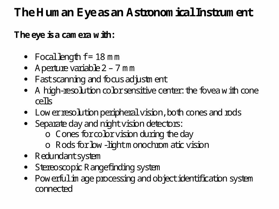
The Human Eye as an Astronomical Instrument The eye is a camera with:
Focal length f = 18 mm Aperture variable 2 – 7 mm Fast scanning and focus adjustment A high-resolution color sensitive center: the fovea with cone
cells Lower resolution peripheral vision, both cones and rods Separate day and night vision detectors:
o Cones for color vision during the day o Rods for low-light monochromatic vision
Redundant system Stereoscopic Rangefinding system Powerful image processing and object identification system
connected

Empirical Starting point: Experienced observers under ideal conditions can just barely see stars of 6 th magnitude. Calibration of the magnitude scale: A star of 0 magnitude in the visual band emits: 3.75 10-11 J m-2 s-1 nm-1
(Joules per square meter collecting area (0.38 10-4 m2), per second collecting time (0.15 s), and per nm filter bandpass (100nm) ) This makes 2.14 10-14 J of energy received by the eye in one reaction time.

Each photon carries an energy of hc/λ = 3.61 10-19 J This means the eye receives 59000 photons per second from the 0 magnitude star. A 6 mag star receives a factor of 251 less Photons, i.e. 235 photons The eye also receives 1711 competing photons From every square degree of the sky. Assume light from 0.1 square degrees actually interferes or competes with the detection of The star, i.e. 171 competing photons.

Quantum efficiency of the eye is about 5% under optimal conditions: Healthy eye, perfectly dark adapted, using peripheral(rod) vision, having enough oxygen, good nutrition (vitamin A), experienced in the mental evaluation of faint signals. Under these conditions, in the reaction time interval, we have: 12 photons detected from the star competing with 9 photons from the sky. The 12 photons have to be detected against a total noise of sqrt (12+9) = 4.6 photons. The 6 mag star is thus a 2.6 σ detection, which is just a quantitiative way of saying: “barely able to see it”

Resolving Power of the Eye Resolution (daylight viewing with fovea): 1 arcmin Projected diameter of fovea: 100 arcmins Sensor density: 30 106 rods / steradian = 2.7 rods/arcmin2
1.2 106 cones / steradian = 0.1 rods/arcmin2
In the fovea: 50 106 cones / steradian = 4.2 rods/arcmin2
Diameter of individual cones: 2 μm (25”)
Diameter of individual rods: 1 μm (12”)

Comparison to Diffraction Limit Pupil diameter: 2.5 mm Wavelength: 500 nm (green light) Diffraction Limit: 1.22 λ/d = 0.000244 radian = 0.84 arcmin Under optimal bright daylight conditions, the eye is capable of nearly diffraction-limited resolution. At night, the pupil is larger (up to 7 mm) and the resolution is limited by rod-cell density.
Visual Observations
• Navigation
• Calendars
• Unusual Objects (comets etc.)


Hawaiian Navigation:
From Tahiti to Hawaii
Using the North direction,
Knowledge of the lattitude,
And the predominant direction of the
Trade Winds
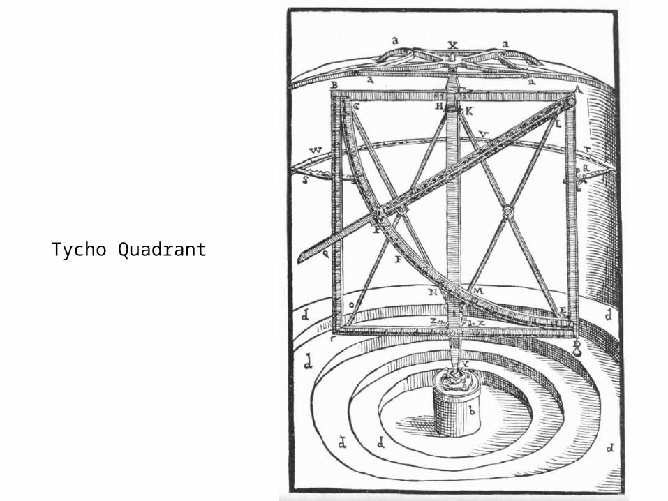
Tycho Quadrant

Pre-Telescopic Observations
• Navigation
• Calendar
• Astrology
• Planetary Motion
• Copernican System
• Kepler’s Laws

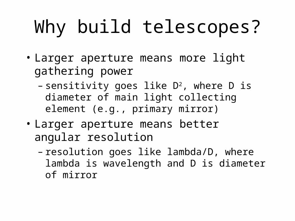
Why build telescopes?
• Larger aperture means more light gathering power– sensitivity goes like D2, where D is diameter of
main light collecting element (e.g., primary mirror)
• Larger aperture means better angular resolution– resolution goes like lambda/D, where lambda is
wavelength and D is diameter of mirror

Collection: Telescopes
• Refractor telescopes– exclusively use lenses to collect light– have big disadvantages: aberrations & sheer
weight of lenses
• Reflector telescopes– use mirrors to collect light– relatively free of aberrations– mirror fabrication techniques steadily improving

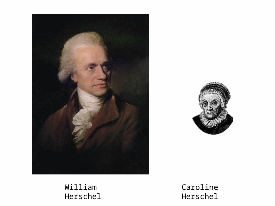
William Herschel Caroline Herschel

Herschel 40 ft Telescope

Optical Reflecting Telescopes
• Basic optical designs:– Prime focus: light is brought to focus by primary
mirror, without further deflection– Newtonian: use flat, diagonal secondary mirror to
deflect light out side of tube– Cassegrain: use convex secondary mirror to reflect
light back through hole in primary– Nasmyth focus: use tertiary mirror to redirect light to
external instruments
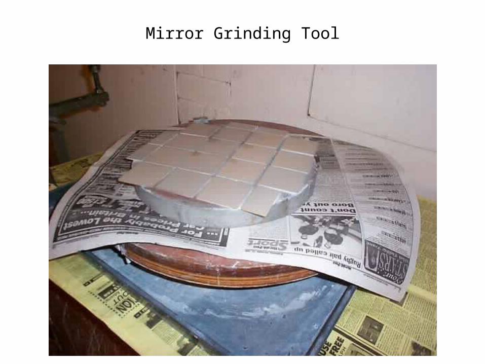
Mirror Grinding Tool

Mirror Polishing Machine

Fine Ground Mirror
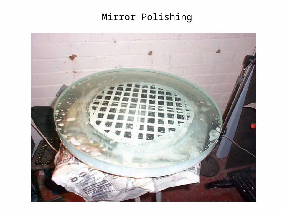
Mirror Polishing
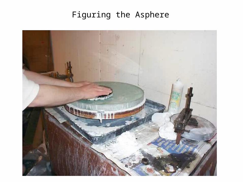
Figuring the Asphere


Crossley 36” Reflector

Yerkes 40-inch Refractor
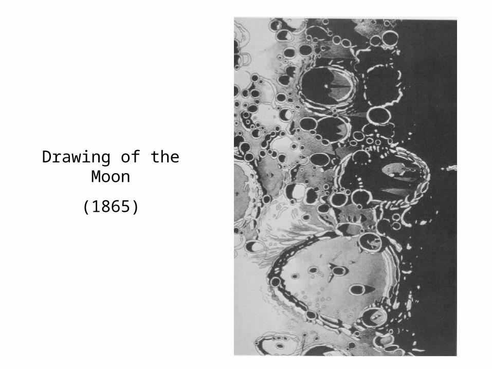
Drawing of the Moon
(1865)

First Photograph of the Moon (1865)
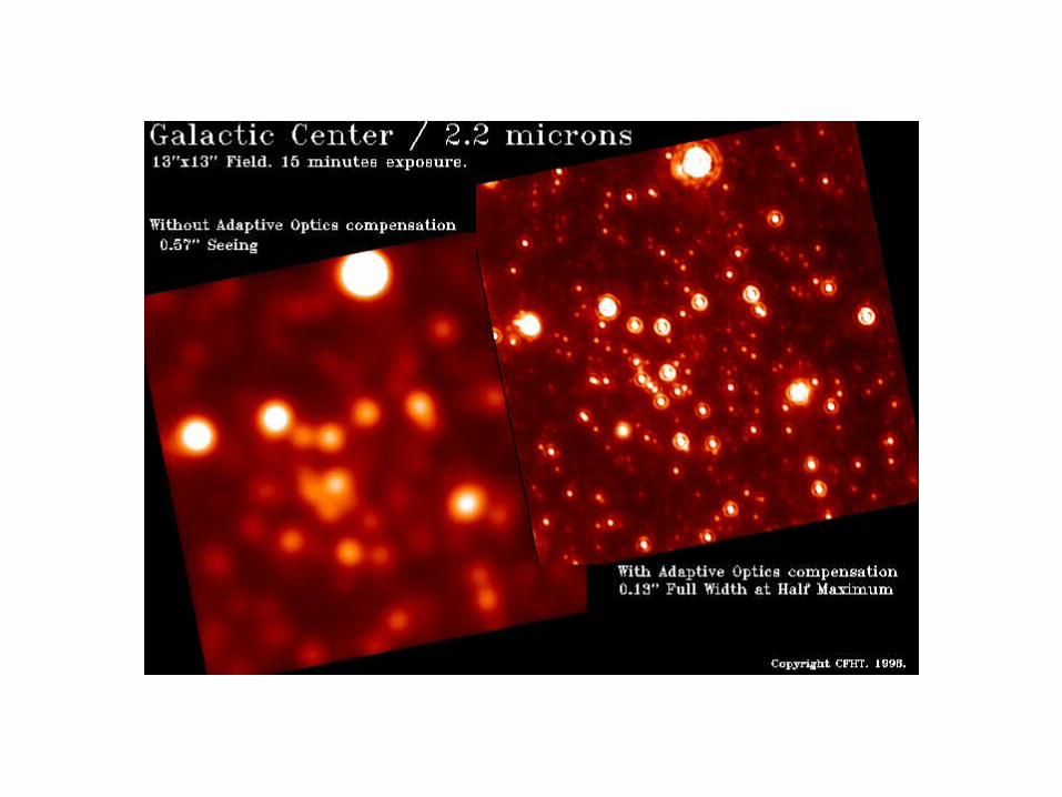
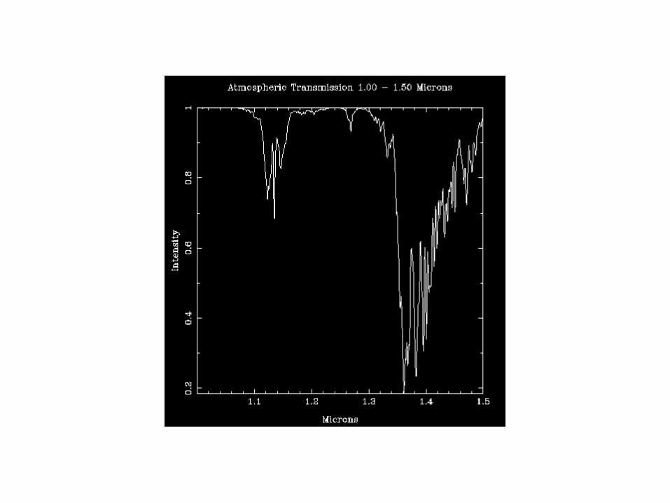
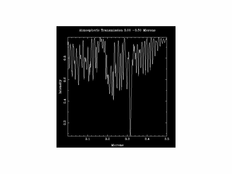
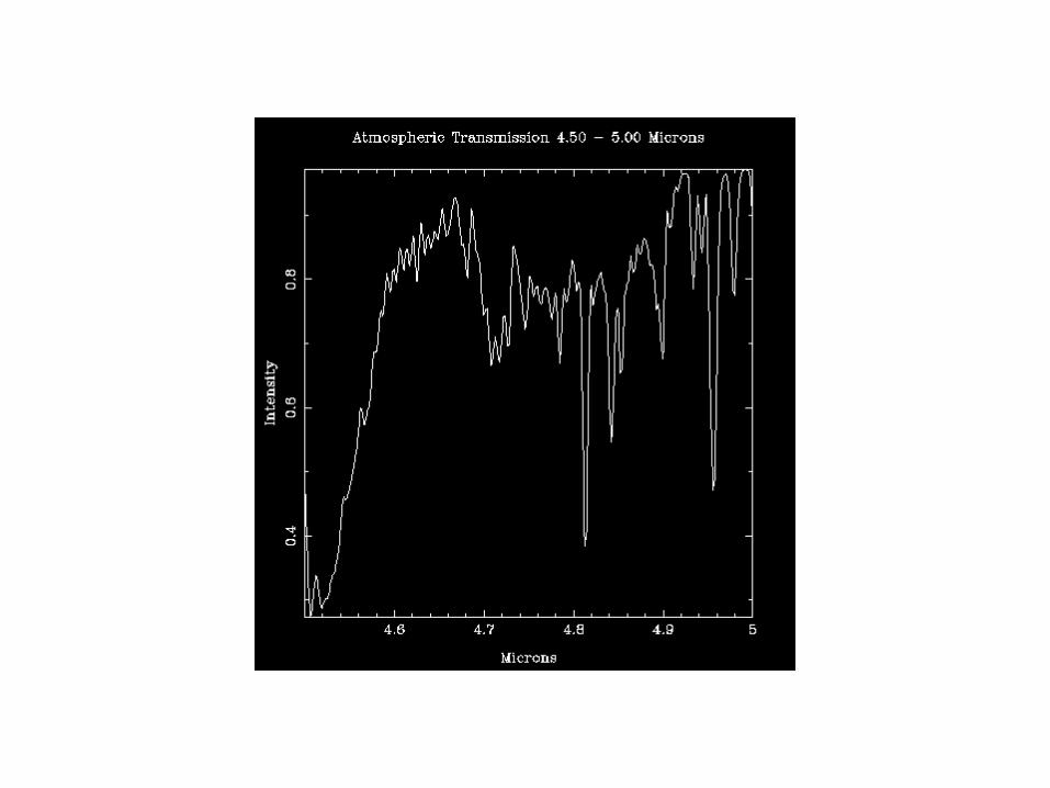
The Limitations of Ground-based Observations
Diffraction
Seeing
Sky Backgrounds
Diffraction
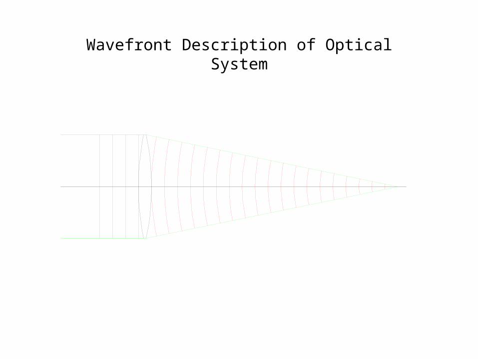
Wavefront Description of Optical System

Wavefronts of Two Well Separated Stars
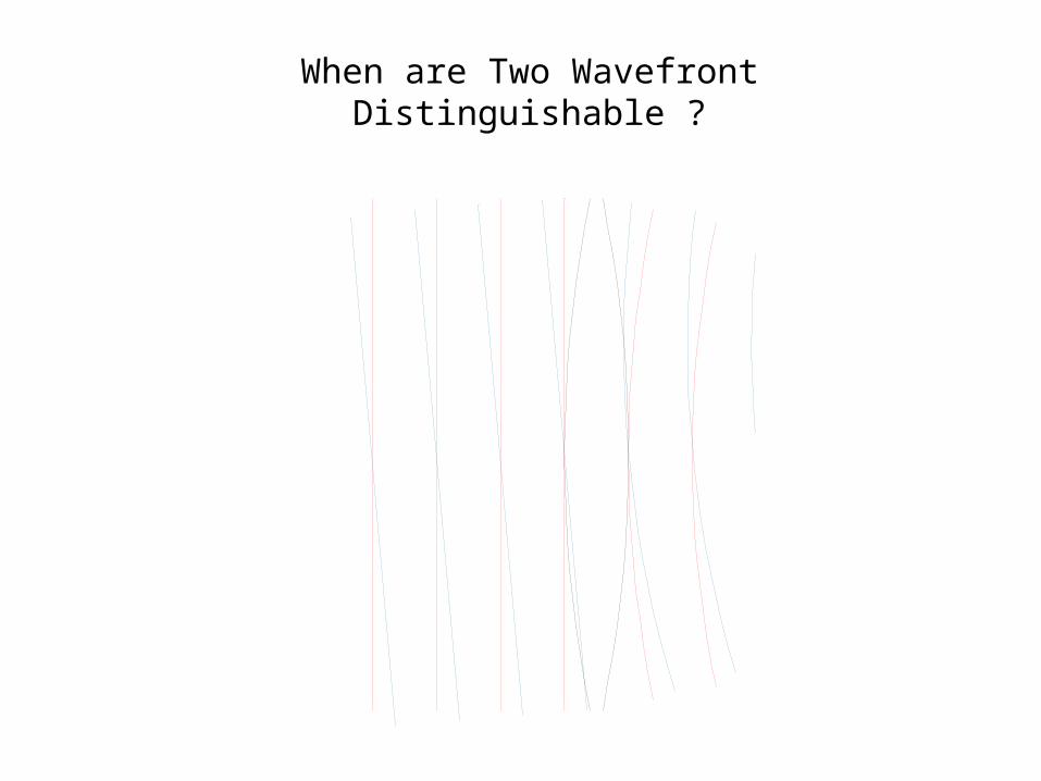
When are Two Wavefront Distinguishable ?
Atmospheric Turbulence

Characteristics of Good Sites
• Geographic latitude 15° - 35°
• Near the coast or isolated mountain
• Away from large cities
• High mountain
• Reasonable logistics
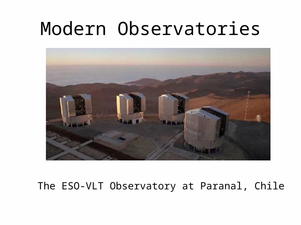
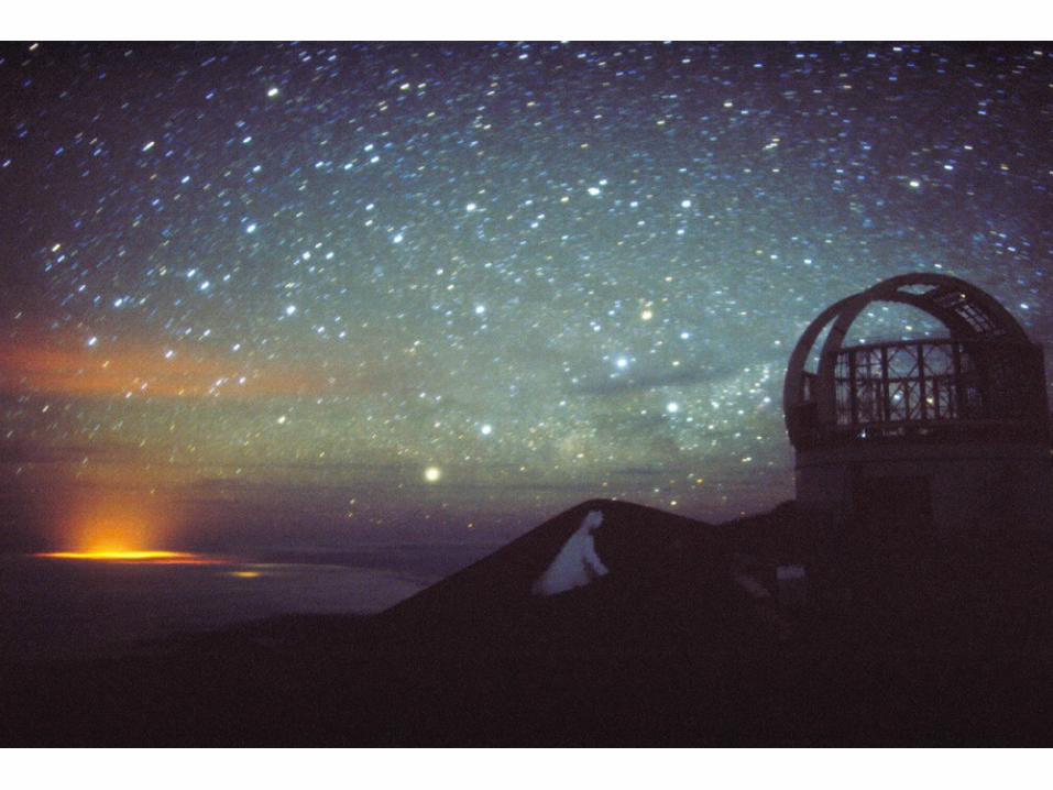
Modern Observatories
The ESO-VLT Observatory at Paranal, Chile


Pu`u Poliahu
UH 0.6-m
UH 0.6-m
UH 2.2-m
The first telescopes on Mauna Kea (1964-1970)

Local Seeing
Flow Pattern Around a BuildingIncoming neutral flow should enter
the building to contribute to
flushing, the height of the turbulent
ground layer determines the
minimum height of the apertures.
Thermal exchanges with the ground by re-circulation inside the cavity zone is
the main source of thermal turbulence
in the wake.

Mirror Seeing
When a mirror is warmer that the air in an undisturbed enclosure, a convective equilibrium (full cascade) is reached after 10-15mn. The limit on the convective cell size is set by the mirror diameter
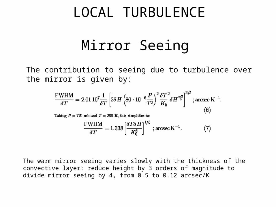
LOCAL TURBULENCE
Mirror Seeing
The warm mirror seeing varies slowly with the thickness of the convective layer: reduce height by 3 orders of magnitude to divide mirror seeing by 4, from 0.5 to 0.12 arcsec/K
The contribution to seeing due to turbulence over the mirror is given by:

Mirror Seeing
When a mirror is warmer that the air in a flushed enclosure, the convective cells cannot reach equilibrium. The flushing velocity must be large enough so as to decrease significantly (down to 10-30cm) the thickness turbulence over the whole diameter of the mirror.
The thickness of the boundary layer
over a flat plate increases with the
distance to the edge in the and
with the flow velocity.
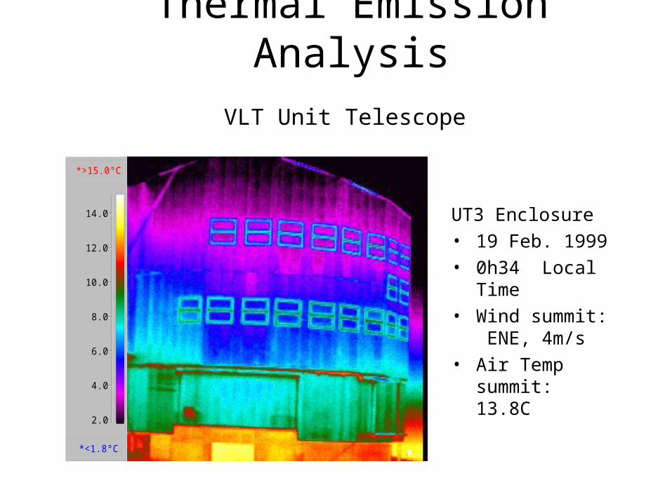
Thermal Emission Analysis
VLT Unit Telescope
UT3 Enclosure• 19 Feb. 1999• 0h34 Local
Time• Wind summit:
ENE, 4m/s• Air Temp
summit: 13.8C
*>15.0°C
*<1.8°C
2.0
4.0
6.0
8.0
10.0
12.0
14.0
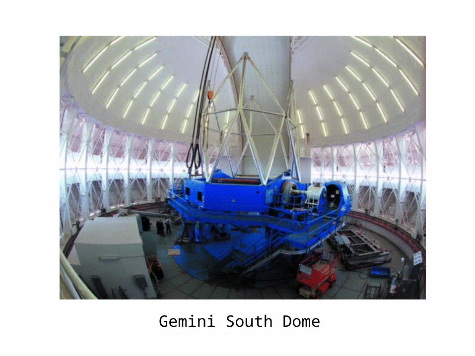
Gemini South Dome


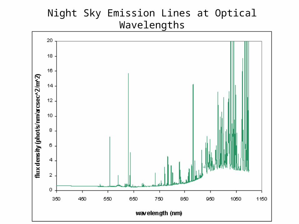
Night Sky Emission Lines at Optical Wavelengths
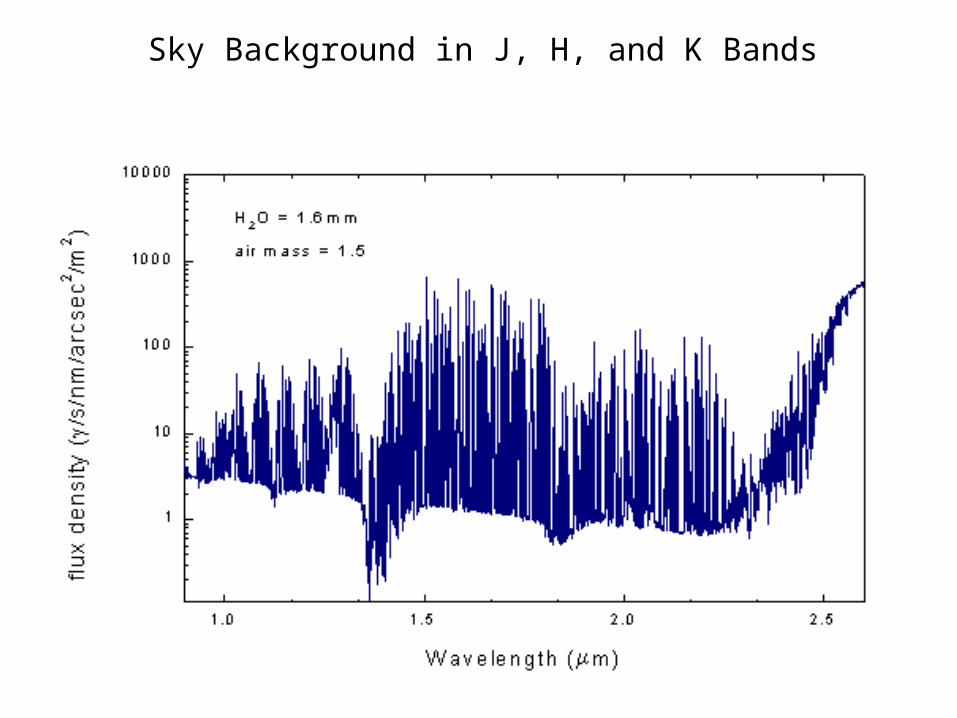
Sky Background in J, H, and K Bands
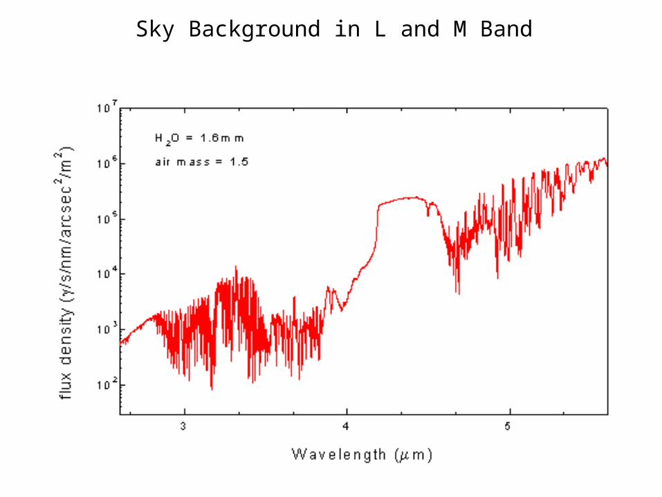
Sky Background in L and M Band

V-band sky brightness variations

H-band OH Emission Lines


Camera Construction Techniques 1.
Pre-amplifierPressure Vessel Vacuum pump port
Liquid Nitrogen fill port
Camera mountingFace-plate.
The photo below shows a scientific CCD camera in use at the Isaac Newton Group. It is approximately 50cm long, weighs about 10Kg and contains a single cryogenically cooled CCD.The camera is general purpose detector with a universal face-plate for attachment to varioustelescope ports.
Mounting clamp

Camera Construction Techniques 4.
...
A cutaway diagram of the same camera is shown below.
Thermally Electrical feed-through Vacuum Space Pressure vessel Pump PortInsulatingPillars
Foc
al P
lane
of
Tel
esco
pe
Te
lesc
op
e b
ea
m
Optical window CCD CCD Mounting Block Thermal coupling Nitrogen can Activated charcoal ‘Getter’
Boil-off
Face-plate

Camera Construction Techniques 5.
CCDTemperature servo circuit board
Platinum resistancethermometer
Gold plated copper mounting block
Top of LN2can
PressureVessel
Signal wires to CCDLocation points (x3)for insulating pillarsthat reference the CCDto the camera face-plate
Aluminised Mylarsheet
Retainingclamp
The camera with the face-plate removed is shown below
‘Spider’.The CCD mountingblock is stood off from the spider usinginsulating pillars.
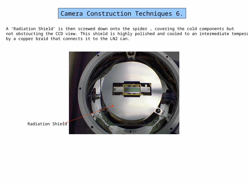
Camera Construction Techniques 6.
A ‘Radiation Shield’ is then screwed down onto the spider , covering the cold components butnot obstructing the CCD view. This shield is highly polished and cooled to an intermediate temperatureby a copper braid that connects it to the LN2 can.
Radiation Shield
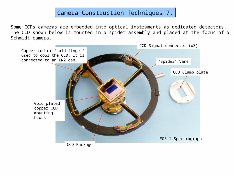
Camera Construction Techniques 7.
‘Spider’ Vane
CCD Clamp plate
CCD Signal connector (x3)Copper rod or ‘cold finger’used to cool the CCD. It isconnected to an LN2 can.
Gold plated copper CCD mounting block.
CCD Package
Some CCDs cameras are embedded into optical instruments as dedicated detectors.The CCD shown below is mounted in a spider assembly and placed at the focus of a Schmidt camera.
FOS 1 Spectrograph