Embed Size (px)
Citation preview

HISTORIC AMERICAN ENGINEERING RECORD
FORT BELVOIR RAILROAD BRIDGE
(Facility No. 1433)
HAER No. VA-141
LOCATION: Spanning U.S. 1, Accotink, Fairfax County, Virginia
DATE OF CONSTRUCTION: 1928, 1935
STRUCTURAL TYPE: Concrete arch and plate girder
DESIGNER/BUILDER: U.S. Army Quartermaster Corps, Virginia Bridge and Iron Company
PRESENT OWNER: U.S. Army
PREVOUS OWNER: U.S. Army
PRESENT USE: None
SIGNIFCANCE: The Fort Belvoir Railroad Bridge (Facility No. 1433) was constructed to support the Fort Belvoir Military Railroad. The current structure replaces an earlier crossing, Trestle 5, which was completed in 1918. By the mid-1920s, replacement of the trestle became necessary due to deterioration. The current bridge was completed in 1928, with modifications undertaken in 1935. The bridge is associated with the Fort Belvoir Military Railroad, which was constructed to support World War I mobilization efforts. The Virginia State Historic Preservation Office determined the bridge eligible for inclusion in the National Register of Historic Places in 2012.
AUTHORS: Kirsten Peeler, Senior Project Manager Kathryn M. Kuranda, Senior Vice President, Architectural and Historical Services R. Christopher Goodwin & Associates, Inc.
PROJECT INFORMATION: Documentation of the Fort Belvoir Military Railroad Bridge (Facility No.
1433) was undertaken in partial fulfillment of the stipulations contained in a Programmatic Agreement executed in November 2012 among the Department of Transportation Federal Highway Administration; United States Army Garrison, Fort Belvoir; County of Fairfax, Virginia; Commonwealth of Virginia Virginia Department of Transportation; Department of Defense Office of Economic Adjustment; Catawba Indian Nation; National Trust for Historic Preservation; Advisory Council on Historic Preservation; and Virginia State Historic Preservation Officer. HAER is administered by the Historic American Buildings Survey/Historic American Engineering Record, a division of the National Park Service, U.S. Department of the Interior

Fort Belvoir Railroad Bridge (Facility No. 1433)
HAER No. VA-141 Page 2
I. Geographical Information
The Fort Belvoir Military Railroad Bridge (Facility No. 1433) is part of the interior military railroad at Fort Belvoir and spans U.S. Route 1, which divides the North and South posts at the U.S. Army Garrison Fort Belvoir. The military installation is located on the southern tip of the Belvoir Peninsula in Fairfax County, Virginia. The 8,600-acre installation is located approximately 10 miles south of Alexandria, Virginia, and 20 miles south of Washington, D.C. (Fort Belvoir, Directorate of Public Works 2010:28). The alignment of the road predates the establishment of the installation.
II. Project Background
Documentation of the Fort Belvoir Military Railroad Bridge to Historic American Engineering Record (HAER) standards was undertaken in partial fulfillment of the stipulations contained in the Programmatic Agreement executed in November 2012 among the Department of Transportation Federal Highway Administration; United States Army Garrison, Fort Belvoir; County of Fairfax, Virginia; Commonwealth of Virginia Virginia Department of Transportation; Department of Defense Office of Economic Adjustment; Catawba Indian Nation; National Trust for Historic Preservation; Advisory Council on Historic Preservation; and Virginia State Historic Preservation Officer to mitigate effects to historic properties associated with the U.S. Route 1 improvement project. The agreement was executed pursuant to Section 106 of the National Historic Preservation Act of 1966, as amended. The Fort Belvoir Military Railroad Bridge (Facility No. 1433) will be removed as part of the U.S. Route 1 improvement project. The bridge was determined eligible for inclusion in the National Register of Historic Places by the Virginia State Historic Preservation Office in 2012 (Virginia Department of Historic Resources n.d.).
This documentation presents a historic context on the development of Fort Belvoir, military railroads, and Army logistics and warehousing during the twentieth century. A brief history of the construction of the Fort Belvoir Military Railroad and Facility No. 1433 are provided. The documentation concludes with a current description of Facility No. 1433.
III. Introduction
The Fort Belvoir Military Railroad was constructed to support World War I mobilization efforts and was begun in the winter of 1918. Construction work was completed by military engineers augmented by civilian employees. The approximately 4.51-mile railroad originally included six wood trestles; culverts also were constructed. The Fort Belvoir Military Railroad extended from the Quartermaster Corps warehouses located on the South Post to the north, terminating at Accotink Station (now Newington). The railroad ultimately linked the post to Alexandria and Washington, D.C, facilitating the movement of goods to the installation and troop movement between the installation and metropolitan centers.
Two of the original six wood trestles on the military railroad were replaced by reinforced-concrete bridges during the late 1920s. The replacement structures included Facility No. 1433, which spans U.S.

Fort Belvoir Railroad Bridge (Facility No. 1433)
HAER No. VA-141 Page 3
Route 1 and links the North Post to the South Post. The remaining original trestles were demolished and the ravines or crossings were infilled.
IV. Summary History of Fort Belvoir
Fort Belvoir (formerly Fort Humphreys) was established during the United States mobilization for World War I to provide training facilities for the Corps of Engineers. The camp was one of several established to train soldiers in the technical branches. As the United States prepared to enter World War I, the Army increased military engineer training activities. Existing training facilities at the Engineer School at Washington Barracks (now Fort McNair) in Washington, D.C., were insufficient and additional training sites were required.
Military officials looked south to Virginia and selected a rural location south of Alexandria and 20 miles south of Washington, D.C. The Virginia site, Camp Humphreys, fulfilled a number of selection criteria. The location afforded sufficient land for engineers to engage in land and water-based training opportunities. Camp Humphreys ultimately proved an ideal location for the practical training of military engineers in the construction of floating bridges; felling trees for construction projects; and the construction of bridges before heading to the front in France (U.S. House of Representatives 1919:6). Army officials intended the new site also to serve as the new home of the Engineer School.
Existing transportation networks influenced site selection. The Richmond, Alexandria, and Washington Road (U.S. Route 1) provided access to Washington, D.C. and important shipping ports. (Several names for U.S. Route 1 appear in the archival record, including the Richmond, Alexandria, Washington Road, the Richmond-Washington Road, the Washington-Richmond Road, the Fort Humphreys Washington Road, and the Robert E. Lee Highway. Unless specified otherwise, the Richmond, Alexandria, Washington Road will be used throughout this report.) Access to an existing rail line in the vicinity was a crucial factor in final site selection. The Richmond, Fredericksburg, & Potomac (RF&P) Railroad maintained a station at nearby Accotink. The Washington-Virginia Electric Railway Terminal at Mount Vernon also served the region. An established rail line facilitated efficient and rapid movement of troops and materials during an era when travel by automobile was unreliable and highway networks rudimentary. Final authorization for the establishment of the new military installation, Camp A. A. Humphreys, came on 18 December 1917 when Secretary of War Newton D. Baker authorized $3,300,000 for the construction of a 16,000-man cantonment (Peeler and Crosby 2010:53). By late April 1918, 200 officers and 6,200 soldiers were stationed at Camp Humphreys (“Fort Humphreys, Virginia” ca. 1930:17).
World War I mobilization efforts resulted in large-scale construction projects at Camp Humphreys. Facilities were needed to house the large number of troops stationed at Camp Humphreys for engineer training before deployment in Europe. Barracks, training facilities, and administrative buildings were constructed, often of temporary materials. Construction activities, which began in January 1918, also included the construction of a standard gauge (i.e., 4’ 8 ½”) railroad spur connecting the installation to the existing RF&P Railroad and a narrow gauge (i.e., any gauge less than 6”) internal railroad (Fort Belvoir Directorate of Public Works 2010:13). Warehouses were constructed to store supplies. The previously unpaved Richmond, Alexandria, and Washington Road (U.S. Route 1) was surfaced in concrete and a

Fort Belvoir Railroad Bridge (Facility No. 1433)
HAER No. VA-141 Page 4
plank road was built to connect the installation to the newly paved highway (Fort Belvoir Directorate of Public Works 2010:14).
At the conclusion of World War I, many Army posts established to support the war effort were declared excess property and subsequently closed. Camp Humphreys avoided closure due to the efforts of its former commandant, Colonel Richard Park; the former Constructing Quartermaster, Major Harold Kebbon; and Chief of Engineers Major General William Black. General Black sought to designate Camp Humphreys as the permanent home for the Engineer School. He enlisted the assistance of Colonel Park and Major Kebbon to achieve that goal. Ignoring Congressional directives to reduce military spending, camp officials continued construction activities during the immediate postwar years. Construction continued through 1919 in order to support the establishment of the new home for the Engineer School at Camp Humphreys (Peeler and Crosby 2010:54).
The War Department made the installation a permanent Army facility in 1922 with the official transfer of the Engineer School to the northern Virginia location. Designation as a permanent installation enabled permanent construction, i.e., the use of masonry materials, to proceed.
Additional construction funding for Fort Humphreys became available in 1926 when the Federal government sold excess military properties under a plan advocated by Secretary of War, John W. Weeks. The money generated from the sales was used to establish a specific funding pool, the Military Post Construction Fund, to support construction at select military installations. Fort Humphreys received funds from the program. A comprehensive design approach was developed for the new construction campaign, with the Colonial Revival style selected for all new buildings. During this construction period, the South Post attained its current design. Throughout the 1930s, Fort Belvoir continued to receive funding to construct barracks, senior officer housing, and non-commissioned officer family housing, in addition to administrative, educational, and recreational facilities (Peeler and Crosby 2010:55). The installation also underwent another name change during this period when General Order Number 1 was issued, renaming the installation Fort Belvoir on 14 February 1935 (Peeler and Crosby 2010:54).
Construction activities at Fort Belvoir again intensified in preparation for World War II. Wood-frame temporary and semi-permanent buildings were constructed to support the mobilization effort. Barracks, mess halls, warehouses, and officers’ quarters were built to accommodate 22,794 enlisted men and 1,548 officers (Peeler and Crosby 2010:55, 56). Once again, upon the conclusion of the war, many of the buildings constructed for the war effort were demolished.
Some military missions at Fort Belvoir were eliminated during the years immediately following the conclusion of World War II. However, the post gained additional missions during the Cold War period as the Federal government responded to the threat of communism. A major change occurred at Fort Belvoir when the Engineer School relocated to Fort Leonard Wood, Missouri, in 1988. Fort Belvoir’s mission expanded during the late twentieth century when it became host to tenants including, Fort Belvoir Community Hospital, the Defense Systems Management College, and the Defense Mapping School (Peeler and Crosby 2010:57).
Fort Belvoir Railroad Bridge (Facility No. 1433)
HAER No. VA-141 Page 5
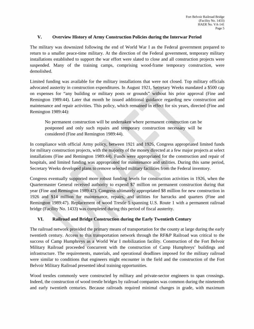
V. Overview History of Army Construction Policies during the Interwar Period
The military was downsized following the end of World War I as the Federal government prepared to return to a smaller peace-time military. At the direction of the Federal government, temporary military installations established to support the war effort were slated to close and all construction projects were suspended. Many of the training camps, comprising wood-frame temporary construction, were demolished.
Limited funding was available for the military installations that were not closed. Top military officials advocated austerity in construction expenditures. In August 1921, Secretary Weeks mandated a $500 cap on expenses for “any building or military posts or grounds” without his prior approval (Fine and Remington 1989:44). Later that month he issued additional guidance regarding new construction and maintenance and repair activities. This policy, which remained in effect for six years, directed (Fine and Remington 1989:44):
No permanent construction will be undertaken where permanent construction can be postponed and only such repairs and temporary construction necessary will be considered (Fine and Remington 1989:44).
In compliance with official Army policy, between 1921 and 1926, Congress appropriated limited funds for military construction projects, with the majority of the money directed at a few major projects at select installations (Fine and Remington 1989:44). Funds were appropriated for the construction and repair of hospitals, and limited funding was appropriated for maintenance and utilities. During this same period, Secretary Weeks developed plans to remove selected military facilities from the Federal inventory.
Congress eventually supported more robust funding levels for construction activities in 1926, when the Quartermaster General received authority to expend $7 million on permanent construction during that year (Fine and Remington 1989:47). Congress ultimately appropriated $8 million for new construction in 1926 and $14 million for maintenance, repairs, and utilities for barracks and quarters (Fine and Remington 1989:47). Replacement of wood Trestle 5 spanning U.S. Route 1 with a permanent railroad bridge (Facility No. 1433) was completed during this period of fiscal austerity.
VI. Railroad and Bridge Construction during the Early Twentieth Century
The railroad network provided the primary means of transportation for the county at large during the early twentieth century. Access to this transportation network through the RF&P Railroad was critical to the success of Camp Humphreys as a World War I mobilization facility. Construction of the Fort Belvoir Military Railroad proceeded concurrent with the construction of Camp Humphreys’ buildings and infrastructure. The requirements, materials, and operational deadlines imposed for the military railroad were similar to conditions that engineers might encounter in the field and the construction of the Fort Belvoir Military Railroad presented ideal training opportunities.
Wood trestles commonly were constructed by military and private-sector engineers to span crossings. Indeed, the construction of wood trestle bridges by railroad companies was common during the nineteenth and early twentieth centuries. Because railroads required minimal changes in grade, with maximum

Fort Belvoir Railroad Bridge (Facility No. 1433)
HAER No. VA-141 Page 6
inclines ranging from two to four per cent, structures such as bridges and trestles often were necessary in order to minimize extreme changes in grade (Alaska Railroad Corporation n.d.:10).
By the mid twentieth century, approximately 1,800 miles of wood trestles were in use in the country’s railways (Alaska Railroad Corporation n.d.:11). Private-sector engineers noted the many disadvantages of wood construction, even though its use in bridge and trestle construction was widespread. The disadvantages of wood included its lack of durability in comparison to steel or masonry, its ability to span shorter lengths in comparison to steel, and the fact that it is less fire resistant than other materials (Hool et al. 1942:372).
The typical service life of an untreated wood trestle was 20 to 30 years; frequent replacement of wood members was common due to failure (Alaska Railroad Corporation n.d.:11). Indeed, an ongoing program of selected repair and replacement of deteriorated elements was preferred “until such time as the general condition of the structure requires entire renewal” (American Railway Engineering Association 1921:295). Failure and repeated repairs often resulted in complete replacement of the trestle with other types of bridges or the spans were filled entirely (Alaska Railroad Corporation n.d.:11). Wood as a material used in bridge construction remained popular, despite its shortcomings. The major advantages of wood construction were its cost and availability (Hool et at. 1942:372).
Design of Military Railroads and Bridges
The Quartermaster Corps had a long history of developing standardized plans for both temporary and permanent Army construction. Beginning with the mid-nineteenth century, the Corps developed plans to guide all types of construction, including “headquarters buildings, barracks, electrical vaults, prisoner of war camps, railroad trestles and munitions storage” (U.S. Army Corps of Engineers 1997:6). The purpose of the plans was to assure uniformity in building type throughout the Army, regardless of location, and to promote economy and efficiency in construction.
The Army relied on standardized plans during periods of national emergencies, when rapid and efficient construction was required. During World War I and World War II mobilization efforts, a series of standardized plans for permanent and temporary construction were prepared. Construction guidance for World War I mobilization activities was presented in the Manual of the Construction Division of the Army. Section C. Engineer Division 1918. The manual, revised in 1919, was prepared by the Construction Division of the Army, and was “intended for use in connection with emergency work only” (War Department 1919:n.p.). The manual was developed “for the purpose of making generally available the fundamental principles and standards which have been adopted for emergency construction” (War Department 1919:1). The standards and drawings presented in the manual were “influenced by the emergency conditions requiring speed, economy of construction, and the conservation of certain materials” (War Department 1919:1). Constructing officers were encouraged to consult and use the standards and drawings presented in the manual before preparing new drawings (War Department 1919:1).
The 1918 manual included guidance on all aspects of camp construction. Drawings for the layout of cantonment grounds; the design and construction of warehouses and port terminals; and materials specifications were provided. In addition, the manual provided drawings for the layout and design of

Fort Belvoir Railroad Bridge (Facility No. 1433)
HAER No. VA-141 Page 7
railroad terminals and cantonment warehousing areas. General guidance on culverts, track laying, ballast, ties, and rails, among other railroad-related features, are included, and the efficacy of wood-trestle construction was recognized. Indeed, the manual’s discussion on crossings is brief, stating, “Wherever the railroad crosses a road or highway, a suitable crossing, similar to type shown on general plan, should be constructed” (War Department 1919:28). A wood trestle is the only type of crossing presented (Figure 1).
An engineer’s field manual titled, Professional Papers of the Corps of Engineers of the United States. Engineer Field Manual, also provided guidance on a variety of topics related to railroad construction including, survey and reconnaissance and the construction of railroads, roads, and bridges while in the field. Published in 1918, much of the bridge discussion presented in the field manual centers on the construction of wood trestles, although other types of bridges are examined, including Howe and Pratt trusses and suspension bridges. A limited discussion on railway bridges also is included.
The engineer’s field manual provided more detailed, technical advice on the construction of rail-related resources than the document prepared by the Construction Division. Guidance in the 1918 field manual stipulated the “kind of bridge to be built depends upon the load, the nature of the obstacle and the materials available” (emphasis in the original) (War Department 1918:147). The manual offered calculations for determining load; identified constants of strength and weight for a variety of species of wood; discussed the types of fastenings that should be used; and offered suggestions for the design of military bridges. The 1918 field guide suggested avoiding constructing on an incline; rather, the approaches to the bridge at each end “should be straight and nearly level for a distance equal to at least twice the maximum train length” (War Department 1918:242). Despite the wealth of guidance provided on the construction of military bridges in general, little technical expertise is presented on the construction of railway bridges. Discussion is limited to the placement of stringers, ties, and guardrails, and the recommended clear width (i.e., 14’) between trusses for the construction of a standard-gauge, single-track railroad (War Department 1918:242).
Private-Sector Railway Bridge Construction
The military’s guidance on bridge construction echoes similar contemporary advice from the private sector. The Manual of the American Railway Engineering Association. Definitions, Specifications and Principles of Practice for Railway Engineering published by the American Railway Engineering Association defined a railway trestle and discussed the advantages and disadvantages for its use. Specifications on appropriate trees for use in the construction of a trestle – a structure of upright members that support horizontal members used to support loads applied to the horizontal members – were provided (American Railway Engineering Association 1921:281). Wood trestles, which can encompass a frame trestle in which the upright members or supports are made of framed timbers, or a pile trestle, which the upright members are constructed of piles, were used to span gullies, valleys, and bodies of water. Wood was an abundant material that was less expensive than steel or masonry and did not require the same level of skill as the construction of a masonry structure.
In contrast to the manuals prepared by the Army, the civilian, private-sector manuals presented other options, including girder bridges, for spanning crossings. The 1921 manual also discussed plate girder bridges for spanning gullies and bodies of water. Plate girder bridges were recommended for use for spans from 30’ to 125’ (American Railway Engineering Association 1921:744). Plate girders were to be

Fort Belvoir Railroad Bridge (Facility No. 1433)
HAER No. VA-141 Page 8
spaced 6’-6” between centers (American Railway Engineering Association 1921:757). For girders used in deck bridges incorporating a single-track deck with a span 75’ or more, the girders were to be placed in the following manner (American Railway Engineering Association 1921:757):
The width center to center of girders or trusses shall be not less than one-fifteenth of the effective span, and not less than is necessary to prevent overturning under the assumed lateral loading. Panel lengths shall not exceed 1 ½ times the width c. to c. of trusses or girders (American Railway Engineering Association 1921:744) …but not less than7’-6” between centers (American Railway Engineering Association 1921:757).
The parts of the girder include: flange sections, web plates, flange rivets, flange splices, web splices, and end stiffeners (American Railway Engineering Association 1921:758,759). No such discussion occurs in military manuals.
In addition to guidance on bridge and trestle construction, the 1921 manual included insights on other rail-related construction, including general specifications and accepted industry standards on the production of the steel for rails and concrete for masonry bridges. The manual also specified material tests to verify performance for select materials. According to the manual, almost every part of the railroad should be marked. This included dating nails used in the ties, and branding of the ties, and the rail. Specifications for how and where the dates should be were provided (American Railway Engineering Association 1921:105). For rails, the date of manufacture, and in some cases, the manufacturer’s name, was to be identified (American Railway Engineering Association 1921:121).
Military Cooperation with Private-Sector Railroads during National Emergencies
Military railroads, that is, railroads owned and/or operated by the military, emerged as key components to World War I and World War II mobilization efforts. The military relied on the cooperation of the private-sector rail industry to assist with troop movement and supply shipments. Railroads were crucial to both war efforts, particularly during an age when road transportation was difficult and unreliable.
The War Department planned to coordinate with the American Railway Association for assistance during World War I (U.S. House of Representatives 1916:281). In his remarks before Congress, Maj. Gen. James B. Aleshire, Quartermaster General, did not specify the type of assistance the American Railway Association would provide. During same hearings, Army personnel presented then current capabilities for moving troops and equipment throughout the country. These capabilities are identified in Table 1.
Moving large numbers of troops and equipment had the potential to become logistically challenging. The railroads would be responsible for moving not just troops, but also supplies and industrial material, i.e., raw materials and manufactured products (U.S. House of Representatives 1916:283). Military use of the railroads would be competing with the private sector (U.S. House of Representatives 1916:283). However, priority for moving supplies and troops would be given to those trains with the most important cargo (U.S. House of Representatives 1916:283). The movement of supplies and troops would be divided into different trains, with each train carrying between 10 and 30 days’ supplies for the troops being transported by that particular train (U.S. House of Representatives 1916:283). The President of the United States was authorized, under Section 6 of the Act to Regulate Commerce, as amended, to demand that

Fort Belvoir Railroad Bridge (Facility No. 1433)
HAER No. VA-141 Page 9
troop transportation and material of war, be given preference and precedence during times of war or threatened war (U.S. House of Representatives 1916:285). The rail carriers “shall adopt every means within their control to facilitate and expedite the military traffic” (U.S. House of Representatives 1916:284).
During the early Cold War period, military planners assumed the railroads would continue to provide service in support of military actions as they did during World War I and, more recently, World War II (Behling 1961:203). By the 1960s, however, military officials recognized that the level of service provided by the railroads would be reduced. Significant improvements in transportation occurred since World War I. Increased competition from other types of transportation, i.e., trucks via highway and air transportation, meant the Federal government would not have to depend on the railroads as heavily as they did during previous large-scale mobilization efforts (Behling 1961:203).
Changes in the transportation and shipping industries adversely affect the railroads. By the mid twentieth century, the railroads were less competitive because the railroad companies had more expenses than their rival forms of transportation. Shipping companies, by truck, air, or water, could take advantage of publicly funded and maintained rights-of-way. By contrast, the railroad companies were responsible for maintaining their rail corridors (Behling 1961:204). Technical changes that included the use of heavier rail, which facilitated the use of heavier and faster trains, and the increased use of mechanical signaling devices increased single-track capacity by 75 to 80 per cent during the postwar period (Behling 1961:198). Revolutions in how freight was shipped also occurred during the period. The late 1950s saw the introduction of trailer-on-flat car, or “piggyback” whereby rail line transportation was combined with trucks used at pickup and delivery points (Behling 1961:198, 199). These changes in the railroad industry occurred during a period of reduced passenger ridership and a period of increased labor costs. As a railroad industry expert who spoke at a conference of private- and public-sector professionals cautioned, if another mobilization was required, as was the case during World War II, the rail industry would be insufficiently prepared to provide service (Behling 1961:202). According to this official, the rail industry had advance notice to prepare for World War II, and “substantial reserve of railroad capacity in equipment as well as in basic facilities” (Behling 1961:202). Unlike during World War II, according to this official, the railroads, in the postwar era of the late 1950s, no longer had a “similar reserve of equipment capability” (Behling 1961:202). Because the railroad industry in general was operating “for so long at the margins of financial stringency [it] is not in a position to provide any substantial reserve of capability to meet a sudden emergency” (Behling 1961:202).
Army Warehousing and Storage Capabilities Supporting Military Railroads
During both world wars, the Quartermaster Corps relied on a system of depots to distribute goods and supplies. Troops were moved to and from the front lines through the War Department’s ports of embarkation (Whelan at al. 1997:92). At the onset of World War I, the storage facilities at the Quartermaster Corps depots could not accommodate the large quantity of supplies needed to support the mobilization effort (Grandine and Cannan 1995:51). Additional storage buildings and warehouses were constructed to store necessary supplies. The depot system, which had been reorganized into geographic zones, supplied all camps and posts within a certain geographic area (Grandine and Cannan 1995:51). At the training camp level, numerous warehouses were constructed to store the vast quantities of supplies.

Fort Belvoir Railroad Bridge (Facility No. 1433)
HAER No. VA-141 Page 10
These warehouses were built with railroad sidings to facilitate supply shipments. Long, rectangular, wood-frame, single-story buildings with loading platforms were constructed.
During World War II, each technical branch maintained its own distribution systems as well as general depots (Whelan at al. 1997:92). The Quartermaster Corps began planning for the storage of supplies and materials and logistics in the event of another large-scale military action during the late 1930s. Although the Quartermaster Corps began plans to enlarge its existing 12 depots, these efforts were not realized until after the protective mobilization efforts were implemented in 1940 (Whelan at al. 1997:96). The Quartermaster Corps continued to expand its supply and warehousing facilities through May 1943 when the Army Service Forces halted all depot construction, except for extraordinary circumstances (Whelan at al. 1997:96).
VII. Summary History of the Construction of the Fort Belvoir Military Railroad
Access to existing railroads played a determining factor in site selection for Camp Humphreys as a training facility for organizing and training engineer replacement troops during World War I (Gray 1949:1). Construction of spurs from the steam railway operated by the RF&P Railroad at Accotink and the electric line Washington-Virginia Electric Railway Terminal at Mount Vernon provided the training camp with access to Washington, D.C. (Gray 1949:1). Ultimately, in addition to the railroad, six wood trestles were constructed to span crossings.
Land acquisition, survey, and construction of the Fort Belvoir Military Railroad were completed rapidly. The route for the railroad was finalized on 26 January 1918. A land acquisition plan was implemented in January 1918 and was completed by May 1918 for the approximately 100-foot wide right-of-way needed for the construction of the military railroad (Gray 1949:1). Survey work also began in January 1918 and was completed by May 1918. The government acquired the land for the railroad following negotiations with private property owners. Condemnation proceedings for the railroad right-of-way began in February 1918. Eventually, the Federal government was able to reach agreements with all but one of the affected property owners. The Acting Secretary of War approved the purchase of land for the railroad right-of-way for a cost of $10,227 on 22 November 1918 (U.S. House of Representatives 1920:706).
Construction of the standard-gauge railroad originally was under the auspices of the Construction Quartermaster, who had arranged the steam shovels, wagons, and scraper outfits and was drafting the construction contract (Park 1918:82). On 14 January 1918, the Construction Quartermaster was informed that the Engineer troops would handle all aspects of railroad construction, including the survey (Park 1918:82). Consequently, all arrangements with the construction contractor were cancelled (Park 1918:82). Military engineers, aided by civilian engineers, completed the survey work for the siting, profiles, and alignment of the military railroad (Gray 1949:2).
The Construction Division received orders in January 1918 to acquire stringer material, decking, and guard rails for 2,000 lineal feet of trestle (Park 1918:82). The camp commander concurrently ordered ties and Russian rail through the Director General of Military Railways (Park 1918:82, 83). Russian rail, which was made by the Cambria Steel Company from specifications provided by the Russian government also were ordered through the Director General of Military Railroads (Park 1918:11 Appendix XXIII (f)).

Fort Belvoir Railroad Bridge (Facility No. 1433)
HAER No. VA-141 Page 11
The rail ultimately proved less than ideal for American military use. The Russian rail was “not adapted for heavy motive power or equipment such as in use in standard gauge railroads in this country” (Park 1918:11 Appendix XXIII (f)). Duplicate materials were ordered from both the Director General of Military Railways and the Construction Quartermaster to ensure that sufficient materials were available to complete construction. The supplies ordered from the Construction Quartermaster arrived before those provided by the Director General of Military Railways (Park 1918:83).
Engineer troops, representing the numerous engineering trade schools, completed most of the work associated with railroad construction. The 304th Engineers started the work on the railroad. The 45th Engineers later replaced the 304th Engineers after the latter were deployed elsewhere (Park 1918:2 Appendix XXIII (f)). Initial work consisted of preparing the camp and obtaining the necessary tools and equipment to start construction (Gray 1949:4). Grading of the roadbed to the unloading siding at Accotink Village was completed by 18 March 1918 (Gray 1949:4). Civilians were used to assist with grading for the railroad. However, the contractor responsible for completing the grading experienced sever labor shortage, and in early May, military officials decided to replace all remaining civilian employees with soldiers (Park 1918:2 Appendix XXIII (f)). This action enabled the completion of all remaining grading to proceed at reduced costs (Park 1918:2 Appendix XXIII (f)). Troops completed the ballasting and track laying, and they also maintained and operated the railroad (“Fort Humphreys, Virginia” ca. 1930:19). Additionally, troops were responsible for constructing trestles and culverts.
Construction of the railroad proceeded under the supervision of Major Churchill of the 304th Engineers (U.S. Army Corps of Engineers 304th 1920:33). The Second Battalion of the 304th Engineers began construction from Accotink station and another group of engineers started work on the railroad from Camp Humphreys (U.S. Army Corps of Engineers 304th 1920:30). All work, including the construction located outside the military boundaries, fell under the control of the engineers in May. The 45th Engineers were responsible for work completed outside the installation boundaries, whereas replacement troops completed work on government property (Park 1918:3 Appendix XXIII (f)). By late July, the railroad was completed to the Quartermaster’s warehouses (Park 1918:3 Appendix XXIII (f)). When completed, the railroad extended from 23rd Street north to Accotink Station for a distance of approximately 4.51 miles (Gallager 1982:23).
Troops constructing the railroad were housed in temporary camps located at Camp Accotink, near Accotink Station, and others in the vicinity of the Belvoir cantonment (“Fort Humphreys, Virginia” ca. 1930:17). Engineer troops stationed at Camp Humphreys also participated in camp construction projects, in addition to railroad construction, prior to their deployment to France.
The undulating terrain, with its numerous ravines, required the construction of six trestles. Because the military training camp extended north and south of the existing Richmond, Alexandria, and Washington Road (U.S. Route 1), construction of a trestle over the road was necessary in order for supplies arriving at Accotink Station to the north to reach the Quartermaster warehouses at the southern end of the camp. Work on one trestle often was started by one regiment and completed by another. Construction on trestles 1, 2, and 3 was started by the 304th Engineers in February 1918; Trestle 4 was started by the 45th Regiment of Engineers in May 1918; and trestles 5 and 6 were started in March 1918 by the 102nd Regiment of Engineers (Park 1918:5 Appendix XXIII (f)). Ultimately, engineers from the various engineer training schools completed trestles 5 and 6 (Park 1918:3 Appendix XXIII (f)).

Fort Belvoir Railroad Bridge (Facility No. 1433)
HAER No. VA-141 Page 12
The design and construction of the trestles required skilled calculations by trained engineers. As recounted in the Official History of the Three Hundred and Fourth Engineer Regiment. Seventy-Ninth Division, U.S.A., the
largest of these [trestles] demanded nice calculation. This was designed by Capt. St. John, and was some 600 ft. long. It was on a 6⁰ curve and a 1.5% grade, and its two easement curves required especially accurate workmanship. The timbers for this bridge were measured, cut and placed by our men—some of the timbers were even hewn down and hauled from where they grew. Toward the end of the work, when extra speed was called for, a series of electric lights was installed around the trestle, and work was continued both day and night (U.S. Army Corps of Engineers 304th 1920:30).
The Second Battalion of the 304th Engineers left Virginia on 14 April 1918 (U. S. Army Corps of Engineers 304th 1920:33).The deployment of trained troops impacted construction and the Army relied on untrained troops to complete the work. The battalion constructing the railroad spur from Accotink to Camp Humphreys, for example, comprised immigrants from Philadelphia who had been drafted into the Army and who had limited engineering and railroad construction experience (Park 1918:84). Despite the challenging terrain and work conditions and a lack of experienced troops, the railhead ultimately reached the Camp Humphreys railroad terminal on 20 July 1919 (Park 1918:110). After construction, the railway operated ten passenger trains daily; handled 35 loads in and out, and carried troops (Park 1918:19 Appendix XXIII (f)).
The original requisition of motive power included: one U.S.E.D. steam locomotive No. 1 of the switch engine, 2-6-0 Mogul type; two RF&P Railroad locomotives of the 4-6-0 ten-wheeler type; and two 125 horsepower standard gauge gasoline locomotives (Gray 1949:6; Park 1918:13 Appendix XXIII (f)). The request for the two gasoline locomotives allowed for the release of the 4-6-0 locomotive for a 2-6-0 type (Gray 1949:6-7). Locomotive No. 1 purportedly was built and served on the Panama Canal and in an industrial capacity in the United States before it was acquired by the Director General Military Railways (Park 1918:13 Appendix XXIII (f)). U.S.E.D locomotive No. 7 also served in the Panama Canal and in an industrial capacity in the United States before it was purchased by the military (Park 1918:13 Appendix XXIII (f)). Neither locomotive could meet the military demand; road engines of the 4-6-0 type leased from the RF&P Railroad supplemented the military locomotives (Park 1918:13 Appendix XXIII (f)). The Federal government also obtained two standard gauge gasoline locomotives; however, they proved problematic for heavy use because they required significant maintenance (Park 1918:14 Appendix XXIII (f)). Each steam locomotive worked three shifts (Park 1918:19 Appendix XXIII (f)). At the time the military railroad was completed, rolling stock was not included in its inventory (Park 1918:14 Appendix XXIII (f)). Locomotives built in 1958 replaced the earlier locomotives (Hudson 1985:8).
The Fort Belvoir Military Railroad continued to function through the 1990s. During that time, the Fort Belvoir Directorate of Logistics operated and maintained the railroad, which was used to transport coal for the General Services Administration during the summer months (Woolpert 1993:2-10, 2-11). Continued use of the military railroad came under review during the late 1990s. Post officials explored the effectiveness of continued railroad use. Maintenance costs relative to usage precipitated the preparation of a study to examine continued use of the railroad (Fields 1990:1). Options under

Fort Belvoir Railroad Bridge (Facility No. 1433)
HAER No. VA-141 Page 13
consideration included extending passenger service from the installation to the Franconia-Springfield transportation center (Fields 1990:1). Also under consideration was abandonment of the rail line south of U.S. Route 1, which would eliminate the need for the bridge crossing U.S. Route 1. In 1990, estimated costs for replacing the military railroad bridge over U.S. Route 1 was a minimum of $500,000 (Fields 1990:1). Military officials ultimately decided to terminate railroad service. The last locomotive departed Fort Belvoir in September 1993 (Cralle 1995).
History of the Construction of Trestle 5 (Facility No. 1433)
Trestle 5 was one of six wood trestles completed by July 1918 (Park 1918:110). The design of the current structure (Facility No. 1433) is the result of a series of alterations undertaken to address a variety of needs, including material failure and road widening. The bridge incorporates modifications made in response to changing needs with earlier alterations and existing site conditions dictating design solutions. The current bridge characterizes a pragmatic and expedient approach to bridge modification rather than a holistic, uniform design process. The subsequent result is a hybrid-design bridge that incorporates both reinforced-concrete arch and plate girder construction. The construction sequence for Trestle 5 (Facility No. 1433) briefly is summarized below:
• Trestle 5 completed in 1918; • Metal girder added to Trestle 5 (date unknown); • Trestle 5 replaced by concrete arch bridge (Facility No. 1433) in 1928. Metal girder remained in
place; and, • Two bridge arches removed and current metal girder installed in 1935.
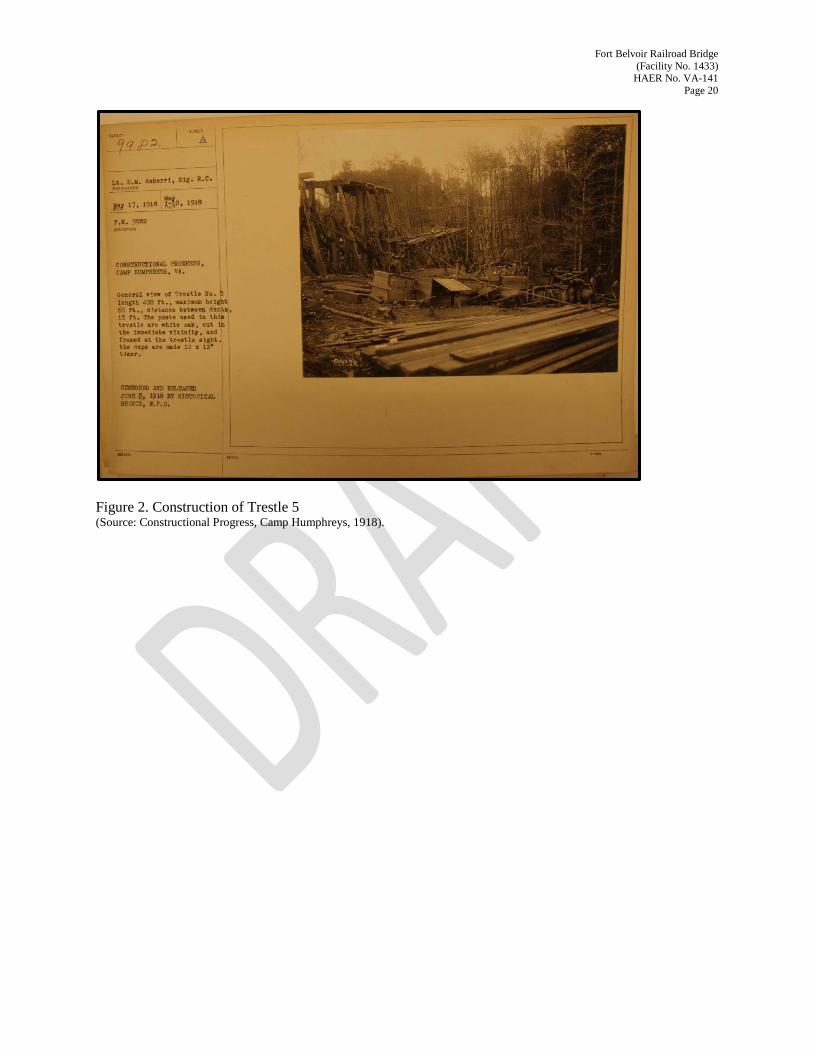
The original Trestle 5 extended 400’ and had a maximum height of 60’ (deBerri 1918). The distance between bents was 15’ (deBerri 1918). Trestle 5 was a multi-story structure completed of white oak hewn and cut at the trestle site or transported from other parts of the camp (deBerri 1918) (Figure 2). Work on the trestle was completed simultaneously from the north and south approaches; steam hoisting engines raised “the members from the ground to story after story, thus permitting all dowell (sic.) pins to be placed entirely through the cap and entirely into both the batter and plumb post sufficiently to give excellent bonding” (Park 1918:7 Appendix XXIII (f)).
By the late 1920s, it became apparent that replacement of trestles 2, 5, and 6 were necessary because they “were of war time construction made of green timbers, all of which was badly deteriorated and unsafe” (U.S. Quartermaster General 1928:2). In 1927, drawings prepared by the Quartermaster Corps depict a reinforced-concrete bridge with four arches, measuring 13’ across, on the south approach and three arches, also measuring 13’, on the north.
Replacement of the wood trestle with a reinforced-concrete arch bridge offered a potential costs savings. Among the primary advantages of concrete construction were its durability and relatively low maintenance costs (Miller et al. 2000:16). Use of concrete as a construction material for arch bridges was well established. First used in the United States in 1889 at the Golden Gate Park in San Francisco, California, reinforced-concrete arch bridges gained in popularity throughout the late nineteenth century and into the early twentieth century (Miller et al. 2000:16). Although less common than truss, beam, and slab bridges, concrete arch bridges in Virginia were not uncommon (Miller et al. 2000:24). Reinforced-

Fort Belvoir Railroad Bridge (Facility No. 1433)
HAER No. VA-141 Page 14
concrete arch bridges appeared in Virginia by 1904 (Miller et al. 2000:22). By the mid-twentieth century, such bridges had become the dominate bridge type (Miller et al. 2000:23). Concrete arch bridges often incorporated decorative railings or parapets, a feature absent in concrete arch railroad bridges.
The Quartermaster Corps jointly supervised the construction of a portion of U.S. Route 1, referred to as the Alexandria-Humphreys Road in contemporary accounts, under the Office of Public Roads and the Construction Division. The eight and a-half-mile road cost $346,542.79 (U.S. House of Representatives 1920:281). The Motor Transport Corps supplied road materials for four miles of the road; the remainder was provided by private contractor (U.S. House of Representatives 1920:281). Archival research suggests U.S. Route 1 south of the Fort Belvoir main entrance may not have been paved. Newspaper accounts from the 1920s describe major improvements along the entire length of the road leading from Richmond to Washington, D.C. (U.S. Route 1). The Richmond-Washington Highway, as the road was named in contemporary newspaper articles, was scheduled to open in spring 1927, after being under construction for several years (“Invite Nations to Celebration” 1927:1). It is possible that the plate girder referenced in the 1927 drawings was installed as part of the road improvement project.
The plans prepared for Facility No. 1433 are similar, in terms of the use of concrete, to those prepared for the replacement of Trestle 4 with a new bridge (Facility No. 2298), but are unique in design. The drawings for Facility No. 2298 incorporate some similarities in terms of design (i.e., arches) but otherwise it does not appear as if they were designed as part of an attempt to create a uniformed look or design aesthetic for the installation’s railroad crossings.
A girder connects the north and south approaches; the design of the girder is not depicted on the 1927 drawings. A new poured-concrete culvert to be located under the south span also is depicted on the drawings. The 1927 drawings indicate that concrete posts located at the north and south ends of the girder and the girder itself were present at the time the drawings were prepared in 1927. The drawings suggest that the wood trestle would remain in place during the construction of the replacement bridge. Significant fill would be required to accommodate major changes in grade (Figure 3). A photograph taken shortly after construction depicts the completed bridge (Figure 4).
The title block on the plans developed by the Quartermaster General does not suggest the design was based on standardized plans. Indeed, it appears that the drawing is unique and the new bridge design was adapted to incorporate the existing metal girder. Archival research did not identify photographs of masonry repair, or records or drawings that illustrate changes to the wood trestle over time. Field photographs taken during and shortly after construction of Trestle 5 do not depict the use of concrete. In addition, contemporary accounts do not reference the use of concrete in the construction of any of the wood trestles. The presence of the plate girder at the time the trestle was replaced suggests that repairs had occurred between the time the trestle was constructed in 1918 and replaced in 1928.
Five of the original wood-frame trestles were replaced in 1928 under two separate contracts. The Quartermaster General’s construction completion reports for filling the trestles summarize project details. The replacement of trestles 2, 5, and 6 were completed under contract W 406 - qm-2 by L. Morgan Johnston of Alexandria, Virginia, and trestles 3 and 4 were completed under contract No. W 406 - qm 55 by Jarboe & Houghton, Mechanicsville, Maryland, for a cost of $37,218.60 (U.S. Quartermaster General

Fort Belvoir Railroad Bridge (Facility No. 1433)
HAER No. VA-141 Page 15
1928:53). These two construction projects resulted in the removal of all six wood trestles. The crossings were infilled, or new culverts or bridges (Facility No. 1433 and Facility No. 2298) were constructed.
The Quartermaster supervised construction with the assistance of one Assistant Quartermaster and one inspector (U.S. Quartermaster General 1928:2). Public law 630 authorized the construction project. The work was awarded to L. Morgan Johnston for $51,281.46. The total cost of the work was $50,168.43 with $1,831.57 retained for other repairs to the track (U.S. Quartermaster General 1928:2). The replacement of Trestle 5 with Facility No. 1433 was completed in February 1928.
L. Morgan Johnston was a developer and rental property owner. As a general contractor, he completed projects for the public-sector. Some of his contracts included roadwork for the Department of the Navy and roadwork for local and state governments. As a developer and owner, he developed 30 hollow-tile, single-family dwellings in the Rucker-Johnston subdivision of Alexandria’s Rosemont neighborhood between 1919 and 1920 (Maxwell and Massey 1991:Section 8, page 51; The Washington Post 1919:15; The Washington Post 1920:5). He also acquired the Hermitage apartment building on Vermont Avenue in Washington, D.C. (The Washington Post 1921:1).
L. M. Johnston constructed culverts on Evarts Street in Washington, D.C. (“District of Columbia” 1916:46). The 1919 Annual Report of the Quartermaster General identified all contractors and subcontractors contracted for projects under the supervision of the construction division of the Army (U.S. House of Representatives 1920:389). L. M. Johnston was awarded a contract for road repair at Fort Myer, Virginia (U.S. House of Representatives 1920:374). The U.S. Department of the Navy entered into a contract with L. Morgan Johnston to construct roads at the Navy Mine Depot, Yorktown, Virginia, in 1927 (McCarl 1929:59). In legal documents filed by the Department of the Navy, L. Morgan Johnston was adjudged bankrupt in March 1928 (McCarl 1929:63).
The 1920 census records Lewis M. Johnston, aged 40, living on Columbia Pike in the Jefferson District of Alexandria, with his wife Daisy (age 39), his sons Sidney B. (age 17) and Lewis M. Johnston, Jr. (age 10) and his daughter Dorothy (age 15) (U.S. Census 1920). His occupation was identified as general contractor. The 1930 census records identify L. Morgan Johnston living on Columbia Pike in Jefferson District with his wife Daisy, his sons Sidney and L. Morgan Johnston, Jr., his daughter Dorothy, and his son-in-law James H. McCallister. His occupation was identified as general contractor (U.S. Census 1930). Census records suggest Lewis Morgan Johnston died by 1940. His wife Daisy, his daughter Dorothy, and his son-in-law James McCallister were recorded on North Chesterbrook Road in Arlington, Virginia (U.S. Census 1940).
Visual observation and archival research suggest the metal plate girder currently spanning U.S. Route 1 is not the same feature depicted on the 1927 drawing and the 1928 picture of the bridge. The manufacturer’s badge located on the northwest approach indicates the existing girder was installed in 1935 by the Virginia Bridge and Iron Company. One arch from each the north and south abutments were removed to accommodate the longer girder. The real property card for Facility No. 1433 indicates that the length of the girder in 1941 / 1942 was 100’, the same distance as the extant girder (Fort Belvoir Directorate of Public Works n.d.).

Fort Belvoir Railroad Bridge (Facility No. 1433)
HAER No. VA-141 Page 16
The Virginia Bridge and Iron Company was established in 1888 as the American Bridge Works (Carver 2008:215). After undergoing reorganization, the company was renamed the Virginia Bridge and Iron Company in 1895 (Carver 2008:215). The Roanoke, Virginia-based company expanded and by the early twentieth century, it maintained an annual capacity of 12,000 tons of manufactured products, making the company’s capacity the largest of any bridge manufacturer in the South (Carver 2008:215). The company continued to expand throughout the early twentieth century, eventually expanding operations to Charlotte, North Carolina; Atlanta, Georgia; and Memphis, Tennessee; New York, New York; and Los Angeles, California. The company produced steel rail cars and tanks, steel power houses, and steel stadiums in addition to bridge components (Carver 2008:216).
By the early 1930s, the company was the third largest steel fabricating company in the country (Carver 2008:216). A subsidiary of the U.S. Steel Corporation, the Tennessee Coal, Iron and Railroad Company of Birmingham, Alabama, acquired the Virginia Bridge and Iron Company in 1936 (Carver 2008:217). After its acquisition by the Tennessee Coal, Iron and Railroad Company, the company’s Roanoke operations were renamed the Virginia Bridge Company and survived through the Great Depression. The renamed Virginia Bridge Company manufactured products for the war effort including ships and landing barges, dry docks, and portable military bridges (Carver 2008:217). The company later was acquired by the American Steel Company and continued to produce steel for a variety of building projects (Carver 2008:217). Labor disputes contributed to the company’s closing during the mid-twentieth century (Carver 2008:217).
VIII. Resource Description
The Fort Belvoir Military Railroad Bridge is a reinforced-concrete and metal bridge whose current design represents a series of modifications from 1918 through 1935. Reinforced-concrete arches (two bays on the north elevation and three on the south) provide the approach to the single-span, deck plate girder that crosses over U.S. Route 1. The mowed rail corridor is flanked by woods; vegetation, consisting of vines, shrubs, and saplings, grow adjacent to and atop the abutments. A manufacturer’s badge reading “BUILT AT VIRGINIA BRIDGE & IRON CO. ROANOKE, VA. 1935” is located on the northwest approach span.
The north abutment measures 40’-8”, the south abutment measures 57’-8”, and the metal girder measures 100’ for a total span of 194’-9 ¼”. The bridge measures an average of 25’ in height, with the north abutment having a height of 24’ and the south abutment having a height of 25’-4”. Reinforced-concrete, free-standing, double-faced arches, resting on poured-concrete footers form the bridge abutments to create a structure similar to a viaduct. The rebar consists of “square-deformed bars” measuring 1”, ½”, and ¼”. The elevation design and visual connection is from the U.S. Route 1 approach. Each arch has a radius of 6’-6” with a distance of 13’ between piers. The arches are connected by interior, horizontal concrete bracing. A poured-concrete retaining wall obscures the northeast elevation of the north abutment. The minimal ornamentation is limited to the simple cornice, which is carried from the abutment through the girder.
Rocker bearings pinned to masonry posts terminating in modest capitals attach to the plate girder. The rocker bearings allow for the girder to move by absorbing load stresses. The bearings on the south approach are different from those located on the north approach. The bearings at the north approach are

Fort Belvoir Railroad Bridge (Facility No. 1433)
HAER No. VA-141 Page 17
fixed in the assembly, while those on the south approach allow for lateral movement. The tracks approaching the bridge no longer are extant; however, the rails, ties, and guard timbers remain on the plate girder. Boards were placed perpendicular to the ties on the girder deck. Riveted metal trusses support the underside of the girder, which is comprised of riveted panels, or web. Metal pipes attached to the plate girder carry utilities.
A review of archival photographs, visual observation, and verification of field measurements suggests that one arch from each the north and south abutments were removed when the existing plate girder was installed in 1935. The installation of the new plate girder resulted in the reduction of the south abutment to three arches and the north abutment to two arches. In 1973, the guard timbers, decking, and bridge ties were replaced with new materials (Fort Belvoir Directorate of Facilities Engineering var.).

Fort Belvoir Railroad Bridge (Facility No. 1433)
HAER No. VA-141 Page 18
Table 1. Railroad Equipment Required to Move Various Organizations of the Army at War Strength (Source: U.S. House of Representatives 1916:282).

Fort Belvoir Railroad Bridge (Facility No. 1433)
HAER No. VA-141 Page 19
Figure 1. Standardized Design for Trestle Construction (Source: War Department 1919:Plate 22).
Fort Belvoir Railroad Bridge (Facility No. 1433)
HAER No. VA-141 Page 20
Figure 2. Construction of Trestle 5 (Source: Constructional Progress, Camp Humphreys, 1918).

Fort Belvoir Railroad Bridge (Facility No. 1433)
HAER No. VA-141 Page 21
Figure 3. Facility 1433, Drawings Prepared by the Quartermaster General (Source: Fort Belvoir Directorate of Facilities Engineering).

Fort Belvoir Railroad Bridge (Facility No. 1433)
HAER No. VA-141 Page 22
Figure 4. Photograph of Facility No. 1433 Shortly after Construction (Source: U.S. Quartermaster General Construction Completion Report, 1928).

Fort Belvoir Railroad Bridge (Facility No. 1433)
HAER No. VA-141 Page 23
Works Cited Alaska Railroad Corporation. Timber Trestle Bridges in Alaska Railroad History, Electronic
document, http://alaskarailroad.com/Portals/6/pdf/projects/Timber%20bridge%20history%20booklet.pdf, n.d.
American Railway Engineering Association, Manual of the American Railway Engineering Association.
Definitions, Specifications and Principles of Practice for Railway Engineering (Chicago: American Railway Engineering Association, 1921)
Behling, Burton N. “Railroads – Their Development, Problems, and Prospects,” in U.S. Transportation.
Resources, Performance and Problems. A collection of Papers Prepared for the Transportation Research Conference Convened by the National Academy of Sciences at Woods Hole, Massachusetts. August, 1960. Publication 841-S. (Washington, D.C.: National Academy of Sciences-National Research Council, 1961). Electronic document, http://books.google.com/books?id=xy8rAAAAYAAJ&pg=RA1-PA203&dq=mobilization+railroads+united+states+world+war+II&hl=en&sa=X&ei=zdlCUvzVC7LG4APTqYG4Dw&ved=0CDUQ6AEwADgK#v=onepage&q=mobilization%20railroads%20united%20states%20world%20war%20II&f=false.
Carver, Martha. Tennessee’s Survey Report for Historic Highway Bridges. Prepared for the Tennessee
Department of Transportation. Electronic document, http://www.tdot.state.tn.us/environment/historic/bridgebook.htm, 2008
Cralle, Maury S. “Letter to Mr. Daniel Seymour” available from the post historian, U.S. Army Garrison
Fort Belvoir, Virginia, 1995 deBerri, E.M. Constructional Progress, Camp Humphreys, VA. P.N. 9982. Record Group 111-SC.
Records of the Office of the Chief Signal Officer. Prints: Military History, 1860 – 1938. 9862 to 9999. Box 70. (College Park, Maryland: National Archives and Records Administration, 1918)
“District of Columbia,” Engineering and Contracting, Volume XLVI, July 5. No. 1; p. 46, 1916 Fields, Deborah. “Post’s Railroad Status under Review,” Castle, vol. 56, no. 8; pp. 1, 1990 Fine, Lenore and Jesse A. Remington, United States Army in World War II. The Technical Services. The
Corps of Engineers: Construction in the United States (Washington, DC: Center of Military History, 1989)
Fort Belvoir Directorate of Facilities Engineering. Drawings from drawings vault. (U.S. Army Garrison
Fort Belvoir, Virginia: Directorate of Public Works, var.) Fort Belvoir Directorate of Public Works. “Fort Belvoir. Host to History. Second Edition.” (U.S. Army
Garrison Fort Belvoir, Virginia: Cultural Resources Manager, Directorate of Public Works, 2010) Real property card. (U.S. Army Garrison Fort Belvoir, Virginia: Cultural Resources Manager,
Directorate of Public Works, n.d.)

Fort Belvoir Railroad Bridge (Facility No. 1433)
HAER No. VA-141 Page 24
“Fort Humphreys, Virginia,” Undated manuscript. (U.S. Army Garrison Fort Belvoir, Virginia: available from the post historian: ca. 1930)
Gallager, Ray. “Fort Belvoir Railroad is 65 Years Old,” Castle; pp. 23, 1982 Grandine, Katherine and Deborah Cannan. Support and Utility Structures and Facilities (1917 – 1946).
Overview, Inventory, and Treatment Plan. Final Report. Prepared by R. Christopher Goodwin & Associates, Inc., Frederick, Maryland. Unpublished manuscript. Prepared for the Department of the Navy Atlantic Division, Naval Facilities Engineering Command, Norfolk, Virginia, 1995
Gray, Walter A., Major. History of Railroads at Fort Belvoir, Virginia (U.S. Army Garrison Fort Belvoir,
Virginia: post historian, 1949 “Invite Nations to Celebration,” Richmond Times-Dispatch. March 31, 1927 Hool, George A., William Spaulding Kinne, Roy Richard Zipprodt, Datzell Melvin Griffith. Steel and
Timber Structures (New York: McGraw-Hill Book Company, Inc. 1942) Hudson, Mary. “On Track: Post Train System. Trains Move Materials and Mobilize Belvoir,” Castle, 8
March, pp. 8, 1985 Maxwell, Shirley and James C. Massey. Rosemont Historic District National Register of Historic Places
Nomination Form (1991) Miller, Ann B., Kenneth M. Clark, and Matthew C. Grimes. Final Report. A Survey of Masonry and
Concrete Arch Bridges in Virginia. Virginia Transportation Research Council in Cooperation with the U.S. Department of Transportation Federal Highway Administration, 2000. Electronic document, http://www.virginiadot.org/vtrc/main/online_reports/pdf/00-r11.pdf.
McCarl, J.R. Decision of the Comptroller General of the United States. Volume 8, July 1, 1928 to June
30, 1929. (Washington, D.C.: Government Printing Office, 1929) Park, Richard, Colonel
The Military Railroad (excerpt). (U.S. Army Garrison Fort Belvoir, Virginia: post historian, 1918)
Standard Railway School. (U.S. Army Garrison Fort Belvoir, Virginia: post historian, 1918, Appendix XXIII (f))
Peeler, Kirsten and Melissa Crosby. National Register Nomination for Fort Belvoir Historic District.
Submitted to the Directorate of Public Works, Cultural Resources, U.S. Army Garrison Fort Belvoir, Virginia (2010)
U.S. Army Corps of Engineers. Context Study of the United States Quartermaster General Standardized
Plans 1866 – 1942. Seattle District, Technical Center of Expertise for Preservation of Structures and Buildings. (Prepared for the U.S. Army Environmental Center, Environmental Compliance Division, 1997)

Fort Belvoir Railroad Bridge (Facility No. 1433)
HAER No. VA-141 Page 25
U.S. Army Corps of Engineers. 304th. The Official History of the Three Hundred and Fourth Engineer
Regiment. Seventy-Ninth Division, U.S.A. The Regiment. Under supervision of its Commanding Officer (1920). Electronic document, http://google.com/books?id=icIMAAAAYAAJ&printsec=frontcover&source=gbs_ge_summary_r&cad=0#v=onepage&q&f=false
U.S. Census www.ancestory.com, 1920 www.ancestory.com, 1930 www.ancestory.com, 1940 U.S. House of Representatives
To Increase the Efficiency of the Military Establishment of the United States. Hearings before the Committee on Military Affairs. House of Representatives. Sixty-fourth Congress. First Session on the Bill to Increase the Efficiency of the Military. January 6 to February 11, 1916 (in two volumes). Vol. 1. (Washington, D.C.: Government Printing Office, 1916)
Camp A. A. Humphreys, VA. Construction of Officers’ Quarters. Hearings before the Committee on Military Affairs. 66 Congress, First Session, July 15. (Washington, D.C.: Government Printing Office, 1919)
Annual Reports – Quartermaster Genera (Director of Purchase and Storage), Chief of Chemical Warfare Service, Direct of Tank Corps, Chief of Construction Division, Chief of Coast Artillery, Chief of Real Estate Service for the Fiscal Year Ended June 30, 1919. 66th Congress, 2d Session. House Documents, Vol. 17. (Washington, D.C.: Government Printing Office, 1920)
U.S. Quartermaster General. Completion Report. Fort Belvoir, Virginia. Vol. 2. Record Group 77 Office
of the Chief of Engineers. Construction Completion Reports 1917-1943. Box 30 Camp Beauregard – Vol. 5 through Fort Belvoir Vol. 2. (College Park, Maryland: National Archives and Records Administration, College Park, Maryland, 1928)
Virginia Department of Historic Resources. Virginia Cultural Resource System. Railroad Bridge (Facility
No. 1433). Database accessed 9 October 2013 (n.d.) War Department
Professional Papers of the Corps of Engineers of the United States. Engineer Field Manual. Document No. 355. Volume 29. Office of the Chief of Engineers. (Washington, D.C.: Government Printing Office, 1918)
Manual of the Construction Division of the Army. Section C. Engineer Division 1918. Revised June 1, 1919 (Washington, D.C.: Consolidated Supply Co., Printers, 1919)
The Washington Post
“Beautiful Homes Now Nearing Completion at North Rosemont, Alexandria, Va.,” advertisement, September 26; pp. 15, 1919
“North Rosemont, Alexandria, Va.”, advertisement. April 25; pp. 5, 1920 “Hotel and Three Apartments Sold,” Third part, June 26; pp. 1, 1921

Fort Belvoir Railroad Bridge (Facility No. 1433)
HAER No. VA-141 Page 26
Whelan, Deborah C.; Leo Hirrel; William T. Dod; J. Hampton Tucker; and Katherine Grandine. Historic Context for Department of Defense World War II Permanent Construction. Final Report. Prepared by R. Christopher Goodwin & Associates, Inc. for the U.S. Army Corps of Engineers, Baltimore District, Baltimore, Maryland (1997)
Woolpert, Real Property Master Plan. Fort Belvoir. Long-Range Component – 1993 (1993)


INDEX TO PHOTOGRAPHS
FORT BELVOIR RAILROAD BRIDGE (Facility No. 1433) HAER No. VA-141 Bridge Spanning U.S. 1 Fort Belvoir Fairfax County Virginia ROB TUCHER PHOTOGRAPHER 9/6/2013
1. VIEW OF BRIDGE IN CONTEXT. VIEW LOOKING EAST.
2. APPROACH TO BRIDGE ALONG RAILROAD BED FROM NORTHWEST. VIEW LOOKING SOUTHEAST.
3. APPROACH TO BRIDGE ALONG RAILROAD BED FROM
SOUTHEAST. VIEW LOOKING NORTHWEST.
4. VIEW ACROSS DECK. VIEW LOOKING SOUTHEAST.
5. VIEW ACROSS DECK. VIEW LOOKING NORTHWEST.
6. OBLIQUE VIEW OF NORTHEAST ELEVATION. VIEW LOOKING WEST.
7. OBLIQUE VIEW OF NORTHEAST ELEVATION. VIEW LOOKING
SOUTHWEST.
8. OBLIQUE VIEW OF SOUTHWEST ELEVATION. VIEW LOOKING NORTHEAST.
9. NORTHWEST APPROACH SPANS. VIEW LOOKING NORTHEAST.
10. SOUTHEAST WING WALL AND SOUTHEAST APPROACH SPANS.
VIEW LOOKING SOUTH.
11. NORTHWEST ABUTMENT. VIEW LOOKING WEST.
12. SOUTHEAST ABUTMENT AND APPROACH SPANS. VIEW LOOKING EAST.
13. NORTHWEST PIERS. VIEW LOOKING SOUTH.

14. UNDERSIDE, SHOWING PLATE GIRDER FOOR SYSTEM. VIEW LOOKING NORTHWEST.
15. DETAIL VIEW WITHIN PLATE GIRDERS, SHOWING LATERAL
BRACING. VIEW LOOKING NORTHWEST.
16. DETAIL OF BRIDGE BEARING. VIEW LOOKING NORTH.

1
2

3
4

5
6

7
8

9
10

11
12

13
14

15
16