Embed Size (px)
Citation preview

Wireless Netw (2008) 14: 71–85
DOI 10.1007/s11276-006-7818-1
HISNs: Distributed gateways for application-level integrationof heterogeneous wireless networks∗
Phone Lin · Huan-Ming Chang · Yuguang Fang ·Shin-Ming Cheng
Published online: 9 June 2006C© Springer Science + Business Media, LLC 2006
Abstract Integration of different kinds of wireless networks
to provide people seamless and continuous network access
services is a major issue in the B3G network. In this paper,
we propose and implement a novel Heterogeneous network
∗This paper is an extension of the work that won the championship ofthe Mobile Hero contest sponsored by Industrial Development Bureauof Ministry of Economic Affairs, Taiwan, R.O.C., and was awardedUSD 30,000. The work of Lin, Chang and Cheng was supported inpart by the National Science Council (NSC), R.O.C, under thecontract number NSC94-2213-E-002-083 andNSC94-2213-E-002-090, and NSC 94-2627-E-002-001, Ministry ofEconomic Affairs (MOEA), R.O.C., under contract number93-EC-17-A-05-S1-0017, the Computer and CommunicationsResearches Labs/Industrial Technology Research Institute(CCL/ITRL), Chunghwa Telecom Labs, Telcordia Applied ResearchCenter, Taiwan Network Information Center (TWNIC), and MicrosoftCorporation, Taiwan. The work of Fang was supported in part by theUS National Science Foundation Faculty Early Career DevelopmentAward under grant ANI-0093241 and US National ScienceFoundation under grant DBI-0529012.
P. LinP. Lin, Department of Computer Science & InformationEngineering and Graduate Institute of Networking andMultimedia, National Taiwan University, Taipei 106, R.O.C.e-mail: [email protected]
H.-M. ChangDepartment of Computer Science & Information Engineering,National Taiwan University, R.O.C.e-mail: [email protected]
Y. Fang ( )Department of Electrical & Computer Engineering, University ofFlorida, USAe-mail: [email protected]
S.-M. ChengDepartment of Computer Science & Information Engineering,National Taiwan University, R.O.C.e-mail: [email protected]
Integration Support Node design (HISN) and a distributed
HISN network architecture for the integration of heteroge-
neous networks, under which the Session Mobility, Personal
Mobility, and Terminal Mobility for mobile users can be
maintained through the Session Management mechanism.
Thus, the HISN node can serve as an agent for the user to
access Internet services independent of underlying commu-
nication infrastructure. Our design is transparent to the bearer
networks and the deployment of the HISN network does not
need to involve the operators of the heterogeneous wireless
networks.
Keywords Heterogeneous networks . Heterogeneous
network integration support node (HISN) . Personal
mobility . Service mobility . Session mobility.
1. Introduction
In recent years, technologies for wireless networks such as
the terrestrial cellular systems, wireless local area networks
(WLANs), and wireless personal area networks (WPANs)
have been evolved quickly. The huge evolution, together with
the advances in computing capability of mobile devices, en-
able us to use various kinds of devices to access Internet
services. Integration of different kinds of wireless networks
(also known as heterogeneous networks) to provide us seam-
less and continuous network access services becomes a major
issue in the B3G or 4G networks.
Several studies [4,13,14] have been conducted to address
the issues for the integration of heterogeneous networks.
First, protocol and message format conversion for differ-
ent network protocols and device capabilities should be de-
signed. Second, while users roam among different networks,
the network should maintain the continuity for the active
Springer

72 Wireless Netw (2008) 14: 71–85
sessions, which is known as the “Session Mobility”. Third,
“Personal Mobility” to users residing in different kinds of
networks should meet two requirements:
Requirement 1. Reachability, that is, the user data can be
routed to the mobile device the user currently uses.
Requirement 2. Personalization, i.e., a personalized oper-
ating environment (e.g., storage space or preference
setups for users’ applications) can be provided by the
networks.
Fourth, the existing network protocols should not be noti-
fied with the new infrastructures introduced to integrate the
heterogeneous networks. Moreover, due to the exposure of
communication media and information exchanges, security
issue should be considered. Besides the above issues, the so
called “Terminal Mobility” should also be addressed, which
is defined as that within the coverage area of a network, the
network is able to track the locations of users’ terminals, and
seamlessly provide transmission services for the users. For
the Terminal Mobility management, protocols exist for most
of current wireless networks. Examples are GPRS Mobility
Management [9], Mobile IP [6], or Session Initiation Proto-
col [7]. To provide the terminal mobility in the heterogeneous
networks, we may reuse the existing terminal mobility mech-
anisms run in the different wireless networks.
The previous studies [4,13–15] have developed platforms
for the integration of heterogeneous wireless networks. The
Mobile People Architecture (MPA) project [14,15] aimed to
achieve the Reachability requirement of Personal Mobility,
which is a logical extension of the current networking model
and targets to place the users, rather than the devices, at the
endpoints of a communication session. A new layer, called
personal layer, is introduced on top of the application layer.
This layer focuses on personal-level routing, which allows
messages to be routed to users’ current network and device
with content conversion. The MPA uses the globally unique
Personal Online ID to identify a user, and utilizes the personal
proxy located at the user’s home network for location track-
ing. The personal proxy will receive communication services
on behalf of the user and forward it to the user. This can hide
the user’s real location, achieving location privacy. The per-
sonal proxy provides the necessary communication services
such as email, telephones, and ICQ messages, and being in-
dependent of networks makes the personal proxy easy to
extend. Through the introduction of person-routing in MPA,
the MPA lacks, however, the personal operating environment,
which is also an important part of personal mobility.
The ICEBERG project [12,13] at U.C. Berkeley integrates
the cellular telephony networks with Internet to provide the
Reachability requirement of Personal Mobility. The same as
MPA, the ICEBERG treats a user as a communication end-
point regardless of the device he/she uses. It is based on
Nina clustering computing platform [21], which takes care
of call setup and control, location tracking, and mapping
user names in heterogeneous networks into ICEBERG nam-
ing. The ICEBERG network is an overlay network of iPOPs
on top of the Internet. However, the use of ICEBERG ac-
cess point (which are bridges between various networks and
ICEBERG) needs modification of existing network compo-
nents, such as switches or bases stations in Public Switched
Telephone Network (PSTN), which is a difficult task for prac-
tical deployment. Besides, the ICEBERG emphasizes more
on reachability rather than personal operating environment.
The IPMoA [4] is a mobile-agent-based personal mobility
framework that utilizes mobile agents to support two require-
ments of personal mobility. There are three kinds of agents,
including Personal Application Assistant (PAA), Personal
File Assistant (PFA), and Personal Communication Assis-
tant (PCA). The PAA invokes applications and routes pro-
gram data for users. The PFA provides the access to user’s
personal files and maintains the synchronization for the files
in the different IPMoAs. The PCA handles the call establish-
ment and content conversion. When the user is located on
a visiting network of IPMoA, the PAA invokes the remote
methods to remotely execute applications in home network.
In these previous works, the Session Mobility issue was
not addressed. Most works adopted a centralized node ar-
chitecture to provide Personal Mobility for mobile users, in
which The centralized node may become a bottleneck. Be-
sides, most of them do not follow the standard to come out
with the security functionality, which significantly decreases
the integrity with Internet.
Besides the above previous studies, the 3GPP work-
ing group proposes the Virtual Home Environment concept
(VHE) [2] to provide seamless personal mobility services,
including personalized services and personal operating en-
vironment, on the Universal Mobile Telecommunications
System (UMTS) for end users. However, the VHE approach
limits only on UMTS networks and devices, which may not
be applicable to other kinds of heterogeneous networks.
The Wireless Application Protocol (WAP) forum proposes
the WAP gateway [25] to connect the mobile cellular network
with the Internet, which adopts the proxy approach. The WAP
gateway targets on the translation between the WAP and the
HTTP protocols, which does not maintain the personal or
session mobility for the users.
In this paper, we propose the design of a Heterogeneousnetwork Integration Support Node (HISN) for the integra-
tion of heterogeneous wireless networks. Then, we study a
distributed HISN network architecture under which seam-
less integration of heterogeneous networks is made possible.
Under this architecture, the HISN network maintains the Ses-
sion Mobility, Personal Mobility, and Terminal Mobility for
mobile users through the Session Management mechanism
while an HISN serves as an intelligent agent for mobile users
in Internet. Through the HISN network, the mobile users
Springer

Wireless Netw (2008) 14: 71–85 73
Fig. 1 The distributed HISN network architecture
can use different kinds of mobile devices to access Internet
service. To address the security over HISN network, we de-
ploy a standard security protocol “PKI” [5] for the secure
communication between two HISNs.
The rest of this paper is organized as follows. Section 2
illustrates the distributed HISN network architecture.
Section 3 describes the implementation of the HISN.
Section 4 details the procedures for the Session Manage-
ment mechanism in this network. Section 5 evaluates the
performance of the HISN network. We conculde this paper
in Section 6.
2. The HISN network architecture
This section discusses the HISN network architecture.
As shown in Fig. 1, there are three kinds of nodes in the
HISN network: HISN nodes (Figs. 1 (1) and (2)), Home
Database with Certification Authority (Fig. 1 (3)), and Intel-
ligent Browsers (IBs; Figs. 1 (4) and (5)). The HISN node
is a gateway for users, through which users may use differ-
ent kinds of devices through different kinds of networks to
access Internet application servers (Fig. 1 (6)).
In the HISN network, the user may connect to the HISN
node through two kinds of connection media: the public-
domain media (e.g., GPRS or UMTS) and the private-domain
media (e.g., WLAN, IrDA, and Bluetooth). For an HISN
node, there may be more than one public-domain media or
private-domain media connected. The user may roam be-
tween the service areas of different HISNs. To make the user
gain seamless service between an old node and a new HISN
node, the Session Management mechanism is deployed (to
be elaborated later) in the HISN node. The functionalities of
each node in the HISN network are described as follows.
HISN Node: See Figs. 1 (1) and (2). The HISN node is the
primary serving node in the HISN network. In a HISN
node, we implement the Session Management mech-
anism to support personal mobility, session mobility,
UserID Passw ord Serv ingHIS N
User A abcd IP of HISN B
User B 1234 --
User C wxyz IP of HISN X
Fig. 2 Examples of entries in home database
and terminal mobility for mobile users. The security
mechanism is accommodated in the HISN architec-
ture to guarantee the secure access to the HISN net-
work. In an HISN node, the connection-media inter-
faces for heterogeneous networks (e.g., IrDA, WLAN,
Bluetooth, and GPRS) are provided to allow users to
use different mobile devices to access the HISN. We
implement a content format translation function to en-
capsulate the content obtained from Internet with the
format that can be displayed on the mobile terminal.
The protocols (e.g., Telnet, FTP, and E-Mail) of the In-
ternet applications are implemented in an HISN. The
details for the implementation of an HISN node will
be elaborated in Section 3.
Home Database with Certificate Authority: See Fig. 1
(3). This database maintains the service information
for the users. When a user subscribes to the HISN net-
work, a permanent entry is created for the user. The
entry consists of three fields: UserID (to store the ID1
of the user), Password (to store the password for autho-
rization of the user), and ServingHISN (to store the IP
address of the HISN where the user currently resides
at). Figure 2 shows examples of the entries in the Home
Database.
Following the PKI2 infrastructure [5], the Certificate
Authority in the Home Database node is responsible
for authenticating and publishing certificates to the
mobile devices and the HISN nodes involved. With
the certificates, the mobile devices and HISNs can be
verified for their validity, and the communication in-
formation (between a mobile device and an HISN or
between two HISNs) can be encrypted/decrypted by
the public and private secure key.
Intelligent Browser (IB): See Figs. 1 (4) and (5). An IB is
a software component installed in the user’s device to
communicate with an HISN node. We implement an
intelligent user interface on IBs.
Due to the page limitation, this paper omits the details of
the implementation for the Home Database with CA and the
1 The UserID is a unique ID in the HISN network for the mobile userto identify himself/herself.2 PKI is a system of public key encryption using digital certificatesfrom Certificate Authorities and other registration authorities that verifyand authenticate the validity of each party involved in an electronictransaction.
Springer

74 Wireless Netw (2008) 14: 71–85
IB. We focus on the implementation of an HISN node and
the Session Management mechanism.
3. The implementation of an HISN node
Figure 3 illustrates the software architecture of an HISN,
which consists of five components: Connection Media
Adapter, Content Format Adapter, Management Part, Per-
sonal Operating Environment, and Internet Service Module.
The details of these components are given below:
Connection Media Adapter: See Fig. 3 (1). This compo-
nent is responsible for sending/receiving the user data
to/from mobile devices transparently through hetero-
geneous networks. In a heterogeneous network, this
component acts as a terminal, and an HISN can be
addressed by the ID (e.g., IP address or phone num-
ber) used in the heterogeneous network. Thus, the de-
ployment of an HISN need not involve the operators
of individual networks. Currently, an HISN can con-
nect to five kinds of networks: Infrared [24], Blue-
tooth [23], Ethernet, WLAN [16], and GPRS [9]. The
data are delivered to these different network interfaces
directly through the comm port or TCP connection.
Following our design, an HISN node can be easily ex-
tended to connect to other kinds of networks as time
evolves.
HISN
Management Part
Connection
Media Adapter
Content
Format
Adapter
XML
WML
xHTML
SMS
SMIL
1 2
SMS, MMS
GPRS
WLAN
Bluetooth
Irfrared
Personal Operating Environment
Mobility Manager
Internet Service ModuleWeb
Browser
FTP
Telnet
MSN
File Manager
5
Ethernet
Security Manager
4
Internet Service
Heterogeneous N
etworks
3
TranslatorVisitor User
Database
Fig. 3 The software architecture of an HISN
Content Format Adapter: See Fig. 3 (2). This component
handles the content format translation. According to
the mobile device a user currently uses, this compo-
nent dynamically encapsulates the content (received
from the Internet or a mobile device) into the format
that can be interpreted by and shown on the mobile
device. We implement the Translator to convert the
content into different formats, where the eXtensible
Stylesheet Language (XSL) [17] is used to express
the translation rule. Currently, five content formats
are supported by an HISN: the eXtensible Markup
Language (XML) [1], the Wireless Markup Lan-
guage (WML) [25], the Extensible Hypertext Markup
Language (xHTML) [8], the Short Message Service
(SMS) [18], and the Synchronized Multimedia Inte-
gration Language (SMIL) [10]. Figure 4 demonstrates
how the Translator translates an XML message to a
WML message. The content between the 〈xsl:template
match=“/APList”〉 and 〈/xsl:template〉 tags (Figs. 4
(b.1) and (b.5)) describes the translation rule for the
block of data between the 〈APList〉 and 〈/APList〉tags (Figs. 4 (a.1) and (a.3)). The content between the
〈xsl:for-each select=“Data”〉 and 〈/xsl:for-each〉 tags
(Figs. 4 (b.3.1) and (b.3.5)) describes the translation
rule between the 〈Data〉 and 〈/Data〉 tags (Fig. 4 (a.2)).
According to the script defined in Figs. 4 (b.3.2)–
(b.3.4), the content between two 〈Data〉 tags is removed
and encapsulated into a WML message format (c.2),
and the (b.2) and (b.4) blocks are added to the head,
(c.2), and the end, (c.3), respectively.
Management Part: See Fig. 3 (3). This part consists of
two managers: the Security Manager and the Mobility
Manager. The Mobility Manager (Fig. 3 (3.1)) routes
the messages and data between a mobile device and an
Internet Service Module (to be elaborated later; Fig.
3 (5)). When the mobile user roams among different
HISNs, he/she may activate different applications on
the different HISNs. Suppose that the user currently
resides in HISN A and activates an application. The
Mobility Manager in HISN A stores the application
information, the IP address of HISN A, in the Visitor
Fig. 4 An example for thetranslation from the contents inXML format into that in WMLformat
Springer

Wireless Netw (2008) 14: 71–85 75
User Database in the Personal Operating Environment
(to be elaborated later; Fig. 3 (4)). The Mobility Man-
ager also stores the user-related information (includ-
ing the address of the mobile device, e.g., IP address or
MSISDN, and the IP address of HISN A) in the Visitor
User Database. This information is referenced for rout-
ing. The Mobility Manager accommodates the Session
Management mechanism to correctly route the user
data. The details of the Session Management mech-
anism is described in the next section. The Security
Manager (Fig. 3 (3.2)) is responsible for authentication
of communication entities, authorization of the legal
usage of resource, and security of the user data. The
implementation of the Security Manager follows the
Public Key Infrastructure (PKI) standard, X.509 [5].
Personal Operating Environment: See Fig. 3 (4). This
component maintains the user-related information.
There is a Visitor User Database in the Personal Op-
erating Environment, which maintains the mobile user
information. When a mobile user accesses an HISN
node, a UserProfile context is created in the Visitor
User Database for the user. As shown in Table 1,
a UserProfile context consists of five fields: UserID,
CurrentHISN, DeviceProfile, NetworkProfile, and UserState.
The UserID stores the User ID. The CurrentHISN field
stores the IP address of the HISN which the user
currently accesses. The DeviceProfile field stores the
related-information (i.e., device type; e.g., PDA or
notebook) of the mobile device the user currently uses.
The NetworkProfile field keeps the related-information
(i.e., the network type and the MSISDN or IP ad-
dress of the mobile device) for the network (the user
currently accesses). The UserState maintains the sta-
tus for the HISN network access of the user, which
consists of five states: IDLE, LOGIN, RESUMING,
ACTIVE, or STANDBY. A corresponding state ma-
chine (to be elaborated later) is run for the transitions
of the five states.
When a mobile user activates a session through an
HISN node to the Internet, a Session context is created
to maintain the status of the session, which is contained
in the user’s UserProfile context. Each UserProfile
context may contain zero or more Session contexts.
As shown in Table 1, a Session context consists of
seven fields: SessionID, LocatedHISN, ApplicationName,
SessionState, TunnelID, SecretKey, and BufferedData. The
SessionID field stores the ID of the session, which is
used as the reference key for searching the Session
context. The LocatedHISN field stores the IP address
of the HISN where the user creates the session. The
ApplicationName field stores the types (e.g., Telnet
or Email) of the application for the session. The
SessionState field maintains the status of a session:
ACTIVE, SUSPEND, and MIGRATE. We main-
tains a state machine for the transitions of the three
states, which will be described later. The TunnelID
stores the ID of the tunnel serving the session. The
SecretKey field stores a symmetric ciphering key
to encrypt/decrypt the transmitted user data. The
BufferedData stores the file pointer to the file used to
buffer the user data of a session.
Internet Service Module: See Fig. 3 (5). This part imple-
ments the classes of the agents for users to access
Internet applications, e.g., FTP and Telnet. Currently,
we implement six kinds of agents, Web Browser,
FTP, MSN, Email, Telnet, and File Manager.
Our implementation can be easily extended to accom-
modate more application agents. The Web Browseragent runs the HTTP protocol to retrieve the web
information in the Internet. The FTP clientagent provides functions for downloading/uploading
files from/to an Internet host. The MSN,Email, and
Table 1 HISN UserProfile andsession contexts Field Description
UserID: The primary reference key to search the UserProfile context.
CurrentHISN: The IP address of the HISN the user currently accesses.
DeviceProfile: Related-information of the device the user currently uses.
NetworkProfile: Related-information of the network through which the user accesses the HISN.
UserState: User state: IDLE, LOGIN, RESUMING, ACTIVE, or STANDBY.
Each UserProfile context may contain zero or more of the following Session contexts:
SessionID: The identity of the application session.
LocatedHISN: The IP address of the HISN where the session is created.
ApplicationName: The application type of the session.
SessionState: Session state: ACTIVE, SUSPEND, or MIGRATE.
TunnelID: The identity of the tunnel through which the user data is delivered.
SecretKey: The ciphering key of the secured tunnel.
BufferedData: The file pointer to the file used to buffer the user data.
Springer

76 Wireless Netw (2008) 14: 71–85
Telnet agents serve as the clients for the instant mes-
saging, telnet, and Email applications, respectively.
TheFile Manager agent is a client software imple-
menting functions to access the Internet remote user
file storage, where the Network File System (NFS),
Server Message Block (SMB), and Common Internet
FileSystem (CIFS) protocols are implemented.
4. The session management mechanism
This section describes the Session Management mechanism
in the HISN network, which consists of seven procedures: the
Login procedure, the Application Activation procedure, the
Application Termination procedure, the Logout procedure,
the Suspend procedure, the Resume procedure, and the Tun-
neling procedure. Before the user gains the service of a HISN
node, the Login procedure is executed between the mobile
device and an HISN node. After the execution of the Lo-
gin procedure, the user can activate the Internet application
through the HISN node by executing the Application Acti-
vation procedure. The user can turn off the running Internet
applications through the Application Termination procedure.
The Logout procedure is exercised when the user quits the
service of the HISN node. During the execution of an appli-
cation, the mobile user may move out of the service area of an
HISN and move into the service area of another HISN node.
At this moment, the Suspend procedure is exercised between
the old HISN node and the mobile device, and the Resume
procedure is executed between the new HISN node and the
mobile device to continue the application session. Then, the
Tunneling procedure is run between the old HISN node and
the new HISN node for the packet forwarding from the old
HISN node to the new HISN node. The details of the seven
procedures are given in the following few subsections.
4.1. State machines for session management
The Session Management maintains a finite state machine Su
for the user behavior and a finite state machine Ss for session
status. The state diagrams for Su and Ss are shown in Figs. 5
and 6, respectively.
The Su is maintained in the UserState field of the User-
Profile context, and characterized by one of the five dif-
ferent states: IDLE, LOGIN, RESUMING, ACTIVE, and
STANDBY. At the IDLE state, the UserProfile context holds
invalid information for user’s location, device, and network.
The user is unreachable in this case. The Login procedure
and authentication are executed at the LOGIN state while the
UserProfile context is not valid. At the RESUMING state,
the Resume procedure is performed, where the Session con-
texts can be updated or resumed. At this time, the UserProfile
context is valid but the Session contexts (if any) are invalid. At
IDLE
LOGIN
ACTIVERESUMING
STANDBY
(a.1)
(a.2)
(a.3) (a.5)
(a.6)
(a.4)
(a.8)
(a.7)
Fig. 5 State diagram for state machine Su for user behavior
ACTIVE
MIGRATE
SUSPEND
(b.3) (b.4)
(b.1) (b.2)
Fig. 6 State diagram for statemachine Ss for session status
the ACTIVE state, the user may perform the Application Ac-
tivation and/or Termination procedures. The corresponding
Session contexts will be created or terminated. In this state,
the user is reachable by the HISN network and the UserPro-
file and Session contexts are valid. At the STANDBY state,
the Suspend procedure is performed, where the messages and
user data are buffered.
The Ss is maintained in the SessionState field of the Ses-
sionProfile context, and characterized by one of the three
different states: ACTIVE, SUSPEND, and MIGRATE. At
the ACTIVE state, the session is activated through the Appli-
cation Activation procedure. The application can deliver the
user data at this state. At the SUSPEND state, the activated
session is suspended and the HISN node will buffer mes-
sages and maintain the application session for the user. At
the MIGRATE state, the user performs the Resume proce-
dure among different HISN nodes, the TunnelID and SecretKey
fields are updated and the messages or user data are delivered
through the tunnel between two different HISN nodes.
The state transitions in the Su and Ss state machines are
described in the following subsections.
4.2. The login procedure
Suppose that a user previously accessed the HISN node Ho
through the access network No, and then he/she logins into
the HISN node Hn , where the access network is Nn . Figure 7
Springer
Wireless Netw (2008) 14: 71–85 77
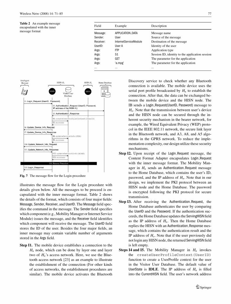
Table 2 An example messageencapsulated with the innermessage format
Field Example Description
Message: APPLICATION DATA Message name
Sender: User Source of the message
Receiver: InternetServiceModule Destination of the message
UserID: User A Identity of the user
Args: FTP Application type
Args: S1 Session ID, identity to the application session
Args: GET The parameter for the application
Args: ‘a.mpg’ The parameter for the application
... ... ...
Fig. 7 The message flow for the Login procedure
illustrates the message flow for the Login procedure with
details given below. All the messages to be proceed is en-
capsulated with the inner message format. Table 2 shows
the details of the format, which consists of four major fields:
Message, Sender, Receiver, and UserID. The Message field spec-
ifies the command in the message. The Sender field specifies
which component (e.g., Mobility Manager or Internet Service
Module) issues the message, and the Receiver field identifies
which component will receive the message. The UserID field
stores the ID of the user. Besides the four major fields, an
inner message may contain variable number of arguments
stored in the Args field.
Step I1. The mobile device establishes a connection to the
Hn node, which can be done by layer one and layer
two of Hn’s access network. Here, we use the Blue-
tooth access network [23] as an example to illustrate
the establishment of the connection (For other kinds
of access networks, the establishment procedures are
similar). The mobile device activates the Bluetooth
Discovery service to check whether any Bluetooth
connection is available. The mobile device uses the
serial port profile broadcasted by Hn to establish the
connection. After that, the data can be exchanged be-
tween the mobile device and the HISN node. The
IB sends a Login Request(UserID, Password) message to
Hn . Note that the transmission between user’s device
and the HISN node can be secured through the in-
herent security mechanism in the bearer network, for
example, the Wired Equivalent Privacy (WEP) proto-
col in the IEEE 802.11 network, the secure link layer
in the Bluetooth network, and A3, A8, and A5 algo-
rithms in the GPRS network. To reduce the imple-
mentation complexity, our design utilize these security
mechanisms.
Step I2. Upon receipt of the Login Request message, the
Content Format Adapter encapsulates Login Request
with the inner message format. The Mobility Man-
ager in Hn sends an Authentication Request message
to the Home Database, which contains the user’s ID,
password, and the IP address of Hn . Note that in our
design, we implement the PKI protocol between an
HISN node and the Home Database. The password
is encrypted following the PKI protocol for secure
transmission.
Step I3. After receiving the Authentication Request, the
Home Database authenticates the user by comparing
the UserID and the Password. If the authentication suc-
ceeds, the Home Database updates the ServingHISN field
as the IP address of Hn . Then the Home Database
replies the HISN with an Authentication Response mes-
sage, which contains the authentication result and the
IP address of Ho. Note that if the user previously did
not login any HISN node, the returned ServingHISN field
is left empty.
Steps I4 and I5. The Mobility Manager in Hn invokes
the createUserProfileContext(UserID)function to create a UserProfile context for the user
in the Visitor User Database. The default value of
UserState is IDLE. The IP address of Hn is filled
into the CurrentHISN field. The user’s network address
Springer
78 Wireless Netw (2008) 14: 71–85
obtained from the Connection Media Adapter is stored
in the NetworkProfile field. Then, the Mobility Manager
changes Su from IDLE to LOGIN (Transition a.1 in
Fig. 5). The Visitor User Database returns a successvalue to the Mobility Manager.
Step I6. The Mobility Manager in Hn sends IB a Up-
date Device Info Request message to request the con-
figuration information of the mobile device.
Step I7. The IB responds the Update Device Info Resonse
message to the Mobility Manager of Hn to update the
information about the type of the mobile device (e.g.,
PDA). The detection of the capability of the mobile
device (e.g., CPU speed, memory size, or screen size)
is done through the invocation of the standard API
provided by the OS of a mobile device [22].
Steps I8 and I9. The Mobility Manager invokes the
updateDeviceInfo() function to store the infor-
mation for the mobile device type to the DeviceProfile
field of user’s UserProfile context in the Visitor User
Database. The Visitor User Database returns thesuc-cess value to the Mobility Manager.
Steps I10 and I11. The Hn and the IB exchange the Up-
date Network Info Request and Update Network Info
Response message pair to update the information about
the access network, e.g., GPRS or WLAN.
Steps I12 and I13. The Mobility Manager of Hn invokes
theupdateNetworkInfo() function to update the
NetworkProfile field in the UserProfile context for the
user in the Visitor User Database. Then the Visitor User
Database returns a success value to the Mobility
Manager.
Step I14. The Hn triggers the Resume procedure to resume
the sessions that were created in the Ho node. The de-
tails of the Resume procedure will be elaborated later.
Step I15. The HISN Hn sends a Login Response message to
the IB to indicate the result of the Login procedure.
After successful login, the user may access the
Internet applications through the Hn node.
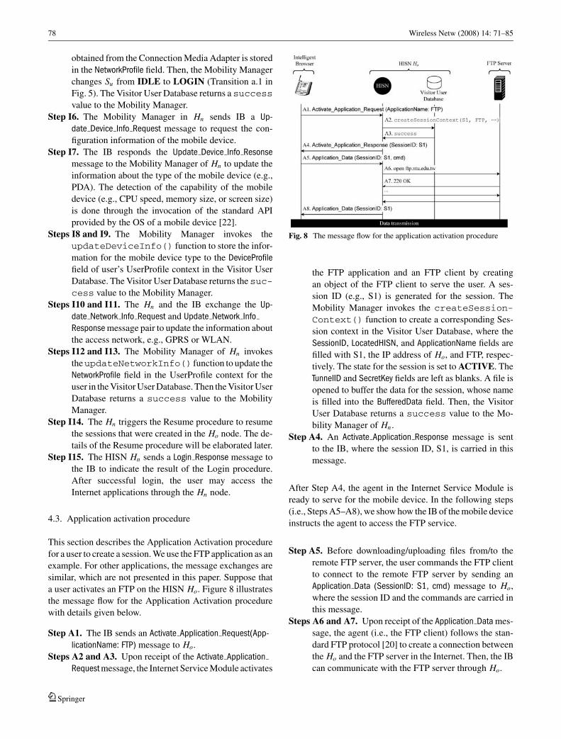
4.3. Application activation procedure
This section describes the Application Activation procedure
for a user to create a session. We use the FTP application as an
example. For other applications, the message exchanges are
similar, which are not presented in this paper. Suppose that
a user activates an FTP on the HISN Ho. Figure 8 illustrates
the message flow for the Application Activation procedure
with details given below.
Step A1. The IB sends an Activate Application Request(App-
licationName: FTP) message to Ho.
Steps A2 and A3. Upon receipt of the Activate Application
Request message, the Internet Service Module activates
Fig. 8 The message flow for the application activation procedure
the FTP application and an FTP client by creating
an object of the FTP client to serve the user. A ses-
sion ID (e.g., S1) is generated for the session. The
Mobility Manager invokes the createSession-Context() function to create a corresponding Ses-
sion context in the Visitor User Database, where the
SessionID, LocatedHISN, and ApplicationName fields are
filled with S1, the IP address of Ho, and FTP, respec-
tively. The state for the session is set to ACTIVE. The
TunnelID and SecretKey fields are left as blanks. A file is
opened to buffer the data for the session, whose name
is filled into the BufferedData field. Then, the Visitor
User Database returns a success value to the Mo-
bility Manager of Hn .
Step A4. An Activate Application Response message is sent
to the IB, where the session ID, S1, is carried in this
message.
After Step A4, the agent in the Internet Service Module is
ready to serve for the mobile device. In the following steps
(i.e., Steps A5–A8), we show how the IB of the mobile device
instructs the agent to access the FTP service.
Step A5. Before downloading/uploading files from/to the
remote FTP server, the user commands the FTP client
to connect to the remote FTP server by sending an
Application Data (SessionID: S1, cmd) message to Ho,
where the session ID and the commands are carried in
this message.
Steps A6 and A7. Upon receipt of the Application Data mes-
sage, the agent (i.e., the FTP client) follows the stan-
dard FTP protocol [20] to create a connection between
the Ho and the FTP server in the Internet. Then, the IB
can communicate with the FTP server through Ho.
Springer

Wireless Netw (2008) 14: 71–85 79
Step A8. The Ho sends the Application Data (SessionID: S1)
message to the IB, which contains the execution results
for the user.
4.4. Suspend and resume procedures
By performing the Suspend and Resume procedures, the user
can move out of the service area of an HISN and enter the ser-
vice area of another HISN without loss of an ongoing session.
The range of the service area of an HISN is determined
by the connection medium through which the user accesses
the HISN (i.e., the service area of the HISN is equal to the
radio coverage of the connection medium by which the user
accesses the HISN). For example, if the user uses the Blue-
tooth to access the HISN, the service area of the HISN is
equal to the radio coverage of the Bluetooth.
Assume that the user currently uses the device Do to con-
nect to the HISN Ho through the Network No, and later he/she
uses the device Dn to connect to the HISN Hn through the
Network Nn . Seven possible scenarios can be considered for
the user movement:
Case I: Inter-device movement. Do �= Dn , No = Nn , and
Ho = Hn . For example, the user may change the
mobile device for better mobility (e.g., from a
desktop to a PDA).
Case II: Inter-connection medium movement. Do = Dn ,
No �= Nn , and Ho = Hn . As mentioned previ-
ously, there are two kinds of connection media:
the public-domain media and the private-domain
media. The user may choose the private-domain
media instead of the public-domain media for the
economical concern, security reasons, connection
availability, and the capabilities of connection
media.
Case III: Inter-HISN movement. Do = Dn , No = Nn , and
Ho �= Hn . The user may roam from one HISN to
another due to the limited range of the HISN’s
service area or other considerations as mentioned
in Case II.
Case IV: Inter-device and connection medium movement.Do �= Dn , No �= Nn , and Ho = Hn . In this case,
the user changes the mobile device and the type
of the access network for the same HISN.
Case V: Inter-device and HISN movement. Do �= Dn ,
No = Nn , and Ho �= Hn . The user uses different
mobile devices among different HISNs, but does
not change the access network to the HISN.
Case VI: Inter-connection medium and HISN movement.Do = Dn , No �= Nn , and Ho �= Hn . The user
uses the same device to access different HISNs
through different access networks.
Fig. 9 The message flow for the suspend and resume procedures
Case VII: Inter-device, connection medium, and HISNmovement. Do �= Dn , No �= Nn , and Ho �= Hn .
When a user roams to a new HISN Hn , he/she
uses different device and different type of
network to access Hn .
The Suspend procedure is executed between the old HISN
Ho and the mobile device before the user moves out of the
service area of Ho. The HISN network suspends the activated
sessions and buffer the data for the sessions. When the user
logins into the new HISN node Hn , the Resume procedure is
executed to continue the suspended application.
In this subsection, we illustrate the Suspend and Resume
procedures by considering Case VII where Do �= Dn , No �=Nn , and Ho �= Hn . For other cases, the message flows for the
two procedures can be easily modified. As shown in Fig. 9
(a), suppose that the user suspends the application with the
session ID, S1, at the old HISN Ho, where the user uses the
mobile device, Do. Then the user logins into the new HISN
Hn by using a new mobile device, Dn .
Suspend Procedure:Step S1. The IB sends a Suspend Session Request(UserID)
message to Ho, where the user ID is carried in this
message.
Step S2. Upon receipt of Suspend Session Request, the Mo-
bility Manager of Ho changes the state of Ss from
ACTIVE to SUSPEND (Transition b.1 in Fig. 6), and
starts to buffer the data for the S1 session into the
file whose name is specified in the BufferedData field of
the Session context. The state of Su is changed from
ACTIVE to STANDBY (Transition a.5 in Fig. 5). Then,
Ho responds a Suspend Session Response message to Do,
and starts a timer, Ts . The Ho expects to receive an
Springer

80 Wireless Netw (2008) 14: 71–85
HISN Context Request message (to be elaborated later; see
Step R2) from other HISN node before the Ts timer
expires. When the Ts timer expires, the Suspend proce-
dure is exited.
After entering the service area of Hn , the user executes the
Login procedure by using the new mobile device Dn . During
the execution of the Login procedure, the Hn determines the
previous HISN (i.e., Ho) by querying the Home Database (see
Step I2.2). Then the Resume procedure is executed among
Dn , Hn , and Ho. Figure 9 (b) illustrates the message flow for
the Resume procedure with details given below.
Resume Procedure:Step R1. The Mobility Manager of Hn sends a
HISN Context Request(UserID) message with the user’s ID
to the Mobility Manager of Ho to request the Session
contexts of the user(if any). Note that the IP address of the
HISN Ho is obtained in Step I2.2 in the Login procedure.
Then, the Mobility Manager changes the state of Su from
LOGIN to RESUMING (Transition a.1 in Fig. 5).
Step R2. Upon receipt of HISN Context Request, the Mobility
Manager of Ho retrieves the Session context of the user
by querying the Visitor User Database where the user’s
ID is used as the reference key. The Mobility Manager of
Ho sends the
HISN Context Response message to the Mobility Manager
of Hn , which contains the Session contexts for the user
(i.e., Session context for S1).
Step R3. After receiving the HISN Context Response mes-
sage, Hn stores the received Session context into the user’s
UserProfile context in the Visitor User Database. Then the
Mobility Manager checks the LocateHISN fields in the Ses-
sion context to see whether any other HISN maintains
suspended sessions for the user. If so, the Hn executes the
Tunneling procedure to establish the tunnels between Hn
and the previous HISNs. Details of the Tunneling proce-
dure will be given in the next subsection.
Step R4. After Step R3, the tunnel between Hn and Ho has
been established. If the Ho has buffered data (for the ses-
sions that are created in Ho) to be delivered to Dn , Ho
sends one or more Update Application Data (SessionID: S1)
messages carrying the data to Dn through the tunnel.
Step R5. After receiving the buffered data, Dn sends a
Update Application Data Ack message to Ho through Hn
for acknowledgment. The Mobility Managers of Hn and
Ho change the states of their Ss state machines from
SUSPEND to MIGRATE (Transition b.3 in Fig. 6), indi-
cating that the data can be exchanged through the tunnel.
Note that if there are more than one session to be resumed,
Steps R4 and R5 are executed repeatedly until all the sessions
in the HISN Ho are resumed.
Steps R6 and R7. The Ho sends Hn a Resume Session
Complete message, which indicates that all the ses-
sions on Ho are resumed. Then Hn returns a Re-
sume Session Complete Ack message. The Mobility Man-
ager of Ho changes the state machine Su from STANDBYto ACTIVE (Transition a.6 in Fig. 5) for the user.
If there are other HISNs having activated sessions for the
user, Hn will take the same actions in Step R3 to create one
tunnel, dedicated for the user, for one HISN, and Steps R4-
R7 are executed repeatedly to resume the activated sessions
on Hn for the user.
Steps R8 and R9. The Hn and IB Dn exchange the
Resume Session Success and Resume Session Success
Ack messages pair. The Mobility Manager of Hn changes
the state of Su from RESUMING to ACTIVE (Transi-
tion a.4 in Fig. 5). For the data of the applications that are
created in Ho, they are delivered among Dn , Hn , Ho, and
the application servers.
4.5. Tunneling procedure
When a mobile user activates applications on different
HISNs, tunnels will be established between the HISNs for
routing data messages for the user. For each HISN-HISN
pair, one or more tunnels may exist. In our implementation,
we utilize the PKI protocol [5] and a secret key to secure the
tunnel. Figure 10 illustrates the message flow for the creation
of a tunnel.
Tunneling procedure:Step U1. The Hn sends a Create Tunnel Request(certificate,
UserID, TunnelID) message to Ho. The message carries the
certificate of the Hn , the user’s ID, and a randomly gen-
erated tunnel ID.
Step U2. Upon receipt of Create Tunnel Request, Ho con-
firms the identity and validity of Hn by checking the
certificate of Hn . If the certificate is valid, Ho generates
U1. Crea te_ Tunne l_Reque s t (certif icate , UserID,
Tun ne lID)
U2. Crea te_ Tunne l_Resp onse (en crypted secret key )
U3. Create_Tunne l_Ack
HISN Hn HISN Hn
HISN HISN
Fig. 10 The message flow for the tunneling procedure
Springer

Wireless Netw (2008) 14: 71–85 81
a secret key to secure the tunnel. The secret key is
transmitted as the user data, which is encrypted by the
public key of Hn in the certificate. Then, Ho sends a Cre-
ate Tunnel Response(encrypted secret key) message to Hn .
Step U3. Upon receipt of Create Tunnel Response message,
Hn decrypts the data by using its own private key, and
obtains the secret key. Then Hn sends a Create Tunnel Ack
message to Ho for acknowledgment. Both Hn and Ho fill
the tunnel’s ID and the secret key information into the
TunnelID and SecretKey fields of the Session contexts for the
user, respectively. The Mobility Manager of Ho updates
the CurrentHISN field in the user’s UserProfile context as
the IP address of Hn . Then Hn initiates a connection to
Ho. At this moment, the tunnel has been established.
4.6. Application termination procedure
The IB executes the Application Termination procedure to
tear down the activated sessions. Consider that a user has acti-
vated a session, S1, on Ho. During the session, the user roams
to Hn , and then tear down the S1 session at Ho. Figure 11
illustrates the message flow for the Application Termination
procedure with details given below.
Step T1.1. The IB sends a Terminate Application Request
(SessionID: S1) message to Hn .
Steps T2 and T3. The Mobility Manager of Hn gets the
related information for the S1 session from the Vis-
itor User Database by invoking the getSession-Info(SessionID: S1) function.
Step T4. The Mobility Manager of Hn checks the Locat-
edHISN field in the Session context of S1 to obtain the
IP address of the HISN where the S1 session is lo-
cated. Then the Mobility Manager of Hn sends a Termi-
Fig. 11 The message flow for the Application Termination procedure
nate Application Request(UserID, SessionID: S1) message to
the Mobility Manager of Ho.
Steps T5 and T6. Upon receipt of the request, the Internet
Service Module of Ho terminates the S1 session. After
successful termination of the application session, the Mo-
bility Manager of Ho deletes the corresponding Session
context from the Visitor User Database by invoking the
deleteSessionContext(S1) function. The Visitor
User Database returns a success value to the Mobility
Manager.
Step T7. The Mobility Manager of Ho responds a Termi-
nate Application Response(Session ID: S1) message to the
Mobility Manager of Hn .
Steps T8 and T9. The Mobility Manager of Hn deletes the
corresponding Session context for S1 from the Visi-
tor User Database by invoking the deleteSession-Context(S1) function. The Visitor User Database
returns a success value to the Mobility Manager
of Hn .
Step T10. The Hn returns a Terminate Application Response
Session ID: S1) message to the IB.
4.7. Logout procedure
The Logout procedure is executed to stop services in the
HISN network. A user may activate different sessions on
different HISNs. Before Logout, these sessions should be
terminated. Without loss of generality, we assume that the
user currently resides in Hn and has activated sessions on
HISN Hn and HISN Ho. Figure 12 illustrates the message
flow for the Logout procedure with details described in the
following.
Step O1. The IB sends a Logout Request message to Hn .
Steps O2 and O3. The Mobility Manager of Hn invokes the
getHISNList(UserID) function to find the HISNs
(that run the sessions for the user) by checking the Locat-
edHISN field in the Session contexts of the user. The Visitor
Fig. 12 The message flow for the Logout procedure
Springer

82 Wireless Netw (2008) 14: 71–85
User Database returns the list containing the IP addresses
of the HISNs.
Step O4. The Mobility Manager of Hn executes the Appli-
cation Termination procedure to terminate the user’s acti-
vated sessions in Hn .
Step O5. The Mobility Manager of Hn executes the Appli-
cation Termination procedure to terminate the user’s acti-
vated sessions in Ho.
Steps O6 and O7. The Mobility Manager of Hn and Home
Database exchange the Logout Request(UserID) and Lo-
gout Response message pair to set the ServingHISN field
of the user in the Home Database to be blank.
Step O8. A Logout Response message is sent to the IB to
indicate the result of the Logout procedure.
5. Performance evaluation
As shown in Fig. 9, when the user changes the connecting
HISN node (from Ho to Hn), the Suspend procedure is exe-
cuted to save and buffer the user data on the old HISN node
Ho so that the data for the session is not lost, and the ses-
sion can be continued on the new HISN node Hn . For the
roaming users, extra system resource (e.g., memory) of Ho
is consumed. To efficiently utilize the resource, we use the
timer Ts to control the time when Ho should drop the related
information for the roaming users. Obviously, if Ts is set
smaller, the resource can be utilized more efficiently, how-
ever, this may cause more frequent session drops. Note that
in the HISN network, we are concerned about the resource
consumption issue more seriously due to that the distributed
HISN network follows a non-continuing architecture, and the
user may spend long time to roam among different HISNs
or mobile devices. The resource of reservation on Ho may
last for too long, which may cause the heavy penalty to the
HISNs. This section studies how to properly set up the timer
Ts so that we may balance the resource reservation penalty
and the session dropping probability.
Suppose that during a running session, the mobile user
roams Nr times. As shown in Fig. 9, at the i th roaming
instant, let th,i denote the period between the time when
the Suspend procedure is completed and the time when the
Login procedure is executed, tl,i be the total time required to
finish the Login procedure, and tr,i be the total time required
to finish the Resume procedure. Assume that ts is the value
of the timer Ts . In the Internet application server, a timer Ta
starts when it receives the completion of the user packet. The
application server expects to receive the next user packet be-
fore the Ta timer expires. If Ta expires, the server will quit the
application. Let ta be the value of the timer Ta . The roaming
is successfully executed when the following condition holds:
th,i + tl,i ≤ ts and th,i + tl,i + tr,i ≤ ta (1)
Otherwise, the roaming fails when one of the following two
situations occurs:
th,i + tl,i > ts or th,i + tl,i + tr,i > ta (2)
For a session, we define a cost function for resource con-
sumption as follows:
Cr =Nr∑
i=1
Cr,i (3)
where Cr,i is the resource reservation penalty induced by
the i th roaming. Cr,i can be characterized by the following
equation:
Cr,i =⎧⎨⎩
th,i + tl,i , if roaming successes
β × ts, if roaming fails
(4)
where β is a penalty factor for an unsuccessful roaming. The
rationale behind (4) is as follows. If the roaming is success-
fully performed, Ho will reserve resource for the roaming
session for th,i + tl,i . If the roaming fails, Ho will reserve
resource for the roaming session for ts . In this case, we time
ts by β as the cost for the roaming session.
We adopt the event-driven based simulation technique,
which is similar to that used in [3], and the details are not
presented here. Suppose that the th,i , tl,i , and tr,i are exponen-
tially distributed with means 1μh
, 1μl
, and 1μr
, respectively. We
assume that the residence time for the service area of an HISN
are Gamma distributed with mean 1ηa
and variance va = 1η2
aα,
where α is the shape parameter. The Gamma distribution is
selected because it can be shaped to represent many distri-
butions [11]. In our study, we run simulation experiments to
measure two performance indicators: the resource reserva-
tion cost Cr for a session and the session dropping probability
Pd which is defined as the probability that a session cannot
be completed due to the unsuccessful roaming. We simulate
1,000,000 sessions in an experiment to ensure the stability
of the simulation results. We investigate the effects of the Ts
timer setup on the Pd and Cr performance for two kinds of
Internet application sessions: FTP and Telnet.
In this study, we set 1μh
= 50 seconds, 1μl
= 1 second,1μr
= 1 second, 1ηa
= 900 seconds, and α = 4. For other pa-
rameter setup, we observe the similar phenomena.
Effects of Ts Setup for FTP Sessions: The FTP applica-
tion is designed for file transfer, which bears long trans-
mission time for data. In our study, we assume that the
service times for the FTP applications are exponentially
distributed with mean 1μF
. Based on the measured data
in [19], we set 1μF
= 429 seconds. In most application
programs of FTP, the length of the Ta timer for the FTP
Springer

Wireless Netw (2008) 14: 71–85 83
Fig. 13 Effects of Ts setup for FTP sessions ( 1μh
= 50 secs; 1μl
= 1 sec;1μr
= 1 sec; 1ηa
= 900 secs; α = 4; 1μF
= 429 secs; ta = 1800 secs)
application is ta = 1800 seconds, which is adopted in this
study. Figure 13 plots Pd and Cr as functions of ts for the
FTP session.
Figure 13 (a) shows that as ts increases, Pd significantly
decreases. This phenomenon reflects the fact that as the
timer Ts is longer, the session has better chance to be
completed. When ts > 80 seconds, Pd is down below 5%,
which satisfies the QoS requirement.
In Fig. 13 (b), we observe that as β ≤ 1.4 (i.e., low
penalty), the Cr cost increases as ts increases. On the other
hand, when β > 1.4 (i.e., high penalty), as ts increases.
the Cr cost significantly increases, and then slightly de-
creases. The disjunctive point occurs at ts = 120 seconds.
When ts is small (i.e., ts ≤ 120 seconds in this figure), Pd
is larger, it is more likely that roaming fails. In this situa-
tion, from (4), the Cr,i cost is dominated by the β penalty
factor. On the other hand, a larger ts causes smaller Pd
values (i.e., ts > 120 seconds in this figure). The roam-
ing has better chance to be successfully completed, and
from (4), the Cr,i cost is dominated by th,i + tl,i . Thus, we
observe the above phenomenon.
Based on the two phenomena in Fig. 13, for the FTP
application, when β ≤ 1.4, we may set ts = 80 seconds.
Since Pd is below 5% as ts ≥ 80 seconds, and Cr increases
as ts increases, to satisfy the QoS requirement and to lower
the Cr network cost, ts = 80 seconds is the best choice.
When β > 1.4, we set ts as large as possible to minimize
both Pd and Cr .
Effects of Ts Setup for Telnet Sessions: Telnet is an inter-
active application. The communication between the user
and the application server has strict delay requirement. As
the Ta timer is set smaller, the application server has more
chance to quit the application due to no response. With
smaller Ta setup, we may more strictly bound the delay
for the communication between the user and the applica-
Fig. 14 Effects of Ts setup for telnet sessions ( 1μh
= 50 secs; 1μl
= 1
sec; 1μr
= 1 sec; 1ηa
= 900 secs; α = 4; 1μT
= 700 secs; ta = 120 secs)
tion server, and it is clearer to observe the performance of
the HISN network for the Telnet application. In this study,
we set ta = 120 seconds (typically, in most programs, the
length of the Ta timer for the Telnet application server
is ta = 600 seconds). Suppose that the service times for
the Telnet applications are exponentially distributed with
mean 1μT
. We set 1μT
= 700 seconds, which is the same
as the measured data in [19]. Figure 14 examines the ef-
fects of the timer Ts setup on Pd and Cr for the Telnet
application.
In Fig. 14 (a), we observe that when ts ≤ ta (i.e., ts ≤120 seconds in this figure), the dropping probability Pd
significantly decreases as ts increases. When ts > ta (i.e.,
ts > 120 seconds), the Pd values are almost the same for
the different ts setups and are less than 5%. From (1), we
know that the roaming is successfully executed, when the
following condition holds.
th,i + tl,i ≤ ts and th,i + tl,i ≤ ta − tr,i
By considering the above condition, when ts ≤ ta − tr,i ,the probability for successful roaming can be Pr[th,i +tl,i ≤ ts]. This implies that the Pd value is only affected by
the ts setup, which reflects what we observe in Fig. 14 (a)
when ts ≤ 120 seconds (i.e., ts ≤ ta). On the other hand,
when ts > ta , the probability for successful roaming is
Pr[th,i + tr,i ≤ ta − tr,i ], which implies that the Pd value
is only affected by the ta setup. In our study, ta is set
as a fixed value 120 seconds. Thus, in Fig. 14 (a), when
ts > 120 seconds, we observe that the Pd values are the
same for different ts setups.As shown in Fig. 14 (b), as ts increases, the Cr cost
increases. With various β setups (from 1 to 2), we observe
the same phenomena. To conclude, Pd is below 5% as
ts ≥ 120 seconds, and Cr increases as ts increases. To
Springer

84 Wireless Netw (2008) 14: 71–85
satisfy the QoS requirement and to lower the Cr network
cost, we may select ts = 120 seconds.
6. Conclusion
In this paper, we first examine the important issues for the in-
tegration of heterogeneous wireless networks in B3G. Then
we design and implement a Heterogeneous network Sup-
port Node (HISN) network platform that accommodates
the required functionalities for such an integration: proto-
col conversion, session mobility, personal mobility, and ter-
minal mobility. Our design is transparent to the bearer net-
works, which may reduce the deployment cost for the HISN
platform. Our design focuses on the application-level in-
tegration in the sense that all HISN nodes form the edge
access points bridging end users to the Internet, which is
consistent with the design philosophy of wireless mesh
networks.
Acknowledgments The authors would like to express their sincereappreciation to the anonymous reviewers whose comments have signif-icantly improved the quality of this paper.
References
1. World Wide Web Consortium (W3C). Extensible Markup Language(XML) 1.1. Technical Report (Feb. 2004).
2. 3GPP. Virtual Home Environment (VHE)/Open Service Access(OSA); Stage 2. Technical Report Technical Specification 3G TS23.127 version 6.0.0 (2003-01) (2003).
3. P. Lin, Y.-B. Lin and I. Chlamtac, “Modeling frame synchronizationfor UMTS high-speed downlink packet access,” IEEE Transactionson Vehicular Technology 52(1) (Jan. 2003) 132–134.
4. B. Thai, R. Wan, A. Seneviratne and T. Rakotoarivelo, “Integratedpersonal mobility architecture: a complete personal mobility so-lution,” ACM Mobile Networks and Applications 8(1) (Feb. 2003)27–36.
5. R. Housley, W. Polk, W. Ford and D. Solo, “Internet X.509 publickey infrastructure certificate and certificate revocation list (CRL)profile,” Technical Report RFC 3280, Internet Engineering TaskForce (April 2002).
6. C.E. Perkins, IP Mobility Support for IPv4. “Technical report RFC3344,” Internet Engineering Task Force (Aug. 2002).
7. J. Rosenberg, H. Schulzrinne, G. Camarillo, A. Johnston, J. Peter-son, R. Sparks, M. Handley and E. Schooler, “SIP: session initi-ation protocol. technical report RFC 3261,” Internet EngineeringTask Force (June 2002).
8. World Wide Web Consortium (W3C). “Extensible hyperTextmarkup language (xHTML) version 1.0.” Technical Report (Aug.2002).
9. 3GPP. 3rd Generation Partnership Project; Technical SpecificationGroup Services and Systems Aspects; General Packet Radio Ser-vice (GPRS); Service Description; Stage 2. Technical Report Tech-nical Specification 3G TS 23.060 version 4.1.0 (2001-06) (2001).
10. World Wide Web Consortium (W3C). “Synchronized multimediaintegration language (SMIL 2.0),” Technical Report (Aug. 2001).
11. A.-M. Law and W.-D. Kelton, “Simulation modeling and analysis,”McGraw-Hill, 3rd Edition (2000).
12. B. Raman, R.H. Katz and A.D. Jose, “Universal inbox: providingextensible personal mobility and service mobility in an integratedcommunication network,” Proceedings of Workshop Mobile Com-puting Systems and Applications (WMSCA’00) (Aug. 2000).
13. H.J. Wang, B. Raman, C.-N. Chuah, R. Biswas, R. Gummadi, H.Barbara, X. Hong, E. Kiciman, Z. Mao, J.S. Shih, L. Subramanian,B.Y. Zhao, A.D. Joseph and R.H. Katz, “ICEBERG: an internet-core network architecture for integrated communication,” IEEEPersonal Communications 7(4) (Aug. 2000) 10–19.
14. P. Maniatis, M. Roussopoulos, E. Swierk, K. Lai, G. Appenzeller,X. Zhao and M. Baker, “The mobile people architecture,” ACMMobile Computing and Communications Review 3(3) (July 1999)36–42.
15. M. Roussopoulos, P. Maniatis and E. Swierk, “Person-level routingin the mobile people architecture,” Proceedings of the USENIXSymposium on Internet Technologies and Systems (Oct. 1999).
16. Wireless WAN Medium Access Control (MAC) and Physical Layer(PHY) Specification: Higher Speed Physical Layer (PHY) Exten-sion in the 2.4 GHz Band. Technical Report, IEEE (1999).
17. World Wide Web Consortium (W3C) . XSL Transformations(XSLT) Version 1.0. Technical Report (Nov. 1999).
18. ETSI SMG. User of Data Terminal Equipment-Data Circuit Ter-minating; Equipment (DTE-DCE) Interface for Short Message Ser-vice (SMS) and Cell Broadcast Service (CBS) (GSM 07.05 version5.3.0). Technical Report Recommendation GSM 07.05, ETSI/TC(1997).
19. J. Crowcroft and I. Wakeman, “Traffic analysis of some UK-USacademic network data” Proceedings of INET’91 (June 1991).
20. J. Postel and J. Reynolds, “FILE TRANSFER PROTOCOL (FTP),”Technical Report RFC 959, Internet Engineering Task Force (Oct.1985).
21. The Ninja Project. http://ninja.cs.berkeley.edu/.22. http://msdn.microsoft.com/library/default.asp?url=/library/en-
us/wcesdkr/html/ wcesdk win32 getsysteminfo.asp.23. http://www.bluetooth.com/.24. http://www.irda.org/.25. http://www.wapforum.org/.
Phone Lin (M’02-SM’06) received his BSC-SIE degree and Ph.D. degree from NationalChiao Tung University, Taiwan, R.O.C. in1996 and 2001, respectively. From August2001 to July 2004, he was an Assistant Pro-fessor in Department of Computer Scienceand Information Engineering (CSIE), Na-tional Taiwan University, R.O.C. Since Au-gust 2004, he has been an Associate Profes-sor in Department of CSIE and Graduate In-
stitute of Networking and Multimedia, National Taiwan University,R.O.C. His current research interests include personal communica-tions services, wireless Internet, and performance modeling. Dr. Linis an Associate Editor for IEEE Transactions on Vehicular Tech-nology, a Guest Editor for IEEE Wireless Communications specialissue on Mobility and Resource Management, and a Guest Editorfor ACM/Springer MONET special issue on Wireless Broad Access.He is also an Associate Editorial Member for the WCMC Journal.P. Lin’s email and website addresses are [email protected] andhttp://www.csie.ntu.edu.tw/∼plin, respectively.
Springer

Wireless Netw (2008) 14: 71–85 85
Huan-Ming Chang received the BSCSIE de-gree and Master CSIE degree from NationalTaiwan University, R.O.C. in 2003 and 2005,respectively. His current research interest in-cludes wireless Internet. H.-M. Chang’s emailaddress is [email protected].
Yuguang Fang received a Ph.D. degree inSystems and Control Engineering from CaseWestern Reserve University in January 1994,and a Ph.D. degree in Electrical Engineeringfrom Boston University in May 1997. FromJune 1997 to July 1998, he was a Visiting As-sistant Professor in Department of ElectricalEngineering at the University of Texas at Dal-las. From July 1998 to May 2000, he was anAssistant Professor in the Department of Elec-
trical and Computer Engineering at New Jersey Institute of Technology.In May 2000, he joined the Department of Electrical and ComputerEngineering at University of Florida where he got the early promo-tion to Associate Professor with tenure in August 2003 and to FullProfessor in August 2005. He has published over 180 papers in ref-
ereed professional journals and conferences. He received the NationalScience Foundation Faculty Early Career Award in 2001 and the Of-fice of Naval Research Young Investigator Award in 2002. He is cur-rently serving as an Editor for many journals including IEEE Trans-actions on Communications, IEEE Transactions on Wireless Com-munications, IEEE Transactions on Mobile Computing, and ACMWireless Networks. He is also actively participating in conference or-ganization such as the Program Vice-Chair for IEEE INFOCOM’2005,Program Co-Chair for the Global Internet and Next Generation Net-works Symposium in IEEE Globecom’2004 and the Program Vice Chairfor 2000 IEEE Wireless Communications and Networking Conference(WCNC’2000).
Shin-Ming Cheng received the BSCSIE de-gree in 2000 from National Taiwan University,Taiwan, R.O.C., where he is currently workingtoward the Ph.D. degree in the Department ofComputer Science and Information Engineer-ing, National Taiwan University. His currentresearch interests include mobile computing,personal communications services, and wire-less Internet. S.-M. Cheng’s email and websiteaddresses are [email protected] and
http://www.pcs.csie.ntu.edu.tw/∼shimi, respectively.
Springer