Embed Size (px)
Citation preview

In 1990, RJL Industries obtained the HP Model Engine product line as well as the HP name and HP logo used in the hobby industry as trademarks in an agreement with Hirtenberger AG, Austria. HP model engines are no longer associated with Hirtenberger Patronen munitions company, Austria. Hirtenberger is quite a historic company and is still a leader in Munitions production in Austria.
Hirtenberger Patronen Since 1857
Hirtenberger has quite a history. Located in the town of Hirtenberg south of Vienna, Austria, HP's primary business as an ammunition factory dates back to 1860. The word Patrone in their name means cartridge.
Initially, HP produced hand made hunting cartridges but steadily expanded to manufacture a full range of ammunition.
At its peak, during the Austro-Hungarian monarchy, the factory employed over 4000 workers.
By 1937, one million cartridges per day were being manufactured to supply the axis powers. However, following World War II and the postwar occupation period, the factory was left an empty ruin until 1955. Production recommenced during 1957 under the guidance of the former president, Fritz Mandl.
With his interest, the model engine department was started in the early 1960's to develop a twin cylinder military drone engine. Then development of a .15 and .61 engine for the consumer market followed. Only the .61 went into full production.
The first model of the .61 had a bell type rear rotary valve and Schnuerle porting design, both were unheard features of in the 1960's. Soon the .61 evolved into a front intake version which proved to be more suitable for conventional model airplanes.
With the success of the .61, the HP .40 soon followed and gained a wide following which its descendant today still carries.
Throughout the 1970's a full line of engines soon to be known as the most advanced and highest quality were in full production.
In the early 1980's the Austrian government took ownership of the munitions factory. During this time development began on a series of 4 stroke engines with a unique rotary valve design. These proved to be the quietest and most fuel efficient engines ever produced.

During the late 1980's the engine production was neglected as it was such a small portion of Hp's business.
In 1990, after years of negotiation, RJL was able to purchase the model engine department from Hirtenberger and move the engine production to Southern California.
Hirtenberger AG, Austria is still in the business of manufacturing ammunition and munitions and is no longer affiliated with the model engine production.
The HP engine line, name and HP logo were obtained in 1990 from Hirtenberger AG, Austria. HP model engines are no longer associated with Hirtenberger Patronen munitions company in Austria.
HP VT ENGINE - OWNER'S MANUAL
BEFORE YOU HAVE PROBLEMS PLEASE READ THIS!
Common mistakes made with VT engines. We won't cover problems associated with improper operation under warranty.
The HP VT engines use 2 cycle glow fuel. Don't use 4 cycle fuel. It does not contain the proper amount of oil. The perfect fuel is 22% oil (all castor or at least 50/50 castor/synthetic) and 5-10% nitro. Most poor idling and performance problems are usually traced to fuel or glow plugs.
The HP VT engines use a standard long glow plug. Don't use an R/C, 4 cycle, miracle or other plugs that have anything extending from the end. These plugs can hit and destroy the rotary valve. We won't cover this under warranty. Special note: Early VT .21's use a short plug. The early version can be identified by looking into the exhaust port. The early version has a brass valve rotating in a chrome sleeve so the valve look brass color. The later version .21 has a chrome valve in a brass sleeve.
If you have trouble maintaining a consistent idle after break-in, check your glow plug. If speed increases with battery attached to plug. Try a different brand plug. The HP VT plug is best. Most poor idling is traced to a poor plug element or insufficient oil in fuel.
Break in your engine properly. The VT's design requires break-in. Sometimes as much as two hours of running is required before full performance and idling characteristics are realized.
Don't let your engine hydraulic lock. This happens when the cylinder fills with liquid fuel which can not be compressed by the piston. Major damage can result, especially when bumped with an electric starter. This is very common when your engine is mounted on its side or inverted.

Fuel Draw Problems? We have found in some instances, modelers using the VT 49 were unable to obtain sufficient fuel draw.
This is usually caused by insufficient oil content or the type of oil used in the fuel. The rotary valve requires an oil film to develop the necessary seal. Add about 4 ounces of castor oil to 1 gallon of fuel to correct the problem. Also try a different brand of fuel.
If still, after break-in and use of the above remedy, you experience inadequate fuel draw when the aircraft is held in a upward position, hook up the muffler pressure line direct to the fuel tank and vent both breather nipples to open air via a piece of fuel line to the bottom of the fuselage. You must use the correct fuel oil content as indicated with this hook up.
Return Your Warranty Card. You receive many benefits by returning your warranty card. Your standard 90 day warranty will be extended to two years just by sending in the warranty card. If we don't have your warranty card on file we cannot help you under our warranty. Sorry, NO EXCEPTIONS to this policy.
READ EVERYTHING FIRST! THEN START YOUR ENGINE.
STARTING AND BREAK-IN
All HP engines are produced to the highest standards and inspected before leaving the factory, but they are not "BROKEN-IN" and will require approximately 90 minutes of running before the full potential of the engine is realized. Break-in can be accomplished by airborne or bench running.
A model engine makes sounds that will tell you how it's performing. Four cycle engines make sounds that are a lot more subtle than a two cycle engine, you'll have to listen very carefully for them, recognize their message, and make adjustments to the fuel control needle valves accordingly. The mixture of fuel and air is controlled by the amount of fuel metered by the needle valve.
RICH MIXTURE running is characterized by a slower, sometimes irregular, sputtering exhaust sound. The exhaust gas will be smoky and probably contain small droplets of oil. This condition is good for Break-in since the engine receives excess lubrication and runs cooler.
SLIGHTLY RICH type setting is fast enough to pull the airplane but is still too rich to achieve full RPM's. This is the setting you normally look for before launching the airplane because the engine will run leaner when airborne.
PEAKED RUNNING is obtained as the main needle is closed (clockwise), this reduces the amount of fuel mixed with the air drawn into the engine. At a specific point, which varies with each engine, air temperature, altitude and relative humidity, the exhaust note will change into a smooth, steady note. If the needle is closed further, the note will stay smooth, but will weaken. The peak occurs just at the break point from a rich setting and further leaning will ruin the engine. A lean setting raises the engine heat above the safe point, reduces lubrication, and destroys glow plugs and valves due to high combustion temperature. This is very harmful to the engine and your investment. Learn to tune the engine before flying. Remember, a little rich is always preferred for long motor life.
STARTING PREPARATIONS
Use a standard long glow plug. DO NOT USE a R/C or Idle Bar Type plug or Four-cycle plug. Any plug with anything protruding beyond the threads (like the Fox Miracle Plug) will cause damage to the rotary valve.

You will also need a 1.5 volt battery, quality propeller (refer to prop chart) and good commercial grade two cycle glow fuel (yes, two cycle fuel) with 5% nitro-methane (more helps in cold weather). Two cycle fuel contains the right percentage of oil (22%) and be sure the fuels oil contains at least a 50-50 mix of castor oil. Not all synthetic oil. Keep fuel clean and filter it during fueling. Keep exposure to air to a minimum as methanol will absorb moisture rapidly.
VT 21 VT 49
Break-in 8x4; 9x4 10x6; 11x5
Normal models 8x4; 8x6; 9x4; 9x5 11x5; 11x6; 12x5
Speed models 8x7; 9x6 10x7; 11x7
CRANKCASE PRESSURE LINE HOOK-UP
Muffler pressure must be connected to head. Vent line on bottom of crankcase must be vented to open air. Do not plug this line off.
For tank pressure, use "T" between muffler and head or if more pressure is required due to poor fuel draw, connect muffler pressure direct to tank and vent both engine lines. Be sure to use fuel with correct oil content.
TYPICAL SIDE MOUNTING SHOWN
ACTUAL STARTING
Open the high speed needle valve about 4 turns. Your HP four stroke has a built in choke which is actuated by closing the carburetor barrel completely. This position should be set with your trim in full down position. Choke the engine and slowly turn the prop over six to ten times counterclockwise. You should see fuel being drawn up the fuel line. If fuel is not drawn into the carburetor, open the main needle two more turns and unscrew the idle needle two turns and repeat the above. Don't allow engine to hydraulic lock (this means cylinder filling with fuel and piston being unable to compress it). If this occurs, remove glow plug and rotate propeller. Don't force it, serious internal damage can result. Open the carburetor barrel about quarter-way. Connect the 1.5 volt battery to the glow plug and pull the prop through until you feel a bump before compression. Now the engine will start with your electric starter.

Once the engine starts, open the carburetor to full throttle. At this time the engine should be running very rich. Slowly turn the main needle valve in and the engine should start speeding up. If it slows, dies or only starts with a brief bust of power and stops, the needle valve setting is too lean. Unscrew the needle 1 more turn and try again. If engine starts, runs slowly and briefly the mixture is too rich. Turn needle in 1/2 turn and restart. IF THE ENGINE DOES NOT FIRE AT ALL, refer to the TROUBLESHOOTING section in this manual.
AFTER FIRST RUN it is a good idea to flush out the lower crankcase thru the lower vent nipple and cap. Clean fuel should be used for this and engine must be run again to remove excess alcohol. Then after run oil should be added thru lower vent tube.
-AIRBORNE BREAK-IN
1> BREAK-IN running should be done with the recommended propeller (see chart) at a slightly rich setting. The needle valve should be set at a point just into this range from a rich setting. Fly the plane at maximum throttle for 2 minutes, then throttle back for approximately 30 seconds. Repeat this sequence until approximately 45 minutes of accumulated running time has been obtained. Additionally, certain maneuvers, such as "CUBAN EIGHT'S", that allow the engine to load and unload are recommended. AVOID PROLONGED CLIMBING MANEUVERS AT MAXIMUM THROTTLE.
2> After the first 45 minutes change to normal size prop and fly an additional 45 minutes. Continue to run the engine at a slightly rich setting and fly your normal pattern.
3> After the above break-in period, run the engine at a normal peak needle valve setting. This should be a little on the rich side because engines run leaner in the air. 5% nitro may be used.
BENCH BREAK-IN
NOTE THAT THE ENGINE MUST BE FIRMLY MOUNTED ON A SOLID TEST STAND. DO NOT CLAMP ENGINE IN A VISE. Muffler must be used during bench break-in so rotary valve receives adequate lubrication.
The initial bench break-in period is also approximately 90 minutes (45 minutes bench and 45 minutes airborne). During this time, run the engine at a rich setting. It is best to run the engine for about 10 minutes, then allow it to cool. The heating and cooling aid break-in.
1> Start the engine and run it at a rich full throttle for about 1-1/2 minutes, then let it fast idle (about 4000 rpm's) for 30 seconds. Repeat this sequence for about 20 minutes of running time.
2> Increase the full open throttle time to about 3 minutes followed by a 30 second idling period (about 3,500 rpm's). Do this for an additional for 20 minutes.
3> Install the engine in your aircraft. Using an normal size prop, proceed as described in step 2 of "AIRBORNE BREAK-IN".
ADJUSTING THE R/C CARBURETOR
HP engines are fitted with a variable mixture carburetor which automatically alters both fuel and air mixtures as it's closed. Best and most reliable carburetor settings are obtained after engine break-in.
1> Start the engine and open the carburetor to the full open position, then adjust for peak R.P.M. with the main needle as previously described.

2> Close the carburetor barrel slowly until the lowest possible speed is reached without the engine stopping.
3> Go to full throttle after about 10 seconds of idling. If the engine gains speed slowly, the idle mixture is too rich. If the engine stops, the idle mixture is too lean. Turn the idle needle clockwise if mixture is too rich and counterclockwise if too lean.
The engine will accelerate from idle to full throttle smoothly and instantaneously when properly adjusted. The engine may not idle well at a low setting or accelerate as quickly until it is well broken in.
-AIRCRAFT INSTALLATION
These engines are designed for beam type mounting. Securely mount the engine on hardwood mounts or firewall mount with a good quality motor mount. Be sure mounting surface is flat and parallel and all mounting holes line up, the crankcase could become distorted if screws or mounts are forced. We strongly advise against using a soft or rubber mount installation as our engines are correctly balanced and these mounts can cause excess vibrations from resonance frequencies.
Fuel tank should be located as close to the engine as possible. The center line of the tank should be within 1/2 inch above or below the center of the carburetor.
Muffler pressure is recommended as it provides an even run throughout the whole tank of fuel. DO NOT PLUG OFF VENT LINE ON BOTTOM OF CRANKCASE.
-TROUBLE SHOOTING
Generally most engine starting problems can be traced to bad glow plugs, weak starting batteries, or inadequate fuel systems.
GLOW PLUGS
The glow plug when connected to a 1.5 volt battery should glow a bright orange. If the plug slightly glows the battery or plug should be replaced.
If the seal leaks around the center plug post, replace it.
The glow plug element should be examined after several flights. If the element is deformed or touching the side of the plug body, replace it. If the glow plug element is pitted or has a frosty look, the engine is running too lean and continued running will seriously harm the engine.
FUEL SYSTEMS
The most frequent problems encountered with fuel systems are:
1> Improper fuel tank location. The center line of the fuel tank should be located on the center line of the carburetor.

2> Fuel pick up in tank is not free.
3> Dirt or contaminates in the fuel, tank, lines, filter or carburetor.
4> Holes in the fuel line. The tear resistance of silicon tubing is very low and it's not uncommon to develop a hole where the fuel line is assembled over the edges of brass tubing. If the engine runs well on the first half of tank and then quits, it's almost always caused by a hole in the pick up line inside the tank. Look for bubbles in the fuel line, this is also a sign of holes.
MAINTENANCE
When you are finished flying for the day, run your engine dry by removing the fuel line at a moderate speed or allow the fuel tank to run dry. Running the engine dry removes any methanol residue from the internal engine components. This methanol attracts moisture and will result in rust and corrosion if this procedure is not followed. It is best to squirt some RJL AFTER RUN OIL in the carburetor, thru lower vent tube and upper oiling tube, then flip the propeller about 10 to 20 times. This oil will keep castor based fuels from gumming and protect internal engine parts from rust and corrosion. When storing your model between flying sessions, it is best to wrap your engine in a rag or plastic to prevent dust, dirt and moisture from entering the engine. The engine should also be wrapped in a rag at the flying field between flights.
If dirt does enter the engine do not turn it over until it has been flushed out completely. Alcohol is recommended for this. DO NOT USE carburetor cleaner or chlorinated industrial solvents as they may attack the plastic parts of the engine. The following steps may be used as a disassembly/assemble guide:
1> Remove carburetor, intake manifold, exhaust pipe and glow plug.
2>Remove the valve cover.
3>Remove sliding shims or roller bearing above rotary valve and carefully remove valve.
4>Flush engine out completely using alcohol or mild solvent.
5>Install and time the valve with piston at top dead center. Insert valve so a equal portion of the rotary valves port window can be seen thru both intake and exhaust passages in the crankcase casting. If you can't make it exactly equal, the larger opening should be seen thru intake passage. Make sure the piston is at top dead center.
6> Install valve sliding shims or roller bearing and valve cover with gasket. There should be about .008" to .014" clearance between the cover and valve.
7> Install carb, manifold, glow plug and exhaust system.
To disassembly/assemble lower crankcase:
8> Remove lower crankcase cover, crankshaft, connecting rod, piston/ring, and bevel valve gear.
9> Ball bearings are press fitted to the crankshaft and require special tool to remove.
10> Clean halves of case with Loctite cleaning solvent to remove factory installed sealant. Do not use a knife or sharp edged tool or sand paper.

11> Install piston/ring on connecting rod and be sure Teflon pads are in place at the ends of wrist pin and retainer shim is on crankpin behind connecting rod. See illustration on previous page.
12> Install crankshaft/piston assembly into upper portion of crankcase being sure bearings seat in proper location.
13> Rotate crankshaft so piston is at top dead center.
14> Place bevel valve gear in lower case and be sure bevel shaft in secure. Rotate gear so crankpin slot is up and carefully place assembly onto upper crankcase. This is easily done while engine is in the inverted position. Sealant does not need to be used between case halves.
15> Re-time valve as described in step 5 above.
ENGINE SPECIFICATIONS
SPECIFICATIONS
VT .21 VT 49
Displacement.21 cu.in.(3.5ccm)
.49 cu.in(3.5ccm)
Bore 0.354 0.898
Stroke 0.63 0.772
Power .35 hp .75 hp
RPM Range
2500 ~15,000
2500 ~13,000
Piston/CylType
Dykes Ringed ABCConventionalRinged ABC
Weight 9.5 oz 17.3 oz

ENGINE DIMENSIONS
VT 21 VT 49
(DIMENSIONS IN MM)
A 41.0 54.50
B 16.0 22.00
C 79.0 100.00
D 49.0 63.00
E 65.0 81.80
F 3.20 4.30
G 33.0 42.50

LIMITED WARRANTY
Your HP Model Engine has passed rigid factory inspections and is warranted to be free from defects in materials and workmanship for a period of 90 days, however if you return your warranty card within 10 days from date of original purchase the warranty period will be extended to two years from date of original purchase. Retain your sales receipt as the as proof of purchase and date of purchase is required.
This warranty does no apply to damage caused by:
1. Shipping and handling.2. Improper break-in.3. Use of fuel other than specified.4. Crash, misuse or abnormal service.5. Use of muffler or tuned pipe not approved by RJL.6. Any modification, alteration, or abuse of the engine.7. Use for purposes other than engine was designed.8. Use of improper type glow plug.9. Plugging of vent line on bottom of engine.10. Running engine without adequate cooling.11. Use of incorrect size propeller.12. Rusted internal parts.13. Damage caused by hydraulic lock.
Other exclusions from warranty are marring or scratching of the finish, any incidental or consequential damages caused by, or resulting from, a defect in material or workmanship, and normal wear.
DO NOT DISASSEMBLE YOUR ENGINE! Doing so will void your warranty. No exceptions! Call us first and explain your problem.
Our liability under this warranty is limited to the repair or replacement of the defect or defective part at our factory and does not include inbound shipping expenses. Specifically, no responsibility is assumed for any damage to any model, accessory, radio control equipment, person or property resulting from a crash in which a RJL or HP model engine is used.
WARRANTY CARD MUST BE MAILED WITHIN 10 DAYS OF PURCHASE TO VALIDATE YOUR TWO YEAR WARRANTY.
Any questions? Call or write: (include your phone number with all correspondence)
RJL INDUSTRIES USA PO BOX 5 --- Sierra Madre CA 91025
Tel. 626-359-0016

It's easy to time the valve on a HP four stroke
The HP four stroke engines utilize a rotating drum valve in the head rather than conventional poppet valves. As the drum rotates the port lines up with the various stages of a four stroke
cycle: Intake, Compression, Ignition, and Exhaust.

First you must remove the valve cover and the rotating valve. Pay close attention to the shims and/or bearing located in the valve cover.
Find TDC, top dead center (when the piston id at the very top of the stroke). You can place a pen down into the cylinder and turn the crankshaft until the piston comes up.

It is easier to mark the prop driver and crankcase at TDC. You may notice a mark on the prop driver from factory assembly. This may or may not be at TDC on your engine because if the
prop driver was ever removed it probably wasn't put back on in the same place.
Insert the valve with the port window in the rotating valve between the intake and exhaust ports.

You should see a small opening of the valve in both the intake and exhaust ports.
Yes, both intake and exhaust ports are open at the same time. This is usually referred to as valve overlap.

Replace all the shims and/or bearings. A new gasket is recommenced and can be purchased through our parts dept.
The above information is provided as a guide. Since MECOA/K&B has no way of determining the ability of the individual using and understanding this information, we assume absolutely NO RESPONSIBILITY
for any damage to person or property from the use of this information.
©2004-2006 Model Engine Corporation of America, All rights reserved. MECOA and K&B are Registered Trademarks of Model Engine Corp. of America
Registered U.S. Patent Office


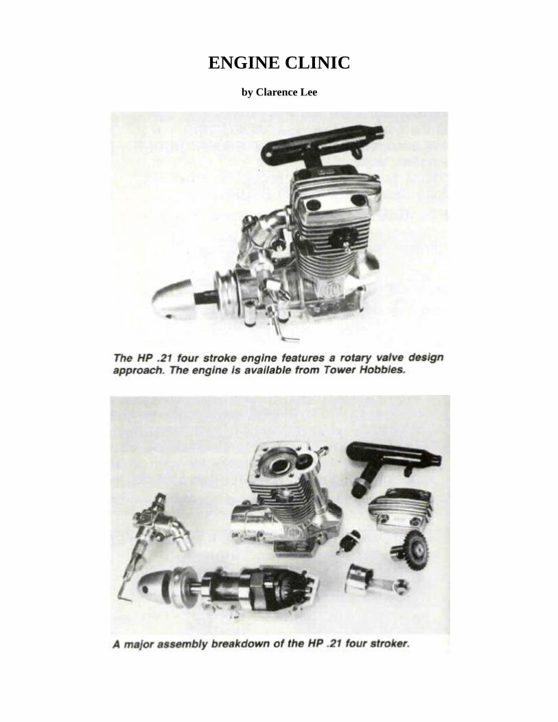
ENGINE CLINIC
by Clarence Lee

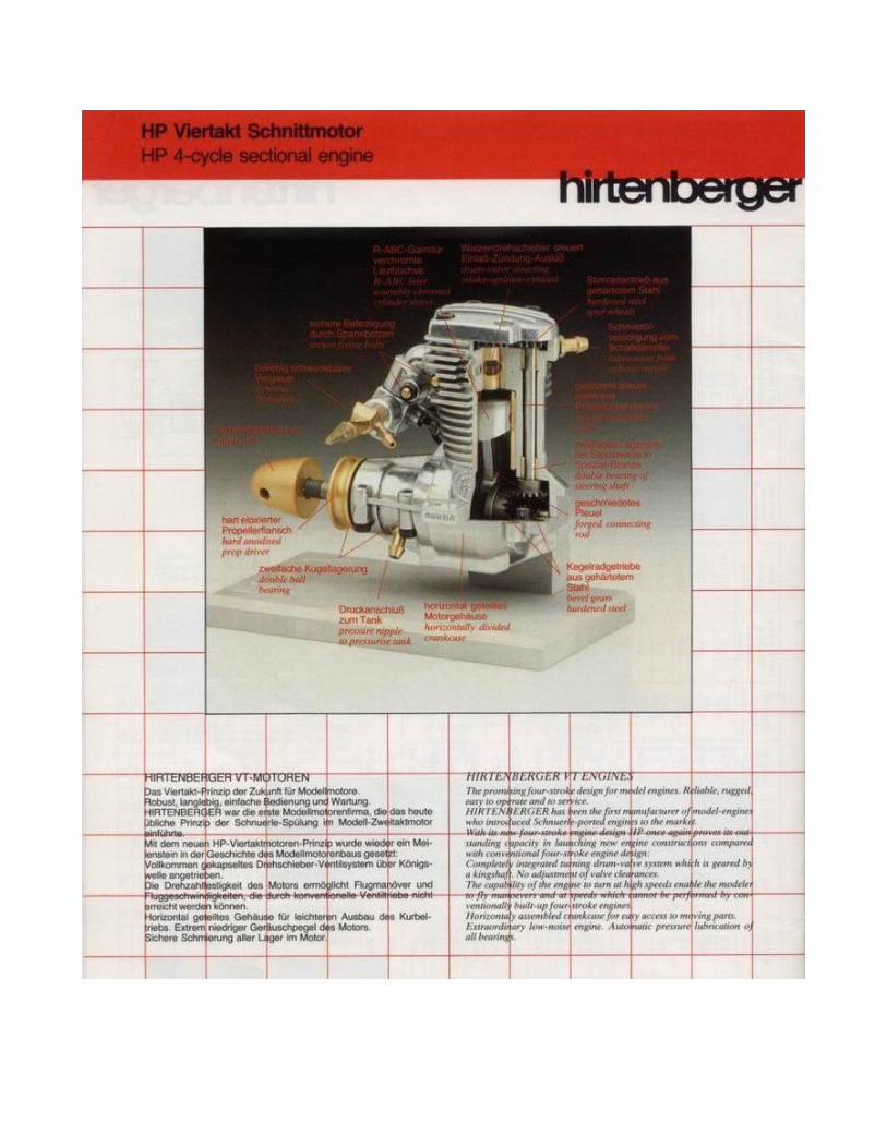
Fifteen years ago, in 1968, Hirtenberger Patronenfabrik of Austria introduced the first commercially produced Schnuerle ported two stroke model engine to the hobby market. Although several individual modelers here in the U.S. and in Europe had been working with Schnuerle ported engines in U-control speed, (Bill Wisniewski, head of K & B’s engine design department and his “Wart” .15 being the most notable). Hirtenberger was the first manufacturer to mass produce a Schnuerle ported R/C engine. This was the start of the trend that now finds all high performance two stroke model engines using various modifications of the Schnuerle porting. Hirtenberger’s first engine was of .61 Cu. in. displacement and featured a rather unusual large diameter drum rear intake. The carburetor being mounted on a downward angle from the bottom of the intake casting did present mounting and fuel tank location problems in an R/C aircraft. The engine was a real powerhouse, however. This engine was shortly followed with a more conventional front rotor intake design that became a very popular selling engine here in the U.S. Over the years, Hirtenberger has expanded their line of engines to include engines from .20 Cu. in. through a 1.20 cu. in. inline twin cylinder engine as well as engines for marine and R/C car use.
This past month I received Hirtenberger’s latest development —a .21 cu. in. displacement four stroke engine. As with Hirtenberger’s original Schnuerle ported engine, they have chosen to depart from the normal design trend and come up with an entirely different method of four stroke induction. Rather than the use of an intake and exhaust valve and the related actuating mechanism, the new HP 21 uses a rotating drum or valve mounted vertically in the head with appropriate openings to time the intake and exhaust. The drum valve is driven by a shaft mounted spur gear that is, in turn, driven by a pair of bevel gears mounted in the rear of the crankcase.
The master gear in the crankcase is driven by an extension of the crankshaft crankpin. The assembly being completely enclosed eliminates the possibility of dirt causing wear to the moving parts and greatly lessens the possibility of damage due to a crash.
Hirtenberger is not the first to market a four stroke engine using a rotary valve type of induction rather than poppet valves but their drum valve does differ from the types used by other manufacturers. Webra first introduced a rotary valve type four stroke two years ago with their .87 Cu. in. Webra T-4. This engine used a variation of the Aspin conical rotary valve used in full size engines. The cone shaped valve is mounted vertically with the inside of the cone being the head of the combustion chamber. A belt driven shaft and bevel gearing, in turn, driving the valve. The English Condor 91 also uses a horizontally mounted cylindrical rotary valve driven directly by a belt on the back of the engine. Both the Webra T-4 and Condor 91 having their driving mechanism exposed to the elements.
Hirtenberger’s new HP 21 is the smallest four stroke engine on the model market. It is a known fact that most four stroke model engines develop about two thirds the power of an equivarent displacement two stroke engine but do have the capability of turning larger propellers in the lower rpm ranges. Four strokes are also limited in rpm capability by the valve mechanism which has a tendency to “float” at rpm levels much over 10,000. Valve float is simply the point where the valves can no longer open and close rapidly enough and begin to stay partially open. Increasing the valve spring pressure helps, but, in turn, increases wear to the cam lobes and valve train in general. By going to a rotary valve intake system the engine, in turn, has higher rpm capability. Something that would be necessary with a smaller displacement four stroke engine. This is the case with the HP 21. One might think that a .21 Cu. in. four stroke engine might not have enough useful power to be practical. This is far from the truth with the HP 21. The Hirtenberger people claim .34 horsepower for the engine at 12,500 rpm. Although not an outstanding figure for a Schnuerle ported two stroke engine, it is the equal to many of the cross flow ported .19’s of just a few years ago.

With the rated horsepower at 12,500, it is obvious that, although of four stroke design, the engine was not to be limited to big props and low rpm operation although the engine still has excellent low speed lugging power characteristic of four stroke engines.
Over the years, after having run many thousands of engines, I do not really find it one of my favorite fun things to do. The little HP 21 was the first engine to come along in a long time that I was actually looking forward to checking out.
I received the engine direct from Hirtenberger in Austria with no accompanying correspondence. Just the instruction booklet printed in four languages. The engine had been run and I imagine it was one of the first production line samples. The serial number of #85 would substantiate this. Although the engine had been run, it seemed to be far from broken-in so I gave it an additional thirty minutes of rich break-in running using a 9/6 Top Flite Super M propeller and Cool Power 10% nitro fuel. Although four stroke engines work better after break-in with lower oil content fuel, I still like 20%-22% oil content for the initial break-in while the parts are polishing together and seating. I have also found that while nitromethane does not give the power increases in a four stroke engine that it does in a two stroke, it is a big aid in the idle and acceleration. I also suspected that as the HP 21 developed its horsepower in the 12,500 rpm range, it might benefit by the use of nitromethane.

After the initial rich break-in, rpm/power checks were begun. Cool Power 10% was used for all checks initially. Actual rpm figures obtained were as follows:
7/6 Top Flite, 14,700;8/6 Top Flite, 12,700; 9/5 Top Flite,10,800;9/6 Top Flite, 10,200;10/6 Top Flite, 8,200;11/6 Top Flite, 6,500;12/6 Top Flite, 5,600.
Needless to say the 11/6 and 12/6 were getting a bit large for the engine but I was curious as to how well the engine would lug the really big props. The 7/6, on the other hand, was a bit small but, since the manufacturer lists the rpm range of the engine as 2,500-15,000 rpm, I wanted to check the high rpm capability. When plotting a power graph it is also necessary to run an engine above and below its maximum rpm/torque limits to determine its horsepower/torque curve. As can be seen in the accompanying power graph, the engine had a very flat horsepower peak developing over one third horsepower between 11,000 and 13,000 rpm with a peak of .35 hp at 12,000-12,500. Maximum torque of 31 oz. in. was obtained at 11,000. Transposed to actual propeller sizes, a 9/6 would appear to be the best prop for the engine. Allowing for unloading in the air, the engine would turn a little under its maximum horsepower peak and slightly above it maximum torque peak. A lot of fellows mistakenly believe that an engine should be propped for its maximum horsepower peak, but this would only be true for all out speed engines. In the case of a sport engine, it is better to run the engine below the horsepower peak and closer to the torque peak. It is torque that turns the prop and allows the use of larger propeller sizes. The aircraft naturally plays a part in proper propeller selection, so possibly a 9/5 or even 10/4 for an antique scale type model would be more practical. The engine can handle up to an 11/6 without overheating if the application should require this size propeller —more on the operating temperature later in the article. It is quite interesting to note that Hirtenberger was not overestimating the power of the engine and state a horsepower figure actually achieved. I have checked many engines over the years that claimed horsepower figures considerably higher than those actually obtainable. Of course, many manufacturers resort to “guestimation” rather than by actual dyno testing.
The engine was very easy starting and, like most four strokes, liked to start “wet.” Unlike most four strokes that seem to start best by flipping backwards - the engine kicks and takes off running in the proper direction - the HP 21 started easiest by flipping in the direction of rotation the same as a two stroke engine. In fact, I could seldom get it to start using the backwards flip start method. Flipping in the direction of rotation following a wet prime in the exhaust would have the engine running in two or three flips. Due to the extensive amount of starting and stopping of the engine, I did resort to the electric starter after the first five or six starts to speed up the testing. A finger over the intake while hitting with the starter and quickly removing the finger had the engine running in one or two seconds every time. I. should point out that placement of the carburetor does not make for easy choking of the engine. In fact, there is not enough room between the carburetor intake and top of the front housing for your finger. However, the carburetor can be rotated in the intake elbow and the elbow, in turn, swung to either side, then making it an easy matter to choke the engine. The finger manipulation necessary does leave the thumb sticking towards the prop and you do have to be careful not to get bit as I did a couple of times.

Throughout the entire testing the engine ran very smoothly and cleanly. There was no trace of detonation or tendency for the engine to kick and throw the prop. If the mixture were leaned excessively, the engine would just stop running.
The only blemish on the whole engine performance was the idle. I could not get the engine to idle reliably below 3,500 with 4,000 being a safer figure. This was using the 9/6 prop. Of course, being a four stroke engine with a firing impulse every other stroke, you are getting a 2,000 rpm sound which makes the engine seem to be running much slower than it actually is. This was also rather deceiving at the high end with the engine turning 14,700 rpm, it was hard to believe it was turning this rpm with the 7,350 rpm sound.
Up until this time I had been using the Cool Power 10% fuel. Being unable to get the engine to idle below the 3,500 rpm figure, I now diluted the Cool Power with 50% methanol alcohol giving an oil content of 11% and nitro content of 5%. Although the idle did improve very slightly with the drop in oil content, it was nothing significant. Power checks were also made with the 9/6 and 8/6 props. Rpm was down about 400 indicating the engine did like more nitro. So some fuel was mixed using 10% oil (Klotz), 10% nitromethane, 2% Propylene oxide (an igniter), and the balance alcohol. Rpm was back up to the same as with the Cool Power and idle now improved to the point where it would reliably hold 3,500 rpm. With the starting battery connected, it would idle reliably at 2,700. A variety of glow ~plugs were tried including the glow plug that came in the engine, a K & B, Fox, Fireball hot, Glow Bee, and O.S. Four-stroke plug. Plugs did not seem to make that much difference. The O.S. plug seemed to work the best of all but not that much better over the plug that came in the engine. The Fireball hot did improve the idle but had a tendency for the engine to misfire at the top end.
I attribute the engine’s non critical plug tendency to the rotary valve drum intake. The glow plug is only exposed to the combustion chamber when the port in the drum valve lines up with an opening that leads to the glow plug; acutally, just about one revolution of the engine. The glow plug being shut off from the combustion chamber during the next revolution.
Although 3,500 might be a little higher than some fellows might like, it is low enough for most applications. If a lower idle is required it might be necessary to use an on-board power supply for the glow plug. Possibly with more running time a lower idle could be achieved. I did accumulate about a total of two hours running on the engine but it still had a tendency to lose 200-300 rpm after warm-up. That is, starting up from cold, the engine would hit a 200-300 rpm higher figure than after warm-up. Since compression was exceptional and nothing seemed to be tight I would assume that the engine was still not fully broken-in.
Although the noise level is very low with an open exhaust, the engine does come with a small muffler that looks like a small CO2 bottle. As small as the muffler is, it did lower the exhaust level considerably — enough so that you could hear the propeller singing. Surprisingly, the muffler did not cause any loss of power with prop sizes over 8/6. With the 7/6 there was about a 200 rpm drop. All testing was done with the muffler installed in order to utilize the muffler pressure for pressurizing the fuel tank. Incidentally, while checking the idle, both muffler pressure and no pressure was tried.

Something I did think was a little strange is the manufacturer’s recommendation for the method of using muffler pressure. You will note in the accompanying pictures of the engine that a pressure fitting is installed in the head of the engine. A piece of tubing is connected between this fitting and the muffler pressure fitting. A line is then run from the crankcase vent fitting on the bottom of the crankcase (between the front and rear bearings) to the tank. Muffler pressure enters the gear box area —passes through the hollow shaft that drives the rotary drum valve —through the crankcase and on to the tank. Evidentally, this is done to keep the spur gears in the head lubricated. However, metal particles from normal wear, gunk in the crankcase, and a lot of combustion residue from the engine and muffler, are all forced back through the engine and into the fuel tank. With this set-up, a fine screen filter between the fuel tank and carburetor would certainly be a must. Having some real reservations as to the practicality of this set-up, I chose to take the muffler pressure directly off the muffler fitting as is standard practice. A shot of oil in the head fitting every half dozen flights should take care of lubrication of the rotary valve spur gears. In fact, I imagine normal fuel leakage past the rotary valve might provide sufficient lubrication.
One of the reasons we can get away with lower oil content fuel in a four stroke engine is due to the lower operating temperature. Firing every other stroke, the incoming fuel charge helps to cool the piston between firing impulses. Most two stroke glow engines operate with the cylinder head

temperature running between 360o~3800. With a lean run, the temperature can go well into the 400~ range. While really lugging the HP 21 down with the 12/6 prop, a cylinder head temperature check was made. The engine was running surprisingly cool indicating only 2100 at the glow plug washer and 2200 at the exhaust stub. This was with a fully lean, maximum power mixture. Richening the mixture lowered the temperatures by 300. Herein is one of the big advantages of a four stroke engine - lugging larger props without overheating.
The manufacturer lists the bore of the engine as 16.6 mm (.654”) and the stroke as 16 mm (.630) for a displacement of .21 cu. in. Our particular engine had a bore of .654 but a slightly longer stroke of .638. However, this slight increase in the stroke does not significantly increase the displacement (.212 versus .214 cu. in.).
The aluminum diecast crankcase/cylinder is a bit unusual in that, rather than being of one piece design with a removable back plate or back plate and front housing, it splits into two pieces along the crankshaft centerline. The crankcase half and cylinder head is a one piece unit. This was evidently done to provide rigidity and maintain proper alignment of the rotary valve drive gearing mechanism. Other manufacturers have used split crankcase halves in previous years. One example is the late Bill Atwood’s Triumph .49 and .51 designs of the late 1940’s. The Atwood Triumph engines also had a removable front and back plate. Bill Atwood later incorporated this type of crankcase in his Cox Concept .15 and .40 designs that were never put into production by Cox.

With the split crankcase and integral head, I figured the engine would have a chromed cylinder bore without a separate liner or sleeve. However, this is not the case with the H.P. Close inspection indicates that the engine has what appears to be a chrome plated brass sleeve either cast into the casting or pressed in. I could not determine any conventional way of removing the sleeve and did not want to try forcing things with possible resultant damage. If it were cast in, then there would be no way for its removal. There are two holes, approximately 1/8”, drilled 1800 apart in the lower end of the sleeve which may have been index holes to locate the sleeve while the crankcase was being cast or, possibly, have to do with the installation / withdrawal of the sleeve. As the parts sheet that accompanied the engine does not list a separate sleeve, only the complete cylinder casting, I assume that the sleeve is not removable.
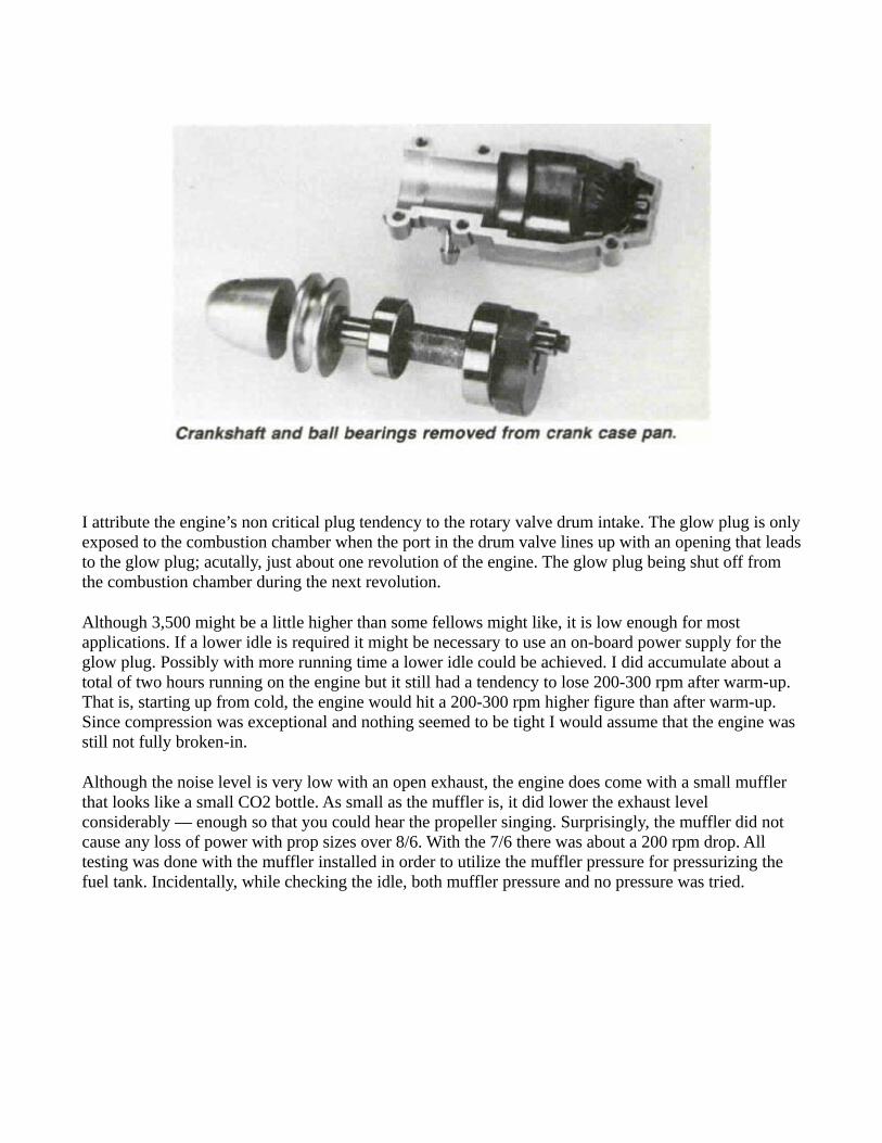
The two crankcase halves do not use a gasket and are assembled with Loctite. This type of split crankcase certainly makes bearing installation a snap as you have only to lay the crankshaft/bearing assembly into place and join the two halves together.
The integral cylinder head is perfectly flat bottomed in design and the bottom end of the rotary valve fits flush with the inside of the head surface. The piston at top center only clears the bottom of the head by .010” on this engine forcing the air/fuel mixture into the hollow drilled rotary valve. This small opening is .215” in diameter and approximately .195” deep. So, in effect, the inside of the head surface is an extremely wide squish surface forcing the fuel mixture into the small .215” x .195” tubular chamber. The top side wall of the chamber has a .185” square opening that lines up with the exhaust port, intake port, and glow plug port as the rotary valve rotates.
Past experience with combustion chamber shapes whould lead me to believe that modification to this small tubular combustion chamber shape would result in a power increase. In fact, one of my first projects, after RCM’s chief photographer Dick Tichenor gets through taking the photographs to accompany this article, will be to try a modification to the rotary valve combustion chamber shape. An extended “Trumphet” shape. Maybe it will result in a power loss but you do not know without trying.
The full stroke compression ratio of the engine figures to be approximately 9.77-1. With the small tubular combustion chamber shape and the glow plug on the side of the head, trying to fill the combustion chamber with oil to get a volume measurement posed some problems in eliminating possible air bubbles.
With a two stroke engine, compression ratio is usually figured from the time the exhaust port closes. That is, if an engine has a stroke of .800” and the exhaust port height was .200”, then .600” would be used to compute the compression ratio. In the case of a four stroke engine, the compression stroke starts as the intake port closes which can be anywhere from close to bottom center to 450 after bottom center. In the case of the HP 21, the intake closes 350 after bottom center. Actual timing of the HP 21 intake opens at 350 before top center and closes 350 after bottom center. The exhaust opens 350 before bottom center and closes 350 after top center with an overlap period where both the exhaust and intake are partially open of 700. The intake port closes 350 after bottom center results in a vertical piston travel of only .040”, hence the reason for the full stroke being used to calculate compression ratio.
The piston appears to be a high silicon aluminum, permanent mold casting and uses a Dykes ring. With the chrome plated brass sleeve, aluminum piston, and Dykes ring, you might consider the engine of ABCD design — a term first coined by World Engines for some of the Super Tigre line, if I recall correctly. The piston is not a lapped or tight fit in the cylinder as with a true ABC design having a running clearance of .001” and relying on the Dykes ring for sealing. This does make fitting of the

piston/sleeve a somewhat easier task production wise. This particular engine had an exceptional compression seal and, until disassembling the engine, I thought it would have a lapped type piston/sleeve fit. I was quite surprised to find the engine used a Dykes ring. Due to the rotary valve allowing no compression leakage as do regular poppet valves, the engine feels much the same as a two stroke engine with the exception of coming on compression every other stroke.
The connecting rod is machined from bar stock aluminum and is of quite massive proportions. Only the big end is bronze bushed with the wrist pin end running in the aluminum rod. The steel wrist pin is full floating and used Nylon pads at the ends rather than what has become pretty universal now — Teflon. Why HP chose to use Nylon is a bit puzzling but they evidently felt that, due to the lower operating temperature, Teflon would not be required.
The crankshaft is made of steel, hardened, and finish ground on the bearing surfaces. The crankpin is a separate pressed-in piece and presses into a very massive crank disc that is .195” wide. The crank disc is, in turn, milled on each side of the crankpin to provide counter balance. A small extension on the end of the crankpin drives a bevel gear that meshes with the mating bevel gear that, in turn, drives a shaft and the spur gear rotary valve in the head. The crankshaft is supported by two ball bearings of Japanese manufacture. The rear bearing is 24 mm (.945”) O.D. x 9 mm (.354”) I.D. and the front bearing is 19 mm O.D. (.748”) x 7 mm (.275”) I.D. The front bearing is of the double sealed type to keep foreign matter from entering and, in turn, sealing the crankcase.
The carburetor is of the rotating barrel type that moves in and out as it rotates. An idle mixture adjustment is provided on one side and the high speed mixture adjustment on the opposite side. The carburetor venturi diameter appears quite small at .160” (after working with two stroke carburetors for so many years), but one must remember that four stroke engines have much longer intake and exhaust periods so that large intake and exhaust openings, as used on two stroke engines, are not required.
As can be seen from the accompanying photographs, the HP 21 is of rugged construction and, in my opinion, has a very nice overall appearance. The down sloping intake tube with the inverted carburetor does account for a rather different look. The intake manifold can be removed and the carburetor mounted directly to the head if a particular application that would require this type of mounting should arise.
Four stroke engines certainly seem to be the coming thing judging by all the manufacturers that are now producing them. In the quest for more power, I believe more manufacturers will be turning to rotary valve type designs to overcome the rpm limitations of poppet valves. As with their original HP .61 Schnuerle engine that started the present trend to high performance two stroke engines, the HP 21 four stroke and its big brother the HP 49 not yet released at the time of this writing, has lead the way with the first of what might be considered “high speed” four stroke engines.
The engine is being imported into the U.S. by Tower Hobbies and will sell for a very low $79.98. This is the lowest price four-stroke on the market.
All Contents Copyright © 1983. R/C Modeler Corporation. All Rights Reserved.