Embed Size (px)
Citation preview

Submission folder
Customer Hotline Customer Hotline Hong Kong 8228 8118Macau (Toll free) 00800- 8228 8118
Hilti HDA Submission Folder
Sample Submissionand Approval Form 2 - 3
Product Information 4 - 8
Technical Data 9 - 14
Method Statement 15 - 16
Test Reports according to BS5080HDA-T 17 - 57HDA-TR 58 - 76
European Technical ApprovalHDA-T / - P 77 - 84HDA-TR / - PR 85 - 92
Government Letter 93 - 94
Country of Origin 95
Job Reference 96 - 102
Page 1 of 2
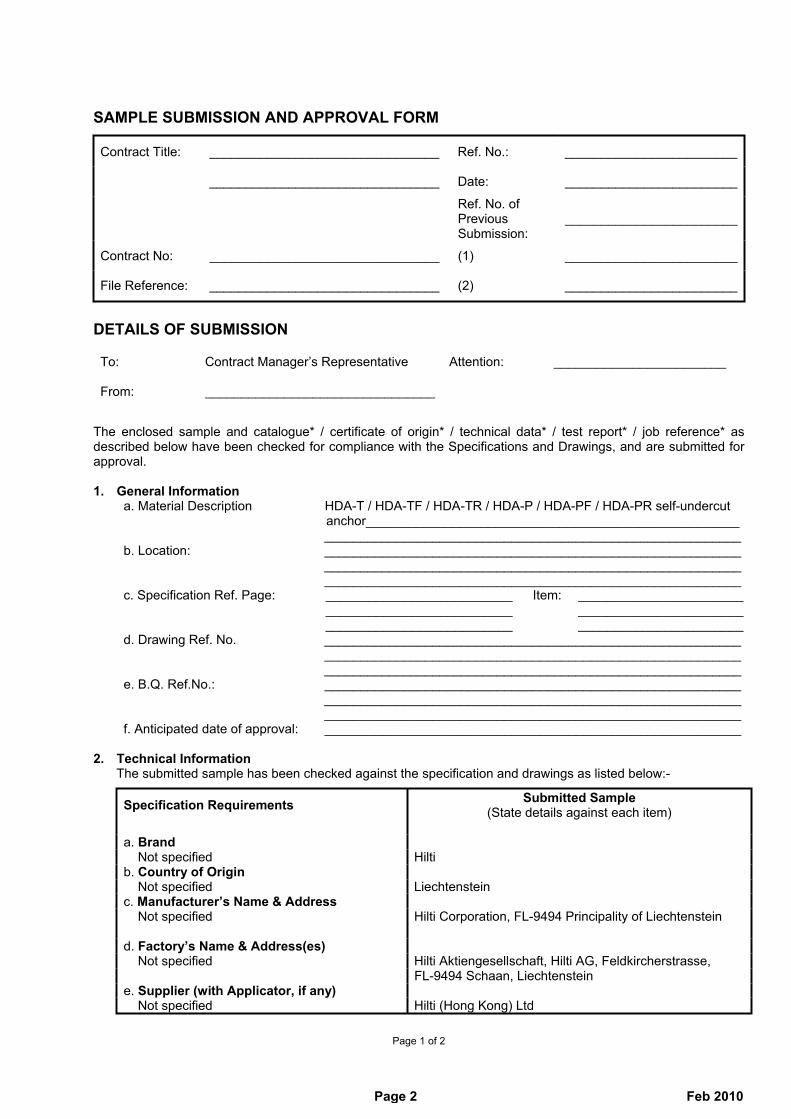
SAMPLE SUBMISSION AND APPROVAL FORM
Contract Title: ________________________________ Ref. No.: ________________________
________________________________ Date: ________________________
Ref. No. of Previous Submission:
________________________
Contract No: ________________________________ (1) ________________________
File Reference: ________________________________ (2) ________________________
DETAILS OF SUBMISSION
To: Contract Manager’s Representative Attention: ________________________
From: ________________________________
The enclosed sample and catalogue* / certificate of origin* / technical data* / test report* / job reference* as described below have been checked for compliance with the Specifications and Drawings, and are submitted for approval.
1. General Information a. Material Description HDA-T / HDA-TF / HDA-TR / HDA-P / HDA-PF / HDA-PR self-undercut anchor____________________________________________________ __________________________________________________________ b. Location: __________________________________________________________ __________________________________________________________ __________________________________________________________ c. Specification Ref. Page: __________________________ Item: _______________________ __________________________ _______________________ __________________________ _______________________ d. Drawing Ref. No. __________________________________________________________ __________________________________________________________ __________________________________________________________ e. B.Q. Ref.No.: __________________________________________________________ __________________________________________________________ __________________________________________________________ f. Anticipated date of approval: __________________________________________________________
2. Technical Information The submitted sample has been checked against the specification and drawings as listed below:-
Specification Requirements Submitted Sample (State details against each item)
a. Brand Not specified Hilti b. Country of Origin Not specified Liechtenstein c. Manufacturer’s Name & Address Not specified Hilti Corporation, FL-9494 Principality of Liechtenstein
d. Factory’s Name & Address(es) Not specified Hilti Aktiengesellschaft, Hilti AG, Feldkircherstrasse, FL-9494 Schaan, Liechtenstein e. Supplier (with Applicator, if any) Not specified Hilti (Hong Kong) Ltd
Page 2 Feb 2010

Page 2 of 2
f. Appearance Not specified According to the sample submitted
g. Color + Not specified NIL
h. Specification Not specified Attached
i. Manufacturer’s Catalogue Not specified Attached
j. Test Report (Original/Certificated True Copy) Not specified Attached
k. Previous Job Reference Not specified Attached
l. Supplementary Information Not specified NIL
For and on behalf of the Contractor
____________________________ (Quality Control Manager)
CONTRACT MANAGER’S COMMENTS To:From: Contract Manager’s Representative: ________________________________
On the basis of the sample and information given, the above sample submitted is:
(1) * Approved. (2) * Not approved because ____________________________________________________ _______________________________________________________________________ _______________________________________________________________________ Remarks: _______________________________________________________________________ _______________________________________________________________________ _______________________________________________________________________
Approval does not alter the requirements of the Contract Contract Manager’s Representative: ____________________________
_____________________________ Date:
cc. _______________________________________ _______________________________________ _______________________________________ _______________________________________
(* Delete if appropriate) (+ For glass or vitreous mosaic tiles, the contractor is required to confirm the colour range(s) of the submitted sample, i.e. a) light and or medium; or b) dark)
Page 3 Feb 2010

Anchoring Systems
243 Customer Hotline: Hong Kong 8228 8118 Macau 00800 8228 8118 (Mon - Fri 8:30 am - 6:00 pm / Sat 8:30 am - 1:00 pm) | Hilti online: www.hilti.com.hk
Technical data Recommended load, F30 (kN), non-cracked concrete at 30N/mm², safety factor(�)=3
HDA self-undercut anchorBase material■ Cracked or non-cracked concrete■ Hard natural stone
Use■ For fastening heavy loads, e.g. structural canopy, steel construction and curtain wall, etc.■ Dynamic conditions, e.g. with vibratory or windy condition
Material■ Steel Strength 8.8, galvanized 5 µm(M10-M20)■ Steel Strength 8.8, sherardized 53 µm (M10-M16)■ Stainless Steel A4 - 80 (M10-M16)
Benefits■ Self undercutting anchor:
Simple and quick undercutting operation results in a keying effect for maximum security even in cracked concrete
■ Allows small spacing and edge distances: Low expansion forces – performs like a cast-in headed stud
■ Simple installation: No complicated, specialized undercutting tools required■ Built-in setting control for reliable installation■ Load can be applied immediately after setting
Fully removable
Remarks:1) All the data applies to no edge distance, spacing and other influences 2) For detail design method and cracked concrete information, please refer to Fastening Technology Manual3) M20 version is only available to galvanized 5µm, i.e. HDA-T / HDA-P
Installation procedures
Model Size M10 M12 M16 M20
HDA-T / HDA-TF
Tensile Load, Nrec 16.9 24.6 46.2 73.2
Shear Load, Vrec 23.8 29.3 51.3 77.0
HDA-TR
Tensile Load, Nrec 16.9 24.6 46.2 -
Shear Load, Vrec 26.0 31.9 55.7 -
HDA-P / HDA-PF
Tensile Load, Nrec 16.9 24.6 46.2 73.2
Shear Load, Vrec 8.1 11.0 22.7 35.9
HDA-PR
Tensile Load, Nrec 16.9 24.6 46.2 -
Shear Load, Vrec 8.4 12.5 23.1 -
HDA-T/-TR/-TF
HDA-P/-PR/-PF
Markingdf
df
tfix
tfix
hef
hef
hmin
hmin
l
l
Approvals
Page 4 Feb 2010

Anchoring Systems
244Customer Hotline: Hong Kong 8228 8118 Macau 00800 8228 8118 (Mon - Fri 8:30 am - 6:00 pm / Sat 8:30 am - 1:00 pm) | Hilti online: www.hilti.com.hk
10
Anchor TE 24/ TE 35 TE 40/ TE 56 TE60-ATC TE 70/ TE 75 TE 76/ TE80-ATC Stop drill bit Setting tool TE 25 TE40-AVR TE56-ATC TE70-ATC TE76-ATC (1st gear) max. hammering powerHDA-P 20-M10x100/20 ■ ■ TE-C-HDA-B 20x100 TE-C-HDA-ST 20 M10 ■ ■ TE-Y-HDA-B 20x100 TE-Y-HDA-ST 20 M10HDA-T 20-M10x100/20 ■ ■ TE-C-HDA-B 20x120 TE-C-HDA-ST 20 M10 ■ ■ TE-Y-HDA-B 20x120 TE-Y-HDA-ST 20 M10HDA-P 22-M12x125/30 ■ ■ TE-C-HDA-B 22x125 TE-C-HDA-ST 22 M12 ■ ■ TE-Y-HDA-B 22x125 TE-Y-HDA-ST 22 M12HDA-T 22-M12x125/30 ■ ■ TE-C-HDA-B 22x155 TE-C-HDA-ST 22 M12 ■ ■ TE-Y-HDA-B 22x155 TE-Y-HDA-ST 22 M12HDA-P 22-M12x125/50 ■ ■ TE-C-HDA-B 22x125 TE-C-HDA-ST 22 M12 ■ ■ TE-Y-HDA-B 22x125 TE-Y-HDA-ST 22 M12HDA-T 22-M12x125/50 ■ ■ TE-C-HDA-B 22x175 TE-C-HDA-ST 22 M12 ■ ■ TE-Y-HDA-B 22x175 TE-Y-HDA-ST 22 M12HDA-P 30-M16x190/40 ■ ■ ■ ■ TE-Y-HDA-B 30x190 HDA-T 30-M16x190/40 ■ ■ ■ ■ TE-Y-HDA-B 30x230 HDA-P 30-M16x190/60 ■ ■ ■ ■ TE-Y-HDA-B 30x190
TE-Y-HDA-ST 30 M16
HDA-T 30-M16x190/60 ■ ■ ■ ■ TE-Y-HDA-B 30x250HDA-P 37-M20x250/50 ■ ■ ■ TE-Y-HDA-B 37x250 HDA-T 37-M20x250/50 ■ ■ ■ TE-Y-HDA-B 37x300 HDA-P 37-M20x250/100 ■ ■ ■ TE-Y-HDA-B 37x250
TE-Y-HDA-ST 37 M20
HDA-T 37-M20x250/100 ■ ■ ■ TE-Y-HDA-B 37x350
Tool and machines
HDA-T and HDA-P (Galvanized version 5µm)
HDA-TR and HDA-PR (Stainless steel version A4-80)
HDA-TF and HDA-PF (Sherardized version 53µm)System components
Anchor TE 24/ TE 35 TE 40/ TE 56 TE60-ATC TE 70/ TE 75 TE 76/ TE80-ATC Stop drill bit Setting tool TE 25 TE40-AVR TE56-ATC TE70-ATC TE76-ATC (1st gear) max. hammering powerHDA-PR20-M10x100/20 ■ ■ ■ TE-C-HDA-B 20x100 TE-C-HDA-ST 20 M10 ■ TE-Y-HDA-B 20x100 TE-Y-HDA-ST 20 M10HDA-TR20-M10x100/20 ■ ■ ■ TE-C-HDA-B 20x120 TE-C-HDA-ST 20 M10 ■ TE-Y-HDA-B 20x120 TE-Y-HDA-ST 20 M10HDA-PR22-M12x125/30 ■ ■ ■ TE-C-HDA-B 22x125 TE-C-HDA-ST 22 M12 ■ TE-Y-HDA-B 22x125 TE-Y-HDA-ST 22 M12HDA-TR22-M12x125/30 ■ ■ ■ TE-C-HDA-B 22x155 TE-C-HDA-ST 22 M12 ■ TE-Y-HDA-B 22x155 TE-Y-HDA-ST 22 M12HDA-PR22-M12x125/50 ■ ■ ■ TE-C-HDA-B 22x125 TE-C-HDA-ST 22 M12 ■ TE-Y-HDA-B 22x125 TE-Y-HDA-ST 22 M12HDA-TR22-M12x125/50 ■ ■ ■ TE-C-HDA-B 22x175 TE-C-HDA-ST 22 M12 ■ TE-Y-HDA-B 22x175 TE-Y-HDA-ST 22 M12HDA-PR30-M16x190/40 ■ ■ ■ ■ TE-Y-HDA-B 30x190 HDA-TR30-M16x190/40 ■ ■ ■ ■ TE-Y-HDA-B 30x230 HDA-PR30-M16x190/60 ■ ■ ■ ■ TE-Y-HDA-B 30x190
TE-Y-HDA-ST 30 M16
HDA-TR30-M16x190/60 ■ ■ ■ ■ TE-Y-HDA-B 30x250
Anchor TE 24/ TE 35 TE 40/ TE 56 TE60-ATC TE 70/ TE 75 TE 76/ TE80-ATC Stop drill bit Setting tool TE 25 TE40-AVR TE56-ATC TE70-ATC TE76-ATC (1st gear) max. hammering powerHDA-PF 20-M10x100/20 ■ TE-C-HDA-B 20x100 HDA-TF 20-M10x100/20 ■ TE-C-HDA-B 20x120
TE-C-HDA-ST 20 M10
HDA-PF 22-M12x125/30 ■ TE-C-HDA-B 22x125 HDA-TF 22-M12x125/30 ■ TE-C-HDA-B 22x155 HDA-PF 22-M12x125/50 ■ TE-C-HDA-B 22x125
TE-C-HDA-ST 22 M12
HDA-TF 22-M12x125/50 ■ TE-C-HDA-B 22x175 HDA-PF 30-M16x190/40 ■ ■ TE-Y-HDA-B 30x190 HDA-TF 30-M16x190/40 ■ ■ TE-Y-HDA-B 30x230 HDA-PF 37-M20x190/50 ■ ■ TE-Y-HDA-B 30x190
TE-Y-HDA-ST 30 M16
HDA-TF 37-M20x190/60 ■ ■ TE-Y-HDA-B 30x250
Page 5 Feb 2010

Anchoring Systems
245 Customer Hotline: Hong Kong 8228 8118 Macau 00800 8228 8118 (Mon - Fri 8:30 am - 6:00 pm / Sat 8:30 am - 1:00 pm) | Hilti online: www.hilti.com.hk
HDA-T Programme Min. base Anchor Drill bit material age Anchor Tighten. Max. Clear- Width nom. thickness, depth, lenght, Head torque fasten. ance across dia., do hmin hef I mark Tinst thk. tfix hole, df flats,Sw Package Order designation Item no (mm) (mm) (mm) (mm) (Nm) (mm) (mm) (pcs)
HDA-T galvanized version (min. 5µm) 20 170 100 150 I 50 20 21 17 12 HDA-T 20-M10x100/20 331545 22 190 125 190 L 80 30 23 19 8 HDA-T 22-M12x125/30 331548 22 190 125 210 N 80 50 23 19 8 HDA-T 22-M12x125/50 331549 ★ 30 270 190 275 R 120 40 32 24 4 HDA-T 30-M16x190/40 331552 30 270 190 295 S 120 60 32 24 4 HDA-T 30-M16x190/60 331553 ★ 37 350 250 360 V 300 50 40 30 2 HDA-T 37-M20x250/50 339267 37 350 250 410 X 300 100 40 30 2 HDA-T 37-M20x250/100 339268 ★
HDA-TF sherardized version (min. 53µm) 20 170 100 150 I 50 20 21 17 12 HDA-TF 20-M10x100/20 339361 ★ 22 190 125 190 L 80 30 23 19 8 HDA-TF 22-M12x125/30 339362 ★ 22 190 125 210 N 80 50 23 19 8 HDA-TF 22-M12x125/50 339363 ★ 30 270 190 275 R 120 40 32 24 4 HDA-TF 30-M16x190/40 339364 ★ 30 270 190 295 S 120 60 32 24 4 HDA-TF 30-M16x190/60 339365 ★
HDA-TR A4-80 stainless steel version 20 170 100 150 I 50 20 21 17 12 HDA-TR 20-M10x100/20 339351 22 190 125 190 L 80 30 23 19 8 HDA-TR 22-M12x125/30 339352 22 190 125 210 N 80 50 23 19 8 HDA-TR 22-M12x125/50 339353 ★ 30 270 190 275 R 120 40 32 24 4 HDA-TR 30-M16x190/40 339354 30 270 190 295 S 120 60 32 24 4 HDA-TR 30-M16x190/60 339355 ★
HDA-P Programme
HDA-P galvanized version (min. 5µm) 20 170 100 150 I 50 20 12 17 12 HDA-P 20-M10x100/20 331544 ★ 22 190 125 190 L 80 30 14 19 8 HDA-P 22-M12x125/30 331546 ★ 22 190 125 210 N 80 50 14 19 8 HDA-P 22-M12x125/50 331547 ★ 30 270 190 275 R 120 40 18 24 4 HDA-P 30-M16x190/40 331550 ★ 30 270 190 295 S 120 60 18 24 4 HDA-P 30-M16x190/60 331551 ★ 37 350 250 360 V 300 50 22 30 2 HDA-P 37-M20x250/50 339265 ★ 37 350 250 410 X 300 100 22 30 2 HDA-P 37-M20x250/100 339266 ★
HDA-PF sherardized version (min. 53µm) 20 170 100 150 I 50 20 12 17 12 HDA-PF 20-M10x100/20 339356 ★ 22 190 125 190 L 80 30 14 19 8 HDA-PF 22-M12x125/30 339357 ★ 22 190 125 210 N 80 50 14 19 8 HDA-PF 22-M12x125/50 339358 ★ 30 270 190 275 R 120 40 18 24 4 HDA-PF 30-M16x190/40 339359 ★ 30 270 190 295 S 120 60 18 24 4 HDA-PF 30-M16x190/60 339360 ★
HDA-PR A4-80 stainless steel version 20 170 100 150 I 50 20 12 17 12 HDA-PR 20-M10x100/20 339346 ★ 22 190 125 190 L 80 30 14 19 8 HDA-PR 22-M12x125/30 339347 ★ 22 190 125 210 N 80 50 14 19 8 HDA-PR 22-M12x125/50 339348 ★ 30 270 190 275 R 120 40 18 24 4 HDA-PR 30-M16x190/40 339349 ★ 30 270 190 295 S 120 60 18 24 4 HDA-PR 30-M16x190/60 339350 ★
★ Special RequestPage 6 Feb 2010

Anchoring Systems
246Customer Hotline: Hong Kong 8228 8118 Macau 00800 8228 8118 (Mon - Fri 8:30 am - 6:00 pm / Sat 8:30 am - 1:00 pm) | Hilti online: www.hilti.com.hk
10
★ Special Request
Required tools
Anchor Stop drill bit Setting tool Anchor description Order designation Item no Package Order designation Item no Package (pcs) (pcs) HDA-T 20-M10x100/20 TE-C-HDA-B 20x100 332089 ★ 1 TE-C-HDA-ST 20-M10 331843 1 HDA-TF / -TR 20-M10x100/20 TE-Y-HDA-B 20x100 237449 ★ 1 TE-Y-HDA-ST 20-M10 287133 1 HDA-T 22-M12x125/30 TE-C-HDA-B 20x120 332090 1 TE-C-HDA-ST 22-M12 331844 1 HDA-TF / -TR 22-M12x125/30 TE-Y-HDA-B 20x120 237450 1 TE-Y-HDA-ST 22-M12 287134 1 HDA-T 22-M12x125/50 TE-C-HDA-B 22x125 332091 ★ 1 TE-Y-HDA-ST 30-M16 331846 1 HDA-TF / -TR 22-M12x125/50 TE-Y-HDA-B 22x125 237451 ★ 1 TE-Y-HDA-ST 37-M20 339269 1 HDA-T / -TF / -TR 30-M16x190/40 TE-C-HDA-B 22x155 332092 1 TE-Y-HDA-ST 30-M16 331846 1 HDA-T / -TF / -TR 30-M16x190/60 TE-Y-HDA-B 22x155 237452 1 TE-Y-HDA-ST 30-M16 331846 1 HDA-T 37-M20x250/50 TE-C-HDA-B 22x175 332093 ★ 1 TE-Y-HDA-ST 37-M20 339269 1 HDA-T 37-M20x250/100 TE-Y-HDA-B 22x175 237453 ★ 1 TE-Y-HDA-ST 37-M20 339269 1 HDA-P 20-M10x100/20 TE-Y-HDA-B 30x190 332097 ★ 1 TE-Y-HDA-ST 20-M10 287133 1 HDA-PF / -PR 20-M10x100/20 TE-Y-HDA-B 30x230 332098 1 TE-C-HDA-ST 20-M10 331843 1 HDA-P 22-M12x125/30 TE-Y-HDA-B 30x250 332099 ★ 1 TE-Y-HDA-ST 22-M12 287134 1 HDA-PF / -PR 22-M12x125/30 TE-Y-HDA-B 37x250 339270 ★ 1 TE-C-HDA-ST 22-M12 331844 1 HDA-P 22-M12x125/50 TE-Y-HDA-B 37x300 339271 1 TE-Y-HDA-ST 22-M12 287134 1 HDA-PF / -PR 22-M12x125/50 TE-Y-HDA-B 37x350 339272 ★ 1 TE-C-HDA-ST 22-M12
Accessories
Anchor Removal tool Grinding tool Anchor description Order designation Item no Package Order designation Item no Package (pcs) (pcs) HDA-T / -P M10 TE-C-HDA-RT 20-M10 333433 ★ 1 TE-C-HDA-GT 20 333439 ★ 1 HDA-T / -P M12 TE-C-HDA-RT 22-M12 333434 ★ 1 TE-C-HDA-GT 22 333440 ★ 1 HDA-T / -P M16 TE-C-HDA-RT 30-M16 333435 ★ 1 TE-C-HDA-GT 30 333441 ★ 1 HDA-T / -P M20 TE-C-HDA-RT 37-M20 339273 ★ 1 - - -
Page 7 Feb 2010

Anchoring Systems
247 Customer Hotline: Hong Kong 8228 8118 Macau 00800 8228 8118 (Mon - Fri 8:30 am - 6:00 pm / Sat 8:30 am - 1:00 pm) | Hilti online: www.hilti.com.hk★ Special Request
The HDA dynamic undercut anchor system
HDA-T or HDA-P + dynamic set +
Hilti HIT-HY150 undercut anchor hybrid mortar
HDA dynamicFor anchoring dynamic loads in cracked concrete
Base materials Approval■ Cracked and uncracked concrete Z-21.1-1693
Applications■ Anchoring dynamic loads, e.g. elevator installation, conveyor systems,
cranes, machine and plant installation
Material■ Dynamic set: electrogalvanized steel
Setting instructionsBenefits■ Easy to install, even for multiple fastenings■ Optimum load transfer through injection of Hilti HIT-HY 150 and use of concave washer■ Approvals for an unlimited number of load cycles■ Uses the standard HDA undercut anchor in conjunction with a special
dynamic set and Hilti HIT-HY 150
Dynamic SetLarge washers for filling; centering washer, nut and safety nutDesignation Package Item no. contents
Dynamic-Set M10 2 369201 ★Dynamic-Set M12 2 369202 ★Dynamic-Set M16 2 369203 ★Dynamic-Set M20 2 369204 ★ * Diameter of large washer M10: 42 mm, M12: 44 mm, M16: 52 mm, M20: 60 mm
Z-21.1-1693Hilti
Institut fürMassivbauTechnischeUniversitätDarmstadt
*
HDA-T dynamic set
For proper installation of HDA anchor and proper use of HIT-HY 150, contact Hilti
Page 8 Feb 2010

56Is
sue
2007
/08
HD
A s
elf-
un
der
cut
anch
or
Fea
ture
s:
- ke
ying
hol
d
- co
mpl
ete
syst
em
- lo
w e
xpan
sion
forc
e (t
hus
smal
l edg
e di
stan
ce /
spa
cing
)
- au
tom
atic
und
ercu
tting
(w
ithou
t spe
cial
und
ercu
tting
too
l)
- se
tting
mar
k on
anc
hor
for
cont
rol (
easy
and
saf
e)
- su
itabl
e fo
r te
nsio
n zo
ne
- pe
rfor
man
ce o
f a h
eade
d st
ud
- te
st r
epor
ts: f
ire r
esis
tanc
e, fa
tigue
, sho
ck, s
eism
ic
- co
mpl
etel
y re
mov
able
- H
DA
-T/-
TR
/-T
F: t
hrou
gh-f
aste
ning
- H
DA
-P/-
PR
/-P
F: p
re-s
ettin
g
Mat
eria
l:
HD
A-T
/-P
: -
cold
-for
med
ste
el, g
rade
8.8
, gal
vani
sed
min
. 5m
HD
A-T
R/-
PR
-
stai
nles
s st
eel,
A4-
80 g
rade
; 1.4
401,
1.4
571,
1.4
404
(S
S 3
16, S
S 3
16 T
i)
HD
A-T
F/-
PF
- ca
rbon
ste
el, s
hera
rdis
ed 5
3m
acc
ordi
ng to
AS
TM
A15
3 C
L.C
dra
ft D
IN E
N 1
3811
HD
A-P
/-P
R/-
PF
anc
hor
for
pre-
setti
ng
HD
A-T
/-T
R/-
TF
anc
hor
for
thro
ugh-
fast
enin
g
Con
cret
eT
ensi
on z
one
F
atig
ue
Sho
ck
Sei
smic
Clo
se e
dge
dist
ance
/ sp
acin
g
Per
form
ance
of
a he
aded
stu
dF
ire r
esis
tanc
e (F
180
)H
ilti A
ncho
rpr
ogra
mm
eN
ucle
ar p
ower
pl
ant
appr
oval
Bas
ic lo
adin
g d
ata
(fo
r a
sin
gle
an
cho
r):
HD
A-P
/-P
F (
Gal
v. /
sher
ard
ised
)
All
dat
a o
n t
his
sec
tio
n a
pp
lies
to
conc
rete
: as
spec
ified
in th
e ta
ble
no e
dge
dist
ance
, spa
cing
and
oth
er in
fluen
ces
corr
ect s
ettin
g (S
ee s
ettin
g op
erat
ions
)st
eel f
ailu
re
For
det
aile
d de
sign
met
hod,
see
pag
es 6
3 –
67.
Mea
n u
ltim
ate
resi
stan
ce, R
u,m
[kN
]:co
ncre
te C
20/2
5
An
cho
r si
ze
M10
M12
M16
M20
1)M
10M
12M
16M
201)
Ten
sile
NR
um,s
48.5
70.5
130.
920
4.1
48.5
70.5
130.
920
4.1
She
arV
Rum
,s28
.438
.574
.511
1.1
26.4
37.3
77.7
105.
6
Ch
arac
teri
stic
res
ista
nce
, Rk
[kN
]: c
oncr
ete
C20
/25
An
cho
r si
ze
M10
M12
M16
M20
1)M
10M
12M
16M
201)
Ten
sile
NR
k,s
46.0
67.0
126.
019
9.6
25.0
35.0
75.0
95.1
She
arV
Rk,
s22
.030
.062
.098
.022
.030
.062
.098
.0
Fo
llow
ing
valu
es a
cco
rdin
g t
o t
he:
Co
ncr
ete
Cap
acit
y M
eth
od
Des
ign
res
ista
nce
, Rd [
kN]:
con
cret
e f c
k,cu
be=
25
N/m
m2
An
cho
r si
ze
M10
M12
M16
M20
1)M
10M
12M
16M
201)
Ten
sile
NR
d30
.744
.784
.012
7.6
16.7
23.3
50.0
63.4
She
ar V
Rd
17.6
24.0
49.6
78.4
17.6
24.0
49.6
78.4
Rec
om
men
ded
load
, Lre
c [k
N]:
An
cho
r si
ze
M10
M12
M16
M20
1)M
10M
12M
16M
201)
Ten
sile
NR
ec21
.931
.960
.091
.111
.916
.735
.745
.3 S
hear
VR
ec12
.617
.135
.456
.012
.617
.135
.456
.0
1)M
20 v
ersi
on is
onl
y av
aila
ble
galv
anis
ed 5
m
.
crac
ked
co
ncr
ete
no
n-c
rack
ed c
on
cret
e
conc
rete
f ck,
cube
= 2
5 N
/mm
2
Issu
e 20
07/0
857
B
HD
A s
elf-
un
der
cut
anch
or
Bas
ic lo
adin
g d
ata
(fo
r a
sin
gle
an
cho
r):
HD
A-T
/-T
F (
Gal
v. /
sher
ard
ised
)
All
dat
a o
n t
his
sec
tio
n a
pp
lies
to
conc
rete
: as
spec
ified
in th
e ta
ble
no e
dge
dist
ance
, spa
cing
and
oth
er in
fluen
ces
fo
r M
10 –
M12
: tfix
= 1
0mm
fo
r M
16: t
fix =
14m
m
for
M20
: tfix
= 2
0mm
co
rrec
t set
ting
(See
set
ting
oper
atio
ns)
stee
l fai
lure
For
det
aile
d de
sign
met
hod,
see
pag
es 6
3 -
67.
Mea
n u
ltim
ate
resi
stan
ce, R
u,m
[kN
]:co
ncre
te C
20/2
5
An
cho
r si
ze
M10
M12
M16
M20
1)M
10M
12M
16M
201)
Ten
sile
NR
um,s
48.5
70.5
130.
920
4,1
48.5
70.5
130.
920
4,1
She
arV
Rum
,s74
.893
.916
5.7
275,
371
.888
.315
3.2
257,
3
Ch
arac
teri
stic
res
ista
nce
, Rk
[kN
]: c
oncr
ete
C20
/25
An
cho
r si
ze
M10
M12
M16
M20
1)M
10M
12M
16M
201)
Ten
sile
NR
k,s
46.0
67.0
126.
019
9.6
25.0
35.0
75.0
95.1
She
arV
Rk,
s65
.080
.014
0.0
210.
065
.080
.014
0.0
210.
0
Fo
llow
ing
valu
es a
cco
rdin
g t
o t
he:
Co
ncr
ete
Cap
acit
y M
eth
od
Des
ign
res
ista
nce
, Rd [
kN]:
con
cret
e f c
k,cu
be=
25
N/m
m2
An
cho
r si
ze
M10
M12
M16
M20
1)M
10M
12M
16M
201)
Ten
sile
NR
d30
.744
.784
.012
7.6
16.7
23.3
50.0
63.4
She
ar V
Rd
43.3
53.3
93.3
140.
043
.353
.393
.314
0.0
Rec
om
men
ded
load
, Lre
c [k
N]:
con
cret
e f c
k,cu
be=
25
N/m
m2
An
cho
r si
ze
M10
M12
M16
M20
1)M
10M
12M
16M
201)
Ten
sile
NR
ec21
.931
.960
.091
.111
.916
.735
.745
.3 S
hear
VR
ec30
.938
.166
.610
0.0
30.9
38.1
66.6
100.
01)
M20
ver
sion
is o
nly
avai
labl
e ga
lvan
ised
5
m.
Bas
ic lo
adin
g d
ata
(fo
r a
sin
gle
an
cho
r):
HD
A-P
R (
A4-
80 s
tain
less
ste
el)
All
dat
a o
n t
his
sec
tio
n a
pp
lies
to
conc
rete
: as
spec
ified
in th
e ta
ble
no e
dge
dist
ance
, spa
cing
and
oth
er in
fluen
ces
fo
r M
10 –
M12
: tfix
= 1
0mm
; fo
r M
16: t
fix =
14m
m
corr
ect s
ettin
g (S
ee s
ettin
g op
erat
ions
) st
eel f
ailu
re
For
det
aile
d de
sign
met
hod,
see
pag
es 6
3 –
67.
Mea
n u
ltim
ate
resi
stan
ce, R
u,m
[kN
]:co
ncre
te C
20/2
5
An
cho
r si
ze
M10
M12
M16
M10
M12
M16
Ten
sile
NR
um,s
49.1
68.7
127.
949
.168
.712
7.9
She
arV
Rum
,s28
.438
.574
.526
.437
.377
.7
crac
ked
co
ncr
ete
no
n-c
rack
ed c
on
cret
e
crac
ked
co
ncr
ete
no
n-c
rack
ed c
on
cret
e
Page 9 Feb 2010

58Is
sue
2007
/08
HD
A s
elf-
un
der
cut
anch
or
Ch
arac
teri
stic
res
ista
nce
, Rk
[kN
]: c
oncr
ete
C20
/25
An
cho
r si
ze
M10
M12
M16
M10
M12
M16
Ten
sile
NR
k,s
46.0
67.0
126.
025
.035
.075
.0 S
hear
VR
k,s
23.0
34.0
63.0
23.0
34.0
63.0
Fo
llow
ing
valu
es a
cco
rdin
g t
o t
he:
Co
ncr
ete
Cap
acit
y M
eth
od
Des
ign
res
ista
nce
, Rd [
kN]:
con
cret
e f c
k,cu
be=
25
N/m
m2
An
cho
r si
ze
M10
M12
M16
M10
M12
M16
Ten
sile
NR
d28
.841
.978
.816
.723
.350
.0 S
hear
VR
d17
.325
.647
.417
.325
.647
.4
Rec
om
men
ded
load
, Lre
c [k
N]:
con
cret
e f c
k,cu
be=
25
N/m
m2
An
cho
r si
ze
M10
M12
M16
M10
M12
M16
Ten
sile
NR
ec20
.529
.956
.311
.916
.735
.7 S
hear
VR
ec12
.418
.333
.912
.418
.333
.9
Bas
ic lo
adin
g d
ata
(fo
r a
sin
gle
an
cho
r):
HD
A-T
R (
A4-
80 s
tain
less
ste
el)
All
dat
a o
n t
his
sec
tio
n a
pp
lies
to
conc
rete
: as
spec
ified
in th
e ta
ble
no e
dge
dist
ance
, spa
cing
and
oth
er in
fluen
ces
fo
r M
10 –
M12
: tfix
= 1
0mm
fo
r M
16: t
fix =
14m
m
corr
ect s
ettin
g (S
ee s
ettin
g op
erat
ions
) st
eel f
ailu
re
For
det
aile
d de
sign
met
hod,
see
pag
es 6
3 –
67.
Mea
n u
ltim
ate
resi
stan
ce, R
u,m
[kN
]:co
ncre
te C
20/2
5
An
cho
r si
ze
M10
M12
M16
M10
M12
M16
Ten
sile
NR
um.s
49.1
68.7
127.
949
.168
.712
7.9
She
arV
Rum
.s74
.893
.916
5.7
71.8
88.3
153.
2
Ch
arac
teri
stic
res
ista
nce
, Rk
[kN
]: c
oncr
ete
C20
/25
An
cho
r si
ze
M10
M12
M16
M10
M12
M16
Ten
sile
NR
k.s
46.0
67.0
126.
025
.035
.075
.0 S
hear
VR
k.s
71.0
87.0
152.
071
.087
.015
2.0
Fo
llow
ing
valu
es a
cco
rdin
g t
o t
he:
Co
ncr
ete
Cap
acit
y M
eth
od
Des
ign
res
ista
nce
, Rd [
kN]:
con
cret
e f c
k,cu
be=
25
N/m
m2
An
cho
r si
ze
M10
M12
M16
M10
M12
M16
Ten
sile
NR
d28
.841
.978
.816
.723
.350
.0 S
hear
VR
d53
.465
.411
4.6
53.4
65.4
114.
6
Rec
om
men
ded
load
, Lre
c [k
N]:
con
cret
e f c
k,cu
be=
25
N/m
m2
An
cho
r si
ze
M10
M12
M16
M10
M12
M16
Ten
sile
NR
ec20
.529
.956
.311
.916
.735
.7 S
hear
VR
ec38
.146
.781
.838
.146
.781
.8
crac
ked
co
ncr
ete
no
n-c
rack
ed c
on
cret
e
Issu
e 20
07/0
859
B
HD
A s
elf-
un
der
cut
anch
or
Page 10 Feb 2010

60Is
sue
2007
/08
HD
A s
elf-
un
der
cut
anch
or
HD
A-P
/-P
R/-
PF
Dril
l hol
e w
ith s
top
drill
bit.
Blo
w o
ut d
ust a
nd fr
agm
ents
.E
xpan
d an
chor
with
set
ting
tool
in a
ha
mm
er d
rill.
1. C
heck
set
ting:
Set
ting
mar
k on
set
ting
tool
mus
t be
flush
with
con
cret
e su
rfac
e.
2. C
heck
set
ting:
Set
ting
mar
k on
anc
hor
rod
mus
t be
visi
ble.
S
ecur
e pa
rt b
eing
fast
ened
.
Inst
alla
tio
n e
qu
ipm
ent
Req
uir
ed s
top
dri
ll b
its,
set
tin
g t
oo
ls a
nd
po
wer
to
ols
fo
r zi
nc
pla
ted
HD
A
TE
25
(1st
gea
r)
TE
35
TE
75
TE
76/
76-A
TC
TE
56;
TE
56-
AT
C
max
imp
act
ener
gy
An
cho
rS
top
dri
ll b
itS
etti
ng
to
ol
HD
A-P
20-
M10
*100
/20
HD
A-T
20-
M10
*100
/20
HD
A-P
22-
M12
*125
/30
HD
A-T
22-
M12
*125
/30
HD
A-P
22-
M12
*125
/50
HD
A-T
22-
M12
*125
/50
HD
A-P
30-
M16
*190
/40
HD
A-T
30-
M16
*190
/40
HD
A-P
30-
M16
*190
/60
HD
A-T
30-
M16
*190
/60
HD
A-P
37-
M20
*250
/50
HD
A-T
37-
M20
*250
/50
HD
A-P
37-
M20
*250
/100
HD
A-T
37-
M20
*250
/100
TE
-C-H
DA
-B 2
0*10
0
TE
-Y-H
DA
-B 2
0*10
0
TE
-C-H
DA
-B 2
0*12
0
TE
-Y-H
DA
-B 2
0*12
0
TE
-C-H
DA
-B 2
2*12
5
TE
-Y-H
DA
-B 2
2*12
5
TE
-C-H
DA
-B 2
2*15
5
TE
-Y-H
DA
-B 2
2*15
5
TE
-C-H
DA
-B 2
2*12
5
TE
-Y-H
DA
-B 2
2*12
5
TE
-C-H
DA
-B 2
2*17
5
TE
-Y-H
DA
-B 2
2*17
5
TE
-Y-H
DA
-B 3
0*19
0
TE
-Y-H
DA
-B 3
0*23
0
TE
-Y-H
DA
-B 3
0*19
0T
E-Y
-HD
A-S
T 3
0 M
16
TE
-Y-H
DA
-ST
37
M20
TE
-Y-H
DA
-B 3
0*25
0
TE
-Y-H
DA
-B 3
7*25
0
TE
-Y-H
DA
-B 3
7*30
0
TE
-Y-H
DA
-B 3
7*25
0
TE
-Y-H
DA
-B 3
7*35
0
TE
-C-H
DA
-ST
20
M10
TE
-Y-H
DA
-ST
20
M10
TE
-C-H
DA
-ST
20
M10
TE
-Y-H
DA
-ST
20
M10
TE
-C-H
DA
-ST
22
M12
TE
-Y-H
DA
-ST
22
M12
TE
-C-H
DA
-ST
22
M12
TE
-Y-H
DA
-ST
22
M12
TE
-C-H
DA
-ST
22
M12
TE
-Y-H
DA
-ST
22
M12
TE
-C-H
DA
-ST
22
M12
TE
-Y-H
DA
-ST
22
M12
7.0
- 9.
0
6.5
- 7.
5
3.7
- 4.
7
6.5
- 7.
5
3.7
- 4.
7
6.5
- 7.
5
3.7
- 4.
7
6.5
- 7.
5
3.7
- 4.
7
6.5
- 7.
5
3.7
- 4.
7
6.5
- 7.
5
3.7
- 4.
7
8.0
- 9.
0
250
- 50
0
480
- 50
0
250
- 50
0
480
- 50
0
250
- 50
0
480
- 50
0
250
- 50
0
480
- 50
0
250
- 50
0
480
- 50
0
250
- 50
0
480
- 50
0
150
- 30
0
270
- 90
0
Sin
gle
imp
act
ener
gy
for
sett
ing
RP
M u
nd
er
load
(1/
min
)
Issu
e 20
07/0
861
B
HD
A s
elf-
un
der
cut
anch
or
Req
uir
ed s
top
dri
ll b
its,
set
tin
g t
oo
ls a
nd
po
wer
to
ols
fo
r st
ain
less
ste
el H
DA
TE
25
(1st
gea
r)
TE
35
TE
75
TE
76/
76-A
TC
TE
56
max
imp
act
ener
gy
An
cho
rS
top
dri
ll b
itS
etti
ng
to
ol
HD
A-P
R 2
0-M
10*1
00/2
0
HD
A-T
R 2
0-M
10*1
00/2
0
HD
A-P
R 2
2-M
12*1
25/3
0
HD
A-T
R 2
2-M
12*1
25/3
0
HD
A-P
22-
M12
*125
/50
HD
A-T
R 2
2-M
12*1
25/5
0
HD
A-P
R 3
0-M
16*1
90/4
0
HD
A-T
R 3
0-M
16*1
90/4
0
HD
A-P
R 3
0-M
16*1
90/6
0
HD
A-T
R 3
0-M
16*1
90/6
0
TE
-C-H
DA
-B 2
0*10
0
TE
-Y-H
DA
-B 2
0*10
0
TE
-C-H
DA
-B 2
0*12
0
TE
-Y-H
DA
-B 2
0*12
0
TE
-C-H
DA
-B 2
2*12
5
TE
-Y-H
DA
-B 2
2*12
5
TE
-C-H
DA
-B 2
2*15
5
TE
-Y-H
DA
-B 2
2*15
5
TE
-C-H
DA
-B 2
2*12
5
TE
-Y-H
DA
-B 2
2*12
5
TE
-C-H
DA
-B 2
2*17
5
TE
-Y-H
DA
-B 2
2*17
5
TE
-Y-H
DA
-B 3
0*19
0
TE
-Y-H
DA
-B 3
0*23
0
TE
-Y-H
DA
-B 3
0*19
0T
E-Y
-HD
A-S
T 3
0 M
16
TE
-Y-H
DA
-B 3
0*25
0
TE
-C-H
DA
-ST
20
M10
TE
-Y-H
DA
-ST
20
M10
TE
-C-H
DA
-ST
20
M10
TE
-Y-H
DA
-ST
20
M10
TE
-C-H
DA
-ST
22
M12
TE
-Y-H
DA
-ST
22
M12
TE
-C-H
DA
-ST
22
M12
TE
-Y-H
DA
-ST
22
M12
TE
-C-H
DA
-ST
22
M12
TE
-Y-H
DA
-ST
22
M12
TE
-C-H
DA
-ST
22
M12
TE
-Y-H
DA
-ST
22
M12
7.0
- 9.
0
6.5
- 7.
5
3.7
- 4.
7
6.5
- 7.
5
3.7
- 4.
7
6.5
- 7.
5
3.7
- 4.
7
6.5
- 7.
5
3.7
- 4.
7
6.5
- 7.
5
3.7
- 4.
7
6.5
- 7.
5
3.7
- 4.
725
0 -
620
480
- 50
0
250
- 62
0
480
- 50
0
250
- 62
0
480
- 50
0
250
- 62
0
480
- 50
0
250
- 62
0
480
- 50
0
250
- 62
0
480
- 50
0
150
- 35
0
Sin
gle
imp
act
ener
gy
for
sett
ing
RP
M u
nd
er
load
(1/
min
)
Req
uir
ed s
top
dri
ll b
its,
set
tin
g t
oo
ls a
nd
po
wer
to
ols
fo
r sh
erar
dis
ed H
DA
TE
25
(1st
gea
r)
TE
35
TE
75
TE
76/
76-A
TC
TE
56
max
imp
act
ener
gy
An
cho
rS
top
dri
ll b
itS
etti
ng
to
ol
HD
A-P
F 2
0-M
10*1
00/2
0
HD
A-T
F 2
0-M
10*1
00/2
0
HD
A-P
F 2
2-M
12*1
25/3
0
HD
A-T
F 2
2-M
12*1
25/3
0
HD
A-P
F 2
2-M
12*1
25/5
0
HD
A-T
F 2
2-M
12*1
25/5
0
HD
A-P
F 3
0-M
16*1
90/4
0
HD
A-T
F 3
0-M
16*1
90/4
0
HD
A-P
F 3
0-M
16*1
90/6
0
HD
A-T
F 3
0-M
16*1
90/6
0
TE
-C-H
DA
-B 2
0*10
0
TE
-C-H
DA
-B 2
0*12
0
TE
-C-H
DA
-B 2
2*12
5
TE
-C-H
DA
-B 2
2*15
5
TE
-C-H
DA
-B 2
2*12
5
TE
-C-H
DA
-B 2
2*17
5
TE
-Y-H
DA
-B 3
0*19
0
TE
-Y-H
DA
-B 3
0*23
0
TE
-Y-H
DA
-B 3
0*19
0T
E-Y
-HD
A-S
T 3
0 M
16
TE
-Y-H
DA
-B 3
0*25
0
TE
-C-H
DA
-ST
20
M10
TE
-C-H
DA
-ST
22
M12
7.0
- 9.
0
3.5
- 4.
061
0 -
630
3.5
- 4.
061
0 -
630
150
- 35
0
Sin
gle
imp
act
ener
gy
for
sett
ing
RP
M u
nd
er
load
(1/
min
)
Page 11 Feb 2010

62Is
sue
2007
/08
HD
A s
elf-
un
der
cut
anch
or
Mec
han
ical
pro
per
ties
of
anch
or
bo
lt
An
cho
r si
zeM
16M
202)
HD
A-P
/-P
F
sA
[mm
²]
Str
esse
d cr
oss-
sect
ion
157
245
ukf[N
/mm
2 ] N
omin
al te
nsile
str
engt
h 80
080
0
ykf
[N/m
m2 ]
Yie
ld s
tren
gth
640
640
elW
[mm
3 ]E
last
ic m
omen
t of r
esis
tanc
e 27
7.5
540.
9
rec
M[N
m]
Rec
omm
ende
d be
ndin
g m
omen
t 1)15
2.2
296.
7
An
cho
r si
zeM
16M
202)
HD
A-T
/-T
F
sA
[mm
²]
Str
esse
d cr
oss-
sect
ion
157
245
ukf[N
/mm
2 ]N
omin
al te
nsile
str
engt
h 80
0 80
0
ykf
[N/m
m2 ]
Yie
ld s
tren
gth
640
640
elW
[mm
3 ]E
last
ic m
omen
t of r
esis
tanc
e 21
70
3760
rec
M[N
m]
Rec
omm
ende
d be
ndin
g m
omen
t 1)12
00
2070
An
cho
r si
zeM
16
HD
A-P
R
sA
[m
m²]
S
tres
sed
cros
s-se
ctio
n 15
7
ukf
[N/m
m2 ]
Nom
inal
tens
ile s
tren
gth
800
ykf
[N/m
m2 ]
Yie
ld s
tren
gth
600
elW
[m
m3 ]
Ela
stic
mom
ent o
f res
ista
nce
277.
5
rec
M
[Nm
]R
ecom
men
ded
bend
ing
mom
ent
1)14
2.9
An
cho
r si
zeM
16
HD
A-T
R
sA
[mm
²]
Str
esse
d cr
oss-
sect
ion
157
ukf[N
/mm
2 ] N
omin
al te
nsile
str
engt
h 80
0
ykf
[N/m
m2 ]
Yie
ld s
tren
gth
600
elW
[mm
3 ] E
last
ic m
omen
t of r
esis
tanc
e 21
70
rec
M[N
m]
Rec
omm
ende
d be
ndin
g m
omen
t1)
M10 58 800
640
62.3
34.2
M10 58 800
640
610
334
M10
58.0
800
600
62.3
32.2
M10
58.0
800
600
610
315
M12
84.3
800
640
109.
2
59.9
M12
84.3
800
640
810
445
M12
84.3
800
600
109.
2
56.4
M12
84.3
800
600
810
420
1120
1)T
here
com
men
ded
bend
ing
mom
ent
ofth
eH
DA
anc
hor
bolt
is c
alcu
late
d fr
om
FM
suk
elF
s,R
dre
c/
fW
2.1
/M
M,
whe
reth
e
part
ial
safe
tyfa
ctor
for
bolts
ofgr
ade
8.8
is25.
1M
s.
for
A4-
80eq
ual
to1.
33an
dth
epa
rtia
lsa
fety
fac
tor
for
actio
n is
tak
en a
s
4.1F
.
2)
M20
ver
sion
is o
nly
avai
labl
e w
ith g
alva
nise
d 5
m.
Issu
e 20
07/0
863
B
HD
A s
elf-
un
der
cut
anch
or
TE
NS
ION
The
des
ign
tens
ile r
esis
tanc
e of
a s
ingl
e an
chor
isth
e lo
wer
of:
NR
d,p :
conc
rete
pul
l-out
res
ista
nce
(onl
y in
cra
cked
con
cret
e)
NR
d,c :
conc
rete
con
e re
sist
ance
N
Rd,
s :
stee
l res
ista
nce
NR
d,p
: P
ull-
ou
t re
sist
ance
(o
nly
fo
r cr
acke
d c
on
cret
e)
Bo
p,R
dp,
Rd
fN
N N0 R
d,p
1):
Des
ign
pu
ll-o
ut
resi
stan
ce
Con
cret
e co
mpr
essi
ve s
tren
gth,
fck
,cub
e(15
0) =
25
N/m
m2
An
cho
r si
zeM
10M
12M
16M
202)
N0 R
d,p
[kN
]fo
r cr
acke
d co
ncre
te16
.723
.350
.063
.41) T
he in
itial
val
ue o
f the
tens
ile d
esig
n lo
ad to
res
ist p
ull o
ut is
cal
cula
ted
from
N° R
d,p=
N° R
k,p/
Mp,
N w
here
the
part
ial s
afet
y fa
ctor
fo
r co
ncre
te is
M
p,N
=1.
5 T
he lo
ad v
alue
s ap
ply
to a
con
stan
t loa
d. T
he d
ispl
acem
ent i
s sm
alle
r th
en d
95%
3 m
m
a
fter
1000
cra
ck o
peni
ng a
nd c
losi
ng c
ycle
s (w
= 0
.3 m
m).
2) M
20 v
ersi
on is
onl
y av
aila
ble
galv
anis
ed 5
m
.
NR
d,c :
Co
ncr
ete
con
e re
sist
ance
N,R
N,A
Bo
c,R
dc,
Rd
ff
fN
N N0 R
d,c:
Des
ign
co
ncr
ete
con
e re
sist
ance
Con
cret
e co
mpr
essi
ve s
tren
gth,
f ck.
cube
(150
) = 2
5 N
/mm
2
An
cho
r si
zeM
10M
12M
16M
202)
N0 R
d,c
1)[k
N]
for
crac
ked
conc
rete
w =
0.3
mm
27
.738
.772
.410
9.4
N0 R
d,c
1)[k
N]
for
non-
crac
ked
conc
rete
38.7
54.1
101.
415
3.1
1) T
he v
alue
of t
he te
nsile
des
ign
load
to r
esis
t con
cret
e co
ne is
cal
cula
ted
from
N° R
d,c=
N° R
k,c/
Mc,
N whe
re th
e pa
rtia
l saf
ety
fa
ctor
for
conc
rete
is=
1.5
2) M
20 v
ersi
on is
onl
y av
aila
ble
galv
anis
ed 5
m
.
(The
Hilt
i CC
-Met
hod
is a
sim
plifi
ed V
ersi
on o
f ET
AG
Ann
ex C
)
N
cs
h
rec,
p/c
/s
Det
aile
d d
esig
n m
eth
od
- H
ilti C
C
Mc,
N
Page 12 Feb 2010

64Is
sue
2007
/08
f B :
Infl
uen
ce o
f co
ncr
ete
stre
ng
thC
oncr
ete
stre
ngth
de
sign
atio
n(E
NV
206
)
Cyl
inde
r co
mpr
essi
ve
stre
ngth
f ck,
cyl [
N/m
m²]
Cu
be
com
pre
ssiv
est
ren
gth
f ck,
cub
e [N
/mm
²]f B
C20
/25
2025
1C
25/3
025
301.
1
C12
/15
1215
0.77
C16
/20
1620
0.89
C30
/37
3037
1.22
C35
/45
3545
1.34
C40
/50
4050
1.41
C45
/55
4555
1.48
C50
/60
5060
1.55
25
ff
cube
ck,
B
Lim
its:
15 N
/mm
2f c
k.cu
be 6
0 N
/mm
2
Con
cret
e cy
linde
r:
heig
ht 3
0cm
. 15c
m
diam
eter
Con
cret
e cu
be:
side
leng
th 1
5cm
Con
cret
e te
st s
peci
men
geo
met
ry
N,Af
: In
flu
ence
of
anch
or
spac
ing
Anc
hor
spac
ing.
A
nch
or
size
s [m
m]
M10
M12
M16
M20
100
0.67
125
0.71
0.67
150
0.75
0.70
190
0.82
0.75
0.67
200
0.83
0.77
0.68
250
0.92
0.83
0.72
0.67
300
1.00
0.90
0.76
0.70
350
0.97
0.81
0.73
375
1.00
0.83
0.75
400
0.85
0.77
450
0.89
0.80
500
0.94
0.83
550
0.98
0.87
570
1.00
0.88
600
0.
9065
0
0.93
750
1.
00
N,Rf
: In
flu
ence
of
edg
e d
ista
nce
Edg
e di
stan
ce.
An
cho
r si
zec
[mm
]M
10M
12M
16M
20
800.
66
10
00.
760.
6612
00.
860.
7414
00.
960.
8215
01.
000.
870.
6616
00.
900.
6818
00.
980.
7318
71.
000.
7520
0
0.
790.
6622
0
0.
840.
7024
0
0.
890.
7426
0
0.
940.
7828
0
0.
990.
8228
5
1.
000.
8330
0
0.86
350
0.
9637
5
1.00
NR
d,s :
Ste
el d
esig
n t
ensi
le r
esis
tan
ce
An
cho
r si
zeM
10M
12M
16M
202)
HD
A-T
/-P
/-T
F/-
PF
NR
d,s
1)[k
N]
30.7
44.7
84.0
130.
7
HD
A-P
R/-
TR
NR
d,s
1)[k
N]
28.8
41.9
78.8
1)T
he d
esig
n va
lue
of th
e ul
timat
e st
ate
in te
nsio
n is
cal
cula
ted
usin
g N
Rd,
s= A
s*f u
k/M
s,N. T
he p
artia
l saf
ety
fact
or fo
r H
DA
-T/-
P/-
TF
/-P
F
2)M
20 v
ersi
on is
onl
y av
aila
ble
galv
anis
ed 5
m
.
efN,
Ah
6
s5.
0f
Lim
its:
N,cr
min
ss
s
efN,
cr
efm
in
h3
s
hs
efN,
Rhc
49.0
27.0
f
Lim
its:
N,cr
min
cc
c
efN,
cr
efm
in
h5.
1c
h8.0
c
No
te:
If m
ore
than
3 e
dges
ar
e sm
alle
r th
an c
cr,N
cons
ult y
our
Hilt
iT
echn
ical
Adv
isor
y S
ervi
ce
is
; fo
r H
DA
-PR
/-T
R is
=1.
5M
s,N
=1.
6M
s,N
HD
A s
elf-
un
der
cut
anch
or
Issu
e 20
07/0
865
B
NR
d :
Lim
it s
tate
ten
sile
cap
acit
y
NR
d=
low
er o
f N
Rd
,p ,
NR
d,c a
nd
NR
d,s
Det
aile
d d
esig
n m
eth
od
– H
ilti C
C
SH
EA
R
The
des
ign
shea
r re
sist
ance
of a
sin
gle
anch
or is
the
low
er o
f: V
Rd,
c :
conc
rete
edg
e re
sist
ance
V
Rd,
s :
stee
l res
ista
nce
V
cs
rec,
c/s
c>1
.5c
2
c>1
.5c
2
h>1.
5c
Not
e:If
the
cond
ition
s re
gard
ing
h an
d c 2
are
not
met
. co
nsul
t you
rH
ilti t
ech
nic
al a
dvi
sory
ser
vice
.
VR
d,c :
Co
ncr
ete
edg
e d
esig
n r
esis
tan
ce
The
low
est c
oncr
ete
edge
res
ista
nce
mus
t be
calc
ulat
ed. A
ll ne
arby
edg
es m
ust b
e ch
ecke
d (n
ot o
nly
the
edge
in th
e di
rect
ion
of s
hear
). S
hear
dire
ctio
n is
acc
ount
ed fo
r by
the
fact
or f
,V.
V,A
RV,
Bo
c,R
dc,
Rd
ff
fV
V V0 R
d,c :
Co
ncr
ete
edg
e d
esig
n r
esis
tan
ce
Con
cret
e co
mpr
essi
ve s
tren
gth
f ck,
cube
(150
) = 2
5 N
/mm
2
at a
min
imum
edg
e di
stan
cem
inc
An
cho
r si
zeM
10M
12M
16M
202)
V0 R
d,c
1)[k
N]
for
crac
ked
conc
rete
w =
0.3
mm
6.1
9.2
18.6
30.2
V0 R
d,c
1)[k
N]
for
non-
crac
ked
conc
rete
8.5
12.8
26.1
42.4
c min
[mm
]cr
acke
d an
d no
n-cr
acke
d co
ncre
te80
100
150
200
1)
The
des
ign
valu
e of
the
ultim
ate
stat
e in
she
ar is
cal
cula
ted
from
the
char
acte
ristic
anc
hor
shea
r re
sist
ance
V° R
k,c
, div
ided
by
V
° Rd,
c= V
° Rk,
c/M
c,V, w
here
the
part
ial s
afet
y fa
ctor
is2)
M
20 v
ersi
on is
onl
y av
aila
ble
galv
anis
ed 5
m
.
(The
Hilt
i CC
-Met
hod
is a
sim
plifi
ed V
ersi
on o
f ET
AG
Ann
ex C
)
=1.
5M
c,V
Ch
eck
N
≥ N
*R
d
HD
A s
elf-
un
der
cut
anch
or
Page 13 Feb 2010

66Is
sue
2007
/08
f B:
Infl
uen
ce o
f co
ncr
ete
stre
ng
thC
oncr
ete
stre
ngth
de
sign
atio
n(E
NV
206
)
Cyl
inde
r co
mpr
essi
ve
stre
ngth
f ck,
cyl [
N/m
m²]
Cu
be
com
pre
ssiv
est
ren
gth
f ck,
cub
e [N
/mm
²]f B
C20
/25
2025
1C
25/3
025
301.
1
C12
/15
1215
0.77
C16
/20
1620
0.89
C30
/37
3037
1.22
C35
/45
3545
1.34
C40
/50
4050
1.41
C45
/55
4555
1.48
C50
/60
5060
1.55
Con
cret
e cy
linde
r:
Hei
ght 3
0cm
. 15c
m
diam
eter
Con
cret
e cu
be:
side
leng
th 1
5cm
Con
cret
e te
st s
peci
men
geo
met
ry
f.V
: In
flu
ence
of
shea
r lo
ad d
irec
tio
n
Ang
le [°
] f
.V
0 to
55
1
601.
1
701.
2
801.
5
90 to
180
2
Fo
rmu
lae:
1f
V,
sin
5.0
cos
1f
V,
2f
V,
for
0°
55°
for
55°
<
90°
for
90°
<
180
°
f AR
.V :
Infl
uen
ce o
f sp
acin
g a
nd
ed
ge
d
ista
nce
For
mul
a fo
r si
ng
le a
ncho
r fa
sten
ing
influ
ence
d on
ly b
y ed
ge
min
min
V,A
Rc
c
c
cf For
mul
a fo
r tw
o-an
chor
fast
enin
g va
lid fo
r s
< 3
c
min
min
V,A
Rc
c
c6
sc3
f Gen
eral
form
ula
for
n a
ncho
rs (
edge
dis
tanc
e pl
us n
-1 s
paci
ng)
only
val
id w
here
s1
to s
n-1
are
all <
3c
and
c 2 >
1.5
c
min
min
1n
21
V,A
Rc
c
nc3
s...
ss
c3
f
cc
ss
s
2,2
1
2
3
n -1
sc 2
, 1
h >
1,5
c
Not
e:
It is
ass
umed
that
onl
y th
e ro
w o
f anc
hors
clo
sest
to
the
free
con
cret
e ed
ge c
arrie
s th
e ce
ntric
she
ar lo
ad
resu
ltsta
bula
ted
belo
w
V ..
. app
lied
shea
r fo
rce
Lim
its:
15 N
/mm
2f c
k,cu
be 6
0 N
/mm
2
25
ff
cube
,ck
B
HD
A s
elf-
un
der
cut
anch
or
Issu
e 20
07/0
867
B
Acc
ordi
ng
to
the
Bui
ldin
gs
Dep
artm
ent’s
re
quire
men
t,
the
over
all
safe
ty f
acto
r of
stru
ctur
al fi
sho
uld
not b
e
less
than
3. (
If yo
u ha
ve a
ny
ques
tion,
ple
ase
cons
ult H
ilti
tech
nica
l ad
viso
ry s
ervi
ce.)
f AR
.Vc/
c min
1.0
1.2
1.4
1.6
1.8
2.0
2.2
2.4
2.6
2.8
3.0
3.2
3.4
3.6
3.8
4.0
Sin
gle
anch
or w
ith
edge
influ
ence
1.
001.
311.
662.
022.
412.
833.
263.
724.
194.
695.
205.
726.
276.
837.
418.
00
s/c m
in1.
00.
670.
841.
031.
221.
431.
651.
882.
122.
362.
622.
893.
163.
443.
734.
034.
331.
50.
750.
931.
121.
331.
541.
772.
002.
252.
502.
763.
033.
313.
603.
894.
194.
502.
00.
831.
021.
221.
431.
651.
892.
132.
382.
632.
903.
183.
463.
754.
054.
354.
672.
50.
921.
111.
321.
541.
772.
002.
252.
502.
773.
043.
323.
613.
904.
214.
524.
833.
01.
001.
201.
421.
641.
882.
122.
372.
632.
903.
183.
463.
764.
064.
364.
685.
003.
51.
301.
521.
751.
992.
242.
502.
763.
043.
323.
613.
914.
214.
524.
845.
174.
0
1.
621.
862.
102.
362.
622.
893.
173.
463.
754.
054.
364.
685.
005.
334.
5
1.96
2.21
2.47
2.74
3.02
3.31
3.60
3.90
4.20
4.52
4.84
5.17
5.50
5.0
2.33
2.59
2.87
3.15
3.44
3.74
4.04
4.35
4.67
5.00
5.33
5.67
5.5
2.
712.
993.
283.
573.
884.
194.
504.
825.
155.
495.
836.
0
2.83
3.11
3.41
3.71
4.02
4.33
4.65
4.98
5.31
5.65
6.00
6.5
3.24
3.54
3.84
4.16
4.47
4.80
5.13
5.47
5.82
6.17
7.0
3.
673.
984.
294.
624.
955.
295.
635.
986.
337.
5
4.
114.
434.
765.
105.
445.
796.
146.
508.
0
4.57
4.91
5.25
5.59
5.95
6.30
6.67
8.5
5.05
5.40
5.75
6.10
6.47
6.83
9.0
5.20
5.55
5.90
6.26
6.63
7.00
9.5
5.
696.
056.
426.
797.
1710
.0
6.
216.
586.
957.
3310
.5
6.74
7.12
7.50
11.0
7.28
7.67
11.5
7.
8312
.0
8.00
VR
d,s
1) :
Ste
el d
esig
n s
hea
r re
sist
ance
A
nch
or
size
M10
M12
M16
M20
2)
HD
A-T
/-T
F43
.353
.393
.314
0.0
HD
A-P
/-P
F17
.624
.049
.678
.4
HD
A-P
R17
.325
.647
.4-
for
t fix[
mm
]10
<15
10
<15
15 <
20
53.4
65.4
114.
3
for
t fix[
mm
]15
<20
15 <
2520
<30
56.4
70.7
118.
8
for
t fix[
mm
]-
25 <
2520
<30
VR
d,s
[kN
]
HD
A-T
R
-82
.012
7.8
-
1)T
he d
esig
n sh
ear
resi
stan
ce is
cal
cula
ted
from
VR
d,s=
VR
k,s/
Ms,
V. T
he p
artia
l saf
ety
fact
or fo
r H
DA
-T/-
TF
is
; fo
r H
DA
-P/-
PF
is
; f
or H
DA
-PR
/-T
R is
2)M
20 v
ersi
on is
onl
y av
aila
ble
galv
anis
ed 5
m
.
VR
d :
Lim
it s
tate
sh
ear
cap
acit
y
VR
d=
low
er o
f V
Rd
,c a
nd
VR
d,s
Th
ese
resu
lts
are
for
a tw
o-.
An
cho
r fa
sten
ing
.
Fo
r fa
sten
ing
mad
e w
ith
mo
re
than
2 a
nch
ors
, use
th
e g
ener
al f
orm
ula
e fo
r n
an
cho
rs t
he
pag
e b
efo
re.
=1.
5M
s,V
=1.
25M
s,V
=1.
33M
s,V
Ch
eck
V
≥ V
*R
d
Co
mb
ined
Lo
ads
Wo
rkin
g L
oad
s
Whe
reF
is th
e pa
rtia
l saf
ety
fact
or fo
r re
sist
ance
of f
aste
ning
sub
ject
tolo
cal r
equi
rem
ent.(
i.e.
F=
1.4
in g
ener
al)
cos
FR
d =
≥
F*
NR
d
1.5
1.5
-23
sin
VR
d
To
co
nve
rt li
mit
sta
te c
apac
itie
s to
wo
rkin
g lo
ads
app
roac
h
Whe
re
= c
ombi
ned
load
ang
le fr
om a
pplie
d lo
adN
Rd
= l
imit
stat
e te
nsile
cap
acity
VR
d =
lim
it st
ate
shea
r ca
paci
ty
as
cal
cula
ted
abov
e
Nre
c =
N
Rd F
;Vre
c =
VR
d F;F
rec
=
FR
d F
+
HD
A s
elf-
un
der
cut
anch
or
Page 14 Feb 2010
Customer Hotline: Hong Kong 8228 8118 | Macau 00800 8228 8118 | (Mon – Fri 8:30 am – 6:00 pm / Sat 8:30 am – 1:00 pm)
Page 1 of 2
Hilti HDA Self-undercut Anchor
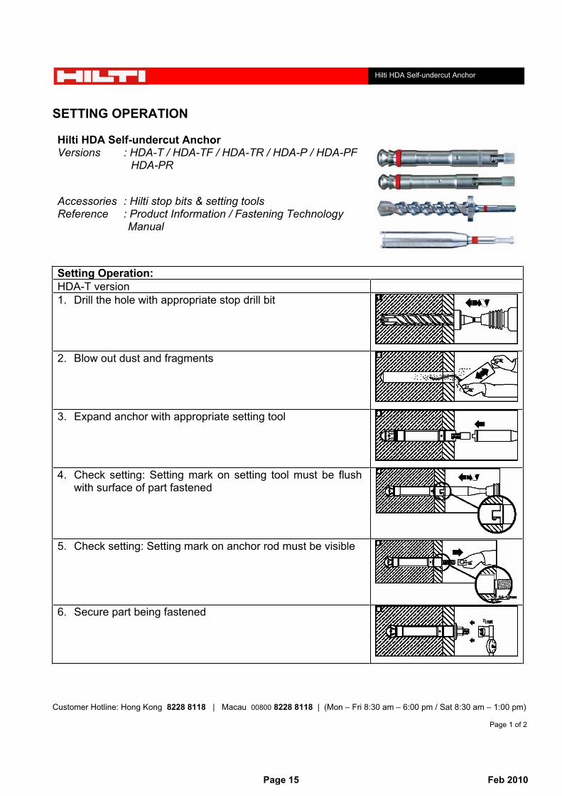
SETTING OPERATION
Hilti HDA Self-undercut Anchor Versions : HDA-T / HDA-TF / HDA-TR / HDA-P / HDA-PF HDA-PR
Accessories : Hilti stop bits & setting tools Reference : Product Information / Fastening Technology Manual
Setting Operation: HDA-T version 1. Drill the hole with appropriate stop drill bit
2. Blow out dust and fragments
3. Expand anchor with appropriate setting tool
4. Check setting: Setting mark on setting tool must be flush with surface of part fastened
5. Check setting: Setting mark on anchor rod must be visible
6. Secure part being fastened
Page 15 Feb 2010

Customer Hotline: Hong Kong 8228 8118 | Macau 00800 8228 8118 | (Mon – Fri 8:30 am – 6:00 pm / Sat 8:30 am – 1:00 pm)
Page 2 of 2
Hilti HDA Self-undercut Anchor
Setting Operation: HDA-P version 1. Drill the hole with appropriate stop drill bit
2. Blow out dust and fragments
7. Expand anchor with appropriate setting tool
8. Check setting: Setting mark on setting tool must be flush with concrete surface
9. Check setting: Setting mark on anchor rod must be visible
10. Secure part being fastened
REMARKS
Size -T / -P ver. TE25 TE35 TE56 TE76 (ATC)M10 HDA TE-C-HDA-ST 20-M10 not allowed TE-Y-HDA-ST 20-M10 not allowed
HDA-R TE-C-HDA-ST 20-M10 TE-C-HDA-ST 20-M10 TE-Y-HDA-ST 20-M10 not allowedHDA-F not allowed TE-C-HDA-ST 20-M10 not allowed not allowed
M12 HDA TE-C-HDA-ST 22-M12 not allowed TE-Y-HDA-ST 22-M12 not allowedHDA-R TE-C-HDA-ST 22-M12 TE-C-HDA-ST 22-M12 TE-Y-HDA-ST 22-M12 not allowedHDA-F not allowed TE-C-HDA-ST 22-M12 not allowed not allowed
M16 HDA not allowed not allowed not allowed TE-Y-HDA-ST 30-M16HDA-R not allowed not allowed not allowed TE-Y-HDA-ST 30-M16HDA-F not allowed not allowed not allowed TE-Y-HDA-ST 30-M16
M20 HDA not allowed not allowed not allowed TE-Y-HDA-ST 37-M20
Page 16 Feb 2010

Summary of Test result of Hilti HDA-T Self-undercut Anchor
Sample Description: [supplied by Hilti (Hong Kong) Ltd.]
Product:
Size: M10 - M20
Material:
Coating: min. 5 microns meter thick of zinc plating
Concrete Description: [supplied and tested by Materialab Ltd & ETS Testconsult Ltd]
Concrete Strength: 30MPa at 26days
Mix Proportion: Grade 30/20
Laboratory Information:
Name of Laboratory: Materialab Ltd (HOKLAS No. 015) & ETS-Testconsult Ltd (HOKLAS No. 022)
Test Method: BS 5080: Part 1: 1993BS 5080: Part 2: 1986
Date Tested: April-02
Test Result:
Result 1 Result 2 Result 3 Result 4 Result 5 Avg.Value
Std.Dev.
Charact.Load
[kN] [kN] [kN] [kN] [kN] [kN] [kN]Tensile 48.50 48.60 47.40 49.60 48.80 48.58 0.79 45.89Shear 86.10 83.96 80.56 91.11 88.25 86.00 4.03 72.26Tensile 79.80 76.10 75.20 72.80 74.20 75.62 2.64 66.62Shear 113.53 136.29 149.75 127.47 117.71 128.95 14.60 79.16Tensile 138.15 137.68 139.54 137.22 134.98 137.51 1.66 131.85Shear 165.54 166.01 164.15 177.15 187.37 172.04 10.02 137.86Tensile 207.10 209.00 210.00 216.40 213.40 211.18 3.71 198.54Shear 238.10 224.50 222.70 220.60 225.00 226.18 6.88 202.71
HDA-T M16
HDA-T M20
HDA-T M10
HDA-T M12
Size Type
HDA-T
Galvanized steel
Page 17 Feb 2010

Page 18 Feb 2010

Page 19 Feb 2010

Page 20 Feb 2010
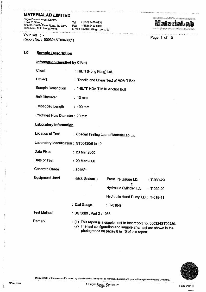
Page 21 Feb 2010

Page 22 Feb 2010

Page 23 Feb 2010

Page 24 Feb 2010

Page 25 Feb 2010

Page 26 Feb 2010

Page 27 Feb 2010

Page 28 Feb 2010

Page 29 Feb 2010
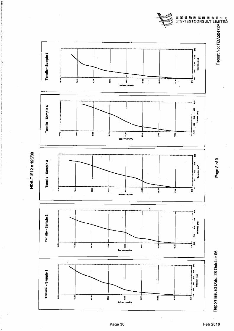
Page 30 Feb 2010

Page 31 Feb 2010

Page 32 Feb 2010

Page 33 Feb 2010

Page 34 Feb 2010

Page 35 Feb 2010

Page 36 Feb 2010

Page 37 Feb 2010

Page 38 Feb 2010

Page 39 Feb 2010

Page 40 Feb 2010

Page 41 Feb 2010

Page 42 Feb 2010

Page 43 Feb 2010

Page 44 Feb 2010

Page 45 Feb 2010

Page 46 Feb 2010

Page 47 Feb 2010

Page 48 Feb 2010
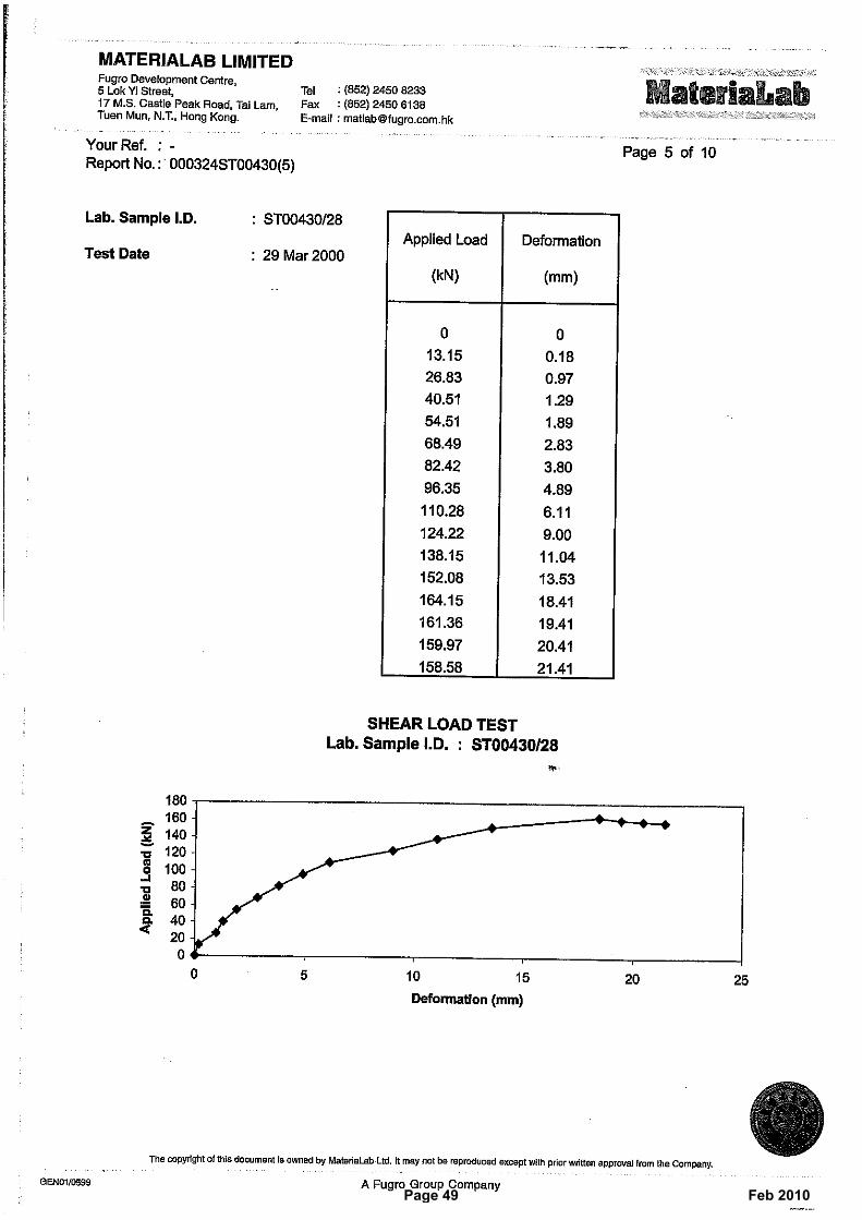
Page 49 Feb 2010

Page 50 Feb 2010
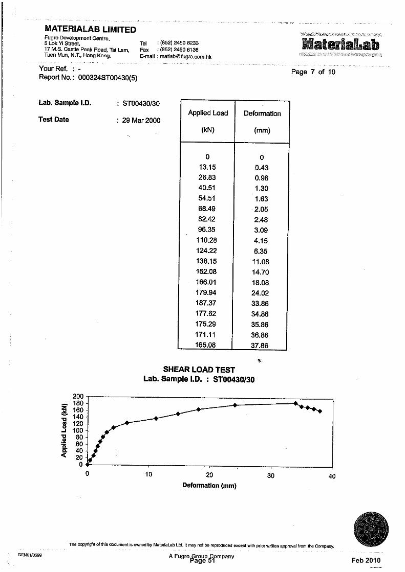
Page 51 Feb 2010

Page 52 Feb 2010

Page 53 Feb 2010

Page 54 Feb 2010

Page 55 Feb 2010

Page 56 Feb 2010

Page 57 Feb 2010

Summary of Test result of Hilti HDA-TR Self-undercut Anchor
Sample Description: [supplied by Hilti (Hong Kong) Ltd.]
Product:
Size: M10 - M16
Material:
Coating: N/A
Concrete Description: [supplied and tested by ETS Testconsult Ltd]
Concrete Strength: 30MPa at 26days
Mix Proportion: Grade 30/20
Laboratory Information:
Name of Laboratory: ETS-Testconsult Ltd (HOKLAS No. 022)
Test Method: BS 5080: Part 1: 1993BS 5080: Part 2: 1986
Date Tested: June-05
Test Result:
Result 1 Result 2 Result 3 Result 4 Result 5 Avg.Value
Std.Dev.
Charact.Load
[kN] [kN] [kN] [kN] [kN] [kN] [kN]Tensile 50.20 49.30 48.50 52.10 48.70 49.76 1.47 44.76Shear 78.10 79.70 75.70 76.00 75.10 76.92 1.92 70.37Tensile 73.00 73.00 72.30 70.80 71.20 72.06 1.02 68.59Shear 98.60 104.00 107.00 103.20 108.00 104.16 3.70 91.55Tensile 134.00 131.50 128.20 134.80 130.50 131.80 2.67 122.69Shear 168.40 181.70 180.20 178.00 177.40 177.14 5.18 159.47
HDA-TR M16
HDA-TR M10
HDA-TR M12
Size Type
HDA-TR
A4-80 stainless steel
Page 58 Feb 2010

Page 59 Feb 2010
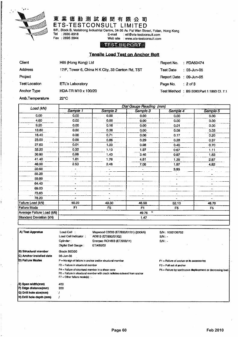
Page 60 Feb 2010
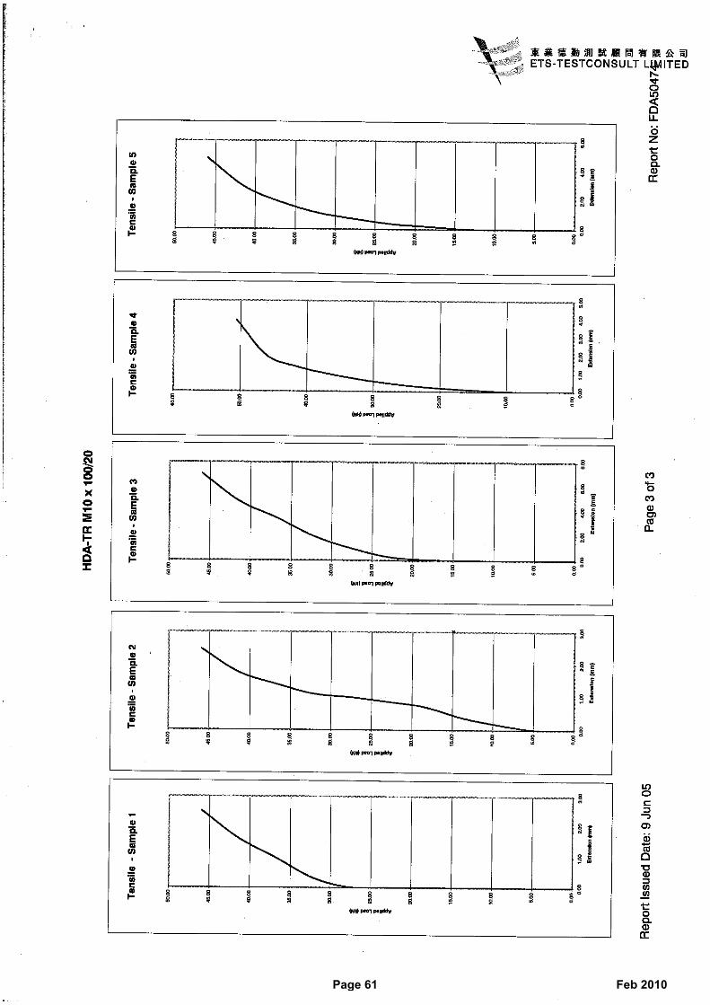
Page 61 Feb 2010

Page 62 Feb 2010

Page 63 Feb 2010

Page 64 Feb 2010

Page 65 Feb 2010

Page 66 Feb 2010

Page 67 Feb 2010

Page 68 Feb 2010

Page 69 Feb 2010

Page 70 Feb 2010

Page 71 Feb 2010

Page 72 Feb 2010
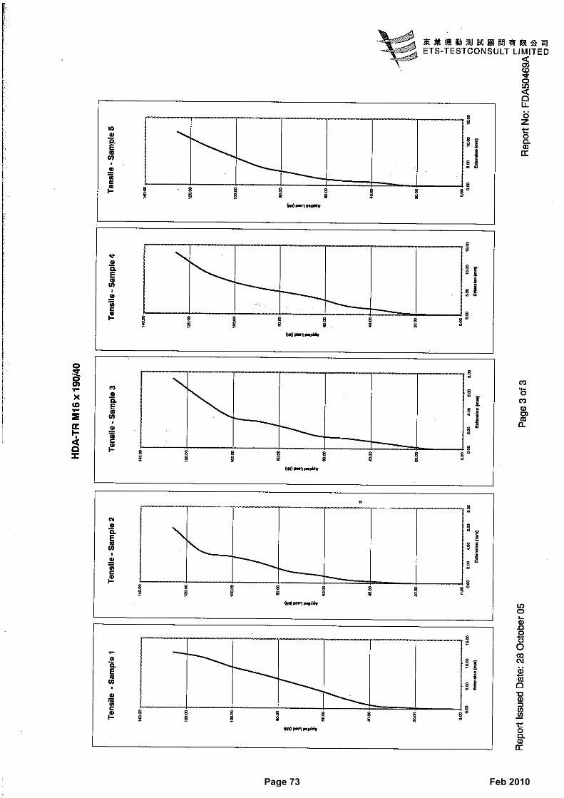
Page 73 Feb 2010

Page 74 Feb 2010

Page 75 Feb 2010

Page 76 Feb 2010

Cen
tre
Sci
entif
ique
et
Tec
hniq
ue d
u B
âtim
ent
4, a
venu
e du
Rec
teur
Poi
ncar
é F
-757
82 P
AR
IS C
edex
16
Tél
. : (
33)
01 4
0 50
28
28
Fax
: (3
3) 0
1 45
25
61 5
1
Aut
oris
é et
notif
ié c
onfo
rmém
ent à
l’art
icle
10
de la
dire
ctiv
e89
/106
/EE
C d
u C
onse
il, d
u21
déc
embr
e 19
88, r
elat
ive
aura
ppro
chem
ent d
es d
ispo
sitio
nslé
gisl
ativ
es, r
égle
men
taire
set
adm
inis
trat
ives
des
Eta
tsm
embr
es c
once
rnan
tle
s pr
odui
ts d
eco
nstr
uctio
n.
ME
MB
RE
DE
L’E
OT
A
Eu
rop
ean
Tec
hn
ical
Ap
pro
val
E
TA
-99/
0009
(E
nglis
h la
ngua
ge tr
ansl
atio
n, th
e or
igin
al v
ersi
on is
in F
renc
h la
ngua
ge)
Nom
com
mer
cial
: T
rad
e n
ame:
HIL
TI H
DA
T
itula
ire :
Ho
lder
of
app
rova
l:
H
ilti A
G, B
usi
nes
s U
nit
An
cho
rs
FL
-949
4 S
CH
AA
N
Pri
nci
pal
ity
of
Lie
chte
nst
ein
Typ
e gé
nériq
ue e
t util
isat
ion
prév
ue d
u pr
odui
t de
cons
truc
tion
:
Che
ville
mét
alliq
ue e
n ac
ier
galv
anis
é, à
ver
roui
llage
de
form
e pa
r au
to
ancr
age,
de
fixat
ion
dans
le b
éton
: di
amèt
res
M10
, M12
, M16
et M
20.
Gen
eric
typ
e an
d u
se o
f co
nst
ruct
ion
pro
du
ct:
S
elf-
cutt
ing
un
der
cut
anch
or,
mad
e o
f g
alva
nis
ed s
teel
, fo
r u
se in
co
ncr
ete:
siz
es M
10, M
12, M
16 a
nd
M20
.
Val
idité
du
:
au :
Val
idit
y fr
om
/ to
:
30
/03/
2004
30
/03/
2009
U
sine
de
fabr
icat
ion
: M
anu
fact
uri
ng
pla
nt:
Hilt
i AG
, usi
ne
1 (p
lan
t 1)
, Pri
nci
pal
ity
of
Lie
chte
nst
ein
Le
pré
sent
Agr
émen
t tec
hniq
ue e
urop
éen
cont
ient
: T
his
Eu
rop
ean
Tec
hn
ical
Ap
pro
val
con
tain
s:
16 p
ages
incl
uant
9 a
nnex
es fa
isan
t par
tie in
tégr
ante
du
docu
men
t.
16 p
ages
incl
ud
ing
9 a
nn
exes
wh
ich
fo
rm a
n in
teg
ral p
art
of
the
do
cum
ent.
Thi
s E
urop
ean
Tec
hnic
al A
ppro
val r
epla
ces
ET
A-9
9/00
09 w
ith v
alid
ity fr
om 0
6.10
.199
9 to
06.
10.2
004
Cet
Agr
émen
t Tec
hniq
ue E
urop
éen
rem
plac
e l’E
TA
-99/
0009
val
ide
du 0
6.10
.199
9 au
06.
10.2
004
Org
anis
atio
n po
ur l’
Agr
émen
t Tec
hniq
ue E
urop
éen
Eur
opea
n O
rgan
isat
ion
for
Tec
hnic
al A
ppro
vals
Pag
e 2
of E
urop
ean
Tec
hnic
al A
ppro
val E
TA
-99/
0009
I L
EG
AL
BA
SE
S A
ND
GE
NE
RA
L C
ON
DIT
ION
S
1.
Thi
s E
urop
ean
Tec
hnic
al
App
rova
l is
is
sued
by
th
e C
entr
e S
cien
tifiq
ue
et
Tec
hniq
ue
du
Bât
imen
t in
acco
rdan
ce w
ith:
− C
ounc
il D
irect
ive
89/1
06/E
EC
of
21
D
ecem
ber
1988
on
th
e ap
prox
imat
ion
of
law
s,
regu
latio
ns
and
adm
inis
trat
ive
prov
isio
ns
of
Mem
ber
Sta
tes
rela
ting
to
cons
truc
tion
prod
ucts
1 , mod
ified
by
the
Cou
ncil
Dire
ctiv
e 93
/68/
EE
C o
f 22
July
199
32 ;
− D
écre
t n°
92-
647
du
8 ju
illet
19
923
conc
erna
nt
l’apt
itude
à
l’usa
ge
des
prod
uits
de
co
nstr
uctio
n;
− C
omm
on
Pro
cedu
ral
Rul
es
for
Req
uest
ing,
P
repa
ring
and
the
Gra
ntin
g of
E
urop
ean
Tec
hnic
al A
ppro
vals
set
out
in th
e A
nnex
of C
omm
issi
on D
ecis
ion
94/2
3/E
C4 ;
− G
uide
line
for
Eur
opea
n T
echn
ical
A
ppro
val
of
« M
etal
A
ncho
rs
for
use
in
Con
cret
e »
ET
AG
001
, edi
tion
1997
, Par
t 1 «
Anc
hors
in g
ener
al »
and
Par
t 3 «
Und
ercu
t anc
hors
».
2.
The
C
entr
e S
cien
tifiq
ue
et
Tec
hniq
ue
du
Bât
imen
t is
au
thor
ised
to
ch
eck
whe
ther
th
e pr
ovis
ions
of
this
Eur
opea
n T
echn
ical
App
rova
l ar
e m
et.
Che
ckin
g m
ay t
ake
plac
e in
the
m
anuf
actu
ring
plan
t (f
or
exam
ple
conc
erni
ng
the
fulfi
lmen
t of
as
sum
ptio
ns
mad
e in
th
is
Eur
opea
n T
echn
ical
App
rova
l with
reg
ard
to m
anuf
actu
ring)
. Nev
erth
eles
s, th
e re
spon
sibi
lity
for
the
conf
orm
ity o
f th
e pr
oduc
ts w
ith th
e E
urop
ean
Tec
hnic
al A
ppro
val a
nd fo
r th
eir
fitne
ss fo
r th
e in
tend
ed u
se r
emai
ns w
ith th
e ho
lder
of t
he E
urop
ean
Tec
hnic
al A
ppro
val.
3.
Thi
s E
urop
ean
Tec
hnic
al A
ppro
val
is n
ot t
o be
tra
nsfe
rred
to
man
ufac
ture
rs o
r ag
ents
of
man
ufac
ture
r ot
her
than
tho
se i
ndic
ated
on
page
1;
or m
anuf
actu
ring
plan
ts o
ther
tha
n th
ose
indi
cate
d on
pag
e 1
of th
is E
urop
ean
Tec
hnic
al A
ppro
val.
4.
Thi
s E
urop
ean
Tec
hnic
al A
ppro
val
may
be
with
draw
n by
the
Cen
tre
Sci
entif
ique
et
Tec
hniq
ue
du B
âtim
ent p
ursu
ant t
o A
rtic
le 5
(1)
of t
he C
ounc
il D
irect
ive
89/1
06/E
EC
.
5.
Rep
rodu
ctio
n of
thi
s E
urop
ean
Tec
hnic
al A
ppro
val
incl
udin
g tr
ansm
issi
on b
y el
ectr
onic
mea
ns
shal
l be
in
full.
How
ever
, pa
rtia
l re
prod
uctio
n ca
n be
mad
e w
ith t
he w
ritte
n co
nsen
t of
the
C
entr
e S
cien
tifiq
ue e
t T
echn
ique
du
Bât
imen
t. In
thi
s ca
se p
artia
l re
prod
uctio
n ha
s to
be
desi
gnat
ed a
s su
ch.
Tex
ts a
nd d
raw
ings
of
adve
rtis
ing
broc
hure
s sh
all n
ot c
ontr
adic
t or
mis
use
the
Eur
opea
n T
echn
ical
App
rova
l.
6.
The
Eur
opea
n T
echn
ical
App
rova
l is
iss
ued
by t
he a
ppro
val
body
in
its o
ffic
ial
lang
uage
. T
his
vers
ion
corr
espo
nds
to t
he v
ersi
on c
ircul
ated
with
in E
OT
A.
Tra
nsla
tions
int
o ot
her
lang
uage
s ha
ve to
be
desi
gnat
ed a
s su
ch.
1 O
ffic
ial J
ourn
al o
f th
e E
urop
ean
Com
mun
itie
s n°
L 4
0, 1
1.2.
1989
, p. 1
2 2
Off
icia
l Jou
rnal
of
the
Eur
opea
n C
omm
unit
ies
n° L
220
, 30.
8.19
93, p
. 1
3 Jo
urna
l off
icie
l de
la R
épub
liqu
e fr
ança
ise
du 1
4 ju
ille
t 199
2 4
Off
icia
l Jou
rnal
of
the
Eur
opea
n C
omm
unit
ies
n° L
17,
20.
1.19
94, p
. 34
Page 77 Feb 2010

Pag
e 3
of E
urop
ean
Tec
hnic
al A
ppro
val E
TA
-99/
0009
II
SP
EC
IFIC
CO
ND
ITIO
NS
OF
TH
E E
UR
OP
EA
N T
EC
HN
ICA
L A
PP
RO
VA
L
1 D
efin
itio
n o
f p
rod
uct
an
d in
ten
ded
use
1.1.
Def
init
ion
of
pro
du
ct
The
HIL
TI
HD
A a
ncho
r in
the
ran
ge o
f M
10 t
o M
20 i
s a
self-
cutti
ng u
nder
cut
anch
or m
ade
of
galv
anis
ed s
teel
. It
is a
vaila
ble
as p
re-s
ettin
g (H
DA
-P v
ersi
on)
and
as t
hrou
gh-f
aste
ning
anc
hor
(HD
A-T
ver
sion
). I
t is
pla
ced
into
a h
ole
drill
ed w
ith a
spe
cial
sto
p dr
ill b
it an
d se
lf-cu
tting
un
derc
ut u
sing
a s
peci
al s
ettin
g to
ol.
The
nut
is
torq
ue t
ight
ened
to
com
plet
e th
e fa
sten
ing
of
the
fixtu
re.
For
the
inst
alle
d an
chor
see
Fig
ures
giv
en in
Ann
exes
1 a
nd 2
.
1.2.
Inte
nd
ed u
se
The
anc
hor
is i
nten
ded
to b
e us
ed f
or a
ncho
rage
s fo
r w
hich
req
uire
men
ts f
or m
echa
nica
l re
sist
ance
and
sta
bilit
y an
d sa
fety
in u
se in
the
sen
se o
f th
e E
ssen
tial R
equi
rem
ents
1 a
nd 4
of
Cou
ncil
Dire
ctiv
e 89
/106
/EE
C s
hall
be f
ulfil
led
and
failu
re o
f an
chor
ages
mad
e w
ith t
hese
pr
oduc
ts w
ould
com
prom
ise
the
stab
ility
of
the
wor
ks,
caus
e ris
k to
hum
an l
ife a
nd/o
r le
ad t
o co
nsid
erab
le e
cono
mic
con
sequ
ence
s. T
he a
ncho
r is
to b
e us
ed o
nly
for
anch
orag
es s
ubje
ct to
st
atic
or
quas
i-sta
tic l
oadi
ng i
n re
info
rced
or
unre
info
rced
nor
mal
wei
ght
conc
rete
of
stre
ngth
cl
asse
s C
20/
25 m
inim
um t
o C
50/6
0 m
axim
um a
ccor
ding
to
EN
V 2
06-1
: 20
00-1
2. I
t m
ay b
e an
chor
ed in
cra
cked
and
non
-cra
cked
con
cret
e.
The
anc
hor
may
onl
y be
use
d in
con
cret
e su
bjec
t to
dry
inte
rnal
con
ditio
ns.
The
pro
visi
ons
mad
e in
thi
s E
urop
ean
Tec
hnic
al A
ppro
val a
re b
ased
on
an a
ssum
ed in
tend
ed
wor
king
life
of
the
anch
or o
f 50
yea
rs.
The
ind
icat
ions
giv
en o
n th
e w
orki
ng l
ife c
anno
t be
in
terp
rete
d as
a g
uara
ntee
giv
en b
y th
e pr
oduc
er,
but
are
to b
e re
gard
ed o
nly
as a
mea
ns f
or
choo
sing
the
rig
ht p
rodu
cts
in r
elat
ion
to t
he e
xpec
ted
econ
omic
ally
rea
sona
ble
wor
king
life
of
the
wor
ks.
2 C
har
acte
rist
ics
of
pro
du
ct a
nd
met
ho
ds
of
veri
fica
tio
n
2.1.
C
har
acte
rist
ics
of
pro
du
ct
The
anc
hor
in t
he r
ange
of
M10
to
M20
cor
resp
onds
to
the
draw
ings
and
pro
visi
ons
give
n in
A
nnex
es 1
to
5. T
he c
hara
cter
istic
mat
eria
l va
lues
, di
men
sion
s an
d to
lera
nces
of
the
anch
or
not
indi
cate
d in
Ann
exes
3 t
o 5
shal
l co
rres
pond
to
the
resp
ectiv
e va
lues
lai
d do
wn
in t
he
tech
nica
l do
cum
enta
tion5
of
this
E
urop
ean
Tec
hnic
al
App
rova
l. T
he
char
acte
ristic
an
chor
va
lues
for
the
des
ign
of a
ncho
rage
s ar
e gi
ven
in A
nnex
es 5
to
7. T
he s
peci
al t
ools
req
uire
d to
us
e th
is a
ncho
r ar
e de
scrib
ed in
Ann
exes
8 to
9.
Eac
h an
chor
is
mar
ked
with
the
man
ufac
ture
r's n
ame,
the
com
mer
cial
nam
e, t
he v
ersi
on,
the
spec
ial
step
ped
drill
bit
nom
inal
dia
met
er,
the
nom
inal
dia
met
er o
f th
e th
read
, th
e ef
fect
ive
embe
dmen
t dep
th a
nd th
e m
axim
um th
ickn
ess
of th
e fix
ture
acc
ordi
ng to
Ann
ex 3
.
5T
he te
chni
cal d
ocum
enta
tion
of th
is E
urop
ean
Tec
hnic
al A
ppro
val i
s de
posi
ted
at th
e C
entr
e S
cien
tifiq
ue
et T
echn
ique
du
Bât
imen
t and
, as
far
as r
elev
ant f
or th
e ta
sks
of th
e ap
prov
ed b
odie
s in
volv
ed in
the
atte
stat
ion
of c
onfo
rmity
pro
cedu
re, i
s ha
nded
ove
r to
the
appr
oved
bod
ies.
Pag
e 4
of E
urop
ean
Tec
hnic
al A
ppro
val E
TA
-99/
0009
On
the
thre
aded
par
t of
the
bol
t, a
smal
l no
n-th
read
ed c
olou
red
ring
mar
king
ide
ntifi
es t
he
com
plet
e ex
pans
ion
of t
he s
leev
e. A
lette
r co
de c
orre
spon
ding
to
the
tota
l len
gth
of t
he b
olt
is
punc
hed
on th
e he
ad o
f the
bol
t.
The
anc
hor
shal
l onl
y be
pac
kage
d an
d su
pplie
d as
a c
ompl
ete
unit.
2.2.
M
eth
od
s o
f ve
rifi
cati
on
The
ass
essm
ent
of f
itnes
s of
the
anc
hor
for
the
inte
nded
use
in r
elat
ion
to t
he r
equi
rem
ents
for
m
echa
nica
l re
sist
ance
an
d st
abili
ty
and
safe
ty
in
use
in
the
sens
e of
th
e E
ssen
tial
Req
uire
men
ts 1
and
4 h
as b
een
mad
e in
acc
orda
nce
with
the
« G
uide
line
for
Eur
opea
n T
echn
ical
App
rova
l of
Met
al A
ncho
rs f
or u
se i
n C
oncr
ete
», P
art
1 «
Anc
hors
in
gene
ral »
and
P
art 3
« U
nder
cut a
ncho
rs »
, on
the
basi
s of
Opt
ion
1.
3 E
valu
atio
n o
f C
on
form
ity
and
CE
mar
kin
g
3.1.
A
ttes
tati
on
of
con
form
ity
syst
em
The
sys
tem
of
atte
stat
ion
of c
onfo
rmity
2 (
i) (r
efer
red
to a
s sy
stem
1)
acco
rdin
g to
Cou
ncil
Dire
ctiv
e 89
/106
/EE
C A
nnex
III l
aid
dow
n by
the
Eur
opea
n C
omm
issi
on p
rovi
des:
a) ta
sks
for
the
man
ufac
ture
r:
1. fa
ctor
y pr
oduc
tion
cont
rol,
2. fu
rthe
r te
stin
g of
sam
ples
take
n at
the
fact
ory
by th
e m
anuf
actu
rer
in a
ccor
danc
e w
ith a
pre
scrib
ed te
st p
lan.
b) ta
sks
for
the
appr
oved
bod
y:
3. in
itial
type
-tes
ting
of th
e pr
oduc
t, 4.
initi
al in
spec
tion
of fa
ctor
y an
d of
fact
ory
prod
uctio
n co
ntro
l, 5.
con
tinuo
us s
urve
illan
ce, a
sses
smen
t and
app
rova
l of f
acto
ry p
rodu
ctio
n co
ntro
l.
3.2.
R
esp
on
sib
iliti
es
3.2.
1. T
asks
of t
he m
anuf
actu
rer,
fact
ory
prod
uctio
n co
ntro
l
The
man
ufac
ture
r ha
s a
fact
ory
prod
uctio
n co
ntro
l sys
tem
in th
e pl
ant a
nd e
xerc
ises
per
man
ent
inte
rnal
con
trol
of
prod
uctio
n. A
ll th
e el
emen
ts,
requ
irem
ents
and
pro
visi
ons
adop
ted
by t
he
man
ufac
ture
r ar
e do
cum
ente
d in
a s
yste
mat
ic m
anne
r in
the
for
m o
f w
ritte
n po
licie
s an
d pr
oced
ures
. T
his
prod
uctio
n co
ntro
l sy
stem
ens
ures
tha
t th
e pr
oduc
t is
in
conf
orm
ity w
ith t
he
Eur
opea
n T
echn
ical
App
rova
l.
The
man
ufac
ture
r sh
all o
nly
use
raw
mat
eria
ls s
uppl
ied
with
the
rel
evan
t in
spec
tion
docu
men
ts
as l
aid
dow
n in
the
pre
scrib
ed t
est
plan
6 . T
he i
ncom
ing
raw
mat
eria
ls s
hall
be s
ubje
ct t
o co
ntro
ls a
nd t
ests
by
the
man
ufac
ture
r be
fore
acc
epta
nce.
Che
ck o
f in
com
ing
mat
eria
ls s
uch
as n
uts,
was
hers
, w
ire f
or b
olts
and
sle
eves
sha
ll in
clud
e co
ntro
l of
the
ins
pect
ion
docu
men
ts
pres
ente
d by
su
pplie
rs
(com
paris
on
with
no
min
al
valu
es)
by
verif
ying
di
men
sion
an
d de
term
inin
g m
ater
ial p
rope
rtie
s, e
.g. t
ensi
le s
tren
gth,
har
dnes
s, s
urfa
ce fi
nish
.
6 T
he p
resc
ribed
test
pla
n ha
s be
en d
epos
ited
at th
e C
entr
e S
cien
tifiq
ue e
t Tec
hniq
ue d
u B
âtim
ent a
nd is
on
ly m
ade
avai
labl
e to
the
appr
oved
bod
ies
invo
lved
in th
e co
nfor
mity
atte
stat
ion
proc
edur
e.
Page 78 Feb 2010

Pag
e 5
of E
urop
ean
Tec
hnic
al A
ppro
val E
TA
-99/
0009
The
man
ufac
ture
d co
mpo
nent
s of
the
anch
or s
hall
be s
ubje
cted
to th
e fo
llow
ing
test
s:
− D
imen
sion
s of
com
pone
nt p
arts
:
bolt
(dia
met
ers,
leng
ths,
thre
ad a
nd r
ing
mar
king
, geo
met
ry o
f the
con
e);
sl
eeve
(le
ngth
s, in
tern
al a
nd e
xter
nal d
iam
eter
s, g
eom
etry
of t
he e
xpan
sion
par
t, cu
tting
edg
e);
pl
astic
rin
g (d
iam
eter
s, th
ickn
ess)
;
hexa
gona
l nut
(pr
oper
run
ning
, wre
nch
size
acr
oss
flats
);
w
ashe
r (d
iam
eter
s, th
ickn
ess)
. −
Mat
eria
l pr
oper
ties:
bol
t (u
ltim
ate
tens
ile s
tren
gth)
, sl
eeve
(ul
timat
e te
nsile
str
engt
h),
plas
tic
ring
(mat
eria
l com
posi
tion)
, hex
agon
al n
ut (
proo
f loa
d), w
ashe
r (h
ardn
ess)
. −
Thi
ckne
ss o
f the
gal
vani
sed
trea
tmen
t of t
he e
lem
ents
. −
Vis
ual c
ontr
ol o
f cor
rect
ass
embl
y an
d of
com
plet
enes
s of
the
anch
or.
The
fre
quen
cy o
f co
ntro
ls a
nd t
ests
con
duct
ed d
urin
g pr
oduc
tion
and
on t
he a
ssem
bled
anc
hor
is la
id d
own
in t
he p
resc
ribed
tes
t pl
an t
akin
g ac
coun
t of
the
aut
omat
ed m
anuf
actu
ring
proc
ess
of th
e an
chor
.
The
res
ults
of
fact
ory
prod
uctio
n co
ntro
l ar
e re
cord
ed a
nd e
valu
ated
. T
he r
ecor
ds i
nclu
de a
t le
ast t
he fo
llow
ing
info
rmat
ion:
− de
sign
atio
n of
the
prod
uct,
basi
c m
ater
ial a
nd c
ompo
nent
s;
− ty
pe o
f con
trol
or
test
ing;
−
date
of
man
ufac
ture
of
the
prod
uct
and
date
of
test
ing
of t
he p
rodu
ct o
r ba
sic
mat
eria
l and
co
mpo
nent
s;
− re
sult
of c
ontr
ol a
nd te
stin
g an
d, if
app
ropr
iate
, com
paris
on w
ith r
equi
rem
ents
; −
sign
atur
e of
per
son
resp
onsi
ble
for
fact
ory
prod
uctio
n co
ntro
l.
The
rec
ords
sha
ll be
pre
sent
ed t
o th
e in
spec
tion
body
dur
ing
the
cont
inuo
us s
urve
illan
ce.
On
requ
est,
they
sha
ll be
pre
sent
ed to
the
Cen
tre
Sci
entif
ique
et T
echn
ique
du
Bât
imen
t.
Det
ails
of
the
exte
nt,
natu
re a
nd f
requ
ency
of
test
ing
and
cont
rols
to
be p
erfo
rmed
with
in t
he
fact
ory
prod
uctio
n co
ntro
l sh
all
corr
espo
nd t
o th
e pr
escr
ibed
tes
t pl
an w
hich
is
part
of
the
tech
nica
l doc
umen
tatio
n of
this
Eur
opea
n T
echn
ical
App
rova
l.
3.2.
2. T
asks
of a
ppro
ved
bodi
es
3.2.
2.1.
Initi
al ty
pe-t
estin
g of
the
prod
uct
For
ini
tial
type
-tes
ting
the
resu
lts o
f th
e te
sts
perf
orm
ed a
s pa
rt o
f th
e as
sess
men
t fo
r th
e E
urop
ean
Tec
hnic
al A
ppro
val s
hall
be u
sed
unle
ss t
here
are
cha
nges
in t
he p
rodu
ctio
n lin
e or
pl
ant.
In s
uch
case
s th
e ne
cess
ary
initi
al t
ype-
test
ing
has
to b
e ag
reed
bet
wee
n th
e C
entr
e S
cien
tifiq
ue e
t Tec
hniq
ue d
u B
âtim
ent a
nd th
e ap
prov
ed b
odie
s in
volv
ed.
3.2.
2.2.
Initi
al in
spec
tion
of fa
ctor
y an
d of
fact
ory
prod
uctio
n co
ntro
l
The
app
rove
d bo
dy s
hall
asce
rtai
n th
at,
in a
ccor
danc
e w
ith t
he p
resc
ribed
tes
t pl
an,
the
fact
ory
and
the
fact
ory
prod
uctio
n co
ntro
l are
sui
tabl
e to
ens
ure
cont
inuo
us a
nd o
rder
ly m
anuf
actu
ring
of t
he a
ncho
r ac
cord
ing
to t
he s
peci
ficat
ions
men
tione
d in
2.1
. as
wel
l as
to t
he A
nnex
es t
o th
e E
urop
ean
Tec
hnic
al A
ppro
val.
3.2.
2.3.
Con
tinuo
us s
urve
illan
ce
The
app
rove
d bo
dy s
hall
visi
t th
e fa
ctor
y at
leas
t on
ce a
yea
r fo
r re
gula
r in
spec
tion.
It h
as to
be
verif
ied
that
th
e sy
stem
of
fa
ctor
y pr
oduc
tion
cont
rol
and
the
spec
ified
au
tom
ated
m
anuf
actu
ring
proc
ess
are
mai
ntai
ned
taki
ng a
ccou
nt o
f the
pre
scrib
ed te
st p
lan.
Pag
e 6
of E
urop
ean
Tec
hnic
al A
ppro
val E
TA
-99/
0009
Con
tinuo
us s
urve
illan
ce a
nd a
sses
smen
t of
fac
tory
pro
duct
ion
cont
rol
have
to
be p
erfo
rmed
ac
cord
ing
to th
e pr
escr
ibed
test
pla
n.
The
res
ults
of
prod
uct
cert
ifica
tion
and
cont
inuo
us s
urve
illan
ce s
hall
be m
ade
avai
labl
e on
de
man
d by
the
cer
tific
atio
n bo
dy o
r in
spec
tion
body
, re
spec
tivel
y, t
o th
e C
entr
e S
cien
tifiq
ue e
t T
echn
ique
du
Bât
imen
t. In
cas
es w
here
the
pro
visi
ons
of t
he E
urop
ean
Tec
hnic
al A
ppro
val a
nd
the
pres
crib
ed te
st p
lan
are
no lo
nger
fulfi
lled
the
conf
orm
ity c
ertif
icat
e sh
all b
e w
ithdr
awn.
3.3.
C
E-M
arki
ng
The
CE
mar
king
sha
ll be
aff
ixed
on
each
pac
kagi
ng o
f an
chor
s. T
he s
ymbo
l «
CE
» s
hall
be
acco
mpa
nied
by
the
follo
win
g in
form
atio
n:
− id
entif
icat
ion
num
ber
of th
e ce
rtifi
catio
n bo
dy;
− na
me
or id
entif
ying
mar
k of
the
prod
ucer
and
man
ufac
turin
g pl
ant;
− th
e la
st tw
o di
gits
of t
he y
ear
in w
hich
the
CE
-mar
king
was
aff
ixed
; −
num
ber
of th
e E
C c
ertif
icat
e of
con
form
ity;
− nu
mbe
r of
the
Eur
opea
n T
echn
ical
App
rova
l; −
use
cate
gory
(E
TA
G 0
01-1
Opt
ion1
);
− si
ze.
4 A
ssu
mp
tio
ns
un
der
wh
ich
th
e fi
tnes
s o
f th
e p
rod
uct
fo
r th
e in
ten
ded
use
was
fa
vou
rab
ly a
sses
sed
4.1.
M
anu
fact
uri
ng
The
anc
hor
is m
anuf
actu
red
in a
ccor
danc
e w
ith t
he p
rovi
sion
s of
the
Eur
opea
n T
echn
ical
A
ppro
val
usin
g th
e au
tom
ated
man
ufac
turin
g pr
oces
s as
ide
ntifi
ed d
urin
g in
spec
tion
of t
he
plan
t by
the
Cen
tre
Sci
entif
ique
et
Tec
hniq
ue d
u B
âtim
ent
and
the
appr
oved
bod
y an
d la
id
dow
n in
the
tech
nica
l doc
umen
tatio
n.
4.2.
In
stal
lati
on
4.2.
1. D
esig
n of
anc
hora
ges
The
fitn
ess
of th
e an
chor
s fo
r th
e in
tend
ed u
se is
giv
en u
nder
the
follo
win
g co
nditi
ons:
The
anc
hora
ges
are
desi
gned
in
acco
rdan
ce w
ith t
he «
Gui
delin
e fo
r E
urop
ean
Tec
hnic
al
App
rova
l of
Met
al A
ncho
rs f
or U
se i
n C
oncr
ete
», A
nnex
C,
Met
hod
A,
for
unde
rcut
anc
hors
un
der
the
resp
onsi
bilit
y of
an
en
gine
er
expe
rienc
ed
in
anch
orag
es
and
conc
rete
w
ork.
F
or c
oncr
ete
cone
fai
lure
, th
e in
itial
val
ue o
f th
e ch
arac
teris
tic r
esis
tanc
e of
an
HD
A a
ncho
r
plac
ed in
cra
cked
con
cret
e is
obt
aine
d by
: 5,1
,0
,.
.3,8
efcu
beck
cR
kh
fN
= in
stea
d of
equ
atio
n (5
.2a)
in A
nnex
C, §
5.2.
2.4.
Ver
ifiab
le c
alcu
latio
n no
tes
and
draw
ings
are
pre
pare
d ta
king
acc
ount
of
the
load
s to
be
anch
ored
.
The
pos
ition
of
the
anch
or i
s in
dica
ted
on t
he d
esig
n dr
awin
gs (
e.g.
pos
ition
of
the
anch
or
rela
tive
to r
einf
orce
men
t or
to s
uppo
rt, e
tc.)
.
Page 79 Feb 2010

Pag
e 7
of E
urop
ean
Tec
hnic
al A
ppro
val E
TA
-99/
0009
4.2.
2. In
stal
latio
n of
anc
hors
The
fitn
ess
for
use
of th
e an
chor
can
onl
y be
ass
umed
if th
e an
chor
is in
stal
led
as fo
llow
s:
− an
chor
inst
alla
tion
carr
ied
out
by a
ppro
pria
tely
qua
lifie
d pe
rson
nel a
nd u
nder
the
supe
rvis
ion
of th
e pe
rson
res
pons
ible
for
tech
nica
l mat
ters
on
the
site
; −
use
of t
he a
ncho
r on
ly a
s su
pplie
d by
the
man
ufac
ture
r w
ithou
t ex
chan
ging
the
com
pone
nts
of a
n an
chor
; −
anch
or
inst
alla
tion
in
acco
rdan
ce
with
th
e m
anuf
actu
rer’s
sp
ecifi
catio
ns
and
draw
ings
pr
epar
ed fo
r th
at p
urpo
se a
nd u
sing
the
appr
opria
te s
peci
al to
ols;
−
thic
knes
s of
the
fix
ture
cor
resp
ondi
ng t
o th
e ra
nge
of r
equi
red
thic
knes
s va
lues
for
the
typ
e of
anc
hor;
−
chec
ks b
efor
e pl
acin
g th
e an
chor
to
ensu
re t
hat
the
stre
ngth
cla
ss o
f th
e co
ncre
te in
whi
ch
the
anch
or is
to
be p
lace
d is
in t
he r
ange
giv
en a
nd is
not
low
er t
han
that
of
the
conc
rete
to
whi
ch th
e ch
arac
teris
tic lo
ads
appl
y;
− ch
eck
of c
oncr
ete
bein
g w
ell c
ompa
cted
, e.g
. with
out s
igni
fican
t voi
ds;
− cl
earin
g th
e ho
le o
f dril
ling
dust
; −
anch
or i
nsta
llatio
n en
surin
g th
e sp
ecifi
ed e
mbe
dmen
t de
pth
usin
g th
e sp
ecia
l req
uire
d st
op
drill
bit.
−
anch
or i
nsta
llatio
n en
surin
g co
mpl
ete
expa
nsio
n of
the
sle
eve
usin
g th
e sp
ecia
l re
quire
d se
tting
too
l, th
at i
s th
e ap
prop
riate
dep
th r
ed r
ing
mar
king
of
the
setti
ng t
ool
flush
with
the
co
ncre
te s
urfa
ce (
pre-
setti
ng)
resp
ectin
g w
ith t
he f
ixtu
re s
urfa
ce (
thro
ugh-
fast
enin
g),
then
ch
ecki
ng t
he n
on-t
hrea
ded
colo
ured
rin
g m
arki
ng o
n th
e bo
lt is
vis
ible
abo
ve t
he t
op e
dge
of
the
slee
ve;
− ke
epin
g of
the
edge
dis
tanc
e an
d sp
acin
g to
the
spec
ified
val
ues
with
out m
inus
tole
ranc
es;
− po
sitio
ning
of t
he d
rill h
oles
with
out d
amag
ing
the
rein
forc
emen
t; −
in c
ase
of a
bort
ed h
ole:
new
dril
ling
at a
min
imum
dis
tanc
e aw
ay o
f tw
ice
the
dept
h of
the
ab
orte
d ho
le o
r sm
alle
r di
stan
ce if
the
abor
ted
drill
hol
e is
fill
ed w
ith h
igh
stre
ngth
mor
tar
and
if un
der
shea
r or
obl
ique
ten
sion
loa
d it
is n
ot t
o th
e an
chor
in
the
dire
ctio
n of
loa
d ap
plic
atio
n;
− ap
plic
atio
n of
the
torq
ue m
omen
t giv
en in
Ann
ex 5
usi
ng a
cal
ibra
ted
torq
ue w
renc
h.
4.2.
3. R
espo
nsib
ility
of t
he m
anuf
actu
rer
It is
the
man
ufac
ture
r’s r
espo
nsib
ility
to
ensu
re t
hat
the
info
rmat
ion
on t
he s
peci
fic c
ondi
tions
ac
cord
ing
to 1
and
2 in
clud
ing
Ann
exes
ref
erre
d to
in 4
.2.1
. and
4.2
.2. i
s gi
ven
to th
ose
who
are
co
ncer
ned.
Thi
s in
form
atio
n m
ay b
e m
ade
by r
epro
duct
ion
of t
he r
espe
ctiv
e pa
rts
of t
he
Eur
opea
n T
echn
ical
App
rova
l. In
add
ition
all
inst
alla
tion
data
sha
ll be
sho
wn
clea
rly o
n th
e pa
ckag
e an
d/or
on
an e
nclo
sed
inst
ruct
ion
shee
t, pr
efer
ably
usi
ng il
lust
ratio
n(s)
.
The
min
imum
dat
a re
quire
d ar
e:
− dr
ill b
it di
amet
er,
− th
read
dia
met
er,
− m
axim
um th
ickn
ess
of th
e fix
ture
, −
requ
ired
inst
alla
tion
and
hole
dep
th,
− re
quire
d to
rque
mom
ent,
− in
form
atio
n on
the
inst
alla
tion
proc
edur
e, in
clud
ing
clea
ning
of
the
hole
, pre
fera
bly
by m
eans
of
an
illus
trat
ion,
−
refe
renc
e to
any
spe
cial
inst
alla
tion
equi
pmen
t nee
ded,
−
iden
tific
atio
n of
the
man
ufac
turin
g ba
tch.
All
data
sha
ll be
pre
sent
ed in
a c
lear
and
exp
licit
form
.
The
ori
gina
l Fre
nch
vers
ion
is s
igne
d by
Le
Dir
ecte
ur T
echn
ique
J.
-D. M
ER
LE
T
Pag
e 8
of E
urop
ean
Tec
hnic
al A
ppro
val E
TA
-99/
0009
H
ilti D
esig
n A
nch
or
HD
A-P
A
nn
ex 1
of
Eur
opea
n
Pro
du
ct a
nd
inte
nd
ed u
se
T
echn
ical
App
rova
l
ET
A-9
9/00
09
Pre
-set
ting
anch
or H
DA
-P (
Pre
posi
tioni
ng)
Con
ebo
ltR
ing
Sle
eve
Bol
t
Gro
ove
rota
ted
by90
°
Cap
Wa s
her
Hex
agon
nut
Pre
-set
ting
anch
or H
DA
-P (
Pre
posi
tioni
ng) H
DA
-P ~
3mm
Mar
king
(e
xpan
sion
con
trol
)
Fix
ture
thic
knes
sE
ffect
ive
anch
orag
e de
pth
Hol
e de
pth
Page 80 Feb 2010

Pag
e 9
of E
urop
ean
Tec
hnic
al A
ppro
val E
TA
-99/
0009
H
ilti D
esig
n A
nch
or
HD
A-T
A
nn
ex 2
of
Eur
opea
n
Pro
du
ct a
nd
inte
nd
ed u
se
T
echn
ical
App
rova
l
ET
A-9
9/00
09
Thr
ough
-fas
teni
ng a
ncho
r H
DA
-T (
Pos
tpos
ition
ing)
Con
e bo
ltR
ing
Sle
eve
Bol
t
Gro
ove
rota
ted
by 9
0°
Cap
Was
her
Hex
agon
n
ut
Thr
ough
-fas
teni
ng a
ncho
r H
DA
-T (
Pos
tpos
ition
ing)
HD
A- T T
~3m
mM
arki
ng(e
xpan
sion
cont
rol)
Effe
ctiv
ean
chor
age
dept
h
Hol
ede
pth
Fix
ture
thic
knes
s
Pag
e 10
of E
urop
ean
Tec
hnic
al A
ppro
val E
TA
-99/
0009
H
ilti d
esig
n a
nch
or
HD
A
An
nex
3
of E
urop
ean
D
imen
sio
ns
of
anch
or
T
echn
ical
App
rova
l
ET
A-9
9/00
09
Pre
-set
ting
anch
or H
DA
-P (
Pre
posi
tioni
ng) d S
1d S
2d S
3d B
dC
38
21
45
67
Gro
ove
rota
ted
by
90°
SW
Mar
king
:H
ilti H
DA
-P M
... h
/t
effix
Sl
Bl
Thr
ough
-fas
teni
ng a
ncho
r H
DA
-T (
Pos
tpos
ition
ing)
d S1
d S2
d S3
d B
dC
38
24
57
Gro
ove
rota
ted
by
90°
SW
Sl
Bl
6
Mar
king
:H
ilti H
DA
-T M
... h
/t
effix
Hilt
i HD
A-P
do
M..
h ef/t
fix m
ax
(e.g
.: H
ilti H
DA
-P 3
0-M
16x1
90/4
0)
Hilt
i HD
A-T
do
M..
h ef/t
fix m
ax
(e.g
.: H
ilti H
DA
-T 3
0-M
16x1
90/4
0)
Page 81 Feb 2010

Pag
e 11
of E
urop
ean
Tec
hnic
al A
ppro
val E
TA
-99/
0009
H
ilti d
esig
n a
nch
or
HD
A
An
nex
4
Mat
eria
ls,
of
Eur
opea
n
Dim
ensi
on
s o
f an
cho
r
Tec
hnic
al A
ppro
val
E
TA
-99/
0009
Tab
le 1
: M
ater
ials
Par
t D
esig
natio
n H
DA
-P /
HD
A-T
(ga
lvan
ized
≥5μ
m)
1 S
leev
e M
achi
ned
stee
l with
bra
zed
tung
sten
car
bide
tips
2
Bol
t M
10 –
M16
:Col
d fo
rmed
ste
el, g
rade
8.8
M
20 :
Con
e m
achi
ned,
rod
gra
de 8
.8
3 C
oatin
g of
bol
t and
sl
eeve
G
alva
nize
d 5-
25μm
, DIN
509
61
4 H
exag
on n
ut
M10
– M
16 :C
lass
8, h
=1*
d (D
IN 9
34, i
n fu
ture
EN
240
32),
gal
vani
zed
M20
: C
lass
8, E
N 2
4032
, gal
vani
zed
5 W
ashe
r M
10 –
M16
: S
prin
g w
ashe
r D
IN 6
796
(exc
ept s
urfa
ce s
truc
ture
), C
60,
D
acro
met
coa
ting
M20
: w
ashe
r D
IN 6
340,
gal
vani
zed
6 C
uttin
g ed
ges
Tun
gste
n ca
rbid
e 7
Rin
g P
last
ic r
ing
8 C
ap
Pla
stic
cap
Tab
le 2
: D
imen
sion
s
Anc
hor
type
t fi
x1)
[mm
] l B
[mm
]Le
ngth
code
le
tter
l S[m
m]
SW
d S
1
[mm
] d S
2
[mm
] d S
3
[mm
] d C
[mm
] d B
[mm
]
HD
A-P
20-
M10
*100
/20
20
150
I 10
0 17
19
16
.8
18.5
19
.5
10
HD
A-T
20-
M10
*100
/20
20
150
I 12
0 17
19
16
.8
18.5
19
.5
10
HD
A-P
22-
M12
*125
/30
30
190
L 12
5 19
21
18
.8
20.5
21
.4
12
HD
A-P
22-
M12
*125
/50
50
210
N
125
19
21
18.8
20
.5
21.4
12
H
DA
-T 2
2-M
12*1
25/3
0 30
19
0 L
155
19
21
18.8
20
.5
21.4
12
H
DA
-T 2
2-M
12*1
25/5
0 50
21
0 N
17
5 19
21
18
.8
20.5
21
.4
12
HD
A-P
30-
M16
*190
/40
40
275
R
190
24
29
26
29
29
16
HD
A-P
30-
M16
*190
/60
60
295
S
190
24
29
26
29
29
16
HD
A-T
30-
M16
*190
/40
40
275
R
230
24
29
26
29
29
16
HD
A-T
30-
M16
*190
/60
60
295
S
250
24
29
26
29
29
16
HD
A-P
37-
M20
*250
/50
50
360
V
250
30
35
32
35
36
20
HD
A-P
37-
M20
*250
/100
10
0 41
0 X
25
0 30
35
32
35
36
20
H
DA
-T 3
7-M
20*2
50/5
0 50
36
0 V
30
0 30
35
32
35
36
20
H
DA
-T 3
7-M
20*2
50/1
00
100
410
X
350
30
35
32
35
36
20
1)
max
imum
fast
enab
le th
ickn
ess
Pag
e 12
of E
urop
ean
Tec
hnic
al A
ppro
val E
TA
-99/
0009
H
ilti d
esig
n a
nch
or
HD
A
An
nex
5
of E
urop
ean
In
stal
lati
on
dat
a
T
echn
ical
App
rova
l
ET
A-9
9/00
09
Pre
-set
ting
anch
or
Thr
ough
-fas
teni
ng a
ncho
r H
DA
-P (
Pre
posi
tioni
ng)
HD
A-T
(P
ostp
ositi
onin
g)
df
h1
hm
in
he
f
fixtdf
h1
h
he
f
fixt
df
h 1
h min
h ef
Mar
king
t fix
Tab
le 3
: C
hara
cter
istic
val
ues
of a
ncho
rs a
nd in
stal
latio
n
Anc
hor
type
H
DA
M10
H
DA
M12
H
DA
M16
H
DA
M20
Pre
-set
ting/
Thr
ough
-set
ting
PT
PT
PT
PT
Nom
inal
dia
met
er o
f dr
ill b
it d 0
[mm
]20
20
22
22
30
30
37
37
Cut
ting
diam
eter
of
drill
bit
d cut
≤ [m
m]
20,5
520
,55
22,5
522
,55
30,5
530
,55
37,7
037
,70
Dep
th o
f dril
l hol
e h 1
≥ [m
m]
107
107
134,
513
4,5
203
203
266
266
Dia
met
er o
f cl
eara
nce
hole
in th
e fix
ture
d f
[mm
]12
21
14
23
18
32
22
40
Min
imum
fixt
ure
thic
knes
s
Min
. tfix
0 10
0
10
0 15
0
20
Tor
que
mom
ent
Tin
st [N
m]
50
50
80
80
120
120
300
300
Tab
le 4
: M
inim
um th
ickn
ess
of c
oncr
ete
mem
ber,
min
imum
spa
cing
and
min
imum
edg
e di
stan
ces
of a
ncho
rs
HD
A-P
/ H
DA
-T
M10
M12
M16
M20
Min
imum
thic
knes
s of
con
cret
e m
embe
r h m
in
[mm
]17
0 19
0 27
0 35
0
Cra
cked
co
ncr
ete
Min
imum
spa
cing
1)
s min
[m
m]
100
125
190
250
Min
imum
edg
e di
stan
ce 2)
c m
in
[mm
]80
10
0 15
0 20
0
No
n-c
rack
ed c
on
cret
e
Min
imum
spa
cing
1)
s min
[m
m]
100
125
190
250
Min
imum
edg
e di
stan
ce 2)
c m
in
[mm
]80
10
0 15
0 20
0 1)
rat
io s
min
/ h
ef=
1.
0 2)
rat
io c
min
/ h
ef=
0.
8
Page 82 Feb 2010

Pag
e 13
of E
urop
ean
Tec
hnic
al A
ppro
val E
TA
-99/
0009
H
ilti d
esig
n a
nch
or
HD
A
An
nex
6
D
esig
n m
eth
od
A, c
har
acte
rist
ic v
alu
es o
f
of E
urop
ean
res
ista
nce
to
ten
sio
n lo
ads;
dis
pla
cem
ents
Tec
hnic
al A
ppro
val
ET
A-9
9/00
09
Tab
le 5
: C
hara
cter
istic
val
ues
of r
esis
tanc
e to
tens
ion
load
s of
des
ign
m
etho
d A
HD
A-P
/ H
DA
-T
M10
M12
M16
M20
Ste
el f
ailu
re
Cha
ract
eris
tic r
esis
tanc
e N
Rk,
s
[kN
]46
67
12
6 19
2
Par
tial s
afet
y fa
ctor
γ M
s1,
50
Pu
ll-o
ut
failu
re*
Cha
ract
eris
tic r
esis
tanc
e in
cr
acke
d co
ncre
te o
nly
NR
k,p
[kN
]C
20/2
525
35
75
95
Par
tial s
afet
y fa
ctor
in
γ 21,
0
crac
ked
conc
rete
onl
y
γ Mp
1,80
Incr
easi
ng fa
ctor
s
C
30/3
71,
22
for
NR
k,p
ψc
C40
/50
1,41
for
crac
ked
conc
rete
onl
y
C50
/60
1,55
Co
ncr
ete
con
e fa
ilure
** a
nd
sp
litti
ng
fai
lure
Effe
ctiv
e an
chor
age
dept
h h e
f [m
m]
100
125
190
250
Par
tial s
afet
y fa
ctor
in c
rack
ed
γ 21,
0
and
non
crac
ked
conc
rete
γ M
c1,
80
Spa
cing
s c
r,N
[mm
]30
0 37
5 57
0 75
0
Edg
e di
stan
ce
c cr,
N
[mm
]15
0 19
0 28
5 37
5
Spa
cing
s c
r,sp
[m
m]
300
375
570
750
Edg
e di
stan
ce
c cr,
sp
[mm
]15
0 19
0 28
5 37
5
* T
he p
ull-o
ut fa
ilure
mod
e is
not
dec
isiv
e in
non
-cra
cked
con
cret
e; it
doe
s no
t hav
e to
be
calc
ulat
ed b
y th
e de
sign
er.
**
For
con
cret
e co
ne fa
ilure
, the
initi
al v
alue
of t
he c
hara
cter
istic
res
ista
nce
of a
n H
DA
anc
hor
plac
ed in
crac
ked
conc
rete
is o
btai
ned
by:
5,1,
0,
..
3,8ef
cube
ckc
Rk
hf
N=
inst
ead
of e
quat
ion
(5.2
a) in
ET
AG
001
Ann
ex C
, § 5
.2.2
.4.
Tab
le 6
: D
ispl
acem
ents
und
er te
nsio
n lo
ads
HD
A-P
/ H
DA
-T
M10
M12
M16
M20
Ten
sion
load
in C
20/2
5 to
C50
/60
crac
ked
conc
rete
[k
N]
9,9
13,9
29
,7
37,7
Dis
plac
emen
t δ N
0[m
m]
0,1
0,7
2,1
2,1
δ N∞
[mm
]1,
3 1,
3 2,
1 2,
1
Ten
sion
load
in C
20/2
5 to
C50
/60
non-
crac
ked
conc
rete
[k
N]
21,9
31
,9
60,0
91
,0
Dis
plac
emen
t δ N
0[m
m]
0,4
0,8
1,7
2,4
δ N∞
[mm
]1,
3 1,
3 1,
7 2,
4
Pag
e 14
of E
urop
ean
Tec
hnic
al A
ppro
val E
TA
-99/
0009
H
ilti d
esig
n a
nch
or
HD
A
An
nex
7
D
esig
n m
eth
od
A, c
har
acte
rist
ic v
alu
es o
f
of E
urop
ean
res
ista
nce
to
sh
ear
load
s;
T
echn
ical
App
rova
l
E
TA
-99/
0009
Tabl
e 7:
Cha
ract
eris
tic v
alue
s of
resi
stan
ce to
she
ar lo
ads
of d
esig
n m
etho
d A
HD
A-P
M
10M
12M
16M
20
Ste
el f
ailu
re w
ith
ou
t le
ver
arm
Cha
ract
eris
tic r
esis
tanc
e V
Rk,
s [k
N]
22
30
62
92
Par
tial s
afet
y fa
ctor
γ M
s1,
25
Ste
el f
ailu
re w
ith
leve
r ar
m
Cha
ract
eris
tic r
esis
tanc
e M
Rk,
s [N
m]
60
105
266
519
Par
tial s
afet
y fa
ctor
γ M
s1,
25
HD
A-T
M
10M
12M
16M
20
Ste
el f
ailu
re w
ith
ou
t le
ver
arm
C
hara
cter
istic
re
sist
ance
fo
rt fi
x
[mm
]10
≤<
15
15≤
≤20
10≤
<15
15≤
≤50
15≤
<20
20≤
<25
25≤
<30
30≤
≤60
20≤
<35
35≤
<50
≥50
<10
0
V
Rk,
s [k
N]
65
70
80
100
140
155
170
190
205
235
250
Par
tial s
afet
y fa
ctor
γ Ms
1,50
Ste
el f
ailu
re w
ith
leve
r ar
mC
hara
cter
istic
resi
stan
ce
MR
k,s
[Nm
]60
10
5 26
6 51
9
Par
tial s
afet
y fa
ctor
γ Ms
1,25
HD
A-P
/ H
DA
-T
M10
M12
M16
M20
Co
ncr
ete
pry
ou
t fa
ilure
Fac
tor
in e
quat
ion
(5.6
) of
E
TA
G A
nnex
C, §
5.2
.3.3
. k
2
Par
tial s
afet
y fa
ctor
γ 2
1,0
γ Mc
1,80
Co
ncr
ete
edg
e fa
ilure
Effe
ctiv
e le
ngth
of a
ncho
r in
sh
ear
load
ing
l f
[mm
]70
88
90
12
0
Ext
erna
l dia
met
er o
f anc
hor
d nom
[m
m]
19
21
29
35
Par
tial s
afet
y fa
ctor
γ 2
1,0
γ Mc
1,80
Page 83 Feb 2010

Pag
e 15
of E
urop
ean
Tec
hnic
al A
ppro
val E
TA
-99/
0009
H
ilti d
esig
n a
nch
or
HD
A
An
nex
8
Dis
pla
cem
ents
un
der
sh
ear
load
s,
of
Eur
opea
n
Set
tin
g t
oo
ls
T
echn
ical
App
rova
l
ET
A-9
9/00
09
Tab
le 8
: D
ispl
acem
ents
und
er s
hear
load
s
HD
A-P
M
10M
12M
16M
20
She
ar lo
ad in
C20
/25
to C
50/6
0 cr
acke
d an
d no
n-cr
acke
d co
ncre
te
[kN
]11
,417
,135
,9
51
Dis
plac
emen
t δ V
0 [m
m]
2,8
2,5
4,1
5,0
δ V∞ [m
m]
4,1
3,8
6,2
7,5
HD
A-T
M
10M
12M
16M
20
She
ar lo
ad in
C20
/25
to C
50/6
0 cr
acke
d an
d no
n-cr
acke
d co
ncre
te
[kN
]33
,342
,895
,2
119
Dis
plac
emen
t δ V
0 [m
m]
6,2
6,9
10,1
12
,0
δ V∞ [m
m]
9,3
10,3
15
,1
18,0
Set
ting
tool
HD
A
Tab
le 9
: R
equi
red
setti
ng to
ols
for
HD
A
Set
ting
tool
∅
dC
onne
ctio
n en
d T
E-C
-HD
A-S
T 2
0-M
10
20
TE
-C
TE
-C-H
DA
-ST
22-
M12
22
T
E-C
T
E-Y
-HD
A-S
T 3
0-M
16
30
TE
-Y
TE
-Y-H
DA
-ST
37-
M20
37
T
E-Y
Con
nect
ion
end
Ød
Mar
king
:H
iltiT
E-C
/Y-H
DA
-ST
d-M
...0
Pag
e 16
of E
urop
ean
Tec
hnic
al A
ppro
val E
TA
-99/
0009
H
ilti d
esig
n a
nch
or
HD
A
An
nex
9
of E
urop
ean
H
DA
set
tin
g t
oo
ls
T
echn
ical
App
rova
l
ET
A-9
9/00
09
Sto
p dr
ill b
it H
DA
Tab
le 1
0:
Req
uire
d st
op d
rill b
its fo
r H
DA
Sto
p dr
ill b
it t
d 0C
onne
ctio
n en
d T
E-C
-HD
A-B
20*
100
107
20
TE
-C
TE
-C-H
DA
-B 2
0*12
0 12
7 20
T
E-C
T
E-C
-HD
A-B
22*
125
134,
5 22
T
E-C
T
E-C
-HD
A-B
22*
155
164,
5 22
T
E-C
T
E-C
-HD
A-B
22*
175
184,
5 22
T
E-C
T
E-Y
-HD
A-B
30*
190
203
30
TE
-Y
TE
-Y-H
DA
-B 3
0*23
0 24
3 30
T
E-Y
T
E-Y
-HD
A-B
30*
250
263
30
TE
-Y
TE
-Y-H
DA
-B 3
7*25
0 26
6 37
T
E-Y
T
E-Y
-HD
A-B
37*
300
316
37
TE
-Y
TE
-Y-H
DA
-B 3
7*35
0 36
6 37
T
E-Y
Tab
le 1
1:
Req
uire
d se
tting
tool
s an
d st
op d
rill b
its fo
r H
DA
Anc
hor
type
S
top
drill
bit
Set
ting
tool
H
DA
-P 2
0-M
10*1
00/2
0 T
E-C
-HD
A-B
20*
100
HD
A-T
20-
M10
*100
/20
TE
-C-H
DA
-B 2
0*12
0 T
E-C
-HD
A-S
T 2
0-M
10
HD
A-P
22-
M12
*125
/30
HD
A-P
22-
M12
*125
/50
TE
-C-H
DA
-B 2
2*12
5
HD
A-T
22-
M12
*125
/30
TE
-C-H
DA
-B 2
2*15
5 H
DA
-T 2
2-M
12*1
25/5
0 T
E-C
-HD
A-B
22*
175
TE
-C-H
DA
-ST
22-
M12
HD
A-P
30-
M16
*190
/40
HD
A-P
30-
M16
*190
/60
TE
-Y-H
DA
-B 3
0*19
0
HD
A-T
30-
M16
*190
/40
TE
-Y-H
DA
-B 3
0*23
0 H
DA
-T 3
0-M
16*1
90/6
0 T
E-Y
-HD
A-B
30*
250
TE
-Y-H
DA
-ST
30-
M16
HD
A-P
37-
M20
*250
/50
HD
A-P
37-
M20
*250
/100
T
E-Y
-HD
A-B
37*
250
HD
A-T
37-
M20
*250
/50
TE
-Y-H
DA
-B 3
7*30
0 H
DA
-T 3
7-M
20*2
50/1
00
TE
-Y-H
DA
-B 3
7*35
0
TE
-Y-H
DA
-ST
37-
M20
Tab
le 1
2:
Req
uire
d se
tting
ham
mer
dril
ls
An
cho
r si
ze
HD
A-T
/HD
A-P
M
10M
12M
16M
20
Dril
ling
syst
em fo
r an
chor
se
tting
as
give
n or
equ
ival
ent
TE
24, T
E25
fir
st g
ear
TE
75, T
E76
/ T
E76
-AT
CM
ax. h
amm
erin
g po
wer
TE
76 /
TE
76-A
TC
M
ax. h
amm
erin
g po
wer
Sin
gle
impa
ct e
nerg
y [J
] 3.
7 -
4.7
7.0
- 9.
0 8.
0 –
9.0
Spe
ed u
nder
load
[1
/min
] 25
0 -
500
150
- 35
0 28
0
Mar
king
: H
ilti C
/Y d
0 –
HD
A t
Page 84 Feb 2010

Cen
tre
Sci
entif
ique
et
Tec
hniq
ue d
u B
âtim
ent
4, a
venu
e du
Rec
teur
Poi
ncar
é F
-757
82 P
AR
IS C
edex
16
Tél
. : (
33)
01 4
0 50
28
28
Fax
: (3
3) 0
1 45
25
61 5
1
Aut
oris
é et
notif
ié c
onfo
rmém
ent à
l’art
icle
10
de la
dire
ctiv
e89
/106
/EE
C d
u C
onse
il, d
u21
déc
embr
e 19
88, r
elat
ive
aura
ppro
chem
ent d
es d
ispo
sitio
nslé
gisl
ativ
es, r
égle
men
taire
set
adm
inis
trat
ives
des
Eta
tsm
embr
es c
once
rnan
tle
s pr
odui
ts d
eco
nstr
uctio
n.
ME
MB
RE
DE
L’E
OT
A
Eu
rop
ean
Tec
hn
ical
Ap
pro
val
E
TA
-02/
0016
(E
nglis
h la
ngua
ge tr
ansl
atio
n, th
e or
igin
al v
ersi
on is
in F
renc
h la
ngua
ge)
Nom
com
mer
cial
: T
rad
e n
ame:
HIL
TI H
DA
-R
T
itula
ire :
Ho
lder
of
app
rova
l:
H
ilti A
G, B
usi
nes
s U
nit
An
cho
rs
FL
-949
4 S
CH
AA
N
Pri
nci
pal
ity
of
Lie
chte
nst
ein
Typ
e gé
nériq
ue e
t util
isat
ion
prév
ue d
u pr
odui
t de
cons
truc
tion
:
Che
ville
mét
alliq
ue e
n ac
ier
inox
ydab
le, à
ver
roui
llage
de
form
e pa
r au
to
ancr
age,
de
fixat
ion
dans
le b
éton
: di
amèt
res
M10
, M12
et M
16.
Gen
eric
typ
e an
d u
se o
f co
nst
ruct
ion
pro
du
ct:
S
elf-
cutt
ing
un
der
cut
anch
or,
mad
e o
f st
ain
less
ste
el, f
or
use
in c
on
cret
e: s
izes
M10
, M12
an
d M
16.
V
alid
ité
du :
au
: V
alid
ity
fro
m /
to:
30
/03/
2004
30
/03/
2009
U
sine
de
fabr
icat
ion
: M
anu
fact
uri
ng
pla
nt:
Hilt
i AG
, usi
ne
1 (p
lan
t 1)
, Pri
nci
pal
ity
of
Lie
chte
nst
ein
Le
pré
sent
Agr
émen
t tec
hniq
ue e
urop
éen
cont
ient
: T
his
Eu
rop
ean
Tec
hn
ical
Ap
pro
val
con
tain
s:
16 p
ages
incl
uant
9 a
nnex
es fa
isan
t par
tie in
tégr
ante
du
docu
men
t.
16 p
ages
incl
ud
ing
9 a
nn
exes
wh
ich
fo
rm a
n in
teg
ral p
art
of
the
do
cum
ent.
Thi
s E
urop
ean
Tec
hnic
al A
ppro
val r
epla
ces
ET
A-0
2/00
16 w
ith v
alid
ity fr
om 0
5.07
.200
2 to
05.
07.2
007
Cet
Agr
émen
t tec
hniq
ue E
urop
éen
rem
plac
e l’E
TA
-02/
0016
val
ide
du 0
5.07
.200
2 au
05.
07.2
007
Org
anis
atio
n po
ur l’
Agr
émen
t Tec
hniq
ue E
urop
éen
Eur
opea
n O
rgan
isat
ion
for
Tec
hnic
al A
ppro
vals
Pag
e 2
of E
TA
-02/
0016
I L
EG
AL
BA
SE
S A
ND
GE
NE
RA
L C
ON
DIT
ION
S
1.
Thi
s E
urop
ean
Tec
hnic
al
App
rova
l is
is
sued
by
th
e C
entr
e S
cien
tifiq
ue
et
Tec
hniq
ue
du
Bât
imen
t in
acco
rdan
ce w
ith:
− C
ounc
il D
irect
ive
89/1
06/E
EC
of
21
D
ecem
ber
1988
on
th
e ap
prox
imat
ion
of
law
s,
regu
latio
ns
and
adm
inis
trat
ive
prov
isio
ns
of
Mem
ber
Sta
tes
rela
ting
to
cons
truc
tion
prod
ucts
1 , mod
ified
by
the
Cou
ncil
Dire
ctiv
e 93
/68/
EE
C o
f 22
July
199
32 ;
− D
écre
t n°
92-
647
du
8 ju
illet
19
923
conc
erna
nt
l’apt
itude
à
l’usa
ge
des
prod
uits
de
co
nstr
uctio
n;
− C
omm
on
Pro
cedu
ral
Rul
es
for
Req
uest
ing,
P
repa
ring
and
the
Gra
ntin
g of
E
urop
ean
Tec
hnic
al A
ppro
vals
set
out
in th
e A
nnex
of C
omm
issi
on D
ecis
ion
94/2
3/E
C4 ;
− G
uide
line
for
Eur
opea
n T
echn
ical
A
ppro
val
of
« M
etal
A
ncho
rs
for
use
in
Con
cret
e »
ET
AG
001
, edi
tion
1997
, Par
t 1 «
Anc
hors
in g
ener
al »
and
Par
t 3 «
Und
ercu
t anc
hors
».
2.
The
C
entr
e S
cien
tifiq
ue
et
Tec
hniq
ue
du
Bât
imen
t is
au
thor
ised
to
ch
eck
whe
ther
th
e pr
ovis
ions
of
this
Eur
opea
n T
echn
ical
App
rova
l ar
e m
et.
Che
ckin
g m
ay t
ake
plac
e in
the
m
anuf
actu
ring
plan
t (f
or
exam
ple
conc
erni
ng
the
fulfi
lmen
t of
as
sum
ptio
ns
mad
e in
th
is
Eur
opea
n T
echn
ical
App
rova
l with
reg
ard
to m
anuf
actu
ring)
. Nev
erth
eles
s, th
e re
spon
sibi
lity
for
the
conf
orm
ity o
f th
e pr
oduc
ts w
ith th
e E
urop
ean
Tec
hnic
al A
ppro
val a
nd fo
r th
eir
fitne
ss fo
r th
e in
tend
ed u
se r
emai
ns w
ith th
e ho
lder
of t
he E
urop
ean
Tec
hnic
al A
ppro
val.
3.
Thi
s E
urop
ean
Tec
hnic
al A
ppro
val
is n
ot t
o be
tra
nsfe
rred
to
man
ufac
ture
rs o
r ag
ents
of
man
ufac
ture
r ot
her
than
tho
se i
ndic
ated
on
page
1;
or m
anuf
actu
ring
plan
ts o
ther
tha
n th
ose
indi
cate
d on
pag
e 1
of th
is E
urop
ean
Tec
hnic
al A
ppro
val.
4.
Thi
s E
urop
ean
Tec
hnic
al A
ppro
val
may
be
with
draw
n by
the
Cen
tre
Sci
entif
ique
et
Tec
hniq
ue
du B
âtim
ent p
ursu
ant t
o A
rtic
le 5
(1)
of t
he C
ounc
il D
irect
ive
89/1
06/E
EC
.
5.
Rep
rodu
ctio
n of
thi
s E
urop
ean
Tec
hnic
al A
ppro
val
incl
udin
g tr
ansm
issi
on b
y el
ectr
onic
mea
ns
shal
l be
in
full.
How
ever
, pa
rtia
l re
prod
uctio
n ca
n be
mad
e w
ith t
he w
ritte
n co
nsen
t of
the
C
entr
e S
cien
tifiq
ue e
t T
echn
ique
du
Bât
imen
t. In
thi
s ca
se p
artia
l re
prod
uctio
n ha
s to
be
desi
gnat
ed a
s su
ch.
Tex
ts a
nd d
raw
ings
of
adve
rtis
ing
broc
hure
s sh
all n
ot c
ontr
adic
t or
mis
use
the
Eur
opea
n T
echn
ical
App
rova
l.
6.
The
Eur
opea
n T
echn
ical
App
rova
l is
iss
ued
by t
he a
ppro
val
body
in
its o
ffic
ial
lang
uage
. T
his
vers
ion
corr
espo
nds
to t
he v
ersi
on c
ircul
ated
with
in E
OT
A.
Tra
nsla
tions
int
o ot
her
lang
uage
s ha
ve to
be
desi
gnat
ed a
s su
ch.
1 O
ffic
ial J
ourn
al o
f th
e E
urop
ean
Com
mun
itie
s n°
L 4
0, 1
1.2.
1989
, p. 1
2 2
Off
icia
l Jou
rnal
of
the
Eur
opea
n C
omm
unit
ies
n° L
220
, 30.
8.19
93, p
. 1
3 Jo
urna
l off
icie
l de
la R
épub
liqu
e fr
ança
ise
du 1
4 ju
ille
t 199
2 4
Off
icia
l Jou
rnal
of
the
Eur
opea
n C
omm
unit
ies
n° L
17,
20.
1.19
94, p
. 34
Page 85 Feb 2010

Pag
e 3
of E
TA
-02/
0016
II
SP
EC
IFIC
CO
ND
ITIO
NS
OF
TH
E E
UR
OP
EA
N T
EC
HN
ICA
L A
PP
RO
VA
L
1 D
efin
itio
n o
f p
rod
uct
an
d in
ten
ded
use
1.1.
Def
init
ion
of
pro
du
ct
The
HIL
TI
HD
A-R
anc
hor
in t
he r
ange
of
M10
to
M16
is a
sel
f-cu
tting
und
ercu
t an
chor
mad
e of
st
ainl
ess
stee
l. It
is a
vaila
ble
as p
re-s
ettin
g (H
DA
-PR
ver
sion
) an
d as
thr
ough
-fas
teni
ng a
ncho
r (H
DA
-TR
ver
sion
). I
t is
pla
ced
into
a h
ole
drill
ed w
ith a
spe
cial
sto
p dr
ill b
it an
d se
lf-cu
tting
un
derc
ut u
sing
a s
peci
al s
ettin
g to
ol.
The
nut
is
torq
ue t
ight
ened
to
com
plet
e th
e fa
sten
ing
of
the
fixtu
re.
For
the
inst
alle
d an
chor
see
Fig
ures
giv
en in
Ann
exes
1 a
nd 2
.
1.2.
Inte
nd
ed u
se
The
anc
hor
is i
nten
ded
to b
e us
ed f
or a
ncho
rage
s fo
r w
hich
req
uire
men
ts f
or m
echa
nica
l re
sist
ance
and
sta
bilit
y an
d sa
fety
in u
se in
the
sen
se o
f th
e E
ssen
tial R
equi
rem
ents
1 a
nd 4
of
Cou
ncil
Dire
ctiv
e 89
/106
/EE
C s
hall
be f
ulfil
led
and
failu
re o
f an
chor
ages
mad
e w
ith t
hese
pr
oduc
ts w
ould
com
prom
ise
the
stab
ility
of
the
wor
ks,
caus
e ris
k to
hum
an l
ife a
nd/o
r le
ad t
o co
nsid
erab
le e
cono
mic
con
sequ
ence
s. T
he a
ncho
r is
to b
e us
ed o
nly
for
anch
orag
es s
ubje
ct to
st
atic
or
quas
i-sta
tic l
oadi
ng i
n re
info
rced
or
unre
info
rced
nor
mal
wei
ght
conc
rete
of
stre
ngth
cl
asse
s C
20/
25 m
inim
um t
o C
50/6
0 m
axim
um a
ccor
ding
to
EN
V 2
06-1
: 20
00-1
2. I
t m
ay b
e an
chor
ed in
cra
cked
and
non
-cra
cked
con
cret
e.
The
anc
hor
may
be
used
in
conc
rete
sub
ject
to
dry
inte
rnal
con
ditio
ns a
nd a
lso
in c
oncr
ete
subj
ect
to e
xter
nal
atm
osph
eric
exp
osur
e (in
clud
ing
indu
stria
l an
d m
arin
e en
viro
nmen
t),
or
expo
sure
in
perm
anen
tly d
amp
inte
rnal
con
ditio
ns,
if no
par
ticul
ar a
ggre
ssiv
e co
nditi
ons
exis
t. S
uch
part
icul
ar a
ggre
ssiv
e co
nditi
ons
are
e.g.
per
man
ent,
alte
rnat
ing
imm
ersi
on in
sea
wat
er o
r th
e sp
lash
zon
e of
sea
wat
er,
chlo
ride
atm
osph
ere
or i
ndoo
r sw
imm
ing
pool
s or
atm
osph
ere
with
ext
rem
e ch
emic
al p
ollu
tion
(e.g
. in
des
ulph
uriz
atio
n pl
ants
or
road
tun
nels
whe
re d
e-ic
ing
mat
eria
ls a
re u
sed)
.
The
pro
visi
ons
mad
e in
thi
s E
urop
ean
Tec
hnic
al A
ppro
val a
re b
ased
on
an a
ssum
ed in
tend
ed
wor
king
life
of
the
anch
or o
f 50
yea
rs.
The
ind
icat
ions
giv
en o
n th
e w
orki
ng l
ife c
anno
t be
in
terp
rete
d as
a g
uara
ntee
giv
en b
y th
e pr
oduc
er,
but
are
to b
e re
gard
ed o
nly
as a
mea
ns f
or
choo
sing
the
rig
ht p
rodu
cts
in r
elat
ion
to t
he e
xpec
ted
econ
omic
ally
rea
sona
ble
wor
king
life
of
the
wor
ks.
2 C
har
acte
rist
ics
of
pro
du
ct a
nd
met
ho
ds
of
veri
fica
tio
n
2.1.
C
har
acte
rist
ics
of
pro
du
ct
The
anc
hor
in t
he r
ange
of
M10
to
M16
cor
resp
onds
to
the
draw
ings
and
pro
visi
ons
give
n in
A
nnex
es 1
to
5. T
he c
hara
cter
istic
mat
eria
l va
lues
, di
men
sion
s an
d to
lera
nces
of
the
anch
or
not
indi
cate
d in
Ann
exes
3 t
o 5
shal
l co
rres
pond
to
the
resp
ectiv
e va
lues
lai
d do
wn
in t
he
tech
nica
l do
cum
enta
tion5
of
this
E
urop
ean
Tec
hnic
al
App
rova
l. T
he
char
acte
ristic
an
chor
va
lues
for
the
des
ign
of a
ncho
rage
s ar
e gi
ven
in A
nnex
es 5
to
7. T
he s
peci
al t
ools
req
uire
d to
us
e th
is a
ncho
r ar
e de
scrib
ed in
Ann
exes
8 to
9.
5T
he te
chni
cal d
ocum
enta
tion
of th
is E
urop
ean
Tec
hnic
al A
ppro
val i
s de
posi
ted
at th
e C
entr
e S
cien
tifiq
ue
et T
echn
ique
du
Bât
imen
t and
, as
far
as r
elev
ant f
or th
e ta
sks
of th
e ap
prov
ed b
odie
s in
volv
ed in
the
atte
stat
ion
of c
onfo
rmity
pro
cedu
re, i
s ha
nded
ove
r to
the
appr
oved
bod
ies.
Pag
e 4
of E
TA
-02/
0016
Eac
h an
chor
is
mar
ked
with
the
man
ufac
ture
r's n
ame,
the
com
mer
cial
nam
e, t
he v
ersi
on,
the
spec
ial
step
ped
drill
bit
nom
inal
dia
met
er,
the
nom
inal
dia
met
er o
f th
e th
read
, th
e ef
fect
ive
embe
dmen
t dep
th a
nd th
e m
axim
um th
ickn
ess
of th
e fix
ture
acc
ordi
ng to
Ann
ex 3
.
On
the
thre
aded
par
t of
the
bol
t, a
smal
l no
n-th
read
ed c
olou
red
ring
mar
king
ide
ntifi
es t
he
com
plet
e ex
pans
ion
of t
he s
leev
e. A
lette
r co
de c
orre
spon
ding
to
the
tota
l len
gth
of t
he b
olt
is
punc
hed
on th
e he
ad o
f the
bol
t.
The
anc
hor
shal
l onl
y be
pac
kage
d an
d su
pplie
d as
a c
ompl
ete
unit.
2.2.
M
eth
od
s o
f ve
rifi
cati
on
The
ass
essm
ent
of f
itnes
s of
the
anc
hor
for
the
inte
nded
use
in r
elat
ion
to t
he r
equi
rem
ents
for
m
echa
nica
l re
sist
ance
an
d st
abili
ty
and
safe
ty
in
use
in
the
sens
e of
th
e E
ssen
tial
Req
uire
men
ts 1
and
4 h
as b
een
mad
e in
acc
orda
nce
with
the
« G
uide
line
for
Eur
opea
n T
echn
ical
App
rova
l of
Met
al A
ncho
rs f
or u
se i
n C
oncr
ete
», P
art
1 «
Anc
hors
in
gene
ral »
and
P
art 3
« U
nder
cut a
ncho
rs »
, on
the
basi
s of
Opt
ion
1.
3 E
valu
atio
n o
f C
on
form
ity
and
CE
mar
kin
g
3.1.
A
ttes
tati
on
of
con
form
ity
syst
em
The
sys
tem
of
atte
stat
ion
of c
onfo
rmity
2 (
i) (r
efer
red
to a
s sy
stem
1)
acco
rdin
g to
Cou
ncil
Dire
ctiv
e 89
/106
/EE
C A
nnex
III l
aid
dow
n by
the
Eur
opea
n C
omm
issi
on p
rovi
des:
a) ta
sks
for
the
man
ufac
ture
r:
1. fa
ctor
y pr
oduc
tion
cont
rol,
2. fu
rthe
r te
stin
g of
sam
ples
take
n at
the
fact
ory
by th
e m
anuf
actu
rer
in a
ccor
danc
e w
ith a
pre
scrib
ed te
st p
lan.
b) ta
sks
for
the
appr
oved
bod
y:
3. in
itial
type
-tes
ting
of th
e pr
oduc
t, 4.
initi
al in
spec
tion
of fa
ctor
y an
d of
fact
ory
prod
uctio
n co
ntro
l, 5.
con
tinuo
us s
urve
illan
ce, a
sses
smen
t and
app
rova
l of f
acto
ry p
rodu
ctio
n co
ntro
l.
3.2.
R
esp
on
sib
iliti
es
3.2.
1. T
asks
of t
he m
anuf
actu
rer,
fact
ory
prod
uctio
n co
ntro
l
The
man
ufac
ture
r ha
s a
fact
ory
prod
uctio
n co
ntro
l sys
tem
in th
e pl
ant a
nd e
xerc
ises
per
man
ent
inte
rnal
con
trol
of
prod
uctio
n. A
ll th
e el
emen
ts,
requ
irem
ents
and
pro
visi
ons
adop
ted
by t
he
man
ufac
ture
r ar
e do
cum
ente
d in
a s
yste
mat
ic m
anne
r in
the
for
m o
f w
ritte
n po
licie
s an
d pr
oced
ures
. T
his
prod
uctio
n co
ntro
l sy
stem
ens
ures
tha
t th
e pr
oduc
t is
in
conf
orm
ity w
ith t
he
Eur
opea
n T
echn
ical
App
rova
l.
The
man
ufac
ture
r sh
all o
nly
use
raw
mat
eria
ls s
uppl
ied
with
the
rel
evan
t in
spec
tion
docu
men
ts
as l
aid
dow
n in
the
pre
scrib
ed t
est
plan
6 . T
he i
ncom
ing
raw
mat
eria
ls s
hall
be s
ubje
ct t
o co
ntro
ls a
nd t
ests
by
the
man
ufac
ture
r be
fore
acc
epta
nce.
Che
ck o
f in
com
ing
mat
eria
ls s
uch
as n
uts,
was
hers
, w
ire f
or b
olts
and
sle
eves
sha
ll in
clud
e co
ntro
l of
the
ins
pect
ion
docu
men
ts
pres
ente
d by
su
pplie
rs
(com
paris
on
with
no
min
al
valu
es)
by
verif
ying
di
men
sion
an
d de
term
inin
g m
ater
ial p
rope
rtie
s, e
.g. t
ensi
le s
tren
gth,
har
dnes
s, s
urfa
ce fi
nish
.
6 T
he p
resc
ribed
test
pla
n ha
s be
en d
epos
ited
at th
e C
entr
e S
cien
tifiq
ue e
t Tec
hniq
ue d
u B
âtim
ent a
nd is
on
ly m
ade
avai
labl
e to
the
appr
oved
bod
ies
invo
lved
in th
e co
nfor
mity
atte
stat
ion
proc
edur
e.
Page 86 Feb 2010

Pag
e 5
of E
TA
-02/
0016
The
man
ufac
ture
d co
mpo
nent
s of
the
anch
or s
hall
be s
ubje
cted
to th
e fo
llow
ing
test
s:
− D
imen
sion
s of
com
pone
nt p
arts
:
bolt
(dia
met
ers,
leng
ths,
thre
ad a
nd r
ing
mar
king
, geo
met
ry o
f the
con
e);
sl
eeve
(le
ngth
s, in
tern
al a
nd e
xter
nal d
iam
eter
s, g
eom
etry
of t
he e
xpan
sion
par
t, cu
tting
edg
e);
pl
astic
rin
g (d
iam
eter
s, th
ickn
ess)
;
hexa
gona
l nut
(pr
oper
run
ning
, wre
nch
size
acr
oss
flats
);
w
ashe
r (d
iam
eter
s, th
ickn
ess)
. −
Mat
eria
l pr
oper
ties:
bol
t (u
ltim
ate
tens
ile s
tren
gth)
, sl
eeve
(ul
timat
e te
nsile
str
engt
h),
plas
tic
ring
(mat
eria
l com
posi
tion)
, hex
agon
al n
ut (
proo
f loa
d), w
ashe
r (h
ardn
ess)
. −
Thi
ckne
ss o
f the
coa
ting
of th
e co
ne.
− V
isua
l con
trol
of c
orre
ct a
ssem
bly
and
of c
ompl
eten
ess
of th
e an
chor
.
The
fre
quen
cy o
f co
ntro
ls a
nd t
ests
con
duct
ed d
urin
g pr
oduc
tion
and
on t
he a
ssem
bled
anc
hor
is la
id d
own
in t
he p
resc
ribed
tes
t pl
an t
akin
g ac
coun
t of
the
aut
omat
ed m
anuf
actu
ring
proc
ess
of th
e an
chor
.
The
res
ults
of
fact
ory
prod
uctio
n co
ntro
l ar
e re
cord
ed a
nd e
valu
ated
. T
he r
ecor
ds i
nclu
de a
t le
ast t
he fo
llow
ing
info
rmat
ion:
− de
sign
atio
n of
the
prod
uct,
basi
c m
ater
ial a
nd c
ompo
nent
s;
− ty
pe o
f con
trol
or
test
ing;
−
date
of
man
ufac
ture
of
the
prod
uct
and
date
of
test
ing
of t
he p
rodu
ct o
r ba
sic
mat
eria
l and
co
mpo
nent
s;
− re
sult
of c
ontr
ol a
nd te
stin
g an
d, if
app
ropr
iate
, com
paris
on w
ith r
equi
rem
ents
; −
sign
atur
e of
per
son
resp
onsi
ble
for
fact
ory
prod
uctio
n co
ntro
l.
The
rec
ords
sha
ll be
pre
sent
ed t
o th
e in
spec
tion
body
dur
ing
the
cont
inuo
us s
urve
illan
ce.
On
requ
est,
they
sha
ll be
pre
sent
ed to
the
Cen
tre
Sci
entif
ique
et T
echn
ique
du
Bât
imen
t.
Det
ails
of
the
exte
nt,
natu
re a
nd f
requ
ency
of
test
ing
and
cont
rols
to
be p
erfo
rmed
with
in t
he
fact
ory
prod
uctio
n co
ntro
l sh
all
corr
espo
nd t
o th
e pr
escr
ibed
tes
t pl
an w
hich
is
part
of
the
tech
nica
l doc
umen
tatio
n of
this
Eur
opea
n T
echn
ical
App
rova
l.
3.2.
2. T
asks
of a
ppro
ved
bodi
es
3.2.
2.1.
Initi
al ty
pe-t
estin
g of
the
prod
uct
For
ini
tial
type
-tes
ting
the
resu
lts o
f th
e te
sts
perf
orm
ed a
s pa
rt o
f th
e as
sess
men
t fo
r th
e E
urop
ean
Tec
hnic
al A
ppro
val s
hall
be u
sed
unle
ss t
here
are
cha
nges
in t
he p
rodu
ctio
n lin
e or
pl
ant.
In s
uch
case
s th
e ne
cess
ary
initi
al t
ype-
test
ing
has
to b
e ag
reed
bet
wee
n th
e C
entr
e S
cien
tifiq
ue e
t Tec
hniq
ue d
u B
âtim
ent a
nd th
e ap
prov
ed b
odie
s in
volv
ed.
3.2.
2.2.
Initi
al in
spec
tion
of fa
ctor
y an
d of
fact
ory
prod
uctio
n co
ntro
l
The
app
rove
d bo
dy s
hall
asce
rtai
n th
at,
in a
ccor
danc
e w
ith t
he p
resc
ribed
tes
t pl
an,
the
fact
ory
and
the
fact
ory
prod
uctio
n co
ntro
l are
sui
tabl
e to
ens
ure
cont
inuo
us a
nd o
rder
ly m
anuf
actu
ring
of t
he a
ncho
r ac
cord
ing
to t
he s
peci
ficat
ions
men
tione
d in
2.1
. as
wel
l as
to t
he A
nnex
es t
o th
e E
urop
ean
Tec
hnic
al A
ppro
val.
3.2.
2.3.
Con
tinuo
us s
urve
illan
ce
The
app
rove
d bo
dy s
hall
visi
t th
e fa
ctor
y at
leas
t on
ce a
yea
r fo
r re
gula
r in
spec
tion.
It h
as to
be
verif
ied
that
th
e sy
stem
of
fa
ctor
y pr
oduc
tion
cont
rol
and
the
spec
ified
au
tom
ated
m
anuf
actu
ring
proc
ess
are
mai
ntai
ned
taki
ng a
ccou
nt o
f the
pre
scrib
ed te
st p
lan.
Pag
e 6
of E
TA
-02/
0016
Con
tinuo
us s
urve
illan
ce a
nd a
sses
smen
t of
fac
tory
pro
duct
ion
cont
rol
have
to
be p
erfo
rmed
ac
cord
ing
to th
e pr
escr
ibed
test
pla
n.
The
res
ults
of
prod
uct
cert
ifica
tion
and
cont
inuo
us s
urve
illan
ce s
hall
be m
ade
avai
labl
e on
de
man
d by
the
cer
tific
atio
n bo
dy o
r in
spec
tion
body
, re
spec
tivel
y, t
o th
e C
entr
e S
cien
tifiq
ue e
t T
echn
ique
du
Bât
imen
t. In
cas
es w
here
the
pro
visi
ons
of t
he E
urop
ean
Tec
hnic
al A
ppro
val a
nd
the
pres
crib
ed te
st p
lan
are
no lo
nger
fulfi
lled
the
conf
orm
ity c
ertif
icat
e sh
all b
e w
ithdr
awn.
3.3.
C
E-M
arki
ng
The
CE
mar
king
sha
ll be
aff
ixed
on
each
pac
kagi
ng o
f an
chor
s. T
he s
ymbo
l «
CE
» s
hall
be
acco
mpa
nied
by
the
follo
win
g in
form
atio
n:
− id
entif
icat
ion
num
ber
of th
e ce
rtifi
catio
n bo
dy;
− na
me
or id
entif
ying
mar
k of
the
prod
ucer
and
man
ufac
turin
g pl
ant;
− th
e la
st tw
o di
gits
of t
he y
ear
in w
hich
the
CE
-mar
king
was
aff
ixed
; −
num
ber
of th
e E
C c
ertif
icat
e of
con
form
ity;
− nu
mbe
r of
the
Eur
opea
n T
echn
ical
App
rova
l; −
use
cate
gory
(E
TA
G 0
01-1
Opt
ion1
);
− si
ze.
4 A
ssu
mp
tio
ns
un
der
wh
ich
th
e fi
tnes
s o
f th
e p
rod
uct
fo
r th
e in
ten
ded
use
was
fa
vou
rab
ly a
sses
sed
4.1.
M
anu
fact
uri
ng
The
anc
hor
is m
anuf
actu
red
in a
ccor
danc
e w
ith t
he p
rovi
sion
s of
the
Eur
opea
n T
echn
ical
A
ppro
val
usin
g th
e au
tom
ated
man
ufac
turin
g pr
oces
s as
ide
ntifi
ed d
urin
g in
spec
tion
of t
he
plan
t by
the
Cen
tre
Sci
entif
ique
et
Tec
hniq
ue d
u B
âtim
ent
and
the
appr
oved
bod
y an
d la
id
dow
n in
the
tech
nica
l doc
umen
tatio
n.
4.2.
In
stal
lati
on
4.2.
1. D
esig
n of
anc
hora
ges
The
fitn
ess
of th
e an
chor
s fo
r th
e in
tend
ed u
se is
giv
en u
nder
the
follo
win
g co
nditi
ons:
The
anc
hora
ges
are
desi
gned
in
acco
rdan
ce w
ith t
he «
Gui
delin
e fo
r E
urop
ean
Tec
hnic
al
App
rova
l of
Met
al A
ncho
rs f
or U
se i
n C
oncr
ete
», A
nnex
C,
Met
hod
A,
for
unde
rcut
anc
hors
un
der
the
resp
onsi
bilit
y of
an
en
gine
er
expe
rienc
ed
in
anch
orag
es
and
conc
rete
w
ork.
F
or c
oncr
ete
cone
fai
lure
, th
e in
itial
val
ue o
f th
e ch
arac
teris
tic r
esis
tanc
e of
an
HD
A-R
anc
hor
plac
ed i
n cr
acke
d co
ncre
te i
s ob
tain
ed b
y:
5,1,
0,
..
3,8ef
cube
ckc
Rk
hf
N=
ins
tead
of
equa
tion
(5.2
a) in
Ann
ex C
, §5.
2.2.
4.
Ver
ifiab
le c
alcu
latio
n no
tes
and
draw
ings
are
pre
pare
d ta
king
acc
ount
of
the
load
s to
be
anch
ored
.
The
pos
ition
of
the
anch
or i
s in
dica
ted
on t
he d
esig
n dr
awin
gs (
e.g.
pos
ition
of
the
anch
or
rela
tive
to r
einf
orce
men
t or
to s
uppo
rt, e
tc.)
.
Page 87 Feb 2010

Pag
e 7
of E
TA
-02/
0016
4.2.
2. In
stal
latio
n of
anc
hors
The
fitn
ess
for
use
of th
e an
chor
can
onl
y be
ass
umed
if th
e an
chor
is in
stal
led
as fo
llow
s:
− an
chor
inst
alla
tion
carr
ied
out
by a
ppro
pria
tely
qua
lifie
d pe
rson
nel a
nd u
nder
the
supe
rvis
ion
of th
e pe
rson
res
pons
ible
for
tech
nica
l mat
ters
on
the
site
; −
use
of t
he a
ncho
r on
ly a
s su
pplie
d by
the
man
ufac
ture
r w
ithou
t ex
chan
ging
the
com
pone
nts
of a
n an
chor
; −
anch
or
inst
alla
tion
in
acco
rdan
ce
with
th
e m
anuf
actu
rer’s
sp
ecifi
catio
ns
and
draw
ings
pr
epar
ed fo
r th
at p
urpo
se a
nd u
sing
the
appr
opria
te s
peci
al to
ols;
−
thic
knes
s of
the
fix
ture
cor
resp
ondi
ng t
o th
e ra
nge
of r
equi
red
thic
knes
s va
lues
for
the
typ
e of
anc
hor;
−
chec
ks b
efor
e pl
acin
g th
e an
chor
to
ensu
re t
hat
the
stre
ngth
cla
ss o
f th
e co
ncre
te in
whi
ch
the
anch
or is
to
be p
lace
d is
in t
he r
ange
giv
en a
nd is
not
low
er t
han
that
of
the
conc
rete
to
whi
ch th
e ch
arac
teris
tic lo
ads
appl
y;
− ch
eck
of c
oncr
ete
bein
g w
ell c
ompa
cted
, e.g
. with
out s
igni
fican
t voi
ds;
− cl
earin
g th
e ho
le o
f dril
ling
dust
; −
anch
or i
nsta
llatio
n en
surin
g th
e sp
ecifi
ed e
mbe
dmen
t de
pth
usin
g th
e sp
ecia
l req
uire
d st
op
drill
bit.
−
anch
or i
nsta
llatio
n en
surin
g co
mpl
ete
expa
nsio
n of
the
sle
eve
usin
g th
e sp
ecia
l re
quire
d se
tting
too
l, th
at i
s th
e ap
prop
riate
dep
th r
ed r
ing
mar
king
of
the
setti
ng t
ool
flush
with
the
co
ncre
te s
urfa
ce (
pre-
setti
ng)
resp
ectin
g w
ith t
he f
ixtu
re s
urfa
ce (
thro
ugh-
fast
enin
g),
then
ch
ecki
ng t
he n
on-t
hrea
ded
colo
ured
rin
g m
arki
ng o
n th
e bo
lt is
vis
ible
abo
ve t
he t
op e
dge
of
the
slee
ve;
− ke
epin
g of
the
edge
dis
tanc
e an
d sp
acin
g to
the
spec
ified
val
ues
with
out m
inus
tole
ranc
es;
− po
sitio
ning
of t
he d
rill h
oles
with
out d
amag
ing
the
rein
forc
emen
t; −
in c
ase
of a
bort
ed h
ole:
new
dril
ling
at a
min
imum
dis
tanc
e aw
ay o
f tw
ice
the
dept
h of
the
ab
orte
d ho
le o
r sm
alle
r di
stan
ce if
the
abor
ted
drill
hol
e is
fill
ed w
ith h
igh
stre
ngth
mor
tar
and
if un
der
shea
r or
obl
ique
ten
sion
loa
d it
is n
ot t
o th
e an
chor
in
the
dire
ctio
n of
loa
d ap
plic
atio
n;
− ap
plic
atio
n of
the
torq
ue m
omen
t giv
en in
Ann
ex 5
usi
ng a
cal
ibra
ted
torq
ue w
renc
h.
4.2.
3. R
espo
nsib
ility
of t
he m
anuf
actu
rer
It is
the
man
ufac
ture
r’s r
espo
nsib
ility
to
ensu
re t
hat
the
info
rmat
ion
on t
he s
peci
fic c
ondi
tions
ac
cord
ing
to 1
and
2 in
clud
ing
Ann
exes
ref
erre
d to
in 4
.2.1
. and
4.2
.2. i
s gi
ven
to th
ose
who
are
co
ncer
ned.
Thi
s in
form
atio
n m
ay b
e m
ade
by r
epro
duct
ion
of t
he r
espe
ctiv
e pa
rts
of t
he
Eur
opea
n T
echn
ical
App
rova
l. In
add
ition
all
inst
alla
tion
data
sha
ll be
sho
wn
clea
rly o
n th
e pa
ckag
e an
d/or
on
an e
nclo
sed
inst
ruct
ion
shee
t, pr
efer
ably
usi
ng il
lust
ratio
n(s)
.
The
min
imum
dat
a re
quire
d ar
e:
− dr
ill b
it di
amet
er,
− th
read
dia
met
er,
− m
axim
um th
ickn
ess
of th
e fix
ture
, −
requ
ired
inst
alla
tion
and
hole
dep
th,
− re
quire
d to
rque
mom
ent,
− in
form
atio
n on
the
inst
alla
tion
proc
edur
e, in
clud
ing
clea
ning
of
the
hole
, pre
fera
bly
by m
eans
of
an
illus
trat
ion,
−
refe
renc
e to
any
spe
cial
inst
alla
tion
equi
pmen
t nee
ded,
−
iden
tific
atio
n of
the
man
ufac
turin
g ba
tch.
All
data
sha
ll be
pre
sent
ed in
a c
lear
and
exp
licit
form
.
The
ori
gina
l Fre
nch
vers
ion
is s
igne
d by
Le
Dir
ecte
ur T
echn
ique
J.
-D. M
ER
LE
T
Pag
e 8
of E
TA
-02/
0016
H
ilti D
esig
n A
nch
or
HD
A-P
R
An
nex
1
of E
TA
-02/
0016
Pro
du
ct a
nd
inte
nd
ed u
se
Pre
-set
ting
anch
or H
DA
-PR
(P
repo
sitio
ning
)
Con
ebo
ltR
ing
Sle
eve
Bol
t
Gro
ove
rota
ted
by90
°
Cap
Wa s
her
Hex
agon
nut
Pre
-set
ting
anch
or H
DA
-PR
(P
repo
sitio
ning
)
HD
A-P
R ∼
3 m
m
Mar
king
(exp
ansi
on c
ontro
l)
Fixt
ure
thic
knes
sEf
fect
ive
anch
orag
e de
pth
Hol
e de
pth
Page 88 Feb 2010

Pag
e 9
of E
TA
-02/
0016
H
ilti D
esig
n A
nch
or
HD
A-T
R
An
nex
2
of E
TA
-02/
0016
Pro
du
ct a
nd
inte
nd
ed u
se
Thr
ough
-fas
teni
ng a
ncho
r H
DA
-TR
(P
ostp
ositi
onin
g)
Con
e bo
ltR
ing
Sle
eve
Bol
t
Gro
ove
rota
ted
by 9
0°
Cap
Was
her
Hex
agon
n
ut
Thr
ough
-fas
teni
ng a
ncho
r H
DA
-TR
(P
ostp
ositi
onin
g)
HD
A-T
R∼3
mm
T
Mar
king
(exp
ansi
onco
ntro
l)
Effe
ctiv
ean
chor
age
dept
h
Hol
ede
pth
Fix
ture
thic
knes
s
Pag
e 10
of E
TA
-02/
0016
H
ilti d
esig
n a
nch
or
HD
A-R
A
nn
ex 3
D
imen
sio
ns
of
anch
or
of
ET
A-0
2/00
16
Pre
-set
ting
anch
or H
DA
-PR
(P
repo
sitio
ning
) d S1
d S2
d S3
d B
dC
38
21
45
67
Gro
ove
rota
ted
by
90°
SW
Mar
king
:H
ilti H
DA
-P M
... h
/t
effix
Sl
Bl
Thr
ough
-fas
teni
ng a
ncho
r H
DA
-TR
(P
ostp
ositi
onin
g)
d S1
d S2
d S3
d B
dC
38
24
57
Gro
ove
rota
ted
by
90°
SW
Sl
Bl
6
Mar
king
:H
ilti H
DA
-T M
... h
/t
effix
Hilt
i HD
A-P
R d
o M
.. h e
f/tfix
max
(e
.g.:
Hilt
i HD
A-P
R 3
0-M
16x1
90/4
0)
Hilt
i HD
A-T
R d
o M
.. h e
f/tfix
max
(e
.g.:
Hilt
i HD
A-T
R 3
0-M
16x1
90/4
0)
Page 89 Feb 2010

Pag
e 11
of E
TA
-02/
0016
H
ilti d
esig
n a
nch
or
HD
A-R
A
nn
ex 4
M
ater
ials
,
of E
TA
-02/
0016
Dim
ensi
on
s o
f an
cho
r
Tab
le 1
: M
ater
ials
Par
t D
esig
natio
n H
DA
-PR
/ H
DA
-TR
1
Sle
eve
Mac
hine
d st
ainl
ess
stee
l 1.4
401,
1.4
404,
or
1.45
71 w
ith b
raze
d tu
ngst
en c
arbi
de ti
ps (
DIN
EN
100
88)
2 B
olt
Rod
: m
achi
ned
stai
nles
s st
eel
1
.440
1, 1
.440
4 or
1.4
571
(DIN
EN
100
88)
Con
e : m
achi
ned
stai
nles
s st
eel
1
.440
1, 1
.440
4 or
1.4
571
(DIN
EN
100
88)
3 C
oatin
g of
con
e H
ardc
hrom
e >
10
μm4
Hex
agon
nut
G
rade
A4-
80, h
=1*
d (D
IN 9
34, i
n fu
ture
EN
240
32)
5 W
ashe
r S
prin
g w
ashe
r (g
eom
etry
acc
ordi
ng to
DIN
679
6) s
tain
less
ste
el
6 C
uttin
g ed
ges
Tun
gste
n ca
rbid
e 7
Rin
g P
last
ic r
ing
8 C
ap
Pla
stic
cap
Tab
le 2
: D
imen
sion
s
Anc
hor
type
t fi
x1)
[mm
]l B
[mm
]Le
ngth
code
le
tter
l S[m
m]
SW
d S
1
[mm
] d S
2
[mm
] d S
3
[mm
] d C
[mm
] d B
[mm
]
HD
A-P
R 2
0-M
10*1
00/2
020
15
0 I
100
17
19
16.8
18
.5
19.5
10
H
DA
-TR
20-
M10
*100
/20
20
150
I 12
0 17
19
16
.8
18.5
19
.5
10
HD
A-P
R 2
2-M
12*1
25/3
030
19
0 L
125
19
21
18.8
20
.5
21.4
12
H
DA
-PR
22-
M12
*125
/50
50
210
N
125
19
21
18.8
20
.5
21.4
12
H
DA
-TR
22-
M12
*125
/30
30
190
L 15
5 19
21
18
.8
20.5
21
.4
12
HD
A-T
R 2
2-M
12*1
25/5
050
21
0 N
17
5 19
21
18
.8
20.5
21
.4
12
HD
A-P
R 3
0-M
16*1
90/4
040
27
5 R
19
0 24
29
26
29
29
16
H
DA
-PR
30-
M16
*190
/60
60
295
S
190
24
29
26
29
29
16
HD
A-T
R 3
0-M
16*1
90/4
040
27
5 R
23
0 24
29
26
29
29
16
H
DA
-TR
30-
M16
*190
/60
60
295
S
250
24
29
26
29
29
16
1)
max
imum
fast
enab
le th
ickn
ess
Pag
e 12
of E
TA
-02/
0016
H
ilti d
esig
n a
nch
or
HD
A-R
A
nn
ex 5
of
ET
A-0
2/00
16
In
stal
lati
on
dat
a
Pre
-set
ting
anch
or
Thr
ough
-fas
teni
ng a
ncho
r H
DA
-PR
(P
repo
sitio
ning
) H
DA
-TR
(P
ostp
ositi
onin
g)
df
h1
hm
in
he
f
fixtdf
h1
h
he
f
fixt
df
h 1
h min
h ef
Mar
king
t fix
Tab
le 3
: C
hara
cter
istic
val
ues
of a
ncho
rs a
nd in
stal
latio
n
Anc
hor
type
H
DA
-R M
10
HD
A-R
M12
H
DA
-R M
16
Pre
-set
ting/
Thr
ough
-set
ting
PT
PT
PT
Nom
inal
dia
met
er o
f dril
l bit
d 0 [m
m]
20
20
22
22
30
30
Cut
ting
diam
eter
of d
rill b
it d c
ut≤
[mm
]20
.55
20.5
5 22
.55
22.5
5 30
.55
30.5
5
Dep
th o
f dril
l hol
e h 1
≥ [m
m]
107
107
134,
5 13
4,5
203
203
Dia
met
er o
f cle
aran
ce h
ole
in th
e fix
ture
d f
[mm
]12
21
14
23
18
32
Min
imum
fixt
ure
thic
knes
s
Min
. tfix
0 10
0
10
0 15
Tor
que
mom
ent
Tin
st [N
m]
50
50
80
80
120
120
Tab
le 4
: M
inim
um th
ickn
ess
of c
oncr
ete
mem
ber,
min
imum
spa
cing
and
min
imum
edg
e di
stan
ces
of a
ncho
rs
HD
A-P
R /
HD
A-T
R
M10
M12
M16
Min
imum
thic
knes
s of
con
cret
e m
embe
r h m
in
[mm
]17
0 19
0 27
0
Cra
cked
co
ncr
ete
Min
imum
spa
cing
1)
s min
[m
m]
100
125
190
Min
imum
edg
e di
stan
ce 2)
c m
in
[mm
]80
10
0 15
0
No
n-c
rack
ed c
on
cret
e
Min
imum
spa
cing
1)
s min
[m
m]
100
125
190
Min
imum
edg
e di
stan
ce 2)
c m
in
[mm
]80
10
0 15
0 1)
rat
io s
min
/ h
ef=
1.
0 2)
rat
io c
min
/ h
ef=
0.
8
Page 90 Feb 2010

Pag
e 13
of E
TA
-02/
0016
H
ilti d
esig
n a
nch
or
HD
A-R
A
nn
ex 6
Des
ign
met
ho
d A
, ch
arac
teri
stic
val
ues
of
of
ET
A-0
2/00
16
resi
stan
ce t
o t
ensi
on
load
s; d
isp
lace
men
ts
Tab
le 5
: C
hara
cter
istic
val
ues
of r
esis
tanc
e to
tens
ion
load
s of
des
ign
m
etho
d A
HD
A-P
R /
HD
A-T
R
M10
M12
M16
Ste
el f
ailu
re
Cha
ract
eris
tic r
esis
tanc
e N
Rk,
s
[kN
]46
67
12
6
Par
tial s
afet
y fa
ctor
γ M
s1,
60
Pu
ll-o
ut
failu
re*
Cha
ract
eris
tic r
esis
tanc
e in
cr
acke
d co
ncre
te o
nly
NR
k,p
[kN
]C
20/2
525
35
75
Par
tial s
afet
y fa
ctor
in
γ 21,
0
crac
ked
conc
rete
onl
y
γ Mp
1,80
Incr
easi
ng fa
ctor
s
C
30/3
7
1,22
for
NR
k,p
ψc
C40
/50
1,
41
for
crac
ked
conc
rete
onl
y
C50
/60
1,
55
Co
ncr
ete
con
e fa
ilure
** a
nd
sp
litti
ng
fai
lure
Effe
ctiv
e an
chor
age
dept
h h e
f [m
m]
100
125
190
Par
tial s
afet
y fa
ctor
in c
rack
ed
γ 21,
0
and
non
crac
ked
conc
rete
γ M
c1,
80
Spa
cing
s c
r,N
[mm
]30
0 37
5 57
0
Edg
e di
stan
ce
c cr,
N
[mm
]15
0 19
0 28
5
Spa
cing
s c
r,sp
[m
m]
300
375
570
Edg
e di
stan
ce
c cr,
sp
[mm
]15
0 19
0 28
5
* T
he p
ull-o
ut fa
ilure
mod
e is
not
dec
isiv
e in
non
-cra
cked
con
cret
e; a
lso
it ha
s no
t to
be c
alcu
late
d by
the
desi
gner
. **
F
or c
oncr
ete
cone
failu
re, t
he in
itial
val
ue o
f the
cha
ract
eris
tic r
esis
tanc
e of
an
HD
A-R
anc
hor
plac
ed in
crac
ked
conc
rete
is o
btai
ned
by:
5,1,
0,
..
3,8ef
cube
ckc
Rk
hf
N=
inst
ead
of e
quat
ion
(5.2
a) in
Ann
ex C
,
§ 5.
2.2.
4.
Tab
le 6
: D
ispl
acem
ents
und
er te
nsio
n lo
ads
HD
A-P
R /
HD
A-T
R
M10
M12
M16
Ten
sion
load
in C
20/2
5 to
C50
/60
crac
ked
conc
rete
[k
N]
9,9
16,7
29
,8
Dis
plac
emen
t δ N
0[m
m]
0,7
0,9
1,3
δ N∞
[mm
]1,
3 1,
3 2,
1
Ten
sion
load
in C
20/2
5 to
C50
/60
non-
crac
ked
conc
rete
[k
N]
22,1
32
,1
59,8
Dis
plac
emen
t δ N
0[m
m]
1,5
1,2
1,8
δ N∞
[mm
]1,
5 1,
2 1,
8
Pag
e 14
of E
TA
-02/
0016
H
ilti d
esig
n a
nch
or
HD
A-R
A
nn
ex 7
Des
ign
met
ho
d A
, ch
arac
teri
stic
val
ues
of
of
ET
A-0
2/00
16
resi
stan
ce t
o s
hea
r lo
ads;
dis
pla
cem
ents
Tabl
e 7:
C
hara
cter
istic
val
ues
of re
sist
ance
to s
hear
load
s of
des
ign
met
hod
A
HD
A-P
R
M10
M12
M16
Ste
el f
ailu
re w
ith
ou
t le
ver
arm
Cha
ract
eris
tic r
esis
tanc
e V
Rk,
s [k
N]
23
34
63
Par
tial s
afet
y fa
ctor
γ M
s1,
33
Ste
el f
ailu
re w
ith
leve
r ar
m
Cha
ract
eris
tic r
esis
tanc
e M
Rk,
s [N
m]
60
105
266
Par
tial s
afet
y fa
ctor
γ M
s1,
33
HD
A-T
R
M10
M12
M16
Ste
el f
ailu
re w
ith
ou
t le
ver
arm
Cha
ract
eris
tic
for
t fix
[mm
]10
≤ <
1515
≤≤2
010
≤ <
1515
≤ <
2525
≤ <
5015
≤ <
2020
≤ <
3030
≤≤6
0
resi
stan
ceV
Rk,
s [k
N]
71
75
87
94
109
152
158
170
Par
tial s
afet
y fa
ctor
γ Ms
1,33
HD
A-P
R /
HD
A-T
R
M10
M12
M16
Co
ncr
ete
pry
ou
t fa
ilure
Fac
tor
in e
quat
ion
(5.6
) of
E
TA
G A
nnex
C, §
5.2
.3.3
. k
2 2
2
Par
tial s
afet
y fa
ctor
γ 2
1,0
γ Mc
1,80
Co
ncr
ete
edg
e fa
ilure
Effe
ctiv
e le
ngth
of a
ncho
r in
sh
ear
load
ing
l f
[mm
]70
88
90
Ext
erna
l dia
met
er o
f anc
hor
d nom
[m
m]
19
21
29
Par
tial s
afet
y fa
ctor
γ 2
1,0
γ Mc
1,80
Tab
le 8
: D
ispl
acem
ents
und
er s
hear
load
s
HD
A-P
R
M10
M12
M16
She
ar lo
ad in
C20
/25
to C
50/6
0 cr
acke
d an
d no
n-cr
acke
d co
ncre
te
[kN
]13
,319
,335
,9
Dis
plac
emen
t δ V
0 [m
m]
4,2
3,0
6,9
δ V∞ [m
m]
6,3
4,5
10,4
HD
A-T
R
M10
M12
M16
She
ar lo
ad in
C20
/25
to C
50/6
0 cr
acke
d an
d no
n-cr
acke
d co
ncre
te
[kN
]41
,746
,973
,7
Dis
plac
emen
t δ V
0 [m
m]
4,2
3,0
6,9
δ V∞ [m
m]
6,3
4,5
10,4
Page 91 Feb 2010

Pag
e 15
of E
TA
-02/
0016
H
ilti d
esig
n a
nch
or
HD
A-R
A
nn
ex 8
of
ET
A-0
2/00
16
S
etti
ng
to
ol a
nd
sto
p d
rill
bit
Set
ting
tool
HD
A-R
Tab
le 9
: R
equi
red
setti
ng to
ols
for
HD
A-R
Set
ting
tool
∅
dC
onne
ctio
n en
d T
E-C
-HD
A-S
T 2
0-M
10
20
TE
-C
TE
-C-H
DA
-ST
22-
M12
22
T
E-C
T
E-Y
-HD
A-S
T 3
0-M
16
30
TE
-Y
Sto
p dr
ill b
it H
DA
-R
Tab
le 1
0:
Req
uire
d st
op d
rill b
its fo
r H
DA
-R
Sto
p dr
ill b
it t
d 0C
onne
ctio
n en
d T
E-C
-HD
A-B
20*
100
107
20
TE
-C
TE
-C-H
DA
-B 2
0*12
0 12
7 20
T
E-C
T
E-C
-HD
A-B
22*
125
134,
5 22
T
E-C
T
E-C
-HD
A-B
22*
155
164,
5 22
T
E-C
T
E-C
-HD
A-B
22*
175
184,
5 22
T
E-C
T
E-Y
-HD
A-B
30*
190
203
30
TE
-Y
TE
-Y-H
DA
-B 3
0*23
0 24
3 30
T
E-Y
T
E-Y
-HD
A-B
30*
250
263
30
TE
-Y
Con
nect
ion
end
Ød
Mar
king
:H
iltiT
E-C
/Y-H
DA
-ST
d-M
...0
Mar
king
: H
ilti C
/Y d
0 –
HD
A t
Pag
e 16
of E
TA
-02/
0016
H
ilti d
esig
n a
nch
or
HD
A-R
A
nn
ex 9
of
ET
A-0
2/00
16
H
DA
-R s
etti
ng
to
ols
Tab
le 1
1:
Req
uire
d se
tting
tool
s an
d st
op d
rill b
its fo
r H
DA
-R
Anc
hor
type
S
top
drill
bit
Set
ting
tool
H
DA
-PR
20-
M10
*100
/20
TE
-C-H
DA
-B 2
0*10
0 H
DA
-TR
20-
M10
*100
/20
TE
-C-H
DA
-B 2
0*12
0 T
E-C
-HD
A-S
T 2
0-M
10
HD
A-P
R 2
2-M
12*1
25/3
0 H
DA
-PR
22-
M12
*125
/50
TE
-C-H
DA
-B 2
2*12
5
HD
A-T
R 2
2-M
12*1
25/3
0 T
E-C
-HD
A-B
22*
155
HD
A-T
R 2
2-M
12*1
25/5
0 T
E-C
-HD
A-B
22*
175
TE
-C-H
DA
-ST
22-
M12
HD
A-P
R 3
0-M
16*1
90/4
0 H
DA
-PR
30-
M16
*190
/60
TE
-Y-H
DA
-B 3
0*19
0
HD
A-T
R 3
0-M
16*1
90/4
0 T
E-Y
-HD
A-B
30*
230
HD
A-T
R 3
0-M
16*1
90/6
0 T
E-Y
-HD
A-B
30*
250
TE
-Y-H
DA
-ST
30-
M16
Tab
le 1
2:
Req
uire
d se
tting
ham
mer
dril
ls
An
cho
r si
zeH
DA
-TR
/HD
A-P
R20
-M10
x
100/
2022
-M12
x
125/
3022
-M12
x
125/
5030
-M16
x
190/
4030
-M16
x
190/
60
Dril
ling
syst
em fo
r an
chor
se
tting
as
give
n or
equ
ival
ent
TE
25 fi
rst g
ear,
T
E 3
5 T
E75
, TE
76 /
TE
76-A
TC
M
ax. h
amm
erin
g po
wer
Sin
gle
impa
ct e
nerg
y [J
] 3.
7 –
4.7
7.0
– 9.
0
Spe
ed u
nder
load
[1
/min
] 25
0 -
500
150
- 35
0
Page 92 Feb 2010

Page 93 Feb 2010

Page 94 Feb 2010

Page 95 Feb 2010

Ref No Date Project Contractor Consulting Engineer Product Application
Job/Application Reference20-Feb-10
38725 08-09 PTM Projects - Cheung Kong SHUN MING CONSTRUCTION CO LTD
Stop drill bit TE-Y-HDA-B 30x230 glass rail fixing
38106 06-09 Four Seasons Hotel, Macau (Parcel 2) YUANDA ALUMINIUM INDUSTRY
Undercut anchor HDA-TR 30-M16X190/40 curtain wall fixing
38105 06-09 Four Seasons Hotel, Macau (Parcel 2) TOP BUILDERS INTERNATIONAL CO.LTD
Undercut anchor HDA-T 22-M12*125/30 curtain wall fixing
37271 03-09 Four Seasons Hotel, Macau (Parcel 2) YUANDA ALUMINIUM INDUSTRY
Undercut anchor HDA-TR 22-M12X125/30 curtain wall fixing
36908 02-09 Four Seasons Hotel, Macau (Parcel 2) YUANDA ALUMINIUM INDUSTRY
Undercut anchor HDA-T 22-M12*125/50 curtain wall fixing
36605 01-09 Four Seasons Hotel, Macau (Parcel 2) YUANDA ALUMINIUM INDUSTRY
Undercut anchor HDA-T 22-M12*125/30 curtain wall fixing
17/F, Tower 6, China Hong Kong City, 33 Canton Road, Tsimshatsui, Kowloon, Hong Kong. 1
Hotline : 8228 8118 Fax : 29541751
Page 96 Feb 2010

Ref No Date Project Contractor Consulting Engineer Product Application
Job/Application Reference20-Jul-09
33673 12-08 One Central Macau JOSEF GARTNER & CO (HK) LTD
Undercut anchor HDA-T 30-M16*190/40 curtain wall fixing
32450 11-08 PTM Projects - Shui On WING KEI STRUCTURAL METALWORKS CO
Undercut anchor HDA-T 30-M16*190/40 structural steel / I-beam fixing
32628 11-08 One Central Macau URC - PROJECTS MANAGEMENT (MACAU),
Undercut anchor HDA-T 37-M20X250/50 steel bracket fixing
32605 11-08 One Central Macau JOSEF GARTNER & CO (HK) LTD
Undercut anchor HDA-T 22-M12*125/30 curtain wall fixing
31325 10-08 PTM Projects - Gammon GAMMON CONSTRUCTION LTD
Undercut anchor HDA-TF 20-M10X100/20 structural steel / I-beam fixing
31821 10-08 One Central Macau JOSEF GARTNER & CO (HK) LTD
Undercut anchor HDA-T 30-M16*190/40 curtain wall fixing
31436 10-08 One Central Macau URC - PROJECTS MANAGEMENT (MACAU),
Undercut anchor HDA-T 37-M20X250/50 curtain wall fixing
31063 10-08 Shangri-la and Traders HotelsSheraton and St. Regis Hotels
(Parcel 5&6)
PATWIN ENG CO LTD Undercut anchor HDA-PF 30-M16X190/40 Plumbing works fixing
31435 10-08 One Central Macau URC - PROJECTS MANAGEMENT (MACAU),
Undercut anchor HDA-P 37-M20X250/50 curtain wall fixing
30667 09-08 One Central Macau JOSEF GARTNER & CO (HK) LTD
Undercut anchor HDA-T 30-M16*190/40 curtain wall fixing
29922 09-08 Shangri-la and Traders HotelsSheraton and St. Regis Hotels
(Parcel 5&6)
PATWIN ENG CO LTD Undercut anchor HDA-PF 30-M16X190/40 Plumbing works fixing
28577 07-08 Four Seasons Hotel, Macau (Parcel 2) YUANDA ALUMINIUM INDUSTRY
Undercut anchor HDA-PR 22-M12X125/30 curtain wall fixing
26933 06-08 PTM Projects - Paul Y PERMASTEELISA HONG KONG LTD
Undercut anchor HDA-T 37-M20X250/50 curtain wall fixing
27038 06-08 Le Royal Arc HONGAN CONSTRUCTION CO LTD
Undercut anchor HDA-T 37-M20X250/50 structural steel / I-beam fixing
17/F, Tower 6, China Hong Kong City, 33 Canton Road, Tsimshatsui, Kowloon, Hong Kong. 1
Hotline : 8228 8118 Fax : 29541751
Ref No Date Project Contractor Consulting Engineer Product Application
Job/Application Reference20-Jul-09
26915 06-08 PTM Projects - China State MIDI ALUM FABRICATOR LTD Undercut anchor HDA-T 22-M12*125/30 window fixing
26972 06-08 Union Square 7, Kowloon Station CHI HANG Undercut anchor HDA-T 20-M10*100/20 structural steel / I-beam fixing
26227 05-08 Airport WAN'S KEE YIP ENG & METAL Undercut anchor HDA-T 22-M12*125/30 machine fixing
23649 04-08 Kowloon Southern Link (KSL - Link200, 300 & 400)
LINK 200 JOINT VENTURE Undercut anchor HDA-T 37-M20X250/100 structural steel / I-beam fixing
23650 04-08 Kowloon Southern Link (KSL - Link200, 300 & 400)
LINK 200 JOINT VENTURE Undercut anchor HDA-T 37-M20X250/50 structural steel / I-beam fixing
24392 04-08 Kowloon Southern Link (KSL - Link200, 300 & 400)
CHAN YING METAL WORKS LTD
Undercut anchor HDA-T 30-M16*190/40 structural steel / I-beam fixing
23803 04-08 Union Square 7, Kowloon Station CHI HANG Undercut anchor HDA-T 20-M10*100/20 steel bracket fixing
24063 04-08 Union Square 7, Kowloon Station JUMBO ORIENT CONTRACTING LTD
Undercut anchor HDA-T 30-M16*190/40 steel hanger fixing
23734 04-08 PTM Projects - Paul Y UNITED RELIANCE CORP LTD Undercut anchor HDA-T 30-M16*190/40 cladding / pre-cast panel fixing
22893 03-08 PTM Projects - Paul Y UNITED RELIANCE CORP LTD Undercut anchor HDA-T 22-M12*125/30 cladding / pre-cast panel fixing
22894 03-08 PTM Projects - Paul Y UNITED RELIANCE CORP LTD Undercut anchor HDA-T 30-M16*190/40 cladding / pre-cast panel fixing
21991 01-08 One Island East LINK 200 JOINT VENTURE Undercut anchor HDA-P 37-M20X250/50 structural steel / I-beam fixing
17/F, Tower 6, China Hong Kong City, 33 Canton Road, Tsimshatsui, Kowloon, Hong Kong. 2
Hotline : 8228 8118 Fax : 29541751Page 97 Feb 2010

Ref No Date Project Contractor Consulting Engineer Product Application
Job/Application Reference29-Apr-08
20968 12-07 Pacific Place Renovation HSIN CHONG CONSTRUCTION (ASIA) LTD
Wong & Ouyang Stop drill bit TE-C HDA-B 20*120 structural steel / I-beam fixing
20967 12-07 Pacific Place Renovation HSIN CHONG CONSTRUCTION (ASIA) LTD
Wong & Ouyang Setting tool TE-C-HDA-ST20-M10 structural steel / I-beam fixing
20969 12-07 Pacific Place Renovation HSIN CHONG CONSTRUCTION (ASIA) LTD
Wong & Ouyang Undercut anchor HDA-TR 20-M10X100/20 structural steel / I-beam fixing
21226 12-07 Macau Fisherman's Wharf IU FAI CHONG SAU GONG CHENG
Civil Engineering Consultants / Tecproeng Macau
Setting tool TE-C-HDA-ST22-M12 canopy fixing
21230 12-07 Macau Fisherman's Wharf IU FAI CHONG SAU GONG CHENG
Civil Engineering Consultants / Tecproeng Macau
Undercut anchor HDA-TR 22-M12X125/30 canopy fixing
20661 12-07 Kowloon Southern Link LINK 200 JOINT VENTURE Maunsell / Mott Connell / Jacobs Babtie
Undercut anchor HDA-T 37-M20X250/100 steel bracket fixing
20986 12-07 HSBC Data Center HSIN CHONG CONST CO LTD Meinhardt Undercut anchor HDA-T 22-M12*125/30 structural steel / I-beam fixing
18564 11-07 Hong Kong Cyberport UNITED RELIANCE CORP LTD Siu Yin Wai & Associates Stop drill bit TE-Y HDA-B 30*230 cladding / pre-cast panel fixing
19282 11-07 One Island East HOI YEUNG MAN HO ENGINEERING LTD
Wong & Ouyang / Meinhardt Setting tool TE-C-HDA-ST22-M12 structural steel / I-beam fixing
19285 11-07 One Island East HOI YEUNG MAN HO ENGINEERING LTD
Wong & Ouyang / Meinhardt Undercut anchor HDA-TR 22-M12X125/30 structural steel / I-beam fixing
18556 11-07 Hong Kong Cyberport UNITED RELIANCE CORP LTD Siu Yin Wai & Associates Setting tool TE-Y-HDA ST30-M16 cladding / pre-cast panel fixing
18555 11-07 Hong Kong Cyberport UNITED RELIANCE CORP LTD Siu Yin Wai & Associates Setting tool TE-Y HDA-ST 22-M12 cladding / pre-cast panel fixing
18565 11-07 Hong Kong Cyberport UNITED RELIANCE CORP LTD Siu Yin Wai & Associates Undercut anchor HDA-T 22-M12*125/30 cladding / pre-cast panel fixing
18563 11-07 Hong Kong Cyberport UNITED RELIANCE CORP LTD Siu Yin Wai & Associates Stop drill bit TE-Y HDA-B 22x155 cladding / pre-cast panel fixing
18566 11-07 Hong Kong Cyberport UNITED RELIANCE CORP LTD Siu Yin Wai & Associates Undercut anchor HDA-T 30-M16*190/40 cladding / pre-cast panel fixing
17697 10-07 The Venetian Casino Resort, Macau HO WAH STEEL ENGINEERING (MACAU)
OAP / PBA / Hyder / Arup Façade
Undercut anchor HDA-T 30-M16*190/40 structural steel / I-beam fixing
17/F, Tower 6, China Hong Kong City, 33 Canton Road, Tsimshatsui, Kowloon, Hong Kong. 1
Hotline : 8228 8118 Fax : 29541751
Ref No Date Project Contractor Consulting Engineer Product Application
Job/Application Reference29-Apr-08
17381 10-07 Kowloon Southern Link LINK 200 JOINT VENTURE Maunsell / Mott Connell / Jacobs Babtie
Undercut anchor HDA-T 37-M20X250/50 machine fixing
17774 10-07 HSBC Data Center HSIN CHONG CONST CO LTD Meinhardt Setting tool TE-Y HDA-ST 22-M12 structural steel / I-beam fixing
17096 10-07 The Venetian Casino Resort, Macau HO WAH STEEL ENGINEERING (MACAU)
OAP / PBA / Hyder / Arup Façade
Undercut anchor HDA-T 30-M16*190/40 steel bracket fixing
17696 10-07 The Venetian Casino Resort, Macau HO WAH STEEL ENGINEERING (MACAU)
OAP / PBA / Hyder / Arup Façade
Undercut anchor HDA-T 22-M12*125/30 structural steel / I-beam fixing
17095 10-07 The Venetian Casino Resort, Macau HO WAH STEEL ENGINEERING (MACAU)
OAP / PBA / Hyder / Arup Façade
Undercut anchor HDA-T 22-M12*125/30 steel bracket fixing
16587 09-07 The Venetian Casino Resort, Macau OFIC FERRAGENS OU SON OAP / PBA / Hyder / Arup Façade
Undercut anchor HDA-P 22-M12*125/30 curtain wall fixing
16311 09-07 Kowloon Southern Link LINK 200 JOINT VENTURE Maunsell / Mott Connell / Jacobs Babtie
Undercut anchor HDA-T 37-M20X250/100 steel bracket fixing
15552 08-07 The Venetian Casino Resort, Macau GENYIELD CONSTRUCTION CO LTD
OAP / PBA / Hyder / Arup Façade
Stop drill bit TE-Y HDA-B 30*230 steel bracket fixing
15547 08-07 The Venetian Casino Resort, Macau GENYIELD CONSTRUCTION CO LTD
OAP / PBA / Hyder / Arup Façade
Setting tool TE-Y-HDA ST30-M16 steel bracket fixing
15603 08-07 Wai Yip Street Commercial Development
FUK LAM ENGINEERING LTD Stephen Cheng / PBA Undercut anchor HDA-T 30-M16*190/40 steel bracket fixing
15570 08-07 The Venetian Casino Resort, Macau TOP BUILDERS INTERNATIONAL CO.LTD
OAP / PBA / Hyder / Arup Façade
Undercut anchor HDA-T 30-M16*190/40 steel bracket fixing
15569 08-07 The Venetian Casino Resort, Macau TOP BUILDERS INTERNATIONAL CO.LTD
OAP / PBA / Hyder / Arup Façade
Setting tool TE-Y-HDA ST30-M16 steel bracket fixing
15223 08-07 Kowloon Southern Link LINK 200 JOINT VENTURE Maunsell / Mott Connell / Jacobs Babtie
Undercut anchor HDA-T 37-M20X250/50 steel hanger fixing
15553 08-07 The Venetian Casino Resort, Macau GENYIELD CONSTRUCTION CO LTD
OAP / PBA / Hyder / Arup Façade
Stop drill bit TE-Y HDA-B 30*250 steel bracket fixing
15571 08-07 The Venetian Casino Resort, Macau TOP BUILDERS INTERNATIONAL CO.LTD
OAP / PBA / Hyder / Arup Façade
Undercut anchor HDA-TF 30-M16X190/60 steel bracket fixing
17/F, Tower 6, China Hong Kong City, 33 Canton Road, Tsimshatsui, Kowloon, Hong Kong. 2
Hotline : 8228 8118 Fax : 29541751Page 98 Feb 2010

Ref No Date Project Contractor Consulting Engineer Product Application
Job/Application Reference29-Apr-08
14257 07-07 HSBC Data Center C3S FAR EAST LTD Meinhardt Setting tool TE-Y HDA-ST 20-M10 window fixing
13862 07-07 Union Square Phase 7 LEUNG WAH ENGINEERING LIMITED
OAP / JRP Undercut anchor HDA-T 37-M20X250/50 structural steel / I-beam fixing
14517 07-07 The Venetian Casino Resort, Macau GENYIELD CONSTRUCTION CO LTD
OAP / PBA / Hyder / Arup Façade
Stop drill bit TE-Y HDA-B 30*230 steel bracket fixing
13860 07-07 Union Square Phase 7 LEUNG WAH ENGINEERING LIMITED
OAP / JRP Setting tool TE-Y-HDA-ST37-M20 structural steel / I-beam fixing
14259 07-07 HSBC Data Center C3S FAR EAST LTD Meinhardt Undercut anchor HDA-T 20-M10*100/20 window fixing
14515 07-07 The Venetian Casino Resort, Macau GENYIELD CONSTRUCTION CO LTD
OAP / PBA / Hyder / Arup Façade
Setting tool TE-Y-HDA ST30-M16 steel bracket fixing
14258 07-07 HSBC Data Center C3S FAR EAST LTD Meinhardt Setting tool TE-Y HDA-ST 22-M12 window fixing
13861 07-07 Union Square Phase 7 LEUNG WAH ENGINEERING LIMITED
OAP / JRP Stop drill bit TE-Y HDA-B 37X300 structural steel / I-beam fixing
14566 07-07 Four Seasons Hotel, Macau GENYIELD CONSTRUCTION CO LTD
OAP / PBA / Arup Façade Undercut anchor HDA-T 30-M16*190/40 steel bracket fixing
13631 06-07 Union Square Phase 6 HOP KEE (KONG FAI) ENGG CO LTD
OAP / JRP Undercut anchor HDA-T 30-M16*190/40 steel bracket fixing
13347 06-07 Union Square Phase 7 LEUNG WAH ENGINEERING LIMITED
OAP / JRP Stop drill bit TE-Y HDA-B 37X300 structural steel / I-beam fixing
13545 06-07 HSBC Data Center HSIN CHONG CONST CO LTD Meinhardt Stop drill bit TE-Y HDA-B 22x155 window fixing
13542 06-07 HSBC Data Center HSIN CHONG CONST CO LTD Meinhardt Setting tool TE-Y HDA-ST 22-M12 window fixing
13541 06-07 HSBC Data Center HSIN CHONG CONST CO LTD Meinhardt Setting tool TE-C-HDA-ST22-M12 window fixing
13630 06-07 Union Square Phase 6 HOP KEE (KONG FAI) ENGG CO LTD
OAP / JRP Undercut anchor HDA-T 22-M12*125/30 steel bracket fixing
13601 06-07 HSBC Data Center C3S FAR EAST LTD Meinhardt Setting tool TE-Y HDA-ST 22-M12 window fixing
17/F, Tower 6, China Hong Kong City, 33 Canton Road, Tsimshatsui, Kowloon, Hong Kong. 3
Hotline : 8228 8118 Fax : 29541751
Ref No Date Project Contractor Consulting Engineer Product Application
Job/Application Reference29-Apr-08
13546 06-07 HSBC Data Center HSIN CHONG CONST CO LTD Meinhardt Undercut anchor HDA-T 22-M12*125/30 window fixing
13544 06-07 HSBC Data Center HSIN CHONG CONST CO LTD Meinhardt Stop drill bit TE-C HDA-B 22*155 window fixing
13540 06-07 HSBC Data Center HSIN CHONG CONST CO LTD Meinhardt Setting tool TE-C-HDA-ST20-M10 window fixing
13600 06-07 HSBC Data Center C3S FAR EAST LTD Meinhardt Setting tool TE-Y HDA-ST 20-M10 window fixing
13543 06-07 HSBC Data Center HSIN CHONG CONST CO LTD Meinhardt Stop drill bit TE-C HDA-B 20*120 window fixing
13348 06-07 Union Square Phase 7 LEUNG WAH ENGINEERING LIMITED
OAP / JRP Undercut anchor HDA-T 37-M20X250/50 structural steel / I-beam fixing
13346 06-07 Union Square Phase 7 LEUNG WAH ENGINEERING LIMITED
OAP / JRP Setting tool TE-Y-HDA-ST37-M20 structural steel / I-beam fixing
13602 06-07 HSBC Data Center C3S FAR EAST LTD Meinhardt Undercut anchor HDA-T 20-M10*100/20 window fixing
13087 05-07 HSBC Data Center C3S FAR EAST LTD Meinhardt Undercut anchor HDA-T 22-M12*125/30 window fixing
13085 05-07 HSBC Data Center C3S FAR EAST LTD Meinhardt Stop drill bit TE-Y HDA-B 22x155 window fixing
13083 05-07 HSBC Data Center C3S FAR EAST LTD Meinhardt Setting tool TE-Y HDA-ST 22-M12 window fixing
12995 05-07 Kowloon Southern Link LINK 200 JOINT VENTURE Maunsell / Mott Connell / Jacobs Babtie
Undercut anchor HDA-T 30-M16*190/40 structural steel / I-beam fixing
13082 05-07 HSBC Data Center C3S FAR EAST LTD Meinhardt Setting tool TE-Y HDA-ST 20-M10 window fixing
13084 05-07 HSBC Data Center C3S FAR EAST LTD Meinhardt Stop drill bit TE-Y HDA-B 20x120 window fixing
13086 05-07 HSBC Data Center C3S FAR EAST LTD Meinhardt Undercut anchor HDA-T 20-M10*100/20 window fixing
11519 04-07 Ho Tung Lau Development YAU LUEN METAL WORKS LTD
OAP / PBA Setting tool TE-Y-HDA ST30-M16 structural steel / I-beam fixing
11521 04-07 Ho Tung Lau Development YAU LUEN METAL WORKS LTD
OAP / PBA Stop drill bit TE-Y HDA-B 30*230 structural steel / I-beam fixing
17/F, Tower 6, China Hong Kong City, 33 Canton Road, Tsimshatsui, Kowloon, Hong Kong. 4
Hotline : 8228 8118 Fax : 29541751Page 99 Feb 2010
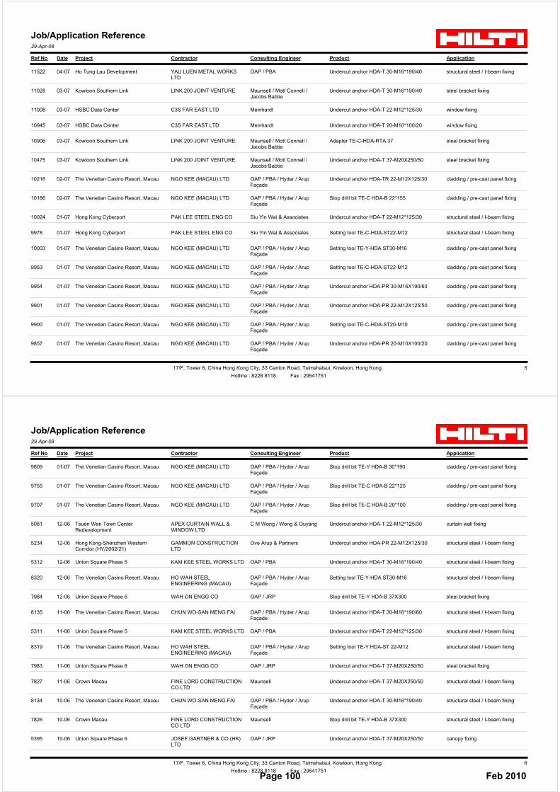
Ref No Date Project Contractor Consulting Engineer Product Application
Job/Application Reference29-Apr-08
11522 04-07 Ho Tung Lau Development YAU LUEN METAL WORKS LTD
OAP / PBA Undercut anchor HDA-T 30-M16*190/40 structural steel / I-beam fixing
11028 03-07 Kowloon Southern Link LINK 200 JOINT VENTURE Maunsell / Mott Connell / Jacobs Babtie
Undercut anchor HDA-T 30-M16*190/40 steel bracket fixing
11008 03-07 HSBC Data Center C3S FAR EAST LTD Meinhardt Undercut anchor HDA-T 22-M12*125/30 window fixing
10945 03-07 HSBC Data Center C3S FAR EAST LTD Meinhardt Undercut anchor HDA-T 20-M10*100/20 window fixing
10906 03-07 Kowloon Southern Link LINK 200 JOINT VENTURE Maunsell / Mott Connell / Jacobs Babtie
Adapter TE-C-HDA-RTA 37 steel bracket fixing
10475 03-07 Kowloon Southern Link LINK 200 JOINT VENTURE Maunsell / Mott Connell / Jacobs Babtie
Undercut anchor HDA-T 37-M20X250/50 steel bracket fixing
10216 02-07 The Venetian Casino Resort, Macau NGO KEE (MACAU) LTD OAP / PBA / Hyder / Arup Façade
Undercut anchor HDA-TR 22-M12X125/30 cladding / pre-cast panel fixing
10186 02-07 The Venetian Casino Resort, Macau NGO KEE (MACAU) LTD OAP / PBA / Hyder / Arup Façade
Stop drill bit TE-C HDA-B 22*155 cladding / pre-cast panel fixing
10024 01-07 Hong Kong Cyberport PAK LEE STEEL ENG CO Siu Yin Wai & Associates Undercut anchor HDA-T 22-M12*125/30 structural steel / I-beam fixing
9978 01-07 Hong Kong Cyberport PAK LEE STEEL ENG CO Siu Yin Wai & Associates Setting tool TE-C-HDA-ST22-M12 structural steel / I-beam fixing
10003 01-07 The Venetian Casino Resort, Macau NGO KEE (MACAU) LTD OAP / PBA / Hyder / Arup Façade
Setting tool TE-Y-HDA ST30-M16 cladding / pre-cast panel fixing
9953 01-07 The Venetian Casino Resort, Macau NGO KEE (MACAU) LTD OAP / PBA / Hyder / Arup Façade
Setting tool TE-C-HDA-ST22-M12 cladding / pre-cast panel fixing
9954 01-07 The Venetian Casino Resort, Macau NGO KEE (MACAU) LTD OAP / PBA / Hyder / Arup Façade
Undercut anchor HDA-PR 30-M16X190/60 cladding / pre-cast panel fixing
9901 01-07 The Venetian Casino Resort, Macau NGO KEE (MACAU) LTD OAP / PBA / Hyder / Arup Façade
Undercut anchor HDA-PR 22-M12X125/50 cladding / pre-cast panel fixing
9900 01-07 The Venetian Casino Resort, Macau NGO KEE (MACAU) LTD OAP / PBA / Hyder / Arup Façade
Setting tool TE-C-HDA-ST20-M10 cladding / pre-cast panel fixing
9857 01-07 The Venetian Casino Resort, Macau NGO KEE (MACAU) LTD OAP / PBA / Hyder / Arup Façade
Undercut anchor HDA-PR 20-M10X100/20 cladding / pre-cast panel fixing
17/F, Tower 6, China Hong Kong City, 33 Canton Road, Tsimshatsui, Kowloon, Hong Kong. 5
Hotline : 8228 8118 Fax : 29541751
Ref No Date Project Contractor Consulting Engineer Product Application
Job/Application Reference29-Apr-08
9809 01-07 The Venetian Casino Resort, Macau NGO KEE (MACAU) LTD OAP / PBA / Hyder / Arup Façade
Stop drill bit TE-Y HDA-B 30*190 cladding / pre-cast panel fixing
9755 01-07 The Venetian Casino Resort, Macau NGO KEE (MACAU) LTD OAP / PBA / Hyder / Arup Façade
Stop drill bit TE-C HDA-B 22*125 cladding / pre-cast panel fixing
9707 01-07 The Venetian Casino Resort, Macau NGO KEE (MACAU) LTD OAP / PBA / Hyder / Arup Façade
Stop drill bit TE-C HDA-B 20*100 cladding / pre-cast panel fixing
5081 12-06 Tsuen Wan Town Center Redevelopment
APEX CURTAIN WALL & WINDOW LTD
C M Wong / Wong & Ouyang Undercut anchor HDA-T 22-M12*125/30 curtain wall fixing
5234 12-06 Hong Kong-Shenzhen Western Corridor (HY/2002/21)
GAMMON CONSTRUCTION LTD
Ove Arup & Partners Undercut anchor HDA-PR 22-M12X125/30 structural steel / I-beam fixing
5312 12-06 Union Square Phase 5 KAM KEE STEEL WORKS LTD OAP / PBA Undercut anchor HDA-T 30-M16*190/40 structural steel / I-beam fixing
8320 12-06 The Venetian Casino Resort, Macau HO WAH STEEL ENGINEERING (MACAU)
OAP / PBA / Hyder / Arup Façade
Setting tool TE-Y-HDA ST30-M16 structural steel / I-beam fixing
7984 12-06 Union Square Phase 6 WAH ON ENGG CO OAP / JRP Stop drill bit TE-Y HDA-B 37X300 steel bracket fixing
8135 11-06 The Venetian Casino Resort, Macau CHUN WO-SAN MENG FAI OAP / PBA / Hyder / Arup Façade
Undercut anchor HDA-T 30-M16*190/60 structural steel / I-beam fixing
5311 11-06 Union Square Phase 5 KAM KEE STEEL WORKS LTD OAP / PBA Undercut anchor HDA-T 22-M12*125/30 structural steel / I-beam fixing
8319 11-06 The Venetian Casino Resort, Macau HO WAH STEEL ENGINEERING (MACAU)
OAP / PBA / Hyder / Arup Façade
Setting tool TE-Y HDA-ST 22-M12 structural steel / I-beam fixing
7983 11-06 Union Square Phase 6 WAH ON ENGG CO OAP / JRP Undercut anchor HDA-T 37-M20X250/50 steel bracket fixing
7827 11-06 Crown Macau FINE LORD CONSTRUCTION CO LTD
Maunsell Undercut anchor HDA-T 37-M20X250/50 structural steel / I-beam fixing
8134 10-06 The Venetian Casino Resort, Macau CHUN WO-SAN MENG FAI OAP / PBA / Hyder / Arup Façade
Undercut anchor HDA-T 30-M16*190/40 structural steel / I-beam fixing
7826 10-06 Crown Macau FINE LORD CONSTRUCTION CO LTD
Maunsell Stop drill bit TE-Y HDA-B 37X300 structural steel / I-beam fixing
5395 10-06 Union Square Phase 6 JOSEF GARTNER & CO (HK) LTD
OAP / JRP Undercut anchor HDA-T 37-M20X250/50 canopy fixing
17/F, Tower 6, China Hong Kong City, 33 Canton Road, Tsimshatsui, Kowloon, Hong Kong. 6
Hotline : 8228 8118 Fax : 29541751Page 100 Feb 2010

Ref No Date Project Contractor Consulting Engineer Product Application
Job/Application Reference29-Apr-08
8610 10-06 Las Vegas Sands Casino Extension, Macau
SMART HORSE MACHINE & ENGINEERING
OAP / PBA / Arup Façade Undercut anchor HDA-PF 30-M16X190/40 canopy fixing
7982 10-06 Union Square Phase 7 WAH ON ENGG CO OAP / JRP Stop drill bit TE-Y HDA-B 37X300 steel bracket fixing
8609 09-06 Las Vegas Sands Casino Extension, Macau
SMART HORSE MACHINE & ENGINEERING
OAP / PBA / Arup Façade Setting tool TE-Y-HDA ST30-M16 canopy fixing
8037 09-06 Union Square Phase 5 BOTH ARTS ENG CO OAP / PBA Undercut anchor HDA-T 22-M12*125/30 glass fencing / balustrade fixing
7981 09-06 Union Square Phase 6 WAH ON ENGG CO OAP / JRP Setting tool TE-Y-HDA-ST37-M20 steel bracket fixing
5082 09-06 Chelsea Court, Tsuen Wan APEX CURTAIN WALL & WINDOW LTD
Sun Hung Kai Engineering Undercut anchor HDA-TF 22-M12X125/50 curtain wall fixing
5394 09-06 Union Square Phase 6 JOSEF GARTNER & CO (HK) LTD
OAP / JRP Undercut anchor HDA-T 22-M12*125/30 canopy fixing
7840 08-06 Las Vegas Sands Casino Extension, Macau
HO WAH STEEL ENG CO LTD OAP / PBA / Arup Façade Setting tool TE-Y-HDA-ST37-M20 structural steel / I-beam fixing
8484 08-06 The Venetian Casino Resort, Macau NGO KEE (MACAU) LTD OAP / PBA / Hyder / Arup Façade
Undercut anchor HDA-PR 30-M16X190/60 cladding / pre-cast panel fixing
5155 08-06 Enterprise Square 5 PERMASTEELISA HONG KONG LTD
Siu Yin Wai / Meinhardt Undercut anchor HDA-PR 22-M12X125/30 curtain wall fixing
8595 07-06 The Venetian Casino Resort, Macau SHU KEE CONSTRUCTION (MACAU) LTD
OAP / PBA / Hyder / Arup Façade
Undercut anchor HDA-PR 22-M12X125/30 cladding / pre-cast panel fixing
5044 07-06 Science Park YAU LEE CONST CO LTD Maunsell / Meinhardt Undercut anchor HDA-T 22-M12*125/30 curtain wall fixing
8483 07-06 The Venetian Casino Resort, Macau NGO KEE (MACAU) LTD OAP / PBA / Hyder / Arup Façade
Undercut anchor HDA-PR 22-M12X125/50 cladding / pre-cast panel fixing
4996 07-06 Lok Ma Chau Terminus and Associated Works (LCC-300)
MAEDA CORPORATION Mott Connell Undercut anchor HDA-T 37-M20X250/50 rebar fastening
5250 07-06 Science Park Phase 2 BUILD FAME SERVICES LTD Meinhardt / Maunsell Undercut anchor HDA-T 22-M12*125/30 structural steel / I-beam fixing
8035 07-06 Union Square Phase 5 BOTH ARTS ENG CO OAP / PBA Setting tool TE-C-HDA-ST22-M12 glass fencing / balustrade fixing
17/F, Tower 6, China Hong Kong City, 33 Canton Road, Tsimshatsui, Kowloon, Hong Kong. 7
Hotline : 8228 8118 Fax : 29541751
Ref No Date Project Contractor Consulting Engineer Product Application
Job/Application Reference29-Apr-08
8327 07-06 The Venetian Casino Resort, Macau HO WAH STEEL ENGINEERING (MACAU)
OAP / PBA / Hyder / Arup Façade
Undercut anchor HDA-T 30-M16*190/60 structural steel / I-beam fixing
8326 06-06 The Venetian Casino Resort, Macau HO WAH STEEL ENGINEERING (MACAU)
OAP / PBA / Hyder / Arup Façade
Undercut anchor HDA-T 30-M16*190/40 structural steel / I-beam fixing
8482 06-06 The Venetian Casino Resort, Macau NGO KEE (MACAU) LTD OAP / PBA / Hyder / Arup Façade
Undercut anchor HDA-PR 22-M12X125/30 cladding / pre-cast panel fixing
8594 06-06 The Venetian Casino Resort, Macau SHU KEE CONSTRUCTION (MACAU) LTD
OAP / PBA / Hyder / Arup Façade
Undercut anchor HDA-PR 20-M10X100/20 cladding / pre-cast panel fixing
5348 06-06 Improvement to Sheung Shui Station and Associated Works (LCC-204)
POLLARD CONST CO LTD Meinhardt Undercut anchor HDA-P 22-M12*125/30 structural steel / I-beam fixing
8593 05-06 The Venetian Casino Resort, Macau SHU KEE CONSTRUCTION (MACAU) LTD
OAP / PBA / Hyder / Arup Façade
Stop drill bit TE-C HDA-B 22*125 cladding / pre-cast panel fixing
8465 05-06 The Venetian Casino Resort, Macau NGO KEE (MACAU) LTD OAP / PBA / Hyder / Arup Façade
Setting tool TE-Y-HDA ST30-M16 cladding / pre-cast panel fixing
8481 05-06 The Venetian Casino Resort, Macau NGO KEE (MACAU) LTD OAP / PBA / Hyder / Arup Façade
Undercut anchor HDA-PR 20-M10X100/20 cladding / pre-cast panel fixing
8325 05-06 The Venetian Casino Resort, Macau HO WAH STEEL ENGINEERING (MACAU)
OAP / PBA / Hyder / Arup Façade
Undercut anchor HDA-T 22-M12*125/50 structural steel / I-beam fixing
8480 04-06 The Venetian Casino Resort, Macau NGO KEE (MACAU) LTD OAP / PBA / Hyder / Arup Façade
Stop drill bit TE-Y HDA-B 30*190 cladding / pre-cast panel fixing
8592 04-06 The Venetian Casino Resort, Macau SHU KEE CONSTRUCTION (MACAU) LTD
OAP / PBA / Hyder / Arup Façade
Stop drill bit TE-C HDA-B 20*100 cladding / pre-cast panel fixing
5319 04-06 Union Square Phase 6 KAM KEE STEEL WORKS LTD OAP / JRP Undercut anchor HDA-T 30-M16*190/40 structural steel / I-beam fixing
8464 04-06 The Venetian Casino Resort, Macau NGO KEE (MACAU) LTD OAP / PBA / Hyder / Arup Façade
Setting tool TE-C-HDA-ST22-M12 cladding / pre-cast panel fixing
8588 04-06 The Venetian Casino Resort, Macau SHU KEE CONSTRUCTION (MACAU) LTD
OAP / PBA / Hyder / Arup Façade
Setting tool TE-C-HDA-ST20-M10 cladding / pre-cast panel fixing
7820 04-06 Crown Macau FINE LORD CONSTRUCTION CO LTD
Maunsell Setting tool TE-Y-HDA-ST37-M20 structural steel / I-beam fixing
17/F, Tower 6, China Hong Kong City, 33 Canton Road, Tsimshatsui, Kowloon, Hong Kong. 8
Hotline : 8228 8118 Fax : 29541751Page 101 Feb 2010

Ref No Date Project Contractor Consulting Engineer Product Application
Job/Application Reference29-Apr-08
8324 04-06 The Venetian Casino Resort, Macau HO WAH STEEL ENGINEERING (MACAU)
OAP / PBA / Hyder / Arup Façade
Undercut anchor HDA-T 22-M12*125/30 structural steel / I-beam fixing
8479 03-06 The Venetian Casino Resort, Macau NGO KEE (MACAU) LTD OAP / PBA / Hyder / Arup Façade
Stop drill bit TE-C HDA-B 22*125 cladding / pre-cast panel fixing
5115 03-06 Union Square Phase 5 JOSEF GARTNER & CO (HK) LTD
OAP / PBA Undercut anchor HDA-T 37-M20X250/50 curtain wall fixing
8463 03-06 The Venetian Casino Resort, Macau NGO KEE (MACAU) LTD OAP / PBA / Hyder / Arup Façade
Setting tool TE-C-HDA-ST20-M10 cladding / pre-cast panel fixing
8671 03-06 Macau Fisherman's Wharf SUN KOU NGAI CONST. MATERIAL & ENG.
Civil Engineering Consultants / Tecproeng Macau
Setting tool TE-Y-HDA-ST37-M20 structural steel / I-beam fixing
5362 02-06 Union Square Phase 6 CHUN KEE ENGRG & CONST CO LTD
OAP / JRP Undercut anchor HDA-T 30-M16*190/60 structural steel / I-beam fixing
5237 02-06 Shatin Heights Tunnel and Approaches (ST 89/02)
GAMMON CONSTRUCTION LTD
Maunsell Undercut anchor HDA-PR 30-M16X190/60 structural steel / I-beam fixing
8478 02-06 The Venetian Casino Resort, Macau NGO KEE (MACAU) LTD OAP / PBA / Hyder / Arup Façade
Stop drill bit TE-C HDA-B 20*100 cladding / pre-cast panel fixing
8674 02-06 Macau Fisherman's Wharf SUN KOU NGAI CONST. MATERIAL & ENG.
Civil Engineering Consultants / Tecproeng Macau
Undercut anchor HDA-T 37-M20X250/50 structural steel / I-beam fixing
5114 02-06 Union Square Phase 5 JOSEF GARTNER & CO (HK) LTD
OAP / PBA Undercut anchor HDA-T 37-M20X250/100 curtain wall fixing
8589 01-06 The Venetian Casino Resort, Macau SHU KEE CONSTRUCTION (MACAU) LTD
OAP / PBA / Hyder / Arup Façade
Setting tool TE-C-HDA-ST22-M12 cladding / pre-cast panel fixing
8673 01-06 Macau Fisherman's Wharf SUN KOU NGAI CONST. MATERIAL & ENG.
Civil Engineering Consultants / Tecproeng Macau
Stop drill bit TE-Y HDA-B 37X300 structural steel / I-beam fixing
7985 01-06 Union Square Phase 7 WAH ON ENGG CO OAP / JRP Undercut anchor HDA-T 37-M20X250/50 steel bracket fixing
17/F, Tower 6, China Hong Kong City, 33 Canton Road, Tsimshatsui, Kowloon, Hong Kong. 9
Hotline : 8228 8118 Fax : 29541751
Page 102 Feb 2010