Embed Size (px)
Citation preview

HILLSBOROUGH COUNTY
FLORIDA
REQUEST FOR PROPOSALS
FOR
SPRINGHEAD FIRE STATION NO. 25 REPLACEMENT
(CIP NO. 91164)
&
SOUTH BRANDON FIRE STATION NO. 7 REPLACEMENT (CIP NO. 91176)
CONSTRUCTION MANAGER (CM) AT-RISK Volume 2 of 5
(Technical Specifications – Springhead Fire Station Part 1 of 2)
RFP NO. : C-0146-0-2014/DV
CONTACT PERSON:
DENISE VASQUEZ SENIOR PROCUREMENT ANALYST
BUSINESS & SUPPORT SERVICES (PROCUREMENT) 601 E. KENNEDY BLVD., 18TH FLOOR
P.O. BOX 1110 TAMPA, FLORIDA 33602
TELEPHONE: (813) 301-7097
FAX: (813) 272-6290

TABLE OF CONTENTS SPRINGHEAD FIRE STATION No. 25 REPLACEMENT
DIVISION 1 – GENERAL REQUIREMENTS
01010 SUMMARY OF WORK 01030 ALTERNATES/OPTIONS 01040 PROJECT COORDINATION 01045 CUTTING & PATCHING 01050 FIELD ENGINEERING 01070 ABBREVIATIONS 01095 REFERENCE STANDARDS AND DEFINITIONS 01200 MEETINGS & CONFERENCES01300 CONSTRUCTION MANAGER SUBMITTALS 01310 BAR CHART SCHEDULE 01340 SHOP DRAWINGS, PRODUCT DATA AND SAMPLES 01400 QUALITY CONTROL 01410 MATERIALS TESTING 01500 TEMPORARY FACILITIES 01505 MOBILIZATION 01530 BARRICADES 01560 TEMPORARY ENVIRONMENTAL CONTROLS 01600 MATERIALS AND EQUIPMENT 01610 FLORIDA PRODUCT APPROVAL REQUIREMENTS 01631 SUBSTITUTIONS 01700 PROJECT CLOSE-OUT 01710 FINAL CLEANING 01720 PROJECT RECORD DOCUMENTS 01730 OPERATING AND MAINTENANCE DATA 01740 WARRANTIES
DIVISION 2 – SITEWORK
02070 SITE DEMOLITION 02110 SITE CLEARING 02300 EARTHWORK 02361 TERMITE CONTROL 02480 LANDSCAPE WORK 02513 ASPHALT CONCRETE PAVING 02666 POTABLE WATER SYSTEMS 02668 FIRE WATER SYSTEMS 02670 WATER WELL SYSTEMS 02720 STORM SEWAGE SYSTEMS 02740 SEPTIC SYSTEMS 02810 UNDERGROUND IRRIGATION SYSTEM 02821 CHAIN-LINK FENCES
DIVISION 3 - CONCRETE
03300 CAST-IN-PLACE CONCRETE
SPRINGHEAD FIRE STATION NO. 25 REPLACEMENT TABLE OF CONTENTS CIP NO. 91164 TOC - 1

DIVISION 4 - MASONRY
04810 UNIT MASONRY ASSEMBLIES
DIVISION 5 - METALS
NOT USED
DIVISION 6 – WOOD AND PLASTICS
06100 ROUGH CARPENTRY 06176 METAL-PLATE CONNECTED WOOD TRUSSES 06201 EXTERIOR FINISH CARPENTRY 06410 PLASTIC LAMINATE CASEWORK
DIVISION 7 – THERMAL AND MOISTURE PROTECTION
07180 POLYURETHANE DECK COATING 07210 BUILDING INSULATION 07411 METAL ROOF PANELS 07620 SHEET METAL FLASHING & TRIM 07841 FIRESTOP SYSTEM 07920 JOINT SEALANTS
DIVISION 8 – DOORS AND WINDOWS
08111 STANDARD STEEL DOORS & FRAMES 08211 FLUSH WOOD DOORS 08361 SECTIONAL OVERHEAD DOORS 08410 ALUMINUM ENTRANCES & STOREFRONT 08520 ALUMINUM WINDOWS 08710 DOOR HARDWARE 08800 GLAZING
DIVISION 9 – FINISHES
09220 PORTLAND CEMENT PLASTER 09260 GYPSUM BOARD ASSEMBLIES 09310 CERAMIC TILE 09511 ACOUSTICAL PANEL CEILINGS 09650 RESILIENT FLOORING 09653 RESILIENT WALL BASE AND ACCESSORIES 09900 PAINTING
DIVISION 10 – SPECIALTIES
10200 LOUVERS & VENTS 10350 FLAGPOLES 10431 SIGNS 10522 FIRE EXTINGUISHER, CABINETS & ACCESSORIES 10800 TOILET & BATH ACCESSORIES DIVISION 11 – EQUIPMENT
SPRINGHEAD FIRE STATION NO. 25 REPLACEMENT TABLE OF CONTENTS CIP NO. 91164 TOC - 2

11451 RESIDENTIAL APPLIANCES
DIVISION 12 – FURNISHINGS
12491 HORIZONTAL LOUVER BLINDS
DIVISION 13 – SPECIAL CONSTRUCTION
NOT USED
DIVISION 14 – CONVEYING SYSTEMS
NOT USED
DIVISION 15 – MECHANICAL
15010 BASIC MECHANICAL REQUIREMENTS 15140 SUPPORTS AND ANCHORS 15170 MOTORS 15190 MECHANICAL IDENTIFICATION 15242 VIBRATION ISOLATION 15260 PIPING INSULATION 15280 EQUIPMENT INSULATION 15290 DUCTWORK INSULATION 15310 FIRE PROTECTION PIPING SYSTEMS 15400 TESTING OF PIPING SYSTEMS 15401 DUAL WALL CONTAINMENT PIPING 15410 PLUMBING PIPING 15420 KITCHEN CANOPY AND DUCT FIRE PROTECTION 15430 PLUMBING SPECIALTIES 15440 PLUMBING FIXTURES 15450 PLUMBING EQUIPMENT 15535 REFRIGERANT PIPING AND SPECIALTIES 15671 AIR COOLED CONDENSING UNITS 15790 ELECTRIC DUCT HEATERS 15836 SPLIT SYSTEM AIR HANDLER 15856 100% OUTSIDE AIR DEHUMIDIFICATION UNIT 15870 POWER VENTILATORS 15875 POWER ROOF VENTILATORS 15890 DUCTWORK 15910 DUCTWORK ACCESSORIES 15911 KITCHEN EXHAUST CANOPY 15936 AIR OUTLETS AND INLETS 15990 TESTING, ADJUSTING, AND BALANCING
DIVISION 16 – ELECTRICAL
16010 BASIC ELECTRICAL REQUIREMENTS 16111 CONDUIT 16120 BUILDING WIRE AND CABLE 16130 BOXES
SPRINGHEAD FIRE STATION NO. 25 REPLACEMENT TABLE OF CONTENTS CIP NO. 91164 TOC - 3

SPRINGHEAD FIRE STATION NO. 25 REPLACEMENT TABLE OF CONTENTS CIP NO. 91164 TOC - 4
16141 WIRING DEVICES 16160 CABINETS AND ENCLOSURES 16170 GROUNDING AND BONDING 16180 WIRING SYSTEMS 16190 SUPPORTING DEVICES 16195 ELECTRICAL IDENTIFICATION 16401 ABOVE GROUND STORAGE TANK EQUIPMENT (DIESEL) 16402 ABOVE GROUND STORAE TANK EQUIPMENT (UNLEADED) 16420 SERVICE ENTRANCE 16425 SWITCHBOARDS 16440 DISCONNECT SWITCHES 16461 DRY TYPE TRANSFORMERS 16470 PANELBOARDS 16480 MOTOR CONTROL 16485 CONTACTORS 16495 TRANSFER SWITCH 16510 LUMINAIRES 16530 SITE LIGHTING 16600 TRANSIENT VOLTAGE SURGE SUPPRESSION(TVSS) 16622 PACKAGED ENGINE GENERATOR SYSTEMS 16670 LIGHTNING PROTECTION SYSTEMS 16720 FIRE ALARM AND SMOKE DETECTION SYSTEMS 16741 TELEPHONE SERVICE ENTRANCE 16742 STRUCTURED CABLING 16760 INTERCOMMUNICTION SYSTEM 16781 TELEVISION DISTRIBUTION SYSTEM
Schedule A – REPORT OF THE SUBSURFACE EXPLORATION AND GEOTECHNICAL EVALUATION SERVICES
END OF TABLE OF CONTENTS

SECTION 01010 – SUMMARY OF WORK
PART 1 - GENERAL
1.1 RELATED DOCUMENTS
Drawings and general provisions of the Contract, including General and Special Conditions, other Division-1 Specification Sections, and the CM-AT Risk GMP RFP Package “RFP” apply to this Section.
1.2 SUMMARY OF CONSTRUCTION MANAGER’S (CM’S) SCOPE OF WORK
The Summary of CM’S Scope of Work is generally described herein In general, the names of the Projects are the “Springhead Fire Station Replacement”. The Work includes but is not limited to the furnishing of all labor, materials, equipment, permitting services, field engineering, construction management, and project administration/supervision activities to construct fully finished and functional fire station. The facility must be of high quality and low maintenance; must meet or exceed the requirements of the GMP Construction Documents Package and must meet the needs of the user and maintenance agencies. The construction of this facility shall meet the requirements of all governing local, state and federal regulations, codes and ordinances, including the Florida Accessibility Code for Building Construction and the Americans with Disabilities Act (ADA).
1.1.2 The Location information for the Project is as follows:
1. Springhead Fire Station No. 25 Replacement (CIP No 91164): 2606 E Trapnell Road, Plant City, Florida.
1.1.3 Generally the construction work for the Springhead fire station facility includes, but is not limited to: construction of a single story approximately 9,000 sq ft. 3-bay fire station building, together with all associated on-site and off-site improvements such as access drives, parking lot, dumpster enclosure, sign, flagpole, landscaping, irrigation, storm drainage system, sidewalks, fences, refueling facility and all necessary utilities, including a fire sprinkler system (NFPA 13 system.)
A. In general, the Work includes but is not limited to the furnishing of all labor, materials, equipment, permitting services, field engineering, construction management, and project administration/supervision activities to construct a fully finished and functional facility. The facility must be of high quality and low maintenance; must meet or exceed the requirements of the GMP Construction Documents Package and must meet the needs of the user and maintenance agencies. The construction of the facility shall meet the requirements of all governing local, state and federal regulations, codes and ordinances, including the Florida Accessibility Code for Building Construction and the Americans with Disabilities Act (ADA).
B. The Construction Documents also include certain Alternates and Options which may or may not be included as part of the Work at the COUNTY’S option. These alternates and options are listed in Section 01030 Alternates and Options of Division One Specifications.
1.3. CONSTRUCTION MANAGER’S WORK
The CM’S construction Work shall include, but shall not be limited to the furnishing of all labor, materials, equipment, and project administration/supervision activities, including scheduling, to construct one fully finished facility which meets or exceeds the program and standards set forth in the RFP as follows:
A. Obtaining all permits and approvals from regulatory and utility agencies.
SPRINGHEAD FIRE STATION NO. 25 REPLACEMENT SUMMARY OF WORK CIP NO. 91164 01010 - 1

B. All required on-site and off-site work associated with the project including but not limited to access drives, sidewalks, parking, signage, flagpole, refueling facility, landscaping and irrigation, water and wastewater connections and extensions, electrical utility services, fire protection, storm water retention system, etc.
C. Construction of one complete, functional fire station facility as described in the GMP documents.
D. The work includes all associated equipment and building systems as described in the GMP drawings and specifications including mechanical systems, water and sanitary systems, fire protection, electrical systems, conduit and wiring for data/telecommunications, emergency generator, 911 call system , etc.
E. Provision of all close-out documents, including but not limited to as-built surveys and drawings, maintenance manuals, warranties and guarantees as described in Division 1 of the Specifications, Section 01700 “Project Close-out.” This is to include, but not be limited to the following:
1. Training for COUNTY’S Facilities Management and other personnel on the maintenance and operation of all systems, including video taping of all training classes.
2. Post-construction warranty and guarantee services including standard and extended warranties.
1.4 CONSTRUCTION MILESTONES
A. The CM shall achieve the Milestone Dates described in Attachment “B” of this “RFP”.
B. The CM must provide a Guaranteed Schedule to meet the above stated completion milestone dates. Earlier completion than those dates stated above are not required and will not necessarily be accepted by the COUNTY.
C. No later than one month prior to Substantial Completion date, the CM coordinate all testing, and inspections of systems and facilities with the Vendors and Testing Engineers.
1.5 WORK BY OTHERS
A. The CM’S attention is directed to the fact that Work may be conducted at the site by other contractors during the performance of the Work under this Contract. The CM shall conduct the operations so as to cause a minimum of interference with the Work of such other contractors and shall cooperate fully with such contractors and the project representative to provide continued safe access to their respective portions of the site, as required too perform their respective contracts.
1.6 NOISE CONTROL
CM shall eliminate noise within the project area to the extent possible. All local ordinances and regulations covering noise control shall be observed.
1.7 STORAGE
Storage conditions shall be acceptable to COUNTY for all materials and equipment not incorporated into the Work but included in Applications for Payment. Such storage arrangements and conditions shall be presented in writing for COUNTY'S review and approval and shall afford adequate and satisfactory security and protection. Off-site storage facilities shall be accessible to Project Manager. The stored materials shall be insured for full value. Certificates of liability insurance coverage must be submitted to the Project Manager with the request for payment by the CM. All arrangements and costs for storage facilities shall be paid by the
SPRINGHEAD FIRE STATION NO. 25 REPLACEMENT SUMMARY OF WORK CIP NO. 91164 01010 - 2

SPRINGHEAD FIRE STATION NO. 25 REPLACEMENT SUMMARY OF WORK CIP NO. 91164 01010 - 3
CONSTRUCTION MANAGER.1.8 NOTICES TO OWNERS AND AUTHORITIES
A. CONSTRUCTION MANGER shall notify all property owners and owners of utilities when prosecution of the Work may affect them.
B. CM shall review with the various utility companies the construction methods and work to be done in the vicinity of utilities.
1.9 REFERENCE STANDARDS
Reference to the standards of any technical society, organization, or association or to codes of local or state authorities shall mean the latest effective standard, code, specification, or standard adopted and published at the date of receipt of bids, unless specifically stated otherwise.
1.10 DUST/DIRT CONTROL
The CM shall be careful not to create dust, dirt or contamination of adjoining active storm drain and channel waters during demolition or other activities. The CM is responsible for any and all damage as a result of the Work.
PART 2 - PRODUCTS (Not applicable)
PART 3 - EXECUTION (Not applicable)
END OF SECTION01010

SECTION 01030 – ALTERNATES
PART 1 - GENERAL
1.1 SUMMARY
A. Drawings and general provisions of Contract, including General and Special Conditions and other Division 1 Specification Sections, apply to this Section.
B. This Section includes a Schedule of Alternates and includes administrative and procedural requirements governing Alternates.
1.2 DEFINITIONS
A. Definition: An alternate is an amount proposed by CONSTRUCTION MANAGER (CM) and stated on the GMP Proposal for certain work defined in the Agreement that may be added to or deducted from the GMP amount if the COUNTY decides to accept a corresponding change in either the amount of construction to be completed, or in the products, materials, equipment, systems, or installation methods described in the Contract Documents.
1. The cost or credit for each alternate is the net addition to or deduction from the CM’S Construction Price to incorporate the Alternate into the Work. No other adjustments are made to the GMP.
1.3 PROCEDURES
A. Coordination: Modify or adjust affected adjacent Work as necessary to fully integrate that Work into the Project.
1. Include as part of each alternate, miscellaneous devices, accessory objects, and similar items incidental to or required for a complete installation whether or not mentioned as part of the Alternate.
B. Schedule: A “Schedule of alternates” is included in this Section. Specifications Sections referenced in the Schedule contain requirements for materials necessary to achieve the Work described under each alternate.
PART 2 - PRODUCTS (Not Applicable)
PART 3 – EXECUTION - SCHEDULE OF ALTERNATES AND OPTIONS
3.1 SCHEDULE OF ALTERNATES
3.1.1 SPRINGHEAD FIRE STATION NO. 25 REPLACEMENT:
1. Alternate No. 1. Headboard & Scuff Rails: GMP: Provide Headboard with its attached shelf and Scuff Rail in all bunk rooms as indicated on Sheet A7.1, detail K5 (1 &2), & Sheet A7.3 , detail G14, E14 & C14.
Deductive Alternate: Provide a credit to delete Headboards with attached shelf & Scuff Rail in all bunk rooms.
Deduct from GMCP
SPRINGHEAD FIRE STATION NO. 25 REPLACEMENT ALTERNATESCIP NO. 91164 01030 - 1
SPRINGHEAD FIRE STATION NO. 25 REPLACEMENT ALTERNATESCIP NO. 91164 01030 - 2
2. Alternate No. 2. Lightning Protection System: GMP: Provide lightning protection system as per specification Section 16670.
Deductive Alternate: Provide a credit to delete lightning protection system in its entirety.
Deduct from GMCP
3. Alternate No. 3. Aboveground Gasoline Fuel Tank:GMP: Provide a 200 gallon above-ground gasoline fuel tank and associated electrical, fuel dispenser assembly and concrete pad as indicated in specifications and drawings.
Deductive Alternate: Provide a cost to delete the 200 gallon above-ground gasoline fuel tank with its associated fuel dispenser assembly. Note: Provision of concrete pad for the fuel tank, emergency cut-off switch and electrical stub out at proposed tank pad to remain part of the Work.
Deduct from GMCP
4. Alternate No. 4. Pre-Engineered Metal Building:GMP: Drawing Sheet indicates an 18’ x 21’ pre-engineered metal building with associated concrete pad and electrical work. The pre-engineered building is not included in the base GMP.
Additive Alternate: Provide a cost to add the 18’ x 21’pre-engineered building.
Note: Concrete pad and associated electrical work for the Pre-engineered Building to remain in GMP.
Add to GMCP
END OF SECTION 01030

SECTION 01040 - PROJECT COORDINATION
PART 1 - GENERAL
1.1 RELATED DOCUMENTS
A. Drawings and general provisions of Contract, including General and Special Conditions and other Division 1 Specification Sections, apply to this Section.
1.2 SUMMARY
A. This Section specifies administrative and supervisory requirements necessary for the Projects coordination including, but not necessarily limited to:
1. Coordination 2. General installation provisions
3. Cleaning and protection 4. Administrative and supervisory personnel 5. Security procedures
B. Progress meetings, coordination meetings and pre-installation conferences are included in SECTION 01200 - MEETINGS AND CONFERENCES.
C. Requirements for the CONSTRUCTION MANAGER'S Construction Schedule are included in SECTION 01300 - CONSTRUCTION MANAGER SUBMITTALS.
1.3 COORDINATION
A. Coordination: Coordinate construction activities included under various Sections of these Specifications to assure efficient and orderly installation of each part of the Work for both sites. Coordinate construction operations included under different Sections of the Specifications that are dependent upon each other for proper installation, connection, and operation.
1. Where installation of one part of the Work is dependent on installation of other components, either before or after its own installation, schedule construction activities in the sequence required to obtain the best results.
2. Where availability of space is limited, coordinate installation of different components to assure maximum accessibility for required maintenance, service and repair.
3. Make adequate provisions to accommodate items scheduled for later installation. 4. Coordinate work and delivery of materials for both sites.
B. Where necessary, prepare memoranda for distribution to each party involved outlining special procedures required for coordination. Include such items as required notices, reports, and attendance at meetings.
C. Administrative Procedures: Coordinate scheduling and timing of required administrative procedures with other construction activities to avoid conflicts and ensure orderly progress of the Work. Such administrative activities include, but are not limited to, the following:
1. Preparation of schedules 2. Installation and removal of temporary facilities
3. Delivery and processing of submittals. 4. Maintenance of record drawings.
SPRINGHEAD FIRE STATION NO. 25 REPLACEMENT PROJECT COORDINATION CIP No. 91164 01040 - 1

5. Progress meetings. 6. Projects Closeout activities.
D. Conservation: Coordinate construction activities to ensure that operations are carried out with consideration given to conservation of energy, water, and materials.
1. Salvage materials and equipment involved in performance of, but not actually incorporated in, the Work. Refer to other sections for disposition of salvaged materials that are designated as COUNTY'S property.
1.4 SUBMITTALS
A. Coordination Drawings: Prepare and submit Coordination Drawings where close and careful coordination is required for installation of products and materials fabricated offsite by separate entities and where limited space availability necessitates maximum utilization of space for efficient installation of different components.
1. Show the interrelationship of components shown on separate Shop Drawings. 2. Indicate required installation sequences. 3. Comply with requirements contained in SECTION 01300 – CONSTRUCTION MANAGER
SUBMITTALS.4. Refer to Division 15 and Division 16 for specific Coordination Drawing requirements for
mechanical and electrical installations.
PART 2 - PRODUCTS (NOT APPLICABLE).
PART 3 - EXECUTION
3.1 GENERAL INSTALLATION PROVISIONS
A. Inspection of Conditions: Require the Installer of each major component to inspect both the substrate and conditions under which Work is to be performed. Do not proceed until unsatisfactory conditions have been corrected in an acceptable manner.
B. Manufacturer's Instructions: Comply with manufacturer's installation instructions and recommendations, to the extent that those instructions and recommendations are more explicit or stringent than requirements contained in Contract Documents.
C. Inspect materials or equipment immediately upon delivery and again prior to installation. Reject damaged and defective items.
D. Provide attachment and connection devices and methods necessary for securing Work. Secure Work true to line and level. Allow for expansion and building movement.
E. Visual Effects: Provide uniform joint widths in exposed Work. Arrange joints in exposed Work to obtain the best visual effect. Refer questionable choices to the Project Manager for final decision.
F. Recheck measurements and dimensions, before starting each installation.
G. Install each component during weather conditions and Project status that will ensure the best possible
SPRINGHEAD FIRE STATION NO. 25 REPLACEMENT PROJECT COORDINATION CIP No. 91164 01040 - 2

SPRINGHEAD FIRE STATION NO. 25 REPLACEMENT PROJECT COORDINATION CIP No. 91164 01040 - 3
results. Isolate each part of the completed construction from incompatible material as necessary to prevent deterioration.
H. Coordinate temporary enclosures with required inspections and tests, to minimize the necessity of uncovering completed construction for that purpose.
I. Mounting Heights: Where mounting heights are not indicated, refer mounting height decisions to the Project Manager for final decision.
3.2 CLEANING AND PROTECTION
A. During handling and installation, clean and protect construction in progress and adjoining materials in place. Apply protective covering where required to ensure protection from damage or deterioration at Substantial Completion.
B. Clean and maintain completed construction as frequently as necessary through the remainder of the construction period. Adjust and lubricate operable components to ensure operability without damaging effects.
C. Limiting Exposures: Supervise construction activities to ensure that no part of the construction, completed or in progress, is subject to harmful, dangerous, damaging, or otherwise deleterious exposure during the construction period. Where applicable, such exposures include, but are not limited to, the following:
1. Excessive static or dynamic loading. 2. Excessively high humidity. 3. Water. 4. Heavy traffic. 5. Soiling, staining and corrosion. 6. Combustion. 7. Unusual wear or other misuse. 8. Contact between incompatible materials. 9. Excessive weathering. 10. Theft. 11. Vandalism.
END OF SECTION 01040

SECTION 01045 – CUTTING AND PATCHING
PART 1 - GENERAL
1.1 RELATED REQUIREMENTS
A. General provisions of Contract, including General and Supplementary Conditions.
B. Refer to Division-15 and Division-16 Sections for other requirements and limitations applicable to cutting and patching mechanical and electrical installations.
1.2 SECTION INCLUDES
A. Administrative and procedural requirements for cutting and patching.
1.3 SUBMITTALS
A. Cutting and Patching Proposal: Submit a proposal describing procedures well in advance of the time cutting and patching will be performed and request approval to proceed. Include the following information, as applicable, in the proposal: 1. Describe the extent of cutting and patching required and how it is to be performed; indicate
why it cannot be avoided. 2. Describe anticipated results in terms of changes to existing construction; include changes to
structural elements and operating components as well as changes in the building’s appearance and other visual elements.
3. List products to be used and firms or entities that will perform Work. 4. Indicate dates when cutting and patching is to be performed. 5. List utilities that will be disturbed or affected, including those that will be relocated and those
that will be temporarily out-of-service. Indicate how long service will be disrupted. 6. Where cutting and patching involves addition of reinforcement to structural elements, submit
details and engineering calculations to show how reinforcement is integrated with the original structure.
B. Approval by the PROJECT MANAGER and PROFESSIONAL to proceed with cutting and patching does not waive the PROJECT MANAGER and PROFESSIONAL’S right to later require complete removal and replacement of a part of the Work found to be unsatisfactory.
1.4 QUALITY ASSURANCE
A. Requirements for Structural Work: Do not cut and patch structural elements in a manner that would reduce their load-carrying capacity or load-deflection ratio.
B. Operational and Safety Limitations: Do not cut and patch operating elements or safety related components in a manner that would result in reducing their capacity to perform as intended, or result in increased maintenance, or decreased operational life or safety.
C. Visual Requirements: Do not cut and patch construction exposed on the exterior or in occupied spaces, in a manner that would, in the PROJECT MANAGER and PROFESSIONAL’S opinion, reduce the building’s aesthetic qualities, or result in visual evidence of cutting and patching. Remove and replace Work cut and patched in a visually unsatisfactory manner.
SPRINGHEAD FIRE STATION NO. 25 REPLACEMENT CUTTING AND PATCHING CIP No. 91164 01045 - 1

PART 2 - PRODUCTS
2.1 MATERIALS
A. Use materials that are identical to existing materials. If identical materials are not available or cannot be used where exposed surfaces are involved, use materials that match existing adjacent surfaces to the fullest extent possible with regard to visual effect.
B. Use materials whose installed performance will equal or surpass that of existing materials.
PART 3 - EXECUTION
3.1 EXAMINATION
A. Before cutting existing surfaces, examine surfaces to be cut and patched and conditions under which cutting and patching is to be performed. Take corrective action before proceeding.
B. Review areas of potential interference and conflict with trades involved. Coordinate procedures and resolve potential conflicts before proceeding.
3.2 PREPARATION
A. Provide temporary support of Work to be cut.
B. Protect existing construction during cutting and patching to prevent damage. Provide protection from adverse weather conditions for portions of the Project that might be exposed during cutting and patching operations.
C. Avoid interference with use of adjoining areas or interruption of free passage to adjoining areas.
3.3 PERFORMANCE
A. Employ skilled workmen to perform cutting and patching. Proceed with cutting and patching at the earliest feasible time and complete without delay.
B. Cut existing construction using methods least likely to damage elements to be retained or adjoining construction.
1. In general, where cutting is required use hand or small power tools designed for sawing or grinding, not hammering and chopping. Cut holes and slots neatly to size required with minimum disturbance of adjacent surfaces. Temporarily cover openings when not in use.
2. To avoid marring existing finished surfaces, cut or drill from the exposed or finished side into concealed surfaces.
3. Cut through concrete and masonry using a cutting machine such as a carborundum saw or diamond core drill.
4. By-pass utility services such as pipe or conduit, before cutting, where services are shown or required to be removed, relocated or abandoned. Cut-off pipe or conduit in walls or partitions to be removed. Cap, valve or plug and seal the remaining portion of pipe or conduit to prevent entrance of moisture or other foreign matter after by-passing and cutting.
SPRINGHEAD FIRE STATION NO. 25 REPLACEMENT CUTTING AND PATCHING CIP No. 91164 01045 - 2

SPRINGHEAD FIRE STATION NO. 25 REPLACEMENT CUTTING AND PATCHING CIP No. 91164 01045 - 3
C. Patch with durable seams that are as invisible as possible. Comply with specified tolerances.
1. Inspect and test patched areas to demonstrate integrity of the installation.
2. Restore exposed finishes of patched areas and extend finish restoration into retained adjoining construction in a manner that will eliminate evidence of patching and refinishing.
3. Where removal of walls or partitions extends one finished area into another, patch and repair floor and wall surfaces in the new space to provide an even surface of uniform color and appearance.
4. Remove existing floor and wall coverings and replace with new materials if necessary to achieve uniform color and appearance.
3.4 CLEANING
A. Thoroughly clean areas and spaces where cutting and patching is performed or used as access.
B. Remove completely paint, mortar, oils, putty and items of similar nature.
C. Thoroughly clean piping, conduit and similar features before painting or other finishing is applied. Restore damaged pipe covering to its original condition.
END OF SECTION 01045

SECTION 01050 - FIELD ENGINEERING
PART 1 - GENERAL
1.1 RELATED DOCUMENTS
A. Drawings and general provisions of Contract, including General and Special Conditions and other Division 1 Specification Sections, apply to this Section.
B. All required submittals shall be made in accordance with provisions set herein and in other sections of this Division 1.
1.2 SUMMARY
A. General: This Section specifies administrative and procedural requirements for Field-Engineering services before, during, and after completion of construction, including, but not limited to, the following:
1. Land Survey Work, 2. Civil-Engineering Services, 3. Material Testing Services, 4. System Testing Services.
1.3 SUBMITTALS
A. Certificated Survey: Submit a survey signed by a Florida Registered Land Surveyor/Professional Engineer showing the location, dimensions, and elevations of all building structures. This to include the location, dimension, and elevation of all site improvements, such as, roads, pavements, and above and under ground utilities. The names of Land Surveyor, Professional, and Testing Services Professional shall be submitted to the PROJECT MANAGER for approval.
B. Certified Stormwater Management Survey: Submit a survey signed by a Florida Registered Civil Professional Engineer showing the location, dimensions, and elevations of all site storm drainage related site improvements. This to include, but not limited to the following: site elevations, above swale elevations, underground storm drainage piping invert elevations, sizes of storm ponds, pond elevations, and size of storm control structures, as required by the Regulatory Agencies for final acceptance and approval of the storm management system. The names of Professional shall be submitted to the PROJECT MANAGER for approval.
C. Certification Letter: Submit a letter signed by a Florida Registered Civil Engineer and the CONSTRUCTION MANAGER certifying that all site improvements were constructed in accordance with the approved Construction Document Drawings, Specifications, and all Regulatory Agencies requirements. Also, that all site related drainage and utilities permits have been applied for and final approvals have been obtained for the Project. Copies of all permit and final Regulatory Agencies approval shall be attached with the certificate.
D. Record Documents and Test and Balance Report: Submit a Record Documents, record survey data, and Test & Balance Reports in accordance with other Sections of this Division 1.
SPRINGHEAD FIRE STATION NO. 25 REPLACEMENT FIELD ENGINEERINGCIP No. 91164 01050 - 1

1.4 QUALITY ASSURANCE
Surveyor/Engineer Qualifications: Engage a Surveyor and Engineers of the discipline required, licensed in the State of Florida to perform required Engineering Services for that specific discipline. The Surveyor and Engineers shall be approved by the PROJECT MANAGER prior to commencement of the Work.
PART 2 - PRODUCTS (NOT APPLICABLE)
PART 3 - EXECUTION
3.1 EXAMINATION
A. Verify layout information shown on the Drawings before proceeding to lay out the Work. Locate and protect existing benchmarks and control points. Preserve permanent reference points during construction.
1. Do not change or relocate benchmarks or control points without prior written approval of COUNTY’S representative. Promptly report lost or destroyed reference points or requirements to relocate reference points because of necessary changes in grades or locations.
2. Promptly replace lost or destroyed Project control points. Base replacements on the original survey control points.
B. Establish and maintain a minimum of 2 permanent benchmarks on the site, referenced to data established by survey control points.
1. Record benchmark locations with horizontal and vertical data on Project Record Documents.
C. Existing Utilities and Equipment: The existence and location of underground and other utilities and construction indicated as existing are not guaranteed. Before beginning site work, investigate and verify the existence and location of underground utilities and other construction.
1. Prior to construction, verify the location and invert elevation at points of connection of sanitary sewer, storm sewer, and water-service piping.
D. Verify all information with approved permit drawings to assure that the Work is in compliance with all Regulatory Agencies approval.
3.2 PERFORMANCE
A. Work from lines and levels established by the property survey. Establish benchmarks and markers to set lines and levels at each building. Do not scale Drawings to determine dimensions.
1. Advise entities engaged in construction activities of marked lines and levels provided for their use.
2. As construction proceeds, check every major element for line, level, and plumb.
B. Building Lines and Levels: Locate and lay out batter boards for structures, building foundations,
SPRINGHEAD FIRE STATION NO. 25 REPLACEMENT FIELD ENGINEERINGCIP No. 91164 01050 - 2

SPRINGHEAD FIRE STATION NO. 25 REPLACEMENT FIELD ENGINEERINGCIP No. 91164 01050 - 3
column grids and locations, floor levels, and control lines and levels required for mechanical and electrical Work.
C. Existing Utilities: Furnish information necessary to adjust, move, or relocate existing structures, utility poles, lines, services, or other appurtenances located in or affected by construction. Coordinate with local authorities having jurisdiction.
D. Storm Management System: Locate and lay out all storm water management structures, swales, and ponds. Set and label markers with required grade elevations and underground storm piping.
END OF SECTION 01050

SECTION 01070 - ABBREVIATIONS
PART 1 - GENERAL
1.1 RELATED DOCUMENTS
Drawings and general provisions of the Contract, including General and Special Conditions and other Division 1 Specification Sections, apply to this Section.
1.2 GENERAL
Wherever in these Specifications references are made to the standards, specifications, or other published data of the various national, regional, or local organizations, such organizations may be referred to by their acronym or abbreviation only. As a guide to the user of these specifications, the following acronyms or abbreviations which may appear in these specifications shall have the meanings indicated herein.
1.3 ABBREVIATIONS AND ACRONYMS
AAMA Architectural Aluminum Manufacturers Association AAR Association of American Railroads AASHTO American Association of the State Highway and Transportation Officials AATCC American Association of Textile Chemists and Colorists ACI American Concrete Institute ADA Americans with Disabilities Act AFBMA Anti-Friction Bearing Manufacturers Association, Inc. AGA American Gas Association AGC Associated General Contractors AGMA American Gear Manufacturers Association AHAM Association of Home Appliance Manufacturers AI The Asphalt Institute AIA American Institute of Architects AISC American Institute of Steel Construction AISI American Iron and Steel Institute AITC American Institute of Timber Construction AMCA Air Moving and Conditioning Association ANS American Nuclear Society ANSI American National Standards Institute, Inc. APA American Plywood Association API American Petroleum Institute APWA American Public Works Association ASA Acoustical Society of America ASAE American Society of Agriculture Engineers ASCE American Society of Civil Engineers ASHRAE American Society of Heating, Refrigerating, and Air Conditioning Engineers ASLE American Society of Lubricating Engineers ASME American Society of Mechanical Engineers ASQC American Society of Quality Control ASSE American Society of Sanitary Engineers ASTM American Society for Testing and Materials AWPA American Wood Preservers Association AWPI American Wood Preservers Institute AWS American Welding Society AWWA American Water Works Association
SPRINGHEAD FIRE STATION NO. 25 REPLACEMENT ABBREVIATIONS CIP No. 911764 01070 - 1

BBC Basic Building Code, Building Officials and Code Administrators International BHMA Builders Hardware Manufacturers Association CBM Certified Ballast Manufacturers CEMA Conveyors Equipment Manufacturers Association CGA Compressed Gas Association CLPCA California Lathing and Plastering Contractors Association CLFMI Chain Link Fence Manufacturers Institute CMA Concrete Masonry Association CRSI Concrete Reinforcing Steel Institute DCDMA Diamond Core Drill Manufacturers Association EIA Electronic Industries Association ETL Electrical Test Laboratories ICBO International Conference of Building Officials IEEE Institute of Electrical and Electronics Engineers IES Illuminating Engineering Society IME Institute of Makers of Explosives IP Institute of Petroleum (London) IPC Institute of Printed Circuits IPCEA Insulated Power Cable Engineers Association ISA Instrument Society of America IOS International Organization for Standardization ITE Institute of Traffic Engineers FDOT Florida Department of Transportation MBMA Metal Building Manufacturer's Association MPTA Mechanical Power Transmission of Association MTI Marine Testing Institute NAAM National Association of Architectural Metal Manufacturers NACE National Association of Corrosion Engineers NBS National Bureau of Standards NCCLS National Committee for Clinical Laboratory Standards NEC National Electrical Code NEMA National Electrical Manufacturers Association NFPA National Fire Protection Association NFPA National Forest Products Association NLGI National Lubricating Grease Institute NMA National Microfilm Association NWMA National Woodwork Manufacturers Association OSHA Occupational Safety and Health Administration PCA Portland Cement Association RIS Redwood Inspection Service RVIA Recreational Vehicle Industry Association RWMA Resistance Welder Manufacturers Association SAE Society of Automotive Engineers SAMA Scientific Apparatus Makers Association SSA Swedish Standards Association SMA Screen Manufacturers Association SMACCNA Sheet Metal and Air Conditioning Contractors National Association SPR Simplified Practice Recommendation SSBC Southern Standard Building Code, Southern Building Code Congress SSPC Steel Structures Painting Council SSPWC Standard Specifications for Public Works Construction SWFWMD Southwest Florida Water Management District TAPPI Technical Association of the Pulp and Paper Industry TFI The Fertilizer Institute
SPRINGHEAD FIRE STATION NO. 25 REPLACEMENT ABBREVIATIONS CIP No. 911764 01070 - 2

SPRINGHEAD FIRE STATION NO. 25 REPLACEMENT ABBREVIATIONS CIP No. 911764 01070 - 3
UBC Uniform Building Code UL Underwriters Laboratories, Inc. WCLIB West Coast Lumber Inspection Bureau WCRSI Western Concrete Reinforcing Steel Institute WIC Woodwork Institute of California WRI Wire Reinforcement Institute, Inc. WWPA Western Wood Products Association
PART 2 - PRODUCTS (NOT APPLICABLE)
PART 3 - EXECUTION (NOT APPLICABLE)
END OF SECTION 01070

SECTION 01095 – REFERENCE STANDARDS AND DEFINITIONS
PART 1 – GENERAL
1.1 RELATED DOCUMENTS
Drawings and general provisions of the Contract, including General and Special Conditions and other Division 1 Specification Sections, apply to this Section.
1.2 GENERAL
A. Applicable Publications: Whenever in these specifications references are made to published specifications codes, standards, or other requirements, it shall be understood wherever no date is specified, only the latest specifications, standards, or requirements of the respective issuing agencies which have been published as of the date of receipt of proposals shall apply; except to the extent that said standards or requirements may be in conflict with applicable laws, ordinances, or governing codes. No requirements set forth herein or shown on the drawings shall be waived because of any provision of or omission from said standards or requirements.
B. Assignment of Specialists: In certain instances, specification text requires (or implies) that specific Work is engaged for the performance of the Work. Such assignments shall be recognized as special requirements over which the CONSTRUCTION MANAGER has no choice or option. These requirements shall not be interpreted so as to conflict with the enforcement of building codes and similar regulations governing the Work. They are not intended to interfere with local union jurisdiction settlements and similar conventions. Such assignments are intended to establish which party or entity involved in a specific unit of Work is recognized as "expert" for the indicated construction process or operations. Nevertheless, the final responsibility for fulfillment of the entire set of Contract requirements remains with the CONSTRUCTION MANAGER.
1.3 DEFINITIONS
A. General: Basic Contract definitions are included in the Conditions of the Contract.
B. Indicated: The term "indicated" refers to graphic representations, notes or schedules on the Drawings, or other Paragraphs or Schedules in the Specifications, and similar requirements in the Contract Documents. Where terms such as "shown," "noted," "scheduled," and "specified" are used, it is to help the reader locate the reference; no limitation on location is intended.
C. Directed: Terms such as "directed," "requested," "authorized," "selected," "approved," "required," and "permitted" mean "directed by the PROJECT MANAGER," "requested by the PROJECT MANAGER," and similar phrases.
D. Approved: Means "approved by PROJECT MANAGER and/or PROFESSIONAL."
E. Regulations: The term "Regulations" includes laws, ordinances, statutes, and lawful orders issued by authorities having jurisdiction, as well as rules, conventions, and agreements within the construction industry that control performance of the Work.
F. Furnish: The term "furnish" is used to mean "supply and deliver to the Project site, ready for unloading, unpacking, assembly, installation, and similar operations."
G. Install: The term "install" is used to describe operations at project site including the actual "unloading, unpacking, assembly, erection, placing, anchoring, applying, Working to dimension, finishing, curing, protecting, cleaning, and similar operations."
H. Provide: The term "provide" means "to furnish and install, complete and ready for the intended use."
I. Installer: An "Installer" is the Subcontractor or an entity engaged by the CONSTRUCTIONMANAGER either as an employee, subcontractor, or contractor of lower tier for performance of a
SPRINGHEAD FIRE STATION NO. 25 REPLACEMENT REFERENCE STANDARDS AND DEFINITIONS CIP No. 91164 01095 - 1

particular construction activity, including installation, erection, application, and similar operations. Installers are required to be experienced in the operations they are engaged to perform.
1. The term "experienced," when used with the term "Installer," means having a minimum of five previous projects similar in size and scope to this Project, being familiar with the special requirements indicated, and having complied with requirements of the authority having jurisdiction.
a. Trades: Use of titles such as "carpentry" is not intended to imply that certain construction activities must be performed by accredited or unionized individuals of a corresponding generic name, such as "carpenter." It also does not imply that requirements specified apply exclusively to trades persons of the corresponding generic name.
b. Assignment of Specialists: Certain Sections of the Specifications require that specific construction activities shall be performed by specialists who are recognized experts in the operations to be performed. The specialists must be engaged for those activities, and assignments are requirements over which the CONSTRUCTION MANAGER has no choice or option. Nevertheless, the ultimate responsibility for fulfilling Contract requirements remains with the CONSTRUCTION MANAGER.
1) This requirement shall not be interpreted to conflict with enforcement of building codes and similar regulations governing the Work. It is also not intended to interfere with local trade union jurisdictional settlements and similar conventions.
J. Project Site is the space available to the CONSTRUCTION MANAGER for performance of construction activities, either exclusively or in conjunction with others performing other Work as part of the Project. The extent of the Project Site is shown on the Drawings and may or may not be identical with the description of the land on which the Project is to be built.
K. Testing Laboratories: A "testing laboratory" is an independent entity engaged to perform specific inspections or tests, either at the Project Site or elsewhere, and to report on and, if required, to interpret results of those inspections or tests.
1.4 SPECIFICATION FORMAT AND CONTENT EXPLANATION
A. Specification Format: These Specifications are organized into Divisions and Sections based on the Construction Specifications Institute's 16-Division format.
B. Specification Content: This Specification uses certain conventions in the use of language and the intended meaning of certain terms, words, and phrases when used in particular situations or circumstances. These conventions are explained as follows:
1. Abbreviated Language: Language used in Specifications and other Contract Documents is the abbreviated type. Words and meanings shall be interpreted as appropriate. Words that are implied but not stated shall be interpreted as the sense required. Singular words will be interpreted as plural and plural words interpreted as singular where applicable and the context of the Contract Documents so indicates.
2. Imperative and streamlined language is used generally in the Specifications. Requirements expressed in the imperative mood are to be performed by the CONSTRUCTIONMANAGER. At certain locations in the text, for clarity, subjective language is used to describe responsibilities that must be fulfilled indirectly by the CONSTRUCTIONMANAGER or by others when so noted.
a. The words "shall be" shall be included by inference wherever a colon (:) is used within a sentence or phrase.
SPRINGHEAD FIRE STATION NO. 25 REPLACEMENT REFERENCE STANDARDS AND DEFINITIONS CIP No. 91164 01095 - 2

SPRINGHEAD FIRE STATION NO. 25 REPLACEMENT REFERENCE STANDARDS AND DEFINITIONS CIP No. 91164 01095 - 3
1.5 INDUSTRY STANDARDS
A. Applicability of Standards: Except where the Contract Documents include more stringent requirements, applicable construction industry standards have the same force and effect as if bound or copied directly into the Contract Documents to the extent referenced. Such standards are made a part of the Contract Documents by reference.
B. Publication Dates: Comply with the permit requirements in effect as of the date of the issuance of the Building Permit, issued by the Hillsborough County Construction Services Division.
C. Copies of Standards: Each entity engaged in construction on the Project is required to be familiar with industry standards applicable to that entity's construction activity. Copies of applicable standards are not bound with the Contract Documents.
1. Where copies of standards are needed for performance of a required construction activity, the CONSTRUCTION MANAGER shall obtain copies directly from the publication source.
D. Abbreviations and Names: Trade association names and titles of general standards are frequently abbreviated. Where such acronyms or abbreviations are used in the Specifications or other Contract Documents, they mean the recognized name of the trade association, standards generating organization, authority having jurisdiction, or other entity applicable to the context of the text provision. Refer to the "Encyclopedia of Associations," published by Gale Research Co., available in most libraries.
1.6 REFERENCE SPECIFICATIONS, CODES, AND STANDARDS
A. Without limiting the generality of other requirements of the specifications, all Work specified herein shall conform to or exceed the requirements of all applicable codes, and the applicable requirements of such documents are not in conflict with the requirements of these specifications nor applicable codes.
B. References herein to "Building Code," "Code" or "FBC" shall mean the Florida Building Code. The latest edition of the code, as approved and used by the local agency, as of the date of award, and as adopted by the agency having jurisdiction, shall apply to the Work herein, including all addenda, modifications, amendments, or other lawful changes thereto.
C. In case of conflict between codes, reference standards, drawings, and the other Contract Documents, the most stringent requirements shall govern. All conflicts shall be brought to the attention of the PROJECT MANAGER and PROFESSIONAL for clarification and directions prior to ordering or providing any materials or labor. The CONSTRUCTION MANAGER shall bid the most stringent requirements.
D. References herein to "OSHA Regulations for Construction" shall mean Title 29, Part 1926, Construction Safety and Health Regulations, Code of Federal Regulations, including all changes and amendments thereto.
E. References herein to "OSHA Standards" shall mean Title 29, Part 1910, Occupational Safety and Health Standards, Code of Federal Regulations, including all changes and amendments thereto.
PART 2 - PRODUCTS (NOT APPLICABLE)
PART 3 - EXECUTION (NOT APPLICABLE)
END OF SECTION 01095

SECTION 01200 – MEETINGS AND CONFERENCES
PART 1 - GENERAL
1.1 PRECONSTRUCTION CONFERENCE
A. In accordance with the Agreement, prior to the commencement of any construction Work, a preconstruction conference will be held at a mutually agreed time and place. The conference may be attended by:
1. Responsible officer of CONSTRUCTION MANAGER and superintendent assigned to the project
2. Principal subcontractors 3. Representatives of principal suppliers and manufacturers as appropriate 4. PROFESSIONAL 5. PROJECT MANAGER 6. Representatives of the COUNTY 7. Governmental representatives as appropriate 8. Others as requested by CONSTRUCTION MANAGER, COUNTY, PROFESSIONAL,
or PROJECT MANAGER.
B. Unless previously submitted to PROJECT MANAGER, CONSTRUCTION MANAGER shall bring to the conference a tentative schedule for each of the following:
1. Progress and order of the Work 2. Procurement Schedule 3. Values for progress payment purposes 4. Schedule of shop drawings and other submittals 5. Updated bar chart schedule
C. The purpose of the conference is to designate responsible personnel and establish a working relationship. Matters requiring coordination will be discussed and procedures for handling such matters established. The agenda will include as a minimum:
1. CONSTRUCTION MANAGER'S schedules 2. Transmittal, review, and distribution of CONSTRUCTION MANAGER’S submittals 3. Processing applications for payment 4. Maintaining record documents 5. Critical work sequencing 6. Field decisions and changes 7. Use of premises, office and storage areas, security, housekeeping, and COUNTY’S needs 8. Major equipment deliveries and priorities 9. CONSTRUCTION MANAGER’S assignments for safety and first aid
D. PROFESSIONAL and not the CONSTRUCTION MANAGER will preside at the conference and will arrange for keeping the minutes and distributing them to all persons in attendance. The CONSTRUCTION MANAGER shall provide the PROFESSIONAL specific information requested by the PROFESSIONAL for preparation of the Minutes.
1.2 PROGRESS MEETINGS
A. CONSTRUCTION MANAGER shall schedule and conduct regular progress meetings as required
SPRINGHEAD FIRE STATION NO. 25 REPLACEMENT MEETINGS AND CONFERENCES CIP No. 91164 01200-1

SPRINGHEAD FIRE STATION NO. 25 REPLACEMENT MEETINGS AND CONFERENCES CIP No. 91164 01200-2
by progress of the Work. CONSTRUCTION MANAGER, PROJECT MANAGER,PROFESSIONAL, and all subcontractors active on the site shall be represented at each meeting. CONSTRUCTION MANAGER may request attendance by representatives of its suppliers, manufacturers, and other subcontractors.
B. The PROFESSIONAL shall preside at the meetings and provide for keeping minutes and distribution of the minutes to the COUNTY, CONSTRUCTION MANAGER and others. The purpose of the meetings will be to review the progress of the Work, maintain coordination of efforts, discuss changes in scheduling, and resolve problems which may develop.
1.3 COORDINATION/PRE-INSTALLATION MEETINGS
In addition to progress meetings, CONSTRUCTION MANAGER is to hold coordination meetings and pre-installation conferences with personnel and subcontractors to assure coordination of Work.
PART 2 - PRODUCTS (NOT USED)
PART 3 - EXECUTION (NOT USED)
END OF SECTION 01200

SECTION 01300 - CONSTRUCTION MANAGER SUBMITTALS
PART 1 - GENERAL
1.1 RELATED DOCUMENTS
Drawings and general provisions of the Contract, including General and Supplementary Conditions and other Division-1 Specification Sections, apply to this Section.
1.2 REQUIRED SUBMITTALS
The CONSTRUCTION MANAGER shall submit all required Submittals as described herein, the Agreement, other parts of the Specifications and Construction documents.
1. Preliminary Submittals 2. Shop Drawings 3. CONSTRUCTION MANAGER’S Schedule 4. Samples 5. Technical Manuals 6. Submittal of Proposed Equivalent Products 7. Progress Reports 8. Schedule of Values
1.3 PRELIMINARY SUBMITTALS
. Prior to preconstruction meeting, the CONSTRUCTION MANAGER shall submit four (4) copies of the following items to the PROJECT MANAGER and PROFESSIONAL for review:
1. An updated Bar Chart Schedule 2. An Updated Schedule of Values 3. A Schedule of Shop Drawing submittals
4. A list of all permits and licenses the CONSTRUCTION MANAGER has obtained and copies of all permits obtained
5. A list of CONSTRUCTION MANAGER’S principal staff assignments, including the Superintendent and other personnel in attendance at the site; identify individuals, their duties and responsibilities; list their addresses and telephone numbers.
1.4 SHOP DRAWINGS
A. The PROFESSIONAL shall concurrently review all CONSTRUCTION MANAGER submittals.
B. Three (3) hard copies and one (1) PDF copy of each submittal shall be given to the PROFESSIONAL. When the PROFESSIONAL reviews the submittals and returns the PDF copy
to the CONSTRUCTION MANAGER marked either “NO EXCEPTIONS TAKEN” or “MAKE CORRECTIONS NOTED,” formal revision and resubmission of said submittal will not be required. Revisions indicated on submittals shall be considered as changes necessary to meet the requirements of the Contract Documents and shall not be taken as the basis of claims for extra work.
C. When the submittal is returned to the CONSTRUCTION MANAGER marked "REJECTED - RESUBMIT," the CONSTRUCTION MANAGER shall revise said submittal and shall resubmit to the PROFESSIONAL, using the same number of copies as for the initial submission.
SPRINGHEAD FIRE STATION NO. 25 REPLACEMENT CONSTRUCTION MANAGER SUBMITTALS CIP No. 91164 01300 - 1

D. Fabrication of an item shall not commence before the PROFESSIONAL has reviewed the pertinent submittals and returned copies to the CONSTRUCTION MANAGER marked either "NO EXCEPTIONS TAKEN" or "MAKE CORRECTIONS NOTED."
E. The PROFESSIONAL’S review of CONSTRUCTION MANAGER submittals shall not relieve the CONSTRUCTION MANAGER of the entire responsibility for the correctness of details and dimensions. The CONSTRUCTION MANAGER shall assume all responsibility and risk for any misfits due to any errors in CONSTRUCTION MANAGER submittals. Any fabrication or other work performed in advance of the receipt of approved submittals shall be entirely at the
CONSTRUCTION MANAGER’S risk and expense. The CONSTRUCTION MANAGER shall be responsible for the dimensions and the design of adequate connections and details.
1.5 CONSTRUCTION MANAGER'S SCHEDULE
A. CONSTRUCTION MANAGER’S schedule shall be prepared and updated with each Request for Payment and submit two (2) copies as requested by the PROJECT MANAGER.
B. The schedule shall be comprehensive, covering both activities at the site of the Work and offsite activities such as design, procurement, and fabrication. The schedule shall be orderly and realistic and shall be revised as necessary to meet this requirement. The CONSTRUCTION MANAGER shall promptly advise the PROJECT MANAGER and PROFESSIONAL of any occurrence that may impact the schedule. No revision to the schedule can be made without review and acceptance by the PROJECT MANAGER. The schedule shall be incorporated with the Bar Chart Schedule.
C. The CONSTRUCTION MANAGER shall assist the PROJECT MANAGER in reviewing and evaluating each schedule furnished. Schedules which are not accepted and which are returned to the CONSTRUCTION MANAGER shall be revised to correct the defects noted and shall be resubmitted to the PROJECT MANAGER within fifteen (15) calendar days after receipt, as requested by the PROJECT MANAGER.
D. When required to perform and complete the Work in accordance with the revised schedule, the CONSTRUCTION MANAGER shall provide additional labor, materials, equipment, or other factors of production in excess of those in use before the changed revised schedule was ordered.
1.6 SAMPLES
A. CONSTRUCTION MANAGER’S samples shall be prepared, submitted, reviewed, monitored and approved in accordance with the Agreement.
B. Unless otherwise specified, whenever in the Specifications samples are required, the CONSTRUCTION MANAGER shall submit not less than three (3) samples of each such item or material to the PROJECT MANAGER or designee for approval at no additional cost to the COUNTY.
C. Samples, as required herein, shall be submitted for approval prior to ordering such material for delivery to the job site and shall be submitted in an orderly sequence so that dependent materials or equipment can be assembled and reviewed without causing delays in the Work.
D. All samples shall be individually and indelibly labeled or tagged, indicating thereon all specified physical characteristics and manufacturer’s names for identification.
E. Unless otherwise specified, all colors and textures of specified items will be selected by the COUNTYor the COUNTY’S designee from the manufacturer’s standard colors and standard product lines.
1.7 TECHNICAL MANUALS
SPRINGHEAD FIRE STATION NO. 25 REPLACEMENT CONSTRUCTION MANAGER SUBMITTALS CIP No. 91164 01300 - 2

A. The CONSTRUCTION MANAGER shall furnish to the Professional/Project Manager four (4) identical sets of technical manuals and one electronic computer file set Each set shall consist of one or more volumes, each of which shall be bound in a standard size, three-ring, loose-leaf, vinyl plastic hard cover binder suitable for bookshelf storage. Binder ring size shall not exceed 2.5 inches. A table of contents shall be provided which indicates all equipment in the technical manuals.
B. The technical manuals shall include for each item of mechanical and electrical equipment:
1. Complete operating instructions, including location of controls, special tools or other equipment required, related instrumentation, and other equipment needed for operation.
2. Lubrication schedules, including the lubricant SAE grade and type, temperature range of lubricants, and frequency of required lubrication.
3. Preventive maintenance procedures and schedules.
4. Parts lists by generic title and identification number complete with exploded views of each assembly.
5. Disassembly and re-assembly instructions.
6. Name and location of nearest supplier and spare parts warehouse.
7. Recommended troubleshooting and start-up procedures.
8. Reproducible prints and electronic files of the record drawings, including diagrams and schematics, as required by Section 01720 of these specifications.
C. The CONSTRUCTION MANAGER shall submit the required technical manuals complete and in the number and fashion specified prior to requesting payment in excess of seventy-five percent (75%) of the base contract value. Failure to do so shall be cause for the COUNTY to withhold any further payments to the CONSTRUCTION MANAGER until the requirements of this paragraph are met.
1.8 SUBMITTAL OF PROPOSED EQUIVALENT PRODUCTS
A. The review of all materials, processes or equipment offered as equivalent to that indicated or specified in the Contract Documents shall be in accordance with the Agreement and Shop Drawings Submittal requirements.
B. All materials, processes, or equipment which are to be offered by the CONSTRUCTIONMANAGER as equivalent to those indicated or specified in the Contract Documents shall be submitted to the PROJECT MANAGER and PROFESSIONAL as scheduled or within thirty (30) calendar days after date of Notice to Proceed. No equivalents will be accepted after this date and it is agreed that all other items will be as specifically named in the specifications or on the drawings.
C. In addition to the provisions set forth in the General Conditions, the CONSTRUCTION MANAGERshall meet the following criteria for review of the submittal of Substitutions and Equivalent Products by the COUNTY and PROFESSIONAL:
1. Proposed submittal changes are in keeping with general intent of the approved design and contract documents approved by the COUNTY.
2. The request is timely, fully documented and properly submitted. 3. The specified product or method of construction cannot be provided within the Contract
Time. The request will not be considered if the product or method cannot be provided as a result of failure to pursue the Work promptly or coordinate activities properly.
SPRINGHEAD FIRE STATION NO. 25 REPLACEMENT CONSTRUCTION MANAGER SUBMITTALS CIP No. 91164 01300 - 3

4. The specified product or method of construction cannot receive necessary approval by a governing authority and the requested substitution can be approved.
5. A substantial advantage is offered to the COUNTY, in terms of cost, time, energy conservation or other considerations of merit. The CONSTRUCTION MANAGER is responsible for any additional compensation to the PROFESSIONAL for evaluation services.
6. The specified product or method of construction cannot be provided in a manner that is compatible with the other materials, and where the CONSTRUCTION MANAGERcertifies that the substitution will overcome the incompatibility.
7. The specified product or method of construction cannot be coordinated with other materials, and the CONSTRUCTION MANAGER certifies that the substitution can be coordinated.
8. The specified product or method of construction cannot be warranted as required by the Agreement and Contract Documents and where the CONSTRUCTION MANAGERcertifies that the substitution will provide the required warranty.
9. Where a proposed substitution involves more than one subcontractor, each subcontractor shall coordinate with the other subcontractors involved to coordinate the Work, provide uniformity and consistency, and to assure compatibility of products.
C. The CONSTRUCTION MANAGER’S submittal and the COUNTY’S acceptance of Shop Drawings, Product Data or Samples that relate to construction activities not complying with the Agreement or Contract Documents does not constitute an acceptance or valid request for substitution, nor does it constitute an approval.
1.9 PROGRESS REPORTS
A. One (1) progress report shall be furnished to PROJECT MANAGER and PROFESSIONAL with each Application for Payment. If the Work falls behind schedule, CONSTRUCTION MANAGERshall submit additional progress reports at such intervals as PROJECT MANAGER may request.
B. Each progress report shall include sufficient narrative to describe any current and anticipated delaying factors, their effect on the construction schedule, and proposed corrective actions. Any Work reported complete, but which is not readily apparent to PROJECT MANAGER and PROFESSIONAL, must be substantiated with satisfactory evidence.
C. Each progress report shall include a list of the activities completed with their actual start and completion dates, a list of the activities currently in progress, and the number of working days required to complete each.
1.10 SCHEDULE OF VALUES
A. CONSTRUCTION MANAGER’S Schedule of Values shall be prepared, submitted, reviewed, monitored and approved in accordance with the Agreement.
B. At least ten (10) days prior to submitting the first Application for Payment the CONSTRUCTIONMANAGER shall prepare and submit to PROJECT MANAGER and PROFESSIONAL two (2) copies of the schedule of values covering each lump sum item. The schedule of values showing the value of each kind of work shall be acceptable to PROJECT MANAGER and PROFESSIONALbefore any partial payment estimates are prepared. Such items as Bond premium, temporary construction facilities, and plant may be listed separately in the schedule of values, provided the amounts can be substantiated.
C. The sum of the items listed in the schedule of values shall equal the contract lump sum price.
D. An unbalanced schedule of values providing for overpayment of CONSTRUCTION MANAGERon items of Work which would be performed first will not be accepted. The schedule of values shall be revised and resubmitted until acceptable to PROJECT MANAGER and PROFESSIONAL.
SPRINGHEAD FIRE STATION NO. 25 REPLACEMENT CONSTRUCTION MANAGER SUBMITTALS CIP No. 91164 01300 - 4

SPRINGHEAD FIRE STATION NO. 25 REPLACEMENT CONSTRUCTION MANAGER SUBMITTALS CIP No. 91164 01300 - 5
PART 2 - PRODUCTS (NOT APPLICABLE)
PART 3 - EXECUTION (NOT APPLICABLE)
END OF SECTION 01300

SECTION 01310 - BAR CHART SCHEDULE
PART 1 - GENERAL
1.1 RELATED DOCUMENTS
Drawings and general provisions of the Contract, including General and Special Conditions and other Division 1 Specification Sections, apply to this Section.
1.2 THE REQUIREMENT
A. A bar chart schedule shall be employed by the CONSTRUCTION MANAGER for the planning and scheduling of all work required under the Contract Documents.
B. If requested by the PROJECT MANAGER, the bar chart schedule shall also reflect CONSTRUCTION MANAGER’S estimated cash flow projections for the entire Project.
1.3 SUBMITTAL PROCEDURES
A. Submittal Requirements
1. The CONTRACTOR shall submit 4 copies of the Bar Chart Schedule and 1 electronic copy.
2. Schedule will be submitted on a standard drawing sheet, size 24 inches x 36 inches.
3. The time scale (horizontal) shall be in weeks. The activities shall be listed on the left-hand side (vertical).
4. Activities shall be broken down into sufficient detail to show most work activities. The listing from top to bottom shall be in a logical manner of which the work will be accomplished. Space shall be provided between activities or within bars to allow for marking of actual progress.
5. A written narrative of the planning logic along with a description of work and quantities included in each activity shall be submitted with the bar chart schedule.
B. Time of Submittals
1. Within fifteen (15) days after Notice to Proceed with Work but no later than Pre Construction Meeting, Contractor shall submit a bar chart schedule with for review by the PROJECT MANAGER and PROFESSIONAL. The schedule submitted shall indicate a project completion date the same as the contract completion date indicated in the Agreement.
2. A copy of the schedule, clearly showing progress made shall be submitted on a two or four week basis depending on the duration of the project and reporting time agreed to in the preconstruction meeting.
SPRINGHEAD FIRE STATION NO. 25 REPLACEMENT BAR CHART SCHEDULE CIP No. 91164 01310-1

SPRINGHEAD FIRE STATION NO. 25 REPLACEMENT BAR CHART SCHEDULE CIP No. 91164 01310-2
C. Acceptance
1. The bar chart schedule, when accepted by the PROJECT MANAGER and PROFESSIONAL, shall constitute the project work schedule unless a revised schedule is required due to one or more of the following:
a. Substantial changes in the work scope. b. A change in contract time. c. Delinquency by Contractor that requires a recovery schedule.
2. Such acceptance will neither impose on PROJECT MANAGER or County, responsibility for the progress or scheduling of the Work, nor relieve CONSTRUCTION MANAGERfrom full responsibility therefor.
D. Schedule Revisions
1. Upon request of the PROJECT MANAGER, CONSTRUCTION MANAGER shall provide a revised bar chart schedule if, at any time, PROJECT MANAGER considers the completion date to be in jeopardy because of activities behind schedule. The revised bar chart schedule must show how CONSTRUCTION MANAGER intends to accomplish the Work to meet the contractual completion dates. The form and method employed by CONSTRUCTION MANAGER shall be the same as for the original bar chart schedule.
2. Upon approval of a change order modifying the work scope, the approved change shall be reflected in the next scheduled submittal by CONSTRUCTION MANAGER.
PART 2 - PRODUCTS (NOT APPLICABLE)
PART 3 - EXECUTION (NOT APPLICABLE)
END OF SECTION 01310

SECTION 01340 - SHOP DRAWINGS, PRODUCT DATA AND SAMPLES
PART 1 - GENERAL
1.1 RELATED DOCUMENTS
Drawings and general provisions of the Contract, including General and Special Conditions and other Division 1 Specification Sections, apply to this Section.
1.2 SUMMARY
A. This Section includes administrative and procedural requirements for submittal of Shop Drawings, Product Data, Samples, and other miscellaneous quality control submittals.
B. Shop Drawings include, but are not limited to, the following:
1. Fabrication drawings. 2. Installation drawings. 3. Setting diagrams. 4. Shopwork manufacturing instructions. 5. Templates and patterns. 6. Schedules.
C. Product Data include, but are not limited to, the following:
1. Manufacturer's product specifications. 2. Manufacturer's installation instructions. 3. Standard color charts. 4. Catalog cuts. 5. Roughing-in diagrams and templates. 6. Standard wiring diagrams. 7. Printed performance curves. 8. Operational range diagrams. 9. Mill reports. 10. Standard product operating and maintenance manuals.
D. Samples include, but are not limited to, the following:
1. Partial Sections of manufactured or fabricated components. 2. Small cuts or containers of materials. 3. Complete units of repetitively used materials. 4. Swatches showing color, texture, and pattern. 5. Color range sets. 6. Components used for independent inspection and testing. 7. Field samples.
E. Quality control submittals include, but are not limited to, the following:
1. Design data. 2. Certifications. 3. Manufacturer's instructions. 4. Manufacturer's field reports. 5. Test Reports
SPRINGHEAD FIRE STATION NO. 25 REPLACEMENT SHOP DRAWINGS, PRODUCT DATA AND SAMPLES CIP No91164 01340-1

1.3 DEFINITIONS
A. Coordination Drawings show the relationship and integration of different construction elements that require careful coordination during fabrication or installation to fit in the space provided or to function as intended.
B. Field samples are full-size physical examples erected on-site to illustrate finishes, coatings, or finish materials. Field samples are used to establish the standard by which the Work will be judged.
C. Mockups are full-size assemblies for review of construction, coordination, testing, or operation; they are not Samples.
1.4 SUBMITTAL PROCEDURES
A. Coordination: Coordinate preparation and processing of submittals with performance of construction activities.
1. Coordinate each submittal with other submittals and related activities that require sequential activity including:
a. Testing. b. Purchasing. c. Fabrication. d. Delivery.
2. Coordinate transmittal of different types of submittals for the same element of the Work and different elements of related parts of the Work to avoid delay in processing because of the PROFESSIONAL'S need to review submittals concurrently.
3. Scheduling: Includes the Submittal Schedule listing submittals and indicating time requirements for coordination of submittal activity with related construction operations.
4. Processing: Allow sufficient time for submittal review, including time for resubmittals.
B. Submittal Preparation: Place a permanent label or title block on each submittal for identification.
1. Indicate name of the firm or entity that prepared each submittal on the label or title block. 2. Provide a space approximately 4 by 5 inches (100 by 125-mm) on the label or beside the
title block to record the review and approval markings and the action taken by the PROFESSIONAL.
C. Submittal Transmittal: Package each submittal appropriately for transmittal and handling. Transmit each submittal from the CONSTRUCTION MANAGER to the PROFESSIONAL and PROJECT MANAGER and to other destinations by use of a transmittal form.
1. Record relevant information and requests for data on the transmittal form. On the form, or an attached separate sheet, record deviations from requirements of the Contract Documents, including minor variations and limitations.
2. Include the certification stating that information submitted complies with requirements of the Contract Documents.
1.5 SHOP DRAWINGS
A. Submit newly prepared information, drawn accurately to scale. Do not reproduce Contract Documents or copy standard printed information as the basis of Shop Drawings. Submit in
SPRINGHEAD FIRE STATION NO. 25 REPLACEMENT SHOP DRAWINGS, PRODUCT DATA AND SAMPLES CIP No91164 01340-2
accordance with Section 1300 of the Specifications.
1. Submit Coordination Drawings where required for integration of different construction elements, (i.e. mechanical ductwork, electrical conduit, plumbing piping, owner furnished equipment, millwork, etc.). Show construction sequences and relationships of separate components where necessary to avoid conflicts in utilization of the space available.
2. Highlight, encircle, or otherwise indicate deviations from the Contract Documents and final construction documents on the Shop Drawings.
3. Sheet Size: Except for templates, patterns, and similar full-size Drawings, submit Shop Drawings on sheets at least 8-1/2 by 11 inches but no larger than 24 by 36 inches.
4. Submittal: Submit four (4) prints for the PROFESSIONAL'S review. The PROFESSIONAL will retain 2 prints. The remainder will be returned.
1.6 PRODUCT DATA
A. Collect Product Data into a single submittal for each element of construction or system. Mark each copy to show which choices and options are applicable to the Project.
1. Where Product Data includes information on several similar products, some of which are not required for use on the Project, mark copies clearly to indicate which products are applicable.
2. Where Product Data must be specially prepared for required products, materials, or systems because standard printed data are not suitable for use, submit as Shop Drawings not Product Data.
B. Submittals: Submit two (2) copies of each required Product Data submittal. Submit two (2) additional copies where copies are required for maintenance manuals. The PROFESSIONAL will retain one copy and will return the other marked with the action taken and corrections or modifications required.
C. Distribution: Furnish copies of final Product Data submittal to the manufacturers, subcontractors, suppliers, fabricators, installers, governing authorities and others as required for performance of the construction activities. Show distribution on transmittal forms.
1.7 SAMPLES
A. Submit full-size, fully fabricated Samples, cured and finished in the manner specified, and physically identical with the material or product proposed for use.
1. Submit Samples for review of kind, color, pattern, and texture for a final check of these characteristics with other elements and for a comparison of these characteristics between the final submittal and the actual component as delivered and installed.
B. Preliminary Submittals: Where Samples are specified or as requested by the PROJECT MANAGER or PROFESSIONAL for selection of color, pattern, texture, or similar characteristics from a manufacturer's range of standard choices, submit a single, full set of available choices for the material or product.
C. Submittals: Except for Samples intended to illustrate assembly details, workmanship, fabrication techniques, connections, operation, and other characteristics. One set will be returned marked with the action taken.
SPRINGHEAD FIRE STATION NO. 25 REPLACEMENT SHOP DRAWINGS, PRODUCT DATA AND SAMPLES CIP No91164 01340-3

SPRINGHEAD FIRE STATION NO. 25 REPLACEMENT SHOP DRAWINGS, PRODUCT DATA AND SAMPLES CIP No91164 01340-4
D. Distribution of Samples: Distribute additional sets of Samples to the subcontractors, suppliers, fabricators, manufacturers, installers, governing authorities, and others as required for performance of the Work. Show distribution on transmittal forms.
E. Field samples specified in individual Specification Sections are special types of Samples. Comply with Sample submittal requirements to the fullest extent possible. Process transmittal forms to provide a record of activity.
1.8 QUALITY ASSURANCE SUBMITTALS
A. Submit quality control submittals, including design data, certifications, manufacturer's instructions, manufacturer's field reports, and other quality control submittals as required under other Sections of the Specifications.
B. Certifications: Where other Sections of the Specifications require certification that a product, material, or installation complies with specified requirements, submit a notarized certification from the manufacturer certifying compliance with specified requirements.
C. Inspection and Test Reports: Requirements for submittal of inspection and test reports from independent testing agencies are specified in Division 1 Section 01400 QUALITY CONTROL.
1.9 ACTION BY CONSTRUCTION MANAGER
A. The CONSTRUCTION MANAGER will review each submittal, mark to indicate the action taken, and return.
B. Action Stamp: The CONSTRUCTION MANAGER will stamp each submittal with a uniform, action stamp.
C. Two Copies of submittals approved by the CONSTRUCTION MANAGER shall be submitted to the PROJECT MANAGER and PROFESSIONAL.
1.10 ACTION BY PROJECT MANAGER AND PROFESSIONAL
A. The PROFESSIONAL will review each submittal for conformance with the Contract Documents.
B. The COUNTY reserves its right to reject shop drawings and other submittals found not to be in conformance with the Contract Documents including the Final Construction Documents. CONSTRUCTION MANAGER shall perform whatever remedial work necessary in order to comply with the requirements of the Contract Documents and the Final Construction Documents.
PART 2 - PRODUCTS (NOT APPLICABLE)
PART 3 - EXECUTION (NOT APPLICABLE)
END OF SECTION 01340

SECTION 01400 - QUALITY CONTROL
PART 1 - GENERAL
1.1 RELATED DOCUMENTS
Drawings and general provisions of Contract, including General and Special Conditions and other Division-1 Specification Sections, apply to this Section.
1.2 SUMMARY
A. This Section includes administrative and procedural requirements for quality control services.
B. Quality control services include inspections, tests, and related actions, including reports performed by CONSTRUCTION MANAGER, by independent agencies, and by governing authorities. They do not include contract enforcement activities performed by PROJECT MANAGER or PROFESSIONAL.
C. Inspection and testing services are required to verify compliance with requirements specified or indicated. These services do not relieve CONSTRUCTION MANAGER of responsibility for compliance with Contract Document requirements.
D. Requirements of this Section relate to customized fabrication and installation procedures, not production of standard products.
1. Specific quality control requirements for individual construction activities are specified in the Sections that specify those activities. Those requirements, including inspections and tests, cover production of standard products as well as customized fabrication and installation procedures.
a. Inspections, test and related actions specified are not intended to limit the CONSTRUCTION MANAGER'S quality control procedures that facilitate compliance with Contract Document requirements.
b. Requirements for the CONSTRUCTION MANAGER to provide quality control services required by the COUNTY, PROFESSIONAL or authorities having jurisdiction are not limited by provisions of this Section.
1.3 RESPONSIBILITIES
A. CONSTRUCTION MANAGER Responsibilities: CONSTRUCTION MANAGER shall provide inspections, tests, and other quality control services specified elsewhere in the Contract Documents or required by authorities having jurisdiction. Costs for these services are included in the GMCP.
1. Where individual Sections specifically indicate that certain portions, tests, and other quality control services are required, the CONSTRUCTION MANAGER shall employ and pay for a qualified independent testing agency to perform quality control services. Cost for these services must be included in the Guaranteed Maximum Construction Price.
B. Retesting: The CONSTRUCTION MANAGER is responsible for retesting where results of inspections, tests, or other quality control services prove unsatisfactory and indicate noncompliance with Contract Document requirements.
SPRINGHEAD FIRE STATION NO. 25 REPLACEMENT QUALITY CONTROLCIP No. 91164 01400-1

C. Associated Services: Cooperate with agencies performing required inspections, tests, and similar services, and provide reasonable auxiliary services as requested. Notify the agency sufficiently in advance of operations to permit assignment of personnel. Auxiliary services required include but are not limited to:
1. Providing access to the Work and furnishing incidental labor and facilities necessary to facilitate inspections and tests.
2. Taking adequate quantities of representative samples of materials that require testing or assisting the agency in taking samples.
3. Providing facilities for storage and curing of test samples, and delivery of samples to testing laboratories.
4. Providing the agency with a preliminary design mix proposed for use for materials mixes that require control by the testing agency.
5. Security and protection of samples and test equipment at the Project site.
D. Duties of the Testing Agency: The independent agency engaged to perform inspections, sampling and testing of materials and construction specified in individual Specifications Sections shall cooperate with the COUNTY, the CONSTRUCTION MANAGER and the PROFESSIONAL in performance of its duties. The testing agency shall provide qualified personnel to perform required inspections and tests.
1. The agency shall notify the PROJECT MANAGER, PROFESSIONAL and CONSTRUCTION MANAGER promptly of irregularities or deficiencies observed in the Work during performance of its services.
2. The agency is not authorized to release, revoke, alter or enlarge requirements of the Contract Documents, or approve or accept any portion of the Work.
3. The agency shall notify the PROJECT MANAGER, PROFESSIONAL and CONSTRUCTION MANAGER promptly of irregularities or deficiencies observed in the Work during performance of its services.
E. Coordination: The CONSTRUCTION MANAGER and each agency engaged to perform inspections, tests and similar services shall coordinate the sequence of activities to accommodate required services with a minimum of delay. In addition the CONSTRUCTION MANAGER and each agency shall coordinate activities to avoid the necessity of removing and replacing construction to accommodate inspections and tests.
1. The CONSTRUCTION MANAGER is responsible for scheduling times for inspections, tests, taking samples and similar activities.
1.4 SUBMITTALS
A. All certified written reports of each inspection, test or similar service performed by the independent testing agency shall be submitted to the COUNTY and PROFESSIONAL in duplicate.
1. Submit additional copies of each written report directly to the governing authority, when the authority so directs.
B. Report Data: Provide written reports of each inspection, test, or similar service.
1. Submit additional copies of each written report directly to the governing authority, when the authority so directs.
2. Report Data: Written reports of each inspection, test or similar service shall include, but not
SPRINGHEAD FIRE STATION NO. 25 REPLACEMENT QUALITY CONTROLCIP No. 91164 01400-2

SPRINGHEAD FIRE STATION NO. 25 REPLACEMENT QUALITY CONTROLCIP No. 91164 01400-3
be limited to:
a. Date of issue. b. Project title and number. c. Name, address and telephone number of testing agency. d. Dates and locations of samples and tests or inspections. e. Names of individuals making the inspection or test. f. Designation of the Work and test method. g. Identification of product and Specification Section. h. Complete inspection or test data. i. Test results and an interpretation of test results. j. Ambient conditions at the time of sample taking and testing. k. Comments or PROFESSIONAL opinion as to whether inspected or tested Work
complies with Contract Document requirements. l. Name and signature of laboratory inspector. m. Recommendations on retesting.
3. The COUNTY reserves the right to engage and pay for the services of an independent agency to perform additional testing at any time, beyond that required of the CONSTRUCTION MANAGER.
1.5 QUALITY ASSURANCE
. Qualifications for Service Agencies: Engage inspection and testing service agencies, including independent testing laboratories, that are pre-qualified as complying with the American Council of Independent Laboratories' "Recommended Requirements for Independent Laboratory Qualification" and that specialize in the types of inspections and tests to be performed.
PART 2 - PRODUCTS (NOT APPLICABLE)
PART 3 - EXECUTION
3.1 REPAIR AND PROTECTION
A. General: Upon completion of inspection, testing, sample taking and similar services, repair damaged construction and restore substrates and finishes.
B. Protect construction exposed by or for quality control service activities, and protect repaired construction.
C. Repair and protection is CONSTRUCTION MANAGER'S responsibility, regardless of the assignment of responsibility for inspection, testing, or similar services.
END OF SECTION 01400

SECTION 01410 - MATERIALS TESTING
PART 1 GENERAL
1.1 RELATED DOCUMENTS
Drawings and general provisions of the Contract, including General and Special Conditions and other Division-1 Specification Sections, apply to this Section.
1.2 PROCEDURE
A. The CM shall retain and pay for a qualified independent testing company for performing all required testing, including but not limited to; soil compaction testing for earthwork, asphalt concrete testing, concrete materials testing, masonry mortar and grout testing, all other testing required to establish compliance with the contract documents. The independent testing company shall be approved by the Professional and the COUNTY prior to start of the required services.The CM shall be responsible to coordinate all required testing with the testing services and the Professional and COUNTY as necessary.
The COUNTY reserves the right to obtain additional testing if it deems necessary. Retesting due to non-compliance shall be paid for by CM.
1.3 QUALIFICATIONS OF TESTING AGENCY
A. The Testing Agency selected shall meet the basic requirements of ASTM E329 "Standard of Recommended Practice for Inspection and Testing Agencies for Concrete and Steel as Used in Construction."
B. The Testing Agency selected shall meet "Recommended Requirements for Independent Laboratory Qualification," latest edition, as published by the American Council of Independent Laboratories.
C. Testing machines shall be calibrated at intervals not exceeding 12 months by devices of accuracy traceable to the National Bureau of Standards or accepted values of natural physical constants.
D. Tests and inspection shall be conducted in accordance with specified requirements, and if not specified, in accordance with the applicable standards of the American Society for Testing and Materials or other recognized and accepted authorities in the field.
E. The CONSTRUCTION MANAGER shall submit one (1) copy of all testing to the PROJECT MANAGER and PROFESSIONAL for review.
1.4 AUTHORITIES AND DUTIES OF THE TESTING AGENCY
A. Reviewing Drawings and Specifications: The Testing Agency shall obtain and review the project plans and specifications. The Agency shall attend site meetings to coordinate materials inspection and testing requirements with the planned construction schedule.
B. Notification of Deficiencies in the Work: The agency shall notify the Project Manager and Professional and CONSTRUCTION MANAGER first by telephone and then in writing of observed irregularities and deficiencies of the work and other conditions not in compliance with the requirements of the Contract Documents.
C. Reports: The agency shall send copies of test and inspection reports to the following parties:
1. 1 copy to the Project Manager or his representative 2. 3 copies to Professional 3. 1 copy to the Supplier of the material tested
D. Limitation of Authority: The Testing Agency is not authorized to revoke, alter, relax, enlarge upon,
SPRINGHEAD FIRE STATION NO. 25 REPLACEMENT MATERIALS TESTING CIP No. 91171 01410-1

SPRINGHEAD FIRE STATION NO. 25 REPLACEMENT MATERIALS TESTING CIP No. 91171 01410-2
or release any requirements of the Specifications or to approve or accept any portion of the Work or to perform any construction work.
1.5 PAYMENT OF TESTING AGENCY
A. The CONSTRUCTION MANAGER shall pay for the Testing Agency services for testing of materials for compliance with the requirements of the Contract Documents.
B. The CONSTRUCTION MANAGER shall also pay for testing and re-testing of materials that do not comply with the requirements of the Contract Documents and all other items as specified in these Specifications.
PART 2 - PRODUCTS (NOT APPLICABLE)
PART 3 - EXECUTION
3.1 SCOPE OF WORK
Testing will be conducted where and how indicated in the technical specifications.
END OF SECTION 01410

SECTION 01500 - TEMPORARY FACILITIES
PART 1 - GENERAL
1.1 RELATED DOCUMENTS
. Drawings and general provisions of the CONTRACT, including General and Special Conditions and other Division-1 Specification Sections, apply to this Section.
1.2 SUMMARY
A. This Section specifies requirements for temporary services and facilities, including utilities, construction and support facilities, security and protection.
B. Temporary utilities required include but are not limited to:
1. Water service and distribution. 2. Temporary electric power and light. 3. Telephone service. 4. Storm and sanitary sewer.
C. Temporary construction and support facilities required include but are not limited to:
1. Field office. 2. Sanitary facilities, including drinking water. 3. Dewatering facilities and drains. 4. Temporary enclosures. 5. Hoists and temporary elevator use. 6. Temporary Project identification signs and bulletin boards. 7. Waste disposal services. 8. Construction aids and miscellaneous services and facilities.
D. Security and protection facilities required include but are not limited to:
1. Temporary fire protection. 2. Barricades, warning signs, lights. 3. Sidewalk bridge or enclosure fence for the site. 4. Environmental protection.
1.3 QUALITY ASSURANCE
A. Regulations: Comply with industry standards and applicable laws and regulations if authorities having jurisdiction, including but not limited to:
1. Building Code requirements. 2. Health and safety regulations. 3. Utility company regulations. 4. Police, Fire Department and Rescue Squad rules. 5. Environmental protection regulations.
SPRINGHEAD FIRE STATION NO. 25 REPLACEMENT TEMPORARY FACILITIES CIP No. 91164 01500 - 1

B. Standards: Comply with NFPA Code 241, "Building Construction and Demolition Operations", ANSI-A10 Series standards for "Safety Requirements for Construction and Demolition.
1. Refer to "Guidelines for Bid Conditions for Temporary Job Utilities and Services", prepared jointly by AGC and ASC, for industry recommendations.
2. Electrical Service: Comply with NEMA, NECA and UL standards and regulations for temporary electric service. Install service in compliance with National Electric Code (NFPA 70).
C. Inspections: Arrange for authorities having jurisdiction to inspect and test each temporary utility before use. Obtain required certifications and permits.
1.5 PROJECT CONDITIONS
A. Temporary Utilities: Prepare a schedule indicating dates for implementation and termination of each temporary utility. At the earliest feasible time, when acceptable to the COUNTY, change over from use of temporary service to use of the permanent service.
B. Conditions of Use: Keep temporary services and facilities clean and neat in appearance. Operate in a safe and efficient manner. Take necessary fire prevention measures. Do not overload facilities, or permit them to interfere with progress. Do not allow hazardous dangerous or unsanitary conditions, or public nuisances to develop or persist on the site.
PART 2 - PRODUCTS
2.1 MATERIALS
A. General: Provide new materials. If acceptable to the COUNTY, the CONSTRUCTIONMANAGER may use undamaged, previously used materials in serviceable condition. Provide materials suitable for use intended.
B. Lumber and Plywood: Comply with requirements in Division 6 Section "Rough Carpentry."
C. Water: Provide potable water approved by local health authorities.
2.2 EQUIPMENT
A. General: Provide new equipment. If acceptable to the COUNTY, the CONSTRUCTIONMANAGER may use undamaged, previously used equipment in serviceable condition. Provide equipment suitable for use intended.
B. Temporary Offices: CONSTRUCTION MANAGER shall provide a well-lighted site field office for use by his superintendent and for construction meetings for the duration of the WORK. A construction trailer or other temporary facility shall be air-conditioned and adequately furnished for drawing layout and construction meetings. At a minimum, the furnishings shall include standard desk, 8-10 person conference table, plan table plan rack, file cabinet and chairs.
C. Temporary Toilet Units: Provide self-contained, single-occupant toilet units of the chemical, aerated recirculation, or combustion type. Provide units properly vented and fully enclosed with a glass-fiber-reinforced polyester shell or similar nonabsorbent material.
SPRINGHEAD FIRE STATION NO. 25 REPLACEMENT TEMPORARY FACILITIES CIP No. 91164 01500 - 2

D. Fire Extinguishers: Provide hand-carried, portable, UL-rated, Class A fire extinguishers for temporary offices and similar spaces. In other locations, provide hand-carried, portable, UL-rated, Class ABC, dry-chemical extinguishers or a combination of extinguishers of NFPA-recommended classes for the exposures.
1. Comply with NFPA 10 and NFPA 241 for classification, extinguishing agent, and size required by location and class of fire exposure.
H. Open-Mesh Fencing: Provide 11-gage, galvanized 2-inch, chain link fabric fencing 6-feet high with galvanized barbed wire top strand and galvanized steel pipe posts, 1-1/2" I.D. for line posts and 2-1/2" I.D. for corner posts.
PART 3 - EXECUTION
3.1 INSTALLATION
A. Use qualified personnel for installation of temporary facilities. Locate facilities where they will serve the Project adequately and result in minimum interference with performance of the WORK. Relocate and modify facilities as required.
B. Provide each facility ready for use when needed to avoid delay. Maintain and modify as required. Do not remove until facilities are no longer needed, or are replaced by authorized use of completed permanent facilities.
3.2 TEMPORARY UTILITY INSTALLATION
A. General: Engage the appropriate local utility company to apply for service, obtain meter and install temporary service or connect to existing service. Where company provides only part of the service, provide the remainder with matching, compatible materials and equipment. Comply with company recommendations.
B. Water Service: Provide water service and distribution piping of sizes and pressures adequate for construction until permanent water service is in use.
C. Temporary Electric Power Service: Provide weatherproof, grounded electric power service and distribution system of sufficient size, capacity, and power characteristics during construction period. Include meters, transformers, overload-protected disconnects, automatic ground-fault interrupters, and main distribution switchgear.
D. Temporary Lighting: When overhead floor or roof deck has been installed, provide temporary lighting with local switching.
E. Temporary Telephones: Provide temporary telephone service throughout the construction period for personnel engaged in construction activities. CONSTRUCTION MANAGER’S key personnel must be available for communication for duration of Work by telephone, digital pagers, cellular phone, and facsimile machine.
F. Toilets: Install self-contained toilet units.
SPRINGHEAD FIRE STATION NO. 25 REPLACEMENT TEMPORARY FACILITIES CIP No. 91164 01500 - 3

3.3 SUPPORT FACILITIES INSTALLATION
A. Locate storage sheds, field offices, and other temporary construction and support facilities for easy access and removal.
1. Maintain support facilities until near Substantial Completion. Remove prior to Substantial Completion. Personnel remaining after Substantial Completion will be permitted to use permanent facilities, under conditions acceptable to the COUNTY.
B. Dewatering and Drains: Maintain the site, excavations, and construction free of water.
C. Temporary Enclosures: Provide temporary enclosures for protection of construction, in progress and completed, from exposure, foul weather, other construction operations, and similar activities.
D. Project Identification and Temporary Signs: Prepare project identification and other signs of size indicated. Do not permit installation of unauthorized signs.
3.4 SECURITY AND PROTECTION FACILITIES INSTALLATION
A. Except for use of permanent fire protection as soon as available, do not change over from use of temporary security and protection facilities to permanent facilities until Substantial Completion, or longer, as requested by the COUNTY.
B. Temporary Fire Protection: Until fire-protection needs are supplied by permanent facilities, install and maintain temporary fire-protection facilities of the types needed to protect against reasonably predictable and controllable fire losses. Comply with NFPA 10 "Standard for Portable Fire Extinguishers" and NFPA 241 "Standard for Safeguarding Construction, Alterations, and Demolition Operations."
C. Barricades, Warning Signs, and Lights: Comply with standards and code requirements for erection of structurally adequate barricades. Paint with appropriate colors, graphics, and warning signs to inform personnel and the public of the hazard being protected against. Where appropriate and needed, provide lighting, including flashing red or amber lights.
D. Enclosure Fence: Before excavation begins, install an enclosure fence with lockable entrance gates. Locate where indicated, or enclose the entire site or the portion determined sufficient to accommodate construction operations.
E. Environmental Protection: Provide protection, operate temporary facilities, and conduct construction in ways and by methods that comply with environmental regulations, and minimize the possibility that air, waterways, and subsoil might be contaminated or polluted or that other undesirable effects might result.
3.5 OPERATION, TERMINATION, AND REMOVAL
A. Supervision: Enforce strict discipline in use of temporary facilities. Limit availability of temporary facilities to essential and intended uses to minimize waste and abuse.
B. Maintenance: Maintain facilities in good operating condition until removal. Protect from damage by high winds, rain and similar elements.
SPRINGHEAD FIRE STATION NO. 25 REPLACEMENT TEMPORARY FACILITIES CIP No. 91164 01500 - 4
SPRINGHEAD FIRE STATION NO. 25 REPLACEMENT TEMPORARY FACILITIES CIP No. 91164 01500 - 5
C. Termination and Removal: Remove each temporary facility when the need has ended, when replaced by authorized use of a permanent facility, or no later than Substantial Completion. Repair damaged Work, clean exposed surfaces, and replace construction that cannot be satisfactorily repaired.
D. At Substantial Completion, clean, and renovate permanent facilities used during the construction period including, but not limited to, the following:
1. Replace air filters and clean inside of ductwork and housings. 2. Replace significantly worn parts and parts subject to unusual operating conditions. 3. Replace lamps burned out or noticeably dimmed by hours of use. 4. Clean HVAC coils, etc.
END OF SECTION 01500

SECTION 01505 - MOBILIZATION
PART 1 - GENERAL
1.1 RELATED DOCUMENTS
A. Mobilization shall include the obtaining of necessary permits, insurance, and bonds; moving onto the site of all plant and equipment; temporary buildings, temporary utilities and other construction facilities; all as required for the proper performance and completion of the Work. Mobilization shall include, but not be limited to, the following principal items:
1. Install temporary construction power, wiring, and lighting facilities. 2. Establish fire protection plan and safety program. 3. Secure construction water supply. 4. Provide on-site sanitary facilities and potable water facilities as required. 5. Arrange for CONSTRUCTION MANAGER’S field office. 6. Submit all required insurance certificates and bonds. 7. Obtain all required permits. 8. Post all OSHA, EPA, Department of Labor, and all other required notices. 9. Have CONSTRUCTION MANAGER’S superintendent at the job site full time. 10. Submit a detailed construction schedule acceptable to the COUNTY as specified. 11. Erect project construction signs as specified. 12. Submit a finalized schedule of values of the WORK in the COUNTY'S approved format. 13. Submit a finalized schedule of submittals.
1.2 PROJECT SIGNS
COUNTY shall provide to the CONSTRUCTION MANAGER a project sign approximately 4’ X 8’ in size. CONSTRUCTION MANAGER shall provide all erection materials. Sign shall be erected in a location as directed by the PROJECT MANAGER. Sign shall be braced to keep it in a plumb position for the construction duration. The CONSTRUCTION MANAGER shall remove and dispose of the sign when directed by the PROJECT MANAGER.
1.3 PAYMENT FOR MOBILIZATION
The CONSTRUCTION MANAGER’S attention is directed to the condition that no payment for mobilization, or any part thereof, will be approved for payment under the Contract until all mobilization items have been completed as specified.
PART 2 - PRODUCTS (Not Applicable)
PART 3 - EXECUTION (Not Applicable)
END OF SECTION 01505
SPRINGHEAD FIRE STATION NO. 25 REPLACEMENT MOBILIZATIONCIP No. 91164 01505 - 1

SECTION 01530 – BARRICADES
PART 1 – GENERAL
1.1 RELATED DOCUMENTS
Drawings and General Provisions of the Contract, including General and Supplementary Conditions and Division 1 Specification Sections apply to work of this Section.
1.2 DESCRIPTION OF WORK
A. Scope:
1. Erect and maintain all barricades required by the drawings, specification and by regulatory authorities and agencies.
2. Types of barricades shall include but not be limited to:
a. Street barricades b. Safety barricades c. Protective barricades.
1.3 QUALITY ASSURANCE
A. Requirements of Regulatory Agencies
1. Comply with duly constituted regulatory authorities and agencies in matters pertaining to
a. Permitting b. Safety precautions c. Barricadesd. Lighting of barricades e. Protection of environmental matters
2. Maintain safety among persons employed in accordance with the standards set by the OCCUPATIONAL SAFETY AND HEALTH ACT (latest adoption). The COUNTY and PROFESSIONAL shall be held harmless for any accident, injury or any other incident resulting from non-compliance with these standards.
PART 2 – PRODUCTS
1.1 MATERIALS
A. Lumber for barricades: Sound, thoroughly seasoned, dressed 4 sides, free from excessive warp, kiln dried with maximum moisture content of 15%, of nominal sized, and complying with PS-20.
1. Lumber for barricades used in the closing of streets and for use in streets or where vehicular traffic regularly occurs: No. 2 Southern Pine or equivalent (to be painted).
2. Lumber used for safety barricades: Same as for closing of streets. 3. Lumber for protective barricades: No. 2 common Southern Pine pressure treated with
water borne preservative complying with the American Wood Preservers Bureau (not to be painted).
SPRINGHEAD FIRE STATION NO. 25 REPLACEMENT BARRICADESCIP No. 91164 01530 - 1

SPRINGHEAD FIRE STATION NO. 25 REPLACEMENT BARRICADESCIP No. 91164 01530 - 2
B. Paint for barricades scheduled to be painted: Alkyd chlorinated paraffin-plasticizing oil finishing system type:
1. Primer: Exterior wood primer, 1 coat, and 4.0 wet mil thickness. 2. Finish: Exterior house and trim paint, 2 coats, 3.2 wet mil thickness. 3. Colors: To comply with regulatory agency requirements; otherwise such shall be 6” side
alternating diagonal stripes equivalent to the following Sherwin-Williams colors:
Yellow-orange BK-221 White BW-64
4. The following manufacturers are approved, subject to compliance with these specifications:
Sherwin-Williams P.P.G. Porter Benjamin-Moore Glidden Devoe Rust-O-Leum
5. Comply with manufacturer’s recommendations for application.
PART 3 – EXECUTION
3.1 CONSTRUCTION
A. Construct barricades in sound, well-braced manner in accordance with best practice.
B. Suspend a sandbag from beneath each free standing barricade device adding weight to prevent blow over.
3.2 BARRICADE SCHEDULE/TYPES
A. Safety Barricades
1. Safety barricades as herein defined shall be those used to warn or to guard vehicles and human beings against injury or damage against dangerous conditions such as excavations, overhead items subject to falling, ongoing construction work or other dangerous situations. The CONSTRUCTION MANAGER shall maintain and service such safety barricades in good repair until such condition or situation no longer exists.
2. Provide and maintain daily, yellow blinker lights on safety barricades from dusk to dawn each night until the barricade is removed.
B. Protective Barricades
1. Protective barricades as herein defined shall be those used to protect from damage by vehicle or other device, all trees, shrubs, bushes, manholes, drainage structures or other items which are scheduled or intended to remain permanently in place and which are subject to damage. Such protective barricades shall perimeter or otherwise guard such items to be protected by 6 feet of clearance on all sides. Vertical posts of such protective barricades shall be embedded in the earth to a depth of 3 feet minimum and shall extend to a height 4 feet above existing grade. Such protective barricades shall remain in place and Contractor shall maintain and service such in good repair until all work is complete or until directed by the Architect to remove such, whichever is earlier.
2. Protective barricades need not be provided with reflectors or blinking lights nor need such protective barricades be painted.
3. Protective barricades shall be constructed of 2 x 6 nominal pressure treated lumber.
END OF SECTION 01530

SECTION 01560 - TEMPORARY ENVIRONMENTAL CONTROLS
Part 1 - GENERAL
1.1 RELATED DOCUMENTS
Drawings and general provisions of the CONTRACT, including General and Special Conditions and other Division-1 Specification Sections, apply to this Section.
1.2 EXPLOSIVES AND BLASTING
The use of explosives on the Work will not be permitted unless approved by the PROJECT MANAGER.
1.3 DUST ABATEMENT
CONSTRUCTION MANAGER shall furnish all labor, equipment, and means required and shall carry out effective measures wherever and as often as necessary and as directed by PROJECT MANAGER to prevent CONSTRUCTION MANAGER’S operation from producing dust in amounts damaging to property or landscape, or causing a nuisance to persons living in or occupying buildings in the vicinity or as directed by PROJECT MANAGER. CONSTRUCTION MANAGER shall be responsible for any damage resulting from any dust originating from CONSTRUCTION MANAGER’S operations. The dust abatement measures shall be continued until CONSTRUCTION MANAGER is relieved of further responsibility by the PROJECT MANAGER. No separate payment will be allowed for dust abatement measures and all costs therefor shall be included in the CONSTRUCTION MANAGER’S GMP.
1.4 RUBBISH CONTROL
During the progress of the Work, CONSTRUCTION MANAGER shall keep the site of the Work and other areas used by CONSTRUCTION MANAGER in a neat and clean condition and free from any accumulation of rubbish. CONSTRUCTION MANAGER shall dispose of all rubbish and waste materials of any nature occurring at the Work site and establish regular intervals of collection and disposal of such materials and waste. CONSTRUCTION MANAGER shall also keep haul roads free from dirt, rubbish, and unnecessary obstructions resulting from CONSTRUCTION MANAGER’S operations. Equipment and material storage shall be confined to areas approved by the PROJECT MANAGER. Disposal of all rubbish and surplus materials shall be off the site of construction at the CONSTRUCTION MANAGER’S expense, all in accordance with local codes and ordinances governing locations and methods of disposal, in conformance with all applicable safety laws, and to the particular requirements of Subpart H, Section 1926.252 of the OSHA Standards for Construction.
1.5 CHEMICALS
All chemicals used during project construction or furnished for project operation, whether defoliant, soil sterilizer, herbicide, pesticide, disinfectant, polymer, reactant or of other classification, shall show approval of either the U.S. Environmental Protection Agency or the U.S. Department of Agriculture. Use of all such chemicals and disposal of residues shall be in strict accordance with the printed instructions of the manufacturer.
1.6 TEMPORARY DRAINAGE PROVISIONS
CONSTRUCTION MANAGER shall provide for the drainage of stormwater and such water as may be applied or discharged on the site in performance of the Work. Drainage facilities shall be adequate to prevent damage to the Work, the site, and adjacent property.
SPRINGHEAD FIRE STATION NO. 25 REPLACEMENT TEMPORARY ENVIRONMENTAL CONTROLS CIP No. 91164 01560 - 1

SPRINGHEAD FIRE STATION NO. 25 REPLACEMENT TEMPORARY ENVIRONMENTAL CONTROLS CIP No. 91164 01560 - 2
1.7 EROSION CONTROL
CONSTRUCTION MANAGER shall prevent erosion of soil on the site and adjacent property resulting from its construction activities. Effective measures shall be initiated prior to the commencement of clearing, grading, excavation, or other operations that will tend to promote soil erosion.
1.8 POLLUTION CONTROL
CONSTRUCTION MANAGER shall prevent the pollution or clogging of drains by sanitary wastes, sediment, debris, and other substances resulting from construction activities. No sediment, debris, or other substances will be permitted to enter sanitary or storm sewers.
PART 2 - PRODUCTS (Not Applicable)
PART 3 - EXECUTION (Not Applicable)
END OF SECTION 01560

SECTION 01600 - MATERIALS AND EQUIPMENT
PART 1 - GENERAL
1.1 RELATED DOCUMENTS
Drawings and general provisions of the Contract, including General and Special Conditions and other Division-1 Specification Sections, apply to this Section.
1.2 SUMMARY
A. This Section specifies administrative and procedural requirements governing the CONSTRUCTION MANAGER selection of products for use in the Project.
B. Standards: Refer to Section "Reference Standards and Definitions" for applicability of industry standards to products specified.
C. Administrative procedures for handling requests for substitutions made after award of the Contract are included under Sections "Substitutions" and "Substitute Materials and Equipment."
1.3 DEFINITIONS
A. Definitions used in this Article are not intended to change the meaning of other terms used in the Contract Documents, such as "specialties," "systems," "structure," "finishes," "accessories," and similar terms. Such terms are self-explanatory and have well recognized meanings in the construction industry.
1. "Products" are items purchased for incorporation in the Work, whether purchased for the Project or taken from previously purchased stock. The term "product" includes the terms "material," "equipment," "system," and terms of similar intent.
a. "Named Products" are items identified by manufacturer's product name, including make or model designation, indicated in the manufacturer's published product literature, that is current as of the date of the Contract Documents.
b. "Foreign Products," as distinguished from "domestic products," are items substantially manufactured (50 percent or more of value) outside of the United States and its possessions; or produced or supplied by entities substantially owned (more than 50 percent) by persons who are not citizens of nor living within the United States and its possessions.
2. "Materials" are products that are substantially shaped, cut, worked, mixed, finished, refined or otherwise fabricated, processed, or installed to form a part of the Work.
3. "Equipment" is a product with operational parts, whether motorized or manually operated, that requires service connections such as wiring or piping.
1.4 SUBMITTALS
A. Product List Schedule: Prepare a schedule showing products specified in a tabular form acceptable to the Project Manager and Professional. Include generic names of products required and where specified, the manufacturer's name and proprietary product names for each item listed.
1. Coordinate the product list schedule with the CONSTRUCTION MANAGER'S Bar Chart Schedule and the Schedule of Submittals.
2. Form: Prepare the product-listing schedule with information on each item tabulated under the following column headings:
a. Related Specification Section number. b. Generic name used in Contract Documents. c. Proprietary name, model number and similar designations. d. Manufacturer's and name and address. e. Supplier's name and address.
SPRINGHEAD FIRE STATION NO. 25 REPLACEMENT MATERIALS AND EQUIPMENTCIP No 91164 01600-1

f. Installer's name and address. g. Projected delivery date, or time span of delivery period.
3. Initial Submittal: Within 15 days after date of Notice to Proceed With Work, but no later than pre construction conference, submit 6 copies of an initial product list schedule.
a. At the CONSTRUCTION MANAGER'S option, the initial submittal may be limited to product selections and designations that must be established early in the Contract period.
4. Completed Schedule: Prior to issuance of any Notice to Proceed With Construction, submit 6 copies of the completed product list schedule.
5. Professional's Action: The Professional's response will include the following:
a. A list of unacceptable product selections, containing a brief explanation of reasons for this action.
b. A list of acceptable product selections.
1.5 QUALITY ASSURANCE
A. Source Limitations: To the fullest extent possible, provide products of the same kind, from a single source.
B. Compatibility of Options: When the CONSTRUCTION MANAGER is given the option of selecting between two or more products for use on the Project, the product selected shall be compatible with products previously selected, even if previously selected products were also options.
1. The CONSTRUCTION MANAGER is responsible for providing products and construction methods that are compatible with products and construction methods of other Work.
2. If a dispute arises over concurrently selectable, but incompatible products, the Professional will determine which products shall be retained and which are incompatible and must be replaced.
C. Foreign Product Limitations: Except under one or more of the following conditions, provide domestic products, not foreign products, for inclusion in the Work:
1. No available domestic product complies with the Contract Documents. 2. Domestic products that comply with Contract Document are only available at prices or
terms that are substantially higher than foreign products that also comply with the Contract Documents.
D. Nameplates: Except for required labels and operating data, do not attach or imprint manufacturer's or producer's nameplates or trademarks on exposed surfaces of products which will be exposed to view in occupied spaces or on the exterior.
1. Labels: Locate required product labels and stamps on a concealed surface or, where required for observation after installation, on an accessible surface that is not conspicuous.
2. Equipment Nameplates: Provide a permanent nameplate on each item of service-connected or power-operated equipment. Locate on an easily accessible surface, which is inconspicuous in occupied spaces. The nameplate shall contain the following information and other essential operating data:
a. Name of product and manufacturer. b. Model and serial number. c. Capacity. d. Speed. e. Ratings.
SPRINGHEAD FIRE STATION NO. 25 REPLACEMENT MATERIALS AND EQUIPMENTCIP No 91164 01600-2

1.6 PRODUCT DELIVERY, STORAGE, AND HANDLING
A. Deliver, store and handle products in accordance with the manufacturer's recommendations, using means and methods that will prevent damage, deterioration and loss, including theft.
1. Schedule delivery to minimize long-term storage at the site and to prevent overcrowding of construction spaces.
2. Coordinate delivery with installation time to ensure minimum holding time for items that are flammable, hazardous, easily damaged, or sensitive to deterioration, theft and other losses.
3. Deliver products to the site in the manufacturer's original sealed container or other packaging system, complete with labels and instructions for handling, storing, unpacking, protecting and installing.
4. Inspect products upon delivery to ensure compliance with the Contract Documents, and to ensure that products are undamaged and properly protected.
5. Store products at the site in a manner that will facilitate inspection and measurement of quantity or counting of units.
6. Store heavy materials away from the Project structure in a manner that will not endanger the supporting construction.
7. Store products subject to damage by the elements above ground, under cover in a weather tight enclosure, with ventilation adequate to prevent condensation. Maintain temperature and humidity within range required by manufacturer's instructions.
PART 2 - PRODUCTS
2.1 PRODUCT SELECTION
A. General Product Requirements: Provide products that comply with the Contract Documents, that are undamaged and, unless otherwise indicated, unused at the time of installation.
1. Provide products complete with all accessories, trim, finish, safety guards and other devices and details needed for a complete installation and for the intended use and effect.
2. Standard Products: Where available, provide standard products of types that have been produced and used successfully in similar situations on other projects.
B. Product Selection Procedures: Product selection is governed by the Contract Documents and governing regulations. Procedures governing product selection include the following:
1. Proprietary Specification Requirements: Where only a single product or manufacturer is named, provide the product indicated. No substitutions will be permitted.
2. Semi-proprietary Specification Requirements: Where two or more products or manufacturers are named, provide one of the products indicated. No substitutions will be permitted.
a. Where products or manufacturers are specified by name, accompanied by the term "or equal" or "or approved equal," comply with the Contract Document provisions to obtain approval for use of an unnamed product.
3. Non-proprietary Specifications: When the Specifications list products or manufacturers that are available and may be incorporated in the Work, but do not restrict the CONSTRUCTION MANAGER to use of these products only, the CONSTRUCTIONMANAGER may propose any available product that complies with Contract requirements. Comply with Contract Document provisions concerning "substitutions" to obtain approval for use of an unnamed product.
SPRINGHEAD FIRE STATION NO. 25 REPLACEMENT MATERIALS AND EQUIPMENTCIP No 91164 01600-3

SPRINGHEAD FIRE STATION NO. 25 REPLACEMENT MATERIALS AND EQUIPMENTCIP No 91164 01600-4
4. Descriptive Specification Requirements: Where Specifications describe a product or assembly, listing exact characteristics required, with or without use of a brand or trade name, provide a product or assembly that provides the characteristics and otherwise complies with Contract requirements.
5. Performance Specification Requirements: Where Specifications require compliance with performance requirements, provide products that comply with these requirements, and are recommended by the manufacturer for the application indicated. General overall performance of a product is implied where the product is specified for a specific application.
a. Manufacturer's recommendations may be contained in published product literature, or by the manufacturer's certification of performance.
6. Compliance with Standards, Codes and Regulations: Where the Specifications only require compliance with an imposed code, standard or regulation, select a product that complies with the standards, codes or regulations specified.
7. Visual Matching: Where Specifications require matching an established Sample, the Project Manager's decision will be final on whether a proposed product matches satisfactorily.
a. Where no product available within the specified category matches satisfactorily and also complies with other specified requirements, comply with provisions of the Contract Documents concerning "substitutions" for selection of a matching product in another product category, or for noncompliance with specified requirements.
8. Visual Selection: Where specified product requirements include the phrase "...as selected from manufacturer's standard colors, patterns, textures..." or a similar phrase, select a product and manufacturer that complies with other specified requirements. The Project Manager/Professional will select the color, pattern and texture from the product line selected.
PART 3 - EXECUTION
3.1 INSTALLATION OF PRODUCTS
A. Comply with manufacturer's instructions and recommendations for installation of products in the applications indicated. Anchor each product securely in place, accurately located and aligned with other Work.
1. Clean exposed surfaces and protect as necessary to ensure freedom from damage and deterioration at time of Substantial Completion.
END OF SECTION 01600

SECTION 01610 – FLORIDA PRODUCT APPROVAL REQUIREMENTS
PART 1 - GENERAL
1.1 RELATED DOCUMENTS
A. Drawings and general provisions of the Contract, including General and Supplementary Conditions and other Division 1 Specification Sections, apply to this Section.
1.2 SUMMARY
A. This Section includes Florida Building Code Product Approval requirements.
B. Related Sections include the following:
1. Division 1 Section "Materials and Equipment" for overall product requirements.
C. Product approval numbers for required building components used as the basis for design are shown on the drawings.
1.3 QUALITY ASSURANCE
A. Comply with Product Approval F.A.C. Rule 9B-72. (updated September 4, 2003).For each product installed in the building envelope, either:
1. Provide to the Building Department the applicable Product Approval Numbers, or
2. Provide certification acceptable to the Building Department that products installed conform to the Florida Building Code 2010.
B. The list of building components for the required products and manufacturers is as follows:
1. Exterior doors. 2. Windows 3. Panel Walls 4. Roofing Products 5. Shutters, if specified. 6. Skylights, if specified 7. Structural Components 8. Other products as applicable, comprising a building’s envelope introduced as a result of new
technology.
C. The list shown above is not comprehensive. No effort was made to list each and every possible aperture in the building envelope. The CONSTRUCTION MANAGER shall check to see what aperture(s) apply and furnish the applicable Product Approval Number as issued by the State of Florida Department of Community Affairs (DCA), or required certification.
D. Wind Speed Zone: This Project is located in the 120 mph wind speed zone with a use factor of 1.15, yielding a Design Wind Velocity of 140 mph for the building as a whole and a Design Wind Velocity of 156 mph for the safe room. This Project is not located in the Wind-Born Debris Zone.
SPRINGHEAD FIRE STATION NO. 25 REPLACEMENT FLORIDA PRODUCT APPROVAL REQUIREMENTS CIP NO. 91164 01610-1

SPRINGHEAD FIRE STATION NO. 25 REPLACEMENT FLORIDA PRODUCT APPROVAL REQUIREMENTS CIP NO. 91164 01610-2
1.4 SUBMITTALS
A. Submit the applicable Product Approval Number for above paragraph 1.3C for each product varying from those listed on the drawings as the basis of design and for any other required component of the building envelope.
B. For any component not having a Product Approval Number supply the following: 1. Engineering Analysis and Calculations:
(a) For installed products indicated to comply with design loads, include structural analysis data, signed and sealed by the qualified professional engineer responsible for their preparation.
(b) Design wind load shall be 140 mph, importance factor 1.15.
PART 2 - PRODUCTS (Not Used)
PART 3 - EXECUTION (Not Used)
END OF SECTION 01610

SECTION 01631 - SUBSTITUTIONS
PART 1 - GENERAL
1.1 RELATED DOCUMENTS
Drawings and general provisions of the Contract, including General and Special Conditions and other Division-1 Specification Sections, apply to this Section.
1.2 SUMMARY
This Section includes administrative and procedural requirements for handling requests for substitutions made after award of the Contract.
1.3 DEFINITIONS
A. Definitions in this Article do not change or modify the meaning of other terms used in the Contract Documents.
B. Substitutions: Changes in products, materials, equipment, and methods of construction required by the Contract Documents proposed by the CONSTRUCTION MANAGER after award of the Contract are considered to be requests for substitutions. Substitutions will be considered by the COUNTY as special requests. The following are not considered to be requests for substitutions:
1. Substitutions requested during the bidding period, and accepted by Addendum prior to award of the Contract, are included in the Contract Documents and are not subject to requirements specified in this Section for substitutions.
2. Revisions to the Contract Documents requested by the COUNTY. 3. The CONSTRUCTION MANAGER'S determination of and compliance with governing
regulations and orders issued by governing authorities.
C. If the Specifications provides for options of products and allows "or equal" products, CONSTRUCTION MANAGER must follow the substitution process stated herein and in the AGREEMENT for obtaining approval of such "equal" products.
1. CONSTRUCTION MANAGER must submit all requests to consider "or equal" products within 30 days of Notice to Proceed With Work. Otherwise, one of the specified options must be used.
2. The COUNTY shall make the decision if a product is equal or not. The COUNTY’Sdecision is final.
1.4 SUBMITTALS
A. Substitution Request Submittal: The COUNTY will consider requests for substitution if received within 30 days of Notice to Proceed with Work date. Requests received more than 30 days after Notice to Proceed with Work date shall not be considered.
1. Submit copies of each request for substitution for consideration to Professional and Project Manager.
2. Identify the product or the fabrication or installation method to be replaced in each request. Include related Specification Section and Drawing numbers. Provide associated cost increase or decrease, including any design cost.
SPRINGHEAD FIRE STATION NO. 25 REPLACEMENT SUBSTITUTIONSCIP No. 91164 01631-1

3. Provide complete documentation showing compliance with the requirements for substitutions.
If necessary, the COUNTY will request additional information or documentation for evaluation.
PART 2 - PRODUCTS
2.1 SUBSTITUTIONS
A. Conditions: The COUNTY will receive and consider the CONSTRUCTION MANAGER'Srequest for substitution when one or more of the following conditions are satisfied. If the following conditions are not satisfied, the COUNTY will return the requests without action except to record noncompliance with these requirements.
1. Extensive revisions to the Contract Documents are not required. 2. Proposed changes are in keeping with the general intent of the Contract Documents. 3. The request is timely, fully documented, and properly submitted. 4. The specified product or method of construction cannot be provided within the Contract
Time. The COUNTY will not consider the request if the product or method cannot be provided as a result of failure to pursue the Work promptly or coordinate activities properly.
5. The request is directly related to an "or-equal" clause or similar language in the Contract Documents.
6. The requested substitution offers the COUNTY a substantial advantage, in cost, time, energy conservation, or other considerations, after deducting additional responsibilities the COUNTY must assume. The CONSTRUCTION MANAGER will assume responsibilities for redesign and evaluation services, increased cost of other construction, and any other cost associated with the substitution.
7. The specified product or method of construction cannot receive necessary approval by a governing authority, and the requested substitution can be approved.
8. The specified product or method of construction cannot be provided in a manner that is compatible with other materials and where the CONSTRUCTION MANAGER certifies that the substitution will overcome the incompatibility.
9. The specified product or method of construction cannot be coordinated with other materials and where the CONSTRUCTION MANAGER certifies that the proposed substitution can be coordinated.
10. The specified product or method of construction cannot provide a warranty required by the Contract Documents and where the CONSTRUCTION MANAGER certifies that the proposed substitution provides the required warranty.
11. Where a proposed substitution involves more than one prime Contractor and/or Subcontractor, each shall cooperate with the other Contractor and/or Subcontractor involved to coordinate the Work, provide uniformity and consistency, and assure compatibility of products.
B. The CONSTRUCTION MANAGER'S submittal and the COUNTY'S acceptance of Shop Drawings, Product Data, or Samples for construction activities not complying with the Contract Documents do not constitute an acceptable or valid request for substitution, nor do they constitute approval.
PART 3 - EXECUTION (NOT APPLICABLE)
SPRINGHEAD FIRE STATION NO. 25 REPLACEMENT SUBSTITUTIONSCIP No. 91164 01631-2

SPRINGHEAD FIRE STATION NO. 25 REPLACEMENT SUBSTITUTIONSCIP No. 91164 01631-3
END OF SECTION 01631

SECTION 01700 - PROJECT CLOSE-OUT
PART 1 - GENERAL
1.1 RELATED DOCUMENTS
Drawings and general provisions of Contract, including General and Supplementary Conditions and other Division-1 Specification Sections, apply to this Section.
1.2 SUMMARY
A. This Section specifies administrative and procedural requirements for project closeout, including but not limited to:
1. Inspection procedures. 2. Project record document submittal. 3. Operating and maintenance manual submittal. 4. Submittal of warranties. 5. Final cleaning.
B. Closeout requirements for specific construction activities are included in the appropriate Sections in Divisions 2 through 16.
1.3 COMPLETION PROCEDURES
A. Substantial Completion is as defined in the General Conditions. When the CONSTRUCTIONMANAGER believes Substantial Completion has been achieved, CONSTRUCTION MANAGERshall request, in writing to the PROJECT MANAGER, that Substantial Completion be recognized as having been achieved and request that the COUNTY issue a Certificate of Substantial Completion. Prior to making such a request, the CONSTRUCTION MANAGER must have:
1. Complete all WORK necessary for the safe, proper and complete use or operation of the Project as intended, including obtaining occupancy permits, operating testing and certificates and similar releases.
2. Provide training to COUNTY’S maintenance agency. 3. Prepare a CONSTRUCTION MANAGER-generated punch list, i.e., a list of all items
required to render the Project complete satisfactory and acceptable, for submission with the request for inspection and issuance of a certificate of Substantial Completion.
4. Submit to the PROFESSIONAL and PROJECT MANAGER for acceptance and approval the following close-out documentation:
a. One year Warranty letter from sub-contractors and CONSTRUCTIONMANAGER.
b. All extended warranties in accordance with the specifications. (All Warranties shall commence on the date of Substantial Completion.)
c. As-built drawings, a complete set of reproducible drawings as well as electronic files (AutoCAD) indicating changes to the project noted with clouds.
d. All required test reports, including a commissioning report relating specifically to the HVAC system and supplied by the HVAC equipment vendor.
e. Three sets of approved shop drawings and one set of electronic files. f. Three bound 3-ring binders with one set each of manufacturer's information on
equipment and materials, maintenance information and warranties. CONSTRUCTION MANAGER to provide technical support for one year after final completion in addition to the one (1) year General CONSTRUCTIONMANAGER's warranty.
SPRINGHEAD FIRE STATION NO. 25 REPLACEMENT PROJECT CLOSE-OUTCIP No. 91164 01700 - 1

B. Upon receipt of the request from the CONSTRUCTION MANAGER, the PROJECT MANAGER, assisted by the PROFESSIONAL, and other COUNTY personnel, as appropriate, shall review the request, the Work and the CONSTRUCTION MANAGER - generated Punch List to determine whether the Work is ready for Substantial Completion inspection. If this review fails to support Substantial Completion inspection, the Project Manager shall so notify the CONSTRUCTION MANAGER citing the reasons for rejection. If the PROJECT MANAGERand PROFESSIONAL determine the Work is ready for Substantial Completion inspection, the following procedures will be followed:
1. The PROJECT MANAGER will within a reasonable time schedule and conduct inspection(s) of the Work with the PROFESSIONAL, other COUNTY personnel as required, and the CONSTRUCTION MANAGER for the purpose of formally reviewing the status of completion of the Work, the readiness of the Project for use and the CONSTRUCTION MANAGER-generated punch list. A copy of the CONSTRUCTION MANAGER-generated punch list will be provided to all participants and any additional items noted during the inspection will be added to the list. The PROJECT MANAGER, the PROFESSIONAL, their representatives and other COUNTY representatives will review the Work and the CONSTRUCTIONMANAGER-generated punch list to assure all deficiencies are noted on a final document (the “Punch List”). The Punch List must include all items required to render the Project complete, satisfactory and acceptable. If PROJECT MANAGER and CONSTRUCTION MANAGER disagree on whether an item belongs on the Punch List, the PROJECT MANAGER has the final say on whether the item is included or not.
2 If, upon completion of the inspection(s) the COUNTY does not consider the Project Substantially Complete, the PROJECT MANAGER will notify the CONSTRUCTIONMANAGER in writing giving reasons why the Project is not Substantially Complete.
3. If, upon completion of the inspection(s), the COUNTY considers the Project Substantially Complete, the PROJECT MANAGER shall prepare a Certificate of Substantial Completion to establish the date for Substantial Completion as the date of the completed inspection(s). The Certificate of Substantial Completion shall be approved by the COUNTY upon the signature of both the Project Manager and the Professional and shall be issued to the CONSTRUCTION MANAGER. This Certificate shall fix the date of Substantial Completion.
C. Final Completion will be deemed to have occurred when all Work is completed including the following:
1. All final Construction Review (punch list) items have been corrected, signed off by the CONSTRUCTION MANAGER, the Project Manager and the Professional, and demonstrated to the COUNTY during a final inspection.
2. All record drawings, operations and maintenance manuals, warrantees and guarantees have been reviewed and accepted.
3. The PROFESSIONAL and PROJECT MANAGER have reviewed and accepted the following documentation:
a. Consent of Surety to Final Payment. b. CONSTRUCTION MANAGER's Affidavit of Payment of Debts and Claims. c. Sub-contractor Waiver of Liens. d. One year Warranty letter from sub-contractor and CONSTRUCTION
MANAGER. e. All extended warranties in accordance with the specifications. (All Warranties
shall commence on the date of Substantial Completion.)
SPRINGHEAD FIRE STATION NO. 25 REPLACEMENT PROJECT CLOSE-OUTCIP No. 91164 01700 - 2

f. As-built drawings, a complete set of reproducible drawings as well as electronic files (AutoCAD) indicating changes to the project noted with clouds and annotations indicating equipment changes.
g. All required test reports. h. One set of approved shop drawings. i. Three bound 3-ring binders with one set each of manufacturer's information on
equipment and materials, maintenance information and warranties. Additionally provide one set of electronic files with this same information. CONSTRUCTIONMANAGER to provide technical support for one year after final completion in addition to the one (1) year General CONSTRUCTION MANAGER's warranty.
4. Demobilization and site clean up are complete. 5. The PROJECT MANAGER and PROFESSIONAL have issued a Certificate of Final
Completion. 6. The requirements specified under the Contract have been met. 7. All facilities and/or equipment have been properly demonstrated to be functioning as
required and all training has been completed.
D. Beneficial Occupancy will normally not occur before Substantial Completion but can occur for a discrete element of a project when desired by the COUNTY. When Beneficial Occupancy is requested, the same procedure specified in 1.02(B) above will be used except that no notice or request will be forwarded to the Board of County Commissioners. Upon completion of the procedure, the COUNTY will accept occupancy of that element of work.
1.4 START-UP PROCEDURES
A. CONSTRUCTION MANAGER is responsible for the complete test, check out, start-up and commissioning of all elements of the project. The CONSTRUCTION MANAGER shall verify these activities through daily inspection reports, test record, on-site vendor certifications and by other appropriate means. The test and start-up requirements below are complementary to those specified elsewhere in the Contract Documents.
1. Component test and check out is the verification that each component of the Work is in compliance with the Contract Documents, and is ready to perform its intended function.
2. Sub-system test and start-up is the verification that a discreet group of related components is functioning as intended within itself and is ready to perform its intended function in the overall system.
3. System test and start-up is the operation and verification that all related components and sub-systems are functioning as intended and are ready for final commissioning and operation.
4. Commissioning is placing a complete system or project into service.
B. CONSTRUCTION MANAGER shall conduct all test, check out and start-up requirements specified in the Contract Documents and provide documentation of same to the COUNTY prior to commissioning. Where vendor on-site inspections are required prior to or during start-up, theCONSTRUCTION MANAGER shall require vendor to provide a written statement that the installation and check out is complete and proper and that the item(s) are ready for start-up and/or commissioning.
1.5 RECORD DOCUMENT SUBMITTALS
A. General: Do not use record documents for construction purposes; protect from deterioration and lock in a secure, fire-resistive location; provide access to record documents for the Architect's reference during normal working hours.
SPRINGHEAD FIRE STATION NO. 25 REPLACEMENT PROJECT CLOSE-OUTCIP No. 91164 01700 - 3

B. Record Drawings: Maintain a clean, undamaged set of blue or black line prints of Contract Documents and Shop Drawings. Mark the set to show the actual installation where the installation varies substantially from the Work as originally shown. Mark whichever drawing is most capable of showing conditions fully and accurately; where Shop Drawings are used, record a cross-reference at the corresponding location on the Contract Documents. Give particular attention to concealed elements that would be difficult to measure and record at a later date.
1. Mark record sets with red erasable pencil; use other colors to distinguish between variations in separate categories of the Work.
2. Mark new information that is important to the Owner but was not shown on Contract Documents or Shop Drawings.
3. Note related RFI (request for information), PCR (proposed change request), or AAR (authorized allowance release) numbers where applicable.
4. Organize record drawing sheets into manageable sets, bind with durable paper cover sheets, and print suitable titles, dates and other identification on the cover of each set.
C. Record Specifications: Maintain one complete copy of the Project Manual, including addenda, and one copy of other written construction documents such as RFIs, AARs and modifications issued in printed form during construction. Mark these documents to show substantial variations in actual Work performed in comparison with the text of the Specifications and modifications. Give particular attention to substitutions, selection of options and similar information on elements that are concealed or cannot otherwise be readily discerned later by direct observation. Note related record drawing information and Product Data.
D. Record Product Data: Maintain one copy of each Product Data submittal. Mark these documents to show significant variations in actual Work performed in comparison with information submitted. Include variations in products delivered to the site, and from the manufacturer's installation instructions and recommendations. Give particular attention to concealed products and portions of the Work that cannot otherwise be readily discerned later by direct observation. Note related authorized allowance releases and mark-ups of record drawings and Specifications.
1. Upon completion of mark-up, submit complete set of record Product Data to the PROJECT MANAGER for the COUNTY'S records.
E. Record Sample Submittal: Immediately prior to the date or dates of Substantial Completion, the CONSTRUCTION MANAGER will meet at the site with the PROFESSIONAL and the COUNTY'S personnel to determine which of the submitted Samples that have been maintained during progress of the Work are to be transmitted to the COUNTY for record purposes. Comply with delivery to the COUNTY'S Sample storage area.
F. Miscellaneous Record Submittals: Refer to other Specification Sections for requirements of miscellaneous record keeping and submittals in connection with actual performance of the Work. Immediately prior to the date or dates of Substantial Completion, complete miscellaneous records and place in good order, properly identified and bound or filed, ready for continued use and reference. Submit to the PROJECT MANAGER for the COUNTY'S records.
G. Maintenance Manuals: Organize operating and maintenance data into suitable sets of manageable size. Bind properly indexed data in individual heavy-duty 2-inch, 3-ring vinyl-covered binders, with pocket folders for folded sheet information. Mark appropriate identification on front and spine of each binder. Include the following types of information:
1. Emergency instructions. 2. Spare parts list.
SPRINGHEAD FIRE STATION NO. 25 REPLACEMENT PROJECT CLOSE-OUTCIP No. 91164 01700 - 4

3. Copies of warranties. 4. Wiring diagrams. 5. Recommended "turn around" cycles. 6. Inspection procedures. 7. Shop Drawings and Product Data. 8. Fixture lamping schedule.
PART 2 - PRODUCTS (NOT APPLICABLE)
PART 3 – EXECUTION
3.1 CLOSEOUT PROCEDURES
A. Operating and Maintenance Instructions: Arrange for each installer of equipment that requires regular maintenance to meet with the COUNTY'S personnel to provide instruction in proper operation and maintenance. If installers are not experienced in procedures, provide instruction by manufacturer's representatives. Include a detailed review of the following items:
1. Maintenance manuals. 2. Record documents. 3. Spare parts and materials. 4. Tools. 5. Lubricants. 6. Fuels. 7. Identification systems. 8. Control sequences. 9. Hazards. 10. Cleaning. 11. Warranties and bonds. 12. Maintenance agreements and similar continuing commitments.
B. As part of instruction for operating equipment, demonstrate the following procedures:
1. Start-up. 2. Shutdown. 3. Emergency operations. 4. Noise and vibration adjustments. 5. Safety procedures. 6. Economy and efficiency adjustments. 7. Effective energy utilization.
3.2 FINAL CLEANING
A. General: General cleaning during construction is required by the General Conditions and included in Section "Temporary Facilities."
B. Cleaning: Employ experienced workers or professional cleaners for final cleaning. Clean each surface or unit to the condition expected in a normal, commercial building cleaning and maintenance program. Comply with manufacturer's instructions.
SPRINGHEAD FIRE STATION NO. 25 REPLACEMENT PROJECT CLOSE-OUTCIP No. 91164 01700 - 5

SPRINGHEAD FIRE STATION NO. 25 REPLACEMENT PROJECT CLOSE-OUTCIP No. 91164 01700 - 6
1. Complete the following cleaning operations before requesting inspection for Certification of Substantial Completion.
a. Remove labels that are not permanent labels. b. Clean transparent materials, including mirrors and glass in doors and windows. Remove
glazing compound and other substances that are noticeable vision-obscuring materials. Replace chipped or broken glass and other damaged transparent materials.
c. Clean exposed exterior and interior hard-surfaced finishes to a dust-free condition, free of stains, films and similar foreign substances. Restore reflective surfaces to their original reflective condition. Leave concrete floors broom clean. Vacuum carpeted surfaces.
d. Wipe surfaces of mechanical and electrical equipment. Remove excess lubrication and other substances. Clean plumbing fixtures to a sanitary condition. Clean light fixtures and lamps.
e. Clean the site, including landscape development areas, of rubbish, litter and other foreign substances. Sweep paved areas broom clean; remove stains, spills and other foreign deposits. Rake grounds that are neither paved nor planted, to a smooth even-textured surface.
f. Provide new, clean air filters for all equipment and systems controlling air within the facility.
C. Pest Control: If required by the PROJECT MANAGER, engage an experienced exterminator to make a final inspection and rid the Project of rodents, insects and other pests.
D. Removal of Protection: Remove temporary protection and facilities installed for protection of the Work during construction.
E. Compliance: Comply with regulations of authorities having jurisdiction and safety standards for cleaning. Do not burn waste materials. Do not bury debris or excess materials on the COUNTY'Sproperty. Do not discharge volatile, harmful or dangerous materials into drainage systems. Remove waste materials from the site and dispose of in a lawful manner.
1. Where extra materials of value remaining after completion of associated Work have become the COUNTY'S property, arrange for disposition of these materials as directed.
3.3 FINAL ISSUES
A. PROJECT MANAGER and CONSTRUCTION MANAGER shall meet and resolve all outstanding issues including, but not limited to:
1. Claims and adjustments for time or costs 2. Outstanding, unused allowances 3. Procedures for handling warranty issues
B. A Final Change Order shall be processed if required. Final payment and closeout procedures shall comply with Articles 7, 8, 9 and 10 of the Construction Manager Agreement and all other requirements of the Contract Documents.
END OF SECTION 01700

SECTION 01710 - FINAL CLEANING
PART 1 - GENERAL
1.1 RELATED DOCUMENTS
Drawings and general provisions of Contract, including General and Special Conditions and other Division 1 Specification Sections, apply to this Section.
1.2 SUMMARY
A. This Section specifies administrative and procedural requirements for final cleaning at Substantial Completion.
1. Special cleaning requirements for specific elements of the Work are included in appropriate Sections of Divisions 2 through 16.
B. General Project closeout requirements are included in Section "Project Closeout."
C. General cleanup and waste removal requirements are included in Section "Temporary Facilities."
D. Environmental Requirements: Conduct cleaning and waste disposal operations in compliance with local laws and ordinances. Comply fully with federal and local environmental and anti-pollution regulations.
1. Do not dispose of volatile wastes such as mineral spirits, oil or paint thinner in storm or sanitary drains.
2. Burning or burying of debris, rubbish or other waste material on the premises will not be permitted.
PART 2 - PRODUCTS
2.1 MATERIALS
Cleaning Agents: Use cleaning materials and agents recommended by the manufacturer or fabricator of the surface to be cleaned. Do not use cleaning agents that are potentially hazardous to health or property, or that might damage finished surfaces.
PART 3 - EXECUTION
3.1 FINAL CLEANING
A. General: Provide final cleaning operations when indicated. Employ experienced workers or professional cleaners for final cleaning. Clean each surface or unit of WORK to the condition expected from a commercial building cleaning and maintenance program. Comply with manufacturer's instructions.
B. Complete the following cleaning operations before requesting inspection for Certification of Substantial Completion for the entire Project or any portion of the Project.
1. Clean the Project site, yard and grounds, in areas disturbed by construction activities, including landscape development areas, of rubbish, waste materials, litter and foreign
SPRINGHEAD FIRE STATION NO. 25 REPLACEMENT FINAL CLEANING CIP No. 91164 01710 - 1

SPRINGHEAD FIRE STATION NO. 25 REPLACEMENT FINAL CLEANING CIP No. 91164 01710 - 2
substances. Sweep paved areas broom clean. Remove petrol-chemical spills, stains and other foreign deposits. Rake grounds that are neither planted nor paved, to a smooth even-textured surface.
2. Remove tools, construction equipment, machinery and surplus material from the site. 3. Clean exposed exterior and interior hard-surfaced finishes to a dirt-free condition, free of
stains, films and similar foreign substances. Avoid disturbing natural weathering of exterior surfaces. Restore reflective surfaces to their original condition.
4. Remove debris and surface dust from limited access spaces, including roofs, plenums, shafts, trenches, equipment vaults, manholes, attics and similar spaces.
5. Broom clean concrete floors in unoccupied spaces. 6. Vacuum clean carpet and similar soft surfaces, removing debris and excess nap. Shampoo if
required. 7. Clean transparent materials, including mirrors and glass in doors and windows. Remove
glazing compounds and other substances that are noticeable vision-obscuring materials. Replace chipped or broken glass and other damaged transparent materials. Polish mirrors and glass, taking care not to scratch surfaces.
8. Remove labels that are not permanent labels. 9. Touch-up and otherwise repair and restore marred exposed finishes and surfaces. Replace
finishes and surfaces that cannot be satisfactorily repaired or restored, or that show evidence of repair or restoration. Do not paint over "UL" and similar labels, including mechanical and electrical nameplates.
10. Wipe surfaces of mechanical and electrical equipment, elevator equipment and similar equipment. Remove excess lubrication, paint and mortar droppings and other foreign substances.
11. Clean plumbing fixtures to a sanitary condition, free of stains, including stains resulting from water exposure.
12. Replace air disposable filters and clean permanent air filters. Clean exposed surfaces of diffusers, registers, and grills. Clean ducts, blowers, and coils if units were operated without filters during construction.
13. Clean food service equipment to a sanitary condition, ready and acceptable for its intended use.
14. Clean light fixtures, lamps, globes and reflectors to function with full efficiency. Replace burned out bulbs and defective and noisy starters in fluorescent and mercury vapor fixtures.
15. Leave the Project clean and ready for occupancy. 16. Provide new, clean air filters for all equipment and systems controlling air within the facility.
C. Pest Control: Engage an experienced licensed exterminator to make a final inspection, and rid the Project of rodents, insects, and other pests. Comply with regulations of local authorities.
D. Removal of Protection: Remove temporary protection and facilities installed during construction to protect previously completed installations during the remainder of the construction period.
E. Compliance: Comply with governing regulations and safety standards for cleaning operations. Remove waste materials from the site and dispose of in a lawful manner.
1. Where extra materials of value remain after completion of associated construction has become the Owner's property, dispose of these materials as directed.
END OF SECTION 01710

SECTION 01720 - PROJECT RECORD DOCUMENTS
PART 1 - GENERAL
1.1 RELATED DOCUMENTS
Drawings and general provisions of the Contract, including General and Special Conditions and other Division-1 Specification Sections, apply to this Section.
1.2 SUMMARY
A. This Section specifies administrative and procedural requirements for Project Record Documents as follows:
1. Record Drawings and specifications 2. Operating and Maintenance documents 3. Miscellaneous Records 4. Instruction of the COUNTY operating personnel in operation and maintenance of
building systems and equipment.
B. Specific record copy requirements that expand requirements of this Section are included in the individual Sections of Divisions-2 through -16.
C. General project close-out requirements are included in Section 01700 "Project Close-Out."
D. General requirements for submittal of Project Record Documents are included in Section 01300 "Contractor Submittals."
E. Maintenance of Documents and Samples: Store record documents and Samples in the field office apart from CONSTRUCTION MANAGER’s Documents used for construction. Do not permit Project Record Documents to be used for construction purposes. Maintain record documents in good order, and in a clean, dry, legible condition. Make documents and Samples available at all times for inspection by the Project Manager and Professional.
1.3 RECORD DOCUMENTS
A. General: Do not use record documents for construction purposes; protect from deterioration and lock in a secure, fire-resistant location; provide access to record documents for the Project Manager's review during normal working hours.
1. Responsibility for Markup: Where feasible, the individual or entity who obtained record data, whether the individual or entity is the installer, subcontractor, or similar entity, is required to prepare the mark-up on Record Drawings.
2. Accurately record information in an understandable drawing technique. 3. Record data as soon as possible after it has been obtained. In the case of concealed
installations, record and check the mark-up prior to concealment.
B. Record Drawings: Maintain a clean, undamaged set of blue or black line whiteprints of Construction Drawings and Shop Drawings. Mark the set to show the actual installation where the installation varies substantially from the Work as originally shown. Mark whichever drawing is most capable of showing conditions fully and accurately; where Shop Drawings are used, record a cross-reference at the corresponding location on the Construction Drawings. Give
SPRINGHEAD FIRE STATION NO. 25 REPLACEMENT PROJECT RECORD DOCUMENTSCIP No. 91164 01720 - 1

particular attention to concealed elements that would be difficult to measure and record at a later date.
C. Record Specifications: Maintain one complete copy of the Construction Specifications, including addenda, and one copy of other written construction documents such as Change Orders and modifications issued in printed form during construction. Mark these documents to show substantial variations in actual Work performed in comparison with the text of the Specifications and modifications. Give particular attention to substitutions, selection of options and similar information on elements that are concealed or cannot otherwise be readily discerned later by direct observation. Note related record drawing information and Product Data.
D. Record Product Data: Maintain one copy of each Product Data submittal. Mark these documents to show significant variations in actual Work performed in comparison with information submitted. Include variations in products delivered to the site and from the manufacturer's installation instructions and recommendations. Give particular attention to concealed products and portions of the Work, which cannot otherwise be readily discerned later by direct observation. Indicate related Change Orders and mark-up of record drawings and Specifications.
1. Record Sample Submitted: Immediately prior to the date or dates of Substantial Completion, the CONSTRUCTION MANAGER will meet at the site with UserAgency personnel to determine which of the submitted Samples that have been maintained during progress of the Work are to be transmitted to User Agency for record purposes. Comply with delivery to User’s Sample storage area.
E. Miscellaneous Record Submittals: Refer to Section 01300 "Contractor Submittals" for requirements of miscellaneous record-keeping and submittals in connection with actual performance of the Work. Immediately prior to the date or dates of Substantial Completion, complete miscellaneous records and place in good order, properly identified and bound or filed, ready for continued use and reference. Submit to the Professional/Project Manager for the COUNTY'S records.
F. Maintenance Manuals: Organize operating and maintenance data into suitable sets of manageable size as described in Section 01730 "Operating and Maintenance Data".
G. Electronic files: The COUNTY will furnish a compact disc containing the Project’s electronic files to the CONSTRUCTION MANAGER. The CONSTRUCTION MANAGER shall transfer all information on the marked record drawings set to electronic files utilizing a program and format acceptable to the COUNTY (AutoCAD). The transfer of information must be provided by a professional drafter. The PROFESSIONAL shall review and approve the resulting electronic record. A printed copy will then be furnished with the approved electronic record (on compact disc) by the CONSTRUCTION MANAGER to the COUNTY.
H. Mark-up Procedure for documents: During the construction period, maintain a set of blue- or black-line white-prints of Final Construction Drawings, and one copy of the Final Construction Specifications, including addenda and modifications issued for Project Record Document purposes. Mark the Drawings to indicate the actual installation where the installation varies appreciably from the installation shown originally. Give particular attention to information on concealed elements, which would be difficult to identify or measure and record later. Mark the Specifications to indicate the actual installation where the installation varies substantially from that indicated in Specifications and modifications issued. Note related Project Record Drawing information, where applicable. Give particular attention to substitutions, selection of product options, and information on concealed installations that would be difficult to identify or measure
SPRINGHEAD FIRE STATION NO. 25 REPLACEMENT PROJECT RECORD DOCUMENTSCIP No. 91164 01720 - 2

and record later. Mark record sets with red erasable pencil; use other colors to distinguish between variations in separate categories of the Work.
1. All deviations must be highlighted on the record drawings using a "Cloud". If any revisions to the original plans required a Change Order, the "Cloud" shall include the Change Order number.
I. Minimum Record Drawings Standards: All as-built conditions must be noted as follows:
1. Mark new information that is important to the COUNTY, but was not shown on Contract Drawings or Shop Drawings.
2. Note related Change Order numbers where applicable. 3. Organize record drawing sheets into manageable sets, bind with durable paper cover
sheets, and print suitable titles, dates and other identification on the cover of each set. 4. Locate valves, fittings, plugs, caps and taps for pipelines. 5. Provide invert elevation of all drainage and sewage services. 6. Note limits, dimensions, and depth of concrete encasement, casing pipe, and sheeting. 7. Note horizontal and vertical locations of other public and private utilities when they are
encountered during construction. 8. Indicate size, type, depth, location, and limits of any abandoned pipe that is part of
design. Include type of abandonment (i.e. end plug, mortar filled, etc.). 9. Roadway: Provide elevations of all roadway vertical control points and terminations of
curb returns. 10. Building: All dimensional changes larger than 1/4". Material and substitution changes
from specified materials. Changes to design and room layouts. Structural modifications. Electrical panelboard and equipment changes including corrected circuit numbers as they appear on panelboard directories. Corrected motor horsepower or full load amperages. Mechanical equipment, changes in duct work, layout, and equipment.
11. Mark actual manufacturer, trade name, catalog, and supplier of each product changes made by change order or field order.
1.4 SITE RECORD DOCUMENTS
A. The CONSTRUCTION MANAGER shall also submit Final Site "As-Built" plans, for project site, as electronic files and in paper copy signed by a Florida Registered Land Surveyor, according to the following requirements:
1. All site horizontal and vertical controls, grade, elevations for roadways and walks, all drainage related systems and ponds, mitigation areas, building locations and finish floor elevations, site amenities locations, elevations and associated landscaping as previously requested.
B. CONSTRUCTION MANAGER shall require the Registered Land Surveyor to make periodic inspections of the work during construction to verify that the work remains in conformance with the Plans and Specifications.
1.5 OTHER SUBMITTALS REQUIREMENTS
A. Reproducibles: Immediately after the inspection for Certification of Substantial Completion, review completed marked-up record Drawings with the PROJECT MANAGER and PROFESSIONAL. When authorized, prepare a full set of corrected reproducibles and electronic files of CONTRACTOR'S Marked up Drawings.
SPRINGHEAD FIRE STATION NO. 25 REPLACEMENT PROJECT RECORD DOCUMENTSCIP No. 91164 01720 - 3

1. Incorporate changes and additional information previously marked on record print sets as described above. Erase, redraw, and add details and notations where applicable. Identify and date each Drawing; include the printed designation "PROJECT RECORD DRAWINGS" in a prominent location on each Drawing.
2. Incorporate changes in CADD files of Final Construction Documents. 3. The CONSTRUCTION MANAGER is responsible for printing and distributing
reproducibles. 4. Review of Reproducibles: Before copying and distributing, submit corrected
reproducibles and the original marked-up prints to the PROFESSIONAL for review. When acceptable, the CONSTRUCTION MANAGER will initial and date each reproducible, indicating acceptance of general scope of changes and additional information recorded, and of the quality of drafting. The reporducibles and the original marked-up prints will be reviewed by the PROFESSIONAL and then returned to the CONSTRUCTION MANAGER for organizing into sets, printing, binding and final submittal.
B. Distribution: Copies and Distribution: After completing the preparation of reproducible record drawings, print 3 black-line white prints of each Drawing, whether or not changes and additional information were recorded. Organize the copies into manageable sets. Bind each set with durable paper cover sheets, with appropriate identification, including titles, dates and other information on cover sheets.
1. Organize and bind original marked-up set of prints and specifications that were maintained during the construction period in the same manner.
2. Organize record reproducibles into sets matching the print sets. Place these sets in durable tube-type Drawing containers with end caps. Mark the end cap of each container with suitable identification.
3. Submit the marked-up record set, specifications, reproducibles, 3 copy sets, and CD to the PROJECT MANAGER for COUNTY'S records. The CONSTRUCTIONMANAGER will retain one copy set.
1.6 OPERATING RECORDS AND MAINTENANCE MANUAL SUBMITTAL
Submit, six (6) copies of required records and maintenance, operating, warranty manuals after issuance of the Certificate of Substantial Completion, but prior to the Final Completion. Manuals shall be submitted and prepared in compliance with Section 01300 "Contractor Submittals" and Sections 01730 "Operating and Maintenance Data".
1.7 MISCELLANEOUS RECORD SUBMITTALS
A. Refer to other Specification Sections for miscellaneous record- keeping requirements and submittals in connection with various construction activities. Immediately prior to Substantial Completion, complete miscellaneous records and place in good order, properly identified and bound or filed, ready for use and reference. Submit to the Professional for the COUNTY'Srecords, if applicable, the following:
1. Categories of requirements resulting in miscellaneous records include, but are not limited to the following, if applicable:
a. Field records on excavations and foundations. b. Field records on underground construction and similar Work. c. Authorized measurements utilizing unit prices or allowances.
SPRINGHEAD FIRE STATION NO. 25 REPLACEMENT PROJECT RECORD DOCUMENTSCIP No. 91164 01720 - 4

SPRINGHEAD FIRE STATION NO. 25 REPLACEMENT PROJECT RECORD DOCUMENTSCIP No. 91164 01720 - 5
d. Certifications received in lieu of labels on bulk products. e. Batch mixing and bulk delivery records. f. Testing and qualification of tradesmen. g. Documented qualification of installation firms. h. Load and performance testing. i. Inspections and certifications by governing authorities. j. Leakage and water-penetration tests. k. Fire resistance and flame spread test results.
2. Final inspection and correction procedures.
PART 2 - PRODUCTS (NOT APPLICABLE)
PART 3 - EXECUTION
3.1 RECORDING
Post changes and modifications to the Documents as they occur. Do not wait until the end of the PROJECT. The PROJECT MANAGER and PROFESSIONAL will periodically review record documents to assure compliance with this requirement.
END OF SECTION 01720

SECTION 01730 - OPERATING AND MAINTENANCE DATA
PART 1 - GENERAL
1.1 RELATED DOCUMENTS
Drawings and general provisions of Contract, including General and Special Conditions and other Division 1 Specifications Sections apply to this Section.
1.2 SUMMARY
A. This Section specifies administrative and procedural requirements for operating and maintenance manuals including the following:
1. Preparation and submittal of operating and maintenance manuals for building operating systems or equipment.
2. Preparation and submittal of instruction manuals covering the care, preservation and maintenance of architectural products and finishes.
3. Instruction of the COUNTY'S operating personnel in operation and maintenance of building systems and equipment.
B. Special operating and maintenance data requirements for specific pieces of equipment or building operating systems are included in the appropriate Sections of Divisions 2 through 16.
C. Preparation of Shop Drawings and Product Data are included in Section "Submittals."
D. General closeout requirements are included in Section "Project Closeout."
E. General requirements for submittal of Project Record Documents are included in Section "Project Closeout."
F. In addition to the manual submittal, provide an electronic copy of these documents.
1.3 QUALITY ASSURANCE
A. Maintenance Manual Preparation: In preparation of Maintenance Manuals, use personnel thoroughly trained and experienced in operation and maintenance of the equipment or system involved.
1. Where written instructions are required, use personnel skilled in technical writing to the extent necessary for communication of essential data.
2. Where Drawings or diagrams are required, use draftsmen capable of preparing Drawings clearly in an understandable format.
B. Instructions for the COUNTY'S Personnel: For instruction of the COUNTY'S operating and maintenance personnel, use experienced instructors thoroughly trained and experienced in the operation and maintenance of the building equipment or system involved.
1.4 SUBMITTALS
A. Submittal Schedule: Comply with the following schedule for submittal of operating and maintenance manuals.
SPRINGHEAD FIRE STATION NO. 25 REPLACEMENT OPERATING AND MAINTENANCE DATACIP No. 91164 01730 - 1

1. Before Substantial Completion, when each installation that requires submittal of operating and maintenance manuals is nominally complete, submit two draft copies of each manual to the PROJECT MANAGER for review. Include a complete index or table of contents for each manual.
a. The PROJECT MANAGER will return one copy of the draft with comments within fifteen days of receipt.
2. After final inspection, make corrections or modifications to comply with the PROJECT MANAGER’s comments. Submit the specified number of copies of each approved manual to the PROJECT MANAGER within fifteen days of receipt of the comments.
B. Form of Submittal: Prepare operating and maintenance manuals in the form of an instructional manual for use by the COUNTY'S operating personnel. Organize into suitable sets of manageable size. Where possible, assemble instructions for similar equipment into a single binder.
1. Binders: For each manual, provide white heavy-duty, commercial quality, durable 3-ring vinyl covered loose-leaf binders, in thickness necessary to accommodate contents, sized to receive 8-1/2" by 11" paper. Provide a clear plastic sleeve on the cover and spine, to hold labels describing the contents. Provide pockets in the covers to receive folded sheets.
a. Where two or more binders are necessary to accommodate data, correlate data in each binder into related groupings in accordance with the Project Manual table of contents. Cross-reference other binders where necessary to provide essential information for proper operation or maintenance of the piece of equipment or system.
b. Identify each binder on the front and spine, with the typed or printed title "OPERATION AND MAINTENANCE MANUAL," Project title or name, and subject matter covered. Indicate the volume number for multiple volume sets of manuals.
2. Dividers: Provide heavy paper dividers with celluloid covered tabs for each separate Section. Mark each tab to indicate contents. Provide a typed description of the product and major parts of equipment included in the Section on each divider.
3. Protective Plastic Jackets: Provide protective transparent plastic jackets designed to enclose diagnostic software for computerized electronic equipment.
4. Text Material: Where written material is required as part of the manual use the manufacturer's standard printed material, or if it is not available, specially prepared data, neatly typewritten, on 20 pound 8-1/2" by 11", white bond paper.
5. Drawings: Where drawings or diagrams are required as part of the manual, provide reinforced punched binder tabs on the drawings and bind in with the text.
a. Where oversize drawings are necessary, fold the drawings to the same size as the text pages and use as a foldout.
b. If drawings are too large to be used practically as a fold- out, place the drawing, neatly folded, in the front or rear pocket of the binder. Insert a typewritten page indicating the drawing title, description of contents and drawing location at the appropriate location in the manual.
1.5 MANUAL CONTENT
A. In each manual include information specified in the individual Specification Section, and the following information for each major component of building equipment and its controls:
SPRINGHEAD FIRE STATION NO. 25 REPLACEMENT OPERATING AND MAINTENANCE DATACIP No. 91164 01730 - 2

1. General system or equipment description. 2. Design factors and assumptions. 3. Copies of applicable Shop Drawings and Product Data. 4. System or equipment identification, including:
a. Name of manufacturer. b. Model number. c. Serial number of each component.
5. Operating instructions. 6. Emergency instructions. 7. Wiring diagrams. 8. Inspection and test procedures. 9. Maintenance procedures and schedules. 10. Precautions against improper use and maintenance. 11. Copies of warranties. 12. Repair instructions including spare parts listing. 13. Sources of required maintenance materials and related services. 14. Manual Index.
B. Organize each manual into separate Sections for each piece of related equipment. As a minimum each manual shall contain a title page, a table of contents, copies of Product Data, supplemented by drawings and written text, and copies of each warranty, bond and service Contract issued.
1. Title Page: Provide a title page in a transparent plastic envelope as the first sheet of each manual. Provide the following information:
a. Subject matter covered by the manual. b. Name, address and CIP number of the Project. c. Date of submittal. d. Name, address, and telephone number of the CONSTRUCTION MANAGER.e. Name and address of the CONSTRUCTION MANAGER’S PROFESSIONAL.f. Cross reference to related systems in other operating and maintenance manuals.
2. Table of Contents: After the Title Page, include a typewritten table of contents for each volume, arranged systematically according to the Project Manual format. Include a list of each product included, identified by product name or other appropriate identifying symbol and indexed to the content of the volume.
a. Where more than one volume is required to accommodate data for a particular system, provide a comprehensive table of contents for all volumes in each volume of the set.
3. General Information: Provide a general information Section immediately following the Table of Contents, listing each product included in the manual, identified by product name. Under each product, list the name, address, and telephone number of the Subcontractor or installer, and the maintenance contractor. Clearly delineate the extent of responsibility of each of these entities. In addition, list a local source for replacement parts and equipment.
4. Product Data: Where manufacturer's standard printed data is included in the manuals, include only sheets that are pertinent to the part or product installed. Mark each sheet to identify each part or product included in the installation. Where more than one item in a tabular format is included, identify each item, using appropriate references from the Contract
SPRINGHEAD FIRE STATION NO. 25 REPLACEMENT OPERATING AND MAINTENANCE DATACIP No. 91164 01730 - 3

5. Written Text: Where manufacturer's standard printed data is not available, and information is necessary for proper operation and maintenance of equipment or systems, or it is necessary to provide additional information to supplement data included in the manual, prepare written text to provide necessary information. Organize the text in a consistent format under separate headings for different procedures. Where necessary, provide a logical sequence of instruction for each operating or maintenance procedure.
6. Drawings: Provide specially prepared drawings where necessary to supplement manufacturer's printed data to illustrate the relationship of component parts of equipment or systems, or to provide control or flow diagrams. Coordinate these drawings with information contained in Project Record Drawings to assure correct illustration of the completed installation.
7. Do not use original Project Record Documents as part of the Operating and Maintenance Manuals.
8. Warranties, Bonds and Service Contracts: Provide a copy of each warranty, bond or service contract in the appropriate manual for the information of the Owner's operating personnel. Provide written data outlining procedures to be followed in the event of product failure. List circumstances and conditions that would affect validity of the warranty or bond.
1.6 MATERIAL AND FINISHES MAINTENANCE MANUAL
A. Submit three copies of each manual, in final form, on material and finishes to the PROJECT MANAGER. Provide one section for architectural products, including applied materials and finishes, and a second for products designed for moisture protection and products exposed to the weather.
1. Refer to individual Specification Sections for additional requirements on care and maintenance of materials and finishes.
B. Architectural Products: Provide manufacturer's data and instructions on care and maintenance of architectural products, including applied materials and finishes.
1. Manufacturer's Data: Provide complete information on architectural products, including the following, as applicable:
a. Manufacturer's catalog number. b. Size. c. Material composition. d. Color. e. Texture f. Reordering information for specially manufactured products.
2. Care and Maintenance Instructions: Provide information on care and maintenance, including manufacturer's recommendations for types of cleaning agents to be used and methods of cleaning. Provide information regarding cleaning agents and methods that could prove detrimental to the product. Include manufacturer's recommended schedule for cleaning and maintenance.
C. Moisture Protection and Weather Exposed Products: Provide complete manufacturer's data with instructions on inspection, maintenance and repair of products exposed to the weather or designed for moisture protection purposes.
1. Manufacturer's Data: Provide manufacturer's data giving detailed information, including the following, as applicable:
SPRINGHEAD FIRE STATION NO. 25 REPLACEMENT OPERATING AND MAINTENANCE DATACIP No. 91164 01730 - 4

a. Applicable standards b. Chemical composition c. Installation details d. Inspection procedures e. Maintenance information f. Repair procedures
D. Schedule: Provide complete information in the materials and finishes manual on the following products:
1. Landscape Irrigation System 2. Waterproofing 3. Roofing 4. Aluminum Entrances and Storefronts 5. Finish Hardware 6. Glass and Glazing 7. Paint 8. Signage (all types)
1.7 EQUIPMENT AND SYSTEMS MAINTENANCE MANUAL
A. Submit three copies of each manual, in final form to the PROJECT MANAGER for distribution.
1. Refer to Specification Sections for additional requirements on operating and maintenance of the various pieces of equipment and operating systems.
B. Equipment and Systems: Provide the following information for each piece of equipment, each building operating system, and each electric or electronic system.
1. Description: Provide a complete description of each unit and related component parts, including the following:
a. Equipment or system function. b. Operating characteristics. c. Limiting conditions. d. Performance curves. e. Engineering data and tests. f. Complete nomenclature and number of replacement parts.
2. Manufacturer's Information: For each manufacturer of a component part or piece of equipment provide the following:
a. Printed operating and maintenance instructions. b. Assembly drawings and diagrams required for maintenance. c. List of items recommended to be stocked as spare parts.
3. Maintenance Procedures: Provide information detailing essential maintenance procedures, including the following:
a. Routine operations. b. Trouble-shooting guide. c. Disassembly, repair and reassembly. d. Alignment, adjusting and checking.
SPRINGHEAD FIRE STATION NO. 25 REPLACEMENT OPERATING AND MAINTENANCE DATACIP No. 91164 01730 - 5

4. Operating Procedures: Provide information on equipment and system operating procedures, including the following:
a. Start-up procedures. b. Equipment or system break-in. c. Routine and normal operating instructions. d. Regulation and control procedures. e. Instructions on stopping. f. Shutdown and emergency instructions. g. Required sequences for electric or electronic systems. h. Special operating Instructions.
5. Servicing Schedule: Provide a schedule of routine servicing and lubrication requirements, including a list of required lubricants for equipment with moving parts.
6. Controls: Provide a description of the sequence of operation and as-installed control diagrams by the control manufacturer for systems requiring controls.
7. Coordination Drawings: Provide each Contractor's Coordination Drawings.
a. Provide as-installed color-coded piping diagrams where required for identification. 8. Valve Tags: Provide charts of valve tag numbers, with the location and function of each
valve. 9. Circuit Directories: For electric and electronic systems, provide complete circuit directories
of panel boards, including the following:
a. Electric service. b. Controls. c. Communication.
C. Schedule: Provide complete information in the equipment and systems manual on products specified and as requested by the PROJECT MANAGER:
1. Landscape Irrigation System 2. Overhead Coiling Grilles 3. DX Units 4. Fire Sprinkler System 5. Electric-Drive Horizontal Fire Pumps. 6. Packaged Engine Generator Systems.7. Lightning Protection
1.8 INSTRUCTIONS OF THE COUNTY'S PERSONNEL
A. Prior to final inspection, instruct the COUNTY'S personnel in operation, adjustment, and maintenance of products, equipment and systems. Provide instruction at mutually agreed upon times.
1. For equipment that requires seasonal operation, provide similar instruction during other seasons.
2. Use operation and maintenance manuals for each piece of equipment or system as the basis of instruction. Review contents in detail to explain all aspects of operation and maintenance.
PART 2 - PRODUCTS (NOT APPLICABLE)
PART 3 - EXECUTION (NOT APPLICABLE)
SPRINGHEAD FIRE STATION NO. 25 REPLACEMENT OPERATING AND MAINTENANCE DATACIP No. 91164 01730 - 6

SPRINGHEAD FIRE STATION NO. 25 REPLACEMENT OPERATING AND MAINTENANCE DATACIP No. 91164 01730 - 7
END OF SECTION 01730

SECTION 01740 – WARRANTIES, BONDS, AND SERVICE CONTRACTS
PART 1 - GENERAL
1.1 RELATED DOCUMENTS
Drawings and general provisions of Contract, including General and Special Conditions and other Division-1 Specification Sections, apply to this Section.
1.2 SUMMARY
A. This Section specifies general administrative and procedural requirements for warranties and bonds required by the Contract Documents, including manufacturer’s standard warranties on products and special warranties. In addition, it lists those items for which a one year maintenance service contract is required as part of the CONSTRUCTION MANAGER’S GMP.
1. Refer to the General Conditions for terms of the CONSTRUCTION MANAGER'S special warranty of workmanship and materials.
2. General closeout requirements are included in Section "Project Closeout." 3. Specific requirements for warranties for the WORK and products and installations that are
specified to be warranted, are included in the individual Sections of Divisions 2 through 16.
B. Disclaimers and Limitations: Manufacturer's disclaimers and limitations on product warranties do not relieve the CONSTRUCTION MANAGER of the warranty on the WORK that incorporates the products, nor does it relieve suppliers, manufacturers, and subcontractors required to countersign special warranties with the CONSTRUCTION MANAGER.
1.3 DEFINITIONS
A. Standard Product Warranties are preprinted written warranties published by individual manufacturers for particular products and are specifically endorsed by the manufacturer to the COUNTY.
B. Special Warranties are written warranties required by or incorporated in the Contract Documents, either to extend time limits provided by standard warranties or to provide greater rights for the COUNTY.
1.4 WARRANTY REQUIREMENTS
A. Related Damages and Losses: When correcting warranted Work that has failed, remove and replace other Work that has been damaged as a result of such failure or that must be removed and replaced to provide access for correction of warranted WORK.
B. Reinstatement of Warranty: When WORK covered by a warranty has failed and been corrected by replacement or rebuilding, reinstate the warranty by written endorsement. The reinstated warranty shall be equal to the original warranty with an equitable adjustment for depreciation.
C. Replacement Cost: Upon determination that WORK covered by a warranty has failed, replace or rebuild the WORK to an acceptable condition complying with requirements of Contract Documents. The CONSTRUCTION MANAGER is responsible for the cost of replacing or rebuilding defective
SPRINGHEAD FIRE STATION NO. 25 REPLACEMENT WARRANTIES AND BONDS CIP No. 91164 01740 - 1

WORK regardless of whether the COUNTY has benefited from use of the WORK through a portion of its anticipated useful service life.
D. COUNTY'S Recourse: Written warranties made to the COUNTY are in addition to implied warranties, and shall not limit the duties, obligations, rights and remedies otherwise available under the law, nor shall warranty periods be interpreted as limitations on time in which the COUNTY can enforce such other duties, obligations, rights, or remedies.
1. Rejection of Warranties: The COUNTY reserves the right to reject warranties and to limit selections to products with warranties not in conflict with requirements of the Contract Documents.
E. The COUNTY reserves the right to refuse to accept WORK for the Project where a special warranty, certification, or similar commitment is required on such WORK or part of the WORK, until evidence is presented that entities required to countersign such commitments are willing to do so.
1.5 SUBMITTALS
A. Submit written warranties to the PROJECT MANAGER prior to the date certified for Substantial Completion. If the PROJECT MANAGER'S Certificate of Substantial Completion designates a commencement date for warranties other than the date of Substantial Completion for the WORK, or a designated portion of the WORK, submit written warranties upon request of the PROJECT MANAGER.
1. When a designated portion of the WORK is completed and occupied or used by the COUNTY'S, by separate agreement with the COUNTY'S during the construction period, submit properly executed warranties to the PROJECT MANAGER within fifteen days of completion of that designated portion of the WORK.
B. When a special warranty is required to be executed by the CONSTRUCTION MANAGER, or the CONSTRUCTION MANAGER and a subcontractor, supplier or manufacturer, prepare a written document that contains appropriate terms and identification, ready for execution by the required parties. Submit a draft to the PROJECT MANAGER for approval prior to final execution.
1. Refer to individual Sections of Divisions-2 through -16 for specific content requirements, and particular requirements for submittal of special warranties.
C. Form of Submittal: At Final Completion compile three (3) copies of each required warranty and bond properly executed by the CONSTRUCTION MANAGER, or by the CONSTRUCTIONMANAGER’S subcontractor, supplier, or manufacturer. Organize the warranty documents into an orderly sequence based on the table of contents of the Project Manual.
D. Bind warranties and bonds in white heavy-duty, commercial quality, durable 3-ring vinyl covered loose-leaf binders, thickness as necessary to accommodate contents, and sized to receive 8-1/2" by 11" paper. Provide a clear plastic sleeve on the cover and spine, to hold labels describing the contents.
1. Provide heavy paper dividers with celluloid covered tabs for each separate warranty. Mark the tab to identify the product or installation. Provide a typed description of the product or installation, including the name of the product, and the name, address and telephone number of the installer.
SPRINGHEAD FIRE STATION NO. 25 REPLACEMENT WARRANTIES AND BONDS CIP No. 91164 01740 - 2

2. Identify each binder on the front and the spine with the typed or printed title "WARRANTIES AND BONDS, the Project title or name, and the name of the CONSTRUCTION MANAGER.
3. When operating and maintenance manuals are required for warranted construction, provide additional copies of each required warranty, as necessary, for inclusion in each required manual.
PART 2 - PRODUCTS (NOT APPLICABLE)
PART 3 - EXECUTION
3.1 SCHEDULE OF WARRANTIES
A. Schedule: Provide the following warranties on products and installations and those required in the Technical Specifications. In the case of conflicts, the longer of the two requested warranty periods will govern.
ITEM REQUIRED WARRANTY PERIOD
1. Termite control 5 Years 2. Landscape 1 Year
3. Metal Fascia Soffit 20 Years 4. Standing Seam Metal Roof 20 Years a. Flashing and sheet metal 20 Years
5. Joint Sealants: a. Manufacturer 5 Years b. Installation 5 Years 6. Aluminum Store Front: a. Manufacturer 2 Years
b. Finish 20 Years 7. Wood Doors 10 Year
9. Louvers 20 Years (Finish) 10. Meters and Gauges 2 Years 11. Motors 5 Years 12. Fans 5 Years 13. Refrigeration Compressors 5 Years 14. Water Heaters 2 Years 15. Temperature Control System 2 years
16. Air Cooled Condensing Units 1 Year, (5 Years - parts only) 17. Electric Water Cooler Compressor 5 Years
18. Pumps 1 Year, (5 Years - parts only) 19. Lift Stations- Pumps and Controls 2 Years, (5 Years - parts only)
20. Transfer Switches 1 Year 21. Air Handling Units 1 Year, (5 Years - parts only) 22. VAV Units 1 Year, (5 Years - parts only)
23. Fire Alarm System 2 Years 24. Fire Sprinkler System 2 Years
3.2 MAINTENANCE SERVICE AGREEMENT OPTION
A. In addition to warranties, bonds and extended warranties, the County, at its option, may select to have the CONSTRUCTION MANAGER (CM) provide a Maintenance and Service Agreement which may include, but may not be limited to, the following items listed below:
1. Landscaping/Irrigation Maintenance 2. Roofing Maintenance 3. HVAC System Maintenance 4. Fire Pump Maintenance
SPRINGHEAD FIRE STATION NO. 25 REPLACEMENT WARRANTIES AND BONDS CIP No. 91164 01740 - 3

SPRINGHEAD FIRE STATION NO. 25 REPLACEMENT WARRANTIES AND BONDS CIP No. 91164 01740 - 4
5. Smoke and Fire Alarms Maintenance 6. Security System Maintenance
B. The Service Agreement shall be provided in accordance with the At-Risk CM Agreement. The Service Agreement shall be for one year and renewable every year, for a period of up to five years.
END OF SECTION 01740

F.G.A. No. 13002 Fire Rescue Station No. 25, Plant City
SITE DEMOLITION
SECTION 02070 - SITE DEMOLITION
PART 1 - GENERAL
1.01 RELATED DOCUMENTS
A. Drawings and general provisions of Contract, including General and Supplementary Conditions and Division-1 Specification sections, apply to work of this section.
B. Work included in this section shall be performed in accordance with the following paragraphs, the General Requirements set forth in Division 1 of these specifications, and the provisions of the other Contract Documents.
1.02 DESCRIPTION OF WORK
A. Extent of site demolition work is indicated on drawings.
B. Types of Site Demolition Work: Demolition requires the site removal and subsequent off-site disposal of the following:
1. Portions of site structures, retaining walls, fences, and foundations.
2. All pavements, curbs and gutters, drainage structures, drainage pipe, utilities, site signs, and landscaping as indicated on drawings and as required to accommodate new construction.
3. Removal or abandonment of underground utilities as indicated on drawings and as required to accommodate new construction.
4. Related work specified elsewhere:
a. Remodeling construction work and patching is included within the respective sections of specifications, including removal of materials for re-use and incorporated into remodeling or new construction.
b. Relocation of pipes, conduits, ducts, other mechanical and electrical work are specified by respective trades.
1.03 SUBMITTALS
A. Schedule: Submit schedule indicating proposed methods and sequence of operations for site demolition work to Architect for review prior to commencement of work. Include coordination for shut-off, capping, and continuation of utility services as required, together with details for dust and noise control protection.
B. Provide detailed sequence of demolition and removal work to ensure uninterrupted progress of Owner's on-site operations.
1.04 JOB CONDITIONS
A. Occupancy: Owner will be continuously occupying areas of the building immediately adjacent to areas of site demolition. Conduct site demolition work in manner that
02070 - 1

F.G.A. No. 13002 Fire Rescue Station No. 25, Plant City
SITE DEMOLITION02070 - 2
will minimize need for disruption of Owner's normal operations. Provide minimum of 72 hours advance notice to Owner of demolition activities which will severely impact Owner's normal operations.
B. Condition of Structures: Owner assumes no responsibility for actual condition of items or structures to be demolished.
1. Conditions existing at time of commencement of contract will be maintained by Owner insofar as practicable. However, variations may occur by Owner's removal and salvage operations prior to start of site demolition work.
C. Partial Demolition and Removal: Items indicated to be removed but of salvable value to Contractor may be removed as work progresses. Transport salvaged items from site as they are removed.
1. Storage or sale of removed items on site will not be permitted.
D. Protections: Provide temporary barricades and other forms of protection as required to protect Owner's personnel and general public from injury due to site demolition work.
1. Provide protective measures as required to provide free and safe passage of Owner's personnel and general public around the site demolition work area.
2. Provide interior and exterior shoring, bracing, or support to prevent movement, settlement, or collapse of structure or element to be demolished, and adjacent facilities or work to remain.
3. Protect from damage existing finish work that is to remain in place and becomes exposed during demolition operations.
4. Remove protections at completion of work.
E. Damages: Promptly repair damages caused to adjacent facilities by demolition work at no cost to Owner.
F. Traffic: Conduct site demolition operations and debris removal in a manner to ensure minimum interference with roads, streets, walks, and other adjacent occupied or used facilities.
1. Do not close, block or otherwise obstruct streets, walks or other occupied or used facilities without written permission from authorities having jurisdiction. Provide alternate routes around closed or obstructed traffic ways if required by governing regulations.
G. Explosives: Use of explosives will not be permitted.
H. Utility Services: Maintain existing utilities indicated to remain, keep in service, and protect against damage during demolition operations.
1. Do not interrupt existing utilities serving occupied or used facilities, except

F.G.A. No. 13002 Fire Rescue Station No. 25, Plant City
SITE DEMOLITION
when authorized in writing by authorities having jurisdiction. Provide temporary services during interruptions to existing utilities, as acceptable to governing authorities.
PART 2 - PRODUCTS
Not applicable to this section.
PART 3 - EXECUTION
3.01 INSPECTION
A. Prior to commencement of site demolition work, inspect areas in which work will be performed. Photograph existing conditions to structure surfaces, equipment or to surrounding properties which could be misconstrued as damage resulting from site demolition work; file with Architect prior to starting work.
3.02 PREPARATION
A. Provide shoring, bracing, or support to prevent movement, settlement or collapse of structures to be demolished and adjacent facilities to remain.
B. Cease operations and notify the Architect immediately if safety of any structure appears to be endangered. Take precautions to support structure until determination is made for continuing operations.
C. Cover and protect site furniture and equipment to remain from soiling or damage when demolition work is performed in areas from which such items have not been removed.
D. Locate, identify, stub off and disconnect utility services that are not indicated to remain.
E. Provide by-pass connections as necessary to maintain continuity of service to occupied areas of building. Provide minimum of 72 hours advance notice to Owner if shut-down of service is necessary during change-over.
3.03 DEMOLITION
A. Perform site demolition work in a systematic manner. Use such methods as required to complete work indicated on Drawings in accordance with demolition schedule and governing regulations.
B. Demolish concrete and masonry in small sections. Cut concrete and masonry at junctures with construction to remain using power-driven masonry saw or hand tools; do not use power-driven impact tools.
C. Provide services for effective water pollution controls as required by local authorities having jurisdiction.
D. Completely fill below-grade areas and voids resulting from demolition work. Provide
02070 - 3

F.G.A. No. 13002 Fire Rescue Station No. 25, Plant City
SITE DEMOLITION
fill consisting of approved earth, gravel or sand, free of trash and debris, stones over 6" diameter, roots or other organic matter.
E. If unanticipated elements which conflict with intended function or design are encountered, investigate and measure both nature and extent of the conflict. Submit report to Architect in written, accurate detail. Pending receipt of directive from Architect rearrange site demolition schedule as necessary to continue overall job progress without delay.
3.04 SALVAGE MATERIALS
A. Salvage Items: Carefully remove any salvagable items, clean, store and turn over to Owner and obtain receipt.
1. Historic artifacts, including cornerstones and their contents, commemorative plaques and tablets, antiques, and other articles of historic significance remain the property of the Owner. Notify Architect if such items are encountered and obtain acceptance regarding method of removal and salvage for Owner.
3.05 DISPOSAL OF DEMOLISHED MATERIALS
A. Remove debris, rubbish and other materials resulting from demolition operations from building site. Transport and legally dispose of materials off site.
B. If hazardous materials are encountered during demolition operations, comply with applicable regulations, laws, and ordinances concerning removal, handling and protection against exposure or environmental pollution.
C. Burning of removed materials is not permitted on project site.
3.06 CLEAN-UP AND REPAIR
A. Upon completion of demolition work, remove tools, equipment and demolished materials from site. Remove protections and leave areas broom clean.
B. Repair demolition performed in excess of that required. Return structures and surfaces to remain to condition existing prior to commencement of site demolition work. Repair adjacent construction or surfaces soiled or damaged by site demolition work.
END OF SECTION 02070
02070 - 4

F.G.A. No. 13002 Fire Rescue Station No. 25, Plant City
SITE CLEARING
SECTION 02110 - SITE CLEARING
PART 1 – GENERAL
1.01 RELATED DOCUMENTS
A. Drawings and general provisions of Contract, including General and Supplementary Conditions and Division-1 Specification sections, apply to work of this section.
B. Work included in this section shall be performed in accordance with the following paragraphs, the General Requirements set forth in Division 1 of these specifications, and the provisions of the other Contract Documents.
1.02 SECTION INCLUDES
A. Protection of existing trees.
B. Removal of trees and other vegetation.
C. Topsoil stripping.
D. Clearing and grubbing.
E. Removing above-grade improvements.
F. Removing below-grade improvements.
1.03 PROJECT CONDITIONS
A. Traffic.
1. Provide maintenance of traffic plan as indicated on drawings or as required to complete construction operations and work of this section.
B. Protection of Existing Improvements.
1. Protect improvements on adjoining properties and on Owner's property.
2. Restore damaged improvements to original condition.
C. Protection of Existing Trees and Vegetation.
1. Water trees and other vegetation: Remain within limits of contract work as required to maintain their health during the course of construction operations.
2. Provide protection for roots over 1-1/2 inch diameter: Coat cut faces with an emulsified asphalt, or other acceptable coating formulated for use on damaged plant tissues; temporarily cover exposed roots with wet burlap to prevent roots from drying out and cover with earth as soon as possible.
02110 - 1

F.G.A. No. 13002 Fire Rescue Station No. 25, Plant City
SITE CLEARING02110 - 2
3. Repair or replace trees and vegetation indicated to remain which are damaged by construction operations.
4. Replace trees which cannot be repaired and restored to full growth status: Determination by arborist and/or local regulatory agency having jurisdiction.
D. Improvements on Adjoining Property.
1. Extent of work on adjacent property is indicated on drawings.
PART 2 - PRODUCTS
Not applicable to this Section.
PART 3 - EXECUTION
3.01 SITE CLEARING
A. General: Remove trees, shrubs, grass and other vegetation, improvements, or obstructions as required to permit installation of new construction. Similar items elsewhere on site or premises are to be removed only if specifically indicated. "Removal" includes digging out and off-site disposing of stumps and roots.
1. Cut minor roots and branches of trees indicated to remain in a clean and careful manner: Alter only where such roots and branches obstruct installation of new construction.
B. Topsoil: Topsoil is defined as friable clay loam surface soil found in a depth of not less than 4 inches. Satisfactory topsoil is reasonably free of subsoil, clay lumps, stones, and other objects over 2 inches in diameter, and without weeds, roots, and other objectionable material.
1. Strip topsoil: Whatever depths encountered should be stripped in a manner to prevent intermingling with underlying subsoil or other objectionable material; remove heavy growths of grass from areas before stripping; where existing trees are indicated to remain, leave existing topsoil in place within drip lines to prevent damage to root system.
2. Stockpile topsoil in storage piles in areas indicated or directed: Construct storage piles to provide free drainage of surface water; cover storage piles, if required, to prevent wind erosion.
C. Clearing and Grubbing: Clear site of trees, shrubs and other vegetation, except for those indicated to be left standing.
1. Completely remove stumps, roots, and other debris protruding through ground surface.
2. Use only hand methods for grubbing inside drip line of trees indicated to remain.

F.G.A. No. 13002 Fire Rescue Station No. 25, Plant City
SITE CLEARING
3. Fill depressions caused by clearing and grubbing operations with satisfactory soil material (unless further excavation or earthwork is indicated): place fill material in horizontal layers not exceeding 6 inches loose depth and thoroughly compact to a density equal to adjacent original ground.
D. Removal of Improvements: Remove existing above-grade and below-grade improvements as indicated and as necessary to facilitate new construction.
1. Abandonment or removal of certain underground pipe or conduits may be indicated on mechanical or electrical drawings, and is included under work of related Division 15 and 16 sections. Removal of abandoned underground piping or conduit interfering with construction is included under this Section.
3.02 DISPOSAL OF WASTE MATERIALS
A. Burning on Owner's Property: Burning is not permitted on Owner's property.
B. Removal from Owner's Property: Remove waste materials and unsuitable or excess topsoil from Owner's property, unless otherwise indicated.
END OF SECTION 02110
02110 - 3

F.G.A. No. 13002 Fire Rescue Station No. 25, Plant City
EARTHWORK02300-1
SECTION 02300 - EARTHWORK
PART 1 - GENERAL
1.1 RELATED DOCUMENTS
A. Drawings and general provisions of the Contract, including General and Supplementary Conditions and Division 1 Specification Sections, apply to this Section.
1.2 SUMMARY
A. This Section includes earthwork, compaction, grading, and asphaltic concrete paving of the Project site. This Section includes the following:
1. Preparing and grading subgrades for building slabs-on-grade and pavement. 2. Excavating and backfilling for buildings and structures. 3. Excavating and backfilling trenches within building lines. 4. Excavating and backfilling for underground mechanical and electrical utilities and
appurtenances.
B. Related Sections: The following Sections contain requirements that relate to this Section.
1. Section 02900 - Landscaping
1.3 DEFINITIONS
A. Excavation consists of the removal of material encountered to subgrade elevations and the reuse or disposal of materials removed.
B. Subgrade: The uppermost surface of an excavation or the top surface of a fill or backfill immediately below subbase, drainage fill, or topsoil materials.
C. Borrow: Soil material obtained off-site when sufficient approved soil material is not available from excavations.
D. Unauthorized excavation consists of removing materials beyond indicated subgrade elevations or dimensions without direction by the Architect. Unauthorized excavation, as well as remedial work directed by the Architect, shall be at the Contractor's expense.
E. Structures: Buildings, footings, foundations, retaining walls, slabs, tanks, curbs, mechanical and electrical appurtenances, or other man-made stationary features constructed above or below ground surface.
F. Utilities include on-site underground pipes, conduits, ducts, and cables, as well as underground services within building lines.

F.G.A. No. 13002 Fire Rescue Station No. 25, Plant City
EARTHWORK02300-2
1.4 QUALITY ASSURANCE
A. Codes and Standards: Perform earthwork complying with requirements of authorities having jurisdiction.
B. Testing and Inspection Service: Contractor shall employ a qualified independent geotechnical engineering testing agency to classify and approve proposed on-site, sifted, and borrow soils, to verify that soils comply with specified requirements, to observe excavation and compaction work, and to perform required field and laboratory testing.
1.5 PROJECT CONDITIONS
A. Existing Utilities: Do not interrupt existing utilities serving facilities occupied by the Owner or others except when permitted in writing by the Architect and then only after acceptable temporary utility services have been provided.
1. Provide a minimum 48-hours' notice to the Owner and receive written notice to proceed before interrupting any utility.
B. Demolish and completely remove from site existing underground utilities indicated to be removed. Coordinate with utility companies to shutoff services if lines are active.
C. Site Information: Data in geotechnical investigation report was used for the basis of the design. Report is available to the Contractor for information only. Conditions are not intended as representations or warranties of accuracy or continuity between soil borings. Neither the Owner nor the Architect will be responsible for interpretations or conclusions drawn from this data by the Contractor.
1. Additional test borings and other exploratory operations may be performed by Contractor, at the Contractor’s option; however, no change in the contract sum will be authorized for such additional exploration.
2. Geotechnical Investigation: Report of Subsurface Exploration, Springhead Fire Station No. 25 Replacement Northwest of The Trapnell Road and Raye Ann Drive intersection, Plant City, Hillsborough County, Florida; Test Lab Project No. GE-13-3804, dated April 11, 2013.
PART 2 - PRODUCTS
2.1 SOIL MATERIALS
A. General: Provide approved borrow soil materials from off-site when sufficient approved soil materials are not available from excavations.
B. Satisfactory Soil Materials: ASTM D 2487 soil classification groups GW, GP, GP-GM, SW, SP, and SP-SM, or a combination of these group symbols; free of rock or gravel larger than 2 inches in any dimension within the upper 24” (not larger than 6” below 24” from surface), debris, waste, frozen materials, vegetation and other deleterious matter.

F.G.A. No. 13002 Fire Rescue Station No. 25, Plant City
EARTHWORK02300-3
C. Unsatisfactory Soil Materials: ASTM D 2487 soil classification groups GC, GM, SC, SM, ML, MH, CL, CH, OL, OH, and PT, or a combination of these group symbols.
D. Backfill and Fill Materials: Suitable structural fill materials should consist of very fine to medium sand with less than 12 percent by dry weight of material passing the U.S. Standard No. 200 sieve size, and free of rubble, organics, clay, debris and other unsuitable material.
1. Backfill and fill materials may either be sifted, on-site material or material imported from off-site.
PART 3 - EXECUTION
3.1 PREPARATION
A. Protect structures, utilities, sidewalks, pavements, and other facilities from damage caused by settlement, lateral movement, undermining, washout, and other hazards created by earthwork operations.
B. Provide erosion control measures to prevent erosion or displacement of soils and discharge of soil-bearing water runoff or airborne dust to adjacent properties and walkways.
3.2 DEWATERING
A. Prevent surface water and subsurface or ground water from entering excavations, from ponding on prepared subgrades, and from flooding Project site and surrounding area.
1. The dewatering method shall be determined by the Contractor.
B. Protect subgrades and foundation soils from softening and damage by rain or water accumulation.
C. Dewatering shall allow for excavation in a drained condition suitable for compaction to specified requirements.
3.3 EXCAVATION
A. Explosives: Do not use explosives.
B. Unclassified Excavation: Excavation is unclassified and includes excavation to required subgrade elevations regardless of the character of materials and obstructions encountered.

F.G.A. No. 13002 Fire Rescue Station No. 25, Plant City
EARTHWORK02300-4
3.4 STABILITY OF EXCAVATIONS
A. Comply with local codes, ordinances, and requirements of authorities having jurisdiction to maintain stable excavations.
3.5 SITE CLEARING
A. The development area plus a margin of five (5) feet should be stripped and cleared of surface vegetation and organic or root laden topsoil, grubbed of roots greater than ½ in diameter, and stumps. Any topsoil removed from the structure and pavement areas should be stockpiled in designated locations and used in locations or areas to be grassed.
3.6 FILL PLACEMENT AND SUBGRADE PREPARATION
A. Prior to construction, the location of any existing underground irrigation, septic tanks, drainage, or other utility lines within the construction area should be established. Underground pipes shall be properly removed or plugged.
B. All foundations and any debris from the previous building shall be stripped and removed from the construction area. All vegetation, grass and roots shall also be removed. As a minimum, it is recommended that the clearing and stripping operations extend to at least five feet beyond the development perimeter.
C. The subgrade for all building and paved areas shall be prepared in accordance with the referenced Geotechnical Investigation including proofrolling/compaction, and fill and backfill placement.
D. A representative from a qualified geotechnical engineering firm shall be retained to provide on-site observation of earthwork and ground modification activities. Density tests shall be performed in the top of one foot of compacted existing ground, in each fill lift, and at the bottom of foundation excavations. It is important that the geotechnical engineer be retained to observe that the subsurface conditions are as discussed in the Geotechnical Investigation, and that foundation construction, ground modifications and fill placements are in accordance with the specifications in Geotechnical Investigation.
3.7 EXCAVATION FOR TRENCHES
A. Excavate trenches to indicated slopes, lines, depths, and invert elevations.
B. All open-cut excavation areas should be properly dewatered for a period of at least 24 hours prior to the initiation of excavation operations. Following the proper dewatering operations, side slopes for temporary excavations may stand near 2 horizontal to one vertical (2 H:1V) for short dry periods of time to a maximum excavation depth of 4 feet. Where restrictions do not permit slopes to be constructed as recommended above, the excavation should be shored and braced in accordance with current OSHA requirements. Furthermore, open-cut excavations up to a maximum depth of 10 feet should be sloped to 3:1 (H:V) or flatter slopes or be braced using an approved bracing plan. During foundation

F.G.A. No. 13002 Fire Rescue Station No. 25, Plant City
EARTHWORK02300-5
construction, excavated materials should not be stockpiled at the top of any slope within a horizontal distance equal to the excavation depth.
C. Excavate utility trenches to uniform widths to provide a working clearance on each side of pipe or conduit. Excavate trench walls vertically from trench bottom to 12 inches higher than top of pipe or conduit, unless otherwise indicated.
1. Clearance: 8 inches, minimum, each side of pipe or conduit.
D. Trench Bottoms: Excavate and shape trench bottoms to provide uniform bearing and support of pipes and conduit. Shape subgrade to provide continuous support for bells, joints, and barrels of pipes and for joints, fittings, and bodies of conduits. Remove stones and sharp objects to avoid point loading.
1. For pipes or conduit less than 6 inches in nominal diameter and flat-bottomed, multiple-duct conduit units, hand-excavate trench bottoms and support pipe and conduit on an undisturbed subgrade.
2. For pipes and conduit 6 inches or larger in nominal diameter, shape bottom of trench to support bottom 90 degrees of pipe circumference. Fill depressions with tamped sand backfill.
3. Where encountering rock or another unyielding bearing surface, carry trench excavation 6 inches below invert elevation to receive bedding course.
3.8 APPROVAL OF SUBGRADE
A. Notify geotechnical engineer when excavations have reached required subgrade.
B. When geotechnical engineer determines that unforeseen unsatisfactory soil is present, continue excavation and replace with compacted backfill or fill material as directed.
C. Reconstruct subgrades damaged by rain, accumulated water, or construction activities, as directed by the Architect or geotechnical engineer.
3.9 UNAUTHORIZED EXCAVATION
A. Fill unauthorized excavation under foundations or wall footings by extending indicated bottom elevation of concrete foundation or footing to excavation bottom, without altering required top elevation. Lean concrete fill may be used to bring elevations to proper position when acceptable to the geotechnical engineer.
1. Fill unauthorized excavations under other construction as directed by the geotechnical engineer.
B. Where indicated widths of utility trenches are exceeded, provide stronger pipe, or special installation procedures, as required by the Architect.

F.G.A. No. 13002 Fire Rescue Station No. 25, Plant City
EARTHWORK02300-6
3.10 STORAGE OF SOIL MATERIALS
A. Stockpile excavated materials acceptable for backfill and fill soil materials, including acceptable borrow materials. Stockpile soil materials without intermixing. Place, grade, and shape stockpiles to drain surface water. Cover to prevent wind-blown dust.
1. Stockpile soil materials away from edge of excavations. Do not store within drip line of remaining trees.
3.11 ON-SITE SOIL SUITABILITY
A. All materials to be used for backfill or compacted fill construction shall be evaluated and tested by a qualified geotechnical engineer prior to placement to determine if they are suitable for the intended use. Suitable structural fill materials should consist of very fine to medium sand with less than 12 percent passing the No. 200 sieve, and be free of rubble, organics, clay, debris and other unsuitable material. Some of the existing upper soils encountered at this site appear to meet this criterion. Any off-site materials used as fill shall be approved by a qualified geotechnical engineer prior to acquisition. Refer to Geotechnical Investigation.
3.12 BACKFILL
A. Backfill excavations promptly, but not before completing the following:
1. Surveying locations of underground utilities for record documents. 2. Testing, inspecting, and approval of underground utilities. 2. Concrete formwork removal. 3. Removal of trash and debris from excavation. 4. Removal of temporary shoring and bracing, and sheeting.
B. Backfill soils placed adjacent to footings or walls shall be carefully compacted with a light rubber-tired roller or vibratory plate compactor to avoid damaging the footings or walls. Approved sand fills to provide foundation embedment constraint shall be placed in loose lifts not exceeding six (6) inches and shall be compacted to a minimum 95% of the Modified Proctor maximum dry density. Refer to Geotechnical Investigation.
3.13 UTILITY TRENCH BACKFILL
A. Place and compact bedding course on rock and other unyielding bearing surfaces and to fill unauthorized excavations. Shape bedding course to provide continuous support for bells, joints, and barrels of pipes and for joints, fittings, and bodies of conduits.
B. Concrete backfill trenches that carry below or pass under footings and that are excavated within 18 inches of footings. Place concrete to level of bottom of footings.
C. Place and compact initial backfill of satisfactory soil material or subbase material, free of particles larger than 1 inch, to a height of 12 inches over the utility pipe or conduit.

F.G.A. No. 13002 Fire Rescue Station No. 25, Plant City
EARTHWORK02300-7
1. Carefully compact material under pipe haunches and bring backfill evenly up on both sides and along the full length of utility piping or conduit to avoid damage or displacement of utility system.
C. Coordinate backfilling with utilities testing.
D. Fill voids with approved backfill materials as shoring and bracing, and sheeting is removed.
E. Place and compact final backfill of satisfactory soil material to final subgrade. Each lift shall be compacted to 95 percent of the modified Proctor (ASTM D-1557) maximum dry density value.
F. Install warning tape directly above utilities, 12 inches below finished grade, except 6 inches below subgrade under pavements and slabs.
3.14 GRADING
A. General: Uniformly grade areas to a smooth surface, free from irregular surface changes. Comply with compaction requirements and grade to cross sections, lines, and elevations indicated.
1. Provide a smooth transition between existing adjacent grades and new grades. 2. Cut out soft spots, fill low spots, and trim high spots to conform to required surface
tolerances.
B. Site Grading: Slope grades to direct water away from buildings and to prevent ponding. Finish subgrades to required elevations within the following tolerances:
1. Lawn or Unpaved Areas: Plus or minus 1 inch. 2. Walks: Plus or minus ½ inch. 3. Pavements: Plus or minus ½ inch.
C. Grading Inside Building Lines: Finish subgrade to a tolerance of ½ inch when tested with a 10 foot straightedge.
3.15 FIELD QUALITY CONTROL
A. Testing Agency Services: Allow geotechnical engineer to inspect and test each subgrade and each fill or backfill layer. Do not proceed until test results for previously completed work verify compliance with requirements.
1. Inspect removal of unsuitable soils and buried debris. 2. Perform field density in accordance with ASTM D 2937 or equal method as
determined by geotechnical engineer. 3. Pavement and Building Slab Subgrade: Make at least one field density test of
subgrade for every 2,000 sq. ft. of building slab, but in no case less than 3 tests. In

F.G.A. No. 13002 Fire Rescue Station No. 25, Plant City
EARTHWORK02300-8
each compacted fill layer, make one field density test for every 2,000 sq. ft. of overlaying building slab or paved area, but in no case less than 3 tests per lift.
4. Footing Subgrade and Pipe Trenches: Take at least 2 field density tests per 100 lineal feet in each compacted fill layer, and one field density test at each column footing in each compacted fill layer.
B. If in opinion of geotechnical engineer, based on testing service reports and inspection, subgrade or fills which have been placed are below specified density, provide additional compaction and testing at no additional expense to Owner.
3.16 PROTECTION
A. Protecting Graded Areas: Protect newly graded areas from traffic, freezing, and erosion. Keep free of trash and debris.
B. Repair and re-establish grades to specified tolerances where completed or partially completed surfaces become eroded, rutted, settled, or lose compaction due to subsequent construction operations or weather conditions.
1. Scarify or remove and replace material to depth directed by the Architect; reshape and recompact at optimum moisture content to the required density.
C. Settling: Where settling occurs during the Project correction period, remove finished surfacing, backfill with additional approved material, compact, and reconstruct surfacing.
1. Restore appearance, quality, and condition of finished surfacing to match adjacent work, and eliminate evidence of restoration to the greatest extent possible.
3.17 DISPOSAL OF SURPLUS AND WASTE MATERIALS
A. Disposal: Remove surplus satisfactory soil and waste material, including unsatisfactory soil, trash, and debris, and legally dispose of it off the Owner's property.
END OF SECTION 02300

F.G.A. No. 13002 Fire Rescue Station No. 25, Plant City
SECTION 02361 – TERMITE CONTROL
1.1 RELATED DOCUMENTS
A. Drawings and general provisions of the Contract, including General and Supplementary Conditions and Division 1 Specification Sections, apply to this Section.
1.2 SUMMARY
A. This Section includes the following:
1. Soil treatment with termiticide.
1.3 PERFORMANCE REQUIREMENTS
A. Service Life of Soil Treatment: Soil treatment by use of a termiticide that is effective for not less than five years against infestation of subterranean termites.
1.4 SUBMITTALS
A. Product Data: For termiticide.
1. Include the EPA-Registered Label for termiticide products.
B. Product Certificates: For termite control products, signed by product manufacturer.
C. Qualification Data: For Installer of termite control products.
D. Soil Treatment Application Report: After application of termiticide is completed, submit report for Owner's record information, including the following:
1. Date and time of application. 2. Moisture content of soil before application. 3. Brand name and manufacturer of termiticide. 4. Quantity of undiluted termiticide used. 5. Dilutions, methods, volumes, and rates of application used. 6. Areas of application. 7. Water source for application.
E. Warranty: Special warranty specified in this Section.
1.5 QUALITY ASSURANCE
A. Installer Qualifications: A specialist who is licensed according to regulations of authorities having jurisdiction to apply termite control treatment and products in jurisdiction where Project is located.
TERMITE CONTROL 02361 - 1

F.G.A. No. 13002 Fire Rescue Station No. 25, Plant City
B. Regulatory Requirements: Formulate and apply termiticides according to the EPA-Registered Label.
C. Source Limitations: Obtain termite control products through one source.
1.6 PROJECT CONDITIONS
A. Environmental Limitations: To ensure penetration, do not treat soil that is water saturated or frozen. Do not treat soil while precipitation is occurring. Comply with requirements of the EPA-Registered Label and requirements of authorities having jurisdiction.
1.7 COORDINATION
A. Coordinate soil treatment application with excavating, filling, grading, and concreting operations. Treat soil under footings, grade beams, and ground-supported slabs before construction.
1.8 WARRANTY
A. Special Warranty: Manufacturer's standard form, signed by Applicator and Contractor certifying that termite control work, consisting of applied soil termiticide treatment, will prevent infestation of subterranean termites. If subterranean termite activity or damage is discovered during warranty period, re-treat soil and repair or replace damage caused by termite infestation.
1. Warranty Period: Five years from date of Substantial Completion.
PART 2 - PRODUCTS
2.1 MANUFACTURERS
A. Manufacturers: Subject to compliance with requirements, provide products by one of the following:
1. Termiticides:
a. Aventis Environmental Science USA LP; Termidor. b. Bayer Corporation; Premise 75. c. Dow AgroSciences LLC; Dursban TC; Equity. d. FMC Corporation, Agricultural Products Group; Talstar, Prevail FT,
Torpedo.e. Syngenta; Demon TC.
TERMITE CONTROL 02361 - 2

F.G.A. No. 13002 Fire Rescue Station No. 25, Plant City
2.2 SOIL TREATMENT
A. Termiticide: Provide an EPA-registered termiticide complying with requirements of authorities having jurisdiction, in an aqueous solution formulated to prevent termite infestation. Provide quantity required for application at the label volume and rate for the maximum termiticide concentration allowed for each specific use, according to product's EPA-Registered Label.
PART 3 - EXECUTION
3.1 EXAMINATION
A. Examine substrates, areas, and conditions, with Applicator present, for compliance with requirements for moisture content of soil, interfaces with earthwork, slab and foundation work, landscaping, and other conditions affecting performance of termite control.
1. Proceed with application only after unsatisfactory conditions have been corrected.
3.2 PREPARATION
A. General: Comply with the most stringent requirements of authorities having jurisdiction and with manufacturer's written instructions for preparation before beginning application of termite control treatment. Remove all extraneous sources of wood cellulose and other edible materials such as wood debris, tree stumps and roots, stakes, formwork, and construction waste wood from soil within and around foundations.
B. Soil Treatment Preparation: Remove foreign matter and impermeable soil materials that could decrease treatment effectiveness on areas to be treated. Loosen, rake, and level soil to be treated except previously compacted areas under slabs and footings. Termiticides may be applied before placing compacted fill under slabs if recommended in writing by termiticide manufacturer.
1. Fit filling hose connected to water source at the site with a backflow preventer, complying with requirements of authorities having jurisdiction.
3.3 APPLICATION, GENERAL
A. General: Comply with the most stringent requirements of authorities having jurisdiction and with manufacturer's EPA-Registered Label for products.
3.4 APPLYING SOIL TREATMENT
A. Application: Mix soil treatment termiticide solution to a uniform consistency. Provide quantity required for application at the label volume and rate for the maximum specified
TERMITE CONTROL 02361 - 3

F.G.A. No. 13002 Fire Rescue Station No. 25, Plant City
TERMITE CONTROL 02361 - 4
concentration of termiticide, according to manufacturer's EPA-Registered Label, to the following so that a continuous horizontal and vertical termiticidal barrier or treated zone is established around and under building construction. Distribute treatment evenly.
1. Slabs-on-Grade: Under ground-supported slab construction, including footings, building slabs, and attached slabs as an overall treatment. Treat soil materials before concrete footings and slabs are placed.
2. Foundations: Adjacent soil including soil along the entire inside perimeter of foundation walls, along both sides of interior partition walls, around plumbing pipes and electric conduit penetrating the slab, and around interior column footers, piers, and chimney bases; also along the entire outside perimeter, from grade to bottom of footing. Avoid soil washout around footings.
3. Masonry: Treat voids. 4. Penetrations: At expansion joints, control joints, and areas where slabs will be
penetrated.
B. Avoid disturbance of treated soil after application. Keep off treated areas until completely dry.
C. Protect termiticide solution, dispersed in treated soils and fills, from being diluted until ground-supported slabs are installed. Use waterproof barrier according to EPA-Registered Label instructions.
D. Post warning signs in areas of application.
E. Reapply soil treatment solution to areas disturbed by subsequent excavation, grading, landscaping, or other construction activities following application.
END OF SECTION 02361

F.G.A. No. 13002 Fire Rescue Station No. 25, Plant City
LANDSCAPE WORK 02480-1
SECTION 02480 - LANDSCAPE WORK
PART 1 - GENERAL
1.1 RELATED DOCUMENTS
A. Drawings and general provisions of Contract, including General and Supplementary Conditions and Division 1 Specification Sections, apply to this Section.
1.2 SUMMARY
A. This Section includes provisions for the following items: Trees, Shrubs, Ground Cover, Finish Grading, Lawns, Soil Amendments, and Initial Maintenance of landscape materials.
1.3 QUALITY ASSURANCE
A. Do not make substitutions. If specified landscape material is not obtainable, submit proof ofnon-availability to the Landscape Architect, together with proposal for use of equivalent
material.
B. Analysis and Standards: Package products with manufacturer's certified analysis. For other materials, provide analysis by recognized laboratory made with methods established by the Association of Official Agriculture Chemists, wherever applicable.
C. Trees, Shrubs and Ground Cover: Provide trees, shrubs, and ground cover of quantity, size, genus, species, and variety shown and scheduled for landscape work and complying with recommendations and requirements of Florida #1 standards as given in, Grades and Standards for Nursery Plants, latest edition, published by the Florida Department of Agriculture and Consumer Services. Provide healthy, vigorous stock, grown in recognized nursery in accordance with good horticultural practice and free of disease, insects, eggs, larvae, and defects such as knots, sun-scald, injuries, abrasions, or disfigurement.
D. The Landscape Architect may inspect plant materials either at place of growth or at site before planting for compliance with requirements of specifications. Landscape Architect retains right to further inspect plant materials for size and condition of root systems, insects, and injuries, and to reject unsatisfactory material at any time during progress of work. Remove rejected materials immediately from project site.
E. Pre-Installation Conference: Contractor must attend conference at Project site with Landscape Architect and Owners Representative to discuss planting procedures, scheduling, and requirements for approval.
F. All existing trees within the limits of the work shall be pruned by a licensed professional in a manner that minimizes disturbance of areas not under construction. Wood and debris shall become the property of the contractor and shall be removed from the site. Contractor shall protect root areas and crowns of trees not designated for work under this contract from damage from operations and equipment. Provide barricades as per the details on the plan.

F.G.A. No. 13002 Fire Rescue Station No. 25, Plant City
LANDSCAPE WORK 02480-2
1.4 SUBMITTALS
A. General: Submit the following in accordance with Contractual Conditions and Division one Specification Sections.
B. Manufacturer's certified analysis for fertilizer materials and mulch type.
C. Maintenance Instructions: Typewritten instructions recommending procedures to be established by Owner for maintenance of landscape work for one full year.
1.5 DELIVERY, STORAGE AND HANDLING
A. Packaged Materials: Deliver packaged materials in containers showing weight, analysis, and name of manufacturer. Protect materials from deterioration while stored at site.
B. Trees, Shrubs and Ground Cover: Provide Container Grown or Roots Plus Growers trees, shrubs and ground cover. Do not prune prior to delivery unless approved by Landscape Architect. Do not bend or bind trees or shrubs in such manner as to damage bark, break branches, or destroy natural shape. Provide protective covering during delivery.
C. Deliver plant materials after preparations for planting have been completed and plant immediately. If planting is delayed more than 6 hours after delivery, set plant stock in shade,
protect from weather and mechanical damage, and keep roots moist by covering with mulch, burlap or other acceptable means of retaining moisture.
D. Do not remove container-grown stock from containers until planting time.
1.6 JOB CONDITIONS
A. Utilities: Determine location of underground utilities and perform work in a manner which will avoid possible damage. Contractor will be responsible for any damages occurring due to failure to locate underground utilities. Hand excavate, as required. Maintain grade stakes set by others until removal is mutually agreed upon by parties concerned.
B. When conditions detrimental to plant growth are encountered, such as rubble fill, adverse drainage conditions, or obstructions, notify Landscape Architect before planting.
C. Installer must examine Sub-grade, verify elevations, and observe conditions under which work is to be performed, and notify Landscape Architect of unsatisfactory conditions. The installer shall not proceed with work until unsatisfactory conditions have been corrected in a manner acceptable to installer.
1.7 SEQUENCING AND SCHEDULING
A. Planting Time: Proceed with, and complete landscape work as rapidly as portions of site become available. Plant shrubs, ground cover and sod after installation of underground irrigation.
B. Coordination with lawns: Plant trees and shrubs after final grades are established and prior to planting of lawns, unless otherwise acceptable to the Landscape Architect.

F.G.A. No. 13002 Fire Rescue Station No. 25, Plant City
LANDSCAPE WORK 02480-3
1.8 SPECIAL PROJECT WARRANTY
A. Warranty trees, shrubs and ground cover, for a period of one year after date of substantial completion, against defects including death and unsatisfactory growth, except for defects resulting from neglect by Owner, abuse or damage by others, or unusual phenomena or incidents which are beyond Installer's control.
B. Remove and replace trees, shrubs, or ground cover found to be dead or in unhealthy condition during warranty period. Make replacements during growth season following end of warranty period. Replace trees and shrubs, which are in doubtful condition at end of warranty period.
C. Another warranty inspection will be conducted at end of extended warranty period, if any, to determine acceptance or rejection. Only one replacement (per tree, shrub or plant) will be
required at end of warranty period, except for losses or replacements due to failure to comply with specified requirements.
PART 2 - PRODUCTS
2.1 SOIL AMENDMENTS
A. Mulch: Organic mulch free from deleterious materials and consisting of the following: Pine Bark Nuggets, sized from 2" to 4", Grade “A” or approved equal.
B. For all ground cover, shrubs, trees, and palms provide Osmocote Plus15-9-12 Slow Release Formulation to the soil surface of each plant pit at the manufacturer’s recommended rate.
C. For lawns, provide fertilizer with 16-4-8 formulation. Fertilize at a rate of 12 pounds per 1,000 S.F. Fertilizer shall be delivered to the site in the original containers and bear themanufacturer's guarantee.
2.2 PLANT MATERIALS
A. Quality: Provide trees, shrubs, and other plants of size, genus, species, and variety shown and scheduled for landscape work and complying with recommendations and requirements of
Florida #1 standards for type and species required.
B. Trees: Provide trees of height and caliper scheduled or shown and with branching configuration recommended by Florida #1 Standards for type and species required. Provide
single stem trees except where special forms are listed.
C. Shrubs and Ground Cover: Provide shrubs and ground cover of the height listed and with not less than minimum number of runners required by Florida #1 for type and height of plant material required.

F.G.A. No. 13002 Fire Rescue Station No. 25, Plant City
LANDSCAPE WORK 02480-4
D. Container Grown Plants: All container grown plants shall be well rooted and established in the container in which they are delivered to the site, and shall have been in that container long enough for the fibrous roots to hold the soil together when the plant is removed from the container. Plant shall not be root-bound in the container. Container grown plants shall not be removed from the container until immediately before planting and with all due care to prevent damage to the root system.
2.3 LAWNS
A. Sod shall be Argentine Bahia as shown on the plans. Obtain sod from areas having growing conditions similar to areas to be covered. Sod shall have a clean growth of acceptable grass,
reasonably free of weeds, with not less than 1 1/2" of soil firmly adhering to roots. Cutting shall be rectangular strips, of equal width, and a size to permit being lifted and rolled without breaking. All broken sod pads, irregularly shaped pieces, torn or uneven ends will be rejected. Sod installation shall be done within 48 hours after the time of harvesting.
B. Seed shall be Argentine Bahia in the locations shown on the plan. Seed shall be fresh, clean, dry, new crop seed complying with the Association of Official Seed Analysis "Rules of Testing Seeds" for purity and germination tolerances.
C. Seed Mixture: Provide certified grass seed blends or mixes, proportioned by weight, as follows:
Scarified Bahia - 2.3 pounds per 1,000 S.F. Bermuda - 2.3 pounds per 1,000 S.F. Brown Top or Rye - 4.0 pounds per 1,000 S.F. (depending on season of seed installation)
2.4 MISCELLANEOUS LANDSCAPE MATERIALS
A. Pre-emergent Herbicide: "Ronstar" pre-emergent herbicide or approved equal.
B. Stakes and Guys: Rough-sawn, sound wood, 2-by- 2 inch nominal by length indicated, pointed at one end or lodge poles. Flexible ties: Wide rubber or elastic bands or straps of length required to secure stakes to trees. Wire ties will not be accepted.
PART 3 – EXECUTION
3.1 PREPARATION GENERAL
A. Lay out individual tree and shrub locations and areas for multiple plantings. Stake locations and outline areas and secure Landscape Architect’s acceptance before start of planting work.
Make minor adjustments as may be required.
3.2 TREE PRUNING
A. Before construction starts, all existing trees within the limits of work shall be pruned as follows: Prune trees to minimum 12’ clear trunk or as specified on plans. Remove any diseased trunks or branches, and remove weak or crossed branches. All roots to be removed during the

F.G.A. No. 13002 Fire Rescue Station No. 25, Plant City
LANDSCAPE WORK 02480-5
site- clearing phase shall be severed clean at the perimeter of the designated protected radius.
B. Cutting back or drop crotch pruning shall consist of the reduction of tops, sides, under branches or individual limbs. All cuts shall be made sufficiently close to the trunk or parent limb, without cutting into the branch collar or leaving a protruding stub, so that closure can readily start under normal conditions. It is necessary to pre-cut branches too heavy to handle to prevent splitting or peeling the bark. Attention shall be taken to the symmetrical appearance of the canopy.
C. Use clean, sharp tools, disinfect where necessary to prevent the spread of disease. Limbs and debris from this work shall be transported and not dragged over the site.
3.3 PREPARATION OF PLANTING SOIL
A. Before mixing, clean existing soil of roots, plants, sods, stones, clay lumps, and other extraneous materials harmful or toxic to plant growth.
B. Aerate existing soil before backfilling. Backfill plant pits as specified below.
3.4 PREPARATION FOR PLANTING LAWNS
A. Loosen sub grade of lawn areas to a minimum depth of 4 inches. Remove stones over 1 1/2" in any dimension. Remove sticks, roots, rubbish, and other extraneous matter. Limit preparation to areas, which will be planted promptly after preparation.
B. Spread soil to minimum depth required meeting lines, grades, and elevations shown, after light rolling and natural settlement.
C. Preparation of Grade: Where lawns are to be planted, prepare soil for lawn planting as follows: Till to a depth of not less than 4". Remove high areas and fill in depressions. Till soil to homogenous mixture of fine texture, free of lumps, clods, stones, roots and other extraneous matter. Owner’s representative shall approve preparation of grades before lawns are installed.
D. Prior to grade preparation of unchanged areas, remove existing grass and other vegetation. Dispose of such material outside of Owner’s property. Do not turn existing vegetation over
into soil being prepared for lawns. Allow for sod thickness in areas to be sodded.
E. Apply specified fertilizer at rates indicated above to top of graded existing soil. Delay application of fertilizer if lawn planting will not follow within a few days.
F. Fine grade lawn areas to a smooth, even surface with loose, uniformly fine texture. Roll, rake, and drag soil, remove ridges and fill depressions, as required to meet finish grades. Limit fine grading to areas, which can be planted immediately after grading.
3.5 EXCAVATION FOR TREES, SHRUBS AND GROUND COVER
A. For all landscape materials (trees, shrubs and ground cover), make excavations at least twice as wide as the ball diameter and equal to the ball depth. Fill excavations for trees, shrubs, and ground cover with water and allow water to percolate out prior to planting.

F.G.A. No. 13002 Fire Rescue Station No. 25, Plant City
LANDSCAPE WORK 02480-6
3.6 PLANTING TREES, SHRUBS AND GROUND COVER
A. Set stock on undisturbed existing soil, plumb and in center of pit with top of ball 1”-2” above the elevation of adjacent finished grades. When set, place additional backfill around base and sides of ball, and work each layer to settle backfill and eliminate voids and air pockets. When excavation is approximately 2/3 full, water thoroughly before placing remainder of backfill. Repeat watering until no more is absorbed. Water again after placing final layer of backfill. Add Osmocote fertilizer to the surface of each plant pit before mulching
B. Mulch pits, trenches, and planted areas. Provide not less than three-inch thickness of mulch, and work into top of backfill and finish level with adjacent finish grades.
C. Prune new trees and shrubs in accordance with standard horticultural practice, only if needed. Retain required height and spread. Do not cut tree leaders, and remove only injured or dead branches from trees.
3.7 SODDING LAWNS
A. Sod must be green at the time of installation. Brown or yellow sod will not be accepted at the time of substantial completion. Lay sod to form a solid mass with tightly fitted joints. Butt ends and sides of sod strips; do not overlap. Stagger strips to offset joints in adjacent courses. Avoid damage to sod during installation. Tamp or roll to ensure contact with sub-grade, eliminate air pockets, and form a smooth surface. Work sifted soil into minor cracks between pieces of sod; remove excess to avoid smothering of adjacent grass. Water installed sod thoroughly, immediately after planting. During the sod establishment period, set irrigation to water as frequently as necessary to maintain moist soil to a minimum depth of 1 1/2" below the sod.
3.8 SEEDING:
A. Sow seed with a spreader or seeding machine. Evenly distribute seed by sowing equal quantities in two directions at right angles to each other. Do not use seed that is moldy or otherwise damaged in transit or storage. Seeding rate shall be as follows; Mix scarified Bahia, Bermuda, and Brown Top or Rye at a rate of 8.6 pounds per 1,000 S.F. of area to be covered. Rake seed lightly into top 1/8" of soil, roll lightly, and water with a fine spray.
B. Seeding Acceptance: It is the contractor’s responsibility, before acceptance, to establish a dense, uniform lawn, free from lumps and depressions. Any part of the area that fails to show a uniform germination shall be re-seeded and watered if necessary, until a dense lawn is established. Damage to seeded areas resulting from erosion shall be repaired by the contractor. Seeded areas will not be accepted as complete until the entire area has a vigorous cover of Bahia sod.
3.9 MISCELLANEOUS LANDSCAPE WORK
A. Pre-Emergent Herbicide: Apply "Ronstar" or approved equal to all mulch areas according to the manufacturer's recommended rate. Contractor shall be responsible to re-apply appropriate herbicide to eradicate all remaining weeds and maintain a weed free condition in all areas throughout all landscape operations.

F.G.A. No. 13002 Fire Rescue Station No. 25, Plant City
LANDSCAPE WORK 02480-7
B. Stake trees and palms immediately after planting, as indicated in the details.
3.10 MAINTENANCE
A. Begin maintenance immediately after planting.
B. Maintain palms, trees, shrubs, and ground cover until final acceptance, but in no case, less than following period: 30 days after substantial completion of planting.
C. Maintain trees, shrubs, and ground cover by pruning, and weeding as required for healthy growth. Tighten and repair stake and guy supports and reset trees and shrubs to proper
grades or vertical position as required. Spray as required to keep plants free of insects and disease.
D. Maintain sodded lawns for thirty days, after substantial completion.
E. Maintain lawns by watering, fertilizing, weeding, mowing, edging, and any other required operation. Roll, re-grade, and replant bare or eroded areas to produce a uniformly smooth
lawn. Mow as frequently as required to remove no more than 30% of the grass height in one mowing.
3.11 CLEANUP AND PROTECTION
A. During landscape work, keep pavements clean and work area in an orderly condition.
B. Protect landscape work and materials from damage due to operations by other contractors and trades and trespassers. Maintain protection during installation and maintenance periods.
Treat, repair, or replace damaged landscape work as directed.
3.12 INSPECTION AND ACCEPTANCE
A. When landscape work is completed, including maintenance, Landscape Architect will, upon request, make an inspection to determine acceptability.
B. When landscape work does not comply with requirements, replace rejected work and continue specified maintenance until re-inspected by Landscape Architect and found to be acceptable. Remove rejected plants and materials promptly from project site.
END OF SECTION 02480

F.G.A. No. 13002 Fire Rescue Station No. 25, Plant City
ASPHALT CONCRETE PAVING
SECTION 02513 - ASPHALT CONCRETE PAVING
PART 1 - GENERAL
1.01 RELATED DOCUMENTS
A. Drawings and general provisions of Contract, including General and Supplementary Conditions and Division-1 Specification sections, apply to work of this section.
B. Work included in this section shall be performed in accordance with the following paragraphs, the General Requirements set forth in Division 1 of these specifications, and the provisions of the other Contract Documents.
1.02 DESCRIPTION OF WORK
A. The work included under this section consists of furnishing and installing asphalt concrete paving as shown on the drawings and specified herein.
B. Refer to Division-2 section "Earthwork" for preparing of subgrade for pavements; not work of this section.
1.03 SUBMITTALS
A. Material Certificates: Provide copies of materials certificates signed by material producer and Contractor, certifying that each material item complies with, or exceeds, specified requirements.
C. Record Drawings: At project closeout, submit record drawings depicting elevations, at a maximum 50' spacing, of the edge of pavement of roadways, driveways, parking areas, sidewalks, etc.
1.04 QUALITY ASSURANCE
A. Codes and Standards: Comply with Florida Department of Transportation "Standard Specifications for Road and Bridge Construction".
B. Testing and Inspection Service: Owner will employ and pay for a qualified independent geotechnical testing and inspection laboratory to perform asphalt concrete and base testing and inspection service during paving operations. Contractor to coordinate testing schedule and requirements as specified herein.
1.05 SITE CONDITIONS
A. Weather Limitations: Apply prime and tack coats when ambient temperature is above 50 deg.F (10 deg.C), and when temperature has not been below 35 deg.F (1 deg.C) for 12 hours immediately prior to application. Do not apply when base is wet or contains an excess of moisture.
B. Construct asphalt concrete surface course when atmospheric temperature is above 40 deg.F (4 deg.C), and when base is dry. Base course may be placed when air temperature is above 30 deg.F (-1 deg.C) and rising.
02513 - 1
F.G.A. No. 13002 Fire Rescue Station No. 25, Plant City
ASPHALT CONCRETE PAVING 02513 - 2
C. Grade Control: Establish and maintain required lines and elevations.
PART 2 - PRODUCTS
2.01 MATERIALS
C. General: Refer to Geotechnical Engineering Study for additional requirements.
B. Base Course: crushed concrete meeting FDOT standards for graded aggregate.
C. Asphalt Cement: AASHTO M 226 (ASTM D 3381) for viscosity-graded material and AASHTO M 20 (ASTM D 946) for penetration-graded material.
D. Prime Coat: Cut-back asphalt type; AASHTO M 82 (ASTM D 2027)MC-30, MC-70 or MC-250.
E. Tack Coat: Emulsified asphalt; AASHTO M 140 (ASTM D 977) or M208 (D 2397); SS-1, SS-1h, CSS-1 or CSS-1h, diluted with one part water to one part emulsified asphalt.
F. Marking Paint: Thermoplastic per F.D.O.T. specifications at driveway intersections and in rights-of-way. Fast dry traffic paint (water borne) per F.D.O.T. for lot striping and on-site traffic markings.
G. Wheel Stops: Precast, air-entrained concrete, 3,000-psi minimum compressive strength, approximately 6 inches high, 10 3/8 inches wide, and 6'-0" long. Provide chamfered corners and drainage slots on underside, and provide holes for anchoring to substrate.
PART 3 - EXECUTION
3.01 EXAMINATION
A. Verification of Conditions: Verify that field measurements, surfaces, substrates and conditions are as required, and ready to for earthwork operations to begin.
1. Verify gradients and elevations of base are correct, and base is dry.
B. Report in writing to the Architect prevailing conditions that will adversely affect satisfactory execution of the work of this section. Do not proceed with work until unsatisfactory conditions have been corrected.
C. By beginning work, Contractor accepts conditions and assumes responsibility for correcting unsuitable conditions encountered at no additional cost to the Owner.
3.02 BASE COURSE PLACEMENT
A. Perform base course construction in a manner that will drain surface properly at all times and at the same time prevent runoff from adjacent areas from draining onto base course construction.

F.G.A. No. 13002 Fire Rescue Station No. 25, Plant City
ASPHALT CONCRETE PAVING
B. Compact base material to not less than 98 percent of the Modified Proctor maximum dry density, as determined by ASTM D 1557, unless otherwise indicated on the Drawings.
C. Graded Aggregate Base (Crushed Concrete): Construct to thickness indicated on Drawings per specifications indicated in Section 204 of the Florida Department of Transportation Standard Specifications for Road and Bridge Construction, latest edition. Apply in lifts or layers not exceeding 8 inches, measured loose.
3.03 APPLICATIONS
A. Prime Coat: Apply at rate of 0.20 to 0.50 gal. per sq. yd., over compacted base course. Apply material to penetrate and seal, but not flood, surface. Cure and dry as long as necessary to attain penetration and evaporation of volatile.
B. Tack Coat: Apply to contact surfaces of previously constructed asphalt or portland cement concrete and surfaces abutting or projecting into asphalt concrete pavement. Distribute at rate of 0.05 to 0.15 gal. per sq. yd. of surface.
C. Allow to dry until at proper condition to receive paving.
D. Exercise care in applying bituminous materials to avoid smearing of adjoining concrete surfaces. Remove and clean damaged surfaces.
3.04 ASPHALT CONCRETE PLACEMENT
A. General: Place asphalt concrete mixture on prepared surface, spread and strike-off. Spread mixture at minimum temperature of 225 deg.F (107 deg.C). Place inaccessible and small areas by hand. Place each course to required grade, cross-section, and a compacted thickness as specified on the Drawings.
B. Compact asphalt concrete material to not less than 96 percent of the Marshall maximum laboratory unit weight, unless otherwise indicated on the Drawings.
C. Paver Placing: Place in strips not less than 10' wide, unless otherwise acceptable to Design Engineer. After first strip has been placed and rolled, place succeeding strips and extend rolling to overlap previous strips. Complete base course for a section before placing surface course.
D. Joints: Make joints between old and new pavements, or between successive days' work, to ensure continuous bond between adjoining work. Construct joints to have same texture, density and smoothness as other sections of asphalt concrete course. Clean contact surfaces and apply tack coat.
3.05 ROLLING
A. General: Begin rolling when mixture will bear roller weight without excessive displacement.
02513 - 3

F.G.A. No. 13002 Fire Rescue Station No. 25, Plant City
ASPHALT CONCRETE PAVING
B. Compact mixture with hot hand tampers or vibrating plate compactors in areas inaccessible to rollers.
C. Breakdown Rolling: Accomplish breakdown or initial rolling immediately following rolling of joints and outside edge. Check surface after breakdown rolling, and repair displaced areas by loosening and filling, if required, with hot material.
D. Second Rolling: Follow breakdown rolling as soon as possible, while mixture is hot. Continue second rolling until mixture has been thoroughly compacted.
E. Finish Rolling: Perform finish rolling while mixture is still warm enough for removal of roller marks. Continue rolling until roller marks are eliminated and course has attained maximum density.
F. Patching: Remove and replace paving areas mixed with foreign materials and defective areas. Cut-out such areas and fill with fresh, hot asphalt concrete. Compact by rolling to maximum surface density and smoothness.
G. Protection: After final rolling, do not permit vehicular traffic on pavement until it has cooled and hardened.
H. Erect barricades to protect paving from traffic until mixture has cooled enough not to become marked.
3.06 TRAFFIC AND LANE MARKINGS
A. Cleaning: Sweep and clean surface to eliminate loose material and dust.
B. Striping: Use water borne traffic lane-marking paint, factory-mixed, fast-drying, and non-bleeding.
1. Color: White.
2. Color: Blue for Handicap Parking Area.
C. Do not apply traffic and lane marking paint until layout and placement has been verified with Architect.
D. Apply paint with mechanical equipment to produce uniform straight edges. Apply in 2 coats at manufacturer's recommended rates.
3.07 WHEEL STOPS
A. Secure wheel stops to asphalt concrete surface with not less than two 7/8" diameter galvanized steel dowels embedded in precast concrete at 1/3 points. Size length of dowel to penetrate at least 16" into asphalt concrete. Drill placement holes oversize and embed dowels in hot bituminous grout material.
3.08 FIELD QUALITY CONTROL
A. General: Test in-place asphalt concrete courses for compliance with requirements for moisture, thickness, compaction, density and surface smoothness. The paving
02513 - 4

F.G.A. No. 13002 Fire Rescue Station No. 25, Plant City
ASPHALT CONCRETE PAVING
shall be graded to prevent puddling. Repair or remove and replace unacceptable paving as recommended by Design Engineer.
B. Thickness: In-place compacted thickness will not be acceptable if exceeding following allowable variation from required thickness:
1. Base Course: 1/2", plus or minus.
2. Surface Course: 1/4", plus or minus.
C. Surface Smoothness: Test finished surface of each asphalt concrete course for smoothness, using 10' straight edge applied parallel with, and at right angles to centerline of paved area. Surfaces will not be acceptable if exceeding the following tolerances for smoothness.
1. Base Course Surface: 1/4".
2. Wearing Course Surface: 3/16".
D. Site Tests: Minimum one test for every 20,000 square feet.
1. Paving Base Course: Perform testing of in-place base courses for compliance with requirements for moisture, thickness and density.
a. Moisture Content Test: ASTM D 698. b. Mechanical Analysis Test: AASHTO T-88. c. Plasticity Index Test: ASTM D 4318. d. Base Material Thickness Test: Per FDOT specifications. e. Field Density Test: ASTM D 1557. f. Test each source of base material for compliance with FDOT
specifications.
2. Asphalt Concrete Paving: Perform testing of in-place asphalt concrete paving courses for compliance with requirements for thickness, compaction, and surface smoothness.
a. Thickness Test: ASTM D 3549. b. Compaction Test: FM 5-511. c. Surface Smoothness Test: Testing shall be performed on the
finished surface of each asphalt paving course using 10 foot straightedge applied parallel with, and at right angles to centerline of paved areas.
d. Test each source of asphalt concrete material for compliance with FDOT specifications.
END OF SECTION 02513
02513 - 5

F.G.A. No. 13002 Fire Rescue Station No. 25, Plant City
POTABLE WATER SYSTEMS 02666-1
SECTION 02666 - POTABLE WATER SYSTEMS
PART 1 – GENERAL
1.01 RELATED DOCUMENTS
A. Drawings and general provisions of Contract, including General and Supplementary Conditions and Division-1 Specification sections, apply to work of this section.
1.02 DESCRIPTION OF WORK
A. Extent of potable water systems work is indicated on drawings and schedules, and by requirements of this section.
B. Refer to Division-2 section "Earthwork for Site" for excavation and backfill required for potable water systems; not work of this section.
C. Refer to Division-3 sections for concrete work required for potable water systems; not work of this section.
D. Refer to Division-15 section "Potable Water Systems" for interior building systems including interior piping, fixtures, and equipment; not work of this section.
1.03 QUALITY ASSURANCE
A. Manufacturer's Qualifications: Firms regularly engaged in manufacture of potable water systems materials and products, of types and sizes required, whose products have been in satisfactory use in similar service for not less than 5 years.
B. Installer's Qualifications: Firm with at least 3 years of successful installation experience on projects with potable water piping work similar to that required for project.
C. Codes and Standards:
1. Plumbing Code Compliance: Comply with applicable portions of National Standard Plumbing Code pertaining to selection and installation of potable water system materials and products.
1.04 SUBMITTALS

F.G.A. No. 13002 Fire Rescue Station No. 25, Plant City
POTABLE WATER SYSTEMS 02666-2
A. Product Data: Submit manufacturer's technical product data and installation instructions for potable water system materials and products.
B. Shop Drawings: Submit shop drawings for potable water systems, showing piping materials, size, locations, and elevations. Include details of underground structures, connections, restrain joints, and anchors. Show interface and spatial relationship between piping and proximate structures.
C. Record Drawings: At project closeout, submit record drawings of installed potable water system piping and products, in accordance with requirements of Division 1.
D. Maintenance Data: Submit maintenance data and parts lists for potable water system materials and products. Include this data, product data, shop drawings, and record drawings in maintenance manual; in accordance with requirements of Division 1.
PART 2 - PRODUCTS
2.01 IDENTIFICATION
A. Underground-Type Plastic Line Markers: Manufacturer's standard permanent, bright-colored, continuous-printed plastic tape, intended for direct-burial service; not less than 6" wide x 4 mils thick. Provide blue tape with black printing reading "CAUTION WATER LINE BURIED BELOW".
B. Nonmetallic Piping Label: If nonmetallic piping is used for water service, provide engraved plastic laminate, label permanently affixed to main electrical meter panel stating "THIS STRUCTURE HAS A NONMETALLIC WATER SERVICE".
2.02 PIPES AND PIPE FITTINGS
A. General: Provide piping materials and factory-fabricated piping products of sizes, types, pressure ratings, and capacities as indicated. Where not indicated, provide proper selection as determined by Installer to comply with installation requirements. Provide sizes and types matching piping and equipment connections; provide fittings of materials which match pipe materials used in potable water systems. Where more than one type of materials or products are indicated, selection is Installer's option.
B. Piping: Provide pipes of one of the following materials, of weight/class indicated. Provide pipe fittings and accessories of same material and weight/class as pipes, with joining method as indicated.
C. Ductile-Iron Pipe: AWWA C151, with cement mortar lining complying with AWWA C104; Class 51 unless otherwise indicated.
1. Fittings: Ductile-iron, AWWA C110; cement lined, AWWA C104; and rubber-gasket joints, AWWA C111.

F.G.A. No. 13002 Fire Rescue Station No. 25, Plant City
POTABLE WATER SYSTEMS 02666-3
D. Polyvinyl Chloride (PVC) Pipe: AWWA C900 for sizes 4" through 12"; Class 150 or 200 as specified (see plans).
1. Fittings: Ductile-iron complying with AWWA C110, cement lined, with rubber gaskets conforming to AWWA C111.
E. Polyvinyl Chloride (PVC) Pipe: ASTM D 2241, SDR 21 for sizes 2" thru 3".
1. Fittings: PVC, SDR 21 socket-type, solvent cement joints; or elastomeric gasketed joints.
F. Polyvinyl Chloride (PVC) Pipe: ASTM D 1785, Schedule 80 for sizes less than 2".
1. Fittings: PVC, Schedule 80 socket-type, solvent cement joints; or elastomeric gasketed joints.
G. Polyethylene (PE) Pipe: AWWA C901 for sizes 1/2" through 3".
1. Fittings: Copper alloy or nylon barbed insert type with 2 strap-type stainless steel clamps over pipe at each insert
2.03 VALVES
A. Gate Valves: Provide as indicated, gate valves, AWWA C500, 175 psi working pressure. Provide threaded, flanged, hub, or other end configurations to suit size of valve and piping connection. Provide inside screw type for use with curb valve box, iron body, bronze-mounted, double disc, parallel seat, non-rising stem.
1. Available Manufacturers: as approved by Hillsborough County Water, Wastewater, and Reclaimed Water Technical Manual, latest edition.
2.04 ACCESSORIES
A. Anchorages: Provide anchorages for tees, wyes, crosses, plugs, caps, bends, valves, and hydrants. After installation, apply full coat of asphalt or other acceptable corrosion-retarding material to surfaces of ferrous anchorages.
1. Clamps, Straps, and Washers: Steel, ASTM A 506.
2. Rods: Steel, ASTM A 575.
a. Rod Couplings: Malleable-iron, ASTM A 197.

F.G.A. No. 13002 Fire Rescue Station No. 25, Plant City
POTABLE WATER SYSTEMS 02666-4
3. Bolts: Steel, ASTM A 307. 4. Cast-Iron Washers: Gray-iron, ASTM A 126.
PART 3 - EXECUTION
3.01 INSPECTION
A. General: Examine areas and conditions under which potable water system's materials and products are to be installed. Do not proceed with work until unsatisfactory conditions have been corrected in manner acceptable to Installer.
3.02 INSTALLATION OF IDENTIFICATION
A. General: During back-filling/top-soiling of underground potable water piping, install continuous underground-type plastic line markers, located directly over buried lines at 6" to 8" below finished grade.
3.03 INSTALLATION OF PIPE AND PIPE FITTINGS
A. Ductile-Iron Pipe: Install in accordance with AWWA C600 "Standard for Installation of Ductile-Iron Water Mains and Their Appurtenances".
B. Polyvinyl Chloride Pipe: Install in accordance with manufacturer's installation instructions.
C. Polyethylene Pipe: Install in accordance with manufacturer's installation instructions.
D. Depth of Cover: Provide minimum cover over piping of 12" below average local frost depth or 36" below finished grade, whichever is greater.
E. Water Service Termination: Terminate potable water piping 5'-0" from building foundation in location and invert as indicated. Provide temporary pipe plug, blow off and sample tap for testing and piping extension into building, by work of Division 15.
3.04 INSTALLATION OF VALVES
A. General: Install valves as indicated with stems pointing up. Provide valve box over underground valves.
3.05 SERVICE CONNECTIONS
A. Provide water service connection in compliance with utility company requirements including reduced pressure backflow preventer if required and water meter with by-pass valves and sand strainer.

F.G.A. No. 13002 Fire Rescue Station No. 25, Plant City
POTABLE WATER SYSTEMS 02666-5
3.06 FIELD QUALITY CONTROL
A. Site Tests:
1. Compaction:
a. Perform inspections prior to and immediately after placing bedding.
b. Perform tests as specified in Section 02200.
2. Piping: Water distribution system pipe installed below grade and outside building shall be tested in accordance with following procedures:
a. Perform the testing of pipe materials, joints, and/or other materials incorporated into the construction of water mains and force mains to determine leakage and water tightness. All pressure pipeline shall be tested in accordance with Section 4 of AWWA C600 latest edition. In the event any state or local code requires a more stringent test, the more stringent shall apply.
b. Pressure Test: After the pipe has been laid, all newly laid pipe or any valved section thereof shall be subjected to a hydrostatic pressure of at least 1.5 times the working pressure at the point of testing and not less than 1.25 times the working pressure at the highest point along the test section.
c. Leakage Test: The leakage test shall be conducted concurrently with the pressure test. Leakage is defined as the quantity of water that must be supplied into the newly laid pipeline, or any valved section thereof, to maintain pressure within 5 psi of the specified test pressure after the air in the pipeline has been expelled and the pipeline has been filled with water. Leakage shall not be measured by a drop in pressure in a test section over a period of time. No pipeline installation will be accepted if the leakage is greater than that determined by the following formula:
__SDP1/2__L = 133200
L = allowable leakage, (gallons per hour)
S = length of pipe tested, (feet)
D = nominal diameter of pipe, (inches)
P = average test pressure during test, (psig)

F.G.A. No. 13002 Fire Rescue Station No. 25, Plant City
POTABLE WATER SYSTEMS 02666-6
d. Visible Leakage: All visible leaks shall be repaired regardless of the amount of leakage.
e. Acceptance of Installation: If any test of pipe laid in place discloses leakage greater than that specified, the Contractor shall, at his own expense, locate the leak and make repairs as necessary until the leakage is within the specified allowance. Contractor shall supply all water for testing at no additional cost to the owner.
f. Provide one copy of results of meter test and hydrostatic pressure test to the Engineer and utility company upon completion of water distribution backfilling operations.
3.07 ADJUSTING AND CLEANING
A. Disinfect distribution system with chlorine before acceptance for domestic operation. Amount of chlorine shall be such as to provide dosage of not less than 50 parts/million. Thoroughly flush lines before introduction of chlorinating materials and after contact period of not less than 24 hours, system shall be flushed with clean water until residual chlorine content is not greater than 1.0 part/million. Open and close valves in lines being disinfected several times during contact period. After disinfection, take two consecutive days of water samples and bacteriological tests in accordance with AWWA specifications. Provide one copy of results of bacteriological tests to Engineer and utility company upon completion. Do not place distribution system in service until approval is obtained from applicable governing authorities.
END OF SECTION 02666

F.G.A. No. 13002 Fire Rescue Station No. 25, Plant City
FIRE WATER SYSTEMS 02668-1
SECTION 02668 - FIRE WATER SYSTEMS
PART 1 - GENERAL
1.01 RELATED DOCUMENTS
A. Drawings and general provisions of the Contract, including General and Supplementary Conditions and Division-1 Specification sections, apply to work of this section.
1.02 DESCRIPTION OF WORK
A. Extent of fire water systems work is indicated on drawings and schedules, and by requirements of this section.
B. Refer to Division-2 section "Earthwork" for excavation and backfill required for fire water systems; not work of this section.
C. Refer to Division-3 sections for concrete work required for fire water systems; not work of this section.
D. Refer to Division-15 section "Fire Protection" for interior building systems including sprinklers and standpipes; not work of this section.
1.03 QUALITY ASSURANCE
A. Manufacturer's Qualifications: Firms regularly engaged in manufacture of fire water system's products of types, materials, and sizes required, whose products have been in satisfactory use in similar service for not less than 5 years.
B. Installer's Qualifications: Firm with at least 3 years of successful installation experience on projects with fire water work similar to that required for project.
C. Codes and Standards:
1. NFPA Compliance: Install fire water systems in accordance with NFPA 24 "Standard for the Installation of Private Fire Service Mains and Their Appurtenances".
2. Plumbing Code Compliance: Comply with applicable portions of National Standard Plumbing Code pertaining to selection and installation of potable water system materials and products.
3. Local Fire Department/Marshal Regulations: Comply with governing regulations pertaining to hydrants, including hose unit threading and similar matching of connections.

F.G.A. No. 13002 Fire Rescue Station No. 25, Plant City
FIRE WATER SYSTEMS 02668-2
4. UL Compliance: Provide fire hydrants that comply with UL 246 "Hydrants for Fire-Protection Service", and are listed by UL.
5. All materials shall comply with the Hillsborough County Public Utilities Department Approved Materials List, latest edition available at https://fl-hillsboroughcounty.civicplus.com/DocumentCenter/Home/View/3904
1.04 SUBMITTALS
A. Product Data: Submit manufacturer's technical product data and installation instructions for fire water system materials and products.
B. Shop Drawings: Submit shop drawings for fire water systems, showing piping materials, size, locations, and elevations. Include details of underground structures, connections, restrain joints, and anchors. Show interface and spatial relationship between piping and proximate structures.
C. Record Drawings: At project closeout, submit record drawings of installed fire water system piping and products, in accordance with requirements of Division 1.
D. Maintenance Data: Submit maintenance data and parts lists for fire water system materials and products. Include this data, product data, shop drawings, and record drawings in maintenance manual; in accordance with requirements of Division 1.
PART 2 - PRODUCTS
2.01 IDENTIFICATION
A. Underground-Type Plastic Line Marker: Manufacturer's standard permanent, bright-colored, continuous-printed plastic tape, intended for direct-burial service; not less than 6" wide x 4 mils thick. Provide blue tape with black printing reading "CAUTION WATER LINE BURIED BELOW".
B. Available Manufacturers: Subject to compliance with requirements, manufacturers offering identification markers which may be incorporated in the work
1. Pro-Line Safety Products
2.02 PIPES AND PIPE FITTINGS
A. General: Provide piping materials and factory-fabricated piping products of sizes, types, pressure ratings, temperature ratings, and capacities as indicated. Where not indicated, provide proper selection as determined by Installer to

F.G.A. No. 13002 Fire Rescue Station No. 25, Plant City
FIRE WATER SYSTEMS 02668-3
comply with installation requirements. Provide materials and products complying with NFPA 24 where applicable. Provide sizes and types matching piping and equipment connections; provide fittings of materials which match pipe materials used in fire water piping systems. Where more than one type of materials or products are indicated, selection is Installer's option.
B. Piping: Provide pipes of one of the following materials, of weight/class indicated. Provide pipe fittings and accessories of same material and weight/class as pipes, with joining method as indicated.
C. Ductile-Iron Pipe: AWWA C151, with cement mortar lining complying with AWWA C104; Class 51 unless otherwise indicated.
1. Fittings: Ductile-iron, AWWA C110; cement lined, AWWA C104; and rubber-gasket joints, AWWA C111.
D. Polyvinyl Chloride Pipe: AWWA C900, Class 200; bell and spigot with rubber sealing ring.
1. Fittings: Ductile-iron complying with AWWA C110, cement lined, with rubber gaskets conforming to AWWA C111.
2.03 VALVES
A. Gate Valves: Provide gate valves, UL-listed, 200 psi working pressure for 12" and smaller, 150 psi for sizes larger than 12". Provide threaded, flanged, hub, or other end configurations to suit size of valve and piping connection. Provide inside screw type for use with indicator post, iron body bronze mounted, non- rising stem, solid wedge disc.
1. Available Manufacturers: as approved by Hillsborough County Public Utilities Department Approved Materials List, latest edition.
B. Indicator Posts: Provide indicator posts, UL-listed, designed for use with underground gate valves to provide above-ground means for operating valves and indicating position of valves. Provide telescopic barrel type with indicating target, intended for use with gate valves 4" through 14", with operating wrench.
1. Available Manufacturers: Subject to compliance with requirements, manufacturers offering indicator posts which may be incorporated in the work include, but are not limited to, the following:
a. American-Darling Valve; Div. of American Cast Iron Pipe Co. b. Clow Corp.; Valve Div.

F.G.A. No. 13002 Fire Rescue Station No. 25, Plant City
FIRE WATER SYSTEMS 02668-4
c. Eddy-Iowa; Div. Clow Corp. d. Fairbanks Co. e. Grinnell Fire Protection Systems Co., Inc. f. Kennedy Valve; Div. of ITT Grinnell Valve Co., Inc. g. Mueller Co. h. Standard Fire Protection Co. i. Stockham Valves & Fittings Inc. j. United States Pipe and Foundry Co. k. Waterous Co.
E. Detector Check Valves: Provide detector check valves as indicated, UL-listed, 175 psi working pressure. Provide iron or brass bodied with weighted clapper and provisions for connection of by-pass meter around check. Contact County Water Department Official Prior to Ordering to ensure proper device is delivered.
1. Available Manufacturers: as approved by Hillsborough County Public Utilities Department Approved Materials List, latest edition.
2.04 FIRE HYDRANTS
A. General: Provide cast-iron body fire hydrants, compression type, opening against pressure and closing with pressure, base valve design, 200 psi working pressure, with 1/4" gage tapping and bronze plug in standpipe.
1. Features: Provide the following features:
a. Size: 5-1/4" valve opening. b. Direction to Open Hydrant: Left.
c. Size and Shape of Operating and Cap Nuts: Pentagon 1-1/2" point to flat.
d. Hose Nozzles: 2-2-1/2" National Standard Thread, cap and chain.e. Pumper Nozzles: 1-4-1/2" National Standard Threat, cap and
chain. f. Depth of Trench: 3'-6". g. Connection to Main: 6" mechanical joint.
2. Available Manufacturers: as approved by Hillsborough County Public Utilities Department Approved Materials List, latest edition.
2.05 ACCESSORIES
A. Anchorages: Provide anchorages for tees, wyes, crosses, plugs, caps, bends, valves, and hydrants. After installation, apply full coat of asphalt or other acceptable corrosion-retarding material to surfaces of ferrous anchorages.

F.G.A. No. 13002 Fire Rescue Station No. 25, Plant City
FIRE WATER SYSTEMS 02668-5
1. Clamps, Straps, and Washers: Steel, ASTM A 506.
2. Rods: Steel, ASTM A 575.
3. Rod Couplings: Malleable-iron, ASTM A 197.
4. Bolts: Steel, ASTM A 307.
5. Cast-Iron Washers: Gray-iron, ASTM A 126.
PART 3 - EXECUTION
3.01 INSTALLATION OF IDENTIFICATION
A. General: During back-filling/top-soiling of underground fire water piping systems, install continuous underground-type plastic line marker, located directly over buried line at 6" to 8" below finished grade.
3.02 INSTALLATION OF PIPE AND PIPE FITTINGS
A. Ductile-Iron Pipe: Install in accordance with AWWA C600 "Standard for Installation of Ductile-Iron Water Mains and Their Appurtenances".
B. Polyvinyl Chloride Pipe: Install in accordance with manufacturer's installation instructions.
C. Depth of Cover: Provide minimum depth of cover over underground piping in accordance with NFPA 24, Figure A-8-11 "Recommended Depth of Cover Above Top of Underground Yard Mains".
3.03 INSTALLATION OF VALVES
A. General: Install valves as indicated. Provide post indicator for control valves.
B. Control Valves: Install post indicator valve at each connection into building, locate 40' from building outside wall, or as indicated.
C. Shutoff Valves: Install shutoff valve ahead of each hydrant.
3.04 INSTALLATION OF HYDRANTS
A. General: Install fire hydrants in accordance with AWWA M17 "Installation, Operation, and Maintenance of Fire Hydrants".
B. Location: Install fire hydrants minimum of 50'-0" from building outside wall, or as indicated.

F.G.A. No. 13002 Fire Rescue Station No. 25, Plant City
FIRE WATER SYSTEMS 02668-6
3.05 FIELD QUALITY CONTROL
A. Piping Tests: Conduct piping tests before joints are covered. Fill pipeline 24-hrs prior to testing, and apply test pressure to stabilize system. Use only potable water. Perform the testing of pipe materials, joints, and/or other materials incorporated into the construction of water mains and force mains to determine leakage and watertightness. All pressure pipeline shall be tested in accordance with Section 4 of AWWA C600 latest edition. In the event any state or local code requires a more stringent test, the more stringent shall apply.
1. Hydrostatic Test: All piping and attached appurtenances subjected to system working pressure shall be hydrostatically tested at 200 psi (13.8 bar) or 50 psi (3.5 bar) in excess of the system working pressure, whichever is greater, and shall maintain that pressure without loss for 2 hours in accordance with NFPA 24, Section 10.10.2.2
2. Visible Leakage: All visible leaks shall be repaired regardless of the amount of leakage.
3. Acceptance of Installation: If any test of pipe laid in place discloses leakage greater than that specified, the Contractor shall, at his own expense, locate the leak and make repairs as necessary until the leakage is within the specified allowance. Contractor shall supply all water for testing at no additional cost to the owner.
4. Provide one copy of results of meter test and hydrostatic pressure test to Contracting Officer and utility company upon completion of water distribution backfilling operations.
B. Operating Tests: Open and close all valves and hydrants under system water pressure. Check dry barrel hydrants for proper drainage.
1. For systems with fire pumps, run pumps during operating tests.
3.06 ADJUSTING AND CLEANING
A. Flushing: Flush underground mains and lead-in connections to sprinkler risers before connection is made to sprinklers, standpipes, or other fire protection system piping.
1. Flush at flow rate not less than that indicated in NFPA 24, or at hydraulically calculated water demand rate of the system, whichever is greater.
END OF SECTION 02668

F.G.A. No. 13002 Fire Rescue Station No. 25, Plant City
WATER WELL SYSTEMS
02670 - 1
SECTION 02670 – WATER WELL SYSTEMS
PART 1 - GENERAL
1.01 SUMMARY OF WORK:
A. This section includes but is not limited to the following: Design and permitting for drilling and developing two (2) water well systems, Potable Water Well System & Fire Protection / Irrigation Well System.
1. Permitting – Contractor shall furnish & submit all items necessary for approvals (construction & operation) from the Southwest Florida Water Management District (SWFWMD) & Hillsborough County Health Department (HRS).
B. Drilling for final water well depths. Placing and grouting well casings. Development of two wells, installing pumps, appurtenances and testing.
C. Design, permitting & construction of systems for potable water, fire protection & irrigation services (tanks, fittings & components.) Refer to the design drawings for project information.
D. Related Sections: The following sections contain requirements that relate to this section:
1. Section 02480 – “LANDSCAPE WORK”. 2. Section 02666 – “POTABLE WATER SYSTEMS”. 3. Section 02668 – “FIRE WATER SYSTEMS”. 4. Section 02810 – “UNDERGROUND IRRIGATION SYSTEM”. 5. Section 15310 – “FIRE PROTECTION PIPING SYTEMS”.
1.02 SYSTEM PERFORMANCE REQUIREMENTS:
A. Potable Water Well System
1. Provide one limited use well system with producing capacity of 15 gallons per minute, with a minimum 30 P.S.I. at the source. All well & well system items shall be commercial grade & meet minimum standards of Chapter 64-8 “Drinking Water Systems,” F.A.C. Location and installation details for water well work are shown on the drawings. The well system shall be sized to accommodate 10 people.
2. Water well work is based on the following criteria: Drill well to 300’ or depth required to produce above specified requirements. Contractor shall review recent well permits & drill depths to estimate the well depth prior to bidding. Place minimum 4" diameter casing for well with submersible pump. Minimum 2-inch thick grout total depth casing.
3. Pressure tank & pressure switch to maintain operation between 30 psi – 70 psi.

F.G.A. No. 13002 Fire Rescue Station No. 25, Plant City
WATER WELL SYSTEMS
02670 - 2
4. Chlorination holding tank & pump sized to meet minimum system requirements per minimum residual disinfectant level specified in paragraph 62-555.320(12)(d), F.A.C., and subsection 62-555.350(6), F.A.C., can be maintained when maximum chlorine demand coincides with maximum flow rate at the point of chlorine application.
5. Chlorination mixing tank sized to minimum contact time for residual disinfectant level specified in paragraph 62-555.320(12)(d), F.A.C.
6. The pressure tank & chlorination mixing tank shall provide the minimum storage required by Chapter 64-8 “Drinking Water Systems,” F.A.C.
7. Water systems shall also be equipped with:
a. A conveniently accessible, non-threaded downward opening tap, located at least twelve (12) inches above grade between the source and any storage or treatment equipment.
b. A working pressure gauge. c. A six (6) foot by six (6) foot by four (4) inch thick concrete apron centered
around the well. d. An aboveground check valve between the raw water source tap and the
disinfectant injection point (for systems with chemical disinfection). e. A well vent as described in section 62-555.320(8)(c), F.A.C., for well
pumps installed under a water system construction permit issued by the Department on or after the effective date of this rule, unless the criteria for exemption listed in that section are met.
f. Well pump & system electrical control panel affixed to post adjacent to the well.
B. Fire Protection / Irrigation Well System
1. Provide one well and system with producing capacity of 70 gallons per minute, with a minimum 60 P.S.I. at the source.
2. The Fire Protection & Irrigation systems shall be separated as shown on the plans.
3. Water well work is based on the following criteria: Drill well to depth needed to produce above specified requirements. Contractor shall review recent well permits & drill depths to estimate the well depth prior to bidding. Place minimum 5" diameter casing with submersible pump. Minimum 2-inch thick grout total depth casing. Well and casing depth shall be sufficient to guarantee that water will not stain walks, walls, and landscape material.
4. Provide a 4” riser & 4” Storz connector. Include all necessary valves & fittings.
5. Irrigation tank valves, pressure switch & backflow prevention as shown on the design drawings.

F.G.A. No. 13002 Fire Rescue Station No. 25, Plant City
WATER WELL SYSTEMS
02670 - 3
6. Additional fittings, pressure switches, valves & backflow preventers as per the design drawings or required by applicable NFPA & FAC codes.
1.03 QUALITY ASSURANCE:
A. Potable Water Well System
1. All equipment shall be installed and operated in accordance with manufacturer's instructions and specifications. Only food or water-grade chemicals, equipment and materials shall be used. These items shall meet the standards of the U.S. Food and Drug Administration under Title 21 of the Code of Federal Regulations (CFR) Parts 170-199, April 1, 2007; or meet the National Sanitation Foundation/American National Standards Institute, NSF/ANSI Standard 60-2005, entitled Drinking Water Treatment Chemicals - Health Effects, and NSF/ANSI Standard 61- 2007, entitled Drinking Water System Components - Health Effects, available from NSF International at P.O. Box 130140, Ann Arbor, Michigan, 48113-0140; or meet the standards of another ANSI accredited testing and certification organization.
2. Protecting Water Quality: Take precautions to prevent contaminated water or water having undesirable physical or chemical characteristics form entering stratum from which well is to draw its supply. Prevent contaminated water, gasoline, etc. from entering well either through opening or by seepage through ground surface.
3. If well becomes contaminated or water having undesirable physical or chemical characteristics enters well due to neglect, provide casing, seals, sterilizing agents or other materials to eliminate contamination or shut off undesirable water. Provide remedial work at no cost to the Owner.
4. Exercise care in performance of work to prevent breakdown or caving of strata overlaying that from which water is to be drawn. Develop, pump or bail well until water pumped from well is substantially free from sand. Protect work to prevent either tampering with well or the entrance of foreign matter. Upon completion, provide temporary well cap.
5. Drillers Requirements: Experienced foreman or driller to be constantly in control of well site and who has authority to take orders from the Owners Representative and upon request, furnish well drilling information desired by the Engineer.
B. Fire Protection / Irrigation Well System
1. Protecting Water Quality: Take precautions to prevent contaminated water or water having undesirable physical or chemical characteristics form entering stratum from which well is to draw its supply. Prevent contaminated water, gasoline, etc. from entering well either through opening or by seepage through ground surface.

F.G.A. No. 13002 Fire Rescue Station No. 25, Plant City
WATER WELL SYSTEMS
02670 - 4
2. If well becomes contaminated or water having undesirable physical or chemical characteristics enters well due to neglect, provide casing, seals, sterilizing agents or other materials to eliminate contamination or shut off undesirable water. Provide remedial work at no cost to the Owner.
3. Exercise care in performance of work to prevent breakdown or caving of strata overlaying that from which water is to be drawn. Develop, pump or bail well until water pumped from well is substantially free from sand. Protect work to prevent either tampering with well or the entrance of foreign matter. Upon completion, provide temporary well cap.
4. Drillers Requirements: Experienced foreman or driller to be constantly in control of well site and who has authority to take orders from the Owners Representative and upon request, furnish well drilling information desired by the Engineer/Landscape Architect.
1.4 ABANDONMENT OF DRILLING (applies to both systems):
A. If it becomes necessary to abandon drilling operation before completion of water producing well, follow regulations for abandonment of well as required by local authorities having jurisdiction.
B. Should abandonment of drilling be necessary due to poor workmanship or quality of water, or for such other reason that the Owners Representative deems to be no fault of the contractor; compensation for work will be based on unit price of contract.
1.05 SUBMITTALS:
A. Potable Water Well System
1. General: Submit the following according to the Conditions of the Contract and Division 1 Specification Sections.
a. Casings - diameter, thickness, weight per foot length, and depth below grade.
b. Screen - Diameter, opening size. c. Well system design calculations for sizing tanks & chlorination d. Well pump model & flow specifications e. Chlorination tank size & pump model & specifications f. Chlorination holding tank size, model & specifications g. Pumping Test - static water level, maximum safe yield, draw down at
maximum yield. h. Valve type, model & specifications i. Backflow preventer type, model & specifications. j. Pressure switch model & specifications k. Alignment - certification that well is aligned and plumb within specified
tolerances.

F.G.A. No. 13002 Fire Rescue Station No. 25, Plant City
WATER WELL SYSTEMS
02670 - 5
l. Product Data shall include pressure rating, rated capacity, settings, and electrical data of selected models for the following: Pump, Pressure Tank.
m. Operation and maintenance requirements of all well & well system components.
B. Fire Protection / Irrigation Well System
1. General: Submit the following according to the Conditions of the Contract and Division 1 Specification Sections.
a. Casings - diameter, thickness, weight per foot length, and depth below grade.
b. Screen - Diameter, opening size. c. Well system design calculations for sizing fire tank d. Fire protection tank size, model & specifications e. Well pump model & flow specifications f. Pumping Test - static water level, maximum safe yield, draw down at
maximum yield. g. Valve type, model & specifications h. Backflow preventer type, model & specifications. i. Pressure switch model & specifications j. Alignment - certification that well is aligned and plumb within specified
tolerances.k. Product Data shall include pressure rating, rated capacity, settings, and
electrical data of selected models for the following: Pump, Pressure Tank.
PART 2 - PRODUCTS
2.01 CASING AND GROUT (applies to both well systems):
A. Provide schedule 40 PVC solvent weld well casing. Cement shall be ANIS/ASTM C 150, type to suit project conditions. Casing size & construction must meet SWFWMD & HRS requirements.
B. Construction shall comply with SWFWMD Chapter 40D-3 “Regulation of Wells.”
2.02 PUMP ASSEMBLY:
A. Potable Water Well System:
1. Provide one 3hp Sta Rite Pump with minimum 15 gpm at 30psi. All well & well system items shall be commercial grade & meet minimum standards of Chapter 64-8 “Drinking Water Systems,” F.A.C. Location and installation details for water well work are shown on the drawings.
2. Starters: Provide required magnetic starter for pump.
3. Pump Wiring: General contractor is responsible to provide wiring to the pump location. Well contractor shall provide connections between pump, starter,

F.G.A. No. 13002 Fire Rescue Station No. 25, Plant City
WATER WELL SYSTEMS
02670 - 6
pressure tank, pressure switch, chlorination system and controller. Install pressure tank as stated above.
4. Concrete Pad: Provide one concrete pad 6’x6’x4” pad at the well and one concrete pad 10' x 10' x 4" for treatment system assembly. Heavy-duty fasteners for all equipment shall be utilized.
B. Fire Protection / Irrigation Well Systems:
1. 7.5 HP Submersible Pump: Sta-Rite - 4" submersible pump 70 GPM Cast Iron Turbine Series – pump end model L70K4, with motor P43B0075A3 , 230 volt, 3 phase, power to match available power on site. Pump shall deliver minimum 70 gpm.
2. Motor Control: Provide Sta-Rite motor control SMC-CR3021with NEMA Pump Panel mounted to concrete a post.
3. Pump Wiring: General contractor is responsible to provide wiring to the pump location. Well contractor shall provide connections between pump, starter, pressure tank, pressure switch, and controller. Install pressure tanks as stated above.
4. Concrete Pad: Provide one concrete pad 6’x6’x4” around well per HRS requirements.
2.03 TANK SYSTEMS:
A. Potable Water System
1. Amtrol Well-X-Trol 660 Gallon Water System Pressure Tank - WX-458-C.
2. Chlorination holding tank & pump sized to meet minimum system requirements per minimum residual disinfectant level specified in paragraph 62-555.320(12)(d), F.A.C., and subsection 62-555.350(6), F.A.C., can be maintained when maximum chlorine demand coincides with maximum flow rate at the point of chlorine application.
3. Chlorination mixing tank sized to minimum contact time for residual disinfectant level specified in paragraph 62-555.320(12)(d), F.A.C. Tank shall be non-corrosive & impervious to chemical attack.
B. Irrigation System
1. Pressure Tank: Install Well-X-Trol Wx-350, pressure tank, one at pump location. Install as per manufacturer's recommendations.

F.G.A. No. 13002 Fire Rescue Station No. 25, Plant City
WATER WELL SYSTEMS
02670 - 7
PART 3 - EXECUTION
3.01 INSTALLING GROUT (applies to both well systems):
A. Mix grout with proportions of one cubic foot of cement (94 lb. sack) with 5 to 6 gallons of water. Bentonite clay may be added, in amounts of 3 to 5 pounds per cubic foot of cement. If bentonite clay is added, water may be increased to 6.5 gallons per cubic foot of cement.
B. Place grout continuously to insure entire filling to annular space in one operation. No drilling operation or other work in well will be permitted within 24 hours after grouting of casing. If quick-setting cement is used this period may be reduced to 12 hours.
C. Provide permanent casing with a temporary well cap. Top of casing shall be 36" above existing grade, unless otherwise indicated.
D. Construction shall comply with SWFWMD Chapter 40D-3 “Regulation of Wells.”
3.02 DEVELOPMENT (applies to both well systems)::
A. Develop well by such methods as will effectively extract from water-bearing formation maximum practical quantity of sand, drilling mud and other fine particles in order to bring well to a maximum yield per foot of draw down and to a sand-free condition. Perform work in a manner that does not cause settlement and disturbance of strata above water bearing formation nor disturb seal affected around well casing, reducing sanitary protection otherwise afforded by such seal.
B. Continue development of well until water pumped from well at maximum testing pumping rate is clear and free from sand. Water shall be considered sand-free when no samples, taken during test pumping, contain more than two parts per million of sand by weight.
C. Plumbness and Alignment: Set casings and liners around, plumb, and true to line, within 1/2" tolerance.
D. Construction shall comply with SWFWMD Chapter 40D-3 “Regulation of Wells.”
PART 4 - TESTING
4.01 TESTING:
A. Potable Water Well System
1. A satisfactory chemical analysis of the raw (untreated) water from the well shall be submitted to the Environmental Health Services (EHS) of the Hillsborough County Health Department (HCHD) for review. Please submit a complete analysis of the raw water from each well you wish to permit for Nitrate and Nitrite.

F.G.A. No. 13002 Fire Rescue Station No. 25, Plant City
WATER WELL SYSTEMS
02670 - 8
Note that composite samples are not acceptable for permitting purposes. [Rules 62-555.500, .520, and .530, F.A.C.] A Florida State Certified Laboratory must perform the analysis.
2. Twenty (20) consecutive satisfactory water samples must be obtained before the well is released for service. Daily samples of raw (untreated) water from the well shall be collected for a coliform bacteria analysis to determine the bacteriological suitability of the water for use. In no case is the daily collection of more than two samples six hours apart acceptable.
3. After wells have been constructed and cleaned out and the depth of the wells accurately measured, conduct final pumping test. Provide a variable capacity test pump with minimum capacity of maximum expected yield at a total head equal to draw down in well, plus head loss in pump column and discharge pipe.
4. Provide labor, motive power, and other necessary materials, equipment and supplies required to operate pumping unit. Final testing shall consist of eight hours of continuous pumping after maximum draw down has been reached. After completion of final test, remove by bailing sand pumping or other methods, sand, stones or other foreign materials that may become deposited in well.
5. After test pump and auxiliary equipment have been installed, make arrangements for conduction pumping test and notify Owners Representative three days prior to starting test. Note water levels elevations referred to an assigned datum in well, time pump started and adjusted to required pumping rate. Record readings of water level in well and pumping rate at 30- minute intervals. When draw down in well is five feet above top of suction screen after designated time, record maximum yield to well. Upon completion of pumping test, record returning water levels in well for a sufficient period, at time intervals so that a curve of recovery rate of well may be plotted.
B. Fire Protection / Irrigation Well System
1. After wells have been constructed and cleaned out and the depth of the wells accurately measured, conduct final pumping test. Provide a variable capacity test pump with minimum capacity of maximum expected yield at a total head equal to draw down in well, plus head loss in pump column and discharge pipe.
2. Provide labor, motive power, and other necessary materials, equipment and supplies required to operate pumping unit. Final testing shall consist of eight hours of continuous pumping after maximum draw down has been reached. After completion of final test, remove by bailing sand pumping or other methods, sand, stones or other foreign materials that may become deposited in well.
3. After test pump and auxiliary equipment have been installed, make arrangements for conduction pumping test and notify Owners Representative three days prior to starting test. Note water levels elevations referred to an assigned datum in well, time pump started and adjusted to required pumping rate. Record readings of water level in well and pumping rate at 30- minute intervals. When draw down in well is five feet above top of suction screen after designated time, record

F.G.A. No. 13002 Fire Rescue Station No. 25, Plant City
WATER WELL SYSTEMS
02670 - 9
maximum yield to well. Upon completion of pumping test, record returning water levels in well for a sufficient period, at time intervals so that a curve of recovery rate of well may be plotted.
4.02 MEASUREMENT AND PAYMENT
A. Basis of Bid: Contractor shall provide a base bid total cost for the well & system. The estimated well depths shall be estimated by the contractor based on recent permits in the general vicinity. Contact SWFWMD for the necessary information. The contractor may be required to submit this information prior to contract approval. A unit price per lineal foot shall be provided to add or delete to the base bid cost. Payment shall be based on the actual depth of well.
B. The contractor shall size the potable water system well, tanks & components to accommodate 10 persons.
C. Separate bids shall be provided for each item below:
1. Potable water well & pump including electrical panel. 2. Potable water well system (tanks, chlorination system, etc.) 3. Fire protection/irrigation well & pump including electrical panel. 4. Irrigation system (tank & fittings.)
END OF SECTION 02670

F.G.A. No. 13002 Fire Rescue Station No. 25, Plant City
STORM SEWAGE SYSTEMS 02720-1
SECTION 02720 - STORM SEWAGE SYSTEMS
PART 1 - GENERAL
1.01 RELATED DOCUMENTS
A. Drawings and general provisions of the Contract, including General and Supplementary Conditions and Division-1 Specification sections, apply to work of this section.
1.02 DESCRIPTION OF WORK
A. Extent of storm sewage systems work is indicated on drawings and schedules, and by requirements of this section.
B. Refer to Division-2 section "Earthwork" for excavation and back- fill required for storm sewage systems; not work of this section.
C. Refer to Division-3 sections for concrete work required for storm sewage systems; not work of this section.
D. Refer to Division-15 section "Storm Water Systems" for interior building systems including conductors, horizontal branches, and connections to roof and deck drains; not work of this section.
1.03 QUALITY ASSURANCE
A. Manufacturer's Qualifications: Firms regularly engaged in manufacture of storm sewage system's products of types, materials, and sizes required, whose products have been in satisfactory use in similar service for not less than 5 years.
B. Installer's Qualifications: Firm with at least 3 years of successful installation experience on projects with storm sewage work similar to that required for project.
C. Codes and Standards:
1. Plumbing Code Compliance: Comply with applicable portions of National Standard Plumbing Code pertaining to selection and installation of storm sewage system's materials and products.
2. Environmental Compliance: Comply with applicable portions of local Environmental Agency regulations pertaining to storm sewage systems.
1.04 SUBMITTALS

F.G.A. No. 13002 Fire Rescue Station No. 25, Plant City
STORM SEWAGE SYSTEMS 02720-2
A. Product Data: Submit manufacturer's technical product data and installation instructions for storm sewage system materials and products.
B. Shop Drawings: Submit shop drawings for storm sewage systems, showing piping materials, size, locations, and inverts. Include details of underground structures,
C. Connections, and manholes. Show interface and spatial relationship between piping and proximate structures.
D. Record Drawings: At project closeout, submit record drawings of installed storm sewage piping and products, in accordance with requirements of Division 1.
E. Maintenance Data: Submit maintenance data and parts lists for storm sewage system materials and products. Include this data, product data, shop drawings, and record drawings in maintenance manual; in accordance with requirements of Division 1.
PART 2 - PRODUCTS
2.01 IDENTIFICATION
A. Underground-Type Plastic Line Marker: Manufacturer's standard permanent, bright-colored, continuous-printed plastic tape, intended for direct-burial service; not less than 6" wide x 4 mils thick. Provide green tape with black printing reading "CAUTION SEWER LINE BURIED BELOW".
1. Available Manufacturers: as approved by Hillsborough County Public Utilities Department Approved Materials List, latest edition.
2.02 PIPES AND PIPE FITTINGS
A. General: Provide pipes of one of the following materials, of weight/class indicated. Provide pipe fittings and accessories of same materials and weight/class as pipes, with joining method as indicated.
B. Reinforced Concrete Pipe: ASTM C 76, Class III unless otherwise indicated.
1. Fittings: Reinforced concrete, same strength as adjoining pipe, tongue-and-groove gasketed joints complying with ASTM C 443.
C. Polyvinyl Chloride (PVC) Sewer Pipe: ASTM D 3033, Type PSM, SDR 35.
1. Fittings: PVC, ASTM D 3033 or D 3034, solvent cement joints complying with ASTM D 2855 using solvent cement complying with ASTM D 2564;
F.G.A. No. 13002 Fire Rescue Station No. 25, Plant City
STORM SEWAGE SYSTEMS 02720-3
or elastomeric joints complying with ASTM D 3212 using elastomeric seals complying with ASTM F 477.
D. Polyethylene Pipe: ASTM 3350 (ADS N-12 Series 35 Corrugated or approved equal) meeting AASHTO M 252, M 294-97 or M P7-97.
1. Fittings: ASTM F477, ASTM D 1149 (Series 35 Fittings) Watertight joints, install in accordance with ASTM D 2321 and manufacturer's recommendations.
2.03 STORM SEWER MANHOLES
A. General: Provide precast reinforced concrete storm sewer man-holes as indicated, complying with ASTM C 478.
1. Top: Precast concrete, of concentric cone, eccentric cone, or flat slab top type, as indicated.
2. Base: Precast concrete, with base riser section and separate base slab, or base riser section with integral floor, as indicated.
3. Steps: Ductile-iron or aluminum, integrally cast into manhole sidewalls.
4. Frame and Cover: Ductile-iron, heavy-duty, indented top design, with lettering cast into top reading "STORM” or “STORM SEWER", diameter as indicated.
5. Pipe Connectors: Resilient, complying with ASTM C 923.
2.04 CATCH BASINS
A. General: Provide catch basins as indicated.
B. Precast Reinforced Concrete: Size as indicated, flat slab top, base riser section with integral floor.
1. Steps: Not applicable
2. Frame and Grate: Ductile-iron, flat grate, heavy-duty, size as indicated.
3. Pipe Construction: Resilient, complying with ASTM C923.
C. Polyethylene Basins: Size as indicated. 8" through 24" diameter drain basins.
1. Grate: 8" through 24" diameter, H-20 DOT rated (cast iron available).
2. Pipe Construction: ADS N-12 Series 35 or approved, dual walled, smooth interior equal.

F.G.A. No. 13002 Fire Rescue Station No. 25, Plant City
2.05 OUTFALLS
A. General: Construct of cast-in-place concrete as indicated. Provide rip-rap as indicated to prevent washout of outfall discharge.
2.06 TRENCH DRAIN SYSTEM - Not applicable
2.07 CLEANOUTS
A. General: Provide as indicated, pipe extension to grade with ferrule and countersunk cleanout plug. Provide round cast-iron access frame over cleanout, with heavy-duty secured scoriated cover with lifting device for pavement areas. Provide concrete pad where specified.
PART 3 - EXECUTION
3.01 INSTALLATION OF IDENTIFICATION
A. General: During back-filling/top-soiling of storm sewage systems, install continuous underground-type plastic line marker, located directly over buried line at 6" to 8" below finished grade.
3.02 INSTALLATION OF PIPE AND PIPE FITTINGS
A. General: Install piping in accordance with governing authorities having jurisdiction, except where more stringent requirements are indicated.
B . Inspect piping before installation to detect apparent defects. Mark defective materials with white paint and promptly remove from site.
C. Lay piping beginning at low point of system, true to grades and alignment indicated, with unbroken continuity of invert.
D. Place bell ends or groove ends of piping facing upstream.
E. Install gaskets in accordance with manufacturer's recommendation for use of lubricants, cements, and other special installation requirements.
F. Concrete Pipe: Install in accordance with applicable provisions of ACPA "Concrete Pipe Installation Manual".
G. Plastic Pipe: Install in accordance with manufacturer's installation recommendations, and in accordance with ASTM D 2321.
H. Cleaning Piping: Clear interior of piping of dirt and other superfluous material as work progresses. Maintain swab or drag in line and pull past each joint as it is completed.
STORM SEWAGE SYSTEMS 02720-4

F.G.A. No. 13002 Fire Rescue Station No. 25, Plant City
1. In large, accessible piping, brushes and brooms may be used for cleaning.
2. Place plugs in ends of uncompleted conduit at end of day or whenever work stops.
3. Flush lines between manholes if required to remove collected debris.
I. Joint Adaptors: Make joints between different types of pipe with standard manufactured adapters and fittings intended for that purposes.
J. Closing Abandoned Utilities: Close open ends of abandoned underground utilities which are indicated to remain in place. Provide sufficiently strong closures to withstand hydro-static or earth pressure which may result after ends of abandoned utilities have been closed.
1. Close open ends of concrete or masonry utilities with not less than 8" thick brick masonry bulkheads.
2. Close open ends of piping with threaded metal caps, plastic plugs, or other acceptable methods suitable for size and type of material being closed. Wood plugs are not acceptable.
K. Interior Inspection: Inspect piping to determine whether line displacement or other damage has occurred.
1. Make inspections after lines between manholes, or manhole locations, have been installed and approximately 2' of backfill is in place, and again at completion of project.
2. If inspection indicates poor alignment, debris, displaced pipe, infiltration or other defects, correct such defects, and reinspect.
3.03 TRENCH DRAIN SYSTEM - Not applicable
3.04 TAP CONNECTIONS - Not applicable
3.05 BACKFILLING
A. General: Conduct backfill operations of open-cut trenches closely following laying, jointing, and bedding of pipe, and after initial inspection and testing are completed.
1. To minimize local area traffic interruptions, allow no more than 100' between pipe laying and point of complete backfilling.
3.06 FIELD QUALITY CONTROL
A. Testing: Perform visual testing of completed piping only. All pipes shall be cleaned by flushing with water prior to testing. A high velocity jet or other
STORM SEWAGE SYSTEMS 02720-5

F.G.A. No. 13002 Fire Rescue Station No. 25, Plant City
STORM SEWAGE SYSTEMS 02720-6
methods may be necessary. Visual testing by lamping shall be performed to verify accuracy of alignment, pipe deflection and freedom from debris and obstruction. The full diameter of the pipe should be visible when viewed between consecutive structures. Any failed pipe section locations shall be reported to the Engineer. Failed pipe sections shall be repaired or replaced and retested until within specified allowances as directed by the Engineer.
END OF SECTION 02720

F.G.A. No. 13002 Fire Rescue Station No. 25, Plant City
SANITARY SEWAGE SYSTEMS02730-1
SECTION 02730 - SANITARY SEWAGE SYSTEMS
PART 1 - GENERAL
1.01 RELATED DOCUMENTS
A. Drawings and general provisions of the Contract, including General and Supplementary Conditions and Division-1 Specification sections, apply to work of this section.
1.02 DESCRIPTION OF WORK
A. Extent of sanitary sewage systems work is indicated on drawings and schedules, and by requirements of this section.
B. Refer to Division-2 section "Earthwork" for excavation and backfill required for sanitary sewage systems; not work of this section.
C. Refer to Division-3 sections for concrete work required for sanitary sewage systems; not work of this section.
D. Refer to Division-15 section "Soil and Waste Systems" for interior building systems including drain, waste and vent piping; not work of this section.
1.03 QUALITY ASSURANCE
A. Manufacturer's Qualifications: Firms regularly engaged in manufacture of sanitary sewage system's products of types, materials, and sizes required, whose products have been in satisfactory use in similar service for not less than 5 years.
B. Installer's Qualifications: Firm with at least 3 years of successful installation experience on projects with sanitary sewage work similar to that required for project.
C. Codes and Standards: Comply with all local codes and standards of the regulatory agency having jurisdiction for selection and installation of sanitary sewage system materials and products.
D. Plumbing Code Compliance: Comply with applicable portions of National Standard Plumbing Code pertaining to selection and installation of sanitary sewage system materials and products.
1.04 SUBMITTALS
A. Product Data: Submit manufacturer's technical product data and installation instructions for sewage system materials and products.

F.G.A. No. 13002 Fire Rescue Station No. 25, Plant City
SANITARY SEWAGE SYSTEMS 02730-2
B. Shop Drawings: Submit shop drawings for sanitary sewage systems, showing piping materials, size, locations, and inverts. Include details of underground structures, connections, and manholes. Show interface and spatial relationship between piping and proximate structures.
C. Record Drawings: At project closeout, submit record drawings of installed sanitary sewage piping and products, in accordance with requirements of Division 1.
D. Maintenance Data: Submit maintenance data and parts lists for sanitary sewage system materials and products. Include this data, product data, shop drawings, and record drawings in maintenance manual; in accordance with requirements of Division 1.
PART 2 - PRODUCTS
2.01 IDENTIFICATION:
A. Underground-Type Plastic Line Marker: Manufacturer's standard permanent, bright-colored, continuous-printed plastic tape, intended for direct-burial service; not less than 6" wide x 4 mils thick. Provide green tape with black printing reading "CAUTION SEWER LINE BURIED BELOW".
1. Available Manufacturers: as approved by Hillsborough County Public Utilities Department Approved Materials List, latest edition.
2.02 PIPES AND PIPE FITTINGS
A. General: Provide pipes of one of the following materials, of weight/class indicated. Provide pipe fittings and accessories of same material and weight/class as pipes, with joining method as indicated.
B. Polyvinyl Chloride (PVC) Gravity Sewer Pipe: ASTM D 3033, Type SDR 26.
1. Fittings: PVC, ASTM D 3033 or ASTM D 3034, solvent-cement joints complying with ASTM D 2855 using solvent cement complying with ASTM D 2564; or elastomeric joints complying with ASTM D 3212 using elastomeric seals complying with ASTM F 477.
C. Polyvinyl Chloride (PVC) Force Main Pipe: ASTM 2241, SDR 21 for sizes 4" through 12".
1. Fittings: Ductile-iron (DI) mechanical joint complying with AWWA C110 and ANSI Standard A21.10 and A21.4, cement lined, with rubber gaskets conforming to AWWA C111.
D. Polyvinyl Chloride (PVC) Force Main Pipe: ASTM D 1785, Schedule 80 for sizes ½" thru 3".

F.G.A. No. 13002 Fire Rescue Station No. 25, Plant City
SANITARY SEWAGE SYSTEMS 02730-3
1. Fittings: PVC, Schedule 80 socket-type, solvent cement joints; or elastomeric gasketed joints.
2.03 SANITARY SEWER MANHOLES - Not applicable
2.04 CLEANOUTS
A. General: Provide as indicated, pipe extension to grade with ferrule and countersunk cleanout plug. Provide round cast-iron access frame over cleanout, with heavy-duty secured scoriated cover with lifting device for pavement areas. Provide concrete pad where specified.
PART 3 - EXECUTION
3.01 INSTALLATION OF IDENTIFICATION
A. General: During back-filling/top-soiling of sanitary sewage systems, install continuous underground-type plastic line marker, located directly over buried line at 6" to 8" below finished grade.
3.02 INSTALLATION OF PIPE AND PIPE FITTINGS
A. General: Install piping in accordance with governing authorities having jurisdiction, except where more stringent requirements are indicated.
B. Inspect piping before installation to detect apparent defects. Mark defective materials with white paint and promptly remove from site.
C. Lay piping beginning at low point of system, true to grades and alignment indicated, with unbroken continuity of invert.
D. Place bell ends or groove ends of piping facing upstream.
E. Install gaskets in accordance with manufacturer's recommendations for use of lubricants, cements, and other special installation requirements.
F. Plastic Pipe: Install in accordance with manufacturer's installation recommendations, and in accordance with ASTM D 2321.
G. Cleaning Piping: Clear interior of piping of dirt and other superfluous material as work progresses. Maintain swab or drag in line and pull past each joint as it is completed.
1. Place plugs in ends of uncompleted conduit at end of day or whenever work stops.
2. Flush lines between manholes if required to remove collected debris.

F.G.A. No. 13002 Fire Rescue Station No. 25, Plant City
H. Joint Adapters: Make joints between different types of pipe with standard manufactured adapters and fittings intended for that purpose.
I. Closing Abandoned Utilities: Close open ends of abandoned underground utilities which are indicated to remain in place. Provide sufficiently strong closures to withstand hydro-static or earth pressure which may result after ends of abandoned utilities have been closed.
1. Close open ends of concrete or masonry utilities with not less than 8" thick brick masonry bulkheads.
2. Close open ends of piping with threaded metal caps, plastic plugs, or other acceptable methods suitable for size and type of material being closed. Wood plugs are not acceptable.
J. Interior Inspection: Inspect piping to determine whether line displacement or other damage has occurred.
1. Make inspections after lines between manholes, or manhole locations, have been installed and approximately 2' of backfill is in place, and again at completion of project.
2. If inspection indicates poor alignment, debris, displaced pipe, infiltration or other defects, correct such defects, and reinspect.
3.03 SANITARY MANHOLES – Not Applicable
3.04 TAP CONNECTIONS
A. Make connections to existing piping and underground structures, so that finished work will conform as nearly as practicable to requirements specified for new work.
B. Use commercially manufactured wyes for branch connections. Field cutting into piping will not be permitted. Spring wyes into existing line and encase entire wye, plus 6" overlap, with not less than 6" of 3000 psi 28-day compressive strength concrete.
C. Drop manhole connections shall be provided for any gravity mains entering at a vertical distance of 2.0 feet or more above the outgoing channel invert.
D. In cases where the vertical distance between manhole inverts is less than 2.0 feet, a drop pipe is not required, but a channel shall be constructed to guide the flow into the outgoing channel. The bottom flow channel in the manhole base shall be formed of 4,000 psi 28-day compressive strength concrete. Cut off pipes at inside face of the manhole. Changes of direction in the flow channel shall be laid out in a smooth curve of the longest possible radius which is tangent to the centerlines of adjoining pipelines.
3.05 BACKFILLING
SANITARY SEWAGE SYSTEMS 02730-4

F.G.A. No. 13002 Fire Rescue Station No. 25, Plant City
A. General: Conduct backfill operations of open-cut trenches closely following laying, jointing, and bedding of pipe, and after initial inspection and testing are completed.
3.06 FIELD QUALITY CONTROL
A. Testing: Perform testing of completed piping in accordance with local authorities having jurisdiction. All pipes shall be cleaned by flushing with water prior to testing. A high velocity jet or other methods may be necessary.
1. Visual testing of gravity lines shall be performed by lamping to verify accuracy of alignment, pipe deflection and freedom from debris and obstruction. The full diameter of the pipe should be visible when viewed between consecutive manholes. Any failed pipe section locations shall be reported to the Engineer. Failed pipe sections shall be repaired or replaced and retested until within specified allowances as directed by the Engineer.
2. Exfiltration or leakage testing of gravity lines shall be performed by bulkheading the sewer under test at the manhole at the lowest end and filling the sewer with clear water until the water is up a minimum of two feet above the cleanout at the highest point in the system, or to the crown of the manhole at the highest point in the system. Leakage will be the measured amount of water added to maintain the level in the highest end structure. Tests shall be carried on a minimum of four hours with readings at 30-minute intervals. The quantity of leakage for any section of the sewer shall not exceed 50 gallons/mile of pipe/day/inch pipe diameter.
3. Infiltration testing of gravity lines shall be performed when the groundwater level is a minimum of two feet above the crown of the sewer at the highest point in the test section. Infiltration tests will be made by measuring the infiltrated amount of water at a temporary bulkhead set up in the last invert of the sewer system. The bulkhead shall be pulled and the infiltrated water collected and measured. Tests shall be carried on a minimum of four hours. The quantity of infiltrated water for any section of the sewer shall not exceed 50 gallons/mile of pipe/day/inch pipe diameter.
4. Exfiltration or leakage testing of force mains shall be tested in accordance with Section 4 of AWWA C600 latest edition. The force main shall be subjected to a hydrostatic pressure of at least 1.5 times the working pressure at the point of testing and not less than 1.25 times the working pressure at the highest point along the test section. Leakage is defined as the quantity of water that must be supplied into the newly laid pipeline, or any valved section thereof, to maintain pressure within 5 psi of the specified test pressure after the air in the pipeline has been expelled and the pipeline has been filled with water. Leakage shall not be measured by a drop in pressure in a test section over a period of time. No pipeline installation will be accepted if the leakage is greater than that determined by the following formula:
SANITARY SEWAGE SYSTEMS 02730-5

F.G.A. No. 13002 Fire Rescue Station No. 25, Plant City
SANITARY SEWAGE SYSTEMS 02730-6
_SDP1/2__L = 133200
L = allowable leakage, (gallons per hour)
S = length of pipe tested, (feet)
D = nominal diameter of pipe, (inches)
P = average test pressure during test, (psig)
5. Visible Leakage: All visible leaks shall be repaired regardless of the amount of leakage.
6. Acceptance of Installation: If any test of pipe laid in place discloses leakage greater than that specified, the Contractor shall, at his own expense, locate the leak and make repairs as necessary until the leakage is within the specified allowance. Contractor shall supply all water for testing at no additional cost to the owner.
7. Provide one copy of results of the tests to the Engineer and utility company upon completion of backfilling operations.
END OF SECTION 02730
F.G.A. No. 13002 Fire Rescue Station No. 25, Plant City
SECTION 02740 – SEPTIC SYSTEMS
PART 1 - GENERAL
1.01 SECTION REQUIREMENTS
A. Submittals:
1. Product Data for septic tanks, filters, dosing tanks and siphons.
2. Executed copy of Health Department’s Certificate of Completion.
B. Permitting process has been initiated. Refer to Health Department Permit.
C. Comply with all local and State requirements.
D. Comply with appropriate American Society for Testing and Materials (ASTM) standards for all products provided.
PART 2 - PRODUCTS
2.01 SEPTIC TANKS
A. Precast Concrete Septic Tanks: Two-chamber or Single-chamber, precast, reinforced-concrete tank and covers; designed for structural loading according to ASTM C 890 and made according to ASTM C 1227, with coal-tar epoxy coating, 15-mil (0.38-mm) minimum thickness covering internal areas above the water line and extending at least 4 inches (100 mm) below that point.
1. Man way: Minimum 20-inch-square or diameter, reinforced-concrete access lid with steel lift rings. Include manhole in center of each septic tank compartment top. Include coal-tar epoxy coating, 15-mil (0.381-mm) minimum thickness over entire surface of access lid.
2. Inlet and Outlet Access: 12-inch- (305-mm-) diameter, reinforced-concrete access lids with steel lift rings. Include access centered over inlet and outlet.
2.02 FILTERS DOSING TANKS AND SIPHONS
A. Septic Tank Outlet Filters, if required: Removable filter that restricts discharge solids to 1/8 inch (3.2 mm), is enclosed in high-density polyethylene or PVC housing, has a 4-inch- (100-mm-) outlet pipe connection, and has access from surface for service.
B. Dosing Tanks, if required: Precast, reinforced-concrete tank and cover; designed for structural loading according to ASTM C 890 and made according to ASTM C 913. Include coal-tar epoxy coating, 15-mil (0.38-mm) minimum thickness covering internal areas above the water line and extending at least 4 inches (100 mm) below that point.
SEPTIC SYSTEMS 02740-1

F.G.A. No. 13002 Fire Rescue Station No. 25, Plant City
1. Man way: Minimjm 20 inches (600 mm) in diameter, reinforced-concrete access lid with steel lift rings. Include manhole in center of dosing tank top. Include coal-tar epoxy coating, 15-mil (0.38-mm) minimum thickness over entire surface of access lid.
C. Automatic Siphons: Manufactured siphon assembly of molded high-density polyethylene or cast-iron trap, pipe, and bell, with PVC vent piping and stainless-steel bolts.
1. Unit Size: Same as dosing-tank outlet pipe size, unless otherwise indicated.
2.03 DISTRIBUTION BOXES
A. Precast, reinforced-concrete distribution box and cover; designed for structural loading according to ASTM C 890 and made according to ASTM C 913. Include baffle, manhole, and inlet and outlet pipe connections. Include coal-tar epoxy coating, 15-mil (0.38-mm) minimum thickness covering internal areas above the water line and extending at least 4 inches (100 mm) below that point.
1. Manhole: 24 inches (600 mm) in diameter, reinforced-concrete access lid with steel lift rings. Include manhole in center of distribution box top. Include coal-tar epoxy coating, 15-mil (0.38-mm) minimum thickness over entire surface of access lid.
2.04 DISTRIBUTION PIPES AND FITTINGS
A. PVC Sewer Pipe and Fittings: ASTM D 3034, SDR 35, nonperforated, for solvent-cement or elastomeric gasket joints.
1. Solvent Cement: ASTM D 2564.
2. Gaskets: ASTM F 477, elastomeric seal.
B. Nonreinforced-Concrete Sewer Pipe and Fittings: ASTM C 14 (ASTM C 14M), Class 2, for rubber gasket joints, with ASTM C 443 (ASTM C 443M), rubber gaskets.
C. Sleeve-Type Couplings: Rubber or elastomeric sleeve and band assembly fabricated to match OD of pipes to be joined.
D. Gasket-Type Couplings: Rubber or elastomeric compression gasket made to match OD of smaller pipe and ID or hub of adjoining larger pipe.
2.05 LEACHING PIPE AND FITTINGS
A. PVC Sewer Pipe and Fittings: ASTM D 2729, perforated, with ASTM D 2564 solvent-cement joints.
SEPTIC SYSTEMS 02740-2

F.G.A. No. 13002 Fire Rescue Station No. 25, Plant City
B. PE Sewer Pipe: ASTM F 810, perforated, with ASTM D 2729 or ASTM D 3034, PVC; or ASTM D 2751, ABS fittings.
C. Cleanouts: PVC.
2.06 ABSORPTION TRENCH MATERIALS
A. Filtering Material: ASTM D 448, Size No. 24, 3/4 to 2-1/2 inches (19 to 63 mm), washed, crushed stone or gravel.
B Filter Mat and Filtering Materials: Geotextile woven or spun filter fabric, in 1 or more layers, for a minimum total unit weight of 3.0 oz./sq. yd. (0.10 kg/sq. m), Untreated building paper or similar porous material, or equivalent.
C. Joint Covers for Open-Joint Pipe: Geotextile woven filter fabric, in 1 or more layers, for a minimum total unit weight of 3.0 oz./sq. yd. (0.10 kg/sq. m); copper mesh screening; or commercial corrosion-resistant metal clips made for this application.
2.0 SEEPAGE PIT MATERIALS
A. Plastic Type: Manufactured polyethylene side panels and top cover that assemble into 49-gal. (185-L) storage capacity units.
PART 3 - EXECUTION
3.01 SEPTIC TANK INSTALLATION
A. Install septic tanks level and plumb.
B. Install precast concrete septic tanks according to ASTM C 891.
C. Fill septic tank with water.
3.02 DOSING-TANK INSTALLATION
A. Install dosing tanks level and according to ASTM C 891.
B. Automatic Siphons: Connect overflow and outlet pipes. Encase siphon in concrete. Connect to septic system.
C. Fill dosing tanks with water.
3.03 DISTRIBUTION BOX INSTALLATION
A. Install distribution boxes according to manufacturer's written instructions, level and plumb.
B. Install reinforced-concrete distribution boxes according to ASTM C 891.
3.04 ABSORPTION FIELD INSTALLATION
SEPTIC SYSTEMS 02740-3

F.G.A. No. 13002 Fire Rescue Station No. 25, Plant City
SEPTIC SYSTEMS 02740-4
A. Excavate trenches a minimum of 30 inches (760 mm) wide and 24 inches (600 mm) deep for a single pipe in absorption trenches.
B. Excavate beds of width indicated and a minimum of 24 inches (600 mm) deep for multiple pipes in seepage beds.
C. Filtering Material: Place a supporting layer of filtering material over compacted trench base to a compacted depth at least 6 inches (150 mm) below bottom of pipe, unless otherwise indicated.
D. Slope: Install distribution piping headers at a minimum slope of 1 percent and a maximum slope of 2 percent. Install absorption field piping at a minimum slope of 1/4 percent and a maximum slope of 1/2 percent, downward in direction of flow.
E. Absorption Field Piping: Lay piping solidly bedded in filtering material. Include full bearing for each pipe section throughout its length to true grades and alignment and continuous slope.
F. Filter Mat: Place over filter material before backfilling.
G. Backfill absorption trenches immediately with excavated soil, mounding but not compacting soil above original grade.
H. Backfill seepage beds immediately with excavated soil, mounding but not compacting soil above original grade.
END OF SECTION 02740

F.G.A. No. 13002 Fire Rescue Station No. 25, Plant City
SECTION 02810 - UNDERGROUND IRRIGATION SYSTEM
PART 1 - GENERAL
1.1 RELATED DOCUMENTS
A. Drawings and general provisions of Contract, including General and Supplementary Conditions and Division-1 Specification Sections apply to work of this section.
1.2 DESCRIPTION OF WORK
A. Section includes underground irrigation system for areas to be irrigated, as shown on drawings, and as required for landscape design shown. Work includes installation of underground irrigation system for project site, ready to permanently operate, in compliance with all applicable codes.
B. Instructions: After completion, testing and acceptance of the irrigation system, the contractor will instruct the owner's personnel in the operation and maintenance of the system.
C. Permits and Fees: Obtain all permits and pay required fees to any governmental agency having jurisdiction over the work.
1.3 SUBMITTALS
A. Product Data: Submit for approval, manufacturer’s technical data for the following items: electric valve, gate valve, valve box, PVC pipe, control wire, controller, rain sensor, spray, bubbler, rotor heads and drip equipment.
B. Record Drawings: Following completion and acceptance of installation, furnish "as-built" drawings showing all sprinkler heads, valves, controllers, and irrigation pipe locations to scale. Contractor shall provide a diagram or list of zones, including zone number and location, inside each controller cover.
C. Maintenance data: After irrigation installation and approval submit to the Owner, maintenance data for the following items: valves, sprinkler heads, and controllers.
PART 2 - PRODUCTS
2.1 MANUFACTURERS
A. Subject to compliance with requirements provide products as detailed and outlined on the drawings. Provide irrigation equipment by Hunter Industries, Inc. or approved equal.
2.2 MATERIALS
A. Pipe: Comply with the following for all piping:
UNDERGROUND IRRIGATION SYSTEM 02810-1

F.G.A. No. 13002 Fire Rescue Station No. 25, Plant City
1. Pressure Pipe: ASTM /ANSI A120, Schedule 40. Provide galvanized pipe where required by local code or as indicated on the drawings.
2. Lateral Pipe: ASTM /ANSI A120, Schedule 40.
3. Pipe Fittings: For PVC plastic pipe, ASTM D 2466 socket fittings with ASTM D 2564 solvent cement.
4. Branches and Tees at Sprinkler Heads and Devices: ASTM D 1785, schedule 80, polyvinyl chloride plastic pipe, and as shown on details on plan.
5. Risers: UV-resistant PVC, Schedule 80. A schedule 40 pipes shall support risers, two inches shorter than riser. Attach support pipe to riser with minimum two plastic ties.
6. Solvent Cement and Cleaner: Solvent cement and cleaner shall be a quick drying, fast holding, government approved product such as manufactured by Arrow or approved equivalent. Pipe cleaner shall be purple in color.
B. Valves: Manufacturer's standard, or type and size indicated, and as follows:
1. Automatic Circuit Valves: Globe valves operated by low-power solenoid, normally closed, manual flow adjustment.
2. Gate Valves: gate valves shall be bronze, threaded, and of a line size. Gate valves shall be installed in a valve box, as per automatic circuit valves.
C. Sprinkler Heads: Manufacturer's standard unit designed to provide uniform coverage over entire area of spray shown on drawings at available water pressure, as follows:
1. Shrubbery: Fixed pattern, with screw-type flow adjustment.
2. Bubbler: Fixed pattern, with screw-type flow adjustment.
3. Pop-Up Spray: Fixed pattern, with screw-type flow adjustment and stainless steel retraction spring.
4. Pop-Up Rotary Spray: Gear drive, full circle and adjustable part circle type.
5. Valve Boxes: Carson Industries 1419, 10"x15"x12" rectangle box with lid.
6. Drainage Backfill: Valves within boxes shall be set in 3" deep clean gravel or crushed stone, graded from 3" maximum to 3/4" minimum.
D. Flex Pipe: Kaf-Flex, Flexible IPS Hose used with fittings.
E. Drip Equipment: Landscape Dripline, pressure compensating, inline emitter tubing, associated fittings and soil staples.
UNDERGROUND IRRIGATION SYSTEM 02810-2

F.G.A. No. 13002 Fire Rescue Station No. 25, Plant City
2.3 AUTOMATIC CONTROL SYSTEM
A. General: Furnish low voltage system manufactured expressly for control of automatic circuit valves of underground irrigation systems. Provide unit of capacity of suit number of circuits as indicated.
B. Interior Control Enclosure: Manufacturer's standard with locking cover, complying with NFPA 70.
C. Transformer: To convert building service voltage to control voltage of 24 volts.
D. Wiring: Type UF, 16 AWG, control cable, with PVC insulation, color-coded. Common wire shall be white. Splicing materials shall be pressure sensitive thermoplastic tape and other materials required to make specified connections.
E. Timing Device: Adjustable, 24-hour and 7 or 14 day electromechanical controller to operate any time of day and skip any day in a 7 or 14 day period. Allow for manual or semi-automatic operation without disturbing preset automatic operation. Device shall include transformer and wiring to hard-wire into building electrical system. Device shall have power backup to maintain settings at least 8 hours without building power. Provide lockable cover.
F. Rain Sensor: Controller shutoff that responds to rainfall quantity.
PART 3 - EXECUTION
3.1 SYSTEM DESIGN
A. Location of Heads: Provide specified coverage of all lawn and planting areas. Make minor adjustments as necessary to avoid plantings and other obstructions.
B. Manual Shut-Off Valve: Locate manual shut-off valve downstream of backflow preventor.
C. Sleeves: Utilize PVC Schedule 40 sleeves for all crossings of walks, paving, walls, or foundations by piping or control wiring.
3.2 TRENCHING AND BACKFILLING
A. General: Excavate straight and true with bottom uniformity sloped to low points.
B. Trench Depth: Excavate trenches to a depth of 3" below invert of pipe, unless otherwise indicated.
C. Minimum Cover: Provide 18" minimum cover over sleeves, 18" minimum cover over top of Main line and control wiring, and 12" minimum cover over any other installed irrigation piping.
D. Backfill: Backfill to within 6" of grade with clean material from excavation. Remove organic material as well as rocks and debris larger than 1" diameter. Place acceptable backfill material in 6" lifts, compacting each lift.
UNDERGROUND IRRIGATION SYSTEM 02810-3
F.G.A. No. 13002 Fire Rescue Station No. 25, Plant City
E. Sleeves: Where existing or proposed paved surfaces cross irrigation lines, all piping under said surfaces shall be in sleeves. Install sleeves prior to the construction of new sidewalks and roadways. Where existing pavement must be cut to install irrigation pipe, saw cut smoothly to straight lines, six inches wider than the trench. Excavate to the required width and depth. Remove cutout material from the site. After installation of pipe and backfill, repair or replace pavement cuts with an equivalent material and finish to match existing.
3.3 INSTALLATION
A. Construction Coordination: Location of existing and proposed underground utilities, structures and plantings shall be the responsibility of this Contractor. Any damages occurring due to irrigation installation shall be replaced or repaired to the satisfaction of the Project Manager at the expense of this Contractor.
B. Gate Valves: Install in valve box, set in 3" deep drainage backfill, arranged for easy access.
C. Circuit Valves: Install in valve box, set in 3" deep drainage backfill, arranged for easy adjustment and removal. Adjust automatic control valves to provide flow rate of rated operating pressure required for each sprinkler circuit.
D. Piping: Lay pipe on solid sub base, uniformly sloped without humps or depressions. All joints shall be attached using purple PVC cleaner and clear PVC glue.
E. Controller: Adjust settings of controller for proper plant material establishment, and re-set controller as per SWFWMD restrictions, after the thirty-day exemption.
F. Rain Sensor: Automatic rain shutoff devise is required in the vicinity of the controller. Rain Check shall be installed in a location that is above spray from the irrigation system, but must have direct exposure to natural rainfall. Rain Check interrupts watering cycle from starting or continuing when rainfall exceeds a pre-selected amount.
G. Maintain Pipe Interiors free of dirt and debris. Close open ends of pipe by acceptable means when pipe installation is not in progress.
H. Install PVC pipe in dry weather when temperature is above 40 F in strict accordance with manufacturer's instructions. Allow joints to cure at least 24 hours at temperatures above 40 F (4 C) before testing, unless otherwise recommended by manufacturer.
I. Sprinkler Heads: Flush circuit lines with full head of water and install heads after hydrostatic test is completed. Install pop-up spray and rotor heads with a minimum 18” length of Kaf-Flex hose, using fittings, as per the details on the drawings.
1. Install lawn heads at manufacturer's recommended heights.
2. Install shrubbery heads at 28" height or 4" above adjacent shrubs.
3. Locate part circle heads to maintain a minimum distance of 4" from walls and 2" from other boundaries, unless otherwise indicated.
UNDERGROUND IRRIGATION SYSTEM 02810-4

F.G.A. No. 13002 Fire Rescue Station No. 25, Plant City
UNDERGROUND IRRIGATION SYSTEM 02810-5
J. Dielectric Protection: Use dielectric fittings at connection where pipes of dissimilar metal are joined.
K. Landscape Dripline Installation shall be as follows: Dripline shall cover the full extent of all planting beds where it is indicated on the drawings, at a spacing of 18” on center. Dripline shall be installed below the mulch. Individual sections of dripline shall be connected using PVC pipe, sized as per gallon per minute requirements. Use standard fittings for all connections. Thoroughly flush all water lines before installing dripline. The pressure regulating electric valve and filter shall be installed underground in a valve box. Dripline shall be stapled down to the finish grade every 4’ on center.
3.4 TESTING
A. General: Notify Architect in writing when testing will be conducted. Conduct tests in presence of Landscape Architect.
B. Hydrostatic Test: Test main line and valves, for a period of two hours, to a hydrostatic pressure of not less than 100 PSI. Piping may be tested in sections to expedite work. Remove and repair piping, connections, and valves, which do not pass hydrostatic testing.
C. Operational Testing: After completion of grading, seeding, sodding, mulching and rolling of grass areas, carefully adjust lawn sprinkler heads so they will be flush with or not more than 1/2" above adjacent soil or mulch. Perform operational testing after hydrostatic testing is completed, backfill is in place, and sprinkler heads adjusted to final position. Demonstrate to Architect that system meets coverage requirements and that automatic controls function properly. Coverage requirements are based on operation of one circuit at a time. Contractor shall uncover pipe and valve connections as directed by the project manager, for the purposes of inspection.
D. Instructions: After system testing and approval, contractor shall instruct the owner's personnel in the operation and maintenance of the system, including spray pattern adjustments, valve adjustments, and programming the controllers.
END OF SECTION 02810

F.G.A. No. 13002 Fire Rescue Station No. 25, Plant City
SECTION 02821 - CHAIN-LINK FENCES
PART 1 - GENERAL
1.1 RELATED DOCUMENTS
A. Drawings and general provisions of the Contract, including General and Supplementary Conditions and Division 1 Specification Sections, apply to this Section.
1.2 SUMMARY
A. This Section includes the following:
1. Chain-Link Fences: Industrial
1.3 PERFORMANCE REQUIREMENTS
A. Structural Performance: Provide chain-link fences capable of withstanding the effects of gravity loads and the following loads and stresses within limits and under conditions indicated:
1. Minimum Post Size and Maximum Spacing for Wind Velocity Pressure: Determine based on mesh size and pattern specified, and on the following minimum design wind pressures and according to CLFMI WLG 2445:
a. Wind Speed: 140 mph. b. Fence Height: 4 feet.
c. Line Post Group: IA, ASTM F 1043, Schedule 40 steel pipe. d. Wind Exposure Category: B
2. Determine minimum post size, group, and section according to ASTM F 1043 for framework up to 12 feet high, and post spacing not to exceed 10 feet.
1.4 SUBMITTALS
A. Product Data: Include construction details, material descriptions, dimensions of individual components and profiles, and finishes for chain-link fences.
1. Fence posts, rails, and fittings. 2. Chain-link fabric, reinforcements, and attachments.
B. Shop Drawings: Show locations of fences, posts, rails, tension wires, hardware, and accessories. Indicate materials, dimensions, sizes, weights, and finishes of components. Include details of post anchorage, attachment, bracing, and other required installation clearances.
CHAIN-LINK FENCES 02821 - 1

F.G.A. No. 13002 Fire Rescue Station No. 25, Plant City
C. Product Certificates: For each type of chain-link fence, signed by product manufacturer.
1. Strength test results for framing according to ASTM F 1043.
D. Qualification Data: For Installer.
1.5 QUALITY ASSURANCE
A. Installer Qualifications: An experienced installer who has completed chain-link fences similar in material, design, and extent to those indicated for this Project and whose work has resulted in construction with a record of successful in-service performance.
1. Engineering Responsibility: Manufacturer is responsible for fence engineering, including preparation of data for chain-link fences including Shop Drawings, based on testing and engineering analysis of manufacturer's standard units in assemblies similar to those indicated for this Project.
B. Preinstallation Conference: Conduct conference at Project site with general contractor, Owner’s representative, and Architect.
1.6 PROJECT CONDITIONS
A. Field Measurements: Verify layout information for chain-link fences shown on Drawings in relation to property survey and existing structures. Verify dimensions by field measurements.
PART 2 - PRODUCTS
2.1 CHAIN-LINK FENCE FABRIC
A. General: Heights as indicated on Drawings. Provide fabric in one-piece heights measured between top and bottom of outer edge of selvage knuckle. Comply with ASTM A 392, CLFMI CLF 2445, and requirements indicated below:
1. Steel Wire Fabric: Metallic-coated wire with a diameter of 0.148 inches (9 gauge).
a. Mesh Size: 2 inches. b. Weight of Metallic (Zinc) Coating: ASTM A 392, Type II, Class 1, 1.2
oz./sq. ft. with zinc coating applied after weaving. c. Polymer Coating: ASTM D 668, Class 2a or 2b over metallic-coated steel
wire.
1. Color: Black, complying with ASTM F 934.
2. Selvage: Twisted top and knuckled bottom.
CHAIN-LINK FENCES 02821 - 2

F.G.A. No. 13002 Fire Rescue Station No. 25, Plant City
2.2 INDUSTRIAL FENCE FRAMING
A. Posts and Rails: Comply with ASTM F 1043 for framing, ASTM F 1083 for Group IC round pipe, and the following:
1. Group: IA, round steel pipe, Schedule 40. 2. Fence Height: 4 feet. 3. Strength Requirement: Light industrial according to ASTM F 1043. 4. Post Diameter and Thickness: According to ASTM F 1043. 5. Post Size and Thickness: According to ASTM F 1043 and as follows:
a. Top Rail: 1.625 inches, minimum. b. Line Post: 2.00 inches, minimum. c. End, Corner and Pull Post: 3.00 inches, minimum.
B. Coating for Steel Framing:
a. Metallic Coating:
1) Type A, consisting of not less than minimum 2.0-oz./sq. ft. average zinc coating per ASTM A 123/A 123M or 4.0-oz./sq. ft. zinc coating per ASTM A 653/A 653M.
b. Provide polymer coating over metallic coating for all framing.
2.3 TENSION WIRE
A. General: Provide horizontal tension wire at the following locations:
1. Location: Extended along bottom of fence fabric.
B. Metallic-Coated Steel Wire: 0.177-inch- diameter, marcelled tension wire complying with ASTM A 817, ASTM A 824, and the following:
1. Metallic Coating: Type II, zinc coated galvanized by hot-dip process, with the following minimum coating weight:
a. Class 2: Not less than 1.2 oz./sq. ft. of uncoated wire surface. b. Matching chain-link fabric coating weight.
2.4 FITTINGS
A. General: Comply with ASTM F 626.
B. Post and Line Caps: Provide for each post.
C. Rail and Brace Ends: Attach rails securely to each corner, pull, and end post.
D. Rail Fittings: Provide the following:
CHAIN-LINK FENCES 02821 - 3

F.G.A. No. 13002 Fire Rescue Station No. 25, Plant City
1. Top Rail Sleeves: Pressed-steel or round-steel tubing not less than 6 inches long. 2. Rail Clamps: Line and corner boulevard clamps for connecting intermediate and
bottom rails in the fence line-to-line posts.
E. Tension and Brace Bands: Pressed steel
F. Tension Bars: Steel, length not less than 2 inches shorter than full height of chain-link fabric. Provide one bar for each end post, and two for each corner and pull post, unless fabric is integrally woven into post.
G. Truss Rod Assemblies: Steel, hot-dip galvanized after threading rod and turnbuckle or other means of adjustment.
H. Tie Wires, Clips, and Fasteners: According to ASTM F 626.
1. Standard Round Wire Ties: For attaching chain-link fabric to posts, rails, and frames, complying with the following:
a. Hot-Dip Galvanized Steel: 0.148-inch diameter wire; galvanized coating thickness matching coating thickness of chain-link fence fabric, and polymer coating to match chain link fence fabric.
I. Finish:
1. Metallic Coating for Pressed Steel or Cast Iron: Not less than 1.2 oz. /sq. ft. zinc.
PART 3 - EXECUTION
3.1 EXAMINATION
A. Examine areas and conditions, with Installer present, for compliance with requirements for a verified survey of property lines and legal boundaries, site clearing, earthwork, pavement work, and other conditions affecting performance.
1. Do not begin installation before final grading is completed, unless otherwise permitted by Architect.
2. Proceed with installation only after unsatisfactory conditions have been corrected.
3.2 PREPARATION
A. Stake locations of fence lines, and terminal posts. Do not exceed intervals of 100 feetor line of sight between stakes. Indicate locations of utilities, lawn sprinkler system, underground structures, benchmarks, and property monuments.
3.3 INSTALLATION, GENERAL
A. Install chain-link fencing to comply with ASTM F 567 and more stringent requirements specified.
CHAIN-LINK FENCES 02821 - 4

F.G.A. No. 13002 Fire Rescue Station No. 25, Plant City
1. Install fencing on established boundary lines inside property line.
3.4 CHAIN-LINK FENCE INSTALLATION
A. Post Excavation: Drill or hand-excavate holes for posts to diameters and spacings indicated, in firm, undisturbed soil.
B. Post Setting: Set posts in concrete at indicated spacing into firm, undisturbed soil.
1. Verify that posts are set plumb, aligned, and at correct height and spacing, and hold in position during setting with concrete or mechanical devices.
2. Concrete Fill: Place concrete around posts to dimensions indicated and vibrate or tamp for consolidation. Protect aboveground portion of posts from concrete splatter.
a. Concealed Concrete: Top 3 inches below grade to allow covering with surface material.
3. Posts Set into Voids in Concrete Pavement: Core drill holes not less than 4inches deep and 3/4 inch larger than OD of post. Clean holes of loose material, insert posts, and fill annular space between post and concrete with nonshrink, nonmetallic grout, mixed and placed to comply with anchoring material manufacturer's written instructions, and finished sloped to drain water away from post.
C. Terminal Posts: Locate terminal end and corner posts per ASTM F 567 and terminal pull posts at changes in horizontal or vertical alignment of 15 degrees or more.
D. Line Posts: Space line posts uniformly at 10 feet o.c., maximum.
E. Post Bracing and Intermediate Rails: Install according to ASTM F 567, maintaining plumb position and alignment of fencing. Install braces at end posts and at both sides of corner and pull posts.
1. Locate horizontal braces at midheight of fabric 6 feet or higher, on fences with top rail and at 2/3 fabric height on fences without top rail. Install so posts are plumb when diagonal rod is under proper tension.
F. Tension Wire: Install according to ASTM F 567, maintaining plumb position and alignment of fencing. Pull wire taut, without sags. Fasten fabric to tension wire with 0.120-inch- diameter hog rings of same material and finish as fabric wire, spaced a maximum of 24 inches o.c. Install tension wire in locations indicated before stretching fabric.
1. Bottom Tension Wire: Install tension wire within 6 inches of bottom of fabric and tie to each post with not less than same diameter and type of wire.
CHAIN-LINK FENCES 02821 - 5

F.G.A. No. 13002 Fire Rescue Station No. 25, Plant City
CHAIN-LINK FENCES 02821 - 6
G. Top Rail: Install according to ASTM F 567, maintaining plumb position and alignment of fencing. Run rail continuously through line post caps, bending to radius for curved runs and terminating into rail end attached to posts or post caps fabricated to receive rail at terminal posts. Provide expansion couplings as recommended in writing by fencing manufacturer.
H. Center Rail: Provide center rail at all corners of 4 foot high fencing.
I. Bottom Rails: Install, spanning between posts, at multipurpose courts only.
1. Where fencing encloses playcourts, the bottom rail is to be installed so that the bottom is level with the top of the concrete slab, with the fabric extending 2” below the bottom of the rail.
J. Chain-Link Fabric: Apply fabric outside of enclosing framework typically. Apply to inside at multipurpose courts only. Leave 2 inches between finish grade or surface and bottom selvage, unless otherwise indicated. Pull fabric taut and tie to posts, rails, and tension wires. Anchor to framework so fabric remains under tension after pulling force is released.
K. Tension or Stretcher Bars: Thread through fabric and secure to end, corner, and pull posts with tension bands spaced not more than 15 inches o.c.
L. Tie Wires: Use wire of proper length to firmly secure fabric to line posts and rails. Attach wire at 1 end to chain-link fabric, wrap wire around post a minimum of 180 degrees, and attach other end to chain-link fabric per ASTM F 626. Bend ends of wire to minimize hazard to individuals and clothing.
1. Maximum Spacing: Tie fabric to line posts at 12 inches o.c. and to braces at 24 inches o.c.
M. Fasteners: Install nuts for tension bands and carriage bolts on the side of the fence opposite the fabric side. Peen ends of bolts or score threads to prevent removal of nuts.
END OF SECTION 02821

F.G.A. No. 13002 Fire Rescue Station No. 25, Plant City
EARTHWORK02300-1
SECTION 02300 - EARTHWORK
PART 1 - GENERAL
1.1 RELATED DOCUMENTS
A. Drawings and general provisions of the Contract, including General and Supplementary Conditions and Division 1 Specification Sections, apply to this Section.
1.2 SUMMARY
A. This Section includes earthwork, compaction, grading, and asphaltic concrete paving of the Project site. This Section includes the following:
1. Preparing and grading subgrades for building slabs-on-grade and pavement. 2. Excavating and backfilling for buildings and structures. 3. Excavating and backfilling trenches within building lines. 4. Excavating and backfilling for underground mechanical and electrical utilities and
appurtenances.
B. Related Sections: The following Sections contain requirements that relate to this Section.
1. Section 02900 - Landscaping
1.3 DEFINITIONS
A. Excavation consists of the removal of material encountered to subgrade elevations and the reuse or disposal of materials removed.
B. Subgrade: The uppermost surface of an excavation or the top surface of a fill or backfill immediately below subbase, drainage fill, or topsoil materials.
C. Borrow: Soil material obtained off-site when sufficient approved soil material is not available from excavations.
D. Unauthorized excavation consists of removing materials beyond indicated subgrade elevations or dimensions without direction by the Architect. Unauthorized excavation, as well as remedial work directed by the Architect, shall be at the Contractor's expense.
E. Structures: Buildings, footings, foundations, retaining walls, slabs, tanks, curbs, mechanical and electrical appurtenances, or other man-made stationary features constructed above or below ground surface.
F. Utilities include on-site underground pipes, conduits, ducts, and cables, as well as underground services within building lines.

F.G.A. No. 13002 Fire Rescue Station No. 25, Plant City
EARTHWORK02300-2
1.4 QUALITY ASSURANCE
A. Codes and Standards: Perform earthwork complying with requirements of authorities having jurisdiction.
B. Testing and Inspection Service: Contractor shall employ a qualified independent geotechnical engineering testing agency to classify and approve proposed on-site, sifted, and borrow soils, to verify that soils comply with specified requirements, to observe excavation and compaction work, and to perform required field and laboratory testing.
1.5 PROJECT CONDITIONS
A. Existing Utilities: Do not interrupt existing utilities serving facilities occupied by the Owner or others except when permitted in writing by the Architect and then only after acceptable temporary utility services have been provided.
1. Provide a minimum 48-hours' notice to the Owner and receive written notice to proceed before interrupting any utility.
B. Demolish and completely remove from site existing underground utilities indicated to be removed. Coordinate with utility companies to shutoff services if lines are active.
C. Site Information: Data in geotechnical investigation report was used for the basis of the design. Report is available to the Contractor for information only. Conditions are not intended as representations or warranties of accuracy or continuity between soil borings. Neither the Owner nor the Architect will be responsible for interpretations or conclusions drawn from this data by the Contractor.
1. Additional test borings and other exploratory operations may be performed by Contractor, at the Contractor’s option; however, no change in the contract sum will be authorized for such additional exploration.
2. Geotechnical Investigation: Report of Subsurface Exploration, Springhead Fire Station No. 25 Replacement Northwest of The Trapnell Road and Raye Ann Drive intersection, Plant City, Hillsborough County, Florida; Test Lab Project No. GE-13-3804, dated April 11, 2013.
PART 2 - PRODUCTS
2.1 SOIL MATERIALS
A. General: Provide approved borrow soil materials from off-site when sufficient approved soil materials are not available from excavations.
B. Satisfactory Soil Materials: ASTM D 2487 soil classification groups GW, GP, GP-GM, SW, SP, and SP-SM, or a combination of these group symbols; free of rock or gravel larger than 2 inches in any dimension within the upper 24” (not larger than 6” below 24” from surface), debris, waste, frozen materials, vegetation and other deleterious matter.

F.G.A. No. 13002 Fire Rescue Station No. 25, Plant City
EARTHWORK02300-3
C. Unsatisfactory Soil Materials: ASTM D 2487 soil classification groups GC, GM, SC, SM, ML, MH, CL, CH, OL, OH, and PT, or a combination of these group symbols.
D. Backfill and Fill Materials: Suitable structural fill materials should consist of very fine to medium sand with less than 12 percent by dry weight of material passing the U.S. Standard No. 200 sieve size, and free of rubble, organics, clay, debris and other unsuitable material.
1. Backfill and fill materials may either be sifted, on-site material or material imported from off-site.
PART 3 - EXECUTION
3.1 PREPARATION
A. Protect structures, utilities, sidewalks, pavements, and other facilities from damage caused by settlement, lateral movement, undermining, washout, and other hazards created by earthwork operations.
B. Provide erosion control measures to prevent erosion or displacement of soils and discharge of soil-bearing water runoff or airborne dust to adjacent properties and walkways.
3.2 DEWATERING
A. Prevent surface water and subsurface or ground water from entering excavations, from ponding on prepared subgrades, and from flooding Project site and surrounding area.
1. The dewatering method shall be determined by the Contractor.
B. Protect subgrades and foundation soils from softening and damage by rain or water accumulation.
C. Dewatering shall allow for excavation in a drained condition suitable for compaction to specified requirements.
3.3 EXCAVATION
A. Explosives: Do not use explosives.
B. Unclassified Excavation: Excavation is unclassified and includes excavation to required subgrade elevations regardless of the character of materials and obstructions encountered.

F.G.A. No. 13002 Fire Rescue Station No. 25, Plant City
EARTHWORK02300-4
3.4 STABILITY OF EXCAVATIONS
A. Comply with local codes, ordinances, and requirements of authorities having jurisdiction to maintain stable excavations.
3.5 SITE CLEARING
A. The development area plus a margin of five (5) feet should be stripped and cleared of surface vegetation and organic or root laden topsoil, grubbed of roots greater than ½ in diameter, and stumps. Any topsoil removed from the structure and pavement areas should be stockpiled in designated locations and used in locations or areas to be grassed.
3.6 FILL PLACEMENT AND SUBGRADE PREPARATION
A. Prior to construction, the location of any existing underground irrigation, septic tanks, drainage, or other utility lines within the construction area should be established. Underground pipes shall be properly removed or plugged.
B. All foundations and any debris from the previous building shall be stripped and removed from the construction area. All vegetation, grass and roots shall also be removed. As a minimum, it is recommended that the clearing and stripping operations extend to at least five feet beyond the development perimeter.
C. The subgrade for all building and paved areas shall be prepared in accordance with the referenced Geotechnical Investigation including proofrolling/compaction, and fill and backfill placement.
D. A representative from a qualified geotechnical engineering firm shall be retained to provide on-site observation of earthwork and ground modification activities. Density tests shall be performed in the top of one foot of compacted existing ground, in each fill lift, and at the bottom of foundation excavations. It is important that the geotechnical engineer be retained to observe that the subsurface conditions are as discussed in the Geotechnical Investigation, and that foundation construction, ground modifications and fill placements are in accordance with the specifications in Geotechnical Investigation.
3.7 EXCAVATION FOR TRENCHES
A. Excavate trenches to indicated slopes, lines, depths, and invert elevations.
B. All open-cut excavation areas should be properly dewatered for a period of at least 24 hours prior to the initiation of excavation operations. Following the proper dewatering operations, side slopes for temporary excavations may stand near 2 horizontal to one vertical (2 H:1V) for short dry periods of time to a maximum excavation depth of 4 feet. Where restrictions do not permit slopes to be constructed as recommended above, the excavation should be shored and braced in accordance with current OSHA requirements. Furthermore, open-cut excavations up to a maximum depth of 10 feet should be sloped to 3:1 (H:V) or flatter slopes or be braced using an approved bracing plan. During foundation

F.G.A. No. 13002 Fire Rescue Station No. 25, Plant City
EARTHWORK02300-5
construction, excavated materials should not be stockpiled at the top of any slope within a horizontal distance equal to the excavation depth.
C. Excavate utility trenches to uniform widths to provide a working clearance on each side of pipe or conduit. Excavate trench walls vertically from trench bottom to 12 inches higher than top of pipe or conduit, unless otherwise indicated.
1. Clearance: 8 inches, minimum, each side of pipe or conduit.
D. Trench Bottoms: Excavate and shape trench bottoms to provide uniform bearing and support of pipes and conduit. Shape subgrade to provide continuous support for bells, joints, and barrels of pipes and for joints, fittings, and bodies of conduits. Remove stones and sharp objects to avoid point loading.
1. For pipes or conduit less than 6 inches in nominal diameter and flat-bottomed, multiple-duct conduit units, hand-excavate trench bottoms and support pipe and conduit on an undisturbed subgrade.
2. For pipes and conduit 6 inches or larger in nominal diameter, shape bottom of trench to support bottom 90 degrees of pipe circumference. Fill depressions with tamped sand backfill.
3. Where encountering rock or another unyielding bearing surface, carry trench excavation 6 inches below invert elevation to receive bedding course.
3.8 APPROVAL OF SUBGRADE
A. Notify geotechnical engineer when excavations have reached required subgrade.
B. When geotechnical engineer determines that unforeseen unsatisfactory soil is present, continue excavation and replace with compacted backfill or fill material as directed.
C. Reconstruct subgrades damaged by rain, accumulated water, or construction activities, as directed by the Architect or geotechnical engineer.
3.9 UNAUTHORIZED EXCAVATION
A. Fill unauthorized excavation under foundations or wall footings by extending indicated bottom elevation of concrete foundation or footing to excavation bottom, without altering required top elevation. Lean concrete fill may be used to bring elevations to proper position when acceptable to the geotechnical engineer.
1. Fill unauthorized excavations under other construction as directed by the geotechnical engineer.
B. Where indicated widths of utility trenches are exceeded, provide stronger pipe, or special installation procedures, as required by the Architect.

F.G.A. No. 13002 Fire Rescue Station No. 25, Plant City
EARTHWORK02300-6
3.10 STORAGE OF SOIL MATERIALS
A. Stockpile excavated materials acceptable for backfill and fill soil materials, including acceptable borrow materials. Stockpile soil materials without intermixing. Place, grade, and shape stockpiles to drain surface water. Cover to prevent wind-blown dust.
1. Stockpile soil materials away from edge of excavations. Do not store within drip line of remaining trees.
3.11 ON-SITE SOIL SUITABILITY
A. All materials to be used for backfill or compacted fill construction shall be evaluated and tested by a qualified geotechnical engineer prior to placement to determine if they are suitable for the intended use. Suitable structural fill materials should consist of very fine to medium sand with less than 12 percent passing the No. 200 sieve, and be free of rubble, organics, clay, debris and other unsuitable material. Some of the existing upper soils encountered at this site appear to meet this criterion. Any off-site materials used as fill shall be approved by a qualified geotechnical engineer prior to acquisition. Refer to Geotechnical Investigation.
3.12 BACKFILL
A. Backfill excavations promptly, but not before completing the following:
1. Surveying locations of underground utilities for record documents. 2. Testing, inspecting, and approval of underground utilities. 2. Concrete formwork removal. 3. Removal of trash and debris from excavation. 4. Removal of temporary shoring and bracing, and sheeting.
B. Backfill soils placed adjacent to footings or walls shall be carefully compacted with a light rubber-tired roller or vibratory plate compactor to avoid damaging the footings or walls. Approved sand fills to provide foundation embedment constraint shall be placed in loose lifts not exceeding six (6) inches and shall be compacted to a minimum 95% of the Modified Proctor maximum dry density. Refer to Geotechnical Investigation.
3.13 UTILITY TRENCH BACKFILL
A. Place and compact bedding course on rock and other unyielding bearing surfaces and to fill unauthorized excavations. Shape bedding course to provide continuous support for bells, joints, and barrels of pipes and for joints, fittings, and bodies of conduits.
B. Concrete backfill trenches that carry below or pass under footings and that are excavated within 18 inches of footings. Place concrete to level of bottom of footings.
C. Place and compact initial backfill of satisfactory soil material or subbase material, free of particles larger than 1 inch, to a height of 12 inches over the utility pipe or conduit.

F.G.A. No. 13002 Fire Rescue Station No. 25, Plant City
EARTHWORK02300-7
1. Carefully compact material under pipe haunches and bring backfill evenly up on both sides and along the full length of utility piping or conduit to avoid damage or displacement of utility system.
C. Coordinate backfilling with utilities testing.
D. Fill voids with approved backfill materials as shoring and bracing, and sheeting is removed.
E. Place and compact final backfill of satisfactory soil material to final subgrade. Each lift shall be compacted to 95 percent of the modified Proctor (ASTM D-1557) maximum dry density value.
F. Install warning tape directly above utilities, 12 inches below finished grade, except 6 inches below subgrade under pavements and slabs.
3.14 GRADING
A. General: Uniformly grade areas to a smooth surface, free from irregular surface changes. Comply with compaction requirements and grade to cross sections, lines, and elevations indicated.
1. Provide a smooth transition between existing adjacent grades and new grades. 2. Cut out soft spots, fill low spots, and trim high spots to conform to required surface
tolerances.
B. Site Grading: Slope grades to direct water away from buildings and to prevent ponding. Finish subgrades to required elevations within the following tolerances:
1. Lawn or Unpaved Areas: Plus or minus 1 inch. 2. Walks: Plus or minus ½ inch. 3. Pavements: Plus or minus ½ inch.
C. Grading Inside Building Lines: Finish subgrade to a tolerance of ½ inch when tested with a 10 foot straightedge.
3.15 FIELD QUALITY CONTROL
A. Testing Agency Services: Allow geotechnical engineer to inspect and test each subgrade and each fill or backfill layer. Do not proceed until test results for previously completed work verify compliance with requirements.
1. Inspect removal of unsuitable soils and buried debris. 2. Perform field density in accordance with ASTM D 2937 or equal method as
determined by geotechnical engineer. 3. Pavement and Building Slab Subgrade: Make at least one field density test of
subgrade for every 2,000 sq. ft. of building slab, but in no case less than 3 tests. In

F.G.A. No. 13002 Fire Rescue Station No. 25, Plant City
EARTHWORK02300-8
each compacted fill layer, make one field density test for every 2,000 sq. ft. of overlaying building slab or paved area, but in no case less than 3 tests per lift.
4. Footing Subgrade and Pipe Trenches: Take at least 2 field density tests per 100 lineal feet in each compacted fill layer, and one field density test at each column footing in each compacted fill layer.
B. If in opinion of geotechnical engineer, based on testing service reports and inspection, subgrade or fills which have been placed are below specified density, provide additional compaction and testing at no additional expense to Owner.
3.16 PROTECTION
A. Protecting Graded Areas: Protect newly graded areas from traffic, freezing, and erosion. Keep free of trash and debris.
B. Repair and re-establish grades to specified tolerances where completed or partially completed surfaces become eroded, rutted, settled, or lose compaction due to subsequent construction operations or weather conditions.
1. Scarify or remove and replace material to depth directed by the Architect; reshape and recompact at optimum moisture content to the required density.
C. Settling: Where settling occurs during the Project correction period, remove finished surfacing, backfill with additional approved material, compact, and reconstruct surfacing.
1. Restore appearance, quality, and condition of finished surfacing to match adjacent work, and eliminate evidence of restoration to the greatest extent possible.
3.17 DISPOSAL OF SURPLUS AND WASTE MATERIALS
A. Disposal: Remove surplus satisfactory soil and waste material, including unsatisfactory soil, trash, and debris, and legally dispose of it off the Owner's property.
END OF SECTION 02300

F.G.A. No. 13002 Fire Rescue Station No. 25, Plant City
SECTION 02361 – TERMITE CONTROL
1.1 RELATED DOCUMENTS
A. Drawings and general provisions of the Contract, including General and Supplementary Conditions and Division 1 Specification Sections, apply to this Section.
1.2 SUMMARY
A. This Section includes the following:
1. Soil treatment with termiticide.
1.3 PERFORMANCE REQUIREMENTS
A. Service Life of Soil Treatment: Soil treatment by use of a termiticide that is effective for not less than five years against infestation of subterranean termites.
1.4 SUBMITTALS
A. Product Data: For termiticide.
1. Include the EPA-Registered Label for termiticide products.
B. Product Certificates: For termite control products, signed by product manufacturer.
C. Qualification Data: For Installer of termite control products.
D. Soil Treatment Application Report: After application of termiticide is completed, submit report for Owner's record information, including the following:
1. Date and time of application. 2. Moisture content of soil before application. 3. Brand name and manufacturer of termiticide. 4. Quantity of undiluted termiticide used. 5. Dilutions, methods, volumes, and rates of application used. 6. Areas of application. 7. Water source for application.
E. Warranty: Special warranty specified in this Section.
1.5 QUALITY ASSURANCE
A. Installer Qualifications: A specialist who is licensed according to regulations of authorities having jurisdiction to apply termite control treatment and products in jurisdiction where Project is located.
TERMITE CONTROL 02361 - 1

F.G.A. No. 13002 Fire Rescue Station No. 25, Plant City
B. Regulatory Requirements: Formulate and apply termiticides according to the EPA-Registered Label.
C. Source Limitations: Obtain termite control products through one source.
1.6 PROJECT CONDITIONS
A. Environmental Limitations: To ensure penetration, do not treat soil that is water saturated or frozen. Do not treat soil while precipitation is occurring. Comply with requirements of the EPA-Registered Label and requirements of authorities having jurisdiction.
1.7 COORDINATION
A. Coordinate soil treatment application with excavating, filling, grading, and concreting operations. Treat soil under footings, grade beams, and ground-supported slabs before construction.
1.8 WARRANTY
A. Special Warranty: Manufacturer's standard form, signed by Applicator and Contractor certifying that termite control work, consisting of applied soil termiticide treatment, will prevent infestation of subterranean termites. If subterranean termite activity or damage is discovered during warranty period, re-treat soil and repair or replace damage caused by termite infestation.
1. Warranty Period: Five years from date of Substantial Completion.
PART 2 - PRODUCTS
2.1 MANUFACTURERS
A. Manufacturers: Subject to compliance with requirements, provide products by one of the following:
1. Termiticides:
a. Aventis Environmental Science USA LP; Termidor. b. Bayer Corporation; Premise 75. c. Dow AgroSciences LLC; Dursban TC; Equity. d. FMC Corporation, Agricultural Products Group; Talstar, Prevail FT,
Torpedo.e. Syngenta; Demon TC.
TERMITE CONTROL 02361 - 2

F.G.A. No. 13002 Fire Rescue Station No. 25, Plant City
2.2 SOIL TREATMENT
A. Termiticide: Provide an EPA-registered termiticide complying with requirements of authorities having jurisdiction, in an aqueous solution formulated to prevent termite infestation. Provide quantity required for application at the label volume and rate for the maximum termiticide concentration allowed for each specific use, according to product's EPA-Registered Label.
PART 3 - EXECUTION
3.1 EXAMINATION
A. Examine substrates, areas, and conditions, with Applicator present, for compliance with requirements for moisture content of soil, interfaces with earthwork, slab and foundation work, landscaping, and other conditions affecting performance of termite control.
1. Proceed with application only after unsatisfactory conditions have been corrected.
3.2 PREPARATION
A. General: Comply with the most stringent requirements of authorities having jurisdiction and with manufacturer's written instructions for preparation before beginning application of termite control treatment. Remove all extraneous sources of wood cellulose and other edible materials such as wood debris, tree stumps and roots, stakes, formwork, and construction waste wood from soil within and around foundations.
B. Soil Treatment Preparation: Remove foreign matter and impermeable soil materials that could decrease treatment effectiveness on areas to be treated. Loosen, rake, and level soil to be treated except previously compacted areas under slabs and footings. Termiticides may be applied before placing compacted fill under slabs if recommended in writing by termiticide manufacturer.
1. Fit filling hose connected to water source at the site with a backflow preventer, complying with requirements of authorities having jurisdiction.
3.3 APPLICATION, GENERAL
A. General: Comply with the most stringent requirements of authorities having jurisdiction and with manufacturer's EPA-Registered Label for products.
3.4 APPLYING SOIL TREATMENT
A. Application: Mix soil treatment termiticide solution to a uniform consistency. Provide quantity required for application at the label volume and rate for the maximum specified
TERMITE CONTROL 02361 - 3

F.G.A. No. 13002 Fire Rescue Station No. 25, Plant City
TERMITE CONTROL 02361 - 4
concentration of termiticide, according to manufacturer's EPA-Registered Label, to the following so that a continuous horizontal and vertical termiticidal barrier or treated zone is established around and under building construction. Distribute treatment evenly.
1. Slabs-on-Grade: Under ground-supported slab construction, including footings, building slabs, and attached slabs as an overall treatment. Treat soil materials before concrete footings and slabs are placed.
2. Foundations: Adjacent soil including soil along the entire inside perimeter of foundation walls, along both sides of interior partition walls, around plumbing pipes and electric conduit penetrating the slab, and around interior column footers, piers, and chimney bases; also along the entire outside perimeter, from grade to bottom of footing. Avoid soil washout around footings.
3. Masonry: Treat voids. 4. Penetrations: At expansion joints, control joints, and areas where slabs will be
penetrated.
B. Avoid disturbance of treated soil after application. Keep off treated areas until completely dry.
C. Protect termiticide solution, dispersed in treated soils and fills, from being diluted until ground-supported slabs are installed. Use waterproof barrier according to EPA-Registered Label instructions.
D. Post warning signs in areas of application.
E. Reapply soil treatment solution to areas disturbed by subsequent excavation, grading, landscaping, or other construction activities following application.
END OF SECTION 02361
F.G.A. No. 13002 Fire Rescue Station No. 25, Plant City
LANDSCAPE WORK 02480-1
SECTION 02480 - LANDSCAPE WORK
PART 1 - GENERAL
1.1 RELATED DOCUMENTS
A. Drawings and general provisions of Contract, including General and Supplementary Conditions and Division 1 Specification Sections, apply to this Section.
1.2 SUMMARY
A. This Section includes provisions for the following items: Trees, Shrubs, Ground Cover, Finish Grading, Lawns, Soil Amendments, and Initial Maintenance of landscape materials.
1.3 QUALITY ASSURANCE
A. Do not make substitutions. If specified landscape material is not obtainable, submit proof ofnon-availability to the Landscape Architect, together with proposal for use of equivalent
material.
B. Analysis and Standards: Package products with manufacturer's certified analysis. For other materials, provide analysis by recognized laboratory made with methods established by the Association of Official Agriculture Chemists, wherever applicable.
C. Trees, Shrubs and Ground Cover: Provide trees, shrubs, and ground cover of quantity, size, genus, species, and variety shown and scheduled for landscape work and complying with recommendations and requirements of Florida #1 standards as given in, Grades and Standards for Nursery Plants, latest edition, published by the Florida Department of Agriculture and Consumer Services. Provide healthy, vigorous stock, grown in recognized nursery in accordance with good horticultural practice and free of disease, insects, eggs, larvae, and defects such as knots, sun-scald, injuries, abrasions, or disfigurement.
D. The Landscape Architect may inspect plant materials either at place of growth or at site before planting for compliance with requirements of specifications. Landscape Architect retains right to further inspect plant materials for size and condition of root systems, insects, and injuries, and to reject unsatisfactory material at any time during progress of work. Remove rejected materials immediately from project site.
E. Pre-Installation Conference: Contractor must attend conference at Project site with Landscape Architect and Owners Representative to discuss planting procedures, scheduling, and requirements for approval.
F. All existing trees within the limits of the work shall be pruned by a licensed professional in a manner that minimizes disturbance of areas not under construction. Wood and debris shall become the property of the contractor and shall be removed from the site. Contractor shall protect root areas and crowns of trees not designated for work under this contract from damage from operations and equipment. Provide barricades as per the details on the plan.

F.G.A. No. 13002 Fire Rescue Station No. 25, Plant City
LANDSCAPE WORK 02480-2
1.4 SUBMITTALS
A. General: Submit the following in accordance with Contractual Conditions and Division one Specification Sections.
B. Manufacturer's certified analysis for fertilizer materials and mulch type.
C. Maintenance Instructions: Typewritten instructions recommending procedures to be established by Owner for maintenance of landscape work for one full year.
1.5 DELIVERY, STORAGE AND HANDLING
A. Packaged Materials: Deliver packaged materials in containers showing weight, analysis, and name of manufacturer. Protect materials from deterioration while stored at site.
B. Trees, Shrubs and Ground Cover: Provide Container Grown or Roots Plus Growers trees, shrubs and ground cover. Do not prune prior to delivery unless approved by Landscape Architect. Do not bend or bind trees or shrubs in such manner as to damage bark, break branches, or destroy natural shape. Provide protective covering during delivery.
C. Deliver plant materials after preparations for planting have been completed and plant immediately. If planting is delayed more than 6 hours after delivery, set plant stock in shade,
protect from weather and mechanical damage, and keep roots moist by covering with mulch, burlap or other acceptable means of retaining moisture.
D. Do not remove container-grown stock from containers until planting time.
1.6 JOB CONDITIONS
A. Utilities: Determine location of underground utilities and perform work in a manner which will avoid possible damage. Contractor will be responsible for any damages occurring due to failure to locate underground utilities. Hand excavate, as required. Maintain grade stakes set by others until removal is mutually agreed upon by parties concerned.
B. When conditions detrimental to plant growth are encountered, such as rubble fill, adverse drainage conditions, or obstructions, notify Landscape Architect before planting.
C. Installer must examine Sub-grade, verify elevations, and observe conditions under which work is to be performed, and notify Landscape Architect of unsatisfactory conditions. The installer shall not proceed with work until unsatisfactory conditions have been corrected in a manner acceptable to installer.
1.7 SEQUENCING AND SCHEDULING
A. Planting Time: Proceed with, and complete landscape work as rapidly as portions of site become available. Plant shrubs, ground cover and sod after installation of underground irrigation.
B. Coordination with lawns: Plant trees and shrubs after final grades are established and prior to planting of lawns, unless otherwise acceptable to the Landscape Architect.

F.G.A. No. 13002 Fire Rescue Station No. 25, Plant City
LANDSCAPE WORK 02480-3
1.8 SPECIAL PROJECT WARRANTY
A. Warranty trees, shrubs and ground cover, for a period of one year after date of substantial completion, against defects including death and unsatisfactory growth, except for defects resulting from neglect by Owner, abuse or damage by others, or unusual phenomena or incidents which are beyond Installer's control.
B. Remove and replace trees, shrubs, or ground cover found to be dead or in unhealthy condition during warranty period. Make replacements during growth season following end of warranty period. Replace trees and shrubs, which are in doubtful condition at end of warranty period.
C. Another warranty inspection will be conducted at end of extended warranty period, if any, to determine acceptance or rejection. Only one replacement (per tree, shrub or plant) will be
required at end of warranty period, except for losses or replacements due to failure to comply with specified requirements.
PART 2 - PRODUCTS
2.1 SOIL AMENDMENTS
A. Mulch: Organic mulch free from deleterious materials and consisting of the following: Pine Bark Nuggets, sized from 2" to 4", Grade “A” or approved equal.
B. For all ground cover, shrubs, trees, and palms provide Osmocote Plus15-9-12 Slow Release Formulation to the soil surface of each plant pit at the manufacturer’s recommended rate.
C. For lawns, provide fertilizer with 16-4-8 formulation. Fertilize at a rate of 12 pounds per 1,000 S.F. Fertilizer shall be delivered to the site in the original containers and bear themanufacturer's guarantee.
2.2 PLANT MATERIALS
A. Quality: Provide trees, shrubs, and other plants of size, genus, species, and variety shown and scheduled for landscape work and complying with recommendations and requirements of
Florida #1 standards for type and species required.
B. Trees: Provide trees of height and caliper scheduled or shown and with branching configuration recommended by Florida #1 Standards for type and species required. Provide
single stem trees except where special forms are listed.
C. Shrubs and Ground Cover: Provide shrubs and ground cover of the height listed and with not less than minimum number of runners required by Florida #1 for type and height of plant material required.

F.G.A. No. 13002 Fire Rescue Station No. 25, Plant City
LANDSCAPE WORK 02480-4
D. Container Grown Plants: All container grown plants shall be well rooted and established in the container in which they are delivered to the site, and shall have been in that container long enough for the fibrous roots to hold the soil together when the plant is removed from the container. Plant shall not be root-bound in the container. Container grown plants shall not be removed from the container until immediately before planting and with all due care to prevent damage to the root system.
2.3 LAWNS
A. Sod shall be Argentine Bahia as shown on the plans. Obtain sod from areas having growing conditions similar to areas to be covered. Sod shall have a clean growth of acceptable grass,
reasonably free of weeds, with not less than 1 1/2" of soil firmly adhering to roots. Cutting shall be rectangular strips, of equal width, and a size to permit being lifted and rolled without breaking. All broken sod pads, irregularly shaped pieces, torn or uneven ends will be rejected. Sod installation shall be done within 48 hours after the time of harvesting.
B. Seed shall be Argentine Bahia in the locations shown on the plan. Seed shall be fresh, clean, dry, new crop seed complying with the Association of Official Seed Analysis "Rules of Testing Seeds" for purity and germination tolerances.
C. Seed Mixture: Provide certified grass seed blends or mixes, proportioned by weight, as follows:
Scarified Bahia - 2.3 pounds per 1,000 S.F. Bermuda - 2.3 pounds per 1,000 S.F. Brown Top or Rye - 4.0 pounds per 1,000 S.F. (depending on season of seed installation)
2.4 MISCELLANEOUS LANDSCAPE MATERIALS
A. Pre-emergent Herbicide: "Ronstar" pre-emergent herbicide or approved equal.
B. Stakes and Guys: Rough-sawn, sound wood, 2-by- 2 inch nominal by length indicated, pointed at one end or lodge poles. Flexible ties: Wide rubber or elastic bands or straps of length required to secure stakes to trees. Wire ties will not be accepted.
PART 3 – EXECUTION
3.1 PREPARATION GENERAL
A. Lay out individual tree and shrub locations and areas for multiple plantings. Stake locations and outline areas and secure Landscape Architect’s acceptance before start of planting work.
Make minor adjustments as may be required.
3.2 TREE PRUNING
A. Before construction starts, all existing trees within the limits of work shall be pruned as follows: Prune trees to minimum 12’ clear trunk or as specified on plans. Remove any diseased trunks or branches, and remove weak or crossed branches. All roots to be removed during the
F.G.A. No. 13002 Fire Rescue Station No. 25, Plant City
LANDSCAPE WORK 02480-5
site- clearing phase shall be severed clean at the perimeter of the designated protected radius.
B. Cutting back or drop crotch pruning shall consist of the reduction of tops, sides, under branches or individual limbs. All cuts shall be made sufficiently close to the trunk or parent limb, without cutting into the branch collar or leaving a protruding stub, so that closure can readily start under normal conditions. It is necessary to pre-cut branches too heavy to handle to prevent splitting or peeling the bark. Attention shall be taken to the symmetrical appearance of the canopy.
C. Use clean, sharp tools, disinfect where necessary to prevent the spread of disease. Limbs and debris from this work shall be transported and not dragged over the site.
3.3 PREPARATION OF PLANTING SOIL
A. Before mixing, clean existing soil of roots, plants, sods, stones, clay lumps, and other extraneous materials harmful or toxic to plant growth.
B. Aerate existing soil before backfilling. Backfill plant pits as specified below.
3.4 PREPARATION FOR PLANTING LAWNS
A. Loosen sub grade of lawn areas to a minimum depth of 4 inches. Remove stones over 1 1/2" in any dimension. Remove sticks, roots, rubbish, and other extraneous matter. Limit preparation to areas, which will be planted promptly after preparation.
B. Spread soil to minimum depth required meeting lines, grades, and elevations shown, after light rolling and natural settlement.
C. Preparation of Grade: Where lawns are to be planted, prepare soil for lawn planting as follows: Till to a depth of not less than 4". Remove high areas and fill in depressions. Till soil to homogenous mixture of fine texture, free of lumps, clods, stones, roots and other extraneous matter. Owner’s representative shall approve preparation of grades before lawns are installed.
D. Prior to grade preparation of unchanged areas, remove existing grass and other vegetation. Dispose of such material outside of Owner’s property. Do not turn existing vegetation over
into soil being prepared for lawns. Allow for sod thickness in areas to be sodded.
E. Apply specified fertilizer at rates indicated above to top of graded existing soil. Delay application of fertilizer if lawn planting will not follow within a few days.
F. Fine grade lawn areas to a smooth, even surface with loose, uniformly fine texture. Roll, rake, and drag soil, remove ridges and fill depressions, as required to meet finish grades. Limit fine grading to areas, which can be planted immediately after grading.
3.5 EXCAVATION FOR TREES, SHRUBS AND GROUND COVER
A. For all landscape materials (trees, shrubs and ground cover), make excavations at least twice as wide as the ball diameter and equal to the ball depth. Fill excavations for trees, shrubs, and ground cover with water and allow water to percolate out prior to planting.

F.G.A. No. 13002 Fire Rescue Station No. 25, Plant City
LANDSCAPE WORK 02480-6
3.6 PLANTING TREES, SHRUBS AND GROUND COVER
A. Set stock on undisturbed existing soil, plumb and in center of pit with top of ball 1”-2” above the elevation of adjacent finished grades. When set, place additional backfill around base and sides of ball, and work each layer to settle backfill and eliminate voids and air pockets. When excavation is approximately 2/3 full, water thoroughly before placing remainder of backfill. Repeat watering until no more is absorbed. Water again after placing final layer of backfill. Add Osmocote fertilizer to the surface of each plant pit before mulching
B. Mulch pits, trenches, and planted areas. Provide not less than three-inch thickness of mulch, and work into top of backfill and finish level with adjacent finish grades.
C. Prune new trees and shrubs in accordance with standard horticultural practice, only if needed. Retain required height and spread. Do not cut tree leaders, and remove only injured or dead branches from trees.
3.7 SODDING LAWNS
A. Sod must be green at the time of installation. Brown or yellow sod will not be accepted at the time of substantial completion. Lay sod to form a solid mass with tightly fitted joints. Butt ends and sides of sod strips; do not overlap. Stagger strips to offset joints in adjacent courses. Avoid damage to sod during installation. Tamp or roll to ensure contact with sub-grade, eliminate air pockets, and form a smooth surface. Work sifted soil into minor cracks between pieces of sod; remove excess to avoid smothering of adjacent grass. Water installed sod thoroughly, immediately after planting. During the sod establishment period, set irrigation to water as frequently as necessary to maintain moist soil to a minimum depth of 1 1/2" below the sod.
3.8 SEEDING:
A. Sow seed with a spreader or seeding machine. Evenly distribute seed by sowing equal quantities in two directions at right angles to each other. Do not use seed that is moldy or otherwise damaged in transit or storage. Seeding rate shall be as follows; Mix scarified Bahia, Bermuda, and Brown Top or Rye at a rate of 8.6 pounds per 1,000 S.F. of area to be covered. Rake seed lightly into top 1/8" of soil, roll lightly, and water with a fine spray.
B. Seeding Acceptance: It is the contractor’s responsibility, before acceptance, to establish a dense, uniform lawn, free from lumps and depressions. Any part of the area that fails to show a uniform germination shall be re-seeded and watered if necessary, until a dense lawn is established. Damage to seeded areas resulting from erosion shall be repaired by the contractor. Seeded areas will not be accepted as complete until the entire area has a vigorous cover of Bahia sod.
3.9 MISCELLANEOUS LANDSCAPE WORK
A. Pre-Emergent Herbicide: Apply "Ronstar" or approved equal to all mulch areas according to the manufacturer's recommended rate. Contractor shall be responsible to re-apply appropriate herbicide to eradicate all remaining weeds and maintain a weed free condition in all areas throughout all landscape operations.

F.G.A. No. 13002 Fire Rescue Station No. 25, Plant City
LANDSCAPE WORK 02480-7
B. Stake trees and palms immediately after planting, as indicated in the details.
3.10 MAINTENANCE
A. Begin maintenance immediately after planting.
B. Maintain palms, trees, shrubs, and ground cover until final acceptance, but in no case, less than following period: 30 days after substantial completion of planting.
C. Maintain trees, shrubs, and ground cover by pruning, and weeding as required for healthy growth. Tighten and repair stake and guy supports and reset trees and shrubs to proper
grades or vertical position as required. Spray as required to keep plants free of insects and disease.
D. Maintain sodded lawns for thirty days, after substantial completion.
E. Maintain lawns by watering, fertilizing, weeding, mowing, edging, and any other required operation. Roll, re-grade, and replant bare or eroded areas to produce a uniformly smooth
lawn. Mow as frequently as required to remove no more than 30% of the grass height in one mowing.
3.11 CLEANUP AND PROTECTION
A. During landscape work, keep pavements clean and work area in an orderly condition.
B. Protect landscape work and materials from damage due to operations by other contractors and trades and trespassers. Maintain protection during installation and maintenance periods.
Treat, repair, or replace damaged landscape work as directed.
3.12 INSPECTION AND ACCEPTANCE
A. When landscape work is completed, including maintenance, Landscape Architect will, upon request, make an inspection to determine acceptability.
B. When landscape work does not comply with requirements, replace rejected work and continue specified maintenance until re-inspected by Landscape Architect and found to be acceptable. Remove rejected plants and materials promptly from project site.
END OF SECTION 02480

F.G.A. No. 13002 Fire Rescue Station No. 25, Plant City
SECTION 02810 - UNDERGROUND IRRIGATION SYSTEM
PART 1 - GENERAL
1.1 RELATED DOCUMENTS
A. Drawings and general provisions of Contract, including General and Supplementary Conditions and Division-1 Specification Sections apply to work of this section.
1.2 DESCRIPTION OF WORK
A. Section includes underground irrigation system for areas to be irrigated, as shown on drawings, and as required for landscape design shown. Work includes installation of underground irrigation system for project site, ready to permanently operate, in compliance with all applicable codes.
B. Instructions: After completion, testing and acceptance of the irrigation system, the contractor will instruct the owner's personnel in the operation and maintenance of the system.
C. Permits and Fees: Obtain all permits and pay required fees to any governmental agency having jurisdiction over the work.
1.3 SUBMITTALS
A. Product Data: Submit for approval, manufacturer’s technical data for the following items: electric valve, gate valve, valve box, PVC pipe, control wire, controller, rain sensor, spray, bubbler, rotor heads and drip equipment.
B. Record Drawings: Following completion and acceptance of installation, furnish "as-built" drawings showing all sprinkler heads, valves, controllers, and irrigation pipe locations to scale. Contractor shall provide a diagram or list of zones, including zone number and location, inside each controller cover.
C. Maintenance data: After irrigation installation and approval submit to the Owner, maintenance data for the following items: valves, sprinkler heads, and controllers.
PART 2 - PRODUCTS
2.1 MANUFACTURERS
A. Subject to compliance with requirements provide products as detailed and outlined on the drawings. Provide irrigation equipment by Hunter Industries, Inc. or approved equal.
2.2 MATERIALS
A. Pipe: Comply with the following for all piping:
UNDERGROUND IRRIGATION SYSTEM 02810-1

F.G.A. No. 13002 Fire Rescue Station No. 25, Plant City
1. Pressure Pipe: ASTM /ANSI A120, Schedule 40. Provide galvanized pipe where required by local code or as indicated on the drawings.
2. Lateral Pipe: ASTM /ANSI A120, Schedule 40.
3. Pipe Fittings: For PVC plastic pipe, ASTM D 2466 socket fittings with ASTM D 2564 solvent cement.
4. Branches and Tees at Sprinkler Heads and Devices: ASTM D 1785, schedule 80, polyvinyl chloride plastic pipe, and as shown on details on plan.
5. Risers: UV-resistant PVC, Schedule 80. A schedule 40 pipes shall support risers, two inches shorter than riser. Attach support pipe to riser with minimum two plastic ties.
6. Solvent Cement and Cleaner: Solvent cement and cleaner shall be a quick drying, fast holding, government approved product such as manufactured by Arrow or approved equivalent. Pipe cleaner shall be purple in color.
B. Valves: Manufacturer's standard, or type and size indicated, and as follows:
1. Automatic Circuit Valves: Globe valves operated by low-power solenoid, normally closed, manual flow adjustment.
2. Gate Valves: gate valves shall be bronze, threaded, and of a line size. Gate valves shall be installed in a valve box, as per automatic circuit valves.
C. Sprinkler Heads: Manufacturer's standard unit designed to provide uniform coverage over entire area of spray shown on drawings at available water pressure, as follows:
1. Shrubbery: Fixed pattern, with screw-type flow adjustment.
2. Bubbler: Fixed pattern, with screw-type flow adjustment.
3. Pop-Up Spray: Fixed pattern, with screw-type flow adjustment and stainless steel retraction spring.
4. Pop-Up Rotary Spray: Gear drive, full circle and adjustable part circle type.
5. Valve Boxes: Carson Industries 1419, 10"x15"x12" rectangle box with lid.
6. Drainage Backfill: Valves within boxes shall be set in 3" deep clean gravel or crushed stone, graded from 3" maximum to 3/4" minimum.
D. Flex Pipe: Kaf-Flex, Flexible IPS Hose used with fittings.
E. Drip Equipment: Landscape Dripline, pressure compensating, inline emitter tubing, associated fittings and soil staples.
UNDERGROUND IRRIGATION SYSTEM 02810-2

F.G.A. No. 13002 Fire Rescue Station No. 25, Plant City
2.3 AUTOMATIC CONTROL SYSTEM
A. General: Furnish low voltage system manufactured expressly for control of automatic circuit valves of underground irrigation systems. Provide unit of capacity of suit number of circuits as indicated.
B. Interior Control Enclosure: Manufacturer's standard with locking cover, complying with NFPA 70.
C. Transformer: To convert building service voltage to control voltage of 24 volts.
D. Wiring: Type UF, 16 AWG, control cable, with PVC insulation, color-coded. Common wire shall be white. Splicing materials shall be pressure sensitive thermoplastic tape and other materials required to make specified connections.
E. Timing Device: Adjustable, 24-hour and 7 or 14 day electromechanical controller to operate any time of day and skip any day in a 7 or 14 day period. Allow for manual or semi-automatic operation without disturbing preset automatic operation. Device shall include transformer and wiring to hard-wire into building electrical system. Device shall have power backup to maintain settings at least 8 hours without building power. Provide lockable cover.
F. Rain Sensor: Controller shutoff that responds to rainfall quantity.
PART 3 - EXECUTION
3.1 SYSTEM DESIGN
A. Location of Heads: Provide specified coverage of all lawn and planting areas. Make minor adjustments as necessary to avoid plantings and other obstructions.
B. Manual Shut-Off Valve: Locate manual shut-off valve downstream of backflow preventor.
C. Sleeves: Utilize PVC Schedule 40 sleeves for all crossings of walks, paving, walls, or foundations by piping or control wiring.
3.2 TRENCHING AND BACKFILLING
A. General: Excavate straight and true with bottom uniformity sloped to low points.
B. Trench Depth: Excavate trenches to a depth of 3" below invert of pipe, unless otherwise indicated.
C. Minimum Cover: Provide 18" minimum cover over sleeves, 18" minimum cover over top of Main line and control wiring, and 12" minimum cover over any other installed irrigation piping.
D. Backfill: Backfill to within 6" of grade with clean material from excavation. Remove organic material as well as rocks and debris larger than 1" diameter. Place acceptable backfill material in 6" lifts, compacting each lift.
UNDERGROUND IRRIGATION SYSTEM 02810-3

F.G.A. No. 13002 Fire Rescue Station No. 25, Plant City
E. Sleeves: Where existing or proposed paved surfaces cross irrigation lines, all piping under said surfaces shall be in sleeves. Install sleeves prior to the construction of new sidewalks and roadways. Where existing pavement must be cut to install irrigation pipe, saw cut smoothly to straight lines, six inches wider than the trench. Excavate to the required width and depth. Remove cutout material from the site. After installation of pipe and backfill, repair or replace pavement cuts with an equivalent material and finish to match existing.
3.3 INSTALLATION
A. Construction Coordination: Location of existing and proposed underground utilities, structures and plantings shall be the responsibility of this Contractor. Any damages occurring due to irrigation installation shall be replaced or repaired to the satisfaction of the Project Manager at the expense of this Contractor.
B. Gate Valves: Install in valve box, set in 3" deep drainage backfill, arranged for easy access.
C. Circuit Valves: Install in valve box, set in 3" deep drainage backfill, arranged for easy adjustment and removal. Adjust automatic control valves to provide flow rate of rated operating pressure required for each sprinkler circuit.
D. Piping: Lay pipe on solid sub base, uniformly sloped without humps or depressions. All joints shall be attached using purple PVC cleaner and clear PVC glue.
E. Controller: Adjust settings of controller for proper plant material establishment, and re-set controller as per SWFWMD restrictions, after the thirty-day exemption.
F. Rain Sensor: Automatic rain shutoff devise is required in the vicinity of the controller. Rain Check shall be installed in a location that is above spray from the irrigation system, but must have direct exposure to natural rainfall. Rain Check interrupts watering cycle from starting or continuing when rainfall exceeds a pre-selected amount.
G. Maintain Pipe Interiors free of dirt and debris. Close open ends of pipe by acceptable means when pipe installation is not in progress.
H. Install PVC pipe in dry weather when temperature is above 40 F in strict accordance with manufacturer's instructions. Allow joints to cure at least 24 hours at temperatures above 40 F (4 C) before testing, unless otherwise recommended by manufacturer.
I. Sprinkler Heads: Flush circuit lines with full head of water and install heads after hydrostatic test is completed. Install pop-up spray and rotor heads with a minimum 18” length of Kaf-Flex hose, using fittings, as per the details on the drawings.
1. Install lawn heads at manufacturer's recommended heights.
2. Install shrubbery heads at 28" height or 4" above adjacent shrubs.
3. Locate part circle heads to maintain a minimum distance of 4" from walls and 2" from other boundaries, unless otherwise indicated.
UNDERGROUND IRRIGATION SYSTEM 02810-4

F.G.A. No. 13002 Fire Rescue Station No. 25, Plant City
UNDERGROUND IRRIGATION SYSTEM 02810-5
J. Dielectric Protection: Use dielectric fittings at connection where pipes of dissimilar metal are joined.
K. Landscape Dripline Installation shall be as follows: Dripline shall cover the full extent of all planting beds where it is indicated on the drawings, at a spacing of 18” on center. Dripline shall be installed below the mulch. Individual sections of dripline shall be connected using PVC pipe, sized as per gallon per minute requirements. Use standard fittings for all connections. Thoroughly flush all water lines before installing dripline. The pressure regulating electric valve and filter shall be installed underground in a valve box. Dripline shall be stapled down to the finish grade every 4’ on center.
3.4 TESTING
A. General: Notify Architect in writing when testing will be conducted. Conduct tests in presence of Landscape Architect.
B. Hydrostatic Test: Test main line and valves, for a period of two hours, to a hydrostatic pressure of not less than 100 PSI. Piping may be tested in sections to expedite work. Remove and repair piping, connections, and valves, which do not pass hydrostatic testing.
C. Operational Testing: After completion of grading, seeding, sodding, mulching and rolling of grass areas, carefully adjust lawn sprinkler heads so they will be flush with or not more than 1/2" above adjacent soil or mulch. Perform operational testing after hydrostatic testing is completed, backfill is in place, and sprinkler heads adjusted to final position. Demonstrate to Architect that system meets coverage requirements and that automatic controls function properly. Coverage requirements are based on operation of one circuit at a time. Contractor shall uncover pipe and valve connections as directed by the project manager, for the purposes of inspection.
D. Instructions: After system testing and approval, contractor shall instruct the owner's personnel in the operation and maintenance of the system, including spray pattern adjustments, valve adjustments, and programming the controllers.
END OF SECTION 02810

F.G.A. No. 13002 Fire Rescue Station No. 25, Plant City
SECTION 02821 - CHAIN-LINK FENCES
PART 1 - GENERAL
1.1 RELATED DOCUMENTS
A. Drawings and general provisions of the Contract, including General and Supplementary Conditions and Division 1 Specification Sections, apply to this Section.
1.2 SUMMARY
A. This Section includes the following:
1. Chain-Link Fences: Industrial
1.3 PERFORMANCE REQUIREMENTS
A. Structural Performance: Provide chain-link fences capable of withstanding the effects of gravity loads and the following loads and stresses within limits and under conditions indicated:
1. Minimum Post Size and Maximum Spacing for Wind Velocity Pressure: Determine based on mesh size and pattern specified, and on the following minimum design wind pressures and according to CLFMI WLG 2445:
a. Wind Speed: 140 mph. b. Fence Height: 4 feet.
c. Line Post Group: IA, ASTM F 1043, Schedule 40 steel pipe. d. Wind Exposure Category: B
2. Determine minimum post size, group, and section according to ASTM F 1043 for framework up to 12 feet high, and post spacing not to exceed 10 feet.
1.4 SUBMITTALS
A. Product Data: Include construction details, material descriptions, dimensions of individual components and profiles, and finishes for chain-link fences.
1. Fence posts, rails, and fittings. 2. Chain-link fabric, reinforcements, and attachments.
B. Shop Drawings: Show locations of fences, posts, rails, tension wires, hardware, and accessories. Indicate materials, dimensions, sizes, weights, and finishes of components. Include details of post anchorage, attachment, bracing, and other required installation clearances.
CHAIN-LINK FENCES 02821 - 1

F.G.A. No. 13002 Fire Rescue Station No. 25, Plant City
C. Product Certificates: For each type of chain-link fence, signed by product manufacturer.
1. Strength test results for framing according to ASTM F 1043.
D. Qualification Data: For Installer.
1.5 QUALITY ASSURANCE
A. Installer Qualifications: An experienced installer who has completed chain-link fences similar in material, design, and extent to those indicated for this Project and whose work has resulted in construction with a record of successful in-service performance.
1. Engineering Responsibility: Manufacturer is responsible for fence engineering, including preparation of data for chain-link fences including Shop Drawings, based on testing and engineering analysis of manufacturer's standard units in assemblies similar to those indicated for this Project.
B. Preinstallation Conference: Conduct conference at Project site with general contractor, Owner’s representative, and Architect.
1.6 PROJECT CONDITIONS
A. Field Measurements: Verify layout information for chain-link fences shown on Drawings in relation to property survey and existing structures. Verify dimensions by field measurements.
PART 2 - PRODUCTS
2.1 CHAIN-LINK FENCE FABRIC
A. General: Heights as indicated on Drawings. Provide fabric in one-piece heights measured between top and bottom of outer edge of selvage knuckle. Comply with ASTM A 392, CLFMI CLF 2445, and requirements indicated below:
1. Steel Wire Fabric: Metallic-coated wire with a diameter of 0.148 inches (9 gauge).
a. Mesh Size: 2 inches. b. Weight of Metallic (Zinc) Coating: ASTM A 392, Type II, Class 1, 1.2
oz./sq. ft. with zinc coating applied after weaving. c. Polymer Coating: ASTM D 668, Class 2a or 2b over metallic-coated steel
wire.
1. Color: Black, complying with ASTM F 934.
2. Selvage: Twisted top and knuckled bottom.
CHAIN-LINK FENCES 02821 - 2
F.G.A. No. 13002 Fire Rescue Station No. 25, Plant City
2.2 INDUSTRIAL FENCE FRAMING
A. Posts and Rails: Comply with ASTM F 1043 for framing, ASTM F 1083 for Group IC round pipe, and the following:
1. Group: IA, round steel pipe, Schedule 40. 2. Fence Height: 4 feet. 3. Strength Requirement: Light industrial according to ASTM F 1043. 4. Post Diameter and Thickness: According to ASTM F 1043. 5. Post Size and Thickness: According to ASTM F 1043 and as follows:
a. Top Rail: 1.625 inches, minimum. b. Line Post: 2.00 inches, minimum. c. End, Corner and Pull Post: 3.00 inches, minimum.
B. Coating for Steel Framing:
a. Metallic Coating:
1) Type A, consisting of not less than minimum 2.0-oz./sq. ft. average zinc coating per ASTM A 123/A 123M or 4.0-oz./sq. ft. zinc coating per ASTM A 653/A 653M.
b. Provide polymer coating over metallic coating for all framing.
2.3 TENSION WIRE
A. General: Provide horizontal tension wire at the following locations:
1. Location: Extended along bottom of fence fabric.
B. Metallic-Coated Steel Wire: 0.177-inch- diameter, marcelled tension wire complying with ASTM A 817, ASTM A 824, and the following:
1. Metallic Coating: Type II, zinc coated galvanized by hot-dip process, with the following minimum coating weight:
a. Class 2: Not less than 1.2 oz./sq. ft. of uncoated wire surface. b. Matching chain-link fabric coating weight.
2.4 FITTINGS
A. General: Comply with ASTM F 626.
B. Post and Line Caps: Provide for each post.
C. Rail and Brace Ends: Attach rails securely to each corner, pull, and end post.
D. Rail Fittings: Provide the following:
CHAIN-LINK FENCES 02821 - 3

F.G.A. No. 13002 Fire Rescue Station No. 25, Plant City
1. Top Rail Sleeves: Pressed-steel or round-steel tubing not less than 6 inches long. 2. Rail Clamps: Line and corner boulevard clamps for connecting intermediate and
bottom rails in the fence line-to-line posts.
E. Tension and Brace Bands: Pressed steel
F. Tension Bars: Steel, length not less than 2 inches shorter than full height of chain-link fabric. Provide one bar for each end post, and two for each corner and pull post, unless fabric is integrally woven into post.
G. Truss Rod Assemblies: Steel, hot-dip galvanized after threading rod and turnbuckle or other means of adjustment.
H. Tie Wires, Clips, and Fasteners: According to ASTM F 626.
1. Standard Round Wire Ties: For attaching chain-link fabric to posts, rails, and frames, complying with the following:
a. Hot-Dip Galvanized Steel: 0.148-inch diameter wire; galvanized coating thickness matching coating thickness of chain-link fence fabric, and polymer coating to match chain link fence fabric.
I. Finish:
1. Metallic Coating for Pressed Steel or Cast Iron: Not less than 1.2 oz. /sq. ft. zinc.
PART 3 - EXECUTION
3.1 EXAMINATION
A. Examine areas and conditions, with Installer present, for compliance with requirements for a verified survey of property lines and legal boundaries, site clearing, earthwork, pavement work, and other conditions affecting performance.
1. Do not begin installation before final grading is completed, unless otherwise permitted by Architect.
2. Proceed with installation only after unsatisfactory conditions have been corrected.
3.2 PREPARATION
A. Stake locations of fence lines, and terminal posts. Do not exceed intervals of 100 feetor line of sight between stakes. Indicate locations of utilities, lawn sprinkler system, underground structures, benchmarks, and property monuments.
3.3 INSTALLATION, GENERAL
A. Install chain-link fencing to comply with ASTM F 567 and more stringent requirements specified.
CHAIN-LINK FENCES 02821 - 4

F.G.A. No. 13002 Fire Rescue Station No. 25, Plant City
1. Install fencing on established boundary lines inside property line.
3.4 CHAIN-LINK FENCE INSTALLATION
A. Post Excavation: Drill or hand-excavate holes for posts to diameters and spacings indicated, in firm, undisturbed soil.
B. Post Setting: Set posts in concrete at indicated spacing into firm, undisturbed soil.
1. Verify that posts are set plumb, aligned, and at correct height and spacing, and hold in position during setting with concrete or mechanical devices.
2. Concrete Fill: Place concrete around posts to dimensions indicated and vibrate or tamp for consolidation. Protect aboveground portion of posts from concrete splatter.
a. Concealed Concrete: Top 3 inches below grade to allow covering with surface material.
3. Posts Set into Voids in Concrete Pavement: Core drill holes not less than 4inches deep and 3/4 inch larger than OD of post. Clean holes of loose material, insert posts, and fill annular space between post and concrete with nonshrink, nonmetallic grout, mixed and placed to comply with anchoring material manufacturer's written instructions, and finished sloped to drain water away from post.
C. Terminal Posts: Locate terminal end and corner posts per ASTM F 567 and terminal pull posts at changes in horizontal or vertical alignment of 15 degrees or more.
D. Line Posts: Space line posts uniformly at 10 feet o.c., maximum.
E. Post Bracing and Intermediate Rails: Install according to ASTM F 567, maintaining plumb position and alignment of fencing. Install braces at end posts and at both sides of corner and pull posts.
1. Locate horizontal braces at midheight of fabric 6 feet or higher, on fences with top rail and at 2/3 fabric height on fences without top rail. Install so posts are plumb when diagonal rod is under proper tension.
F. Tension Wire: Install according to ASTM F 567, maintaining plumb position and alignment of fencing. Pull wire taut, without sags. Fasten fabric to tension wire with 0.120-inch- diameter hog rings of same material and finish as fabric wire, spaced a maximum of 24 inches o.c. Install tension wire in locations indicated before stretching fabric.
1. Bottom Tension Wire: Install tension wire within 6 inches of bottom of fabric and tie to each post with not less than same diameter and type of wire.
CHAIN-LINK FENCES 02821 - 5

F.G.A. No. 13002 Fire Rescue Station No. 25, Plant City
CHAIN-LINK FENCES 02821 - 6
G. Top Rail: Install according to ASTM F 567, maintaining plumb position and alignment of fencing. Run rail continuously through line post caps, bending to radius for curved runs and terminating into rail end attached to posts or post caps fabricated to receive rail at terminal posts. Provide expansion couplings as recommended in writing by fencing manufacturer.
H. Center Rail: Provide center rail at all corners of 4 foot high fencing.
I. Bottom Rails: Install, spanning between posts, at multipurpose courts only.
1. Where fencing encloses playcourts, the bottom rail is to be installed so that the bottom is level with the top of the concrete slab, with the fabric extending 2” below the bottom of the rail.
J. Chain-Link Fabric: Apply fabric outside of enclosing framework typically. Apply to inside at multipurpose courts only. Leave 2 inches between finish grade or surface and bottom selvage, unless otherwise indicated. Pull fabric taut and tie to posts, rails, and tension wires. Anchor to framework so fabric remains under tension after pulling force is released.
K. Tension or Stretcher Bars: Thread through fabric and secure to end, corner, and pull posts with tension bands spaced not more than 15 inches o.c.
L. Tie Wires: Use wire of proper length to firmly secure fabric to line posts and rails. Attach wire at 1 end to chain-link fabric, wrap wire around post a minimum of 180 degrees, and attach other end to chain-link fabric per ASTM F 626. Bend ends of wire to minimize hazard to individuals and clothing.
1. Maximum Spacing: Tie fabric to line posts at 12 inches o.c. and to braces at 24 inches o.c.
M. Fasteners: Install nuts for tension bands and carriage bolts on the side of the fence opposite the fabric side. Peen ends of bolts or score threads to prevent removal of nuts.
END OF SECTION 02821

F.G.A. No. 13002 Fire Rescue Station No. 25, Plant City
SECTION 03300 - CAST-IN-PLACE CONCRETE
PART 1 - GENERAL
1.1 RELATED DOCUMENTS
A. Drawings and general provisions of the Contract, including General and Supplementary Conditions and Division 1 Specification Sections, apply to this Section.
1.2 SUMMARY
A. This Section specifies cast-in place concrete, including formwork, reinforcing, mix design, placement procedures, and finishes.
B. Cast-in-place concrete work includes the following:
1. Foundations and footings. 2. Slabs-on-grade. 3. Foundation walls. 4. Building frame members. 5. Equipment pads and bases. 6. Setting of anchor bolts, frames, and other items to be embedded in concrete. 7. Dowels for masonry walls. 8. Equipment pads. 9. Laboratory field testing services. 10. Concrete curbs, walks, and pavements.
C. Related work specified elsewhere:
1. Furnishing miscellaneous steel shapes and plates embedded in concrete. 2. Furnishing anchor bolts for structural steel. 3. Furnishing piping, sleeves and conduit embedded in concrete.
1.3 SUBMITTALS
A. General: Submit the following according to Conditions of the Contract and Division 1 Specification Sections.
B. Product data for proprietary materials and items, including reinforcement and forming accessories, vapor retarders, admixtures, joint systems, curing compounds, and others if requested by Architect.
C. Shop drawings reviewed and stamped by General Contractor for reinforcement detailing fabricating, bending, and placing concrete reinforcement. Comply with ACI 315 “Manual of Standard Practice for Detailing Reinforced Concrete Structures” showing bar schedules, stirrup spacing, bent bar diagrams, and arrangement of concrete reinforcement. Include special reinforcing required for openings through
CAST-IN-PLACE CONCRETE03300 - 1

F.G.A. No. 13002 Fire Rescue Station No. 25, Plant City
concrete structures.
D. Laboratory test reports for concrete materials and mix design test.
E. Material certificates in lieu of material laboratory test reports when permitted by Architect. Material certificates shall be signed by manufacturer and Contractor, certifying that each material item complies with or exceeds specified requirements. Provide certification from admixture manufacturers that chloride content complies with specification requirements.
F. Concrete Mix Design Data: Submit, not less than 21 days prior to placing of concrete, the following proposed concrete mix design data:
1. Intended usage and location for each type. 2. Mix design for each type. 3. Cement content in pounds per cubic yard. 4. Coarse and fine aggregate in pounds per cubic yard. 5. Water-cement ratio by weight. 6. Cement type and manufacturer. 7. Slump range. 8. Air content range. 9. Admixture types and manufacturers. 10. Percent of admixtures by weight. 11. Strength test data required to establish mix design.
1.4 QUALITY ASSURANCE
A. Provide all materials and perform all work in accordance with ACI 301 “Specifications for Structural Concrete for Buildings” and the reference specifications listed therein.
B. Where the provisions of this specification conflict with those of any reference specification, the provisions of these specifications govern.
C. The applicable provisions of the latest issue of the following ACI and CRSI Standards are made a part of these specifications. Where the provisions of any reference specification conflict with those of ACI 301, the more stringent provisions govern.
ACI NUMBER TITLE
301 Specification for Structural Concrete. 302.1R Recommended Practice for Concrete Floor and Slab
Construction.304.R Recommended Practice for Measuring, Mixing, Transporting
and Placing Concrete 304.2R-91 Placing concrete by pumping methods. 305.R Recommended Practice for Hot Weather Concreting 308 Recommended Practice Curing Concrete 309.R Recommended Practice for Consolidation of Concrete 315 Manual of Standard Practice for Detailing Reinforced Concrete
CAST-IN-PLACE CONCRETE03300 - 2

F.G.A. No. 13002 Fire Rescue Station No. 25, Plant City
Structures318-89 & 89R Building code requirements for reinforced concrete 347 Recommended Practice for Concrete Formwork 70-56 Guide for Use of Epoxy Compounds - Committee 503 Report 75-18 Concrete committee 503 report. Cold weather concreting.
CRSI NUMBER TITLE
63 Recommended Practice for Placing Reinforcing Bars
D. Concrete Testing Service: Contractor shall retain a testing agency acceptable to Architect to perform material evaluation tests. Contractor will bear cost of tests, including cost of any retests due to failure of concrete to meet specified requirements.
E. Materials and installed work may require testing and retesting at any time during progress of Work. Tests, including retesting of rejected materials for installed Work, shall be done at Contractor's expense.
PART 2 - PRODUCTS
2.1 CONCRETE MATERIALS
A. Portland Cement - ASTM C 150, Type I. Type III may be used where authorized by the Engineer.
B. Air-Entraining Admixtures - ASTM C 260, Darax AEA, W.R. Grace & Company, SIKA AER, SIKA, MB-AE10, Master Builders, AMEX, American Admixtures Corp. Air Mix, Euclid Chemical Corp.
C. Water-Reducing Admixtures - ASTM C 494, Type A. WRDA with Hycol, W.R. Grace & Company Plastocrete, SIKA, Pozzolith 300N, Master Builders, Lubricon 300, American Admixtures.
D. No accelerators, retarders or admixtures containing chlorides will be permitted.
E. Use fresh, clean and drinkable water for concrete.
F. For normal weight concrete use coarse and fine aggregate to conform to ASTM C33.
G. Super Plasticizer ASTM C494 Type F or G where authorized by the Engineer.
H. Fly-ash ASTM C618 Type “F” maximum 20% by weight. Do not use for architectural concrete. Do not use for slabs-on-grade.
2.2 PROPORTIONING
A. Concrete Strength – See structural drawings for minimum concrete compressive strength at 28 days.
CAST-IN-PLACE CONCRETE03300 - 3

F.G.A. No. 13002 Fire Rescue Station No. 25, Plant City
B. Properties:
1. Provide concrete having the general properties specified for each class of concrete shown on drawings to provide workability and consistency so concrete can be worked readily into forms and around reinforcement without segregation or bleeding, and to provide an average compressive strength adequate to meet acceptance requirements of ACI 301.
2.3 PRODUCTION OF CONCRETE
A. Concrete must be batched, mixed and transported in accordance with specifications for ready-mixed concrete ASTM C 94.
B. Slump Limits: proportion and design mixes to result in concrete slump at point of placement as follows:
1. Ramps and sloping surfaces: Not more than 3 inches. 2. Reinforced foundation systems: Not less than 3 inches and not more than 5
inches.3. Concrete containing high-range water-reducing admixture (superplasticizer): Not
more than 8 inches after adding admixture to site-verified 2-3 inch slump concrete.
4. Slabs and beams: Not less than 3 inches and not more than 5 inches. 5. Other concrete: No more than 4 inches.
C. Provide at the site, delivery tickets for each batch of concrete showing the following:
1. Batch number, volume and date 2. Time of loading 3. Design 28-day compressive strength 4. Concrete type 5. Cement content in pounds per cubic yard 6. Water content in pounds per cubic yard 7. Admixtures in amount per cubic yard 8. Maximum amount of water that may be added at the job site
D. Adjustment to Concrete Mixes: Mix design adjustments may be requested by Contractor when characteristics of materials, job conditions, weather, test results, or other circumstances warrant, as accepted by Architect. Laboratory test data for revised mix design and strength results must be submitted to and accepted by Architect before using in work.
E. Restrict the addition of mix water at the job site. Do not add water without the approval of the general contractor and do not exceed slump limitations or total allowable water-to-cement ratio. Use cold water from the truck tank and remix to achieve consistency. The reports shall indicate how much water was added at the job site. Note on delivery ticket amount of water added and name of person authorizing.
F. During hot weather, conform to the detailed recommendations of ACI 305.
CAST-IN-PLACE CONCRETE03300 - 4

F.G.A. No. 13002 Fire Rescue Station No. 25, Plant City
2.4 FORM MATERIALS
A. Forms for Exposed Finish Concrete: Plywood, metal, metal-framed plywood faced, or other acceptable panel-type materials to provide continuous, straight, smooth, exposed surfaces. Furnish in largest practicable sizes to minimize number of joints and to conform to joint system shown on drawings.
1. Use overlaid plywood complying with U.S. Product Standard PS-1 "A-C or B-B High Density Overlaid Concrete Form," Class I.
B. Forms for Unexposed Finish Concrete: Plywood, lumber, metal, or another acceptable material. Provide lumber dressed on at least two edges and one side for tight fit.
C. Form Release Agent: Provide commercial formulation form release agent with a maximum of 350 g/L volatile organic compounds (VOCs) that will not bond with, stain, or adversely affect concrete surfaces and will not impair subsequent treatments of concrete surfaces.
D. Form Ties: Factory-fabricated, adjustable-length, removable or snap-off metal form ties designed to prevent form deflection and to prevent spalling of concrete upon removal. Provide units that will leave no metal closer than 1-1/2 inches to the plane of the exposed concrete surface.
2.5 REINFORCEMENT
A. GENERAL
1. Details of concrete reinforcement and accessories not covered herein or shown on drawings to be in accordance with ACI 315.
2. Reinforcement is to be secured in proper position and thoroughly clean of loose rust, scale, grease or other coatings.
B. REINFORCING MATERIALS
1. Unless otherwise indicated, for all reinforcing shown provide deformed bars conforming to ASTM A 615, or a 616 Grade 60.
2. Smooth dowels - ASTM A 615 and A 616, plain bars having a minimum yield strength of 60,000 psi.
3. Welded wire fabric - ASTM A 185 plain wire fabric in flat sheets. 4. Plain wire to conform to ASTM A 82. 5. Accessories to conform to ACI 315. 6. Where reinforcing rods are used as supports, use rods no lighter than No. 5. 7. Where concrete surfaces are exposed, make those portions of all accessories in
contact with the concrete surface or within 1/2 inch thereof, of plastic or stainless steel.
CAST-IN-PLACE CONCRETE03300 - 5

F.G.A. No. 13002 Fire Rescue Station No. 25, Plant City
C. FIBROUS REINFORCING
1. Reinforcing fibers to be virgin 100% polypropylene or nylon collated fibers, per ASTM C1116, specifically manufactured for use in concrete, containing no reprocessed olefin materials, with the following minimum physical characteristics:
a. Specific gravity: 0.92 b. Modulus of elasticity: 500-700 KSI c. Tensile strength: 70-110 KSI d. Fiber length: multi-design gradation, 3/4" min.
2. Reinforcing fibers to be supplied by the following approved manufacturers:
a. "FIBERSTRAND 100", Euclid Chemical Company b. "FIBERMESH", Fibermesh, Inc. c. "FORTA SUPER-NET", Forta Corporation d. "NYCON FIBERS", Nycon, Inc. e. “MASTERFIBER M100,” BASF
3. Fibers to be added in manufacturer's approved amount with a minimum of 1.5 pounds per cubic yard for poly and 1.0 pounds per cubic yard for nylon.
4. Concrete to be batched and mixed in accordance with fiber manufacturer's recommendations for uniform and complete dispersion of fiber bundles into single strands within concrete.
5. Reinforcing fibers may be used in concrete slabs-on-grade in lieu of WWF with approval of the engineer. Fibers will not be permitted in Apparatus Area or Maintenance Bays slabs.
6. Submit product data for review and approval.
2.6 RELATED MATERIALS
A. Dovetail Anchor Slots: Hot-dip galvanized sheet steel, not less than 0.0336 inch thick with bent tab anchors. Fill slot with temporary filler or cover face opening to prevent intrusion of concrete or debris.
B. Plastic Vapor Retarder: ASTM E 1745, Class A, not less than 15 mils thick per ACI 302.2R-06. Include manufacturer’s recommended pressure-sensitive joint tape.
1. Products:
a. Fortifiber Corporation; “Moistop Ultra 15” b. Reef Industries, Inc.; “Griffolyn 15-Mil” c. Stego Industries, LLC; “Stego Wrap, 15-Mil.” d. Viper; “Vapor Check 15-Mil.” e. W.R. Meadows; “Perminator 15-Mil.”
2. Pipe Boots
a. Construct pipe boots from vapor retarder material and pressure sensitive
CAST-IN-PLACE CONCRETE03300 - 6

F.G.A. No. 13002 Fire Rescue Station No. 25, Plant City
tape per vapor retarder manufacturer’s instructions.
C. Moisture-Retaining Cover: One of the following, complying with ASTM C 171.
1. Waterproof paper. 2. Polyethylene film. 3. Polyethylene-coated burlap.
D. Liquid Curing, and Sealing and Hardening Compounds for application on floor slab in Apparatus Area 101, exterior concrete aprons and walks, and other slabs as scheduled on drawings.
1. Curing Compound: (required, unless properly used moisture-retaining sheet materials or water spray curing is provided for at least 72 hours) One of the following:
a. “Day-Chem Sil Cure J-13”, Dayton Superior Chemical Division b. “Kure-N-Harden”, Sonneborn
2. Sealing and Hardening Compound:
a. “Day-Chem Sure-Hard J-17”, Dayton Superior Chemical Division b. “Kure-N-Harden”, Sonneborn
E. Expansion Joint Filler: 1/2" thick closed cell polyethylene foam filler conforming to ASTM D 3575, with pre-scored removable top strip.
1. “Deck-O-Foam Expansion Joint Filler, “ Deck-O-Seal.
F. Metal Keyed Control Joints: Galvanized steel keyed joint with removable plastic cap to create straight void at top of joint for sealing.
1. “QuicKey”, BoMetals, Inc, Catalog # 2000 with removable, 1/2 “ deep by 13/32 “ wide plastic cap.
G. Epoxy Adhesive (Bonding Agent): ASTM C 881, two-component material suitable for use on dry or damp surfaces. Provide material type, grade, and class to suit Project requirements.
1. Products: Subject to compliance with requirements, provide one of the following:
a. Spec-Bond 100, Conspec Marketing and Mfg. Co. b. Euco Epoxy System #452, Euclid Chemical Co. c. Concresive Liquid LPL, Master Builders, Inc.
2.7 CONCRETE MIXING
A. Ready-Mixed Concrete: Comply with requirements of ASTM C 94, and as specified.
1. When air temperature is between 85 deg F and 90 deg F, reduce mixing and
CAST-IN-PLACE CONCRETE03300 - 7

F.G.A. No. 13002 Fire Rescue Station No. 25, Plant City
delivery time from 1-1/2 hours to 75 minutes, and when air temperature is above 90 deg F, reduce mixing and delivery time to 60 minutes.
PART 3 - EXECUTION
3.1 GENERAL
A. Coordinate the installation of joint materials, vapor retarder, and other related materials with placement of forms and reinforcing steel.
3.2 FORMS
A. General: Design, erect, support, brace, and maintain formwork to support vertical, lateral, static, and dynamic loads that might be applied until concrete structure can support such loads. Construct formwork so concrete members and structures are of correct size, shape, alignment, elevation, and position. Maintain formwork construction tolerances and surface irregularities complying with the following ACI 301 and 347 limits:
1. Form Design shall be performed by a Professional Engineer registered in the State of Florida.
2. Earth cuts may be used as footing forms for vertical surfaces. Increase size by 2 inches.
B. Construct forms to sizes, shapes, lines, and dimensions shown and to obtain accurate alignment, location, grades, level, and plumb work in finished structures. Provide for openings, offsets, sinkages, keyways, recesses, moldings, rustications, reglets, chamfers, blocking, screeds, bulkheads, anchorages and inserts, and other features required in the Work. Use selected materials to obtain required finishes. Solidly butt joints and provide backup at joints to prevent cement paste from leaking.
C. Fabricate forms for easy removal without hammering or prying against concrete surfaces. Provide crush plates or wrecking plates where stripping may damage cast concrete surfaces. Provide top forms for inclined surfaces where slope is too steep to place concrete with bottom forms only. Kerf wood inserts for forming keyways, reglets, recesses, and the like for easy removal.
D. Provide temporary openings for clean-outs and inspections where interior area of formwork is inaccessible before and during concrete placement. Securely brace temporary openings and set tightly to forms to prevent losing concrete mortar. Locate temporary openings in forms at inconspicuous locations.
E. Chamfer exposed corners and edges as indicated, using wood, metal, PVC, or rubber chamfer strips fabricated to produce uniform smooth lines and tight edge joints.
1. Chamfer all exposed tie beam-to-masonry wall joints using quarter-round molding in bottoms of forms.
F. Removal strength: The concrete will be presumed to have reached its removal strength when additional test cylinders (paid for by the Contractor) are field cured
CAST-IN-PLACE CONCRETE03300 - 8

F.G.A. No. 13002 Fire Rescue Station No. 25, Plant City
along with the concrete they represent and have reached the specified strength.
G. Provisions for Other Trades: Provide openings in concrete formwork to accommodate work of other trades. Determine size and location of openings, recesses, and chases from trades providing such items. Accurately place and securely support items built into forms.
H. Cleaning and Tightening: Thoroughly clean forms and adjacent surfaces to receive concrete. Remove chips, wood, sawdust, dirt, or other debris just before placing concrete. Retighten forms and bracing before placing concrete, as required, to prevent mortar leaks and maintain proper alignment.
1. Forms and shoring are the responsibility of the General Contractor.
3.3 VAPOR RETARDER INSTALLATION
A. General: Place vapor retarder sheeting in position with longest dimension parallel with direction of pour.
B. Lap vapor retarder over footings and seal to foundation walls.
C. Lap joints 6 inches and seal with manufacturer's recommended pressure-sensitive tape. Repair all punctures. Seal tightly around penetrations such as pipe and conduit using manufacturer’s pipe boot.
D. Repair damaged areas by cutting patches of vapor retarder, overlapping damaged area 6 inches and taping all four sides with tape.
3.4 PLACING REINFORCEMENT
A. General: Comply with Concrete Reinforcing Steel Institute's recommended practice for "Placing Reinforcing Bars," for details and methods of reinforcement placement and supports and as specified.
1. Avoid cutting or puncturing vapor retarder/barrier during reinforcement placement and concreting operations. Repair damages before placing concrete.
B. Clean reinforcement of loose rust and mill scale, earth, ice, and other materials that reduce or destroy bond with concrete.
C. Accurately position, support, and secure reinforcement against displacement. Locate and support reinforcing by metal chairs, runners, bolsters, spacers, and hangers, as approved by Architect.
D. Place reinforcement to maintain minimum coverages as indicated for concrete protection. Arrange, space, and securely tie bars and bar supports to hold reinforcement in position during concrete placement operations. Set wire ties so ends are directed into concrete, not toward exposed concrete surfaces.
CAST-IN-PLACE CONCRETE03300 - 9
F.G.A. No. 13002 Fire Rescue Station No. 25, Plant City
1. Minimum concrete coverage for reinforcing unless otherwise indicated on the Drawings, shall be:
a. Sides and bottoms of footings and grade beams: 3". b. Top of footings and grade beams: 2". c. Columns and Beams: 1-1/2" d. Slabs: 3/4" from top, interior; 1-1/2” from top, exterior.
E. Install welded wire fabric in lengths as long as practicable. Lap adjoining pieces at least one spacing of cross wires plus 2 inches. Offset laps of adjoining widths to prevent continuous laps in either direction.
F. Chair welded wire fabric at 3’-0” o.c., max. in each direction.
3.5 JOINTS
A. Construction Joints: Locate and install construction joints so they do not impair strength or appearance of the structure, as acceptable to architect.
B. Provide keyways at least 1-1/2 inches deep in construction joints in walls and slabs and between walls and footings. Bulkheads designed and accepted for this purpose may be used for slabs.
C. Place construction joints perpendicular to main reinforcement. Continue reinforcement across construction joints except as indicated otherwise. Do not continue reinforcement through sides of strip placements of floors and slabs.
D. Use bonding agent on existing concrete surfaces that will be joined with fresh concrete.
E. Isolation Joints in Slabs-on-Grade: Construct isolation joints in slabs-on-grade at points of contact between slabs-on-grade and vertical surfaces, such as column pedestals, foundation walls, grade beams, and other locations, as indicated.
1. Provide 1/2" expansion joint filler as specified herein. 2. Provide sealant over all isolation and expansion joints. 3 Joint sealants are specified in Division 7 Section "Joint Sealants."
F. Contraction (Control) Joints in Slabs-on-Grade: Construct joints to form panels of patterns as shown. If joint pattern is not shown, provide joints not exceeding 15 feet in either direction and locate to conform to bay spacing wherever possible (at column centerlines, half bays, third bays).
1. Saw joints in slabs before the formation of uncontrolled cracking (i.e., cracking that occurs at locations other than construction, control, expansion or contraction joints) and as soon as the concrete has hardened sufficiently to permit curing without chipping, spalling, or tearing. Saw joints both during the day and night as required. In no event shall saw cuts be made more than 6 hours after placement of concrete.
CAST-IN-PLACE CONCRETE03300 - 10

F.G.A. No. 13002 Fire Rescue Station No. 25, Plant City
a. Saw joints for a depth equal to at least one-fourth of slab thickness. b. Fill sawed joints within the building with self-leveling elastomeric sealant
after concrete has cured and dried.
2. If concrete cracks at locations other than construction, control, expansion or contraction joints, the Contractor may be required to remove and replace the defective work (cracked concrete) at no additional cost to the Owner.
3.6 INSTALLING EMBEDDED ITEMS
A. General: Set and build into formwork anchorage devices and other embedded items required for other work that is attached to or supported by cast-in-place concrete. Use setting drawings, diagrams, instructions, and directions provided by suppliers of items to be attached.
B. Install dovetail anchor slots in concrete structures as indicated on drawings.
C. Forms for Slabs: Set edge forms, bulkheads, and intermediate screed strips for slabs to achieve required elevations and contours in finished surfaces. Provide and secure units to support screed strips using strike-off templates or compacting-type screeds.
3.7 PREPARING FORM SURFACES
A. General: Coat contact surfaces of forms with an approved, nonresidual, low-VOC, form-coating compound before placing reinforcement.
B. Do not allow excess form-coating material to accumulate in forms or come into contact with in-place concrete surfaces against which fresh concrete will be placed. Apply according to manufacturer's instructions.
1. Coat steel forms with a nonstaining, rust-preventative material. Rust-stained steel formwork is not acceptable.
3.8 CONCRETE PLACEMENT
A. Notification: Notify Architect at least 48 hours prior to pouring any concrete.
B. Inspection: Before placing concrete, inspect and complete formwork installation, reinforcing steel, and items to be embedded or cast in. Notify other trades to permit installation of their work.
C. General: Comply with ACI 304, "Guide for Measuring, Mixing, Transporting, and Placing Concrete," and as specified.
1. Unless otherwise shown or indicated, provide minimum concrete protective covering for reinforcement as follows:
CAST-IN-PLACE CONCRETE03300 - 11

F.G.A. No. 13002 Fire Rescue Station No. 25, Plant City
a. Concrete deposited against the ground, 3". b. Formed surfaces exposed to weather or in contact with the ground, 2" for
reinforcing bars No. 6 or larger, and 1/2" for reinforcing bars No. 5 or smaller.
c. Interior surfaces, 1-1/2" for beams, girders and columns, 3/4" for slabs, walls and joists.
d. See drawings for special conditions.
D. Deposit concrete continuously or in layers of such thickness that no new concrete will be placed on concrete that has hardened sufficiently to cause seams or planes of weakness. If a section cannot be placed continuously, provide construction joints as specified. Deposit concrete to avoid segregation at its final location.
E. Placing Concrete in Forms: Deposit concrete in forms in horizontal layers no deeper than 24 inches and in a manner to avoid inclined construction joints. Where placement consists of several layers, place each layer while preceding layer is still plastic to avoid cold joints.
1. Consolidate placed concrete by mechanical vibrating equipment supplemented by hand-spading, rodding, or tamping. Use equipment and procedures for consolidation of concrete complying with ACI 309R.
2. Do not use vibrators to transport concrete inside forms. Insert and withdraw vibrators vertically at uniformly spaced locations no farther than the visible effectiveness of the machine. Place vibrators to rapidly penetrate placed layer and at least 6 inches into preceding layer. Do not insert vibrators into lower layers of concrete that have begun to set. At each insertion, limit duration of vibration to time necessary to consolidate concrete and complete embedment of reinforcement and other embedded items without causing mix to segregate.
F. Placing Concrete Slabs: Deposit and consolidate concrete slabs in a continuous operation, within limits of construction joints, until completing placement of a panel or section.
1. Consolidate concrete during placement operations so that concrete is thoroughly worked around reinforcement, other embedded items and into corners.
2. Bring slab surfaces to correct level with a straightedge and strike off. Use bull floats or darbies to smooth surface free of humps or hollows. Do not disturb slab surfaces prior to beginning finishing operations.
3. Maintain reinforcing in proper position on chairs during concrete placement.
G. Cold-Weather Placement: Comply with provisions of ACI 306 and as follows. Protect concrete work from physical damage or reduced strength that could be caused by frost, freezing actions, or low temperatures.
H. When air temperature has fallen to or is expected to fall below 40 deg F, uniformly heat water and aggregates before mixing to obtain a concrete mixture temperature of not less than 50 deg F and not more than 80 deg F at point of placement.
CAST-IN-PLACE CONCRETE03300 - 12

F.G.A. No. 13002 Fire Rescue Station No. 25, Plant City
1. Do not use calcium chloride, salt, or other materials containing antifreeze agents or chemical accelerators unless otherwise accepted in mix designs.
I. Hot-Weather Placement: When hot weather conditions exist that would impair quality and strength of concrete, place concrete complying with ACI 305 and as specified.
1. Cool ingredients before mixing to maintain concrete temperature at time of placement to below 90 deg F. Mixing water may be chilled or chopped ice may be used to control temperature, provided water equivalent of ice is calculated to total amount of mixing water. Using liquid nitrogen to cool concrete is Contractor's option.
2. Cover reinforcing steel with water-soaked burlap if it becomes too hot, so that steel temperature will not exceed the ambient air temperature immediately before embedding in concrete.
3. Fog spray forms, reinforcing steel, and subgrade just before placing concrete. Keep subgrade moisture uniform without puddles or dry areas.
4. Use water-reducing retarding admixture when required by high temperatures, low humidity, or other adverse placing conditions, as acceptable to Architect.
3.9 FINISHING FORMED SURFACES
A. Rough-Formed Finish: Provide a rough-formed finish on formed concrete surfaces not exposed to view in the finished Work or concealed by other construction. This is the concrete surface having texture imparted by form-facing material used, with tie holes and defective areas repaired and patched, and fins and other projections exceeding 1/4 inch in height rubbed down or chipped off.
B. Smooth-Formed Finish: Provide a smooth-formed finish on formed concrete surfaces exposed to view or to be covered with a coating material applied directly to concrete, or a covering material applied directly to concrete, such as waterproofing, dampproofing, veneer plaster, painting, or another similar system. This is an as-cast concrete surface obtained with selected form-facing material, arranged in an orderly and symmetrical manner with a minimum of seams. Repair and patch defective areas with fins and other projections completely removed and smoothed.
C. Pan formwork to provide Class D finish.
D. Related Unformed Surfaces: At tops of walls, horizontal offsets, and similar unformed surfaces adjacent to formed surfaces, strike-off smooth and finish with a texture matching adjacent formed surfaces. Continue final surface treatment of formed surfaces uniformly across adjacent unformed surfaces unless otherwise indicated.
3.10 MONOLITHIC SLAB FINISHES
A. Float Finish: Apply float finish to monolithic slab surfaces to receive trowel finish and other finishes as specified; slab surfaces to be covered with membrane or elastic waterproofing, membrane or elastic roofing, or sand-bed terrazzo; and where indicated.
CAST-IN-PLACE CONCRETE03300 - 13

F.G.A. No. 13002 Fire Rescue Station No. 25, Plant City
1. After screeding, consolidating, and leveling concrete slabs, do not work surface until ready for floating. Begin floating, using float blades or float shoes only, when surface water has disappeared, or when concrete has stiffened sufficiently to permit operation of power-driven floats, or both. Consolidate surface with power-driven floats or by hand-floating if area is small or inaccessible to power units. Finish surfaces to tolerances of F(F) 18 (floor flatness) and F(L) 15 (floor levelness) measured according to ASTM E 1155. Cut down high spots and fill low spots. Uniformly slope surfaces to drains. Immediately after leveling, refloat surface to a uniform, smooth, granular texture.
B. Trowel Finish: Apply a trowel finish to monolithic slab surfaces exposed to view and slab surfaces to be covered with resilient flooring, carpet, ceramic or quarry tile, paint, or another thin film-finish coating system.
1. After floating, begin first trowel-finish operation using a power-driven trowel. Begin final troweling when surface produces a ringing sound as trowel is moved over surface. Consolidate concrete surface by final hand-troweling operation, free of trowel marks, uniform in texture and appearance, and finish surfaces to tolerances of F(F) 20 (floor flatness) and F(L) 17 (floor levelness) measured according to ASTM E 1155. Grind smooth any surface defects that would telegraph through applied floor covering system.
C. Trowel and Fine Broom Finish: Where a polyurethane floor coating is to be applied, or where ceramic or quarry tile is to be installed with thin-set mortar, apply a trowel finish as specified, then immediately follow by slightly scarifying the surface with a fine broom.
D. Trowel and Medium Broom Finish: Required at Apparatus Area 101, concrete aprons, and where “non-slip” broom finish is indicated for concrete walks, ramps, or steps, apply a trowel finish as specified, then immediately follow by slightly scarifying the surface with a medium broom.
3.11 MISCELLANEOUS CONCRETE ITEMS
A. Filling In: Fill in holes and openings left in concrete structures for passage of work by other trades, unless otherwise shown or directed, after work of other trades is in place. Mix, place, and cure concrete as specified to blend with in-place construction. Provide other miscellaneous concrete filling shown or required to complete Work.
B. Curbs: Provide monolithic finish to interior curbs by stripping forms while concrete is still green and by steel-troweling surfaces to a hard, dense finish with corners, intersections, and terminations slightly rounded.
C. Equipment Bases and Foundations: Provide machine and equipment bases and foundations as shown on drawings. Set anchor bolts for machines and equipment to template at correct elevations, complying with diagrams or templates of manufacturer furnishing machines and equipment.
CAST-IN-PLACE CONCRETE03300 - 14

F.G.A. No. 13002 Fire Rescue Station No. 25, Plant City
3.12 CONCRETE CURING AND PROTECTION
A. General: Protect freshly placed concrete from premature drying and excessive cold or hot temperatures. In hot, dry, and windy weather protect concrete from rapid moisture loss before and during finishing operations with an evaporation-control material. Apply according to manufacturer's instructions after screeding and bull floating, but before power floating and troweling.
B. Start initial curing as soon as free water has disappeared from concrete surface after placing and finishing.
C. Curing Methods: Cure concrete by curing compound, by moisture-retaining cover curing, sprinkling, or by combining these methods, as specified.
D. Provide moisture-retaining cover curing as follows:
1. Cover concrete surfaces with moisture-retaining cover for curing concrete, placed in widest practicable width with sides and ends lapped at least 12 inches and sealed by waterproof tape or adhesive. Cure for not less than 7 days. Immediately repair any holes or tears during curing period using cover material and waterproof tape.
E. Apply curing compound on exposed interior slabs and on exterior slabs, walks, and curbs as follows:
1. Apply curing compound to concrete slabs as soon as final finishing operations are complete (within 2 hours and after surface water sheen has disappeared). Apply uniformly in continuous operation by power spray or roller according to manufacturer's directions. Recoat areas subjected to heavy rainfall within 3 hours after initial application. Maintain continuity of coating and repair damage during curing period.
2. Do not use membrane-forming curing compounds for curing surfaces to receive the following coverings, unless it has been demonstrated that such compounds will not prevent bond of:
a. Carpet b. Flexible flooring c. Ceramic tile d. Other specified floor systems
3. Apply sealing and hardening compound in accordance with manufacturer’s written instructions and as follows:
a. Do not apply compound until horizontal joint sealants in slabs have been installed and fully cured.
b. Thoroughly clean slab of all dirt and contaminants and allow to dry thoroughly prior to application of compound.
CAST-IN-PLACE CONCRETE03300 - 15

F.G.A. No. 13002 Fire Rescue Station No. 25, Plant City
F. Curing Formed Surfaces: Cure formed concrete surfaces, including underside of beams, supported slabs, and other similar surfaces, by moist curing with forms in place for the full curing period or until forms are removed. If forms are removed, continue curing by methods specified above, as applicable.
3.13 SHORES AND SUPPORTS
A. General: Comply with ACI 347 for shoring and reshoring in multistory construction, and as specified.
B. Extend shoring from ground to roof for structures four stories or less, unless otherwise permitted.
3.14 REMOVING FORMS
A. General: Formwork not supporting weight of concrete, such as sides of beams, walls, columns, and similar parts of the work, may be removed after cumulatively curing at not less than 50 deg F for 24 hours after placing concrete, provided concrete is sufficiently hard to not be damaged by form-removal operations, and provided curing and protection operations are maintained.
B. Formwork supporting weight of concrete, such as beam soffits, joists, slabs, and other structural elements, may not be removed in less than 14 days or until concrete has attained at least 75 percent of design minimum compressive strength at 28 days. Determine potential compressive strength of in-place concrete by testing field-cured specimens representative of concrete location or members.
C. Form-facing material may be removed 4 days after placement only if shores and other vertical supports have been arranged to permit removal of form-facing material without loosening or disturbing shores and supports.
D. Formwork and facing forms for members such as grade beams, foundation walls and spread footings not supporting the weight of concrete may be removed as soon as the concrete has hardened sufficiently to resist damage from the removal operations.
3.15 REUSING FORMS
A. Clean and repair surfaces of forms to be reused in the Work. Split, frayed, delaminated, or otherwise damaged form-facing material will not be acceptable for exposed surfaces. Apply new form-coating compound as specified for new formwork.
B. When forms are extended for successive concrete placement, thoroughly clean surfaces, remove fins and laitance, and tighten forms to close joints. Align and secure joint to avoid offsets. Do not use patched forms for exposed concrete surfaces except as acceptable to Architect.
CAST-IN-PLACE CONCRETE03300 - 16

F.G.A. No. 13002 Fire Rescue Station No. 25, Plant City
3.16 CONCRETE SURFACE REPAIRS
A. Patching Defective Areas: Repair and patch defective areas with cement mortar immediately after removing forms, when acceptable to Architect.
B. Mix dry-pack mortar, consisting of one part Portland cement to 2-1/2 parts fine aggregate passing a No. 16 mesh sieve, using only enough water as required for handling and placing.
1. Cut out honeycombs, rock pockets, voids over 1/4 inch in any dimension, and holes left by tie rods and bolts down to solid concrete but in no case to a depth less than 1 inch. Make edges of cuts perpendicular to the concrete surface. Thoroughly clean, dampen with water, and brush-coat the area to be patched with bonding agent. Place patching mortar before bonding agent has dried.
2. For surfaces exposed to view, blend white Portland cement and standard Portland cement so that, when dry, patching mortar will match surrounding color. Provide test areas at inconspicuous locations to verify mixture and color match before proceeding with patching. Compact mortar in place and strike-off slightly higher than surrounding surface.
C. Repairing Formed Surfaces: Remove and replace concrete having defective surfaces if defects cannot be repaired to satisfaction of Architect. Surface defects include color and texture irregularities, cracks, spalls, air bubbles, honeycomb, rock pockets, fins and other projections on the surface, and stains and other discolorations that cannot be removed by cleaning. Flush out form tie holes and fill with dry-pack mortar or precast cement cone plugs secured in place with bonding agent.
1. Repair concealed formed surfaces, where possible, containing defects that affect the concrete's durability. If defects cannot be repaired, remove and replace the concrete.
D. Repairing Unformed Surfaces: Test unformed surfaces, such as monolithic slabs, for smoothness and verify surface tolerances specified for each surface and finish. Correct low and high areas as specified. Test unformed surfaces sloped to drain for trueness of slope and smoothness by using a template having the required slope.
1. Repair finished unformed surfaces containing defects that affect the concrete's durability. Surface defects include crazing and cracks in excess of 0.01 inch wide or that penetrate to the reinforcement or completely through nonreinforced sections regardless of width, spalling, popouts, honeycombs, rock pockets, and other objectionable conditions.
2. Correct high areas in unformed surfaces by grinding after concrete has cured at least 14 days.
3. Correct low areas in unformed surfaces during or immediately after completing surface finishing operations by cutting out low areas and replacing with patching mortar. Finish repaired areas to blend into adjacent concrete. Proprietary underlayment compounds may be used when acceptable to Architect.4.Repair
CAST-IN-PLACE CONCRETE03300 - 17

F.G.A. No. 13002 Fire Rescue Station No. 25, Plant City
defective areas, except random cracks and single holes not exceeding 1 inch in diameter, by cutting out and replacing with fresh concrete. Remove defective areas with clean, square cuts and expose reinforcing steel with at least 3/4 inch clearance all around. Dampen concrete surfaces in contact with patching concrete and apply bonding agent. Mix patching concrete of same materials to provide concrete of same type or class as original concrete. Place, compact, and finish to blend with adjacent finished concrete. Cure in same manner as adjacent concrete.
3.17 QUALITY CONTROL TESTING DURING CONSTRUCTION
A. Testing Agency: Engage a qualified independent testing and inspecting agency to sample materials, perform tests, and submit test reports during concrete placement according to requirements specified in this Article.
B. Sampling and testing for quality control during concrete placement shall include the following:
1. Sampling Fresh Concrete: ASTM C 172, except modified for slump to comply with ASTM C 94.
a. Slump: ASTM C 143; one test at point of discharge for each day's pour of each type of concrete; additional tests when concrete consistency seems to have changed.
b. Air Content: ASTM C 231, pressure method for normal weight concrete; one for each day's pour of each type of air-entrained concrete.
c. Concrete Temperature: ASTM C 1064; one test hourly when air temperature is 40 deg F and below, when 80 deg F and above, and one test for each set of compressive-strength specimens.
d. Compression Test Specimen: ASTM C 31; one set of four standard cylinders for each compressive-strength test, unless otherwise directed. Mold and store cylinders for laboratory-cured test specimens except when field-cured test specimens are required.
e. Compressive-Strength Tests: ASTM C 39; one set for each day's pour exceeding 5 cu. yd. plus additional sets for each 50 cu. yd. more than the first 25 cu. yd. of each concrete class placed in any one day; one specimen tested at 7 days, two specimens tested at 28 days, and one specimen retained in reserve for later testing if required.
2. When frequency of testing will provide fewer than five strength tests for a given class of concrete, conduct testing from at least five randomly selected batches or from each batch if fewer than five are used.
3. When total quantity of a given class of concrete is less than 50 cu. yd., Architect may waive strength testing if adequate evidence of satisfactory strength is provided.
4. When strength of field-cured cylinders is less than 85 percent of companion laboratory-cured cylinders, evaluate current operations and provide corrective procedures for protecting and curing the in-place concrete.
5. Strength level of concrete will be considered satisfactory if every average of any three consecutive compressive strength tests equals or exceeds specified compressive strength and no individual strength test result falls below specified compressive strength by more than 500 psi.
CAST-IN-PLACE CONCRETE03300 - 18

F.G.A. No. 13002 Fire Rescue Station No. 25, Plant City
CAST-IN-PLACE CONCRETE03300 - 19
B. Test results shall be reported in writing to Architect, Structural Engineer, ready-mix producer, and Contractor within 24 hours after tests. Reports of compressive strength tests shall contain the Project identification name and number, date of concrete placement, name of concrete testing service, concrete type and class, location of concrete batch in structure, design compressive strength at 28 days, concrete mix proportions and materials, compressive breaking strength, and type of break for both 7-day tests and 28-day tests.
C. Nondestructive Testing: Impact hammer, sonoscope, or other nondestructive device may be permitted but shall not be used as the sole basis for acceptance or rejection.
D. Additional Tests: The testing agency will make additional tests of in-place concrete when test results indicate specified concrete strengths and other characteristics have not been attained in the structure, as directed by Architect. Testing agency may conduct tests to determine adequacy of concrete by cored cylinders complying with ASTM C 42, or by other methods as directed.
3.18 ACCEPTANCE OF STRUCTURE
A. GENERAL
1. Acceptance of structure will be made in conformance with ACI 301, except that contractor must pay all costs incurred for providing any additional testing or analysis required when strength of structure is considered potentially deficient.
B. CRACKS
1. The contractor will be required to restore without cost to the owner any concrete except for slabs-on-grade which develops cracks within a period of one year after placement which has not been caused by action of the owner or others in overstressing the concrete.
2. Repair the cracks by means that will restore the cracked members to their designed strength and appearance by acceptable methods which will not impair the appearance of the affected surfaces, if exposed. Such repairs must be performed using suitable epoxy cements employed by an organization having satisfactorily demonstrated ability in the techniques necessary to effect such repairs, or by other acceptable methods.
END OF SECTION 03300

F.G.A. No. 13002 Fire Rescue Station No. 25, Plant City
UNIT MASONRY ASSEMBLIES 04810-1
SECTION 04810 - UNIT MASONRY ASSEMBLIES
PART 1 - GENERAL
1.1 RELATED DOCUMENTS
A. Drawings and general provisions of the Contract, including General and Supplementary Conditions and Division 1 Specification Sections, apply to this Section.
1.2 SUMMARY
A. This Section includes unit masonry assemblies consisting of the following:
1. Concrete masonry units.
B. Related Sections: The following Sections contain requirements that relate to this Section:
1. Wood nailers and blocking built into unit masonry are specified in Division 6 Section "Rough Carpentry."
2. Hollow metal frames in unit masonry openings are specified in Division 8 Section "Steel Doors and Frames."
1.3 SUBMITTALS
A. General: Submit each item in this Article according to the Conditions of the Contract and Division 1 Specification Sections.
B. Product data for each different masonry unit, accessory, and other manufactured product specified.
C. Shop drawings for reinforcing detailing fabrication, bending, and placement of unit masonry reinforcing bars. Comply with ACI 315 "Details and Detailing of Concrete Reinforcement" showing bar schedules, stirrup spacing, diagrams of bent bars, and arrangement of masonry reinforcement.
D. Samples for verification of the following:
1. Full-size units for each different exposed masonry unit required showing the full range of exposed colors, textures, and dimensions to be expected in the completed construction.
2. Accessories embedded in the masonry.
1.4 QUALITY ASSURANCE
A. Codes and Standards: Comply with provisions of the following, except where more stringent requirements are shown or specified.

F.G.A. No. 13002 Fire Rescue Station No. 25, Plant City
UNIT MASONRY ASSEMBLIES 04810-2
1. A.C.I. 530-99: Building Code Requirements for Masonry Structures. 2. A.C.I. 530.1-99: Specifications for Masonry Structures.
B. Fire-Resistance Ratings: Where indicated, provide materials and construction identical to those of assemblies with fire resistance ratings determined per ASTM E 119 by a testing and inspecting agency, by equivalent concrete masonry thickness, or by another means, as acceptable to authorities having jurisdiction.
C. Single-Source Responsibility for Masonry Units: Obtain exposed masonry units of a uniform texture and color, or a uniform blend within the ranges accepted for these characteristics, from one source and by a single manufacturer for each different product required.
D. Single-Source Responsibility for Mortar Materials: Obtain mortar ingredients of a uniform quality, including color for exposed masonry, from one manufacturer for each cementitious component and from one source or producer for each aggregate.
E. Pre-Installation Meeting:
1. Convene meeting at project site within one week of scheduled start of installation with representatives of the following in attendance: Owner, Architect, General Contractor, Masonry Sub-Contractor and Manufacturer’s Representative or Distributor.
2. Review substrate conditions, requirements of related work, installation instructions, storage and handling procedures, and protection measures.
3. Keep minutes of meeting including responsibilities of various parties and deviations from specifications and installation instructions.
4. Distribute minutes to attendees within 72 hours.
F. Mockup: Prior to installing unit masonry, construct sample wall panel to verify selections made under sample submittals and to demonstrate aesthetic effects as well as other qualities of materials and execution. Build mockup to comply with the following requirements, using materials indicated for final unit of Work.
1. Locate mockup on site in the location as directed by Architect. 2. Mockup shall be approximately 4'-0" high by 6'-8" long. 3. Build mockup of typical wall area comprised of 8” thick concrete block, grout-filled
collar joint, and horizontal joint reinforcing. 4. Clean exposed faces of mockup with masonry cleaner indicated. 5. Notify Architect one week in advance of the dates and times when mockup will be
constructed.6. Protect accepted mockup from the elements with weather-resistant membrane. 7. Retain and maintain mockup during construction in an undisturbed condition as a
standard for judging the completed Work.
a. Acceptance of mockup is for tooling of joints; aesthetic qualities of workmanship; and other material and construction qualities specifically approved by Architect in writing.

F.G.A. No. 13002 Fire Rescue Station No. 25, Plant City
UNIT MASONRY ASSEMBLIES 04810-3
b. Acceptance of mockup does not constitute approval of deviations from the Contract Documents contained in mockup, unless such deviations are specifically approved by Architect in writing.
c. When directed, demolish and remove mockup from Project site.
1.5 DELIVERY, STORAGE, AND HANDLING
A. Store masonry units on elevated platforms, under cover, and in a dry location to prevent their deterioration or damage due to moisture, temperature changes, contaminants, corrosion, and other causes. If units become wet, do not install until they are in an air-dried condition.
B. Store cementitious materials on elevated platforms, under cover, and in a dry location.
C. Store aggregates where grading and other required characteristics can be maintained and contamination avoided.
D. Store masonry accessories, including metal items, to prevent corrosion and accumulation of dirt and oil.
1.6 PROJECT CONDITIONS
A. Protection of Masonry: During erection, cover tops of walls, projections, and sills with waterproof sheeting at end of each day's work. Cover partially completed masonry when construction is not in progress.
1. Extend cover a minimum of 48 inches down both sides and hold cover securely in place.
B. Do not apply uniform floor or roof loads for at least 12 hours and concentrated loads for at least 3 days after building masonry walls or columns.
C. Stain Prevention: Prevent grout, mortar, and soil from staining the face of masonry to be left exposed or painted. Immediately remove grout, mortar, and soil that come in contact with such masonry.
1. Protect base of walls from rain-splashed mud and mortar splatter by coverings spread on ground and over wall surface.
2. Protect sills, ledges, and projections from mortar droppings. 3. Protect surfaces of window and door frames, as well as similar products with painted
and integral finishes, from mortar droppings. 4. Turn scaffold boards near the wall on edge at the end of each day to prevent rain
from splashing mortar and dirt on completed masonry.
D. Hot-Weather Requirements: Protect unit masonry work when temperature and humidity conditions produce excessive evaporation of water from mortar and grout. Provide artificial shade and wind breaks and use cooled materials as required. Do not apply mortar to substrates with temperatures of 100 deg F and above.

F.G.A. No. 13002 Fire Rescue Station No. 25, Plant City
UNIT MASONRY ASSEMBLIES 04810-4
PART 2 - PRODUCTS
2.1 CONCRETE MASONRY UNITS
A. General: Provide shapes indicated and as follows for each form of concrete masonry unit required.
1. Provide special shapes for lintels, control joints (sash blocks), bonding, and other special conditions.
2. Provide square-edged units for outside corners.
B. Concrete Masonry Units: ASTM C 90 and as follows:
1. Weight Classification: Normal weight. 2. Size: Manufactured to the actual dimensions listed below (within tolerances
specified in the applicable referenced ASTM specification) for the corresponding nominal sizes indicated on Drawings:
a. 8 inch nominal: 7-5/8 inch actual. b. 12 inch nominal: 11-5/8 inch actual.
3. Exposed Faces: Manufacturer's standard color and texture, unless otherwise indicated.
4. Compressive strength = 2000 psi, minimum, based on net area; f’m = 1500 psi minimum.
2.2 MORTAR AND GROUT MATERIALS
A. Masonry Cement: ASTM C 91.
B. Aggregate for Mortar: ASTM C 144; except for joints less than 1/4 inch, use aggregate graded with 100 percent passing the No. 16 sieve.
C. Aggregate for Grout: ASTM C 404.
D. Water: Potable.
2.3 REINFORCING STEEL
A. Steel Reinforcing Bars: Material and grade as follows:
1. Billet steel complying with ASTM A 615.
a. Grade 60.

F.G.A. No. 13002 Fire Rescue Station No. 25, Plant City
UNIT MASONRY ASSEMBLIES 04810-5
2.4 JOINT REINFORCEMENT, TIES AND ANCHORING DEVICES
A. Materials: Comply with ASTM A 951 and requirements indicated below for basic materials and with requirements indicated under each item of joint reinforcement, tie and anchor, for size and other characteristics:
1. Hot-dip galvanized steel wire: ASTM A 82 for uncoated wire and with ASTM A 153, Class B-2 (1.5 oz. Per sq. ft. of wire surface) for zinc coating applied after prefabrication into units.
B. Provide welded wire units prefabricated in straight lengths of not less than 10’, with matching corner and tee units. Fabricate from cold-drawn steel wire complying the ASTM A 82, with deformed continuous side rods and plain cross rods, into units with widths of approximately 2” less than nominal width of walls and partitions as required to position side rods for full embedment in mortar with mortar coverage of not less than 5/8” on joint faces exposed to exterior, and not less than ½” elsewhere.
Provide the following type of joint reinforcing unless otherwise indicated.
1. For single wythe walls, provide ladder type with cross rods spaced not more than 16” o.c.
2. Wire size for side and cross rods: No. 9.
C. Manufacturers: Subject to compliance with requirements, provide products of one of the following:
1. AA Wire products Co. 2. Heckman Building Products, Inc. 3. Hohmann & Barnard, Inc. 4. Masonry Reinforcing Corp. of America 5. National Wire Products Corp.
2.5 MISCELLANEOUS TIES AND ANCHORS
A. Anchor Bolts: Steel bolts complying with ASTM A 307; with ASTM A 563hex nuts and, where indicated, flat washers; hot-dip galvanized to comply with ASTM A 153, Class C; of diameter and length indicated and in the following configurations:
1. Headed bolts. 2. Nonheaded bolts, straight. 3. Nonheaded bolts, bent in manner indicated.
2.6 MISCELLANEOUS MASONRY ACCESSORIES
A. Bond Breaker Strips: Asphalt-saturated organic roofing felt complying with ASTM D 226, Type I (No. 15 asphalt felt).
F.G.A. No. 13002 Fire Rescue Station No. 25, Plant City
UNIT MASONRY ASSEMBLIES 04810-6
2.7 MASONRY WALL INSULATION, SINGLE WYTHE WALLS
A. For single wythe masonry walls requiring thermal insulation, provide nontoxic foamed-in-place masonry wall insulation, R value of not less than 6.0 in 8” concrete masonry, with a density of 125 lbs. or greater. Insulation shall be non-combustible, shall have a Class A flame spread rating, shall be formaldehyde-free, and shall meet all applicable state and federal insulation standards.
1. Insulation shall be installed only by applicators who have been trained and certified by the insulation manufacturer.
2. Subject to compliance with specifications; provide insulation by one of the following:
a. Tailored Chemical Products, Inc.: “Core-Fill 500”. b. Thermco: “Thermco Foam”. c. C.P. Chemical Co., Inc.: “Tripolymer Foam Insulation”.
2.8 MASONRY CLEANERS
A. Job-Mixed Detergent Solution: Solution of 1/2-cup dry measure tetrasodium polyphosphate and 1/2-cup dry measure laundry detergent dissolved in 1 gal. of water.
2.9 MORTAR AND GROUT MIXES
A. General: Do not use admixtures, including pigments, air-entraining agents, accelerators, retarders, water-repellent agents, antifreeze compounds, or other admixtures, unless otherwise indicated.
1. Do not use calcium chloride in mortar or grout.
B. Mortar for Unit Masonry: Comply with ASTM C 270, Proportion Specification, for job-mixed mortar; and ASTM C 1142 for ready-mixed mortar, of types indicated below:
. 1. Use Type S mortar for all masonry applications. 2. Include admixture and follow admixture label instructions.
C. Grout for Unit Masonry: Comply with ASTM C 476. Use grout of consistency indicated or, if not otherwise indicated, of consistency at time of placement that will completely fill spaces intended to receive grout.
1. Minimum Compressive Strength: 2500 psi at 28 days. 2. Slump Range: 8" minimum - 11" maximum. 3. Aggregate size: 1/4" maximum for coarse grout.

F.G.A. No. 13002 Fire Rescue Station No. 25, Plant City
UNIT MASONRY ASSEMBLIES 04810-7
PART 3 - EXECUTION
3.1 EXAMINATION
A. Examine conditions, with Installer present, for compliance with requirements for installation tolerances and other conditions affecting performance of unit masonry. Do not proceed with installation until unsatisfactory conditions have been corrected.
B. Examine rough-in and built-in construction to verify actual locations of piping connections prior to installation.
3.2 INSTALLATION, GENERAL
A. Build chases and recesses to accommodate items specified in this and other Sections of the Specifications.
B. Leave openings for equipment to be installed before completion of masonry. After installing equipment, complete masonry to match construction immediately adjacent to the opening.
C. Cut masonry units with motor-driven saws to provide clean, sharp, unchipped edges. Cut units as required to provide continuous pattern and to fit adjoining construction. Use full-size units without cutting, where possible. Allow units cut with water-cooled saws to dry before placing, unless wetting of units is specified. Install cut units with cut surfaces and, where possible, cut edges concealed.
3.3 CONSTRUCTION TOLERANCES
A. Variation from Plumb: For vertical lines and surfaces of columns, walls, and arrises, do not exceed 1/4 inch in 10 feet, nor 3/8 inch in 20 feet, nor 1/2 inch in 40 feet or more. For external corners, expansion joints, control joints, and other conspicuous lines, do not exceed 1/4 inch in 20 feet, nor 1/2 inch in 40 feet or more. For vertical alignment of head joints, do not exceed plus or minus 1/4 inch in 10 feet, nor 1/2 inch maximum.
B. Variation from Level: For bed joints and lines of exposed lintels, sills, parapets, horizontal grooves, and other conspicuous lines, do not exceed 1/4 inch in 20 feet, nor 1/2 inch in 40 feet or more. For top surface of bearing walls, do not exceed 1/8 inch in 10 feet, nor 1/16 inch within width of a single unit.
C. Variation of Linear Building Line: For position shown in plan and related portion of columns, walls, and partitions, do not exceed 1/2 inch in 20 feet, nor 3/4 inch in 40 feet or more.
D. Variation in Cross-Sectional Dimensions: For columns and thickness of walls, from dimensions shown, do not exceed minus 1/4 inch nor plus 1/2 inch.

F.G.A. No. 13002 Fire Rescue Station No. 25, Plant City
UNIT MASONRY ASSEMBLIES 04810-8
E. Variation in Mortar-Joint Thickness: Do not vary from bed-joint thickness indicated by more than plus or minus 1/8 inch, with a maximum thickness limited to 1/2 inch. Do not vary bed-joint thickness from bed-joint thickness of adjacent course by more than 1/8 inch. Do not vary from head-joint thickness indicated by more than plus or minus 1/8 inch Do not vary head-joint thickness from adjacent head-joint thickness by more than 1/8 inch
3.4 LAYING MASONRY WALLS
A. Lay out walls in advance for accurate spacing of surface bond patterns with uniform joint widths and for accurate locating of openings, movement-type joints, returns, and offsets. Avoid the use of less-than-half-size units at corners, jambs, and where possible at other locations.
B. Lay walls to comply with specified construction tolerances, with courses accurately spaced and coordinated with other construction.
C. Bond Pattern for Exposed Masonry: Lay exposed masonry in the following bond pattern unless otherwise noted on drawings; do not use units with less than nominal 4-inch horizontal face dimensions at corners or jambs.
1. One-half running bond with vertical joint in each course centered on units in courses above and below.
D. Lay concealed masonry with all units in a wythe in running bond or bonded by lapping not less than 2 inches. Bond and interlock each course of each wythe at corners. Do not use units with less than nominal 4-inch horizontal face dimensions at corners or jambs.
E. Stopping and Resuming Work: In each course, rack back 1/2-unit length for one-half running bond; do not tooth. Clean exposed surfaces of set masonry, and remove loose masonry units and mortar prior to laying fresh masonry.
F. Built-in Work: As construction progresses, build-in items specified under this and other Sections of the Specifications. Fill in solidly with masonry around built-in items.
G. Fill space between hollow metal frames and masonry solidly with mortar, unless otherwise indicated.
H. Where built-in items are to be embedded in cores of hollow masonry units, place a layer of metal lath in the joint below and rod mortar or grout into core.
I. Fill cores in hollow concrete masonry units with grout 24 inches under bearing plates, beams, lintels, posts, and similar items, unless otherwise indicated.
J. Build nonload-bearing interior partitions full height of story to underside of roof structure above and as follows:
3.5 MORTAR BEDDING AND JOINTING
A. Lay concrete masonry units as follows:
F.G.A. No. 13002 Fire Rescue Station No. 25, Plant City
UNIT MASONRY ASSEMBLIES 04810-9
1. With face shells fully bedded in mortar and with head joints of depth equal to bed joints.
2. With webs fully bedded in mortar in all courses of piers, columns, and pilasters. 3. With webs fully bedded in mortar in grouted masonry, including starting course on
footings.4. With entire units, including areas under cells, fully bedded in mortar at starting
course on footings where cells are not grouted. 5. Maintain joint widths indicated, except for minor variations required to maintain bond
alignment. If not indicated, lay walls with 3/8-inch joints.
B. Tool exposed joints slightly concave when thumbprint hard, using a jointer larger than joint thickness, unless otherwise indicated.
C. Cut joints flush for masonry walls that are to receive plaster or other direct-applied finishes (other than paint), unless otherwise indicated.
3.6 HORIZONTAL JOINT REINFORCEMENT
A. General: Provide continuous horizontal-joint reinforcement as indicated. Install entire length of longitudinal side rods in mortar with a minimum cover of 5/8 inch on exterior side of walls, 1/2 inch elsewhere. Lap reinforcing a minimum of 6 inches
1. Space reinforcement not more than 16 inches o.c. 2. Provide reinforcement in mortar joint 1 block course above and below wall openings
and extending 12 inches beyond opening.
a. Reinforcement above is in addition to continuous reinforcement.
B. Cut or interrupt joint reinforcement at control and expansion joints, unless otherwise indicated.
C. Provide continuity at corners and wall intersections by using prefabricated "L" and "T" sections. Cut and bend reinforcement units as directed by manufacturer for continuity at returns, offsets, column fireproofing, pipe enclosures, and other special conditions.
3.7 ANCHORING MASONRY TO STRUCTURAL MEMBERS
A. Anchor masonry to structural members where masonry abuts or faces structural members to comply with the following:
1. Provide an open space not less than 1 inch in width between masonry and structural member, unless otherwise indicated. Keep open space free of mortar or other rigid materials.
2. Anchor masonry to structural members with flexible anchors embedded in masonry joints and attached to structure.
3. Space anchors as indicated, but not more than 24 inches o.c. vertically and 36 inches o.c. horizontally.

F.G.A. No. 13002 Fire Rescue Station No. 25, Plant City
UNIT MASONRY ASSEMBLIES 04810-10
3.8 CONTROL AND EXPANSION JOINTS
A. General: Install control and expansion joints in unit masonry where indicated. Build-in related items as the masonry progresses. Do not form a continuous span through movement joints unless provisions are made to prevent in-plane restraint of wall or partition movement.
B. Form control joints in standard concrete masonry as follows:
1. Install preformed control-joint gaskets designed to fit standard sash block.
3.9 LINTELS
A. Provide masonry lintels where shown and wherever openings of more than 2’-0” for block size units are shown without structural steel or other supporting lintels. Provide precast or formed-in-place masonry lintels. Cure precast lintels before handling and installation. Provide minimum of 8” bearing at each end of lintel.
3.10 INSTALLATION OF FILLED CELL MASONRY
A. All filled cell masonry shall be built to preserve the unobstructed vertical continuity of the cells to be filled with grout.
B. Units shall be laid with full face shell mortar beds. All head joints shall be continuously filled with mortar for a distance from the face of the wall or unit not less than the thickness of the longitudinal face shells. Cross webs adjacent to vertical cores to be filled shall be fully bedded with mortar to prevent leakage of grout.
C. All mortar fins or other obstructions or debris shall be removed from the insides of the walls of the cells to be filled with grout. All cells to be filled shall be filled solidly with grout.
D. Grouting: Do not place grout until entire height of masonry to be grouted has attained sufficient strength to resist grout pressure.
1. Do not exceed the following pour heights for coarse grout:
a. For minimum widths of grout spaces of 1-1/2 inches or for minimum grout space of hollow unit cells of 1-1/2 by 3 inches, pour height of 12 inches.
b. For minimum widths of grout spaces of 2 inches or for minimum grout space of hollow unit cells of 2-1/2 by 3 inches, pour height of 60 inches.
c. For minimum widths of grout spaces of 2-1/2 inches or for minimum grout space of hollow unit cells of 3 by 3 inches, pour height of 12 feet
2. Provide saw-cut cleanout holes 4 inches by 4 inches for grout pours over 48 inches in height.
a. Provide cleanout holes at each vertical reinforcing bar. b. Holes shall be neatly filled to provide a workmanlike finished appearance.

F.G.A. No. 13002 Fire Rescue Station No. 25, Plant City
UNIT MASONRY ASSEMBLIES 04810-11
3.11 INSULATION FOR SINGLE-WYTHE WALLS
A. Where indicated on drawings, at single wythe masonry walls pump foamed-in-place insulation into concrete block cores so as to fill void spaces completely. Limit lifts of insulation to one-story in height, but not-to-exceed 15’-0”.
3.12 REPAIRING, POINTING, AND CLEANING
A. Remove and replace masonry units that are loose, chipped, broken, stained, or otherwise damaged or if units do not match adjoining units. Install new units to match adjoining units; install in fresh mortar or grout, pointed to eliminate evidence of replacement.
B. Pointing: During the tooling of joints, enlarge voids and holes, except weep holes, and completely fill with mortar. Point-up joints, including corners, openings, and adjacent construction, to provide a neat, uniform appearance. Prepare joints for application of sealants.
C. In-Progress Cleaning: Clean unit masonry at least daily as work progresses by dry brushing to remove mortar fins and smears prior to tooling joints.
D. Final Cleaning: After mortar is thoroughly set and cured, clean exposed masonry as follows:
1. Remove large mortar particles by hand with wooden paddles and nonmetallic scrape hoes or chisels.
2. Clean concrete masonry by cleaning method indicated in NCMA TEK 8-2 applicable to type of stain present on exposed surfaces.
END OF SECTION 04810

F.G.A. No. 13002 Fire Rescue Station No. 25, Plant City
ROUGH CARPENTRY 06100 - 1
SECTION 06100 - ROUGH CARPENTRY
PART 1 - GENERAL
1.1 RELATED DOCUMENTS
A. Drawings and general provisions of the Contract, including General and Supplementary Conditions and Division 1 Specification Sections, apply to this Section.
1.2 SUMMARY
A. This Section includes the following:
1. Framing with dimension lumber. 2. Wood furring, grounds, nailers, and blocking. 3. Plywood roof sheathing
B. Related Sections include the following:
1. Division 6 Section “Metal-Plate-Connected Wood Trusses.”
1.3 DELIVERY, STORAGE, AND HANDLING
A. Keep materials under cover and dry. Protect from weather and contact with damp or wet surfaces. Stack lumber, plywood, and other panels. Provide for air circulation within and around stacks and under temporary coverings.
PART 2 - PRODUCTS
2.1 LUMBER, GENERAL
A. Lumber Standards: Comply with DOC PS 20, "American Softwood Lumber Standard," and with applicable grading rules of inspection agencies certified by ALSC's Board of Review.
B. Grade Stamps: Provide lumber with each piece factory marked with grade stamp of inspection agency evidencing compliance with grading rule requirements and identifying grading agency, grade, species, moisture content at time of surfacing, and mill.
C. Where nominal sizes are indicated, provide actual sizes required by DOC PS 20 for moisture content specified. Where actual sizes are indicated, they are minimum dressed sizes for dry lumber.
1. Provide dressed lumber, S4S, unless otherwise indicated.

F.G.A. No. 13002 Fire Rescue Station No. 25, Plant City
ROUGH CARPENTRY 06100 - 2
2. Provide dry lumber with 19 percent maximum moisture content at time of dressing for 2-inch nominal thickness or less, unless otherwise indicated.
2.2 WOOD-PRESERVATIVE-TREATED MATERIALS
A. General: Where lumber or plywood is indicated as preservative treated or is specified to be treated, comply with applicable requirements of AWPA C2 (lumber) and AWPA C9 (plywood). Mark each treated item with the Quality Mark Requirements of an inspection agency approved by ALSC's Board of Review.
B. Pressure treat aboveground items with waterborne preservatives to a minimum retention of 0.25 lb/cu. ft. After treatment, kiln-dry lumber and plywood to a maximum moisture content of 19 and 15 percent, respectively. Treat indicated items and the following:
1. Wood cants, nailers, curbs, equipment support bases, blocking, stripping, and similar members in connection with roofing, flashing, vapor barriers, and waterproofing.
2. Wood sills, sleepers, blocking, furring, stripping, and similar concealed members in contact with masonry or concrete.
3. Wood floor plates installed over concrete slabs directly in contact with earth.
C. Pressure treat wood members in contact with ground or freshwater with waterborne preservatives to a minimum retention of 0.40 lb/cu. ft.
2.3 DIMENSION LUMBER
A. General: Provide dimension lumber of grades indicated according to the ALSC National Grading Rule (NGR) provisions of the inspection agency indicated.
B. Light-Framing (2”-4” thick, 2”-4” wide): construction grade.
C. Studs (2”-4” thick, 2”-6” wide, 12’ and shorter): No. 2 structural light framing grade, Southern Yellow Pine graded under WWPA, WCLIB, SPIB, or NLGS rules.
D. Structural Joists and Planks (2”-4” thick, 5” and wider): Any species and grade complying with requirements for allowable unit stresses.
1. Fb (minimum extreme fiber stress in bending)…1,200 psi in single member. 2. E (minimum modules of elasticity)……………….1,600,000 psi
E. Concealed Boards: Standard grade, any species graded under WWPA rules or No. 3 grade Southern Yellow Pine graded under SPIB rules.
F. Lumber for Miscellaneous Uses: Unless otherwise indicated, provide Standard grade lumber for support of other work, including cant strips, bucks, nailers, blocking, furring, grounds, stripping and similar members.

F.G.A. No. 13002 Fire Rescue Station No. 25, Plant City
ROUGH CARPENTRY 06100 - 3
2.4 MISCELLANEOUS LUMBER
A. General: Provide lumber for support or attachment of other construction, including rooftop equipment curbs and support bases, cant strips, bucks, nailers, blocking, furring, grounds, stripping, and similar members.
B. Fabricate miscellaneous lumber from dimension lumber of sizes indicated and into shapes shown.
C. Moisture Content: 19 percent maximum for lumber items not specified to receive wood preservative treatment.
D. Grade: For dimension lumber sizes, provide No. 3 or Standard grade lumber per ALSC's NGRs of any species. For board-size lumber, provide No. 3 Common grade per NELMA, NLGA, or WWPA; No. 2 grade per SPIB; or Standard grade per NLGA, WCLIB or WWPA of any species.
2.5 PLYWOOD ROOF SHEATHING
A. APA Rated Plywood Roof Sheathing: Exposure 1 sheathing.
1. Span Rating: Not less than 32/16. 2. Thickness: Not less than 5/8 inch.
2.6 FASTENERS
A. General: Provide fasteners of size and type indicated that comply with requirements specified in this Article for material and manufacturer.
1. For all rough carpentry related to roofing and roof accessories, provide fasteners with a hot-dip zinc coating per ASTM A 153 or of Type 304 stainless steel.
B. Nails, Wire, Brads, and Staples: FS FF-N-105.
C. Power-Driven Fasteners: CABO NER-272.
D. Bolts: Steel bolts complying with ASTM A 307, Grade A (ASTM F 568, Property Class 4.6); with ASTM A 563 (ASTM A 563M) hex nuts and, where indicated, flat washers.
PART 3 - EXECUTION
3.1 INSTALLATION, GENERAL

F.G.A. No. 13002 Fire Rescue Station No. 25, Plant City
ROUGH CARPENTRY 06100 - 4
A. Discard units of material with defects that impair quality of rough carpentry and that are too small to use with minimum number of joints or optimum joint arrangement.
B. Set rough carpentry to required levels and lines, with members plumb, true to line, cut, and fitted.
C. Fit rough carpentry to other construction; scribe and cope as required for accurate fit. Correlate location of furring, nailers, blocking, grounds, and similar supports to allow attachment of other construction.
D. Securely attach rough carpentry work to substrate by anchoring and fastening as indicated, complying with the following:
1. CABO NER-272 for power-driven staples, P-nails, and allied fasteners. 2. Published requirements of metal framing anchor manufacturer. 3. "Table 2306.1--Fastening Schedule," of the Florida Building Code.
E. Use common wire nails, unless otherwise indicated. Select fasteners of size that will not fully penetrate members where opposite side will be exposed to view or will receive finish materials. Make tight connections between members. Install fasteners without splitting wood; predrill as required.
F. Use hot-dip galvanized or stainless-steel nails where rough carpentry is related to roofing or roof accessories, in ground contact, or in area of high relative humidity.
3.2 WOOD GROUNDS, NAILERS, BLOCKING, AND SLEEPERS
A. Install wood grounds, nailers, blocking, and sleepers where shown and where required for screeding or attaching other work. Form to shapes shown and cut as required for true line and level of attached work. Coordinate locations with other work involved.
B. Attach to substrates to support applied loading. Recess bolts and nuts flush with surfaces, unless otherwise indicated. Build into masonry during installation of masonry work. Where possible, anchor to formwork before concrete placement.
C. Provide pressure treated wood grounds in gypsum drywall and plaster partitions for support of plumbing fixtures, toilet accessories, fire extinguisher cabinets and brackets, wall-mounted fixtures and furnishings, and hardware.
1. Provide solid wood grounds, minimum 2 x 4 lumber, in all partitions scheduled to receive wall-mounted door bumpers. Position directly behind and centered on bumpers. Screw attach securely to metal studs.
3.3 WOOD FRAMING, GENERAL
A. Framing Standard: Comply with AF & PA’s “Details for Conventional Wood Frame Construction,” unless otherwise indicated.
B. Install framing members of size and at spacing indicated.

F.G.A. No. 13002 Fire Rescue Station No. 25, Plant City
ROUGH CARPENTRY 06100 - 5
C. Do not splice structural members between supports.
3.4 WOOD NAILERS, EDGING, AND BLOCKING FOR ROOF ACCESSORIES:
A. Provide wherever shown and where required for attachment of other work. Form to shapes, as shown, and cut as required for true line and level on work to be attached. Coordinate location with other work involved.
B. Where wood members are doubled, ends shall be lapped and thoroughly spiked to each other and to bearing members, maintaining structural integrity, using ring-shank nails.
C. Where wood members abut concrete, securely fasten to same by bolts or lag screws on staggered centers. Heads of all bolts or lag screws shall be provided with large-head washers.
D. Round corners of wood plates where flashing occurs.
E. Make tight connections between members. Install fasteners without splitting of wood; pre-drill as required.
F. Holes drilled oversized or wallowed out shall be redrilled.
G. For fastening wood to:
1. Metal. Countersunk flat head No. 10 self tapping, self drilling, metal screws, at 4" o.c., staggered; utilizing appropriate size bolt and nut where possible.
2. Wood. Ring-Shank nails, 3/8" round heads at 12" o.c., staggered; 1-1/4" minimum substrate penetration.
3. Plywood. Annular thread nails, 3/8" round heads at 8" o.c. staggered with full penetration.
4. New Masonry or Concrete. 3/4" diameter by 12" long with 3" hook anchor bolts and Hughes WSH 1093 washers, spaced 2'-8" apart, staggered if nailer or blocking is wider than 6 inches.
4. Existing Structural Concrete and Precast Concrete. Countersunk, flat head, threaded, self-tapping masonry screws (“Tapcons”), at 8" o.c., staggered; 1/1/2" minimum substrate penetration.
3.5 ROOF SHEATHING INSTALLATION
A. Nail to wood trusses with nails of size and spacing indicated on structural drawings. Space panels 1/8” apart at edges and ends. Provide plywood dips.
B. Refer to Structural Drawings for nailing requirements.
END OF SECTION 06100

F.G.A. No. 13002 Fire Rescue Station No. 25, Plant City
SECTION 06176 - METAL-PLATE-CONNECTED WOOD TRUSSES
PART 1 - GENERAL
1.1 RELATED DOCUMENTS
A. Drawings and general provisions of the Contract, including General and Supplementary Conditions and Division 1 Specification Sections, apply to this Section.
1.2 SUMMARY
A. This Section includes wood roof trusses and truss accessories.
B. Related Sections include the following:
1. Division 6 Section "Rough Carpentry" for roof sheathing and subflooring and dimension lumber for supplementary framing and permanent bracing.
1.3 DEFINITIONS
A. Metal-Plate-Connected Wood Trusses: Planar structural units consisting of metal-plate-connected members fabricated from dimension lumber and cut and assembled before delivery to Project site.
B. Lumber grading agencies, and the abbreviations used to reference them, include the following:
1. NELMA - Northeastern Lumber Manufacturers Association. 2. NLGA - National Lumber Grades Authority. 3. SPIB - Southern Pine Inspection Bureau. 4. WCLIB - West Coast Lumber Inspection Bureau. 5. WWPA - Western Wood Products Association.
1.4 PERFORMANCE REQUIREMENTS
A. Structural Performance: Provide metal-plate-connected wood trusses capable of withstanding design loads within limits and under conditions indicated.
1. Design Loads: As indicated. 2. Maximum Deflection Under Design Loads:
a. Roof Trusses: Vertical deflection under total load of 1/240 of span. b. Roof Trusses: Vertical deflection under live load of 1/360 of span.
1.5 SUBMITTALS
A. Product Data: For metal-plate connectors, metal framing anchors, bolts, and fasteners.
METAL-PLATE-CONNECTED WOOD TRUSSES 06176 - 1
F.G.A. No. 13002 Fire Rescue Station No. 25, Plant City
1. Include data for wood-preservative treatment from chemical treatment manufacturer and certification by treating plant that treated materials comply with requirements. Indicate type of preservative used, net amount of preservative retained, and chemical treatment manufacturer's written instructions for handling, storing, installing, and finishing treated material.
B. Shop Drawings: Show location, pitch, span, camber, configuration, and spacing for each type of truss required; species, sizes, and stress grades of lumber; splice details; type, size, material, finish, design values, orientation, and location of metal connector plates; and bearing details.
1. For installed products indicated to comply with design loads, include structural analysis data signed and sealed by the qualified professional engineer responsible for their preparation.
C. Product Certificates: For metal-plate-connected wood trusses, signed by officer of truss fabricating firm.
D. Qualification Data: For metal-plate manufacturer, professional engineer, fabricator, and Installer.
1.6 QUALITY ASSURANCE
A. Metal Connector-Plate Manufacturer Qualifications: A manufacturer that is a member of TPI and that complies with TPI quality-control procedures for manufacture of connector plates published in TPI 1.
1. Manufacturer's responsibilities include providing professional engineering services needed to assume engineering responsibility.
2. Engineering Responsibility: Preparation of Shop Drawings and comprehensive engineering analysis by a qualified professional engineer.
B. Fabricator Qualifications: Shop that participates in a recognized quality-assurance program that involves inspection by SPIB, Timber Products Inspection, TPI, or other independent testing and inspecting agency acceptable to Architect and authorities having jurisdiction.
C. Source Limitations for Connector Plates: Obtain metal connector plates through one source from a single manufacturer.
D. Comply with applicable requirements and recommendations of the following publications:
1. TP1 1, "National Design Standard for Metal Plate Connected Wood Truss Construction."
2. TPI DSB, "Recommended Design Specification for Temporary Bracing of Metal Plate Connected Wood Trusses."
3. TPI HIB, "Commentary and Recommendations for Handling, Installing & Bracing Metal Plate Connected Wood Trusses."
METAL-PLATE-CONNECTED WOOD TRUSSES 06176 - 2
F.G.A. No. 13002 Fire Rescue Station No. 25, Plant City
E. Wood Structural Design Standard: Comply with applicable requirements in AFPA's "National Design Specifications for Wood Construction" and its "Supplement."
1.7 DELIVERY, STORAGE, AND HANDLING
A. Comply with TPI recommendations to avoid damage and lateral bending. Provide for air circulation around stacks and under coverings.
B. Inspect trusses showing discoloration, corrosion, or other evidence of deterioration. Discard and replace trusses that are damaged or defective.
1.8 COORDINATION
A. Time delivery and erection of trusses to avoid extended on-site storage and to avoid delaying progress of other trades whose work must follow erection of trusses.
PART 2 - PRODUCTS
2.1 DIMENSION LUMBER
A. Lumber: DOC PS 20 and applicable rules of lumber grading agencies certified by the American Lumber Standards Committee Board of Review.
1. Factory mark each piece of lumber with grade stamp of grading agency. 2. Provide dressed lumber, S4S, manufactured to actual sizes required by
DOC PS 20 for moisture content specified. Top chords must be 2 x 6, minimum. 3. Provide dry lumber with 19 percent maximum moisture content at time of
dressing.
B. Grade and Species: Provide visually graded dimension lumber for truss chord and web members, of the following grade and species:
1. Grade for Chord Members: No. 2. 2. Grade for Web Members: Same grade as indicated for chord members. 3. Species: Southern Pine; SPIB.
2.2 METAL CONNECTOR PLATES
A. General: Fabricate connector plates to comply with TPI 1 from metal complying with requirements indicated below:
B. Hot-Dip Galvanized Steel Sheet: ASTM A 653/A 653M, G60 (Z180) coating designation; Designation SS, Grade 33, and not less than 0.036 inch (0.9 mm) thick.
2.3 FASTENERS
METAL-PLATE-CONNECTED WOOD TRUSSES 06176 - 3

F.G.A. No. 13002 Fire Rescue Station No. 25, Plant City
A. General: Provide fasteners of size and type indicated that comply with requirements specified in this Article for material and manufacture.
1. Where trusses are exposed to weather, in ground contact, or in area of high relative humidity, provide fasteners with hot-dip zinc coating complying with ASTM A 153/A 153M.
B. Nails, Wire, Brads, and Staples: FS FF-N-105.
C. Power-Driven Fasteners: CABO NER-272.
D. Wood Screws: ASME B18.6.1.
E. Lag Bolts: ASME B18.2.1. (ASME B18.2.3.8M).
F. Bolts: Steel bolts complying with ASTM A 307, Grade A (ASTM F 568M, Property Class 4.6); with ASTM A 563 (ASTM A 563M) hex nuts and, where indicated, flat washers.
2.4 METAL FRAMING ANCHORS
A. General: Provide framing anchors made from metal indicated, of structural capacity, type, and size indicated, and as follows:
1. Research/Evaluation Reports: Provide products acceptable to authorities having jurisdiction and for which model code research/evaluation reports exist that show compliance of metal framing anchors, for application indicated, with building code in effect for Project.
2. Allowable Design Loads: Provide products with allowable design loads, as published by manufacturer, that meet or exceed those indicated. Manufacturer's published values shall be determined from comprehensive testing performed by a qualified independent testing agency.
B. Galvanized Steel Sheet: Hot-dip, zinc-coated steel sheet complying with ASTM A 653/A 653M, G60 (Z180) coating designation.
C. Truss Tie-Downs (Hurricane Ties): As indicated on structural drawings.
2.5 FABRICATION
A. Cut truss members to accurate lengths, angles, and sizes to produce close-fitting joints.
B. Fabricate metal connector plates to sizes, configurations, thicknesses, and anchorage details required to withstand design loads for types of joint designs indicated.
C. Assemble truss members in design configuration indicated; use jigs or other means to ensure uniformity and accuracy of assembly with joints closely fitted to comply with tolerances in TPI 1. Position members to produce design camber indicated.
METAL-PLATE-CONNECTED WOOD TRUSSES 06176 - 4

F.G.A. No. 13002 Fire Rescue Station No. 25, Plant City
METAL-PLATE-CONNECTED WOOD TRUSSES 06176 - 5
1. Fabricate wood trusses within manufacturing tolerances in TPI 1.
D. Connect truss members by metal connector plates located and securely embedded simultaneously in both sides of wood members by air or hydraulic press.
PART 3 - EXECUTION
3.1 INSTALLATION
A. Install wood trusses only after supporting construction is in place and is braced and secured.
B. Before installing, splice trusses delivered to Project site in more than one piece.
C. Hoist trusses in place by lifting equipment suited to sizes and types of trusses required, exercising care not to damage truss members or joints by out-of-plane bending or other causes.
D. Install and brace trusses according to TPI recommendations and as indicated.
E. Install trusses plumb, square, and true to line and securely fasten to supporting construction.
F. Space trusses 24 inches o.c.; adjust and align trusses in location before permanently fastening.
G. Anchor trusses securely at bearing points; use metal framing anchors. Install fasteners through each fastener hole in metal framing anchor according to manufacturer's fastening schedules and written instructions.
H. Securely connect each truss ply required for forming built-up girder trusses.
1. Anchor trusses to girder trusses as indicated.
I. Install and fasten permanent bracing during truss erection and before construction loads are applied. Anchor ends of permanent bracing where terminating at walls or beams.
J. Install wood trusses within installation tolerances in TPI 1.
K. Do not cut or remove truss members.
L. Replace wood trusses that are damaged or do not meet requirements.
1. Do not alter trusses in field.
M. Contractor is solely responsible for all truss bracing during construction.
END OF SECTION 06176

F.G.A. No. 13002 Fire Rescue Station No. 25, Plant City
SECTION 06201 - EXTERIOR FINISH CARPENTRY
PART 1 - GENERAL
1.1 RELATED DOCUMENTS
A. Drawings and general provisions of the Contract, including General and Supplementary Conditions and Division 1 Specification Sections, apply to this Section.
1.2 SUMMARY
A. This Section includes the following:
1. Raised panel pvc column wraps. 2. Prefabricated pvc cupolas. 3. Aluminum finials
B. Related Sections include the following:
1. Division 7 Section “Metal Roof Panels” for aluminum sheet metal roofing to be installed on roofs of cupolas.
2. Division 9 Section “Painting” for field painting of pvc column wraps and prefabricated cupolas.
3. Division 16 Section “Lightning Protection Systems” for connection of aluminum finials on cupolas to the building lightning protection system.
1.3 SUBMITTALS
A. Product Data: For each type of factory-fabricated product. Indicate component materials, dimensions, profiles, textures, and colors and include construction and application details.
B. Research/Evaluation Reports: For wind-rated cupolas.
1.4 DELIVERY, STORAGE, AND HANDLING
A. Protect materials against weather and contact with damp or wet surfaces.
1.5 WARRANTY
A. Special Warranty for Cellular PVC Material: Manufacturer's standard form, signed by manufacturer, Installer, and Contractor, in which manufacturer agrees to repair or replace material that fails due to defects in manufacturing within specified warranty period. Failures include, but are not limited to rotting, corrosion, delamination, and excessive swelling from moisture.
EXTERIOR FINISH CARPENTRY 06201 - 1

F.G.A. No. 13002 Fire Rescue Station No. 25, Plant City
1. Warranty Period: 10 years from date of Substantial Completion.
PART 2 - PRODUCTS
2.1 COLUMN WRAPS
A. Square, tapered, raised-panel pvc column wrap.
1. Material: Cellular pvc; two piece design. 2. Finish: White, paintable. 3. Thickness: 5/8” shaft walls. 4. Accessories: Standard capital and base, installation cleats, adhesive caulk. 5. Dimensions: 66” high with nominal 16” x 16” bottom width and 11 ½” x 11 ½” top
width. Capital width 15”; base width 19”. 6. Manufacturer: Specifications are based upon product manufactured by:
AIC Millworks 10220 Fisher Avenue South Tampa, FL 33619 (813) 699-4202
Subject to compliance with requirements, equivalent products by one of the following may be provided:
Fypon, Ltd. Crown Column and Millwork Columns and Carvings Worthington Millwork Curb Appeal Products.
2.2 PRE-FABRICATED CUPOLAS
A. Pre-fabricated, cellular pvc cupola.
1. Material: “Azek” cellular pvc, minimum ¾” thick. 2. Finish: White, paintable. 3. Sizes: As indicated on drawings. 4. Design: Square, with simulated, sealed louvers in all four sides; “regular”
pyramidal roof. 5. Wind rating: Certified to minimum 120 mph for sizes specified. 6. Roof Material: None; unit to be finished in field with aluminum sheet roofing
matching main roof by sheet metal roofing subcontractor.7. Anchorage: pressure treated southern yellow pine cleats attached to roof deck
with stainless steel wood screws per manufacturer’s instructions. Walls of unit to be screwed to cleats with stainless steel screws per manufacturer’s instructions.
EXTERIOR FINISH CARPENTRY 06201 - 2
F.G.A. No. 13002 Fire Rescue Station No. 25, Plant City
B. Manufacturer: Cupola shall be manufactured by East Coast Weathervanes.
1. Model: The Hamlin, vinyl with vinyl louvers. 2. Series: Royal Crown Cupolas. 3. Sizes: 36” x 36” and 48” x 48” as indicated on drawings.
2.3 FINIALS FOR CUPOLAS
A. Cast aluminum finial, one for each cupola; designed as a functional lightning rod.
1. Height: 27”. 2. Finish: Smooth Aluminum. 3. Hardware: 29” x ½” diameter stainless steel threaded rod, nut, and washer.
B. Manufacturer:
1. Automatic Lightning Protection (“Weathervanes.com”). 2. Model WDF 1A Aluminum 27 inch.
PART 3 - EXECUTION
3.1 EXAMINATION
A. Examine substrates, with Installer present, for compliance with requirements for installation tolerances and other conditions affecting performance.
B. Examine finish carpentry materials before installation. Reject materials that are damaged.
C. Proceed with installation only after unsatisfactory conditions have been corrected.
3.2 PREPARATION
A. Clean substrates of projections and substances detrimental to application.
3.3 INSTALLATION, GENERAL
A. Do not use materials that are unsound, warped, improperly treated or finished.
1. Do not use manufactured units with defective surfaces, sizes, or patterns.
B. Install products level, plumb, true, and aligned with adjacent materials. Use concealed shims where necessary for alignment.
C. Coordinate exterior finish carpentry products with materials and systems in or adjacent to them. Provide cutouts for electrical items that penetrate exterior finish products.
EXTERIOR FINISH CARPENTRY 06201 - 3

F.G.A. No. 13002 Fire Rescue Station No. 25, Plant City
EXTERIOR FINISH CARPENTRY 06201 - 4
3.4 PVC COLUMN WRAP INSTALLATION
A. Install column wraps, bases, and capitals to comply with manufacturer's written instructions.
3.5 PREFABRICATED PVC CUPOLA INSTALLATION
A. Comply with manufacturers written instructions and drawings.
B. All cleats for the anchorage of the cupola to the structure shall be provided by the installer.
C. Roofing of cupolas is the responsibility of the metal roof panel installer who shall install aluminum sheet metal roof panels matching the main roof.
3.6 FINIAL INSTALLATION
A. Attach finials to peaks of cupolas. Coordinate connection of lighting protection system conductor cabling. Seal attachment weathertight to cupola.
3.7 ADJUSTING
A. Replace exterior finish carpentry that is damaged or does not comply with requirements. Exterior finish carpentry may be repaired or refinished if work complies with requirements and shows no evidence of repair or refinishing. Adjust joinery for uniform appearance.
3.8 CLEANING
A. Clean exterior finish carpentry on exposed and semiexposed surfaces. Touch up factory-applied finishes to restore damaged or soiled areas, so carpentry is ready for field painting.
3.9 PROTECTION
A. Protect installed products from damage from weather and other causes during construction.
END OF SECTION 06201

F.G.A. No. 13002 Fire Rescue Station No. 25, Plant City
SECTION 06410 - PLASTIC LAMINATE CASEWORK
PART 1 - GENERAL
1.1 RELATED DOCUMENTS
A. Drawings and general provisions of the Contract, including General and Special Conditions and Division 1 Specification Sections, apply to this Section.
1.2 SUMMARY
A. Extent of plastic laminate casework is indicated on Drawings. Work includes:
1. Plastic laminate finished casework. 2. Plastic laminate countertops. 3. Solid-surfacing material countertops. 4. Cabinet hardware.
1.3 QUALITY ASSURANCE
A. AWI Quality Standard: Comply with applicable requirements of “Architectural Woodwork Quality Standards, Illustrated, 8th Edition, Version 1.0, 2003”, Section 400, published by the Architectural Woodwork Institute (AWI), except as otherwise indicated.
1.4 SUBMITTALS
A. Quality Certification: Submit manufacturer’s (Fabricator’s) certification, stating that the fabricated work complies with quality grades and other requirements indicated.
B. Shop Drawings: Submit shop drawings showing location of each item, dimensioned plans and elevations, large scale casework sections and details, attachment devices, and other components.
C. Cabinet hardware: one unit of each type and finish.
D. Plastic laminate: manufacturer’s sample chain.
E. Solid-surfacing materials, 2 inches square.
1.5 PRODUCT DELIVERY, STORAGE, AND HANDLING
A. Protect casework during transit, delivery, storage and handling to prevent damage, soiling and deterioration.
PLASTIC LAMINATE CASEWORK 06410-1

F.G.A. No. 13002 Fire Rescue Station No. 25, Plant City
B. Do not deliver casework until painting, wetwork, grinding and similar operations which could damage, soil or deteriorate woodwork have been completed in installation areas. If, due to unforeseen circumstances, casework must be stored in other than installation areas, store only in areas meeting requirements specified for installation areas.
1.6 PROJECT CONDITIONS
A. Conditioning: Installer shall advise Contractor of temperature and humidity requirements for casework installation areas. Do not install casework until required temperature and relative humidity have been stabilized and will be maintained in installation areas.
B. Maintain temperature and humidity in installation area as required to maintain moisture content of installed casework within a 1.0 percent tolerance of optimum moisture content, from date of installation through remainder of construction period. The fabricator of casework shall determine optimum moisture content and required temperature and humidity conditions.
C. Field measurements: Where casework is indicated to be fitted to other construction, check actual dimensions of other construction by accurate field measurements before manufacturing casework; show recorded measurements on approved shop drawings. Coordinate manufacturing schedule with construction progress to avoid delay of work.
PART 2 - PRODUCTS
2.1 BASIC MATERIALS AND FABRICATION METHODS
A. Plastic Laminate: Comply with NEMA LD-3 for type, thickness, color, pattern, and finish indicated for each application. Provide plastic laminate by one of the following; color selection by Architect.
1. Formica. 2. Nevamar. 3. Wilsonart.
B. Acrylic Latex Sealant with Silicone: Colored acrylic latex caulk with silicone for sealing joints between casework and building and between countertops and backsplashes. Color shall be selected by Architect to match color of laminated plastic surfaces. All products used in this section shall comply with the limits for VOC content as described in Section 01352 paragraph 2.5. Verify the VOC content of the following products:
1. “Form Fill Adhesive Caulk”. 2. “ColorRITE Caulking Spectrum”. 3. “Color Flex”; Kampel.
C. Lumber and Panel Materials: Comply with AWI Section 400-G-8 requirements for lumber and panel product requirements, unless specific core material is identified herein.
PLASTIC LAMINATE CASEWORK 06410-2

F.G.A. No. 13002 Fire Rescue Station No. 25, Plant City
1. Panel materials for cabinet bodies, doors, drawer fronts, and countertops shall be softwood veneer core plywood as follows. No particleboard or fiberboard shall be used as a substrate for laminated plastic.
a. Plywood shall be made: (1) 95% void-free. (2) 3/4” thick / Seven (7) Ply. (3) 3/8” thick / Three (3) Ply. (4) Exposure I: Exterior waterproof glue. (5) Classification: APA Group I, (Fir, Odorless Virola) (6) Appearance Grades: (Installation Applications)
A-A Exposed & Semi-Exposed Surface Laminate Base: Two (2) Sides
A-C Exposed & Semi-Exposed Surface Laminate Base / Concealed Surface Laminate Base
b. Plywood to be used for Casework Sub-Base Platform: (1) 95% void-free. (2) 3/4” thick / Seven (7) Ply. (3) Exposure I: Exterior waterproof glue. (4) Classification: APA Group I, (Southern Pine) (5) Pressure Treated to 0.25 retention. (6) Appearance Grade: (Installation Application). B-C Exposed Surface for Vinyl Base / Concealed Surface
D. Solid-Surfacing Material: Homogenous solid sheets of quartz-based fabricated stone.
1. Manufacturers: Subject to compliance with requirements, provide products by one of the following:
a. Caesarstone USA, Inc.: “Caesarstone.” b. Cambria: “Cambria” c. Cosentino: “Silestone.” d. E.I. du Pont de Nemours and Company: “Zodiaq.”
2. Type: Standard type. 3. Colors and Patterns: As selected by Architect from manufacturer’s full range. 4. Finish: Polished.
E. Design and Construction Features: Comply with details shown for profile and construction of casework; and, where not otherwise shown, comply with applicable quality standards.
F. Shop-Cut Openings: Fabricate casework with shop-cut openings, where possible, to receive hardware, appliances, plumbing fixtures, electrical work and similar item openings accurately and use templates or roughing-in diagrams for proper size and shape. Smooth edges of cutouts and, where located in countertops and similar exposures, seal edges with a water-resistant coating.
PLASTIC LAMINATE CASEWORK 06410-3

F.G.A. No. 13002 Fire Rescue Station No. 25, Plant City
2.2 PLASTIC LAMINATE FINISHED CASEWORK
A. Grade: AWI Custom Grade.
B. Cabinet Construction: Flush overlay, conforming to AWI Section 400-G-7. Conform to the following requirements:
1. Cabinet Body Sides, Dividers, Tops, Bottoms, Fixed Shelves and Stretchers: Not less than 3/4" thick. Provide stretchers at top of base cabinet.
2. All adjustable shelves shall be constructed using minimum 3/4" thick 9-ply Luan veneer plywood. Shelves shall have GP-50 type laminated plastic on both faces, and it shall be applied in the same machine direction on both faces. Shelves shall be edge banded with GP-50 type laminated plastic on all 4 sides.
3. Backs: Not less than 1/4" thick. 4. Drawer Fronts: Not less than 3/4" thick. 5. Drawers: Sides, subfronts and backs: Not less than ½" thick; bottoms: not less that
1/4" thick. Provide box type construction with front, bottom and back lock shouldered in sides and secured with glue and mechanical fasteners.
6. Doors: Not less than 3/4" thick. 7. Joinery: Rabbet backs flush into end panels and secure with concealed mechanical
fasteners. Connect wall cabinet tops and bottoms and base cabinet bottoms and stretchers to ends and dividers by means of mechanical fasteners. Rabbet tops, bottoms and backs into end panels.
8. Subbase: Not less than 1-1/2" thick, 4-1/2" high, recessed 2-1/2" from cabinet fronts and exposed ends. Cover with base as scheduled on drawings.
9. All base and wall cabinets wider than 36 inches shall have a full height center divider. Omit divider in base cabinets containing sinks.
C. Exposed Surfaces: Provide high pressure laminate in grades indicated for the following types of surfaces:
1. Horizontal surfaces: GP-50 (0.050" nominal thickness). 2. Vertical Surfaces: GP-28 (0.028" nominal thickness). Doors must have same
laminate on both faces.
D. Semi-Exposed Surfaces: Finish semi-exposed surfaces as follows, unless otherwise indicated.
1. Plastic laminate, CL-20; white in color.
E. Concealed Surfaces: Finish concealed surfaces without plastic laminate with two coats of shellac or clear sanding sealer.
F. Fabricate all exposed edges of casework, including edges of doors and drawers when open, with matching plastic laminate.
2.3 PLASTIC LAMINATE COUNTERTOPS
A. General: Except as otherwise indicated, provide separate plastic laminate countertops (installed on other casework or other support system as indicated) to comply with requirements for casework for plastic laminate finish.
PLASTIC LAMINATE CASEWORK 06410-4

F.G.A. No. 13002 Fire Rescue Station No. 25, Plant City
B. Grade: AWI custom grade.
C. All countertops containing plumbing fixtures shall be constructed with shop sanded exterior grade plywood, minimum 3/4" thick. Edge details shall conform to AWI Section 400C, with 1-1/2" wide face.
D. Standard .02" phenolic back-up sheet required wherever unsupported area exceeds 6 sq. ft. and core is 3/4" thick; 8 sq. ft. and core is 1" thick; 10 sq. ft. And core is 1-1/8" or thicker.
E. There shall be no seams in laminate within 24" of sink cutouts.
F. Wire Management Grommets: Provide where indicated on drawings.
1. Grommet sets shall include a plastic grommet to fit a 2" diameter hole, with a retractable, self-storing slot cover. Color: black.
2. Manufacturer: Outwater Plastics Industries, Inc., part #31 BK, or Doug Mockett & Company, Inc., part no. TG.
2.4 SOLID SURFACING – MATERIAL COUNTERTOPS
A. Grade: Custom
B. Solid Surfacing – Material Thickness: ¾ inch.
C. Fabricate tops in one piece, unless otherwise indicated. Comply with solid-surfacing-material manufacturer’s written recommendations for adhesives, sealers, fabrication, and finishing.
1. Fabricate tops with shop-applied edges of materials and configuration indicated. 2. Fabricate tops with loose backsplashes for field application where indicated on
drawings.
D. Drill holes in countertops for plumbing fittings in shop.
2.5 CABINET HARDWARE
A. General: Provide cabinet hardware and accessory materials associated with architectural woodwork, except for units which are specified as “door hardware” in other sections of these specifications.
B. Hardware Standards: Except as otherwise indicated, comply with ANSI A156.9 “American National Standard for Cabinet Hardware”.
1. Quality Level: Type 2 (institutional), unless otherwise indicated. 2. Quality Certification: Where available, provide cabinet hardware bearing the BHMA
certification label, affixed either to hardware or its packaging, showing compliance with BHMA Cabinet Hardware Standard 201.
PLASTIC LAMINATE CASEWORK 06410-5

F.G.A. No. 13002 Fire Rescue Station No. 25, Plant City
C. Cabinet Hardware Schedule: Refer to schedule included as last pages of this section for specific hardware and accessory items required for casework.
PART 3 - EXECUTION
3.1 PREPARATION
A. Condition casework to average prevailing humidity conditions in installation areas prior to installing.
B. Deliver concrete inserts and similar anchoring devices to be built into substrates well in advance of time substrates are to be built.
C. Prior to installation of casework, examine shop fabricated work for completion, and complete work as required, including removal of packing.
3.2 INSTALLATION
A. Installer: The installation of all work of this section shall be by the fabricator of the plastic laminate casework.
B. Install the work plumb, level, true and straight with no distortions. Shim as required using concealed shims. Install to a tolerance of 1/8" in 8'-0" for plumb and level (including countertops).
C. Scribe and cut work to fit adjoining work, and refinish cut surfaces or repair damaged finish at cuts.
D. Anchor casework to anchors or blocking built-in or directly attached to substrates. Secure to grounds, stripping and blocking with countersunk, concealed fasteners and blind nailing as required for a complete installation.
E. Install without distortion so that doors and drawers will fit openings properly and be accurately aligned. Adjust hardware to center doors and drawers in openings and to provide unencumbered operation. Complete the installation of hardware and accessory items as indicated.
F. Countertops: Anchor securely to base units and other support systems as indicated.
1. Align adjacent solid-surfacing-material countertops and form seams to comply with manufacturer’s written recommendations using adhesive in color to match countertop. Carefully dress joints smooth, remove surface scratches, and clean entire surface.
2. Install countertops with no more than 1/8 inch in 96-inch sag, bow, or other variation from a straight line.
PLASTIC LAMINATE CASEWORK 06410-6

F.G.A. No. 13002 Fire Rescue Station No. 25, Plant City
G. Sealant: Caulk exposed joints between casework and building and between laminated plastic countertops and backsplashes with colored acrylic latex caulk with silicone. Color shall be selected by Architect to match color of laminated plastic surfaces.
3.3 ADJUSTMENT, CLEANING, FINISHING AND PROTECTION
A. Repair damaged and defective casework wherever possible to eliminate defects functionally and visually; where not possible to repair properly, replace casework. Adjust joinery for uniform appearance.
B. Clean hardware, lubricate and make final adjustments for proper operation.
C. Clean casework on exposed and semi-exposed surfaces.
D. Protection: Installer of casework shall advise Contractor of procedures required to protect casework during remainder of construction period to ensure that work will be without damage or deterioration at time of acceptance.
3.4 CABINET HARDWARE SCHEDULE
A. Finish: Of all hardware shall be US26 polished chrome unless noted otherwise.
B. Manufacturers: Provide products by the following manufacturers or approved equal.
1. Adjustable shelving supports - K & V (Knape & Vogt), #345, for 5 mm hole; nickel-plated steel.
2. Hinges – 5 knuckle, 2-3/4” reveal overlay type with hospital tips and adjustable screw holes – Rockford #375, or Weber Knapp #M25R4-0-9-091. Provide US26 dull chrome finish.
3. Catches - Stanley #SP41, magnetic type (US28).
4. Pulls – Sugatsune America #EC-100/M EC Series Handle, 303 stainless steel, mirror finish.
5. Box and File Drawer Slides - Knape & Vogt No. 8400 (100-pound class) telescoping, full extension, ball bearing slide; anochrome finish.
6. File Drawer File Brackets – Kinetron Corporation Kine Flex file bracket system #KHFB with top mount movable brackets that slide over edge of drawer frame, and 5/8” file bars. Provide 1 set per drawer.
7. Locks - Key operated, pin tumbler, dead bolt type. Provide National Locks or Corbin Cabinet Lock, US 26 finish.
PLASTIC LAMINATE CASEWORK 06410-7

F.G.A. No. 13002 Fire Rescue Station No. 25, Plant City
PLASTIC LAMINATE CASEWORK 06410-8
8. Drawers:
1 set.............Slides.........8400 1..................Pull..............EC-100/M1……………Lock……… (where indicated on drawings: National C8179)
9. Cabinet Doors (single): (Doors 48" high and over shall carry 3 or more hinges per door)
1 pair............Hinge............375 1...................Catch.............411...................Pull.................EC-100/M1..................Lock.............( where indicated on drawings: National C8173 x strike)
10. Cabinet Doors (pairs): (Doors 48" high and over shall carry 3 or more hinges per door.)
2 pair.............Hinges............375 2....................Catch..............412.....................Pulls...............EC-100/M1....................Lock................( where indicated on drawings: National C8173 x strike)
11. Door Locks
a. Key all personnel lockers individually. Provide 2 keys per lock; provide master key system.
12. Coat Hooks for Personnel Lockers: Sugatsune America, Inc. polished stainless steel hook No. EL-25. Provide one hook on inside of every personnel locker door; mount at same height as clothes rod and center hook on door. Secure with stainless steel screws.
13. Clothes Rods for Personnel Lockers: Knape and Vogt No. 750-1 chrome-look round steel tubing, 1-1/16” O.D.; wall thickness .075”. Mounting Flanges: Knape and Vogt No. 734 CHR – chrome-look finish.
END OF SECTION 06410

F.G.A. No. 13002 Fire Rescue Station No. 25, Plant City
SECTION 07180 – POLYURETHANE DECK COATING
PART 1 – GENERAL
1.1 RELATED DOCUMENTS
A. Drawings and general provisions of the contract, including General and Supplementary Conditions and Division 1 Specification Sections, apply to this Section.
1.2 SUMMARY
A. This Section includes polyurethane waterproofing coating system where indicated on the Drawings.
1.3 SUBMITTALS
A. Product data:
1. Manufacturer’s specifications and other data needed to prove compliance with the specified data.
2. Manufacturer’s current recommended installation procedures which, when reviewed by Architect, will become the basis for accepting or rejecting actual installation procedures used on the Work.
3. Written documentation of applicator’s qualifications, including reference projects of similar scope and complexity, with current phone contacts of architects and owners for verification.
1.4 QUALITY ASSURANCE
A. Use adequate numbers of skilled workmen thoroughly trained and experienced in the necessary crafts and completely familiar with the specified requirements and methods needed for proper performance of the work of this Section.
B. Applicator Qualifications:
1. Applicator shall have at least three years experience in installing materials of types specified and shall have successfully completed at least three projects of similar scope and complexity.
2. Applicator shall designate a single individual as project foreman who shall be on site at all times during installation.
C. Convene a pre-installation job-site conference four weeks prior to commencing work of this
Section:
1. Secure attendance by Architect, contractor, applicator, and authorized representatives of the coating system manufacturer and interfacing trades.
POLYURETHANE DECK COATING 07180 - 1

F.G.A. No. 13002 Fire Rescue Station No. 25, Plant City
2. Examine Drawings and Specifications affecting work of this Section, verify all conditions, review installation procedures, and coordinate scheduling with interfacing portions of the Work.
1.5 DELIVERY, STORAGE, AND HANDLING
A. Deliver materials to job site in manufacturer’s unopened containers with all labels intact and legible at time of use.
B. Maintain the products in accordance with manufacturer’s recommendations with proper precautions to ensure fitness of material when installed.
1.6 SUBSTRATE CONDITIONS
A. General:
1. Provide applicator with surfaces that are broom clean, dry, sound and free of voids, bugholes, rockpockets, honeycombs, protrusions, excessive roughness, foreign matter, and other contaminants which may inhibit application or performance of the waterproofing coating system.
2. Using suitable abrasive methods, remove reside of curing compound, chemical retarders and other surface treatments, laitance, mortar smear, sawcutting residue, loose material and other contaminants from concrete surfaces to receive the work of this Section.
B. Concrete: Provide surfaces that are smooth with finish equal to one that is light steel troweled followed by a fine hair broom.
1.7 WARRANTY
A. Deliver to the Architect signed copies of the following written warranties against defective materials and workmanship for a period of two years following date of Substantial Completion. Warrant that installed coating system shall be free of defects including adhesive failure, cohesive failure, weathering deficiencies and waterproofing failure resulting from substrate cracking up to 1/16 inch.
1. Manufacturer’s standard warranty covering materials. 2. Applicator’s standard warranty covering workmanship.
PART 2 - PRODUCTS
2.1 GENERAL
A. Provide a complete liquid applied polyurethane waterproofing coating system having the following minimum attributes:
POLYURETHANE DECK COATING 07180 - 2

F.G.A. No. 13002 Fire Rescue Station No. 25, Plant City
1. System designed for waterproofing decks subject to pedestrian traffic. 2. Comply with ASTM C957-91 and provide a Class A fire rating on concrete substrates. 3. Color to be selected by Architect from manufacturer’s standard color range. 4. Acceptable products:
a. Vulkem 350/351 (No Substitutions)
2.2 ACCESSORIES
A. Primer: As recommended by coating system manufacturer.
B. Aggregate: 40-50 mesh silica sand; local aggregate approved by coating manufacturer
PART 3 - EXECUTION
3.1 SURFACE CONDITIONS
A. Coordinate as required with other trades to assure proper and adequate provision in the work of those trades for interface with the work of this Section.
B. Applicator shall examine the areas and conditions under which work of the Section will be performed.
1. Verify conformance with manufacturer’s requirements. 2. Report unsatisfactory conditions in writing to the Architect. 3. Do not proceed until unsatisfactory conditions are corrected.
3.2 PREPARATION
A. Surface preparation and detailing procedures to be in accord with waterproof coating system manufacturer’s instructions and recommendations except where more stringent requirements are indicated.
B. Clean all deck surfaces to receive coating system in accord with manufacturer’s instructions; vacuum clean or blow clean with oil-free compressed air all surfaces to receive sealants, detailing materials or coatings immediately prior to installation.
C. Rout, clean, prepare and detail surface cracks in accord with manufacturer’s instructions; install backer rod where required.
D. Install ¼” diameter backer rod into corner of all horizontal-to-vertical junctures and cover with one inch detail cant of “Vulkem 921” polyurethane sealant.
E. Prime surfaces in accord with manufacturer’s instructions.
POLYURETHANE DECK COATING 07180 - 3

F.G.A. No. 13002 Fire Rescue Station No. 25, Plant City
POLYURETHANE DECK COATING 07180 - 4
3.3 APPLICATION
A. Install waterproof coating system in accordance with manufacturer’s recommendations and instructions as applies to the Work except where more stringent requirements are indicated.
1. Grid deck surfaces to assure proper coverage rates and verify coating wet-film mil thickness with gauges as work progresses.
2. Retain empty product containers during course of work to aid in determining whether completed coating system complies with manufacturers average thickness requirements.
B. Verify proper dry condition of substrate using method recommended by coating system manufacturer; perform adhesion checks prior to general application of coating system using field adhesion test method recommended by manufacturer.
C. Mask off adjoining surfaces not to receive coating system, including all surrounding walls above 4 inch wall base.
D. Wipe clean all detail coats with white rags wetted with Xylene solvent; do not saturate detail coat.
E. Apply coating base coat uniformly and allow to cure in accord with manufacturer’s instructions.
F. Feather edge when entire area cannot be completed in one day; clean area 6” wide along edge of coating with Xylene solvent on clean white rags prior to startup on next working day; use interlaminary primer per manufacturer’s instructions as needed; overlap existing work by 6” with new work.
G. Apply coating system finish coat in accordance with manufacturer’s instructions.
a. Immediately broadcast aggregate into wet material at rate recommended by manufacturer and backroll to evenly distribute and totally encapsulate.
b. Allow to cure per manufacturer’s instructions.
H. Extend deck coating system 4” above slab to create an integral wall base.
3.4 PROTECTION AND CLEAN-UP
A. Promptly remove primer or coating material from adjacent surfaces with MEK, Toluene or Xylene; leave work area in broom clean condition.
B. Allow competed Work to cure 24 hours before opening to pedestrian traffic.
END OF SECTION 07180

F.G.A. No. 13002 Fire Rescue Station No. 25, Plant City
SECTION 07210 - BUILDING INSULATION
PART 1 – GENERAL
1.1 RELATED DOCUMENTS
A. Drawings and general provisions of the Contract, including General and Special Conditions and Division 1 Specification Sections, apply to this Section.
1.2 SUMMARY
A. This Section includes the following:
1. Concealed thermal building insulation. 3. Concealed acoustical building insulation.
B. Related Sections include the following:
1. Division 4 Section “Unit Masonry Assemblies” for foamed-in-place masonry wall insulation.
1.3 SUBMITTALS
A. General: Submit each item in this Article according to the Conditions of the Contract and Division 1 Specification Sections.
B. Product Data for each type of insulation product specified.
1.4 QUALITY ASSURANCE
A. Single-Source Responsibility for Insulation Products: Obtain each type of building insulation from a single source with resources to provide products complying with requirements indicated without delaying the Work.
B. Fire-Test-Response Characteristics: Provide insulation and related materials with the fire-test-response characteristics indicated on Drawings or specified elsewhere in this Section as determined by testing identical products per test method indicated below by UL or another testing and inspecting agency acceptable to authorities having jurisdiction. Identify materials with appropriate markings of applicable testing and inspecting agency.
1. Surface-Burning Characteristics: ASTM E 84. 2. Fire-Resistance Ratings: ASTM E 119. 3. Combustion Characteristics: ASTM E 136.
BUILDING INSULATION07210 - 1

F.G.A. No. 13002 Fire Rescue Station No. 25, Plant City
1.5 DELIVERY, STORAGE, AND HANDLING
A. Protect insulation materials from physical damage and from deterioration by moisture, soiling, and other sources. Store inside and in a dry location. Comply with manufacturer's written instructions for handling, storing, and protecting during installation.
B. Protect plastic insulation as follows:
1. Do not expose to sunlight, except to extent necessary for period of installation and concealment.
2. Protect against ignition at all times. Do not deliver plastic insulating materials to Project site before installation time.
3. Complete installation and concealment of plastic materials as rapidly as possible in each area of construction.
PART 2 - PRODUCTS
2.1 MANUFACTURERS
A. Manufacturers: Subject to compliance with requirements, provide insulation products by one of the following:
1. Glass-Fiber Blanket Insulation
a. CertainTeed Corporation b. Johns Manville Corporation c. Knauf Fiber Glass d. Owens Corning
2. Polyisocyanurate Board Insulation:
a. Celotex Corporation (The) b. Atlas Roofing Corporation c. Dow Chemical Company
3. Slag-Wool / Rock-Wool Fiber Sound Attenuation Insulation:
a. Fibrex, Inc. b. Partek Insulations, Inc. c. USG Interiors, Inc.
2.2 INSULATING MATERIALS
A. General: Provide insulating materials that comply with requirements and with referenced standards.
BUILDING INSULATION07210 - 2
F.G.A. No. 13002 Fire Rescue Station No. 25, Plant City
B. Faced, Glass-Fiber Blanket (Batt) Insulation: ASTM C 665, Type II (Blankets with kraft paper vapor retarder membrane facing on one face), Class C. Provide blankets with R-19 rating, approximately 6.25” thick.
C. Polyisocyanurate Board Insulation: Rigid, cellular polyisocyanurate thermal insulation with core faced on both sides with aluminum foil to comply with referenced standard and with other requirements indicated below:
1. ASTM Standard: ASTM C 1289, Type 1, Class 1 or 2. 2. Surface-Burning Characteristics: Maximum flame-spread and smoke-developed
indices of 75 and 450, respectively, based on tests performed on unfaced core on thicknesses up to 4 inches.
3. Conditioned R-value: 5.0 minimum, per ASTM C 1289 and ASTM C 518. 4. Thickness: 3/4 - inch unless otherwise indicated on drawings.
D. Unfaced Mineral-Fiber Blanket Insulation: Sound attenuation insulation combining mineral fibers of type described below with thermosetting resins to comply with ASTM C 665, Type I (blankets without membrane facing).
1. Mineral-Fiber Type: Fibers manufactured from slag wool or rock wool. 2. Surface-Burning Characteristics: Maximum flame-spread and smoke-developed
indices of 25 and 50, respectively. 3. Thickness: 3”, unless otherwise indicated on drawings.
PART 3 - EXECUTION
3.1 EXAMINATION
A. Examine substrates and conditions, with Installer present, for compliance with requirements of Sections in which substrates and related work are specified and to determine if other conditions affecting performance of insulation are satisfactory. Do not proceed with installation until unsatisfactory conditions have been corrected.
3.2 PREPARATION
A. Clean substrates of substances harmful to insulations or vapor retarders, including removing projections capable of puncturing vapor retarders or that interfere with insulation attachment.
3.3 INSTALLATION, GENERAL
A. Comply with insulation manufacturer's written instructions applicable to products and application indicated.
BUILDING INSULATION07210 - 3

F.G.A. No. 13002 Fire Rescue Station No. 25, Plant City
BUILDING INSULATION07210 - 4
B. Install insulation that is undamaged, dry, and unsoiled.
C. Extend insulation in thickness indicated to envelop entire area to be insulated. Cut and fit tightly around obstructions and fill voids with insulation. Remove projections that interfere with placement.
D. Apply insulation to produce thickness indicated.
3.4 INSTALLATION OF GENERAL BUILDING INSULATION
A. Apply insulation units to substrates by method indicated, complying with manufacturer's written instructions. If no specific method is indicated, bond units to substrate with adhesive or use mechanical anchorage to provide permanent placement and support of units.
B. Glass - Fiber Blanket Insulation: Install as follows:
1. Set kraft facing toward plywood roof sheathing.
2. Place blankets in cavities formed by framing members to produce a friction fit between edge of insulation and framing members.
a. Provide galvanized chicken wire as required to hold insulation in place between roof trusses.
C. Polyisocyanurate Board Insulation: Install as follows:
1. Attach boards to masonry and concrete wall substrates by adhesive attachment. Seal joints between boards with aluminum foil tape.
D. Slag-Wool / Rock-Wool Fiber Sound Attenuation Insulation
1. Install in cavities formed by framing members to produce a friction fit between edges of insulation and adjoining framing members.
3.5 PROTECTION
A. General: Protect installed insulation and radiant barriers from damage due to harmful weather exposures, physical abuse, and other causes. Provide temporary coverings or enclosures where insulation is subject to abuse and cannot be concealed and protected by permanent construction immediately after installation.
END OF SECTION 07210

F.G.A. No. 13002 Fire Rescue Station No. 25, Plant City
SECTION 07411 - METAL ROOF PANELS
PART 1 - GENERAL
1.1 RELATED DOCUMENTS
A. Drawings and general provisions of the Contract, including General and Supplementary Conditions and Division 1 Specification Sections, apply to this Section.
1.2 SUMMARY
A. Section Includes:
1. Standing-seam metal roof panels installed on plywood decks. 2. Metal roofing installed on cupola roofs. 3. Installer-fabricated fascia trim. 4. Preformed soffit panels with “v-groove” profile and concealed fasteners. 5. Installer-fabricated gutters and downspouts 6. Concealed fastenings, flashings, edge metal, trim, cleats, sealants, filler, etc.
required for a complete, weathertight installation.
B. Reglet and counterflasing at roof-wall intersection is specified in Section 07620 – Sheet Metal Flashing and Trim.
1.3 DEFINITIONS
A. Metal Roof Panel Assembly: Metal roof panels, attachment system components, miscellaneous metal framing, and accessories necessary for a complete weathertight roofing system.
1.4 PERFORMANCE REQUIREMENTS
A. General Performance: Metal roof panels shall comply with performance requirements without failure due to defective manufacture, fabrication, installation, or other defects in construction.
B. Delegated Design: Design metal roof panel assembly, including comprehensive engineering analysis by a qualified professional engineer, using performance requirements and design criteria indicated.
C. Air Infiltration: Air leakage through assembly of not more than 0.06 cfm/sq. ft. of roof area when tested according to ASTM E 1680 at the following test-pressure difference:
1. Test-Pressure Difference: Positive and negative 1.57 lbf/sq. ft.
METAL ROOF PANELS 07411 - 1

F.G.A. No. 13002 Fire Rescue Station No. 25, Plant City
2. Positive Preload Test-Pressure Difference: Greater than or equal to 15.0 lbf/sq. ft. and the greater of 75 percent of building live load or 50 percent of building design positive wind-pressure difference.
3. Negative Preload Test-Pressure Difference: 50 percent of design wind-uplift-pressure difference.
D. Water Penetration: No water penetration when tested according to ASTM E 1646 at the following test-pressure difference:
1. Test-Pressure Difference: No water penetration at 20 lbf/sq.ft. 2. Positive Preload Test-Pressure Difference: Greater than or equal to 15.0 lbf/sq.
ft. and the greater of 75 percent of building live load or 50 percent of building design positive wind-pressure difference.
3. Negative Preload Test-Pressure Difference: 50 percent of design wind-uplift-pressure difference.
E. Wind-Uplift Resistance: Provide metal roof panel assemblies that comply with UL 580 for wind-uplift-resistance class indicated.
1. Uplift Rating: UL 90.
F. Provide panels that comply with the requirements of the Florida Building Code and which carry Florida Product Approval numbers.
G. Structural Performance: Provide metal roof panel assemblies capable of withstanding the effects of gravity loads and the following loads and stresses within limits and under conditions indicated, based on testing according to ASTM E 1592:
H. Wind Loads: Provide roof panel systems including anchorage capable of withstanding wind load design pressures calculated according to the requirements of ASCE 7-10.
1. Design wind velocity (V-ult.) = 147 MPH. 2. Risk Category IV. 3. Exposure C. 4. Maximum allowable panel deflection = 1/180. 5. Apply appropriate load combination from FBC 2010, 1605.3 for comparison to
allowable (V-asd) values.
a. Roof panel ultimate design pressures are as follows. Apply a load factor of .6 to calculate allowable design pressures.
1) MAIN ROOF
a) Zone 1 (Main Roof): - 48.2 psf b) Zone 2 (Perimeter): - 83.8 psf (5’-0” Edge Zone) c) Zone 3 (Corners): - 83.8 psf
METAL ROOF PANELS 07411 - 2

F.G.A. No. 13002 Fire Rescue Station No. 25, Plant City
2) CLOSED OVERHANGS AND CANOPIES
a) Zone 2 (Perimeter): - 83.8 psf b) Zone 3 (Corners): - 83.8 psf
3) Positive pressure throughout all zones = +30.3 psf
I. Thermal Movements: Allow for thermal movements resulting from ambient and surface temperature changes. Base calculations on surface temperatures of materials due to both solar heat gain and nighttime-sky heat loss.
1. Temperature Change (Range): 120 deg F, ambient; 180 deg F, material surfaces.
J. Energy Performance: Provide roof panels with solar reflectance index not less than 29 when calculated according to ASTM E 1980 based on testing identical products by a qualified testing agency.
1.5 SUBMITTALS
A. Product Data: For each type of product indicated, include construction details, material descriptions, dimensions of individual components and profiles, and finishes for each type of roof panel and accessory.
B. LEED Submittals:
1. Product Test Reports for LEED for New Construction Version 3.0, Credit SS 7.2: For roof panels, indicating that panels comply with solar reflectance index requirement.
C. Shop Drawings: Show fabrication and installation layouts of metal roof panels; details of edge conditions, side-seam and endlap joints, panel profiles, corners, anchorages, trim, flashings, closures, and accessories; and special details. Distinguish between factory- and field-assembled work.
1. Accessories: Include details of the following items, at a scale of not less than 1-1/2 inches per 12 inches:
a. Flashing and trim. b. Gutters. c. Downspouts
D. Samples for Initial Selection: For each type of metal roof panel indicated with factory-applied color finishes.
1. Include similar Samples of trim and accessories involving color selection.
E. Samples for Verification: For each type of exposed finish required, prepared on Samples of size indicated below:
METAL ROOF PANELS 07411 - 3

F.G.A. No. 13002 Fire Rescue Station No. 25, Plant City
1. Metal Roof Panels: 12 inches long by actual panel width. Include fasteners, clips, closures, and other metal roof panel accessories.
2. Trim and Closures: 12 inches long. Include fasteners and other exposed accessories.
3. Accessories: 12-inch- long Samples for each type of accessory.
F. Delegated-Design Submittal: For metal roof panel assembly indicated to comply with performance requirements and design criteria, including analysis data with exact clip spacing and anchorage signed and sealed by the qualified Florida professional engineer responsible for their preparation.
G. Qualification Data: For qualified Installer.
H. State of Florida Product Approval number.
I. Product Test Reports: Based on evaluation of comprehensive tests performed by a qualified testing agency, for each product.
J. Field quality-control reports.
K. Maintenance Data: For metal roof panels to include in maintenance manuals.
L. Warranties: Samples of special warranties.
1.6 QUALITY ASSURANCE
A. Installer Qualifications: An employer of workers trained and approved by manufacturer.
1. Panel installer shall have a minimum of three (3) years experience in the installation of concealed clip architectural standing seam metal roofing and show evidence of successful completion of at least three (3) projects of similar size, scope, and complexity.
2. Must be State of Florida certified roofing/sheet metal contractor.
B. Testing Agency Qualifications: Qualified according to ASTM E 329 for testing indicated.
C. Source Limitations: Obtain each type of metal roof panels from single source from single manufacturer.
D. Preinstallation Conference: Conduct conference at Project site.
1. Meet with Owner, Architect, metal roof panel installer, metal roof panel manufacturer's representative, lightning protection system installer, and installers whose work interfaces with or affects metal roof panels including installers of roof accessories and roof-mounted equipment.
METAL ROOF PANELS 07411 - 4
F.G.A. No. 13002 Fire Rescue Station No. 25, Plant City
2. Review and finalize construction schedule and verify availability of materials, Installer's personnel, equipment, and facilities needed to make progress and avoid delays.
3. Review methods and procedures related to metal roof panel and soffit panel installation, including manufacturer's written instructions.
4. Examine deck substrate conditions for compliance with requirements, including flatness and attachment to structural members.
5. Review structural loading limitations of deck during and after roofing. 6. Review flashings, special roof details, roof drainage, roof penetrations,
equipment curbs, and condition of other construction that will affect metal roof panels.
7. Review governing regulations and requirements for insurance, certificates, and testing and inspecting if applicable.
8. Review temporary protection requirements for metal roof panel assembly during and after installation.
9. Confirm schedule for roof inspections (minimum of three) to be made by roof panel manufacturer.
10. Review roof observation and repair procedures after metal roof panel installation. 11. Document proceedings, including corrective measures and actions required, and
furnish copy of record to each participant.
1.7 DELIVERY, STORAGE, AND HANDLING
A. Deliver components, sheets, metal roof panels, and other manufactured items so as not to be damaged or deformed. Package metal roof panels for protection during transportation and handling.
B. Unload, store, and erect metal roof panels in a manner to prevent bending, warping, twisting, and surface damage.
C. Stack metal roof panels on platforms or pallets, covered with suitable weathertight and ventilated covering. Store metal roof panels to ensure dryness. Do not store metal roof panels in contact with other materials that might cause staining, denting, or other surface damage.
D. Protect strippable protective covering on metal roof panels from exposure to sunlight and high humidity, except to extent necessary for period of metal roof panel installation.
1.8 PROJECT CONDITIONS
A. Weather Limitations: Proceed with installation only when existing and forecasted weather conditions permit metal roof panel work to be performed according to manufacturer's written instructions and warranty requirements.
B. Field Measurements: Verify actual dimensions of construction contiguous with metal roof panels by field measurements before fabrication.
METAL ROOF PANELS 07411 - 5

F.G.A. No. 13002 Fire Rescue Station No. 25, Plant City
1.9 COORDINATION
A. Coordinate sizes and locations of roof curbs, equipment supports, and roof penetrations with actual equipment provided.
B. Coordinate metal roof panels with rain drainage work, flashing, trim, and construction of decks, walls, and other adjoining work to provide a leakproof, secure, and noncorrosive installation.
1.10 WARRANTY
A. Special Warranty: Manufacturer's standard form in which manufacturer agrees to repair or replace metal roof panel assemblies that fail in materials or workmanship within specified warranty period.
1. Failures include, but are not limited to, the following:
a. Structural failures including rupturing, cracking, or puncturing. b. Deterioration of metals, metal finishes, and other materials beyond normal
weathering.
2. Warranty Period: Twenty years from date of Substantial Completion.
B. Special Warranty on Panel Finishes: Manufacturer's standard form in which manufacturer agrees to repair finish or replace metal roof panels that show evidence of deterioration of factory-applied finishes within specified warranty period.
1. Exposed Panel Finish: Deterioration includes, but is not limited to, the following:
a. Color fading more than 5 Hunter units when tested according to ASTM D 2244.
b. Chalking in excess of a No. 8 rating when tested according to ASTM D 4214.
c. Cracking, checking, peeling, or failure of paint to adhere to bare metal.
2. Finish Warranty Period: Twenty years from date of Substantial Completion.
C. Special Weathertightness Warranty for Standing-Seam Metal Roof Panels: Manufacturer's standard form in which manufacturer agrees to repair or replace standing-seam metal roof panel assemblies that fail to remain weathertight, including leaks, within specified warranty period.
1. Warranty Period: Twenty years from date of Substantial Completion. 2. Warranted Wind Velocity: 130mph (3 second peak gust per Florida Building
Code) with no exemptions or exclusions. Wind velocity, or loads noted in 1.4 - Performance Requirements, shall be noted in writing on the warranty document.
METAL ROOF PANELS 07411 - 6

F.G.A. No. 13002 Fire Rescue Station No. 25, Plant City
PART 2 - PRODUCTS
2.1 ROOF PANEL MATERIALS
A. Aluminum Sheet: Coil-coated sheet, ASTM B 209, alloy as standard with manufacturer, with temper as required to suit forming operations and structural performance required.
1. Surface: Smooth, flat finish.
B. Panel Sealants:
1. Sealant Tape: Pressure-sensitive, 100 percent solids, gray polyisobutylene compound sealant tape with release-paper backing. Provide permanently elastic, nonsag, nontoxic, nonstaining tape 1/2 inch wide and 1/8 inch thick.
2. Joint Sealant: ASTM C 920; elastomeric polyurethane, polysulfide, or silicone sealant; of type, grade, class, and use classifications required to seal joints in metal roof panels and remain weathertight; and as recommended in writing by metal roof panel manufacturer.
3. Butyl-Rubber-Based, Solvent-Release Sealant: ASTM C 1311.
2.2 ROOF UNDERLAYMENT MATERIALS
A. Self-Adhering, High-Temperature Sheet: 30 to 40 mils thick minimum, consisting of slip-resisting, polyethylene-film top surface laminated to layer of butyl or SBS-modifiedasphalt adhesive, with release-paper backing; cold applied. Provide primer when recommended by underlayment manufacturer.
1. Thermal Stability: Stable after testing at 240 deg F; ASTM D 1970. 2. Low-Temperature Flexibility: Passes after testing at minus 20 deg F;
ASTM D 1970.3. Products: Subject to compliance with requirements, provide one of the following:
a. Carlisle Coatings & Waterproofing Inc., Div. of Carlisle Companies Inc.; CCW WIP 300HT.
b. Grace Construction Products; a unit of Grace, W. R. & Co.; Ultra. c. Henry Company; Blueskin PE200 HT. d. Metal-Fab Manufacturing, LLC; MetShield. e. Owens Corning; WeatherLock Metal High Temperature Underlayment.
2.3 MISCELLANEOUS MATERIALS
A. Bituminous Coating: Cold-applied asphalt mastic, SSPC-Paint 12, compounded for 15-mil dry film thickness per coat. Provide inert-type noncorrosive compound free of asbestos fibers, sulfur components, and other deleterious impurities.
METAL ROOF PANELS 07411 - 7

F.G.A. No. 13002 Fire Rescue Station No. 25, Plant City
2.4 STANDING-SEAM METAL ROOF PANELS
A. General: Provide factory-formed metal roof panels designed to be installed by lapping and interconnecting raised side edges of adjacent panels with joint type indicated and mechanically attaching panels to supports using concealed clips in side laps. Include clips, cleats, pressure plates, and accessories required for weathertight installation.
1. Aluminum Panel Systems: Unless more stringent requirements are indicated, comply with ASTM E 330 and E 331.
B. Vertical-Rib, Seamed-Joint, Standing-Seam Metal Roof Panels: Formed with vertical ribs at panel edges and intermediate stiffening ribs symmetrically spaced between ribs; designed for sequential installation by mechanically attaching panels to supports using concealed clips located under one side of panels and engaging opposite edge of adjacent panels, and mechanically seaming panels together.
1. Subject to compliance with requirements, provide one of the following:
a. “Stand ‘N Seam Metal Roofing”, Fabral. b. “Zip-Rib Standing Seam Panel”, Merchant & Evans, Inc. c. “Tite-Loc Plus”, Petersen Aluminum Corporation.
2. Material: Aluminum sheet, 0.040-inch thick.
a. Exterior Finish: Metallic fluoropolymer. b. Color: As selected by Architect from manufacturer's full range.
3. Joint Type: As standard with manufacturer. 4. Panel Coverage: 12 inches.5. Panel Height: 2 – 2.5 inches.
2.5 ACCESSORIES
A. Roof Panel Accessories: Provide components approved by roof panel manufacturer and as required for a complete metal roof panel assembly including trim, copings, fasciae, corner units, ridge closures, clips, flashings, sealants, gaskets, fillers, closure strips, and similar items. Match material and finish of metal roof panels unless otherwise indicated.
1. Closures: Provide closures at eaves and ridges, fabricated of same metal as metal roof panels.
2. Closure Strips: Closed-cell, expanded, cellular, rubber or crosslinked, polyolefin-foam or closed-cell laminated polyethylene; minimum 1-inch thick, flexible.
3. Backing Plates: Provide metal backing plates at panel end splices, fabricated from material recommended by manufacturer.
METAL ROOF PANELS 07411 - 8

F.G.A. No. 13002 Fire Rescue Station No. 25, Plant City
B. Flashing and Trim: Formed from same material as roof panels, prepainted with coil coating, minimum .040 inch thick. Provide flashing and trim as required to seal against weather and to provide finished appearance. Locations include, but are not limited to, eaves, rakes, corners, bases, framed openings, ridges, fasciae, and fillers. Finish flashing and trim with same finish system as adjacent metal roof panels.
2.6 SOFFIT PANELS
A. Manufacturer: Subject to compliance with requirements, provide soffit panels as follows:
1. Aluminum V-Groove Soffit Panels: Double 6”, solid, v-groove soffit, nominal 3/8” deep, prefinished, 0.019”. Provide “Envoy Aluminum Soffit” by Alcoa Home Exteriors in any standard color as selected by Architect.
a. Provide 0.019” J-channel in matching color.
2.7 FABRICATION, GENERAL
A. Fabricate and finish metal roof panels and accessories at the factory to greatest extent possible, by manufacturer's standard procedures and processes and as necessary to fulfill indicated performance requirements. Comply with indicated profiles and with dimensional and structural requirements.
B. Provide panel profile, including major ribs and intermediate stiffening ribs, if any, for full length of panel.
C. Fabricate metal roof panel side laps with a bead of elastomeric sealant that provides a tight seal and prevent metal-to-metal contact, in a manner that will seal weathertight and minimize noise from movements within panel assembly.
D. Sheet Metal Accessories: Fabricate flashing and trim to comply with recommendations in SMACNA's "Architectural Sheet Metal Manual" that apply to the design, dimensions, metal, and other characteristics of item indicated.
1. Form exposed sheet metal accessories that are without excessive oil canning, buckling, and tool marks and that are true to line and levels indicated, with exposed edges folded back to form hems.
2. Sealed Joints: Form nonexpansion but movable joints in metal to accommodate elastomeric sealant to comply with SMACNA standards.
3. Conceal fasteners and expansion provisions where possible. Exposed fasteners are not allowed on faces of accessories exposed to view.
4. Fabricate cleats and attachment devices of size and metal thickness recommended by SMACNA's "Architectural Sheet Metal Manual" or by metal roof panel manufacturer for application, but not less than thickness of metal being secured.
METAL ROOF PANELS 07411 - 9

F.G.A. No. 13002 Fire Rescue Station No. 25, Plant City
2.9 GUTTER, FASCIA, AND DOWNSPOUT FABRICATION
A. General: Fabricate fascia, gutters and downspouts to profiles indicated on drawings. Shop-fabricate work to greatest extent possible. Comply with details shown and with requirements of SMACNA “Architectural Sheet Metal Manual”.
B. Material: Aluminum sheet with “Kynar 500” fluoropolymer coating in thicknesses as follows:
1. Fascia: .040 Inch. 2. Gutters: .050 inch, with .063 inch uncoated hangers. 3. Downspouts: .040 Inch.
C. Hanging Gutter: Join sections with riveted and soldered joints or with lapped joints sealed with sealant. Provide for thermal expansion. Attach gutters at eave or fascia to firmly anchored gutter straps spaced not more than 36 inches apart. Provide end closures and seal watertight with sealant.
1. Fabricate gutters for watertight performance. 2. Fasten gutter hangers to front and back of gutter. 3. Loosely lock straps to front gutter bead and anchor to roof deck. 4. Install gutter with expansion joints not exceeding 50 feet apart. Install expansion-
joint caps.
D. Downspouts: Downspouts shall be continuous without joints.
1. Provide hangers of same material as downspouts with fasteners designed to hold downspouts securely to walls. Locate hangers at top and bottom and at maximum of 48 inches o.c. in between.
2.10 METAL FINISHES
A. Fluoropolymer Coating: Manufacturer’s standard two-coat, thermo-cured, full-strength 70 percent “Kynar 500” coating with suspended mica flakes consisting of a primer and a minimum 0.75-mil dry film thickness top coat with a total minimum dry film thickness of 0.9-mil and minimum 30 percent reflective gloss when tested in accordance with ASTM D523.
1. Durability: Provide coating that has been field tested under normal range of weathering conditions for minimum of 20 years without significant peel, blister, flake, chip, crack, or check in finish; without chalking in excess of a chalk rating of 8 in accordance with ASTM D4214; and without fading in excess of 5 Hunter units.
2. Color: As selected by the architect from the manufacturer’s full range of colors. 3. Concealed Finish: Apply pretreatment and manufacturer’s standard white or
light-colored acrylic or polyester backer finish, consisting of prime coat and wash coat with a minimum total dry film thickness of 0.5-mil.
METAL ROOF PANELS 07411 - 10

F.G.A. No. 13002 Fire Rescue Station No. 25, Plant City
B. High Performance Organic Coating (Soffits Only).
1. For aluminum v-groove soffit panels, provide manufacturer’s standard finish, Alumalure 2000 by Alcoa, or equal.
2.11 MISCELLANEOUS MATERIALS
A. Fasteners: Self-tapping screws, bolts, nuts, self-locking rivets, self-locking bolts, end-welded studs and other suitable fasteners designed to withstand design loads.
B. Accessories: Provide components required for a complete fascia and soffit panel system, including trim, copings, sills, corner units, flashings, sealants, gaskets, fillers, and similar items. Match materials and finishes of panels.
1. Sealing Tape: Pressure sensitive 100 percent solids polyisobutylene compound sealing tape with release paper backing. Provide permanently elastic, nonsag, nontoxic, nonstaining tape.
2. Join Sealant: One-part elastomeric polyurethane, polysulfide, or silicone rubber sealant as recommended by the panel manufacturer.
PART 3 - EXECUTION
3.1 EXAMINATION
A. Examine substrates, areas, and conditions, with Installer present, for compliance with requirements for installation tolerances, metal roof panel supports, and other conditions affecting performance of the Work.
B. Examine solid roof sheathing to verify that sheathing joints are supported by framing or blocking and that installation is within flatness tolerances required by metal roof panel manufacturer.
C. Examine roughing-in for components and systems penetrating metal roof panels to verify actual locations of penetrations relative to seam locations of metal roof panels before metal roof panel installation.
D. For the record, prepare written report, endorsed by Installer, listing conditions detrimental to performance of the Work.
E. Proceed with installation only after unsatisfactory conditions have been corrected.
METAL ROOF PANELS 07411 - 11

F.G.A. No. 13002 Fire Rescue Station No. 25, Plant City
3.2 UNDERLAYMENT INSTALLATION
A. Self-Adhering Sheet Underlayment: Comply with temperature restrictions of underlayment manufacturer for installation. Apply at locations indicated below, wrinkle free, in shingle fashion to shed water, and with end laps of not less than 6 inchesstaggered 24 inches between courses. Overlap side edges not less than 3-1/2 inches.Roll laps with roller. Cover underlayment within 14 days.
1. Entirety of roof area.
3.3 METAL ROOF PANEL INSTALLATION, GENERAL
A. Provide metal roof panels of full length from eave to ridge unless otherwise indicated or restricted by shipping limitations.
B. Thermal Movement. Rigidly fasten metal roof panels to structure at one and only one location for each panel. Allow remainder of panel to move freely for thermal expansion and contraction. Predrill panels for fasteners.
1. Point of Fixity: Fasten each panel along a single line of fixing located at ridge. 2. Avoid attaching accessories through roof panels in a manner that will inhibit
thermal movement.
C. Install metal roof panels as follows:
1. Commence panel installation and complete at least 10% but no more than 20% of the installation for initial inspection by a facility-authorized representative of the panel manufacturer.
2. Field cutting of metal panels by torch is not permitted. 3. Locate and space fastenings in uniform vertical and horizontal alignment. 4. Provide metal closures at rake edges rake walls and each side of ridge and hip
caps.5. Flash and seal metal roof panels with weather closures at eaves, rakes, and
perimeter of all openings. 6. Install ridge and hip caps as metal roof panel work proceeds. 7. End Splices: Not allowed. 8. Install metal flashing to allow moisture to run over and off metal roof panels.
D. Fasteners:
1. Aluminum Roof Panels: Use aluminum or stainless-steel fasteners for surfaces exposed to the exterior and aluminum or galvanized-steel fasteners for surfaces exposed to the interior.
E. Anchor Clips: Anchor metal roof panels and other components of the Work securely in place, using manufacturer's approved fasteners according to manufacturers' written instructions.
METAL ROOF PANELS 07411 - 12

F.G.A. No. 13002 Fire Rescue Station No. 25, Plant City
F. Metal Protection: Where dissimilar metals will contact each other or corrosive substrates, protect against galvanic action by painting contact surfaces with bituminous coating, by applying rubberized-asphalt underlayment to each contact surface, or by other permanent separation as recommended by metal roof panel manufacturer.
1. Coat back side of roof panels with bituminous coating where roof panels will contact wood, ferrous metal, or cementitious construction.
G. Joint Sealers: Install gaskets, joint fillers, and sealants where indicated and where required for weatherproof performance of metal roof panel assemblies. Provide types of gaskets, fillers, and sealants indicated or, if not indicated, types recommended by metal roof panel manufacturer.
1. Prepare joints and apply sealants to comply with panel manufacturer’s requirements.
3.4 METAL ROOF PANEL INSTALLATION
A. Standing-Seam Metal Roof Panels: Fasten metal roof panels to supports with concealed clips at each standing-seam joint at location, spacing, and with fasteners recommended by manufacturer.
1. Install clips to roof sheathing with wood screws. 2. Seamed Joint: Crimp standing seams with manufacturer-approved, motorized
seamer tool so clip, metal roof panel, and factory-applied sealant are completely engaged.
B. Cupola Roofing: Install matching material on cupola roofs, flat, without standing seams. Apply over sheet underlayment.
3.5 FASCIA AND SOFFIT PANEL INSTALLATION
A. Comply with manufacturer’s instructions for assembly and installation. Install in accordance with approved shop drawings.
1. Install v-groove aluminum soffit panels as indicated on drawings and in accordance with manufacturer’s requirements for State of Florida product approval.
B. Isolate dissimilar metals and masonry or concrete from metals with bituminous coating. Use gasketed fasteners where required to prevent corrosive action between fastener, substrate, and panels.
C. Limit exposed fasteners to extent indicated on shop drawings.
D. Anchorage shall allow for temperature expansion/contraction movement without stress or elongation of panels or anchors.
METAL ROOF PANELS 07411 - 13

F.G.A. No. 13002 Fire Rescue Station No. 25, Plant City
E. Coordinate flashing and sheet metal work to provide weathertight conditions at roof terminations. Fabricate and install in accordance with SMACNA standards, using continuous cleats where indicated on drawings.
F. Installed fascia and soffit system shall be true to line and plane and free of dents and physical defects with a minimum of oil canning.
G. Form joints in linear metal to allow for ¼ inch minimum expansion at 20”-0” o.c. maximum and 8’-0” from corners. Provide 6 inch wide back-up plate at intersections. Form plates to profile of sheet metal item.
3.6 ACCESSORY INSTALLATION
A. General: Install accessories with positive anchorage to building and weathertight mounting and provide for thermal expansion. Coordinate installation with flashings and other components.
1. Install components required for a complete metal roof panel assembly including trim, copings, ridge closures, seam covers, flashings, sealants, gaskets, fillers, closure strips, and similar items.
B. Flashing and Trim: Comply with performance requirements, manufacturer's written installation instructions, and SMACNA's "Architectural Sheet Metal Manual." Provide concealed fasteners where possible, and set units true to line and level as indicated. Install work with laps, joints, and seams that will be permanently watertight and weather resistant.
1. Install exposed flashing and trim that is without excessive oil canning, buckling, and tool marks and that is true to line and levels indicated, with exposed edges folded back to form hems. Install sheet metal flashing and trim to fit substrates and to result in waterproof and weather-resistant performance.
2. Expansion Provisions: Provide for thermal expansion of exposed flashing and trim. Space movement joints at a maximum of 10 feet with no joints allowed within 24 inches of corner or intersection. Where lapped expansion provisions cannot be used or would not be sufficiently weather resistant and waterproof, form expansion joints of intermeshing hooked flanges, not less than 1 inch deep, filled with mastic sealant (concealed within joints).
C. Gutters: Join sections with riveted and soldered or lapped and sealed joints. Attach gutters to eave with gutter hangers spaced not more than 36 inches o.c. using manufacturer’s standard fasteners. Provide end closures and seal watertight with sealant. Provide for thermal expansion.
D. Downspouts: Join sections with telescoping joints. Provide fasteners designed to hold downspouts securely 1 inch away from walls; locate fasteners at top and bottom and at approximately 60 inches o.c. in between.
METAL ROOF PANELS 07411 - 14

F.G.A. No. 13002 Fire Rescue Station No. 25, Plant City
METAL ROOF PANELS 07411 - 15
1. Provide elbows at base of downspouts to direct water away from building. 2. Connect downspouts to underground drainage system indicted.
E. Roof Curbs: Install curbs at locations indicated on Drawings. Install flashing around bases where they meet metal roof panels.
F. Pipe Flashing: Form flashing around pipe penetration and metal roof panels. Fasten and seal to metal roof panels as recommended by manufacturer.
3.7 ERECTION TOLERANCES
A. Installation Tolerances: Shim and align metal roof panel units within installed tolerance of 1/4 inch in 20 feet on slope and location lines as indicated and within 1/8-inch offset of adjoining faces and of alignment of matching profiles.
3.8 FIELD QUALITY CONTROL
A. Manufacturer's Field Service: Engage a factory-authorized service representative to inspect metal roof panel installation, including accessories at least twice during installation. Report results in writing, with photographs of installation progress.
B. Remove and replace applications of metal roof panels where inspections indicate that they do not comply with specified requirements.
C. Additional inspections, at Contractor's expense, will be performed to determine compliance of replaced or additional work with specified requirements.
3.9 CLEANING
A. Remove temporary protective coverings and strippable films, if any, as metal roof panels are installed unless otherwise indicated in manufacturer's written installation
B. Instructions. On completion of metal roof panel installation, clean finished surfaces as recommended by metal roof panel manufacturer. Maintain in a clean condition during construction.
C. Replace metal roof panels that have been damaged or have deteriorated beyond successful repair by finish touchup or similar minor repair procedures.
END OF SECTION 07411

F.G.A. No. 13002 Fire Rescue Station No. 25, Plant City
SECTION 07620 – SHEET METAL FLASHING AND TRIM
PART 1 – GENERAL
1.1 RELATED DOCUMENTS
A. Drawings and general provisions of Contract, including General Conditions and Division 1 Specification Sections, apply to this Section.
1.2 SUMMARY
A. Extent of flashings is indicated on the drawings.
B. Type of work specified in this Section includes the following:
1. Metal flashing for metal roof panel installation:
a. Reglet and counterflashings at intersections of roof and masonry walls.
C. Metal roof panels, edge metal, fascia, soffits, gutters, and downspouts are specified in Section 07411 “Metal Roof Panels”.
1.3 JOB CONDITIONS
A. Do not proceed with the installation of flashing and sheet metal work until curb and substrate construction, cant strips, blocking and other construction to receive work is completed.
B. The Installer must examine the substrate and the conditions under which flashing and sheet metal work is to be performed, and notify the Contractor, in writing, of unsatisfactory conditions. Do not proceed with the work until unsatisfactory conditions have been corrected in a manner acceptable to the installer.
PART 2 – PRODUCTS
2.1 MATERIALS
A. Aluminum: Alloy and temper recommended by aluminum producer and finisher for type of use and finish indicated.
B. Fasteners: Aluminum or Series 300 stainless steel.
SHEET METAL FLASHING AND TRIM 07620-1

F.G.A. No. 13002 Fire Rescue Station No. 25, Plant City
C. Metal Accessories: Provide sheet metal clips, straps, anchoring devices and similar accessory units as required for installation of work, matching or compatible with material being installed, noncorrosive, size and gage required for performance.
2.2 REGLET AND COUNTERFLASHING SYSTEM
A. General: Units of type, material, and profile indicated, formed to provide secure interlocking of separate reglet and counterflashing pieces and compatible with flashing indicated. Provide manufacturer’s standard accessories including prefabricated corners, wind clips, and foam end pieces.
B. Stucco Type: Provide with upturned fastening flange and extension leg of length to match thickness of applied finish materials.
1. Provide wind-restraint clips to be installed before counterflashing to prevent wind uplift of counterflashing lower edge.
C. Manufacturers: Subject to compliance with requirements, provide products by one of the following in minimum .025” aluminum:
1. Fry Reglet Corporation; “STX Reglet.” 2. Hickman: W.P. Hickman Co. 3. Keystone Flashing Company.
PART 3 – EXECUTION
3.1 GENERAL INSTALLATION REQUIREMENTS
A. Comply with manufacturer’s instructions and recommendations for handling and installation of flashing.
B. Performance: Coordinate the work with other work for the correct sequencing of items which make up the entire system of weatherproofing or waterproofing and rain drainage. It is required that the flashing be permanently watertight, and not deteriorate in excess of manufacturer’s published limitations.
3.2 INSTALLATION OF METAL WORK
A. Provide for thermal expansion of all exposed flashings as follows:
1. 10’-0” maximum spacing and located 2’-0: from corners and intersections.
B. Isolate dissimilar metals such as galvanized steel and aluminum by application of bituminous coating to prevent metal to metal contact.
SHEET METAL FLASHING AND TRIM 07620-2

F.G.A. No. 13002 Fire Rescue Station No. 25, Plant City
SHEET METAL FLASHING AND TRIM 07620-3
3.3 FLASHINGS AT ROOF-TO-WALL INTERSECTIONS
A. Install manufactured reglets to receive counterflashing according to manufacturer’s instructions, parallel to roof slope and true to line.
B. Counterflashings: Coordinate installation of counterflashings with installation of assemblies to be protected by counterflashing. Install counterflashings in reglets or receivers. Secure in a waterproof manner by means of snap-in installation and sealant, lead wedges and sealant, interlocking folded seam, or blind rivets and sealant. Lap counterflashing joints a minimum of 6 inches and bed with sealant.
END OF SECTION 07620

F.G.A. No. 13002 Fire Rescue Station No. 25, Plant City
SECTION 07841 – FIRESTOP SYSTEMS
PART 1 - GENERAL
1.1 RELATED DOCUMENTS
A. Drawings and general provisions of the Contract, including General and Special Conditions and Division 1 Specification Sections, apply to this Section.
1.2 SUMMARY
A. This Section includes firestopping and smokesealing for the following:
1. At the head of fire-resistance-rated and smoke-resistant walls abutting the underside of structural floor and roof decks, and the perimeter of such walls at abutting construction.
2. Penetrations through fire-resistance-rated walls and partitions including both empty openings and openings containing cables, pipes, ducts, conduits, and other penetrating items.
3. Penetrations through smoke barriers and construction enclosing compartmentalized areas involving both empty openings and openings containing penetrating items.
4. Sealant joints in fire-resistance-rated construction.
B. Related Sections: The following Sections contain requirements that relate to this Section:
1. Division 15 Sections "Mechanical." 2. Division 16 Sections "Electrical."
1.3 SYSTEM PERFORMANCE REQUIREMENTS
A. General: Provide firestopping systems that are produced and installed to resist the spread of fire, according to requirements indicated, and the passage of smoke and other gases.
1. Firestopping and smokesealing shall comply with the requirements of the Florida Building Code, 2004 edition, and NFPA 101, latest edition.
B. F-Rated Through-Penetration Firestop Systems: Provide through-penetration firestop systems with F ratings indicated, as determined per ASTM E 814, but not less than that equaling or exceeding the fire-resistance rating of the constructions penetrated.
C. Fire-Resistive Joint Sealants: Provide joint sealants with fire-resistance ratings indicated, as determined per ASTM E 119, but not less than that equaling or exceeding the fire-resistance rating of the construction in which the joint occurs.
D. For firestopping exposed to moisture and physical damage, provide products that do not deteriorate when exposed to these conditions.
FIRESTOP SYSTEMS 07841 - 1

F.G.A. No. 13002 Fire Rescue Station No. 25, Plant City
1. For piping penetrations for plumbing and wet-pipe sprinkler systems, provide moisture-resistant through-penetration firestop systems.
2. For penetrations involving insulated piping, provide through-penetration firestop systems not requiring removal of insulation.
1.4 SUBMITTALS
A. General: Submit the following according to Conditions of Contract and Division 1 Specification Sections.
B. Product data for each type of product specified.
1. Certification by firestopping manufacturer that products supplied comply with local regulations controlling use of volatile organic compounds (VOCs) and are nontoxic to building occupants.
C. Shop drawings detailing condition-specific materials, installation methods, and relationships to adjoining construction for each through-penetration firestop and smokeseal system, and each kind of construction condition penetrated and kind of penetrating item. Include firestop design designation of qualified testing and inspecting agency evidencing compliance with requirements for each condition indicated.
1. Submit documentation, including illustrations, from a qualified testing and inspecting agency that is applicable to each through-penetration firestop and smokeseal configuration for construction and penetrating items.
2. Where Project conditions require modification of qualified testing and inspecting agency’s illustration to suit a particular through-penetration firestop condition, submit illustration approved by firestopping manufacturer’s fire protection engineer with modifications marked.
D. Product certificates signed by manufacturers of firestopping products certifying that their products comply with specified requirements.
E. Product test reports from, and based on tests performed by, a qualified testing and inspecting agency evidencing compliance of firestopping with requirements based on comprehensive testing of current products.
F. Qualification data for firms and persons specified in "Quality Assurance" article to demonstrate their capabilities and experience. Include list of completed projects with project names, addresses, names of Architects and Owners, and other information specified.
1.5 QUALITY ASSURANCE
A. Fire-Test-Response Characteristics: Provide firestopping that complies with the following requirements and those specified under the "System Performance Requirements" article:
1. Firestopping tests are performed by a qualified testing and inspecting agency. A qualified testing and inspecting agency is UL, Warnock Hersey, or another agency
FIRESTOP SYSTEMS 07841 - 2

F.G.A. No. 13002 Fire Rescue Station No. 25, Plant City
performing testing and follow-up inspection services for firestop systems that is acceptable to authorities having jurisdiction.
2. Through-penetration firestop systems are identical to those tested per ASTM E 814 under conditions where positive furnace pressure differential of at least 0.01 inch of water is maintained at a distance of 0.78 inch below the fill materials surrounding the penetrating items in the test assembly. Provide rated systems complying with the following requirements:
a. Through-penetration firestop system products bear classification marking of qualified testing and inspecting agency.
b. Through-penetration firestop systems correspond to those indicated by reference to through-penetration firestop system designations listed by UL in their "Fire Resistance Directory," by Warnock Hersey, or by another qualified testing and inspecting agency.
3. Fire-resistive joint sealant systems are identical to those tested for fire-response characteristics per ASTM E 119 under conditions where the positive furnace pressure differential is at least 0.01 inch of water, as measured 0.78 inch from the face exposed to furnace fire. Provide systems complying with the following requirements:
a. Fire-Resistance Ratings of Joint Sealants: As indicated by reference to design designations listed by UL in their "Fire Resistance Directory" or by another qualified testing and inspecting agency.
b. Joint sealants, including backing materials, bear classification marking of qualified testing and inspection agency.
B. Installer Qualifications: Engage an experienced Installer who is certified, licensed, or otherwise qualified by the firestopping manufacturer as having the necessary experience, staff, and training to install manufacturer’s products per specified requirements. A manufacturer’s willingness to sell its firestopping products to the Contractor or to an Installer engaged by the Contractor does not in itself confer qualification on the buyer.
C. Single-Source Responsibility: Obtain through-penetration firestop systems for each kind of penetration and construction condition indicated from a single manufacturer.
D. Provide firestopping products: shall not contain asbestos. Products shall be certified by manufacturer as "asbestos free."
1.6 COORDINATION
A. Coordinate with plumbing, mechanical, electrical, and other trades to ensure that pipe, conduit, cable, and other items which penetrate fire-rated or smoke barrier construction have been permanently installed, and sleeved when necessary, prior to installation of firestops and smokeseals.
B. Schedule and sequence the work to assure that partitions and other construction which would conceal or enclose penetrations are not erected prior to the installation of firestops and smokeseals.
FIRESTOP SYSTEMS 07841 - 3

F.G.A. No. 13002 Fire Rescue Station No. 25, Plant City
1.7 WARRANTY AND CERTIFICATION
A. Contractor shall provide the following notarized affidavit jointly signed by corporate officers, with titles noted, of both the Contractor and material applicator:
“We the undersigned certify that firestops and smokeseals have been installed in accordance with Contract Document requirements and manufacturer’s instructions, and that materials used meet firestopping and smokesealing requirements of the Contract Documents”.
B. Manufacturer shall provide the following certification, executed by the appropriate person, with title and department noted:
“Products provided by (manufacturer) for the (name of project) are composed of the same ingredients and formulation or are of the same components and identical construction as products that have been tested by (the testing agency) for various fire resistive and other performance ratings, and when properly applied or installed in accordance with (manufacturer) instructions will perform in a manner consistent with results obtained in the tests conducted by (the testing agency)”.
1.8 DELIVERY, STORAGE, AND HANDLING
A. Deliver firestopping products to Project site in original, unopened containers or packages with intact and legible manufacturers' labels identifying product and manufacturer; date of manufacture; lot number; shelf life, if applicable; qualified testing and inspecting agency's classification marking applicable to Project; curing time; and mixing instructions for multicomponent materials.
B. Store and handle firestopping materials to prevent their deterioration or damage due to moisture, temperature changes, contaminants, or other causes.
PART 2 - PRODUCTS
2.1 FIRESTOPPING, GENERAL
A. Compatibility: Provide firestopping composed of components that are compatible with each other, the substrates forming openings, and the items, if any, penetrating the firestopping under conditions of service and application, as demonstrated by firestopping manufacturer based on testing and field experience.
B. Accessories: Provide components for each firestopping system that are needed to install fill materials and to comply with "System Performance Requirements" article in Part 1. Use only components specified by the firestopping manufacturer and approved by the qualified testing and inspecting agency for the designated fire-resistance-rated systems. Accessories include but are not limited to the following items:
1. Permanent forming/damming/backing materials including the following:
FIRESTOP SYSTEMS 07841 - 4

F.G.A. No. 13002 Fire Rescue Station No. 25, Plant City
a. Semirefractory fiber (mineral wool) insulation. b. Ceramic fiber. c. Sealants used in combination with other forming/damming materials to
prevent leakage of fill materials in liquid state. d. Fire-rated formboard. e. Joint fillers for joint sealants.
2. Temporary forming materials. 3. Substrate primers. 4. Collars. 5. Steel sleeves.
C. Applications: Provide firestopping systems composed of materials specified in this Section that comply with system performance and other requirements.
2.2 FILL MATERIALS FOR THROUGH-PENETRATION FIRESTOP SYSTEMS
A. Endothermic, Latex Compound Sealant: Single-component, endothermic, latex formulation.
B. Intumescent, Latex Sealant: Single-component, intumescent, latex formulation.
C. Intumescent Putty: Nonhardening, dielectric, water-resistant putty containing no solvents, inorganic fibers, or silicone compounds.
D. Intumescent Wrap Strips: Single-component, elastomeric sheet with aluminum foil on one side.
E. Job-Mixed Vinyl Compound: Prepackaged vinyl-based powder product for mixing with water at Project site to produce a paintable compound, passing ASTM E 136, with flame-spread and smoke-developed ratings of zero per ASTM E 84.
F. Mortar: Prepackaged dry mix composed of a blend of inorganic binders, fillers, and lightweight aggregate formulated for mixing with water at Project site to form a nonshrinking, homogenous mortar.
G. Pillows/Bags: Re-usable, heat-expanding pillows/bags composed of glass-fiber cloth cases filled with a combination of mineral-fiber, water-insoluble expansion agents and fire-retardant additives.
H. Silicone Foam: Two-component, silicone-based liquid elastomer that, when mixed, expands and cures in place to produce a flexible, nonshrinking foam.
I. Silicone Sealant: Moisture-curing, single-component, silicone-based, neutral-curing elastomeric sealant of grade indicated below:
1. Grade: Nonsag formulation for openings in vertical and other surfaces requiring a nonslumping/ gunnable sealant.
FIRESTOP SYSTEMS 07841 - 5

F.G.A. No. 13002 Fire Rescue Station No. 25, Plant City
J. Acoustical Sealant (for use only in assemblies indicated to be smoke resistant; not for firesafing of assemblies with fire resistance ratings): ASTM C919 and ASTM C834, water-based, highly elastic caulking; non-bleeding and staining, permanently flexible. Flame spread 0, smoke developed 0.
K. Products: Subject to compliance with requirements, provide one of the following:
1. Endothermic, Latex Sealant:
a. Fyre-Shield, Tremco Inc.
2. Endothermic, Latex Compounds:
a. Flame-Safe FS500/600 Series, W.R. Grace. b. Flame-Safe FS900/FST900 Series, W.R. Grace.
3. Intumescent Latex Sealant:
a. Metacaulk 1000, The RectorSeal Corporation. b. Fire Barrier CP 25WB Caulk, 3M Fire Protection Products. c. Bio Fireshield 500+, The RectorSeal Corporation. d. Bio Fireshield Bio-BF150, The RectorSeal Corporation.
4. Intumescent Putty:
a. Pensil 500 Intumescent Putty, General Electric Co. b. SpecSeal Series SSP, Specified Technologies, Inc. c. Fire Barrier Moldable Putty, 3M Fire Protection Products. d. Bio Fireshield Fire Rated Putty, The RectorSeal Corporation.
5. Intumescent Wrap Strips:
a. Fire Barrier FS-195 Wrap/Strip, 3M Fire Protection Products. b. Bio Fireshield Wrap Strip, The RectorSeal Corporation.
6. Job-Mixed Vinyl Compound:
a. USG Firecode Compound, United States Gypsum Co.
7. Mortar:
a. Bio Fireshield K-2 Firestop Mortar, The RectorSeal Corporation b. Bio Fireshield K-10 Firestop Mortar, The RectorSeal Corporation c. KBS-Mortar Seal, International Protective Coatings Corp.
8. Pillows/Bags:
a. Bio Fireshield Firestop Pillows, The RectorSeal Corporation b. KBS Sealbags, International Protective Coatings Corp.
FIRESTOP SYSTEMS 07841 - 6

F.G.A. No. 13002 Fire Rescue Station No. 25, Plant City
9. Silicone Foams:
a. Pensil 200 Foam, General Electric Co.
10. Silicone Sealants: a. Pensil 100 Firestop Sealant, General Electric Co. b. Metacaulk 835+, The RectorSeal Corporation. c. Fyre-Sil, Tremco Inc. d. Fyre-Sil S/L, Tremco Inc. e. Bio Fireshield Biotherm 100 & 200, The RectorSeal Corporation
11. Acoustical Sealant
a. Sheetrock Acoustical Sealant, U.S. Gypsum Company. b. PL Acoustical Sealant; ChemRex, Inc.; Contech Brands. c. AC-20 FTR Acoustical and Insulation Sealant; Pecora Corp.
PART 3 - EXECUTION
3.1 EXAMINATION
A. Examine substrates and conditions, with Installer present, for compliance with requirements for opening configurations, penetrating items, substrates, and other conditions affecting performance of firestopping. Do not proceed with installation until unsatisfactory conditions have been corrected.
3.2 PREPARATION
A. Surface Cleaning: Clean out openings and joints immediately prior to installing firestopping to comply with recommendations of firestopping manufacturer and the following requirements:
1. Remove all foreign materials from surfaces of opening and joint substrates and from penetrating items that could interfere with adhesion of firestopping.
2. Clean opening and joint substrates and penetrating items to produce clean, sound surfaces capable of developing optimum bond with firestopping. Remove loose particles remaining from cleaning operation.
3. Remove laitance and form release agents from concrete.
B. Priming: Prime substrates where recommended by firestopping manufacturer using that manufacturer's recommended products and methods. Confine primers to areas of bond; do not allow spillage and migration onto exposed surfaces.
C. Masking Tape: Use masking tape to prevent firestopping from contacting adjoining surfaces that will remain exposed upon completion of Work and that would otherwise be permanently stained or damaged by such contact or by cleaning methods used to remove smears from firestopping materials. Remove tape as soon as it is possible to do so without disturbing firestopping’s seal with substrates.
FIRESTOP SYSTEMS 07841 - 7

F.G.A. No. 13002 Fire Rescue Station No. 25, Plant City
3.3 INSTALLING FIRESTOPS AND SMOKESEALS
A. General: Comply with the "System Performance Requirements" article in Part 1 and the firestop manufacturer's installation instructions and drawings pertaining to products and applications indicated.
B. Install forming/damming materials and other accessories of types required to support fill materials during their application and in the position needed to produce the cross-sectional shapes and depths required to achieve fire ratings of designated through-penetration and head-of-wall firestop systems. After installing fill materials, remove combustible forming materials and other accessories not indicated as permanent components of firestop systems.
1. In non-fire-rated, smoke-resistant assemblies, install resilient sealant, either acoustical or fire-resistant type, to completely fill all voids at through-penetrations and head-of-wall intersections to block the passage of smoke. In no event shall drywall compound be used for this purpose.
C. Install fill materials for through-penetration and head-of-wall firestop systems by proven techniques to produce the following results:
1. Completely fill voids and cavities formed by openings, forming materials, accessories, and penetrating items.
2. Apply materials so they contact and adhere to substrates formed by openings and penetrating items.
3. For fill materials that will remain exposed after completing Work, finish to produce smooth, uniform surfaces that are flush with adjoining finishes.
3.4 INSTALLING FIRE-RESISTIVE JOINT SEALANTS
A. General: Comply with the "System Performance Requirements" article in Part 1, with ASTM C 1193, and with the sealant manufacturer's installation instructions and drawings pertaining to products and applications indicated.
B. Install joint fillers to provide support of sealants during application and at position required to produce the cross-sectional shapes and depths of installed sealants relative to joint widths that allow optimum sealant movement capability and develop fire-resistance rating required.
C. Install sealants by proven techniques that result in sealants directly contacting and fully wetting joint substrates, completely filling recesses provided for each joint configuration, and providing uniform, cross-sectional shapes and depths relative to joint width that optimum sealant movement capability. Install sealants at the same time joint fillers are installed.
D. Tool nonsag sealants immediately after sealant application and prior to the time skinning or curing begins. Form smooth, uniform beads of configuration indicated or required to produce fire-resistance rating, as well as to eliminate air pockets, and to ensure contact and adhesion of sealants with sides of joint. Remove excess sealant from surfaces
FIRESTOP SYSTEMS 07841 - 8
F.G.A. No. 13002 Fire Rescue Station No. 25, Plant City
FIRESTOP SYSTEMS 07841 - 9
adjacent to joint. Do not use tooling agents that discolor sealants or adjacent surfaces or are not approved by sealant manufacturer.
3.5 CLEANING
A. Clean off excess fill materials and sealants adjacent to openings and joints as work progresses by methods and with cleaning materials approved by manufacturers of firestopping products and of products in which opening and joints occur.
B. Protect firestopping during and after curing period from contact with contaminating substances or from damage resulting from construction operations or other causes so that they are without deterioration or damage at time of Substantial Completion. If, despite such protection, damage or deterioration occurs, cut out and remove damaged or deteriorated firestopping immediately and install new materials to produce firestopping complying with specified requirements.
END OF SECTION 07840

F.G.A. No. 13002 Fire Rescue Station No. 25, Plant City
SECTION 07920 - JOINT SEALANTS
PART 1 - GENERAL
1.1 RELATED DOCUMENTS
A. Drawings and general provisions of Contract, including General and Supplementary Conditions and Division 1 Specification Sections, apply to this Section.
1.2 SUMMARY
A. This Section includes joint sealants for the following locations:
1. Exterior joints in vertical surfaces and nontraffic horizontal surfaces as indicated below:
a. Control and expansion joints in unit masonry. b. Control and expansion joints in Portland cement plaster. c. Perimeter joints between materials listed above and frames of doors and
windows.d. Control and expansion joints in ceiling and overhead surfaces. e. Other joints as indicated.
2. Exterior joints in horizontal traffic surfaces as indicated below:
a. Control, expansion, and isolation joints in cast-in-place concrete slabs. b. Other joints as indicated.
3. Interior joints in vertical surfaces and horizontal nontraffic surfaces as indicated below:
a. Control and expansion joints on exposed interior surfaces of exterior walls. b. Perimeter joints of exterior openings where indicated. c. Vertical control joints on exposed surfaces of interior unit masonry and
concrete walls and partitions. d. Perimeter joints between interior wall surfaces and frames of interior doors
and windows. e. Other joints as indicated.
4. Interior joints in horizontal traffic surfaces as indicated below:
a. Control and expansion joints in cast-in-place concrete slabs. b. Other joints as indicated.
B. Related Sections: The following Sections contain requirements that relate to this Section:
1. Division 7 Section “Flashing and Sheetmetal” for sealants used in sheetmetal work.
JOINT SEALANTS 07920 - 1

F.G.A. No. 13002 Fire Rescue Station No. 25, Plant City
2. Division 8 Section “Glass and Glazing” for sealants used in glazing.
1.3 SYSTEM PERFORMANCE REQUIREMENTS
A. Provide elastomeric joint sealants that have been produced and installed to establish and to maintain watertight and airtight continuous seals without causing staining or deterioration of joint substrates.
1.4 SUBMITTALS
A. General: Submit the following in accordance with Conditions of Contract.
B. Product data from manufacturers for each joint sealant product required.
C. Samples for initial selection purposes in form of manufacturer's standard bead samples, consisting of strips of actual products showing full range of colors available, for each product exposed to view.
D. Certificates from manufacturers of joint sealants attesting that their products comply with specification requirements and are suitable for the use indicated.
E. Provide and maintain a file of manufacturer’s instructions for each of the products used.
1.5 QUALITY ASSURANCE
A. Installer Qualifications: Engage an experienced Installer who has completed joint sealant applications similar in material, design, and extent to that indicated for Project that have resulted in construction with a record of successful in-service performance.
B. Single Source Responsibility for Joint Sealant Materials: Obtain joint sealant materials from a single manufacturer for each different product required.
1.6 DELIVERY, STORAGE, AND HANDLING
A. Deliver materials to Project site in original unopened containers or bundles with labels indicating manufacturer, product name and designation, color, expiration period for use, pot life, curing time, and mixing instructions for multicomponent materials.
B. Store and handle materials in compliance with manufacturer's recommendations to prevent their deterioration or damage due to moisture, high or low temperatures, contaminants, or other causes.
1.7 PROJECT CONDITIONS
JOINT SEALANTS 07920 - 2

F.G.A. No. 13002 Fire Rescue Station No. 25, Plant City
A. Environmental Conditions: Do not proceed with installation of joint sealants under the following conditions:
1. When ambient and substrate temperature conditions are outside the limits permitted by joint sealant manufacturer.
2. When joint substrates are wet.
B. Joint Width Conditions: Do not proceed with installation of joint sealants where joint widths are less than allowed by joint sealant manufacturer for application indicated.
C. Joint Substrate Conditions: Do not proceed with installation of joint sealants until contaminants capable of interfering with their adhesion are removed from joint substrates.
1.8 SEQUENCING AND SCHEDULING
A. Sequence installation of joint sealants in existing interior concrete pavement to occur prior to application of clear concrete sealing compound where indicated or scheduled on drawings.
PART 2 – PRODUCTS
2.1 MATERIALS, GENERAL
A. Compatibility: Provide joint sealants, joint fillers, and other related materials that are compatible with one another and with joint substrates under conditions of service and application, as demonstrated by sealant manufacturer based on testing and field experience.
B. Colors: Provide color of exposed joint sealants to comply with the following:
1. Provide selections made by Architect from manufacturer's full range of standard colors for products of type indicated.
2.2 ELASTOMERIC JOINT SEALANTS
A. Elastomeric Sealant Standard: Provide manufacturer's standard chemically curing elastomeric sealants that comply with ASTM C 920, including those requirements referencing ASTM C 920 classifications for Type, Grade, Class, and Uses.
B. Products: Subject to compliance with requirements, provide one of the products specified.
C. Single Part Pourable Urethane Sealant for use in horizontal joints in floor slabs, sidewalks, and concrete pavement. Provide one of the following:
1. “Vulkem 45"; Mameco International, Inc. 2. “NR-201 Urexpan”; Pecora Corp. 3. “Sonolastic SL1"; Sonneborn brand by BASF Building Systems.
JOINT SEALANTS 07920 - 3

F.G.A. No. 13002 Fire Rescue Station No. 25, Plant City
D. Single Part Nonsag Urethane Sealant for use in sealing hollow metal door frames to adjoining wall surfaces, roof flashing and edge metal installations, and general purpose exterior sealing except where silicone is specified:
1. “Vulkem 921”; Tremco. 2. “Dynatrol 1”; Pecora Corp. 3. “Sika Flex-1a”; Sika Corp. 4. “Sonolastic NP 1”; Sonneborn brand by BASF Building Systems.
E. Medium-Modulus Neutral-Curing Silicone Sealant for use in all exterior masonry control and expansion joints, and for perimeter sealing of aluminum windows and storefronts.
1. 791; Dow Corning (accommodates joint movement of ±50 percent).
a. Apply to masonry and concrete with Dow Corning 1200 Primer.
2. “Sonolastic 150”; Sonneborn brand by BASF Building Systems.
2.3 LATEX JOINT SEALANTS
A. Acrylic-Emulsion Sealant: Manufacturer’s standard, one part, nonsag, mildew-resistant, acrylic-emulsion sealant complying with ASTM C 834, formulated to be paintable and recommended for exposed applications on interior locations involving joint movement of not more than plus or minus 5 percent. Provide at intersections of interior door and window frames and adjoining wall surfaces.
1. “AC-20"; Pecora Corp. 2. “Sonolac”; Sonneborn Building Products.
2.4 ACOUSTICAL JOINT SEALANT
A. Acoustical sealant for Exposed and Concealed Joints: Manufacturer’s standard nonsag, paintable, nonstaining latex sealant complying with ASTM C 834 and the following:
1. Product effectively reduces airborne sound transmission through perimeter joints and openings in building construction as demonstrated by testing representative assemblies according to ASTM E 90.
2. Install at perimeter joints around all electrical boxes in acoustically-rated walls and all drywall ceilings throughout Music Building 1 and Building 1 Addition, and elsewhere as indicated on drawings.
B. Manufacturer – Provide one of the following:
1. AC-20FTR Acoustical and Insulation Sealant; Pecora Corporation 2. Sheetrock Acoustical Sealant; USG Corp.
JOINT SEALANTS 07920 - 4

F.G.A. No. 13002 Fire Rescue Station No. 25, Plant City
2.5 MILDEW – RESISTANT SILICONE SEALANT
A. One-part mildew-resistant interior sealant designed to seal nonporous interior building surfaces including tubs, sinks, lavatories, and urinals at perimeter intersection with finished walls.
B. Manufacturer – Provide one of the following:
1. Dow Corning 786 Mildew-Resistant Silicone Sealant. 2. Sanitary SCS1700 Sealant; G.E. Silicones
2.5 JOINT SEALANT BACKING
A. General: Provide sealant backings of material and type that are nonstaining; are compatible with joint substrates, sealants, primers and other joint fillers; and are approved for applications indicated by sealant manufacturer based on field experience and laboratory testing.
B. Plastic Foam Joint Fillers: Preformed, compressible, resilient, nonstaining, nonwaxing, nonextruding strips of flexible plastic foam of either material indicated below and of size, shape, and density to control sealant depth and otherwise contribute to producing optimum sealant performance:
1. Closed-cell polyethylene foam, nonabsorbent to liquid water and gas, nonoutgassing in unruptured state.
2. Proprietary, reticulated, closed-cell polymeric foam, nonoutgassing, with a density of 2.5 pcf (40 kg/cu. m) and tensile strength of 35 psi (240 kPa) per ASTM D 1623, and with water absorption less than 0.02 g/cc per ASTM C 1083.
C. Bond-Breaker Tape: Polyethylene tape or other plastic tape as recommended by sealant manufacturer for preventing sealant from adhering to rigid, inflexible joint filler materials or joint surfaces at back of joint where such adhesion would result in sealant failure. Provide self-adhesive tape where applicable.
2.6 MISCELLANEOUS MATERIALS
A. Primer: Material recommended by joint sealant manufacturer where required for adhesion of sealant to joint substrates indicated, as determined from preconstruction joint sealant-substrate tests and field tests.
B. Cleaners for Nonporous Surfaces: Chemical cleaners acceptable to manufacturers of sealants and sealant backing materials, free of oily residues or other substances capable of staining or harming in any way joint substrates and adjacent nonporous surfaces, and formulated to promote optimum adhesion of sealants with joint substrates.
C. Masking Tape: Nonstaining, nonabsorbent material compatible with joint sealants and surfaces adjacent to joints.
JOINT SEALANTS 07920 - 5

F.G.A. No. 13002 Fire Rescue Station No. 25, Plant City
PART 3 - EXECUTION
3.1 EXAMINATION
A. Examine joints indicated to receive joint sealants, with Installer present, for compliance with requirements for joint configuration, installation tolerances, and other conditions affecting joint sealant performance. Do not proceed with installation of joint sealants until unsatisfactory conditions have been corrected.
3.2 PREPARATION
A. Surface Cleaning of Joints: Clean out joints immediately before installing joint sealants to comply with recommendations of joint sealant manufacturer and the following requirements:
1. Remove all foreign material from joint substrates that could interfere with adhesion of joint sealant, including dust, paints (except for permanent, protective coatings tested and approved for sealant adhesion and compatibility by sealant manufacturer), old joint sealants, oil, grease, waterproofing, water repellents, water, surface dirt, and frost.
2. Clean concrete, masonry, unglazed surfaces of ceramic tile, and similar porous joint substrate surfaces by brushing, grinding, blast cleaning, mechanical abrading, or a combination of these methods to produce a clean, sound substrate capable of developing optimum bond with joint sealants. Remove loose particles remaining from above cleaning operations by vacuuming or blowing out joints with oil-free compressed air.
3. Remove laitance and form release agents from concrete. 4. Clean metal, glass, porcelain enamel, glazed surfaces of ceramic tile, and other
nonporous surfaces with chemical cleaners or other means that do not stain, harm substrates, or leave residues capable of interfering with adhesion of joint sealants.
B. Joint Priming: Prime joint substrates where indicated or where recommended by joint sealant manufacturer based on preconstruction joint sealant-substrate tests or prior experience. Apply primer to comply with joint sealant manufacturer's recommendations. Confine primers to areas of joint sealant bond; do not allow spillage or migration onto adjoining surfaces.
C. Masking Tape: Use masking tape where required to prevent contact of sealant with adjoining surfaces that otherwise would be permanently stained or damaged by such contact or by cleaning methods required to remove sealant smears. Remove tape immediately after tooling without disturbing joint seal.
3.3 INSTALLATION OF JOINT SEALANTS
JOINT SEALANTS 07920 - 6

F.G.A. No. 13002 Fire Rescue Station No. 25, Plant City
A. General: Comply with joint sealant manufacturer's printed installation instructions applicable to products and applications indicated, except where more stringent requirements apply.
B. Sealant Installation Standard: Comply with recommendations of ASTM C 1193 for use of joint sealants as applicable to materials, applications, and conditions indicated.
C. Installation of Sealant Backings: Install sealant backings to comply with the following requirements:
1. Install joint fillers of type indicated to provide support of sealants during application and at position required to produce the cross-sectional shapes and depths of installed sealants relative to joint widths that allow optimum sealant movement capability.
a. Do not leave gaps between ends of joint fillers. b. Do not stretch, twist, puncture, or tear joint fillers. c. Remove absorbent joint fillers that have become wet prior to sealant
application and replace with dry material.
2. Install bond breaker tape between sealants where backer rods are not used between sealants and joint fillers or back of joints.
D. Installation of Sealants: Install sealants by proven techniques that result in sealants directly contacting and fully wetting joint substrates, completely filling recesses provided for each joint configuration, and providing uniform, cross-sectional shapes and depths relative to joint widths that allow optimum sealant movement capability. Install sealants at the same time sealant backings are installed.
E. Tooling of Nonsag Sealants: Immediately after sealant application and prior to time skinning or curing begins, tool sealants to form smooth, uniform beads of configuration indicated, to eliminate air pockets, and to ensure contact and adhesion of sealant with sides of joint. Remove excess sealants from surfaces adjacent to joint. Do not use tooling agents that discolor sealants or adjacent surfaces or are not approved by sealant manufacturer.
1. Provide concave joint configuration per Figure 5A in ASTM C 1193, unless otherwise indicated.
3.4 CLEANING
A. Clean off excess sealants or sealant smears adjacent to joints as work progresses by methods and with cleaning materials approved by manufacturers of joint sealants and of products in which joints occur.
3.5 PROTECTION
JOINT SEALANTS 07920 - 7

F.G.A. No. 13002 Fire Rescue Station No. 25, Plant City
JOINT SEALANTS 07920 - 8
A. Protect joint sealants during and after curing period from contact with contaminating substances or from damage resulting from construction operations or other causes so that they are without deterioration or damage at time of Substantial Completion. If, despite such protection, damage or deterioration occurs, cut out and remove damaged or deteriorated joint sealants immediately so that and installations with repaired areas are indistinguishable from original work.
END OF SECTION 07920

F.G.A. No. 13002 Fire Rescue Station No. 25, Plant City
SECTION 08111 - STANDARD STEEL DOORS AND FRAMES
PART 1 - GENERAL
1.1 RELATED DOCUMENTS
A. Drawings and general provisions of the Contract, including General and Supplementary Conditions and Division 1 Specification Sections, apply to this Section.
1.2 SUMMARY
A. This Section includes the following:
1. Standard hollow-metal steel doors. 2. Standard hollow-metal steel frames.
B. Related Sections: The following Sections contain requirements that relate to this Section:
1. Division 4 Section “Unit Masonry” for building anchors into and grouting frames in masonry construction.
2. Division 8 Section “Flush Wood Doors” for solid-core wood doors installed in steel frames.
3. Division 8 Section “Door Hardware” for door hardware and weatherstripping. 4. Division 8 Section “Glazing” for glass in steel doors and sidelights. 5. Division 9 Section “Painting” for field painting primed doors and frames.
1.3 DEFINITIONS
A. Minimum Thickness: Minimum thickness of base metal without coatings.
1.4 SUBMITTALS
A. Approval Numbers: Provide State of Florida Product Approval Numbers.
B. Product Data: Include construction details, material descriptions, core descriptions, label compliance, fire-resistance rating, and finishes for each type of steel door and frame specified.
C. Shop Drawings:
1. In addition to requirements below, provide a schedule of standard steel doors and frames using same reference numbers for details and openings as those on Drawings:
a. Elevations of each door design.
STANDARD STEEL DOORS AND FRAMES 08111 - 1

F.G.A. No. 13002 Fire Rescue Station No. 25, Plant City
b. Details of doors, including vertical and horizontal edge details. c. Frame details for each frame type, including dimensioned profiles. d. Details and locations of reinforcement and preparations for hardware. e. Details of each different wall opening condition. f. Details of anchorages, accessories, joints, and connections.
2. State of Florida Product Approval must be applicable to actual door and frame sizes indicated on drawings.
3. Shop drawings shall indicate hardware locations for doors and frames based upon Steelcraft standards. No other locations are acceptable.
1.5 QUALITY ASSURANCE
A. Installer Qualifications: An employer of workers trained and approved by manufacturer.
B. Source Limitations: Obtain standard steel doors and frames through one source from a single manufacturer.
C. Fire-Rated Door Assemblies: Assemblies complying with NFPA 80 that are listed and labeled by a testing and inspecting agency acceptable to authorities having jurisdiction, for fire-protection ratings indicated.
1. Test Pressure: Test at atmospheric (neutral) pressure according to NFPA 252 or UL 10B.
D. Smoke-Control Door Assemblies: Comply with NFPA 105 or UL 1784.
1.6 DELIVERY, STORAGE, AND HANDLING
A. Deliver doors and frames palletized, wrapped, or crated to provide protection during transit and Project-site storage. Do not use nonvented plastic.
B. Deliver welded frames with two removable spreader bars across bottom of frames, tack welded to jambs and mullions.
C. Store doors and frames under cover at Project site. Place units in a vertical position with heads up, spaced by blocking, on minimum 4-inch- high wood blocking. Avoid using nonvented plastic or canvas shelters that could create a humidity chamber.
1. If wrappers on doors become wet, remove cartons immediately. Provide minimum 1/4-inch space between each stacked door to permit air circulation.
1.7 PROJECT CONDITIONS
A. Field Measurements: Verify openings by field measurements before fabrication and indicate measurements on Shop Drawings.
STANDARD STEEL DOORS AND FRAMES 08111 - 2

F.G.A. No. 13002 Fire Rescue Station No. 25, Plant City
1.8 COORDINATION
A. Coordinate installation of anchorages for standard steel frames. Furnish setting drawings, templates, and directions for installing anchorages, including sleeves, concrete inserts, anchor bolts, and items with integral anchors, that are to be embedded in concrete or masonry. Deliver such items to Project site in time for installation.
PART 2 - PRODUCTS
2.1 MANUFACTURERS
A. Manufacturers: Subject to compliance with requirements, provide products by one of the following:
1. Ceco Door Products. 2. CURRIES Company; an ASSA ABLOY Group Company. 3. Republic Builders Products Company. 4. Steelcraft; an Ingersoll-Rand Company. 5. Amweld International, LLC
2.2 MATERIALS
A. Cold-Rolled Steel Sheet: ASTM A 1008/A 1008M, Commercial Steel (CS), Type B; suitable for exposed applications.
B. Hot-Rolled Steel Sheet: ASTM A 1011/A 1011M, Commercial Steel (CS), Type B; free of scale, pitting, or surface defects; pickled and oiled.
C. Metallic-Coated Steel Sheet: ASTM A 653/A 653M, Commercial Steel (CS), Type B; with minimum A60 (ZF180) zinc-iron-alloy (galvannealed) coating designation.
D. Supports and Anchors: After fabricating, galvanize units to be built into exterior walls according to ASTM A 153/A 153M, Class B.
E. Inserts, Bolts, and Fasteners: Provide items to be built into exterior walls, hot-dip galvanized according to ASTM A 153/A 153M.
2.3 STANDARD STEEL DOORS
A. General: Provide doors of design indicated, not less than thickness indicated; fabricated with smooth surfaces, without visible joints or seams on exposed faces, unless otherwise indicated. Comply with ANSI A250.8.
1. Design: As indicated on Drawings.
STANDARD STEEL DOORS AND FRAMES 08111 - 3

F.G.A. No. 13002 Fire Rescue Station No. 25, Plant City
2. Core Construction: Manufacturer's standard kraft-paper honeycomb, polystyrene, polyurethane, mineral-board, or vertical steel-stiffener core that produces doors complying with ANSI A250.8.
a. Fire Door Core: As required to provide fire-protection ratings indicated.
3. Vertical Edges for Single-Acting Doors: Beveled edge
a. Beveled Edge: 1/8 inch in 2 inches.
4. Top and Bottom Edges: Closed with flush (at top), inverted (at bottom), 0.042-inch- thick end closures or channels of same material as face sheets.
5. Tolerances: Comply with SDI 117, "Manufacturing Tolerances for Standard Steel Doors and Frames."
B. Exterior and Interior Doors: Face sheets fabricated from A-60 galvannealed steel sheet. Provide doors complying with requirements indicated below by referencing ANSI A250.8 for level and model and ANSI A250.4 for physical-endurance level:
1. Level 3 and Physical Performance Level A (Extra Heavy Duty), Model 2 (Seamless), 16 gage (.053 inch).
2. Exterior doors shall be rated to resist the following minimum allowable design wind pressures:
a. Single Doors: +31.6 psf; -42.3 psf b. Door Pairs: +31.6 psf; -42.3 psf
C. Hardware Reinforcement: Fabricate reinforcement plates from same material as door face sheets to comply with the following minimum sizes:
1. Hinges: Minimum 0.123 inch thick by 1-1/2 inches wide by 6 inches longer than hinge, secured by not less than 6 spot welds.
2. Pivots: Minimum 0.167 inch thick by 1-1/2 inches wide by 6 inches longer than hinge, secured by not less than 6 spot welds.
3. Lock Face, Flush Bolts, Closers, and Concealed Holders: Minimum 0.067 inchthick.
4. All Other Surface-Mounted Hardware: Minimum 0.067 inch thick.
D. Fabricate concealed stiffeners and hardware reinforcement from either cold- or hot-rolled steel sheet.
2.4 STANDARD STEEL FRAMES
A. General: Comply with ANSI A250.8 and with details indicated for type and profile.
B. Exterior and Interior Frames: Fabricated from A-60 galvannealed steel sheet.
1. Fabricate frames with mitered or coped and continuously welded face corners. 2. Frames for Level 3 Steel Doors: 16 gage (.053 inch) thick steel sheet.
STANDARD STEEL DOORS AND FRAMES 08111 - 4

F.G.A. No. 13002 Fire Rescue Station No. 25, Plant City
C. Hardware Reinforcement: Fabricate reinforcement plates from same material as frames to comply with the following minimum sizes:
1. Hinges: Minimum 0.123 inch thick by 1-1/2 inches wide by 6 inches longer than hinge, secured by not less than 6 spot welds.
2. Pivots: Minimum 0.167 inch thick by 1-1/2 inches wide by 6 inches longer than hinge, secured by not less than 6 spot welds.
3. Lock Face, Flush Bolts, Closers, and Concealed Holders: Minimum 0.067 inchthick.
4. All Other Surface-Mounted Hardware: Minimum 0.067 inch thick.
D. Supports and Anchors: Fabricated from electrolytic zinc-coated or metallic-coated steel sheet.
E. Jamb Anchors:
1. Masonry Type: Adjustable strap-and-stirrup anchors to suit frame size, not less than 0.042 inch thick, with corrugated or perforated straps not less than 2 inches wide by 10 inches long.
2. Postinstalled Expansion Type for In-Place Concrete Masonry: minimum 3/8-inch- diameter bolts with expansion shields or inserts. Provide pipe spacer from frame to wall, with throat reinforcement plate, welded to frame at each anchor location.
F. Fabricate concealed stiffeners and hardware reinforcement from either cold- or hot-rolled steel sheet.
G. Plaster Guards: Formed from same material as frames, not less than 0.016-inch thick.
2.5 FABRICATION
A. General: Fabricate standard steel doors and frames to be rigid and free of defects, warp, or buckle. Accurately form metal to required sizes and profiles, with minimum radius for thickness of metal. Where practical, fit and assemble units in manufacturer's plant. To ensure proper assembly at Project site, clearly identify work that cannot be permanently factory assembled before shipment.
B. Standard Steel Doors:
1. Exterior Doors: Provide weep-hole openings in bottom of exterior doors to permit moisture to escape. Seal joints in top edges of doors against water penetration.
C. Standard Steel Frames: Where frames are fabricated in sections due to shipping or handling limitations, provide alignment plates or angles at each joint, fabricated of same thickness metal as frames.
1. Welded Frames: Weld flush face joints continuously; grind, fill, dress, and make smooth, flush, and invisible.
2. Provide countersunk, flat- or oval-head exposed screws and bolts for exposed fasteners, unless otherwise indicated.
STANDARD STEEL DOORS AND FRAMES 08111 - 5

F.G.A. No. 13002 Fire Rescue Station No. 25, Plant City
3. Plaster Guards: Weld guards to frame at back of hardware mortises in frames installed in concrete or masonry.
4. Jamb Anchors: Provide number and spacing of anchors as follows:
a. Masonry Type: Locate anchors not more than 18 inches from top and bottom of frame. Space anchors not more than 32 inches o.c. Provide three anchors per jamb.
b. Postinstalled Expansion Type: Locate anchors not more than 6 inchesfrom top and bottom of frame. Space anchors not more than 26 inches o.c.
5. Door Silencers: Except on weather-stripped doors, drill stops to receive door silencers as follows. Provide plastic plugs to keep holes clear during construction.
a. Single-Door Frames: Drill stop in strike jamb to receive three door silencers.
D. Hardware Preparation: Factory prepare standard steel doors and frames to receive templated mortised hardware; include cutouts, reinforcement, mortising, drilling, and tapping.
1. All locations shall be based upon Steelcraft standards. 2. Reinforce doors and frames to receive nontemplated mortised and surface-
mounted door hardware. 3. Comply with applicable requirements in ANSI A250.6 and ANSI/DHI A115 Series
specifications for door and frame preparation for hardware. Locate hardware according to ANSI A250.8.
2.6 STEEL FINISHES
A. General: Comply with NAAMM's "Metal Finishes Manual for Architectural and Metal Products" for recommendations for applying and designating finishes.
1. Finish standard steel door and frames after assembly.
B. Galvannealed Steel Surface Preparation: Clean surfaces with nonpetroleum solvent so surfaces are free of oil and other contaminants. After cleaning, apply a conversion coating suited to the organic coating to be applied over it. Clean welds, mechanical connections, and abraded areas, and apply galvanizing repair paint specified below to comply with ASTM A 780.
1. Galvanizing Repair Paint: High-zinc-dust-content paint for regalvanizing welds in steel, complying with SSPC-Paint 20.
C. Factory Priming for Field-Painted Finish: Apply shop primer specified below immediately after surface preparation and pretreatment. Apply a smooth coat of even consistency to provide a uniform dry film thickness of not less than 0.7 mils.
1. Shop Primer: Manufacturer's standard, fast-curing, lead- and chromate-free primer complying with ANSI A250.10 acceptance criteria; recommended by
STANDARD STEEL DOORS AND FRAMES 08111 - 6

F.G.A. No. 13002 Fire Rescue Station No. 25, Plant City
primer manufacturer for substrate; compatible with substrate and field-applied finish paint system indicated; and providing a sound foundation for field-applied topcoats despite prolonged exposure.
PART 3 - EXECUTION
3.1 EXAMINATION
A. Examine substrates, areas, and conditions, with Installer present, for compliance with requirements for installation tolerances and other conditions affecting performance of standard steel doors and frames.
1. Examine roughing-in for embedded and built-in anchors to verify actual locations of standard steel frame connections before frame installation.
2. Proceed with installation only after unsatisfactory conditions have been corrected.
3.2 PREPARATION
A. Remove welded-in shipping spreaders installed at factory.
B. Prior to installation and with installation spreaders in place, adjust and securely brace standard steel door frames for squareness, alignment, twist, and plumb to the following tolerances:
1. Squareness: Plus or minus 1/16 inch, measured at door rabbet on a line 90 degrees from jamb perpendicular to frame head.
2. Alignment: Plus or minus 1/16 inch, measured at jambs on a horizontal line parallel to plane of wall.
3. Twist: Plus or minus 1/16 inch, measured at opposite face corners of jambs on parallel lines, and perpendicular to plane of wall.
4. Plumbness: Plus or minus 1/16 inch, measured at jambs on a perpendicular line from head to floor.
C. Drill and tap doors and frames to receive nontemplated mortised and surface-mounted door hardware.
3.3 INSTALLATION
A. General: Provide doors and frames of sizes, thicknesses, and designs indicated. Install standard steel doors and frames plumb, rigid, properly aligned, and securely fastened in place; comply with Drawings and manufacturer's written instructions.
B. Standard Steel Frames: Install standard steel frames for doors of size and profile indicated. Comply with SDI 105.
STANDARD STEEL DOORS AND FRAMES 08111 - 7
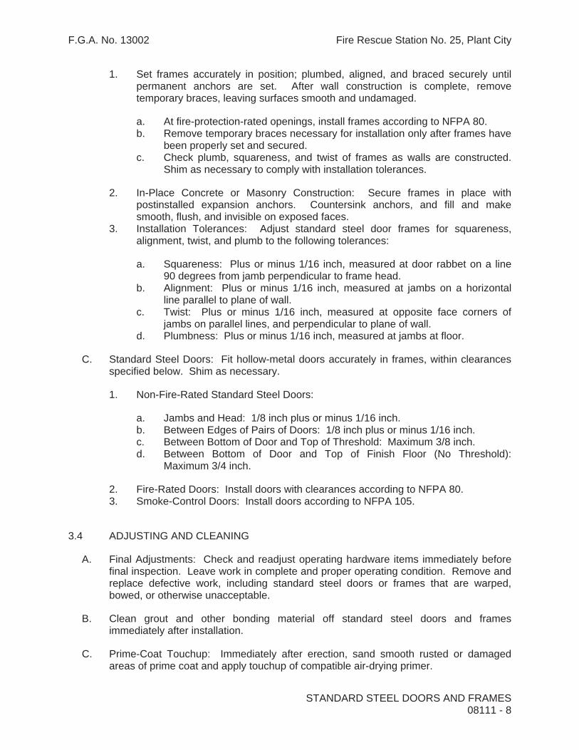
F.G.A. No. 13002 Fire Rescue Station No. 25, Plant City
1. Set frames accurately in position; plumbed, aligned, and braced securely until permanent anchors are set. After wall construction is complete, remove temporary braces, leaving surfaces smooth and undamaged.
a. At fire-protection-rated openings, install frames according to NFPA 80. b. Remove temporary braces necessary for installation only after frames have
been properly set and secured. c. Check plumb, squareness, and twist of frames as walls are constructed.
Shim as necessary to comply with installation tolerances.
2. In-Place Concrete or Masonry Construction: Secure frames in place with postinstalled expansion anchors. Countersink anchors, and fill and make smooth, flush, and invisible on exposed faces.
3. Installation Tolerances: Adjust standard steel door frames for squareness, alignment, twist, and plumb to the following tolerances:
a. Squareness: Plus or minus 1/16 inch, measured at door rabbet on a line 90 degrees from jamb perpendicular to frame head.
b. Alignment: Plus or minus 1/16 inch, measured at jambs on a horizontal line parallel to plane of wall.
c. Twist: Plus or minus 1/16 inch, measured at opposite face corners of jambs on parallel lines, and perpendicular to plane of wall.
d. Plumbness: Plus or minus 1/16 inch, measured at jambs at floor.
C. Standard Steel Doors: Fit hollow-metal doors accurately in frames, within clearances specified below. Shim as necessary.
1. Non-Fire-Rated Standard Steel Doors:
a. Jambs and Head: 1/8 inch plus or minus 1/16 inch. b. Between Edges of Pairs of Doors: 1/8 inch plus or minus 1/16 inch.c. Between Bottom of Door and Top of Threshold: Maximum 3/8 inch. d. Between Bottom of Door and Top of Finish Floor (No Threshold):
Maximum 3/4 inch.
2. Fire-Rated Doors: Install doors with clearances according to NFPA 80. 3. Smoke-Control Doors: Install doors according to NFPA 105.
3.4 ADJUSTING AND CLEANING
A. Final Adjustments: Check and readjust operating hardware items immediately before final inspection. Leave work in complete and proper operating condition. Remove and replace defective work, including standard steel doors or frames that are warped, bowed, or otherwise unacceptable.
B. Clean grout and other bonding material off standard steel doors and frames immediately after installation.
C. Prime-Coat Touchup: Immediately after erection, sand smooth rusted or damaged areas of prime coat and apply touchup of compatible air-drying primer.
STANDARD STEEL DOORS AND FRAMES 08111 - 8

F.G.A. No. 13002 Fire Rescue Station No. 25, Plant City
STANDARD STEEL DOORS AND FRAMES 08111 - 9
D. Galvannealed Surfaces: Clean abraded areas and repair with galvanizing repair paint according to manufacturer's written instructions.
END OF SECTION 08111

F.G.A. No. 13002 Fire Rescue Station No. 25, Plant City
SECTION 08211 - FLUSH WOOD DOORS
PART 1 - GENERAL
1.1 RELATED DOCUMENTS
A. Drawings and general provisions of the Contract, including General and Supplementary Conditions and Division 1 Specification Sections, apply to this Section.
1.2 SUMMARY
A. This Section includes the following:
1. Solid core doors with wood veneer faces. 2. Factory fitting flush wood doors to frames and factory machining for hardware.
B. Related Sections:
1. Division 9 Section “Painting” for field painting of metal louvers and metal frames for light openings.
1.3 SUBMITTALS
A. General: Submit each item in this Article according to the Conditions of the Contract.
B. Product data for each type of door, including details of core and edge construction, trim for openings and louvers, and factory-finishing specifications.
C. Shop drawings indicating location and size of each door, elevation of each kind of door, details of construction, location and extent of hardware blocking, fire ratings, and other pertinent data.
1. For factory-machined doors, indicate dimensions and locations of cutouts for locksets and other cutouts adjacent to light and louver openings.
D. Samples for Initial Selection: Color charts consisting of actual materials in small sections for the following:
1. Faces of Factory-Finished Doors: Show the full range of colors available for stained finishes.
E. Samples for Verification:
1. Factory finishes applied to actual door face materials, approximately 8 by 10 inches, for each material and finish. For each wood species and transparent finish, provide set of three samples showing typical range of color and grain to be expected in the finished work.
FLUSH WOOD DOORS 08211 - 1

F.G.A. No. 13002 Fire Rescue Station No. 25, Plant City
1.4 QUALITY ASSURANCE
A. Quality Standard: Comply with the following standard:
1. AWI Quality Standard: AArchitectural Woodwork Quality Standards@ of the Architectural Woodwork Institute for grade of door, core, construction, finish, and other requirements.
B. Fire-Rated Wood Doors: Provide wood doors that comply with NFPA 80; are identical in materials and construction to units tested in door and frame assemblies per ASTM E 152; and are labeled and listed by UL, Warnock Hersey, or another testing and inspection agency acceptable to authorities having jurisdiction.
C. Single-Source Responsibility: Obtain doors from one source and by a single manufacturer.
1.5 DELIVERY, STORAGE, AND HANDLING
A. Protect doors during transit, storage, and handling to prevent damage, soiling, and deterioration. Comply with requirements of referenced standard and manufacturer's instructions.
B. Identify each door with individual opening numbers as designated on shop drawings, using temporary, removable, or concealed markings.
1.6 PROJECT CONDITIONS
A. Conditioning: Do not deliver or install doors until conditions for temperature and relative humidity have been stabilized and will be maintained in storage and installation areas during the remainder of the construction period to comply with the following requirements applicable to Project's geographical location:
1. AWI quality standard Section 100-S-11 "Relative Humidity and Moisture Content."
1.7 WARRANTY
A. General Warranty: Door manufacturer's warranty specified in this Article shall not deprive the Owner of other rights the Owner may have under other provisions of the Contract Documents and shall be in addition to, and run concurrent with, other warranties made by the Contractor under requirements of the Contract Documents.
B. Door Manufacturer's Warranty: Submit written agreement on door manufacturer's standard form signed by manufacturer, Installer, and Contractor, agreeing to repair or replace defective doors that have warped (bow, cup, or twist) more than 1/4 inch in a 42-by-84-inch section or that show telegraphing of core construction in face veneers exceeding 0.01 inch in a 3-inch span, or do not conform to tolerance limitations of referenced quality standards.
FLUSH WOOD DOORS 08211 - 2

F.G.A. No. 13002 Fire Rescue Station No. 25, Plant City
1. Warranty shall also include installation and finishing that may be required due to repair or replacement of defective doors where defect was not apparent prior to hanging.
2. Warranty shall be in effect during the following period of time after date of Substantial Completion.
a. Solid Core Interior Doors: One year.
PART 2 - PRODUCTS
2.1 MANUFACTURERS
A. Manufacturer: Subject to compliance with requirements, provide doors by one of the following:
1. Solid Core Doors:
a. Algoma Hardwoods, Inc. b. Eggers Industries c. Graham Wood Doors d. Marshfield Door Systems e. Mohawk Flush Doors, Inc. f. VT Industries, Inc.
2.2 INTERIOR FLUSH WOOD DOORS
A. Solid Core Doors for Transparent Finish: Comply with the following requirements:
1. Faces: Running, book-matched, rotary-cut, white birch. 2. A.W.I. Grade: Premium. 3. Construction: PC 5 (Particleboard core, 5 ply, with core bonded to faces). 4. Core: Particleboard core, ANSI A208.1, Grade LD-2. 5. Bonding: Stiles and rails bonded to core, then entire unit abrasive planed before
veneering.
B. Fire-Rated Solid Core Doors: Comply with the following requirements:
1. Faces and Grade: Provide faces and grade to match non-fire-rated doors in same area of building, unless otherwise indicated.
2. Construction: Manufacturer's standard core construction as required to provide fire-resistance rating indicated.
3. Blocking: Provide composite blocking designed to maintain fire resistance of door but with improved screw-holding capability of same thickness as core and with minimum dimensions as follows:
a. 5-inch top rail blocking. b. 5-inch bottom rail blocking. c. 5-by-18-inch lock blocks. d. 5-inch midrail blocking.
FLUSH WOOD DOORS 08211 - 3

F.G.A. No. 13002 Fire Rescue Station No. 25, Plant City
2.3 LOUVERS AND LIGHT FRAMES
A. Metal Louvers:
1. Blade Type: Vision-proof, inverted V. 2. Metal and Finish: Galvanized steel, 0.0396 inch thick, hot-dip zinc coated and
factory primed for paint finish.
B. Fire Door Louvers: Metal louvers with fusible link and closing device, listed and labeled for use in doors with fire rating of one and one-half hours and less.
C. Metal Frames for Light Openings: Manufacturer’s standard frame formed of 0.0478-inch thick, cold-rolled steel sheet; factory primed and approved for use in doors including fire rated doors where indicated.
2.4 FABRICATION
A. Fabricate flush wood doors to comply with following requirements:
1. Factory fit doors to suit frame-opening sizes indicated, with the following uniform clearances and bevels:
a. Comply with clearance requirements of referenced quality standard for fitting.
b. Comply with requirements of NFPA 80 for fire-resistance-rated doors.
2. Factory machine doors for hardware that is not surface applied. Locate hardware to comply with DHI-WDHS-3. Comply with final hardware schedules, door frame shop drawings, DHI A115-W series standards, and hardware templates.
a. Coordinate measurements of hardware mortises in metal frames to verify dimensions and alignment before proceeding with factory machining.
B. Openings: Cut and trim openings through doors to comply with applicable requirements of referenced standards for kind(s) of door(s) required.
2.5 FACTORY FINISHING
A. General: Comply with AWI’s “Architectural Woodwork Quality Standards Illustrated” for factory finishing.
B. Finish doors at factory.
C. Transparent Finish:
1. Grade: Premium 2. Finish: AWI System TR-6 catalyzed polyurethane. 3. Staining: As selected by Architect from manufacturer’s full range.
FLUSH WOOD DOORS 08211 - 4

F.G.A. No. 13002 Fire Rescue Station No. 25, Plant City
FLUSH WOOD DOORS 08211 - 5
4. Sheen: Satin
PART 3 - EXECUTION
3.1 EXAMINATION
A. Examine installed door frames prior to hanging door:
1. Verify that frames comply with indicated requirements for type, size, location, and swing characteristics and have been installed with plumb jambs and level heads.
2. Reject doors with defects.
B. Do not proceed with installation until unsatisfactory conditions have been corrected.
3.2 INSTALLATION
A. Hardware: For installation see Division 8 Section "Door Hardware."
B. Manufacturer's Instructions: Install wood doors to comply with manufacturer's instructions and referenced quality standard and as indicated.
1. Install fire-rated doors in corresponding fire-rated frames according to requirements of NFPA 80.
2. Fitting Clearances for Non-Fire-Rated Doors: Provide 1/8 inch at jambs and heads, 1/16 inch per leaf at meeting stiles for pairs of doors, and 1/8 inch from bottom of door to top of decorative floor finish or covering. Where threshold is shown or scheduled, provide 1/4-inch clearance from bottom of door to top of threshold.
3. Fitting Clearances for Fire-Rated Doors: Comply with NFPA 80.
C. Factory-Fitted Doors: Align in frames for uniform clearance at each edge.
3.3 ADJUSTING AND PROTECTION
A. Operation: Rehang or replace doors that do not swing or operate freely.
B. Finished Doors: Refinish or replace doors damaged during installation.
C. Protect doors as recommended by door manufacturer to ensure that wood doors will be without damage or deterioration at the time of Substantial Completion.
END OF SECTION 08211

F.G.A. No. 13002 Fire Rescue Station No. 25, Plant City
SECTIONAL OVERHEAD DOORS 08361 - 1
SECTION 08361 - SECTIONAL OVERHEAD DOORS
PART 1 - GENERAL
1.1 RELATED DOCUMENTS
A. Drawings and general provisions of the Contract, including General and Supplementary Conditions and Division 1 Specification Sections, apply to this Section.
1.2 SUMMARY
A. This Section includes sectional overhead doors, as follows:
1. Steel panel doors.
B. Related Sections include the following:
1. Division 9, Section “Painting” for field-applied paint finish on exterior sides of doors.
1.3 SUBMITTALS
A. General: Submit the following according to Conditions of the Contract.
B. Product data, roughing-in diagrams, and installation instructions for each type and size of overhead door. Include manufacturer's operating instructions and maintenance data.
C. Shop drawings for special components and installations which are not fully dimensioned or detailed in manufacturer's data including wind bracing for door panels.
1. Drawings must include details for anchorage of door tracks to building to meet wind and impact load requirements. Indicate fastener or weld type, size, and spacing for attachment to masonry walls. Note actual, field-measured rough door opening dimensions.
2. Shop drawings shall be signed and sealed by a Florida registered professional engineer.
3. Shop Drawings shall include State of Florida Product Approval.
a. Approval must be applicable to actual door size specified herein.
1.4 QUALITY ASSURANCE
A. Manufacturer Qualifications: Provide each sectional overhead door as a complete unit produced by a single manufacturer, including frames, sections, brackets, guides, tracks, counterbalance mechanisms, hardware, and installation accessories.
B. Installer: Installation of sectional doors shall be performed by an authorized representative

F.G.A. No. 13002 Fire Rescue Station No. 25, Plant City
SECTIONAL OVERHEAD DOORS 08361 - 2
of the manufacturer.
C. Single-Source Responsibility: Provide doors, tracks, and accessories from one manufacturer. Provide secondary components from source acceptable to manufacturer of primary components.
D. Pre-Installation Conference: Schedule and convene a pre-installation conference just prior to commencement of field operations, to establish procedures to maintain optimum working conditions and to coordinate this work with related and adjacent work.
E. Wind Loads: Provide sectional overhead door system including anchorage to building capable of withstanding wind load design pressures as indicated:
1. Positive pressure = 50 p.s.f. 2. Negative pressure = -50 p.s.f.
F. Missile Impact Loads: Provide sectional overhead door system including anchorage to building capable of withstanding large and small missile impact loads in accordance with the Florida Building Code, Sections 1609 and 1626.
PART 2 - PRODUCTS
2.1 ACCEPTABLE MANUFACTURERS
A. Manufacturers: Subject to compliance with requirements provide one of the following:
1. Overhead Door Corporation – Series 424 Commercial Steel Door. 2. Raynor Garage Doors – Series S24 SteelForm Standard Steel Door. 3. Clopay Building Products – Series 524 Commercial Sectional Door. 4. Substitutions: Equivalent products by other manufacturers will be considered upon
receipt of a properly submitted substitution request not less than 10 days prior to bid opening. Such requests must be accompanied by a copy of a shop drawing reflecting State of Florida Product Approval and compliance with wind load pressures as noted above for the specified door size.
2.2 STEEL SECTIONS
A. Sectional Door Assembly: Steel door assembly with rabbeted meeting rails to form weathertight joints and provide full-width interlocking structural rigidity. Units shall have the following characteristics:
1. Panel Thickness: 2”. 2. Exterior Surface: Smooth Rib. 3. Steel: Minimum 24 gauge, galvanized. 4. Center and End Stiles: 16 gauge. 5. Finish and Color: Factory-applied baked-on white polyester or epoxy coating. 6. Height: 14’-1” (required for 14’-0” actual, clear masonry opening).

F.G.A. No. 13002 Fire Rescue Station No. 25, Plant City
SECTIONAL OVERHEAD DOORS 08361 - 3
7. Width: 14’-2” (required for 14’-0” actual, clear masonry opening). Door must be wide enough to allow tracks’ continuous angles to be secured to reinforced concrete columns as indicated on drawings.
B. Reinforce sections with continuous horizontal reinforcing, as required by door width and design wind loading. Provide galvanized steel angles, bars, struts, channels, or U-bars, formed to depth, and bolted in place.
2.3 TRACKS, SUPPORTS, AND ACCESSORIES
A. Tracks: Provide manufacturer's standard, 3” galvanized-steel track system designed for clearances shown. Provide complete track assembly including brackets, bracing and reinforcing for rigid support of ball-bearing roller guides for required door type and size. Slope tracks at proper angle from vertical, or otherwise design to ensure tight closure at jambs when door unit is closed. Weld or bolt to track supports.
1. Provide lift clearance track.
B. Track Reinforcement and Supports: Provide galvanized-steel track reinforcement and support members. Secure, reinforce and support tracks as required for size and weight of door to provide strength and rigidity without sag, sway, and vibration during opening and closing of doors.
C. Support and attach tracks to opening jambs with continuous angle welded to tracks and attached to wall. Support horizontal (ceiling tracks) with continuous angle welded to track and supported by laterally braced attachments to overhead structural members at curve, mid-point, and end of tracks.
D. Weather Seals: Provide continuous rubber, neoprene, or flexible vinyl adjustable weatherstrip gasket at tops and compressible astragal on bottoms of each overhead door. Provide jamb seals.
2.4 HARDWARE
A. General: Provide heavy-duty, rust-resistant hardware, with galvanized or cadmium-plated or stainless steel fasteners, to suit type of door.
B. Hinges: Provide heavy steel hinges at each end stile and at each intermediate stile, per manufacturer's recommendations for size of door. Attach hinges to door sections through stiles and rails with bolts and lock nuts or lock washers and nuts. Use rivets or self-tapping fasteners where access to nuts is not possible.
C. Rollers: Provide heavy-duty rollers, with steel ball bearings in case-hardened steel races, mounted with varying projections to suit slope of track. Extend roller shaft through both hinges where double hinges are required. Provide roller tires to suit size of track (3-inch diameter for 3-inch track) and as follows:
1. Case-hardened steel tires for normal installations.

F.G.A. No. 13002 Fire Rescue Station No. 25, Plant City
SECTIONAL OVERHEAD DOORS 08361 - 4
2.5 COUNTERBALANCING MECHANISM
A. Torsion Spring: Operation by torsion-spring counterbalance mechanism, consisting of heavy duty adjustable-tension, tempered-steel torsion springs mounted on a cross header tube or steel shaft. Connect to door with galvanized aircraft-type lift cables. Provide springs calibrated for 100,000 cycles minimum.
B. Provide cast-aluminum or grey-iron casting cable drums, grooved to receive cable. Mount counterbalance mechanism with manufacturer's standard ball-bearing brackets at each end of shaft. Provide one additional midpoint bracket for shafts up to 16 feet long and two additional brackets at one-third points to support shafts over 16 feet long, unless closer spacing recommended by door manufacturer.
C. Provide a spring bumper at each horizontal track to cushion door at end of opening operation.
2.6 ELECTRIC DOOR OPERATORS
A. General: Furnish electric door-operator assembly of size and capacity recommended and provided by door manufacturer; complete with electric motor and factory-prewired motor controls, starter, gear-reduction unit, solenoid-operated brake, clutch, remote-control stations, control devices, integral gearing for locking door, and accessories required for proper operation.
B. Disconnect Device: Hand-operated disconnect device or mechanism for automatically engaging chain-and-sprocket operator and releasing brake for emergency manual operation while disconnecting motor without affecting timing of limit switch. Mount emergency chain operator so it is accessible from floor level. Include interlock device to automatically prevent motor from operating when emergency operator is engaged.
C. Design operator so that motor may be removed without disturbing limit-switch adjustment and without affecting emergency auxiliary operator.
D. Provide 6 digit, non-resettable counter mounted to each operator.
E. Door Operator Type: Provide the following:
1. Jackshaft (side mount) gear-head hoist type, with enclosed worm-gear, running-in-oil, primary drive; chain-and-sprocket secondary drive; auxiliary chain hoist; and floor-level quick release for manual operation.
a. Product: Provide Liftmaster Model GH 75 operator (no substitutions).
F. Electric Motors: Provide high-starting torque, reversible, constant-duty, Class A-insulated electric motors with overload protection, sized to move door in either direction, from any position, at not less than 2/3 foot per second or more than 1 foot per second.

F.G.A. No. 13002 Fire Rescue Station No. 25, Plant City
SECTIONAL OVERHEAD DOORS 08361 - 5
1. Coordinate wiring requirements and current characteristics of motors with building electrical system.
2. Provide open-drip-proof type motor, and controller with NEMA ICS 6, Type 1 enclosure.
3. Motor to be minimum ¾ H.P.
G. Remote Control Station: Provide momentary-contact, three-button control station with push button controls labeled “Open”, “Close”, and “Stop”.
1. Provide interior units, full-guarded, surface-mounted, heavy-duty, with general purpose NEMA Type 1 enclosure, two per door as indicated on drawings (two gangs of six stations each).
H. Radio control system: Provide universal radio control system. Provide one UHF radio receiver for each door operator. Provide four six-channel portable transmitters. Program transmitters in accordance with Owner’s directions at time of installation.
1. Provide one coaxial antenna per door installed below soffit and centered on door opening with stainless steel brackets, as indicated on drawings.
I. Automatic Reversing Control: Provide each door with automatic safety sensor edge, located within neoprene or rubber astragal mounted to bottom door bar. Contact with bar shall immediately reverse downward door travel. Provide manufacturer’s standard take-up reel or self-coiling cable.
1. Provide electrically or pneumatically actuated automatic bottom bar.
J. Photoelectric Sensor: Provide each door with the following:
1. In addition to automatic bottom bar, provide watertight NEMA 4 design photoelectric system designed to detect an obstruction in door opening without contact between door and obstruction. Photoelectric system components shall be positioned to create a diagonal beam across each door opening. Verify mounting height with Architect prior to installation.
K. Door Open Indicator Lights: Coordinate installation of electric door operators with installation of wall-mounted “fully open” indicator lights as shown on drawings.
PART 3 – EXECUTION
3.1 INSTALLATION
A. General: Install doors, tracks, and operating equipment complete with necessary hardware, jamb and head mold stops, anchors, inserts, hangers, and equipment supports according to shop drawings, manufacturer's instructions, and as specified.
B. Fasten vertical track assembly to structure in accordance with shop drawings. Hang horizontal track from structural overhead framing with angle or channel hangers, bolt-

F.G.A. No. 13002 Fire Rescue Station No. 25, Plant City
SECTIONAL OVERHEAD DOORS 08361 - 6
fastened in place. Provide sway bracing, diagonal bracing, and reinforcing as required for rigid installation of track and door-operating equipment.
C. After completing installation, including work by other trades, lubricate, test, and adjust doors to operate easily, free from warp, twist, or distortion and fitting weathertight for entire perimeter.
D. Touch-up damaged coatings, finishes, and repair minor damage. Clean exposed surfaces using non-abrasive materials and methods recommended by manufacturer of material or product being cleaned.
3.3 DEMONSTRATION
A. Startup Services: Engage a factory-authorized service representative to perform startup services and to train Owner’s maintenance personnel as specified below:
1. Test and adjust controls and safeties. Replace damaged and malfunctioning controls and equipment.
2. Train Owner’s maintenance personnel on procedures and schedules related to startup and shutdown, troubleshooting, servicing, and preventative maintenance.
3. Review data in the maintenance manuals. 4. Schedule training with Owner with at least 7 days’ advance notice.
END OF SECTION 08361

F.G.A. No. 13002 Fire Rescue Station No. 25, Plant City
SECTION 08410 - ALUMINUM ENTRANCES AND STOREFRONTS
PART 1 - GENERAL
1.1 RELATED DOCUMENTS
A. Drawings and general provisions of the Contract, including General and Supplementary Conditions and Division 1 Specification Sections, apply to this Section.
1.2 SUMMARY
A. This Section includes the following:
1. Exterior entrance systems (hurricane-resistant). 2. Exterior storefront systems.
B. Related sections include the following:
1. Division 7 Section “Joint Sealants” for sealing between framing and masonry. 2. Division 8 Section “Door Hardware” for lock cylinders.
1.3 SYSTEM DESCRIPTION
A. General: Provide aluminum entrance and storefront systems capable of withstanding loads and thermal and structural movement requirements indicated without failure, based on testing manufacturer's standard units in assemblies similar to those indicated for this Project. Failure includes the following:
1. Air infiltration and water penetration exceeding specified limits. 2. Framing members transferring stresses, including those caused by thermal and
structural movement, to glazing units.
B. Glazing: Physically and thermally isolate glazing from framing members.
C. Wind Loads: Provide entrance and storefront systems, including anchorage, capable of withstanding wind-load design pressures calculated according to the requirements of the Florida Building Code and ASCE 7-10.
1. Positive Minimum Allowable Design Wind Pressure = +30 psf 2. Negative Minimum Allowable Design Wind Pressure = -32.6 psf 3. Deflection of framing members in a direction normal to wall plane is limited to
1/175 of clear span or 3/4 inch, whichever is smaller, unless otherwise indicated. 4. Static-Pressure Test Performance: Provide entrance and storefront systems that do
not evidence material failures, structural distress, failure of operating components to function normally, or permanent deformation of main framing members exceeding 0.2 percent of clear span when tested according to ASTM E 330.
ALUMINUM ENTRANCES AND STOREFRONTS 08410 - 1

F.G.A. No. 13002 Fire Rescue Station No. 25, Plant City
a. Test Pressure: 150 percent of inward and outward wind-load design pressures.
b. Duration: As required by design wind velocity; fastest 1 mile of wind for relevant exposure category.
D. Hurricane-Resistance Test Performance: Provide entrance and storefront systems that pass large and small missile-impact tests, as required by systems’ location above grade, and cyclic-pressure tests according to The Florida Building Code, Sections 1606 and 1626.
E. Dead Loads: Provide entrance- and storefront-system members that do not deflect an amount which will reduce glazing bite below 75 percent of design dimension when carrying full dead load.
1. Provide a minimum 1/8-inch clearance between members and top of glazing or other fixed part immediately below.
2. Provide a minimum 1/16-inch clearance between members and operable windows and doors.
F. Live Loads: Provide entrance and storefront systems, including anchorage, that accommodate the supporting structures' deflection from uniformly distributed and concentrated live loads indicated without failure of materials or permanent deformation.
G. Engineering Responsibility: Storefront subcontractor shall engage a Florida registered structural engineer to design connections, member reinforcements, and fastening to building structure, and prepare design calculations and engineering data.
H. Air Infiltration: Provide entrance and storefront systems with permanent resistance to air leakage through fixed glazing and frame areas of not more than 0.06 cfm/sq. ft. of fixed wall area when tested according to ASTM E 283 at a static-air-pressure difference of 1.57 lbf/sq. ft
I. Water Penetration: Provide entrance and storefront systems that do not evidence water leakage through fixed glazing and frame areas when tested according to ASTM E 331 at minimum differential pressure of 20 percent of inward-acting wind-load design pressure as defined by ASCE 7, "Minimum Design Loads for Buildings and Other Structures," but not less than 6.24 lbf/sq. ft. Water leakage is defined as follows:
1. Uncontrolled water infiltrating systems or appearing on systems' normally exposed interior surfaces from sources other than condensation. Water controlled by flashing and gutters that is drained back to the exterior and cannot damage adjacent materials or finishes is not water leakage.
J. Thermal Movements: Provide entrance and storefront systems, including anchorage, that accommodate thermal movements of systems and supporting elements resulting from the following maximum change (range) in ambient and surface temperatures without buckling, damaging stresses on glazing, failure of joint sealants, damaging loads on fasteners, failure of doors or other operating units to function properly, and other detrimental effects.
1. Temperature Change (Range): 100 deg F ambient; 150 deg F material surfaces.
ALUMINUM ENTRANCES AND STOREFRONTS 08410 - 2

F.G.A. No. 13002 Fire Rescue Station No. 25, Plant City
K. Structural-Support Movement: Provide entrance and storefront systems that accommodate structural movements including, but not limited to, sway and deflection.
L. Dimensional Tolerances: Provide entrance and storefront systems that accommodate dimensional tolerances of building frame and other adjacent construction.
1.4 SUBMITTALS
A. Product Data: For each product specified. Include details of construction relative to materials, dimensions of individual components, profiles, and finishes.
B. Shop Drawings: For entrance and storefront systems. Show details of fabrication and installation, including plans, elevations, sections, details of components, provisions for expansion and contraction, and attachments to other work. Show elevations at 2 A scale and details at 3" scale.
1. Shop drawings shall include large-scale anchorage details indicating attachment to slabs, walls, and overhead structure.
2. Submit calculations, structural properties, connection information and product information to verify that the system performance and anchorage can successfully resist wind loads. All calculations shall be signed and sealed by a Florida registered professional structural engineer.
3. For entrance systems, include hardware schedule and indicate operating hardware types, quantities, and locations.
4. Shop drawings shall include State of Florida Product Approval applicable to actual sizes of doors indicated.
1.5 QUALITY ASSURANCE
A. Installer Qualifications: Engage an experienced installer to assume engineering responsibility and perform work of this Section who has specialized in installing entrance and storefront systems similar to those required for this Project and who is acceptable to manufacturer.
1. Engineering Responsibility: Prepare data for entrance and storefront systems, including Shop Drawings, based on testing and engineering analysis of manufacturer's standard units in assemblies similar to those indicated for this Project.
B. Source Limitations: Obtain each type of entrance and storefront system through one source from a single manufacturer.
C. Product Options: Drawings indicate size, profiles, and dimensional requirements of entrance and storefront systems and are based on the specific systems indicated.
1. Do not modify intended aesthetic effect, as judged solely by Architect, except with Architect's approval and only to the extent needed to comply with performance requirements. Where modifications are proposed, submit comprehensive
ALUMINUM ENTRANCES AND STOREFRONTS 08410 - 3

F.G.A. No. 13002 Fire Rescue Station No. 25, Plant City
explanatory data to Architect for review.
1.6 PROJECT CONDITIONS
A. Field Measurements: Verify dimensions by field measurements before fabrication and indicate measurements on Shop Drawings. Coordinate fabrication schedule with construction progress to avoid delaying the Work.
PART 2 - PRODUCTS
2.1 MANUFACTURERS
A. Manufacturers: Subject to compliance with requirements, provide products by one of the following:
1. Kawneer Company, Inc. 2. Vistawall Architectural Products. 3. YKK AP America
2.2 MATERIALS
A. Aluminum: Alloy and temper recommended by manufacturer for type of use and finish indicated, complying with the requirements of standards indicated below.
1. Sheet and Plate: ASTM B 209. 2. Extruded Bars, Rods, Shapes, and Tubes: ASTM B 221. 3. Extruded Structural Pipe and Tubes: ASTM B 429. 4. Bars, Rods, and Wire: ASTM B 211.
B. Steel Reinforcement: Complying with ASTM A 36 for structural shapes, plates, and bars; ASTM A 611 for cold-rolled sheet and strip; or ASTM A 570 for hot-rolled sheet and strip.
C. Glazing shall be provided by aluminum entrance manufacturer as follows:
1. Glass must be laminated glass product of the type included in the entrance assembly that was tested for hurricane resistance.
2. Glass shall be 9/16” thick consisting of a ¼” thick, fully tempered outer lite of Pilkington LOF “Evergreen” glass, a .090” thick PVB plastic interlayer, and a ¼” thick, fully tempered inner lite of clear glass.
D. Glazing Gaskets: Manufacturer's standard pressure-glazing system of black, resilient glazing gaskets, setting blocks, and shims or spacers, fabricated from an elastomer of type and in hardness recommended by system and gasket manufacturer to comply with system performance requirements. Provide gasket assemblies that have corners sealed with sealant recommended by gasket manufacturer.
ALUMINUM ENTRANCES AND STOREFRONTS 08410 - 4

F.G.A. No. 13002 Fire Rescue Station No. 25, Plant City
1. Provide silicone sealant in lieu of glazing gasket if required by entrance manufacturer for hurricane-resistant construction.
E. Framing system gaskets, sealants, and joint fillers as recommended by manufacturer for joint type.
2.3 COMPONENTS
A. Doors: Provide manufacturer's standard 1-3/4-inch- thick glazed doors with minimum 0.125-inch- thick, extruded tubular rail and stile members. Mechanically fasten corners with reinforcing brackets that are deep penetration and fillet welded or that incorporate concealed tie-rods.
1. Glazing Stops and Gaskets: Provide manufacturer's standard snap-on extruded-aluminum glazing stops and preformed gaskets.
2. Stile Design: Medium stile; 3-1/2-inch nominal width.
B. Brackets and Reinforcements: Provide manufacturer's standard brackets and reinforcements that are compatible with adjacent materials. Provide nonstaining, nonferrous shims for aligning system components.
C. Fasteners and Accessories: Manufacturer's standard corrosion-resistant, nonstaining, nonbleeding fasteners and accessories compatible with adjacent materials.
1. Reinforce members as required to retain fastener threads. 2. Do not use exposed fasteners, except for hardware application. For hardware
application, use countersunk Phillips flat-head machine screws finished to match framing members or hardware being fastened, unless otherwise indicated.
D. Weather Stripping: Manufacturer's standard replaceable weather stripping as follows:
1. Compression Weather Stripping: Molded neoprene complying with ASTM D 2000 requirements or molded PVC complying with ASTM D 2287 requirements.
2. Sliding Weather Stripping: Wool, polypropylene, or nylon woven pile with nylon-fabric or aluminum-strip backing complying with AAMA 701 requirements.
2.4 HARDWARE
A. General: Provide heavy-duty hardware units indicated in sizes, number, and type recommended by manufacturer for entrances indicated.
B. Ball-Bearing Butts: ANSI/BHMA A156.1, Grade 1, 5 knuckle, 4 1/2-by4-inch ball-bearing butts. Provide nonremovable pins at hinges exposed to door outside and provide nonferrous hinges for applications exposed to weather. Provide 3 hinges at each leaf for doors up to 36 inches wide and 80 inches tall; provide 4 hinges at each leaf for taller doors.
C. Closers, General: Comply with manufacturer's recommendations for closer size,
ALUMINUM ENTRANCES AND STOREFRONTS 08410 - 5

F.G.A. No. 13002 Fire Rescue Station No. 25, Plant City
depending on door size, exposure to weather, and anticipated frequency of use.
1. Closing Cycle: Comply with Florida Accessibility code for Building construction or the Americans with Disabilities Act (ADA), whichever is more stringent.
2. Opening Force: Comply with the following maximum opening-force requirements for locations indicated:
a. Exterior Doors: 8.5 lbf.
3. Hold Open: Adjustable.
D. Surface-Mounted Overhead Closers: ANSI/BHMA A156.4, Grade 1.
E. Door Stops: ANSI/BHMA A156.16, Grade 1, floor- or wall-mounted door stop, as appropriate for door location indicated, with integral rubber bumper.
F. Mortise Cylinders: Cylinders are specified in Section 08710 - Door Hardware.
G. Deadlatch Locks: Manufacturer=s standard mortise deadlatch with minimum 2 inch long latch bolt and auxiliary bolt located below latch bolt and complying with ANSI/BHMA A156.5, Grade 1 requirements.
H. Radius Face Strikes: Manufacturer's standard stainless-steel, radiused face strike with steel mounting plate and black-plastic dustbox.
I. Vertical-Rod Exit Devices: At all doors, provide concealed, vertical-rod exit device complying with UL 305 requirements, with 2-point top and bottom latching that is released by a full-width crash bar or when locked down (dogged) by lock cylinder or retracting screws beneath housing.
1. Device shall comply with hurricane-resistant entrance system requirements.
J. Pull Handles: As selected by Architect from manufacturer’s full range of pull handles and plates.
K. Thresholds: At exterior doors, provide manufacturer's standard threshold with cutouts coordinated for operating hardware, with anchors and jamb clips, and not more than 2-inch- high, with beveled edges providing a floor level change with a slope of not more than 1:2, and in the following material:
1. Material: Aluminum, mill finish.
L. Weather Sweeps: Manufacturer's standard weather sweep for application to exterior door bottoms and with concealed fasteners on mounting strips.
2.5 FABRICATION
A. General: Fabricate components that, when assembled, will have accurately fitted joints with ends coped or mitered to produce hairline joints free of burrs and distortion. After fabrication, clearly mark components to identify their locations in Project according to Shop
ALUMINUM ENTRANCES AND STOREFRONTS 08410 - 6
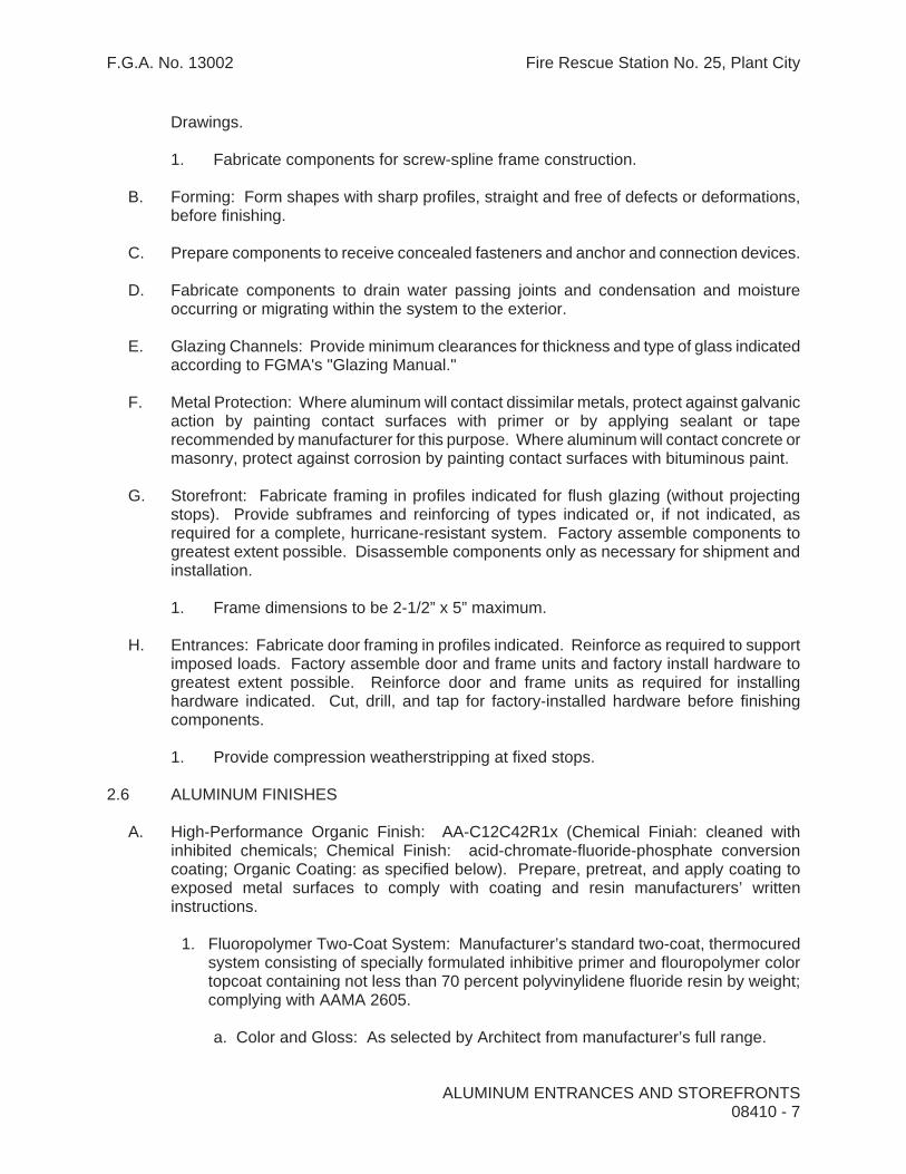
F.G.A. No. 13002 Fire Rescue Station No. 25, Plant City
Drawings.
1. Fabricate components for screw-spline frame construction.
B. Forming: Form shapes with sharp profiles, straight and free of defects or deformations, before finishing.
C. Prepare components to receive concealed fasteners and anchor and connection devices.
D. Fabricate components to drain water passing joints and condensation and moisture occurring or migrating within the system to the exterior.
E. Glazing Channels: Provide minimum clearances for thickness and type of glass indicated according to FGMA's "Glazing Manual."
F. Metal Protection: Where aluminum will contact dissimilar metals, protect against galvanic action by painting contact surfaces with primer or by applying sealant or tape recommended by manufacturer for this purpose. Where aluminum will contact concrete or masonry, protect against corrosion by painting contact surfaces with bituminous paint.
G. Storefront: Fabricate framing in profiles indicated for flush glazing (without projecting stops). Provide subframes and reinforcing of types indicated or, if not indicated, as required for a complete, hurricane-resistant system. Factory assemble components to greatest extent possible. Disassemble components only as necessary for shipment and installation.
1. Frame dimensions to be 2-1/2” x 5” maximum.
H. Entrances: Fabricate door framing in profiles indicated. Reinforce as required to support imposed loads. Factory assemble door and frame units and factory install hardware to greatest extent possible. Reinforce door and frame units as required for installing hardware indicated. Cut, drill, and tap for factory-installed hardware before finishing components.
1. Provide compression weatherstripping at fixed stops.
2.6 ALUMINUM FINISHES
A. High-Performance Organic Finish: AA-C12C42R1x (Chemical Finiah: cleaned with inhibited chemicals; Chemical Finish: acid-chromate-fluoride-phosphate conversion coating; Organic Coating: as specified below). Prepare, pretreat, and apply coating to exposed metal surfaces to comply with coating and resin manufacturers’ written instructions.
1. Fluoropolymer Two-Coat System: Manufacturer’s standard two-coat, thermocured system consisting of specially formulated inhibitive primer and flouropolymer color topcoat containing not less than 70 percent polyvinylidene fluoride resin by weight; complying with AAMA 2605.
a. Color and Gloss: As selected by Architect from manufacturer’s full range.
ALUMINUM ENTRANCES AND STOREFRONTS 08410 - 7

F.G.A. No. 13002 Fire Rescue Station No. 25, Plant City
2.7 STEEL PRIMING FOR STEEL REINFORCEMENT
H. General: Comply with NAAMM's "Metal Finishes Manual for Architectural and Metal Products" for recommendations relative to applying primer.
I. Surface Preparation: Perform manufacturer's standard cleaning operations to remove dirt, oil, grease, or other contaminants that could impair paint bond. Remove mill scale and rust, if present, from uncoated steel.
J. Priming: Apply manufacturer's standard corrosion-resistant primer immediately after surface preparation and pretreatment.
PART 3 - EXECUTION
3.1 EXAMINATION
A. Examine areas, with Installer present, for compliance with requirements for installation tolerances and other conditions affecting performance of entrance and storefront systems. Do not proceed with installation until unsatisfactory conditions have been corrected.
3.2 STOREFRONT INSTALLATION
A. General: Comply with manufacturer's written instructions for protecting, handling, and installing entrance and storefront systems. Do not install damaged components. Fit frame joints to produce hairline joints free of burrs and distortion. Rigidly secure nonmovement joints. Seal joints watertight.
B. Metal Protection: Where aluminum will contact dissimilar metals, protect against galvanic action by painting contact surfaces with primer or by applying sealant or tape recommended by manufacturer for this purpose. Where aluminum will contact concrete or masonry, protect against corrosion by painting contact surfaces with bituminous paint.
C. Install components to drain water passing joints and condensation and moisture occurring or migrating within the system to the exterior.
D. Set continuous sill members and flashing in a full sealant bed to provide weathertight construction, unless otherwise indicated.
E. Install framing components plumb and true in alignment with established lines and grades without warp or rack of framing members.
F. Install entrances plumb and true in alignment with established lines and grades without warp or rack. Lubricate operating hardware and other moving parts according to hardware manufacturers' written instructions.
1. Install surface-mounted hardware according to manufacturer=s written instructions using concealed fasteners to greatest extent possible.
ALUMINUM ENTRANCES AND STOREFRONTS 08410 - 8

F.G.A. No. 13002 Fire Rescue Station No. 25, Plant City
ALUMINUM ENTRANCES AND STOREFRONTS 08410 - 9
G. Install glazing to comply with requirements of Division 8 Section "Glazing," unless otherwise indicated.
H. Install perimeter sealant, using compatible backer rod where indicated on drawings.
I. Erection Tolerances: Install entrance and storefront systems to comply with the following maximum tolerances:
1. Variation from Plane: Limit variation from plane or location shown to 1/8 inch in 12 feet; 1/4 inch over total length.
2. Alignment: Where surfaces abut in line, limit offset from true alignment to 1/16 inch. Where surfaces meet at corners, limit offset from true alignment to 1/32 inch.
3. Diagonal Measurements: Limit difference between diagonal measurements to 1/8 inch.
3.3 ADJUSTING AND CLEANING
A. Adjust doors and hardware to provide tight fit at contact points and weather stripping, smooth operation, and weathertight closure.
B. Remove excess sealant and glazing compounds, and dirt from surfaces.
3.4 PROTECTION
1. Provide final protection and maintain conditions, in a manner acceptable to manufacturer and Installer, that ensure entrance and storefront systems are without damage or deterioration at the time of Substantial Completion.
END OF SECTION 08410

F.G.A. No. 13002 Fire Rescue Station No. 25, Plant City
ALUMINUM WINDOWS 08520-1
SECTION 08520 - ALUMINUM WINDOWS
PART 1 - GENERAL
1.1 RELATED DOCUMENTS
A. Drawings and general provisions of the Contract, including General and Supplementary Conditions and Division 1 Specification Sections, apply to this Section.
1.2 SUMMARY
A. This Section includes Heavy-Commercial Grade aluminum windows of the performance class indicated. Window types required include the following:
1. Horizontal sliding windows.
B. Related Sections include the following: Division 8 Section “Glazing” for glazing requirements for aluminum windows, including those specified to be factory glazed. Refer to drawings for hurricane panels required at each window.
1.3 DEFINITIONS
A. Performance class number, included as part of the window designation system, is the actual design pressure in pounds force per square foot (pascals) used to determine structural test pressure and water test pressure.
1. Structural test pressure, wind load test, is equivalent to 150 percent of the design pressure.
2. Water-leakage-resistance test pressure is equivalent to 15 percent of the design pressure with 2.86 lbf/sq. ft. (137 Pa) as a minimum for Residential, Commercial, and Heavy-Commercial Grade windows.
1.4 PERFORMANCE REQUIREMENTS
A. General: Provide aluminum windows engineered, fabricated, and installed to withstand normal thermal movement, wind loading, and impact loading without failure, as demonstrated by testing manufacturer's standard window assemblies representing types, grades, classes, and sizes required for Project according to test methods indicated.
B. Test Criteria: Testing shall be performed by a qualified independent testing agency based on the following criteria:
1. Refer to structural drawings for table of positive and negative design wind pressures for doors and windows.

F.G.A. No. 13002 Fire Rescue Station No. 25, Plant City
ALUMINUM WINDOWS 08520-2
2. Test Procedures: Test window units according to ASTM E 283 for air infiltration, both ASTM E 331 and ASTM E 547 for water penetration, and ASTM E 330 for structural performance.
C. Performance Requirements: Testing shall demonstrate compliance with requirements indicated in AAMA 101 for air infiltration, water penetration, and structural performance for type, grade, and performance class of window units required. Where required design pressure exceeds the minimum for the specified window grade, comply with requirements of AAMA 101, Section 3, "Optional Performance Classes," for higher than minimum performance class.
1. Air-Infiltration Rate for Operating Units: Not more than 0.19 cfm/ft. of operable sash joint for an inward test pressure of 1.57 lbf/sq. ft.
2. Water Penetration: No water penetration as defined in the test method at an inward test pressure of 15 percent of the design pressure.
3. Structural Performance: No failure or permanent deflection in excess of 0.4 percent of any member's span after removing the imposed load, for positive (inward) and negative (outward) test pressures indicated on drawings.
4. Thermal Movements: Provide window units that allow thermal movement resulting from the following maximum change (range) in ambient temperature when engineering, fabricating, and installing aluminum windows to prevent buckling, opening of joints, and overstressing of components, connections, and other detrimental effects. Base engineering calculation on actual surface temperatures of materials due to solar heat gain and nighttime sky heat loss.
a. Temperature Change (Range): 120 deg F, ambient; 180 deg F material surfaces.
D. Wind Loads: Provide aluminum window system including anchorage to building capable of withstanding minimum allowable wind load design pressures as indicated:
1. Positive pressure = +31.6 psf 2. Negative pressure = -42.3 psf
1.5 SUBMITTALS
A. General: Submit each item in this Article according to the Conditions of the Contract and Division 1 Specification Sections.
B. Product Data for each type of window required, including the following:
1. Construction details and fabrication methods. 2. Profiles and dimensions of individual components. 3. Data on hardware, accessories, and finishes. 4. Recommendations for maintaining and cleaning exterior surfaces.
C. Shop Drawings showing fabrication and installation of each type of window required including information not fully detailed in manufacturer's standard Product Data and the following:

F.G.A. No. 13002 Fire Rescue Station No. 25, Plant City
ALUMINUM WINDOWS 08520-3
1. Layout and installation details, including anchors. 2. Elevations at 1/4 inch = 1 foot scale and typical window unit elevations at 3/4 inch =
1 foot scale. 3. Full-size section details of typical composite members, including reinforcement and
stiffeners.4. Location of weep holes. 5. Panning details. 6. Hardware, including operators. 7. Glazing details. 8. Accessories. 9. Anchorage details at head, jamb, and sill.
D. Samples for initial color selection on 12-inch- long sections of window members. Where finishes involve normal color variations, include Sample sets showing the full range of variations expected.
E. Test reports from a qualified independent testing agency indicating that each type, grade, and size of window unit complies with performance requirements indicated based on comprehensive testing of current window units within the last 5 years. Test results based on use of down-sized test units will not be accepted.
F. Submit calculations, structural properties, connection information and product information to verify that system performance and anchorage complies with the loading criteria specified herein. All calculations shall be signed and sealed by a professional engineer registered in the State of Florida, whose discipline is structural engineering.
G. State of Florida Product Approval Number documentation.
1.6 QUALITY ASSURANCE
A. Installer Qualifications: Engage an experienced Installer who has completed installation of aluminum windows similar in material, design, and extent to those required for this Project and with a record of successful in-service performance.
B. Single-Source Responsibility: Obtain aluminum windows from one source and by a single manufacturer.
1.7 PROJECT CONDITIONS
A. Field Measurements: Check window openings by field measurements before fabrication and show recorded measurements on Shop Drawings. Coordinate fabrication schedule with construction progress to avoid delaying the Work.
1. Where field measurements cannot be made without delaying the Work, guarantee opening dimensions and proceed with fabricating aluminum windows without field measurements. Coordinate wall construction to ensure that actual opening dimensions correspond to guaranteed dimensions.
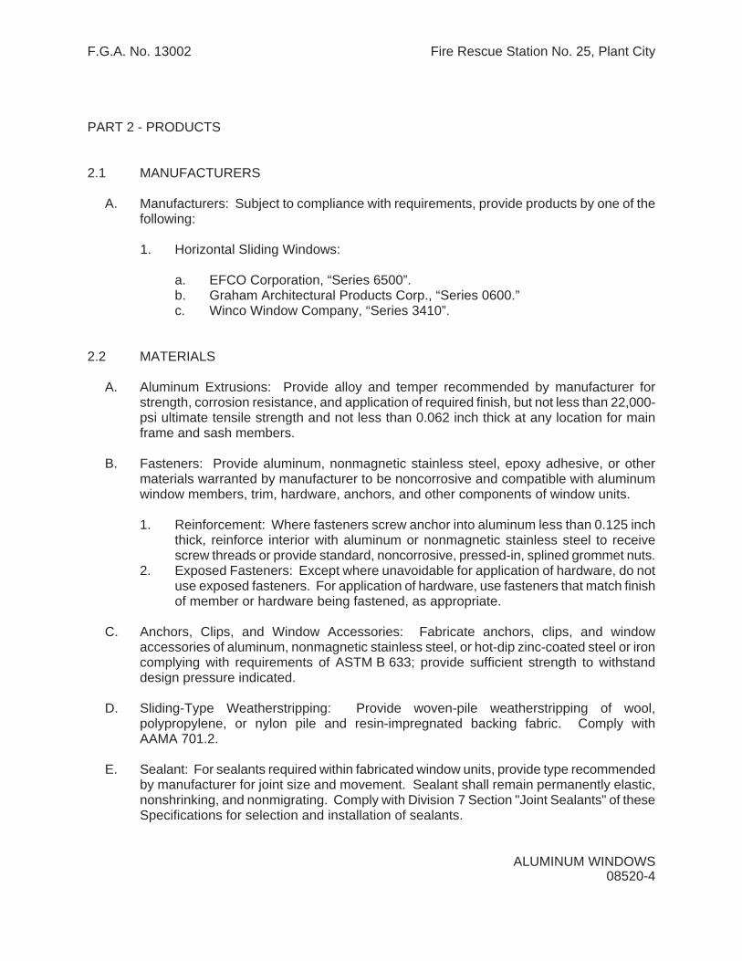
F.G.A. No. 13002 Fire Rescue Station No. 25, Plant City
ALUMINUM WINDOWS 08520-4
PART 2 - PRODUCTS
2.1 MANUFACTURERS
A. Manufacturers: Subject to compliance with requirements, provide products by one of the following:
1. Horizontal Sliding Windows:
a. EFCO Corporation, “Series 6500”. b. Graham Architectural Products Corp., “Series 0600.” c. Winco Window Company, “Series 3410”.
2.2 MATERIALS
A. Aluminum Extrusions: Provide alloy and temper recommended by manufacturer for strength, corrosion resistance, and application of required finish, but not less than 22,000-psi ultimate tensile strength and not less than 0.062 inch thick at any location for main frame and sash members.
B. Fasteners: Provide aluminum, nonmagnetic stainless steel, epoxy adhesive, or other materials warranted by manufacturer to be noncorrosive and compatible with aluminum window members, trim, hardware, anchors, and other components of window units.
1. Reinforcement: Where fasteners screw anchor into aluminum less than 0.125 inchthick, reinforce interior with aluminum or nonmagnetic stainless steel to receive screw threads or provide standard, noncorrosive, pressed-in, splined grommet nuts.
2. Exposed Fasteners: Except where unavoidable for application of hardware, do not use exposed fasteners. For application of hardware, use fasteners that match finish of member or hardware being fastened, as appropriate.
C. Anchors, Clips, and Window Accessories: Fabricate anchors, clips, and window accessories of aluminum, nonmagnetic stainless steel, or hot-dip zinc-coated steel or iron complying with requirements of ASTM B 633; provide sufficient strength to withstand design pressure indicated.
D. Sliding-Type Weatherstripping: Provide woven-pile weatherstripping of wool, polypropylene, or nylon pile and resin-impregnated backing fabric. Comply with AAMA 701.2.
E. Sealant: For sealants required within fabricated window units, provide type recommended by manufacturer for joint size and movement. Sealant shall remain permanently elastic, nonshrinking, and nonmigrating. Comply with Division 7 Section "Joint Sealants" of these Specifications for selection and installation of sealants.

F.G.A. No. 13002 Fire Rescue Station No. 25, Plant City
ALUMINUM WINDOWS 08520-5
F. Glass-Fiber-Mesh Insect Screen: 18-by-16 or 18-by-14 mesh of plastic-coated glass-fiber threads, woven and fused to form a fabric mesh resistant to corrosion, shrinkage, stretch, impact damage, and weather deterioration. Comply with requirements of ASTM D 3656.
2.3 HARDWARE
A. General: Provide manufacturer's standard hardware fabricated from aluminum, stainless steel, or other corrosion-resistant material compatible with aluminum and of sufficient strength to perform the function for which it is intended.
B. Counterbalancing Mechanism: Comply with AAMA 902.2.
1. Sash-Balance Type: Concealed spiral type of size and capacity to hold sash stationary at any open position.
2.4 ACCESSORIES
A. General: Provide manufacturer's standard accessories that comply with indicated standards.
B. Insect Screens: Provide insect screens for each operable exterior sash or ventilator. Locate screens on inside or outside of window sash or ventilator, depending on window type. Design windows and hardware to accommodate screens in a tight-fitting, removable arrangement, with a minimum of exposed fasteners and latches.
1. Screen Frames: Fabricate frames of tubular-shaped, extruded- or formed-aluminum members of 0.040-inch minimum wall thickness, with mitered or coped joints and concealed mechanical fasteners. Finish frames to match window units.
a. Provide removable PVC spline-anchor concealing edge of screen frame.
C. Head and Jamb Closures: Provide manufacturer’s standard extruded aluminum head and jamb closures compatible with frame profiles provided.
2.5 HORIZONTAL SLIDING WINDOWS
A. Minimum Window Class and Grade: Comply with requirements of AAMA Performance Class HC-Heavy Commercial. Provide AAMA Performance Grade as required by wind pressures indicated on drawings. Window units shall successfully pass operating force test performance requirements specified in AAMA 101. Thermally broken construction is not required.
B. Hardware: Provide the following equipment and operating hardware:
1. Sash Rollers: Steel, lubricated ball-bearing rollers with nylon tires. 2. Sash Lock: Cam-action sweep sash lock and keeper at meeting rails.

F.G.A. No. 13002 Fire Rescue Station No. 25, Plant City
ALUMINUM WINDOWS 08520-6
2.7 FABRICATION
A. General: Fabricate aluminum window units to comply with indicated standards. Include a complete system for assembly of components and anchorage of window units.
1. Provide units that are reglazable without dismantling sash or ventilator framing. 2. Prepare window sash or ventilators for glazing, except where preglazing at the
factory is indicated.
B. Frames: Provide 3-5/8" minimum frame depth, with frame and sash extrusions of .062" minimum thickness, and with sill members of .094" minimum thickness. All horizontal rails shall be tubular.
C. Mullions: Provide mullions and cover plates as shown, matching window units, complete with anchors for support to structure and installation of window units. Allow for erection tolerances and provide for movement of window units due to thermal expansion and building deflections, as indicated.
D. Glazing Stops: Provide screw-applied or snap-on glazing stops, coordinated with glass selection and glazing system indicated. Finish to match window units.
E. Preglazed Fabrication: Preglaze window units at the factory where possible and practical for applications indicated. Comply with glass and glazing requirements of Division 8 Section "Glazing" of these Specifications and AAMA 101.
2.8 FINISHES
A. Comply with NAAMM "Metal Finishes Manual" for recommendations relative to applying and designating finishes.
B. Finish designations prefixed by AA conform to the system established by the Aluminum Association for designating aluminum finishes.
C. High-Performance Organic Finish: AA-C12C42R1x (Chemical Finish: cleaned with inhibited chemicals; Chemical Finish: acid-chromate-fluoride-phosphate conversion coating; Organic Coating: as specified below). Prepare, pretreat, and apply coating to exposed metal surfaces to comply with coating and resin manufacturers’ written instructions.
1. Fluoropolymer Two-Coat System: Manufacturer’s standard two-coat, thermocured system consisting of specially formulated inhibitive primer and flouropolymer color topcoat containing not less than 70 percent polyvinylidene fluoride resin by weight; complying with AAMA 2605.
a. Color and Gloss: As selected by Architect from manufacturer’s full range.

F.G.A. No. 13002 Fire Rescue Station No. 25, Plant City
ALUMINUM WINDOWS 08520-7
PART 3 - EXECUTION
3.1 INSPECTION
A. Inspect openings before installation. Verify that rough or masonry opening is correct and sill plate is level.
1. Masonry surfaces shall be visibly dry and free of excess mortar, sand, and other construction debris.
3.2 INSTALLATION
A. Comply with manufacturer's specifications and recommendations for installing window units, hardware, operators, and other components of the Work.
B. Set window units plumb, level, and true to line, without warp or rack of frames or sash. Provide proper support and anchor securely in place.
1. Separate aluminum and other corrodible surfaces from sources of corrosion or electrolytic action at points of contact with other materials by complying with requirements specified under "Dissimilar Materials" Paragraph in appendix to AAMA 101.
2. Set windows on .062” thick formed aluminum sill flashing provided by manufacturer, in finish to match windows.
C. Set sill members and other members in a bed of sealant or with joint fillers or gaskets, as shown on Shop Drawings, to provide weathertight construction. Refer to Division 7 Section "Joint Sealants" for compounds, fillers, and gaskets to be installed concurrently with window units. Coordinate installation with wall flashings and other components of the Work.
3.3 ADJUSTING
A. Adjust operating sash and hardware to provide a tight fit at contact points and at weatherstripping for smooth operation and a weathertight closure.
3.4 CLEANING
A. Clean aluminum surfaces promptly after installing windows. Exercise care to avoid damage to protective coatings and finishes. Remove excess glazing and sealant compounds, dirt, and other substances. Lubricate hardware and other moving parts.
B. Clean glass of preglazed units promptly after installing windows. Comply with requirements of Division 8 Section "Glazing" for cleaning and maintenance.

F.G.A. No. 13002 Fire Rescue Station No. 25, Plant City
ALUMINUM WINDOWS 08520-8
3.5 PROTECTION
A. Provide final protection and maintain conditions, in a manner acceptable to aluminum window manufacturer, that ensure window units are without damage or deterioration at the time of Substantial Completion.
END OF SECTION 08520

F.G.A. No. 13002 Fire Rescue Station No. 25, Plant City
SECTION 08710 - DOOR HARDWARE
PART 1 - GENERAL
1.1 RELATED DOCUMENTS
A. Drawings and general provisions of the Contract, including General and Supplementary Conditions and Division 1 Specification Sections, apply to this Section.
1.2 SUMMARY
A. This section includes items known commercially as finish or door hardware that are required for swing, sliding, and folding doors, except special types of unique hardware specified in the same sections as the doors and door frames on which they are to be installed.
B. This Section includes the following:
1. Hinges. 2. Key control systems. 3. Lock cylinders and keys. 4. Lock and latch sets. 5. Bolts. 6. Exit devices. 7. Push/pull units. 8. Closers. 9. Overhead holders. 10. Miscellaneous door control devices. 11. Protection plates. 12. Weatherstripping for exterior doors. 13. Astragals or meeting seals on pairs of doors. 14. Thresholds.
C. Related Sections: The following Sections contain requirements that relate to this Section:
1. Division 6 Section “Laminated Plastic Casework”. 2. Division 8 Section “Standard Steel Doors and Frames”. 3. Division 8 Section “Flush Wood Doors”. 4. Division 8 Section “Aluminum Entrances and Storefronts”.
D. Windstorm product approval requirements:
1. Hardware, except keyed cylinders, listed for entrance doors in this section is to indicate quality level and function required at each opening. Specific items listed may be modified as required to maintain windstorm product approvals for exterior openings, but in no case shall materials of lesser quality or different function be acceptable.
DOOR HARDWARE 08710 - 1

F.G.A. No. 13002 Fire Rescue Station No. 25, Plant City
1.3 SUBMITTALS
A. General: Submit the following in accordance with Conditions of Contract and Division 1 Specification sections.
B. Product data including manufacturer’s technical product data for each item of door hardware, installation instructions, maintenance of operating parts and finish, and other information necessary to show compliance with requirements.
C. Final hardware schedule coordinated with doors, frames, and related work to ensure proper size, thickness, hand, function, and finish of door hardware.
1. Final Hardware Schedule Content: Based on hardware indicated, organize schedule into “hardware sets” indicating complete designations of every item required for each door or opening. Include the following information:
a. Type, style, function, size, and finish of each hardware item. b. Name and manufacturer of each item. c. Fastenings and other pertinent information. d. Location of each hardware set cross referenced to indications on Drawings,
both on floor plans and in door and frame schedule. e. Explanation of all abbreviations, symbols, and codes contained in schedule. f. Mounting locations for hardware. g. Door and frame sizes and materials. h. Keying information.
2. Submittal Sequence: Submit final schedule at earliest possible date, particularly where acceptance of hardware schedule must precede fabrication of other work that is critical in the Project construction schedule. Include with schedule the product data, samples, shop drawings of other work affected by door hardware, and other information essential to the coordinated review of schedule.
3. Keying Schedule: Submit separate detailed schedule indicating clearly how the Owner’s final instructions on keying of locks has been fulfilled.
D. Submit samples of each type of exposed hardware unit as required in finish indicated and tagged with full description for coordination with schedule. Submit samples prior to submission of final hardware schedule.
1. Samples will be returned to the supplier. Units that are acceptable and remain undamaged through submittal, review, and field comparison process may, after final check of operation, be incorporated in the Work, within limitations of keying coordination requirements.
E. Templates for doors, frames, and other work specified to be factory prepared for the installation of door hardware. Check shop drawings of other work to confirm that adequate provisions are made for locating and installing door hardware to comply with indicated requirements.
F. For each electrified opening, provide complete wiring diagrams prepared by an authorized factory employee. Provide complete operational descriptions of electronic components listed by opening in the hardware submittals. Operational descriptions to
DOOR HARDWARE 08710 - 2

F.G.A. No. 13002 Fire Rescue Station No. 25, Plant City
detail how each electrical component functions within the opening incorporating all conditions of ingress and egress. Provide elevation drawings of electronic hardware and systems identifying locations of the system components with respect to their placement in the door opening. Provide a copy with each hardware schedule submitted for approval. Wiring diagrams may be submitted after approval of hardware schedule.
1.4 QUALITY ASSURANCE
A. Single Source Responsibility: Obtain each type of hardware (latch and lock sets, hinges, closers, etc.) from a single manufacturer.
B. Supplier Qualifications: A recognized architectural door hardware supplier, with warehousing facilities in the Project’s vicinity, that has a record of successful in-service performance for supplying door hardware similar in quantity, type, and quality to that indicated for this Project and that employs an experienced architectural hardware consultant (AHC) who is available to Owner, Architect, and Contractor, at reasonable times during the course of the Work, for consultation.
1. Require supplier to meet with Owner to finalize keying requirements and to obtain final instructions in writing.
C. Fire-Rated Openings: Provide door hardware for fire-rated openings that complies with NFPA Standard No. 80 and requirements of authorities having jurisdiction. Provide only items of door hardware that are listed and are identical to products tested by UL, Warnock Hersey, FM, or other testing and inspecting organization acceptable to authorities having jurisdiction for use on types and sizes of doors indicated in compliance with requirements of fire-rated door and door frame labels. All fire seals required for fire rated wood doors shall be furnished by the door manufacturer or supplier.
D. Disabled Accessibility: Provide hardware that complies with all accessibility codes as they pertain to this project, including the Americans with Disabilities Act Accessibility Guidelines and the Florida Accessibility Code for Building Construction.
E. Exterior Openings: All doors, frames and hardware for exterior openings shall be tested and approved for use at the required wind loads for this project. Copies of current valid Florida State or Metro-Dade County product approvals shall be furnished as proof of compliance with this requirement.
1.5 PRODUCT HANDLING
A. Tag each item or package separately with identification related to final hardware schedule, and include basic installation instructions with each item or package.
B. Packaging of door hardware is responsibility of supplier. As material is received by hardware supplier from various manufacturers, sort and repackage in containers clearly marked with appropriate hardware set number to match set numbers of approved hardware schedule. Two or more identical sets may be packed in same container.
C. Inventory door hardware jointly with representatives of hardware supplier and hardware installer until each is satisfied that count is correct.
DOOR HARDWARE 08710 - 3

F.G.A. No. 13002 Fire Rescue Station No. 25, Plant City
D. Deliver individually packaged door hardware items promptly to place of installation (shop or Project site).
E. Provide secure lock-up for door hardware delivered to the Project, but not yet installed. Control handling and installation of hardware items that are not immediately replaceable so that completion of the Work will not be delayed by hardware losses both before and after installation.
1.6 MAINTENANCE
A. Maintenance Tools and Instructions: Furnish a complete set of specialized tools and maintenance instructions as needed for Owner’s continued adjustment, maintenance, and removal and replacement of door hardware.
PART 2 - PRODUCTS
2.1 MANUFACTURERS
A. Manufacturers: Subject to compliance with requirements, provide products by one of the following:
1. Butts and Hinges:
a. Hager Hinge Co. b. McKinney Products Co, an ASSA ABLOY Group Company. c. Stanley Hardware, Div. Stanley Works.
2. Pivots
a. Rixson, an ASSA ABLOY Group company.
3. Key Control System
a. Telkee Inc. b. Lund Equipment Company, Inc. c. MMF Industries
4. Cylinders and Locks:
a. Schlage IR Security and Safety. L9000 series, 03A trim. b. Corbin Russwin Architectural Hardware, an ASSA ABLOY Group Company ML2000 Series, LSA trim
5. Bolts
a. Corbin Russwin Architectural Hardware, an ASSA ABLOY Group Company. b. McKinney Products Co, an ASSA ABLOY Group Company. c. Rockwood Manufacturing. d. Triangle Brass Manufacturing Company (TRIMCO).
DOOR HARDWARE 08710 - 4

F.G.A. No. 13002 Fire Rescue Station No. 25, Plant City
6. Exit/Panic Devices
a. Von Duprin, IR Security and Safety. 98 series, 03 lever trim. b. Corbin Russwin Architectural Hardware, an ASSA ABLOY Group Company 5000 Series, Lustra lever trim
7. Push/Pull Units:
a. Rockwood Manufacturing, as ASSA ABLOY Group Company b. Triangle Brass Manufacturing Company (Trimco). c. Ives, IR security and Safety
8. Overhead Closers:
a. Corbin Russwin Architectural Hardware, an ASSA ABLOY Group Company. DC6000 series.
b. LCN, IR Security and Safety. 4041 series. c. Norton Door Controls, an ASSA ABLOY Group Company. 7500 series.
9. Door Control Devices:
a. Glynn-Johnson, IR Security and Safety. b. Ives, IR Security and Safety. c. McKinney Products Co, an ASSA ABLOY Group Company. d. Rixson Specialty Door Controls, an ASSA ABLOY Group Company. e. Rockwood Manufacturing ,an ASSA ABLOY Group Company f. Triangle Brass Manufacturing Company (Trimco).
10. Kick, Mop, and Armor Plates:
a. Ives, IR Security and Safety. b. Rockwood Manufacturing. c. Triangle Brass Manufacturing Company (Trimco).
11. Door Stripping and Seals:
a. National Guard Products, Inc. b. Pemko Manufacturing Co., Inc. c. Reese Enterprises, Inc. d. Zero International, Inc.
12. Thresholds:
a. National Guard Products, Inc. b. Pemko Manufacturing Co., Inc. c. Reese Enterprises Inc. d. Zero International, Inc.
DOOR HARDWARE 08710 - 5

F.G.A. No. 13002 Fire Rescue Station No. 25, Plant City
13. Astragals:
a. National Guard Products, Inc. b. Pemko Manufacturing Co. Inc. c. Reese Enterprises, Inc. d. McKinney Products Co, an ASSA ABLOY Group Company. e. Zero International, Inc.
2.2 SCHEDULED HARDWARE
A. Requirements for design, grade, function, finish, size, and other distinctive qualities of each type of finish hardware are indicated in the “Hardware Schedule” at the end of this Section. Products are identified by using hardware designation numbers of the following:
1. Manufacturer’s Product Designations: The product designation and name of one manufacturer are listed for each hardware type required for the purpose of establishing minimum requirements. Provide either the product designated or, where more than one manufacturer is specified under the Article “Manufacturers” in Part 2 for each hardware type, the comparable product of one of the other manufacturers that complies with requirements.
2. ANSI/BHMA designations used elsewhere in this Section or in schedules to describe hardware items or to define quality or function are derived from the following standards. Provide products complying with these standards and requirements specified elsewhere in this Section.
a. Butts and Hinges: ANSI/BHMA A156.1-06. b. Bored and Preassembled Locks and Latches: ANSI/BHMA A156.2-03. c. Exit Devices: ANSI/BHMA A156.3-01. d. Door Controls - Closers: ANSI/BHMA A156.4-00. e. Auxiliary Locks and Associated Products: ANSI/BHMA A156.5-01. f. Architectural Door Trim: ANSI/BHMA A156.6-05. g. Template Hinge Dimensions: ANSI/BHMA A156.7-03. h. Door Controls - Overhead Stops and Holders: ANSI/BHMA A156.8-05. i. Interconnected Locks and Latches: ANSI/BHMA A156.12-05. j. Mortise Locks and Latches Series 1000: ANSI/BHMA A156.13-05. k. Sliding and Folding Door Hardware: ANSI/BHMA A156.14-07. l. Release Devises – Closer Holder, Electromagnetic and Electromechanical:
ANSI/BHMA A156.15-06. m. Auxiliary Hardware: ANSI/BHMA A156.16-02. n. Self-Closing Hinges and Pivots: ANSI/BHMA A156.17-04. o. Recommended Practices for Materials and Finishes: ANSI/BHMA A156.18-
06.p. Power Assist and Low Energy Operated Doors: ANSI/BHMA A156.19-07. q. Strap and Tee Hinges and Hasps: ANSI/BHMA A156.20-06. r. Thresholds: ANSI/BHMA A156.21-06. s. Door Gasketing and Edge Seal Systems: ANSI/BHMA A156.22-05. t. Electromagnetic Locks: ANSI/BHMA A156.23-04.
DOOR HARDWARE 08710 - 6

F.G.A. No. 13002 Fire Rescue Station No. 25, Plant City
u. Delayed Egress Locking Systems: ANSI/BHMA A156.24-03. v. Electrified Locking Devices: ANSI/BHMA A156.25-02. w. Continuous Hinges: ANSI/BHMA A156.27-06. x. Recommended Practices for Keying Systems: ANSI/BHMA A156.28.07. y. Exit Locks, Exit Locks with Exit Alarms, Exit Alarms, Alarms for Exit Devices:
ANSI/BHMA A156.29-07. z. High Security Cylinders: ANSI/BHMA A156.30-03. aa. Electric Strikes and Frame Mounted actuators: ANSI/BHMA A156.31-07.
2.3 MATERIALS AND FABRICATION
A. Manufacturer’s Name Plate: Do not use manufacturers’ products that have manufacturer’s name or trade name displayed in a visible location (omit removable nameplates) except in conjunction with required fire-rated labels and as otherwise acceptable to Architect.
1. Manufacturer’s identification will be permitted on rim of lock cylinders only.
B. Base Metals: Produce hardware units of basic metal and forming method indicated using manufacturer’s standard metal alloy, composition, temper, and hardness, but in no case of lesser (commercially recognized) quality than specified for applicable hardware units for finish designations indicated.
C. Fasteners: Provide hardware manufactured to conform to published templates, generally prepared for machine screw installation. Do not provide hardware that has been prepared for self-tapping sheet metal screws, except as specifically indicated.
D. Furnish screws for installation with each hardware item. Provide Phillips flat-head screws except as otherwise indicated. Finish exposed (exposed under any condition) screws to match hardware finish or, if exposed in surfaces of other work, to match finish of this other work as closely as possible including “prepared for paint” surfaces to receive painted finish.
E. Provide concealed fasteners for hardware units that are exposed when door is closed except to the extent no standard units of type specified are available with concealed fasteners. Do not use thru-bolts for installation where bolt head or nut on opposite face is exposed in other work unless their use is the only means of reinforcing the work adequately to fasten the hardware securely. Where thru-bolts are used as a means of reinforcing the work, provide sleeves for each thru-bolt or use sex screw fasteners.
F. Electrified Hardware: For each item of electrified hardware specified, provide standardized Molex™ plug connectors to accommodate up to eight (8) wires or as required. Molex™ plug connectors shall plug directly into through-door wiring harnesses, frame wiring harnesses, electric locking devices and power supplies. Provide an Operation Narrative for each electrified hardware opening.
2.4 HINGES, BUTTS, AND PIVOTS
A. Templates: Except for hinges and pivots to be installed entirely (both leaves) into wood doors and frames, provide only template-produced units.
DOOR HARDWARE 08710 - 7

F.G.A. No. 13002 Fire Rescue Station No. 25, Plant City
B. Screws: Provide Phillips flat-head screws complying with the following requirements:
1. For metal doors and frames install machine screws into drilled and tapped holes. 2. For wood doors and frames install wood screws. 3. For fire-rated wood doors install#12 x 1-1/4-inch, threaded-to-the-head steel wood
screws.4. Finish screw heads to match surface of hinges or pivots.
C. Hinge Pins: Except as otherwise indicated, provide hinge pins as follows:
1. Out-Swing Exterior Doors: Non-removable pins. 2. Out-Swing Corridor Doors with Locks: Non-removable pins. 3. Interior Doors: Non-rising pins. 4. Tips: Flat button and matching plug, finished to match leaves, except where
hospital tip (HT) is indicated.
D. Number of Hinges: Provide number of hinges indicated but not less than 3 hinges per door leaf for doors 90 inches or less in height and one additional hinge for each 30 inches of additional height.
1. Fire-Rated Doors: Not less than 3 hinges per door leaf for doors 86 inches or less in height with same rule for additional hinges.
2.5 LOCK CYLINDERS AND KEYING
A. Standard System: Except as otherwise indicated, provide new masterkey system for Project.
B. Equip locks with manufacturer’s special 6-pin tumbler cylinder with construction masterkey feature that permits voiding of construction keys without cylinder removal.
C. Equip locks with cylinders for interchangeable-core pin tumbler inserts. Furnish only temporary inserts for the construction period, and remove these when directed. Furnish for all exit devices that would require dismantling of device in order to change keying of cylinder.
D. Metals: Construct lock cylinder parts from brass or bronze, stainless steel, or nickel silver.
E. Comply with Owner’s instructions for masterkeying and, except as otherwise indicated, provide individual change key for each lock that is not designated to be keyed alike with a group of related locks.
1. Permanently inscribe each key with number of lock that identifies cylinder manufacturer’s key symbol, and notation, “DO NOT DUPLICATE”.
F. Key Material: Provide keys of nickel silver only.
G. Key Quantity: Furnish 3 change keys for each lock, 6 master keys for each master system, and 6 grandmaster keys for each grandmaster system.
DOOR HARDWARE 08710 - 8

F.G.A. No. 13002 Fire Rescue Station No. 25, Plant City
1. Furnish one extra blank for each lock. 2. Furnish ten construction Keys. 3. Furnish three control keys for construction cores to remove / insert construction
cores.4. Furnish two control keys for permanent cores to remove / insert permanent cores. 5. Deliver all permanent keys to Owner.
2.6 KEY CONTROL SYSTEM
A. Provide a key control system including envelopes, labels, tags with self-locking key clips, receipt forms, 3-way visible card index, temporary markers, permanent markers, and standard metal cabinet, all as recommended by system manufacturer, with capacity for 150 percent of the number of locks required for the Project.
1. Provide hinged-panel type cabinet for wall mounting; install where directed by Owner.
2.7 LOCKS, LATCHES, AND BOLTS
A. Strikes: Provide manufacturer’s standard wrought box strike for each latch or lock bolt, with curved lip extended to protect frame, finished to match hardware set, unless otherwise indicated.
1. Provide curved lip strikes for locks with 3-piece, anti-friction latchbolts as recommended by manufacturer.
2. Provide extra long strike lips for locks used on frames with applied wood casing trim. Provide special strike lip for pairs of doors to allow astragal to be applied without modification or conflict with strike.
3. Provide recess type top strikes for bolts locking into frame heads, unless otherwise indicated.
4. Provide dust-proof strikes for foot bolts, except where special threshold construction provides non-recessed strike for bolt.
5. Provide roller type strikes where recommended by manufacturer of the latch and lock units.
6. Provide standard (open) strike plates for interior doors of residential units where wood door frames are used.
B. Lock Throw: Provide 3/4-inch minimum throw of latch on pairs of doors. Comply with UL requirements for throw of bolts and latch bolts on rated fire openings.
1. Provide 1/2-inch minimum throw of latch for other bored and pre-assembled types of locks and 3/4-inch minimum throw of latch for mortise locks. Provide 1-inch minimum throw for all dead bolts.
C. Flush Bolt Heads: Minimum of 1/2-inch-diameter rods of brass, bronze, or stainless steel with minimum 12-inch-long rod for doors up to 7'-0" in height. Provide longer rods as necessary for doors exceeding 7'-0" in height.
D. Exit Device Dogging: Except on fire-rated doors where closers are provided on doors equipped with exit devices, equip the units with keyed dogging device to keep the latch
DOOR HARDWARE 08710 - 9

F.G.A. No. 13002 Fire Rescue Station No. 25, Plant City
bolt retracted, when engaged.
E. Rabbeted Doors: Where rabbeted door stiles are indicated, provide special rabbeted front on lock and latch units and bolts.
2.8 PUSH/PULL UNITS
A. Concealed Fasteners: Provide manufacturer’s special concealed fastener system for installation, thru-bolted for matched pairs but not for single units.
2.9 CLOSERS AND DOOR CONTROL DEVICES
A. Size of Units: Except as otherwise specifically indicated, furnish units that are adjustable through a range of sizes (1 – 6).
1. Provide parallel arms for all overhead closers, except as otherwise indicated.
B. Provide heavy duty forged arms as listed. Where closers are indicated to be closer/stop, provide units with a rigid arm assembly and a heavy duty bracket with built-in lug to provide a means of positive stop. For closers where indicated to have spring stop, furnish a heavy duty bracket with spring to allow a cushion prior to door stopping. For closer/holders, provide units with an additional built-in holder designed to hold open against normal wind and traffic conditions. Holder shall be activated manually. For closers listed with Unitrol arms, provide the closer arms with a five degree cushion stop with stop locate on the arm, not the bracket. As an alternate to Unitrol arms, the supplier may furnish solid heavy duty forged arms with appropriate bracket and a heavy duty overhead stop and holder.
C. Access-Free Manual Closers: Where manual closers are indicated for doors required to be accessible to the physically handicapped, provide adjustable units complying with ANSI A117.1 provisions for door opening force and delayed action closing.
D. Provide black resilient parts for exposed bumpers.
2.10 DOOR TRIM UNITS
A. Fasteners: Provide manufacturer’s standard exposed fasteners for door trim units consisting of either machine screws or self-tapping screws.
B. Fabricate protection plates not more than 2 inches less than door width on hinge side and not more than 2 inch less than door width on pull side by height indicated.
1. Metal Plates: Stainless steel, 0.050 inch(U.S. 18 gage). 2. Metal Plates: Polished Aluminum with diamond pattern, 0.125 inch where
indicated.
2.11 WEATHERSTRIPPING AND SEALS
A. General: Provide continuous weatherstripping on exterior doors and smoke, light, or sound seals on interior doors where indicated or scheduled. Provide non-corrosive fasteners for exterior applications and elsewhere as indicated.
DOOR HARDWARE 08710 - 10

F.G.A. No. 13002 Fire Rescue Station No. 25, Plant City
B. Replaceable Seal Strips: Provide only those units where resilient or flexible seal strip is easily replaceable and readily available from stocks maintained by manufacturer.
2.12 THRESHOLDS
A. General: Except as otherwise indicated, provide standard metal threshold unit of type, size, and profile as shown or scheduled.
2.13 HARDWARE FINISHES
A. Match items to the manufacturer’s standard color and texture finish for the latch and lock sets (or push-pull units if no latch or lock sets).
B. Provide finishes that match those established by BHMA or, if none established, match the Architect’s sample.
C. Provide quality of finish, including thickness of plating or coating (if any), composition, hardness, and other qualities complying with manufacturer’s standards, but in no case less than specified by referenced standards for the applicable units of hardware.
D. Provide protective lacquer coating on all exposed hardware finishes of brass, bronze, and aluminum, except as otherwise indicated. The suffix A-NL@ is used with standard finish designations to indicate “no lacquer”.
E. The designations used in schedules and elsewhere to indicate hardware finishes are those listed in ANSI/BHMA A156.18, “Materials and Finishes”, including coordination with the traditional U.S. finishes shown by certain manufacturers for their products.
F. The designations used in schedules and elsewhere to indicate hardware finishes are the industry-recognized standard commercial finishes, except as otherwise noted.
1. Rust-Resistant Finish: For iron and steel base metal required for exterior work and in areas shown as “High Humidity” areas (and also when designed with the suffix-RR), provide 0.2-mil-thick copper coating on base metal before applying brass, bronze, nickel, or chromium plated finishes.
PART 3 - EXECUTION
3.1 INSTALLATION
A. Mount hardware units at heights indicated in following applicable publications, except as specifically indicated or required to comply with governing regulations and except as otherwise directed by Architect.
1. “Recommended Locations for Builders Hardware for Standard Steel Doors and Frames” by the Door and Hardware Institute.
2. WDMA Industry Standard I.S.1.7, “Hardware Locations for Wood Flush Doors”.
B. Install each hardware item in compliance with the manufacturer’s instructions and
DOOR HARDWARE 08710 - 11

F.G.A. No. 13002 Fire Rescue Station No. 25, Plant City
recommendations. Where cutting and fitting is required to install hardware onto or into surfaces that are later to be painted or finished in another way, coordinate removal, storage, and reinstallation or application of surface protection with finishing work specified in the Division 9 Sections. Do not install surface-mounted items until finishes have been completed on the substrates involved.
C. Set units level, plumb, and true to line and location. Adjust and reinforce the attachment substrate as necessary for proper installation and operation.
D. Drill and countersink units that are not factory prepared for anchorage fasteners. Space fasteners and anchors in accordance with industry standards.
E. Set thresholds for exterior doors in full bed of butyl-rubber or polyisobutylene mastic sealant complying with requirements specified in Division 7 Section “Joint Sealers”.
F. Weatherstripping and Seals: Comply with manufacturer’s instructions and recommendations to the extent installation requirements are not otherwise indicated.
3.2 ADJUSTING, CLEANING, AND DEMONSTRATING
A. Adjust and check each operating item of hardware and each door to ensure proper operation or function of every unit. Replace units that cannot be adjusted to operate freely and smoothly or as intended for the application made.
1. Where door hardware is installed more than one month prior to acceptance or occupancy of a space or area, return to the installation during the week prior to acceptance or occupancy and make final check and adjustment of all hardware items in such space or area. Clean operating items as necessary to restore proper function and finish of hardware and doors. Adjust door control devices to compensate for final operation of heating and ventilating equipment.
B. Clean adjacent surfaces soiled by hardware installation.
C. Instruct Owner’s personnel in the proper adjustment and maintenance of door hardware and hardware finishes.
D. Six-Month Adjustment: Approximately six months after the date of Substantial Completion, the Installer, accompanied by representatives of the manufacturers of latchsets and locksets and of door control devices, and of other major hardware suppliers, shall return to the Project to perform the following work:
1. Examine and re-adjust each item of door hardware as necessary to restore function of doors and hardware to comply with specified requirements.
2. Consult with and instruct Owner’s personnel in recommended additions to the maintenance procedures.
3. Replace hardware items that have deteriorated or failed due to faulty design, materials, or installation of hardware units.
4. Prepare a written report of current and predictable problems (of substantial nature) in the performance of the hardware.
DOOR HARDWARE 08710 - 12

F.G.A. No. 13002 Fire Rescue Station No. 25, Plant City
3.3 HARDWARE SCHEDULE
A. General: Provide hardware for each door to comply with requirements of Section “Door Hardware”, hardware set numbers indicated in door schedule, and in the following schedule of hardware sets.
1. Hardware sets indicate quantity, item, manufacturer and product designation, size, and finish or color, as applicable.
Hardware Sets
HARDWARE SETS
SET 1.1
Doors: X101 Each to have: 1 set Pivots 147 626 RX 1 Int. Pivot M19 626 RX 1 Rim Exit Device XP98L 996Lx17 630 VO 1 I C Cylinder As Required 626 SC 1 Surface Closer 4041PA-EDA AL LN 1 Weather Seal By Door MFG 1 Threshold By Door Mfg.
NOTE: Hardware listed is basis of design. All exterior openings to comply with FBC windload requirements as per Para.1.2.D.1
SET 1.2
Doors: X118 Each to have: 3 Hinges T4B2314-NRP 4 1/2 x 4 1/2 630 MC 1 Rim Exit Device XP98L 996Lx17 630 VO 1 I C Cylinder As Required 626 SC 1 Surface Closer 4041-EDA PA As Required AL LN 1 Kick Plate K1050 10 x 2" LDW 630 RO 1 Weather Seal 296CR LAR AL PE 1 Threshold 2005AV LAR AL PE 1 Door Sweep 321CN LAR AL PE 1 Rain Guard 347A LAR AL PE 1 Guard Seal 68AR LAR AL PE NOTE: Hardware listed is basis of design. All exterior openings to comply with FBC windload requirements as per Para.1.2.D.1
DOOR HARDWARE 08710 - 13

F.G.A. No. 13002 Fire Rescue Station No. 25, Plant City
SET 1.3
Doors: X103 – X111 Each to have: 3 Hinges T4B2314-NRP 4 1/2 x 4 1/2 630 MC 1 Ext Lockset L9453R 17A 630 SC 1 Surface Closer 4041-EDA PA As Required AL LN 1 Kick Plate K1050 10 x 2" LDW 630 RO 1 Weather Seal 296CR LAR AL PE 1 Threshold 2005AV LAR AL PE 1 Door Sweep 321CN LAR AL PE 1 Rain Guard 347A LAR AL PE 1 Guard Seal 68AR LAR AL PE NOTE: Hardware listed is basis of design. All exterior openings to comply with FBC windload requirements as per Para.1.2.D.1
SET 1.4
Doors: X112 Each to have:
3 Hinges T4B2314-NRP 4 1/2 x 4 1/2 630 MC 1 Ext Lockset L9480R 17A 630 SC 1 Surface Closer 4041-EDA PA As Required AL LN 1 Kick Plate K1050 10 x 2" LDW 630 RO 1 Weather Seal 296CR LAR AL PE 1 Threshold 2005AV LAR AL PE 1 Door Sweep 321CN LAR AL PE 1 Rain Guard 347A LAR AL PE 1 Guard Seal 68AR LAR AL PE NOTE: Hardware listed is basis of design. All exterior openings to comply with FBC windload requirements as per Para.1.2.D.1
SET 1.5
Doors: X113 Each to have: 6 Hinges TA2314-NRP 4 1/2 x 4 1/2 630 MC 2 Surface Bolts 580 12" 630 RO 1 Storeroom Lock L9480R 17A 630 SC 2 Overhead Holders OH900 Series 630 RO 1 Weather Seal 296CR LAR AL PE 1 Threshold 177AV LAR AL PE 1 Door Sweep 321CN LAR AL PE 1 Rain Guard 347A LAR AL PE 1 Guard Seal 68AR LAR AL PE NOTE: Hardware listed is basis of design. All exterior openings to comply with FBC windload requirements as per Para.1.2.D.1
DOOR HARDWARE 08710 - 14
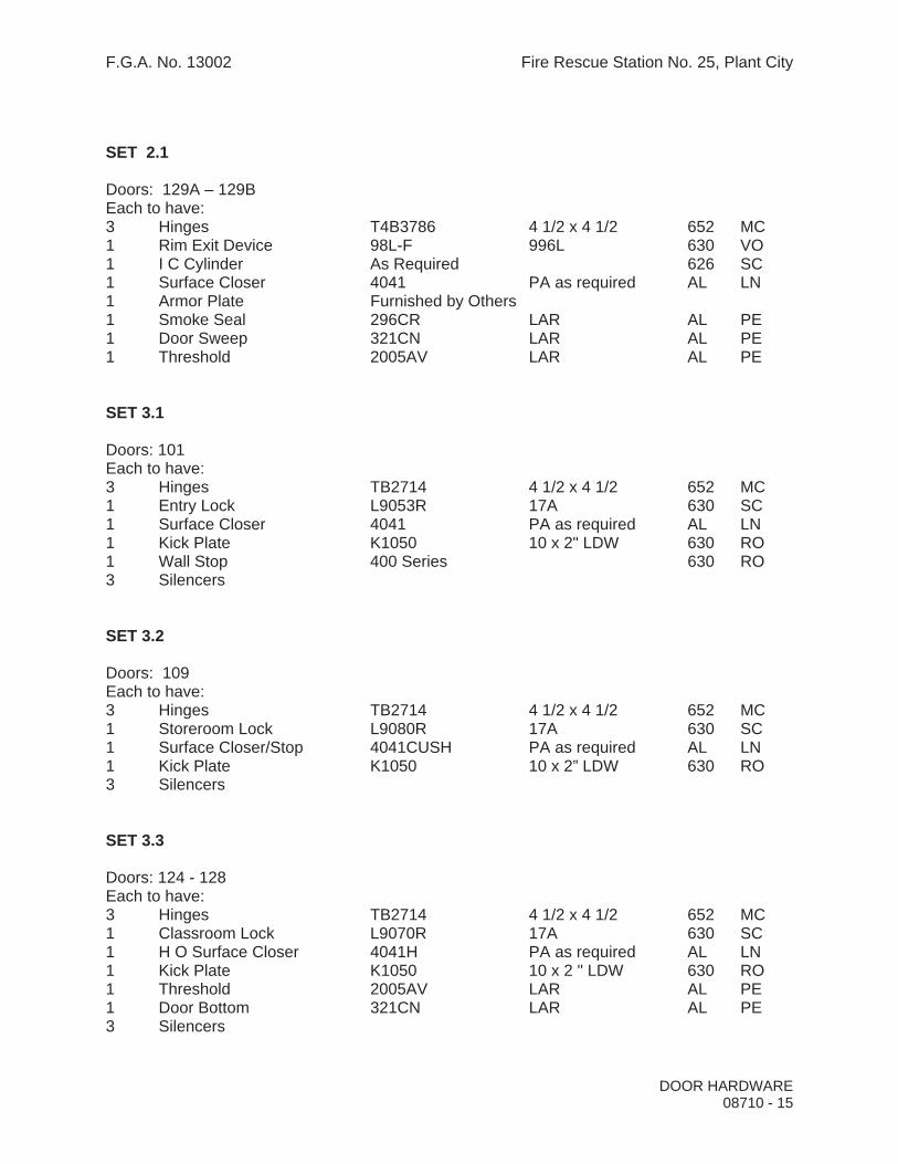
F.G.A. No. 13002 Fire Rescue Station No. 25, Plant City
SET 2.1
Doors: 129A – 129B Each to have: 3 Hinges T4B3786 4 1/2 x 4 1/2 652 MC 1 Rim Exit Device 98L-F 996L 630 VO 1 I C Cylinder As Required 626 SC 1 Surface Closer 4041 PA as required AL LN 1 Armor Plate Furnished by Others 1 Smoke Seal 296CR LAR AL PE 1 Door Sweep 321CN LAR AL PE 1 Threshold 2005AV LAR AL PE
SET 3.1
Doors: 101 Each to have: 3 Hinges TB2714 4 1/2 x 4 1/2 652 MC 1 Entry Lock L9053R 17A 630 SC 1 Surface Closer 4041 PA as required AL LN 1 Kick Plate K1050 10 x 2" LDW 630 RO 1 Wall Stop 400 Series 630 RO 3 Silencers
SET 3.2
Doors: 109 Each to have: 3 Hinges TB2714 4 1/2 x 4 1/2 652 MC 1 Storeroom Lock L9080R 17A 630 SC 1 Surface Closer/Stop 4041CUSH PA as required AL LN 1 Kick Plate K1050 10 x 2” LDW 630 RO 3 Silencers
SET 3.3
Doors: 124 - 128 Each to have: 3 Hinges TB2714 4 1/2 x 4 1/2 652 MC 1 Classroom Lock L9070R 17A 630 SC 1 H O Surface Closer 4041H PA as required AL LN 1 Kick Plate K1050 10 x 2 " LDW 630 RO 1 Threshold 2005AV LAR AL PE 1 Door Bottom 321CN LAR AL PE 3 Silencers
DOOR HARDWARE 08710 - 15

F.G.A. No. 13002 Fire Rescue Station No. 25, Plant City
SET 3.4
Doors: 117 – 118 - 127 Each to have: 3 Hinges TB2714 4 1/2 x 4 1/2 652 MC 1 Privacy Lock L9440 17A 630 SC 1 Surface Closer 4041 PA as required AL LN 1 Kick Plate K1050 10 x 2" LDW 620 RO 1 Wall Stop 400 Series 630 RO 3 Silencers
SET 3.5
Doors: 122Each to have: 3 Hinges TB2714 4 1/2 x 4 1/2 652 MC 1 Passage L9010 17A 630 SC 1 Surface Closer 4041 PA as required AL LN 1 Kick Plate K1050 10 x 2" LDW 630 RO 1 Wall Stop 400 Series 630 RO 3 Silencers
SET 3.6
Doors: 111 – 115 – 119 - 125 Each to have:
3 Hinges TB2714 4 1/2 x 4 1/2 652 MK 1 Push Plate 70 12 x 18 630 RO 1 Pull Plate 70C x 110 4 x 16 630 RO 1 Surface Closer 4041 PA as required AL LN 1 Kick Plate K1050 10 x 2" LDW 630 RO 1 Wall Stop 400 Series 630 RO 1 set Smoke Seal S88D PE 3 Silencers
SET 4.1
Doors: 103A - 113 Each to have:
3 Hinges T2714 4 1/2 x 4 1/2 652 MC 1 Office Lock L9050R 17A 630 SC 1 Wall Stop 400 Series 630 RO 3 Silencers
DOOR HARDWARE 08710 - 16

F.G.A. No. 13002 Fire Rescue Station No. 25, Plant City
SET 4.2
Doors: 106 – 107 - 108 Each to have:
3 Hinges TB2714 4 1/2 x 4 1/2 652 MC 1 Office Lock L9050R 17A 630 SC 1 Overhead Stop OH1000 Series 630 RO 3 Silencers
SET 4.3
Doors: 110 – 116 - 123 Each to have: 3 Hinges T2714 4 1/2 x 4 1/2 652 MC 1 Storeroom Lock L9080R 17A 630 SC 1 Wall Stop 400 Series 630 RO 3 Silencers
SET 4.4
Doors: 102 – 114 Each to have: 3 Hinges T2714 4 1/2 x 4 1/2 652 MC 1 Privacy Lock L9040 17A 630 SC 1 Wall Stop 400 Series 630 RO 3 Silencers
SET 4.5
Doors: 126A – 126B Each to have:
6 Hinges TA2714-NRP 4 1/2 x 4 1/2 652 MC 2 Surface Bolts 580 12" 630 RO 1 Storeroom Lock L9480R 17A 630 SC 2 Overhead Holders OH1000 Series 630 RO 1 Weather Seal 296CR LAR AL PE 1 Threshold 2001AT LAR AL PE 1 Door Sweep
SET 5.1
Doors: X115 – X116 – X117 – X120 – X121 – X122 Each to have:
Complete hardware by door mfg.
DOOR HARDWARE 08710 - 17

F.G.A. No. 13002 Fire Rescue Station No. 25, Plant City
DOOR HARDWARE 08710 - 18
Manufacturer List Code Name
AD Adams Rite MC McKinney LN LCN Closers PE Pemko SC Schlage RO Rockwood RX Rixson VO Von Duprin
END OF SECTION 08710

F.G.A. No. 13002 Fire Rescue Station No. 25, Plant City
SECTION 08800 - GLAZING
PART 1 - GENERAL
1.1 RELATED DOCUMENTS
A. Drawings and general provisions of the Contract, including General and Supplementary Conditions and Division 1 Specification Sections, apply to this Section.
1.2 SUMMARY
A. This Section includes glazing for the following products, including those specified in other Sections where glazing requirements are specified by reference to this Section:
1. Window units. 2. Vision lites. 3. Entrances and other doors. 4. Fixed glass, fire rated interior windows.
B. Related Sections: The following sections contain requirements that relate to this Section.
1. Glass for storefront entrances is specified in Division 8 Section “Aluminum Entrances and Storefronts”.
1.3 DEFINITIONS
A. Manufacturer is used in this Section to refer to a firm that produces primary glass or fabricated glass as defined in the referenced glazing standard.
1.4 SUBMITTALS
A. General: Submit the following according to Conditions of Contract and Division 1 Specification Sections.
B. Product data for each glass product and glazing material indicated.
C. Samples for verification purposes of 12-inch square samples of each type of glass indicated except for clear monolithic glass products, and 12-inch long samples of each color required (except black) for each type of sealant or gasket exposed to view. Install sealant or gasket sample between two strips of material representative in color of the adjoining framing system.
D. Product certificates signed by glazing materials manufacturers certifying that their products comply with specified requirements.
GLAZING08800-1

F.G.A. No. 13002 Fire Rescue Station No. 25, Plant City
1. Separate certifications are not required for glazing materials bearing manufacturer's permanent labels designating type and thickness of glass, provided labels represent a quality control program of a recognized certification agency or independent testing agency acceptable to authorities having jurisdiction.
1.5 QUALITY ASSURANCE
A. Glazing Publications: Comply with published recommendations of glass product manufacturers and organizations below, except where more stringent requirements are indicated. Refer to these publications for glazing terms not otherwise defined in this Section or in referenced standards.
1. FGMA Publications: "FGMA Glazing Manual."
B. Safety Glass: Products complying with ANSI Z97.1 and testing requirements of 16 CFR Part 1201 for Category II materials.
1. Subject to compliance with requirements, provide safety glass permanently marked with certification label of Safety Glazing Certification Council (SGCC) or other certification agency acceptable to authorities having jurisdiction.
C. Fire-Resistive Glazing Products for Door Assemblies: Products identical to those tested per ASTM E 152, labeled and listed by UL or another testing and inspecting agency acceptable to authorities having jurisdiction.
D. Fire-Resistive Glazing Products for Window Assemblies: Products identical to those tested per ASTM E 163, labeled and listed by UL or another testing and inspecting agency acceptable to authorities having jurisdiction.
E. Glazier Qualifications: Engage an experienced glazier who has completed glazing similar in material, design, and extent to that indicated for Project with a record of successful in-service performance.
F. Single-Source Responsibility for Glass: Obtain glass from one source for each product indicated below:
1. Primary glass of each (ASTM C 1036) type and class indicated. 2. Heat-treated glass of each (ASTM C 1048) condition indicated.
G. Single-Source Responsibility for Glazing Accessories: Obtain glazing accessories from one source for each product and installation method indicated.
1.6 DELIVERY, STORAGE, AND HANDLING
A. Protect glazing materials to comply with manufacturer's directions and as needed to prevent damage to glass and glazing materials from condensation, temperature changes, direct exposure to sun, or other causes.
GLAZING08800-2

F.G.A. No. 13002 Fire Rescue Station No. 25, Plant City
1.7 PROJECT CONDITIONS
A. Environmental Conditions: Do not proceed with glazing when ambient and substrate temperature conditions are outside the limits permitted by glazing materials manufacturer or when glazing channel substrates are wet from rain, frost, condensation, or other causes.
PART 2 - PRODUCTS
2.1 PRIMARY FLOAT GLASS PRODUCTS
A. Float Glass: ASTM C 1036, Type I (transparent glass, flat), and Quality q3 (glazing select).
2.2 HEAT-TREATED FLOAT GLASS
A. Uncoated, Clear, Heat-Treated Float Glass: ASTM C 1048, Condition A (uncoated surfaces), Type I (transparent glass, flat), Class 1 (clear), Quality q3 (glazing select), kind as indicated below, 1/4" thick:
1. Kind FT (fully tempered) in the following locations:
a. Interior door vision panels in doors in non fire-rated openings. b. Interior windows in non fire-rated openings.
2. Manufacturers: Subject to compliance with requirements, provide heat-treated glass by one of the following companies.
a. AFG Industries, Inc. b. Ford Glass Division c. Guardian Industries Corp. d. HGP & Affiliates, Inc. e. Pilkington LOF f. PPG Industries, Inc. g. Saint-Gobain h. Viracon, Inc.
B. High Performance, Uncoated, Green-Tinted, Heat-Treated Float Glass: ASTM C 1048, Condition A (uncoated surfaces), Type I (transparent glass, flat), Class 2 (tinted heat- absorbing and light-reducing), Quality q3 (glazing select); kind as indicated below, ¼”
thick:
1. Kind FT (Fully tempered) in the following locations:
a. Exterior Windows.
2. Manufacturer: Pilkington “Evergreen” (no substitutions).
GLAZING08800-3

F.G.A. No. 13002 Fire Rescue Station No. 25, Plant City
2.3 FIRE-PROTECTION-RATED CERAMIC GLAZING
A. Fire-Protection-Rated Glazing, General: Listed and labeled by a testing agency acceptable to authorities having jurisdiction, for fire-protection ratings indicated, based on testing according to NFPA 252 for door assemblies.
1. Install at all interior fire rated doors and windows.
B. Laminated Ceramic glazing: Laminated glass made from 2 plies of clear, ceramic flat glass; 5/16-inch (8-mm) total nominal thickness; complying with testing requirements in 16 CFR 1201 for Category II materials, and certified as approved safety glazing.
1. Subject to compliance with requirements, provide one of the following:
. Nippon Electric Glass Co., Ltd. (distributed by Technical Glass Products); FireLite Plus.
a. Schott North America, Inc.; Laminated Pyran Crystal. b. Vetrotech Saint-Gobain; SGG Keralite FR-L.
2.4 ELASTOMERIC GLAZING SEALANTS
A. General: Provide products of type indicated, complying with the following requirements:
1. Compatibility: Select glazing sealants and tapes of proven compatibility with other materials they will contact, including glass products, seals of insulating glass units, and glazing channel substrates, under conditions of installation and service, as demonstrated by testing and field experience.
2. Suitability: Comply with sealant and glass manufacturer's recommendations for selecting glazing sealants and tapes that are suitable for applications indicated and conditions existing at time of installation.
3. Colors: Provide color of exposed joint sealants to comply with the following:
a. Provide selections made by Architect from manufacturer's full range of standard colors for products of type indicated.
B. Elastomeric Glazing Sealant Standard: Provide manufacturer's standard chemically curing, elastomeric sealants that comply with ASTM C 920 requirements.
2.5 GLAZING TAPES
A. Back-Bedding Mastic Glazing Tape: Preformed, butyl-based elastomeric tape with a solids content of 100 percent, nonstaining and nonmigrating in contact with nonporous surfaces, with or without spacer rod as recommended by tape and glass manufacturers for application indicated, packaged on rolls with a release paper backing, and complying with AAMA 800.
GLAZING08800-4

F.G.A. No. 13002 Fire Rescue Station No. 25, Plant City
B. Expanded Cellular Glazing Tape: Closed-cell, polyvinyl chloride foam tape, factory coated with adhesive on both surfaces, packaged on rolls with release liner protecting adhesive, and complying with AAMA 800 for product 810.5.
2.6 GLAZING GASKETS
A. Lock-Strip Gaskets: Neoprene extrusions in size and shape indicated, fabricated into frames with molded corner units and zipper lock strips, complying with ASTM C 542, black.
B. Dense Compression Gaskets: Molded or extruded gaskets of material indicated below, complying with standards referenced with name of elastomer indicated below, and of profile and hardness required to maintain watertight seal:
1. Neoprene, ASTM C 864. 2. EPDM, ASTM C 864. 3. Silicone, ASTM C 1115. 4. Thermoplastic polyolefin rubber, ASTM C 1115. 5. Any material indicated above.
C. Soft Compression Gaskets: Extruded or molded closed-cell, integral-skinned gaskets of material indicated below, complying with ASTM C 509, Type II, black, and of profile and hardness required to maintain watertight seal:
1. Neoprene. 2. EPDM. 3. Silicone. 4. Thermoplastic polyolefin rubber. 5. Any material indicated above.
2.7 MISCELLANEOUS GLAZING MATERIALS
A. General: Provide products of material, size, and shape complying with referenced glazing standard, requirements of manufacturers of glass and other glazing materials involved for glazing application indicated, and with a proven record of compatibility with surfaces contacted in installation.
B. Cleaners, Primers and Sealers: Type recommended by sealant or gasket manufacturer.
C. Setting Blocks: Elastomeric material with a Shore A durometer hardness of 85 plus or minus 5.
D. Spacers: Elastomeric blocks or continuous extrusions with a Shore A durometer hardness required by glass manufacturer to maintain glass lites in place for installation indicated.
E. Edge Blocks: Elastomeric material of hardness needed to limit glass lateral movement (side-walking).
GLAZING08800-5

F.G.A. No. 13002 Fire Rescue Station No. 25, Plant City
2.8 FABRICATION OF GLASS AND OTHER GLAZING PRODUCTS
A. Fabricate glass and other glazing products in sizes required to glaze openings indicated for Project, with edge and face clearances, edge and surface conditions, and bite complying with recommendations of product manufacturer and referenced glazing standard as required to comply with system performance requirements.
PART 3 - EXECUTION
3.1 EXAMINATION
A. Examine glass framing, with glazier present, for compliance with the following:
1. Manufacturing and installation tolerances, including those for size, squareness, offsets at corners.
2. Presence and functioning of weep system where required. 3. Minimum required face or edge clearances. 4. Effective sealing between joints of glass-framing members.
B. Do not proceed with glazing until unsatisfactory conditions have been corrected.
3.2 PREPARATION
A. Clean glazing channels and other framing members receiving glass immediately before glazing. Remove coatings that are not firmly bonded to substrates.
3.3 GLAZING, GENERAL
A. Comply with combined recommendations of manufacturers of glass, sealants, gaskets, and other glazing materials, except where more stringent requirements are indicated, including those in referenced glazing publications.
B. Glazing channel dimensions as indicated on Drawings provide necessary bite on glass, minimum edge and face clearances, and adequate sealant thicknesses, with reasonable tolerances. Adjust as required by Project conditions during installation.
C. Protect glass from edge damage during handling and installation as follows:
1. Use a rolling block in rotating glass units to prevent damage to glass corners. Do not impact glass with metal framing. Use suction cups to shift glass units within openings; do not raise or drift glass with a pry bar. Rotate glass lites with flares or bevels on bottom horizontal edges so edges are located at top of opening, unless otherwise indicated by manufacturer's label.
GLAZING08800-6

F.G.A. No. 13002 Fire Rescue Station No. 25, Plant City
2. Remove damaged glass from Project site and legally dispose of off site. Damaged glass is glass with edge damage or other imperfections that, when installed, weaken glass and impair performance and appearance.
D. Apply primers to joint surfaces where required for adhesion of sealants, as determined by preconstruction sealant-substrate testing.
E. Install elastomeric setting blocks in sill rabbets, sized and located to comply with referenced glazing standard, unless otherwise required by glass manufacturer. Set blocks in thin course of compatible sealant suitable for heel bead.
F. Do not exceed edge pressures stipulated by glass manufacturers for installing glass lites.
G. Provide spacers for glass sizes larger than 50 united inches (length plus height) as follows:
1. Locate spacers inside, outside, and directly opposite each other. Install correct size and spacing to preserve required face clearances, except where gaskets and glazing tapes are used that have demonstrated ability to maintain required face clearances and comply with system performance requirements.
2. Provide 1/8-inch minimum bite of spacers on glass and use thickness equal to sealant width. With glazing tape, use thickness slightly less than final compressed thickness of tape.
H. Provide edge blocking to comply with requirements of referenced glazing publications, unless otherwise required by glass manufacturer.
I. Set glass lites in each series with uniform pattern, draw, bow, and similar characteristics.
J. Square cut wedge-shaped gaskets at corners and install gaskets in manner recommended by gasket manufacturer to prevent corners from pulling away; seal corner joints and butt joints with sealant recommended by gasket manufacturer.
3.4 TAPE GLAZING
A. Position tapes on fixed stops so that when compressed by glass their exposed edges are flush with or protrude slightly above sightline of stops.
B. Install tapes continuously but not in one continuous length. Do not stretch tapes to make them fit opening.
C. Where framing joints are vertical, cover these joints by applying tapes to heads and sills first and then to jambs. Where framing joints are horizontal, cover these joints by applying tapes to jambs and then to heads and sills.
D. Place joints in tapes at corners of opening with adjoining lengths butted together, not lapped. Seal joints in tapes with compatible sealant approved by tape manufacturer.
E. Do not remove release paper from tape until just before each lite is installed.
GLAZING08800-7

F.G.A. No. 13002 Fire Rescue Station No. 25, Plant City
F. Center glass lites in openings on setting blocks and press firmly against tape by inserting dense compression gaskets formed and installed to lock in place against faces of removable stops. Start gasket applications at corners and work toward centers of openings.
3.5 GASKET GLAZING (DRY)
A. Fabricate compression gaskets in lengths recommended by gasket manufacturer to fit openings exactly, with stretch allowance during installation.
B. Secure compression gaskets in place with joints located at corners to compress gaskets producing a weathertight seal without developing bending stresses in glass. Seal gasket joints with sealant recommended by gasket manufacturer.
C. Install gaskets so they protrude past face of glazing stops.
3.6 SEALANT GLAZING (WET)
A. Install continuous spacers between glass lites and glazing stops to maintain glass face clearances and to prevent sealant from extruding into glass channel weep systems until sealants cure. Secure spacers in place and in position to control depth of installed sealant relative to edge clearance for optimum sealant performance.
B. Force sealants into glazing channels to eliminate voids and to ensure complete wetting or bond of sealant to glass and channel surfaces.
C. Tool exposed surfaces of sealants to provide a substantial wash away from glass. Install pressurized gaskets to protrude slightly out of channel to eliminate dirt and moisture pockets.
3.7 PROTECTION AND CLEANING
A. Protect exterior glass from breakage immediately after installation by attaching crossed streamers to framing held away from glass. Do not apply markers to glass surface. Remove nonpermanent labels, and clean surfaces.
B. Protect glass from contact with contaminating substances resulting from construction operations including weld splatter. If, despite such protection, contaminating substances do come into contact with glass, remove them immediately as recommended by glass manufacturer.
C. Examine glass surfaces adjacent to or below exterior concrete and other masonry surfaces at frequent intervals during construction, but not less than once a month, for build-up of dirt, scum, alkali deposits, or stains, and remove as recommended by glass manufacturer.
D. Remove and replace glass that is broken, chipped, cracked, abraded, or damaged in any way, including natural causes, accidents and vandalism, during construction period.
GLAZING08800-8

F.G.A. No. 13002 Fire Rescue Station No. 25, Plant City
GLAZING08800-9
E. Wash glass on both faces in each area of Project not more than 4 days prior to date scheduled for inspections that establish date of Substantial Completion. Wash glass as recommended by glass manufacturer.
END OF SECTION 08800
F.G.A. No. 13002 Fire Rescue Station No. 25, Plant City
SECTION 09220 - PORTLAND CEMENT PLASTER
PART 1 - GENERAL
1.1 RELATED DOCUMENTS
A. Drawings and general provisions of the Contract, including General and Supplementary Conditions and Division 1 Specification Sections, apply to this Section.
1.2 SUMMARY
A. This Section includes the following:
1. Portland cement plaster. 1. Stucco finishes. 2. Plastic accessories.
1.3 SUBMITTALS
A. General: Submit each item in this Article according to the Conditions of the Contract and Division 1 Specification Sections.
B. Product Data for each product specified.
1.4 DELIVERY, STORAGE, AND HANDLING
A. Deliver cementitious materials to Project site in original packages, containers, or bundles, labeled with manufacturer's name, product brand name, and lot number.
B. Store materials inside, under cover, and dry, protected from weather, direct sunlight, surface contamination, aging, corrosion, and damage from construction traffic and other causes.
1.5 PROJECT CONDITIONS
A. Environmental Requirements, General: Comply with requirements of referenced plaster application standards and recommendations of plaster manufacturer for environmental conditions before, during, and after plaster application.
B. Warm-Weather Requirements: Protect plaster against uneven and excessive evaporation and from strong flows of dry air, both natural and artificial. Apply and cure plaster as required by climatic and job conditions to prevent dry out during cure period. Provide suitable coverings, moist curing, barriers to deflect sunlight and wind, or combinations of these, as required.
PORTLAND CEMENT PLASTER 09220 - 1

F.G.A. No. 13002 Fire Rescue Station No. 25, Plant City
C. Exterior Plaster Work: Do not apply plaster when ambient temperatures is below 40 deg F.
D. Protect contiguous work from soiling and moisture deterioration caused by plastering. Provide temporary covering and other provisions necessary to minimize harmful spattering of plaster on other work.
PART 2 - PRODUCTS
2.1 MANUFACTURERS
A. Manufacturers: Subject to compliance with requirements, provide products by one of the following:
1. Plastic Accessories:
a. Alabama Metal Industries Corp. (AMICO). b. Plastic Components, Inc. c. Vinyl Corp.
2. Stucco:
a. California Stucco Products Corp. b. Florida Stucco Corp. c. Highland Stucco. d. IPA Systems, Inc. e. United States Gypsum Co.
2.2 ACCESSORIES
A. General: Comply with material provisions of ASTM C 1063 and the requirements indicated below; coordinate depth of accessories with thickness and number of plaster coats required.
1. Plastic Components: ASTM D 4216, high-impact polyvinyl chloride (PVC) for building products.
B. Cornerbeads: Small nose cornerbeads fabricated from the following metal, with expanded flanges of large-mesh diamond-metal lath allowing full plaster encasement.
1. PVC Plastic: Minimum 0.035 inch thick.
C. Casing Beads: Square-edged style, with expanded flanges of the following material:
1. PVC Plastic: Minimum 0.035 inch thick.
PORTLAND CEMENT PLASTER 09220 - 2
F.G.A. No. 13002 Fire Rescue Station No. 25, Plant City
D. Control Joints: Prefabricated, of material and type indicated below:
1. PVC Plastic: Minimum 0.035 inch thick. 2. One-Piece Type: Folded pair of nonperforated screeds in M-shaped configuration,
with expanded or perforated flanges.
E. Reveals, Drip Screeds, Control Screeds, and Channel Screeds: Shapes as indicated on drawings, of material indicated below.
1. PVC Plastic: Minimum 0.035 inch thick.
2.5 PLASTER MATERIALS
A. Base-Coat Cements: Type as indicated below:
1. Portland cement, ASTM C 150, Type I.
B. Stucco Finish Coat: Manufacturer's standard factory-packaged stucco, including portland cement, aggregate, and other proprietary ingredients.
C. Sand Aggregate for Base Coats: ASTM C 897.
2.6 MISCELLANEOUS MATERIALS
A. Fiber for Base Coat: Alkaline-resistant glass or polypropylene fibers, ½ inch long, free of contaminates, manufactured for use in portland cement plaster.
B. Water for Mixing and Finishing Plaster: Potable.
C. Bonding Agent: ASTM C 932.
D. Acid-Etching Solution: Muriatic acid (10 percent solution of commercial hydrochloric acid) mixed 1 part to not less than 6 nor more than 10 parts water.
2.7 PLASTER MIXES AND COMPOSITIONS
A. General: Comply with ASTM C 926 for base- and finish-coat mixes as applicable to plaster bases, materials, and other requirements indicated.
B. Base-Coat Mixes and Compositions: Proportion materials for respective base coats in parts by volume per sum of cementitious materials for aggregates to comply with the following requirements for each method of application and plaster base indicated. Adjust mix proportions below within limits specified to attain workability.
C. Fiber Content: Add fiber to following mixes after ingredients have mixed at least 2 minutes. Comply with fiber manufacturer's written instructions but do not exceed 1 lb/cu. ft.of cementitious materials. Reduce aggregate quantities accordingly to maintain
PORTLAND CEMENT PLASTER 09220 - 3

F.G.A. No. 13002 Fire Rescue Station No. 25, Plant City
workability.
D. Two-Coat Work Over concrete unit masonry: 1/2” total thickness; base-coat proportions as indicated below:
1. Base Coat: 1 part Portland cement, 3/4 to 1-1/2 parts lime, 3 to 4 parts aggregate; 3/8" thickness.
E. Job-Mixed Finish Coats: Proportion materials for finish coats in parts by volume for cementitious materials and parts by volume per sum of cementitious materials to comply with the following requirements:
1. Proportions using sand aggregates as indicated below:
a. 1 part Portland cement, 3/4 to 1-1/2 parts lime, 3 parts sand; 1/8" thickness.
F. Stucco Finish Coat: (May be used in lieu of above described job mixed finish coat). Add water only; comply with stucco manufacturer’s written instructions; 1/8" thickness.
2.8 MIXING
A. Mechanically mix cementitious and aggregate materials for plasters to comply with applicable referenced application standard and with recommendations of plaster manufacturer.
PART 3 - EXECUTION
3.1 PREPARATIONS FOR PLASTERING
A. Clean plaster bases and substrates for direct application of plaster, removing loose material and substances that may impair the Work.
B. Etch concrete surfaces indicated for direct plaster application. Scrub with acid-etching solution on previously wetted surface and rinse thoroughly with clean water. Repeat application, if necessary, to obtain adequate suction and mechanical bond of plaster.
C. Apply bonding agent on concrete and concrete unit masonry surfaces indicated for direct plaster application; comply with manufacturer’s written instructions for application.
D. Install temporary grounds and screeds to ensure accurate rodding of plaster to true surfaces; coordinate with scratch-coat work.
PORTLAND CEMENT PLASTER 09220 - 4

F.G.A. No. 13002 Fire Rescue Station No. 25, Plant City
3.2 INSTALLATION OF PLASTERING ACCESSORIES
A. General: Comply with referenced lathing and furring installation standards for provision and location of plaster accessories of type indicated. Miter or cope accessories at corners; install with tight joints and in alignment. Attach accessories securely to plaster bases to hold accessories in place and in alignment during plastering. Install accessories of type indicated at following locations:
1. External Corners: Install corner reinforcement at external corners. 2. Terminations of Plaster: Install casing beads, unless otherwise indicated. 3. Control Joints: Install at locations indicated or, if not indicated, at locations
complying with the following criteria and approved by Architect:
a. Where an expansion or contraction joint occurs in surface of construction directly behind plaster membrane.
b. Distance between Control Joints: Not to exceed 18 feet in either direction or a length-to-width ratio of 2-1/2 to 1.
c. Wall Areas: Not more than 144 sq. ft.d. Horizontal Surfaces: Not more than 100 sq. ft. in area. e. Where plaster panel sizes or dimensions change, extend joints full width or
height of plaster membrane.
3.3 PLASTER APPLICATION
A. Plaster Application Standard: Apply plaster materials, composition, and mixes to comply with ASTM C 926.
B. Do not use materials that are caked, lumpy, dirty, or contaminated by foreign materials.
C. Do not use excessive water in mixing and applying plaster materials.
D. Flat Surface Tolerances: Do not deviate more than plus or minus 1/8 inch in 10 feet from a true plane in finished plaster surfaces, as measured by a 10-foot straightedge placed at any location on surface.
E. Sequence plaster application with installation and protection of other work so that neither will be damaged by installation of other.
F. Plaster flush with metal frames and other built-in metal items or accessories that act as a plaster ground, unless otherwise indicated. Where interior plaster is not terminated at metal frame by casing beads, cut base coat free from metal frame before plaster sets and groove finish coat at junctures with metal.
G. Corners: Make internal corners and angles square; finish external corners flush with cornerbeads on interior work, square and true with plaster faces on exterior work.
PORTLAND CEMENT PLASTER 09220 - 5

F.G.A. No. 13002 Fire Rescue Station No. 25, Plant City
PORTLAND CEMENT PLASTER 09220 - 6
H. Finish Coats: Apply finish coats to comply with the following requirements:
1. Float Finish: Apply finish coat to a minimum thickness of 1/8 inch to completely cover base coat, uniformly floated to a true even plane with “sand float” finish.
2. Prepared Finish: Apply factory-prepared finish coats according to manufacturer's written instructions.
I. Moist-cure plaster base and finish coats to comply with ASTM C 926, including written instructions for time between coats and curing in "Annex A2 Design Considerations."
3.4 CUTTING AND PATCHING
A. Cut, patch, replace, repair, and point up plaster as necessary to accommodate other work. Repair cracks and indented surfaces. Point-up finish plaster surfaces around items that are built into or penetrate plaster surfaces. Repair or replace work to eliminate blisters, buckles, check cracking, dry outs, efflorescence, excessive pinholes, and similar defects. Repair or replace work as necessary to comply with required visual effects.
3.5 CLEANING AND PROTECTING
A. Remove temporary covering and other provisions made to minimize spattering of plaster on other work. Promptly remove plaster from door frames, windows, and other surfaces not to be plastered. Repair surfaces stained, marred or otherwise damaged during plastering work. When plastering work is completed, remove unused materials, containers, equipment, and plaster debris.
B. Provide final protection and maintain conditions, in a manner acceptable to manufacturer and Installer, that ensure plaster work is without damage or deterioration at the time of Substantial Completion.
END OF SECTION 09220

F.G.A. No. 13002 Fire Rescue Station No. 25, Plant City
SECTION 09260 - GYPSUM BOARD ASSEMBLIES
PART 1 - GENERAL
1.1 RELATED DOCUMENTS
A. Drawings and general provisions of the Contract, including General and Supplementary Conditions and Division 1 Specification Sections, apply to this Section.
1.2 SUMMARY
A. This Section includes the following:
1. Nonload-bearing steel framing members for gypsum board assemblies. 2. Gypsum board assemblies attached to steel framing.
B. Related Sections: The following Sections contain requirements that relate to this Section:
1. Division 7 Section “Firestop Systems” for firestopping systems and fire-resistance-rated joint sealants.
2. Division 7 Section “Building Insulation” for sound attenuation insulation.
1.3 DEFINITIONS
A. Gypsum Board Construction Terminology: Refer to ASTM C 11 and GA-505 for definitions of terms for gypsum board assemblies not defined in this Section or in other referenced standards.
1.4 ASSEMBLY PERFORMANCE REQUIREMENTS
A. Sound Transmission Characteristics: For gypsum board assemblies with STC ratings, provide materials and construction identical to those of assemblies whose STC ratings were determined according to ASTM E 90 and classified according to ASTM E 413 by a qualified independent testing agency.
B. Fire Resistance: Provide gypsum board assemblies with fire-resistance ratings indicated.
1.5 SUBMITTALS
A. General: Submit each item in this Article according to the Conditions of the Contract and Division 1 Specification Sections.
B. Product Data for each type of product specified.
GYPSUM BOARD ASSEMBLIES 09260 - 1

F.G.A. No. 13002 Fire Rescue Station No. 25, Plant City
1.6 QUALITY ASSURANCE
A. Single-Source Responsibility for Steel Framing: Obtain steel framing members for gypsum board assemblies from a single manufacturer, unless otherwise indicated.
B. Single-Source Responsibility for Panel Products: Obtain each type of gypsum board and other panel products from a single manufacturer.
C. Single-Source Responsibility for Finishing Materials: Obtain finishing materials from either the same manufacturer that supplies gypsum board and other panel products or from a manufacturer acceptable to gypsum board manufacturer.
D. Fire-Test-Response Characteristics: Where fire-resistance-rated gypsum board assemblies are indicated, provide gypsum board assemblies that comply with the following requirements:
1. Fire-Resistance Ratings: As indicated by GA File Numbers in GA-600 “Fire Resistance Design Manual” or design designations in UL “Fire resistance Directory” or in the listing of another testing and inspecting agency acceptable to authorities having jurisdiction.
2. Gypsum board assemblies indicated are identical to assemblies tested for fire resistance according to ASTM E 119 by an independent testing and inspecting agency acceptable to authorities having jurisdiction.
1.7 DELIVERY, STORAGE, AND HANDLING
A. Deliver materials in original packages, containers, or bundles bearing brand name and identification of manufacturer or supplier.
B. Store materials inside under cover and keep them dry and protected against damage from weather, direct sunlight, surface contamination, corrosion, construction traffic, and other causes. Neatly stack gypsum panels flat to prevent sagging.
1.8 PROJECT CONDITIONS
A. Environmental Conditions, General: Establish and maintain environmental conditions for applying and finishing gypsum board to comply with ASTM C 840 requirements or gypsum board manufacturer's recommendations, whichever are more stringent.
B. Room Temperatures: For nonadhesive attachment of gypsum board to framing, maintain not less than 40 deg F. For adhesive attachment and finishing of gypsum board, maintain not less than 50 deg F for 48 hours before application and continuously after until dry. Do not exceed 95 deg F when using temporary heat sources.
C. Ventilation: Ventilate building spaces as required to dry joint treatment materials. Avoid drafts during hot, dry weather to prevent finishing materials from drying too rapidly.
GYPSUM BOARD ASSEMBLIES 09260 - 2
F.G.A. No. 13002 Fire Rescue Station No. 25, Plant City
PART 2 – PRODUCTS
2.1 MANUFACTURERS
A. Manufacturers: Subject to compliance with requirements, provide products by one of the following:
1. Steel Framing and Furring:
a. Clark Steel Framing, Inc. b. Consolidated Systems, Inc. c. Dale Industries, Inc. d. Dietrich Industries, Inc. e. Marino/Ware (formerly Marino Industries Corp.). f. National Gypsum Co.; Gold Bond Building Products Division. g. Unimast, Inc.
2. Grid Suspension Assemblies:
a. Armstrong World Industries, Inc. b. Chicago Metallic Corp. c. USG Interiors, Inc.
3. Gypsum Board and Related Products:
a. American Gypsum Co. b. Georgia-Pacific Corp. c. National Gypsum Co.; Gold Bond Building Products Division. d. United States Gypsum Co.
2.2 STEEL FRAMING COMPONENTS FOR SUSPENDED AND FURRED CEILINGS
A. General: Provide components complying with ASTM C 754 for conditions indicated.
B. Grid Suspension System for Interior Ceilings: ASTM C 645, manufacturer’s standard direct-hung grid suspension system composed of main beams and cross-furring members that interlock to form a modular supporting network.
2.3 STEEL FRAMING FOR WALLS AND PARTITIONS
A. General: Provide steel framing members complying with the following requirements:
1. Protective Coating: ASTM A 653, G 40 hot-dip galvanized coating.
B. Steel Studs and Runners: ASTM C 645, with flange edges of studs bent back 90 degrees and doubled over to form 3/16-inch- wide minimum lip (return), and complying with the following requirements for minimum thickness of base (uncoated) metal and for depth:
GYPSUM BOARD ASSEMBLIES 09260 - 3

F.G.A. No. 13002 Fire Rescue Station No. 25, Plant City
1. Thickness: 0.0179 inch (25 gage) unless otherwise indicated. 2. Thickness: 0.0329 inch, (20 gauge) as follows:
a. For head runner, sill runner, jamb, and cripple studs at door and other openings.
b. At partitions all around shower stalls.
3. Depth: 3 5/8” unless otherwise indicated on drawings.
C. Fasteners for Metal Framing: Provide fasteners of type, material, size, corrosion resistance, holding power, and other properties required to fasten steel framing and furring members securely to substrates involved; complying with the recommendations of gypsum board manufacturers for applications indicated.
2.4 GYPSUM BOARD PRODUCTS
A. General: Provide gypsum board of types indicated in maximum lengths available that will minimize end-to-end butt joints in each area indicated to receive gypsum board application.
1. Widths: Provide gypsum board in widths of 48 inches.
B. Gypsum Wallboard: ASTM C 36 and as follows:
1. Type: Regular for vertical surfaces, unless otherwise indicated. 2. Type: Type X where required for fire-resistance-rated assemblies. 3. Type: Moisture resistant for plumbing chase walls except showers. 4. Edges: Tapered. 5. Thickness: 5/8 inch unless otherwise indicated on drawings. 6. Type: Sag-resistant for ceiling surfaces (“ceiling board”) ½ “ thick.
C. Glass-Mat, Water-Resistant Gypsum Backing Board: ASTM C 1178, of type and thickness indicated below for installation at shower stalls:
1. Type and Thickness: Regular, 5/8 inch thick, unless otherwise indicated. 2. Products: Subject to compliance with requirements, provide “Dens-Shield Tile Backer” manufactured by G-P Gypsum Corp.
D. Paperless Drywall Panels: ASTM C 36 and ASTM C 1177/C, for installation in Toilet Rooms only, except behind tile at shower stalls:
1. Type and thickness: Regular, 5/8” thick with moisture and mold resistant core and surfaces.
2. Facing: Coated, glass mat. 3. Product: Subject to compliance with requirements, provide “DensArmor Plus
Paperless Interior Panel” panels manufactured by G-P Gypsum Corp.
GYPSUM BOARD ASSEMBLIES 09260 - 4

F.G.A. No. 13002 Fire Rescue Station No. 25, Plant City
2.5 TRIM ACCESSORIES
A. Accessories for Interior Installation: Cornerbead, edge trim, and control joints complying with ASTM C 1047 and requirements indicated below:
1. Material: Formed metal complying with the following requirement:
a. Steel sheet zinc coated by hot-dip process or rolled zinc.
2. Shapes indicated below by reference to Fig. 1 designations in ASTM C 1047:
a. Cornerbead on outside corners, unless otherwise indicated. b. J-bead with both face and back flanges; face flange formed to receive joint
compound. Use J-beads for edge trim, unless otherwise indicated. c. One-piece control joint formed with V-shaped slot and removable strip
covering slot opening.
B. Accessory for Curved Edges: Cornerbead formed of metal with either notched or flexible flanges that are bendable to curvature radius.
2.6 JOINT TREATMENT MATERIALS
A. General: Provide joint treatment materials complying with ASTM C 475 and the recommendations of both the manufacturers of sheet products and of joint treatment materials for each application indicated.
B. Joint Tape for Gypsum Board: Paper reinforcing tape, unless otherwise indicated.
C. Joint Tape for Glass Mat, Water-Resistant Gypsum Backer Units and Paperless Drywall: 2" 10 x 10 glass mesh tape embedded in setting compound recommended by panel manufacturer.
D. Drying-Type Joint Compounds for Gypsum Board: Factory-packaged vinyl-based products complying with the following requirements for formulation and intended use.
1. Ready-Mixed Formulation: Factory-mixed product.
a. All-purpose compound formulated for both taping and topping compounds.
2.7 ACOUSTICAL SEALANT
A. Acoustical Sealant for Exposed and Concealed Joints: Manufacturer’s standard nonsag, paintable, nonstaining latex sealant complying with ASTM C 834 and the following requirements:
1. Product is effective in reducing airborne sound transmission through perimeter joints and openings in building construction as demonstrated by testing representative assemblies according to ASTM E 90.
GYPSUM BOARD ASSEMBLIES 09260 - 5

F.G.A. No. 13002 Fire Rescue Station No. 25, Plant City
B. Acoustical Sealant for Exposed and Concealed Joints:
a. PL Acoustical Sealant; ChemRex, Inc.; Contech Brands. b. AC-20 FTR Acoustical and Insulation Sealant; Pecora Corp. c. SHEETROCK Acoustical Sealant; United States Gypsum Co.
2.8 MISCELLANEOUS MATERIALS
A. General: Provide auxiliary materials for gypsum board construction that comply with referenced standards and recommendations of gypsum board manufacturer.
B. Spot Grout: ASTM C 475, setting-type joint compound recommended for spot-grouting hollow metal door frames.
C. Steel drill screws complying with ASTM C 954 for fastening gypsum board to steel members from 0.033 to 0.112 inch thick.
D. Ready-Mixed Texture Compound: Type required for spray application of orange peel texture to all gypsum board walls.
PART 3 - EXECUTION
3.1 EXAMINATION
A. Examine substrates to which gypsum board assemblies attach or abut, installed hollow metal frames, cast-in-anchors, and structural framing, with installer present, for compliance with requirements for installation tolerances and other conditions affecting performance of assemblies specified in this Section. Do not proceed with installation until unsatisfactory conditions have been corrected.
3.2 PREPARATION
A. Ceiling Anchorages: Coordinate installation of ceiling suspension systems with installation of overhead structural assemblies to ensure that inserts and other provisions for anchorages to building structure have been installed to receive ceiling hangers that will develop their full strength and at spacing required to support ceilings.
3.3 INSTALLING STEEL FRAMING, GENERAL
A. Steel Framing Installation Standard: Install steel framing to comply with ASTM C 754 and with ASTM C 840 requirements that apply to framing installation.
GYPSUM BOARD ASSEMBLIES 09260 - 6

F.G.A. No. 13002 Fire Rescue Station No. 25, Plant City
B. Install supplementary framing, blocking, and bracing at terminations in gypsum board assemblies to support fixtures, equipment services, heavy trim, grab bars, toilet accessories, door bumpers, furnishings, or similar construction. Comply with details indicated and with recommendations of gypsum board manufacturer or, if none available, with United States Gypsum Co.'s "Gypsum Construction Handbook."
3.4 INSTALLING STEEL FRAMING FOR SUSPENDED AND FURRED CEILINGS
A. Suspend ceiling hangers from building structural members and as follows:
1. Install hangers plumb and free from contact with insulation or other objects within ceiling plenum that are not part of supporting structural or ceiling suspension system. Splay hangers only where required to miss obstructions and offset resulting horizontal forces by bracing, countersplaying, or other equally effective means.
2. Where width of ducts and other construction within ceiling plenum produces hanger spacings that interfere with the location of hangers required to support standard suspension system members, install supplemental suspension members and hangers in form of trapezes or equivalent devices. Size supplemental suspension members and hangers to support ceiling loads within performance limits established by referenced standards.
3. Secure wire hangers by looping and wire-typing, either directly to structures or to inserts, eyescrews, or other devices and fasteners that are secure and appropriate for structure as well as for type of hanger involved, and in a manner that will not cause them to deteriorate or otherwise fail.
4. Secure flat, angle, and rod hangers to structure, including intermediate framing members, by attaching to inserts, eyescrews, or other devices and fasteners that are secure and appropriate for structure as well as for type of hanger involved, and in a manner that will not cause them to deteriorate or otherwise fail.
5. Do not support ceilings directly from permanent metal forms. Furnish cast-in-place hanger inserts that extend through forms.
6. Do not attach hangers to steel deck tabs. 7. Do not attach hangers to steel roof deck. Attach hangers to structural members. 8. Do not connect or suspend steel framing from ducts, pipes, or conduit.
B. Install suspended steel framing components in sizes and at spacings indicated, but not less than that required by the referenced steel framing installation standard.
1. Wire Hangers: 48 inches o.c. 2. Main Tees: 48 inches o.c. 3. Cross Channels 24 inches o.c. 4. Cross Tees: As required for installation of recessed fluorescent light fixtures.
C. Installation Tolerances: Install steel framing components for suspended ceilings so that grid suspension members are level to within 1/8 inch in 12 feet as measured both lengthwise on each member and transversely between parallel members.
D. Grid Suspension System: Attach perimeter wall track or angle where grid suspension system meets vertical surfaces. Mechanically join main beam and cross-furring members to each other and butt-cut to fit into wall track.
GYPSUM BOARD ASSEMBLIES 09260 - 7

F.G.A. No. 13002 Fire Rescue Station No. 25, Plant City
3.5 INSTALLING STEEL FRAMING FOR WALLS AND PARTITIONS
A. Install runners (tracks) at floors, ceilings, and structural walls and columns where gypsum board stud assemblies abut other construction.
1. Where studs are installed directly against exterior walls, install asphalt felt strips or foam gaskets between studs and wall.
B. Installation Tolerances: Install each steel framing and furring member so that fastening surfaces do not vary more than 1/8 inch from the plane formed by the faces of adjacent framing.
C. Extend partition framing full height to structural supports or substrates above suspended ceilings, except where partitions are indicated to terminate at suspended ceilings. Continue framing over frames for doors and openings and frame around ducts penetrating partitions above ceiling to provide support for gypsum board.
1. For STC-rated and fire-resistance-rated partitions that extend to the underside of floor/roof slabs and decks or other continuous solid structural surfaces to obtain ratings, install framing around structural and other members extending below floor/roof slabs and decks, as needed, to support gypsum board closures needed to make partitions continuous from floor to underside of solid structure.
D. Terminate partition framing at suspended ceilings where indicated.
E. Install steel studs and furring in sizes and at spacings indicated.
1. Single-Layer Construction: Space studs 16 inches o.c., unless otherwise indicated.
3.6 APPLYING AND FINISHING GYPSUM BOARD, GENERAL
A. Gypsum Board Application and Finishing Standards: Install and finish gypsum panels to comply with ASTM C 840 and GA-216.
B. Install sound-attenuation blankets, where indicated, prior to installing gypsum panels unless blankets are readily installed after panels have been installed on one side.
C. Install ceiling board panels across framing to minimize the number of abutting end joints and to avoid abutting end joints in the central area of each ceiling. Stagger abutting end joints of adjacent panels not less than one framing member.
D. Install gypsum panels with face side out. Do not install imperfect, damaged, or damp panels. Butt panels together for a light contact at edges and ends with not more than 1/16 inch of open space between panels. Do not force into place.
E. Locate both edge or end joints over supports, except in ceiling applications where intermediate supports or gypsum board back-blocking is provided behind end joints. Do not place tapered edges against cut edges or ends. Stagger vertical joints on opposite
GYPSUM BOARD ASSEMBLIES 09260 - 8

F.G.A. No. 13002 Fire Rescue Station No. 25, Plant City
sides of partitions. Avoid joints other than control joints at corners of framed openings where possible.
F. Attach gypsum panels to steel studs so leading edge or end of each panel is attached to open (unsupported) edges of stud flanges first.
G. Attach gypsum panels to framing provided at openings and cutouts.
H. Form control and expansion joints at locations indicated and as detailed, with space between edges of adjoining gypsum panels, as well as supporting framing behind gypsum panels.
I. Cover both faces of steel stud partition framing with gypsum panels in concealed spaces (above ceilings, etc.), except in chases that are braced internally.
1. Except where concealed application is indicated or required for sound, fire, air, or smoke ratings, coverage may be accomplished with scraps of not less than 8 sq. ft. in area.
2. Fit gypsum panels around ducts, pipes, and conduits. 3. Where partitions intersect open concrete coffers, concrete joists, and other structural
members projecting below underside of floor/roof slabs and decks, cut gypsum panels to fit profile formed by coffers, joists, and other structural members; allow 1/4 - to 3/8-inch wide joints to install sealant.
J. Isolate perimeter of nonload-bearing gypsum board partitions at structural abutments, except floors, as detailed. Provide ¼- to ½-inch wide spaces at these locations and trim edges with U-bead edge trim where edges of gypsum panels are exposed. Seal joints between edges and abutting structural surfaces with acoustical sealant.
K. Where STC-rated gypsum board assemblies are indicated, seal construction at perimeters, behind control and expansion joints, openings, and penetrations with a continuous bead of acoustical sealant including a bead at both faces of the partitions. Comply with ASTM C 919 and manufacturer’s recommendations for location of edge trim and closing off sound-flanking paths around or through gypsum board assemblies, including sealing partitions above acoustical ceilings.
1. Sealing of penetrations in sound walls which are identified as also being fire-rated or smoke-resistant is the work of Section 07840. Fire and smoke requirements take precedence.
L. Space fasteners in gypsum panels according to referenced gypsum board application and finishing standard and manufacturer’s recommendations.
1. Space screws a maximum of 12 inches o.c. for vertical applications.
M. Space fasteners in panels that are tile substrates a maximum of 8 inches o.c.
N. Sealing of perimeters of and penetrations through fire-rated or smoke-resistant assemblies is the work of Section 07840.
GYPSUM BOARD ASSEMBLIES 09260 - 9

F.G.A. No. 13002 Fire Rescue Station No. 25, Plant City
O. Identify rated walls above ceilings with the note “fire and smoke barrier-protect all openings”, complying with requirements of local jurisdictions.
3.7 GYPSUM BOARD APPLICATION METHODS
A. Single-Layer Application: Install gypsum wallboard panels as follows:
1. On ceilings, apply gypsum panels prior to wall/partition board application to the greatest extent possible and at right angles of framing, unless otherwise indicated.
2. On partitions/walls, apply gypsum panels vertically (parallel to framing), unless otherwise indicated, and provide panel lengths that will minimize end joints.
a. Stagger abutting end joints not less than one framing member in alternate courses of board.
B. Wall Tile Substrates: For substrates indicated to receive ceramic tile, comply with the following:
1. Install glass-mat, water resistant gypsum backing board panels to comply with manufacturer’s installation instructions at showers. Install with ¼ -inch open space where panels abut other construction or penetrations. Fill gap with elastomeric sealant.
C. Single-Layer Fastening Methods: Apply gypsum panels to supports as follows:
1. Fasten with screws.
3.8 INSTALLING TRIM ACCESSORIES
A. General: For trim accessories with back flanges, fasten to framing with the same fasteners used to fasten gypsum board. Otherwise, fasten trim accessories according to accessory manufacturer’s directions for type, length, and spacing of fasteners.
B. Install cornerbead at external corners.
C. Install edge trim where edge of gypsum panels would otherwise be exposed. Provide edge trim type with face flange formed to receive joint compound, except where other types are indicated.
1. Install LC-bead where gypsum panels are tightly abutted to other construction and back flange can be attached to framing or supporting substrate.
2. Install aluminum trim and other accessories where indicated.
D. Install control joints according to ASTM C 840 and manufacturer’s recommendations and in specific locations approved by architect for visual effect.
GYPSUM BOARD ASSEMBLIES 09260 - 10

F.G.A. No. 13002 Fire Rescue Station No. 25, Plant City
3.9 FINISHING GYPSUM BOARD ASSEMBLIES
A. General: Treat gypsum board joints, interior angles, flanges of cornerbead, edge trim, control joints, penetrations, fastener heads, surface defects, and elsewhere as required to prepare gypsum board surfaces for decoration.
B. Prefill open joints, rounded or beveled edges, and damaged areas using setting-type joint compound.
C. Apply joint tape over gypsum board joints and to flanges of trim accessories as recommended by trim accessory manufacturer.
D. Levels of Gypsum Board Finish: Provide the following levels of gypsum board finish per GA-214.
1. Level 1 for ceiling plenum areas, concealed areas, and where indicated, unless a higher level of finish is required for fire-resistance-rated assemblies and sound-rated assemblies.
2. Level 2 where panels form substrates for tile and where indicated. 3. Level 4 for gypsum board surfaces, unless otherwise indicated.
E. Use one of the following joint compound combinations as applicable to the finish levels specified:
1. Embedding and First Coat: Ready-mixed drying-type, all purpose or taping compound. Fill (second) Coat: Ready-mixed, drying-type, all-purpose or topping compound. Finish (third) Coat: Ready-mixed, drying-type, all-purpose or topping compound.
F. For Level 4 gypsum board finish, embed tape in joint compound and apply first, fill (second), and finish (third) coats of joint compound over joints, angles, fastener heads, and accessories. Touch up and sand between coats and after last coat as needed to produce a surface free of visual defects and ready for decoration.
G. Where Level 2 gypsum board finish is indicated, embed tape in joint compound and apply first coat of joint compound.
H. Where Level 1 gypsum board finish is indicated, embed tape in joint compound.
3.10 APPLYING TEXTURE FINISHES TO WALLS
A. Surface Preparation and Primer: Prepare and apply primer to gypsum panels and other surfaces receiving texture finishes. Apply primer to surfaces that are clean, dry, and smooth.
GYPSUM BOARD ASSEMBLIES 09260 - 11

F.G.A. No. 13002 Fire Rescue Station No. 25, Plant City
GYPSUM BOARD ASSEMBLIES 09260 - 12
B. Texture Finish Application: Mix and apply finish using powered spray equipment, to produce a uniform texture free of starved spots or other evidence of thin application or of application patterns.
C. Prevent texture finishes from coming into contact with surfaces not indicated to receive texture finish by covering them with masking agents, polyethylene film, or other means. If, despite these precautions, texture finishes contact these surfaces, immediately remove droppings and overspray to prevent damage according to texture finish manufacturer’s written recommendations.
3.11 FIELD QUALITY CONTROL
A. Above-Ceiling Observation: Architect will conduct an above-ceiling observation prior to installation of gypsum board ceilings and soffits and report any deficiencies in the work observed. Do not proceed with installation of gypsum board to ceiling or soffit support framing until deficiencies have been corrected.
1. Notify architect one week in advance of the date and the time when the project, or part of the project, will be ready for an above-ceiling observation.
2. Prior to notifying architect, complete the following in areas to receive gypsum board ceilings:
a. Installation of 80 percent of lighting fixtures, powered for operation. b. Installation, insulation, and leak and pressure testing of water piping systems. c. Installation of air duct systems. d. Installation of air devices. e. Installation of mechanical system control air tubing. f. Installation of ceiling support framing.
3.2 CLEANING AND PROTECTION
A. Promptly remove any residual joint compound from adjacent surfaces.
B. Provide final protection and maintain conditions, in a manner acceptable to Installer, that ensure gypsum board assemblies are without damage or deterioration at the time of Substantial Completion.
END OF SECTION 09260

F.G.A. No. 13002 Fire Rescue Station No. 25, Plant City
SECTION 09310 – CERAMIC TILE
PART 1 - GENERAL
1.1 RELATED DOCUMENTS
A. Drawings and general provisions of the Contract, including General and Supplementary Conditions and Division 1 Specification Sections, apply to this Section.
1.2 SUMMARY
A. This Section includes the following:
1. Porcelain paver tile. 2. Unglazed ceramic mosaic tile. 3. Glazed wall tile. 4. Marble thresholds and window sills. 5. Crack suppression membrane. 6. Grout sealer.
1.3 SUBMITTALS
A. General: Submit the following in accordance with Conditions of Contract and Division 1 Specification Sections.
B. Product data for each type of product specified.
C. Samples for initial selection purposes in form of manufacturer's color charts consisting of actual tiles or sections of tile showing full range of colors, textures, and patterns available for each type and composition of tile indicated. Include samples of grout and accessories involving color selection.
D. Samples for verification purposes of each item listed below, prepared on samples of size and construction indicated. Where products involve normal color and texture variations, include sample sets showing the full range of variations expected.
1. Each type and composition of tile and for each color and texture required, at least 12 inches square, mounted on plywood or hardboard backing and grouted.
2. Full-size units of each type of trim and accessory for each color required.
1.4 QUALITY ASSURANCE
A. Single-Source Responsibility for Tile: Obtain each color, grade, finish, type, composition, and variety of tile from a single source with resources to provide products of consistent quality in appearance and physical properties without delaying progress of the Work.
CERAMIC TILE 09310 - 1

F.G.A. No. 13002 Fire Rescue Station No. 25, Plant City
B. Single-Source Responsibility for Setting and Grouting Materials: Obtain ingredients of a uniform quality from one manufacturer for each cementitious and admixture component and from one source or producer for each aggregate.
C. Installer Qualifications: Engage an experienced Installer who has successfully completed tile installations similar in material, design, and extent to that indicated for Project.
1.5 DELIVERY, STORAGE, AND HANDLING
A. Deliver and store packaged materials in original containers with seals unbroken and labels intact until time of use. Comply with requirement of ANSI A137.1 for labeling sealed tile packages.
B. Prevent damage or contamination to materials by water, freezing, foreign matter, and other causes.
1.6 PROJECT CONDITIONS
A. Maintain environmental conditions and protect work during and after installation to comply with referenced standards and manufacturer's printed recommendations.
1.7 EXTRA MATERIALS
A. Deliver extra materials to Owner. Furnish extra materials that match products installed as described below, packaged with protective covering for storage and identified with labels clearly describing contents.
1. Tile and Trim Units: Furnish quantity of full-size units equal to 3 percent of amount installed, for each type, composition, color, pattern, and size.
PART 2 - PRODUCTS
2.1 MANUFACTURERS
A. Manufacturers: Subject to compliance with requirements, provide products by one of the following:
1. Porcelain Paver Tile:
a. Daltile “Alta Vista ColorBody Porcelain”. No substitutions.
2. Unglazed Ceramic Mosaic Tile:
a. American Olean Tile Co., Inc. b. Dal-Tile Corp. c. United States Ceramic Tile Co.
CERAMIC TILE 09310 - 2

F.G.A. No. 13002 Fire Rescue Station No. 25, Plant City
3. Glazed Wall Tile:
a. American Olean Tile Co., Inc. b. Dal-Tile Corp. c. United States Ceramic Tile Co.
4. Latex-Emulsion-Based Latex-Portland Cement Mortars:
a. American Olean Tile Co., Inc. b. Bonsal c. Bostik Construction Products Div. d. Custom Building Products e. Laticrete International Inc. f. Mapei Corp.
5. Commercial Portland Cement Grouts:
a. American Olean Tile Co., Inc. b. Bonsal c. Bostik Construction Products Div. d. Custom Building Products
6. Acrylic Emulsions for Latex-Portland Cement Grouts:
a. American Olean Tile Co., Inc. b. Bonsal c. Bostik Construction Products Div. d. Custom Building Products e. Laticrete International Inc. d. Mapei Corp.
7. Crack Suppression Membranes:
a. Schluter Systems L.P. b. National Applied Construction Products, Inc. c. Mapei
8. Grout Sealer:
a. Stone Tech Professional, Inc. b. Aquamix c. CeramaSeal d. Mapei
2.2 PRODUCTS, GENERAL
A. ANSI Standard for Ceramic Tile: Comply with ANSI A137.1 "American National Standard Specifications for Ceramic Tile" for types, compositions, and grades of tile indicated.
CERAMIC TILE 09310 - 3

F.G.A. No. 13002 Fire Rescue Station No. 25, Plant City
1. Furnish tile complying with "Standard Grade" requirements unless otherwise indicated.
B. ANSI Standard for Tile Installation Materials: Comply with ANSI standard referenced with products and materials indicated for setting and grouting.
C. Colors, Textures, and Patterns: Where manufacturer's standard products are indicated for tile, grout, and other products requiring selection of colors, surface textures, patterns, and other appearance characteristics, provide specific products or materials complying with the following requirements:
1. Provide selections made by Architect from Manufacturer’s standard color ranges as follows:
a. Porcelain Paver Tile: Any color in price groups 1 or 2. b. Glazed Wall Tile: Any color in price groups 1 or 2 (no "accent" colors), similar
to American Olean "Bright and Matte," and Dal-Tile "Semi-Gloss" and "Matte." c. Unglazed Ceramic Mosaic Tile: Any color in price groups 1 or 2.
2. Provide tile trim and accessories that match color and finish of adjoining flat tile.
D. Factory Blending: For tile exhibiting color variations within the ranges selected during sample submittals, blend tile in factory and package accordingly so that tile units taken from one package show the same range in colors as those taken from other packages and match approved samples.
E. Mounting: Where factory-mounted tile is required, provide back- or edge-mounted tile assemblies as standard with manufacturer unless another mounting method is indicated.
2.3 TILE PRODUCTS
A. Porcelain Paver Tile: Provide flat tile complying with the following requirements:
1. Composition: Porcelain. 2. Nominal Facial Dimensions: 12 inches by 12 inches. 3. Nominal Thickness: ¼ inch. 4. Face: Plain with square edges 5. Finish: Unpolished.
B. Unglazed Ceramic Mosaic Tile: Provide factory-mounted flat tile complying with the following requirements:
1. Composition: Natural clay. 2. Nominal Facial Dimensions: 2 inches by 2 inches. 3. Nominal Thickness: 1/4 inch. 4. Face: Plain with cushion edges.
C. Glazed Wall Tile: Provide flat tile complying with the following requirements:
1. Nominal Facial Dimensions: 4-1/4 inches by 4-1/4 inches.
CERAMIC TILE 09310 - 4
F.G.A. No. 13002 Fire Rescue Station No. 25, Plant City
2. Nominal Thickness: 5/16 inch. 3. Face: Plain with modified square edge or cushion edge. 4. Mounting: Factory back-mounted.
D. Trim Units: Provide glazed wall tile trim units to match characteristics of adjoining flat tile and to comply with following requirements:
1. Size: As indicated, coordinated with sizes and coursing of adjoining flat tile where applicable.
2. Glazed Wall Tile: Base to be 4-1/4” high by 6” long with 7/16” radius sanitary cove profile; surface bullnose cap; surface bullnose external corners; internal corners field butted square corners.
3. Porcelain Paver Tile: Base to be 4” high by 12” long surface bullnose base.
2.4 STONE THRESHOLDS
A. General: Provide stone that is uniform in color and finish, fabricated to sizes and profiles indicated or required to provide transition between tile surfaces and adjoining finished floor surfaces.
B. Marble Thresholds: Provide marble thresholds complying with ASTM C 503 requirements for exterior use and for abrasion resistance where exposed to foot traffic, a minimum hardness of 10 per ASTM C 241.
1. Provide white, honed marble complying with MIA Group "A" requirements for soundness.
C. Window Sills: White marble, minimum 1/2" thick.
2.5 SETTING MATERIALS
A. Thin Set Latex Portland Cement Mortar Installation Materials: Provide materials complying with ANSI A118.4 and as specified below.
1. Mixture of Dry-Mortar Mix and Latex Additive: Factory-mixed formulation of mix and additive.
B. Portland Cement Mortar Installation Materials: Provide materials complying with ANSI A108.1A.
C. Wall Base Adhesive: Construction adhesive for securing tile base to gypsum board (except at showers). Do not use thin set mortar for securing porcelain paver tile base to walls.
1. Product: Liquid Nails Ceramic Wall and Floor Tile Adhesive.
CERAMIC TILE 09310 - 5

F.G.A. No. 13002 Fire Rescue Station No. 25, Plant City
2.6 GROUTING MATERIALS
A. Dry-Set Sanded Grout: ANSI A118.6, color as indicated, for floor tile installation.
1. Latex additive (water emulsion) serving as replacement for part or all of gauging water, added at job site with dry grout mixture, with type of latex and dry grout mix as follows:
a. Latex Type: Manufacturer's standard. b. Dry Grout Mixture: Dry-set sanded grout specified or supplied by latex
additive manufacturer. Use latex additive without retarder with dry-set grout.
B. Dry Set Non-Sanded Cementitious Grout, for Wall Tile Installation: ANSI A 118.6, color as selected by Architect, with latex additive.
2.7 CRACK SUPPRESSION MEMBRANE
i. Flexible “Peel-and-Stick” Sheet: Provide a highly flexible elastomeric, self-bonding, pressure-sensitive sheet membrane system for crack isolation that is compatible with latex-modified thinset mortars. Provide one of the following:
1. Mapelastic SM, Mapei 2. ECB Membrane, National Applied Construction Products, Inc. 3. Schluter – KERDI, Schluter Systems
2.8 GROUT SEALER
A. Grout Sealer: Water-based liquid sealer that resists water, oil, and acid-based contaminants. Provide one of the following:
1. All Purpose Grout Sealer, StoneTech Professional, Inc. 2. Grout & Tile Sealer, CeramaSeal 3. Keraseal Tile and Grout Sealer, Mapei 4. Grout Sealer, Aqua Mix
2.9 GROUT RELEASE
A. Temporary Protective Coating: Product indicated below that is formulated to protect exposed surfaces of tile against adherence of mortar and grout; compatible with tile, mortar, and grout products; and easily removable after grouting is completed without damaging grout or tile.
1. Grout release in form of manufacturer’s standard proprietary liquid coating that is specially formulated and recommended for use as temporary protective coating for tile. Proved one of the following:
a. “Grout Release,” Aqua Mix. b. “SL-90 Summit Shield Grout Release,” Summitville.
CERAMIC TILE 09310 - 6

F.G.A. No. 13002 Fire Rescue Station No. 25, Plant City
c. “Grout Easy,” Aldon. d. “Super Grout Release,” Klein and Company, Inc.
2.10 WATERPROOFING FOR TILE SHOWER RECEPTORS
A. Polyethylene Sheet Waterproofing: Manufacturer’s standard proprietary product consisting of composite sheets, 60 inches wide by a nominal thickness of 0.040 inches, composed of an inner layer of chlorinated polyethylene sheet faced on both sides with laminated high-strength nonwoven polyester material, designed for embedding in latex-Portland cement mortar, and as the substrate for latex-Portland cement mortar setting bed.
B. PVC-Sheet Waterproofing: Manufacturer’s standard proprietary product consisting of composite sheets, 60 inches of PVC sheet heat-fused together and to facings of bondable nonwoven polyester, designed for embedding in latex-Portland cement mortar and as the substrate for latex-Portland cement mortar setting bed.
C. Products: Subject to compliance with requirements, provide one of the following:
1. Polyethylene Sheet Waterproofing:
a. ”Chloraloy”; Noble Co.
2. PVC Sheet Waterproofing:
a. ”Composeal Blue”; Compotite Corp.
2.11 MISCELLANEOUS MATERIALS
A. Temporary Protective Coating for Porcelain Paver Tile: Provide product indicated below that is formulated to protect exposed surfaces of tile against adherence of mortar and grout; is compatible with tile, mortar, and grout products: and is easily removable after grouting is completed without damaging grout or tile.
1. Grout release in form of manufacturer’s standard proprietary liquid coating that is specially formulated and recommended for use as a temporary protective coating for tile.
2.12 MIXING MORTARS AND GROUT
A. Mix mortars and grouts to comply with requirements of referenced standards and manufacturers including those for accurate proportioning of materials, water, or additive content; type of mixing equipment, selection of mixer speeds, mixing containers, mixing time, and other procedures needed to produce mortars and grouts of uniform quality with optimum performance characteristics for application indicated.
CERAMIC TILE 09310 - 7

F.G.A. No. 13002 Fire Rescue Station No. 25, Plant City
PART 3 – EXECUTION
3.1 EXAMINATION
A. Examine substrates and areas where tile will be installed, with Installer present, for compliance with requirements for installation tolerances and other conditions affecting performance of installed tile.
1. Verify that substrates for setting tile are firm, dry, clean, and free from oil or waxy films and curing compounds.
2. Verify that installation of grounds, anchors, recessed frames, electrical and mechanical units of work, and similar items located in or behind tile has been completed before installing tile.
B. Do not proceed with installation until unsatisfactory conditions have been corrected.
3.2 PREPARATION
A. Blending: For tile exhibiting color variations within the ranges selected during sample submittals, verify that tile has been blended in factory and packaged accordingly so that tile units taken from one package show the same range in colors as those taken from other packages and match approved samples. If not factory blended, either return to manufacturer or blend tiles at Project site before installing.
3.3 INSTALLATION, GENERAL
A. ANSI Tile Installation Standard: Comply with parts of ANSI 108 series of tile installation standards included under "American National Standard Specifications for the Installation of Ceramic Tile" that apply to type of setting and grouting materials and methods indicated.
B. TCA Installation Guidelines: TCA "Handbook for Ceramic Tile Installation"; comply with TCA installation methods indicated.
C. Extend tile work into recesses and under or behind equipment and fixtures to form a complete covering without interruptions except as otherwise shown. Terminate work neatly at obstructions, edges, and corners without disrupting pattern or joint alignments.
D. Accurately form intersections and returns. Perform cutting and drilling of tile without marring visible surfaces. Carefully grind cut edges of tile abutting trim, finish, or built-in items for straight aligned joints. Fit tile closely to electrical outlets, piping, fixtures, and other penetrations so that plates, collars, or covers overlap tile.
1. Porcelain paver wall base shall be mitered at inside and outside corners. Ease cut edges at miters.
E. Jointing Pattern: Unless otherwise shown, lay tile in grid pattern. Align joints when adjoining tiles on floor, base, walls, and trim are same size. Lay out tile work and center
CERAMIC TILE 09310 - 8

F.G.A. No. 13002 Fire Rescue Station No. 25, Plant City
tile fields in both directions in each space or on each wall area. Adjust to minimize tile cutting. Provide uniform joint widths unless otherwise shown.
1. For tile mounted in sheets, make joints between tile sheets same width as joints within tile sheets so that extent of each sheet is not apparent in finished work.
F. Expansion Joints: Locate expansion joints as noted on architectural and/or structural drawings and field verify.
1. Provide sealant-filled joints in tile directly above expansion joints in slabs. Use 1 or 2 part pourable polyurethane sealant for Use T in color selected by architect. Follow Tile Council of America Handbook for Ceramic Tile Installation details.
2. Tile expansion joints are not required at concrete slab control joints which are to receive crack suppression membrane.
G. Grout tile to comply with the requirements of the following installation standards:
1. For ceramic tile grouts (sand-Portland cement, dry-set, commercial Portland cement, and latex-Portland cement grouts), comply with ANSI A108.10.
2. Apply grout release when installing porcelain paver tile.
H. Seal all grout joints with grout sealer applied in accordance with manufacturer’s directions.
3.4 FLOOR INSTALLATION METHODS
A. Ceramic Mosaic Tile at Shower Receptors: Install tile to comply with requirements indicated below for setting bed methods, TCA installation methods related to types of subfloor construction, and grout types:
1. Bond Coat: Portland cement paste or dust coat on plastic bed, or the following thin-set mortar on cured bed, ANSI A108.5\, at Contractor’s option:
a. Latex – Portland Cement Mortar.
2. Grout: Dry-set sanded grout with latex additive: Installation Specification – ANSI A108.10.
3. TCA Installation Method B420 for glass mat tile backer board.
B. Porcelain Paver Tile for Thin Set Installation Over Concrete Slabs: Install tile to comply with requirements indicated below for setting bed methods, TCA installation method and grout types:
1. Latex – Portland Cement Mortar: Installation Specification – ANSI A108.5. 2. Grout: Dry-set sanded grout with latex additive: Installation specification – ANSI
A108.10.3. TCA Installation Method F113.
CERAMIC TILE 09310 - 9

F.G.A. No. 13002 Fire Rescue Station No. 25, Plant City
CERAMIC TILE 09310 - 10
3.5 WALL TILE INSTALLATION METHODS
A. Install types of tile designated for wall application to comply with requirements indicated below for setting-bed methods, TCA installation methods related to subsurface wall conditions, and grout types:
1. Thin-set latex-Portland Cement Mortar: Installation Specification-ANSI A108.5. 2. Grout: Dry-set, non-sanded, with latex additive: Installation Specification-ANSI A108.10. 3. TCA Installation Method B420 for glass mat tile backer board. Install sanitary
cove base flush with floor tile – do not set base on top of floor tile. 4. Secure porcelain paver tile base to drywall partitions using construction adhesive
applied in accordance with manufacturer’s instructions using V-type trowel with notches 3/16” deep.
3.6 CLEANING AND PROTECTION
A. Cleaning: Upon completion of placement and grouting, clean all ceramic tile surfaces so they are free of foreign matter.
1. Remove latex-Portland cement grout residue from tile as soon as possible. 2. Unglazed tile may be cleaned with acid solutions only when permitted by tile and
grout manufacturer's printed instructions, but no sooner than 14 days after installation. Protect metal surfaces, cast iron, and vitreous plumbing fixtures from effects of acid cleaning. Flush surface with clean water before and after cleaning.
3. Remove temporary protective coating by method recommended by coating manufacturer that is acceptable to tile and grout manufacturer.
B. Finished Tile Work: Leave finished installation clean and free of cracked, chipped, broken, unbonded, and otherwise defective tile work.
C. Provide final protection and maintain conditions in a manner acceptable to manufacturer and installer that ensure that tile is without damage or deterioration at time of Substantial Completion.
1. Protect installed tile work with kraft paper or other heavy covering during construction period to prevent staining, damage, and wear.
2. Prohibit foot and wheel traffic from tiled floors for at least 7 days after grouting is completed.
D. Before final inspection, remove protective coverings and rinse neutral cleaner from tile surfaces.
END OF SECTION 09310

F.G.A. No. 13002 Fire Rescue Station No. 25, Plant City
SECTION 09511 - ACOUSTICAL PANEL CEILINGS
PART 1 - GENERAL
1.1 RELATED DOCUMENTS
A. Drawings and general provisions of the Contract, including General and Special Conditions and Division 1 Specification Sections, apply to this Section.
1.2 SUMMARY
A. This Section includes ceilings composed of acoustical panels and exposed suspension systems.
1.3 SUBMITTALS
A. General: Submit each item in this Article according to the Conditions of the Contract.
B. Product data for each type of product specified.
C. Samples for initial selection in the form of manufacturer's color charts consisting of actual acoustical panels or sections of panels and sections of suspension system members showing the full range of colors, textures, and patterns available for each ceiling assembly indicated.
D. Samples for verification of each type of exposed finish required, prepared on samples of size indicated below. Where finishes involve normal color and texture variations, include sample sets showing the full range of variations expected.
1. 6-inch square samples of each acoustical panel type, pattern, and color. 2. Set of 12-inch long samples of exposed suspension system members, including
moldings, for each color and system type required.
E. Product test reports from a qualified independent testing agency that are based on its testing of current products for compliance of acoustical panel ceilings and components with requirements.
1.4 QUALITY ASSURANCE
A. Installer Qualifications: Engage an experienced Installer who has completed acoustical panel ceilings similar in material, design, and extent to that indicated for this Project and with a record of successful in-service performance.
ACOUSTICAL PANEL CEILINGS 09511 - 1

F.G.A. No. 13002 Fire Rescue Station No. 25, Plant City
1.5 DELIVERY, STORAGE, AND HANDLING
A. Deliver acoustical panels and suspension system components to Project site in original, unopened packages and store them in a fully enclosed space where they will be protected against damage from moisture, direct sunlight, surface contamination, and other causes.
B. Before installing acoustical panels, permit them to reach room temperature and a stabilized moisture content.
C. Handle acoustical panels carefully to avoid chipping edges or damaging units in any way.
1.6 PROJECT CONDITIONS
A. Space Enclosure and Environmental Limitations: Do not install acoustical panel ceilings until spaces are enclosed and weatherproof, wet-work in spaces is completed and dry, work above ceilings is complete, and ambient temperature and humidity conditions are being maintained at the levels required by manufacturer(s) to eliminate sagging or curling of ceiling panels.
1.7 COORDINATION
A. Coordinate layout and installation of acoustical panels and suspension system components with other construction that penetrates ceilings or is supported by them, including light fixtures, HVAC equipment, fire-suppression system components (if any), and partition assemblies (if any).
1.8 EXTRA MATERIALS
A. Furnish extra materials described below that match products installed, are packaged with protective covering for storage, and are identified with labels clearly describing contents.
1. Acoustical Ceiling Units: Furnish quantity of full-size units equal to 2.0 percent of amount installed.
PART 2 - PRODUCTS
2.1 ACOUSTICAL CEILING UNITS, GENERAL:
A. Standard for Acoustical Ceiling Units: Provide manufacturer’s standard units of configuration indicated that comply with ASTM E 12643 classifications as designated by reference to types, patterns, acoustical ratings, and light reflectances, unless otherwise indicated.
1. Mounting Method for Measuring NCR: Type E-400 (plenum mounting in which face of test specimen is 15-3/4 inches away from the test surface) per ASTM RE 795.
ACOUSTICAL PANEL CEILINGS 09511 - 2

F.G.A. No. 13002 Fire Rescue Station No. 25, Plant City
B. Colors and Patterns: Provide products to match appearance characteristics indicated under each product type.
2.2 HIGH HUMIDITY RESISTANT ACOUSTICAL PANELS
A. Description: Provide Type III, Form 2, Pattern CD units per ASTM E 1264 with painted finish; and as follows:
1. Performance Criteria: LR 0.82; NRC 0.55-.65; CAC 35-39. 2. Edge Detail: Square. Install in wide-face suspension system. 3. Size: 24 inches by 24 inches by 5/8 inch, typical. 4. Color: White. 5. Panels are scheduled as “APC-1" on drawings.
B. Product: Subject to compliance with requirements, provide one of the following:
1. “Fine Fissured Humiguard, Lay-In No. 1728"; Armstrong World Industries. 2. “Celotex Fine Fissured”; BPB Celotex. 3. “Radar ClimaPlus, No. 2210"; USG Interiors.
2.3 CERAMIC AND MINERAL FIBER COMPOSITE PANELS
A. Description: Provide high density, ceramic-base panels classified as noncombustible by the NFPA, flame spread- 0; smoke developed- 0.
1. Performance Criteria: LR 0.80; NRC 0.45-0.55; CAC 40-44. 2. Edge Detail: Square. Install in wide-face suspension system. 3. Size: 24 inches by 24 inches by 5/8 inch. 4. Color: White. 5. Panels are scheduled as “APC-2" on drawings.
B. Products: Subject to compliance with requirements, provide one of the following:
1. “Fine Fissured Ceramaguard – Perforated, No. 607”; Armstrong World Industries, or approved equal.
2. “Radar Ceramic ClimaPlus, No. 56644”; USG Interiors.
2.4 METAL SUSPENSION SYSTEMS, GENERAL
A. Metal Suspension System Standard: Provide manufacturer's standard metal suspension systems of types, structural classifications, and finishes indicated that comply with applicable ASTM C 635 requirements.
B. Finishes and Colors: Provide manufacturer's standard factory-applied finish for type of system indicated.
C. Attachment Devices: Size for 5 times the design load indicated in ASTM C 635, Table 1, Direct Hung unless otherwise indicated.
ACOUSTICAL PANEL CEILINGS 09511 - 3

F.G.A. No. 13002 Fire Rescue Station No. 25, Plant City
D. Wire Hangers, Braces, and Ties: Provide wires complying with the following requirements:
1. Zinc-Coated Carbon Steel Wire: ASTM A 641 (ASTM A 641M), Class 1 zinc coating, soft temper.
2. Size: Select wire diameter so that its stress at 3 times the hanger design load (ASTM C 635, Table 1, Direct Hung) will be less than the yield stress of wire, but provide not less than 0.106-inch diameter (12 gage) wire.
E. Sheet-Metal Edge Moldings and Trim: Type and profile indicated, or if not indicated, manufacturer's standard moldings for edges and penetrations that fit acoustical panel edge details and suspension systems indicated; formed from sheet metal of same material and finish as that used for exposed flanges of suspension system runners.
1. Provide stepped, reveal edge molding (“Shadowline”), typical.
a. Product: Armstrong “Shadow Molding No. 7820” or equal by Chicago Metallic or Donn.
2.5 NON-FIRE-RESISTANCE-RATED, DIRECT-HUNG SUSPENSION SYSTEMS
A. Wide-Face, Capped, Double-Web, Steel Suspension System: Main and cross runners roll formed from hot dipped galvanized, cold-rolled steel sheet, with prefinished 15/16-inchwide metal caps on flanges; other characteristics as follows:
1. Structural Classification: Intermediate-duty system. 2. End Condition of Cross Runners: Override (stepped) type. 3. Cap Material and Finish: Hot dipped galvanized steel sheet painted white.
B. Products: Subject to compliance with requirements, provide one of the following:
1. Standard Grid (for APC-1 and APC-2).
a. “Prelude 15/16" Exposed Tee System”; Armstrong World Industries. b. Series 200 – “H” Hot Dipped; Chicago Metallic. c. “Donn DX”; Donn/USG Interiors, Inc., flat white #050.
C. Warranty: Manufacturer’s standard limited 10-year warranty against rusting of grid.
PART 3 - EXECUTION
3.1 EXAMINATION
A. Examine substrates and structural framing to which acoustical panel ceilings attach or abut, with Installer present, for compliance with requirements specified in this and other Sections that affect ceiling installation and anchorage. Do not proceed with installation until unsatisfactory conditions have been corrected.
ACOUSTICAL PANEL CEILINGS 09511 - 4

F.G.A. No. 13002 Fire Rescue Station No. 25, Plant City
3.2 PREPARATION
A. Coordination: Furnish layouts for cast-in-place anchors, clips, and other ceiling anchors whose installation is specified in other Sections.
1. Furnish cast-in-place anchors and similar devices to other trades for installation well in advance of time needed for coordinating other work.
B. Measure each ceiling area and establish the layout of acoustical panels to balance border widths at opposite edges of each ceiling. Avoid using less-than-half-width panels at borders, and conform to the layout shown on reflected ceiling plans.
3.3 INSTALLATION
A. General: Install acoustical panel ceilings to comply with publications referenced below per manufacturer's instructions and CISCA "Ceiling Systems Handbook."
1. Standard for Ceiling Suspension System Installations: Comply with ASTM C 636.
B. Suspend ceiling hangers from building's structural members and as follows:
1. Install hangers plumb and free from contact with insulation or other objects within ceiling plenum that are not part of the supporting structure or of the ceiling suspension system.
2. Splay hangers only where required to miss obstructions; offset resulting horizontal forces by bracing, countersplaying, or other equally effective means.
3. Where width of ducts and other construction within ceiling plenum produces hanger spacings that interfere with the location of hangers at spacings required to support standard suspension system members, install supplemental suspension members and hangers in the form of trapezes or equivalent devices. Size supplemental suspension members and hangers to support ceiling loads within performance limits established by referenced standards and publications.
4. Secure wire hangers to ceiling suspension members and to supports above with a minimum of 3 tight turns. Connect hangers either directly to structures or to inserts, eye screws, or other devices that are secure, that are appropriate for substrate, and that will not deteriorate or otherwise fail due to age, corrosion, or elevated temperatures.
5. Do not attach hangers to steel roof deck. Attach hangers to structural members. 6. Space hangers not more than 48 inches o.c. along each member supported directly
from hangers, unless otherwise shown; and provide hangers not more than 8 inchesfrom ends of each member.
C. Install edge moldings and trim of type indicated at perimeter of acoustical ceiling area and where necessary to conceal edges of acoustical panels.
1. Screw attach moldings to substrate at intervals not over 16 inches o.c. and not more than 3 inches from ends, leveling with ceiling suspension system to a tolerance of 1/8 inch in 12 feet. Miter corners accurately and connect securely.
ACOUSTICAL PANEL CEILINGS 09511 - 5

F.G.A. No. 13002 Fire Rescue Station No. 25, Plant City
ACOUSTICAL PANEL CEILINGS 09511 - 6
2. Do not use exposed fasteners, including pop rivets, on moldings and trim.
D. Install suspension system runners so they are square and securely interlocked with one another. Remove and replace dented, bent, or kinked members.
E. Install acoustical panels with undamaged edges and fitted accurately into suspension system runners and edge moldings. Scribe and cut panels at borders and penetrations to provide neat, precise fit.
1. Arrange directionally patterned acoustical panels as follows:
a. Install panels with pattern running in one direction parallel to long axis of space.
2. For square-edged panels, install panels with edges fully hidden from view by flanges of suspension system runners and moldings.
3.4 CLEANING
A. Clean exposed surfaces of acoustical panel ceilings, including trim, edge moldings, and suspension system members. Comply with manufacturer's instructions for cleaning and touchup of minor finish damage. Remove and replace ceiling components that cannot be successfully cleaned and repaired to permanently eliminate evidence of damage.
END OF SECTION 09511

F.G.A. No. 13002 Fire Rescue Station No. 25, Plant City
RESILIENT FLOORING09650 - 1
SECTION 09650 - RESILIENT FLOORING
PART 1 - GENERAL
1.1 RELATED DOCUMENTS
A. Drawings and general provisions of the Contract, including General and Supplementary Conditions and Division 1 Specification Sections, apply to this Section.
1.2 SUMMARY
A. This Section includes the following:
1. Rubber athletic flooring.
B. Related Sections include the following:
1. Division 9 Section "Resilient Wall Base and Accessories" for resilient wall base.
1.3 SUBMITTALS
A. Product Data: For each type of product specified.
B. Samples for Initial Selection: Manufacturer's color charts consisting of units or sections of units showing the full range of colors and patterns available for each type of product indicated.
C. Samples for Verification: Full-size tiles of each different color and pattern of resilient floor tile specified, showing the full range of variations expected in these characteristics.
D. Maintenance Data: For resilient floor tile to include in the maintenance manuals specified in Division 1.
1.4 QUALITY ASSURANCE
A. Installer Qualifications: Engage an experienced installer to perform work of this Section who has specialized in installing resilient products similar to those required for this Project and with a record of successful in-service performance.
B. Fire-Test-Response Characteristics: Provide products with the following fire-test-response characteristics as determined by testing identical products per test method indicated below by a testing and inspecting agency acceptable to authorities having jurisdiction.
1. Critical Radiant Flux: 0.45 W/sq. cm or greater when tested per ASTM E 648.

F.G.A. No. 13002 Fire Rescue Station No. 25, Plant City
RESILIENT FLOORING09650 - 2
2. Smoke Density: Maximum specific optical density of 450 or less when tested per ASTM E 662.
1.5 DELIVERY, STORAGE, AND HANDLING
A. Deliver products to Project site in manufacturer's original, unopened cartons and containers, each bearing names of product and manufacturer, Project identification, and shipping and handling instructions.
B. Store products in dry spaces protected from the weather, with ambient temperatures maintained between 50 and 90 deg F.
C. Move products into spaces where they will be installed at least 48 hours before installation, unless longer conditioning period is recommended in writing by manufacturer.
1.6 PROJECT CONDITIONS
A. Do not install products until they are at the same temperature as the space where they are to be installed.
B. Close spaces to traffic during flooring installation and for time period after installation recommended in writing by manufacturer.
C. Install flooring and accessories after other finishing operations, including painting, have been completed.
D. Do not install flooring over concrete slabs until slabs have cured and are sufficiently dry to bond with adhesive, as determined by flooring manufacturer's recommended bond and moisture test.
1.7 EXTRA MATERIALS
A. Deliver extra materials to Owner.
PART 2 - PRODUCTS
2.1 RUBBER ATHLETIC FLOORING
A. Resilient rubber flooring made from recycled rubber and specifically designed for use as an athletic activity surfacing material.
1. Manufacturer: “Everlast Surfacing”, Dodge-Regupol.

F.G.A. No. 13002 Fire Rescue Station No. 25, Plant City
RESILIENT FLOORING09650 - 3
2. Color and Pattern: “High Intensity”, Standard 20% Color, as selected by Architect.
3. Form: Roll goods; 48” wide.
4. Thickness: 3/8”.
5. Impact Insulation Class (ASTM E492): 45 minimum.
6. Recycled Content:
a. Flooring to be comprised of shredded and cleaned SBR tire rubber (100% post-consumer waste) and colored EPDM flecks (30% pre-consumer waste).
7. Product to be odorless.
2.2 INSTALLATION ACCESSORIES
A. Trowelable Leveling and Patching Compounds: Latex-modified, portland-cement-based formulation provided or approved by flooring manufacturer for applications indicated.
B. Adhesives: Low VOC, Water-resistant type recommended by manufacturer to suit resil-ient products and substrate conditions indicated.
PART 3 - EXECUTION
3.1 EXAMINATION
A. Examine substrates, areas, and conditions where installation of resilient products will occur, with Installer present, for compliance with manufacturer's requirements. Verify that substrates and conditions are satisfactory for resilient product installation and com-ply with requirements specified.
B. Concrete Subfloors: Verify that concrete slabs comply with ASTM F 710 and the follow-ing:
1. Slab substrates are dry and free of curing compounds, sealers, hardeners, and other materials that may interfere with adhesive bond. Determine adhesion and dryness characteristics by performing bond and moisture tests recommended by flooring manufacturer.
2. Subfloors are free of cracks, ridges, depressions, scale, and foreign deposits.
C. Do not proceed with installation until unsatisfactory conditions have been corrected.

F.G.A. No. 13002 Fire Rescue Station No. 25, Plant City
RESILIENT FLOORING09650 - 4
3.2 PREPARATION
A. General: Comply with resilient product manufacturer's written installation instructions for preparing substrates indicated to receive resilient products.
B. Use trowelable leveling and patching compounds, according to manufacturer's written instructions, to fill cracks, holes, and depressions in substrates.
C. Remove coatings, including curing compounds, and other substances that are incom-patible with flooring adhesives and that contain soap, wax, oil, or silicone, using me-chanical methods recommended by manufacturer. Do not use solvents.
D. Broom and vacuum clean substrates to be covered immediately before product installa-tion. After cleaning, examine substrates for moisture, alkaline salts, carbonation, or dust. Do not proceed with installation until unsatisfactory conditions have been cor-rected.
3.3 RUBBER ATHLETIC FLOORING INSTALLATION
A. Comply with manufacturer’s written instructions for installing floor coverings.
B. Unroll floor coverings and allow them to stabilize before cutting and fitting.
C. Lay out floor coverings as follows:
1. Maintain uniformity of floor covering direction. 2. Minimize number of seams; place seams in inconspicuous and low-traffic areas,
at least 6 inches away from parallel joints in floor covering substrates. 3. Match edges of floor coverings for color shading at seams. 4. Avoid cross seams.
D. Scribe and cut floor coverings to butt neatly and tightly to vertical surfaces, permanent fixtures, and built-in furniture including cabinets, pipes, outlets, and door frames.
E. Extend floor coverings into toe spaces, door reveals, closets, and similar openings.
F. Maintain references markers, holes, or openings that are in place or marked for future cutting by repeating on floor coverings as marked on substrates. Use chalk or other nonpermanent marking device.
G. Adhere floor coverings to substrates using a full spread of adhesive applied to substrate to produce a completed installation without open cracks, voids, raising and puckering at joints, telegraphing of adhesive spreader marks, and other surface imperfections.
3.4 CLEANING AND PROTECTION
A. Perform the following operations immediately after installing resilient products:

F.G.A. No. 13002 Fire Rescue Station No. 25, Plant City
RESILIENT FLOORING09650 - 5
1. Remove adhesive and other surface blemishes using cleaner recommended by resilient product manufacturers.
2. Sweep or vacuum floor thoroughly. 3. Do not wash floor until after time period recommended by flooring manufacturer. 4. Damp-mop floor to remove marks and soil.
B. Protect flooring against mars, marks, indentations, and other damage from construction operations and placement of equipment and fixtures during the remainder of construc-tion period. Use protection methods indicated or recommended in writing by flooring manufacturer.
C. Do not move heavy and sharp objects directly over floor surfaces. Place plywood or hardboard panels over flooring and under objects while they are being moved. Slide or roll objects over panels without moving panels.
D. Clean floor surfaces not more than 4 days before dates scheduled for inspections in-tended to establish date of Substantial Completion in each area of Project. Clean prod-ucts according to manufacturer's written recommendations.
END OF SECTION 09650

F.G.A. No. 13002 Fire Rescue Station No. 25, Plant City
SECTION 09653 - RESILIENT WALL BASE AND ACCESSORIES
PART 1 - GENERAL
1.1 RELATED DOCUMENTS
A. Drawings and general provisions of the Contract, including General and Special Conditions and Division 1 Specification Sections, apply to this Section.
1.2 SUMMARY
A. This Section includes the following:
1. Resilient wall base.
B. Related Sections include the following:
1. Division 9 Section "Resilient Flooring."
1.3 SUBMITTALS
A. Product Data: For each type of product specified.
B. Samples for Initial Selection: Manufacturer's standard sample sets consisting of sections of units showing the full range of colors and patterns available for each type of product indicated.
1.4 QUALITY ASSURANCE
A. Installer Qualifications: Engage an experienced installer to perform work of this Section who has specialized in installing resilient products similar to those required for this Project and with a record of successful in-service performance.
B. Source Limitations: Obtain each type and color of product specified from one source with resources to provide products of consistent quality in appearance and physical properties without delaying the Work.
1.5 DELIVERY, STORAGE, AND HANDLING
A. Deliver products to Project site in manufacturer's original, unopened cartons and containers, each bearing names of product and manufacturer, Project identification, and shipping and handling instructions.
B. Store products in dry spaces protected from the weather, with ambient temperatures maintained between 50 and 90 deg F.
RESILIENT WALL BASE AND ACCESSORIES 09653 - 1

F.G.A. No. 13002 Fire Rescue Station No. 25, Plant City
C. Move products into spaces where they will be installed at least 48 hours before installation, unless longer conditioning period is recommended in writing by manufacturer.
1.6 PROJECT CONDITIONS
A. Do not install products until they are at the same temperature as the space where they are to be installed.
B. Coordinate resilient product installation with other construction to minimize possibility of damage and soiling during remainder of construction period. Install resilient products after other finishing operations, including painting, have been completed.
1.7 EXTRA MATERIALS
A. Furnish extra materials described below that match products installed, are packaged with protective covering for storage, and are identified with labels describing contents.
1. Furnish not less than 10 linear feet for each 500 linear feet for fraction thereof, of each different type, color, pattern, and size of resilient product installed.
2. Deliver extra materials to Owner.
PART 2 - PRODUCTS
2.1 MANUFACTURERS
A. Products: Subject to compliance with requirements, provide one of the products indicated for each designation.
2.2 RESILIENT WALL BASE
A. Rubber Wall Base: Products complying with FS SS-W-40, Type II and with requirements specified:
1. Color: As selected by Architect from manufacturer’s full range of colors.
2. Style: Cove with top-set toe.
3. Minimum thickness: 1/8 inch.
4. Height: 4 inches.
5. Lengths: Coils in lengths standard with manufacturer.
6. Outside Corners: Formed on job.
RESILIENT WALL BASE AND ACCESSORIES 09653 - 2

F.G.A. No. 13002 Fire Rescue Station No. 25, Plant City
7. Surface: Smooth.
8. Manufacturer: One of the following:
a. Afco Rubber Corp. b. Armstrong World Industries c. Azrock Industries, Inc. d. Johnsonite e. Mercer Products Co., Inc. f. Flexco g. Roppe Corporation h. Tarkett, Inc. i. VPI Floor Products Division
2.3 INSTALLATION ACCESSORIES
A. Adhesives: Water-resistant type recommended by manufacturer to suit resilient products and substrate conditions indicated.
PART 3 - EXECUTION
3.1 EXAMINATION
A. Examine substrates, areas, and conditions where installation of resilient products will occur, with Installer present, for compliance with manufacturer's requirements, including those for maximum moisture content. Verify that substrates and conditions are satisfactory for resilient product installation and comply with requirements specified. Do not proceed with installation until unsatisfactory conditions have been corrected.
3.2 PREPARATION
A. General: Comply with manufacturer's written installation instructions for preparing substrates indicated to receive resilient products.
3.3 INSTALLATION
A. General: Install resilient products according to manufacturer's written installation instructions.
B. Apply resilient wall base to walls, columns, pilasters, casework and cabinets in toe spaces, and other permanent fixtures in rooms and areas where base is required.
1. Install wall base in lengths as long as practicable without gaps at seams and with tops of adjacent pieces aligned.
2. Tightly adhere wall base to substrate throughout length of each piece, with base in continuous contact with horizontal and vertical substrates.
RESILIENT WALL BASE AND ACCESSORIES 09653 - 3

F.G.A. No. 13002 Fire Rescue Station No. 25, Plant City
RESILIENT WALL BASE AND ACCESSORIES 09653 - 4
3. Do not stretch base during installation. 4. On masonry surfaces or other similar irregular substrates, fill voids along top
edge of resilient wall base with manufacturer's recommended adhesive filler material.
5. Form outside corners on job, from straight pieces of maximum lengths possible, without whitening at bends. Shave back of base at points where bends occur and remove strips perpendicular to length of base that are only deep enough to produce a snug fit without removing more than half the wall base thickness.
6. Form inside corners on job, from straight pieces of maximum lengths possible, by cutting an inverted V-shaped notch in toe of wall base at the point where corner is formed. Shave back of base where necessary to produce a snug fit to substrate.
C. Place resilient products so they are butted to adjacent materials and bond to substrates with adhesive.
3.4 CLEANING AND PROTECTING
A. Perform the following operations immediately after installing resilient products:
1. Remove adhesive and other surface blemishes using cleaner recommended by resilient product manufacturers.
2. Do not wash resilient products until after time period recommended by resilient product manufacturer.
B. Protect resilient products against mars, marks, indentations, and other damage from construction operations and placement of equipment and fixtures during the remainder of construction period. Use protection methods indicated or recommended in writing by resilient product manufacturer.
C. Clean resilient products not more than 4 days before dates scheduled for inspections intended to establish date of Substantial Completion in each area of Project. Clean products according to manufacturer's written recommendations.
END OF SECTION 09653

F.G.A. No. 13002 Fire Rescue Station No. 25, Plant City
SECTION 09900 - PAINTING
PART 1 - GENERAL
1.1 RELATED DOCUMENTS
A. Drawings and general provisions of the Contract, including General and Supplementary Conditions and Division 1 Specification Sections, apply to this Section.
1.2 SUMMARY
A. This Section includes surface preparation and field painting of the following:
1. Exposed exterior items and surfaces. 2. Exposed interior items and surfaces. 3. Surface preparation, priming, and finish coats specified in this Section are in
addition to shop priming and surface treatment specified in other Sections.
B. Paint exposed surfaces, except where the paint schedules indicate that a surface or material is not to be painted or is to remain natural. If the paint schedules do not specifically mention an item or a surface, paint the item or surface the same as similar adjacent materials or surfaces whether or not schedules indicate colors. If the schedules do not indicate color or finish, the Architect will select from paint manufacturer’s standard colors and finishes available.
C. Do not paint prefinished items, concealed surfaces, finished metal surfaces, operating parts, and labels.
1. Labels: Do not paint over Underwriters Laboratories (UL), Factory Mutual (FM), or other code-required labels or equipment name, identification, performance rating, or nomenclature plates.
1.3 DEFINITIONS
A. General: Standard coating terms defined in ASTM D 16 apply to this Section.
1. Flat refers to a lusterless or matte finish with a gloss range below 15 when measured at an 85-degree meter.
2. Eggshell refers to low-sheen finish with a gloss range between 5 and 20 when measured at a 60-degree meter.
3. Satin refers to low-sheen finish with a gloss range between 15 and 35 when measured at a 60-degree meter.
4. Semigloss refers to medium-sheen finish with a gloss range between 30 and 65 when measured at a 60-degree meter.
5. Full gloss refers to high-sheen finish with a gloss range more than 65 when measured at a 60-degree meter.
PAINTING09900 - 1

F.G.A. No. 13002 Fire Rescue Station No. 25, Plant City
1.4 SUBMITTALS
A. Product Data: For each paint system specified. Include block fillers and primers.
1. Material List: Provide an inclusive list of required coating materials. Indicate each material and cross-reference specific coating, finish system, and application. Identify each material by manufacturer's catalog number and general classification.
2. Manufacturer's Information: Provide manufacturer's technical information, including label analysis and instructions for handling, storing, and applying each coating material proposed for use.
B. Samples for Initial Selection: Manufacturer's color charts showing the full range of colors available for each type of finish-coat material indicated.
1.5 QUALITY ASSURANCE
A. Applicator Qualifications: Engage an experienced applicator who has completed painting system applications similar in material and extent to that indicated for this Project with a record of successful in-service performance.
B. Source Limitations: Obtain block fillers, primers, and undercoat materials for each coating system from the same manufacturer as the finish coats.
C. Benchmark Samples (Mockups): Provide a full-coat benchmark finish sample of each type of coating and substrate required on the Project. Comply with procedures specified in PDCA P5.
1. The Architect will select one room surface to represent surfaces and conditions for each type of coating and substrate to be painted.
a. Wall Surfaces: Provide samples on at least 100 sq. ft. of wall surface. b. Small Areas and Items: The Architect will designate an item or area as
required.
2. After permanent lighting and other environmental services have been activated, apply coatings in this room or to each surface according to the Schedule or as specified. Provide required sheen, color, and texture on each surface.
3. Final approval of colors will be from job-applied samples.
1.6 DELIVERY, STORAGE, AND HANDLING
A. Deliver materials to the Project Site in manufacturer's original, unopened packages and containers bearing manufacturer's name and label, and the following information:
1. Product name or title of material. 2. Product description (generic classification or binder type). 3. Manufacturer's stock number and date of manufacture.
PAINTING09900 - 2

F.G.A. No. 13002 Fire Rescue Station No. 25, Plant City
4. Contents by volume, for pigment and vehicle constituents. 5. Thinning instructions. 6. Application instructions. 7. Color name and number. 8. VOC content.
B. Store materials not in use in tightly covered containers in a well-ventilated area at a minimum ambient temperature of 45 deg F. Maintain containers used in storage in a clean condition, free of foreign materials and residue.
1. Protect from freezing. Keep storage area neat and orderly. Remove oily rags and waste daily. Take necessary measures to ensure that workers and work areas are protected from fire and health hazards resulting from handling, mixing, and application.
1.7 PROJECT CONDITIONS
A. Apply water-based paints only when the temperature of surfaces to be painted and surrounding air temperatures are between 50 and 90 deg F.
B. Apply solvent-thinned paints only when the temperature of surfaces to be painted and surrounding air temperatures are between 45 and 95 deg F.
C. Do not apply paint in rain, fog, or mist; or when the relative humidity exceeds 85 percent; or at temperatures less than 5 deg F above the dew point; or to damp or wet surfaces.
1. Painting may continue during inclement weather if surfaces and areas to be painted are enclosed and heated within temperature limits specified by manufacturer during application and drying periods.
PART 2 - PRODUCTS
2.1 MANUFACTURERS
A. Unless otherwise specified, paint materials and systems specified herein are those of Porter Paint Co. (Porter). Subject to compliance with requirements, equivalent materials and systems by one of the following manufacturers are also acceptable:
1. Devoe and Reynolds Co. (Devoe). 2. Benjamin Moore and Co. (Moore). 3. Pratt and Lambert (P & L). 4. Glidden. 5. Sherwin Williams 6. ICI Paints
PAINTING09900 - 3

F.G.A. No. 13002 Fire Rescue Station No. 25, Plant City
2.2 PAINT MATERIALS, GENERAL
A. Material Compatibility: Provide block fillers, primers, undercoats, and finish-coat materials that are compatible with one another and the substrates indicated under conditions of service and application, as demonstrated by manufacturer based on testing and field experience.
B. Material Quality: Provide manufacturer's best-quality paint material of the various coating types specified. Paint-material containers not displaying manufacturer's product identification will not be acceptable.
C. Colors: Provide color selections made by the Architect.
2.3 LEAD CONTENT
A. The paint shall comply with the latest requirements of the Federal Government for maximum allowable lead content. Such compliance shall be stated on the MSDS and container clearly identifying the product.
2.4 VOC COMPLIANCE
A. The paint shall comply with the latest requirements of Federal, Florida State, City or Local Government requirements for the maximum allowable VOC content at the time of purchase. Such compliance shall be stated on the MSDS and container clearly identifying the product.
PART 3 - EXECUTION
3.1 EXAMINATION
A. Examine substrates, areas, and conditions, with the Applicator present, under which painting will be performed for compliance with paint application requirements.
1. Do not begin to apply paint until unsatisfactory conditions have been corrected and surfaces receiving paint are thoroughly dry.
2. Start of painting will be construed as the Applicator's acceptance of surfaces and conditions within a particular area.
B. Coordination of Work: Review other Sections in which primers are provided to ensure compatibility of the total system for various substrates. On request, furnish information on characteristics of finish materials to ensure use of compatible primers.
1. Notify the Architect about anticipated problems using the materials specified over substrates primed by others.
PAINTING09900 - 4

F.G.A. No. 13002 Fire Rescue Station No. 25, Plant City
3.2 PREPARATION
A. General: Remove hardware and hardware accessories, plates, machined surfaces, lighting fixtures, and similar items already installed that are not to be painted. If removal is impractical or impossible because of the size or weight of the item, provide surface-applied protection before surface preparation and painting.
1. After completing painting operations in each space or area, reinstall items removed using workers skilled in the trades involved.
B. Cleaning: Before applying paint or other surface treatments, clean the substrates of substances that could impair the bond of the various coatings. Remove oil and grease before cleaning.
1. Schedule cleaning and painting so dust and other contaminants from the cleaning process will not fall on wet, newly painted surfaces.
C. Surface Preparation: Clean and prepare surfaces to be painted according to manufacturer's written instructions for each particular substrate condition and as specified.
1. Provide barrier coats over incompatible primers or remove and reprime. 2. Cementitious Materials: Prepare concrete and concrete masonry surfaces to be
painted. Remove efflorescence, chalk, dust, dirt, grease, oils, and release agents. Roughen as required to remove glaze. If hardeners or sealers have been used to improve curing, use mechanical methods of surface preparation.
a. Use abrasive blast-cleaning methods if recommended by paint manufacturer. b. Determine alkalinity and moisture content of surfaces by performing
appropriate tests. If surfaces are sufficiently alkaline to cause the finish paint to blister and burn, correct this condition before application. Do not paint surfaces where moisture content exceeds that permitted in manufacturer's written instructions.
3. Wood: Clean surfaces of dirt, oil, and other foreign substances with scrapers, mineral spirits, and sandpaper, as required. Sand surfaces exposed to view smooth and dust off.
a. Seal tops, bottoms, and cutouts of unprimed wood doors with a heavy coat of varnish or sealer immediately on delivery.
4. Ferrous Metals: Clean ungalvanized ferrous-metal surfaces that have not been shop coated; remove oil, grease, dirt, loose mill scale, and other foreign substances. Use solvent or mechanical cleaning methods that comply with the Steel Structures Painting Council's (SSPC) recommendations.
a. Touch up bare areas and shop-applied prime coats that have been damaged. Wire-brush, clean with solvents recommended by paint manufacturer, and touch up with the same primer as the shop coat.
PAINTING09900 - 5

F.G.A. No. 13002 Fire Rescue Station No. 25, Plant City
5. Galvanized Surfaces: Clean galvanized surfaces with nonpetroleum-based solvents so surface is free of oil and surface contaminants. Remove pretreatment from galvanized sheet metal fabricated from coil stock by mechanical methods.
D. Materials Preparation: Mix and prepare paint materials according to manufacturer's written instructions.
1. Maintain containers used in mixing and applying paint in a clean condition, free of foreign materials and residue.
2. Stir material before application to produce a mixture of uniform density. Stir as required during application. Do not stir surface film into material. If necessary, remove surface film and strain material before using.
3. Use only thinners approved by paint manufacturer and only within recommended limits.
3.3 APPLICATION
A. General: Apply paint according to manufacturer's written instructions. Use applicators and techniques best suited for substrate and type of material being applied.
1. Paint colors, surface treatments, and finishes are indicated in the schedule. 2. Do not paint over dirt, rust, scale, grease, moisture, scuffed surfaces, or conditions
detrimental to formation of a durable paint film. 3. Provide finish coats that are compatible with primers used. 4. The term "exposed surfaces" includes areas visible when permanent or built-in
fixtures, convector covers, grilles, and similar components are in place. Extend coatings in these areas, as required, to maintain the system integrity and provide desired protection.
5. Paint surfaces behind movable equipment and furniture the same as similar exposed surfaces. Before the final installation of equipment, paint surfaces behind permanently fixed equipment or furniture with prime coat only.
6. Paint interior surfaces of ducts with a flat, nonspecular black paint where visible through registers or grilles.
7. Paint back sides of access panels and removable or hinged covers to match exposed surfaces.
8. Finish exterior doors on tops, bottoms, and side edges the same as exterior faces. 9. Sand lightly between each succeeding enamel or varnish coat.
B. Scheduling Painting: Apply first coat to surfaces that have been cleaned, pretreated, or otherwise prepared for painting as soon as practicable after preparation and before subsequent surface deterioration.
1. The number of coats and the film thickness required are the same regardless of application method. Do not apply succeeding coats until the previous coat has cured as recommended by the manufacturer. If sanding is required to produce a smooth, even surface according to manufacturer's written instructions, sand between applications.
2. Omit primer on metal surfaces that have been shop primed and touchup painted. 3. If undercoats, stains, or other conditions show through final coat of paint, apply
additional coats until paint film is of uniform finish, color, and appearance. Give
PAINTING09900 - 6

F.G.A. No. 13002 Fire Rescue Station No. 25, Plant City
special attention to ensure edges, corners, crevices, welds, and exposed fasteners receive a dry film thickness equivalent to that of flat surfaces.
4. Allow sufficient time between successive coats to permit proper drying. Do not recoat surfaces until paint has dried to where it feels firm, does not deform or feel sticky under moderate thumb pressure, and where application of another coat of paint does not cause the undercoat to lift or lose adhesion.
C. Application Procedures: Apply paints and coatings by brush, roller, spray, or other applicators according to manufacturer's written instructions. All metal surfaces shall be sprayed except that piping, conduit, and ductwork may be brushed or rolled.
1. Brushes: Use brushes best suited for the type of material applied. Use brush of appropriate size for the surface or item being painted.
2. Rollers: Use rollers of carpet, velvet back, or high-pile sheep's wool as recommended by the manufacturer for the material and texture required.
3. Spray Equipment: Use airless spray equipment with orifice size as recommended by the manufacturer for the material and texture required.
D. Minimum Coating Thickness: Apply paint materials no thinner than manufacturer's recommended spreading rate. Provide the total dry film thickness of the entire system as recommended by the manufacturer.
E. Electrical items to be painted include, but are not limited to, the following:
1. Exposed conduit and fittings. 2. Exterior switchgear.
F. Block Fillers: Apply block fillers to concrete masonry block at a rate to ensure complete coverage with pores filled.
G. Prime Coats: Before applying finish coats, apply a prime coat of material, as recommended by the manufacturer, to material that is required to be painted or finished and that has not been prime coated by others. Recoat primed and sealed surfaces where evidence of suction spots or unsealed areas in first coat appears, to ensure a finish coat with no burn through or other defects due to insufficient sealing.
H. Pigmented (Opaque) Finishes: Completely cover surfaces as necessary to provide a smooth, opaque surface of uniform finish, color, appearance, and coverage. Cloudiness, spotting, holidays, laps, brush marks, runs, sags, ropiness, or other surface imperfections will not be acceptable.
I. Transparent (Clear) Finishes: Use multiple coats to produce a glass-smooth surface film of even luster. Provide a finish free of laps, runs, cloudiness, color irregularity, brush marks, orange peel, nail holes, or other surface imperfections.
1. Provide satin finish for final coats.
J. Stipple Enamel Finish: Roll and redistribute paint to an even and fine texture. Leave no evidence of rolling, such as laps, irregularity in texture, skid marks, or other surface imperfections.
PAINTING09900 - 7
F.G.A. No. 13002 Fire Rescue Station No. 25, Plant City
K. Completed Work: Match approved samples for color, texture, and coverage. Remove, refinish, or repaint work not complying with requirements.
3.4 FIELD QUALITY CONTROL
A. The Owner reserves the right to invoke the following test procedure at any time and as often as the Owner deems necessary during the period when paint is being applied:
1. The Owner will engage the services of an independent testing agency to sample the paint material being used. Samples of material delivered to the Project will be taken, identified, sealed, and certified in the presence of the Contractor.
2. The testing agency will perform appropriate tests for the following characteristics as required by the Owner:
a. Quantitative material analysis. b. Abrasion resistance. c. Apparent reflectivity. d. Flexibility. e. Washability. f. Absorption. g. Accelerated weathering. h. Dry opacity. i. Accelerated yellowness. j. Recoating. k. Skinning. l. Color retention. m. Alkali and mildew resistance.
3. The Owner may direct the Contractor to stop painting if test results show material being used does not comply with specified requirements. The Contractor shall remove noncomplying paint from the site, pay for testing, and repaint surfaces previously coated with the rejected paint. If necessary, the Contractor may be required to remove rejected paint from previously painted surfaces if, on repainting with specified paint, the 2 coatings are incompatible.
3.5 CLEANING
A. Cleanup: At the end of each workday, remove empty cans, rags, rubbish, and other discarded paint materials from the site.
1. After completing painting, clean glass and paint-spattered surfaces. Remove spattered paint by washing and scraping. Be careful not to scratch or damage adjacent finished surfaces.
PAINTING09900 - 8

F.G.A. No. 13002 Fire Rescue Station No. 25, Plant City
3.6 PROTECTION
A. Protect work of other trades, whether being painted or not, against damage by painting. Correct damage by cleaning, repairing or replacing, and repainting, as approved by Architect.
B. Provide "Wet Paint" signs to protect newly painted finishes. Remove temporary protective wrappings provided by others to protect their work after completing painting operations.
1. At completion of construction activities of other trades, touch up and restore damaged or defaced painted surfaces. Comply with procedures specified in PDCA P1.
3.7 PAINT SCHEDULE
A. General: Provide the following paint systems for the various substrates, as indicated.
1. Exterior Stucco: Satin Acrylic Exterior Paint.
a. First and Second Finish Coats: Satin Acrylic Exterior Paint
1) Porter: 739 Acri-Shield Satin Exterior Acrylic.
2. Fiber-Cement Siding: Satin Acrylic Exterior Paint.
a. First and Second Finish Coats: Satin Acrylic Exterior Paint
1) Porter: 739 Acri-Shield Satin Exterior Acrylic
3. Cellular PVC Column Wraps and Cupola: Satin Acrylic Exterior Paint
a. First and Second Finish Coats: Satin Acrylic Exterior Paint
1) Porter: 739 Acri-Shield Satin Exterior Acrylic
4. Exterior and Interior Hollow Metal Doors, Door Frames, and Window Frames: Semi-Gloss Acrylic Enamel Finish.
a. Prime Coat: Spot Prime Scratched or Abraded Areas Only – Rust Inhibitive Alkyd Metal Primer.
1) Porter: 296 Glyptex Rust Inhibitive Metal Primer.
b. First and Second Finish Coats: Semi-Gloss Acrylic Enamel.
1) Porter: 919 Advantage 900 Interior/Exterior Semi-Gloss Acrylic Enamel.
PAINTING09900 - 9

F.G.A. No. 13002 Fire Rescue Station No. 25, Plant City
5. Sectional Overhead Doors (Exterior side only): Acrylic Gloss Exterior Paint.
a. Prime Coat: Spot prime scratched or abraded factory-finished areas only-rust inhibitive alkyd metal primer.
1) Porter: 296 Glyptex Rust Inhibitive Metal Primer.
b. Finish Coat: High-Sheen Gloss Acrylic Enamel.
1) Porter: 905 Advantage Interior/Exterior Gloss Acrylic Paint. Apply by spraying one full bodied coat, plus any additional coats required for uniform color.
6. Exterior Galvanized Metal: Acrylic Gloss Exterior Paint.
a. Preparation: Wipe down with naptha; apply Porter: 5 Galva-Prep; wash clean.
b. Prime Coat: Rust Inhibitive Primer.
1) Porter: 215 Rust Screen Acrylic Metal Primer.
c. First and Second Finish coats: High-Sheen Gloss Acrylic Enamel.
1) Porter: 619 Acri-Shield Gloss Exterior Acrylic Paint.
7. Interior Concrete Block; Semi-Gloss Acrylic Epoxy.
a. Prime Coat: Block Filler.
1) Porter: 896 Acri-Fil Block Filler.
b. First and Second Finish Coats: Semi-Gloss Acrylic Epoxy.
1) PPG Pittsburg Paints: 16-551 Pitt-Glaze WB Water-Borne Acrylic Epoxy.
8. Interior Gypsum Wallboard (Typical Finish); Eggshell Latex.
a. Prime Coat: Latex Primer Sealer.
1) Porter: 867 Pro Master 2000 Interior Latex Primer/Sealer.
b. First and Second Coats: Satin-Gloss Vinyl Acrylic Paint.
1) PPG Pittsburgh Paints: 9-300 Series Pure Performance Eggshell Latex.
PAINTING09900 - 10

F.G.A. No. 13002 Fire Rescue Station No. 25, Plant City
PAINTING09900 - 11
9. Interior Gypsum Wallboard for the Following Rooms ONLY: Unisex Toilet 110; Women’s Toilet 119; Men’s Toilet 120; Satin-Gloss Acrylic Epoxy Paint.
a. Prime Coat: Latex Primer Sealer.
1) Porter: 867 Pro Master 2000 Interior Latex Primer/Sealer.
b. First and Second Finish Coats: Semi-Gloss Acrylic Epoxy.
1) PPG Pittsburg Paints: 16551 Pitt-Glaze WB Water-Borne Acrylic Epoxy.
10. Interior Gypsum Drywall Ceilings; Satin-Gloss Vinyl Acrylic Paint.
a. Prime Coat: Latex Primer Sealer.
1) Porter: 867 Pro Master Interior Latex Primer/Sealer.
b. First and Second Finish Coats: Satin-Gloss Vinyl Acrylic Paint.
1) Porter: 999 Silken Touch Teflon-Modified Vinyl Acrylic Interior Paint.
11. Exterior Aluminum; Satin Acrylic Enamel Finish.
a. Preparation: Acid Etch with Porter: 33 Aluma-Prep.
b. Prime Coat:
1) Porter: 215 Rust Screen Acrylic Metal Primer.
c. First Finish Coat: Satin Acrylic Exterior Paint.
1) Porter: 739 Acri-Shield Satin Exterior Acrylic paint.
12. Exterior Exposed Stainless Steel Flashing; Satin Acrylic Enamel Finish.
a. Preparation: Hand sand to roughen surface; solvent clean.
b. Prime Coat:
1) Porter: 215 Rust-Screen Acrylic Metal Primer.
c. First and Second Finish Coats: Satin Acrylic Exterior Paint.
1) Porter 739 Acri-Shield Satin Exterior Acrylic Paint.
END OF SECTION 09900

F.G.A. No. 13002 Fire Rescue Station No. 25, Plant City
SECTION 10200 - LOUVERS AND VENTS
PART 1 - GENERAL
1.1 RELATED DOCUMENTS
A. Drawings and general provisions of the Contract, including General and Supplementary Conditions and Division 1 Specification Sections, apply to this Section.
1.2 SUMMARY
A. This Section includes the following:
1. Fixed, extruded-aluminum intake and exhaust louvers.
B. Related Sections include the following:
1. Division 8 Section "Hollow Metal Doors and Frames" for louvers in hollow-metal doors.
2. Division 8 Section "Flush Wood Doors" for louvers in wood doors. 3. Division 15 Sections for louvers that are a part of HVAC equipment.
1.3 DEFINITIONS
A. Louver Terminology: Definitions of terms for metal louvers contained in AMCA 501 apply to this Section unless otherwise defined in this Section or in referenced standards.
B. Drainable-Blade Louver: Louver with blades having gutters that collect water and drain it to channels in jambs and mullions, which carry it to bottom of unit and away from opening.
1.4 PERFORMANCE REQUIREMENTS
A. Structural Performance: Provide louvers capable of withstanding the effects of gravity loads and the following loads and stresses within limits and under conditions indicated without permanent deformation of louver components, noise or metal fatigue caused by louver blade rattle or flutter, or permanent damage to fasteners and anchors. Wind pressures shall be considered to act on vertical projection of louvers.
1. Wind Loads: Determine loads based on minimum allowable design pressures as indicated:
a. Positive pressure = +31.6 psf
b. Negative pressure = -42.3 psf
LOUVERS AND VENTS 10200 -1

F.G.A. No. 13002 Fire Rescue Station No. 25, Plant City
2. Missile Impact Loads: Provide large and small hurricane missile protection in accordance with the Florida Building Code, Section 1626 – Impact Tests for Windborne Debris.
a. Impact-resistant louvers are indicated on drawings. Refer to Sheet Number A4.1
3. Structural Design Criteria: Louvers shall pass Miami-Dade Protocols TAS-201 (Large Missile Impact), TAS-202 (Uniform Pressure), and TAS-203 (Cyclic Wind Pressure)
1.5 SUBMITTALS
A. Product Data: For each type of product indicated
B. Shop Drawings: For louvers and accessories. Include plans, elevations, sections, details, and attachments to other Work. Show blade profiles, angles, and spacing.
1. For installed louvers and vents indicated to comply with design loads, include structural analysis data including anchorage to structure (fastener size, type, and spacing) signed and sealed by the qualified professional engineer responsible for their preparation.
C. Samples for Verification: For each type of metal finish required.
D. Qualification Data: For professional engineer.
E. Product Test Reports: Based on evaluation of comprehensive tests performed by a qualified testing agency or by manufacturer and witnessed by a qualified testing agency, for each type of louver.
1. Provide State of Florida Product Approval number.
1.6 QUALITY ASSURANCE
A. Source Limitations: Obtain louvers and vents through one source from a single manufacturer where indicated to be of same type, design, or factory-applied color finish.
B. Welding: Qualify procedures and personnel according to the following:
1. AWS D1.2, "Structural Welding Code--Aluminum."
C. SMACNA Standard: Comply with recommendations in SMACNA's "Architectural Sheet Metal Manual" for fabrication, construction details, and installation procedures.
LOUVERS AND VENTS 10200 -2

F.G.A. No. 13002 Fire Rescue Station No. 25, Plant City
1.7 PROJECT CONDITIONS
A. Field Measurements: Verify louver openings by field measurements before fabrication and indicate measurements on Shop Drawings.
1. Established Dimensions: Where field measurements cannot be made without delaying the Work, establish opening dimensions and proceed with fabricating louvers without field measurements. Coordinate construction to ensure that actual opening dimensions correspond to established dimensions.
PART 2 - PRODUCTS
2.1 MANUFACTURERS
A. Manufacturers: Subject to compliance with requirements including masonry opening details indicated on drawings, provide products by one of the following:
1. Louvers:
a. Airolite Company, LLC. b. Industrial Louvers, Inc. c. Ruskin Company; Tomkins PLC. d. United Enertech
2.2 MATERIALS
A. Aluminum Extrusions: ASTM B 221 (ASTM B 221M), alloy 6063-T5 or T-52.
B. Aluminum Sheet: ASTM B 209 (ASTM B 209M), alloy 3003 or 5005 with temper as required for forming, or as otherwise recommended by metal producer for required finish.
C. Aluminum Castings: ASTM B 26/B 26M, alloy 319.
D. Fasteners: Of same basic metal and alloy as fastened metal or 300 Series stainless steel, unless otherwise indicated. Do not use metals that are incompatible with joined materials.
1. Use types and sizes to suit unit installation conditions. 2. Use Phillips pan-head screws for exposed fasteners, unless otherwise indicated.
E. Postinstalled Fasteners for Concrete and Masonry: Torque-controlled expansion anchors, made from stainless-steel components, with capability to sustain, without failure, a load equal to 4 times the loads imposed, for concrete, or 6 times the load imposed, for masonry, as determined by testing per ASTM E 488, conducted by a qualified independent testing agency.
F. Bituminous Paint: Cold-applied asphalt emulsion complying with ASTM D 1187.
LOUVERS AND VENTS 10200 -3

F.G.A. No. 13002 Fire Rescue Station No. 25, Plant City
2.3 FABRICATION, GENERAL
A. Assemble louvers in factory to minimize field splicing and assembly. Disassemble units as necessary for shipping and handling limitations. Clearly mark units for reassembly and coordinated installation.
B. Maintain equal louver blade spacing to produce uniform appearance.
C. Fabricate frames, including integral sills, to fit in openings of sizes indicated, with allowances made for fabrication and installation tolerances, adjoining material tolerances, and perimeter sealant joints.
1. Frame Type: Universal flange frame, unless otherwise indicated.
D. Include supports, anchorages, and accessories required for complete assembly.
E. Where indicated, provide subsills made of same material as louvers or extended sills for recessed louvers.
F. Join frame members to each other and to fixed louver blades with fillet welds concealed from view, unless otherwise indicated or size of louver assembly makes bolted connections between frame members necessary.
2.4 FIXED, EXTRUDED-ALUMINUM LOUVERS
A. Vertical, Wind-Driven Rain-Resistant, Missile-Resistant Louver:
1. Products (for installation in exterior building walls only):
a. Ruskin Company Model EME6325D.
b. United Enertech Model VV-10-D
2. Louver Depth: 6" overall assembly including missile protection system.
3. Frame and Blade Nominal Thickness: As required to comply with structural performance requirements, but not less than 0.062 inch for blades and 0.095 inch for frames.
4. Performance Requirements:
a. Percent Free Area: Not less than 42%, based upon actual louver size indicated on drawings.
b. Air Performance: Not more than 0.25 inch wg static pressure drop at 1,327 fpm free-area velocity.
c. Wind-Driven Rain Performance: Not less than 99.9 percent effectiveness when subjected to a rainfall rate of 3 inches per hour and a wind speed of 29 mph at a core-area intake velocity of 1006 fpm. Comply with Miami-Dade TAS-100A Wind-Driven Rain Test and AMCA 500L Wind-Driven Rain Test (Class A Water Penetration Class).
LOUVERS AND VENTS 10200 -4

F.G.A. No. 13002 Fire Rescue Station No. 25, Plant City
5. AMCA Seal: Mark units with AMCA Certified Ratings Seal.
B. Horizontal, Florida Building Code Approved Drainable Louver
1. Products (for installation in A/C and Generator Enclosure screen wall only):
a. Airolite Company, LLC, Model K6746X b. Industrial Louvers, Inc. Model 653XPDC c. Ruskin Company Model ELF6375DFL d. United Enertech Model DCFL-D-6
2. Louver Depth: 6”
a. Provide extended sill accessory; screen not required.
3. Frame and Blade Nominal Thickness: As required to comply with structural performance requirements, but not less than 0.080 inch for frames and blades.
4. Performance Requirements
a. Percent Free Area: Not less than 54%.
5. AMCA Seal: Mark units with AMCA Certified Ratings Seal.
2.5 LOUVER SCREENS
A. General: Provide screen at each exterior louver in building walls; not required at A/C and Generator Enclosure screen wall.
1. Screen Location for Fixed Louvers: Interior face. 2. Screening Type: Insect screening.
B. Secure screens to louver frames with stainless-steel machine screws, spaced a maximum of 6 inches from each corner and at 12 inches o.c.
C. Louver Screen Frames: Fabricate with mitered corners to louver sizes indicated.
1. Metal: Same kind and form of metal as indicated for louver to which screens are attached. Reinforce extruded-aluminum screen frames at corners with clips.
2. Finish: Same finish as louver frames to which louver screens are attached. 3. Type: Rewirable frames with a driven spline or insert for securing screen mesh.
D. Louver Screening for Aluminum Louvers:
1. Insect Screening: Fiberglass, 16x18 mesh (51% free area), 0.0048-inch wire.
LOUVERS AND VENTS 10200 -5

F.G.A. No. 13002 Fire Rescue Station No. 25, Plant City
2.6 FINISHES, GENERAL
A. Comply with NAAMM's "Metal Finishes Manual for Architectural and Metal Products" for recommendations for applying and designating finishes.
B. Finish louvers after assembly.
2.7 ALUMINUM FINISHES
A. Finish designations prefixed by AA comply with system established by the Aluminum Association for designating aluminum finishes.
B. High-Performance Organic-Coating Finish: AA-C12C42R1x (Chemical Finish: cleaned with inhibited chemicals; Chemical Finish: acid-chromate-fluoride-phosphate conversion coating; Organic Coating: as specified below). Prepare, pretreat, and apply coating to exposed metal surfaces to comply with coating and resin manufacturers' written instructions.
1. Fluoropolymer Two-Coat Coating System: Manufacturer's standard two-coat, thermocured system consisting of specially formulated inhibitive primer and fluoropolymer color topcoat containing not less than 70 percent polyvinylidene fluoride resin by weight; complying with AAMA 2605.
a. Color and Gloss: As selected by Architect from manufacturer's full range.
PART 3 - EXECUTION
3.1 EXAMINATION
A. Examine substrates and openings, with Installer present, for compliance with requirements for installation tolerances and other conditions affecting performance.
1. Proceed with installation only after unsatisfactory conditions have been corrected.
3.2 PREPARATION
A. Coordinate setting drawings, diagrams, templates, instructions, and directions for installation of anchorages that are to be embedded in concrete or masonry construction. Coordinate delivery of such items to Project site.
3.3 INSTALLATION
A. Locate and place louvers and vents level, plumb, and at indicated alignment with adjacent work.
LOUVERS AND VENTS 10200 -6

F.G.A. No. 13002 Fire Rescue Station No. 25, Plant City
LOUVERS AND VENTS 10200 -7
B. Use concealed anchorages where possible. Provide brass or lead washers fitted to screws where required to protect metal surfaces and to make a weathertight connection.
C. Form closely fitted joints with exposed connections accurately located and secured.
D. Provide perimeter reveals and openings of uniform width for sealants and joint fillers, as indicated.
E. Repair finishes damaged by cutting, welding, soldering, and grinding. Restore finishes so no evidence remains of corrective work. Return items that cannot be refinished in the field to the factory, make required alterations, and refinish entire unit or provide new units.
F. Protect galvanized and nonferrous-metal surfaces from corrosion or galvanic action by applying a heavy coating of bituminous paint on surfaces that will be in contact with concrete, masonry, or dissimilar metals.
G. Install concealed gaskets, flashings, joint fillers, and insulation as louver installation progresses, where weathertight louver joints are required. Comply with Division 7 Section "Joint Sealants" for sealants applied during louver installation.
3.4 ADJUSTING AND CLEANING
A. Clean exposed surfaces of louvers and vents that are not protected by temporary covering, to remove fingerprints and soil during construction period. Do not let soil accumulate until final cleaning.
B. Before final inspection, clean exposed surfaces with water and a mild soap or detergent not harmful to finishes. Thoroughly rinse surfaces and dry.
C. Restore louvers and vents damaged during installation and construction so no evidence remains of corrective work. If results of restoration are unsuccessful, as determined by Architect, remove damaged units and replace with new units.
1. Touch up minor abrasions in finishes with air-dried coating that matches color and gloss of, and is compatible with, factory-applied finish coating.
END OF SECTION 10200

F.G.A. No. 13002 Fire Rescue Station No. 25, Plant City
SECTION 10350 – FLAGPOLES
PART 1 – GENERAL
1.1 RELATED DOCUMENTS
A. Drawings and general provisions of the Contract, including General and Supplementary Conditions and other Division 1 Specification Section, apply to this Section.
1.2 SUMMARY
A. This Section includes the following:
1. Ground-set, fixed, cone tapered aluminum flagpoles with illuminated finial ball.
1.3 PERFORMANCE REQUIREMENTS
A. Structural Performance: Provide flagpole assemblies capable of withstanding the effects of wind loads as determined according to the building code in effect for this Project or NAAMM FP 1001, “Guide Specifications for Design of Metal Flagpoles”, whichever is more stringent.
1. Flagged wind speed = 170 mph; 5’ x 8’ flag size.
B. Base flagpole design on maximum standard-size flag suitable for use with pole or flag size indicated, whichever is more stringent.
1.4 SUBMITTALS
A. Product Data: For each type of flagpole required. Include installation instructions.
B. Shop Drawings: Show general layout, jointing, grounding method, and anchoring and supporting systems.
1. Include detail of foundation system for ground-set poles and electrical wiring diagram for lighted finial.
C. Structural Calculations: For flagpoles indicated to comply with certain design loadings, include structural analysis data signed and sealed by the qualified professional engineer responsible for their preparation.
FLAGPOLES 10350-1

F.G.A. No. 13002 Fire Rescue Station No. 25, Plant City
1.5 QUALITY ASSURANCE
A. Source Limitations: Obtain each flagpole as a complete unit from a single manufacturer, including fittings, accessories, bases, and anchorage devices. Illuminated finial and truck unit may be obtained from a separate manufacturer.
1.6 DELIVERY, STORAGE, AND HANDLING
A. General: Spiral wrap flagpoles with heavy Kraft paper or other weather-tight wrapping and prepare for shipment in hard fiber tube or other protective container.
B. Deliver flagpoles and accessories completely identified for installation procedure. Handle and store flagpoles to prevent damage or soiling.
PART 2 – PRODUCTS
2.1 MANUFACTURERS
A. Specifications are based upon products by The Flag Company, Inc. as distributed by The Flagpole Warehouse, Model ILH 30 “Iluminator Series”. Subject to compliance with specifications, comparable products by the following manufacturers are acceptable:
1. American Flagpole; a Kearney-National Inc. Company. 2. Baartol Company Inc. (The) 3. Concord Industries, Inc. 4. Eder Flag Manufacturing Company, Inc. 5. Ewing International. 6. Lingo Inc.; Acme Flagpole Division. 7. Michigan Flagpole Inc. 8. Morgan-Francis Div.; Original Tractor Cab Co., Inc. 9. PLP Composite Technologies, Inc. 10. Pole-Tech Company Inc.
2.2 FLAGPOLES
A. Aluminum Flagpoles: Fabricate from seamless, extruded tubing complying with ASTM B 241, alloy 6063-T6, with a minimum wall thickness of 1/4 inch, tensile strength not less than 30,000 psi, and a yield point of 25,000 psi. Heat treat after fabrication.
1. Provide cone-tapered aluminum flagpoles. 2. Butt diameter: 6”; top diameter: 3-1/2”; exposed height: 30’-0”.
2.3 FLAGPOLE MOUNTING
A. Provide manufacturer’s standard base system for the type of flagpole installation required.
FLAGPOLES 10350-2
F.G.A. No. 13002 Fire Rescue Station No. 25, Plant City
B. Foundation type: For ground-set flagpoles, provide 16-gage minimum galvanized corrugated steel tube, or 12-gage rolled steel tube, sized to suit flagpole and installation. Furnish complete with welded steel bottom base and support plate, lightning ground spike, and steel centering wedges, all welded construction. Provide loose hardwood wedges at top for plumbing pole after erection. Galvanize steel parts after assembly, including foundation tube.
1. Provide manufacturer’s standard flash collar, finished to match flagpole.
2.4 SHAFT FINISH
A. General: Comply with NAAMM “Metal Finished Manual” for recommendations relative to application and designations of finishes.
B. Aluminum: Finish designations prefixed by “AA” conform to the Aluminum Association system for designating aluminum finishes.
1. Powder-Coat Finish: AAMA 2603 except with a minimum dry film thickness of 1.5 mils. Comply with coating manufacturer’s written instructions for cleaning, conversion coating, and applying and baking finish.
a. Color and Gloss: As selected by Architect from manufacturer’s full range.
2.5 FITTINGS
A. Finial Ball: 8”, gold anodized aluminum ball with two, 3 watt, LED bulbs.
1. Provide transformer: 14 amps, with 12 volt output, 120 volt input, 60 Hz.
B. Truck: Ball-bearing, nonfouling, revolving, single sheave assembly of cast aluminum finished to match pole shaft, integrated with illuminated finial ball.
C. Cleats: Two 9-inch case metal cleats with fasteners, finished to match pole shaft.
D. Halyards: Provide two continuous halyards for each flagpole, as follows:
1. Polypropylene, braided, white: 5/16” diameter.
E. Halyard Flag Snaps: Provide 2 swivel snap hooks per halyard, as follows:
1. Chromium-plated bronze, with soft plastic covers.
PART 3 – EXECUTION
FLAGPOLES 10350-3
F.G.A. No. 13002 Fire Rescue Station No. 25, Plant City
FLAGPOLES 10350-4
3.1 PREPARATION FOR GROUND-SET POLES
A. Excavation: Excavate for foundation concrete to neat clean lines in undisturbed soil or thoroughly compacted fill. Provide forms where required due to unstable soil conditions. Remove wood, loose soil, rubbish, and other foreign matter from excavation, and moisten earth before placing concrete. Back fill open excavation after concreting with original excavated material.
B. Concrete: Provide concrete composed of Portland cement, coarse and fine aggregate, and water mixed in proportions to attain 28-day compressive strength of not less than 3000 psi, complying with ASTM C 94.
C. Place concrete immediately after mixing. Consolidate concrete in place by using vibrators. Moist-cure exposed concrete for not less than 7 days or use a nonstaining curing compound.
D. Finish trowel exposed concrete surfaces to smooth, dense surface. Provide positive slope for water runoff to base perimeter.
3.2 FLAGPOLE INSTALLATION
A. General: Prepare and install flagpoles where shown and in compliance with shop drawings and manufacturer’s instructions.
1. Provide positive lightning ground for each flagpole installation. 2. Paint below-grade portions of ground-set flagpole with heavy coat of bituminous
paint.
B. Foundation-tube Installation: Install flagpole in foundation tube, seated on bottom plate between steel centering wedges. Plumb flagpole and install hardwood wedges to secure flagpole in place. Place and compact sand in foundation tube and remove hardwood wedges. Seal top of foundation tube with a 2-inch layer of elastomeric sealant and cover with flashing collar.
C. Wiring for illuminated finial: Wire in accordance with manufacturer’s directions. Low voltage wiring to be run concealed within pole. Locate transformer as indicated on electrical drawings.
END OF SECTION 10350

F.G.A. No. 13002 Fire Rescue Station No. 25, Plant City
SECTION 10431 - SIGNS
PART 1 - GENERAL
1.1 RELATED DOCUMENTS
A. Drawings and general provisions of the Contract, including General and Supplementary Conditions and Division 1 Specification Sections, apply to this Section.
1.2 SUMMARY
A. This Section includes the following types of signs:
1. Panel signs. 2. Dimensional letters and numbers. 3. Fabricated numbers.
1.3 SUBMITTALS
A. General: Submit the following according to the Conditions of the Contract.
B. Product data for each type of sign specified, including details of construction relative to materials, dimensions of individual components, profiles, and finishes.
C. Shop drawings showing fabrication and erection of signs. Include plans, elevations, and large-scale sections of typical members and other components. Show anchors, grounds, layout, reinforcement, accessories, and installation details.
1. Provide message list for each sign required, including large-scale details of wording and lettering layout.
2. Templates: Furnish full-size spacing templates for individually mounted dimensional letters and numbers.
D. Samples: Provide the following samples of each sign component for initial selection of color, pattern and surface texture as required and for verification of compliance with requirements indicated.
1. Samples for initial selection of color, pattern, and texture:
a. Cast Acrylic Sheet and Melamine Sheet: Manufacturer’s color charts consisting of actual sections of material including the full range of colors available for each material required.
b. Aluminum: Samples of each finish type and color, on 6-inch-long sections of extrusions and not less than 4-inch squares of sheet or plate, showing the full range of colors available.
SIGNS10431 - 1

F.G.A. No. 13002 Fire Rescue Station No. 25, Plant City
2. Samples for verification of color, patterns, and texture selected and compliance with requirements indicated:
a. Cast Acrylic Sheet and Melamine Sheet: Provide a sample panel not less than 8-1/2 inches by 11 inches for each material, color, texture, and pattern required. On each panel include a representative sample of the graphic image process required, showing graphic style, and colors and finishes of letters, numbers, and other graphic devices.
b. Dimensional Letters: Provide full-size representative samples of each dimensional letter type required, showing letter style, color, and material finish and method of attachment.
1.4 QUALITY ASSURANCE
A. Sign Fabricator Qualifications: Firm experienced in producing signs similar to those indicated for this Project, with a record of successful in-service performance, and sufficient production capacity to produce sign units required without causing delay in the Work.
B. Single-Source Responsibility: For each separate sign type required, obtain signs from one source of a single manufacturer.
C. All signs shall conform to all requirements of the Americans with Disabilities Act, 2010 ADA Standards for Accessible Design, Section 216 - Signs.
1.5 PROJECT CONDITIONS
A. Field Measurements: Take field measurements prior to preparation of shop drawings and fabrication to ensure proper fitting. Show recorded measurements on final shop drawings. Coordinate fabrication schedule with construction progress to avoid delay.
PART 2 - PRODUCTS
2.1 MANUFACTURERS
A. Manufacturers: Subject to compliance with requirements, provide products by one of the following:
1. Manufacturers of Panel Signs:
a. APCO Graphics, Inc. b. ASI Sign Systems c. Clarke Systems d. Best Sign Systems e. Mohawk Sign Systems
SIGNS10431 - 2

F.G.A. No. 13002 Fire Rescue Station No. 25, Plant City
2. Manufacturers of Dimensional Letters:
a. Allen Industries, Inc. b. APCO Graphics, Inc. c. A.R.K. Ramos Manufacturing Company, Inc. d. ASI Sign Systems, Inc. e. Gemini Incorporated f. Metal Arts g. The Southwell Company
2.2 PANEL SIGNS FOR ROOM IDENTIFICATION
A. Panel signs shall be minimum 1/8” thick (excluding thickness of raised sign letters) melamine or acrylic plastic with 1/32” thick raised characters with Grade 2 Braille.
1. At sign manufacturer’s option, the minimum 1/8” thickness of the panel can be achieved by laminating a base layer of melamine or acrylic to the top layer containing the integral raised characters. Edges shall be ground smooth.
2. The characters and background of signs shall be eggshell, matte, or other non-glare finish. Characters and symbols shall contrast with the background – either light characters on a dark background or dark characters on a light background. Submit manufacturer’s standard palette of colors meeting these requirements to Architect for selection.
3. Graphics and text are to be etched to achieve correctly spaced and accurately reproduced sharp, true characters and Braille. The text shall be an integral part of the sign and not applied to the plate with adhesive or chemicals. Text height is to be determined within the range of 5/8” up to 2”. Graphics are etched into the face prior to the application of the background color.
B. Room identification and number signs are to be provided at each interior door opening and at certain exterior door openings where indicated on drawings.
1. Provide an identification number sign at swinging doors or pairs of doors leading to a room as indicated on drawings. Room numbers to be as indicated on drawings.
2. Provide an identification name sign at swinging doors or pairs of doors leading to a room as indicated on drawings.
a. In addition to room number and name signs, include a pictogram of the international symbol of accessibility at each toilet room.
b. Example: Room Number Sign : 120 Room Name Sign : Men’s Toilet Pictogram : Accessibility Symbol
SIGNS10431 - 3

F.G.A. No. 13002 Fire Rescue Station No. 25, Plant City
3. General Description of Signs.
a. Room number signs shall be combined with room identification signs.
1. Room numbers shall be ¾” Helvetica Medium Letters centered on sign (capital letter for suffix).
2. Grade 2 Braille centered below number on all signs. 3. Number shall be combined with Identification Sign on a single panel.
b. Room Identification Signs.
1. Room identification letters shall be 5/8” upper and lower case Helvetica Medium letters centered on sign.
2. Grade 2 Braille centered on sign.
4. Fabrication: Provide 9 inch by 9 inch overall size. Sign edges are to be straight and free from saw marks or any other imperfections. Corners shall be rounded, with ¼” to 3/8” radius.
2.3 CAST DIMENSIONAL LETTERS AND NUMBERS
A. Cast Letters and Numbers: Form individual letters and numbers by casting aluminum. Produce characters with smooth, flat faces, sharp corners, and precisely formed lines and profiles, free from pits, scale, sand holes, or other defects. Cast lugs into the back of characters and tap to receive threaded mounting studs. Comply with requirements indicated for finish, style, and size.
B. Finish: High gloss polyurethane enamel in custom matched colors (two, maximum) to be selected by Architect.
C. Typeface: Helvetica Medium.
D. Sizes: 5” high and 6” high x ¾” thick; in locations indicated on drawings.
2.4 FABRICATED, LARGE SIZE NUMBERS
A. Fabricated Numbers: Form individual numbers for large number “25” from .250 inch aluminum plate.
1. Aluminum Grade AA3003H22.
2. Weld threaded mounting studs to back of numbers. Sand as required to remove distortion due to welding. Sand edges of fabricated numbers smooth.
B. Finish.
1. Apply high gloss acrylic polyurethane finish coat over single component epoxy primer after fabrication.
SIGNS10431 - 4

F.G.A. No. 13002 Fire Rescue Station No. 25, Plant City
SIGNS 10431 - 5
C. Typeface: Helvetica Neue 85 Heavy.
D. Sizes: As indicated on drawings.
PART 3 – EXECUTION
3.1 INSTALLATION
A. General: Locate sign units and accessories where indicated, using mounting methods of the type described and in compliance with the manufacturer’s instructions.
1. Install signs level, plumb, and at the height indicated, with sign surfaces free from distortion or other defects in appearance.
B. Room Identification Signs: Mount on adjoining walls and locate signs adjacent to the latch side of the door. In case of conflicts with closely spaced doors, with vision panels or where there is no wall space to the latch side of the door, notify Architect. Verify all sign locations with Architect prior to installation.
C. Wall Mounted Signs: Attach signs to wall surfaces using a minimum of two stainless steel screws. For exterior signs, use four stainless steel screws. Use expansion shields for screws set in masonry; use “Molly” type hollow wall fasteners for screws set in gypsum board or plaster.
1. Mounting shall be at a height of 60” to the centerline of the sign (to centerline of top sign when two signs are mounted one above the other).
D. Dimensional Letters and Numbers: Mount letters and numbers using standard fastening methods recommended by the manufacturer for letter form, type of mounting, wall construction, and condition of exposure indicated. Provide heavy paper template to establish letter spacing and to locate holes for fasteners.
1. Projected Mounting: Mount cast letters at a 1” projection distance from the wall surface indicated using projecting studs and spacers.
3.2 CLEANING AND PROTECTION
A. After installation, clean soiled sign surfaces according to the manufacturer’s instruction. Protect units from damage until acceptance by the Owner.
END OF SECTION 10431

F.G.A. No. 13002 Fire Rescue Station No. 25, Plant City
SECTION 10522 - FIRE EXTINGUISHERS, CABINETS, AND ACCESSORIES
PART 1 - GENERAL
1.1 RELATED DOCUMENTS
A. Drawings and general provisions of the Contract, including General and Special Conditions and Division 1 Specification Sections, apply to this Section.
1.2 SUMMARY
A. This Section includes the following:
1. Fire extinguishers. 2. Fire extinguisher cabinets.
1.3 SUBMITTALS
A. General: Submit the following according to the Conditions of the Contract.
B. Product data for cabinets include rough-in dimensions, details showing mounting methods, relationships of box and trim to surrounding construction, door hardware, cabinet type and materials, trim style, door construction, panel style, and materials.
C. Samples for initial selection purposes in the form of manufacturer's color charts consisting of sections of units showing full range of colors, textures, and patterns available for each type of cabinet finish indicated or exposed to view.
1.4 QUALITY ASSURANCE
A. Single-Source Responsibility: Obtain extinguishers and cabinets from one source from a single manufacturer.
B. UL-Listed Products: Fire extinguishers shall be UL listed with UL listing mark for type, rating, and classification of extinguisher.
PART 2 - PRODUCTS
2.1 MANUFACTURERS
A. Manufacturers: Subject to compliance with requirements, provide products by one of the following:
1. J.L. Industries.
FIRE EXTINGUISHERS, CABINETS, AND ACCESSORIES 10522 - 1

F.G.A. No. 13002 Fire Rescue Station No. 25, Plant City
2. Larsen's Manufacturing Co. 3. Modern Metal Products by Muckle 4. Potter-Roemer, Inc. 5. Samson Metal Products, Inc. 6. Strike First
2.2 FIRE EXTINGUISHERS
A. General: Provide fire extinguishers for each cabinet and other locations indicated, in colors and finishes selected by Architect from manufacturer's standard, that comply with authorities having jurisdiction.
B. Multipurpose Dry Chemical Type: UL-rated 2A-10B:C, 5-lb nominal capacity, in enameled steel container.
1. Provide at all locations except Dining/Day Room.
C. Wet Chemical “K Class” Type: UL-rated 2A:1B:K, 6 liter nominal capacity, in enameled steel container.
1. Provide at Dining/Day Room.
D. Multipurpose Dry Chemical Type: UL-rated 4A-80B:C, 10 lb. nominal capacity, in enameled steel container.
1. Provide at Fueling Station.
2.3 CABINETS
A. Construction: Manufacturer's standard box, with trim, frame, door, and hardware to suit cabinet type, trim style, and door style indicated. Weld joints and grind smooth. Miter and weld perimeter door frames.
B. Fire-Rated Cabinets: UL listed with UL listing mark with fire-resistance rating of wall where it is installed. Provide wherever cabinet is to be installed in a fire-rated wall or partition.
C. Cabinet Type: Suitable for containing the following:
1. Fire extinguisher.
D. Cabinet Mounting: Suitable for the following mounting conditions:
1. Semi-recessed: Cabinet box (tub) partially recessed in walls of shallow depth.
E. Trim Style: Fabricate trim in one piece with corners mitered, welded, and ground smooth.
FIRE EXTINGUISHERS, CABINETS, AND ACCESSORIES 10522 - 2

F.G.A. No. 13002 Fire Rescue Station No. 25, Plant City
1. Exposed Trim: One-piece combination trim and perimeter door frame overlapping surrounding wall surface with exposed trim face and wall return at outer edge (backbend).
a. Provide 2-1/2 inch rolled edge.
F. Door Material and Construction: Manufacturer's standard door construction, of material indicated, coordinated with cabinet types and trim styles selected. 1. Enameled Steel: Manufacturer's standard finish, hollow steel door construction with
tubular stiles and rails.
G. Identify fire extinguisher in cabinet with FIRE EXTINGUISHER lettering applied to door. Provide lettering to comply with authorities having jurisdiction for letter style, color, size, spacing, and location.
1. Application Process: Silk screen. 2. Lettering Style: Horizontal 3. Lettering Color: White.
H. Door Style: Manufacturer's standard design.
1. Full-Glass Panel: Tempered glass, 1/8 inch thick.
I. Door Hardware: Provide manufacturer's standard door-operating hardware of proper type for cabinet type, trim style, and door material and style indicated. Provide either lever handle with cam-action latch, or exposed or concealed door pull and friction latch. Provide concealed or continuous-type hinge permitting door to open 180 degrees.
J. Exterior Cabinet: Heavy duty outdoor cabinet constructed of 16 gauge galvanized steel with red acrylic enamel finish. Provide weather-resistant gasketing, safety break cylinder lock, and sloped roof. Door to be solid metal, no glass.
1. Provide at Fueling Station.
2.4 FINISHES FOR CABINETS, GENERAL
A. Comply with NAAMM "Metal Finishes Manual" for recommendations relative to applying and designating finishes.
B. Protect mechanical finishes on exposed surfaces from damage by applying temporary strippable protective covering prior to shipping.
2.5 STEEL CABINET FINISHES
A. Surface Preparation: Solvent-clean surfaces complying with SSPS-SP 1 to remove dirt, oil, grease, and other contaminants that could impair paint bond. Remove mill scale and rust, if present, from uncoated steel, complying with SSPC-SP 5 (white metal blast cleaning) or SSPC-SP 8 (pickling).
FIRE EXTINGUISHERS, CABINETS, AND ACCESSORIES 10522 - 3

F.G.A. No. 13002 Fire Rescue Station No. 25, Plant City
FIRE EXTINGUISHERS, CABINETS, AND ACCESSORIES 10522 - 4
B. Factory-Priming for Field-Painted Finish: Apply shop primer specified below immediately following surface preparation and pretreatment.
1. Shop Primer: Manufacturer's or fabricator's standard fast-curing, lead-free, universal primer, selected for resistance to normal atmospheric corrosion, for compatibility with substrate and field-applied finish paint system indicated, and for capability to provide a sound foundation for field-applied topcoats despite prolonged exposure.
C. Baked-Enamel Finish: Immediately after cleaning and pretreatment, apply manufacturer's standard two-coat baked-enamel finish consisting of prime coat and thermosetting topcoat. Comply with paint manufacturer's instructions for applying and baking to achieve a minimum dry film thickness of 2.0 mils.
5. Color: White. Paint the following:
a. Exterior of cabinet. b. Interior of cabinet.
PART 3 - EXECUTION
3.1 EXAMINATION
A. Examine walls and partitions for thickness and framing for cabinets to verify cabinet depth and mounting prior to cabinet installation.
B. Do not proceed until unsatisfactory conditions have been corrected.
3.2 INSTALLATION
A. Follow manufacturer's printed instructions for installation.
B. Install in locations indicated. Each extinguisher requires a cabinet. Mount cabinet with bottom edge of trim located 32" above finished floor.
1. Prepare recesses in walls for cabinets as required by type and size of cabinet and style of trim and to comply with manufacturer's instructions. Recesses in masonry walls shall be neatly sawcut.
2. Fasten mounting brackets and cabinets to structure, square and plumb.
END OF SECTION 10522

F.G.A. No. 13002 Fire Rescue Station No. 25, Plant City
SECTION 10800 - TOILET AND BATH ACCESSORIES
PART 1 - GENERAL
1.1 RELATED DOCUMENTS
A. Drawings and general provisions of the Contract, including General and Supplementary Conditions and Division 1 Specification Sections, apply to this Section.
1.2 SUMMARY
A. This Section includes toilet and bath accessory items as scheduled, including privacy curtains and curtain rods for bunk rooms.
1.3 SUBMITTALS
A. General: Submit the following according to Conditions of Contract and Division 1 Specifications Sections.
B. Product data for each toilet accessory item specified, including construction details relative to materials, dimensions, gages, profiles, mounting method, specified options, and finishes.
C. Setting drawings where cutouts are required in other work, including templates, substrate preparation instructions, and directions for preparing cutouts and installing anchorage devices.
D. Maintenance instructions including replaceable parts and service recommendations.
1.4 QUALITY ASSURANCE
A. Inserts and Anchorages: Furnish accessory manufacturers' standard inserts and anchoring devices that must be set in concrete or built into masonry. Coordinate delivery with other work to avoid delay.
1.5 PROJECT CONDITIONS
A. Coordination: Coordinate accessory locations, installation, and sequencing with other work to avoid interference with and ensure proper installation, operation, adjustment, cleaning, and servicing of toilet accessory items.
TOILET AND BATH ACCESSORIES 10800 - 1

F.G.A. No. 13002 Fire Rescue Station No. 25, Plant City
PART 2 - PRODUCTS
2.1 ACCEPTABLE MANUFACTURERS
A. Specifications are based upon products by Bobrick Washroom Equipment, Inc. unless noted otherwise. Subject to compliance with requirements, equivalent toilet accessories by one of the following manufacturers are also acceptable:
1. A & J Washroom Accessories. 2. American Specialties, Inc. 3. Bradley Corporation. 4. McKinney/Parker.
2.2 MATERIALS, GENERAL
A. Stainless Steel: AISI Type 302/304, with polished No. 4 finish, 0.034 inch minimum thickness.
B. Brass: Leaded and unleaded, flat products, ASTM B 19; rods, shapes, forgings, and flat products with finished edges, ASTM B 16 (ASTM B 16M); Castings, ASTM B 30.
C. Sheet Steel: Cold-rolled, commercial quality ASTM A 366 (ASTM A 366M), 0.04 inchminimum. Surface preparation and metal pretreatment as required for applied finish.
D. Galvanized Steel Sheet: ASTM A 527 G60 (ASTM A 527M Z180).
E. Chromium Plating: Nickel and chromium electro-deposited on base metal, ASTM B 456, Type SC 2.
F. Mirror Glass: Nominal 6.0 mm thick, conforming to ASTM C 1036, Type I, Class 1, Quality q2, and with silvering, electro- plated copper coating, and protective organic coating.
G. Galvanized Steel Mounting Devices: ASTM A 153, hot-dip galvanized after fabrication.
H. Fasteners: Screws, bolts, and other devices of same material as accessory unit, or of galvanized steel where concealed.
Letters shown in parentheses indicate symbol shown on drawings:
2.3 PAPER TOWEL DISPENSERS (PTD)
A. Surface-Mounted Towel Dispensers: Fabricate of stainless steel with hinged front equipped with tumbler lockset. Provide pierced slots at sides as refill indictor.
1. Capacity: Not less than 400 C-fold or 525 multi-fold paper towels without need for special adapters.
2. Product: Bobrick “Model B-262.”
TOILET AND BATH ACCESSORIES 10800 - 2

F.G.A. No. 13002 Fire Rescue Station No. 25, Plant City
2.4 TOILET PAPER DISPENSERS (TPD)
A. Double-Roll Dispenser and utility shelf: Size to accommodate two separate rolls of core type tissue up to 5-1/2-inch diameter roll.
1. Fabrication: Chrome-plated plastic spindles with heavy duty internal springs, with type-304 satin-finished, stainless steel brackets designed for surface mounting. Unit includes 16” wide by 5” deep stainless steel shelf with ½” return edges, satin finish.
2. Product: Bobrick “B-2840.”
2.5 GRAB BARS (GB)
A. Stainless Steel Type: Provide grab bars with wall thickness not less than 18 gage (.050 inch) and as follows:
1. Mounting: Concealed, manufacturer’s standard flanges and anchorages. 2. Clearance: 1-1/2 inches clearance between wall surface and inside face of bar. 3. Gripping Surfaces: Smooth satin finish. 4. Heavy-Duty Size: Outside diameter of 1-1/2 inches. 5. Product: Bobrick’s “Series B-6806", for 36 inch (GB-36) and 42 inch(GB-42) lengths
at toilet stall/room locations as shown. Bobrick’s “Series B-6806,” for 24 “ and 48" units at shower stall locations as shown.
2.6 MIRROR UNITS (MIR)
A. Stainless Steel Framed Mirror Units: Fabricate frame with angle shapes of not less than 18 gage (.050 inch), with square corners mitered, welded, and ground smooth. Provide in No. 4 satin polished finish. Mirror to be 1/4" tempered glass guaranteed against silver spoilage for 15 years.
1. Product: Bobrick “Model B-2908-1836” (for toilet rooms).
2.7 STAINLESS STEEL SHELF (SSS)
A. Stainless Steel Shelf: 6” wide by 16” long, 18-gauge, type 304 stainless steel, satin finish, ¾” return edge; front edge hemmed. Two 16-gauge brackets.
1. Product: Bobrick “Model B-296”.
2.8 SHOWER CURTAIN RODS (SCR) AND BUNK CURTAIN RODS (BCR)
A. Stainless Steel, heavy duty type: 1" outside diameter; 18-8, type 304, 20 gage tubing with satin finish. Flanges shall be 20 gage stainless steel with satin finish.
1. Product; Bobrick “Model B-6107.”
TOILET AND BATH ACCESSORIES 10800 - 3

F.G.A. No. 13002 Fire Rescue Station No. 25, Plant City
2.9 ANTIBACTERIAL SHOWER CURTAIN (SC)
A. Antibacterial Shower Curtain: 72-inch wide by 72-inch-high, 10-ounce, nylon-reinforced, antibacterial vinyl fabric with hemmed edges. Fabric to be flameproof, stain-resistant and self-deodorizing, with stainless steel grommets at minimum 6 inches o.c. through top hem. Furnish in color as selected by Architect. Provide one per shower stall.
1. Product: A & J “Model 250A”. 2. Shower Hooks: Provide stainless steel hooks in quantity required by number of
eyelets in curtains; A & J “Model UX169 Curtain Ring.”
2.10 BUNK CURTAIN AND HOOKS (BC)
A. Curtain fabric shall be Trevira or Avora polyester, flame-retardant, machine-washable curtain, 54” wide by 76” high, as manufactured by Knoll Textiles-Healthcare Cubicle Fabric. Pattern shall be “Water’s Edge,” or “Orchard,” in color to be selected by Architect. Hiles Curtain Specialties is an acceptable fabricator (813) 886-5464.
B. Curtain Hooks: Provide stainless steel hooks in quantity required; A&J “Model UX169 Curtain Ring.”
2.11 SOAP DISH (SDSH)
A. Soap dish is furnished as an accessory with the hand-held shower. Refer to Plumbing Fixture Schedule on drawings.
2.12 ROBE HOOK (RH)
A. Surface-Mounted Hat and Coat Hook: Heavy-duty satin-finished stainless steel hook welded to rectangular flange and support arm with backplate for concealed mounting.
1. Product: Bobrick “Model B-6727".
2.13 STAINLESS STEEL HOOK STRIP (HS)
A. Wall mounted unit with hooks secured to 18 gauge, 4 inch high, satin-finished stainless steel mounting strip.
1. Product: Bobrick “Model B-232 x 24” with three hooks at all bunk rooms and toilet rooms.
2. Product: Bobrick “Model B-232 x 36” with four hooks at Corridor where indicated on drawings.
TOILET AND BATH ACCESSORIES 10800 - 4

F.G.A. No. 13002 Fire Rescue Station No. 25, Plant City
2.14 STAINLESS STEEL TOWEL BAR (TB)
A. Stainless steel, surface-mounted towel bar with 18 inch long, ¾” square tubing bar attached to rectangular flanges and support arms with concealed wall plates; satin-finish.
1. Product: Bobrick “Model B-6737 x 18”.
2.15 MOP AND BROOM HOLDER/UTILITY SHELF (MBH)
A. Combination unit with 0.05-inch (18 gage), Type 304, stainless steel shelf with ½-inch returns, 0.062-inch (16 gage) support brackets for wall mounting. Provide 0.062-inch (16 gage) stainless steel hooks for wiping rags on front of shelf, together with spring-loaded, rubber hat, cam-type mop/broom holders; 1/4 inch diameter stainless steel drying rod suspended beneath shelf. Provide unit 36 inches long and complete with three mop/broom holders and two hooks.
1. Product: Bobrick “Model B-224 x 36".
2.16 FABRICATION
A. General: Only a maximum 1-1/2 inch diameter, unobtrusive stamped manufacturer logo, as approved by Architect, is permitted on exposed face of toilet or bath accessory units. On either interior surface not exposed to view or back surface, provide additional identification by either a printed, waterproof label or a stamped nameplate, indicating manufacturer's name and product model number.
B. Surface-Mounted Toilet Accessories, General: Except where otherwise indicated, fabricate units with tight seams and joints, exposed edges rolled. Hang doors or access panels with continuous stainless steel piano hinge. Provide concealed anchorage wherever possible.
C. Recessed Toilet Accessories, General: Except where otherwise indicated, fabricate units of all-welded construction, without mitered corners. Hang doors or access panels with full-length, stainless steel piano hinge. Provide anchorage that is fully concealed when unit is closed.
D. Framed Mirror Units, General: Fabricate frames for glass mirror units to accommodate wood, felt, plastic, or other glass edge protection material. Provide mirror backing and support system that will permit rigid, tamperproof glass installation and prevent moisture accumulation, as follows:
1. Provide galvanized-steel backing sheet, not less than 0.034 inch and full mirror size, with nonabsorptive filler material. Corrugated cardboard is not an acceptable filler material.
E. Mirror Unit Hangers: Provide system for mounting mirror units that will permit rigid, tamperproof, and theftproof installation, as follows:
TOILET AND BATH ACCESSORIES 10800 - 5

F.G.A. No. 13002 Fire Rescue Station No. 25, Plant City
TOILET AND BATH ACCESSORIES 10800 - 6
1. One-piece, galvanized-steel, wall-hanger device with spring-action locking mechanism to hold mirror unit in position with no exposed screws or bolts.
F. Keys: Provide universal keys for access to toilet accessory units requiring internal access for servicing, resupply, etc. Provide minimum of six keys to Owner's representative.
PART 3 - EXECUTION
3.1 INSTALLATION
A. Install toilet accessory units according to manufacturers' instructions, using fasteners appropriate to substrate as recommended by unit manufacturer. Install units plumb and level, firmly anchored in locations and at heights indicated.
B. Secure mirrors to walls in concealed, tamperproof manner with special hangers, toggle bolts, or screws. Set units plumb, level, and square at locations indicated, according to manufacturer's instructions for type of substrate involved.
C. Install grab bars to withstand a downward load of at least 250 lbf, complying with ASTM F 446.
3.2 ADJUSTING AND CLEANING
A. Adjust toilet accessories for proper operation and verify that mechanisms function smoothly. Replace damaged or defective items.
B. Clean and polish all exposed surfaces strictly according to manufacturer's recommendations after removing temporary labels and protective coatings.
END OF SECTION 10800

F.G.A. No. 13002 Fire Rescue Station No. 25, Plant City
SECTION 11451 - RESIDENTIAL APPLIANCES
PART 1 - GENERAL
1.1 RELATED DOCUMENTS
A. Drawings and general provisions of the Contract, including General and Supplementary Conditions and Division 1 Specification Sections, apply to this Section.
1.2 SUMMARY
A. This Section includes the following:
1. Refrigerator/Freezer. 2. Dishwasher. 3. Ice Maker, Commercial 4. Electric Range 5. Microwave Oven
1.3 SUBMITTALS
A. Product Data: For each appliance type required indicating compliance with requirements. Include complete operating and maintenance instructions for each appliance.
1.4 QUALITY ASSURANCE
A. Installer Qualifications: An experienced installer who is an authorized representative of the residential appliance manufacturer for both installation and maintenance of appliances required for this Project.
B. Source Limitations: Obtain residential appliances through one source.
1. To the greatest extent possible, provide appliances by a single manufacturer for entire Project, unless noted otherwise in Residential Appliance Schedule.
C. Electrical Appliances: Listed and labeled as defined in NFPA 70, Article 100, by a testing agency acceptable to authorities having jurisdiction.
D. UL and NEMA Compliance: Provide electrical components required as part of residential appliances that are listed and labeled by UL and that comply with applicable NEMA standards.
E. AGA and ANSI Standards: Provide gas-burning appliances that carry the design certification seal of AGA and that comply with ANSI Z21-Series standards.
RESIDENTIAL APPLIANCES 11451 - 1

F.G.A. No. 13002 Fire Rescue Station No. 25, Plant City
F. AHAM Standards: Provide appliances that comply with the following AHAM standards:
1. Refrigerators and Freezers: Total volume and shelf area ratings certified according to ANSI/AHAM HRF-1.
G. Energy Ratings: Provide residential appliances that carry labels indicating energy-cost analysis (estimated annual operating costs) and efficiency information as required by the Federal Trade Commission.
1.5 DELIVERY
A. Deliver appliances only after utility rough-in is complete and construction in the spaces to receive appliances is substantially complete and ready for installation.
1.6 WARRANTIES
A. General Warranty: Special warranties specified in this Article shall not deprive Owner of other rights Owner may have under other provisions of the Contract Documents and shall be in addition to, and run concurrent with, other warranties made by Contractor under requirements of the Contract Documents.
PART 2 - PRODUCTS
2.1 PRODUCTS AND MANUFACTURERS
A. Products: Subject to compliance with requirements, provide one of the appliances indicated for each designation in the Residential Appliance Schedule at the end of Part 3.
2.2 FINISHES
A. Porcelain-Enamel Finish: Provide manufacturer's standard factory-applied porcelain-enamel finish over cleaned and pretreated steel sheet. If no color is indicated, provide stainless steel.
PART 3 - EXECUTION
3.1 EXAMINATION
A. Examine roughing-in for plumbing, mechanical, and electrical services, with Installer present, to verify actual locations of services before residential appliance installation.
1. Proceed with installation only after unsatisfactory conditions have been corrected.
RESIDENTIAL APPLIANCES 11451 - 2

F.G.A. No. 13002 Fire Rescue Station No. 25, Plant City
RESIDENTIAL APPLIANCES 11451 - 3
3.2 INSTALLATION
A. General: Comply with manufacturer's written instructions.
B. Built-in Equipment: Securely anchor units to supporting cabinets or countertops with concealed fasteners. Verify that clearances are adequate for proper functioning and rough openings are completely concealed.
C. Freestanding Equipment: Place units in final locations after finishes have been completed in each area. Verify that clearances are adequate to properly operate equipment.
D. Utilities: Refer to Divisions 15 and 16 for plumbing and electrical requirements.
3.3 ADJUSTING AND CLEANING
A. Test each item of residential appliances to verify proper operation. Make necessary adjustments.
B. Verify that accessories required have been furnished and installed.
C. Remove packing material from residential appliances and leave units in clean condition, ready for operation.
3.4 RESIDENTIAL APPLIANCE SCHEDULE
A. Refrigerator / Freezer: Whirlpool Model WRF560SFYM, 30” French Door Refrigerator, 19.6 cubic foot capacity, stainless steel finish, glass shelves, Energy Star Qualified, ice maker. Three Required.
B. Dishwasher: Whirlpool Gold Model WDT310SAYM, 6 cycles, Super Capacity Tall Tub, Energy Star Qualified, Stainless Steel Interior, Sound Package, Power Scour Option. Stainless steel finish.
C. Ice Maker, Commercial: Scotsman Model C0530MR Cuber, Energy Star Qualified, M530S bin, ERC 111 Remote Condenser, RTE 75 Line Set.
D. Electric Range: Frigidaire Model FFEF4017LB, 40” Free Standing Electric Range, stainless steel top with four coil burners and center griddle two ovens, storage drawer. Black finish.
E. Microwave Oven: Whirlpool Model WMC30516AS, 1.6 cu. ft., 1,200 watts, recessed glass turntable. Stainless steel finish.
END OF SECTION 11451

F.G.A. No. 13002 Fire Rescue Station No. 25, Plant City
SECTION 12491 - HORIZONTAL LOUVER BLINDS
PART 1 - GENERAL
1.1 RELATED DOCUMENTS
A. Drawings and general provisions of the Contract, including General and Supplementary Conditions and Division 1 Specification Sections, apply to this Section.
1.2 SUMMARY
A. This Section includes aluminum mini blinds for installation at all exterior windows.
1.3 SUBMITTALS
A. General: Submit each item in this Article according to the Conditions of the Contract.
B. Product Data: Include printed data on physical characteristics, including slat metal thickness.
C. Shop drawings showing location and extent of blinds. Show installation details at and relationship to adjoining work. Include elevations indicating blind units. Indicate location of blind controls.
D. Samples for initial selection in the form of manufacturer’s color deck of actual slats showing the full range of colors available.
E. Maintenance data for horizontal louver blinds to include the following:
1. Methods for maintaining horizontal louver blinds and finishes. 2. Precautions for cleaning materials and methods that could be detrimental to finishes
and performance.
1.4 QUALITY ASSURANCE
A. Fire-Test-Response Characteristics: Provide horizontal louver blinds identical to those tested for the following fire-test-response characteristics as determined by UL or another testing and inspecting agency acceptable to authorities having jurisdiction.
1. Test Methods: NFPA 701. 2. Rating: Pass.
1.5 PROJECT CONDITIONS
A. Field Measurements: Check actual horizontal louver blind dimensions by accurate field measurements before fabrication, and show recorded measurements on final shop
HORIZONTAL LOUVER BLINDS 12491 - 1

F.G.A. No. 13002 Fire Rescue Station No. 25, Plant City
drawings. Coordinate fabrication schedule with construction progress to avoid delaying the work.
B. Space Enclosure and Environmental Limitations: Do not install horizontal louver blinds until space is enclosed and weatherproof, wet-work in space is completed and nominally dry, work above ceilings is complete, and ambient temperature and humidity conditions are and will be continuously maintained at values near those indicated for final occupancy.
PART 2 - PRODUCTS
2.1 MANUFACTURERS
A. Manufacturers: Subject to compliance with requirements, provide products by one of the following:
1. Springs Window Fashions Division, Inc., “Bali S 3000”. 2. Hunter Douglas, Inc., “Lightlines” Blinds. 3. Levolor Corp., “Mark i 1” with Lightmaster feature.
2.2 HORIZONTAL LOUVER BLINDS
A. Louvers: Manufacturer’s 1" wide aluminum slats, unperforated:
1. Privacy slat design for enhanced light control with hidden cord holes. 2. Minimum Thickness: .008 inches 3. Profile: crowned. 4. Braided ladder spacing: 18.0mm
B. Tilt Operation: Manual with wand.
1. Length of Tilt Control: 3/4 length of blind. 2. Position of Tilt Control: Left side, unless otherwise indicated. 3. Tilt: Full.
C. Cord-Lock Operation: Cord lock; locks pull cord to stop blind at any position in ascending or descending travel.
1. Position of Cord Lock: Right side, unless otherwise indicated.
D. Cord Equalizers: Self-aligning to maintain horizontal louver blind position.
E. Valance: Match color of louvers.
F. Headrail: 1" high x minimum 1-1/2" wide.
1. Provide light-blocking lip at lower rear of headrail.
HORIZONTAL LOUVER BLINDS 12491 - 2

F.G.A. No. 13002 Fire Rescue Station No. 25, Plant City
G. Mounting: End at each single window. At windows 6 feet wide and larger, mounting shall be at ends and window opening head as required for installation of a pair of blinds at each window.
H. Colors and Patterns: Where manufacturer’s standard products are indicated, provide horizontal louvers complying with the following requirements.
1. Provide Architect’s selections from manufacturer’s full range of colors.
2.3 FABRICATION
A. Product Standard and Description: Comply with AWCMA Document 1029 for each horizontal louver blind unit consisting of louvers, rails, cord locks, tilting mechanisms, tapes, and installation hardware.
B. Lifting and Tilting mechanism: Noncorrosive, self-lubricating materials.
C. Unit Sizes: Obtain units fabricated in sizes to fill window and other openings as follows, measured at 74 degrees F.
1. Blind Units Installed Between (Inside) Jambs: Width equal to 1/4 inch per side or 1/2 inch total, plus or minus 1/8 inch, less than jamb to jamb dimension of opening in which each blind is installed. Provide 1/2 inch clearance between each pair of blinds. Length equal to 1/4 inch, plus or minus 1/8 inch, less than head to sill dimension of opening in which each blind is installed.
D. Installation Fasteners: Not less than 2 fasteners per bracket, fabricated from metal noncorrosive to blind hardware and adjoining construction; support blind units under conditions of normal use.
PART 3 - EXECUTION
3.1 EXAMINATION
A. Examine substrates, areas, and conditions for compliance with requirements for installation tolerances and other conditions affecting performance of horizontal louver blinds. Do not proceed with installation until unsatisfactory conditions have been corrected.
3.2 INSTALLATION
A. Install blinds level, plumb, and located so exterior louver edges in any position are not closer than 1 inch to interior face of glass lites.
1. Jamb Mounted: Install headrail flush with face of opening jamb and head.
HORIZONTAL LOUVER BLINDS 12491 - 3

F.G.A. No. 13002 Fire Rescue Station No. 25, Plant City
HORIZONTAL LOUVER BLINDS 12491 - 4
3.3 ADJUSTING
A. Adjust components and accessories for proper operation.
3.4 CLEANING
A. Clean blind surfaces, according to manufacturer’s instructions, after installation.
B. Remove surplus materials, packaging, rubbish and debris resulting from installation. Leave installation areas neat, clean, and ready for use.
3.5 PROTECTION
A. Provide final protection and maintain conditions in a manner acceptable to manufacturer and Installer that ensure that horizontal louver blinds are without damage or deterioration at the time of Substantial Completion.
END OF SECTION 12491