Embed Size (px)
Citation preview

Porobi}, V. B. et al.: Hil Evaluation of Control Unit in Grid-Tied Converters THERMAL SCIENCE: Year 2016, Vol. 20, Suppl. 2, pp. S393-S406 S393
HIL EVALUATION OF CONTROL UNIT
IN GRID-TIED CONVERTERS
by
Vlado B. POROBI]*
, Evgenije M. AD@I],
and Milan R. RAPAI]
Faculty of Technical Sciences, University of Novi Sad, Novi Sad, Serbia
Original scientific paper DOI:10.2298/TSCI150928025P
Hardware-in-the-loop emulation is poised to become unsurpassed design tool for development, testing, and optimization of real-time control algorithms for grid connected power electronics converters for distributed generation, active filters and smart grid applications. It is strongly important to examine and test how grid connected converters perform under different operating conditions including grid disturbances and faults. In that sense, converter’s controller is a key component responsible for ensuring safe and high-performance operation. This paper demonstrates an example how ultra-low latency and high fidelity hardware-in-the-loop emulator is used to easily, rapidly and exhaustively test and validate standard control strategy for grid connected power electronics converters, with-out need for expensive hardware prototyping and laboratory test equipment.
Key words: hardware-in-the-loop, grid-connected converter, synchronization, phase-locked loop, current/DC-link voltage control
Introduction
Electrical energy generated from renewable energy resources plays a central role in
our carbon free future. Therefore, there is a need to integrate an increasing number of these
sources into the power grid, often called the smart grid [1]. Wind and solar photovoltaic tech-
nology represents one of the promising energy resources due to its low impact on the envi-
ronment and its widespread availability. Strong competition in renewable energy market has
placed pressure on the producers to offer readily available, well tested, reliable and flexible
converters to be used in a range of power ratings. Time to market has become the key driver.
On the other hand, prototyping, system design and validation of the performance over a wide
range of the operating conditions are essential but can be time consuming process. Even when
a low-power hardware model is assembled, it provides only a limited insight into a number of
operating points. Change in system parameters regularly demands hardware modifications and
moreover, there is the risk of hardware damage. On the other hand, with conventional, off-
the-shelf computers, it is hard to achieve small time simulation steps that would ensure execu-
tion in real-time. The hardware-in-the-loop (HIL) platform has been recognized as a high end
prototyping tool which can be successfully utilized in grid-connected converter (GCC) devel-
opment process both on the level of power grid [2] as well as on the converter level [3].
_______________
* Corresponding author; e-mail: [email protected]

Porobi}, V. B. et al.: Hil Evaluation of Control Unit in Grid-Tied Converters S394 THERMAL SCIENCE: Year 2016, Vol. 20, Suppl. 2, pp. S393-S406
The HIL simulation is a form of real time (RT) simulation which differs from pure
RT software simulation by addition of one or several actual devices in the control loop. In that
sense, implementation constraints such as sampling period, sensor accuracy, modulation fre-
quency can be taken into account. In general, there are three different types of HIL simula-
tion referring to as signal-level (or controller-level), power-level and mechanical-level HIL
[4]. In signal-level HIL only the signal coupling between the RT simulator and controller is
considered, consequently power converters, electric machines and mechanical loads are simu-
lated in RT, while the real controller is tested. In power-level HIL, the actual controller board
together with power electronics converter are tested and the other parts are simulated in RT.
In addition to signal coupling, this interface requires power coupling too. In a mechanical-
level HIL just the mechanical components are considered, thus there must be a link between
the mechanical inputs and outputs to the electrical machine under test [5].
Starting from flight simulation and testing missile guidance systems, nowadays HIL
applications spans on robotics, power systems, power electronics and many other applica-
tions. While power systems can be accurately simulated in real time with time-step of 50 to
100μs [6], this time step is not acceptable for grid tied converter simulations containing non-
linear elements such as power electronics (PE) devices. This means that a HIL platform for
PE applications needs to have ultra-low-latency computation to accurately simulate the dy-
namic behavior of PE hardware and to be flexible enough to cover a range of PE problems
[7]. Regarding model complexity and required simulator latency, FPGA has been recognized
as leading technology suitable for a HIL for PE designs [8], thus nominating this for a serious
and helpful development environment in a grid tied converter case.
In this paper high-fidelity HIL emulator is used ([9], fig. 1, which calculates switch-
ing power converter stage and grid models at 1μs time-step base. The HIL software tool-chain
provides an intuitive, flexible and easy to use interface for controlling the test process. Topol-
ogy of emulated power electronics circuit as well as parameters of the circuit can be easily
modified in schematic editor/compiler, using comprehensive library of elements and corre-
sponding block dialogues. A HIL control panel represents another intuitive graphical user
interface (GUI) software component which allows the user to set up the HIL emulation pa-
rameters, run and stop the emulation, select model signals for controller feedback and varia-
bles to be observed on signal oscilloscope, set up
HIL output signals scaling/offset and change model
parameters online.
A controller under test can be connected directly
to digital and analog IO connectors of the HIL emula-
tor or via plug-in interface board named TI Docking
Station used for any of Texas Instruments DIMM100
compatible Control Cards (like TMS320F2808 control
card used in this example). The evaluated power elec-
tronics circuit and corresponding control strategy de-
picted in the fig. 2 is explained in the sequel. Howev-
er, HIL platform is not restricted only to research,
development and quality assurance qualification of the
grid-connected converter control systems, but provides
flexibility to accommodate the variety of power elec-
tronics systems like electrical machine drives and
switching power supplies.
Figure 1. HIL environment
1 – HIL emulator, 2 – Schematic Editor/Circuit Compiler, 3 – HIL control panel,
4 – Capture Signal Panel, 5 – Interface board 6 – Controller under test
Porobi}, V. B. et al.: Hil Evaluation of Control Unit in Grid-Tied Converters THERMAL SCIENCE: Year 2016, Vol. 20, Suppl. 2, pp. S393-S406 S395
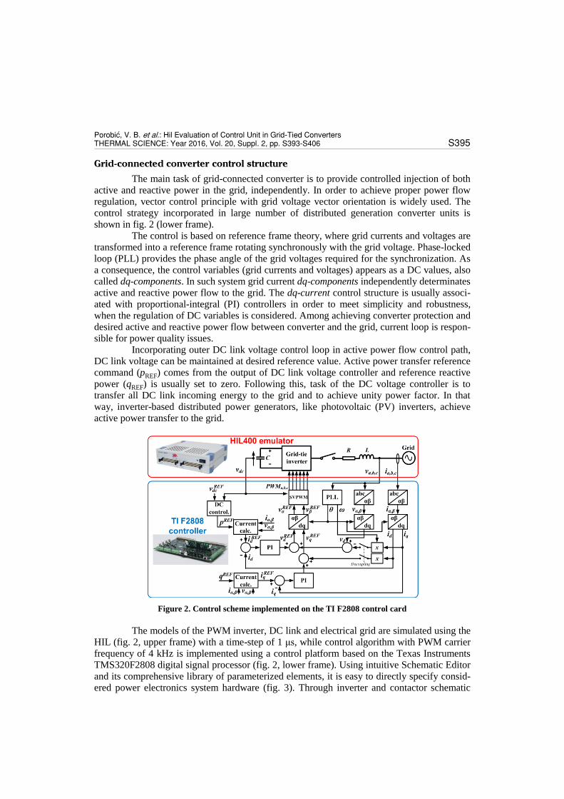
Grid-connected converter control structure
The main task of grid-connected converter is to provide controlled injection of both
active and reactive power in the grid, independently. In order to achieve proper power flow
regulation, vector control principle with grid voltage vector orientation is widely used. The
control strategy incorporated in large number of distributed generation converter units is
shown in fig. 2 (lower frame).
The control is based on reference frame theory, where grid currents and voltages are
transformed into a reference frame rotating synchronously with the grid voltage. Phase-locked
loop (PLL) provides the phase angle of the grid voltages required for the synchronization. As
a consequence, the control variables (grid currents and voltages) appears as a DC values, also
called dq-components. In such system grid current dq-components independently determinates
active and reactive power flow to the grid. The dq-current control structure is usually associ-
ated with proportional-integral (PI) controllers in order to meet simplicity and robustness,
when the regulation of DC variables is considered. Among achieving converter protection and
desired active and reactive power flow between converter and the grid, current loop is respon-
sible for power quality issues.
Incorporating outer DC link voltage control loop in active power flow control path,
DC link voltage can be maintained at desired reference value. Active power transfer reference
command (pREF) comes from the output of DC link voltage controller and reference reactive
power (qREF) is usually set to zero. Following this, task of the DC voltage controller is to
transfer all DC link incoming energy to the grid and to achieve unity power factor. In that
way, inverter-based distributed power generators, like photovoltaic (PV) inverters, achieve
active power transfer to the grid.
Figure 2. Control scheme implemented on the TI F2808 control card
The models of the PWM inverter, DC link and electrical grid are simulated using the
HIL (fig. 2, upper frame) with a time-step of 1 μs, while control algorithm with PWM carrier
frequency of 4 kHz is implemented using a control platform based on the Texas Instruments
TMS320F2808 digital signal processor (fig. 2, lower frame). Using intuitive Schematic Editor
and its comprehensive library of parameterized elements, it is easy to directly specify consid-
ered power electronics system hardware (fig. 3). Through inverter and contactor schematic
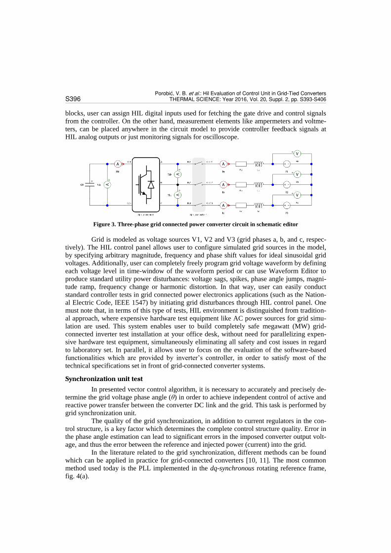
Porobi}, V. B. et al.: Hil Evaluation of Control Unit in Grid-Tied Converters S396 THERMAL SCIENCE: Year 2016, Vol. 20, Suppl. 2, pp. S393-S406
blocks, user can assign HIL digital inputs used for fetching the gate drive and control signals
from the controller. On the other hand, measurement elements like ampermeters and voltme-
ters, can be placed anywhere in the circuit model to provide controller feedback signals at
HIL analog outputs or just monitoring signals for oscilloscope.
Figure 3. Three-phase grid connected power converter circuit in schematic editor
Grid is modeled as voltage sources V1, V2 and V3 (grid phases a, b, and c, respec-
tively). The HIL control panel allows user to configure simulated grid sources in the model,
by specifying arbitrary magnitude, frequency and phase shift values for ideal sinusoidal grid
voltages. Additionally, user can completely freely program grid voltage waveform by defining
each voltage level in time-window of the waveform period or can use Waveform Editor to
produce standard utility power disturbances: voltage sags, spikes, phase angle jumps, magni-
tude ramp, frequency change or harmonic distortion. In that way, user can easily conduct
standard controller tests in grid connected power electronics applications (such as the Nation-
al Electric Code, IEEE 1547) by initiating grid disturbances through HIL control panel. One
must note that, in terms of this type of tests, HIL environment is distinguished from tradition-
al approach, where expensive hardware test equipment like AC power sources for grid simu-
lation are used. This system enables user to build completely safe megawatt (MW) grid-
connected inverter test installation at your office desk, without need for parallelizing expen-
sive hardware test equipment, simultaneously eliminating all safety and cost issues in regard
to laboratory set. In parallel, it allows user to focus on the evaluation of the software-based
functionalities which are provided by inverter’s controller, in order to satisfy most of the
technical specifications set in front of grid-connected converter systems.
Synchronization unit test
In presented vector control algorithm, it is necessary to accurately and precisely de-
termine the grid voltage phase angle (θ) in order to achieve independent control of active and
reactive power transfer between the converter DC link and the grid. This task is performed by
grid synchronization unit.
The quality of the grid synchronization, in addition to current regulators in the con-
trol structure, is a key factor which determines the complete control structure quality. Error in
the phase angle estimation can lead to significant errors in the imposed converter output volt-
age, and thus the error between the reference and injected power (current) into the grid.
In the literature related to the grid synchronization, different methods can be found
which can be applied in practice for grid-connected converters [10, 11]. The most common
method used today is the PLL implemented in the dq-synchronous rotating reference frame,
fig. 4(a).

Porobi}, V. B. et al.: Hil Evaluation of Control Unit in Grid-Tied Converters THERMAL SCIENCE: Year 2016, Vol. 20, Suppl. 2, pp. S393-S406 S397
Figure 4. (a) Conventional dq-PLL system block diagram; (b) Vector diagram of grid-connected converter variables in dq-reference frame
It contains filter, usually proportional-integral type, that determines PLL dynamic.
Error signal (e) is formed by subtracting the reference grid voltage q-component (uqgref
) set to
zero, and actual grid voltage q-component (uqg) obtained using estimated angle ( ) The PI
controller will act to reduce the error (e) to zero, which would lead to equalization of estimat-
ed phase angle and actual grid voltage phase angle, in steady-state. Thus, grid voltage d-
component (udg) is equal to grid voltage amplitude (ug), and rotating reference frame is
aligned with grid voltage vector, fig. 4(b). Normalization block (1/udg) is introduced in order
to avoid gain loss and instability during grid voltage sags.
Especially, PLL is influenced by presence of unbalance, harmonic distortion and
measurement offsets in the grid voltages. Therefore, filter bandwidth have to be carefully
designed as a compromise between filtering undesirable harmonics that occur in the PLL
control system due to the voltage distortion, and fast response time necessary for tracking
voltage during a frequency changes or voltage sags in the grid. For critical-aperiodic PLL
response parameters have to be set to values [11, 12]:
(1)
where ωbw is desired PLL system bandwidth. For desired frequency bandwidth of 3 Hz, ex-
pected settling time of PLL angle response would be around 1 second.
Experimental results
In order to examine PLL operation in ideal grid voltage conditions, grid voltages (V1,
V2, and V3) could be easily defined as balanced three-phase sine waveforms (230 Vrms/50 Hz)
in HIL control panel. In a case of PLL dynamic behavior test, waveform generator was used
to produce standard disturbance in form of grid voltage phase jump. Input value of 180° was
set as desired phase jump and one of the HIL digital outputs was used to trigger oscilloscope
and data capturing on the controller, fig. 5(a). Recorded results showing relevant variables in
the controller for PLL evaluation are given in fig. 5(b): grid voltage q-component (vqg) is
equal to 0, and d-component (vdg) is equal to the grid voltage amplitude 0.433 p. u., before
grid voltage phase jump and after the transient response (controller voltage base value is 750
V). That indicates proper PLL operation in steady-state. It can be concluded that the grid volt-
age components are DC values, which is a consequence of the chosen control strategy. Transi-
(a) (b)
Porobi}, V. B. et al.: Hil Evaluation of Control Unit in Grid-Tied Converters S398 THERMAL SCIENCE: Year 2016, Vol. 20, Suppl. 2, pp. S393-S406
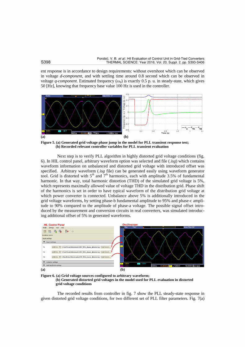
ent response is in accordance to design requirements: without overshoot which can be observed
in voltage d-component, and with settling time around 0.8 second which can be observed in
voltage q-component. Estimated frequency (ωg) is exactly 0.5 p. u. in steady-state, which gives
50 [Hz], knowing that frequency base value 100 Hz is used in the controller.
(a) (b)
Figure 5. (a) Generated grid voltage phase jump in the model for PLL transient response test; (b) Recorded relevant controller variables for PLL transient evaluation
Next step is to verify PLL algorithm in highly distorted grid voltage conditions (fig.
6). In HIL control panel, arbitrary waveform option was selected and file (.isg) which contains
waveform information on unbalanced and distorted grid voltage with introduced offset was
specified. Arbitrary waveform (.isg file) can be generated easily using waveform generator
tool. Grid is distorted with 5th and 7
th harmonics, each with amplitude 3.5% of fundamental
harmonic. In that way, total harmonic distortion (THD) of the simulated grid voltage is 5%,
which represents maximally allowed value of voltage THD in the distribution grid. Phase shift
of the harmonics is set in order to have typical waveform of the distribution grid voltage at
which power converter is connected. Unbalance above 5% is additionally introduced in the
grid voltage waveforms, by setting phase-b fundamental amplitude to 95% and phase-c ampli-
tude to 90% compared to the amplitude of phase-a voltage. The possible signal offset intro-
duced by the measurement and conversion circuits in real converters, was simulated introduc-
ing additional offset of 5% in generated waveforms.
(a) (b)
Figure 6. (a) Grid voltage sources configured to arbitrary waveform; (b) Generated distorted grid voltages in the model used for PLL evaluation in distorted grid voltage conditions
The recorded results from controller in fig. 7 show the PLL steady-state response in
given distorted grid voltage conditions, for two different set of PLL filter parameters. Fig. 7(a)
Fre
quen
cy (
p. u.)
: V
olt
age
(p. u.)

Porobi}, V. B. et al.: Hil Evaluation of Control Unit in Grid-Tied Converters THERMAL SCIENCE: Year 2016, Vol. 20, Suppl. 2, pp. S393-S406 S399
shows estimated grid voltage angle (θg), estimated grid voltage frequency (ωg), and measured
grid phase-a voltage (vag) for set PLL bandwidth of 3 Hz, and fig. 7(b) shows the same variables
for the case of 50 Hz bandwidth. It should be noted how important is to properly design PLL
filter parameters in order to attenuate possible harmonics propagation through PLL system re-
gard to grid voltage distortion. In case of designed PLL bandwidth of 50 Hz, it cannot appropri-
ately reject grid voltage distortion influence which can be best observed in estimated frequency.
One can note 50 Hz, 100 Hz, and 300 Hz harmonic components in estimated frequency variable
(ωg), producing estimated angle signal (θg) which significantly deviates from pure ramp wave-
form.
(a) (b)
Figure7. PLL steady-state response in distorted grid voltage conditions: (a) for designed bandwidth of 3 Hz; (b) for designed bandwidth of 50 Hz
Current control loop test
In order to implement current control, mathematical model of grid-connected con-
verter will be introduced here. Electrical circuit of the system is shown in fig. 8. Equations in
original phase domain can be easily transformed in the stationary reference frame () and
synchronously rotating (dq) frame, rotating at PLL estimated frequency (ωG). Absolute varia-
bles can be transferred in normalized (relative) domain using selected and derived base val-
ues. If the PLL places grid voltage space vector in the d-axis of rotating frame, state space
model of the system is given by eq. (2)-(8).
(2)
(3)
(4)
(5)
(6)
(7)
where variable τS is grid equivalent time-constant
(8)
and all the rest variables are normalized representatives of their absolute values (
).
Angle
(p. u.)
; F
requen
cy (
p. u.)
;
Volt
age
(p. u.)
Angle
(p. u.)
; F
requen
cy (
p. u.)
;
Volt
age
(p. u.)

Porobi}, V. B. et al.: Hil Evaluation of Control Unit in Grid-Tied Converters S400 THERMAL SCIENCE: Year 2016, Vol. 20, Suppl. 2, pp. S393-S406
Energysource
ex.
Couplinginductance
Grid
Power converter
DC
ugus
xs , rs
i
Figure 8. Grid-connected converter and simplified electrical representation
According to the voltage eqs. (2) and (3), it should be noted that cross-coupling terms
are present between dq-axes. Therefore, decoupling scheme shown in fig. 9, with eqs. (9) and
(10) have to be applied in current control structure. Transformation angle is obtained
from grid synchronization unit and it was discussed before in detail.
PIid
udSidref
Current controller
id
udSref
-wGestlsiq+udG
PIiq
uqSiqref
Current controller
iq
uqSref
wgestlsid
dq
Coordinate transformation
abc
idq
iabc
qGest
PLL
Estimation
uGabc
udG
qGest
wGest
Figure 9. Grid-connected converter current control strategy
(9)
(10)
Figure 10 shows the control loop for current d-component after application of de-
coupling elements. Also, quadrature q-axis current loop has the same layout ( –
grid time constant, – sampling period). Thus, PI controller parameter values for both axes
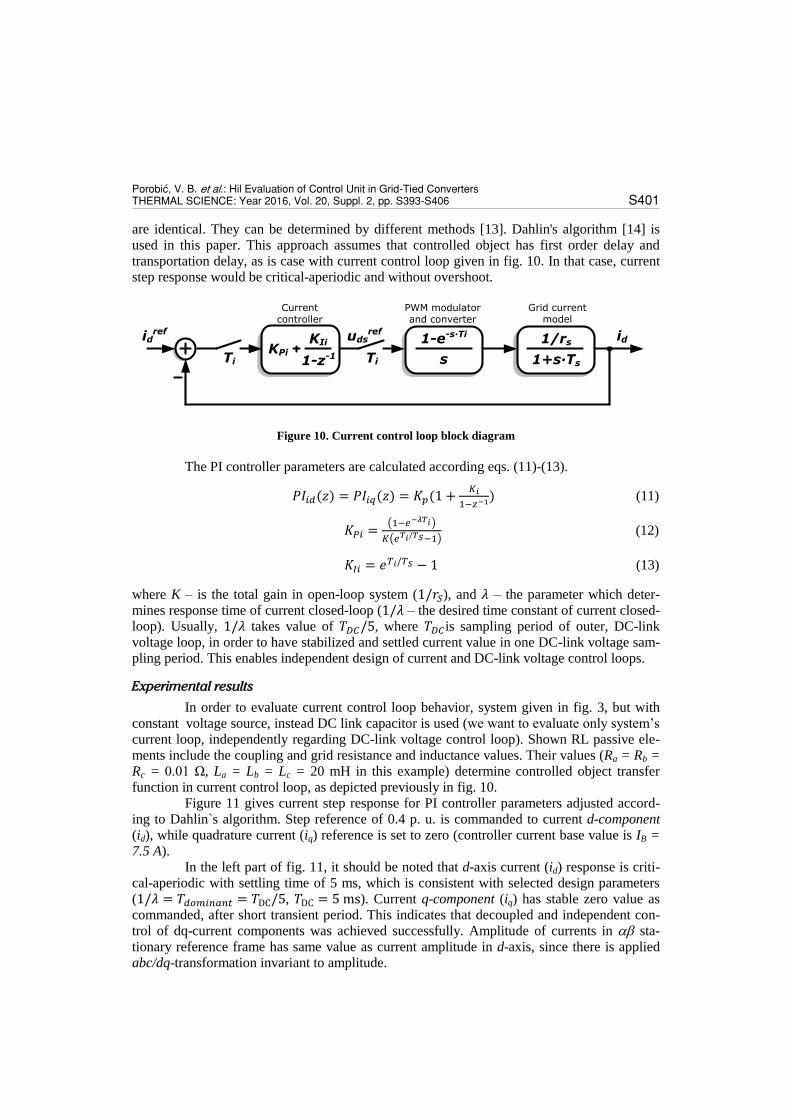
Porobi}, V. B. et al.: Hil Evaluation of Control Unit in Grid-Tied Converters THERMAL SCIENCE: Year 2016, Vol. 20, Suppl. 2, pp. S393-S406 S401
are identical. They can be determined by different methods [13]. Dahlin's algorithm [14] is
used in this paper. This approach assumes that controlled object has first order delay and
transportation delay, as is case with current control loop given in fig. 10. In that case, current
step response would be critical-aperiodic and without overshoot.
KPi
KIi
1-z-1
1-e-s∙Ti
s
1/rs
1+s∙TsTi Ti
udsrefid
ref id
PWM modulatorand converter
Current controller
Grid current model
Figure 10. Current control loop block diagram
The PI controller parameters are calculated according eqs. (11)-(13).
(11)
(12)
(13)
where K – is the total gain in open-loop system ( ), and – the parameter which deter-
mines response time of current closed-loop ( – the desired time constant of current closed-
loop). Usually, takes value of , where is sampling period of outer, DC-link
voltage loop, in order to have stabilized and settled current value in one DC-link voltage sam-
pling period. This enables independent design of current and DC-link voltage control loops.
Experimental results
In order to evaluate current control loop behavior, system given in fig. 3, but with
constant voltage source, instead DC link capacitor is used (we want to evaluate only system’s
current loop, independently regarding DC-link voltage control loop). Shown RL passive ele-
ments include the coupling and grid resistance and inductance values. Their values (Ra = Rb = Rc = 0.01 Ω, La = Lb = Lc = 20 mH in this example) determine controlled object transfer
function in current control loop, as depicted previously in fig. 10.
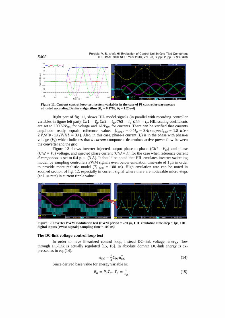
Figure 11 gives current step response for PI controller parameters adjusted accord-
ing to Dahlin`s algorithm. Step reference of 0.4 p. u. is commanded to current d-component (id), while quadrature current (iq) reference is set to zero (controller current base value is IB = 7.5 A).
In the left part of fig. 11, it should be noted that d-axis current (id) response is criti-
cal-aperiodic with settling time of 5 ms, which is consistent with selected design parameters
( , ). Current q-component (iq) has stable zero value as
commanded, after short transient period. This indicates that decoupled and independent con-
trol of dq-current components was achieved successfully. Amplitude of currents in sta-
tionary reference frame has same value as current amplitude in d-axis, since there is applied
abc/dq-transformation invariant to amplitude.
Porobi}, V. B. et al.: Hil Evaluation of Control Unit in Grid-Tied Converters S402 THERMAL SCIENCE: Year 2016, Vol. 20, Suppl. 2, pp. S393-S406
Figure 11. Current control loop test: system variables in the case of PI controller parameters adjusted according Dahlin`s algorithm (Kp = 0.1769, Ki = 1.25e-4)
Right part of fig. 11, shows HIL model signals (in parallel with recording controller
variables in figure left part): . HIL scaling coefficients
are set to 100 V/VHIL for voltage and 1A/VHIL for currents. There can be verified that currents
amplitude really equals reference values ( ). Also, in this case, phase-a current (Ia) is in the phase with phase-a
voltage (Va) which indicates that d-current component determines active power flow between
the converter and the grid.
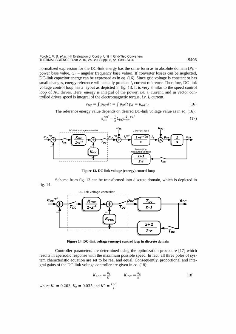
Figure 12 shows inverter injected output phase-to-phase (Ch1 =Vab) and phase
(Ch2 = Va) voltage, and injected phase current (Ch3 = Ia) for the case when reference current
d-component is set to 0.4 p. u. (3 A). It should be noted that HIL emulates inverter switching
model, by sampling controllers PWM signals even below emulation time-rate of 1 μs in order
to provide more realistic model (Ts_pwm = 100 ns). High emulation rate can be noted in
zoomed section of fig. 12, especially in current signal where there are noticeable micro-steps
(at 1 μs rate) in current ripple value.
Figure 12. Inverter PWM modulation test (PWM period = 250 μs, HIL emulation time-step = 1μs, HIL
digital inputs (PWM signals) sampling time = 100 ns)
The DC-link voltage control loop test
In order to have linearized control loop, instead DC-link voltage, energy flow
through DC-link is actually regulated [15, 16]. In absolute domain DC-link energy is ex-
pressed as in eq. (14).
(14)
Since derived base value for energy variable is:
(15)
Curr
ent
(p.
u.)
Porobi}, V. B. et al.: Hil Evaluation of Control Unit in Grid-Tied Converters THERMAL SCIENCE: Year 2016, Vol. 20, Suppl. 2, pp. S393-S406 S403
normalized expression for the DC-link energy has the same form as in absolute domain (PB –
power base value, ωB – angular frequency base value). If converter losses can be neglected,
DC-link capacitor energy can be expressed as in eq. (16). Since grid voltage is constant or has
small changes, energy reference will actually produce id current reference. Therefore, DC-link
voltage control loop has a layout as depicted in fig. 13. It is very similar to the speed control
loop of AC drives. Here, energy is integral of the power, i.e. id current, and in vector con-
trolled drives speed is integral of the electromagnetic torque, i.e. iq current.
(16)
The reference energy value depends on desired DC-link voltage value as in eq. (16):
(17)
TDC
eDCref
KIDC
1-z-1
KPDC
TDC
1-e-s∙T
s s
1
TDC
z+1
2∙z
udG udG
pDCref id
ref id pDC eDC
DC-link voltage controller id current loop
Averaging measured voltage
DC
Figure 13. DC-link voltage (energy) control loop
Scheme from fig. 13 can be transformed into discrete domain, which is depicted in
fig. 14.
z+1
2∙z
TDC
eDCref
KIDC
1-z-1
KPDC
TDC
TDC
z-1
pDCref eDC
DC-link voltage controller
TDC
Figure 14. DC-link voltage (energy) control loop in discrete domain
Controller parameters are determined using the optimization procedure [17] which
results in aperiodic response with the maximum possible speed. In fact, all three poles of sys-
tem characteristic equation are set to be real and equal. Consequently, proportional and inte-
gral gains of the DC-link voltage controller are given in eq. (18):
(18)
where , and
.

Porobi}, V. B. et al.: Hil Evaluation of Control Unit in Grid-Tied Converters S404 THERMAL SCIENCE: Year 2016, Vol. 20, Suppl. 2, pp. S393-S406
Experimental results
Figure 15 shows step response of DC-link voltage control loop. Test circuit emulat-
ed in the HIL is the same as in fig. 3 (DC link capacitor C = 1000 μF). DC-link voltage step
reference is commanded from 0.866 p. u. (default initial value of capacitor voltage is set to
650 V, and controller base voltage is set to UB = 750 V) to 0.95 p. u. (712.5 V), while reactive
power reference is set to zero.
On the left part of fig. 15, it should be noted that DC-link voltage reference is
achieved with no overshoot. In order to charge capacitor to new reference value higher then
initial, active power flow from the grid to the converter (i. e. it has negative value during tran-
sition process), while reactive power is zero as commanded.
On the right part of fig. 15 relevant HIL model variables for testing DC-link control
loop are observed by scope: . Used HIL scaling
coefficients are 100 V/VHIL for voltage , 150 V/VHIL for voltage and 1 A/VHIL for in-
verter, i. e. grid currents. There can be concluded that phase currents are equal to zero before
and at the end of the transition process, indicating stable DC-link voltage value. During transi-
tion process, one can note that grid currents have inverse phase compared to corresponding
grid phase voltages, indicating active power flow in direction from the grid to the converter
DC-link.
Figure 15. DC-link voltage control loop test: reference step response
In order to evaluate DC-link voltage control loop disturbance rejection, system given
in fig. 3 with ideal current source which models desired disturbance (flowing into inverter
DC+ point) instead DC link capacitor is used. The HIL actually enables user to evaluate com-
plete PV inverter system, by replacing current source with PV panel model (with e. g. boost
converter), or complete energy storage system, by replacing current source with battery mod-
el.
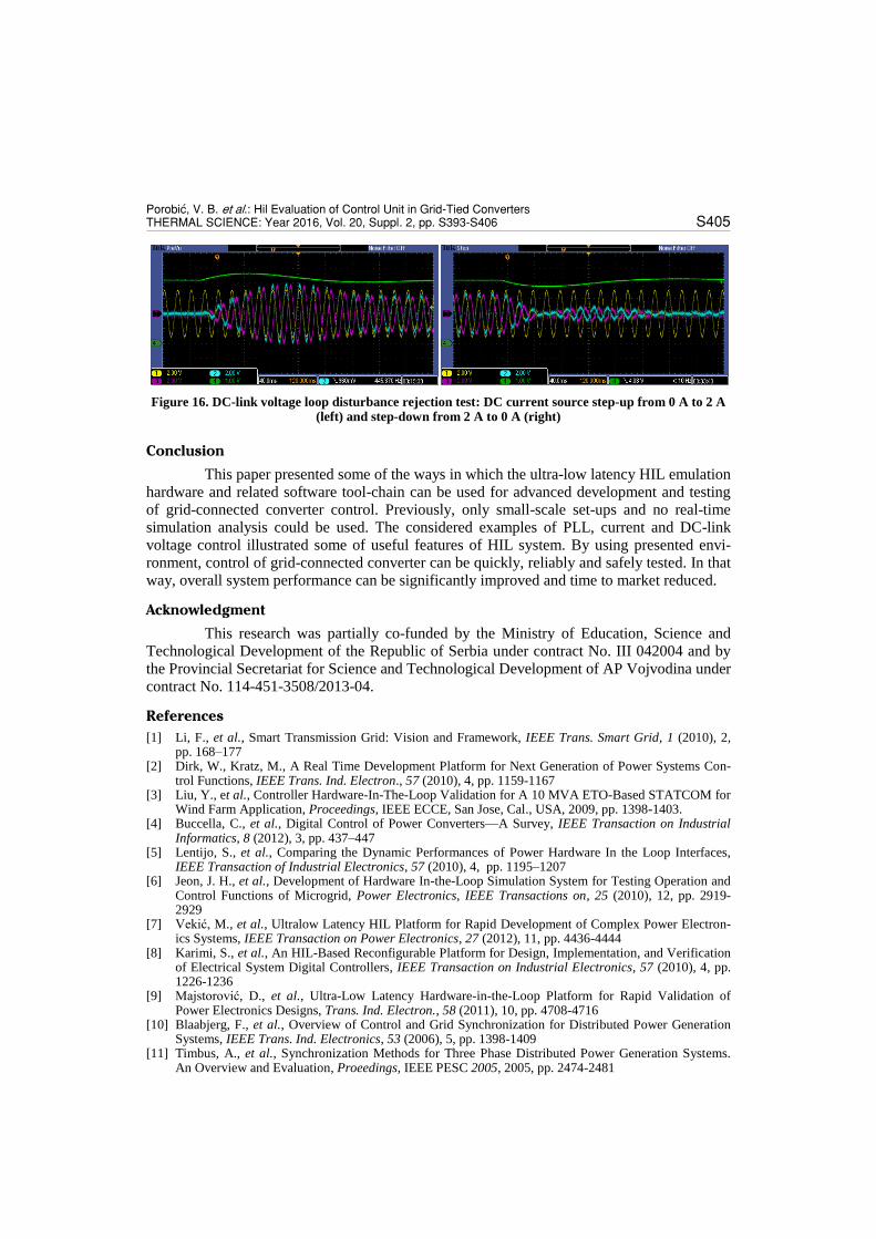
Figure 16 shows two cases for DC-link voltage control loop disturbance test. On the
left figure, signals are given for the occurrence when DC current source reference (I0) is set
from zero to 2 A, while right figure shows situation when current source reference is set from
2 A to zero ( . Used HIL scaling coefficients are
100V/VHIL for voltage , 150V/VHIL for voltage and 1A/VHIL for currents). DC-link voltage
control loop manages to keep this voltage to its default, constant nominal value 650 V. Grid
currents are zero when DC current has zero value, while they are in-phase (or with inverse
phase) with corresponding phase voltages when DC current has non-zero value, indicating
active power flow between the grid and the converter. During DC-link voltage steady-state,
all incoming energy from/to current source is supplied to/from the grid, which represents the
main task in the grid-connected converter applications.
Volt
age
(p. u.)
; P
ow
er (
p.
u.)
Porobi}, V. B. et al.: Hil Evaluation of Control Unit in Grid-Tied Converters THERMAL SCIENCE: Year 2016, Vol. 20, Suppl. 2, pp. S393-S406 S405
Figure 16. DC-link voltage loop disturbance rejection test: DC current source step-up from 0 A to 2 A (left) and step-down from 2 A to 0 A (right)
Conclusion
This paper presented some of the ways in which the ultra-low latency HIL emulation
hardware and related software tool-chain can be used for advanced development and testing
of grid-connected converter control. Previously, only small-scale set-ups and no real-time
simulation analysis could be used. The considered examples of PLL, current and DC-link
voltage control illustrated some of useful features of HIL system. By using presented envi-
ronment, control of grid-connected converter can be quickly, reliably and safely tested. In that
way, overall system performance can be significantly improved and time to market reduced.
Acknowledgment
This research was partially co-funded by the Ministry of Education, Science and
Technological Development of the Republic of Serbia under contract No. III 042004 and by
the Provincial Secretariat for Science and Technological Development of AP Vojvodina under
contract No. 114-451-3508/2013-04.
References
[1] Li, F., et al., Smart Transmission Grid: Vision and Framework, IEEE Trans. Smart Grid, 1 (2010), 2, pp. 168–177
[2] Dirk, W., Kratz, M., A Real Time Development Platform for Next Generation of Power Systems Con-trol Functions, IEEE Trans. Ind. Electron., 57 (2010), 4, pp. 1159-1167
[3] Liu, Y., et al., Controller Hardware-In-The-Loop Validation for A 10 MVA ETO-Based STATCOM for Wind Farm Application, Proceedings, IEEE ECCE, San Jose, Cal., USA, 2009, pp. 1398-1403.
[4] Buccella, C., et al., Digital Control of Power Converters—A Survey, IEEE Transaction on Industrial Informatics, 8 (2012), 3, pp. 437–447
[5] Lentijo, S., et al., Comparing the Dynamic Performances of Power Hardware In the Loop Interfaces, IEEE Transaction of Industrial Electronics, 57 (2010), 4, pp. 1195–1207
[6] Jeon, J. H., et al., Development of Hardware In-the-Loop Simulation System for Testing Operation and Control Functions of Microgrid, Power Electronics, IEEE Transactions on, 25 (2010), 12, pp. 2919-2929
[7] Vekić, M., et al., Ultralow Latency HIL Platform for Rapid Development of Complex Power Electron-ics Systems, IEEE Transaction on Power Electronics, 27 (2012), 11, pp. 4436-4444
[8] Karimi, S., et al., An HIL-Based Reconfigurable Platform for Design, Implementation, and Verification of Electrical System Digital Controllers, IEEE Transaction on Industrial Electronics, 57 (2010), 4, pp. 1226-1236
[9] Majstorović, D., et al., Ultra-Low Latency Hardware-in-the-Loop Platform for Rapid Validation of Power Electronics Designs, Trans. Ind. Electron., 58 (2011), 10, pp. 4708-4716
[10] Blaabjerg, F., et al., Overview of Control and Grid Synchronization for Distributed Power Generation Systems, IEEE Trans. Ind. Electronics, 53 (2006), 5, pp. 1398-1409
[11] Timbus, A., et al., Synchronization Methods for Three Phase Distributed Power Generation Systems. An Overview and Evaluation, Proeedings, IEEE PESC 2005, 2005, pp. 2474-2481

Porobi}, V. B. et al.: Hil Evaluation of Control Unit in Grid-Tied Converters S406 THERMAL SCIENCE: Year 2016, Vol. 20, Suppl. 2, pp. S393-S406
[12] Awad, H., et al., Tuning Software Phase-Locked Loop for Series-Connected Converters, IEEE Trans. Power Delivery, 20 (2005), 1, pp. 300-308
[13] Adžić, E., et al., HIL Evaluation of Current Control in Grid-Tie Converters, Proceedings, 6th PSU-UNS International Conference on Engineering and Technology (ICET-2013), Novi Sad, Serbia, 2013., No. T.12-1.2, pp. 1-5
[14] M. Stojić, Digitalni sistemi upravljanja, (Digital Control Systems, in Serbian), Akademska misao, Belgrade, Serbia, 2004., ISBN: 86-7466-139-4
[15] Porobić, V., et al., HIL Evaluation of DC-Link Voltage Control in Grid-Tie Converters, Proceedings, 6th PSU-UNS International Conference on Engineering and Technology (ICET-2013), Novi Sad, Serbia, 2013., No. T.12-1.3, pp. 1-5
[16] Dumnić, B., et al., Control of Grid Connected Converter with Improved Power Quality Characteristic, Proceedings, PCIM Europe 2015, International Exhibition and Conference for Power Electronics, Intel-ligent Motion, Renewable Energy and Energy Management, 2015, pp.1-8
[17] Vukosavic, S., Digital Control of Electrical Drives, Springer 2007, ISBN-13: 978-1441938541.
Paper submitted: September 28, 2015 Paper revised: December 4, 2015 Paper accepted: December 23, 2015