Embed Size (px)
Citation preview

Worcestershire Local Transport Plan 3
Find out more online:www.worcestershire.gov.uk/LTP3
Worcestershire Local Transport Plan 3
Find out more online:www.worcestershire.gov.uk
Highways Specification
Find out more online:www.worcestershire.gov.uk/LTP3


1.1 Scope of the Specification ................................................................................................................................................ 1
1.2 Substitute and Additional Clauses ................................................................................................................................. 1
1.3 Breaking Open Existing Highway ..................................................................................................................................... 1
1.4 Typical Test and Supervision Procedure .................................................................................................................... 2
1.5 Works Adjacent to Existing Highway Structures .................................................................................................... 2
1.6 Subcontracting of the Works .......................................................................................................................................... 2
1.7 Approval of Drawings Prior to Commencement of the Works ...................................................................... 3
1.8 Commencement of the Works ...................................................................................................................................... 3
1.9 Works to be to the Director of Environmental Services Satisfaction .......................................................... 3
1.10 Variation of the Works ....................................................................................................................................................... 3
1.11 Access to the Works ........................................................................................................................................................... 3
1.12 Signing, Guarding and Lighting ........................................................................................................................................4
1.13 Mud and Other Debris on the Highway .....................................................................................................................4
1.14 Pollution and Obstruction of Watercourses and Sewers...................................................................................4
1.15 Removal of Improper Materials and Workmanship ..............................................................................................4
1.16 Making Good Damage to Existing Highway .............................................................................................................. 5
1.17 Land Drains ............................................................................................................................................................................... 5
1.18 Archaeological Interests .................................................................................................................................................... 5
1.19 Health and Safety File ........................................................................................................................................................ 6
1.20 CCTV Surveys......................................................................................................................................................................... 6
1.21 Design Considerations ........................................................................................................................................................ 7
1.22 Design of Construction Thickness ................................................................................................................................. 7
1.23 Safety Requirements ........................................................................................................................................................... 7
1.24 Notification of Emergency Telephone Numbers .................................................................................................. 8
1.25 Preliminary Site Works ...................................................................................................................................................... 8
1.26 Developers Obligations ..................................................................................................................................................... 9
1.27 General Construction Requirements .......................................................................................................................... 9
1.28 Surface Regularity and Tolerances .............................................................................................................................. 10
1.29 Construction and Earthworks Materials .................................................................................................................... 11
1.30 Concrete for Ancillary Purposes .................................................................................................................................. 12
2.1 Topsoil Stripping ................................................................................................................................................................. 13

2.2 Excavation to Formation.................................................................................................................................................. 13
2.3 Areas Below Formation .................................................................................................................................................... 13
2.4 Forming Areas of Fill .......................................................................................................................................................... 13
2.5 Granular Material Backfill ................................................................................................................................................ 14
2.6 Backfill Materials and Construction Depths ........................................................................................................... 14
3.1 Earthworks Operations ..................................................................................................................................................... 15
3.2 Construction ......................................................................................................................................................................... 15
4.1 Shaping and Compaction ................................................................................................................................................ 17
4.2 Weather Protection ........................................................................................................................................................... 17
4.3 Geotextile Requirement .................................................................................................................................................. 17
4.4 Shared Surface, Access Roads and Industrial Estate Roads ............................................................................. 17
4.5 Drainage of Sub Grade ..................................................................................................................................................... 17
5.1 General ..................................................................................................................................................................................... 19
5.2 Sub Formation and Capping ........................................................................................................................................... 19
5.3 Capping Material ................................................................................................................................................................. 19
5.4 Sub Base Materials .............................................................................................................................................................. 19
6.1 Concrete ................................................................................................................................................................................. 21
6.2 Concrete Aggregates ......................................................................................................................................................... 21
6.3 Storage of Concrete Aggregates ................................................................................................................................. 21
6.4 Cement .................................................................................................................................................................................... 21
6.5 Rapid Hardening Cement ................................................................................................................................................ 21
6.6 Sand ........................................................................................................................................................................................... 21
6.7 Water ........................................................................................................................................................................................ 21
6.8 Grout ........................................................................................................................................................................................ 21
7.1 General .................................................................................................................................................................................... 23
7.2 Bituminous Materials ........................................................................................................................................................ 23
7.3 Dense Bitumen Macadam-Base Layer ....................................................................................................................... 23
7.4 Dense Bitumen Macadam-Binder Layer ................................................................................................................... 23
7.5 High Stone Copntent Asphalt-Surface Course .................................................................................................... 23
7.6 Concrete Block Paving ..................................................................................................................................................... 23

8.1 Kerb Race and Backing ..................................................................................................................................................... 25
8.2 Kerbs - General Requirements ..................................................................................................................................... 25
8.3 Radius Kerb Lines ................................................................................................................................................................ 25
8.4 Blockwork Kerbs ................................................................................................................................................................. 25
9.1 General Requirements ..................................................................................................................................................... 27
9.2 Spacing of Gullies ............................................................................................................................................................... 27
9.3 Ironwork within Cycleways/Footways ..................................................................................................................... 27
10.1 General requirements - Type and Size (Refer to Standard Detail Appendix E) ..................................... 29
10.2 Bedding and Surround ..................................................................................................................................................... 29
11.1 General Requirements ...................................................................................................................................................... 31
11.2 Surface Water Pipes ........................................................................................................................................................... 31
11.3 Concrete Surround to Pipes .......................................................................................................................................... 31
11.4 Soakaways ............................................................................................................................................................................. 32
11.5 Prior to Adoption ............................................................................................................................................................... 32
12.1 General Requirements (Refer to Standard Details in Appendix E) .............................................................. 33
12.2 Bedding ................................................................................................................................................................................... 33
12.3 Skid Resistance of Inspection Chamber Covers .................................................................................................. 33
13.1 General Requirements ..................................................................................................................................................... 35
14.1 Preparation ............................................................................................................................................................................ 37
14.2 Footway/Footpath/Cycleway - Base ....................................................................................................................... 37
14.3 Footway/Footpath/Cycleway - Binder Course ................................................................................................... 37
14.4 Footway/Footpath/Cycleway - Surface Course ................................................................................................. 37
14.5 Crossfalls ................................................................................................................................................................................ 37
14.6 Edge Supports ...................................................................................................................................................................... 37
15.1 Vehicular Crossings ........................................................................................................................................................... 39
15.2 Pedestrian Crossings ......................................................................................................................................................... 39
15.3 Cycle Crossings ................................................................................................................................................................... 39
15.4 Construction Depths ........................................................................................................................................................ 39

15.5 Dropped Kerbs and Alignments .................................................................................................................................. 39
16.1 Seeding and Turfing - General....................................................................................................................................... 41
16.2 Initial Ground Preparation .............................................................................................................................................. 41
16.3 Fertilizer Application ......................................................................................................................................................... 41
16.4 Seeding .................................................................................................................................................................................... 41
16.5 Turfing ..................................................................................................................................................................................... 42
16.6 Maintenance of Seeded Areas ..................................................................................................................................... 42
16.7 Maintenance of Turfed Areas ...................................................................................................................................... 42
16.8 Overseeding ......................................................................................................................................................................... 42
16.9 Edge Support Delineation .............................................................................................................................................. 42
17.1 Introduction ......................................................................................................................................................................... 43
17.2 Procedures Summary ....................................................................................................................................................... 44
17.3 Method 1 ................................................................................................................................................................................ 44
17.4 Setting Out Column Positions ..................................................................................................................................... 45
17.5 Installation ............................................................................................................................................................................. 45
17.6 Electrical Testing ................................................................................................................................................................. 46
17.7 Inspections by Worcestershire County Council .................................................................................................. 46
17.8 Additional Developer Responsibilities ..................................................................................................................... 47
17.9 Charges by the County Council .................................................................................................................................. 47
17.10 Method 2 ............................................................................................................................................................................... 48
17.11 Design Considerations ..................................................................................................................................................... 48
17.12 Design Requirements ........................................................................................................................................................ 49
17.13 Highway Lighting Equipment Requirements and Installation Standards. ................................................. 52
17.14 Setting Out Column Positions ..................................................................................................................................... 54
17.15 Electrical Testing ................................................................................................................................................................. 54
17.16 Inspections by Worcestershire County Council .................................................................................................. 54
17.17 Additional Developer Responsibilities ..................................................................................................................... 55
17.18 Charges by the County Council .................................................................................................................................. 55


i
The Authority shall mean: Worcestershire County Council.
The Developer shall mean: The Person, Persons or Firm or Company as defined in the Agreement.
The Agreement shall mean: The Agreement under Section 38 or Section 278 of the Highways Act, 1980 agreed and entered into between the Authority and the Developer.
The Specification shall mean: Worcestershire County Council’s Highways Specification for New Developments.
Director of Environmental Services shall Mean: Mr John Hobbs, Director of Environmental Services, County Hall, Spetchley Road, Worcester WR5 2NP or his appointed representative.
The Works shall mean: The Permanent Construction Works to be executed in accordance with this Specification as detailed on the Drawings and as defined in the Agreement.
The Drawing shall mean: The Plans Section and Details (and any subsequent amendment thereto) approved by the Director of Environmental Services and referred to in and attached to the Agreement.
The Site shall mean: The Lands owned by the Developer and the Minimum extent of such Public Highways and Public and Private Lands, which in the opinion of the Director of Environmental Services is necessary and practicable for the proper construction of the Works.
Approved Directed and Instructed shall mean: Approved, Directed and Instructed by the Director of Environmental Services.
B.S. shall mean: The relevant British Standard current at the time of the execution of the Works.
Sewer shall mean: Sewers, Culverts and Drains of all descriptions (except sub-soil drains) whether for the conveyance of foul sewerage, storm water or surface water.
Department of Transport Specification shall mean: Latest Edition of the Department of Transport Specification for Highways Works hereafter called DoT SHW.
Technical Approval for Highway Structure shall mean: The procedures for technical approval of all highway structures as required by the Director of Environmental Services.
The Testing Consultant: A laboratory accredited by UKAS for the required tests or otherwise approved by the Director of Environmental Services.
California Bearing Ratio (CBR): A value derived from a standard test indicating the ratio of the strength of a particular soil compared with the corresponding strength of crushed rock.
Subgrade: Existing natural ground at and below formation.
Formation: The level from which construction commences.
Carriageway: The surfaced area of the road designed primarily for the passage of vehicles.
Highway: A route where traffic has the right to pass. It may be restricted to particular classes of vehicles. The highway consists of the carriageway, cycleway and footway surfaces and includes any verges or vision splays.
Manhole: A chamber constructed at specified intervals along drainage lines to allow access for cleaning or maintenance.
Gully: An open topped pot usually made of concrete constructed at the carriageway edge to drain water from the carriageway. The aperture at the top of the gully is covered with a cast iron grating.

ii
Channel: A narrow strip usually placed at the edge of the carriageway designed to transfer surface water.
Cycleway: The part of the carriageway over which cyclists have right of way.
Footpath: A highway over which the public has right of way on foot only. It is remote from the carriageway.
Footway: The part of the highway adjacent to the carriageway and is a right of way on foot only.

1.1.1 This specification refers and applies to the design and construction of highways and highway
infrastructure constructed by or on behalf of a private Developer where the Council as the
Highway Authority will, undertake to adopt the highways and highway infrastructure as
highways and highway infrastructure maintainable by the Authority at public expense, at the
end of the maintenance period and following inspection and satisfactory completion of
works.
1.2.1 Where any Works proposed to be undertaken by a Developer are deemed by the Director of
Environmental Services not to be covered by the various Clauses of this Specification then
the Director of Environmental Services shall, where he considers it desirable or necessary,
issue, substitute or include additional Clauses and all details, drawings, substitutions and
additional Clauses so issued shall be read and construed as forming part of this.
1.3.1 Where it is necessary to break open an existing highway to lay or maintain apparatus, the
Developer is required, under Section 50 the New Roads and Street Works Act 1991, to give
prior notice to the Highway Authority. Six week's notice must be given.
Under the CDM Regulations the Developer is regarded as the Client, anyone who has any input to the
design process is regarded as a Designer and the Client must appoint a Planning co-ordinator to
oversee the key procedural stages. All of these roles within CDM have clear and specific responsibilities
and obligations.
Personnel working in the Highway should possess NRSWA accreditation for their function.
The Developer shall comply with the Control of Pollution Act, Land Drainage Act and Environmental
Protection Act in preventing the pollution or blocking of water supplies, watercourses. Contaminated
land shall be suitably remediated and hazardous waste disposed of in compliance with current
legislation and recorded within the CDM Health and Safety file.
On-site wheel washing equipment is normally stipulated as part of the Planning Consent and the Highway Agreement.
Any signing, temporary or permanent shall be illuminated so as not to dazzle, cause distraction or glare.
Prevention of Noise shall be in accordance with current best practice and the provisions of the Control of Pollution Act 1974 and any working times specified in the Planning Consent.
Dust, smoke and the arising from any cutting, sawing, grinding and drilling operations shall be contained or suppressed to ensure that no dust or debris escapes as air-born pollution.

1.3.2 All works within the highway must comply with the Traffic Management Act (TMA)
notification requirements. Developers must be aware that standard notification period is
three months; therefore notification must be made to the Highway Authority at an
appropriate time to avoid delays.
1.3.3 No work shall be carried out in the public highway until such notices have been received and
approved.
1.4.1 (Refer to Appendix B1, B2 & B3)
1.5.1 No Works shall be carried out adjacent or at the approaches to, below, or through, on, or
over any existing highway structure without the written permission of the Director of
Environmental Services. Such permission will be withheld where the Director of
Environmental Services considers the Works or the manner in which the Works are proposed
to be carried out may endanger the structural condition, stability or safety of the structure.
1.6.1 Should the Developer appoint or intend to appoint any other person, persons, Firm or
Company to construct the Works (or any part thereof) on his behalf then he shall, not less
than seven days prior to the commencement of the Works submit to the Director of
Environmental Services in writing the name, office, address and 24 hour telephone number of
the person, persons, Firm or Company to whom or to which the Works (or any part thereof)
will be assigned.
1.6.2 Sub-contracting of the construction of the Works (or any part thereof) shall not in any way
relieve the Developer from his obligations and liabilities under the terms of the Agreement
and he shall be responsible for the acts, defaults and neglects of the person, persons, Firms or
Company to whom or to which the Works (or any part thereof) have been assigned including
their agents, servants or workmen as fully as if they were the acts, defaults and neglects of
the Developer, his agents or workmen.

1.7.1 The Developer shall not commence construction of the works until he is advised in writing by
the Director of Environmental Services that the Drawings and Documents including all details
contained therein are sufficient and satisfactory in all respects, and that the arrangements
and negotiations in respect of the Agreement are satisfactory or have been completed and
concluded and the Agreements entered into.
1.8.1 The Developer shall not less than seven days prior to the commencement of the Works and
after serving all required notices and gaining necessary permission, advise the Director of
Environmental Services in writing of his intention to commence the Works. Work shall not
proceed without the Construction Phase Health and Safety file being in place with the
necessary Authorities.
1.8.2 The Developer shall not discontinue the Works without prior approval of the Director of
Environmental Services and shall where such approval is given, notify the Director in writing
of his intentions for securing, safeguarding and protecting the partially completed Works and
indicating the anticipated period of cessation. The Developer shall give not less than seven
days notice in writing to the Director of Environmental Services of his intention to
recommencement the Works.
1.9.1 The Developer shall execute, complete and maintain the Works in strict accordance with the
requirements of this Specification to the satisfaction of the Director of Environmental
Services and shall comply fully with and adhere strictly to the directions and instructions of
the Director of Environmental Services.
1.9.2 The decisions of the Director of Environmental Services in respect of the requirements,
provisions and interpretations of these General Conditions and Specification shall be final
and binding.
1.10.1 No variation of the position, alignment, dimensions, levels or construction details of the
Works shall be made without the written consent of the Director of Environmental Services.
1.11.1 The Director of Environmental Services and any other persons authorised by the Director of
Environmental Services shall at all times have access to the Works.

1.12.1 The Developer shall provide and maintain any necessary watching and lighting, temporary
barricades, traffic control, etc., as required for the safe execution of the Works. For
emergency use outside normal working hours, the Developer shall prior to the
commencement of the Works, provide the Director of Environmental Services in writing with
the name, daytime and night-time telephone numbers and address of the person responsible
for site security and traffic safety and control. The Developers must obtain the approval of
the Director of Environmental Services before using any temporary signals on the existing
highway.
1.13.1 The Developer is reminded that it is an offence under the Highways Act 1980 to deposit or
allow materials to be washed onto a Highway and should therefore take all reasonable steps
to ensure that the Highway is kept clear of all mud, clay, lime or similar material during the
execution of the project. It may be necessary to provide wheel washing facilities to ensure
that all vehicles leaving the site are sufficiently clean to ensure that no materials are
deposited on the Highway.
1.13.2 The existing public highway must not be used for stockpiling or storing plant, materials or
equipment. The use of the existing publicly maintained Highway by plant and machinery is
likely to cause damage to the Highway and the Developer/Contractor will be liable for the
cost of the reinstatement under Section 59 of the Highways Act 1980 if any damage has been
caused to the Highway.
1.14.1 The Developer shall not during the construction and maintenance of the Works allow any
naturally occurring materials, construction, and building materials, chemical, poisonous and
inflammable substances, obnoxious solid, gasses or fluids, sewage or other organic and
inorganic impurities to be discharged from the Works and cause pollution or obstruction to
any canal, river, watercourse, ditch or surface water sewers and drains.
1.14.2 Should the Developer be aware that pollution is being caused by reason of his operations
then he shall immediately cease the operation causing or considered to be causing the
pollution and shall as a matter of urgency and without delay inform the relevant Environment
Agency and the Director of Environmental Services of the location and estimated extent of
the pollution and the action being taken to alleviate or prevent further pollution taking place.
The Developer shall recommence the operations only when he has taken effective
preventative measures to the satisfaction of the Environment Agency and the Director of
Environmental Services to ensure that no further pollution will occur.
1.15.1 The Director of Environmental Services may during the progress of the construction of the
Works order the following should he deem necessary:
The removal from the site of any materials not complying with the requirements of
this Specification.

The substitution with materials complying with the requirements of this
Specification.
The removal and proper re-execution of any work which in the opinion of the
Director of Environmental Services has not been constructed in accordance with
the Drawings and/or to the requirements of this Specification.
1.16.1 Prior to commencement of the works, the Developer shall arrange for the existing highway
network, to be used by construction traffic, in the vicinity of the site to be inspected in the
presence of the Director of Environmental Services representative and a video record of its
condition made for future reference.
1.16.2 Where the surface of any existing highway or public area of any kind has been disturbed
during the course of the Works, these shall be fully reinstated with similar materials to the
satisfaction of the Director of Environmental services.
1.16.3 Any damage sustained to the footways, verges, carriageways or existing public highway by
delivery vehicles and plant servicing the development shall be deemed to be the
responsibility of the Developer. Such damage shall be rectified to the Authority’s satisfaction
before adoption of the development roads will be considered and shall be remedied at the
Developer’s expense.
1.16.4 Failure on the Developer’s part to so do may result in the Council or its Agent carrying out
these works and recharging all costs incurred to the Developer.
1.17.1 The Developer shall replace any land drains which have been disturbed in carrying out the
Works and make good the same in a manner and with materials similar to those previously
existing or otherwise shall deal with such land drains as the Director of Environmental
Services may direct.
1.18.1 These will usually have been considered and negotiated through the planning process in
relation to building proposals. However, from time to time archaeological discoveries may be
made in the course of estate road construction. These must be notified to the
Worcestershire Archaeologist, County Hall, Spetchley Road, Worcester WR5 2NP. Tel: 01905
763763.
1.18.2 The Archaeological Adviser will arrange for an inspection and rapid recording or removal of
material. Notification will not result in undue delays in construction.

1.19.1 In accordance with the requirements of the Construction (Design and Management)
Regulations 2007 (CDM), Developers are required to submit a Health and Safety File to the
Council in accordance with Regulation 14 (d)-(f).
1.19.2 The information contained in the file needs to include that which will assist persons carrying
out work on the highway infrastructure at any time after the completion of the project in
question and needs to include:
Brief description of the works carried out
Record or ‘as built’ drawings
Design calculations and assumptions
General details of construction methods and materials used
Details of any equipment and maintenance facilities
Details of any highway structures including maintenance procedures and
requirements
Details of the location and nature of all utilities and services including emergency
and fire fighting systems
Residual hazards and how they have been dealt with
Any hazards associated with the materials used
1.19.3 The file must be submitted as soon as the project has reached practical completion. Failure to
submit this information in a timely manner will prevent the issuing of a provisional certificate
of completion.
1.20.1 Prior to final surfacing the Developer is required to carry out a CCTV survey, at his own
expense, and provide a visual and written record of the result for any highway drains
constructed. Prior to carrying out the survey, the Developer shall ensure that the sewers and
manholes are clean and that all debris has been removed from connecting sewers and drains.
Prior to final adoption, a further CCTV survey may be required at the discretion of the
Director of Environmental Services.

1.21.1 This construction Specification should be read in conjunction with Worcestershire County
Council’s Highways Design Guide for New Developments.
1.21.2 The design is to take all necessary precautions to ensure that water from privately owned
land/properties does not drain directly into the Highway drainage system. It is a requirement
of the Highways Act 1980 to ensure that this is the case.
1.21.3 Work will not be allowed to commence until the Director of Environmental Services has
approved the Section 38/278 plans in writing.
1.22.1 Section 38 carriageway construction constituent material depths are shown in appendix A1.
Section 278 Works will be designed in accordance with DMRB standards or as otherwise
required by The Director of Environmental Services.
1.22.2 The Developer is required to undertake a ground investigation prior to undertaking initial
design in order to establish the soil classification, moisture contents, plasticity indexes and
CBR values. Material taken for testing is to be sourced from trial pits or boreholes taken
through the centre line of the proposed highway at intervals of no more than 40m. However,
this frequency may be amended dependant on the prevailing site conditions.
1.22.3 Where the development is to be undertaken in areas that exhibit soft ground, buried
structures, landfill sites etc special design measures may need to be considered by the
developer.
1.22.4 The detailed design so produced to cater for these eventualities must be approved by the
Director of Environmental Services prior to any construction works taking place.
1.22.5 Sampling and testing shall be undertaken in accordance with the relevant current British
Standards. All laboratory analyses are to be reported on UKAS certificates. It is possible that
other reporting formats may be used; however, they must be approved by the Director of
Environmental Services prior to use.
1.23.1 The developer shall be responsible for all safety aspects of the works prior to completion.
1.23.2 The Developer shall be responsible for the Construction (Design and Management)
Regulations 2007 in relation to the Development and all works associated with it. The
Developer is to ensure that all handling and installation processes are undertaken in
accordance with The Health and Safety at Work Act 1974 and Manual Handling Operations
Regulations 1992.
1.23.3 Before the commencement of the works, the Developer shall notify the Director of
Environmental Services of the identity of the Planning co-ordinator in accordance with the
Construction (Design and Management) Regulations 2007.
1.23.4 The Developers responsibility under the Health and Safety at Work Act is also extended to its
sub contractors, operatives, council Officers and members of the public who may have
access to the site. As the street manager the Developer is responsible for the Highway
including all matters pertaining to health and safety until such time as Worcestershire County
Council formally adopts the Highway.
1.24.1 The Developer/Contractor will erect and maintain an information board on site for the
duration of the works. The board will provide the name and contact phone number of a
responsible person for the works, who is able to direct any immediate action in connection
with works with regard to an emergency event. The person will be available 24 hours a day, 7
days a week to allow notification of dangerous event, incident or accident should they occur.
The information board must be clearly visible from the adopted Highway.
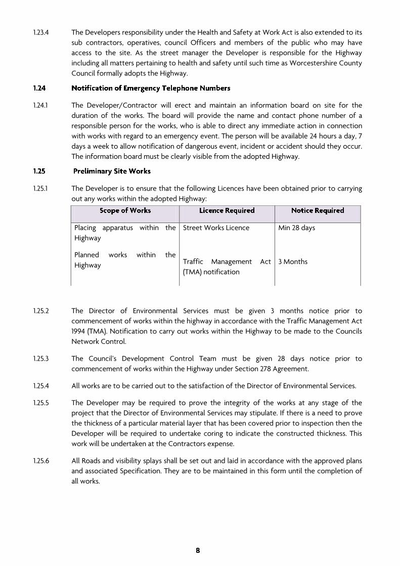
1.25.1 The Developer is to ensure that the following Licences have been obtained prior to carrying
out any works within the adopted Highway:
1.25.2 The Director of Environmental Services must be given 3 months notice prior to
commencement of works within the highway in accordance with the Traffic Management Act
1994 (TMA). Notification to carry out works within the Highway to be made to the Councils
Network Control.
1.25.3 The Council’s Development Control Team must be given 28 days notice prior to
commencement of works within the Highway under Section 278 Agreement.
1.25.4 All works are to be carried out to the satisfaction of the Director of Environmental Services.
1.25.5 The Developer may be required to prove the integrity of the works at any stage of the
project that the Director of Environmental Services may stipulate. If there is a need to prove
the thickness of a particular material layer that has been covered prior to inspection then the
Developer will be required to undertake coring to indicate the constructed thickness. This
work will be undertaken at the Contractors expense.
1.25.6 All Roads and visibility splays shall be set out and laid in accordance with the approved plans
and associated Specification. They are to be maintained in this form until the completion of
all works.
Placing apparatus within the
Highway
Planned works within the
Highway
Street Works Licence
Traffic Management Act
(TMA) notification
Min 28 days
3 Months

1.25.7 At the location(s) where the new development Highway joins the existing Adopted Highway,
the new junction bellmouth, visibility splays and footways are to be constructed to finished
surfacing levels prior to any other works commencing on site. Resurfacing/construction of
the existing footway(s)/carriageway(s) are to be extended to include any reinstatements or
service trenches connected with the new Development. Reinstatement edges are to be cut
back to a clean vertical edge and the development constructed up to that point. The
surfacing course shall be overlapped by 300mm with the vertical joint receiving hot applied
50 pen bitumen.
1.25.8 No storage of materials will be allowed on the Adopted Highway and all visibility splays are
to be maintained during the construction works.
1.26.1 The Developer and his sub contractors shall take full responsibility for the stability and safety
of all site operations and methods of construction from commencement through to final
adoption.
1.26.2 The Developer/Contractor shall adhere to the provisions of all general or local Act of
Parliament and the regulations and bylaws of any local or statutory authority during the
construction of the development.
1.26.3 The Developer shall employ a competent and experienced supervisor on site at all times. The
supervisor and at least one operative working in the Highway shall be NRSWA accredited.
1.26.4 Sub contractors engaged on the development will also be covered under the above Clause.
1.27.1 All materials used in or upon the works are to be in accordance with the appropriate British
Standard Specification and Volume 1 of the Highways Agency’s Manual of Contract
Documents for Highway Works. All materials shall be kitemarked or produced within an
approved Quality Assurance Scheme. All materials used within 450mm of finished surface
level shall be non-frost susceptible as defined in Clause 602.19 of Highways Agency (HA)
Specification for Highway Works.
1.27.2 Kerbs shall be installed prior to the construction of base layers.
1.27.3 Gully and Manhole covers within the Highway including footway ironwork shall not be set to
their final level until the completion of the installation of all base course materials.
1.27.4 Any exposed bituminous layer must be protected and kept clean for as long as it remains
exposed prior to the construction of the next layer. Where layers have become
contaminated the area is to be cleaned to the satisfaction of the Director of Environmental
Services and, before the next layer is placed the area is to receive a tack coat laid in
accordance with the requirements of Clause 920 Ss 7 of Volume 1 Manual of Contract
Documents for Highway Works. If the layer is damaged it shall be removed and replaced with
material of suitable specification.

1.27.5 All road, footway and cycleway bituminous materials shall be machine laid unless the Director
of Environmental Services has approved hand laying methods. The carriageway shall be laid in
two passes with the joint being at the centre line of the carriageway. The laying of
bituminous materials will not be allowed until all service installation has been completed.
1.27.6 All block work shall be protected from site traffic during the execution of the works. Any
damage is to be made good to the satisfaction of the Director of Environmental Services at
the Developers expense.
1.27.7 All highway verges are to be a minimum of 0.5m wide and are to be laid as grassed areas in
accordance with Section 17.
1.27.8 A sustainable approach to highway construction with particular emphasis on the use of
recycled material is encouraged. Testing for material in recycled coarse aggregate and
recycled concrete aggregate is to be undertaken in accordance with Clause 710 of Volume 1
Manual of Contract Documents for Highway Works. Worcestershire County Council has a
committed approach to the use of recycled materials and can provide an approval process
including technical assessment and laboratory appraisals as necessary. It may be possible to
use recycled materials within appropriate construction phases provided that they do not
affect the structural or performance characteristics of the development. The approval
process will be undertaken at the expense of the Developer.
1.27.9 It is recommended that the Developer and his sub contractors produce and maintain a waste
register. The waste register will detail all surplus materials that are disposed of from site. This
will allow an analysis to be performed indicating total wastage, hence lost revenue from the
project. It will therefore be possible for the Developer to formulate and administer
procedures in order to minimise the amount of wastage from site, which in turn will assist in
maximizing profitability as well as helping to safeguard the environment.
1.28.1 The surface regularity of the completed surfaces of estate road carriageways shall comply
with the following table:
+/- 6mm
+/- 6mm
+/- 15mm
+10mm/-30mm
Max 2mm difference in level between adjacent
Blocks and max 6mm under a 3m straight edge
Max 3mm under a 1m straight edge
1.28.2 Additionally, for estate roads exceeding 40m in length and for associated cycleways,
footways, footpaths and shared surfaces without drop kerbs the following table will also
apply:

10 1 Nil
18 2 Nil
1.28.3 Trenches cut through any carriageway must be reinstated such that the finished wearing
course profile is level with the immediately adjacent surface.
1.28.4 The Developer shall set all fixed surface features, boxes and ironwork in footway, cycleway or
carriageway to coincide with the level of the immediately adjacent surface. This work must
be undertaken prior to the application of the wearing course.
1.28.5 The difference in level of a fixed surface feature and the adjacent surface shall not exceed a
tolerance of +/-6mm except for those contained in the following Table:
125mm +/-5mm
25mm +/-3mm
3mm to flush +/-3mm
+5mm to +10mm
1.28.6 Where kerbs are required to be flush with the carriageway the tolerance shall be +/-3mm.
1.28.7 For a diagrammatic detail of the stepped construction detail refer to Appendix E.
1.29.1 All materials incorporated into the works shall comply with the relevant current British
Standards and/or the current edition of the Department of the Environment and the
Highway Agency Specification for Highway Works (SHW) in the Manual of Contract
Documents. This requirement also applies to installation and workmanship. The materials shall
be approved by the Director of Environmental Services and due access shall be allowed to
the Director of Environmental Services for the purpose of sampling and testing.
1.29.2 Definitions of Earthworks materials along with the requirements of compaction of
earthworks, sub base and trench reinstatements are contained within Appendix C1, C2, C3, C4
and C5 (Refer to the Specification for Highway works for compaction requirements)

1.29.3 Details of suitable compaction plant are provided within section C3, C4 and C5 and
compaction Tables for materials are provided as follows:
Appendix C3
Appendix C4
Appendix C5
(Refer to the Specification for Highway Works)
1.30.1 All materials shall comply with the SHW Clause 1704 and BS8500.
2.1.1 Turf, topsoil and other organic and unsuitable materials shall be stripped from all areas
beneath proposed carriageways, cycleways, footways and embankments to a minimum depth
of 150mm or as directed.
2.1.2 Topsoil shall be suitably stockpiled to a maximum depth of 2m and protected to prevent
rainfall scour and loss due to wind. The stockpiles should be stored separately from other
materials to avoid cross contamination.
2.1.3 No material shall be deposited within 5m of any trees or as directed should a tree
preservation order be in place.
2.2.1 The proposed area shall be excavated to a depth of 150mm or as directed. Unsuitable
material is to be removed and be replaced with approved granular material as described
within Section 2.
2.3.1 Areas below formation following the removal of turf etc are to be made up with approved
suitable fill as detailed within Appendix C1.
2.3.2 Approved granular fill shall be used to fill any ditches or similar that run beneath the line of
the proposed works. The line of ditch should be piped if it is necessary to maintain flow along
this drainage path. If this is the case, the Developer should liaise with Worcestershire County
Council or the Environment Agency.
2.3.3 Approved granular material should also be used to fill isolated deep pockets such as old
basement voids. Any vertical walls shall be broken out to below formation level and the
granular material placed and compacted within the void to the requirements of C1, C2, C3, C4
and C5.
2.4.1 Material used to make up levels to formation shall be placed and compacted in accordance
with the requirements of Appendix C1, C2, C3, C4 & C5
2.4.2 Material used to form embankments shall be to the requirements of appendix C1.
2.4.3 Any widening works to carriageways on embankments must be undertaken with approved
granular material to the requirements of Appendix C1. The material shall be benched in and
compacted in accordance with Appendix C3.

2.5.1 Suitably approved granular material shall include the following characteristics:
Characteristic Acceptance Criteria
10% Fines Value 40Kn soaked basis (BS812)
Grading Well graded 9% passing 63 m sieve
Maximum Particle Size 63mm
2.5.2 Additionally, the material must be free of clay and other contaminants. Alternatively, HER
Type 1 or Type 2 Granular sub base may be used.
2.5.3 If a granular material other than that specified within S1.5.1 has been placed as fill and exhibits
a deficiency in fines including an open textured compacted surface then the following action
should be taken:
2.5.4 Spread a fine granular material over the surface and vibro rolled in to fill all prevalent voids
prior to the placement of sub base.
2.5.5 If this is not satisfactory a separating membrane shall be installed prior to the placement of
the sub base.
2.6.1 Trench reinstatements on site should be undertaken in accordance with this Specification.
2.6.2 Trench reinstatements in the existing Highway are to be undertaken in accordance with the
requirements of ‘NRSWA Specification for the Reinstatement of Openings in Highways’.

3.1.1 Working in wet conditions will adversely affect and damage existing ground including the Sub
base and sub grade. If these materials have deteriorated due to trafficking then the material
shall be removed and replaced with Type 1 material or material corresponding to Section 2.
3.1.2 No material in a frozen condition may be incorporated into the works.
3.2.1 No material shall be laid on any surface that is frozen or covered with ice or snow.
3.2.2 Materials incorporating bitumen binders shall not be laid where the temperature of the
surface to be covered is below 2°C. If the surface is dry and free of ice or snow then laying
may proceed where the air temperature in the shade is at or above -1°C provided the
temperature is rising.
3.2.3 Footway and cycleway surface courses cannot be laid in cold, windy or wet conditions unless
precautions can be taken to ensure that the material is compacted above its minimum laying
temperature.
3.2.4 The Developer is to consider the adverse affects of applying coated chippings to rolled
asphalt materials in cold weather conditions. Wind chill factors can rapidly reduce the
temperature of the laid material and the Developers attention is drawn to the minimum
rolling temperatures contained within Appendix D.
3.2.5 Materials containing cement shall not be laid when the descending air temperature in the
shade falls below 3°C and laying shall not be resumed until the air temperature reaches 3°C.
3.2.6 Where fresh concrete or mortar containing Portland Cement has been placed within the
works and the temperature is expected to fall below 0°C within a period of up to 48 hours
after placing, then suitable insulating blankets should be used to ensure that the materials do
not freeze. These blankets must remain in place until the air temperature is at 3°C and rising.
The Developer must be made aware that the incorporation of additives or cement
replacements may retard the early strength gain. Care should therefore be taken to ensure
that damage does not occur after the initial 48-hour period.


4.1.1 Following reinstatement of any defective areas the formation shall be cleaned of any mud
and slurry prior to being compacted with a roller of suitable weight and type. The resulting
profile shall be properly shaped to an even and uniform surface in accordance with the
design levels.
4.1.2 At this stage the Developer shall obtain the approval of the Director of Environmental
Services before further works can proceed.
4.1.3 Any depressions that occur during compaction shall be filled with an approved material and
compacted to the required standards.
4.2.1 The formation shall be adequately protected from the weather and shall not be used by
construction traffic. The area should be covered with sub base as soon as is practicable.
4.3.1 If the CBR value of the formation is <5% or the formation is formed within a cohesive
material a separating membrane with the properties indicated below will be laid on the
prepared formation.
4.3.2 The separating membrane shall extend 300mm outside the kerb line and comply with the
following:
4.3.3 In accordance with SHW Specification
4.3.4 The minimum tensile strength in each direction shall be 6kN/m
4.4.1 Shared Surface, Access Roads and Industrial Estate Roads must comply with the above
requirements over their entire width.
4.5.1 Adequate drainage shall be provided on all sites to ensure that the water level is maintained
at a depth of at least 300mm below formation.
The subgrade drain pipes must be run to an approved outfall.
Subgrade drainage may not be required where the formation is not rutted and there
is no evidence of free standing water, and
Where a site investigation has deemed that the highest annual ground water level is
300mm or greater below formation
Free draining sand and gravel strata are prevalent at formation

4.5.2 Where Subgrade drainage has been found to be required but is impractical to achieve
separating membranes shall be placed above and below an additional 150mm layer Of Type 1
sub base which is to be installed below and extra to the depth required by the Plasticity
Index.

5.1.1 Refer to appendix A1 for design depths for construction. Sub base material is to be spread
evenly on the formation in layers not exceeding 150mm thick. The material is to be
compacted in accordance with the requirements of Appendix C1, C2, C3, C4 and C5. The
moisture content of the material is to be within the range optimum –2% or +1% and must not
be segregated.
5.1.2 The full thickness of the sub base should be continued to 300mm beyond the back of kerb.
5.2.1 Capping layers shall be provided to the thickness shown within Appendix A1 unless otherwise
directed by the Director of Environmental Services. Where insitu tests show CBR values less
than those predicted at design stage either the whole area of capping shall be increased in
thickness or localised soft areas shall be excavated and replaced with a new layer of capping
material.
5.2.2 The sub formation shall have the same longitudinal gradient, cross fall and surface level
tolerance as the formation.
5.2.3 Any damage to sub formation or capping by the use of construction traffic, or otherwise shall
be made good to the satisfaction of the Director of Environmental Services.
5.3.1 Capping material shall comply with the requirements set out in DoT Specification for
Highway Works, Clause 613, Class 6F1 or 6F2. The minimum Ten Per Cent fines Value for 6F2
shall be 50kN.
5.4.1 Desirable Grading Envelope for Sub Base Materials:
63mm 100
31.5mm 74 – 100
16mm 44 – 80
8mm 30 – 65
4mm 18 – 42
2mm 13 – 35
1mm 8 – 28
0.250mm 0 – 18
0.063mm 0 – 9

5.4.2 The material shall be sourced from an approved supplier and shall be crushed rock, slag,
crushed concrete or other approved materials. The material shall be well graded and must lie
within the above grading envelope limits.
5.4.3 Notes for the table above:
The particle size is to be determined by the washing and sieving method of BS EN 933: Part 1: 1997
The material passing the 425μm BS sieve when tested in accordance with BS 1377 shall be non plastic
10% fines value must exceed 40kN tested on a soaked basis in accordance with BS812.
5.4.4 Alternatively, Type 1 sub base conforming to SHW Clause 803 may be used. The material is to
fully comply with the requirement of SHW clause 803 granular material Type 1 sub base.

6.1.1 Concrete shall be either site batched or ready mixed, and shall comply with the requirements
of The DoT SHW, Clause 1704 and BS8500.
6.2.1 Aggregates shall comply with DoT SHW, Clause 1702.
6.3.1 Fine and coarse aggregates shall be separately stored on a free draining hard standing or
similar clean foundation, kept clean and free from all impurities and foreign substances, and
protected from frost.
6.4.1 Cement shall comply with BS EN 197 Portland cements or BS4027 Sulphate resisting Portland
cement. Ordinary Portland cement shall be used unless otherwise directed by the Director of
Environmental Services.
6.5.1 Approved rapid hardening cement may be used in lieu of Ordinary Portland cement only with
the prior approval of the Director of Environmental Services. All special conditions stipulated
by the manufacturer of the brand concerned as to its use shall be strictly observed.
6.6.1 Sand shall be clean washed, sharp, pit or river sand free from clay, organic matter etc and
comply with BS EN 12620.
6.7.1 The Contractor shall be responsible for making his own arrangements with the Water
Company for obtaining mains water and he shall comply with all local conditions regarding its
use.
6.7.2 If water for the works is not available from a Public Utility Undertaking Supply, the approval
of the Director of Environmental Services shall be obtained regarding the source of supply
and manner of its use. If so required, the Contractor shall arrange for tests of the water to be
carried out in accordance with BS EN 1008 and it shall only be used if the test results are
satisfactory.
6.8.1 Cement grout for general use shall be used within one hour of mixing and shall consist of
Ordinary Portland or Sulphate Resisting Portland Cement and water mixed in the proportions
necessary to ensure that the mix has adequate workability and a suitable consistency for the
intended use. Unless as the result of grouting trials or where otherwise directed by the
Director of Environmental Services, the maximum water cement ratio for any grout for
general use shall be 0.5.


7.1.1 Refer to appendix A1 for general material Specification requirements and layer thicknesses.
7.1.2 Bituminous materials shall be machine laid with the exception of small areas with prior
approval of the Director of Environmental Services.
7.1.3 Where damage occurs to the previously laid bituminous materials then the area shall be
rectified to the satisfaction of the Director of Environmental Services prior to being overlain.
7.1.4 Guidelines for delivery and rolling temperatures are given in Appendix D.
7.1.5 All vertical faces of ironwork within the wearing course depth are to be coated with cold
applied or hot bitumen immediately prior to the laying of the wearing course.
7.2.1 The base layer(s) material shall be Dense Bitumen Macadam to S8.3.1 below. The materials
formulation and compaction standards shall be such to ensure that insitu air voids are more
than 2% but less than 10%. For compliance, all DBM materials shall conform to the
requirements of the
7.2.2 Specification for Highway Works Clause 929.
7.3.1 The material shall be 0/32mm DBM 125Pen Base to BS4987. It shall be placed in 2 layers of
equal thickness and thoroughly compacted in accordance with BS4987, Part 2. Binder to be
either 100 -150 pen or alternative approved.
7.4.1 The material shall be 0/20mm DBM 125PEN Binder Course to BS4987. It shall be compacted to
the same standards as for Base Layer. Binder to be either 100 -150 pen or alternative
approved.
7.5.1 The material shall be High Stone Content Asphalt 55% 14mm conforming to the requirements
of BS594 Type C.
7.6.1 Block paving in the form of precast concrete rectangular blocks of dimensions 200 x 100 x
80mm laid on a laying course in accordance with S8.6.3 below.
7.6.2 Blocks shall comply with BS 6717, Part 1, 2001 (to Type R requirements) and the permitted
colours are to be determined by the Director of Environmental Services.
7.6.3 Blocks shall be laid on a 30mm compacted thickness of category 11 laying course (sharp) sand
in accordance with the requirements of BS 7533 Pt3, 1997. The method detailed in 4.3.3.a, of
that document shall be adopted for installing the laying course.

7.6.4 Surface regularity for Blockwork is defined in Section 1.29.
7.6.5 Gaps between kerb face and blocks and between ironwork and blocks must be kept to a
minimum and sealed with a well rammed mixture of 3:1 dry clean sharp sand to O.P.C cement
or proprietary sealing system.
7.6.6 All block paving shall be sealed on completion with a proprietary sand stabilisation material.
8.1.1 All kerb and channel Races are to be installed prior to the laying of the base course material.
8.1.2 Kerb Races shall be constructed using ST4 concrete to SHW Clause 2602 not less than 150mm
thick and 375mm wide at the profile shown in Appendix E. The kerbs shall be backed with ST4
concrete. Width of kerb foundation to be increased by 150mm on kerb radii of 50 metres or
less.
8.2.1 Kerbs shall be laid to general regularity and with upstands indicated on the drawings
contained within the Appendix drawings and in the requirements of BS7533. Current concerns
regarding manual handling of precast concrete units shall be taken into account during the
design and construction phases of the Development.
8.2.2 Where an asphalt surface course is employed, precast concrete kerbs shall be used. Such
kerbs shall be 125mm x 255mm hydraulically pressed, Type HB2, half batter to BS 7263-3 and
laid upright. Kerbs are to be bedded in mortar within 25mm of the face of the concrete
beam, laid with dry joints and backed with ST4 concrete extending over full width of kerb
foundation, to within 50mm of the top of the kerb.
8.2.3 No cut kerb shall be less than 500mm in length.
8.3.1 For curves of radius 12.5m or tighter, the appropriate radius kerb shall be used.
8.3.2 For curves of radius 50m or less, width of kerb foundation to be increased by 150mm.
8.4.1 Blockwork kerbs are to be in accordance with the details indicated within the standard
drawing appendix, bedded on grade ST4 Concrete with a 25mm mortar bed.


9.1.1 Type D400 double triangular Gully gratings and frames shall be kite marked to BS EN 124:1994.
Either cast steel of Ductile Iron may be used. The frames shall be bedded on a gauged Class 1
(3:1) sand/cement mortar and at least 2 courses (max 3 course) of Engineering Brickwork Class
‘B’ to BS3921: 1985. (Refer to standard detail in Appendix E).
9.1.2 Gully Frames to be 150mm depth on 'A' and 'B' class roads and Industrial estate roads. All
other roads to have 100mm depth frames unless otherwise directed by the Director of
Environmental Services.
9.2.1 Gully spacing is to be determined from the requirements of HA 102/00, Design Manual for
Roads and Bridges.
9.3.1 All road gully gratings situated within cycleways, footways, shared surfaces etc shall be of a
suitable Type approved by the Director of Environmental Services.


10.1.1 Gully pots used for carriageway gullies shall generally be of precast concrete using Sulphate
Resisting Cement (SRC) in accordance with BS 5911, part 230, 1994.
10.1.2 Gully pots shall have internal dimensions 450mm diameter by 900mm deep and shall be of
the trapped type unless otherwise directed by the Director of Environmental Services.
10.1.3 PVCu plastic gully pots (BBA Approved) of the above dimensions may be used at the
discretion of the Director of Environmental Services. The typical detail of this type of gully
installation shall incorporate suitable provisions to prevent the pots floating and distorting
when the concrete surround is placed and compacted. The installation shall be entirely in
accordance with the BBA approval certificate requirements. The Director of Environmental
Services would expect the BBA requirement to at least be equivalent to a concrete base slab
provided below the pot bed and surround and which may take the form of a paving slab set
on 100mm of ST2 concrete to SHW Clause 2602.
10.2.1 Concrete gully pots shall be installed in accordance with BBA approval requirements. The
pots are to be set on and surrounded by 150mm of ST2 concrete sulphate resistant cement to
SHW clause 2602.
10.2.2 PVCu plastic pots shall be set on and surrounded by ST2 concrete. The surround shall be
200mm thick with a 100mm bed above the base slab in S11.1.3.


11.1.1 It is usual that the Local Water Company under a section 104 agreement will adopt new
drainage systems. Worcestershire Council will adopt the gullies and connections only in these
circumstances subject to satisfactory installation.
11.1.2 Where no public stormwater sewer is proposed, an adequate piped highway surface water
drainage system of approved pipe sizes; gradients and materials shall be provided to an
outfall.
11.1.3 Highway surface water drains shall be laid in straight lines at uniform gradients between
manholes. Sight rails shall be erected at intervals of no more than 45m and at changes of
gradient.
11.1.4 Where an outfall drain or pipe unavoidably passes under land which will ultimately be
conveyed to a dwelling, or which will ultimately remain undedicated as Highway, an Easement
will be required giving the Highway Authority right of access at all times for the purpose of
maintenance or repair. Acknowledgement of the presence of such a drain under each
affected property must be safeguarded by the incorporation of a suitable Easement within
the conveyance of that property by the Developer.
11.1.5 Where an outfall, drain ditch or pipe will discharge into an existing drain or pipe or
watercourse not maintainable by the Local highway Authority, written evidence of the
consent of the authority or owner responsible for the existing drain etc to such discharge
shall be provided to the Director of Environmental Services.
11.1.6 No highway surface water outfall drain shall pass below any building.
11.1.7 Backfilling of pipe runs must be in accordance with Section 3.
11.2.1 The following types of pipe may be used for surface highway drains:
Concrete pipes made
PVCu twin walled with a smooth internal and ribbed external surface walls with current BBA certification.
Vitrified Clayware pipes to BS EN 295-1:1991
11.2.2 Jointing and installation shall be undertaken to Manufacturers Specification.
11.3.1 All drainage runs irrespective of depth shall have a bed and surround of 150mm of concrete
grade ST4 WITH sulphate Resistant Cement to SHW clause 2602.
11.3.2 In the case of plastic pipes care should be taken to ensure that the pipes do not float when
the concrete is placed.

11.3.3 To maintain a degree of flexibility 13mm fibreboard (flexcel) or otherwise approved shall be
placed at the pipe joints to the full width of the concrete surround.
11.3.4 For porous pipes the surround shall comprise of at least 150mm of no fines concrete to SHW
Clause 2603.
11.4.1 Soakaways will not be allowed on new Developments unless all other courses of action have
been eliminated. The Director of Environmental Services must approve their use prior to their
inclusion within the Development. (Refer to Standard Detail in Appendix E).
11.5.1 On the completion of the works and also prior to adoption, all drains, manholes, gullies etc.,
shall be cleaned out, flushed, and left free from all obstructions to the satisfaction of the
Director of Environmental Services. Power cleaning may be required.

12.1.1 All manhole covers and frames intended to be used within the Highway shall be kite marked
products to BS EN 124, 1994 and badged S.W. (Surface Water) and F.W. (Foul Water)
12.1.2 The following additional requirements are to be met:
In carriageways and trafficked footways/Cycleways - Heavy Duty: BS EN 124 reference D400 with a clear opening of 600mm and minimum frame and cover depth of 150mm.
In footways/Cycleways and verges – Medium Duty: BS EN 124 reference C250 with a clear opening of 400mm.
12.2.1 The frames shall be bedded on a gauged Class1 sand/cement mortar to Clause 2404 and BS
5628 Part 3:2001 above two to three courses of Engineering Brickwork Class B to BS3921: 1985.
12.2.2 Alternative bedding materials may be permitted but will require the approval of the Director
of Environmental Services prior to commencement.
12.3.1 Inspection chamber covers in the road can be potentially hazardous to motorcyclists and
pedal cyclists, as the skid resistance of the cast iron cover can be less than the surrounding
road surface. This can be particularly hazardous on bends and at junctions in wet conditions.
Covers also become polished over time and this reduces the grip further.
12.3.2 During the design process for Section 278 and 38 schemes the Designer should consider the
potential risk for cyclists and motorcyclists at locations such as roundabouts, traffic signal
junctions, pedestrian crossings, bends, gradients, and all areas of high friction surfacing within
the existing highway and new roads. When the provision of chambers cannot be avoided at
such locations the use of anti-slip chamber covers with a minimum PSRV (polished skid
resistance value) of 65 should be considered in critical braking areas and where vehicles
change direction, i.e. junctions and bends. The use of anti-slip chamber covers should be
agreed at specific locations with the Councils Engineer during the scheme design process.
12.3.3 In addition to the anti-slip requirements chamber covers should comply fully with the
standards specified in BS EN124 as detailed above.
12.3.4 Worcestershire County Council is only responsible for the maintenance of surface water
manhole covers forming part of highway drainage systems. All other inspection chamber
covers located within the highway are the responsibility of private utility companies such as
electricity, telecom and water suppliers. The Developer must seek the approval of the
relevant Statutory Undertaker to use anti-slip chamber covers at specific locations and
provide evidence of approvals obtained to the Councils Engineer.


13.1.1 All pipe inlets or outlets to or from open watercourses must be provided with a headwall
incorporating any necessary apron, scour baffle, handrails or other works. Suitable designs
must be submitted to the Director of Environmental Services for approval, This may require
also require structural approval process. A suitable Design is included within Appendix E.
13.1.2 In certain locations, and with the approval of the Environment Agency, flap valves may be
required. Flap valves should be made of heavy duty plastic (low maintenance type) or other
approved by the Director of Environmental Services.
13.1.3 The invert level of the outlet pipe through the headwall shall be subject to scrutiny and
approval by the Director of Environmental Services to ensure satisfactory flow through the
drainage system.
13.1.4 Where headwalls are located within 6m of the footway, cycleway or carriageway they shall
be provided with pedestrian safety railings to the requirements of the Director of
Environmental Services.


14.1.1 The formation of the footway/footpath/Cycleway shall be levelled and compacted with a
vibrating roller or other approved suitable item of plant to a properly shaped, even and
uniform surface. Reference should be made to Appendix C1, C2, C3, C4 and C5, Compaction
plant.
14.1.2 The formation shall be treated with an approved weed killer before construction
commences. Only trained and certificated operatives will be permitted to use weed killers.
14.1.3 Bituminous materials shall be machine laid; where the Director of Environmental Services has
given his approval small areas may be permitted to be hand laid.
14.2.1 The material used shall be granular sub base material Type 1 SHW clause 803. The thickness
shall be 150mm.
14.3.1 The Footway/Footpath binder course shall be 75mm compacted thickness bitumen Macadam
0/20mm DBM 125Pen Binder Course to BS4987.
14.4.1 The Footway/footpath surface course shall be 25mm compacted thickness bitumen
Macadam 0/6mm BDM 190Pen SC L/Stone to BS4987 with bituminous grit brushed in.
14.4.2 An examination of the surface course will be undertaken prior to adoption to ascertain
prevalent defects. Any defects are to be rectified at the Developers expense.
14.4.3 Guidelines for delivery and rolling temperatures are given within Appendix D.
14.5.1 The final footway surface shall have a Crossfall of 1:40 towards the carriageway.
14.6.1 Where a footway does not abut a kerb or boundary wall a 50mm x 150mm hydraulically
pressed, precast, flat topped or bull nosed (as directed by Director of Environmental Services
representative) concrete edging to BS 7263, Part 3:2001 Type EF, figure K3 b shall be provided.
14.6.2 The precast edging must be securely bedded on a foundation of ST4 concrete SHW Clause
2602 - a minimum of 200mm deep and 200mm wide. It shall be backed with ST4 concrete
from the back of the bedding to within 50mm (minimum 40mm) from the top of the edging.


15.1.1 Vehicular crossings are to be provided at the entrances to all garages and residential
properties with sufficient width to accommodate a vehicle.
15.1.2 For a single use vehicular crossing a minimum of three precast concrete kerbs 125mm x
150mm to BS 7263 Part 1 1994 Type BN, in accordance with drawing 008 shall be installed to
provide a vehicular crossing with a minimum width of 3.6m. For multiple use vehicular
crossings a 125mm x 255mm type BN kerb shall be used. These dropped kerbs shall be set to
show an upstand of 25mm with tolerances as given in Section 1.29.
15.2.1 Where pedestrian routes cross carriageways and footways at junctions, two dropped kerbs
with tapers shall be provided on each side of the carriageway or junction. Tactile paving shall
be installed in accordance with the Drawing Appendix and at the approval of the Director of
Environmental Services.
15.2.2 The dropped kerb shall be set +6mm to flush with the carriageway channel level to the
tolerances given in Section 1.29.
15.3.1 Where a cycleway adjacent to the carriageway is interrupted by pedestrian or vehicular
crossings, the change in level shall be achieved over at least two kerbs, using standard precast
concrete kerbs and laid to suit in place of the standard one taper kerb.
15.3.2 The dropped kerb shall be set +6mm to flush with the carriageway channel level to the
tolerances given in Section 1.29.
15.4.1 Singular residential vehicular crossings shall be constructed in accordance with the details
indicated within the Standard Drawings (Appendix E).
15.4.2 For multiple residential crossings and commercial and industrial crossings the construction
shall be as per Standard Road Specification.
15.5.1 Dropped kerbs and tapers shall comply with the requirements of BS 7263, Part 1, 1994 figures
2(a) and 2(k) respectively.
15.5.2 Kerbs shall be laid to a flowing alignment and to the construction requirements of Section 10
of this Specification.


16.1.1 The Developer shall carry out all work in the Specification in accordance with BS 7370
General Landscape Operation or a Standard approved by the Director of Environmental
Services.
16.2.1 The topsoil shall be cultivated to a depth of 125mm avoiding the disturbance of the subsoil,
by suitable approved mechanical means or by hand cultivation on banks or confined areas. All
stones over 25mm in any dimension, weeds, roots and other undesirable material shall be
removed from the location and disposed of at an approved Refuse Disposal Site. Soil shall be
brought to a friable tilth by treading, firming and raking. Where applicable the degree of
accuracy in determining a level profile shall be determined by boning rods, or other approved
means, after firming in accordance with BS 7370. Operations shall not be carried out during
periods of inclement weather where the ground is saturated, boggy or frost covered.
16.3.1 After final grading all areas to be seeded or turfed shall have a base dressing of an approved
granular pre-seeding fertilizer applied at the rate of 50g per sq.m. The dressing shall be
applied by means of approved fertilizer distributor machinery or by hand in small confined
areas and then lightly worked into the surface with harrow or rake. The final level for seeding
shall be 50mm above any adjacent hard surface area and shall be flush with any adjacent hard
surface for turfing.
16.4.1 After cultivation operations have been carried out, the areas shall be sown with grass seed,
which has been stored off the ground in a clean, dry place free from vermin. The Developer
shall be required to supply Certificates for all grass seed stating the source, mixture,
percentage purity and percentage germination rate and date of purchase. The Director of
Environmental Services will be entitled to take samples of the grass seed mixture for testing.
The seed mixture shall meet the requirements of germination and purity laid down in BS 7370.
Following an even distribution of seed, the developer shall carry out a light raking or
harrowing of the area and ensure consolidation of the seed with the soil by the use of a light
roller. All reasonable precautions shall be taken to ensure that pedestrians and other traffic
does not cross areas during cultivation or until the grass is established.

16.5.1 After cultivating operations have been carried out, the areas shall be laid to turf, a sample of
which has previously been approved by the Director of Environmental Services. Turf shall be
to a uniform size and thickness from an approved supplier. It shall be laid with the use of
boards in order that the Developer does not allow the previously laid grass to be walked on.
All turf laid down shall be firmed with a wooden turfing hammer to give a uniform even area
finishing 25mm above the edge of any adjacent hard area. Turf shall be laid in broken joints in
a half band pattern. All turf shall be laid within 24 hours of delivery from the supplier and shall
not be damaged or yellowed. Following turf laying an approved top dressing shall be spread
and brushed over the turfed area ensuring all joints are adequately filled. To prevent
scorching and shrinkage the turf shall not be allowed to dry out during establishment.
16.6.1 During the Spring following seeding, and before the application of any selective Weedkiller,
the grassed area shall be dressed with an approved granular post seeding fertilizer applied at
the rate of 50g per sq.m. During the period of establishment, all newly grassed areas shall be
cut twice, each cut reducing the growth height by one third. The first and second cuts shall
take place when the growth height reaches 75mm. Seeded areas shall be lightly rolled to
consolidate the surface one week prior to the first cut. Cutting is to take place using suitable
mowing machinery when conditions are not excessively wet or damp. Cutting shall be
continued at appropriate intervals until the finished maximum height is 25mm.
16.7.1 During the Spring following seeding, and before the application of any selective Weedkiller,
the grassed area shall be dressed with an approved granular postseeding fertilizer applied at
the rate of 50g per sq.m. During the period of establishment, all newly grassed areas shall be
cut twice, each cut reducing the growth height by one third. The first and second cuts shall
take place when the growth height reaches 75mm. Cutting is to take place using suitable
mowing machinery when conditions are not excessively wet or damp. Cutting shall be
continued at appropriate intervals until the finished maximum height is 25mm. During the
period of establishment the Developer shall water the turf as often as necessary to ensure it
does not dry out prior to establishment.
16.8.1 When instructed by the Director of Environmental Services, the Developer shall overseed
sparse or thin areas of turf. The turf shall be overseeded using suitable and appropriate
cultivers of grass seed approved by the Director of Environmental Services at the rate of 35g
per sq.m. The surface shall be graded or topsoiled as necessary to provide even running levels
and a surface suitable for seeding.
16.9.1 Edge support delineation through vehicular, pedestrian crossing points and around street
lighting columns shall be provided by the installation of 50mm x 150mm Hydraulically-
pressed, precast, flat topped, concrete edgings to BS 7263, Part 3:2001 Type EF, Figure K3b.

17.1.1 All highway lighting, illuminated signs and illuminated bollards must be designed, specified
and installed to Worcestershire County Council (WCC) requirements.
17.1.2 There are 2 methods for developers to achieve the above requirements:
Developer elects to use the design facilities of Wor cestershire County Council and its partnering consultant Halcrow. Lighting will be designed
to WCC requirements for an agreed fee.
Developer elects to design the highway lighting scheme in house or by using a specialist highway lighting Consultant. In either instance, designers
must comply with the competency requirements specified by WCC.
The design must be submitted to WCC for approval. A fee will be charged for
checking all designs submitted by the Developer. If the first submission is found
to be unacceptable, an escalating fee will be charged for subsequent
submissions.
The design must be approved prior to any installation work commencing on site
Full details of the above methods are contained in the following sections.
17.1.3 If a developer fails to follow the requirements of either of the above methods, the highway
lighting will not be adopted.
17.1.4 Method 1 is recommended as the preferred approach to fulfil WCC requirements as it
provides a streamlined approach and reduces the developers’ risk.

WCC to design Developer to design
-
Developer to set out column
positions
- WCC design check
Installation of approved scheme - Redesign - additional design
checks
++
Supplying WCC with Test documents - Developer to set out
column positions
-
Inspection of approved scheme - Installation of approved
scheme
-
Additional installation inspections ++ WCC to inspect installation -
Bulk clean and lamp change Additional installation
inspections
++
Light level checks Bulk clean and lamp change
Payment of any Commuted Sums Light level checks
Adoption - Payment of any Commuted
Sums
Adoption -
++ = Escalating charges
17.3.1 Developer elects to use the design facilities of Worcestershire County Council and its
partnering consultant Halcrow. Lighting will be designed to WCC requirements for an agreed
fee. If a Developer wishes to use this design service, then all drawings are to be supplied to
the WCC Street Lighting Section in AutoCAD (.dwg) format.
17.3.2 Where environmental considerations dictate e.g. Conservation Areas, it may be decided by
the County Council that enhanced choices of materials are required, reduced standards of
highway lighting could be provided or no lighting at all. In such locations the views of the
respective District, Town or Parish Council are considered. Developers must advise WCC
Street Lighting Section of any special environmental considerations that may affect lighting
provision at the time of requesting a design.
17.3.3 Where alternative or special highway lighting lanterns and columns are requested by the
Developer and are acceptable to, and approved by WCC Street Lighting section, a commuted
sum will be required to cover the future additional maintenance/replacement costs.
17.3.4 Listed Building Consent for attaching highway lighting equipment or illuminated signs to listed
buildings may be a requirement where applicable. The Developer will fund and be responsible
for the application and obtaining any such Wayleave and Listed Building Consent.
17.4.1 It will be the responsibility of the Developer (or his appointed independent Consultant or
lighting contractor) to mark out on the site, the final lighting column positions in accordance
with the approved design.
17.4.2 The Developer or his appointed independent Consultant shall deal with any
correspondence/queries that may arise either with the Developer or members of the public
etc but copies of correspondence/responses must be forwarded to the WCC Street Lighting
Section for record purposes. Column positions may not be changed without the prior
agreement of Worcestershire County Council.
17.4.3 It will be the Developer's responsibility to ensure that prospective property purchasers are
fully aware of the location of all highway lighting equipment. Any subsequent alterations to
an approved layout due to site considerations will not be approved unless the Developer can
demonstrate that this change has been brought to the attention of owners/prospective
purchasers.
17.5.1 On sites where highway lighting already exists, the Developer shall be responsible for
maintaining lighting provision (by means of temporary lighting if necessary), to the approval
of WCC Street Lighting Section. Lighting levels are to be not less than 20 Lux average and 10
Lux minimum over the whole area of carriageway affected by the works.
17.5.2 Existing highway lighting, illuminated signs or bollards shall NOT be disconnected prior to
approval from WCC Street Lighting Section. Existing lighting may be the property of a
District, Town or Parish Council; therefore early consultation is required to establish
ownership of all existing lighting.
17.5.3 Electrical services to all highway lighting are to be supplied by the Distribution Network
Operator. Generally Passive Safe equipment and signs and bollards located on islands and
roundabouts are to be supplied using private cable from a dedicated local feeder pillar, but
unless otherwise specified by Worcestershire County Council, private cables are NOT
permitted. Details of the District Network Operator or their agent for this work can be
obtained from WCC Street Lighting Section.
17.5.4 Where District Network Operator connections are required all underground electrical are to
be installed in ducting as specified by the Distribution Network Operator.
17.5.5 For all private underground services 100mm smooth bore MDPE duct (orange colour) is to be
installed to Worcestershire County Council’s requirements.
17.5.6 Where the extent of the removal is temporary to facilitate other works, the developer will be
responsible for safe storage and subsequent return in original condition and to working
operation.
17.5.7 The developer shall be responsible for the implementation of all work required in the
removal, replacement or resiting of any existing lighting equipment made necessary by the
site works. This work may involve the total removal and disposal of units from site and/or the
replacement/resiting of units within the general area affected by the site works.
17.5.8 Installation work is to be carried out by a WCC approved specialist highway lighting
Contractor. A list of specialist Approved Highway Lighting Contractors can be obtained from
WCC Street Lighting Section. All highway lighting contractors who are approved must hold
up-to-date Highway Electrical Sector Scheme certificates of competency, be Members of the
National Inspection Council of Electrical Installation Contractor (NICEIC) and the Association
of Street Lighting Contractor (ASLEC).
17.5.9 To safeguard Health and Safety, all statutory requirements and any other requirements
specified by WCC must be fully complied with. Developers should note that existing lighting
points and illuminated signs may be supplied either by private cable or DNO cable. Guidance
must be sought from Worcestershire County Council.
17.5.10 Highway lighting columns are to be sited at the rear of and within the footway and within the
adoptable area.
17.5.11 All highway lighting columns are to be numbered in accordance with the approved highway
lighting standard design drawing NWL 1 of Worcestershire County Council’s specifications
(available on request).
The Developer must arrange for the highway lighting installation Contractor to electrically
test all the highway lighting equipment, including any private cables, installed on the
development. The testing must be in accordance with the latest edition of BS7671 at the time
of the test and in accordance with the requirements of WCC Street Lighting Section
specification
17.6.2 A copy of the completed Test Certificate (ECTIC) that is issued with the design brief
must be returned within 7 (seven) days of the test readings being recorded. The ECTIC
form is available on request.
17.7.1 WCC Street Lighting Section will carry out a full inspection of the highway lighting system
upon request by the Developer prior to Adoption. Any defect noted on inspection will be
identified and referred back to the Developer or his appointed independent Consultant.
17.7.2 Any defects found and notified to the Developer or his appointed independent Consultant
must be rectified within eight weeks of the defect report being issued.
17.7.3 Special note should be made of the cost implications under Item 8 for any abortive
Inspection visits by the WCC Street Lighting Section.
17.7.4 In advance of the inspection by WCC, the Developer shall undertake lighting measurements
to demonstrate that design levels have been achieved in practice.
17.7.5 Worcestershire CC is able to offer this service for an additional fee.

17.7.6 All Wayleaves and Listed Building Consents shall be fully agreed and completed and
submitted to WCC before inspection can commence.
17.8.1 For a period of 12 (twelve) months from the date on which the Worcestershire County
Council Development Control Section certifies in writing that the works are complete, the
Developer shall execute all work necessary to maintain the highway lighting in good repair
and rectify any faults as directed by WCC Street Lighting Section. During this time the
Developer is fully responsible for all costs associated with the equipment until formal
Adoption this includes:
17.8.2 Any damage whether accidental or due to vandalism, all operational and maintenance costs
which includes:
Routine maintenance such as lantern cleaning and regular checking on continuing
operation.
Non-routine maintenance such as replacement failures of lamps, photoelectric cells,
electrical control ballasts, fuses.
Electrical energy.
17.8.3 At the time of formal adoption, a complete lamp change will be required. This will be carried
out by Worcestershire County Council’s maintenance contractor at the Developer’s expense.
17.8.4 Worcestershire County Council expects the Developer to maintain the unadopted
installation in safe working order, and repair all faults within 5 workings days from the fault
occurring.
17.9.1 A fee will be charged to undertake the Highway Lighting design. A quotation will be provided
after submission of a detailed Highways layout drawing. These charges will be subject to a
minimum charge for each Section 38 or Section 278 Agreement.
17.9.2 The Developer will be required to make a one- off payment to Worcestershire County
Council for the following: -
17.9.3 Section 38/278 Agreements; where enhanced equipment is agreed, a charge shall be made for
the additional renewal and maintenance cost as determined by WCC Street Lighting Section.
17.9.4 Section 278 Agreements; the cost of maintenance and replacement for each highway light
and illuminated sign based on a 30 (thirty) year design life period. This cost will apply to each
highway unit that is subject to the Section 278 Agreement.
17.9.5 The Developer will be required to make a payment to WCC for each requested follow-up
inspection of the highway lighting system on a development prior to Adoption, after a
previous inspection has resulted in faults being reported and then found not to have been
rectified.
17.9.6 Under Section 38 Agreements the Developer will meet the cost for cleaning and the
installation of replacement lamps in each highway light, illuminated sign and bollard (bulk
change) on completion of Adoption. This cost will apply to each highway unit that is subject
to the Section 38 Agreement.
17.9.7 The scale of charges applying at the date of enquiry for Commuted Sums and for abortive
site visits in respect of inspections by the County Council can be obtained from WCC Street
Lighting Section.
17.10.1 Developer elects to design the highway lighting scheme in house or by using a specialist
highway lighting Consultant.
17.10.2 Designers must comply with the requirements of the Institution of Lighting Engineers’
Competency Requirements for Lighting Design Staff meeting the requirements of HD46-06
and the CDM 2007 Regulations.
17.10.3 If a Developer does wish to carry out their own highway lighting design, the specification
brief for that location must be obtained from Worcestershire County Council Street Lighting
Section. The design must then be submitted and approved prior to any installation work
commencing on site.
17.11.1 The need for communication and co-ordination between Worcestershire County Council’s
Street Lighting Section and the Developer from an early stage is essential to the success of
this process.
17.11.2 Unless stated otherwise, Worcestershire County Council will require the Developer to
provide highway lighting schemes conforming to the most recent appropriate published
Codes of Practice standards for roads, footways and cycle tracks that are to be adopted as
highways maintained at the public expense.
17.11.3 All highway lighting must be adopted by the relevant Lighting Authority. The Lighting
Authority may be Worcestershire County Council or a District, Town or Parish Council. In
some instances Worcestershire County Council will act as the design/approval agent for a
District, Town or Parish Council.
Where environmental considerations dictate e.g. Conservation Areas, it may be decided by
the County Council that enhanced choices of materials are required, reduced standards of
highway lighting could be provided or no lighting at all. In such locations the views of the
respective District, Town or Parish Council are considered. Developers must advise
Worcestershire County Council Street Lighting Section of any special environmental
considerations that may affect lighting provision at the time of requesting a design brief.
17.11.4 Where alternative or special highway lighting lanterns and columns are requested by the
Developer and are acceptable to, and approved by Worcestershire County Council a
commuted sum will be required to cover the additional maintenance/replacement costs in
the future.

17.11.5 Listed Building Consent for attaching highway lighting equipment or illuminated signs to listed
buildings may be a requirement where applicable. The Developer will fund and be responsible
for the application and obtaining any such Wayleave and Listed Building Consent.
17.11.6 Where new private road or major private access junctions are created, adjustments or
additions to the highway lighting along the existing highway may be required, and either a
Section 38 or a Section 278 Agreement will be required from Worcestershire County Council
Development Control Section.
17.12.1 Highway lighting designs must achieve the required lighting levels for the appropriate
category using the minimum number of lights. Adherence must be made to the
recommendations published in the latest relevant editions of British and European Standards
for such installations and it is required that Developer’s follow guidance and advice as set out
in the UK Lighting Board’s document ‘Well-Lit Highways’.
17.12.2 The Developer shall give due consideration to the most economically effective equipment in
order to achieve the lowest whole life cost of the installation. In addition, designs shall
minimise environmental impact and energy consumption. Worcestershire County Council is
especially concerned with the ongoing reliability and future procurement of replacement
lighting equipment in order to maintain highway lighting systems effectively and have
therefore standardised on the types of equipment that are available from the specialist
manufacturers. This information will be provided with the Design Brief.
17.12.3 All highway lighting schemes whether designed by the Developer, an appointed specialist
highway lighting Consultant or by the Worcestershire County Council must meet the
following criteria:
17.12.4 Lighting schemes shall be designed in accordance with BS EN 13201:2003 and BS 5489 – 1:2004
17.12.5 The Highway Lighting Designer must consider the need or otherwise for the use of passive
safe street lighting as TA 89/08 with equipment complying with BS EN 12767: 2007.
17.12.6 Design drawings must show illuminance contours and shall be accompanied by calculations
giving the following information (all definitions and calculations are to be in accordance with
BS EN 13201:2003): -
17.12.7 The Crime and Disorder act 1998 places a duty on local Authorities and the Police to ensure
that community safety is included in all Developments and this is therefore an important
consideration in the design of the highway. In order to comply with Worcestershire County
Council’s obligations under the Act, the Developer will need to demonstrate how they have
considered the effect of the highway lighting design upon crime and disorder.
17.12.8 Worcestershire County Council is committed to the principles of ISO14001 – Good
Environmental Management. Designers must take into account the long-term environmental
impact of their proposals when developing their designs. Developers will be required to
substantiate the environmental impact of their proposals as part of the approval process.

17.12.9 Waste Electrical and Electronic Equipment Directive: Producers have responsibility for the
disposal of electrical equipment at the end of its life. Worcestershire County Council will
expect sight of the Developers’ Site Waste Management Plan.
17.12.10 Worcestershire County Council Street Lighting Section is committed to the principles for the
control of upward light contained in the Institution of Lighting Engineers (ILE) Guidance
Notes for the Reduction in Light Pollution. All developers’ designs must comply with this
document. For any development, Worcestershire County Council Street Lighting Section will
specify an environmental zone and the Developer must demonstrate compliance as part of
the approval process. Developers will also be expected to refer and adhere to relevant
sections in the Clean Neighbourhoods and Environment Act 2005.
17.12.11 As part of the design process, the Lighting Designer must undertake a detailed design risk
assessment which will include construction, maintenance and demolition issues. Evidence of
this risk assessment covering maintenance and demolition issues must be included within the
design submission for approval.
17.12.12 All lighting points, illuminated signs, bollards and any private cable must be located within the
adoptable highway boundary (that is, those areas to be adopted and maintained by the
County Council as highway as agreed by the Developer with Worcestershire County Council
Development Control Section). This must include any new additional highway lights and
feeder pillars where necessary at any existing junctions or any proposed new accesses.
17.12.13 Design drawings must show alterations/removal of any existing highway lighting columns on
site or nearby, including details of identification numbers of existing highway lighting to
remain in-situ, to be re-sited or to be removed. The submitted lighting design must blend
seamlessly with the existing installation.
17.12.14 Where there are trees or other obstructions, the spaces between adjacent highway lighting
columns may be reduced as appropriate. Similarly the requirement to illuminate traffic
calming measures is likely to reduce the spacing. Any reductions in spacing must be
supported by a technical submission including the relevant calculations.
17.12.15 Where columns are to be positioned close to trees/planting, due account must be taken of
future growth and the effect on the lighting distribution. Damage to tree roots is to be
avoided at all times and the installation is to comply with NJUG 10 (Planning, Installation and
Maintenance of Utility Services in Proximity to Trees).
17.12.16 A full specification of equipment shall be provided by the Developer, to include Appendices
13,14 and 19, and any others as applicable from the Specification for Highways Works ‘Manual
of Contract Documents for Highways Works’ published by the Highways Agency.
17.12.17 Electrical services to all highway lighting are to be supplied by the Distribution Network
Operator. Except where indicated by Worcestershire County Council, private cables are NOT
permitted. Generally Passive Safe equipment, and signs and bollards located on islands or
roundabouts are to be supplied using private cable from a dedicated local feeder pillar.
17.12.18 Failure to show such significant features on a highway lighting design drawing may result in
expensive relocation of columns at the developer’s expense before the commencement of
the maintenance period.

17.12.19 Where appropriate the fixing of highway lighting equipment on structures should be
considered and agreed by the Worcestershire County Council Street Lighting Section prior to
a design being completed. Lanterns fixed to buildings will not normally be acceptable if they
are more than 2 (two) metres from the carriageway edge or 3 (three) metres from a footway.
Particular attention should be paid to the use and routing of Mineral Insulated Cable. .
17.12.20 Generally, mounting lanterns at heights below 5 (five) metres will not be accepted except in
the case of covered passages that are to become part of the public highway. The Developer
shall submit a Departure from Standards report to include location and extent of the
departure, mitigation measures and technical justification, where previously discussed with
Worcestershire County Council. A Departure from Standards report is required even when it
states that there is no Departure from Standards.
17.12.21 For lighting installations designed to BS EN 13201:2003, ME Series. (Generally lighting columns
of 8 metre mounting height and above).
Average Luminance: The average amount of light reflected from the road surface to
an observer (measured in cd/m²).
Overall Uniformity: The ratio of minimum to the average luminance over a defined
road surface viewed from a specified observer position.
Longitudinal Uniformity: (UL) the ratio of the minimum luminance along a
longitudinal line through the observed position on the carriageway.
Threshold Increment: (TI) Classification applied to a lantern given the expected glare
from the lantern.
Surround ratio (SR) (of illumination of carriageway of a road) average illuminance on
strips just outside the edges of the carriageway in proportion to the average
illuminance on strips just inside the edges.
17.12.22 For lighting installations designed to BS EN 13201:2003, S Series. (Generally lighting columns of
5/6 metre mounting height).
Average illuminance: (Eav) the average amount of light that is falling on the road
surface (measured in Lux).
Minimum point illuminance: (Em) the minimum amount of light at any particular
point on the road surface.
For Conflict Areas designed to BS EN 13201:2003, CE Series.
(This is intended for drivers of motorized vehicles, and other road users, on conflict
areas such as shopping streets, road intersections of some complexity and
roundabouts).
Illuminance values for the whole area and its immediate approaches represented by
Iso-Lux diagrams.
The minimum maintained illuminance (E in lux) must be shown at the kerb edge of
the area.

Overall Uniformity: (Uo) The ratio of minimum to the average luminance over a
defined area of road surface viewed from a specified observer position.
17.12.23 All drawings submitted showing the highway lighting design shall be to a scale of at least
1/500, with lighting column positions marked on the drawings using appropriate symbols and
fully identified in the drawing key.
17.12.24 4 (four) No. hard copies of each completed highway lighting design drawing will be required
by the Worcestershire Street Lighting Section in order that the highway lighting design can be
checked and filed if approved. All submissions must also be supplied electronically in PDF
format. Upon approval, 1 (one) No. of each drawing will be returned to the Developer or his
appointed Consultant showing the required lighting column identification numbers, which
must be fixed on the lighting columns in accordance with the relevant Standard Design
Drawing of Lighting Specifications.
17.12.25 Failure to seek approval of the highway lighting design will prevent the Section 38
17.13.1 If the Developer wishes to carry out their own highway lighting design on a new
development, the specification brief for that location will be issued by Worcestershire
County Council Street Lighting Section. It will contain the relevant parts of the following:
Worcestershire County Council Highway Lighting Standard Detail Drawings.
Worcestershire County Council Street Highway Approved Equipment.
Worcestershire County Council Highway Lighting Installation Specifications
(including street lighting illuminated sign and bollard equipment).
A list of the relevant Statutes, Regulations, Codes of Practice, Guidance Notes and
British/European Standards.
Worcestershire County Council Electrical Completion Test and Inspection
Certificate (ECTIC) form.

17.13.2 If a design is submitted without the Developer obtaining a brief from Worcestershire County
Council, the design will not be approved.
17.13.3 On sites where highway lighting already exists, the Developer shall be responsible for
maintaining lighting provision (by means of temporary lighting if necessary), to the approval
of Worcestershire County Council Street Lighting Section. Lighting levels are to be not less
than 20 Lux average and 10 Lux minimum over the whole area of carriageway affected by the
works.
17.13.4 Existing highway lighting, illuminated signs or bollards shall NOT be disconnected prior to
approval from Worcestershire County Council Street Lighting Section. Existing lighting may
be the property of a District, Town or Parish Council, therefore early consultation is required
to establish ownership of all existing lighting.
17.13.5 Electrical services to all highway lighting are to be supplied by the Distribution Network
Operator. Generally Passive Safe equipment and signs and bollards located on islands and
roundabouts are to be supplied using private cable from a dedicated local feeder pillar, but
unless otherwise specified by Worcestershire County Council, private cables are NOT
permitted. Details of the District Network Operator or their agent for this work can be
obtained from Worcestershire County Council Street Lighting Section.
17.13.6 Where District Network Operator connections are required all underground electrical
services are to be installed in ducting as specified by the Distribution Network Operator.
17.13.7 For all private underground services 100mm smooth bore MDPE duct (orange colour) is to be
installed to Worcestershire County Council’s requirements.
17.13.8 Where the extent of the removal is temporary to facilitate other works, the developer will be
responsible for safe storage and subsequent return in original condition and to working
operation.
17.13.9 The developer shall be responsible for the implementation of all work required in the
removal, replacement or resiting of any existing lighting equipment made necessary by the
site works. This work may involve the total removal and disposal of units from site and/or the
replacement/resiting of units within the general area affected by the site works.
17.13.10 Installation work is to be carried out by a Worcestershire County Council approved specialist
highway lighting Contractor. A list of specialist Approved Highway Lighting Contractors can
be obtained from Worcestershire County Council Street Lighting Section. All highway lighting
contractors who are approved must hold up-to-date Highway Electrical Sector Scheme
certificates of competency, be Members of the National Inspection Council of Electrical
Installation Contractor (NICEIC) and the Association of Street Lighting Contractor (ASLEC).
17.13.11 To safeguard Health and Safety, all statutory requirements and any other requirements
specified by Worcestershire County Council must be fully complied with. Developers should
note that existing lighting points and illuminated signs may be supplied either by private cable
or DNO cable. Guidance must be sought from Worcestershire County Council.
17.13.12 Highway lighting columns are to be sited at the rear of and within the footway and within the
adoptable area.

17.13.13 All highway lighting columns are to be numbered in accordance with the approved highway
lighting standard design drawing NWL 1 of Worcestershire County Council’s specifications.
17.14.1 It will be the responsibility of the Developer (or his appointed independent Consultant or
lighting contractor) to mark out on the site, the final lighting column positions in accordance
with the approved design.
17.14.2 The Developer or his appointed independent Consultant shall deal with any
correspondence/queries that may arise either with the Developer or members of the public
etc but copies of correspondence/responses must be forwarded to the Worcestershire
County Council Street Lighting Section for record purposes. Column positions may not be
changed without the prior agreement of Worcestershire County Council.
17.14.3 It will be the Developer's responsibility to ensure that prospective property purchasers are
fully aware of the location of all highway lighting equipment. Any subsequent alterations to
an approved layout due to site considerations will not be approved unless the Developer can
demonstrate that this change has been brought to the attention of owners/prospective
purchasers.
17.15.1 The Developer must arrange for the highway lighting installation Contractor to electrically
test all the highway lighting equipment, including any private cables, installed on the
development. The testing must be in accordance with the latest edition of BS7671 at the time
of the test and in accordance with the requirements of Worcestershire County Council
Street Lighting Section specification.
17.15.2 A copy of the completed Test Certificate (ECTIC) that is issued with the design brief must be
returned within 7 (seven) days of the test readings being recorded.
17.16.1 The Worcestershire County Council Street Lighting Section will carry out a full inspection of
the highway lighting system upon request by the Developer prior to Adoption. Any defect
noted on inspection will be identified and referred back to the Developer or his appointed
independent Consultant.
17.16.2 Any defects found and notified to the Developer or his appointed independent Consultant
must be rectified within eight weeks of the defect report being issued.
17.16.3 Special note should be made of the cost implications under Item 5, for any abortive
Inspection visits by the Worcestershire County Council Street Lighting Section.
17.16.4 In advance of the inspection by Worcestershire County Council, the Developer shall
undertake lighting measurements to demonstrate that design levels have been achieved in
practice. Worcestershire County Council is able to offer this service for an additional fee.
17.16.5 All Wayleaves and Listed Building Consents shall be fully agreed and completed and
submitted to Worcestershire County Council before inspection can commence.

17.17.1 For a period of 12 (twelve) months from the date on which the Worcestershire County
Council Development Control Section certifies in writing that the works are complete, the
Developer shall execute all work necessary to maintain the highway lighting in good repair
and rectify any faults as directed by the Worcestershire County Council Street Lighting
Section. During this time the Developer is fully responsible for all costs associated with the
equipment until formal Adoption This includes
17.17.2 Any damage whether accidental or due to vandalism, all operational and maintenance costs
which includes:
Routine maintenance such as lantern cleaning and regular checking on continuing
operation.
Non-routine maintenance such as replacement failures of lamps, photo-electric
cells, electrical control ballasts, fuses.
Electrical energy.
17.17.3 At the time of formal adoption, a complete lamp change will be required. This will be carried
out by Worcestershire County Council’s maintenance contractor at the Developer’s expense.
17.17.4 Worcestershire County Council expects the Developer to maintain the unadopted
installation in safe working order, and repair all faults within 5 workings days from the fault
occurring.
17.18.1 A fee will be charged for checking all designs submitted by the Developer. A quotation will
be provided after submission of the detailed layout drawing.
17.18.2 If the first submission is found to be unacceptable, an escalating fee will be charged for
subsequent submissions
17.18.3 The Developer will be required to make a one- off payment to Worcestershire County
Council for the following:
Section 38/278 Agreements; where enhanced equipment is agreed, a charge shall be
made for the additional renewal and maintenance cost as determined by
Worcestershire County Council Street Lighting Section.
Section 278 Agreements; the cost of maintenance and replacement for each
highway light and illuminated sign based on a 30 (thirty) year design life period. This
cost will apply to each highway unit that is subject to the Section 278 Agreement.
The Developer will be required to make a payment to Worcestershire County
Council for each requested follow-up inspection of the highway lighting system on
a development prior to Adoption, after a previous inspection has resulted in faults
being reported and then found not to have been rectified.
Under Section 38 Agreements the Developer will meet the cost for cleaning and the
installation of replacement lamps in each highway light, illuminated sign and bollard

(bulk change) on completion of Adoption. This cost will apply to each highway unit
that is subject to the Section 38 Agreement.
17.18.4 The scale of charges applying at the date of enquiry for Commuted Sums and for abortive
site visits in respect of inspections by the County Council can be obtained from
Worcestershire County Council Street Lighting Section.

18.1.1 Under two-tier system, this is a Borough, City or District Council function. Developers should
contact the relevant Borough, City or District Council for requirements and specification
details.


a) This list is not exhaustive but covers the main items that will usually arise from the construction of
Residential Roads. Concrete structures, buried corrugated steel structures, safety fencing, etc will
require additional testing.
b) Tests comparable to those specified in this appendix shall be undertaken for any equivalent work,
goods or materials proposed by the Contractor (see sub clause 105.4 of theDoT SHW).
c) All testing will be carried out at the developer’s expense.
d) (N) Indicates that a NAMAS test report or Certificate is required.
e) Unless otherwise shown in this Appendix tests for work, goods or materials as scheduled under
any one Clause are required for such work, goods or materials in the works.
f) Where the Contractor uses work, goods or materials for which a testing schedule is not shown in
Appendix B2 of the Specification, the Contractor shall use a test and frequency of test on the
work, goods or materials as recommended by the Manufacturer and approved by the Director of
Environmental Services.
g) Cube strengths shall not be required for concrete complying with BS5328 Standard Mixes.

Formation Level.
CBR tests, quantity and
location to be agreed with
Supervising Officer
Supervising Officer to
Inspect formation & compaction.
Capping of Sub base
Material / Compaction Testing
Material conveyance tickets
with final daily supply total
copied to supervising officer
on request
Supervising officer to inspect /
supervise
Confirm and agree 6F2 capping
required depths based on CBR
values with supervising officer
prior to commencement of works.
Completion of Sub base
Granular Sub-base Type 1
Material / Compaction Testing
Material conveyance tickets
with final daily supply total
copied to supervising officer
on request
Supervising officer to inspect /
supervise
Roadbase
Material / Compaction Testing
Material conveyance tickets
with final daily supply total
copied to supervising officer
on request
Supervising officer to inspect /
supervise
Binder Course
Material / Compaction Testing
Material conveyance tickets
with final daily supply total
copied to supervising officer
on request
Supervising officer to inspect /
supervise
Surface Course
Material / Compaction Testing
Material conveyance tickets
with final daily supply total
copied to supervising officer
on request
Supervising officer to inspect /
supervise
Pipes for drainage and
service ducts.
Manufacturers Certificate of
conformity
Supervising officer to inspect /
supervise
Pipe bedding
Material Testing
Material conveyance ticket
copied to supervisor on
request
Supervising officer to inspect /
supervise

Filter Media backfill Material Testing on request Supervising officer to inspect /
supervise
Precast concrete manhole
chambers and ancillaries
including covers
Manufacturers Certificate of
conformity
Supervising officer to inspect /
supervise
Gullies (Precast
Concrete and Plastic
Manufacturers Certificate of
conformity
Provide operative to free and
lift gully and I/C covers
Supervising officer to inspect /
supervise
Inspection on completion.
Highway adoptable
Drainage Systems
CCTV survey, report and log
copied to supervisor
Air Test
Supervising officer to inspect /
supervise
Water Authority adoptable
sewer systems
Material / Compaction testing
of granular trench backfill
Submit evidence of Water
Authority approval
Acceptable material
(Recycled)
Routine Material testing
Suppliers Certificates of
conformity
Supervising officer to inspect /
supervise
Precast Kerbs, channels and
edgings Material Testing
Supervising officer to inspect /
supervise
Block paving product
Material Testing
Manufacturers Certificate of
conformity
Supervising officer to inspect /
supervise
Block paving bedding sand
Sample submitted 2 weeks
prior to required use for
approval by supervisor.
Supervising officer to inspect /
supervise
Bricks and blocks Manufacturers Certificate of
conformity
Supervising officer to inspect /
supervise
Surface regularity Rolling straight edge
Supervising officer to inspect /
supervise
All variations to approved drawings and specifications shall be submitted in writing to the Council's
Engineer with supporting revised drawing(s) for approval and prior to work completion.
No surfacing of the development is permitted prior to an inspection, and completion of any identified
defects and written approval by WCC Supervising officer.
The developer, when requested, shall provide WCC Supervising officer with detailed core logs and
material testing results taken at agreed locations.

On completion of S278 / 38 works, the developer shall formally request in writing the Provisional
Certificate of Completion. All necessary inspections will then be undertaken and any arising defective
works shall be reported to the Developer. These defective works shall be remedied to the satisfaction of
the WCC Supervising officer prior to commencement of the 12 Month Maintenance period.
Following the 12 Month maintenance period the Developer shall formally request in writing the Final
Certificate of Completion. All necessary inspections will then be undertaken and any arising defective
works shall be reported to the Developer. These defective works shall be remedied to the satisfaction of
the WCC Supervising officer prior to issuing the Final Certificate of Completion and adoption of the
works.

Definitions, Classification and General use of Earthworks Materials
The following definitions of earthworks materials shall apply to this and other Clauses of the Specification
in which reference is made to defined materials:
I. Topsoil shall mean the top layer of soil that can support vegetation
II. Suitable material shall comprise all that which is acceptable in accordance with the Specification for use
in the works.
III. Unsuitable material shall mean other than suitable material and shall comprise:
Material from swamps, marshes and bogs;
Peat, logs, stumps and perishable materials
Materials susceptible to spontaneous combustion
Materials in a frozen condition
Clay of liquid limit exceeding 90 and/or plasticity index exceeding 65
Materials giving a moisture content greater than the maximum permitted for such materials in the
Specification, unless otherwise permitted by the Director of Environmental Services Representative.
For the purpose of Appendix C3 Earthworks Compaction Table materials are grouped as follows:
‘Cohesive soil’ includes clays and marls with up to 20 percent of gravel or rock and having a moisture
content not less than the level of the plastic limit (determined in accordance with BS 1377 Test No 3)
minus 4; also chalk having a saturation moisture content of 20 percent or greater.
‘Well graded granular and dry cohesive soils’ includes clays and marls with up to 20 percent of gravel
coefficient exceeding 10 and chalk having a saturation moisture content of 15-20 percent, well graded
sands and gravels with a uniformity or rock and having a moisture content not less than the level of the
plastic limit.
‘Uniformly graded material’ includes sand and gravels with a uniformity coefficient of 10 or less and all silts
and pulverised fuel ashes. Any soil containing 80 percent or more of material in the particle size range
0.06-0.002mm will be regarded as silt for this purpose.
The Developer shall only employ that plant which is suitable to the soils that are to be handled. He shall
take care to maintain the nature of the suitable material so that when it is placed and compacted it
remains suitable in accordance with the Specification.
Where the excavation reveals a combination of suitable and unsuitable material the Developer is advised
to carry out the excavation in such a manner that the suitable materials are excavated separately for use
in the works without contamination by the unsuitable materials.
Materials for use as sub base shall comply with the requirements of S6.2.
The compaction of sub base material shall meet the requirements of Appendix C4 Sub base compaction
table.

For the purposes of Appendix C5 Materials will be grouped as follows:
Cohesive materials
Granular materials
Bituminous materials
These materials shall be strictly in accordance with the Specification. The compaction of the trench
reinstatement materials shall meet the requirements of Appendix C5 Trench Reinstatement Compaction
Tables.

1. The depth of a compacted layer is the height by which the embankment is raised by each successive
compacted layer.
2. The number of passes is the number of times that each point on the surface of the layer being
compacted has been traversed by the item of compaction plant.
3. The compactive effort of each compactor is a function of the mass of the machine and the
compaction plant in Appendices C3, C4 and C5 are listed in terms of their masses. Where a smooth
wheeled roller has more than one axle the machine shall be assessed on the basis of the axle giving the
lowest value of mass per metre width.
4. Vibrating rollers are self propelled or towed smooth wheeled rollers having a means of applying
mechanical vibration to one or more rolls.
5. The requirements of vibrating rollers are based on the use of the lowest gear on a self propelled
machine with mechanical transmission and a speed of 1.5-2.5 km/h for a towed machine or a self
propelled machine with a hydrostatic transmission. If higher speeds or gears are used an increased number
of passes shall be provided in proportion to the increase in speed of travel.
6. Where a mechanical vibration is applied to two rolls in tandem, the minimum number of passes shall be
half the number given in the compaction tables (Appendices C3, C4 and C5) for the appropriate mass per
metre width of one vibrating roll. If one roll differs in mass per metre width from the other, the number
of passes shall be calculated as for the roll of the lower value. Alternatively, the machine may be treated
as having a single vibrating roll with a mass per metre equal to that of the roll with the higher value.
7. Vibrating type rollers operating without vibration will be classified as smooth wheeled rollers.
8. Vibrating rollers shall be operated with their vibratory mechanism operating only at the frequency of
vibration recommended by the Manufacturer. All such rollers shall be equipped or provided with a device
automatically indicating the frequency at which the mechanism is operating.
9. Vibrating plate compactors are machines having a base plate to which is attached a source of vibration
consisting of one or two eccentrically weighted shafts.
10. The mass per unit area of vibrating plate compactors is calculated by dividing the total mass of the
machine in its working condition by the area of the plate on contact with the surface of the layer being
compacted.
11. Vibrating plate compactors shall be operated at the frequency of vibration recommended by the
Manufacturer. They shall nominally be operated at travelling speeds of less than 1km/h but if higher
speeds are necessary the number of passes shall be increased in proportion to the increase in speed of
travel.
12. Vibro tampers are machines in which an engine driven reciprocating mechanism acts on a spring system
through the oscillations set up in a base plate.
13. Where combinations of different type of categories of plant are used, the compaction requirements
shall be: The depth of layer shall be that shall be that for the type of plant required least depth of layer,
and: The number of passes shall be that for the type of plant requiring the greatest number of passes.

14. Where the Contractor uses a lighter type of plant to provide some preliminary compaction only to
assist the use of heavier plant, this shall be disregarded in assessing the requirements of Appendix C3.
15. Where materials of widely divergent characteristics are used in embankments and fill area they shall be
spread and compacted in separate clearly defined areas in such a manner as to comply with the
requirements of Appendix C3.
16. If more than one Class of material is being used in such a way that it is not practicable to define the
areas in which each class occurs, compaction plant shall be operated as if only the material which requires
the greater compactive effort is required.
17. If in doubt about the choice of appropriate plant, the Developer should contact the Director’s
Representative.


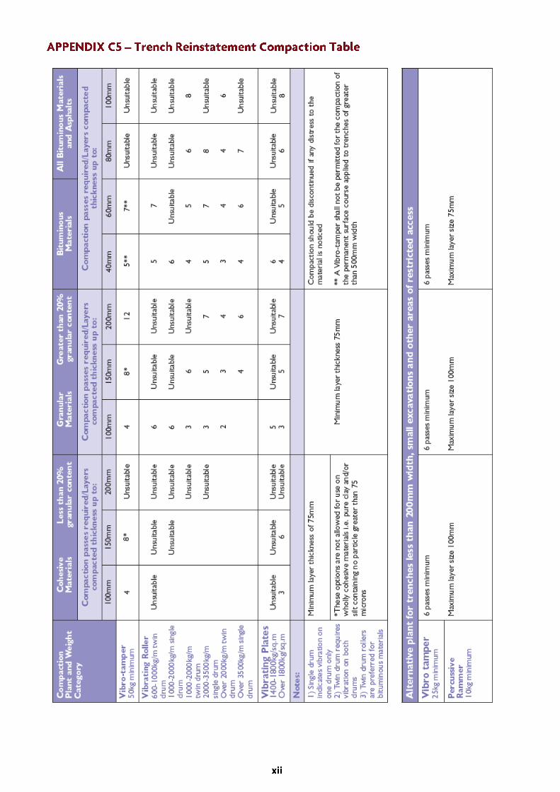

50 pen Bitumen
Surface Course
Binder/Base
190
170
100 pen Bitumen
Surface Course only 160
100 pen Bitumen
Macadam
160
50 pen Bitumen
Surface Course
Binder/Base
140
120
100 pen Bitumen
Surface Course only 120
100 pen Bitumen
Macadam
120
50 pen Bitumen
All Courses
85 100 pen Bitumen
Surface Course only 75
100 pen Bitumen
Macadam
95
Temperatures by which all compaction should be substantially completed
Temperature
immediately prior
to rolling
*At or near these temperatures the supplier should be requested to increase the delivery temperature in accordance with Clause 4.2 BS594, 2003.
The above temperatures are dependent on adoption of minimum layer thickness in accordance with Table 6 of part 2 BS4987, 2003


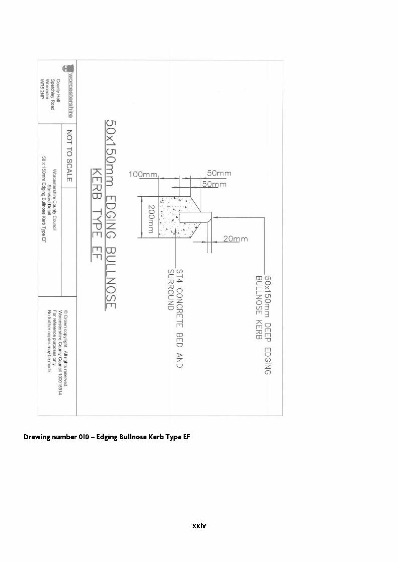


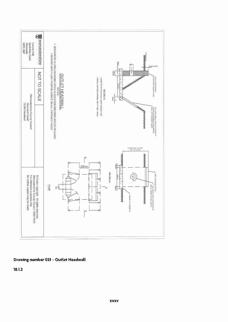

Worcestershire Local Transport Plan 3
Worcestershire Local Transport Plan 3
Find out more online:www.worcestershire.gov.uk/LTP3
DRAFT
Find out more online:www.worcestershire.gov.uk/LTP3
5454
7 07
/10
You can contact us in the following ways:
For further information please contact:
By telephone: 01905 765765
By post: Worcestershire County Council, County Hall, Spetchley Road, Worcester WR5 2NP
By email: [email protected]
Online: www.worcestershire.gov.uk/LTP3
To the best of our knowledge all information was correct at the time of printing: March 2011.
This document can be made available in other formats (large print, audio tape, computer disk and Braille) on request from the Worcestershire Hub using the contact details above.