Embed Size (px)
Citation preview

flender.com
FLENDER COUPLINGS CATALOG FLE 10.3 EDITION 2020 EN
HIGHLY FLEXIBLE COUPLINGSELPEX-B, ELPEX-S AND ELPEX
FLE 10 CATALOG GROUP
flender.com
FLENDER COUPLINGS CATALOG FLE 10.1 EDITION 2020 EN
TORSIONALLY RIGID COUPLINGSZAPEX, N-ARPEX AND ARPEX
flender.com
FLENDER COUPLINGS CATALOG FLE 10.2 EDITION 2020 EN
FLEXIBLE COUPLINGSN-EUPEX, RUPEX AND N-BIPEX
flender.com
FLENDER COUPLINGS CATALOG FLE 10.3 EDITION 2020 EN
HIGHLY FLEXIBLE COUPLINGSELPEX-B, ELPEX-S AND ELPEX
flender.com
FLENDER COUPLINGS CATALOG FLE 10.4 EDITION 2020 EN
FLUID COUPLINGSFLUDEX
Product catalog FLE 10.1 Torsionally Rigid Couplings
Product catalog FLE 10.2 Flexible Couplings
Product catalog FLE 10.3 Highly Flexible Couplings
Product catalog FLE 10.4 Fluid Couplings
For further coupling catalogs, see page A/6
HIGHLY FLEXIBLE COUPLINGS
Catalog FLE 10.3 Edition 2020 EN
Introduction E E
Torsionally Rigid Gear Couplings ZAPEX ZW 4 4
ZAPEX ZN 5 5
Torsionally Rigid All-Steel Couplings N-ARPEX, ARPEX 6 6
Flexible Couplings N-EUPEX 7 7
RUPEX 8 8
N-BIPEX 9 9
Highly Flexible Couplings ELPEX-B 10 10
ELPEX-S 11 11
ELPEX 12 12
Fluid Couplings FLUDEX 13 13
Appendix A A
FLENDER STANDARD COUPLINGS

The mechanical drive train comprises individual units such as motor, gear unit and driven machine. The coupling connects these component assemblies. As well as the transmission of rotary motion and torque, other requirements may be made of the coupling.
• Compensation for shaft misalignment with low restorative forces
• Control of characteristic angular vibration frequency and damping
• Interruption or limitation of torque• Noise insulation, electrical insulation
Couplings are frequently chosen after the machines to be connected have already been selected. Thanks to a large number of different coupling assembly options, speci-fied marginal conditions for clearance and connection geometry can be met from the standard range. The coup-ling also performs secondary functions, e.g. providing a brake disk or brake drum for operating or blocking brakes, devices to record speed or the attachment of sprockets or pulleys.
Couplings are divided into two main groups, couplings and clutches. Clutches interrupt or limited the transmissible torque. The engaging and disengaging forces on externally operated clutches are introduced via a mechanically, electrically, hydraulically or pneumatically operating mechanism. Overload, centrifugal or freewheel clutches draw their engaging energy from the transmitted output.
Rigid couplings, designed as clamp, flanged or mechanism couplings, connect machines which must not undergo any shaft misalignment. Hydrodynamic couplings, often also called fluid or Föttinger couplings, are used as starting couplings in drives with high mass moments of inertia of the driven machine. In drive technology very often flexible, positive couplings, which may be designed to be torsionally rigid, torsionally flexible or highly flexible, are used.
Torsionally rigid couplings are designed to be rigid in a peripheral direction and flexible in radial and axial direc-tions. The angle of rotation and torque are conducted through the coupling without a phase shift.
Torsionally flexible couplings have resilient elements usually manufactured from elastomer materials. Using an elastomer material with a suitable ShoreA hardness provides the most advantageous torsional stiffness and damping for the application. Shaft misalignment causes the resilient elements to deform.
Highly flexible couplings have large-volume (elastomer) resilient elements of low stiffness. The angle of rota-tion and torque are conducted through the coupling with a considerable phase shift.
INTRODUCTION
E/2
FLENDER STANDARD COUPLINGS | INTRODUCTION
E E
4 4
5 5
6 6
7 7
8 8
9 9
10 10
11 11
12 12
13 13
A A
Shaft couplings
Couplings Clutches
G_M
D10
_EN
_000
01a
Clamp couplingsFlanged couplings
Mechanism couplings
rigid flexible
Clutches
externally operated
Safety couplings
torque-controlled
Centrifugal clutches
speed controlled
Freewheel clutchesOverrunning clutches
rotation direction controlled
friction
HydrodynamiccouplingsMagneticcouplings
Friction couplings
positive
Torsionally rigid Torsionally flexible Highly flexible
Gear couplingsAll-steel membrane
couplingsUniversal-joint couplingsParallel-crank couplings
Steel-spring couplingsPin-and-bush
couplingsPin couplings
Rubber elementcouplings
Rubber-tirecouplings
Rubber-diskcouplings
Rubber spacer ringcouplings
E/3
FLENDER STANDARD COUPLINGS | INTRODUCTION
E E
4 4
5 5
6 6
7 7
8 8
9 9
10 10
11 11
12 12
13 13
A A

OUR COUPLING GROUPS AT A GLANCE
N-EUPEX, RUPEX and N-BIPEX
Flexible CouplingsFlexible Flender couplings have a wide range of possible applications. A broad standard modular system as well as specially designed application-specific coup-lings are available.
ELPEX, ELPEX-B and ELPEX-S
Highly Flexible CouplingsELPEX® couplings are free of circumferential back-lash. Their damping capacity and low torsional stiff-ness make them especially well-suited for coupling machines with strongly non-uniform torque characteristics or large shaft misalignment.
N-EUPEX cam couplingsRated torque: 19 Nm … 62,000 Nm
ELPEX elastic ring couplingsRated torque: 1,600 Nm … 90,000 Nm
ELPEX-B elastic tire couplingsRated torque: 24 Nm … 14,500 Nm
N-BIPEX cam couplingsRated torque: 12 Nm … 4,650 Nm
ELPEX-S rubber disk couplingsRated torque: 330 Nm … 63,000 Nm
RUPEX pin-and-bush couplingsRated torque: 200 Nm … 1,300,000 Nm
E/4
FLENDER STANDARD COUPLINGS | INTRODUCTION
E E
4 4
5 5
6 6
7 7
8 8
9 9
10 10
11 11
12 12
13 13
A A

FLUDEX
Hydrodynamic couplingsThe FLUDEX hydrodynamic fluid coupling works accor-ding to the Föttinger principle. It functions entirely free of wear.
FLUDEX fluid CouplingsPower: 1.2 kW … 2,500 kW
Application-specific couplingsCouplings for rail vehicles must meet high demands. Due to their high degree of standardization and wide variety, they can be used in the most diverse vehicle types.
Each wind turbine coupling is designed to optimally meet the requirements of the respective wind turbine. The coupling connects the fast-running gear shaft with the generator shaft and is available for wind turbines with a capacity of up to 12 MW.
Wind turbine couplingsRated torque: 10,000 Nm … 60,000 Nm
Railway couplingRated torque: 1,000 Nm … 9,500 Nm
ZAPEX gear couplings and ARPEX all-steel couplings
Torsionally rigid couplingsFor transmission of high torques, we offer both ARPEX all-steel couplings and ZAPEX gear couplings in a range of versions. Their purposes of application vary accor-ding to specific requirements with respect to shaft misalignment, temperature and torque.
BIPEX-S and SIPEX
Backlash-free couplingsThe vibration-damping, electrically insulating plug-in BIPEX-S elastomer couplings and SIPEX metal bellows couplings with very high torsional stiffness deliver especially isogonal torque transmission.
N-ARPEX and ARPEX all-steel couplingsRated torque: 92 Nm … 2,000,000 Nm
ZAPEX gear couplingsRated torque: 1,300 Nm … 7,200,000 Nm
ARPEX high Performance CouplingsRated torque: 1,000 Nm … 588,500 Nm
BIPEX-S and SIPEXRated torque: 0.1 Nm … 5,000 Nm
E/5
FLENDER STANDARD COUPLINGS | INTRODUCTION
E E
4 4
5 5
6 6
7 7
8 8
9 9
10 10
11 11
12 12
13 13
A A

E/6

TECHNICAL INFORMATION AND COUPLING SELECTION
Technical Information E/8Shaft misalignment E/8Balancing E/9Shaft-hub connections E/11Standards E/12Key to symbols E/13
Selection of the coupling series E/14Typical coupling solutions for different example applications E/15
Selection of the coupling size E/16Coupling load in continuous operation E/16Coupling load at maximum and overload conditions E/17Coupling load due to dynamic torque load E/17Checking the maximum speed E/18Checking permitted shaft misalignment E/18Checking bore diameter, mounting geometry and coupling design E/18Coupling behavior under overload conditions E/18Checking shaft-hub connection E/18Checking low temperature and chemically aggressive environment E/18
Features of the standard type E/19
E/7
FLENDER STANDARD COUPLINGS | INTRODUCTION
E E
4 4
5 5
6 6
7 7
8 8
9 9
10 10
11 11
12 12
13 13
A A

Shaft misalignment
Shaft misalignment is the result of displacement during assembly and operation and, where machines const-ructed with two radial bearings each are rigidly coupled, will cause high loads being placed on the bearings. Elastic deformation of base frame, foundation and machine housing will lead to shaft misalignment which cannot be prevented, even by precise alignment.
Furthermore, because individual components of the drive train heat up differently during operation, heat expansion of the machine housings causes shaft misalignment. Poorly aligned drives are often the cause of seal, rolling bearing or coupling failure. Alignment should be carried out by specialist personnel in accordance with operating instructions.
TECHNICAL INFORMATION
Depending on the direction of the effective shaft misalignment a distinction is made between:
Single-joint couplings
Couplings with flexible elements mainly made of elas-tomer materials. Shaft misalignment results in deforma-tion of the elastomer elements. The elastomer elements can absorb shaft misalignment as deformations in an axial, radial and angular direction. The degree of permissible misalignment depends on the coupling size, the speed and the type of elastomer element. Single-joint couplings do not require an adapter and are therefore short versions.
Example:In the case of a RUPEX RWN 198 coupling with an outer diameter of 198 mm and a speed of 1500 rpm, the permitted radial misalignment is ΔKr = 0.3 mm.
Kr
G_M
D10
_XX
_000
14
Couplings can be categorized into one of the following groups:
Axial misalignment Radial misalignment Angular misalignment
Two-joint couplings
Two-joint couplings are always designed with an adapter. The two joint levels are able to absorb axial and angular misalignment. Radial misalignment occurs via the gap between the two joint levels and the angular displace-ment of the joint levels. The permitted angular misalign-ment per joint level is frequently about 0.5°. The permitted shaft misalignment of the coupling can be adjusted via the length of the adapter. If there are more than two joint levels, it is not possible to define the position of the coupling parts relative to the axis of rotation. (The less frequently used parallel-crank couplings are an exception).
Example:N-ARPEX ARN-6 NEN 217-6 with a shaft distance of 140 mm with a permitted radial misalignment of ΔKr = 2.2 mm (angle per joint level 1.0°).
E/8
FLENDER STANDARD COUPLINGS | INTRODUCTION
E E
4 4
5 5
6 6
7 7
8 8
9 9
10 10
11 11
12 12
13 13
A A

Balancing
Balance quality levelsThe so-called quality level G to DIN ISO 21940 indicates a range of permitted residual imbalance from zero up to an upper limit. Applications can be grouped on the basis of similarity analysis. For many applications a coupling balance quality of G 16 is sufficient. On drives susceptible to vibration the balance quality should be G 6.3. Only in special cases is a better balance quality required.
Balancing standard in accordance with DIN ISO 21940-32Besides the required balance quality, it is necessary to set standards which define how the mass of the parallel key is to be taken into consideration when balancing. In the past, motor rotors have frequently been balanced in accordance with the full parallel key standard. The "appropriate" balance condition of the coupling hub was described as "balancing with open keyway" or "balancing after key seating". Today it is usual for the motor rotor, as well as the gear unit and driven machine shaft, to be balanced in accordance with the half parallel key standard.
Full parallel key standard
The parallel key is inserted in the shaft keyway, then balancing is carried out. The coupling hub must be balanced without parallel key after keyseating.
Marking of shaft and hub with "F" (for "full").
Half parallel key standard
The balancing standard normally applied today. Before balancing, a half parallel key is inserted in the shaft and another in the coupling hub. Alternatively, balancing can be carried out before cutting the keyway.
The balanced parts must be marked with an "H". This marking can be dispensed with if it is absolutely clear which parallel key standard has been applied.
No parallel key standard
Balancing of shaft and coupling hub after keyseating, but without parallel key. Not used in practice. Marking of shaft and hub with "N" (for "no"). The length of the parallel key is determined by the shaft keyway. Coupling hubs may be designed considerably shorter than the shaft.
To prevent imbalance forces caused by projecting parallel key factors when balancing in accordance with the half parallel key standard in the case of applications with high balancing quality requirements, grooved spacer rings can be fitted or stepped parallel keys used.
Flender Balancing Standard
The balancing quality level, together with the operating speed, results in the maximum permissible eccentri-city of the center of gravity of the coupling or the coupling subassembly. In the Flender article number the balancing quality can be preset with the help of the order code. Addi-tionally, also the balance quality level to DIN ISO 21940 can be preset together with the operating speed belonging to it, which then be taken as priority.
eperm = 9550⋅―
ecoupl ≤ eperm
Gn
Permitted eccentricity of center of gravity eperm in µm Eccentricity of center of gravity of coupling ecoupl in µm Balancing quality level G in mm/s Coupling speed n in rpm
Eccentricity of center of gravity of coupling ecoupl
Flender balancing quality
Order code
maximum 100 μm standard balancing without specificationmaximum 40 μm fine balancing W02maximum 16 μm micro-balancing W03better than 16 μm special balancing on request
E/9
FLENDER STANDARD COUPLINGS | INTRODUCTION
E E
4 4
5 5
6 6
7 7
8 8
9 9
10 10
11 11
12 12
13 13
A A

TECHNICAL INFORMATION
G 1
G 4
G 10G 16G 25G 40
102
10
1
2
468
2
468
2
468
103
102 42 6 8 2 4 6 8103 104
G 1.6G 2.5
G 6.3
G_M
D10
_EN
_000
07a
Ecc
entri
city
of c
ente
r of g
ravi
ty e
perm
. in
µm
Coupling speed in rpm
On request
Micro-balancing
Fine balancing
Standard balancing
Example:Coupling speed = 1450 rpmrequired balancing quality level G 6.3
eperm = 9550⋅― = 9550⋅― µmG 6.3n 1450
Thus, the required eccentricity of center of gravity is 41.5 μm. The fine balancing with a maximum eccentricity of center of gravity of 40 mm fulfills this requirement; there-fore, the order code W02 has to be specified when orde-ring.
For many applications the following balancing quality recommendation applies:
Coupling standard balancing fine balancingν = DA ⋅ n/19100
short version with LG ≤ 3 × DA ν ≤ 30 m/s ν > 30 m/slong version with LG > 3 × DA ν ≤ 15 m/s ν > 15 m/s
Peripheral speed ν in mm/s Coupling outer diameter DA in mm Coupling speed n in rpm
Coupling length LG in mm
The following standards on balancing must be observed:
• couplings are balanced in subassemblies.• hub parts without finished bore are unbalanced.• the number of balancing levels (one- or two-level
balancing) is specified by Flender.• without special specification balancing is done in ac-
cordance with the half-parallel-key standard. Balancing in accordance with the full-parallel-key standard must be specified in the order number.
• For FLUDEX couplings special balancing standards spe-cified in Section 13 apply.
• ARPEX couplings in standard balancing quality are un-balanced. Thanks to steel components machined all over and precisely guided adapters the balancing quality of standard balancing is nearly always adhered to.
E/10
FLENDER STANDARD COUPLINGS | INTRODUCTION
E E
4 4
5 5
6 6
7 7
8 8
9 9
10 10
11 11
12 12
13 13
A A

Shaft-hub connections
The bore and the shaft-hub connection of the coupling are determined by the design of the machine shaft. In the case of IEC standard motors, the shaft diameters and parallel key connections are specified in accordance with DIN EN 50347. For diesel motors, the flywheel connections are frequently specified in accordance with SAE J620d or DIN 6288. Besides the very widely used connection of shaft and hub with parallel keys to DIN 6885 and cylindrically bored hubs, couplings with Taper clamping bushes, clam-ping sets, shrink-fit connections and splines to DIN 5480 are common.
The form stability of the shaft/hub connection can only be demonstrated when shaft dimensions and details of the connection are available. The coupling torques specified in the tables of power ratings of the coupling series do not apply to the shaft-hub connection unrestrictedly.
In the case of the shaft-hub connection with parallel key, the coupling hub must be axially secured, e.g. with a set screw or end washer. The parallel key must be secured against axial displacement in the machine shaft.
All Flender couplings with a finished bore and parallel keyway are designed with a set screw. Exceptions are some couplings of the FLUDEX series, in which end washers are used. During assembly, Taper clamping bushes are frictionally connected to the machine shaft.
E/11
FLENDER STANDARD COUPLINGS | INTRODUCTION
E E
4 4
5 5
6 6
7 7
8 8
9 9
10 10
11 11
12 12
13 13
A A

TECHNICAL INFORMATION
Standards
Machines2006/42/EG EC Machinery Directive
2014/34/EU ATEX Directive – Manufacturer
1999/92/EG ATEX Directive – Operator – and ATEX Guideline to Directive 1999/92/EC
DIN EN 80079-36 Non-electrical equipment for use in potentially explosi-ve atmospheres
DIN EN 1127 Explosive atmospheres, explosion prevention and protection
DIN EN 50347 General-purpose three-phase induction motors having standard dimensions and outputs
CouplingsDIN 740 Flexible shaft couplings Part 1 and Part 2
VDI Guideline 2240
Shaft couplings - Systematic subdivision according to their properties VDI Technical Group Engineering Design 1971
API 610 Centrifugal Pumps for Petroleum, Chemical and Gas Industry Services
API 671 Special Purpose Couplings for Petroleum, Chemical and Gas Industry Services
ISO 10441Petroleum, petrochemical and natural gas industries – Flexible couplings for mechanical power transmission-special-purpose applications
ISO 13709 Centrifugal pumps for petroleum, petrochemical and natural gas industries
BalancingDIN ISO 21940 Requirements for the balancing quality of rigid rotors
DIN ISO 21940-32Mechanical vibrations; standard governing the type of parallel key during balancing of shafts and composi-te parts
Shaft-hub connections
DIN 6885 Driver connections without taper action – parallel keys – keyways
SAE J620d Flywheels for industrial engines ...
DIN 6288Reciprocating internal combustion engines Dimensions and requirements for flywheels and flexible couplings
ASME B17.1 Keys and keyseats
DIN EN 50347 General-purpose three-phase induction motors with standard dimensions and output data
BS 46-1:1958 Keys and keyways and taper pins Specification
E/12
FLENDER STANDARD COUPLINGS | INTRODUCTION
E E
4 4
5 5
6 6
7 7
8 8
9 9
10 10
11 11
12 12
13 13
A A
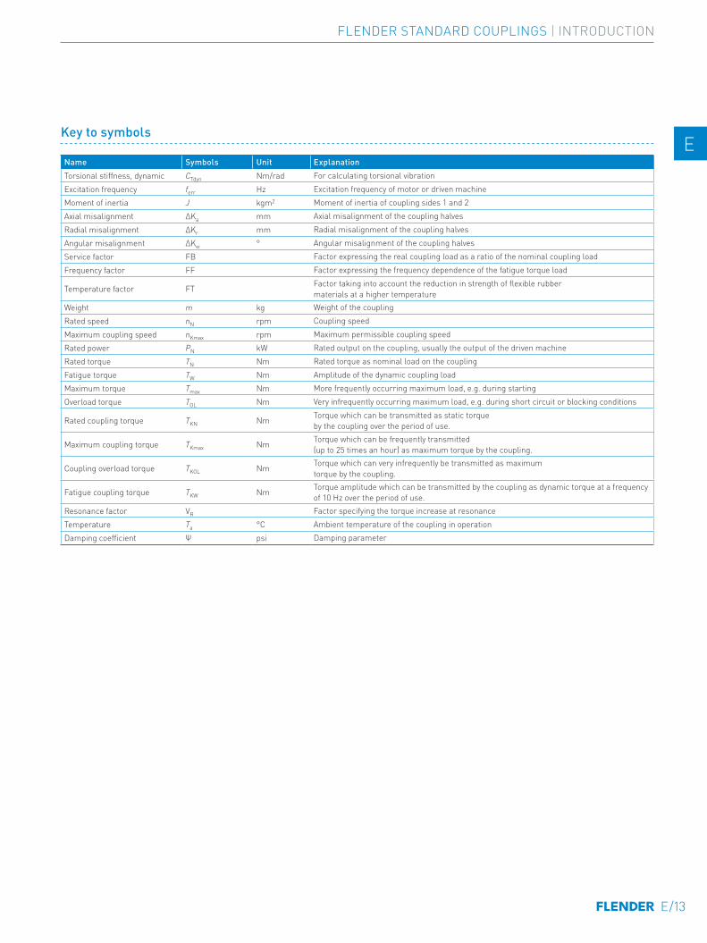
Key to symbols
Name Symbols Unit Explanation Torsional stiffness, dynamic CTdyn Nm/rad For calculating torsional vibrationExcitation frequency ferr Hz Excitation frequency of motor or driven machine Moment of inertia J kgm2 Moment of inertia of coupling sides 1 and 2 Axial misalignment ∆Ka mm Axial misalignment of the coupling halves Radial misalignment ∆Kr mm Radial misalignment of the coupling halvesAngular misalignment ∆Kw ° Angular misalignment of the coupling halvesService factor FB Factor expressing the real coupling load as a ratio of the nominal coupling loadFrequency factor FF Factor expressing the frequency dependence of the fatigue torque load
Temperature factor FT Factor taking into account the reduction in strength of flexible rubber materials at a higher temperature
Weight m kg Weight of the couplingRated speed nN rpm Coupling speedMaximum coupling speed nKmax rpm Maximum permissible coupling speed Rated power PN kW Rated output on the coupling, usually the output of the driven machine Rated torque TN Nm Rated torque as nominal load on the couplingFatigue torque TW Nm Amplitude of the dynamic coupling loadMaximum torque Tmax Nm More frequently occurring maximum load, e.g. during startingOverload torque TOL Nm Very infrequently occurring maximum load, e.g. during short circuit or blocking conditions
Rated coupling torque TKN Nm Torque which can be transmitted as static torque by the coupling over the period of use.
Maximum coupling torque TKmax Nm Torque which can be frequently transmitted (up to 25 times an hour) as maximum torque by the coupling.
Coupling overload torque TKOL Nm Torque which can very infrequently be transmitted as maximum torque by the coupling.
Fatigue coupling torque TKW Nm Torque amplitude which can be transmitted by the coupling as dynamic torque at a frequency of 10 Hz over the period of use.
Resonance factor VR Factor specifying the torque increase at resonanceTemperature Ta °C Ambient temperature of the coupling in operationDamping coefficient Ψ psi Damping parameter
E/13
FLENDER STANDARD COUPLINGS | INTRODUCTION
E E
4 4
5 5
6 6
7 7
8 8
9 9
10 10
11 11
12 12
13 13
A A

The coupling series is frequently determined by the driven machine and the design of the drive train. Common selec-tion criteria are listed below and assigned to coupling properties, which are used to select the coupling series. Additionally, the price of the coupling and availability are important criteria for determining the coupling series to be used.
The FLUDEX series operates positively and transmits the torque with the aid of a flowing oil or water filling.
SELECTION OF THE COUPLING SERIES
FLUDEX couplings are used to reduce starting and/or overload torques. During starting, the motor may, for example, run up within a very short time; because of the FLUDEX coupling, the drive train with the driven machine may accelerate after a delay and without increased torque load.
The FLUDEX coupling cannot compensate for shaft misa-lignment and is therefore designed in combination with a displacement coupling, a cardan shaft or a belt drive. The displacement coupling may be selected in accordance with the criteria described below.
Selection criteriaTorque range Speed range Torsional stiffness Operating
temperature rangeRated coupling torque TKN
Peripheral speed vmax = DA ⋅ nmax/19100
torsionally rigid torsionally flexible
Highly flexible
ZAPEX 850 ... 7200000 Nm 60 m/s ■ – – -20 ... +80 °CN-ARPEX 350 ... 2000000 Nm 110 m/s ■ – – -50 ... +280 °CARPEX 92 ... 2000000 Nm 100 m/s ■ – – -40 ... +280 °CN-EUPEX 19 ... 62000 Nm 36 m/s – ■ – -50 ... +100 °CN-EUPEX DS 19 ... 21200 Nm 36 m/s – ■ – -30 ... +80 °CRUPEX 200 ... 1300000 Nm 60 m/s – ■ – -50 ... +100 °CN-BIPEX 12 ... 4650 Nm 45 m/s – ■ – -50 ... +100 °CELPEX-B 24 ... 14500 Nm 35 m/s – – ■ -50 ... +70 °CELPEX-S 330 ... 63000 Nm 66 m/s – – ■ -40 ... +120 °CELPEX 1600 ... 90000 Nm 60 m/s – – ■ -40 ... +80 °C
E/14
FLENDER STANDARD COUPLINGS | INTRODUCTION
E E
4 4
5 5
6 6
7 7
8 8
9 9
10 10
11 11
12 12
13 13
A A

Typical coupling solutions for different example applications
The specified application factors are recommendations; regulations, rules and practical experience take priority as assessment criteria.No application factor need be taken into account with FLUDEX couplings.
In the case of highly flexible couplings of the ELPEX, ELPEX-S and ELPEX-B series, deviating application factors are stated in the product descriptions.FLUDEX couplings are mostly mounted on the high-speed gear shaft.
Example applications Appli-cation factor FB
Electric motor without gear unitCentrifugal pumps 1.0Piston pumps 1.5Vacuum pumps 1.5Fans with TN less than 75 Nm 1.5Fans with TN from 75 to 750 Nm 1.75Fans with TN larger than 750 Nm 1.75Blowers 1.5Frequency converters / generators 1.25Reciprocating compressors 1.75Screw-type compressors 1.5
Internal-combustion engine without gear unit
Generators 1.75Pumps 1.5Fans 1.75
Hydraulic pumps, excavators, construction machines 1.5
Compressors / screw-type compressors 1.5
Agricultural machinery 1.75Other Turbine gear units 1.5Hydraulic motor - gear unit 1.25Electric motor with gear unit Chemical industryExtruders 1.5Pumps - centrifugal pumps 1.0Pumps - piston pumps 1.75Pumps - plunger pumps 1.5Reciprocating compressors 1.75Calenders 1.5Kneaders 1.75Cooling drums 1.25Mixers 1.25Stirrers 1.25Toasters 1.25Drying drums 1.25Centrifuges 1.25Crushers 1.5Power generation and conversion
Compressed air, reciprocating compressors 1.75
Example applications Appli-cation factor FB
Compressed air, screw-type compressors 1.25
Air - Blowers 1.5Air - Cooling tower fans 1.5Air - Turbine blowers 1.5Generators, converters 1.25Welding generators 1.25Metal production, iron and steel worksPlate tilters 1.5Ingot pushers 1.75Slabbing mill 1.75Coiling machines 1.5Roller straightening machines 1.5Roller tables 1.75Shears 1.75Rollers 1.75Metal working machinesPlate bending machines 1.5Plate straightening machines 1.5Hammers 1.75Planing machines 1.75 Presses, forging presses 1.75Shears 1.5Grinding machines 1.25 Punches 1.5Machine tools: Main drives 1.5Machine tools: Auxiliary drives 1.25Food industryFilling machines 1.25Kneading machines 1.5Mashers 1.5Sugar cane production 1.5Production machines
Construction machines, hydraulic pumps 1.25
Construction machines, traversing gears 1.5
Construction machines, suction pumps 1.5
Construction machines, concrete mixers 1.5
Printing machines 1.25 Woodworking - barking drums 1.5Woodworking - planing machines 1.5
Example applications Appli-cation factor FB
Woodworking - reciprocating saws 1.5Grinding machines 1.5Textile machines - winders 1.5 Textile machines - printing machines 1.5 Textile machines - tanning vats 1.5 Textile machines - shredders 1.5 Textile machines - looms 1.5Packaging machines 1.5Brick molding machines 1.75 Transport and logisticsPassenger transport - elevators 1.5 Passenger transport - escalators 1.5 Conveyor systems - bucket elevators 1.5 Conveyor systems - hauling winches 1.5 Conveyor systems - belt conveyors 1.5
Conveyor systems - endless-chain conveyors 1.5
Conveyor systems - circular conveyors 1.5Conveyor systems - screw conveyors 1.5 Conveyor systems - inclined hoists 1.5Crane traversing gear 1.5Hoisting gear 1.5 Crane lifting gear 2.0Crane traveling gear 1.5Crane slewing gear 1.5 Crane fly jib hoists 1.5Cable railways 1.5 Drag lifts 1.5 Winches 1.5 Cellulose and paperPaper-making machines, all 1.5 Pulper drives 1.5 Cement industryCrushers 1.75 Rotary furnaces 1.5 Hammer mills 1.75 Ball mills 1.75 Pug mills 1.75 Mixers 1.5Pipe mills 1.5Beater mills 1.75Separators 1.5 Roller presses 1.75
E/15
FLENDER STANDARD COUPLINGS | INTRODUCTION
E E
4 4
5 5
6 6
7 7
8 8
9 9
10 10
11 11
12 12
13 13
A A
SELECTION OF THE COUPLING SIZE
The torque load of the coupling must be determined from the output of the driven machine and the coupling speed.
Rated coupling load TN = 9550 × PN / nN(TN in Nm; PN in kW; nN in rpm)
The rated coupling load obtained in this way must be multiplied by factors and compared with the rated coup-ling torque. An ideal but expensive method is to measure the torque characteristic on the coupling. For this, Flender offers special adapters fitted with torque measuring devices.
The rated coupling torque TKN is the torque which can be transmitted by the coupling over an appropriate period of use if the load is applied to the coupling purely statically at room temperature.
Application factors are to express the deviation of the real coupling load from the "ideal" load condition.
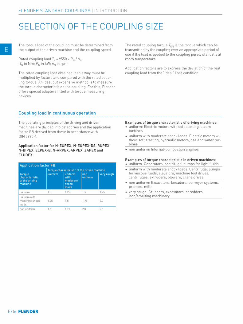
Coupling load in continuous operation
The operating principles of the driving and driven machines are divided into categories and the application factor FB derived from these in accordance with DIN 3990-1.
Application factor for N-EUPEX, N-EUPEX-DS, RUPEX, N-BIPEX, ELPEX-B, N-ARPEX, ARPEX, ZAPEX and FLUDEX
Application factor FBTorque characteristic of the driven machine
Torque characteristic of t he driving machine
uniform uniform with moderate shock loads
non uniform
very rough
uniform 1.0 1.25 1.5 1.75
uniform with moderate shock loads
1.25 1.5 1.75 2.0
non uniform 1.5 1.75 2.0 2.5
Examples of torque characteristic of driving machines:• uniform: Electric motors with soft starting, steam
turbines• uniform with moderate shock loads: Electric motors wi-
thout soft starting, hydraulic motors, gas and water tur-bines
• non uniform: Internal-combustion engines
Examples of torque characteristic in driven machines:• uniform: Generators, centrifugal pumps for light fluids• uniform with moderate shock loads: Centrifugal pumps
for viscous fluids, elevators, machine tool drives, centrifuges, extruders, blowers, crane drives
• non uniform: Excavators, kneaders, conveyor systems, presses, mills
• very rough: Crushers, excavators, shredders, iron/smelting machinery
E/16
FLENDER STANDARD COUPLINGS | INTRODUCTION
E E
4 4
5 5
6 6
7 7
8 8
9 9
10 10
11 11
12 12
13 13
A A

NR = natural rubber, natural-synthetic rubber mixtureNBR = nitril-butadiene-rubber (Perbunan)HNBR = hydrated acrylonitrile butadiene rubberCR = chloroprene rubber (FRAS fire-resistant and anti-static)VMQ = siliconeTPU = polyurethane
Coupling size TKN ≥ TN ⋅ FB ⋅ FT
In the case of ARPEX and ZAPEX coupling types, no temperature factor (FT = 1.0) need be taken into account.
Temperature factor FTTemperature Ta on the coupling
Coupling Elastomer material
Low t emperature °C
under -30 °C
-30 °C up to 50 °C
up to 60 °C
up to 70 °C
up to 80 °C
up to 90 °C
up to 100 °C
up to 110 °C
up to 120 °C
N-EUPEX NBR -30 – 1.0 1.0 1.0 1.0 – – – –N-EUPEX NR -50 1.1 1) 1.0 – – – – – – –N-EUPEX HNBR -10 – 1.0 1.0 1.0 1.0 1.25 1.25 – –N-EUPEX DS NBR -30 – 1.0 1.0 1.0 1.0 – – – –RUPEX NBR -30 – 1.0 1.0 1.0 1.0 – – – –RUPEX NR -50 1.1 1.0 – – – – – – –RUPEX HNBR -10 – 1.0 1.0 1.0 1.0 1.25 1.25 – –N-BIPEX TPU -50 1.0 1.0 1.0 1.0 1.0 1.0 1.0 – –ELPEX NR -40 1.1 1.0 1.25 1.40 1.60 – – – –ELPEX-B NR -50 1.1 1.0 – – – – – – –ELPEX-B CR -15 – 1.0 1.0 1.0 – – – – –ELPEX-S SN, NN, WN NR -40 1.1 1.0 1.25 1.40 1.60 – – – –
ELPEX-S NX VMQ -40 1.1 1.0 1.0 1.0 1.0 1.1 1.25 1.4 1.6
1) The N-EUPEX coupling is not suitable for shock loads when used at low temperatures.
Coupling load at maximum and overload conditions
The maximum torque is the highest load acting on the coupling in normal operation. Maximum torques at a frequency of up to 25 times an hour are permitted and must be lower than the maximum coup-ling torque. Examples of maximum torque conditions are: Starting operations, stopping operations or usual opera-ting conditions with maximum load.
TKmax ≥ TMax ⋅ FT
Overload torques are maximum loads which occur only in combination with special, infrequent operating conditions. Examples of overload torque conditions are: Motor short circuit, emergency stop or blocking because of component breakage. Overload torques at a frequency of once a month are permitted and must be lower than the maximum over-load torque of the coupling. The overload condition may last only a short while, i.e. fractions of a second.
TKOL ≥ TOL ⋅ FT
Coupling load due to dynamic torque load
Applying the frequency factor FF, the dynamic torque load must be lower than the coupling fatigue torque.
Dynamic torque load
TKW ≥ TW ⋅ FF
Frequency of the dynamic torque load ferr ≤ 10 Hz frequency factor FF = 1.0
Frequency of the dynamic torque load ferr > 10 Hz frequency factor FF = √(ferr/10 Hz)
For the ZAPEX and ARPEX series, the frequency factor is always FF = 1.0.
E/17
FLENDER STANDARD COUPLINGS | INTRODUCTION
E E
4 4
5 5
6 6
7 7
8 8
9 9
10 10
11 11
12 12
13 13
A A
Checking the maximum speed
For all load situations nKmax ≥ nmax
Checking permitted shaft misalignment
For all load situations, the actual shaft misalignment must be less than the permitted shaft misalignment.
Checking bore diameter, mounting geometry and coupling design
The check must be made on the basis of the dimension tables. The maximum bore diameter applies to parallel keyways to DIN 6885. For other keyway geometries, the maximum bore diameter can be reduced.
On request, couplings with adapted geometry can be provided.
Coupling behavior under overload conditions
The ZAPEX, N-ARPEX, ARPEX, N-EUPEX, RUPEX and N-BIPEX coupling series can withstand overloads until the breakage of metal parts. These coupling series are desig-nated as fail-safe.The N-EUPEX DS, ELPEX-B, ELPEX-S and ELPEX coup-ling series throw overload. The elastomer element of these couplings is irreparably damaged without damage to metal parts when subjected to excessive overload.
These coupling series are designated as non-fail-safe. These types that fail can be fitted with a so-called fail-safe device. This additional component enables emergency operation, even after the rubber element of the coupling has been irreparably damaged.
Checking shaft-hub connection
The torques specified in the tables of power ratings data of the coupling series do not necessarily apply to the shaft-hub connection. Depending on the shaft-hub connection, proof of form stability is required. Flender recommends obtaining proof of form strength by using calculation methods in accordance with the current state of the art.
Shaft-hub connection Suggestion for calculation method
Keyway connection to DIN 6885-1 DIN 6892Shrink fit DIN 7190Spline to DIN 5480Bolted flange connection VDI 2230Flange connection with close-fitting bolts
Fitting recommendations for the shaft-hub connection are given in the Appendix.
The coupling hub is frequently fitted flush with the shaft end face. If the shaft projects, the risk of collision with other coupling parts must be checked. If the shaft is set back, in addition to the load-bearing capacity of the shaft-hub connection, the correct positioning of the hub must be ensured as well. If the bearing hub length is insuf-ficient, restorative forces may cause tilting movements and so wear to and impairment of the axial retention. Also, the position of the set screw to be positioned on sufficient shaft or parallel key material must be noted.
Checking low temperature and chemically aggressive environment
The minimum permitted coupling temperature is specified in the Temperature factor FT table. In the case of chemi-cally aggressive environments, please consult the manu-facturer.
SELECTION OF THE COUPLING SIZE
E/18
FLENDER STANDARD COUPLINGS | INTRODUCTION
E E
4 4
5 5
6 6
7 7
8 8
9 9
10 10
11 11
12 12
13 13
A A

Configurator
The article number can be obtained with the help of the Configurator. The coupling can be selected in a product configurator and specified using selection menus.
The Configurator is available under flender.com.
The coupling can be selected via "Technical selection" (technical selection) or via "Direct selection" (via article-no.).
Couplings Features of the standard typeAll coupling series except ARPEX clamping hubs and FLUDEX with keyway to ASME B17.1 Bore tolerance H7
N-ARPEX and ARPEX clamping hubs Bore tolerance H6
FLUDEX couplings with keyway to ASME B17.1Hollow shafts: bore tolerance K7other parts: Bore tolerance M7
All coupling series with bore diameter - imperial Parallel keyway to ASME B17.1Bore diameter metric in the case of ZAPEX, N-ARPEX and ARPEX coupling series as well as coupling hubs with applied brake disks or brake drums of the N-EUPEX and RUPEX series
Parallel keyway to DIN 6885-1 keyway width P9
Bore diameter metric in the case of the N-EUPEX, RUPEX, N-BIPEX, ELPEX-S, ELPEX-B, ELPEX, FLUDEX coupling series Parallel keyway to DIN 6885-1 keyway width JS9
All coupling series except FLUDEX Axial locking by means of set screwFLUDEX coupling series Axial lock by means of set screw or end washerAll coupling series Balancing in accordance with half parallel key standardZAPEX, N-ARPEX, ARPEX, N-EUPEX, RUPEX, N-BIPEX, ELPEX-S, ELPEX-B and ELPEX coupling series Balancing quality G16
FLUDEX coupling series Balancing quality G6.3All series UnpaintedAll series Preservation with cleaning emulsionFLUDEX couplings Fuse 140 °C
FEATURES OF THE STANDARD TYPE
E/19
FLENDER STANDARD COUPLINGS | INTRODUCTION
E E
4 4
5 5
6 6
7 7
8 8
9 9
10 10
11 11
12 12
13 13
A A

E/20

HIGHLY FLEXIBLE COUPLINGS ELPEX-B SERIES
ELPEX-B
01-Einzelschilder-03-2020.indd 9 09.03.20 14:00
General 10/3Benefits 10/3Application 10/3Design and configurations 10/4Technical specifications 10/6
Type EBWN 10/7
Type EBWT 10/8
Type EBWZ 10/10
Spare and wear parts 10/12
10/1
HIGHLY FLEXIBLE COUPLINGS | ELPEX-B SERIES
E E
4 4
5 5
6 6
7 7
8 8
9 9
10 10
11 11
12 12
13 13
A A

10/2
HIGHLY FLEXIBLE COUPLINGS | ELPEX-B SERIES
E E
4 4
5 5
6 6
7 7
8 8
9 9
10 10
11 11
12 12
13 13
A A
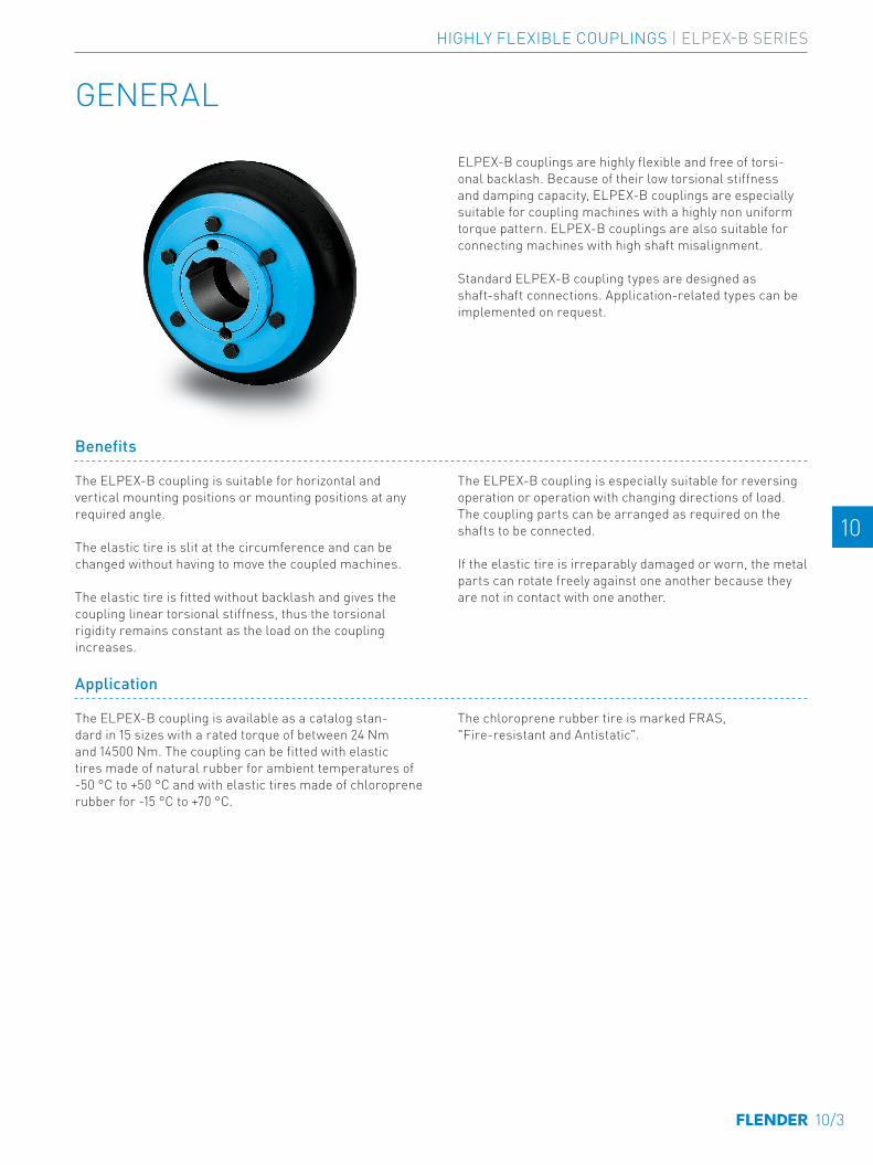
GENERAL
Benefits
The ELPEX-B coupling is suitable for horizontal and vertical mounting positions or mounting positions at any required angle.
The elastic tire is slit at the circumference and can be changed without having to move the coupled machines.
The elastic tire is fitted without backlash and gives the coupling linear torsional stiffness, thus the torsional rigidity remains constant as the load on the coupling increases.
The ELPEX-B coupling is especially suitable for reversing operation or operation with changing directions of load. The coupling parts can be arranged as required on the shafts to be connected.
If the elastic tire is irreparably damaged or worn, the metal parts can rotate freely against one another because they are not in contact with one another.
Application
The ELPEX-B coupling is available as a catalog stan-dard in 15 sizes with a rated torque of between 24 Nm and 14500 Nm. The coupling can be fitted with elastic tires made of natural rubber for ambient temperatures of -50 °C to +50 °C and with elastic tires made of chloroprene rubber for -15 °C to +70 °C.
The chloroprene rubber tire is marked FRAS, "Fire-resistant and Antistatic".
ELPEX-B couplings are highly flexible and free of torsi-onal backlash. Because of their low torsional stiffness and damping capacity, ELPEX-B couplings are especially suitable for coupling machines with a highly non uniform torque pattern. ELPEX-B couplings are also suitable for connecting machines with high shaft misalignment.
Standard ELPEX-B coupling types are designed as shaft-shaft connections. Application-related types can be implemented on request.
10/3
HIGHLY FLEXIBLE COUPLINGS | ELPEX-B SERIES
E E
4 4
5 5
6 6
7 7
8 8
9 9
10 10
11 11
12 12
13 13
A A

Design and configurations
The ELPEX-B coupling's transmission characteristic is determined essentially by the elastic tire. The elastic tire is manufactured from a natural rubber or a chloroprene rubber mixture with a multiply fabric insert. The elastic tire is fastened to the hubs with bolts and two clamping rings.
In type EBWT, the shaft-hub connection is achieved with Taper clamping bushes, in type EBWN with finish-drilled hubs and parallel keys. The type EBWZ connects the machine shafts additionally via a detachable adapter.
Metal part materials
• EN-GJL-250 grey cast iron or steel.
Elastic tire material
Material Hardness Marking Ambient temperature
Natural rubber 70 ShoreA 48 -50 ... +50 °CChloroprene rubber 70 ShoreA 068 FRAS -15 ... +70 °C
GENERAL
ELPEX-B coupling types
Type Description
EBWN Coupling as a shaft-shaft connection with drilled and grooved hubs
EBWT Coupling as a shaft-shaft connection with Taper clamping bushes
EBWZ Coupling as shaft-shaft connection with detachable adapter
Further application-specific coupling types are available; dimension sheets for and information on these are available on request.
The coupling types set up for shaft-hub connections with Taper clamping bushes are designated as follows:
• Variant A: Coupling with part 3 – part 3• Variant B: Coupling with part 4 – part 4• Variant AB: Coupling with part 3 – part 4
In the case of part 3, the Taper clamping bush is screwed in from the shaft end face side. The coupling half must be fitted before the machines to be connected are pushed together.
In the case of part 4, the Taper clamping bush is screwed in from the machine-housing side. If there is insufficient room, the Taper clamping bushes cannot be fitted from this side. Besides fitting space for the Taper clamping bush bolts, space for the fitting tool (offset screwdriver) must be taken into account.
In the case of coupling type EBWT, part 3 and part 4 can be combined as required. Furthermore, the variant with a Taper clamping bush can be combined with the finish-drilled hub.
10/4
HIGHLY FLEXIBLE COUPLINGS | ELPEX-B SERIES
E E
4 4
5 5
6 6
7 7
8 8
9 9
10 10
11 11
12 12
13 13
A A

The elastic tire can simply be slipped over the hub parts. The elastic tire is held firmly in place by fitting the clam-ping ring. The connection transmits the torque by frictional engagement.
Fitted coupling (shown without connecting shafts)
Fitted elastic tireUnfitted coupling
10/5
HIGHLY FLEXIBLE COUPLINGS | ELPEX-B SERIES
E E
4 4
5 5
6 6
7 7
8 8
9 9
10 10
11 11
12 12
13 13
A A
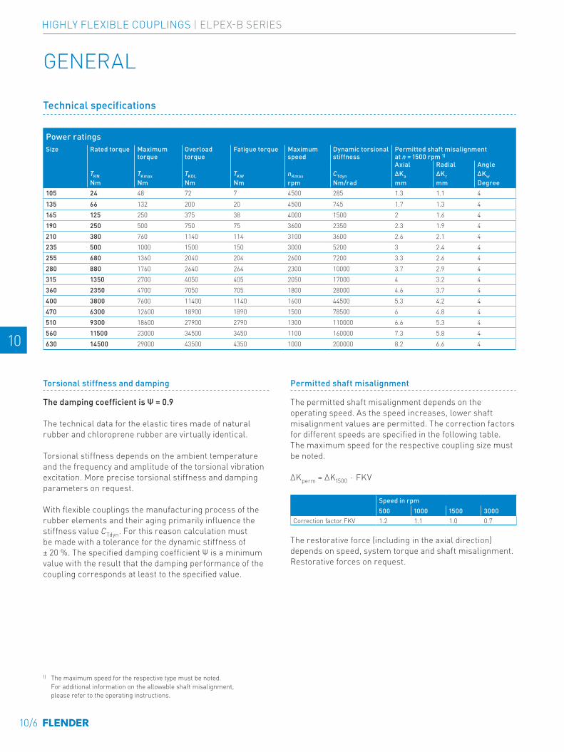
Technical specifications
Power ratingsSize Rated torque Maximum
torqueOverload torque
Fatigue torque Maximum speed
Dynamic torsional stiffness
Permitted shaft misalignment at n = 1500 rpm 1)
Axial Radial AngleTKN TKmax TKOL TKW nKmax CTdyn ΔKa ΔKr ΔKwNm Nm Nm Nm rpm Nm/rad mm mm Degree
105 24 48 72 7 4500 285 1.3 1.1 4135 66 132 200 20 4500 745 1.7 1.3 4165 125 250 375 38 4000 1500 2 1.6 4190 250 500 750 75 3600 2350 2.3 1.9 4210 380 760 1140 114 3100 3600 2.6 2.1 4235 500 1000 1500 150 3000 5200 3 2.4 4255 680 1360 2040 204 2600 7200 3.3 2.6 4280 880 1760 2640 264 2300 10000 3.7 2.9 4315 1350 2700 4050 405 2050 17000 4 3.2 4360 2350 4700 7050 705 1800 28000 4.6 3.7 4400 3800 7600 11400 1140 1600 44500 5.3 4.2 4470 6300 12600 18900 1890 1500 78500 6 4.8 4510 9300 18600 27900 2790 1300 110000 6.6 5.3 4560 11500 23000 34500 3450 1100 160000 7.3 5.8 4630 14500 29000 43500 4350 1000 200000 8.2 6.6 4
1) The maximum speed for the respective type must be noted. For additional information on the allowable shaft misalignment, please refer to the operating instructions.
Torsional stiffness and damping
The damping coefficient is Ψ = 0.9
The technical data for the elastic tires made of natural rubber and chloroprene rubber are virtually identical.
Torsional stiffness depends on the ambient temperature and the frequency and amplitude of the torsional vibration excitation. More precise torsional stiffness and damping parameters on request.
With flexible couplings the manufacturing process of the rubber elements and their aging primarily influence the stiffness value CTdyn. For this reason calculation must be made with a tolerance for the dynamic stiffness of ± 20 %. The specified damping coefficient Ψ is a minimum value with the result that the damping performance of the coupling corresponds at least to the specified value.
GENERAL
Permitted shaft misalignment
The permitted shaft misalignment depends on the operating speed. As the speed increases, lower shaft misalignment values are permitted. The correction factors for different speeds are specified in the following table. The maximum speed for the respective coupling size must be noted.
ΔKperm = ΔK1500 ⋅ FKV
Speed in rpm500 1000 1500 3000
Correction factor FKV 1.2 1.1 1.0 0.7
The restorative force (including in the axial direction) depends on speed, system torque and shaft misalignment. Restorative forces on request.
10/6
HIGHLY FLEXIBLE COUPLINGS | ELPEX-B SERIES
E E
4 4
5 5
6 6
7 7
8 8
9 9
10 10
11 11
12 12
13 13
A A
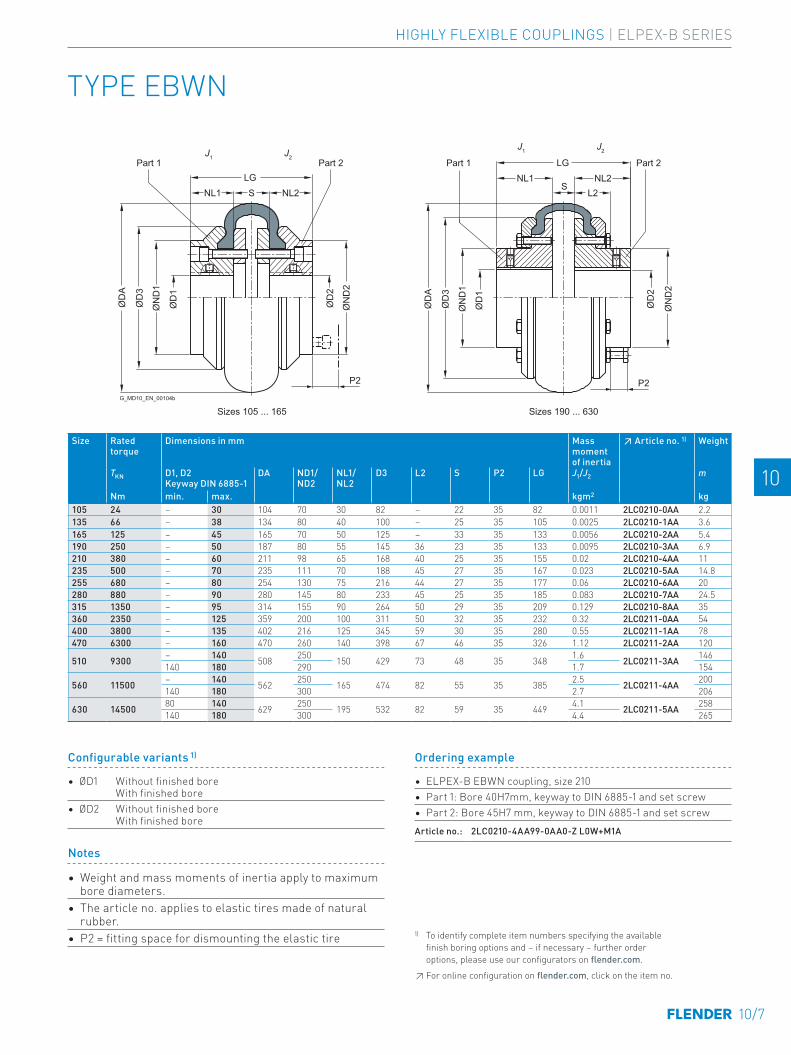
TYPE EBWN
Size Rated torque
Dimensions in mm Mass moment of inertia
↗ Article no. 1) Weight
TKN D1, D2 Keyway DIN 6885-1
DA ND1/ND2
NL1/NL2
D3 L2 S P2 LG J1/J2 m
Nm min. max. kgm2 kg105 24 – 30 104 70 30 82 – 22 35 82 0.0011 2LC0210-0AA 2.2 -0AA0135 66 – 38 134 80 40 100 – 25 35 105 0.0025 2LC0210-1AA 3.6 -0AA0165 125 – 45 165 70 50 125 – 33 35 133 0.0056 2LC0210-2AA 5.4 -0AA0190 250 – 50 187 80 55 145 36 23 35 133 0.0095 2LC0210-3AA 6.9 -0AA0210 380 – 60 211 98 65 168 40 25 35 155 0.02 2LC0210-4AA 11 -0AA0235 500 – 70 235 111 70 188 45 27 35 167 0.023 2LC0210-5AA 14.8 -0AA0255 680 – 80 254 130 75 216 44 27 35 177 0.06 2LC0210-6AA 20 -0AA0280 880 – 90 280 145 80 233 45 25 35 185 0.083 2LC0210-7AA 24.5 -0AA0315 1350 – 95 314 155 90 264 50 29 35 209 0.129 2LC0210-8AA 35 -0AA0360 2350 – 125 359 200 100 311 50 32 35 232 0.32 2LC0211-0AA 54 -0AA0400 3800 – 135 402 216 125 345 59 30 35 280 0.55 2LC0211-1AA 78 -0AA0470 6300 – 160 470 260 140 398 67 46 35 326 1.12 2LC0211-2AA 120 -0AA0
510 9300 – 140 508 250 150 429 73 48 35 348 1.6 2LC0211-3AA 146 -0AA0140 180 290 1.7 154
560 11500 – 140 562 250 165 474 82 55 35 385 2.5 2LC0211-4AA 200 -0AA0140 180 300 2.7 206
630 14500 80 140 629 250 195 532 82 59 35 449 4.1 2LC0211-5AA 258 -0AA0140 180 300 4.4 265
Part 1 Part 2 Part 2Part 1
G_MD10_EN_00104b
Sizes 105 ... 165 Sizes 190 ... 630
J1 J2
J1 J2
P2 P2
S
LGNL2NL1
S
ØD
1
ØD
A
ØD
3
ØN
D1
ØN
D2
ØD
2
ØN
D2
ØD
2
LGL2NL2NL1
ØD
1
ØD
A
ØD
3
ØN
D1
Ordering example
• ELPEX-B EBWN coupling, size 210• Part 1: Bore 40H7mm, keyway to DIN 6885-1 and set screw• Part 2: Bore 45H7 mm, keyway to DIN 6885-1 and set screwArticle no.: 2LC0210-4AA99-0AA0-Z L0W+M1A
Notes
• Weight and mass moments of inertia apply to maximum bore diameters.
• The article no. applies to elastic tires made of natural rubber.
• P2 = fitting space for dismounting the elastic tire
Configurable variants 1)
• ØD1 Without finished bore With finished bore
• ØD2 Without finished bore With finished bore
1) To identify complete item numbers specifying the available finish boring options and – if necessary – further order options, please use our configurators on flender.com.↗ For online configuration on flender.com, click on the item no.
10/7
HIGHLY FLEXIBLE COUPLINGS | ELPEX-B SERIES
E E
4 4
5 5
6 6
7 7
8 8
9 9
10 10
11 11
12 12
13 13
A A

TYPE EBWT
Sizes 105 ... 165 Sizes 190 ... 560
Part 3 Part 4Part 3 Part 4
Variant AB Variant AB
Part 3
Sizes 105 ... 165
Part 4 Part 4Part 3 Part 3 Part 4
Variant A Variant B Variant AB
Variant A Variant B Variant AB
Part 3 Part 3 Part 4 Part 3 Part 4
Sizes 190 ... 560G
_MD
10_E
N_0
0105
bPart 4
J2J1J2J1
SS NL2
P1LGNL1 NL2
P1LGNL1
ØD
1
ØD
A
ØD
3
ØN
D1
ØN
D2
ØD
2
ØN
D2
ØD
2
ØD
1
ØD
A
ØD
3
ØN
D1
P2 P2
Part 3: Screw connection for Taper clamping bush from the shaft end face side Part 4: Screw connection for Taper clamping bush from the machine-housing side
10/8
HIGHLY FLEXIBLE COUPLINGS | ELPEX-B SERIES
E E
4 4
5 5
6 6
7 7
8 8
9 9
10 10
11 11
12 12
13 13
A A

Size Rated torque
Part no.
Taper Clamping Bush
Dimensions in mm Mass moment of inertia
↗ Article no. 1) Weight
TKN Size D1, D2 Keyway DIN 6885-1
DA ND1/ND2
NL1/NL2
D3 S P1 P2 LG J1/J2 Type m
Nm min. max. kgm2 A B AB kg
105 24 3 1008 10 25 104 – 22 82 22 29 35 66 0.0009 2LC0210-0AB 2LC0210-0AC 2LC0210-0AD 1.8 -0AA04
135 66 3 1210 11 32 134 80 25 100 25 38 35 75 0.0019 2LC0210-1AB 2LC0210-1AC 2LC0210-1AD 2.4 -0AA04
165 125 3 1610 14 42 165 103 25 125 33 38 35 83 0.0049 2LC0210-2AB 2LC0210-2AC 2LC0210-2AD 4 -0AA04
190 250 3 2012 14 50 187 80 32 145 23 42 35 87 0.0085 2LC0210-3AB 2LC0210-3AC 2LC0210-3AD 5.4 -0AA04 1610 14 42 25 38
210 380 3 2517 16 60 211 98 45 168 25 48 35 115 0.017 2LC0210-4AB 2LC0210-4AC 2LC0210-4AD 8 -0AA04 2012 14 50 32 42 89
235 500 3 2517 16 60 235 108 46 188 27 48 35 119 0.019 2LC0210-5AB 2LC0210-5AC 2LC0210-5AD 12 -0AA04
255 680 3 3020 25 75 254 120 51 216 27 55 35 129 0.05 2LC0210-6AB 2LC0210-6AC 2LC0210-6AD 14 -0AA04 2517 16 60 113 45 48 117
280 880 3 3020 25 75 280 134 52 233 25 55 35 129 0.075 2LC0210-7AB 2LC0210-7AC 2LC0210-7AD 22 -0AA04
315 1350 3 3525 35 100 314 140 66 264 29 67 35 161 0.11 2LC0210-8AB 2LC0210-8AC 2LC0210-8AD 23 -0AA04 3020 25 75 51 55 131
360 2350 3 3525 35 100 359 178 65 311 32 67 35 162 0.26 2LC0211-0AB 2LC0211-0AC 2LC0211-0AD 38 -0AA04
400 3800 3 4030 40 115 402 200 77 345 30 80 35 184 0.44 2LC0211-1AB 2LC0211-1AC 2LC0211-1AD 54 -0AA04
470 6300 3 4535 55 125 470 210 89 398 46 89 35 224 0.8 2LC0211-2AB 2LC0211-2AC 2LC0211-2AD 72 -0AA04
510 9300 3 4535 55 125 508 208 89 429 48 89 35 226 1.5 2LC0211-3AB 2LC0211-3AC 2LC0211-3AD 120 -0AA04
560 11500 3 5040 70 125 562 224 102 474 55 92 35 259 2 2LC0211-4AB 2LC0211-4AC 2LC0211-4AD 120 -0AA04
Ordering example
• ELPEX-B EBWT coupling, size 210, variant AB, including Taper clamping bushes
• Part 3: with Taper clamping bush, bore 60 mm• Part 4: with Taper clamping bush, bore 40 mmArticle no.: 2LC0210-4AD99-0AA0-Z L1E+M0W
Notes
• Weights and mass moments of inertia apply to coup-lings with Taper clamping bushes with maximum bore diameter.
• The article no. applies to elastic tires made of natural rubber.
• P1 = fitting space for offset screwdriver and ejector bolt for dismounting the Taper clamping bush
• P2 = fitting space for dismounting the elastic tire.
1) To identify complete item numbers specifying the available finish boring options and – if necessary – further order options, please use our configurators on flender.com.↗ For online configuration on flender.com, click on the item no.
Configurable variants 1)
• ØD1 Without finished bore With finished bore
• ØD2 Without finished bore With finished bore
10/9
HIGHLY FLEXIBLE COUPLINGS | ELPEX-B SERIES
E E
4 4
5 5
6 6
7 7
8 8
9 9
10 10
11 11
12 12
13 13
A A

TYPE EBWZ
Part 3
Sizes 190 ... 470
Part 3 Part 6 Part 5
Variant A
Part 4 Part 3 Part 3Part 1Part 3
Sizes 105 ... 165
Part 3
Variant A Variant B Variant C
Part 4 Part 3 Part 3Part 1Part 3
Sizes 190 ... 470
Variant A Variant B Variant C
Part 3
G_MD10_EN_00106a
J2
ØD
1
ØD
A
ØD
3
ØN
D1
S1
LG
S2 LZ
S NL2NL1
ØD
4
ØN
D2
ØD
W
ØD
2
Part 3: Screw connection for Taper clamping bush from the shaft end face side Part 4: Screw connection for Taper clamping bush from the machine-housing side
10/10
HIGHLY FLEXIBLE COUPLINGS | ELPEX-B SERIES
E E
4 4
5 5
6 6
7 7
8 8
9 9
10 10
11 11
12 12
13 13
A A

Size Rated torque
Dimensions in mm Mass moment of inertia
↗ Article no. 1) Weight
TKN D1, D2 Keyway DIN 6885-1
DA ND2 D4 DW NL2 LZ S S1 S2 J2 Type m
Nm min. max. min. max. min. kgm2 A B C kg
105 24 – 42 104 70 95 25 45 96 100 116 22 6 0.0027 2LC0210-0AG 2LC0210-0AH 2LC0210-0AJ 3.3 -0A.0133 140 156
135 66 – 55 134 90 125 32 50 93 100 116 25 9 0.0085 2LC0210-1AG 2LC0210-1AH 2LC0210-1AJ 5.4 -0A.0133 140 156
165 125 – 55 165 90 125 32 50 93 100 124 33 9 0.012 2LC0210-2AG 2LC0210-2AH 2LC0210-2AJ 6.2 -0A.0133 140 164
190 250 – 75 187 125 180 48 8093.5 100 114
23 9 0.046 2LC0210-3AG 2LC0210-3AH 2LC0210-3AJ 16 -0A.0133.5 140 154173.5 180 194
210 380 – 75 211 125 180 48 80 133.5 140 156 25 9 0.053 2LC0210-4AG 2LC0210-4AH 2LC0210-4AJ 17 -0A.0173.5 180 196
235 500 – 75 235 125 180 48 80 133.5 140 158 27 9 0.056 2LC0210-5AG 2LC0210-5AH 2LC0210-5AJ 25 -0A.0173.5 180 198
255 680 – 90 254 150 225 60 100 133.5 140 158 27 9 0.15 2LC0210-6AG 2LC0210-6AH 2LC0210-6AJ 29 -0A.0173.5 180 198
280 880 – 90 280 150 225 60 100 133.5 140 156 25 9 0.17 2LC0210-7AG 2LC0210-7AH 2LC0210-7AJ 33 -0A.0173.5 180 196
315 1350 46 100 314 165 250 80 110 134.5 140 160 29 9 0.28 2LC0210-8AG 2LC0210-8AH 2LC0210-8AJ 40 -0A.0174.5 180 200
360 2350 46 100 359 165 250 80 110 134.5 140 163 32 9 0.43 2LC0211-0AG 2LC0211-0AH 2LC0211-0AJ 48 -0A.0174.5 180 203400 3800 51 110 402 180 280 90 120 223.5 230 250 30 10 0.88 2LC0211-1AG 2LC0211-1AH 2LC0211-1AJ 73 -0AE0470 6300 51 120 470 200 315 100 140 207.5 214 250 46 10 0.97 2LC0211-2AG 2LC0211-2AH 2LC0211-2AJ 104 -0AE0
Ordering example
• ELPEX-B EBWZ coupling, size 360 • variant C, for fitting length S min. = 190 mm • Part 1: Bore 65H7 mm, keyway to DIN 6885-1 and set screw • Part 5: Bore 70H7 mm, keyway to DIN 6885-1 and set screw Article no.: 2LC0211-0AJ99-0AC0-Z L1F+M1G
Notes
• Dimensions D1, ND1, NL1, J1 and fitting space for dismounting elastic tire and Taper clamping bush, see types EBWN or EBWT, Page 10/7 or Page 10/8
• The article no. applies to elastic tires made of natural rubber.
• Mass moment of inertia J2 and weight m as total of part 3, part 5 and part 6 with maximum bore diameter.
Configurable variants 1)
• ØD1 Without finished bore With finished bore
• ØD2 Without finished bore With finished bore
• S min. 100 mm 140 mm 180 mm
1) To identify complete item numbers specifying the available finish boring options and – if necessary – further order options, please use our configurators on flender.com.↗ For online configuration on flender.com, click on the item no.
10/11
HIGHLY FLEXIBLE COUPLINGS | ELPEX-B SERIES
E E
4 4
5 5
6 6
7 7
8 8
9 9
10 10
11 11
12 12
13 13
A A

Size Article No. Natural rubber Weight Chloroprene rubber WeightIdentification 048 kg Identification 068 FRAS kg
105 2LC0210-0WA00-0AA0 0.1 2LC0210-0WA00-0AA0-Z K01 0.1135 2LC0210-1WA00-0AA0 0.2 2LC0210-1WA00-0AA0-Z K01 0.2165 2LC0210-2WA00-0AA0 0.4 2LC0210-2WA00-0AA0-Z K01 0.4190 2LC0210-3WA00-0AA0 0.5 2LC0210-3WA00-0AA0-Z K01 0.5210 2LC0210-4WA00-0AA0 0.8 2LC0210-4WA00-0AA0-Z K01 0.8235 2LC0210-5WA00-0AA0 1 2LC0210-5WA00-0AA0-Z K01 1255 2LC0210-6WA00-0AA0 1.2 2LC0210-6WA00-0AA0-Z K01 1.2280 2LC0210-7WA00-0AA0 1.4 2LC0210-7WA00-0AA0-Z K01 1.4315 2LC0210-8WA00-0AA0 2.6 2LC0210-8WA00-0AA0-Z K01 2.6360 2LC0211-0WA00-0AA0 2.9 2LC0211-0WA00-0AA0-Z K01 2.9400 2LC0211-1WA00-0AA0 3.1 2LC0211-1WA00-0AA0-Z K01 3.1470 2LC0211-2WA00-0AA0 5.3 2LC0211-2WA00-0AA0-Z K01 5.3510 2LC0211-3WA00-0AA0 7.8 2LC0211-3WA00-0AA0-Z K01 7.8560 2LC0211-4WA00-0AA0 10.8 2LC0211-4WA00-0AA0-Z K01 10.8630 2LC0211-5WA00-0AA0 12.4 2LC0211-5WA00-0AA0-Z K01 12.4
Note
• The elastic tires are wear parts. The service life depends on the operating conditions.
SPARE AND WEAR PARTS
Elastic tire
10/12
HIGHLY FLEXIBLE COUPLINGS | ELPEX-B SERIES
E E
4 4
5 5
6 6
7 7
8 8
9 9
10 10
11 11
12 12
13 13
A A
10/13
HIGHLY FLEXIBLE COUPLINGS | ELPEX-B SERIES
E E
4 4
5 5
6 6
7 7
8 8
9 9
10 10
11 11
12 12
13 13
A A

10/14

HIGHLY FLEXIBLE COUPLINGS – ELPEX-S SERIES
ELPEX-S
01-Einzelschilder-03-2020.indd 8 09.03.20 14:00
General 11/3Benefits 11/3Application 11/3Design and configurations 11/4Function 11/6Configuration 11/6Technical specifications 11/8
Type ESN 11/14
Type ESNR 11/16
Type ESD 11/18
Type ESDR 11/19
Type ESNW 11/20
Type ESDW 11/21
Type EST 11/22
Spare and wear parts 11/23
11/1
E E
4 4
5 5
6 6
7 7
8 8
9 9
10 10
11 11
12 12
13 13
A A
HIGHLY FLEXIBLE COUPLINGS | ELPEX-S SERIES

11/2
E E
4 4
5 5
6 6
7 7
8 8
9 9
10 10
11 11
12 12
13 13
A A
HIGHLY FLEXIBLE COUPLINGS | ELPEX-S SERIES

GENERAL
Coupling suitable for use in potentially explosive atmospheres. Complies with the current ATEX Directive for:
II 2G Ex h IIC T4 ... T3 Gb X
II 2D Ex h IIIC T120 °C ... 160 °C Db X
I M2 Ex h Mb X
(Type EST is not available in Ex version.)ELPEX-S couplings are highly torsionally flexible and because of their low torsional stiffness and damping capacity are especially suitable for coupling machines with a highly non uniform torque pattern. Standard ELPEX-S coupling types are designed as flange-shaft-connections or shaft-shaft connections. Application-related types can be implemented on request.
Benefits
The ELPEX-S coupling is suitable for horizontal and vertical mounting positions or mounting at any required angle. The coupling parts can be arranged as required on the shafts to be connected.
ELPEX-S couplings are especially suitable for reversing operation or operation with changing directions of load.
The rubber disk elements are fitted virtually without backlash and give the coupling linear torsional stiffness, i.e. the torsion stiffness remains constant even when the load on the coupling increases.
There are 4 different rubber element versions with diffe-rent grades of torsional stiffness available for each size from stock.
On certain types the flexible rings can be changed without having to move the coupled machines.
If substantial overload occurs, the rubber disk element of the coupling is irreparably damaged, the coupling throws the load and thus limits the overload for particular opera-ting conditions. The coupling can be inserted and fitted blind e.g. in a bell housing.
There are outer flanges with different connection dimensions available for each coupling size.
Application
The ELPEX-S coupling is available as a catalog standard in 12 sizes with rated torques of between 330 Nm and 63000 Nm.
The coupling is suitable for ambient temperatures of between -40 °C and +120 °C.
The ELPEX-S coupling is frequently used for diesel motor drives or reciprocating compressor drives.
Because the different rubber versions enable the torsi-onal stiffness to be adjusted to meet requirements, the coupling is also suitable for drives which require a specific and preferably precalculated torsional vibration behavior setting.
11/3
E E
4 4
5 5
6 6
7 7
8 8
9 9
10 10
11 11
12 12
13 13
A A
HIGHLY FLEXIBLE COUPLINGS | ELPEX-S SERIES

Design and configurations
The rubber disk element is vulcanized onto a flange on the inside diameter. The flange can mount e.g. a Taper clam-ping bush or a hub. On its outer diameter the rubber disk element has driving teeth, which are inserted into the outer flange. The torque is transmitted positively between the rubber disk element and the outer flange.
In the type for shaft-shaft connection the outer flange is screwed to a flange hub mounted on a machine shaft.
GENERAL
Elastomer materials of the rubber disk element
Material/ description
Hardness ShoreA
Marking Ambient temperature
Natural-synthetic rubber mixture
50 ° … 55 ° WN -40 °C … +80 °C60 ° … 65 ° NN -40 °C … +80 °C70 ° … 75 ° SN -40 °C … +80 °C
Silicone rubber 55 ° … 65 ° NX -40 °C … +120 °C
ELPEX-S coupling types
Type DescriptionESN Coupling with hub, long or short versionESD Coupling with hub, with two rubber disk elementsESNR Coupling with hub, rubber disk element radially dismountable
ESDR Coupling with hub with two rubber disk elements; rubber disk elements radially dismountable
ESNW Coupling designed as a shaft-shaft connection with a rubber disk element; rubber disk element radially dismountable
ESDWCoupling designed as a shaft-shaft connection with two rubber disk elements; rubber disk element radially dismountable
EST Coupling suitable for mounting a Taper clamping bush
The following versions have already been implemented a number of times:
• ELPEX-S coupling with brake drum, brake disk or flywheel mass
• ELPEX-S coupling with axial backlash limiter• ELPEX-S coupling with adapter• ELPEX-S coupling with bearing for mounting a cardan
shaft• ELPEX-S coupling for engaging/disengaging during
standstill• ELPEX-S coupling as part of a coupling combination• ELPEX-S coupling with fail-safe device
Materials
Type EST Types ESN. and ESD.Rubber disk element EN-GJL-250
grey cast iron/ elastomer
EN-GJL-400 spheroidal graphite cast iron/elastomer
Hubs, part 1, part 2 Steel SteelOuter flange Cast aluminum
Zn10Si8Mg Sizes 680 and 770 of spheroidal graphite cast iron EN-GJS-500
Cast aluminum Zn10Si8Mg Sizes 680 and 770 of spheroidal graphite cast iron EN-GJS-500
Further application-related coupling types are available. Dimension sheets for and information on these are available on request.
11/4
E E
4 4
5 5
6 6
7 7
8 8
9 9
10 10
11 11
12 12
13 13
A A
HIGHLY FLEXIBLE COUPLINGS | ELPEX-S SERIES

Part 3 Part 5 Part 2
G_M
D10
_EN
_000
56
Part 5 Part 3 Part 5 Part 2
G_M
D10
_EN
_000
19
G_M
D10
_EN
_000
16
Part 3 Part 5 Part 2 Part 6 Part 3 Part 5 Part 2
G_M
D10
_EN
_000
20
Part 3 Part 6 Part 2
G_M
D10
_DE
_000
17
Part 3Part 1 Part 6 Part 2
G_M
D10
_EN
_000
21
Part 3 Part 5
G_M
D10
_EN
_000
18
Part 6 Part 3 Part 5 Part 2Part 1
G_M
D10
_EN
_000
22
Type ESN – long version Type ESD
Type ESN – short version Type ESDR
Type ESNR Type ESNW
Type EST Type ESDW
11/5
E E
4 4
5 5
6 6
7 7
8 8
9 9
10 10
11 11
12 12
13 13
A A
HIGHLY FLEXIBLE COUPLINGS | ELPEX-S SERIES

GENERAL
Configuration
Coupling selection
The ELPEX-S coupling is especially suitable for rough operating environments. An application factor lower than that in the chapter introduction is therefore sufficient for all applications.
In the case of machines which excite torsional vibration, Flender urgently recommends carrying out a torsional vibration calculation or measuring the coupling load occurring in the drive.
Coupling load in continuous operation
Application factor FBTorque characteristic of the driven machineuniform with moderate shock loads
non uniform very rough
Electric motors, hydraulic motors, gas and water turbines
1.0 1.3 1.4
Internal-combustion engines 1.3 1.4 1.6
Examples of torque characteristic in driven machines:• uniform with moderate shock loads: Generators,
fans, blowers • non uniform: Reciprocating compressors, mixers,
conveyor systems• very rough: crushers, excavators, presses, mills
Temperature factor FTTemperature Ta on the coupling
Coupling Rubber version
Elastomer material
-40 up to -30 °C
-30 up to +50 °C
up to 60 °C
up to 70 °C
up to 80 °C
up to 90 °C
up to 100 °C
up to 110 °C
up to 120 °C
ELPEX-SSN, NN, WN NR 1.1 1.0 1.25 1.40 1.60 – – – –NX VMQ 1.1 1.0 1.0 1.0 1.0 1.1 1.25 1.4 1.6
NR = Natural-synthetic rubber mixtureVMQ = Silicone rubber
Coupling size TKN ≥ TN ⋅ FB ⋅ FT
Function
The ELPEX-S coupling's transmission characteristic is determined essentially by the rubber disk element. The torque is transmitted positively between the rubber disk element and the outer flange.
The outer flange can be bolted to e.g. a diesel motor or compressor flywheel.
Fail-safe device of ELPEX-S coupling
The ELPEX-S coupling can also be designed with a fail-safe device. If the rubber disk element fails, the coupling can continue operating in emergency mode for a short time. This option is frequently required e.g. in the case of marine drives.
If the rubber disk element fails, cams transmit the torque from the inner and outer parts of the fail-safe device.
In normal operation the torsion angle of the rubber disk element is smaller than the gap between the cams, so there is no metal-metal contact.
G_M
D10
_XX
_000
23
11/6
E E
4 4
5 5
6 6
7 7
8 8
9 9
10 10
11 11
12 12
13 13
A A
HIGHLY FLEXIBLE COUPLINGS | ELPEX-S SERIES
Coupling load under maximum and overload conditions
The maximum torque is the highest load acting on the coupling in normal operation. Maximum torques at a frequency of up to 25 times an hour are permitted and must be lower than the maximum coupling torque. Examples of maximum torque conditions are: Starting operations, stopping operations or usual operating conditions with maximum load.
TKmax ≥ TMax ⋅ FT
Overload torques are maximum loads which occur only in combination with special, infrequent operating conditions. Examples of overload torque conditions are: Motor short circuit, emergency stop or blocking because of component breakage. Overload torques at a frequency of once a month are permitted and must be lower than the maximum over-load torque of the coupling. The overload condition may last only a short while, i.e. fractions of a second.
TKOL ≥ TOL ⋅ FT
Coupling load due to dynamic torque load
Applying the frequency factor FF, the dynamic torque load must be lower than the coupling fatigue torque.
Dynamic torque load
TKW ≥ TW ⋅ FF ⋅ FF
Frequency of the dynamic torque load ferr ≤ 10 Hz frequency factor FF = 1.0
Frequency of the dynamic torque load ferr > 10 Hz frequency factor FF = √(ferr/10 Hz)
Operation in potentially explosive environments is subject to the following restriction:Operation with low fatigue loadThe fatigue torque TKW must be reduced by 70 %. In these particular operating conditions the coupling satisfies the requirements of temperature class T4 D120 °C.Operation with medium fatigue loadThe fatigue torque TKW must be reduced by 50 %. In these particular operating conditions the coupling satisfies the requirements of temperature class T3 D160 °C.Type EST is not permitted for application in potentially explosive environments.
Checking the maximum speed
The following must apply to all load situations: nKmax ≥ nmaxThe maximum speed of a size depends only on the size of the outer flange (part 3).
Checking permitted shaft misalignment and restorative forces
For all load situations, the actual shaft misalignment must be less than the permitted shaft misalignment.
Checking bore diameter, mounting geometry and coupling design
The check must be made on the basis of the dimension tables. On request, couplings with adapted geometry can be provided.
Checking shaft-hub connection
For any information on this, please refer to Page E/18.
Checking temperature and chemically aggressive environment
The permitted coupling temperature is specified in the Temperature Factor FT table. In the case of chemically aggressive environments, please consult the manufac-turer.
11/7
E E
4 4
5 5
6 6
7 7
8 8
9 9
10 10
11 11
12 12
13 13
A A
HIGHLY FLEXIBLE COUPLINGS | ELPEX-S SERIES

GENERAL
Performance data for rubber disk elements made of a mix of natural and synthetic rubberType Size Rubber
versionRated torque Maximum
torqueOverload torque
Fatigue torque dynamic torsio-nal stiffness
Motor flange SAE J620d
Maximum speed
TKN TKmax TKOL TKW CTdyn Size nmax
Nm Nm Nm Nm Nm/rad rpm
ESN . EST 220
WN 330 660 750 165 1600 6.5 4200NN 360 720 900 180 2500 7.5 4200
SN 400 800 1000 200 42008 420010 3600
ESN . EST 265
WN 500 1000 1250 250 2400 8 4200NN 600 1200 1800 300 3600 10 3600SN 700 1400 2100 350 6100 11.5 3500
ESN . EST 290
WN 800 1600 2000 400 3600 10 3600NN 900 1800 2700 450 5000
11.5 3500SN 1000 2000 3000 500 7500
ESN . EST 320
WN 1200 2400 3000 600 8000 11.5 3500NN 1350 2700 3600 650 10000
14 3000SN 1550 3100 4200 750 13500
ESN . EST 360
WN 1800 3600 4500 900 8500 11.5 3200NN 2000 4000 5400 1000 13000
14 3000SN 2500 5000 7500 1250 22000
ESN . EST 420
WN 3100 6200 7700 1500 16000 14 3000NN 3450 6900 10000 1700 30000 16 2600SN 4200 8400 12600 2100 45000 18 2300
ESN . EST 465
WN 4600 9200 10000 2300 35000 14 3000NN 5200 10400 15600 2600 56000 16 2600SN 6300 12600 18900 3100 100000 18 2300
ESN . 520WN 6200 12400 14000 3100 38000 18 2300NN 7000 14000 21000 3500 75000
21 2000SN 7800 15600 23400 3900 110000
ESD . 520WN 12400 24800 28000 6200 76000 18 2300NN 14000 28000 42000 7000 150000
21 2000SN 15600 31200 46800 7800 220000
ESN . 560WN 8000 16000 18000 4200 55000 18 2300NN 9000 18000 27000 4800 100000
21 2000SN 10000 20000 30000 5500 190000
ESD . 560WN 16000 32000 36000 8400 110000 18 2300NN 18000 36000 54000 9600 200000
21 2000SN 20000 40000 60000 11000 380000
Technical specifications
11/8
E E
4 4
5 5
6 6
7 7
8 8
9 9
10 10
11 11
12 12
13 13
A A
HIGHLY FLEXIBLE COUPLINGS | ELPEX-S SERIES

Torsional stiffness and damping
Torsional stiffness depends on the ambient temperature and the frequency and amplitude of the torsional vibration excitation. More precise torsional stiffness and damping parameters on request.
With flexible couplings the manufacturing process of the rubber elements and their aging primarily influence the stiffness value CTdyn.
For this reason calculation must be made with a tolerance for the dynamic stiffness of ± 20 %. The specified damping coefficient Ψ is a minimum value with the result that the damping performance of the coupling corresponds at least to the specified value.
Performance data for rubber disk elements made of a mix of natural and synthetic rubberType Size Rubber
versionRated torque Maximum
torqueOverload torque
Fatigue torque dynamic torsio-nal stiffness
Motor flange SAE J620d
Maximum speed
TKN TKmax TKOL TKW CTdyn Size max
Nm Nm Nm Nm Nm/rad rpm
ESN . 580WN 11000 22000 28000 5500 75000 18 2300NN 12500 25000 37000 6250 120000
21 2000SN 14000 28000 42000 7000 210000
ESD . 580WN 22000 44000 56000 11000 150000 21 2000NN 25000 50000 74000 12500 240000
24 1800SN 28000 56000 84000 14000 420000
ESN . 680WN 16000 32000 40000 8000 150000 21 2000NN 18000 36000 54000 9000 250000
24 1800SN 20000 40000 60000 10000 450000
ESD . 680WN 32000 64000 80000 16000 300000 21 2000NN 36000 72000 108000 18000 500000
24 1800SN 40000 80000 120000 20000 900000
ESN . 770WN 25000 50000 75000 12500 250000
similar to DIN 6288 1500NN 28000 56000 84000 14000 400000
SN 31500 63000 94000 15000 700000
ESD . 770WN 50000 100000 150000 25000 500000
similar to DIN 6288 1300NN 56000 112000 168000 28000 800000
SN 63000 126000 189000 30000 1400000
11/9
E E
4 4
5 5
6 6
7 7
8 8
9 9
10 10
11 11
12 12
13 13
A A
HIGHLY FLEXIBLE COUPLINGS | ELPEX-S SERIES

GENERAL
Load TN / TKN20% 50% 60% 70% 80% 100% 150%
Correction factor FKC 0.59 0.75 0.79 0.83 0.88 1 1.5
Power ratings of the rubber disk elements made of silicone rubberType Size Rubber
versionRated torque Maximum torque Overload torque Fatigue torque Dynamic torsional
stiffness for 100 % load
TKN TKmax TKOL TKW (10 Hz) CTdyn
Nm Nm Nm Nm Nm/radESN . 220 NX 200 300 400 87 1.3ESN . 265 NX 300 450 600 133 2.4ESN . 290 NX 500 750 1000 213 4.2ESN . 320 NX 770 1150 1530 320 9.2ESN . 360 NX 1200 1800 2400 480 10ESN . 420 NX 2000 3000 4000 800 23ESN . 465 NX 3000 4500 6000 1200 60ESN . 520 NX 4100 6100 8200 1600 65ESD . 520 NX 8200 12300 16400 3200 130ESN . 560 NX 5000 7500 10000 2200 100ESD . 560 NX 10000 15000 20000 4400 200ESN . 580 NX 6500 9750 13000 2667 160ESD . 580 NX 13000 19500 26000 5867 310ESN . 680 NX 10000 15000 20000 4000 280ESD . 680 NX 20000 30000 40000 8000 550ESN . 770 NX 15000 22500 30000 6000 620ESD . 770 NX 30000 45000 60000 12000 1230
Torsional stiffness
The dynamic torsional stiffness of the silicone rubber elements is load-dependent and increases in propor-tion to the load. The values specified in the selection table represent 100 % loading. The following table shows the correction factors for different rated loads.
CTdyn = CTdyn 100 % ⋅ FKC
Torsional stiffness also depends on the ambient tempe-rature and the frequency and amplitude of the torsional vibration excitation. More precise torsional stiffness and damping parameters on request.
Technical specifications
11/10
E E
4 4
5 5
6 6
7 7
8 8
9 9
10 10
11 11
12 12
13 13
A A
HIGHLY FLEXIBLE COUPLINGS | ELPEX-S SERIES

With flexible couplings the manufacturing process of the rubber elements and their aging primarily influence the stiffness value CTdyn. For this reason calculation must be made with a tolerance for the dynamic stiffness of ± 20 %. The specified damping coefficient Ψ is a minimum value with the result that the damping performance of the coupling corresponds at least to the specified value.
Damping coefficient of the rubber versionsRubber version Hardness ShoreA Damping coefficient
ΨWN 55 ° ± 5 ° 0.80NN 65 ° ± 5 ° 1.15SN 75 ° ± 5 ° 1.25NX 60 ° ± 5 ° 1.15
Permitted shaft misalignment
The permitted shaft misalignment depends on the operating speed. As the speed increases, lower shaft misalignment values are permitted.
For fitting, the maximum gap dimension of S max. = S + ΔS and the minimum gap dimension of S min. = S – ΔS are permitted.
Damping coefficient
Size Assembly Permitted shaft misalignment at n = 1500 rpmShaft distance Axial Radial Angle∆S ∆Ka ∆Kr ∆Kwmm mm mm degree
220 1.3 0.2 1.2 0.5265 1.3 0.2 1.2 0.5290 1.5 0.2 1.2 0.5320 1.5 0.2 1.2 0.5360 1.5 0.2 1.2 0.5420 1.5 0.3 1.3 0.4465 1.7 0.3 1.3 0.4520 1.7 0.3 1.4 0.4560 1.7 0.3 1.4 0.4580 1.8 0.4 1.5 0.3680 1.8 0.4 1.5 0.3770 2.0 0.5 1.5 0.3
The correction factors for different speeds are specified in the following table.
The maximum speed for the respective coupling size and type must be noted!
∆Kperm = ∆K1500 ⋅ FKV
Speed in rpm500 1000 1500 3000
Correction factor FKV 1.2 1.1 1.0 0.7
11/11
E E
4 4
5 5
6 6
7 7
8 8
9 9
10 10
11 11
12 12
13 13
A A
HIGHLY FLEXIBLE COUPLINGS | ELPEX-S SERIES

GENERAL
Variants of the outer flange
The outer flange of sizes 220 to 680 is designed to fit the connection dimensions of the SAE J620d standard. The centering depth on the connection flange of the machine should be between 4 mm and 6.4 mm maximum.
Type Size Flange connection size FigureESN 220 6.5 1ESN 220 7.5
2ESN, ESNR
265 8360 11.5465 14580 18680 21
ESN 220 8, 10
3ESN, ESNR
265 10, 11.5290 all320 all360 14420 all465 16, 18520 all560 all580 21680 24
ESNR 770 all
ESD, ESDR520 all
4560 all580 all
ESD, ESDR 680 21 5ESD, ESDR 680 24
6ESDR 770 all
G_M
D10
_XX
_000
24
G_M
D10
_XX
_000
25a
Figure 1 Figure 2
G_M
D10
_XX
_000
26
G_M
D10
_XX
_000
27
Figure 3 Figure 4
G_M
D10
_XX
_000
28
G_M
D10
_XX
_000
29
Figure 5 Figure 6
11/12
E E
4 4
5 5
6 6
7 7
8 8
9 9
10 10
11 11
12 12
13 13
A A
HIGHLY FLEXIBLE COUPLINGS | ELPEX-S SERIES

11/13
E E
4 4
5 5
6 6
7 7
8 8
9 9
10 10
11 11
12 12
13 13
A A
HIGHLY FLEXIBLE COUPLINGS | ELPEX-S SERIES

TYPE ESN
Size Dimensions in mm Mass moment of inertia
↗ Article no. 1) Weight
Flange connection dimensionsD2 Keyway DIN 6885
DA ND2 NL2 short version
long version SAE size
DFA DFK FB ZF DFB J1 J2 Type m
A LG A S LG short version long versionmax. g7 kgm2 kgm2 kg
220 60
222
98 54 - - 0
49 103 6.5 215.9 200.0 6 6 8.5 0.008
0.01
– 2LC0220-0AB0 5.8 .-.AA0237 40 94 7.5 241.3 222.3 33 8 8.5 0.011 – 2LC0220-0AB0 6.1 .-.BA0222 40 94 8 263.5 244.5 8 6 10.5 0.011 – 2LC0220-0AB0 6.4 .-.CA0222 40 94 10 314.3 295.3 8 8 10.5 0.017 – 2LC0220-0AB0 6.9 .-.DA0
265 65 263 118 65 15 74 3 39 1048 263.5 244.5 33 6
10.50.011
0.0222LC0220-1AA0 2LC0220-1AB0 6.6 .-.CA0
10 314.3 295.3 10 8 0.017 2LC0220-1AA0 2LC0220-1AB0 6.9 .-.DA011.5 352.4 333.4 10 8 0.024 2LC0220-1AA0 2LC0220-1AB0 7.2 .-.EA0
290 65 290 118 70 18 58 6 36 106 10 314.3 295.3 16 8 10.5 0.026 0.026 2LC0220-2AA0 2LC0220-2AB0 9.2 .-.DA011.5 352.4 333.4 16 8 0.036 2LC0220-2AA0 2LC0220-2AB0 10.5 .-.EA0
320 80 318 140 87 15 96 2 70 157 11.5 352.4 333.4 16 8 10.5 0.062 0.061 2LC0220-3AA0 2LC0220-3AB0 19 .-.EA014 466.7 438.2 16 8 13 0.18 2LC0220-3AA0 2LC0220-3AB0 20.5 .-.FA0
360 90 353.5 160 105 29 92 13 56 161 11.5 352.4 333.4 54 8 10.5 0.065 0.13 2LC0220-4AA0 2LC0220-4AB0 24.5 .-.EA014 466.7 438.2 15 8 13 0.18 2LC0220-4AA0 2LC0220-4AB0 27.5 .-.FA0
420 100 420 185 102 26 92 10 72 17414 466.7 438.2 18 8 13 0.22
0.322LC0220-5AA0 2LC0220-5AB0 36 .-.FA0
16 517.5 489.0 18 8 13 0.32 2LC0220-5AA0 2LC0220-5AB0 38 .-.GA018 571.5 542.9 18 6 17 0.47 2LC0220-5AA0 2LC0220-5AB0 40 .-.HA0
Configurable variants 1)
• ØD2 Without finished bore With finished bore
• Rubber version WN NN SN NX
1) To identify complete item numbers specifying the available finish boring options and – if necessary – further order options, please use our configurators on flender.com.
A LG
short versionVariant G
_MD
10_E
N_0
0031
Short version
1J 2J
ZF x ØDFB
ØD
FAØ
DFK
ØD
2
ØD
AØ
ND
2
FBA LG
NL2S
Part 3 Part 5 Part 2
long versionVariant
G_MD10_EN_00030
Long version
↗ For online configuration on flender.com, click on the item no.
11/14
E E
4 4
5 5
6 6
7 7
8 8
9 9
10 10
11 11
12 12
13 13
A A
HIGHLY FLEXIBLE COUPLINGS | ELPEX-S SERIES

Notes
• The rubber disk element cannot be dismounted until the machines have been moved.
• Weight and mass moments of inertia apply to maximum bore diameters.
Ordering example
• ELPEX-S ESN coupling, size 520, WN rubber element version
• Bore ØD2 = 150H7 mm, with keyway to DIN 6885 and set screw, outer flange to SAE J620d size 21
Short version article no.: 2LC0220-7AA09-1JA0-Z M1WLong version article no.: 2LC0220-7AB09-1JA0-Z M1W
Configurable variants 1)
• ØD2 Without finished bore With finished bore
• Rubber version WN NN SN NX
1) To identify complete item numbers specifying the available finish boring options and – if necessary – further order options, please use our configurators on flender.com.↗ For online configuration on flender.com, click on the item no.
Size Dimensions in mm Mass moment of inertia
↗ Article no. 1) Weight
Flange connection dimensionsD2 Keyway DIN 6885
DA ND2 NL2 short version
long version SAE size
DFA DFK FB ZF DFB J1 J2 Type m
A LG A S LG short version long versionmax. g7 kgm2 kgm2 kg
465 120 465 222 125 33 92 2 39 16414 466.7 438.2 85 8 13 0.31
0.582LC0220-6AA0 2LC0220-6AB0 56 .-.FA0
16 517.5 489.0 27 8 13 0.41 2LC0220-6AA0 2LC0220-6AB0 57 .-.GA018 571.5 542.9 18 6 17 0.52 2LC0220-6AA0 2LC0220-6AB0 61 .-.HA0
520 165 514 250 142 16 159 0 83 225 18 571.5 542.9 18 12 17 0.48 0.93 2LC0220-7AA0 2LC0220-7AB0 55 .-.HA021 673.1 641.4 18 12 0.95 2LC0220-7AA0 2LC0220-7AB0 60 .-.JA0
560 200 560 320 140 30 130 2.5 83 223 18 571.5 542.9 35 12 17 0.85 1.2 2LC0220-8AA0 2LC0220-8AB0 69 .-.HA021 673.1 641.4 20 12 1.8 2LC0220-8AA0 2LC0220-8AB0 78 .-.JA0
580 200 580 316 200 23 215 0 100 300 18 571.5 542.9 104 12 17 0.77 1.8 2LC0221-0AA0 2LC0221-0AB0 100 .-.HA021 673.1 641.4 26 12 1.2 2LC0221-0AA0 2LC0221-0AB0 105 .-.JA0
680 220 682 380 210 24 232 0 102 312 21 673.1 641.4 85 12 17 4.1 5.3 2LC0221-1AA0 2LC0221-1AB0 205 .-.JA024 733.4 692.2 20 12 21 5.3 2LC0221-1AA0 2LC0221-1AB0 215 .-.KA0
11/15
E E
4 4
5 5
6 6
7 7
8 8
9 9
10 10
11 11
12 12
13 13
A A
HIGHLY FLEXIBLE COUPLINGS | ELPEX-S SERIES
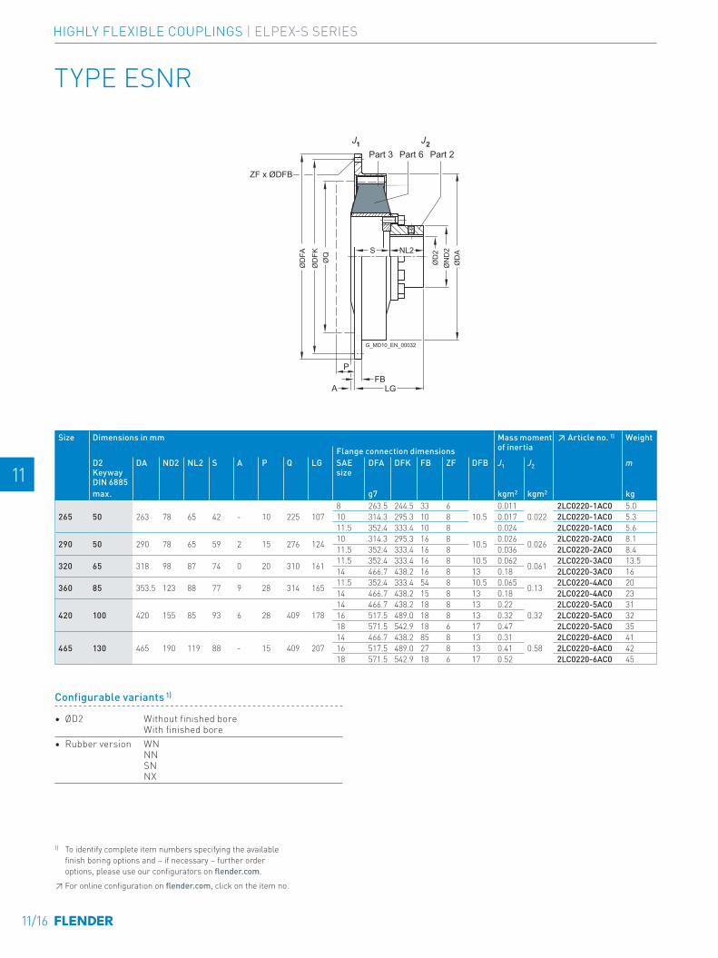
TYPE ESNR
1J 2J
ZF x ØDFB
ØD
2
ØD
AØ
ND
2S NL2
A
P
LGFB
ØD
FA
ØD
FKØ
Q
1 2Part 3 Part 6 Part 2
G_MD10_EN_00032
Size Dimensions in mm Mass moment of inertia
↗ Article no. 1) WeightFlange connection dimensions
D2 Keyway DIN 6885
DA ND2 NL2 S A P Q LG SAE size
DFA DFK FB ZF DFB J1 J2 m
max. g7 kgm2 kgm2 kg
265 50 263 78 65 42 - 10 225 1078 263.5 244.5 33 6
10.50.011
0.0222LC0220-1AC0 5.0 .-.CA0
10 314.3 295.3 10 8 0.017 2LC0220-1AC0 5.3 .-.DA011.5 352.4 333.4 10 8 0.024 2LC0220-1AC0 5.6 .-.EA0
290 50 290 78 65 59 2 15 276 124 10 314.3 295.3 16 8 10.5 0.026 0.026 2LC0220-2AC0 8.1 .-.DA011.5 352.4 333.4 16 8 0.036 2LC0220-2AC0 8.4 .-.EA0
320 65 318 98 87 74 0 20 310 161 11.5 352.4 333.4 16 8 10.5 0.062 0.061 2LC0220-3AC0 13.5 .-.EA014 466.7 438.2 16 8 13 0.18 2LC0220-3AC0 16 .-.FA0
360 85 353.5 123 88 77 9 28 314 165 11.5 352.4 333.4 54 8 10.5 0.065 0.13 2LC0220-4AC0 20 .-.EA014 466.7 438.2 15 8 13 0.18 2LC0220-4AC0 23 .-.FA0
420 100 420 155 85 93 6 28 409 17814 466.7 438.2 18 8 13 0.22
0.322LC0220-5AC0 31 .-.FA0
16 517.5 489.0 18 8 13 0.32 2LC0220-5AC0 32 .-.GA018 571.5 542.9 18 6 17 0.47 2LC0220-5AC0 35 .-.HA0
465 130 465 190 119 88 - 15 409 20714 466.7 438.2 85 8 13 0.31
0.582LC0220-6AC0 41 .-.FA0
16 517.5 489.0 27 8 13 0.41 2LC0220-6AC0 42 .-.GA018 571.5 542.9 18 6 17 0.52 2LC0220-6AC0 45 .-.HA0
1) To identify complete item numbers specifying the available finish boring options and – if necessary – further order options, please use our configurators on flender.com.↗ For online configuration on flender.com, click on the item no.
Configurable variants 1)
• ØD2 Without finished bore With finished bore
• Rubber version WN NN SN NX
11/16
E E
4 4
5 5
6 6
7 7
8 8
9 9
10 10
11 11
12 12
13 13
A A
HIGHLY FLEXIBLE COUPLINGS | ELPEX-S SERIES
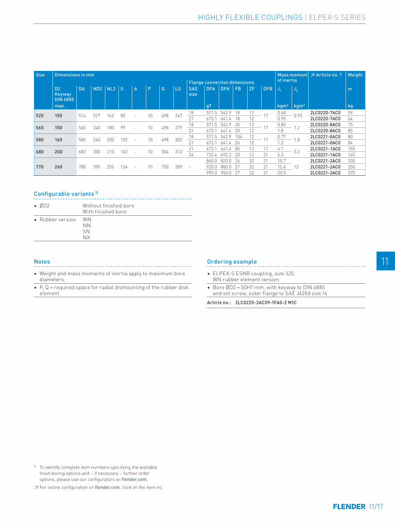
Notes
• Weight and mass moments of inertia apply to maximum bore diameters.
• P, Q = required space for radial dismounting of the rubber disk element.
Ordering example
• ELPEX-S ESNR coupling, size 320, WN rubber element version
• Bore ØD2 = 50H7 mm, with keyway to DIN 6885 and set screw, outer flange to SAE J620d size 14
Article no.: 2LC0220-3AC09-1FA0-Z M1C
1) To identify complete item numbers specifying the available finish boring options and – if necessary – further order options, please use our configurators on flender.com.↗ For online configuration on flender.com, click on the item no.
Configurable variants 1)
• ØD2 Without finished bore With finished bore
• Rubber version WN NN SN NX
Size Dimensions in mm Mass moment of inertia
↗ Article no. 1) WeightFlange connection dimensions
D2 Keyway DIN 6885
DA ND2 NL2 S A P Q LG SAE size
DFA DFK FB ZF DFB J1 J2 m
max. g7 kgm2 kgm2 kg
520 150 514 227 162 85 - 10 498 247 18 571.5 542.9 18 12 17 0.48 0.93 2LC0220-7AC0 59 .-.HA021 673.1 641.4 18 12 0.95 2LC0220-7AC0 64 .-.JA0
560 150 560 240 180 99 - 10 498 279 18 571.5 542.9 35 12 17 0.85 1.2 2LC0220-8AC0 75 .-.HA021 673.1 641.4 20 12 1.8 2LC0220-8AC0 85 .-.JA0
580 160 580 240 200 102 - 10 498 302 18 571.5 542.9 104 12 17 0.77 1.8 2LC0221-0AC0 80 .-.HA021 673.1 641.4 26 12 1.2 2LC0221-0AC0 84 .-.JA0
680 200 682 300 210 102 - 10 584 312 21 673.1 641.4 85 12 17 4.1 5.3 2LC0221-1AC0 155 .-.JA024 733.4 692.2 20 12 21 5.3 2LC0221-1AC0 165 .-.KA0
770 260 780 390 255 134 - 10 750 389 -860.0 820.0 26 32 21 10.7
122LC0221-2AC0 330 .-.LA0
920.0 880.0 27 32 21 15.4 2LC0221-2AC0 350 .-.MA0995.0 950.0 27 32 21 20.5 2LC0221-2AC0 375 .-.NA0
11/17
E E
4 4
5 5
6 6
7 7
8 8
9 9
10 10
11 11
12 12
13 13
A A
HIGHLY FLEXIBLE COUPLINGS | ELPEX-S SERIES

TYPE ESD
ZF x ØDFB
ØD
2
ØD
A
ØD
FKØ
DFA
ØN
D2NL2S
LGFB
1J 2J
G_MD10_EN_00033a
Part 5 Part 3 Part 5 Part 2
Size Dimensions in mm Mass moment of inertia
↗ Article no. 1) WeightFlange connection dimensions
D2 Keyway DIN 6885
DA ND2 NL2 S LG SAE size
DFA DFK FB ZF DFB J1 J2 m
max. g7 kgm2 kgm2 kg
520 165 525 250 174 81 255 18 571.5 542.9 25 12 17 1 1.6 2LC0220-7AD0 85 .-.HA021 673.1 641.4 18 12 17 1.5 2LC0220-7AD0 90 .-.JA0
560 170 560 316 210 60 270 18 571.5 542.9 35 12 17 1.7 2.8 2LC0220-8AD0 140 .-.HA021 673.1 641.4 25 12 17 2.6 2LC0220-8AD0 150 .-.JA0
580 200 585 310 250 100 350 21 673.1 641.4 26 12 17 2 3.8 2LC0221-0AD0 170 .-.JA024 733.4 692.2 26 12 21 2.6 2LC0221-0AD0 175 .-.KA0
680 220 682 380 250 17 267 21 673.1 641.4 85 12 17 8.2 7 2LC0221-1AD0 265 .-.JA024 733.4 692.2 20 12 21 9.4 2LC0221-1AD0 275 .-.KA0
Notes
• The rubber disk element cannot be dismounted until the machines have been moved.
• Weight and mass moments of inertia apply to maximum bore diameters.
Ordering example
• ELPEX-S ESD coupling, size 680, WN rubber element version
• Bore ØD2 = 180H7 mm, with keyway to DIN 6885 and set screw, outer flange to SAE J620d size 24
Article no.: 2LC0221-1AD09-1KA0-Z M2B
1) To identify complete item numbers specifying the available finish boring options and – if necessary – further order options, please use our configurators on flender.com.↗ For online configuration on flender.com, click on the item no.
Configurable variants 1)
• ØD2 Without finished bore With finished bore
• Rubber version WN NN SN NX
11/18
E E
4 4
5 5
6 6
7 7
8 8
9 9
10 10
11 11
12 12
13 13
A A
HIGHLY FLEXIBLE COUPLINGS | ELPEX-S SERIES
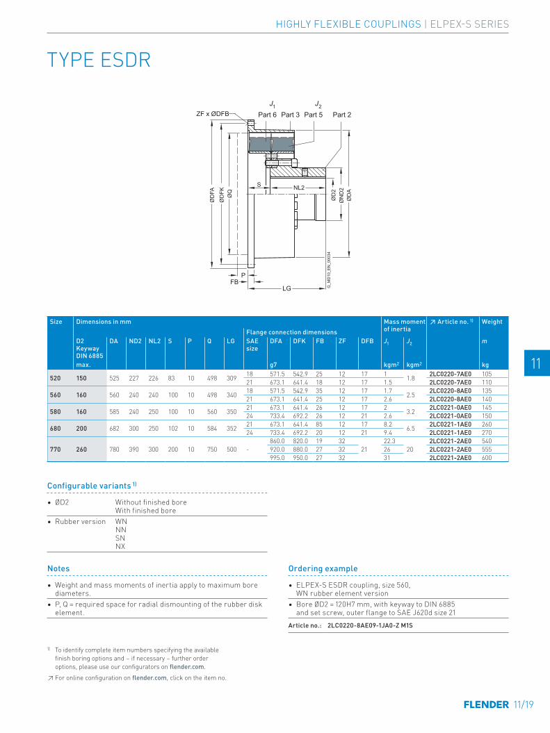
TYPE ESDR
ZF x ØDFB
ØD
2
ØD
A
ØQ
ØD
FK
ØD
FA
ØN
D2
S NL2
P
LGFB
1J 2JPart 6 Part 3 Part 5 Part 2
G_M
D10
_EN
_000
34Size Dimensions in mm Mass moment
of inertia↗ Article no. 1) Weight
Flange connection dimensionsD2 Keyway DIN 6885
DA ND2 NL2 S P Q LG SAE size
DFA DFK FB ZF DFB J1 J2 m
max. g7 kgm2 kgm2 kg
520 150 525 227 226 83 10 498 309 18 571.5 542.9 25 12 17 1 1.8 2LC0220-7AE0 105 .-.HA021 673.1 641.4 18 12 17 1.5 2LC0220-7AE0 110 .-.JA0
560 160 560 240 240 100 10 498 340 18 571.5 542.9 35 12 17 1.7 2.5 2LC0220-8AE0 135 .-.HA021 673.1 641.4 25 12 17 2.6 2LC0220-8AE0 140 .-.JA0
580 160 585 240 250 100 10 560 350 21 673.1 641.4 26 12 17 2 3.2 2LC0221-0AE0 145 .-.JA024 733.4 692.2 26 12 21 2.6 2LC0221-0AE0 150 .-.KA0
680 200 682 300 250 102 10 584 352 21 673.1 641.4 85 12 17 8.2 6.5 2LC0221-1AE0 260 .-.JA024 733.4 692.2 20 12 21 9.4 2LC0221-1AE0 270 .-.KA0
770 260 780 390 300 200 10 750 500 -860.0 820.0 19 32
2122.3
202LC0221-2AE0 540 .-.LA0
920.0 880.0 27 32 26 2LC0221-2AE0 555 .-.MA0995.0 950.0 27 32 31 2LC0221-2AE0 600 .-.NA0
Ordering example
• ELPEX-S ESDR coupling, size 560, WN rubber element version
• Bore ØD2 = 120H7 mm, with keyway to DIN 6885 and set screw, outer flange to SAE J620d size 21
Article no.: 2LC0220-8AE09-1JA0-Z M1S
Notes
• Weight and mass moments of inertia apply to maximum bore diameters.
• P, Q = required space for radial dismounting of the rubber disk element.
1) To identify complete item numbers specifying the available finish boring options and – if necessary – further order options, please use our configurators on flender.com.↗ For online configuration on flender.com, click on the item no.
Configurable variants 1)
• ØD2 Without finished bore With finished bore
• Rubber version WN NN SN NX
11/19
E E
4 4
5 5
6 6
7 7
8 8
9 9
10 10
11 11
12 12
13 13
A A
HIGHLY FLEXIBLE COUPLINGS | ELPEX-S SERIES

TYPE ESNW
1J 2J
ØD
2
ØD
AØ
ND
2
ØD
1Ø
ND
1
L3 L4
SNL1 NL2
LG
Part 3Part 1 Part 6 Part 2
G_M
D10
_EN
_000
36
Notes
• Weight and mass moments of inertia apply to maximum bore diameters.
Ordering example
• ELPEX-S ESNW coupling, size 520, WN rubber element version
• Bore ØD1 140H7 mm, keyway to DIN 6885 and set screw• Bore ØD2 120H7 mm, keyway to DIN 6885 and set screwArticle no.: 2LC0220-7AG99-1AA0-Z L1V+M1S
Size Dimensions in mm Mass moment of inertia ↗ Article no. 1) WeightD1/D2 Keyway DIN 6885
DA ND1/ND2 NL1/NL2 L3 L4 S LG J1 J2 m
max. kgm2 kgm2 kg265 50 275 78 65 62 66 68 198 0.11 0.017 2LC0220-1AG 15 -.AA0290 50 325 78 65 62 68 89 219 0.21 0.028 2LC0220-2AG 22 -.AA0320 65 365 98 87 84 92 105 279 0.37 0.042 2LC0220-3AG 32 -.AA0360 85 365 123 88 85 96 123 299 0.45 0.11 2LC0220-4AG 43 -.AA0420 100 480 155 85 82 94 134 304 1.5 0.3 2LC0220-5AG 75 -.AA0465 130 480 190 119 116 119 125 363 1.6 0.54 2LC0220-6AG 89 -.AA0520 150 585 227 162 159 161 123 447 4 0.94 2LC0220-7AG 155 -.AA0560 150 585 240 180 174 174 132 492 4.1 1.2 2LC0220-8AG 160 -.AA0580 160 685 240 200 195 198 145 545 5.5 1.6 2LC0221-0AG 185 -.AA0680 200 685 300 210 205 201 150 570 12 3.6 2LC0221-1AG 315 -.AA0770 260 870 390 255 250 253 180 690 27.2 12 2LC0221-2AG 500 -.AA0
1) To identify complete item numbers specifying the available finish boring options and – if necessary – further order options, please use our configurators on flender.com.↗ For online configuration on flender.com, click on the item no.
Configurable variants 1)
• ØD1 Without finished bore With finished bore
• ØD2 Without finished bore With finished bore
• Rubber version WN NN SN NX
11/20
E E
4 4
5 5
6 6
7 7
8 8
9 9
10 10
11 11
12 12
13 13
A A
HIGHLY FLEXIBLE COUPLINGS | ELPEX-S SERIES

TYPE ESDW
Notes
• Weight and mass moments of inertia apply to maximum bore diameters.
Ordering example
• ELPEX-S ESDW coupling, size 520, WN rubber element version
• Bore ØD1 140H7 mm, keyway to DIN 6885 and set screw• Bore ØD2 120H7 mm, keyway to DIN 6885 and set screwArticle no.: 2LC0220-7AH99-1AA0-Z L1V+M1S
ØD
1
ØD
2
ØD
A
ØN
D1
ØN
D2S NL2NL1
L3 L4
LG
1J 2JPart 6 Part 3 Part 5 Part 2Part 1
G_M
D10
_EN
_000
37
Size Dimensions in mm Mass moment of inertia ↗ Article no. 1) WeightD1/D2 Keyway DIN 6885
DA ND1/ND2 NL1/NL2 L3 L4 S LG J1 J2 m
max. kgm2 kgm2 kg520 150 585 227 226 201 135 100 552 4.7 1.8 2LC0220-7AH 215 -.AA0560 160 585 240 240 215 133 114 594 5.4 2.5 2LC0220-8AH 250 -.AA0580 160 685 240 250 220 140 120 620 10.1 3.2 2LC0221-0AH 300 -.AA0680 200 685 300 250 218 134 125 625 14.5 6.5 2LC0221-1AH 440 -.AA0770 260 870 390 300 265 238 220 820 40 20 2LC0221-2AH 720 -.AA0
1) To identify complete item numbers specifying the available finish boring options and – if necessary – further order options, please use our configurators on flender.com.↗ For online configuration on flender.com, click on the item no.
Configurable variants 1)
• ØD1 Without finished bore With finished bore
• ØD2 Without finished bore With finished bore
• Rubber version WN NN SN NX
11/21
E E
4 4
5 5
6 6
7 7
8 8
9 9
10 10
11 11
12 12
13 13
A A
HIGHLY FLEXIBLE COUPLINGS | ELPEX-S SERIES

TYPE EST
1J 2J
ZF x ØDFB
ØD
1
ØD
A
NL2
FBA LG
ØD
FAØ
DFK
Part 3 Part 5
G_M
D10
_EN
_000
35Size Taper
Clamping Bush
Dimensions in mm Mass moment of inertia
↗ Article no. 1) Weight
Flange connection dimensionsSize D1
Keyway DIN 6885DA NL2 A LG SAE
sizeDFA DFK FB ZF DFB J1 J2 m
min. max. kgm2 kgm2 kg
220 2012 14 50 222 32 0
52 6.5 215.9 200.0 6 6 8.5 0.008
0.008
2LC0220-0AF0 3.6 -.AA0
437.5 241.3 222.3 33 8 8.5 0.008 2LC0220-0AF0 3.5 -.BA08 263.5 244.5 8 6 10.5 0.011 2LC0220-0AF0 3.7 -.CA010 314.3 295.3 8 8 10.5 0.020 2LC0220-0AF0 4.2 -.DA0
265 2517 16 60 263 45 3 428 263.5 244.5 33 6
10.50.011
0.0192LC0220-1AF0 5.9 -.CA0
10 314.3 295.3 10 8 0.017 2LC0220-1AF0 6.2 -.DA011.5 352.4 333.4 10 8 0.024 2LC0220-1AF0 6.5 -.EA0
290 2517 16 60 290 64 6 58 10 314.3 295.3 16 8 10.5 0.026 0.026 2LC0220-2AF0 8.5 -.DA011.5 352.4 333.4 16 8 0.036 2LC0220-2AF0 8.8 -.EA0
320 3030 35 75 318 76 2 73 11.5 352.4 333.4 16 8 10.5 0.062 0.06 2LC0220-3AF0 14 -.EA014 466.7 438.2 16 8 13 0.18 2LC0220-3AF0 17 -.FA0
360 3535 35 90 353.5 89 13 76 11.5 352.4 333.4 54 8 10.5 0.065 0.13 2LC0220-4AF0 21 -.EA014 466.7 438.2 15 8 13 0.18 2LC0220-4AF0 24 -.FA0
420 4040 40 100 420 102 10 9214 466.7 438.2 18 8 13 0.22
0.332LC0220-5AF0 37 -.FA0
16 517.5 489.0 18 8 13 0.32 2LC0220-5AF0 38 -.GA018 571.5 542.9 18 6 17 0.47 2LC0220-5AF0 41 -.HA0
465 4545 55 110 465 115 28 8714 466.7 438.2 85 8 13 0.31
0.762LC0220-6AF0 63 -.FA0
16 517.5 489.0 27 8 13 0.41 2LC0220-6AF0 64 -.GA018 571.5 542.9 18 6 17 0.52 2LC0220-6AF0 68 -.HA0
Ordering example
• ELPEX-S EST coupling, size 265,WN rubber element version,with Taper clamping bush size 2517
• Bore ØD2 = 30 mm, outer flange to SAE J620d size 10Article no.: 2LC0220-1AF99-1DA0-Z M0S
Notes
• The rubber disk element cannot be dismounted until the machines have been moved.
• Weight and mass moments of inertia apply to maximum bore diameters.
1) To identify complete item numbers specifying the available finish boring options and – if necessary – further order options, please use our configurators on flender.com.
↗ For online configuration on flender.com, click on the item no.
Configurable variants 1)
• ØD1 Without finished bore With finished bore
• Rubber version WNNN SN NX
11/22
E E
4 4
5 5
6 6
7 7
8 8
9 9
10 10
11 11
12 12
13 13
A A
HIGHLY FLEXIBLE COUPLINGS | ELPEX-S SERIES

Size Taper Clamping Bush
Dimensions in mm Mass moment of inertia
↗ Article no. 1) Weight
Flange connection dimensionsSize D1
Keyway DIN 6885DA NL2 A LG SAE
sizeDFA DFK FB ZF DFB J1 J2 m
min. max. kgm2 kgm2 kg
220 2012 14 50 222 32 0
52 6.5 215.9 200.0 6 6 8.5 0.008
0.008
2LC0220-0AF0 3.6 -.AA0
437.5 241.3 222.3 33 8 8.5 0.008 2LC0220-0AF0 3.5 -.BA08 263.5 244.5 8 6 10.5 0.011 2LC0220-0AF0 3.7 -.CA010 314.3 295.3 8 8 10.5 0.020 2LC0220-0AF0 4.2 -.DA0
265 2517 16 60 263 45 3 428 263.5 244.5 33 6
10.50.011
0.0192LC0220-1AF0 5.9 -.CA0
10 314.3 295.3 10 8 0.017 2LC0220-1AF0 6.2 -.DA011.5 352.4 333.4 10 8 0.024 2LC0220-1AF0 6.5 -.EA0
290 2517 16 60 290 64 6 58 10 314.3 295.3 16 8 10.5 0.026 0.026 2LC0220-2AF0 8.5 -.DA011.5 352.4 333.4 16 8 0.036 2LC0220-2AF0 8.8 -.EA0
320 3030 35 75 318 76 2 73 11.5 352.4 333.4 16 8 10.5 0.062 0.06 2LC0220-3AF0 14 -.EA014 466.7 438.2 16 8 13 0.18 2LC0220-3AF0 17 -.FA0
360 3535 35 90 353.5 89 13 76 11.5 352.4 333.4 54 8 10.5 0.065 0.13 2LC0220-4AF0 21 -.EA014 466.7 438.2 15 8 13 0.18 2LC0220-4AF0 24 -.FA0
420 4040 40 100 420 102 10 9214 466.7 438.2 18 8 13 0.22
0.332LC0220-5AF0 37 -.FA0
16 517.5 489.0 18 8 13 0.32 2LC0220-5AF0 38 -.GA018 571.5 542.9 18 6 17 0.47 2LC0220-5AF0 41 -.HA0
465 4545 55 110 465 115 28 8714 466.7 438.2 85 8 13 0.31
0.762LC0220-6AF0 63 -.FA0
16 517.5 489.0 27 8 13 0.41 2LC0220-6AF0 64 -.GA018 571.5 542.9 18 6 17 0.52 2LC0220-6AF0 68 -.HA0
SPARE AND WEAR PARTS
Size ↗ Article No. set of rubber disk elements for a couplingCoupling typeEST ESN ESNR, ESNW ESD ESDR, ESDWwithout Taper clamping bush
with Taper clamping bush
WN rubber version220 2LC0220-0XL10-1AA0 2LC0220-0XL90-1AA0 2LC0220-0XJ00-1AA0265 2LC0220-1XL10-1AA0 2LC0220-1XL90-1AA0 2LC0220-1XJ00-1AA0 2LC0220-1XM00-1AA0290 2LC0220-2XL10-1AA0 2LC0220-2XL90-1AA0 2LC0220-2XJ00-1AA0 2LC0220-2XM00-1AA0320 2LC0220-3XL10-1AA0 2LC0220-3XL90-1AA0 2LC0220-3XJ00-1AA0 2LC0220-3XM00-1AA0360 2LC0220-4XL10-1AA0 2LC0220-4XL90-1AA0 2LC0220-4XJ00-1AA0 2LC0220-4XM00-1AA0420 2LC0220-5XL10-1AA0 2LC0220-5XL90-1AA0 2LC0220-5XJ00-1AA0 2LC0220-5XM00-1AA0465 2LC0220-6XL10-1AA0 2LC0220-6XL90-1AA0 2LC0220-6XJ00-1AA0 2LC0220-6XM00-1AA0520 2LC0220-7XJ00-1AA0 2LC0220-7XM00-1AA0 2LC0220-7XK00-1AA0 2LC0220-7XN00-1AA0560 2LC0220-8XJ00-1AA0 2LC0220-8XM00-1AA0 2LC0220-8XK00-1AA0 2LC0220-8XN00-1AA0580 2LC0221-0XJ00-1AA0 2LC0221-0XM00-1AA0 2LC0221-0XK00-1AA0 2LC0221-0XN00-1AA0680 2LC0221-1XJ00-1AA0 2LC0221-1XM00-1AA0 2LC0221-1XK00-1AA0 2LC0221-1XN00-1AA0770 2LC0221-2XM00-1AA0 2LC0221-2XN00-1AA0NN rubber version220 2LC0220-0XL10-2AA0 2LC0220-0XL90-2AA0 2LC0220-0XJ00-2AA0265 2LC0220-1XL10-2AA0 2LC0220-1XL90-2AA0 2LC0220-1XJ00-2AA0 2LC0220-1XM00-2AA0290 2LC0220-2XL10-2AA0 2LC0220-2XL90-2AA0 2LC0220-2XJ00-2AA0 2LC0220-2XM00-2AA0320 2LC0220-3XL10-2AA0 2LC0220-3XL90-2AA0 2LC0220-3XJ00-2AA0 2LC0220-3XM00-2AA0360 2LC0220-4XL10-2AA0 2LC0220-4XL90-2AA0 2LC0220-4XJ00-2AA0 2LC0220-4XM00-2AA0420 2LC0220-5XL10-2AA0 2LC0220-5XL90-2AA0 2LC0220-5XJ00-2AA0 2LC0220-5XM00-2AA0465 2LC0220-6XL10-2AA0 2LC0220-6XL90-2AA0 2LC0220-6XJ00-2AA0 2LC0220-6XM00-2AA0520 2LC0220-7XJ00-2AA0 2LC0220-7XM00-2AA0 2LC0220-7XK00-2AA0 2LC0220-7XN00-2AA0560 2LC0220-8XJ00-2AA0 2LC0220-8XM00-2AA0 2LC0220-8XK00-2AA0 2LC0220-8XN00-2AA0580 2LC0221-0XJ00-2AA0 2LC0221-0XM00-2AA0 2LC0221-0XK00-2AA0 2LC0221-0XN00-2AA0680 2LC0221-1XJ00-2AA0 2LC0221-1XM00-2AA0 2LC0221-1XK00-2AA0 2LC0221-1XN00-2AA0770 2LC0221-2XM00-2AA0 2LC0221-2XN00-2AA0SN rubber version220 2LC0220-0XL10-3AA0 2LC0220-0XL90-3AA0 2LC0220-0XJ00-3AA0265 2LC0220-1XL10-3AA0 2LC0220-1XL90-3AA0 2LC0220-1XJ00-3AA0 2LC0220-1XM00-3AA0290 2LC0220-2XL10-3AA0 2LC0220-2XL90-3AA0 2LC0220-2XJ00-3AA0 2LC0220-2XM00-3AA0320 2LC0220-3XL10-3AA0 2LC0220-3XL90-3AA0 2LC0220-3XJ00-3AA0 2LC0220-3XM00-3AA0360 2LC0220-4XL10-3AA0 2LC0220-4XL90-3AA0 2LC0220-4XJ00-3AA0 2LC0220-4XM00-3AA0420 2LC0220-5XL10-3AA0 2LC0220-5XL90-3AA0 2LC0220-5XJ00-3AA0 2LC0220-5XM00-3AA0465 2LC0220-6XL10-3AA0 2LC0220-6XL90-3AA0 2LC0220-6XJ00-3AA0 2LC0220-6XM00-3AA0520 2LC0220-7XJ00-3AA0 2LC0220-7XM00-3AA0 2LC0220-7XK00-3AA0 2LC0220-7XN00-3AA0560 2LC0220-8XJ00-3AA0 2LC0220-8XM00-3AA0 2LC0220-8XK00-3AA0 2LC0220-8XN00-3AA0580 2LC0221-0XJ00-3AA0 2LC0221-0XM00-3AA0 2LC0221-0XK00-3AA0 2LC0221-0XN00-3AA0680 2LC0221-1XJ00-3AA0 2LC0221-1XM00-3AA0 2LC0221-1XK00-3AA0 2LC0221-1XN00-3AA0770 2LC0221-2XM00-3AA0 2LC0221-2XN00-3AA0NX rubber version220 2LC0220-0XL10-4AA0 2LC0220-0XL90-4AA0 2LC0220-0XJ00-4AA0265 2LC0220-1XL10-4AA0 2LC0220-1XL90-4AA0 2LC0220-1XJ00-4AA0 2LC0220-1XM00-4AA0290 2LC0220-2XL10-4AA0 2LC0220-2XL90-4AA0 2LC0220-2XJ00-4AA0 2LC0220-2XM00-4AA0320 2LC0220-3XL10-4AA0 2LC0220-3XL90-4AA0 2LC0220-3XJ00-4AA0 2LC0220-3XM00-4AA0360 2LC0220-4XL10-4AA0 2LC0220-4XL90-4AA0 2LC0220-4XJ00-4AA0 2LC0220-4XM00-4AA0420 2LC0220-5XL10-4AA0 2LC0220-5XL90-4AA0 2LC0220-5XJ00-4AA0 2LC0220-5XM00-4AA0465 2LC0220-6XL10-4AA0 2LC0220-6XL90-4AA0 2LC0220-6XJ00-4AA0 2LC0220-6XM00-4AA0520 2LC0220-7XJ00-4AA0 2LC0220-7XM00-4AA0 2LC0220-7XK00-4AA0 2LC0220-7XN00-4AA0560 2LC0220-8XJ00-4AA0 2LC0220-8XM00-4AA0 2LC0220-8XK00-4AA0 2LC0220-8XN00-4AA0580 2LC0221-0XJ00-4AA0 2LC0221-0XM00-4AA0 2LC0221-0XK00-4AA0 2LC0221-0XN00-4AA0680 2LC0221-1XJ00-4AA0 2LC0221-1XM00-4AA0 2LC0221-1XK00-4AA0 2LC0221-1XN00-4AA0770 2LC0221-2XM00-4AA0 2LC0221-2XN00-4AA0
Notes
• The ELPEX-S coupling rubber disk elements are wear parts. The service life depends on the operating conditions.
Rubber disk elements
11/23
E E
4 4
5 5
6 6
7 7
8 8
9 9
10 10
11 11
12 12
13 13
A A
HIGHLY FLEXIBLE COUPLINGS | ELPEX-S SERIES

11/24

HIGHLY FLEXIBLE COUPLINGS – ELPEX SERIES
ELPEX
01-Einzelschilder-03-2020.indd 7 09.03.20 14:00
General 12/3Benefits 12/3Application 12/3Design and configurations 12/4Configuration 12/5Technical specifications 12/7
Type ENG 12/8
Type ENGS – with fail-safe device 12/10
Types EFG 12/12
Types EFGS – with fail-safe device 12/14
Spare and wear parts 12/16
12/1
E E
4 4
5 5
6 6
7 7
8 8
9 9
10 10
11 11
12 12
13 13
A A
HIGHLY FLEXIBLE COUPLINGS | ELPEX SERIES

12/2
E E
4 4
5 5
6 6
7 7
8 8
9 9
10 10
11 11
12 12
13 13
A A
HIGHLY FLEXIBLE COUPLINGS | ELPEX SERIES

GENERAL
Benefits
The ELPEX coupling is suitable for horizontal and vertical mounting positions or mounting at any required angle. The coupling parts can be arranged as required on the shafts to be connected.
The split flexible rings can be changed without having to move the coupled machines.
The flexible rings are mounted without backlash and give the coupling progressive torsional stiffness, i.e. torsional stiffness increases in proportion to coupling load.
The ELPEX coupling is especially suitable for reversing operation or operation with changing directions of load.
The coupling is delivered preassembled. The flexible rings are completely assembled. On the type ENG, the coup-ling halves have to be bolted together after the hub has been mounted. On the type EFG, after mounting the coup-ling hub, only the outer flange has to be connected to the machine.
Outer flanges with different connection dimensions are available for the type EFG.
If the flexible rings are irreparably damaged or worn, the metal parts can rotate freely against one another, they are not in contact with one another.
Application
The ELPEX coupling is available in 9 sizes with a nominal torque of between 1600 Nm and 90000 Nm. The coupling is suitable for ambient temperatures of between -40 °C and +80 °C.
The ELPEX coupling is frequently used for high-quality drives which have to guarantee very long service life in harsh operating conditions.
Examples of applications are mill drives in the cement industry, marine main and secondary drives or drives on large excavators powered by an electric motor or diesel engine.
ELPEX couplings are highly torsionally flexible and free of torsional backlash. Because of their low torsional stiffness and damping capacity, ELPEX couplings are especially suitable for coupling machines with a very non uniform torque pattern. ELPEX couplings are also suitable for connecting machines with high shaft misalignment. Standard ELPEX coupling types are designed as shaft-shaft connections or flange-shaft connections. Application-related types can be implemented on request.
12/3
E E
4 4
5 5
6 6
7 7
8 8
9 9
10 10
11 11
12 12
13 13
A A
HIGHLY FLEXIBLE COUPLINGS | ELPEX SERIES

GENERAL
Materials
TypeCast iron Steel
Hub part 1 Grey cast iron EN-GJL-250 SteelHub part 2 Steel SteelRetaining ring, outer ENG, ENGS Grey cast iron EN-GJL-250 SteelOuter flange EFG, EFGS Grey cast iron EN-GJL-250 Steel
Flexible ring materials
Material/Description
Hardness Marking Ambient temperature
Natural rubber 70 ShoreA Size - 2 -40 ... +80 °C
G_M
D10
_XX
_000
38
ENG
ENGS
G_M
D10
_XX
_000
39
EFG
EFGS
Types EFG/EFGSTypes ENG/ENGS
ELPEX coupling types
Type DescriptionENG Coupling as shaft-shaft connection EFG Coupling as flange-shaft connectionENGS as ENG with fail-safe deviceEFGS as EFG with fail-safe device
The following versions have already been implemented a number of times:
• ELPEX coupling with brake drum, brake disk or flywheel mass
• ELPEX coupling with axial backlash limiter• ELPEX coupling with adapter• ELPEX coupling in combination with a safety slip
clutch• ELPEX coupling for engaging/disengaging during stand-
still ELPEX coupling as part of a coupling combination
Further application-specific coupling types are available. Dimension sheets for and information on these are available on request.
Design and configurations
The ELPEX coupling's transmission characteristic is determined essentially by the flexible rings. The flexible rings are manufactured from a natural rubber mixture with a multiply fabric lining. The flexible rings are split so that they can be changed without having to move the coupled machines.
The flexible rings are fastened to the hub with a clamping ring and to the outer flange with a clamping ring, using pins and bolts.
On the EFG type, the outer flange is designed with connection dimensions for connection to e.g. a diesel engine flywheel. On ENG types, the outer flange is fitted to a second hub part, which then enables the shaft-shaft connection.
12/4
E E
4 4
5 5
6 6
7 7
8 8
9 9
10 10
11 11
12 12
13 13
A A
HIGHLY FLEXIBLE COUPLINGS | ELPEX SERIES

Fail-safe device of ELPEX coupling
Types ENGS and EFGS are provided with a fail-safe device. In normal operation the torsion angle of the flexible rings is smaller than the gap between the cams. In normal operation there is no metal-metal contact.If the flexible rings fail, cams transmit the torque from the inner part and outer part. These enable the coupling to be used in emergency mode for a short time. This option is frequently required e.g. in the case of marine drives.
G_MD10_XX_00040
A
A
A - A
Fail-safe device
Configuration
Coupling selection
The ELPEX-S coupling is especially suitable for rough operating environments. An application factor lower than that in Chapter E is therefore sufficient for all applications.
In the case of machines which excite torsional vibration, Flender urgently recommends carrying out a torsional vibration calculation or measuring the coupling load occurring in the drive.
Coupling load in continuous operation
The operating principles of the driving and driven machines are divided into categories and the applica-tion factor FB derived from these in accordance with DIN 3990-1.
Application factor FBTorque characteristic of the driven machineuniform with moderate shock loads
non uniform very rough
Electric motors, hydraulic motors, gas and water turbines
1.0 1.3 1.4
Internal-combustion engines 1.3 1.4 1.6
Temperature factor FTTemperature Ta on the coupling
Coupling Elastomer material
-40 up to -30 °C
-30 up to +50 °C
up to 60 °C
up to 70 °C
up to 80 °C
ELPEX NR 1.1 1.0 1.25 1.40 1.60
NR = Natural rubber mixture
Coupling size TKN ≥ TN ⋅ FB ⋅ FT
Examples of torque characteristic in driven machines:• uniform with moderate shock loads:
Generators, fans, blowers • non uniform: Reciprocating compressors, mixers,
conveyor systems• very rough: crushers, excavators, presses, mills
12/5
E E
4 4
5 5
6 6
7 7
8 8
9 9
10 10
11 11
12 12
13 13
A A
HIGHLY FLEXIBLE COUPLINGS | ELPEX SERIES
GENERAL
Coupling load under maximum and overload conditions
The maximum torque is the highest load acting on the coupling in normal operation. Maximum torques at a frequency of up to 25 times an hour are permitted and must be lower than the maximum coup-ling torque. Examples of maximum torque conditions are: Starting operations, stopping operations or usual opera-ting conditions with maximum load.
TKmax ≥ TMax ⋅ FT
Overload torques are maximum loads which occur only in combination with special, infrequent operating conditions. Examples of overload torque conditions are: Motor short circuit, emergency stop or blocking because of component breakage. Overload torques at a frequency of once a month are permitted and must be lower than the maximum over-load torque of the coupling. The overload condition may last only a short while, i.e. fractions of a second.
TKOL ≥ TOL ⋅ FT
Coupling load due to dynamic torque load
Applying the frequency factor FF, the dynamic torque load must be lower than the coupling fatigue torque.
Dynamic torque load
TKW ≥ TW ⋅ FT ⋅ FF
Frequency of the dynamic torque load ferr ≤ 10 Hz frequency factor FF = 1.0
Frequency of the dynamic torque load ferr > 10 Hz frequency factor FF = √(ferr/10 Hz)
Checking the maximum speed
For all load situations nKmax ≥ nmax
Checking permitted shaft misalignment and restorative forces
For all load situations, the actual shaft misalignment must be less than the permitted shaft misalignment.
Checking bore diameter, mounting geometry and coupling design
The check must be made on the basis of the dimension tables. On request, couplings with adapted geometry can be provided.
Checking shaft-hub connection
For any information on this, please refer to Page E/18.
Checking low temperature and chemically aggressive environment
The permitted coupling temperature is specified in the Temperature Factor FT table. In the case of chemically aggressive environments, please consult the manufac-turer.
12/6
E E
4 4
5 5
6 6
7 7
8 8
9 9
10 10
11 11
12 12
13 13
A A
HIGHLY FLEXIBLE COUPLINGS | ELPEX SERIES

Torsional stiffness and damping
The dynamic torsional stiffness is load-dependent and increases in proportion to capacity utilization. The values specified in the selection table apply to a capacity utili-zation of 100 %. The following table shows the correction factors for different rated loads.
CTdyn = CTdyn 1000 % ⋅ FKC
Load TN / TKN
20% 50% 60% 70% 80% 100% 200%Correction factor FKC 0.3 0.56 0.65 0.74 0.82 1 1.9
The damping coefficient is Ψ = 1.1
Torsional stiffness also depends on the ambient tempe-rature and the frequency and amplitude of the torsional vibration excitation. More precise torsional stiffness and damping parameters on request.
With flexible couplings the manufacturing process of the rubber elements and their aging primarily influence the stiffness value CTdyn. For this reason calculation must be made with a tolerance for the dynamic stiffness of ± 20 %. The specified damping coefficient Ψ is a minimum value with the result that the damping performance of the coupling corresponds at least to the specified value.
Permitted shaft misalignment
The permitted shaft misalignment depends on the operating speed. As the speed increases, lower shaft misalignment values are permitted. The correction factors for different speeds are specified in the following table. The maximum speed for the respective coupling size must be noted!
∆Kperm = ∆K1500 ⋅ FKV
Speed in rpm500 1000 1500 3000
Correction factor FKV 1.6 1.25 1.0 0.7
Power ratings of the ELPEX seriesSize Rated torque Maximum
torqueOverload torque
Fatigue torque Dynamic torsional stiffness for 100 % load
Stiffness Permitted shaft misalignment at speed n = 1500 rpm
Axial Radial Axial Radial AngleTKN TKmax TKOL TKW CTdyn Ca Cr ∆Ka ∆Kr ∆KwNm Nm Nm Nm kNm/rad N/mm mm mm mm ̊
270 1600 4800 6400 640 22 660 770 2.2 2.2 0.2320 2800 8400 11200 1120 38 780 910 2.6 2.6 0.2375 4500 13500 18000 1800 63 970 1130 3 3 0.2430 7100 21300 28400 2840 97 1160 1350 3.4 3.4 0.2500 11200 33600 44800 4480 155 1410 1630 3.8 3.8 0.2590 18000 54000 72000 7200 240 1710 1990 4.2 4.2 0.2690 28000 84000 112000 11200 365 2060 2390 4.6 4.6 0.2840 45000 135000 180000 18000 685 2570 2990 5 5 0.2970 90000 270000 360000 36000 1100 3020 3510 5.5 5.5 0.2
Technical specifications
12/7
E E
4 4
5 5
6 6
7 7
8 8
9 9
10 10
11 11
12 12
13 13
A A
HIGHLY FLEXIBLE COUPLINGS | ELPEX SERIES

TYPE ENG
ØN
D2
U2U1
ØD
2ØN
D1
ØD
A
ØD
1
LGNL1 NL2
S
W
LGNL1 NL2S
V V V V
J1 J2
G_M
D10
_EN
_000
41a
Part 1
Sizes 270 ... 430 Sizes 500 ... 970
Part 2
Size Rated torque
Maximum speed
Dimensions in mm Mass moment of inertia
Article no. 1) Weight
TypeCast iron
Steel Keyway DIN 6885 Type
TKN nKmax nKmax D1 D2 DA ND1 ND2 NL1 NL2 S U1 U2 W LG J1 J2 Cast iron Steel mNm rpm rpm min. max. min. max. kgm2 kgm2 kg
270 1600 3000 4250 45 80 45 70 270 128 94 80 155 10 14 86 42 245 0.21 0.037 2LC0200-3AF 2LC0200-3AL 29 -0AA0320 2800 2500 3600 55 100 55 85 320 160 115 100 180 6 16 97.5 48 286 0.49 0.082 2LC0200-4AF 2LC0200-4AL 50 -0AA0375 4500 2100 3100 65 115 65 105 375 184 143 120 205 10 18 111.8 62 335 1.0 0.21 2LC0200-5AF 2LC0200-5AL 80 -0AA0430 7100 1900 2650 75 130 75 120 430 208 165 140 235 8 22 126 68 383 2.0 0.37 2LC0200-6AF 2LC0200-6AL 113 -0AA0500 11200 1600 2300 90 150 90 150 500 240 202 160 160 112 25 139.7 80 432 3.9 0.85 2LC0200-7AF 2LC0200-7AL 174 -0AA0
590 18000 1360 2000 100 140 100 170 590 224 230 190 190 130 28 162.7 95 510 8.2 1.7 2LC0200-8AF 2LC0200-8AL 254 -0AA0140 180 288 8.4 284
690 28000 1200 1650110 140
110 200 690224
278 220 220 140 32 175.6 102 58016.3
3.7 2LC0201-0AF 2LC0201-0AL350
-0AA0140 180 288 16.8 370180 210 336 16.9 385
840 45000 1000 1350 140 180 140 240 840 288 340 280 280 125 42 231 105 685 49 11 2LC0201-1AF 2LC0201-1AL 700 -0AA0180 220 352 50 725
970 90000 850 1180
160 200
160 280 970
320
390 350 350 167 70 290 137 867
104
26 2LC0201-2AF 2LC0201-2AL
1265
-0AA0200 240 384 106 1310240 280 448 110 1350280 320 512 115 1410
Configurable variants 1)
• ØD1 Without finished bore With finished bore
• ØD2 Without finished bore With finished bore
1) To identify complete item numbers specifying the available finish boring options and – if necessary – further order options, please use our configurators on flender.com.↗ For online configuration on flender.com, click on the item no.
12/8
E E
4 4
5 5
6 6
7 7
8 8
9 9
10 10
11 11
12 12
13 13
A A
HIGHLY FLEXIBLE COUPLINGS | ELPEX SERIES
Notes
• The hub diameter of the component part is assigned according to the diameter of the finished bore. Where bore diameters overlap, the component with the smaller hub diameter is always selected.
• Weights and mass moments of inertia apply to cast iron version with maximum bore.
• From size 500, the bores D1 and D2 are each provided with a recess of D = +1 mm halfway along the hub. V ≈ 1/3 NL.
Ordering example
• ELPEX ENG coupling, size 690, cast iron version• Bore ØD1 = 180H7 mm with keyway to DIN 6885 and set screw,
the hub diameter ND1 = 288 mm is thus assigned• Bore ØD2 = 200H7 mm with keyway to DIN 6885 and set screw,
the hub diameter ND2 = 278 mm is thus assignedArticle no.: 2LC0201-0AF99-0AA0-Z L2B+M2D
1) To identify complete item numbers specifying the available finish boring options and – if necessary – further order options, please use our configurators on flender.com.↗ For online configuration on flender.com, click on the item no.
12/9
E E
4 4
5 5
6 6
7 7
8 8
9 9
10 10
11 11
12 12
13 13
A A
HIGHLY FLEXIBLE COUPLINGS | ELPEX SERIES

TYPE ENGS with fail-safe device
ØN
D2
U2U1
ØD
2ØN
D1
ØD
A
ØD
1
LGNL1 NL2
S
W
LGNL1 NL2S
V V V V
J1 J2
G_M
D10
_EN
_000
41a
Part 1
Sizes 270 ... 430 Sizes 500 ... 970
Part 2
Size Rated torque
Maximum speed
Dimensions in mm Mass moment of inertia
Article no. 1) Weight
TypeCast iron
Steel Keyway DIN 6885 Type
TKN nKmax nKmax D1 D2 DA ND1 ND2 NL1 NL2 S U1 U2 W LG J1 J2 Cast iron Steel mNm rpm rpm min. max. min. max. kgm2 kgm2 kg
270 1600 3000 4250 45 80 45 70 270 128 94 80 155 10 14 86 42 245 0.21 0.037 2LC0200-3AG 2LC0200-3AM 29 -0AA0320 2800 2500 3600 55 100 55 85 320 160 115 100 180 6 16 97.5 48 286 0.49 0.082 2LC0200-4AG 2LC0200-4AM 50 -0AA0375 4500 2100 3100 65 115 65 105 375 184 143 120 205 10 18 111.8 62 335 1.0 0.21 2LC0200-5AG 2LC0200-5AM 80 -0AA0430 7100 1900 2650 75 130 75 120 430 208 165 140 235 8 22 126 68 383 2.0 0.37 2LC0200-6AG 2LC0200-6AM 113 -0AA0500 11200 1600 2300 90 150 90 150 500 240 202 160 160 112 25 139.7 80 432 3.9 0.85 2LC0200-7AG 2LC0200-7AM 174 -0AA0
590 18000 1360 2000 100 140 100 170 590 224 230 190 190 130 28 162.7 95 510 8.2 1.7 2LC0200-8AG 2LC0200-8AM 254 -0AA0140 180 288 8.4 284
690 28000 1200 1650110 140
110 200 690224
278 220 220 140 32 175.6 102 58016.3
3.7 2LC0201-0AG 2LC0201-0AM350
-0AA0140 180 288 16.8 370180 210 336 16.9 385
840 45000 1000 1350 140 180 140 240 840 288 340 280 280 125 42 231 105 685 49 11 2LC0201-1AG 2LC0201-1AM 700 -0AA0180 220 352 50 725
970 90000 850 1180
160 200
160 280 970
320
390 350 350 167 70 290 137 867
104
26 2LC0201-2AG 2LC0201-2AM
1265
-0AA0200 240 384 106 1310240 280 448 110 1350280 320 512 115 1410
Configurable variants 1)
• ØD1 Without finished bore With finished bore
• ØD2 Without finished bore With finished bore
1) To identify complete item numbers specifying the available finish boring options and – if necessary – further order options, please use our configurators on flender.com.↗ For online configuration on flender.com, click on the item no.
12/10
E E
4 4
5 5
6 6
7 7
8 8
9 9
10 10
11 11
12 12
13 13
A A
HIGHLY FLEXIBLE COUPLINGS | ELPEX SERIES

Notes
• The hub diameter of the component part is assigned according to the diameter of the finished bore. Where bore diameters overlap, the component with the smaller hub diameter is always selected.
• Weights and mass moments of inertia apply to cast iron version with maximum bore.
• From size 500, the bores D1 and D2 are each provided with a recess of D = +1 mm halfway along the hub. V ≈ 1/3 NL.
Ordering example
• ELPEX ENGS coupling, size 690, cast iron version• Bore ØD1 = 180H7 mm with keyway to DIN 6885 and set screw,
the hub diameter ND1 = 288 mm is thus assigned• Bore ØD2 = 200H7 mm with keyway to DIN 6885 and set screw,
the hub diameter ND2 = 278 mm is thus assignedArticle no.: 2LC0201-0AG99-0AA0-Z L2B+M2D
1) To identify complete item numbers specifying the available finish boring options and – if necessary – further order options, please use our configurators on flender.com.↗ For online configuration on flender.com, click on the item no.
12/11
E E
4 4
5 5
6 6
7 7
8 8
9 9
10 10
11 11
12 12
13 13
A A
HIGHLY FLEXIBLE COUPLINGS | ELPEX SERIES

TYPES EFG
ØD
2
W
LGNL2
ØD
FKØ
DFA
FB
ØN
D2
ØD
A
ZFxDFB
NL2SLG
V V
J1 J2
G_M
D10
_EN
_000
42a
Part 3
Sizes270 ... 430
Sizes500 ... 970
Part 2
Size Rated torque
Maximum speed
Dimensions in mm Mass moment of inertia
Article no. 1) Weight
TypeCast iron
Steel Flange connection dimensions 2)
Type
TKN nKmax nKmax D2 Keyway DIN 6885
DA ND2 NL2 S W LG DFA DFK FB ZF DFB J1 J2 Cast iron Steel m
Nm rpm rpm min. max. kgm2 kgm2 kg
270 1600 3000 4250 45 70 270 94 155 - 42 155466.7g7
2) 438.22)12
8 13 0.470.037
2LC0200-3AB2 2LC0200-3AJ2 27 -0AA0325j6 300 8 14 0.16 2LC0200-3AB1 2LC0200-3AJ1 19 -0AA0
320 2800 2500 3600 55 85 320 115 180 - 48 180517.5g7
2) 4892)14
8 13 0.870.082
2LC0200-4AB2 2LC0200-4AJ2 42 -0AA0392j6 360 8 18 0.39 2LC0200-4AB1 2LC0200-4AJ1 33.5 -0AA0
375 4500 2100 3100 65 105 375 143 205 - 62 205571.5g7
2) 542.92)16
6 17 1.50.21
2LC0200-5AB2 2LC0200-5AJ2 65 -0AA0448j6 415 8 18 0.78 2LC0200-5AB1 2LC0200-5AJ1 53 -0AA0
430 7100 1900 2650 75 120 430 165 235 - 68 235673.1g7
2) 641.42)20
12 17 3.40.37
2LC0200-6AB2 2LC0200-6AJ2 100 -0AA0515j6 475 8 22 1.5 2LC0200-6AB1 2LC0200-6AJ1 78 -0AA0
500 11200 1600 2300 90 150 500 202 160 100 80 260673.1g7
2) 641.42)20
12 17 4.00.85
2LC0200-7AB2 2LC0200-7AJ2 150 -0AA0585j6 545 10 22 2.7 2LC0200-7AB1 2LC0200-7AJ1 140 -0AA0
1) To identify complete item numbers specifying the available finish boring options and – if necessary – further order options, please use our configurators on flender.com.2) The upper line for the flange connection dimensions complies with standard SAE J620d or DIN 6288.↗ For online configuration on flender.com, click on the item no.
Configurable variants 1)
• ØD2 Without finished bore With finished bore
12/12
E E
4 4
5 5
6 6
7 7
8 8
9 9
10 10
11 11
12 12
13 13
A A
HIGHLY FLEXIBLE COUPLINGS | ELPEX SERIES

Size Rated torque
Maximum speed
Dimensions in mm Mass moment of inertia
Article no. 1) Weight
TypeCast iron
Steel Flange connection dimensions 2)
Type
TKN nKmax nKmax D2 Keyway DIN 6885
DA ND2 NL2 S W LG DFA DFK FB ZF DFB J1 J2 Cast iron Steel m
Nm rpm rpm min. max. kgm2 kgm2 kg
270 1600 3000 4250 45 70 270 94 155 - 42 155466.7g7
2) 438.22)12
8 13 0.470.037
2LC0200-3AB2 2LC0200-3AJ2 27 -0AA0325j6 300 8 14 0.16 2LC0200-3AB1 2LC0200-3AJ1 19 -0AA0
320 2800 2500 3600 55 85 320 115 180 - 48 180517.5g7
2) 4892)14
8 13 0.870.082
2LC0200-4AB2 2LC0200-4AJ2 42 -0AA0392j6 360 8 18 0.39 2LC0200-4AB1 2LC0200-4AJ1 33.5 -0AA0
375 4500 2100 3100 65 105 375 143 205 - 62 205571.5g7
2) 542.92)16
6 17 1.50.21
2LC0200-5AB2 2LC0200-5AJ2 65 -0AA0448j6 415 8 18 0.78 2LC0200-5AB1 2LC0200-5AJ1 53 -0AA0
430 7100 1900 2650 75 120 430 165 235 - 68 235673.1g7
2) 641.42)20
12 17 3.40.37
2LC0200-6AB2 2LC0200-6AJ2 100 -0AA0515j6 475 8 22 1.5 2LC0200-6AB1 2LC0200-6AJ1 78 -0AA0
500 11200 1600 2300 90 150 500 202 160 100 80 260673.1g7
2) 641.42)20
12 17 4.00.85
2LC0200-7AB2 2LC0200-7AJ2 150 -0AA0585j6 545 10 22 2.7 2LC0200-7AB1 2LC0200-7AJ1 140 -0AA0
Notes
• The hub diameter of the component part is assigned according to the diameter of the finished bore. Where bore diameters overlap, the component with the smaller hub diameter is always selected.
• Weights and mass moments of inertia apply to cast iron version with maximum bore.
• From size 500, the bores D1 and D2 are each provided with a recess of D = +1 mm halfway along the hub. V ≈ 1/3 NL.
• Notice: The application factor FB in the coupling selection Page 12/5 section must be noted.
Ordering example
• ELPEX EFG coupling, size 430, steel version• Bore ØD1 = 100H7 mm with keyway to DIN 6885 and set screw,
flange to SAE J620d size 21 with DFA = 673.5g7 mm• Coupling balanced G6.3 in accordance with the half parallel
key standard.Article no.: 2LC0200-6AJ29-0AA0-ZM1N+W02
1) To identify complete item numbers specifying the available finish boring options and – if necessary – further order options, please use our configurators on flender.com.2) The upper line for the flange connection dimensions complies with standard SAE J620d or DIN 6288.↗ For online configuration on flender.com, click on the item no.
Configurable variants 1)
• ØD2 Without finished bore With finished bore
Size Rated torque
Maximum speed
Dimensions in mm Mass moment of inertia
Article no. 1) Weight
TypeCast iron
Steel Flange connection dimensions 2)
Type
TKN nKmax nKmax D2 Keyway DIN 6885
DA ND2 NL2 S W LG DFA DFK FB ZF DFB J1 J2 Cast iron Steel m
Nm rpm rpm min. max. kgm2 kgm2 kg
590 18000 1350 2000 100 170 590 230 190 120 95 310733.4g7
2) 692.22)24
12 21 7.01.7
2LC0200-8AB2 2LC0200-8AJ2 200 -0AA0692j6 645 10 26 6.0 2LC0200-8AB1 2LC0200-8AJ1 190 -0AA0
690 28000 1200 1650 110 200 690 278 220 130 102 350890g7
2) 8502)24
32 17 153.7
2LC0201-0AB2 2LC0201-0AJ2 270 -0AA0800j6 750 12 26 11 2LC0201-0AB1 2LC0201-0AJ1 250 -0AA0
840 45000 1000 1350 140 240 840 340 280 115 105 3951105g7
2) 10602)30
32 21 4611
2LC0201-1AB2 2LC0201-1AJ2 530 -0AA0960j6 908 16 30 32 2LC0201-1AB1 2LC0201-1AJ1 470 -0AA0
970 90000 850 1180 160 280 970 390 350 155 137 5051385g7
2) 13202)35
24 31 13026
2LC0201-2AB2 2LC0201-2AJ2 1050 -0AA01112j6 1051 16 35 76 2LC0201-2AB1 2LC0201-2AJ1 920 -0AA0
12/13
E E
4 4
5 5
6 6
7 7
8 8
9 9
10 10
11 11
12 12
13 13
A A
HIGHLY FLEXIBLE COUPLINGS | ELPEX SERIES

TYPES EFGS with fail-safe device
ØD
2
W
LGNL2
ØD
FKØ
DFA
FB
ØN
D2
ØD
A
ZFxDFB
NL2SLG
V V
J1 J2
G_M
D10
_EN
_000
42a
Part 3
Sizes270 ... 430
Sizes500 ... 970
Part 2
Size Rated torque
Maximum speed
Dimensions in mm Mass moment of inertia
Article no. 1) Weight
TypeCast iron
Steel Flange connection dimensions 2)
Type
TKN nKmax nKmax D2 Keyway DIN 6885
DA ND2 NL2 S W LG DFA DFK FB ZF DFB J1 J2 Cast iron Steel m
Nm rpm rpm min. max. kgm2 kgm2 kg
270 1600 3000 4250 45 70 270 94 155 - 42 155466.7g7
2) 438.22)12
8 13 0.470.037
2LC0200-3AC2 2LC0200-3AK2 27 -0AA0325j6 300 8 14 0.16 2LC0200-3AC1 2LC0200-3AK1 19 -0AA0
320 2800 2500 3600 55 85 320 115 180 - 48 180517.5g7
2) 4892)14
8 13 0.870.082
2LC0200-4AC2 2LC0200-4AK2 42 -0AA0392j6 360 8 18 0.39 2LC0200-4AC1 2LC0200-4AK1 33.5 -0AA0
375 4500 2100 3100 65 105 375 143 205 - 62 205571.5g7
2) 542.92)16
6 17 1.50.21
2LC0200-5AC2 2LC0200-5AK2 65 -0AA0448j6 415 8 18 0.78 2LC0200-5AC1 2LC0200-5AK1 53 -0AA0
430 7100 1900 2650 75 120 430 165 235 - 68 235673.1g7
2) 641.42)20
12 17 3.40.37
2LC0200-6AC2 2LC0200-6AK2 100 -0AA0515j6 475 8 22 1.5 2LC0200-6AC1 2LC0200-6AK1 78 -0AA0
500 11200 1600 2300 90 150 500 202 160 100 80 260673.1g7
2) 641.42)20
12 17 4.00.85
2LC0200-7AC2 2LC0200-7AK2 150 -0AA0585j6 545 10 22 2.7 2LC0200-7AC1 2LC0200-7AK1 140 -0AA0
1) To identify complete item numbers specifying the available finish boring options and – if necessary – further order options, please use our configurators on flender.com.2) The upper line for the flange connection dimensions complies with standard SAE J620d or DIN 6288.↗ For online configuration on flender.com, click on the item no.
Configurable variants 1)
• ØD2 Without finished bore With finished bore
12/14
E E
4 4
5 5
6 6
7 7
8 8
9 9
10 10
11 11
12 12
13 13
A A
HIGHLY FLEXIBLE COUPLINGS | ELPEX SERIES

Size Rated torque
Maximum speed
Dimensions in mm Mass moment of inertia
Article no. 1) Weight
TypeCast iron
Steel Flange connection dimensions 2)
Type
TKN nKmax nKmax D2 Keyway DIN 6885
DA ND2 NL2 S W LG DFA DFK FB ZF DFB J1 J2 Cast iron Steel m
Nm rpm rpm min. max. kgm2 kgm2 kg
270 1600 3000 4250 45 70 270 94 155 - 42 155466.7g7
2) 438.22)12
8 13 0.470.037
2LC0200-3AC2 2LC0200-3AK2 27 -0AA0325j6 300 8 14 0.16 2LC0200-3AC1 2LC0200-3AK1 19 -0AA0
320 2800 2500 3600 55 85 320 115 180 - 48 180517.5g7
2) 4892)14
8 13 0.870.082
2LC0200-4AC2 2LC0200-4AK2 42 -0AA0392j6 360 8 18 0.39 2LC0200-4AC1 2LC0200-4AK1 33.5 -0AA0
375 4500 2100 3100 65 105 375 143 205 - 62 205571.5g7
2) 542.92)16
6 17 1.50.21
2LC0200-5AC2 2LC0200-5AK2 65 -0AA0448j6 415 8 18 0.78 2LC0200-5AC1 2LC0200-5AK1 53 -0AA0
430 7100 1900 2650 75 120 430 165 235 - 68 235673.1g7
2) 641.42)20
12 17 3.40.37
2LC0200-6AC2 2LC0200-6AK2 100 -0AA0515j6 475 8 22 1.5 2LC0200-6AC1 2LC0200-6AK1 78 -0AA0
500 11200 1600 2300 90 150 500 202 160 100 80 260673.1g7
2) 641.42)20
12 17 4.00.85
2LC0200-7AC2 2LC0200-7AK2 150 -0AA0585j6 545 10 22 2.7 2LC0200-7AC1 2LC0200-7AK1 140 -0AA0
Notes
• The hub diameter of the component part is assigned according to the diameter of the finished bore. Where bore diameters overlap, the component with the smaller hub diameter is always selected.
• Weights and mass moments of inertia apply to cast iron version with maximum bore.
• From size 500, the bores D1 and D2 are each provided with a recess of D = +1 mm halfway along the hub. V ≈ 1/3 NL.
• Notice: The application factor FB in the coupling selection Page 12/5 section must be noted.
Ordering example
• ELPEX EFGS coupling, size 430, steel version• Bore ØD1 = 100H7 mm with keyway to DIN 6885 and set screw,
flange to SAE J620d size 21 with DFA = 673.5g7 mm• Coupling balanced G6.3 in accordance with the half parallel
key standard.Article no.: 2LC0200-6AK29-0AA0-Z M1N+W02
1) To identify complete item numbers specifying the available finish boring options and – if necessary – further order options, please use our configurators on flender.com.2) The upper line for the flange connection dimensions complies with standard SAE J620d or DIN 6288.↗ For online configuration on flender.com, click on the item no.
Configurable variants 1)
• ØD2 Without finished bore With finished bore
Size Rated torque
Maximum speed
Dimensions in mm Mass moment of inertia
Article no. 1) Weight
TypeCast iron
Steel Flange connection dimensions 2)
Type
TKN nKmax nKmax D2 Keyway DIN 6885
DA ND2 NL2 S W LG DFA DFK FB ZF DFB J1 J2 Cast iron Steel m
Nm rpm rpm min. max. kgm2 kgm2 kg
590 18000 1350 2000 100 170 590 230 190 120 95 310733.4g7
2) 692.22)24
12 21 7.01.7
2LC0200-8AC2 2LC0200-8AK2 200 -0AA0692j6 645 10 26 6.0 2LC0200-8AC1 2LC0200-8AK1 190 -0AA0
690 28000 1200 1650 110 200 690 278 220 130 102 350890g7
2) 8502)24
32 17 153.7
2LC0201-0AC2 2LC0201-0AK2 270 -0AA0800j6 750 12 26 11 2LC0201-0AC1 2LC0201-0AK1 250 -0AA0
840 45000 1000 1350 140 240 840 340 280 115 105 3951105g7
2) 10602)30
32 21 4611
2LC0201-1AC2 2LC0201-1AK2 530 -0AA0960j6 908 16 30 32 2LC0201-1AC1 2LC0201-1AK1 470 -0AA0
970 90000 850 1180 160 280 970 390 350 155 137 5051385g7
2) 13202)35
24 31 13026
2LC0201-2AC2 2LC0201-2AK2 1050 -0AA01112j6 1051 16 35 76 2LC0201-2AC1 2LC0201-2AK1 920 -0AA0
12/15
E E
4 4
5 5
6 6
7 7
8 8
9 9
10 10
11 11
12 12
13 13
A A
HIGHLY FLEXIBLE COUPLINGS | ELPEX SERIES
Size ↗ Article no. set of flexible rings for a coupling
Weight
kg270 2LC0200-3XV00-0AA0 1.6320 2LC0200-4XV00-0AA0 2.6375 2LC0200-5XV00-0AA0 4.4430 2LC0200-6XV00-0AA0 6.8500 2LC0200-7XV00-0AA0 9.4590 2LC0200-8XV00-0AA0 18690 2LC0201-0XV00-0AA0 36840 2LC0201-1XV00-0AA0 68970 2LC0201-2XV00-0AA0 120
Size ↗ Article no. set of pins and boltsTypeEFG, ENG EFGS, ENGS
270 2LC0200-3XU00-0AA0 2LC0200-3XW00-0AA0320 2LC0200-4XU00-0AA0 2LC0200-4XW00-0AA0375 2LC0200-5XU00-0AA0 2LC0200-5XW00-0AA0430 2LC0200-6XU00-0AA0 2LC0200-6XW00-0AA0500 2LC0200-7XU00-0AA0 2LC0200-7XW00-0AA0590 2LC0200-8XU00-0AA0 2LC0200-8XW00-0AA0690 2LC0201-0XU00-0AA0 2LC0201-0XW00-0AA0840 2LC0201-1XU00-0AA0 2LC0201-1XW00-0AA0970 2LC0201-2XU00-0AA0 2LC0201-2XW00-0AA0
Flexible rings
Flexible ring screw connection
Note
• The flexible rings are wear parts. The service life depends on the operating conditions.
SPARE AND WEAR PARTS
12/16
E E
4 4
5 5
6 6
7 7
8 8
9 9
10 10
11 11
12 12
13 13
A A
HIGHLY FLEXIBLE COUPLINGS | ELPEX SERIES

12/17
E E
4 4
5 5
6 6
7 7
8 8
9 9
10 10
11 11
12 12
13 13
A A
HIGHLY FLEXIBLE COUPLINGS | ELPEX SERIES

12/18
APPENDIX
Fits A/2Fitting recommendations A/2Deviation table to DIN ISO 286 A/2Cylindrical shaft ends, extract from DIN 748 Part 1 (long) A/3Central holes according to DIN 332 Part 2 A/3
Parallel key connections to DIN 6885-1 A/4
Related catalogs A/6
Suitable gear solutions A/9
A/1
E E
4 4
5 5
6 6
7 7
8 8
9 9
10 10
11 11
12 12
13 13
A A
APPENDIX | FLENDER STANDARD COUPLINGS
FITS
Fitting recommendations
For many applications, the fit assignment m6/H7 is especially suitable.
Description Application Shaft tolerance Bore toleranceSliding fit with parallel key connection not suitable for reversing operation
For steel and cast hubs j6 H7h6 J7
Press fit with parallel key connection not suitable for reversing operation
For steel and cast hubs h6 K7k6 H7
Interference fit with parallel key connection suitable for reversing operation
For steel and cast hubs m6 H7n6 H7h6 M7
Only for steel hubsPreferred for ZAPEX and ARPEX coupling series.
h6 P7k6 M7m6 K7n6 J7p6 H7s6 F7
Shrink fit connection without parallel key Only for steel hubsThe permitted hub tension must be urgently checked.
u6 H6v6 H6x6 H6
Deviation table to DIN ISO 286 for above-mentioned fits for bore diameters from 10 mm to 250 mm
Bore diameter
Deviations in µmBore Shaft
above up to F7 H7 J7 K7 M7 P7 h6 j6 k6 m6 n6 p6
10 18+34 +18 +10 +6 0 -11 0 +8 +12 +18 +23 +29+16 0 -8 -12 -18 -29 -11 -3 +1 +7 +12 +18
18 30+41 +21 +12 +6 0 -14 0 +9 +15 +21 +28 +35+20 0 -9 -15 -21 -35 -13 -4 +2 +8 +15 +22
30 50+50 +25 +14 +7 0 -17 0 +11 +18 +25 +33 +42+25 0 -11 -18 -25 -42 -16 -5 +2 +9 +17 +26
50 80+60 +30 +18 +9 0 -21 0 +12 +21 +30 +39 +51+30 0 -12 -21 -30 -51 -19 -7 +2 +11 +20 +32
80 120+71 +35 +22 +10 0 -24 0 +13 +25 +35 +45 +59+36 0 -13 -25 -35 -59 -22 -9 +3 +13 +23 +37
120 180+83 +40 +26 +12 0 -28 0 +14 +28 +40 +52 +68+43 0 -14 -28 -40 -68 -25 -11 +3 +15 +27 +43
180 250+96 +46 +30 +13 0 -33 0 +16 +33 +46 +60 +79+50 0 -16 -33 -46 -79 -29 -13 +4 +17 +31 +50
A/2
E E
4 4
5 5
6 6
7 7
8 8
9 9
10 10
11 11
12 12
13 13
A A
FLENDER STANDARD COUPLINGS | APPENDIX

Cylindrical shaft ends, extract from DIN 748 Part 1 (long)
Diameter in mm24 25 28 30 32 35 38 40 42 45 48 50 55 60 65 70 75 80 85 90 95 100
ISO tolerance zone k6 m6End length in mm 50 60 80 110 140 170 210
Central holes according to DIN 332 Part 2
Parallel keyway
G_MD10_EN_00198
t2
d 6
d 2
d 3 d 4 d 5 60°
6,3
120°
d 1
t1t3t4t5
Form DS (with thread) DIN 332/2
Recommended diameter ranges d6 1)
DS form dimensionsd1 d2 2) d3 d4 d5 t1 t2 t3 t4 t5
above up to +2 min. +1 approx. approx. 7 10 M3 2.5 3.2 5.3 5.8 9 12 2.6 1.8 0.210 13 M4 3.3 4.3 6.7 7.4 10 14 3.2 2.1 0.313 16 M5 4.2 5.3 8.1 8.8 12.5 17 4 2.4 0.316 21 M6 5 6.4 9.6 10.5 16 21 5 2.8 0.421 24 M8 6.8 8.4 12.2 13.2 19 25 6 3.3 0.424 30 M10 8.5 10.5 14.9 16.3 22 30 7.5 3.8 0.630 38 M12 10.2 13 18.1 19.8 28 37 9.5 4.4 0.738 50 M16 14 17 23 25.3 36 45 12 5.2 1.050 85 M20 17.5 21 28.4 31.3 42 53 15 6.4 1.385 130 M24 21 25 34.2 38 50 63 18 8 1.6130 225 M30 3) 26.5 31 40.2 44.6 60 77 22 8 1.9225 320 M36 3) 32 37 49.7 55 74 93 22 11 2.3320 500 M42 3) 37.5 43 60.3 66.6 84 105 26 15 2.7
1) Diameter refers to the finished workpiece2) Tap hole drill diameter according to DIN 336 Part 13) Dimensions not acc. to DIN 332 Part 2
A/3
E E
4 4
5 5
6 6
7 7
8 8
9 9
10 10
11 11
12 12
13 13
A A
APPENDIX | FLENDER STANDARD COUPLINGS

PARALLEL KEY CONNECTIONS TO DIN 6885-1
ØD
+T2
T1
H
T2
ØD
B
G_M
D10
_XX
_001
72
For moderate operating conditions, the hub keyway tolerance JS9 is recommended.
In harsh operating conditions or during reversing opera-tion, the keyway width tolerance P9 must be preferred.
With two parallel keyways, the keyway width tolerance JS9 should be specified in order to simplify the assembly. The shaft keyway width has to be specified with the tolerance N9.
Diameter Keyway width Parallel key height
Shaft keyway depth
Hub keyway depth
Deviation for shaft and hub keyway depth
Deviation table for keyway width B
above up toD B H T1 T2 JS9 P9mm mm mm mm mm mm mm µm µm
10 3 3 1.8 1.4 +0.1+12.5 -6-12.5 -31
10 12 4 4 2.5 1.8 +0.1+15 -12-15 -42
12 17 5 5 3 2.3 +0.1+15 -12-15 -42
17 22 6 6 3.5 2.8 +0.1+15 -12-15 -42
22 30 8 7 4 3.3 +0.2+18 -15-18 -51
30 38 10 8 5 3.3 +0.2+18 -15-18 -51
38 44 12 8 5 3.3 +0.2+21.5 -18-21.5 -61
44 50 14 9 5.5 3.8 +0.2+21.5 -18-21.5 -61
50 58 16 10 6 4.3 +0.2+21.5 -18-21.5 -61
58 65 18 11 7 4.4 +0.2+21.5 -18-21.5 -61
65 75 20 12 7.5 4.9 +0.2+26 -22-26 -74
75 85 22 14 9 5.4 +0.2+26 -22-26 -74
85 95 25 14 9 5.4 +0.2+26 -22-26 -74
A/4
E E
4 4
5 5
6 6
7 7
8 8
9 9
10 10
11 11
12 12
13 13
A A
FLENDER STANDARD COUPLINGS | APPENDIX
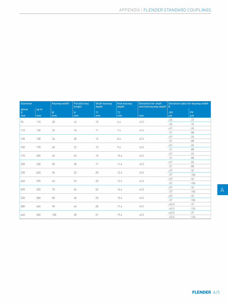
Diameter Keyway width Parallel key height
Shaft keyway depth
Hub keyway depth
Deviation for shaft and hub keyway depth
Deviation table for keyway width B
above up toD B H T1 T2 JS9 P9mm mm mm mm mm mm mm µm µm
95 110 28 16 10 6.4 +0.2+26 -22-26 -74
110 130 32 18 11 7.4 +0.2+31 -26-31 -88
130 150 36 20 12 8.4 +0.3+31 -26-31 -88
150 170 40 22 13 9.4 +0.3+31 -26-31 -88
170 200 45 25 15 10.4 +0.3+31 -26-31 -88
200 230 50 28 17 11.4 +0.3+31 -26-31 -88
230 260 56 32 20 12.4 +0.3+37 -32-37 -106
260 290 63 32 20 12.4 +0.3+37 -32-37 -106
290 330 70 36 22 14.4 +0.3+37 -32-37 -106
330 380 80 40 25 15.4 +0.3+37 -32-37 -106
380 440 90 45 28 17.4 +0.3+43.5 -37-43.5 -124
440 500 100 50 31 19.4 +0.3+43.5 -37-43.5 -124
A/5
E E
4 4
5 5
6 6
7 7
8 8
9 9
10 10
11 11
12 12
13 13
A A
APPENDIX | FLENDER STANDARD COUPLINGS

Torsionally Rigid Couplings
FLE 10.1FLEX-C10001-00-7600
ARPEX High Performance Couplings MD 10.2PDMD-C10146-00
Flexible Couplings
FLE 10.2FLEX-C10002-00-7600
SIPEX and BIPEX-S Backlash-free couplings MD 10.3PDMD-C10145-00
Highly Flexible Couplings
FLE 10.3FLEX-C10003-00-7600
ARPEX Composite Couplings MD 10.5PDMD-C10153-00
Fluid Couplings
FLE 10.4FLEX-C10004-00-7600
ARPEX Safety couplingsMD 10.11PDMD-C10147-00
RELATED CATALOGS
A/6
E E
4 4
5 5
6 6
7 7
8 8
9 9
10 10
11 11
12 12
13 13
A A
FLENDER STANDARD COUPLINGS | APPENDIX
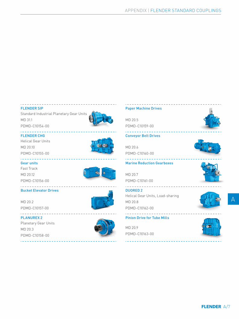
FLENDER SIP Standard Industrial Planetary Gear UnitsMD 31.1PDMD-C10154-00
Paper Machine Drives
MD 20.5PDMD-C10159-00
FLENDER CHG Helical Gear UnitsMD 20.10PDMD-C10155-00
Conveyor Belt Drives
MD 20.6PDMD-C10160-00
Gear units Fast TrackMD 20.12PDMD-C10156-00
Marine Reduction Gearboxes
MD 20.7PDMD-C10161-00
Bucket Elevator Drives
MD 20.2PDMD-C10157-00
DUORED 2 Helical Gear Units, Load-sharingMD 20.8PDMD-C10162-00
PLANUREX 2 Planetary Gear UnitsMD 20.3PDMD-C10158-00
Pinion Drive for Tube Mills
MD 20.9PDMD-C10163-00
A/7
E E
4 4
5 5
6 6
7 7
8 8
9 9
10 10
11 11
12 12
13 13
A A
APPENDIX | FLENDER STANDARD COUPLINGS
A/8
THE RIGHT GEAR UNIT SOLUTION FOR ANY REQUIREMENTWe provide helical and planetary gear units made up of standard modules or as a complete application solution.
Helical and planetary gear units from Flender are modern drive solutions that satisfy the most varying and extreme demands, day after day and year after year. For decades, plant operators have been achieving high system reliability and low lifecycle costs in every conceivable industry with our helical gear units.

Planetary Gear UnitsWith Flender planetary gear units, we provide a range of durable, reliable and finely graduated gear unit solutions. The series wins customers over due to its highly integrated planetary geared motor and maximum conformity with all international motor standards. It also brings quality and performance in a good ratio of lifecycle costs to price.Rated torque: 10,000 Nm … 5,450,000 Nm
Helical and bevel helical gear unitsFlender helical and bevel helical gear units are by far the most comprehensive range of industrial gear units in the world. It ranges from a multi-faceted universal gear unit portfolio and application-specific gear units to customer-specific solutions. Rated torque: 3,300 Nm … 1,400,000 Nm
Application-specific gear unitsWith application-specific gear units, Flender provides by far the most application solutions and thus covers nearly every drive-related need from hundreds of applications in industry and the acquisition of raw materials.Rated torque: up to 10,000,000 Nm
Customer-specific designsOur experts are available at any time for special requirements during the development of new products. From designing and simulating complex drive solutions to implementing them, we work together with you to resolve multi-layered tasks.
SUITABLE GEAR SOLUTIONS
A/9
E E
4 4
5 5
6 6
7 7
8 8
9 9
10 10
11 11
12 12
13 13
A A
APPENDIX | FLENDER STANDARD COUPLINGS

FLENDER COUPLINGS CATALOG FLE 10.3 EDITION 2020 EN
flender.com
Further information on the subject of couplings:flender.com/couplings
Further information on the subject of applications:flender.com/application-specific-gear-unit
For further information on gears:flender.com/gearunits
Further information on the subject of service:flender.com/services
Flender GmbHAlfred-Flender-Straße 7746395 BocholtGermany
Article no.: FLEX-C10003-00-7600
The information given in this product catalog includes descriptions and performance features that in specific applications do not always apply in the form described or may change through further-development of the products. The desired performance features are binding only if they are expressly agreed on conclusion of contract. Subject to availability for delivery and to technical changes.
flender.com