Embed Size (px)
Citation preview

482
SLC40 Series Combination Display LightsHighly bright “Super LED” unit improves visibility and safety.• Eight types of illumination faces in 40mm
size.• Extensible window ensures high visibility
when installed at high places (except C, L, G).
• Super bright Super LED.• The fingersafe spring-up terminals save
wiring time and prevent electrical shocks.• The insulated jumper, when used on
fingersafe spring-up terminals, eliminates the need of terminal cover.
• Legends can be engraved on the attached marking plate. One or two thin marking sheets (not attached) can also be installed (Type F only).
• Spot illumination available for easy recognition in bright environment (Type F only).
• UL and c-UL recognized, EN compliant (EN60947-5-1).
Type F Type C Type L Type V Type GType F(spot illumination)
Type H
An Example of 12-window size
Except for DC-DC converter and resistor types.
LED Illumination
LED Unit
BA9S/13LED LampFor Type C only
BA9S/13Base Lamp(Dual-lamptype only)
E12/15Base Lamp
Incandescent Illumination
Application Example of Jumpers
• A wide variety of illumination face sizes
Combined construction is availble.
White Screen
Clear Marking Plate
Spot Light Lens
• Type F Window Spot Illumination Kit
• Frame (metal)
• Choice of LED or incandescent illumination
• Split-window type reduces installationspace.
Extensible windows
• Available up to 126 windowsLED: 7 rows by 24 columnsLED illumination: 12, 24V AC/DC
The Fingersafe Spring-up terminals reduce wiring time.The integrated terminal cover and insulated jumpers prevent electic shocks.
•
1 2 3 4 5 6 7 8 9 10 11 12 13 14 15 16 17 18 19 20 21 22 23 24
1
2
3
4
5
6
7
Rows
Columns
Maximum Number of Windows for Incandescent Type
Maximum Number of Windows for LED Type
Type F: 40H × 40W mm (Basic size)Type C: 20H × 40W mm × 2 (Split-window type)Type H: 40H × 80W mmType L: 40H × 120W mmType V: 80H × 40W mmType G: 80H × 80W mm
The frame cover and frame are integrated and molded of resin for Type F, one-window type.
Easy to recognize at high places (except Type C, L, and G)
• For LED illuminated 110/220V AC type, up to 60 windows (Type F equivalent) can be mounted.
• For incandescent illuminated 110/220V AC type, up to 50 windows (Type F equivalent) can be mounted. For Type C, up to 105 windows (Type F equivalent) can be mounted.
• Lighting limitations should be considered in any applications.For details, see page 499.

ControlUnits
Display Lights
DisplayUnits
SafetyProducts
TerminalBlocks
Comm.Terminals
AS-Interface
Relays & Timers
Sockets
Circuit Protectors
Power Supplies
PLCs & SmartRelay
Operator Interfaces
Sensors
Control Stations
Explosion Protection
References
FlushSilhouette
SLC40 Series Combination Display Lights
483
Configuration
(H)
(V)
(L)
(C)(C)
(F)
(H)
LED Illuminated (except for Type C)
• Marking plates include clear marking plate, white screen, color screen, lambda converter, and white marking plate with black coating.
• The order to insert clear marking plate, color screen, and white screen can be interchanged if necessary.
• Markings can be engraved on clear marking plate, white screen, and color screen. Engrave markings on the flat surface of the plate or screen next to the lens.
Note: For white marking plate with black coating, engrave a reverse legend on the black-coated surface.
Item Lens Marking Plate(Color Screen) x 2
Display Color
When lamp is off. When lamp is on.
ClearLens
White displaywhen lamp is off.
Clear
White Clear White Specified Color
Color displaywhen lamp is off.
Color Screen(use clearscreen for white)
White Specified Color Specified Color
LambdaConverter White Lambda
Converter White Pure White
Gray Lens GrayWhite marking plate with black coating (Note)
Clear Gray Specified Colorfor legend
LED Illuminated IncandescentIlluminated
• See page 501 for the combination of illumination windows.
LED Illuminated Incandescent Illuminated
• Mounting ClipSLC-3K1 (supplied)
• Frame CoverBlack (B)
• LED Lamp (for Type C only, BA9S/13 base)Illumination Color: Amber, blue, green, red, white, yellow(2 lamps for 1 window equivalent to Type F)
• LED UnitIllumination Color: Amber, blue, green, red, white, yellow, red/green alternate
Incandescent Lamp(BA9S/13 base)(dual lamp type only)
Type F Type C Type H Type L Type V Type G
Illumination Face Types
LED Illuminated Incandescent Illuminated
Incandescent Illuminated and LED Illuminated Type C
• The order to insert clear marking plate, color screen, and white screen can be interchanged if necessary.
• Markings can be engraved on clear marking plate, white screen, and color screen. Engrave markings on the flat surface of the plate or screen next to the lens.
Note: For white marking plate with black coating, engrave a reverse legend on the black-coated surface.
Item Lens Marking Plate(Color Screen) x 2
Display Color
When lamp is off. When lamp is on.
ClearLens
White displaywhen lamp is off.
Clear White Color Screen(use clearscreen for white)
White
Specified Color
Gray GrayWhite markingplate with blackcoating (Note)
Specified Color for Legend
• Lens (acrylic)
• Marking Plate (acrylic)(clear, white, color)
• Lens Frame (plastic)
• Lens (acrylic)
• Marking Plate (acrylic)(clear, white, color)
• Lens Frame (plastic)
• See page 501 for details about lens combination.
Combiation Example of 12 Windows
Spot Illumination(LED illuminated only)
Incandescent Lamp(E12/15 base)
• The illustration above shows combination examples of windows. One-window type is available in Type F.
•••• One-color full •••• One-color full •••• One-color full •••• Two-color Alternate
•••• One-color full •••• One-color full •••• One-color full
(w/check terminal)
12, 24V AC/DC24V DC(Except Type C)
24V DC(Type F only)
24V DC(Except Type C)
100/110V DC (Resistor type)(Except Type C)
100/110V, 200/220V AC(Except Type C)
110V DC (DC-DC Converter Type)(Except Type C)
(Flasher)•••• One-color full
•••• One-color full
•••• One-color full
6, 12, 18, 24V AC/DC(Except Type C)
100/110, 200/220V AC(Except Type C)
(Except Type C)
(Resistor type)
•••• One-color full(w/check terminal)
6, 12, 18, 24V DC(Except Type C)
110V AC/DC

SLC40 Series Combination Display Lights
484
Specifications (SLC40 Series)• LED Illuminated
Specify a color code in place of ∗.Note 1: The rated voltage for w/check terminal type is 24V DC only. Note 4: Including pure white.Note 2: Terminal cover is available (see page 493). Note 5: No freezingNote 3: 50/60Hz with AC voltage type. Note 6: Multiple flasher type units do not synchronize with each other.
• Incandescent Illuminated
Note 1: 50/60Hz with AC voltage type. Note 3: Check terminal type is for DC input only.Note 2: Terminal cover is available for all incandescent illuminated types (see page 493), except for the resistor type.
• LED/Incandescent Illuminated
Note 1: Flasher type, one-window type, pure white illumination, and spot illumination types are available in Type F only.
Light Source LED Unit LED Lamp
Input Type Full Voltage Transformer DC-DC Converter
Resistor Full Voltage
Illumination TypeOne-color
One-color w/check terminal (Note 1)
Two-color Alternate Flasher Type One-color One-color One-color One-color × 2
Split-window Type (Type C)
Fingersafe Spring-up Terminal
Provided(except for check terminal)
—(Note 2) Provided —
(Note 2)
Rated Voltage (Note 3) 12V AC/DC±10%
24V AC/DC±10% 24V DC ±10% 24V DC ±10%
100/110V AC±10%
200/220V AC±10%
110V DC(90 to 140V
DC)
100/110V AC/DC±10%
6V AC/DC ±10%
12V AC/DC±10%
24V AC/DC±10%
Maximum Current Draw (VA) Same as internal LED unit — 4.7 1.8 2.4 Same as internal LED lamp
Illumination Color Amber, blue, green, pure white, red, white, yellow
Red/green Alternate Amber, blue, green, pure white, red, white, yellow Amber, blue, green,
red, white, yellow
Standards UL, c-UL listed, EN compliant — —
Bui
lt-in
LE
D U
nit/L
amp
Rated Voltage 12V AC/DC 24V AC/DC 24V AC/DC 24V AC/DC 6V AC/DC 12V AC/DC 24V AC/DC
Rat
ed C
urre
nt
Amber 40 mA 21 mA
Red: 23 mAGreen: 21 mA
21 mA 20 mA
10 mA 10 mA
Blue 40 mA (Note 4) 21 mA (Note 4) 21 mA (Note 4) 10 mA
Green 32 mA 17 mA 17 mA 10 mA
Red 44 mA 23 mA 23 mA 20 mA
White 44 mA 23 mA 23 mA 20 mA
Yellow 44 mA 23 mA 23 mA 20 mA
Illumination Color (code)
Amber (A), blue (S), green (G), red (R), white (W), yellow (Y)
Red (R)/green (G) Amber (A), blue (S), green (G), red (R), white (W), yellow (Y) Amber (A), blue (S), green (G),
red (R), white (W), yellow (Y)
Base Plug-in unit type (for SLC40 only) BA9S/13 base
Type No. (See page 496) SLCN-2ET-∗ LSTD-6∗ LSTD-1∗ LSTD-2∗
No. of Units 1 LED unit per window of basic Type F 1 LED lamp per window of basic Type F
Flashing Period —0.5 ±0.2s
(fixed duty 1:1)(Note 6)
— —
Insulation Resistance 100 MΩ (500V DC megger)
Dielectric Strength 2000V AC (1 minute)between live and dead parts
2500V AC (1 minute)between live and dead parts
2000V AC(1 minute)
2000V AC (1 minute)between live and dead parts
Operating Temperature –20 to +40°C –10 to +40°C –20 to +40°C –10 to +40°C –20 to +40°C –20 to +40°C
Operating Humidity 45 to 85% RH (no condensation)
Input Type Full Voltage Transformer Resistor
Illumination Type One-colorOne-color w/Check Terminal (Note 3)
One-colorDual-lamp Type One-color
Rated Voltage 6V AC/DC 12V AC/DC 18V AC/DC 24V AC/DC 6V AC/DC 12V AC/DC 18V AC/DC 24V AC/DC 100/110, 200/220V AC 110V AC/DC
Standards —
Bui
lt-in
Lam
p
Rated Voltage 6.3V·2W 18V·2W 24V·2W 30V·2W 6.3V·1W 18V·1W 24V·1W 30V·1W 18V·2W
Operating Voltage 5 to 6V 12 to 18V 18 to 24V 24 to 30V 5 to 6V 12 to 18V 18 to 24V 24 to 30V 12 to 18V
Base E12/15 BA9S/13 E12/15
Type No. LE-6 LE-8 LE-2 LE-3 LS-6 LS-8 LS-2 LS-3 LE-8
No. of Units 1 lamp per window of basic Type F 2 lamps per window of basic Type F 1 lamp per window of basic Type F
Insulation Voltage 100 MΩ (500V DC megger) between live and dead parts
Dielectric Strength 2000V AC (1 minute) between live and dead parts2500V AC (1 minute)
between live and dead parts
2000V AC (1 minute)between live and dead
parts
Operating Temperature –20 to +40°C
Operating Humidity 45 to 85% RH (no condensation) between live and dead parts
Illumination Face Type Type F (Note 1)(Basic Type)
Type C(Split-window Type) Type H Type L Type V Type G
Illu
min
atio
n U
nit
Siz
e (m
m)
Window (H × W) 40 × 40 20 × 40 40 × 80 40 × 120 80 × 40 80 × 80
Illumination Face (H × W) 37 × 37 17 × 37 37 × 77 37 × 117 77 × 37 77 × 77
White color screen,clear marking plate,color screen (H × W × t)
35.8 × 35.8 × 1.0 15.8 × 35.8 × 1.0 35.8 × 75.8 × 1.0 35.8 × 115.8 × 1.0 75.8 × 35.8 × 1.0 75.8 × 75.8 × 1.0
Marking Film Applicable — — — — —
Engraving Area (white, transparent, color plates) 34 × 34 14 × 34 34 × 74 34 × 114 74 × 34 74 × 74
Material of Marking Plate & Color Screen Acrylic
Lens Frame Color & Frame Cover Color Black (Munsell N1.5 equivalent)
Connection Wire Solid wire: ø1.6 × 2, Stranded 2 mm2 × 2
Terminal Screw M3.5 screw, Incandescent resistor: M4 nut, Check terminal: M3
Degree of Protection IP40
Pollution Degree 3

ControlUnits
Display Lights
DisplayUnits
SafetyProducts
TerminalBlocks
Comm.Terminals
AS-Interface
Relays & Timers
Sockets
Circuit Protectors
Power Supplies
PLCs & SmartRelay
Operator Interfaces
Sensors
Control Stations
Explosion Protection
References
FlushSilhouette
SLC40 Series Combination Display Lights
485
Dimensions (SLC40 Series)
• Type F Dimensions & No. of Windows (Type C, H, L, V, and G can be converted into Type F.)
Columns b 01 02 03 04 05 06 07 08 09 10 11 12 13 14 15 16 17 18 19 20 21 22 23 24
Rows Dimensions B 56 96 136 176 216 256 296 336 376 416 456 496 536 576 616 656 696 736 776 816 856 896 936 976
a APanel
Cut-out (D) (45) (85) (125) (165) (205) (245) (285) (325) (365) (405) (445) (485) (525) (565) (605) (645) (685) (725) (765) (805) (845) (885) (925) (965)
(C)
01 56 (45) 1 2 3 4 5 6 7 8 9 10 11 12 13 14 15 16 17 18 19 20 21 22 23 24
02 96 (85) 2 4 6 8 10 12 14 16 18 20 22 24 26 28 30 32 34 36 38 40 42 44 46 48
03 136 (125) 3 6 9 12 15 18 21 24 27 30 33 36 39 42 45 48 51 54 57 60 63 66 69 72
04 176 (165) 4 8 12 16 20 24 28 32 36 40 44 48 52 56 60 64 68 72 76 80 84 88 92 96
05 216 (205) 5 10 15 20 25 30 35 40 45 50 55 60 65 70 75 80 85 90 95 100 105 110 115 120
06 256 (245) 6 12 18 24 30 36 42 48 54 60 66 72 78 84 90 96 102 108 114 120 — — — —
07 296 (285) 7 14 21 28 35 42 49 56 63 70 77 84 91 98 105 112 119 126 — — — — — —
28 40 40
40
4880
80
48 80
2840
40
40
80
68 120
2840
40
40
120
28 40 40
40
2020
1820
20
80
80
80
48
48 80
40
28 40 40
A =
(40
a +
16)
A =
(40
a +
16)
A =
(80
a +
16)
A =
(40
a +
16)
A =
(40
a +
16)
A =
(80
+ 1
6)
2840
40
40
11 Spot Illumination
8.4
B = (40b + 16)
B = (120b + 16)B = (80b + 16)
B = (40b + 16)
B = (40b + 16)B = (80b + 16)
[Front View] a: No. of Rows b: No. of Columns
•••• Type F Spot Illumination •••• Type H •••• Type V
•••• Type L •••• Type G •••• Type C
All dimensions in mm.
12
34 5 6
1
2
3
F
F
H
F F F
L
H
V V
H
1. The number of windows equals rows multiplied by columns. For example, for 5 rows by7 columns, the number of windows is 35, external dimensions are 216mm high by 296mm wide, and panel cut-out is 205mm high by 285mm wide.
2. External dimensions are represented by A for rows and B for columns in boldface.3. Panel cut-out dimensions are shown in ( ), for height (C) and width (D). Panel cut-out
tolerance is +1.0 to –0 mm (for one window: +0.6 to –0.4mm).
How to Read the TablePanel Cut-out (SLC40)
D
C
Determine the panel thickness in consideration of the weight of display lights and wires (see page 493).
4. Total number of windows, dimensions, panel cut-out➀ For Type C, H, L, V, and G, convert the numbers of rows
and columns into Type F (basic size) equivalents.
• Type C — Type F equivalent: 2 split-windows consistsof one window.
• Type H — Type F equivalent: 2 windows
• Type V — Type F equivalent: 2 windows.
➁ The combination example at left consists of 3 rows by 6 columns.
➂ The above table shows: No. of windows: 18Dimensions: 136H × 256W mmPanel cut-out: 125H × 245W mm
Height: 1 rowWidth: 2 columns
Height: 2 rowsWidth: 1 column
• Type L — Type F equivalent: 3 windows
• Type G — Type F equivalent: 4 windows
Height: 1 rowWidth: 3 columns
Height: 2 rowsWidth: 2 columns

SLC40 Series Combination Display Lights
486
Dimensions (SLC40 Series)LED Illuminated [Side & Rear Views]
40669
.9
Pan
el T
hick
ness
0.8
to 6
40
1140
19
X1
X2 X2
X1
X1
X2 X2
X1
M3.5Terminal Screws
40673
Pan
el T
hick
ness
0.8
to 6
X1X1
X2 X2
CC
X1X1
X2 X2
CC
8.3 5.5 40
19
40
M3 Check Terminal
M3.5 Terminal Screws
40687
.5
40
19
40
X1
X2
X1
X2
X1
X2
X1
X2
11
Pan
el T
hick
ness
0.
8 to
6
M3.5Terminal Screws
87.5
6
1140
1940
X2
X1
X2
X1
X2
X1
X2
X1
X2 X2
X1 X1
SLC-3K1
M3.5Terminal Screws
Pan
el T
hick
ness
0.8
to 6
9.2
40
40 11
20
40666
.5
Pan
el T
hick
ness
0.8
to 6
M3.5 Terminal Screws
• Full Voltage Type • 12, 24V AC/DC• One-color full• For applicable terminal cover,
see page 493.
• Full Voltage Type• One-color full• w/Check Terminal 24V DC• Two-color alternate 24V AC/DC• For applicable terminal cover, see page 493.
• Full Voltage Type• One-color full• Flasher Type 24V DC (Type F only)• For applicable terminal cover, see page
493.
• w/Check Terminal TypeTerminal X1 is a positive pole; Terminal X2 and C (check terminal) are negative poles.
• Two-color Alternate TypeTerminal X1 is common.Red (R) illumination: Terminal CGreen (G) illumination: Terminal X2
• Terminals X1 and X2 are positive and negative poles, respectively.
• Transformer Type• One-color full• 100/110, 200/220V AC• 110VDC (DC-DC Converter) Type
• Resistor Type• One-color full• 100/110V AC/DC
•••• Type C• Full Voltage Type• 6, 12, 24V AC/DC• One-color full, 2 × LED lamps,
Split-window type
• Terminal X1 is COM terminal.• For applicable terminal cover, see page 493.
• On LED illuminated DC-DC Converter type units, Terminals X1 and X2 are positive and negative poles, respectively.
All dimensions in mm.
40685
Pan
el T
hick
ness
0.8
to 6
X1X1
X2 X2
X2 X2
X1 X1
1140
2040
M3.5Terminal Screws
ControlUnits
Display Lights
DisplayUnits
SafetyProducts
TerminalBlocks
Comm.Terminals
AS-Interface
Relays & Timers
Sockets
Circuit Protectors
Power Supplies
PLCs & SmartRelay
Operator Interfaces
Sensors
Control Stations
Explosion Protection
References
FlushSilhouette
SLC40 Series Combination Display Lights
487
Incandescent Illuminated [Side & Rear Views]64
.5
Pan
el T
hick
ness
0.8
to 6
40
M3.5Terminal Screw
6
11
40
20
40
Pan
el T
hick
ness
0.8
to 6
X1
X2
X1
X2
X1
X2
X1C
CC
C
X2
4068.3 5.5 40
M3 Check Terminal
M3.5 Terminal Screws19
40
72
PowerPower
M4 Terminal Screws
40
6
14
40
14
40
180
Pan
el T
hick
ness
0.8
to 6
Pan
el T
hick
ness
0.8
to 6
6
6
408588
SLC-3K1
40
11
HW-VL3
M3.5Terminal Screws
20
40666
.540
11
40M3.5Terminal Screw
Pan
el T
hick
ness
0.8
to 6
•••• Type F
• Full Voltage Type• 6, 12, 18, 24V AC/DC• One-color full• For applicable terminal cover,
see page 493.
• Full Voltage Type• One-color full• w/Check Terminal• 6, 12, 24V DC• For applicable terminal cover,
see page 493.
• Resistor Type• 100/110V AC/DC• One-color full
• The dimension of incandescent illuminated 100/110, 200/220V AC is the same as LED illuminated flasher type.
• Full Voltage Type• 6, 12, 18, 24V AC/DC• One-color full• For applicable terminal cover,
see page 493.
• Transformer Type• 100/110, 200/220V AC• One-color full
ResistanceIncandescent: 1kΩ, 40W
All dimensions in mm.
• Incandescent illuminated w/check terminalTerminal X1 and C are positive poles;Terminal X2 is a negative pole.

SLC40 Series Combination Display Lights
488
Dimensions (SLC40 Series)LED Illuminated [One-window, Type F only]
• Full Voltage 6, 12, 24V AC/DC, One-color Full
• Full Voltage 24V DC, w/Check Terminal• Two-color Alternate LED Illuminated 24V DC
• Flasher Type 24V DC
• Transformer Type 100/110, 200/220V AC• DC-DC Converter Type 110V DC
• Resistor Type 100/110V AC/DC
45
45
Tolerance: +0.6, –0.4mm
• w/Check Terminal TypeTerminal X1 is a positive pole; Terminals X2 and C (check terminal) are negative poles.
• Two-color Alternate TypeRed (R) illumination: X1, CGreen (G) illumination: X1, X2
• See page 493 for applicable terminal covers.
• On LED illuminated flasher type, Terminals X1 and X2 are positive and negative poles, respectively.
• See page 493 for applicable terminal covers.
• On LED illuminated DC-DC converter type, Terminals X1 and X2 are positive and negative poles, respectively.
(Resistance)
LED illuminated type: 4.4 kΩ, 3W
All dimensions in mm.
56 6 69.9 11
40 19
Panel Thickness 0.8 to 6 Mounting Clip SLC-3K1
M3.5 Terminal Screws
56 6 73 8.3 5.5
40 19
M3.5 Terminal Screws
M3 Check Terminal
Panel Thickness 0.8 to 6
Mounting Clip SLC-3K1
85 1156 6
2040
M3.5 Terminal Screws
Panel Thickness 0.8 to 6 Mounting Clip SLC-3K1
56 6 87.5 11
40 19
Mounting Clip SLC-3K1
M3.5 Terminal Screws
Panel Thickness 0.8 to 6
6 87.5 11
19
56
40
M3.5 Terminal Screws
Panel Thickness 0.8 to 6 Mounting Clip SLC-3K1
ControlUnits
Display Lights
DisplayUnits
SafetyProducts
TerminalBlocks
Comm.Terminals
AS-Interface
Relays & Timers
Sockets
Circuit Protectors
Power Supplies
PLCs & SmartRelay
Operator Interfaces
Sensors
Control Stations
Explosion Protection
References
FlushSilhouette
SLC40 Series Combination Display Lights
489
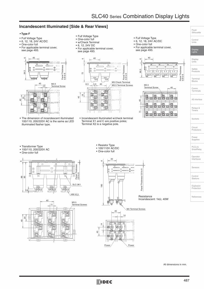
Incandescent Illuminated [One-window, Type F only] (SLC40 Series)• Full Voltage 6, 12, 24V AC/DC, One-color Full
• Full Voltage 24V DC, w/Check Terminal, One-color Full
• Transformer Type 100/110, 200/220V AC, One-color Full
• Resistor Type 100/110V AC/DC, One-color Full
• Full Voltage 6, 12, 24V AC/DC, One-color Full (Dual-lamp Type)
45
45
Tolerance: +0.6, –0.4mm
• w/Check Terminal TypeTerminal X1is a positive pole; Terminal X2 and C (check terminal) are negative poles.
• For applicable terminal cover, see page 493.
• For applicable terminal cover, see page 493.
• On dual-lamp type, Terminal X1 is a common terminal. Terminals X1 and X2 are interconnected.
• For applicable terminal cover, see page 493.
(Resistance)
Incandescent: 1 kΩ, 40W
All dimensions in mm.
64.5 1156 6
2040
M3.5 Terminal Screws
Panel Thickness 0.8 to 6 Mounting Clip SLC-3K1
56 6 72 8.3 5.5
40 19
M3.5 Terminal Screws
M3 Terminal Screws
Panel Thickness 0.8 to 6
Mounting Clip SLC-3K1
85 1156 6
2040
M3.5 Terminal Screws
Panel Thickness 0.8 to 6 Mounting Clip SLC-3K1
56 6 180
40
14
Mounting Clip SLC-3K1
M4 Terminal ScrewsPower Supply
M4 Terminal ScrewsPower Supply
Panel Thickness 0.8 to 6
9.266.556 6
40 11
20
M3.5 Terminal Screws
Panel Thickness 0.8 to 6 Mounting Clip SLC-3K1

SLC40 Series Combination Display Lights
490
Terminal Connection (LED Illuminated)• For check terminal type, DC-DC converter type, and resistor
type, Terminals X1 and X2 are positive and negative poles, respectively.
(Flasher Type Connection Diagram)
• For w/check terminal and two-color alternate type units, Terminal X1 is a positive pole; Terminals X2 and C (check terminal) are negative poles. For two-color alternate type, Terminal X1 is common.
• Connection for Two-color alternate type is as follows.Terminal X1 is common (AC/DC).Red (R):Terminal CGreen (G):Terminal X2
• For the LED illuminated split-window type (Type C), Terminal X1 is a common terminal. Terminal X2 is for upper illumination and Terminal X3 is for lower illumination (AC/DC).
Terminal Connection Using Jumpers• For terminal connection of types F, H, L, V, and G (except Type
C) using jumpers, jumpers can be used as shown below.
SLC40 Series
Note 1: Fingersafe, spring-up terminals are used in one-color full illuminated type (12, 24V AC/DC, 100/110, 200/220V AC, 110V DC).
Note 2: No jumper is used on resistor type.
• For Type C, jumpers can be used on Terminal X1 only as shown below.
Note: Jumpers cannot be used when using Type C and fingersafe spring-up terminals.
Terminal Connection(Incandescent Illuminated)• For incandescent illuminated dual-lamp type, terminal X1 is a
common terminal. Terminals X2 and X3 are connected with jumpers.
• The incandescent illuminated check terminal type is for DC voltage only. Terminal X1 is a positive pole, and terminal X2 is a negative pole. Check terminal is a positive pole.
• Wiring direction for incandescent illuminated check terminals is the same as that of LED illuminated type.
[Examples of Using Jumpers]LED Illuminated (fingersafe Spring-up Terminal)
Arrows indicate access direction for wiring terminals.
Fingersafe, Spring-up Terminal
Other terminals
LED Module
FlasherCircuit
X1
Positive
NegativeX2
X1
X2
C (w/Check Terminal Type Connection Diagram)
X1Positive
Negative
Negative
C
X2
LEDModule
Arrows indicate access directions for wiring terminals.
X1Common
CRed (R)
X2Green (G)
LED Module
Positive
Negative
Negative
(Two-color alternate Type Connection Diagram)
X2
X3
X1
Arrows indicate access direction for wiring terminals.
Recommended tightening torque:M3.5: 1 to 1.3 N·mM3: 0.6 to 1.0 N·m
Terminal X1 Terminal X2 Terminal C
LEDIlluminated(Note 2)
Fingersafe,Spring-upTerminal(Note 1)
SLCN-JP44SLCN-JP45
SLCN-JP44SLCN-JP45 —
Others SLC-JP40 SLC-JP41 SLC-JP42
Incandescent Illuminated SLC-JP40 SLC-JP41 SLC-JP42
Direction• When using Type C only• When using Type C and Two-color alternate
Vertical SLC-JP40
Horizontal SLC-JP41
Using one SLCN-JP45 jumper
Using two SLCN-JP45 jumpersWhen using three windows
Using one SLCN-JP44 jumperWhen using four windows
When using two windows
Jumpers (SLCN-JP44/45) have an orientation.Ensure that jumpers are installed correctly.
Correct Incorrect

ControlUnits
Display Lights
DisplayUnits
SafetyProducts
TerminalBlocks
Comm.Terminals
AS-Interface
Relays & Timers
Sockets
Circuit Protectors
Power Supplies
PLCs & SmartRelay
Operator Interfaces
Sensors
Control Stations
Explosion Protection
References
FlushSilhouette
SLC40 Series Combination Display Lights
491
Type No. Development (SLC40 Series)
The following color/voltage selections are also available.
Unit Type (Code)Operating Voltage (Built-in Lamp)
(Code)
LED
Illu
min
ated LE
D U
nit
Full Voltage w/Check Terminal Type(PW, S)
DHMA 24V AC/DC ±10% 2
Full Voltage Flasher Type(PW, S)
DFA 24V AC/DC ±10% 2
Transformer Type (A, G, R, W, Y) TD
115V AC ±10% 11
120V AC ±10% 12
230V AC ±10% 23
240V AC ±10% 24
380V AC ±10% 38
400/440V AC ±10% 4
480V AC ±10% 48
Transformer Type (PW, S) TDA
115V AC ±10% 11
120V AC ±10% 12
230V AC ±10% 23
240V AC ±10% 24
380V AC ±10% 38
400/440V AC ±10% 4
480V AC ±10% 48
DC-DC Converter Type (PW, S) CDA 110V DC (90 to 140V DC) 1
Resistor Type (PW, S) RNA 100/110V AC/DC ±10% 1
LED
Lam
p
One-color Full window types (Type C)(combination of S only)
BA9S/13Base
DPA
6V AC/DC ±5% (LSTD-6S) × 2 6
12V AC/DC ±10% (LSTD-1S) × 2 1
24V AC/DC ±10% (LSTD-2S) × 2 2
One-color Full window types (Type C)(combination of S andA, G, R, W, Y)
DPC
6V AC/DC ±5% (LSTD-6∗) 6
12V AC/DC ±10% (LSTD-1∗) 1
24V AC/DC ±10% (LSTD-2∗) 2
Inca
ndes
cent
Illum
inat
ed
Transformer Type E12/15Base TE
115V AC ±10% (LE-8) 11
120V AC ±10% (LE-8) 12
230V AC ±10% (LE-8) 23
240V AC ±10% (LE-8) 24
380V AC ±10% (LE-8) 38
400/440V AC ±10% (LE-8) 4
480V AC ±10% (LE-8) 48
Equivalent of Basic Size Windows
Rows Columns
01 01
02 02
03 03
04 04
05 05
06 06
07 07
08
09
10
11
12
13
14
15
16
17
18
19
20
21
22
23
24
SLC40N – 4 0 50 – TD 2 F B
40 Series When ordering Type H, L, V, G, or C units, enter the equivalents of Type F.
Illumination Face Size(Code)
•Type F40 × 40mm
F
•Type H40 × 80mm
H
•Type L40 × 120mm
L
•Type V80 × 40mm
V
•Type V80 × 80mm
G
•Type C(20 × 40mm) × 2
C
•Type MCombination of types F, H, L, V, and C (specify in the ordering sheet)
M
•Type F Spot Illumination40 × 40mm FST
Illumination Color
• Clear Lens Combination (Code)
Amber A
Green G
Red R
Blue S
White W
Yellow Y
• Color Screen Combina-tion (LED only) (Code)
When color display is required at power off, order color screens. For details, see page 501.
Amber TA
Green TG
Red TR
Blue TS
White TW
Yellow TY
•Gray Lens Combination(Code)
Amber SA
Green SG
Red SR
Blue SS
White SW
Yellow SY
•Type H, L, V, and G cannot be split-illuminated.
•Use specification sheet when ordering Type M unit or 2-way split illumination type.
•Enter the required number of color screens in ( ).
• Lambda Converter
Pure White PW
One-color Full Type F only (except spot illumination type)
Frame Color
Black: B
Example: G (5), R (5), W (10) Specify the color code and the number of windows.–
Note: For longer lamp life, LE-3 (30V rating, 2W lamp) or LS-3 (30V rating, 1W) lamps are recommended when using on 24V AC/DC.
Unit Type(Code)
Operating Voltage(Built-in Lamp)
(Code)
LED
Illu
min
ated
LED
Uni
t
Full Voltage Type (A, G, R, W, Y) DD12V AC/DC ±10% 1
24V AC/DC ±10% 2
Full Voltage Type (PW, S) DDA 24V AC/DC ±10% 2
Full Voltage w/Check Terminal Type(A, G, R, W, Y) DHM 24V DC ±10% 2
Full Voltage Two-color Alternate (R/G) DW 24V AC/DC ±10% 2
Full Voltage Flasher Type (A, G, R, W, Y) DF 24V DC ±10% 2
Transformer Type (A, G, R, W, Y) TD100/110V AC ±10% 1
200/220V AC ±10% 2
Transformer (PW, S) TDA100/110V AC ±10% 1
200/220V AC ±10% 2
DC-DC Converter Type (A, G, R, W, Y) CD 110V DC (90 to 140V DC) 1
Resistor Type (A, G, R, W, Y) RN 100/110V AC/DC ±10% 1
LED
Lam
p
One-color Full × 2 split window types (Type C) (A, G, R, W, Y)
BA9S/13Base DP
6V AC/DC ±10% (LSTD-6∗) 6
12V AC/DC ±10% (LSTD-1∗) 1
24V AC/DC ±10% (LSTD-2∗) 2
Inca
ndes
cent
Illu
min
ated
Full Voltage Type
E12/15Base
DE
5 to 6V AC/DC (LE-6) 6
12 to 18V AC/DC (LE-8) 8
18 to 24V AC/DC (LE-2) (Note) 2
24 to 30V AC/DC (LE-3) 3
Transformer Type TE100/110V AC ±10% (LE-8) 1
200/220V AC ±10% (LE-8) 2
Resistor Type RE 100/110V AC/DC ±10% (LE-8) 1
Full Voltage Dual Lamp Type BA9S/13Base DB
5 to 6V AC/DC (LS-6) 6
12 to 18V AC/DC (LS-8) 8
18 to 24V AC/DC (LS-2) (Note) 2
24 to 30V AC/DC (LS-3) 3
Full Voltagew/Check Terminal Type
E12/15Base DEM
5 to 6V DC (LE-6) 6
12 to 18V DC (LE-8) 8
24 to 30V DC (LE-3) 3

SLC40 Series Combination Display Lights
492
Ordering Information (SLC40) [Conversion Rate]
1
1
2
3
4
2 3 4 5
Ex. 1
Ex. 2
Ex. 3
Ex. 4
Type F, 20 windows
Type H, 9 windows (Type F equivalent: 3 rows by 6 columns)
Type M, 8 windows (Type F equivalent: 2 rows by 4 columns)
Incandescent illuminated typewhen arrangement of colorscreen is not designated.
LED illuminated unitsin one color.
SLC40N-
Color screen: Type F, 20 windows
Color screen: Type H, 9 windows
Specify the position and each colorcode on the specification sheet.
G(5) + R(5) + S(5) + Y(5) = 20
G (3) + R (3) + Y (3) = 9
SLC40 Series
04 G(5), R(5), S(5), Y(5) 05 F R (20)
G (9)SLC40N-
SLC40 Series
03 G(3), R(3), Y(3)
No entry is required in designations.
No entry is required in designations.
Specify each color code on thespecification sheet.
Specify each color code on thespecification sheet.
No entry is required in designations.06 H
SLC40 Series (Type F, 12 windows)
When ordering a combination of units with different operating voltages, specify Type No. as follows.
Specify the position of the units and each voltage on the specificaiton sheet.
24V AC/DC 100/110V AC 48 Transformer Type
Color screen: Type H, 9 windowsG (9) = 9
SLC40N-
SLC40 Series
02 04 M
SLC40N-0304- DD 2 FB(8)+ TD 1 FB(4)- W(12)
Columns
Columns
Rows
Columns
Rows
Rows
1
2
3
4
5
1 2 3 4 5 6
+ + + + + +
+
+
+
+
Columns
Rows
Columns
Rows
Columns
Rows
Color Code
Color Code
Columns
Rows
Color Code
1
2
3
4
1 2 3 4 5 6W
W
W
R
R
G
R
R
G
+ + + + + +
+
+
+
+
7
1
2
3
1 2 3 4 5W
R W
G
G
+ + + + +
+
+
1
2
3
4
1 2 3 4 5
+
+
++ + + + +
DD2
TD1
Color screen: Type F, 20 windowsR (20) = 20
1
1
2
3
2 3 4 5 6
Ex.Color Code
Color Code
Color Screen Code
Color Screen Code
Ex.
Ex. 5 When ordering a combination of units with diffrent illuminatin colors, specity Type No. as follows.
Specify the position of the unitsand each color code on thespecificaiton sheet.
Example: Full voltage LED illuminated 24V AC/DC, Red (6), Pure White (2) Columns
Rows
Color Code
SLC40N-0204-DD2FB(6) + DDA2FB(2) - R(6)PW(2)Red Pure White Designation
Red: 6, Pure White: 2
1
2
1 2 3 4 5PW R R R
PW R R R
+ + + +
+
+
+
Type F, 12 windows, Full voltage type
• When more than one color is required for LED.
• When a particular arrangement of color screen is required.
• When color screen is required, specify the color screen code.
• When color screen is required, specify the color screen code. R R G G G
Y Y Y Y Y
A A W W W
A A W W W
1
1
2
2 3 4
When ordering SLC Series Combination Display Lights, use the specification sheet provided on page 509.
•••• Designation Procedure1. Type No.: Refer to Type No. Configuration on page 491.2. Quantity: Enter the required number of identical assemblies.
•••• Counting of WindowsCount the number of windows in the equivalent of Type F (basic size).
• Leaf SpringsLeaf spring for temporary fastening is not attached, and can be supplied free of charge upon request when ordering (Type No. SLD40KVP).
• Type H (horizontal type)
• Type L (horizontal type)
• Type V (vertical type)
• Type G (large type)
• Type C (split-window type)
Type F equivalent: 2 windowsRow (1), Column (2)
Type F equivalent: 3 windowsRow (1), Column (3)
Type F equivalent: 2 windowsRow (2), Column (1)
Type F equivalent: 4 windowsRow (2), Column (2)
Type F equivalent: 1 windowRow (1), Column (1)[Designation Examples]