Embed Size (px)
Citation preview

TOYOTA Highlander 2015 LED Fog Light & DRL 2in1
Part Number: 00016-48011 Accessory Code: LD4000 Conflicts
- Vehicles w/o factory Fog Lights
Kit Contents Item # Quantity Reqd. Description 1 2 Fog + DRL Housings 2 1 DRL Driver Box 3 1 DRL Harness Bag 4 1 DRL User’s Card 5 1 DRL Switch
Hardware Bag Contents Item # Quantity Reqd. Description 1 1 Hood Wire harness 2 1 Cabin Wire harness 3 1 Relay 4 25 Wire ties 5 1 14” wire tie 6 2 Black T-Taps 7 1 10mm nut
Additional Items Required For Installation Item # Quantity Reqd. Description
Recommended Tools Safety Tools
Safety Glasses Electrical Tape
Installation Tools 10mm Wrench Phillips Screw Driver Stuby # 2 Pliers Torque Wrench 48 in-lb Side Cutters
Special Chemicals 3M Silicon Sealant
Accessory Service Parts
Service Part
DR
L + Fog Housing LH
DR
L + Fog Housing R
H
DR
L Switch
DR
L Wi re H
arness
DR
L Driver B
ox
DR
L Re lay
Part Number 00016-48011-01 X 00016-48011-02 X 00016-32270-05 X 00016-32270-03 X 00016-32270-06 X 00016-32260-04 X
General Applicability Models:
Recommended Sequence of Application Item # Accessory 1 LED Fog Light 2 Fender Flare 3
Mandatory Legend
SPECIAL NOTE: After TMS and Safety mandated preparatory steps have been taken, the installation sequence is the suggested method for completing the accessory installation. In some instances the suggested sequence is written for one associate to install and in others the sequence is given as part of a team accessory installation. Unless otherwise stated in the document, the associates may perform the installation steps in any order to make the installation as efficient as possible while maintaining consistent quality. Also some items listed to be removed may not need to be removed if caution is taken to not damage vehicle.
Southeast Toyota Distributors, LLC Page 1 of 15
TOYOTA Highlander LED Fog Light & DRL 2in1
Care must be taken when installing this accessory to ensure damage does not occur to the vehicle. The
installation of this accessory should follow approved guidelines to ensure quality installation. These guidelines
can be found in the Accessory Installation Practices document.
This document covers such items as:
• Vehicle Protection (use of covers and blankets, cleaning chemicals, etc)
• Safety (eye protection)
• Vehicle Disassembly / Reassembly (panel removal, part storage, etc)
Preparation
Remove negative battery cable
Installation 1. From front of vehicle, lay the DRL’s wire
harness on the engine compartment, right
side of the battery.
2. Drop the wire harness down towards the
driver’s side fog light area.
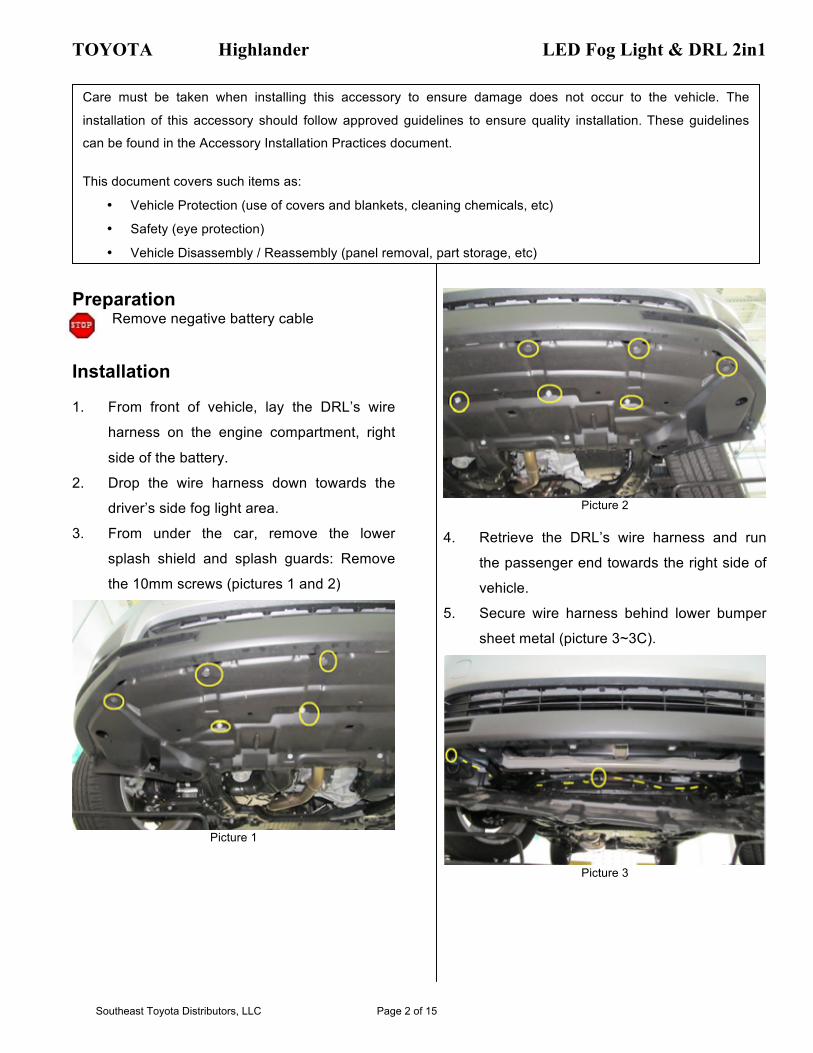
3. From under the car, remove the lower
splash shield and splash guards: Remove
the 10mm screws (pictures 1 and 2)
Picture 1
Picture 2
4. Retrieve the DRL’s wire harness and run
the passenger end towards the right side of
vehicle.
5. Secure wire harness behind lower bumper
sheet metal (picture 3~3C).
Picture 3
Southeast Toyota Distributors, LLC Page 2 of 15

TOYOTA Highlander LED Fog Light & DRL 2in1
Picture 3A
Picture 3B
Picture 3C
6. Unplug passenger side fog lamp (pic. 4)
Picture 4
7. Remove passenger side fog lamp, by
removing 1 factory screw. Reach fog light
housing between bumper and lowered
splash-guard and remove. Note: screws will
be used on installation, do not discard them
(pic. 5~5A).
Picture 5
Picture 5A
Southeast Toyota Distributors, LLC Page 3 of 15

TOYOTA Highlander LED Fog Light & DRL 2in1
Note: If the fog light connector is pre-
installed in the kit, proceed to step 11
8. The factory fog light harness polarity is
shown in picture 6. Pin 1 is negative. Pin2 is
positive
Picture 6: Factory Fog Light harness.
Pin 1: Negative Pin 2: Positive
Picture 6A
9. Push the wires from LED fog light housing
into the supplied connector, to match the
polarity of the factory wire harness (pic. 7).
Picture 22: 2in1 Fog Light wire terminal.
Picture 7A: Showing Fog light terminal connected.
10. Before connecting the LED Fog light, make
sure that wires are aligned as follows
- LED Fog light red (+) with factory blue (+)
- LED Fog Light black (-) with factory white-
black (-)
11. Install the passenger side 2in1 light housing
into the bumper’s plastic sleeve and secure
other side with factory screw. Plug the
factory fog light connector into LED fog light
connector. Then plug the DRL wire harness
connector to the 2in1 DRL connector
(picture 8 and 8A).
Picture 8
Picture 8A
12. At the driver side, turn wheel to the left and
remove the front/lower part of the fender
liner (picture 9)
Southeast Toyota Distributors, LLC Page 4 of 15

TOYOTA Highlander LED Fog Light & DRL 2in1
Picture 9
13. From behind of fender liner, disconnect and
remove the driver’s side factory fog light by
removing 1 factory screw. Lamp can be
removed through the opening of the lowered
fender liner.
14. Then install and connect 2in1 light housing.
15. Secure excess wire from DRL harness with
wire ties at the passenger side
Picture 10
16. Reinstall lower splash shield.
17. Remove top and rear part of the driver’s
side fender liner (picture 11~11A)
Picture 11
Picture 11A
18. Run wire harness from driver’s side fog light
area towards the opening behind the head-
lamp. Reach wire harness from the wheel
well opening (picture 12)
Picture 12
Southeast Toyota Distributors, LLC Page 5 of 15

TOYOTA Highlander LED Fog Light & DRL 2in1
19. From behind wheel liner, retrieve DRL
harness and route towards hood release
cable grommet (following the hood release
cable). Secure with wire ties (pic. 14~14B).
Note: Use the factory white clips to secure
the wire harness.
Picture 14
Picture 14A
Picture 14B
20. Locate the hood-release cable grommet.
Cut the grommet and push the red, black,
black-white and red-white wires through
firewall. Note: Extra caution should be taken
not to damage the connector’s pin. Secure
wire with a wire tie and then seal with 3M
Silicone sealant (picture 15~15A)
Picture 15
Picture 15A
Southeast Toyota Distributors, LLC Page 6 of 15

TOYOTA Highlander LED Fog Light & DRL 2in1
21. Secure DRL harness behind wheel well
area with wire ties.
22. Reinstall fender liner.
Vehicle Disassembly
23. Remove driver side door scuff plate:
Disengage with panel tool and remove
(pic.16)
Picture 16
24. Then, remove the driver side cowl side trim.
Unscrew the cowl side trim clip. Disengage
two (2) clips and remove the cowl side trim
(picture 17)
Picture 17
25. Remove the driver’s side panel. Disengage
with panel tool and remove (picture 18)
Picture 18
26. Remove the driver’s side under cover sub
assembly by removing the 2 screws at the
bottom and disengaging clips of the panel
(picture 19 ~ 19A)
Picture 19
Picture 19A
Southeast Toyota Distributors, LLC Page 7 of 15

TOYOTA Highlander LED Fog Light & DRL 2in1
27. Remove driver side lower dash panel by
removing 1 screw, clips and remove hood
cable. (picture 20~20A)
Picture 20
Picture 20A
28. Locate the wires that were pushed through
the grommet in step 19. Route wire harness
towards the left side of steering wheel. Use
wire ties as needed
29. Push the pins of the DRL wire harness into
the connector supplied in kit. The connector
has a “+” and “–“ marks. So connect the red
wire into the “+” side and black wire into the
“–“ side. You may use the driver box as a
guide: wire colors must be aligned with the
wire colors of the driver box: black with
black and red with red, etc (picture 21)
Picture 21
30. Connect the driver box to the wire harness
(make sure wire colors are aligned).
31. Using a 14” wire tie, secure the driver box to
left side of lowered dash panel. Then use a
regular wire tie to secure lower part of driver
box to dash (pictures 22~22A).
Picture 22
Picture 22A
Southeast Toyota Distributors, LLC Page 8 of 15

TOYOTA Highlander LED Fog Light & DRL 2in1
32. Using the supplied 10 mm nut, secure the
black wire with a ring terminal from DRL
harness to the empty bolt next to the 10mm
nut on top of junction block (picture 23)
Picture 23
33. Install a black T-Tap to connector 4F pin 19,
black wire. Then connect the red wire from
DRL harness to T-tap. Connector 4F is
located at the main junction block. (pictures
24~24C). Connector 4F pin 19 is a 12V
ignition source.
Picture 24
Picture 24A
Picture 24B:
DRL’s red wire to connector 4F, Pin 19, black wire (10A Ignition Fuse No3)
Connector 4F has 3 rows:
1st with 8 pins, middle row: 12 pins and 3rd row 12 pins
Picture 24C
34. Install a black T-Tap to connector IF1, pin 6,
Red wire. Then connect the blue wire from
DRL harness to t-tap. Connector IF1 is
located at the kick panel. Connector IF1 is
the power window control illumination
Southeast Toyota Distributors, LLC Page 9 of 15

TOYOTA Highlander LED Fog Light & DRL 2in1
circuit. IF1 is a gray connector (pictures
25~25B).
Picture 25
Picture 25A
DRL’s blue wire to connector If1, pin 6, red wire (5A panel fuse)
Connector IF1 has 2 rows:
1st with 10 pins and 2nd with 8 pins. It is a gray connector
Picture 25B
35. Secure any excess wire from t-taps, fuse
and relay to main wire harness (picture 26).
Make sure to leave enough lead on the
switch’s green connector.
Picture 26
36. Push out the switch knockout located at the
left of the steering wheel. Route DRL switch
connector through switch knockout.
Connect the switch wire harness to switch,
then mount switch into dash panel (pic 27).
Picture 27
37. Reinstall panels and connectors.
38. Reconnect negative battery terminal.
Torque terminal to 48 in-lbs.
Southeast Toyota Distributors, LLC Page 10 of 15

TOYOTA Highlander LED Fog Light & DRL 2in1
Right: showing LED Fog Light “ON”
Left: Showing DRL “ON”
Fog Light Aiming Traditional fog lights are usually mounted in the
front bumper about 10-24 inches from the ground.
There are two important issues to address when
installing fog lights: the first is to minimize the
amount of return glare into the drivers eyes, and
the other is to minimize the glare into oncoming
eyes. Both of these issues must be accomplished
while putting as much light as possible on the
road.
These fog weather light aiming instructions are
suggestions taken from common practice and the
S.A.E. standard J583. Some modifications to
these instructions may be necessary to minimize
glare.
Visual aim is made with the top of the beam 4
inches below the lamp center at 25 feet with the
lamp facing straight forward (see picture 28)
Picture 28
NOTE: Use only hand tools to adjust the fog light aiming screw. DO NOT use
automatic tools, as they will damage the fog light
Southeast Toyota Distributors, LLC Page 11 of 15

TOYOTA Highlander 2015 - LED Fog Light & DRL 2in
Check System for Operation 1. DRL will work at full power when ignition
switch is ON. DRL will dim out to DOT
specifications when lights are ON.
2. If DRL switch position is off, DRL will not
work at any time.
Check Accessory Functions Checks
DRL function…………………………..
Fog Lights function…………………………..
All Panels snapped into place……………….
Fog Lights………………………………………
Battery Terminal……………………………….
Operation Guide……………………………….
Vehicle Function checks
Check functions all switch functions
Look For:
….
….
- Loose panels and switches
- Visually confirm lights are straightforward
- Re-torque battery terminals to 48 in-lb
- Place DRL operation guide inside glove box.
Checklist – these points MUST be checked to ensure quality installation
Southeast Toyota Distributors, LLC Page 12 of 15

Highlander 2015Ver. 11.28.2014
+12V at connector4F pin19black wire
+12V at connector IF1 pin 6red wire
2
1
2
1
5A
(5A panel fuse)
(10A igntion fuse No.3)
Southeast Toyota Distributors, LLC Page 13 of 15

Pinout'test
Connector'C-1
Pin Wire'Color Test'Reference Proper'Operation
1 Black Pin'1'to'Ground Approximately'0'VDC'
2 Red Pin'2'to'Ground Approximately'0'VDC'ignition'switch'is'OFF''+12'VDC'when''ignition'switch'is'ON
4 RedIWhite Pin'4'to'GroundApproximately'0'VDC'ignition'switch'is'OFF'Approximately'0'VDC'ignition'switch'is'ON,'DRL'switch'is'OFF'+12'VDC'when'ignition'switch'is'ON''and'DRL'switch'is'ON
5 Red Pin'5'to'Ground Approximately'0'VDC'ignition'switch'is'OFF''+12'VDC'when''ignition'switch'is'ON
Connector'C-2,'C-3
Pin Wire'Color Test'Reference Proper'Operation
1 Red'or'RedIWhite Pin'1'to'GroundAproximately'0'VDC'when'igntion'switch'is'OFFAproximately'0'VDC'when'ignition'switch'is'ON,'DRL'switch'is'OFFAproximately'+18'to'+24'VDC'when'ignition'switch'is'ON,'DRL'switch'is'ON
2 Black'or'BlackIWhite Pin'2'to'Ground Aproximately'0'VDC
Connector'C-4
Pin Wire'Color Test'Reference Proper'Operation
1 Black Pin'1'to'Ground Aproximately'0'VDC
2 RedIYellow Pin'2'to'GroundApproximately'0'VDC'ignition'switch'is'OFF'Approximately'0'VDC'ignition'switch'is'ON,'DRL'switch'is'OFF'+12'VDC'when'ignition'switch'is'ON''and'DRL'switch'is'ON
3 Blue Pin'3'to'Ground Aproximately'0'VDC'dash'panel'lights'are'OFF'+12'VDC'when'dash'panel'lights'are'ON
Southeast Toyota Distributors, LLC Page 14 of 15

Connector'C-5FEMALE'TERMINAL'VIEW
Pin Wire'Color Test'Reference Proper'Operation
1 RedIYellow Pin'1'to'GroundApproximately'0'VDC'ignition'switch'is'OFF'Approximately'0'VDC'ignition'switch'is'ON,'DRL'switch'is'OFF'+12'VDC'when'ignition'switch'is'ON''and'DRL'switch'is'ON
2 Red Pin'2'to'Ground Approximately'0'VDC'ignition'switch'is'OFF''+12'VDC'when''ignition'switch'is'ON
3 RedIWhite Pin'3'to'GroundApproximately'0'VDC'ignition'switch'is'OFF'Approximately'0'VDC'ignition'switch'is'ON,'DRL'switch'is'OFF'+12'VDC'when'ignition'switch'is'ON''and'DRL'switch'is'ON
4 Black Pin'3'to'Ground Aproximately'0'VDC
Connector'C-6
Pin Wire'Color Test'Reference Proper'Operation
1 Black Pin'1'to'Ground Aproximately'0'VDC
Connector'C-7
Pin Wire'Color Test'Reference Proper'Operation
1 Red Pin'1'to'Ground Aproximately'0'VDC'when'ignition'switch'is'OFF+12'VDC'when'ignition'switch'is'ON
Connector'C-8
Pin Wire'Color Test'Reference Proper'Operation
1 Blue Pin'1'to'Ground Aproximately'0'VDC'dash'panel'lights'are'OFF'+12'VDC'when'dash'panel'lights'are'ON
Connector'C-9
''''''2''''''''''''''1
Pin Wire'Color Test'Reference Proper'Operation
1 Black Pin'1'to'Ground Aproximately'0'VDC
2 Red Pin'2'to'Ground Approximately'12'VDC'headlamp'switch'is'ON'and'FOG'Light''switch'is'ON'+0'VDC'all'other'times
Southeast Toyota Distributors, LLC Page 15 of 15