Embed Size (px)
Citation preview

High Voltage Cables
5.0 High Voltage Cables High Voltage Cables are used when underground transmission is required. These cables are laid in ducts or may be buried in the ground. Unlike in overhead lines, air does not form part of the insulation, and the conductor must be completely insulated. Thus cables are much more costly than overhead lines. Also, unlike for overhead lines where tappings can easily given, cables must be connected through cable boxes which provide the necessary insulation for the joint. Cables have a much lower inductance than overhead lines due to the lower spacing between conductor and earth, but have a correspondingly higher capacitance, and hence a much higher charging current. High voltage cables are generally single cored, and hence have their separate insulation and mechanical protection by sheaths. In the older paper insulated cables, the sheath was of extruded lead. Figure 5.1 shows three such cables, as usually laid out.
The presence of the sheath introduces certain difficulties as currents are induced in the sheath as well. This is due to fact that the sheaths of the conductors cross the magnetic fields set up by the conductor currents. At all points along the cable, the magnetic field is not the same, Hence different voltages are induced at different points on the sheath. This causes eddy currents to flow in the sheaths. These eddy currents depend mainly on (a) the frequency of operation, (b) the distance between cables, (c) the mean radius of the sheath, and (d) the resistivity of the sheath material.
5.1 Power loss in the Cable
Power loss in the cable can occur due to a variety of reasons (Figure 5.2). They may be caused by the conductor current passing through the resistance of the conductor - conductor loss (also sometimes called the copper loss on account of the fact that conductors were mainly made out of copper), dielectric losses caused by the voltage across the insulation, sheath losses caused by the induced currents in the sheath, and intersheath losses caused by circulating currents in loops formed between sheaths of different phases. The dielectric loss is voltage dependant, while the rest is current dependant.
Figure 5.1 - Layout of three, single-core cables
Heat generated ↑ conductor ↑ ↑ ↑ ↑ ↑ ↑ loss dielectric sheath & intersheath loss loss loss
Figure 5.2 - Heat Transfer in a cable due to losses
High Voltage Cables
5.1.1 Dielectric loss
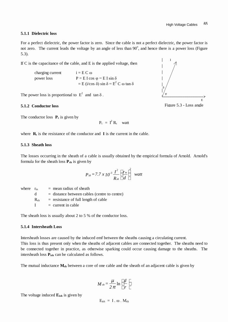
For a perfect dielectric, the power factor is zero. Since the cable is not a perfect dielectric, the power factor is not zero. The current leads the voltage by an angle of less than 90o, and hence there is a power loss (Figure 5.3).
If C is the capacitance of the cable, and E is the applied voltage, then
charging current i = E C power loss P = E I cos = E (i/cos 2 C The power loss is proportional to E2 and tan 5.1.2 Conductor loss The conductor loss Pc is given by Pc = I2 Rc watt where Rc is the resistance of the conductor and I is the current in the cable. 5.1.3 Sheath loss The losses occurring in the sheath of a cable is usually obtained by the empirical formula of Arnold. Arnold's formula for the sheath loss Psh is given by
where rm = mean radius of sheath d = distance between cables (centre to centre) Rsh = resistance of full length of cable I = current in cable The sheath loss is usually about 2 to 5 % of the conductor loss. 5.1.4 Intersheath Loss Intersheath losses are caused by the induced emf between the sheaths causing a circulating current. This loss is thus present only when the sheaths of adjacent cables are connected together. The sheaths need to be connected together in practice, as otherwise sparking could occur causing damage to the sheaths. The intersheath loss Pish can be calculated as follows. The mutual inductance Msh between a core of one cable and the sheath of an adjacent cable is given by
The voltage induced Eish is given by Eish = I . sh
E
Figure 5.3 - Loss angle
wattdr
R
I 10 x 7.7 = Pm
2
sh
23-
sh
r
d
2 = M sh ln
πµ

High Voltage Engineering - J R Lucas, 2001
and the induced current Iish is given by
Therefore the intersheath loss Pish is given by
Generally, the sheath resistance Rsh >> sh so that
The intersheath loss is larger than the sheath loss and may range from 10% to 50% of the copper loss. Thus the total power loss (exclusive of the dielectric loss) is given as
Total Power loss = Pc + Psh + Pish
Since the whole expression is dependant on I2, we may express the loss in terms of an effective resistance Reff. This gives the total power loss in terms of the effective resistance as
Ptotal = I2 Reff
Since the sheath loss is usually very small, the effective conductor resistance can be written as
5.1.5 Cross-bonding of Cables When three single phase cables are used in power transmission, currents are induced in the sheaths and lead to sheath circulating currents and power loss. These may be substantially reduced, and the current rating of the cable increased by cross bonding of the cables (Figure 5.4). Cross bonding of cables are done except for very short lengths of cable.
[ ] [ ]M + R
M i =
M + R
E = Ish
22sh
2
sh
sh22
sh2
ishish
21
21
ω
ω
ω
R . M + R
M I = R I = P sh
sh2
sh2
sh222
shish2
ishω
ω
R
M I = Psh
sh222
ishω
R
M I + dr
R
10 x 7.7 I + RI = P
sh
sh222
m2
sh
-322
lossω
RM +
dr
R
10 x 7.7 + R = R
sh
sh22
m2
sh
-3
ceffω
RM + R = R
sh
sh22
ceffω
a a a b b b c c c
Figure 5.4 - Cross bonding of sheaths

High Voltage Cables
The continuity of each cable sheath is broken at regular intervals; the cables between two adjacent discontinuities being a minor section. 3 minor sections make up a major section, where the sheaths are solidly bonded together and to earth. A residual sheath voltage exists, and the desired balance, giving negligible sheath voltage between the solid grounded positions is achieved by transposing the cables at each cross-bonded section. To prevent excessive voltage build up at the cross bonded points, especially during faults, these points are earthed through non-linear resistors which limit voltage build up. The cable is also transposed. (Figure 5.5)
5.2 Impregnated Paper Insulation The insulation consists mainly of paper tape impregnated with compound. The paper must be free from ligneous fibres and from metallic or other conducting spots. The compound with which the paper is insulated should be of such a consistency that it is plastic at ordinary temperatures, and has no tendency to drain away from the cable. The impregnating compound varies from manufacturer to manufacturer,but they all are based o paraffinic or naphthenic mineral oil, with resin frequently added to lower the viscosity and to improve its impregnating qualities. The paper is made from Manila fibre or wood pulp. Impregnated paper can withstand an electric stress if about 5 to 10 times that which could be withstood by dry paper insulation. The dielectric strength of impregnated paper is about 200 to 300 kV/cm. Initially, they may be able to withstand about 400 to 600 kV/cm. The cause of breakdown is usually the non-homogeneity of the dielectric. When a test voltage is applied, the weakest part of the dielectric breakdown and deterioration starts getting more and more. This is accentuated by the fact that the cable is not carrying the same current all the time. The deterioration results in the formation of voids and gasses. When the voltage is raised, ionisation or glow discharge can occur in the voids and ionic bombardment of thee surface. Some of the oil suffers condensation and hydrogen and other gases are evolved. Thus the long term breakdown strength and the instantaneous break down strengths differ. This value may decrease with time due to deterioration to about 160 to 200 kV/cm. In the case of a badly impregnated dielectric, the breakdown stress will continue to decrease and ultimately leads to breakdown. With the use of a safety factor, not more than about 40 kV/cm is allowed in service (Figure 5.6).
a a a b b b c c c
Figure 5.5 - Non-linear resistor earthing

High Voltage Engineering - J R Lucas, 2001
5.2.1 Properties required of cable insulation Dielectrics used for cable insulation must have the following properties. 1. High Insulation resistance 2. High dielectric strength 3. Good mechanical strength 4. Immune to attack by acids and alkali in the range 0 - 100o C 5. Should not be too costly 6. Should not be hygroscopic (tending to absorb water), or if hygroscopic should be enclosed in a
water tight covering. 5.2.2 Principle underlying the design of high voltage cable insulation
By means of dielectric tests on cables, it has been observed that the long term breakdown stress is increased if the cable is subjected to pressure. This is due to the fact that the pressure discourages the formation of voids. Even for a badly impregnated cable, the application of pressure improves the power factor (or loss tangent) considerably. If the cable is subjected to a pressure of about 15 atmospheres, the long term dielectric strength improves to about 400 kV/cm and a working stress of about 150 kV/cm may be used (Figure 5.7).
b.d.v. 500 400 under pressure (15 atmospheres) 300 200 without pressure 100 0 time (hrs)
Figure 5.6 - Breakdown voltage characteristic of paper insulation
tan breakdown stress 400 (kV/cm) (a) (b) 300 (b) (a) 200 (c) (c) 0.01 100 Applied stress time 0 0 20 40 60 80 100 kV/cm 100 (hrs)
(a) impregnated ( 1 atmos) (a) 15 atmospheres (b) badly impregnated ( 1 atmos) (b) 8 atmospheres (c) badly impregnated (15 atmos) (c) 1 atmosphere
Figure 5.7 - Variations with pressure

High Voltage Cables
Comparison of the curves for (a) well impregnated cable at atmospheric pressure, (b) badly impregnated cable at atmospheric pressure, and (c) badly impregnated cable at a pressure of 15 atmospheres for about 47 hours, shows the advantages of the pressure on the reduction of power factor. Further the curves show how the long term breakdown stress is improved by pressure. In modern high voltage cables, with the use of better materials, the power factor has been reduced from about (0.007 to 0.01) to about (0.002 to 0.003). For high voltage cables, impregnated paper insulation is very commonly used. The paper is porous and contains in itself the impregnating compound. There are no voids present as the oil is present between the layers of the paper which forms the insulation. 5.2.3 Paper insulated power cables The conductor of the cable is stranded, and this is lapped round with the paper tape. It is first heated to about 100oC taking care not to burn it. A vacuum is then applied for 20 to 50 hours to get rid of any trapped air inside the cable, and while still under vacuum, impregnating compound is poured into the tank and thereafter a pressure of 50 p.s.i. (about 0.35 MN/m2) is applied. Impregnating of the paper prevents void formation in the dielectric, as voids can easily lead to the breakdown of the dielectric. As paper is hygroscopic, a seamless lead sheath is extruded over the insulation so that no moisture will get in. For high voltages, pressurised cables are used where the impregnated paper insulation is kept under pressure. A pressure of about 15 atmospheres is applied so that any potential voids would be instantaneously filled. The pressure may be applied by having either oil or gas under pressure. When the cable is pressurised, longitudinal reinforcement to prevent bulging and reinforcement to prevent hoop stress are used. With pressurised cables, the long term breakdown strength does not differ much from the short term strength, and as such using a safety factor, a working stress of about 100 to 120 kV/cm may be used. 5.2.4 Insulation Resistance For a single core cable (figure 5.8), the insulation resistance between the conductor and the outer sheath is given by the following.
R x r
Figure 5.8 - Cable cross-section
(km) cable oflength = l where
M 10 x )r
R( log
l
3.665 = Res .e.i
)r
Rln(
l 2 =
xdx
l 2 = Res = Res
(m) cable oflength = l where
10-10
R
r
′
Ω′
∆∫∴
∆∆
∫
ρ
πρ
πρ
πρ
l x 2
x . = Res

High Voltage Engineering - J R Lucas, 2001
5.2.5 Capacitance in a single-core cable
Consider a single core cable (figure 5.9) with the following data.
r = radius of core (m) R = radius of earthed sheath (m) q = charge/unit length of cable (C/m) D = electric flux density = charge density (C/m2) 0 = permittivity of free space = 1/(4 9) F/m
Consider an elemental cylinder of radius x and thickness dx, and of length unity along the cable.
(For impregnated paper insulation, r = 3.5) 5.2.6 Three-core Cables
When three phase power is being transmitted, either three single-core cables or a single three-core cable may be used. In the case of the single core cables, the stress is radial, and its magnitude alternates with time.
R x r
Figure 5.9 - Cable cross-section
( ) ( )
( )
F/km (R/r)log
0.024 = F/mile
(R/r)log
0.0383 = C
F/m R/rlog 10x18
= Vq
= ecapacitnac
R/rlog 2
q = R/r log q 10x18
= V .e.i
dx x
xq10x18 =dx = V thatso ,
xd
vd = also,
x xq10x18
= x 2
q =
D = stress electric
10
r
10
r
e9
r
eer
9
r
9R
r
R
r
r
9
r0
µεµε
ε
επε
εξξ
εεεπεξ
ππ
∴
∴
∴
∴
∫∫
x 2
q = D ,x1 x 2 x D = q
1.0/ 00 V1 = 1.0 1 V2 = - 0.5 V3 = - 0.5 2 1 . 3 2 3

High Voltage Cables
In the case of the 3-core cable, since the centres of the cores lie in a circle, the electrostatic field is a somewhat rotating field and not a pulsating one. Typical variations of the equipotential surfaces, for a few points of the cycle are illustrated in figure 5.10. From these it will be seen that the field lines, which are perpendicular to the equipotential lines, are not radial to the individual cores. Consequently, the electric stress is not radial, and tangential components of stress exist. If paper insulation is used around each cores, then tangential stresses will be applied along the surface of the paper rather than just across it. The electrical properties of paper varies in different directions. The effective dielectric stress of paper insulation is much greater across the layers than along it. Thus the presence of tangential stress in paper insulation leads to greater risk of breakdown. 5.2.7 Three-core belted type Cables In the case of a 3-core cable, the 3-cores are individually insulated with paper insulation. The filler spaces between the core insulation is also filled up with insulation, but depriving these of voids is much more difficult. Belt insulation is used on top of all three core insulations, and the lead sheath is extruded over this. Over the lead sheath, there is generally bitumen to prevent damage. In buried cables, additional protection is necessary to prevent damage. There are two types of armouring used for these cables. (i) Steel tape armouring - the steel tape is usually wound in two layers with opposite
directions of lay (ii) Steel wire armouring - the steel wires are laid in one or two layers.
1.0/300 V1 = 0.866 V2 = 0 V3 = - 0.866 1 2 1 . 2 3 3
1.0/150 V1 = 0.966 V2 = - 0.259 V3 = - 0.707 1 2 1 . 2 3 3
Figure 5.10 - Equipotential lines in three-core cables

High Voltage Engineering - J R Lucas, 2001
Capacitance of 3-core belted type
The capacitance between the conductor to neutral of 3-core belted cables (Figure 5.11) cannot be obtained by a simple derivation as for the single core cable. Simon's expression can be used to obtain this value.
The capacitance per unit length to neutral is given by
If t = thickness of belt insulation T = thickness of conductor insulation d = diameter of conductor r = dielectric constant
Measurement of capacitance of 3-core cables In three-core cables, capacitance does not have a single value, but can be lumped as shown in figure 5.12.
Capacitance between each core and sheath = Cs
Capacitance between cores = C
These can be separated from measurements as described in the following section.
(a) Strap the 3 cores together and measure the capacitance between this bundle and the sheath as shown in figure 5.13.
Measured value = Cm1 = 3 Cs
This gives the capacitance to the sheath as Cs = Cm1/3
(b) Connect 2 of the cores to the sheath and measure between the remaining core and the sheath (Figure 5.14). Measured value Cm2 = 2 C + Cs i.e. C = (Cm2 - Cs)/2 = (3 Cm2 - Cm1)/6 which gives the capacitance between the conductors.
conductor Sheath
Figure 5.11 - 3 core belted cable
F/km
log
µε
1 + d
t + T 3.84 +
Tt
1.7 - Tt
0.52
0.03 = C
2
10
r0
Figure 5.12 - Cable Capacitances
----------- ----
Figure 5.13 - Capacitance measurement
Figure 5.14 - Capacitance measurement
Cs
Cs Cs
C
C C
Cs
Cs Cs
Cs
C
C C

High Voltage Cables
The effective capacitance to neutral Co of any of the cores may be obtained by considering the star equivalent (Figure 5.15). This gives
In the breakdown of actual 3-core belted cables, it is generally observed that charring occurs at those places where the stress is tangential to the layers of paper. Thus for the insulation to be effective, the tangential stresses in paper insulation should be preferably avoided. This can usually be accomplished only screening each core separately (or by having individual lead sheaths for each of the cores), so that the cable in effect becomes 3 individual cables laid within the same protective covering. 5.2.8 Hochstadter or "H" type Cable In this type of cable (Figure 5.16), there is no belt insulation. The screening of individual cores is generally thin and flexible so that there is not much power dissipation in them. All the individual screens are earthed so that the potential at these sheaths are all zero and thus the stress lines between the cores and screens would be now radial.
The screens are thin so that there is hardly any current induced. The sheaths surrounding the insulation of the cores consist of metallised perforated paper. These are wrapped round with copper woven fabric (cotton tape into which are woven copper wire). This outer screen is in contact with the inner screens and is earthed. The cable has the additional advantage that the separation of the cores by thermal expansion or mechanical displacement cannot introduce stresses in the dielectric. The metallised screens help to dissipate the heat. These are used upto 66 kV. In the H-type cable, the individual cores contain no lead covering. The three cores are laid up with fillers in the ordinary way. If the cable is to be buried, then the cable is armoured with steel wire and tape. The wormings of the H-type cable are full of oil. 5.2.9 S.L. type Cable Another development of the screening principle is the SL type cable (Figure 5.17). In this, each core is screened and then individually sheathed with lead or aluminium. These do not have an overall lead sheath.
Figure 5.15 - Calculation of Co
1C 6
1 - 2C
2
3 = C
6
1C - 2C 3 3 + 1C
3
1 = C 3 + C = C
mm0
mmms0
paper
insulation
paper
worming
metallised
paper
copper woven
fabric lead sheath
conductor
Figure 5.16 - H-type cable
Cs
Cs Cs 3C
3C 3C

High Voltage Engineering - J R Lucas, 2001
The electric field in the insulation surrounding each core is naturally radial and the function of the screens in this case is to eliminate the possibility of any stress across the clearance space between core and sheath. The wormings of the filler spaces in the S.L. type cables do not contain much oil as do not get any electric stress.
The three metal sheathed cores, after being lapped with paper and cotton tapes are laid with tarred jute yarn to get a circular formation and then wrapped with hessian tapes to form a bedding for the armouring. The electrical and thermal advantages of H-type cables are also enjoyed by the S.L. type cables. These cables are suitable for hilly routes, as the absence of oil in the filler spaces lessens the risk of oil drainage. Also, the S.L. type construction is useful on short runs because the terminating equipment is simplified. Also the void formation in the filler spaces are of no consequence. The separate lead sheaths in the S.L. cable are the seats of induced currents, but the resulting losses are small, and appear to be of no practical significance.
5.2.10 Copper Space Factor
Unlike in overhead lines, insulation in cables occupies a greater portion of the cable space. Thus higher installation costs are involved. Ideally we would like the insulation to occupy the minimum possible thickness. Thus we define a space factor to indicate the utilisation of the space. The copper space factor is defined as
copper space factor = cross-section area of conductor cross-section area of whole cable
For a single core cable, the best space factor is obtained with a concentric arrangement (Figure 5.18), as this gives the minimum conductor perimeter for the greatest conductor area and given insulation thickness. Thus
Space factor = r2/R2
For the 3-core cable (Figure 5.19), consisting of circular conductors within a circular sheath,
Space factor = 3 r2/R2
where T = thickness of core insulation, t = thickness of belt insulation
and R1 = r + T
However, for the 3-core cable the circular cross-section is not the best shape for the conductors.
core
insulation
compound
jute worming
cotton
tape
lead sheath core
Figure 5.17 - S L type cable
Figure 5.18
Figure 5.19 - three-core cable
R
r
R
r
T
t

High Voltage Cables
Other shapes which gives better space factors are the elliptical shaped conductors and the sector shaped conductors (Figure 5.20).
5.3 Dielectric Stress in a Single Core Cable The voltage difference across the conductor and the sheath of a single core cable is given by
It is seen that since x is the only variable, the maximum stress in the dielectric occurs at the minimum value of the radius x (i.e. x = r).
Since it is required that this maximum stress in the dielectric should be as low as possible, differentiating with respect to r for minimum max gives
Thus if the overall diameter of the cable is kept fixed, then R/r = e is the condition for minimum max. This value of radius of conductor will generally be larger than would be required for current carrying capacity.
Figure 5.20 - Special shapes of conductors to give better space factors
rR
logx
v = thatso
x 2
q = ,alsolog
e
x
x
ξ
επξ
επ ,
r
R
2
q = v e
r
R logr
V = .e.i
e
maxξ
2.718 = e = r
R .e.i
0 = r
1- .r +
r
R log .
R/r logr
V .e.i e
e
2
max
0 = r d
d ξ

High Voltage Engineering - J R Lucas, 2001
Since R/r = e, the minimum value of max is given by
Since the radius of the conductor that would be given from the above expression is larger than is necessary for current carrying capacity, this value of radius may be achieved by using Aluminium or hollow conductors. As can be seen (Figure 5.21), the dielectric is not equally stressed at all radii, in a cable of homogeneous insulation. The insulation is fully stressed only at the conductor, and further away near the sheath the insulation is unnecessarily strong and thus needlessly expensive. 5.3.1 Cable Grading for Uniform Stress Distribution The electric stress in the dielectric may be more equally distributed by one of the two following methods. (i) Capacitance grading (ii) Intersheath grading 5.3.2 Capacitance Grading In this method of grading, the insulation material consists of various layers having different permittivities. Consider a cable graded by means of 3 layers of insulation, as shown in Figure 5.22, having permittivities 1, 2, 3, respectively. Let the outer radii of these layers by r1, r2 and r3 = R respectively, an the conductor radius r. In order to secure the same value of maximum stress in each layer, the maximum stresses in the layers are equated. Let the voltage across the inner-most layer of insulation be V1. Then
Figure 5.21 - Stress Distribution
r
V =
R/r r
V =
elogmaxξ
Figure 5.22 - Capacitance Grading
r = r = r
r 2
q =
r 2
q =
r 2
q
23121
23012010
εεε
εεπεεπεεπ
∴
determined becan V , V similarly
log
32
max
rr r = V
1e1 ξ
R x r
ξ
ξm
0
ξ ξm1 ξm2 ξm3
R x r r1 r2 0

High Voltage Cables
Therefore the total voltage across the dielectric can be obtained as follows.
Hence by grading the insulation, without increasing the overall diameter of the cable, the operating voltage can be raised. A difficulty with this method is that we cannot obtain a wide range of permittivities in practice, as paper insulation has permittivities limited to the range 2.8 to 4.0.
In the above analysis, it has been assumed that the maximum permissible stress is the same for all three dielectrics used. If the maximum stress in the three sections are different, and are 1, 2, 3 respectively, then the maximum stresses should be reached at the same time for the most economical operation of the insulation. This condition gives us the result
5.3.3 Intersheath Grading
In this method of grading, the same insulating material is used throughout the cable, but is divided into two or more layers by means of cylindrical screens or intersheaths (Figure 5.23). These intersheaths are connected to tappings from the supply transformer, and the potentials are maintained at such values that each layer of insulation takes its proper share of the total voltage. The intersheaths are relatively flimsy, and are meant to carry only the charging current.
Since there is a definite potential difference between the inner and outer radii of each sheath, we can treat each section separately as a single core cable.
If V1, V2, V3, .... are the potential differences across the sections of insulation, then
Since the cable insulation now consists of a number of capacitors in series, formed by the respective intersheaths, all potential differences V1, V2, V3, ... are in phase. Thus, if V is the phase to neutral voltage, we can also write
V = V1 + V2 + V3 + . . . . . . . . + Vn
r > r r, > r since log
lnlnln
lnlnlnlnln
lnlnln
21max
max
max
max
,r
R r >
r
R r) - r( +
r
r r) - r( + r
R r =
r
R r) - r( +
r
r r) - r( + r
R r +
r
r r + rr r =
r
r r + r
r r + rr r = V
e
22
1
21
22
1
21
21
21
2
32
1
21
1
ξ
ξ
ξ
ξ
r = r = r 23312211 εξεξεξ
Figure 5.23 - Intersheath Grading
..... =
rr r
V =
rr r
V =
1
2e
2
1e
1
loglogmaxξ
R x
ξ
ξm
r r1 r2 0
V3 V2
V1 r r1
r2
R
V

High Voltage Engineering - J R Lucas, 2001
In the particular case that all the n layers have the same thickness d, and if r is the conductor radius,
r1 = r + d; r2 = r + 2d; r3 = r + 3d; ....... rn = r + n d
The voltage across the mth section is given by
Hence substituting for the different values of m, we can obtain the voltage across the various layers that have to be maintained to give equal maximum stress in each section. In practice, there is a considerable difficulty in arranging for many intersheaths, this difficulty being mainly associated with the provision of the different voltages for the intersheaths, and as a result it is usual to design a cable of this type with only one intersheath. This simplifies the design calculations, and the expression for the maximum stress then given by
For the purpose of comparison with the ungraded cable, let us first take the optimally designed ungraded cable (i.e. with R/r = e), and introduce an intersheath at a radius r1. Since R and r are both kept fixed, r1 is the only variable, and the expression for stress must be differentiated with respect to r1 to obtain the condition for the minimum value of the maximum stress.
This gives the solution r1 = 1.76 r.
( )d 1) - (m +r
d m +r log d 1) - (m +r = M where
loglog
e
n
1 = m
max
∑
M
V = ..... =
d + rd 2 + r
d) + (r
V =
rd + r
r
V =
e
2
e
1ξ
[ ]d 1) - (m + r
d m + r d 1) - (m + r
M
V = V em log
rr r +
r
R r
V =
1e
1e1 loglog
maxξ
1 = rr log
rr
1 = e log also e, = r
R gconsiderin
0 = r
r +
r
R log + 1 - .e.i
1e
1
e
11e
∴
0 = r
1 .
r
r .r +
r
R log +
r
R - .
Rr . r thatso
11e
12
11
max
∂
∂ 0 =
r 1
ξ

High Voltage Cables
However, for the cable without intersheath, we have max = V/r. Hence, the addition of the intersheath raises the maximum applicable voltage by 33%. Now let us consider the case of only the overall diameter of the cable R being fixed, and both r and r1 being variable. Then for minimum value of the maximum stress we have
5.4 Pressurised High Voltage Cables In high voltage paper insulated cables, the application of pressure (about 13 atmospheres) increases the maximum allowable working stress (after applying a suitable safety factor) from about 50 kV/cm to about 150 kV/cm. In super voltage cables, the void control is effected by pressurising the oil-impregnated paper tape insulation by (a) pressurising the oil, and (b) applying gas pressure.
5.4.1 Oil-pressure cables In oil filled cables, the oil must be free to flow inorder to transmit the pressure. The maximum pressure of oil utilised is about 0.35 MN/m2 (3.5 atmospheres or 50 p.s.i.). Due to the pressure of oil, the sheath tends to bulge out and therefore reinforcement of the sheathing is necessary. A reservoir maintains the required pressure. The cable can now operate at a maximum working stress of 150 kV/cm. In normal, solid type of cable, the drying and impregnating are done before sheathing, while in oil-filled cables they can be done after sheathing by circulating hot oil. The oil filled construction permits a great reduction in size of the cable.
r 1.33
V =
r
r 1.76 r +
r 1.76
r e r 1.76
V =
ee
∴loglog
maxξ
1.881 = r
R giving
e
1 - 1 =
r
R log gives This
0 = e
1 +
r
R log + 1 - e, =
rr .e.i
0 = r
r +
r
R log + 1 - also 0, = 1 -
rr log .e.i
11e
1e
1
11e
1e
maxmax 0 = r
0, = r 1∂
∂∂
∂ ξξ
r 2.718
V = .e.i
loglog
max
max
ξ
ξ
r e
V =
r + e1
- 1 r e
V =
e r + r
R r e
V =
e1
e

High Voltage Engineering - J R Lucas, 2001
There are 3 main types of oil filled cables. These are (a) single-core, conductor channel; (b) single-core, sheath channel; and (c) three-core, filler-space channels. (a) Single-core conductor channel
This type of cable shown in figure 5.24 has a hollow conductor which acts as an oil channel, and is the simplest from the point of view of the cable itself. A disadvantage of this arrangement is that the oil is at high voltage with respect to earth being at the voltage of the conductor. The copper strands of which the conductor is made are laid over a helical metal ribber, so that oil can reach the insulation. (b) Single-core sheath channel
In this type (Figure 5.25), the oil channels are produced either by grooving the sheath or by arranging spacers between sheath and insulation. The resistance to oil flow in this type is 6 to 8 times that of type (a), so that more feeding points are necessary to maintain the pressure. An advantage is that the channels are at earth potential so that joints and installation are simpler. (c) Three-core, filler space channels
Oil duct Lead sheath hollow conductor helical ribbon paper reinforcement insulation
Figure 5.24 - Single core conductor channel cable
oil lead sheath grooved channels lead sheath button-stamped paper helical insulation spacer ribbon
Figure 5.25 - Single core sheath channel cable
lead sheath paper insulation paper filler perforated oil-ducts
Figure 5.26 - Three core filler space channel cable

High Voltage Cables
In this type (Figure 5.26), the oil channels are located in the filler spacers. These channels are composed of perforated metal-ribbon tubing and are at earth potential. 5.4.2 Gas-pressure cables In Gas pressure cables, a pressure of about 1.4 MN/m2 (14 atmospheres or 200 p.s.i.) is used. Figure 5.27 shows the different types of gas pressure cables.
5.4.3 External Pressure Cables Pipe line type
The cable, shown in Figure 5.28, is manufactured in the usual way and the outside is made triangular, and covered by a diaphragm lead sheath. The pipe is filled with Nitrogen subjected to a pressure of 200 p.s.i. which is transmitted to the insulation through the diaphragm. The steel pipe is laid first, and the cable is drawn in afterwards. Nitrogen under pressure is then introduced into the pipe. The pressure is transmitted to the membrane through the membrane. In the Self-contained type, an additional reinforced lead sheath is used, but otherwise the principle is the same as that of the pipe line type. 5.4.4 Internal Pressure Cables In the internal pressure cables, the gas is in contact with the dielectric.
Gas Pressure (14 atmospheres) External Pressure Internal Pressure Pipe line type self-contained high pressure gas impregnated type gas -filled cushion pressurised
Figure 5.27 - Types of gas pressure cables
Nitrogen at 200 p.s.i. Steel pipe-line triangular lead sheath (membrane) thin metal tape
Figure 5.28 - Pipe line type cable

High Voltage Engineering - J R Lucas, 2001
(a) Gas filled cables
In these cables (Figure 5.29), spaces are left between the convolutions so that the gas is between them. The presence of Nitrogen prevents the formation of voids. The method of manufacture is such that the gas can move freely inside packets, but cannot diffuse outside the insulation. (b) Gas cushion type
(This type shown in Figure 5.30 is not of much practical use but only of academic use). In this type, a screened space is provided between the lead sheath and the dielectric, this space providing accommodation at all points along the length of the cable for the storage of inert gas under pressure. This storage is maintained by the subdivision of the screened space into a series of gas cushions by means of barriers, with the result that the cable may be cut for joining without losing gas from more than a short length. (c) Impregnated pressurised cable
In the manufacture of this type of cable (Figure 5.31), provision is made for longitudinal gas flow, and the impregnating compounds used are suitable for the higher dielectric stresses necessary for high voltage cables. The cable has a mass impregnated paper dielectric and the impregnating oil is maintained under a pressure of 200 p.s.i. by means of nitrogen. Special reinforcement is provided to cater for the large hoop and longitudinal stresses set up.
lead alloy sheath Annular gas passage copper woven fabric Paper impregnation reinforcement tape cotton tape rubber tape
Figure 5.29 - Gas filled cable
separate gas cushions sealed
Figure 5.30 - Gas Cushion Type cable
stranded conductor metallised paper (tinned copper) screen Copper woven fabric tape binder metal screen lead sheath gas channel
Figure 5.31 - Impregnated Pressurized cable

High Voltage Cables
The core is stranded and is covered with a metallised paper screen so as to obtain a completely uniform stress. The gas channel is in one of the filler spaces. 5.5 Thermal Design of Cables Underground cables are installed in trenches of rectangular cross-section. After excavation of the trench, a layer of sand is placed in it to serve as a bedding, as shown in Figure 5.32.
The length of cable is pulled in along the trench and covered with a further layer of sand. Sand free from flints and stone is employed to avoid damage to the cable serving during pulling and initial back filling. Above the cable and sand bedding are placed cover tiles to protect the cable from mechanical damage from subsequent excavation activities. The excavated material is replaced in the trench and stamped to consolidate it. The minimum trench width that can be conveniently excavated is about 700 mm (27 inches), and for safety reasons, the minimum depth of burial in normal circumstances is 900 mm (36 inches). An underground cable carrying current will have in addition to the conductor loss, dielectric loss and losses in the sheath. These produce heat which are conducted away from the cable to the surface, producing a temperature gradient. When more than one single core cable is laid together (as is required for three phase systems exceeding 150 kV), the heat produced by one conductor affects the other and the heat factors need to be modified. When the spacing between the cables is increased, the heat produced by the circulating currents between the cables will increase whereas the eddy current losses decrease. Thus there is an optimum spacing for cables and various alternatives may have to be evaluated before the economic arrangement is finally selected. 5.5.1 Current rating of Cables In a cable, the factor which ultimately limits the current carrying capacity is the maximum operating temperature which may be sustained by the cable throughout its life without risk of damage or deterioration. As was discussed in an earlier section, the heat generated in the cable is due to (a) ohmic loss in the conductor, (b) the dielectric loss in the insulating medium and (c) the sheath and intersheath losses. The heat so generated is radiated to the surroundings. The current that can be carried depends on the conductivity of the surrounding medium as well, so that the same cable would have different ratings depending on whether the cable is buried or not.
Air (TA) back fill depth of cover tile burial sand bedding
undisturbed ground insulation
serving conductor
sheath
Figure 5.32 - Cross-section of Trench and buried cable

High Voltage Engineering - J R Lucas, 2001
5.5.2 Thermal Resistance Since the flow of heat can be considered analogous to the flow of charge or current in the insulation, the thermal resistance of the cable and surroundings is measured in terms of the thermal ohm. Thermal Ohm: The thermal ohm is the resistance of a path through which a temperature difference of 1 0C produces a heat flow of 1 watt. Thermal Resistivity: The thermal resistivity is the temperature drop in degree centigrade produced by the flow of 1 watt between the opposite faces of a metre cube of the material. Consider a cable buried under the surface of the earth.
Let = maximum allowable difference in temperature between the core and surroundings (oC) R = Effective Resistance of conductor (including effects of sheath loss) I = Current carried by conductor H = Heat produced in the core (W) S' = Thermal resistance of dielectric S" = Thermal resistance of cable outside dielectric S = S' + S" = Total thermal resistance of cable G = Thermal resistance of ground from cable to surroundings From the definition, the total temperature rise between the conductor and the surroundings is given by Total power loss = dielectric loss (Wd) + ohmic loss (I2 R) At equilibrium, the total power loss must equal to the heat produced.
This gives the current rating of the cable as
Figure 5.33 - Heat flow lines from buried cable
G) + (S )R I + W( = .e.i
2 d θ
θ
θ
θR I + W =
G + S = H
2 d∴
G) + (S R
G) + (S W - = I
d
θ
θ

High Voltage Cables
In calculating the flow if heat it is useful to to remember the following analogies.
Heat Electricity Electrostatic Electromagnetic
Temperature Difference
Potential difference
Potential difference magnetomotive force (mmf)
Heat Flow H Current I Electric charge Q Magnetic flux
Thermal resistance S Resistance 1/Capacitance Reluctance
If a method exists to study any of the above phenomena, the analogous quantity can also be studied by comparison. 5.5.3 Thermal Resistance of single-core cable
The analysis of this problem is similar to the analysis of the analogous electrostatic case. Figure 5.34 shows these two cases. In the heat problem, H is the amount of heat generated per unit length of cable, and in the corresponding electrostatic case, q is the electric flux flowing out per unit length. For the electrostatic case, consider a gaussian cylinder of radius x and thickness dx. D . 2 !"#
Considering the analogous heat flow case, Let d drop in temperature across dx k = thermal resistivity
equi-temperature lines equi-potential lines lines of lines of heat flow charge flow
Figure 5.34 - Analogous heat-flow and charge-flow lines
rr log
2
q = x d .
x
1 .
2q
= V
= where
2
1e
r
r
r0
1
2επεπ
εεεπε
ξ
∫∴
∴ ,x 2
q =
r1
r2
x dx
H r1
r2
x dx
q

High Voltage Engineering - J R Lucas, 2001
Thermal resistance is "
5.5.4 Thermal resistance of three-core cables For three-core cables, the following two quip expressions are used.
5.5.5 Thermal resistance of protective coverings Since the protective covering of the cable is in the form of a cylinder, the expression is of the same form as that for a single core cable.
where r3 = radius of outer covering of cable r2 = radius of lead sheath A = thickness of armouring k = thermal resistivity 5.5.6 Thermal resistance of ground around cable Inside the cable constant temperature lines would all be concentric cylinders since the outer lead sheath is a conductor of heat. The flow of heat would consequently be radial. However, outside the cable, the equi-temperature lines would no longer be concentric and the heat flow would go radially outwards from the surface of the cable and ending up at the surface of the ground normally (assuming that the surface of the earth is at a constant temperature).
r
rlog 2
Hk = givesn integratio
x 2
dx . H .k = d then
2
1eπ
θ
πθ
r
rlog 2
k = S resistance thermal
2
1eπ
∴
dielectric of radiusouter = r
liesconductor each of centres heat which t radius = a
conductor of radius =r
where
r a r 3a - rln
6
k = S (ii)
conductor of radius =r
insulationconductor of thickness = T
insulationbelt of thickness = t
where
kmln
2
223
626
Ω
π
π/ 1 +
r
t + T
T
t 1.1 + 4.15
T
t 0.2 + 0.85
6
k = S(i)
A/2 + r
A/2 - r 2
k = S
2
3lnπ

High Voltage Cables
Here again, let us analyse using the analogy of the infinitely long conductor carrying a charge q per unit length, placed at a distance h above the earth surface (Figure 5.35).
This has the same effect as having a charge of -q at the same distance beneath the earth.
The effect of the earth can be replaced by an equal and opposite charge on the opposite side of the surface at the same distance from the surface.
The effects of the charge +q and -q can now be separately considered, and the results superimposed. Each charge considered separately will give rise to radial flux lines.
The potential difference between the charges caused by one of the charges is given by
The total potential difference caused between the charges is twice that of the individual charge. This is equal to
Thus the potential difference to the neutral of each conductor is given as
Analogy: The temperature difference from the heat source to earth is given by
Figure 5.35 - Effect of Earth Surface
r
h 2
2
q = V elog
επ
r
h 2
2
q 2 =
r
h 2
2
q) (- - q = V ee loglog
επεπ
r
h 2
2
q = V elog
επ
r
h 2
2
H k = elog
πθ
H
-H
h
earth
Heat flow
−q
q
h
earth
charge flow
h

High Voltage Engineering - J R Lucas, 2001
Thus the thermal resistance of the ground is given by
When applied to the practical case, it is found that the theoretical thermal resistance a found above has to be multiplied by a factor of 2/3. This is because we have assumed the earth to be a plane of perfect conductivity (or constant temperature). Thus the modified thermal resistance G of the ground for practical application is given by
A representative value of the thermal resistivity k of the soil of average moisture content is 180.
5.5.7 Cables exposed to air
The heat dissipation of a cable exposed to the air depends on the radiation. For a surface in direct contact with the air, with unrestricted ventilation, the heat dissipation is given by
5.6 High Voltage Bushings
Bushings are insulators which are used to take high voltage conductors through earthed barriers such as walls, floors, metal, tanks etc. The bushings have to provide electrical insulation of the conductor for the working voltage and for various over-voltages which may occur in service and also have to provide mechanical support against various mechanical forces.
5.6.1 Simple cylindrical bushing
The simplest form of bushing is a cylinder of insulating material around the conductor (Figure 5.36), with radial clearance t = (R - r) and axial length L to suit electrical strengths of the insulating material and surrounding media.
r
h 2log
2
Hk =
H = resistance thermal eπθ
r
h 2
3
H k =G elog
π
r with varies valuehoseconstant w emissivity =k
,mperatureambient te =
,surface cable of etemperatur =
,sheath lead ofusually cable, of radius exernal = r
where
length of watt/cm
2
a
s
2
θθ
θθπ ) - ( r 2 = H 1.25as2
Figure 5.36 - Simple cylindrical bushing
bushing
live conductors
L
t R
r
earthed barrier
voltage to earth V
r R radius x
High Voltage Cables
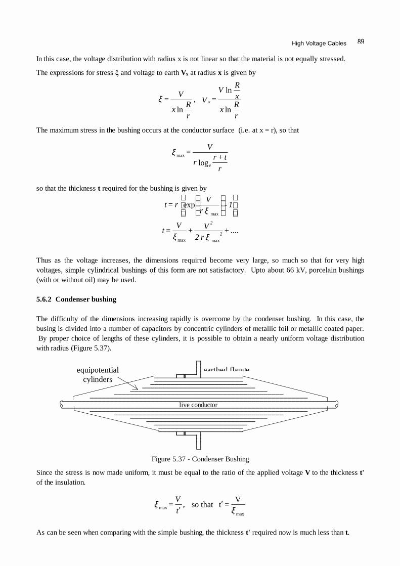
In this case, the voltage distribution with radius x is not linear so that the material is not equally stressed.
The expressions for stress and voltage to earth Vx at radius x is given by
The maximum stress in the bushing occurs at the conductor surface (i.e. at x = r), so that
so that the thickness t required for the bushing is given by
Thus as the voltage increases, the dimensions required become very large, so much so that for very high voltages, simple cylindrical bushings of this form are not satisfactory. Upto about 66 kV, porcelain bushings (with or without oil) may be used. 5.6.2 Condenser bushing The difficulty of the dimensions increasing rapidly is overcome by the condenser bushing. In this case, the busing is divided into a number of capacitors by concentric cylinders of metallic foil or metallic coated paper. By proper choice of lengths of these cylinders, it is possible to obtain a nearly uniform voltage distribution with radius (Figure 5.37).
Since the stress is now made uniform, it must be equal to the ratio of the applied voltage V to the thickness t' of the insulation.
As can be seen when comparing with the simple bushing, the thickness t' required now is much less than t.
r
R x
xR
V = V ,
r
R x
V = x
ln
ln
lnξ
r
t + r r
V =
elogmaxξ
.... + r 2V +
V = t
1 - rV
r = t
2
2
ξξ
ξ
maxmax
max
exp
Figure 5.37 - Condenser Bushing
ξ
ξmax
max
V = t thatso ′
′ ,
t
V =
earthed flangeequipotential cylinders
live conductor

High Voltage Engineering - J R Lucas, 2001
Example A condenser bushing for an r.m.s. voltage of 30 kV to earth is designed to have a uniform radial voltage gradient (Figure 5.38). The insulating material used has a maximum permissible working voltage stress of 10 kV/cm (peak). Assuming a uniform and very small thickness of insulation between each successive foil, determine the radial thickness t' of the bushing. If the length of the bushing at the outermost radius is 10 cm, determine the length at the surface of the conductor (radius 2 cm). Estimate also the thickness t for the bushing without foils, if it is to have the same maximum radial stress.
Since stress is uniform,
The profile of the bushing has the equation y = a/x, at x = t' + 2, y = 10 cm, so that a = 10(t' + 2) = 10(4.24 + 2) therefore, x.y = a = 62.4 at x = r = 2, y = l therefore, l = 62.4/x = 62.4/2 = 31.2 cm In the absence of foils,
Thus in the absence of grading, it is seen that a much greater thickness of insulation is required (14.68 cm as compared to 4.24 cm). In addition to the simple cylinder bushing, and the condenser type bushing, there are other types of bushings, which may consist of more than one material.
10 cm l
Figure 5.38 - Length of Condenser Bushing
cmmax
4.24 = 10
230 =
V = tξ
′
cm 14.68 = 7.342 x 2 = t 8.342 = t +1 .e.i
log
loglog
21
max
∴∴
∴
2.121 = 2 1.5 = t) + (1
22 + t
2
2 30 = 10
rt+ r
r
V =
21
e
ee
ξ