Embed Size (px)
Citation preview
TECHNICAL ARTICLE—PEER-REVIEWED
High-Temperature Stress Relaxation Cracking and StressRupture Observed in a Coke Gasifier Failure
Daniel J. Benac • Douglas B. Olson •
Michael Urzendowski
Submitted: 13 September 2010 / Published online: 7 December 2010
� ASM International 2010
Abstract This article discusses the high-temperature
metal degradation mechanisms that occurred in the failure
of a nine-story tall coke gasifier, located in a refinery power
plant. Cracking of gasifier internals, bulging and stress
rupture of the vessel shell, and escape of hot syngas
resulted in an external fire. The failure mechanisms include
stress relaxation cracking of a large diameter Incoloy Alloy
825 tube, stress rupture of the 4.65-in. thick, 1� chromium
steel shell wall, and oxidation of 1� chromium steel
exposed to hot syngas. The gasifier process and operating
conditions that contributed to the high-temperature degra-
dation will be discussed.
Keywords Coke gasifier � Stress rupture �Reheat cracking � Stress relaxation cracking � Incoloy 825
Introduction
This article discusses the failure of a pressure vessel wall
and internal components that resulted in an external fire at a
nine-story tall coke gasifier, located in a refinery power
plant. After the fire, investigators found that the 4.65-in.
thick shell of the gasifier had bulged and ruptured. This
rupture allowed hot syngas to escape, causing the fire. After
the incident, a section of the vessel wall spanning the area
where the shell failure occurred was cut out to allow internal
inspection. A large irregular hole was found in the dip tube,
an annular tube inside the vessel conducting the hot gas flow
to a water quench. An investigation was performed to
identify possible scenarios for the cause of the incident.
Gasifier Design and Operation
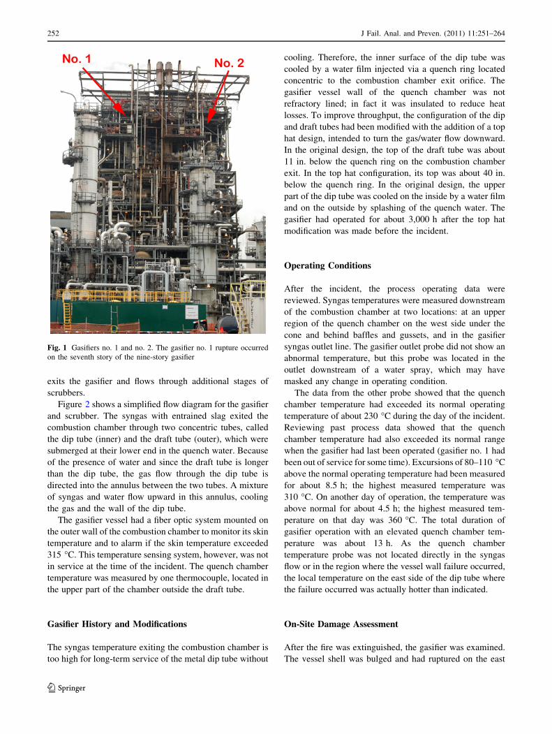
The refinery power plant had two gasifiers, shown in
Fig. 1, each with two stages; an upper, refractory-lined
combustion chamber and a lower water quench chamber.
The gasifier feed is a high concentration water slurry of
petroleum coke containing minor additives. This slurry is
injected into the top of the gasifier where it reacts with
oxygen at high pressure and temperature, producing syn-
thesis gas (syngas), a mixture of hydrogen, carbon
monoxide, carbon dioxide, water vapor, and minor com-
ponents. At the time of the incident, the coke feed rate was
900 tons/day.
During startup of a gasifier, the combustion chamber is
preheated to a temperature [1,040 �C using a fuel–air
burner operating slightly above atmospheric pressure.
During normal operation, the gasifier pressure is much
higher, ranging from 700 to 1,000 psig. On the day of the
incident, the gasifier operating pressure was about
730 psig. Reaction temperatures are moderated by the
water in the slurry to a typical range of 1,300–1,500 �C. At
these temperatures, the noncombustible residue from the
slurry is a molten slag, which flows along with the syngas
out the bottom of the gasifier combustion chamber into a
quench chamber. The syngas and slag are rapidly cooled in
a water bath contained in the quench chamber which also
serves to separate the syngas from the slag. The syngas
This article is an invited paper selected from presentations at MS&T
2010, held October 18–20, 2010, in Houston, Texas, and has been
expanded from the original presentation.
D. J. Benac (&) � D. B. Olson
Baker Engineering and Risk Consultants, San Antonio, TX, USA
e-mail: [email protected]
M. Urzendowski
Valero Energy, San Antonio, TX, USA
123
J Fail. Anal. and Preven. (2011) 11:251–264
DOI 10.1007/s11668-010-9412-1
exits the gasifier and flows through additional stages of
scrubbers.
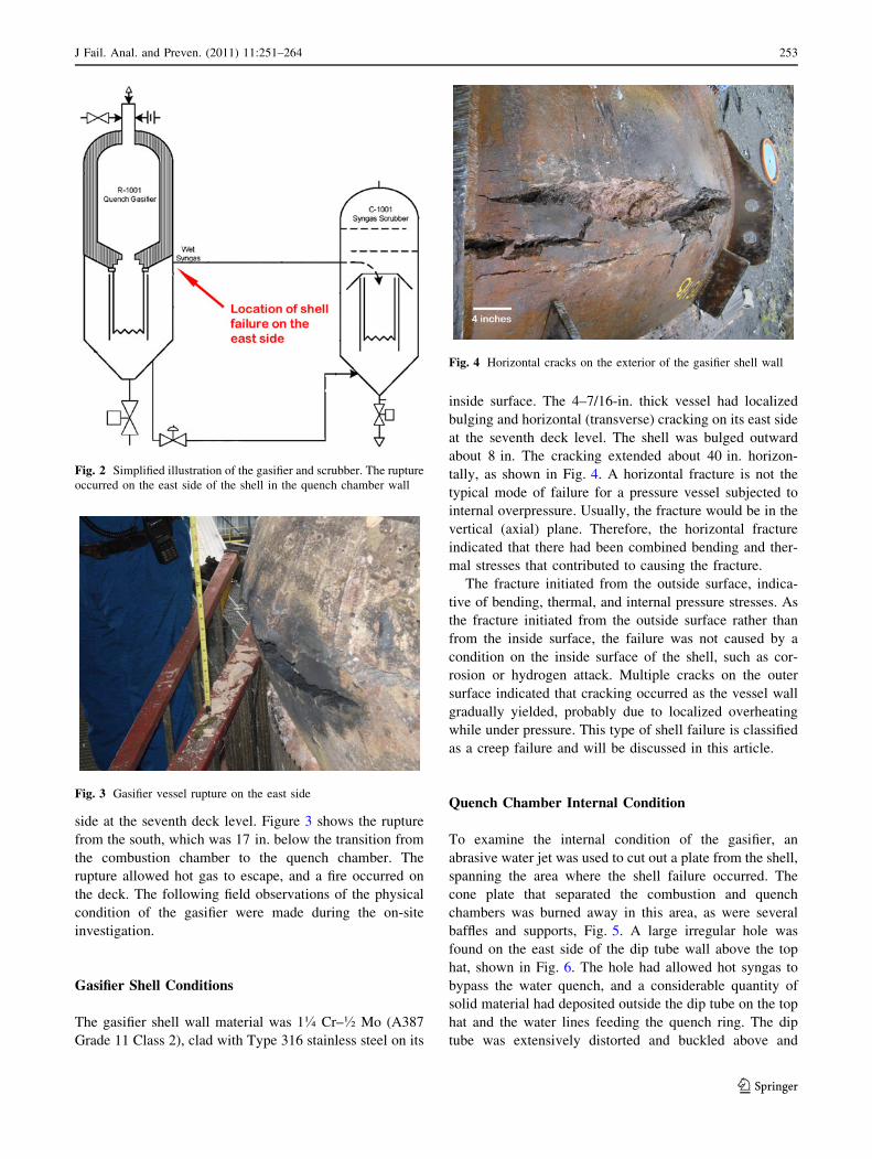
Figure 2 shows a simplified flow diagram for the gasifier
and scrubber. The syngas with entrained slag exited the
combustion chamber through two concentric tubes, called
the dip tube (inner) and the draft tube (outer), which were
submerged at their lower end in the quench water. Because
of the presence of water and since the draft tube is longer
than the dip tube, the gas flow through the dip tube is
directed into the annulus between the two tubes. A mixture
of syngas and water flow upward in this annulus, cooling
the gas and the wall of the dip tube.
The gasifier vessel had a fiber optic system mounted on
the outer wall of the combustion chamber to monitor its skin
temperature and to alarm if the skin temperature exceeded
315 �C. This temperature sensing system, however, was not
in service at the time of the incident. The quench chamber
temperature was measured by one thermocouple, located in
the upper part of the chamber outside the draft tube.
Gasifier History and Modifications
The syngas temperature exiting the combustion chamber is
too high for long-term service of the metal dip tube without
cooling. Therefore, the inner surface of the dip tube was
cooled by a water film injected via a quench ring located
concentric to the combustion chamber exit orifice. The
gasifier vessel wall of the quench chamber was not
refractory lined; in fact it was insulated to reduce heat
losses. To improve throughput, the configuration of the dip
and draft tubes had been modified with the addition of a top
hat design, intended to turn the gas/water flow downward.
In the original design, the top of the draft tube was about
11 in. below the quench ring on the combustion chamber
exit. In the top hat configuration, its top was about 40 in.
below the quench ring. In the original design, the upper
part of the dip tube was cooled on the inside by a water film
and on the outside by splashing of the quench water. The
gasifier had operated for about 3,000 h after the top hat
modification was made before the incident.
Operating Conditions
After the incident, the process operating data were
reviewed. Syngas temperatures were measured downstream
of the combustion chamber at two locations: at an upper
region of the quench chamber on the west side under the
cone and behind baffles and gussets, and in the gasifier
syngas outlet line. The gasifier outlet probe did not show an
abnormal temperature, but this probe was located in the
outlet downstream of a water spray, which may have
masked any change in operating condition.
The data from the other probe showed that the quench
chamber temperature had exceeded its normal operating
temperature of about 230 �C during the day of the incident.
Reviewing past process data showed that the quench
chamber temperature had also exceeded its normal range
when the gasifier had last been operated (gasifier no. 1 had
been out of service for some time). Excursions of 80–110 �C
above the normal operating temperature had been measured
for about 8.5 h; the highest measured temperature was
310 �C. On another day of operation, the temperature was
above normal for about 4.5 h; the highest measured tem-
perature on that day was 360 �C. The total duration of
gasifier operation with an elevated quench chamber tem-
perature was about 13 h. As the quench chamber
temperature probe was not located directly in the syngas
flow or in the region where the vessel wall failure occurred,
the local temperature on the east side of the dip tube where
the failure occurred was actually hotter than indicated.
On-Site Damage Assessment
After the fire was extinguished, the gasifier was examined.
The vessel shell was bulged and had ruptured on the east
Fig. 1 Gasifiers no. 1 and no. 2. The gasifier no. 1 rupture occurred
on the seventh story of the nine-story gasifier
252 J Fail. Anal. and Preven. (2011) 11:251–264
123
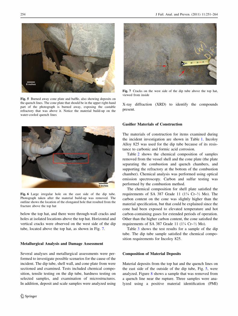
side at the seventh deck level. Figure 3 shows the rupture
from the south, which was 17 in. below the transition from
the combustion chamber to the quench chamber. The
rupture allowed hot gas to escape, and a fire occurred on
the deck. The following field observations of the physical
condition of the gasifier were made during the on-site
investigation.
Gasifier Shell Conditions
The gasifier shell wall material was 1� Cr–� Mo (A387
Grade 11 Class 2), clad with Type 316 stainless steel on its
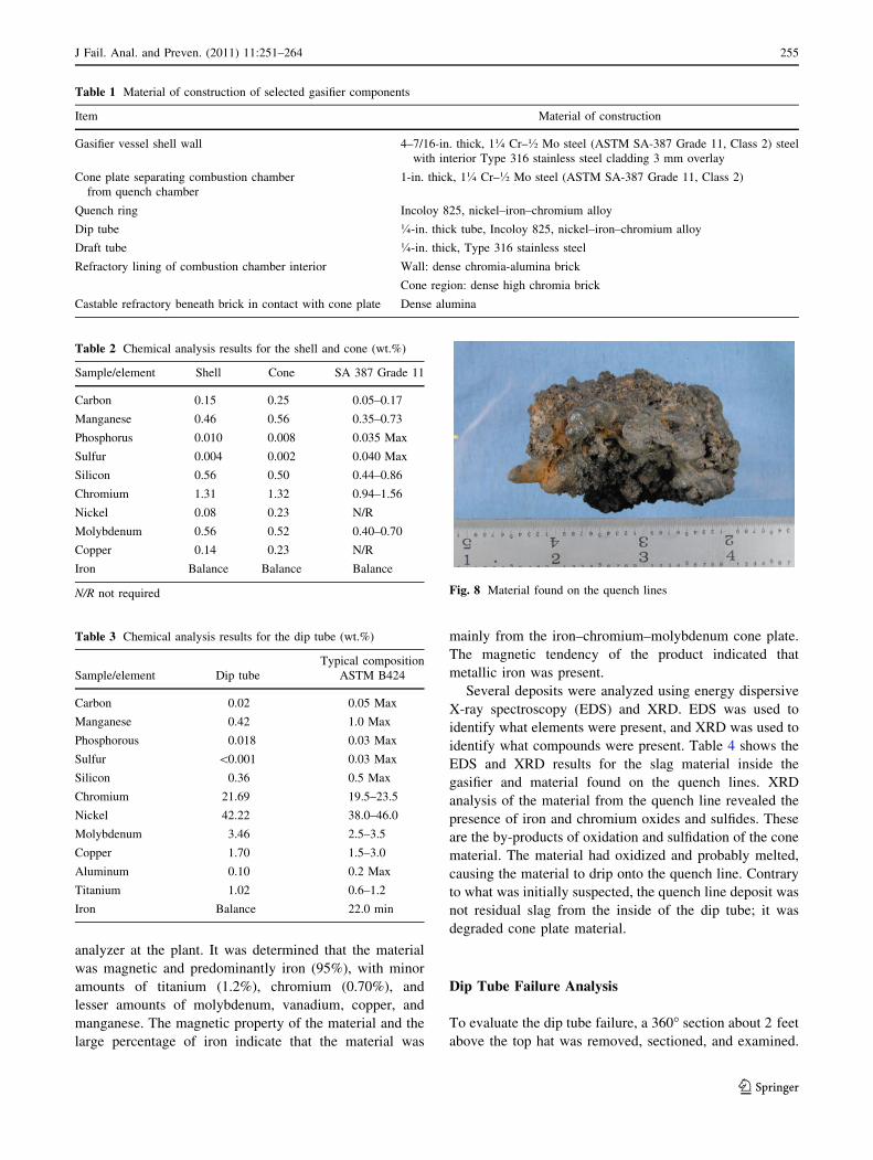
inside surface. The 4–7/16-in. thick vessel had localized
bulging and horizontal (transverse) cracking on its east side
at the seventh deck level. The shell was bulged outward
about 8 in. The cracking extended about 40 in. horizon-
tally, as shown in Fig. 4. A horizontal fracture is not the
typical mode of failure for a pressure vessel subjected to
internal overpressure. Usually, the fracture would be in the
vertical (axial) plane. Therefore, the horizontal fracture
indicated that there had been combined bending and ther-
mal stresses that contributed to causing the fracture.
The fracture initiated from the outside surface, indica-
tive of bending, thermal, and internal pressure stresses. As
the fracture initiated from the outside surface rather than
from the inside surface, the failure was not caused by a
condition on the inside surface of the shell, such as cor-
rosion or hydrogen attack. Multiple cracks on the outer
surface indicated that cracking occurred as the vessel wall
gradually yielded, probably due to localized overheating
while under pressure. This type of shell failure is classified
as a creep failure and will be discussed in this article.
Quench Chamber Internal Condition
To examine the internal condition of the gasifier, an
abrasive water jet was used to cut out a plate from the shell,
spanning the area where the shell failure occurred. The
cone plate that separated the combustion and quench
chambers was burned away in this area, as were several
baffles and supports, Fig. 5. A large irregular hole was
found on the east side of the dip tube wall above the top
hat, shown in Fig. 6. The hole had allowed hot syngas to
bypass the water quench, and a considerable quantity of
solid material had deposited outside the dip tube on the top
hat and the water lines feeding the quench ring. The dip
tube was extensively distorted and buckled above and
Fig. 2 Simplified illustration of the gasifier and scrubber. The rupture
occurred on the east side of the shell in the quench chamber wall
Fig. 3 Gasifier vessel rupture on the east side
Fig. 4 Horizontal cracks on the exterior of the gasifier shell wall
J Fail. Anal. and Preven. (2011) 11:251–264 253
123
below the top hat, and there were through-wall cracks and
holes at isolated locations above the top hat. Horizontal and
vertical cracks were observed on the west side of the dip
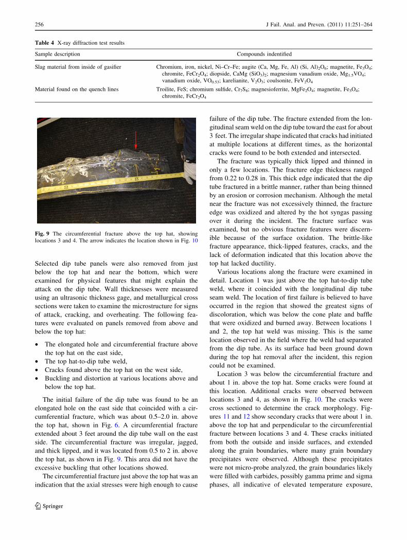
tube, located above the top hat, as shown in Fig. 7.
Metallurgical Analysis and Damage Assessment
Several analyses and metallurgical assessments were per-
formed to investigate possible scenarios for the cause of the
incident. The dip tube, shell wall, and cone plate from were
sectioned and examined. Tests included chemical compo-
sition, tensile testing on the dip tube, hardness testing on
selected samples, and examination of microstructures.
In addition, deposit and scale samples were analyzed using
X-ray diffraction (XRD) to identify the compounds
present.
Gasifier Materials of Construction
The materials of construction for items examined during
the incident investigation are shown in Table 1. Incoloy
Alloy 825 was used for the dip tube because of its resis-
tance to carbonic and formic acid corrosion.
Table 2 shows the chemical composition of samples
removed from the vessel shell and the cone plate (the plate
separating the combustion and quench chambers, and
supporting the refractory at the bottom of the combustion
chamber). Chemical analysis was performed using optical
emission spectroscopy. Carbon and sulfur testing was
performed by the combustion method.
The chemical composition for shell plate satisfied the
requirements of SA 387 Grade 11 (1� Cr–� Mo). The
carbon content on the cone was slightly higher than the
material specification, but that could be explained since the
cone had been exposed to elevated temperature and hot
carbon-containing gases for extended periods of operation.
Other than the higher carbon content, the cone satisfied the
requirements of SA 387 Grade 11 (1� Cr–� Mo).
Table 3 shows the test results for a sample of the dip
tube. The dip tube sample satisfied the chemical compo-
sition requirements for Incoloy 825.
Composition of Material Deposits
Material deposits from the top hat and the quench lines on
the east side of the outside of the dip tube, Fig. 5, were
analyzed. Figure 8 shows a sample that was removed from
a quench line near the rupture. Three samples were ana-
lyzed using a positive material identification (PMI)
Fig. 5 Burned away cone plate and baffle, also showing deposits on
the quench lines. The cone plate that should be in the upper right-hand
part of the photograph is burned away, exposing the castable
refractory that was above it. Notice the material build-up on the
water-cooled quench lines
Fig. 6 Large irregular hole on the east side of the dip tube.
Photograph taken after the material build-up was removed. The
outline shows the location of the elongated hole that resulted from the
fracture above the top hat
Fig. 7 Cracks on the west side of the dip tube above the top hat,
viewed from inside
254 J Fail. Anal. and Preven. (2011) 11:251–264
123
analyzer at the plant. It was determined that the material
was magnetic and predominantly iron (95%), with minor
amounts of titanium (1.2%), chromium (0.70%), and
lesser amounts of molybdenum, vanadium, copper, and
manganese. The magnetic property of the material and the
large percentage of iron indicate that the material was
mainly from the iron–chromium–molybdenum cone plate.
The magnetic tendency of the product indicated that
metallic iron was present.
Several deposits were analyzed using energy dispersive
X-ray spectroscopy (EDS) and XRD. EDS was used to
identify what elements were present, and XRD was used to
identify what compounds were present. Table 4 shows the
EDS and XRD results for the slag material inside the
gasifier and material found on the quench lines. XRD
analysis of the material from the quench line revealed the
presence of iron and chromium oxides and sulfides. These
are the by-products of oxidation and sulfidation of the cone
material. The material had oxidized and probably melted,
causing the material to drip onto the quench line. Contrary
to what was initially suspected, the quench line deposit was
not residual slag from the inside of the dip tube; it was
degraded cone plate material.
Dip Tube Failure Analysis
To evaluate the dip tube failure, a 360� section about 2 feet
above the top hat was removed, sectioned, and examined.
Table 1 Material of construction of selected gasifier components
Item Material of construction
Gasifier vessel shell wall 4–7/16-in. thick, 1� Cr–� Mo steel (ASTM SA-387 Grade 11, Class 2) steel
with interior Type 316 stainless steel cladding 3 mm overlay
Cone plate separating combustion chamber
from quench chamber
1-in. thick, 1� Cr–� Mo steel (ASTM SA-387 Grade 11, Class 2)
Quench ring Incoloy 825, nickel–iron–chromium alloy
Dip tube �-in. thick tube, Incoloy 825, nickel–iron–chromium alloy
Draft tube �-in. thick, Type 316 stainless steel
Refractory lining of combustion chamber interior Wall: dense chromia-alumina brick
Cone region: dense high chromia brick
Castable refractory beneath brick in contact with cone plate Dense alumina
Table 2 Chemical analysis results for the shell and cone (wt.%)
Sample/element Shell Cone SA 387 Grade 11
Carbon 0.15 0.25 0.05–0.17
Manganese 0.46 0.56 0.35–0.73
Phosphorus 0.010 0.008 0.035 Max
Sulfur 0.004 0.002 0.040 Max
Silicon 0.56 0.50 0.44–0.86
Chromium 1.31 1.32 0.94–1.56
Nickel 0.08 0.23 N/R
Molybdenum 0.56 0.52 0.40–0.70
Copper 0.14 0.23 N/R
Iron Balance Balance Balance
N/R not required
Table 3 Chemical analysis results for the dip tube (wt.%)
Sample/element Dip tube
Typical composition
ASTM B424
Carbon 0.02 0.05 Max
Manganese 0.42 1.0 Max
Phosphorous 0.018 0.03 Max
Sulfur \0.001 0.03 Max
Silicon 0.36 0.5 Max
Chromium 21.69 19.5–23.5
Nickel 42.22 38.0–46.0
Molybdenum 3.46 2.5–3.5
Copper 1.70 1.5–3.0
Aluminum 0.10 0.2 Max
Titanium 1.02 0.6–1.2
Iron Balance 22.0 min
Fig. 8 Material found on the quench lines
J Fail. Anal. and Preven. (2011) 11:251–264 255
123
Selected dip tube panels were also removed from just
below the top hat and near the bottom, which were
examined for physical features that might explain the
attack on the dip tube. Wall thicknesses were measured
using an ultrasonic thickness gage, and metallurgical cross
sections were taken to examine the microstructure for signs
of attack, cracking, and overheating. The following fea-
tures were evaluated on panels removed from above and
below the top hat:
• The elongated hole and circumferential fracture above
the top hat on the east side,
• The top hat-to-dip tube weld,
• Cracks found above the top hat on the west side,
• Buckling and distortion at various locations above and
below the top hat.
The initial failure of the dip tube was found to be an
elongated hole on the east side that coincided with a cir-
cumferential fracture, which was about 0.5–2.0 in. above
the top hat, shown in Fig. 6. A circumferential fracture
extended about 3 feet around the dip tube wall on the east
side. The circumferential fracture was irregular, jagged,
and thick lipped, and it was located from 0.5 to 2 in. above
the top hat, as shown in Fig. 9. This area did not have the
excessive buckling that other locations showed.
The circumferential fracture just above the top hat was an
indication that the axial stresses were high enough to cause
failure of the dip tube. The fracture extended from the lon-
gitudinal seam weld on the dip tube toward the east for about
3 feet. The irregular shape indicated that cracks had initiated
at multiple locations at different times, as the horizontal
cracks were found to be both extended and intersected.
The fracture was typically thick lipped and thinned in
only a few locations. The fracture edge thickness ranged
from 0.22 to 0.28 in. This thick edge indicated that the dip
tube fractured in a brittle manner, rather than being thinned
by an erosion or corrosion mechanism. Although the metal
near the fracture was not excessively thinned, the fracture
edge was oxidized and altered by the hot syngas passing
over it during the incident. The fracture surface was
examined, but no obvious fracture features were discern-
ible because of the surface oxidation. The brittle-like
fracture appearance, thick-lipped features, cracks, and the
lack of deformation indicated that this location above the
top hat lacked ductility.
Various locations along the fracture were examined in
detail. Location 1 was just above the top hat-to-dip tube
weld, where it coincided with the longitudinal dip tube
seam weld. The location of first failure is believed to have
occurred in the region that showed the greatest signs of
discoloration, which was below the cone plate and baffle
that were oxidized and burned away. Between locations 1
and 2, the top hat weld was missing. This is the same
location observed in the field where the weld had separated
from the dip tube. As its surface had been ground down
during the top hat removal after the incident, this region
could not be examined.
Location 3 was below the circumferential fracture and
about 1 in. above the top hat. Some cracks were found at
this location. Additional cracks were observed between
locations 3 and 4, as shown in Fig. 10. The cracks were
cross sectioned to determine the crack morphology. Fig-
ures 11 and 12 show secondary cracks that were about 1 in.
above the top hat and perpendicular to the circumferential
fracture between locations 3 and 4. These cracks initiated
from both the outside and inside surfaces, and extended
along the grain boundaries, where many grain boundary
precipitates were observed. Although these precipitates
were not micro-probe analyzed, the grain boundaries likely
were filled with carbides, possibly gamma prime and sigma
phases, all indicative of elevated temperature exposure,
Table 4 X-ray diffraction test results
Sample description Compounds indentified
Slag material from inside of gasifier Chromium, iron, nickel, Ni–Cr–Fe; augite (Ca, Mg, Fe, Al) (Si, Al)2O6; magnetite, Fe3O4;
chromite, FeCr2O4; diopside, CaMg (SiO3)2; magnesium vanadium oxide, Mg1.5VO4;
vanadium oxide, VO0.53; karelianite, V2O3; coulsonite, FeV2O4
Material found on the quench lines Troilite, FeS; chromium sulfide, Cr7S8; magnesioferrite, MgFe2O4; magnetite, Fe3O4;
chromite, FeCr2O4
Fig. 9 The circumferential fracture above the top hat, showing
locations 3 and 4. The arrow indicates the location shown in Fig. 10
256 J Fail. Anal. and Preven. (2011) 11:251–264
123
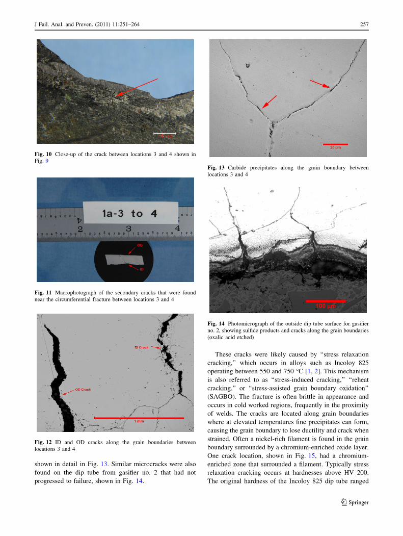
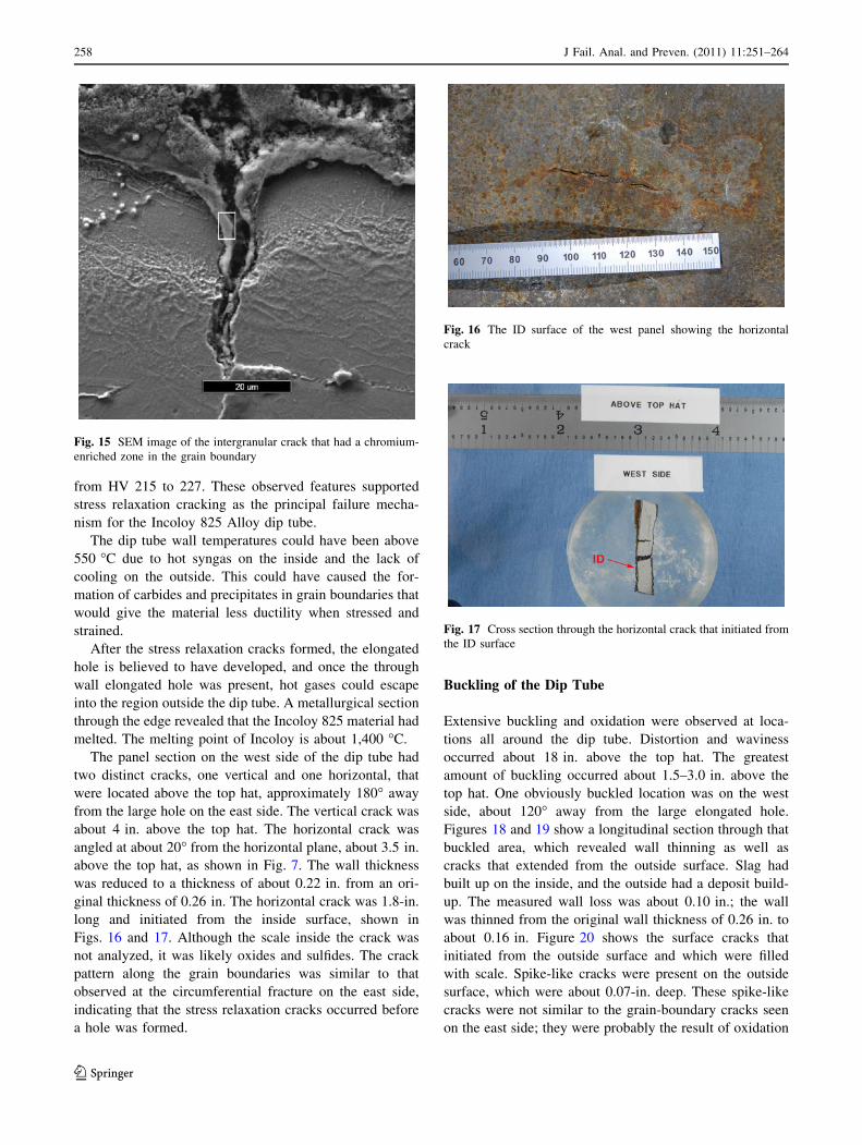
shown in detail in Fig. 13. Similar microcracks were also
found on the dip tube from gasifier no. 2 that had not
progressed to failure, shown in Fig. 14.
These cracks were likely caused by ‘‘stress relaxation
cracking,’’ which occurs in alloys such as Incoloy 825
operating between 550 and 750 �C [1, 2]. This mechanism
is also referred to as ‘‘stress-induced cracking,’’ ‘‘reheat
cracking,’’ or ‘‘stress-assisted grain boundary oxidation’’
(SAGBO). The fracture is often brittle in appearance and
occurs in cold worked regions, frequently in the proximity
of welds. The cracks are located along grain boundaries
where at elevated temperatures fine precipitates can form,
causing the grain boundary to lose ductility and crack when
strained. Often a nickel-rich filament is found in the grain
boundary surrounded by a chromium-enriched oxide layer.
One crack location, shown in Fig. 15, had a chromium-
enriched zone that surrounded a filament. Typically stress
relaxation cracking occurs at hardnesses above HV 200.
The original hardness of the Incoloy 825 dip tube ranged
Fig. 10 Close-up of the crack between locations 3 and 4 shown in
Fig. 9
Fig. 11 Macrophotograph of the secondary cracks that were found
near the circumferential fracture between locations 3 and 4
Fig. 12 ID and OD cracks along the grain boundaries between
locations 3 and 4
Fig. 13 Carbide precipitates along the grain boundary between
locations 3 and 4
Fig. 14 Photomicrograph of the outside dip tube surface for gasifier
no. 2, showing sulfide products and cracks along the grain boundaries
(oxalic acid etched)
J Fail. Anal. and Preven. (2011) 11:251–264 257
123
from HV 215 to 227. These observed features supported
stress relaxation cracking as the principal failure mecha-
nism for the Incoloy 825 Alloy dip tube.
The dip tube wall temperatures could have been above
550 �C due to hot syngas on the inside and the lack of
cooling on the outside. This could have caused the for-
mation of carbides and precipitates in grain boundaries that
would give the material less ductility when stressed and
strained.
After the stress relaxation cracks formed, the elongated
hole is believed to have developed, and once the through
wall elongated hole was present, hot gases could escape
into the region outside the dip tube. A metallurgical section
through the edge revealed that the Incoloy 825 material had
melted. The melting point of Incoloy is about 1,400 �C.
The panel section on the west side of the dip tube had
two distinct cracks, one vertical and one horizontal, that
were located above the top hat, approximately 180� away
from the large hole on the east side. The vertical crack was
about 4 in. above the top hat. The horizontal crack was
angled at about 20� from the horizontal plane, about 3.5 in.
above the top hat, as shown in Fig. 7. The wall thickness
was reduced to a thickness of about 0.22 in. from an ori-
ginal thickness of 0.26 in. The horizontal crack was 1.8-in.
long and initiated from the inside surface, shown in
Figs. 16 and 17. Although the scale inside the crack was
not analyzed, it was likely oxides and sulfides. The crack
pattern along the grain boundaries was similar to that
observed at the circumferential fracture on the east side,
indicating that the stress relaxation cracks occurred before
a hole was formed.
Buckling of the Dip Tube
Extensive buckling and oxidation were observed at loca-
tions all around the dip tube. Distortion and waviness
occurred about 18 in. above the top hat. The greatest
amount of buckling occurred about 1.5–3.0 in. above the
top hat. One obviously buckled location was on the west
side, about 120� away from the large elongated hole.
Figures 18 and 19 show a longitudinal section through that
buckled area, which revealed wall thinning as well as
cracks that extended from the outside surface. Slag had
built up on the inside, and the outside had a deposit build-
up. The measured wall loss was about 0.10 in.; the wall
was thinned from the original wall thickness of 0.26 in. to
about 0.16 in. Figure 20 shows the surface cracks that
initiated from the outside surface and which were filled
with scale. Spike-like cracks were present on the outside
surface, which were about 0.07-in. deep. These spike-like
cracks were not similar to the grain-boundary cracks seen
on the east side; they were probably the result of oxidation
Fig. 15 SEM image of the intergranular crack that had a chromium-
enriched zone in the grain boundary
Fig. 16 The ID surface of the west panel showing the horizontal
crack
Fig. 17 Cross section through the horizontal crack that initiated from
the ID surface
258 J Fail. Anal. and Preven. (2011) 11:251–264
123

and the elevated temperature that developed after the hole
formed in the dip tube. EDS analysis showed that the
deposits in the crack contained mostly sulfur. The cracks
were on the compression side of the buckle, which is
unusual since cracks typically initiate from the tension
side.
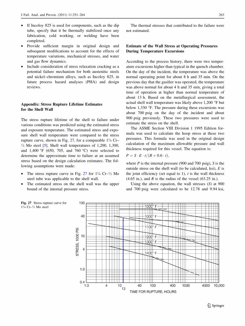
At elevated temperatures, especially above 540 �C, the
ultimate strength and elastic modulus of Incoloy 825
decreases, as shown in Fig. 21 [3]. Buckling occurred in
the dip tube due to compression stress exceeding the yield
strength of the material, caused by the increase in tem-
perature. Additional mechanical stresses were created by
the rigid supports to the top hat. Therefore, the damage to
the dip tube indicated that it was exposed to temperatures
[540 �C, but the actual wall temperature could not be
determined. Most of the buckling likely occurred during
the incident when hot syngas escaped from the dip tube
hole on the east side.
Mechanical Testing
Four samples were taken from the dip tube to determine if
the room temperature tensile properties had been affected.
Tensile test specimens were prepared and tested in accor-
dance with ASTM A370 (Mechanical Testing of Steel
Products). Table 5 shows the tensile test results, which did
not reveal significant changes in the room temperature
properties. The yield strength of the samples from above
the top hat was slightly lower compared to samples from
below the top hat, but the yield strength was still close to
the typical room temperature properties for Incoloy 825.
Although the dip tube was exposed to elevated tempera-
tures above the top hat, the wall material did not show a
loss of ductility at room temperature.
Incoloy 825 can be supplied in either the solution
annealed or the stabilized condition, where it would have
the best resistance to ‘‘stress relaxation cracking.’’ Such
stabilization treatment requires that the material be heat
treated in the temperature range of 940–955 �C. It was not
verified whether the dip tube material was supplied in a
stabilized condition in order to have had a greater resis-
tance to the formation of carbides and precipitates.
Cone Plate Failure Analysis
As a result of the hole in the dip tube, hot syngas impinged
on the baffle and the bottom side of the cone plate. The 1-
in. thick cone plate, which separated the combustion
chamber from the quench chamber and supported the
refractory, was deteriorated and completely missing from
the area above the hole in the dip tube. Figure 22 shows
Fig. 18 Longitudinal section through the buckling on the northwest
side of the dip tube. The top hat was located at the far right
Fig. 19 Longitudinal section showing cracks on the outside of the
dip tube. The arrow indicates the outside surface
Fig. 20 Photomicrograph of the cracks and oxidation on the outside
surface of the dip tube
J Fail. Anal. and Preven. (2011) 11:251–264 259
123
part of the remaining cone material removed for charac-
terization. Metallurgical sections through this cone plate
material indicated that the damage was predominately due
to high-temperature oxidation and erosion. In addition,
there were isolated regions that showed evidence of
incipient melting, Fig. 23. These regions were also hard-
ened to Rockwell HRC 50, probably from being heated to
elevated temperature and then rapidly cooled.
For this particular steel (1� Cr–� Mo), incipient
melting occurs at about 1,420 �C, meaning that the syngas
must have been significantly hotter. The melting observed
on the Incoloy 825 dip tube also indicated that the hot gas
was significantly hotter than 1,425 �C. These findings are
consistent with the identification of the deposits found on
the top hat resulting from melting and oxidation of the cone
plate.
Fig. 21 Stress versus
temperature curves for Incoloy
825. Notice the decrease in
ultimate strength and elongation
at temperatures [540 �C.
Above 590 �C, the elongation
increases rapidly with
temperature
Table 5 Tensile test results for the Incoloy 825 dip tube
Specimen ID
Ultimate tensile
strength (ksi)
Yield
strength (ksi) Elongation (%)
T1: Dip tube below the water line about 2 feet above the bottom 98.5 53.0 60
T2: Dip tube below top hat in a distorted region 102.0 61.5 52
T3: Dip tube above top hat on the west side in distorted region 93.5 50.5 56
T4: Dip tube above the top hat on the east side in distorted region 95.5 47.3 62
Typical Incoloy 825 96.0 49.0 45
260 J Fail. Anal. and Preven. (2011) 11:251–264
123

Shell Wall Failure Analysis
As a result of the hole in the east side of the dip tube, hot
syngas impinged not only on the baffle and cone plate, but
also on the gasifier shell wall. The 4.65-in. thick vessel
shell wall failed due to elevated temperature stress rupture
(creep failure), which was indicated by the extensive
bulging, microcracking, and void formation on its outside
surface. Figure 24 shows the stress rupture voids near the
outside surface. Microstructural assessment of the shell
wall indicated the degeneration of the typical microstruc-
ture phase pearlite and in some locations the formation of
spheroidized cementite. Figure 25 shows the pearlite and
ferrite structure from a location that did not get as hot, but
still had the same lamellar colonies; Fig. 26 shows com-
plete spheroidization. This change in microstructures in 1�chromium steel typically occurs only at elevated temper-
atures, but below the critical transformation temperature,
which is near 720 �C. Complete phase transformation can
occur above this temperature. There were no signs of phase
transformation except where the hot gases escaped, thus it
is unlikely that the shell was heated above 760 �C before
the failure occurred.
In order for the shell to exhibit a creep failure, the wall
had to be heated to temperatures greater than its normal
operating temperature. Typically, the maximum operating
temperature for 1� Cr–� Mo steel is about 550 �C [4]. At
temperatures greater than this, failure will occur rapidly.
Visual examination showed that hot syngas escaped through
the hole in the dip tube and impinged on the cone plate and
baffles, causing them to oxidize and melt. This hot gas flow
also heated the shell wall to near 700 �C, where it began to
soften, bulge, and fail due to stress rupture.
Fig. 22 Oxidized and burned cone material
Fig. 23 Photomicrograph of cross-sectioned cone plate material
showing incipient melting (unetched)
Fig. 24 Photomicrograph of the outside surface of the shell wall near
the rupture location, showing the stress rupture voids (unetched)
Fig. 25 Photomicrograph of the outside surface of the shell wall,
about 11 in. above the rupture, showing pearlite colonies (nital
etched)
J Fail. Anal. and Preven. (2011) 11:251–264 261
123

Thermal stresses played a major role in causing the shell
failure, rather than just stress from internal pressure. This
explains why the main failure cracks were horizontal
(transverse) rather than axial. The affect of thermal stresses
was also indicated by the presence of scale-filled cracks
found in the stainless steel liner on the vessel wall.
The following question was asked: What was the
approximate temperature and time of exposure that caused
the shell to rupture? To address this question, the time for
the shell wall to fail at elevated temperatures was estimated
by calculating the approximate shell stress at its internal
pressure and comparing this stress and exposure tempera-
ture to the stress rupture curve for a comparable 1� Cr–�Mo steel. This calculation is presented in the ‘‘Appendix.’’
The metallurgical assessment of the shell microstructure
indicated that the shell wall temperature was less than
about 720 �C. This implies that the shell was gradually
heated over time. An exposure time was estimated from the
process thermocouple data, which showed higher than
typical operating temperature for a total of about 13 h.
Based on the metallurgical assessment, the stress rupture
curve, and the shell stress calculations, the temperature
required for rupture to occur in 13 h was approximately
690 ± 15 �C.
The investigation concluded that impingement of hot
combustion gases (much hotter than 690 �C) escaping
through the dip tube hole onto the shell wall caused the
stress rupture failure of the gasifier no. 1 vessel.
Conclusions
This gasifier incident occurred because a hole formed in the
dip tube wall, allowing hot syngas to directly escape
without passing through the quench, causing overheating of
the vessel shell wall. The dip tube, a critical part of the
syngas quench process, had been modified with the addi-
tion of a top hat that altered the flow dynamics, mechanical
support, and external cooling of the dip tube, leading to
failure of the Incoloy 825 dip tube wall above the top hat
and ultimately, the failure of the gasifier vessel.
The metallurgical assessment found that the dip tube had
a brittle-like circumferential fracture above the top hat,
which resulted in the formation of oxidation, scaling, and
stress-assisted grain boundary cracks. The dip tube cracks
and fractures can best be explained by a phenomenon
known as ‘‘stress relaxation cracking,’’ which occurs in
austenitic stainless steels such as the Incoloy Alloy 825
operating between 550 and 750 �C. At these temperatures,
fine precipitates form, which in turn causes the grain
boundaries to lose ductility, causing the metal to crack
along the grain boundaries when strained. Widespread
degradation of the dip tube wall was observed on all sides
above the top hat, indicating that the phenomenon had not
just occurred at an isolated location.
Hot syngas escaped from the normal flow to the quench
through the hole in the dip tube wall, overheating and
oxidizing the 1-in. thick cone plate that separated the
combustion chamber from the quench chamber. The syngas
also impinged on the 4.65-in. thick, 1� Cr–� Mo steel
shell wall of the pressure vessel. The shell wall overheated,
softened, bulged, and then failed due to stress rupture.
Thermal stresses in the thick wall plate played a larger role
than stress from the operating pressure, as shown by the
failure cracks that were transverse rather than along the
axis of the vessel. Based on the metallurgical assessment,
data and calculations for stress rupture, the average shell
wall temperature necessary for failure was approximately
690 ± 25 �C (1,275 ± 25 �F) at about 13 h, the estimated
duration that the gasifier operated at higher than normal
temperature.
Recommendations
Based on the results of this investigation, the following
items may be considered for future operational and design
concerns regarding gasifiers. These recommendations may
be evaluated based upon cost, feasibility, and redundancy
of designs. These recommendations are not intended as a
comprehensive list, but may provide partial guidance for
safe operation of gasifiers.
• Install and monitor temperature sensors at several select
locations to give better measurement of normal and
abnormal temperatures for the vessel skin and gas
temperatures in the gasifier.
Fig. 26 Photomicrograph near inside surface of the shell wall, about
19 in. below the rupture, showing the spheroidized structure (nital
etched) focus
262 J Fail. Anal. and Preven. (2011) 11:251–264
123
• If Incoloy 825 is used for components, such as the dip
tube, specify that it be thermally stabilized once any
fabrication, cold working, or welding have been
completed.
• Provide sufficient margin in original design and
subsequent modifications to account for the effects of
temperature variations, mechanical stresses, and water
and gas flow dynamics.
• Include consideration of stress relaxation cracking as a
potential failure mechanism for both austenitic steels
and nickel–chromium alloys, such as Incoloy 825, in
future process hazard analyses (PHA) and design
reviews.
Appendix: Stress Rupture Lifetime Estimates
for the Shell Wall
The stress rupture lifetime of the shell to failure under
various conditions was predicted using the estimated stress
and exposure temperature. The estimated stress and expo-
sure shell wall temperature were compared to the stress
rupture curve, shown in Fig. 27, for a comparable 1� Cr–
� Mo steel [5]. Shell wall temperatures of 1,200, 1,300,
and 1,400 �F (650, 705, and 760 �C) were selected to
determine the approximate time to failure at an assumed
stress based on the design calculation estimates. The fol-
lowing assumptions were made:
• The stress rupture curve in Fig. 27 for 1� Cr–� Mo
steel tube was applicable to the shell wall.
• The estimated stress on the shell wall was the upper
bound of the internal pressure stress.
The thermal stresses that contributed to the failure were
not estimated.
Estimate of the Wall Stress at Operating Pressures
During Temperature Excursions
According to the process history, there were two temper-
ature excursions higher than typical in the quench chamber.
On the day of the incident, the temperature was above the
normal operating point for about 8 h and 35 min. On the
previous day that the gasifier was operated, the temperature
was above normal for about 4 h and 35 min, giving a total
time of operation at higher than normal temperature of
about 13 h. Based on the metallurgical assessment, the
actual shell wall temperature was likely above 1,200 �F but
below 1,330 �F. The pressure during these excursions was
about 700 psig on the day of the incident and about
900 psig previously. These two pressures were used to
estimate the stress on the shell.
The ASME Section VIII Division 1 1995 Edition for-
mula was used to calculate the hoop stress at these two
pressures. This formula was used in the original design
calculation of the maximum allowable pressure and wall
thickness required for this vessel. The equation is:
P ¼ S � E � t= Rþ 0:6 � tð Þ;
where P is the internal pressure (900 and 700 psig), S is the
outside stress on the shell wall (to be calculated, ksi), E is
the joint efficiency (set equal to 1), t is the wall thickness
(4.65 in.), and R is the radius of the vessel (63.25 in.).
Using the above equation, the wall stresses (S) at 900
and 700 psig were calculated to be 12.78 and 9.94 ksi,
Fig. 27 Stress rupture curve for
1� Cr–� Mo steel
J Fail. Anal. and Preven. (2011) 11:251–264 263
123
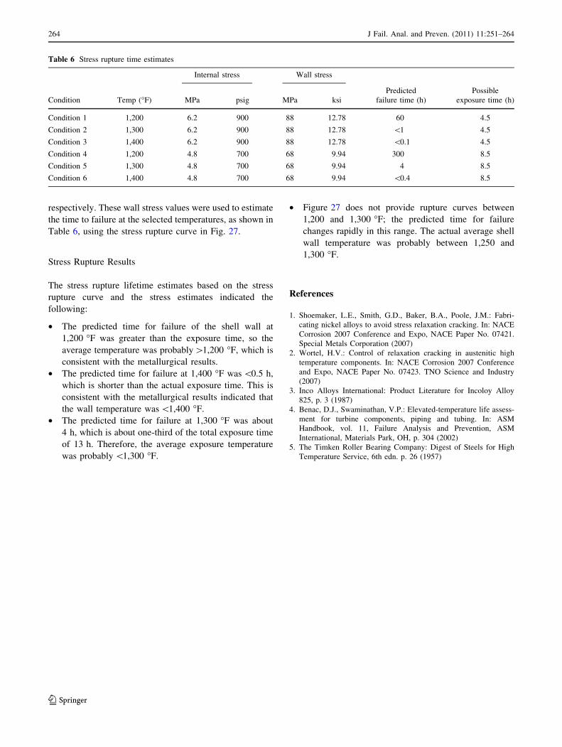
respectively. These wall stress values were used to estimate
the time to failure at the selected temperatures, as shown in
Table 6, using the stress rupture curve in Fig. 27.
Stress Rupture Results
The stress rupture lifetime estimates based on the stress
rupture curve and the stress estimates indicated the
following:
• The predicted time for failure of the shell wall at
1,200 �F was greater than the exposure time, so the
average temperature was probably[1,200 �F, which is
consistent with the metallurgical results.
• The predicted time for failure at 1,400 �F was \0.5 h,
which is shorter than the actual exposure time. This is
consistent with the metallurgical results indicated that
the wall temperature was \1,400 �F.
• The predicted time for failure at 1,300 �F was about
4 h, which is about one-third of the total exposure time
of 13 h. Therefore, the average exposure temperature
was probably \1,300 �F.
• Figure 27 does not provide rupture curves between
1,200 and 1,300 �F; the predicted time for failure
changes rapidly in this range. The actual average shell
wall temperature was probably between 1,250 and
1,300 �F.
References
1. Shoemaker, L.E., Smith, G.D., Baker, B.A., Poole, J.M.: Fabri-
cating nickel alloys to avoid stress relaxation cracking. In: NACE
Corrosion 2007 Conference and Expo, NACE Paper No. 07421.
Special Metals Corporation (2007)
2. Wortel, H.V.: Control of relaxation cracking in austenitic high
temperature components. In: NACE Corrosion 2007 Conference
and Expo, NACE Paper No. 07423. TNO Science and Industry
(2007)
3. Inco Alloys International: Product Literature for Incoloy Alloy
825, p. 3 (1987)
4. Benac, D.J., Swaminathan, V.P.: Elevated-temperature life assess-
ment for turbine components, piping and tubing. In: ASM
Handbook, vol. 11, Failure Analysis and Prevention, ASM
International, Materials Park, OH, p. 304 (2002)
5. The Timken Roller Bearing Company: Digest of Steels for High
Temperature Service, 6th edn. p. 26 (1957)
Table 6 Stress rupture time estimates
Condition Temp (�F)
Internal stress Wall stress
MPa psig MPa ksi
Predicted
failure time (h)
Possible
exposure time (h)
Condition 1 1,200 6.2 900 88 12.78 60 4.5
Condition 2 1,300 6.2 900 88 12.78 \1 4.5
Condition 3 1,400 6.2 900 88 12.78 \0.1 4.5
Condition 4 1,200 4.8 700 68 9.94 300 8.5
Condition 5 1,300 4.8 700 68 9.94 4 8.5
Condition 6 1,400 4.8 700 68 9.94 \0.4 8.5
264 J Fail. Anal. and Preven. (2011) 11:251–264
123