Embed Size (px)
Citation preview

High TemperatureMuffle Furnace
OPERATION MANUALAND PARTS LIST
Model NumbersF46110CM F46230CM 8 Segment
F46110CM-33 F46230CM-33 8 SegmentF46118CM F46238CM 8 SegmentF46120CM F46240CM 4 Program
F46120CM-33 F46240CM-33 4 ProgramF46128CM F46248CM 4 Program
F46120CM-75 F46240CM-75 20 ProgramF46120CM-33-75 F46240CM-33-75 20 Program
F46128CM-75 F46248CM-75 20 Program
1
LT1141X1 • 12/21/05

Safety Information ..................................................................................................................................................................3Alert Signals ....................................................................................................................................................................3Warnings..........................................................................................................................................................................3
General Description ................................................................................................................................................................5Intended Use ..................................................................................................................................................................5General Usage .............................................................................................................................................................. 5Principles of Operation ....................................................................................................................................................5Types of Controllers ........................................................................................................................................................6
General Specifications............................................................................................................................................................8Environmental Conditions ............................................................................................................................................10Declaration of Conformity ............................................................................................................................................10
Unpacking ............................................................................................................................................................................11Installation ............................................................................................................................................................................12
Site Selection ................................................................................................................................................................12Furnace Connection ......................................................................................................................................................12Initial Heat-up Procedure: ............................................................................................................................................12
General Operation of Furnace..............................................................................................................................................13Power Switch ................................................................................................................................................................14Cycle Indicator ..............................................................................................................................................................14Circuit Breaker ..............................................................................................................................................................14Fans ..............................................................................................................................................................................14Controllers ....................................................................................................................................................................14Accessing Controller Parameters..................................................................................................................................15
Operation ...... ......................................................................................................................................................................16Buttons and Indicators ..................................................................................................................................................16Controller Parameters ..................................................................................................................................................17Alarms ... ......................................................................................................................................................................20Basic Operation ............................................................................................................................................................21To Operate the Controller as a Single Setpoint Controller ............................................................................................21
Programming the Controller ................................................................................................................................................21Creating a New Program or Editing an Existing Program ............................................................................................21Holdback ...................................................................................................................................................................... 22Setting Ramp Units ......................................................................................................................................................23Setting Dwell Units ........................................................................................................................................................23Setting the Number of Cycles ......................................................................................................................................24Setting the Segment Number ........................................................................................................................................24Setting the Segment Type ............................................................................................................................................24Setting the Target Setpoint .......................................................................................................................................... 27Running a Program ......................................................................................................................................................28Holding a Program ........................................................................................................................................................28Cancelling a Program .................................................................................................................................................. 28Tuning Your Furnace .................................................................................................................................................. 28Gain Scheduling ..........................................................................................................................................................28Autotuning ....................................................................................................................................................................29Adaptive Tuning............................................................................................................................................................ 30
Furnace Loading ................................................................................................................................................................ 31Furnace Atmospheres ..................................................................................................................................................31
Preventive Maintenance ......................................................................................................................................................32Warning .......................................................................................................................................................................32General Cleaning Instructions .................................................................................................................. ....................32
Troubleshooting ..................................................................................................................................................................34Maintenance and Servicing ................................................................................................................................................35Warning ................................................................................................................................................................................35
To Replace a Heating Element ....................................................................................................................................36To Replace a Thermocouple ........................................................................................................................................37
Wiring Diagrams ..................................................................................................................................................................38Replacement Parts ..............................................................................................................................................................40Ordering Procedures ............................................................................................................................................................41One Year Limited Warranty ..................................................................................................................................................442
Table of Contents
This manual contains important operating and safetyinformation. The user must carefully read and under-stand the contents of this manual prior to the use ofthis equipment.
Your Barnstead Thermolyne furnace has been de-signed with function, reliability, and safety in mind. It isthe user’s responsibility to install it in conformance withlocal electrical codes. For safe operation, please payattention to the alert signals throughout the manual.
Because of the nature of this product, considerablymore care is required in operating and servicing thisfurnace than for lower temperature laboratory furnaces.For maximum safety and longest furnace life, be sureto observe the various cautions and warnings through-out this manual.
WarningsTo avoid electrical shock, this furnace must:
1. Be installed by a competent, qualified elec-trician who insures compatibility among fur-nace specifications, electrical source andgrounding code requirements.
2. Always be disconnected from the electricalsupply prior to maintenance and servicing.
To avoid personal injury:1. Do not stand directly in front of the chamber
without wearing a heat resistant face shield,gloves and apron.
2. Do not operate or clean furnace withoutproper eye protection.
3. Do not use in the presence of flammable orcombustible materials; fire or explosion mayresult. This device contains componentswhich may ignite such materials.
4. Refer servicing to qualified personnel.
5. Caution: Hot Surface. Avoid Contact.
6. To AVOID EYE DAMAGE in operating orcleaning furnace, proper eye protectionmust be worn.
3
Safety Information
WarningWarnings alert you to a possibility of personal injury.
CautionCautions alert you to a possibility of damage to the equipment.
NoteNotes alert you to pertinent facts andconditions.
Hot SurfaceHot surfaces alert you to a possibility of personal injury if youcome in contact with a surface during use or for a period of time after use.
Alert Signals
7. To AVOID BURNS, do not stand directly infront of the chamber without wearing a heatresistant face shield, gloves and apron.
8. To AVOID FIRE, do not place combustiblematerials where exposed to heat from opendoor.
9. Caution: Hot Surface. Avoid Contact.
Please note the following WARNINGS:
This warning is presented for compliance with CaliforniaProposition 65 and other regulatory agencies and onlyapplies to the insulation in this product. This product con-tains refractory ceramic, refractory ceramic fiber or fiber-glass insulation, which can produce respirable dust orfibers during disassembly. Dust or fibers can cause irrita-tion and can aggravate preexisting respiratory diseases.Refractory ceramic and refractory ceramic fibers (afterreaching 1000°C) contain crystalline silica, which cancause lung damage (silicosis). The International Agencyfor Research on Cancer (IARC) has classified refractoryceramic fiber and fiberglass as possibly carcinogenic(Group 2B), and crystalline silica as carcinogenic tohumans (Group 1).
The insulating materials can be located in the door, thehearth collar, in the chamber of the product or under thehot plate top. Tests performed by the manufacturer indi-cate that there is no risk of exposure to dust or respirablefibers resulting from operation of this product under nor-mal conditions. However, there may be a risk of exposureto respirable dust or fibers when repairing or maintainingthe insulating materials, or when otherwise disturbingthem in a manner which causes release of dust or fibers.By using proper handling procedures and protectiveequipment you can work safely with these insulatingmaterials and minimize any exposure. Refer to the appro-priate Material Safety Data Sheets (MSDS) for informa-tion regarding proper handling and recommended protec-tive equipment. For additional MSDS copies, or additionalinformation concerning the handling of refractory ceramicproducts, please contact the Customer ServiceDepartment at Barnstead International at 1-800-553-0039.
4
SAFETY INFORMATION
WarningRefer servicing to qualified personnel.

Intended UseTypes 461 and 462 are general purpose laboratory furnac-es intended for applications requiring temperatures from800-1700 degrees C.
General UsageDo not use this product for anything other than its intendedusage.
Principles of OperationThe chamber section is heated by six (in type F46100 fur-naces) or eight (in type F46200 furnaces) Super Kanthal33 heating elements suspended in a chamber made of alu-mina and silica high temperature refractory fiber.
This high temperature refractory fiber is in the form ofblocks which line the inside of the chamber. Because of thestresses caused by extremely high temperature operation,these blocks will show some surface cracking. This crack-ing is not detrimental to the operation of the furnace.
A precious metal type B thermocouple senses the tempera-ture in the chamber and transmits this information to thetemperature control in millivolts.
The control section consists of a temperature controller, acurrent controller, a transformer, a contactor (relay), a
circuit breaker, and a pilot light.
The temperature controller senses the furnace temperature(by means of the thermocouple) and adjusts electricity tothe heating elements by means of the current controller.
The current controller controls electricity to the heatingelements by adjusting the magnitude of the electrical cur-
rent (rather than turning the electricity completely on or off).This is the preferred method of controlling electricity tomolybdenum disilicide heating elements.
The transformer supplies the proper electrical voltage tothe heating elements.
5
General Description
The contactor removes electricity from the heating ele-ments if the furnace temperature equals or exceeds thehigh limit setpoint of the controller or when the door isopened.
The circuit breaker is used to turn the furnace on and offand also protects the electrical supply in the event thatthe furnace draws too much electrical current.
The pilot light indicates that the circuit breaker is ON andthat the controller is being supplied with electricity.
A fan is provided in each section of the furnace to provideforced air cooling.
Types of Controllers1. The 8 segment digital model enables eight
segments of any type: end, ramp by rate, rampby time to target, dwell or step.
2. The 4 program controller enables four 16 seg-ment programs with 16 segments of any type:end, ramp by rate, ramp by time to target,dwell, step or call.
3. The 20 program controller enables 20 16 seg-ment programs with 16 segments of any type:end, ramp by rate, ramp by time to target,dwell, step or call.
6
GENERAL DESCRIPTION
NoteThe fans operate continuously, evenwhen the circuit breaker is OFF, toassure that the control section andthe terminals of the heating elementsare continuously ventilated. Withoutventilation, residual heat from the fur-nace chamber can cause overheatingafter the furnace is turned off.
CautionDo not completely remove electricityfrom the furnace until chamber tem-perature falls below 500°C. Do nottouch exposed elements.

7
GENERAL DESCRIPTION
Typical Profile for Programmable Models. (Other Profiles May Be Formed.)
Programmable/Automatic Control
Output 1
AUTO/MAN Button
PAGE Button
SCROLL Button
DOWN ARROW Button
UP ARROW Button
RUN/HOLD Button
Lower Display
Upper Display
Display Window

Model# F46110CM, F46118 F46120CM F46128 F46120CM-75 F46128CM-75F46110CM-33 F46120CM,-33 F46120CM-33-75
Dimensions Overall-in Width 28-1/8 28-1/8 28-1/8 28-1/8 28-1/8 28-1/8(cm) (71.4) (71.4) (71.4) (71.4) (71.4) (71.4)
Height 18-1/2 18-1/2 18-1/2 18-1/2 18-1/2 18-1/2(47) (47) (47) (47) (47) (47)
Depth 19 19 19 19 19 19(48.3 (48.3) (48.3) (48.3) (48.3 (48.3)
Chamber- Width 6 6 6 6 6 6in (cm) (15.2) (15.2) (15.2) (15.2) (15.2) (15.2)
Height 6-1/2 6-1/2 6-1/2 6-1/2 6-1/2 6-1/2(16.5) (16.5) (16.5) (16.5) (16.5) (16.5)
Depth 6-1/4 6-1/4 6-1/4 6-1/4 6-1/4 6-1/4(15.9) (15.9) (15.9) (15.9) (15.9) (15.9)
Weight LBS.(kg) 152 (69.1) 152 (69.1) 152 (69.1) 152 (69.1) 152 (69.1) 152 (69.1)
Electrical Volts 240 208 240 208 240 208
Rating Amps 40*/10.4# 40*/12# 40*/10.4# 40*/12# 40*/10.4# 40*/12#
Watts 9600* 8320* 9600* 8320* 9600* 8320*2500** 2500** 2500** 2500** 2500** 2500**
Phase 1 1 1 1 1 1
Temp. Range Cont. 1700°C 1700°C 1700°C 1700°C 1700°C 1700°C
Controller 8 Segment 8 Segment 4-Program 4-Program 20 Program 20 Program
8
General Specifications
Note* Inrush power and current.** Power and current required to maintain maximum temperature after stabilization.
The maximum current is determined by the limiting factor set by the current controller. In the eventthat 40 amperes is not available, the current controller may be set to limit the current to some small-er value at the expense of a somewhat longer heatup time.
The variation in current is a result of molybdenum disilicide heating elements having a largeincrease in resistance with increasing temperature.
The maximum ramp rates for this furnace for heatup are: 100° per minute from 25C-1000°C and15°C per minute from 1000°C-1700°C.

Model# F46230CM, F46238 F46240CM F46248 F46240CM-75 F46248CM-75F46230CM-33 F46240CM,-33 F46240CM-33-75
Dimensions Overall-in Width 34-1/8 34-1/8 34-1/8 34-1/8 34-1/8 34-1/8(cm) (86.7) (86.7) (86.7) (86.7) (86.7) (86.7)
Height 22-1/2 22-1/2 22-1/2 22-1/2 22-1/2 22-1/2(57.2) (57.2) (57.2) (57.2) (57.2) (57.2)
Depth 23 23 23 23 23 23(58.4) (58.4) (58.4) (58.4) (58.4) (58.4)
Chamber- Width 10 10 10 10 10 10in (cm) (25.4) (25.4) (25.4) (25.4) (25.4) (25.4)
Height 10 10 10 10 10 10(25.4) (25.4) (25.4) (25.4) (25.4) (25.4)
Depth 10 10 10 10 10 10(25.4) (25.4) (25.4) (25.4) (25.4) (25.4)
Weight LBS.(kg) 230(104.5) 230 (104.5) 230 (104.5) 230 (104.5) 230 (104.5) 230 (104.5)
Electrical Volts 240 208 240 208 240 208
Rating Amps 38*/20.8** 38*/24** 38*/20.8** 38*/24** 38*/20.8** 38*/24**
Watts 9600* 8320* 9600* 8320* 9600* 8320*5000** 5000** 5000** 5000** 5000** 5000**
Phase 1 1 1 1 1 1
Temp. Range Cont. 1700°C 1700°C 1700°C 1700°C 1700°C 1700°C
Controller 8 Segment 8 Segment 4-Program 4-Program 20 Program 20 Program
9
GENERAL SPECIFICATIONS
Note* Inrush power and current.** Power and current required to maintain maximum temperature after stabilization.
The maximum current is determined by the limiting factor set by the current controller. In the eventthat 40 amperes is not available, the current controller may be set to limit the current to some small-er value at the expense of a somewhat longer heatup time.
The variation in current is a result of molybdenum disilicide heating elements having a largeincrease in resistance with increasing temperature.
The maximum ramp rates for this furnace for heatup are: 100° per minute from 25C-1000°C and15°C per minute from 1000°C-1700°C.

Environmental ConditionsOperating: 17°C-27°C; 20% to 80% relative humidity,
non-condensing. Installation Category II (over-voltage) in accordance with IEC 664. Pollution Degree 2 in accordance with IEC 664. Altitude
limit: 2,000 meters.Storage: -25°C to 65°C; 20% to 80% relative humidity.
Declaration of Conformity(-33 models only)Barnstead International hereby declares under its soleresponsibility that this product conforms with the technicalrequirements of the following standards:
EMC: EN 50081-1 EN 50082-1EN 61326
Safety: EN 61010-1EN 61010-2-010
per the provisions of the Electromagnetic CompatibilityDirective 89/336/EEC, as amended by 92/31/EEC and93/68/EEC, and per the provisions of the Low VoltageDirective 73/23/EEC, as amended by 93/68/EEC.
The authorized representative located within the Europe-an Community is:
Electrothermal Engineering, Ltd.419 Sutton RoadSouthend On SeaEssex SS2 5PHUnited Kingdom
Copies of the Declaration of Conformity are availableupon request.
10
GENERAL SPECIFICATIONS

Visually check for any physical damage to the shippingcontainer. Inspect the equipment surfaces that areadjacent to any damaged area. Open the furnace doorand remove packing material from inside the furnacechamber. Vacuum the chamber prior to use to removethe insulation dust due to shipment. A hearth plate issupplied with the furnace to be placed on bottom of fur-nace chamber.
Retain the original packaging material if reshipment isforeseen or required.
11
Unpacking
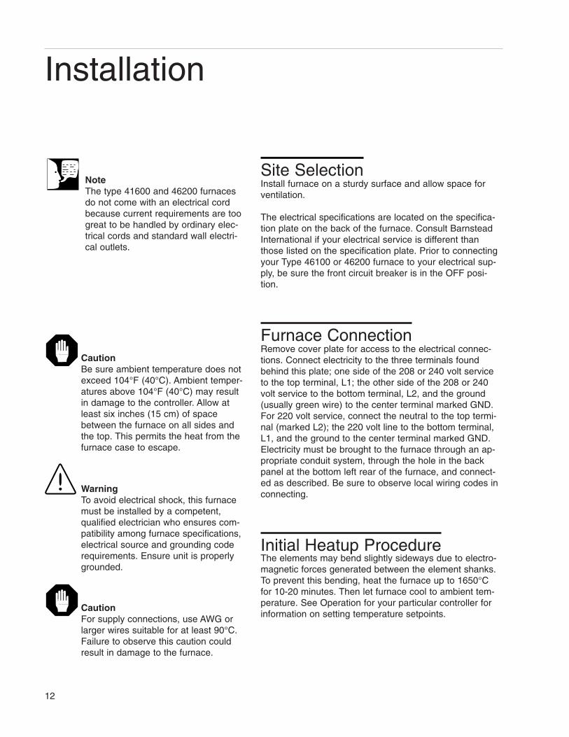
Site SelectionInstall furnace on a sturdy surface and allow space forventilation.
The electrical specifications are located on the specifica-tion plate on the back of the furnace. Consult BarnsteadInternational if your electrical service is different thanthose listed on the specification plate. Prior to connectingyour Type 46100 or 46200 furnace to your electrical sup-ply, be sure the front circuit breaker is in the OFF posi-tion.
Furnace ConnectionRemove cover plate for access to the electrical connec-tions. Connect electricity to the three terminals foundbehind this plate; one side of the 208 or 240 volt serviceto the top terminal, L1; the other side of the 208 or 240volt service to the bottom terminal, L2, and the ground(usually green wire) to the center terminal marked GND.For 220 volt service, connect the neutral to the top termi-nal (marked L2); the 220 volt line to the bottom terminal,L1, and the ground to the center terminal marked GND.Electricity must be brought to the furnace through an ap-propriate conduit system, through the hole in the backpanel at the bottom left rear of the furnace, and connect-ed as described. Be sure to observe local wiring codes inconnecting.
Initial Heatup ProcedureThe elements may bend slightly sideways due to electro-magnetic forces generated between the element shanks.To prevent this bending, heat the furnace up to 1650°Cfor 10-20 minutes. Then let furnace cool to ambient tem-perature. See Operation for your particular controller forinformation on setting temperature setpoints.
12
Installation
NoteThe type 41600 and 46200 furnacesdo not come with an electrical cordbecause current requirements are toogreat to be handled by ordinary elec-trical cords and standard wall electri-cal outlets.
CautionBe sure ambient temperature does notexceed 104°F (40°C). Ambient temper-atures above 104°F (40°C) may resultin damage to the controller. Allow atleast six inches (15 cm) of spacebetween the furnace on all sides andthe top. This permits the heat from thefurnace case to escape.
WarningTo avoid electrical shock, this furnacemust be installed by a competent,qualified electrician who ensures com-patibility among furnace specifications,electrical source and grounding coderequirements. Ensure unit is properlygrounded.
CautionFor supply connections, use AWG orlarger wires suitable for at least 90°C.Failure to observe this caution couldresult in damage to the furnace.

Observe the following warnings before operating yourfurnace.To avoid electrical shock, this furnace must:
1. Be installed by a competent, qualified elec-trician who insures compatibility among fur-nace specifications, electrical source andgrounding code requirements.
2. Always be disconnected from the electricalsupply prior to maintenance and servicing.
To avoid personal injury:1. Do not stand directly in front of the chamber
without wearing a heat resistant face shield,gloves and apron.
2. Do not operate or clean furnace withoutproper eye protection.
3. Do not use in the presence of flammable orcombustible materials; fire or explosion mayresult. This device contains componentswhich may ignite such materials.
4. Refer servicing to qualified personnel.
5. Caution: Hot Surface. Avoid Contact.
6. To AVOID EYE DAMAGE in operating orcleaning furnace, proper eye protectionmust be worn.
7. To AVOID BURNS, do not stand directly infront of the chamber without wearing a heatresistant face shield, gloves and apron.
8. To AVOID FIRE, do not place combustiblematerials where exposed to heat from opendoor.
13
General Operation of Furnace
Hot SurfaceCaution: Hot Surface. Avoid contact.

Power SwitchControls power to the furnace. Switch to the “ON” positionto energize the elements and the controller.
Cycle Indicator (OP1)The amber cycle light will illuminate when electricity isbeing supplied to the elements.
Circuit BreakerA double pole circuit breaker is located at the bottom ofthe control section. It serves to turn electricity ON andOFF and to protect the electrical circuit.
FansThe fans, located in the rear of the heating section andthe control section, will run continuously as long as elec-tricity is supplied to the furnace, even when the furnacepanel circuit breaker is OFF. This serves to remove resid-ual heat after the furnace is turned OFF so the heat doesnot cause damage to the controls.
ControllersYour furnace’s controller consists of a microprocessorbased three-mode (Proportional, Integral, Derivative), pro-grammable control with over temperature protection andappropriate output switching devices to control the fur-nace. The digital readout continuously displays chamber(upper display) and setpoint (lower display) temperaturesunless the SCROLL button or PAGE button is depressed.
14
GENERAL OPERATION OF FURNACE
CautionRemember that when the powerswitch is “ON,” the furnace will beginto heat to the setpoint temperature thatwas previously set in the controller.
CautionIf the electrical supply must be discon-nected from the furnace at any time,be sure the chamber temperature is500°C or less before doing so.
NoteWhen performing operations on thecontroller, remember that if youdepress and release either the PAGE,SCROLL, UP or DOWN buttons andmore than 8 seconds elapse beforethe buttons are used again, the dis-play screen will automatically switchback to displaying setpoint tempera-ture. If this happens, you will have tostep through each parameter untilyou reach the point at which the inter-ruption occurred. The parameter val-ues you adjusted earlier, however, willnot be lost or altered.

Accessing Controller ParametersTo enter the main list of controller parameters, press andrelease the PAGE button until you reach the desired pa-rameter. To scroll through the desired parameter, press andrelease the SCROLL button. within the main list, press andrelease the SCROLL button. To quickly advance betweenparameters, hold the PAGE or SCROLL button down.
15
GENERAL OPERATION OF FURNACE

8 Segment, 4-Program and 20-Program Models
Buttons and IndicatorsOP1 (Output 1): illuminates when the heating output of thetemperature controller is on.
AUTO/MAN (Auto/Manual Mode): when the controller is inthe automatic mode the output automatically adjusts to keepthe temperature or process value at the setpoint. The “AUTO”light will illuminate. The manual mode has been disabledthrough factory configuration. Call Customer Service for fur-ther information.
RUN/HOLD (Run/Hold button):• Starts a program when pressed once—RUN light
illuminates.
• Holds a program when pressed again—HOLD lightilluminates.
• Cancels hold and continues running when pressedagain—HOLD light is off and RUN light illuminates.
• Exits a program when the button is held down fortwo seconds—RUN and HOLD lights are off.
• At the end of a program the RUN light will flash.
• During holdback the HOLD light will flash.
PAGE button: allows you to choose a parameter from a listof parameters.
SCROLL button: allows you to choose a parameter within alist of parameters.
UP button: allows you to raise a value in the lower display.
DOWN button: allows you to decrease the value in the lowerdisplay.
16
Operation

Controller ParametersHome Display°C: measured temperature in Celsius. Temperature unitscan not be changed without entering the configuration.Contact Customer Service if a different temperature unit isrequired.
OP: % output power demand; displayed in lower display(cannot be changed).
C.id: Controller identification number.
PrG: Program number (displayed when a program is run-ning.
IdHi: Deviation High Alarm
tunE: One-shot autotune enable.
run LiSt (Program Run List)
PrG: Currently running program (only used on multi-pro-gram models)
StAt: Displays the program status [OFF, run (runningactive program), hoLd (program on hold), HbAc (waiting forprocess to catch up), End (program completed)] in thelower display. The controller will default to “OFF.”
PSP: Programmer setpoint temperature (displayed when aprogram is running).
CYC: Number of cycles remaining in program (displayedwhen a program is running).
SEG: Active segment number (displayed when a programis running).
StYP: Active segment type (displayed when a program isrunning).
SEG.t: Remaining segment time in segment units (dis-played when a program is running).
tGt: Target setpoint.
rAtE: Ramp rate (only if rate segment).
PrG.t: Program time remaining in hours (displayed when aprogram is running).
17
OPERATION

FASt: Fast run through program (no/YES). The controller willdefault to “no.”
out.n: Even output states (OFF/ON), only used on multi-pro-gram models.
SYnc: Synchronization (no/YES), only used on multi-programmodels.
SEG.d: Flash active segment type in the lower display of thehome display (no/YES). The controller will default to “no.”
ProG LiSt (Program Edit List)PrG.n: Press the UP or DOWN ARROW to select the pro-gram number (program number will be displayed in lower dis-play). Only used on multi-program models.
Hb: Press the UP or DOWN ARROW to select the holdbacktype [OFF (disables holdback), Lo (deviation low holdback),Hi (deviation high holdback) or bAnd (deviation band hold-back)] for the entire program. The controller will default to“OFF.”
Hb.U: Press the UP or DOWN ARROW to select the hold-back value (in display units).
rmP.U: Press the UP or DOWN ARROW to toggle betweenramp units (SEc, min or Hour). Controller will default to “SEc.”
dwL.U: Press the UP or DOWN ARROW to toggle betweendwell units (SEc, min or Hour). Controller will default to “SEc.”
Cyc.n: Press the UP or DOWN ARROW to set the number ofprogram cycles (1 to 999 or cont). The controller will default to“cont.”
SEG.n: Press the UP or DOWN ARROW to select the seg-ment number (1 -16).
tYPE: Press the UP or DOWN ARROW to select the segmenttype [End (end of program), rmP.r = ramp rate (ramp to aspecified setpoint at a set rate), rmp.t = ramp time (ramp to aspecified temperature in a set time), dwEll (to maintain a con-stant temperature for a set time), StEP (climb instantaneouslyfrom current to specified temperature), cALL (to call a pro-gram as a subroutine, available only on multi-program mod-els)]. The controller will default to “End.” Other parameters
18
OPERATION

used with tYPE include; tGt target setpoint), Rate (rate oftemperature increase) and dur (time to target setpoint ortime to dwell).
End.t: End of program.
AL LiSt (Alarm List)IdHi: Deviation High Alarm.
Atun LiSt: (Autotune List)tunE: One-shot autotune enable.
drA: Adaptive tune enable.
drA.t: Adaptive tune trigger level in display units. Range =1 to 9999.
Pid LiStG.SP (Gain Setpoint): If gain scheduling has beenenabled this parameter sets the PV (process value) belowwhich Pid1 (proportional band/integral time/derivative time)is active and above which Pid2 is active.
Pb: Proportional band in display units. (SEt 1)
ti: Integral time in seconds. (SEt 1)
td: Derivative time in seconds. (SEt 2)
Pb2: Proportional band. (SEt 2)
ti2: Integral time in seconds. (SEt 2)
td2: Derivative time in seconds. (SEt 2)
SP LiSt (Setpoint List)SP 1: Setpoint one value.
cmS LiSt (Comms List)Addr: Communications address.
ACCS LiSt (Access List)codE: Access password. Not needed for normal operation. Call Customer Service if configuration isrequired.
19
OPERATION

AlarmsThe controller will flash an alarm message in the home dis-play if an alarm condition is detected.FSL: PV full scale low alarm.
FSH: PV full scale high alarm.
dEv: PV deviation band alarm.
ldHi: PV deviation high alarm.
ldLo: PV deviation low alarm.
LCr: load current load alarm.
HCr: load current high alarm.
S.br: Sensor break: check that sensor is connected correctly.
L.br: Check that the heating circuits are working properly.
Ld.F: Load Failure: indication of either an open or short solidsate relay, a blown fuse, missing supply or open circuitheater.
SSr.F: Solid sate relay failure indications in a solid state relay:indicates either an open or short circuit in the SSR.
Htr.F: Heater failure: Indication that there is a fault in theheating circuit: indicates either a blown fuse, missing supplyor open circuit heater.
20
OPERATION

Basic OperationWhen the controller is turned “ON,” it will perform a shortself-test and then change to the HOME DISPLAY. TheHOME DISPLAY shows the measured temperature(process value) in the upper display and the desired value(setpoint) in the lower display.
To Operate the Controller as aSingle Setpoint Controller
1. Switch the circuit breaker to the “ON” position.The setpoint temperature presently set in the con-troller will appear in the lower display. (The upperdisplay indicates the actual chamber tempera-ture.)
2. To change the setpoint, press the UP or DOWNbutton until the desired setpoint value is dis-played; then release the button.
3. The furnace will begin to heat if the new setpointtemperature is higher than the present chambertemperature.
Programming the ControllerThe controller is capable of varying temperature or processvalue with time through programming. A program is storedas a series of ramp and dwell segments and can be runonce, repeated a set number of times or run continuously.
To create a customized program using the controllerparameters listed under “Controller Parameters” beginningof this section, follow the procedures outlined in the pro-ceeding sections of this manual.
Creating a New Program or Editing anExisting Program (Multi-program ModelsOnly)The same steps are used when creating a new programand editing an existing program with the exception beingthat a new program starts with all its segments set to Endin the tYPE parameter. Temporary changes can be made
21
OPERATION
NoteThe controller will return to the HOMEdisplay if left idle for more than a fewseconds.
NoteOnce the desired parameter has beenselected, depressing either the UP orDOWN button will cause the parameterto be replaced with the new value. Anyfurther use of the UP or DOWN buttonswill change the parameter value. In allcases, the value shown on the displayis the current working value of thatparameter.

to these parameters when the program is in the hold statebut permanent changes must be made in the reset state.Follow the steps below to create or edit a program.
1. Press the PAGE button until you reach the pro-gram list (ProG LiSt).
2. Press the SCROLL button until display reads,“PrG.n.”
3. Press the UP or DOWN button to select a num-ber for a new program or to edit an existing pro-gram.
HoldbackHoldback consists of a value and a type. If the measuredvalue lags behind the setpoint by an undesirable amountduring a ramp or dwell, the holdback feature can be usedto freeze the program at its current state (the HOLD lightwill flash). The amount of the actual temperature mayvary from the setpoint before the holdback takes effect.The program will resume when the error comes within theholdback value.
Holdback TypeThe holdback type is set when creating a new program.Any of the four different holdback types listed below maybe chosen:
OFF: holdback is disabled.
Lo (Deviation Low Holdback): holds the program backwhen process variable deviates below the setpoint bymore than the holdback value.
Hi (Deviation High Holdback): holds the program backwhen process variable deviates above the setpoint bymore than the holdback value.
bAnd (Deviation Band Holdback): combines the fea-tures of the high and low deviation holdback in that itholds the program back when the process variable devi-ates above or below the setpoint by more than the hold-back value.
22
OPERATION
NoteThe holdback type only appearswhen holdback has been selected forthe entire program.

To set the holdback type:1. Press the PAGE button until you reach the pro-
gram list (ProG LiSt).
2. Press the SCROLL button until display reads,“Hb.”
3. Press the UP or DOWN button to toggle between“bAnd, Hi, Lo and OFF.”
Holdback ValueTo set the holdback value:
1. Press the PAGE button until you reach the pro-gram list (ProG LiSt).
2. Press the SCROLL button until display reads,“Hb.U.”
3. Press the UP or DOWN button to enter a hold-back value.
Setting Ramp UnitsRamp units are time units which are used in “rmP.r” seg-ments (ramp to a setpoint at degrees per second, minuteor hour) and “rmP.t” segments (ramp to setpoint in a specif-ic amount of time). See “Setting the Segment Type” for anexplanation on hoe to set a ramp segment.
1. Press the PAGE button until you reach the pro-gram list (ProG LiSt).
2. Press the SCROLL button until display reads,“rmP.U.”
3. Press the UP or DOWN button to toggle betweenseconds, minutes and hours.
Setting Dwell UnitsDwell units are time units which are used in “dwELL” seg-ments (amount of time to remain at a specific temperature). See “Setting the Segment Type” for an explanation onhow to set a dwell segment.
1. Press the PAGE button until you reach the pro-gram list (ProG LiSt).
2. Press the SCROLL button until display reads,“dwL.U.”
3. Press the UP or DOWN button to togglebetween seconds, minutes and hours.
23
OPERATION
NoteThe value set in this parameter isalways for the entire program.

Setting the Number of CyclesSet the number of times a group of segments or pro-grams are to be repeated by following the steps listedbelow.
1. Press the PAGE button until you reach the pro-gram list (ProG LiSt).
2. Press the SCROLL button until displayreads,”CYC.n.”
3. Press the UP or DOWN button to select thenumber of cycles you want to run; or, press theDOWN button to select “cont.” so the programwill run continuously.
Setting the Segment NumberA program is set up by defining the characteristics of eachindividually selected number. To select a program num-ber, follow the steps listed below.
1. Press the PAGE button until you reach the pro-gram list (ProG LiSt).
2. Press the SCROLL button until display reads,“SEG.n.”
3. Press the UP or DOWN button to select thesegment number.
Setting the Segment TypeThere are five segment types. Proceed with the followingsteps according to the type of segment you have select-ed.
rmP.r (Ramp)To ramp linearly at at set rate to a specified temperature:
1. Press the PAGE button until you reach the pro-gram list (ProG LiSt).
2. Press the SCROLL button until displayreads,”tYPE.”
3. Press the UP or DOWN button until displayreads, “rmP.r.”
24
OPERATION
NoteThe program ramp rate is designed toreduce the heatup rate or cooling ratethat the furnace normally exhibits.When not using this feature, the fur-nace will operate at its maximumheating and cooling capability.
NoteWhen the program ramp has ended orhas been reset, the furnace will contin-ue to maintain setpoint temperature. Itwill not cool to ambient temperatureunless setpoint is set to ambient tem-perature by the program or by theoperator.

4. Press the SCROLL button until display reads“Hb.”
5. Press the UP or DOWN button to toggle between“bAnd, Hi, Lo and OFF.”
6. Press the SCROLL button until display reads,“tGt.”
7. Press the UP or DOWN button to set a target set-point.
8. Press the SCROLL button until displayreads,”rAtE.”
9. Press the UP or DOWN button to select a valuein ramp units (seconds, minutes or hours; set inthe “rmP.U” parameter).
rmP.tTo ramp to a specified temperature at at set time:
1. Press the PAGE button until you reach the pro-gram list (ProG LiSt).
2. Press the SCROLL button until display reads,“tYPE.”
3. Press the UP or DOWN button until displayreads, “rmP.t.”
4. Press the SCROLL button until display reads,“tGt.”
5. Press the UP or DOWN button to set a target set-point.
6. Press the SCROLL button until display reads,“dur.”
7. Press the UP or DOWN button to select a time inramp units (seconds, minutes or hours; set in the“rmP.U” parameter.
dwEllTo maintain a constant temperature for a specified time:
1. Press the PAGE button until you reach the pro-gram list (ProG LiSt).
2. Press the SCROLL button until display reads,“tYPE.”
25
OPERATION

3. Press the UP or DOWN button until displayreads, “dwEll.”
4. Press the SCROLL button until display reads,“dur.”
5. Press the UP or DOWN button to select a timein dwell units (seconds, minutes or hours; setin the “dwL.U” parameter).
StEPTo climb instantaneously from the current temperature toa specified temperature.
1. Press the PAGE button until you reach the pro-gram list (ProG LiSt).
2. Press the SCROLL button until display reads,tYPE.”
3. Press the UP or DOWN button until the displayreads, “StEP.”
4. Press the SCROLL button until display reads,“tGt.”
5. Press the UP or DOWN button to set a targetsetpoint.
cALL (Running Multiple Programs)To call a program as a subroutine:If you want to run multiple programs, you can program thecontroller to “call” or link one program to another. Thismakes it possible to run one program at any time duringanother program and also return to the original program ifdesired.
1. Press the PAGE button until you reach the pro-gram list (ProG LiSt).
2. Press the SCROLL button until display reads,“tYPE.”
3. Press the UP or DOWN button until displayreads, “cALL.”
26
OPERATION

4. Press the SCROLL button until display reads,“PrG.n.”
5. Press the UP or DOWN button to select aprogram number to be linked.
6. Press the SCROLL button until display reads,“CYC.n.”
7. Press the UP or DOWN button to select thenumber of cycles the linked program is to berun.
EndTo end or repeat a program:
1. Press the PAGE button until you reach theprogram list (ProG LiSt).
2. Press the SCROLL button until display reads,“tYPE.”
3. Press the UP or DOWN button until displayreads, “End.”
4. Press the SCROLL button until display reads,”End.t.”
5. Press the UP or DOWN button to togglebetween “dwEll” (an indefinite dwell), “S OP”(End Segment Output Power) and “rSET”(reset).
Setting the Target Setpoint1. Press the PAGE button until you reach the
program list (ProG LiSt).
2. Press the SCROLL button until displayreads, “tGt.”
3. Press the UP or DOWN button to set thetarget setpoint temperature.
27
OPERATION
CautionMinimize operation of furnace under800°C. Element life is reduced whenoperating below 800°C because the protective layer of silica glass takeslonger to form.

Running a Program1. Press the PAGE button until you reach the run
list (run LiSt).
2. Press the SCROLL button until display reads,“PrG.”
3. Press the UP or DOWN button to select theprogram number you want to run.
4. Press the RUN/HOLD button once to start theprogram. (The RUN light will illuminate.)
Holding a ProgramTo put a running program on hold, press the RUN/HOLDbutton. (The HOLD light will illuminate.)
Cancelling a ProgramTo cancel a program, hold the RUN/HOLD button downuntil the RUN and HOLD lights go off.
Tuning your FurnaceThe purpose of tuning your furnace is to match the char-acteristics of your controller to the characteristics of theprocess being controlled. Good control is evidenced by:stable, straight-line control of the setpoint temperaturewith no fluctuations; No overshoot or undershoot of thesetpoint temperature; Rapid restoration of the setpointtemperature when external disturbances cause deviationsfrom the setpoint.
Gain SchedulingGain scheduling is the automatic transfer of controlbetween to sets of PID values. The 2408 controller doesthis at a presettable process value. Gain scheduling isused for difficult control processes which show largechanges in their response time or sensitivity at high or lowtemperatures, or when heating or cooling.
28
OPERATION
NoteAll of the controllers have automatictuning features which install optimumtuning parameters to give the besttemperature accuracy. No manualloading of tuning parameters is need-ed. We recommend that you tune thefurnace to your specific application toobtain the best results. To provide thebest temperature accuracy possible,use these features when you installyour furnace and whenever youchange your application or procedure.
NoteDisplay will flash “tu.ER” if an erroroccurs during tuning. To clear theerror and restart tuning, simultane-ously press the PAGE and SCROLLbuttons and follow the steps outlinedin “Autotuning.”

The G.SP gain schedule Setpoint) is factory set at1210°C. If tuning within 200°C above or below theG.SP. you must adjust your G.SP value up or down tomaintain at least a 200°C span between the G.SP andthe SP.
Setting the Transfer PointIf gain scheduling has been enabled, “G.SP will appearat the top of the PID list. This sets the value at whichthe transfer will occur. When the process value isbelow this level, PID1 will be active and when it isabove, Pid2 will be active. Set a value between thecontrol regions that show the greatest change toachieve the best point of transfer.
TuningThe two sets of PID values can be manually set orautomatically tuned. To tune automatically, you musttune above and below the transfer point G.SP. If theprocess value is below the transfer point G.SP, the cal-culated values will automatically be inserted into thePID1 set and if the process value is above G.SP, thecalculated values will automatically be inserted into thePID2 set.
AutotuningThe Autotune feature automatically sets up the initialvalues in the control parameters to suit new processconditions by putting the controller into a one time,self-tuning mode. For successful tuning to occur, it isbest to preheat your furnace to 50°C before proceedingwith the following steps.
To tune your furnace using autotuning:1. Load your furnace with a load similar to your
normal load and close the door.
2. Set the setpoint temperature.
3. Press the PAGE button until the displayreads, “Atun LiSt.”
4. Press the SCROLL button until “tunE OFF”is displayed.
5. Press the UP or DOWN button to select“on.”
29
OPERATION
NoteThe B thermocouple will not read accu-rately below 250°C.
NoteTo stop the tuning function, simultane-ously press the PAGE and SCROLLbuttons.

6. Simultaneously press the PAGE and SCROLLbuttons to return to the HOME DISPLAY. Thedisplay will flash “tunE” while tuning is inprogress.
Adaptive TuningAdaptive tuning continuously evaluates tuning parame-ters. Adaptive tuning automatically installs new values ifbetter accuracy is possible. Adaptive tuning should beused when the characteristics of a process change due toload or setpoint changes or, in a process that can nothandle the oscillation caused by a one-shot tune.
To tune your furnace using adaptive tuning:1. Load your furnace with a load characteristic of
those you intend to heat in it.
2. Press the PAGE button until display reads, “AtunLiSt.”
3. Press the SCROLL button until “drA OFF” isdisplayed.
4. Press the UP or DOWN button to select “on.”
30
OPERATION
During tuning, the lower display flashes between “tunE”and the setpoint temperature. The setpoint temperaturecan be changed during tuning by pressing the UP orDOWN buttons. The lower display will continue to flashuntil the tuning is completed. Be sure to use care in loading and unloading the fur-nace chamber. Molybdenum disilicide heating elementsare extremely fragile and can crack or break with just aslight bump. Be sure not to block the flow of radiantheat from the heating elements to the thermocouple.The thermocouple must be able to respond directly tothe heating elements. Failure to observe this will permitthe heating elements to overheat and possibly burnout. Poor temperature control can also result fromimproper loading.
Because of the possibility of erosion of the insulationon the floor of the furnace chamber, a separate hearthplate should be used when possible.
In general, space should be left on all sides of a loador on all sides of individual components of a load sothat heat can penetrate through the surfaces. The loadshould not occupy more than two-thirds of the insidedimensions of the chamber.
The extent to which a furnace may be loaded dependsupon such factors as operating temperature, desiredaccuracy, and type of material. A furnace may beloaded more heavily at lower temperatures, if highestaccuracy is not needed, and if the material of the loadabsorbs heat easily.
Furnace AtmospheresThis furnace is designed to be used to 1700°C in pureair only. It may be used with nitrogen, argon, or heliumatmospheres to 1600°C. Reducing atmospheres arenot recommended.
The heating elements in this furnace are attacked byfluorine, chlorine, sodium and potassium compoundsand also by molten metals. This furnace may be usedfor metal melting if care is taken not to splash moltenmetal on the heating elements.
31
Furnace Loading

WarningThis warning is presented for compliance with CaliforniaProposition 65 and other regulatory agencies and onlyapplies to the insulation in this product. This product con-tains refractory ceramic, refractory ceramic fiber or fiber-glass insulation, which can produce respirable dust orfibers during disassembly. Dust or fibers can cause irrita-tion and can aggravate preexisting respiratory diseases.Refractory ceramic and refractory ceramic fibers (afterreaching 1000°C) contain crystalline silica, which cancause lung damage (silicosis). The International Agencyfor Research on Cancer (IARC) has classified refractorceramic fiber and fiberglass as possibly carcinogenic(Group 2B), and crystalline silica as carcinogenic tohumans (Group 1).
The insulating materials can be located in the door, thehearth collar, in the chamber of the product or under thehot plate top. Tests performed by the manufacturer indi-cate that there is no risk of exposure to dust or respirablefibers resulting from operation of this product under nor-mal conditions. However, there may be a risk of exposureto respirable dust or fibers when repairing or maintainingthe insulating materials, or when otherwise disturbingthem in a manner which causes release of dust or fibers.By using proper handling procedures and protectiveequipment you can work safely with these insulatingmaterials and minimize any exposure. Refer to the appro-priate Material Safety Data Sheets (MSDS) for informa-tion regarding proper handling and recommended protec-tive equipment. For additional MSDS copies, or additionalinformation concerning the handling of refractory ceramicproducts, please contact the Customer Service Depart-ment at Barnstead International at 1-800-553-0039.
General Cleaning InstructionsWipe exterior surfaces with lightly dampened cloth con-taining mild soap solution.
A few simple procedures will help insure that your furnacewill give you long service.
1. Keep the chamber clean; this furnace is capa-ble of achieving temperatures which will causevaporization of many materials. In turn, thesevapors can react with the heating elements,
32
Preventive Maintenance
WarningTo avoid electrical shock, this furnacemust always be disconnected from theelectrical supply prior to maintenanceand servicing. Refer servicing to quali-fied personnel.

the insulation, or other materials you haveplaced in the chamber. In many instancesthis reaction is detrimental to operation.
2. Clean exterior surfaces with lightly damp-ened cloth containing mild soap solution
3. Occasionally check the electrical connectionsin the control section. Repeated heating andcooling can cause terminals to loosen.
4. The type B thermocouple used in this fur-nace is matched to the temperature con-troller. It is possible that its calibration candrift, particularly when operated near theupper temperature limit, and especially inthe presence of contaminants. It is a goodidea to inspect it at regular intervals or whenits accuracy is suspect.
5. Check the cooling fans at regular intervalsto be sure they are functioning properly andare not obstructed.
The following pages are intended to help you resolvefunctional problems with your furnace.
Barnstead International is always available to assistyou with problems. If this guide does not direct you toyour specific problem, call Barnstead International at 1-800-553-0039.
33
PREVENTIVE MAINTENANCE

PROBLEM POSSIBLE CAUSES CORRECTIVE ACTION
Inaccurate temperatures. Contaminated thermocouple. Replace thermocouple.
Repeated element burnout. Continuous operation Do not continuouslybelow 800°C. operate below 800°C.
Contact Barnstead International.Heating element contamination.
“OR” displayed. Open thermocouple. Replace thermocouple.
Slow heatup. Operating 240V furnace Increase voltage toon 208V supply. proper level.
Furnace chamber overloaded. Lighten load.
Building or laboratory Fuses or breakers not Install service line of sufficientmain fuses blow or properly rated to size to match furnacecircuit breakers trip. furnace electrical electrical requirements. Contact
requirements. Barnstead International for assistance.
Other errors displayed. Contact Barnstead International.
34
Troubleshooting

WarningThis warning is presented for compliance with Califor-nia Proposition 65 and other regulatory agencies andonly applies to the insulation in this product. This prod-uct contains refractory ceramic, refractory ceramic fiberor fiberglass insulation, which can produce respirabledust or fibers during disassembly. Dust or fibers cancause irritation and can aggravate preexisting respira-tory diseases. Refractory ceramic and refractoryceramicfibers (after reaching 1000°C) contain crystalline silica,which can cause lung damage (silicosis). The Interna-tional Agency for Research on Cancer (IARC) has clas-sified refractory ceramic fiber and fiberglass as possi-bly carcinogenic (Group 2B), and crystalline silica ascarcinogenic to humans (Group 1).
The insulating materials can be located in the door, thehearth collar, in the chamber of the product or underthe hot plate top. Tests performed by the manufacturerindicate that there is no risk of exposure to dust or re-spirable fibers resulting from operation of this productunder normal conditions. However, there may be a riskof exposure to respirable dust or fibers when repairingor maintaining the insulating materials, or when other-wise disturbing them in a manner which causesrelease of dust or fibers. By using proper handling pro-cedures and protective equipment you can work safelywith these insulating materials and minimize any expo-sure.Refer to the appropriate Material Safety Data Sheets(MSDS) for information regarding proper handling andrecommended protective equipment. For additionalMSDS copies, or additional information concerning thehandling of refractory ceramic products, please contactthe Customer Service Department at BarnsteadInternational at 1-800-553-0039.
To avoid premature burnout of a replacement heatingelement, be sure that the insulation tail supplied withthe replacement element is inserted between the twolegs of the element as shown in the drawing. Also besure that the heating element projects sufficiently intothe chamber. Insert element until welded portion(where large diameter meets small diameter) projectsapproximately 1/4" into inside of furnace chamber.
35
Maintenance and Servicing
WarningTo avoid electrical shock, this furnacemust always be disconnected from theelectrical supply prior to maintenance andservicing. Do not clean clean furnacewithout proper eye protection. Refer serv-icing to qualified personnel.

To replace a heating element(refer to Fig. 1A):
1. Remove top cover from heating chamber sideof furnace.
2. Remove the clips holding the connector cable(4) to the defective heating element. Unwrapthe connector cable from the element.
3. Slide the heating element with element ceram-ic holder attached upward, out of the slot in theinsulation. Save the blanket insulation forreuse.
4. Remove the element ceramic holder, noting itsexact position on the heating element.
5. Fasten the element ceramic holder on the newelement in exactly the same position it was onthe old element.
6. Begin inserting the new element with elementceramic holder attached into the slot in theinsulation; stop when there is just enough roomleft to insert the new element insulation.
7. Continue sliding the element with the elementinsulation tail into the slot. DO NOT FORCE -even slight pressure can fracture the heatingelement.
8. When the element ceramic holder is nearlyseated against the main insulation, check thetop of the element insulation tail. In its finalposition, the top should be about 1/8 inchbelow the surface of the main insulation.
9. Position the blanket insulation piece from stepc in the cavity over the insulation tail. Completeinsertion of the heating element until the ele-ment ceramic holder rests on top the maininsulation. Check the heating element on theinside of the chamber. The large diameter sec-tion of the element must be flush with or slight-ly projecting from the surface of the insulation
36
MAINTENANCE AND SERVICING
CautionTo avoid breakage of a replacementheating element, be sure that the slotinto which the replacement heatingelement slides is free of all debris sothat the element goes in very easily.Forcing an element into a slot, howev-er slightly, can result in its breakage.

(if not, reposition element ceramic holder).Carefully wrap the connector cable aroundthe element ends; fasten with clips. Replacetop cover.
To replace thermocouple:1. Remove top cover from the heating cham-
ber side of furnace.
2. Loosen diagonal screw holding ceramic con-nection block.
3. Lift connection block.
4. Loosen connection block screws holdingthermocouple; noting which side of block theside of the thermocouple with the coloredbead is connected to.
5. Remove thermocouple.
6. Install new thermocouple with colored beadin same position.
7. With thermocouple through the hole in theinsulation, replace block in its holder and re-tighten diagonal screw.
8. Turn furnace ON for a few minutes; check tobe sure the temperature displays upscale.
9. Replace cover.
37
MAINTENANCE AND SERVICING
Figure 1A: Element Replacement

38
Wiring Diagrams
FU
SE
AN
D H
OLD
ER
AR
E S
UP
PLI
ED
WIT
H C
UR
RE
NT
CO
NT
RO
LLE
R.
NO
TE
S:
HR
1
---
240
VO
LTS
T1
HR
2
RY
1
...20
8 V
OLT
SSW
1
HR
3
SE
RIE
S E
LEM
EN
TS
HR
4H
R5
HR
6
ALL
OT
HE
RM
OD
ELS
L2L1
-33
MO
DE
LS O
NLY
L2L1
12
76
5
34
ON
43
TE
10 A
+
EU
RO
TH
ER
M
I LIM
IT
12
-
2D 3C 3D3B3A
JB JE JFJC JD
AB
BLA
CK
V+
RE
D
V-
AC
VI
CB
1
DS
1
CN
2
M1
M2
TC
1
2B1C1B 2A1D1A
CN
1
2C
HF
LC
HB
HC
HE
HD
HA
N
LBLA
L
JAA
A
FL1
SG
INT
ER
NA
L C
OM
MU
NIC
AT
ION
CA
BLE
WIR
ING
CO
NT
RO
LLE
RC
ON
NE
CT
OR
2
3R
D7 TD
O B W
HD
HE
HF
F U S E
CN
1C
N2
CB
1
M1
M2
RY
1
T1
TC
1
DS
1
HR
1 to
HR
6
SW
1
CO
NT
RO
LLE
R, T
EM
PE
RA
TU
RE
CO
NT
RO
LLE
R, C
UR
RE
NT
CIR
CU
IT B
RE
AK
ER
FAN
FAN
CO
NTA
CT
OR
, ME
CH
AN
ICA
L
TR
AN
SF
OR
ME
RT
HE
RM
OC
OU
PLE
IND
ICA
TO
R L
AM
P
HE
AT
ING
ELE
ME
NT
DO
OR
SW
ITC
H
FL1
EM
I LIN
E F
ILT
ER
SW
X16
3
EL4
61X
1
PLX
90
TC
X5
TN
X79
RY
X62
FAX
7
FAX
7
SW
X54
CN
71X
68
CN
71X
65
SW
X16
3
EL4
61X
1
PLX
90
TC
X5
TN
X79
RY
X62
FAX
7
FAX
7
SW
X54
CN
71X
68
CN
71X
66C
N71
X67
CN
71X
68
SW
X54
FAX
7
FAX
7
RY
X62
TN
X79
TC
X5
PLX
90
EL4
61X
1
SW
X16
3
CN
71X
65
SW
X16
3
EL4
61X
1
PLX
90
TC
X5
TN
X79
RY
X62
FAX
7
FAX
7
SW
X54
CN
71X
68
CA
X10
5
CN
71X
66
CN
71X
68
SW
X54
FAX
7
FAX
7
RY
X62
TN
X79
TC
X5
PLX
90
EL4
61X
1
SW
X16
3
CA
X10
5C
AX
105
SW
X16
3
EL4
61X
1
PLX
90
TC
X5
TN
X79
RY
X62
FAX
7
FAX
7
SW
X54
CN
71X
68
CN
71X
67
DIA
GR
AM
CO
MP
ON
EN
T L
IST
PA
RT
NO
.D
ES
CR
IPT
ION
OU
R P
AR
T N
O. P
ER
MO
DE
L(S
)
F46
118C
MF
4611
0CM
F46
128C
MF
4612
0CM
F46
128C
M-7
5F
4612
0CM
-75
F46
110C
M-3
3F
4612
0CM
-33
F46
120C
M-3
3-75

39
WIRING DIAGRAMS
CO
NT
RO
LLE
R
3
WBO
HF
HE
HD
CO
NN
EC
TO
R
INT
ER
NA
L C
OM
MU
NIC
AT
ION
CA
BLE
WIR
ING
7
2
SG R
D TD
TE
10 A
34
43
ON
21
I LIM
ITEU
RO
TH
ER
M
21
56
7
FUSE
+-
1A 1B 1C 1D 2A 2B 2C 2D 3A 3B 3C 3DJFJEJDJCJBJAH
F
HE
HD
HC
HB
HA
V-
V+
VI
AC
AB
AA
LCLBLA
NL
HR
1H
R2
HR
3H
R4
HR
5H
R6
HR
7H
R8
SE
RIE
S E
LEM
EN
TS
DS
1
CB
1
M1
M2
M3
SW
1
BLA
CK
RE
D
TC
1
RY
1
T1
FL1
L1L2
2
08 V
OLT
S
240
VO
LTS
CN
2
CN
1
NO
TE
S:
FU
SE
AN
D H
OLD
ER
AR
E S
UP
PLI
ED
WIT
H C
UR
RE
NT
CO
NT
RO
LLE
R.
L1L2
-33
MO
DE
LS O
NLY
ALL
OT
HE
RM
OD
ELS
FL1
CN
1C
N2
CB
1
M1
M2
M3
RY
1
T1
TC
1
DS
1
HR
1 to
HR
8
SW
1
EM
I LIN
E F
ILT
ER
CO
NT
RO
LLE
R, T
EM
PE
RA
TU
RE
CO
NT
RO
LLE
R, C
UR
RE
NT
CIR
CU
IT B
RE
AK
ER
FAN
FAN
FAN
CO
NTA
CT
OR
, ME
CH
AN
ICA
L
TR
AN
SF
OR
ME
R
TH
ER
MO
CO
UP
LE
IND
ICA
TO
R L
AM
P
HE
AT
ING
ELE
ME
NT
DO
OR
SW
ITC
H
CA
X10
5
CN
71X
65
CN
71X
68
SW
X54
FAX
7
FAX
7
FAX
7
RY
X62
TN
X80
TC
X5
PLX
90
EL4
62X
1
SW
X16
3
FAX
7
SW
X16
3
EL4
62X
1
PLX
90
TC
X5
TN
X80
RY
X62
FAX
7
FAX
7
SW
X54
CN
71X
68
CN
71X
66
CA
X10
5
FAX
7
RY
X62
TN
X80
TC
X5
PLX
90
EL4
62X
1
SW
X16
3
CA
X10
5
CN
71X
67
CN
71X
68
SW
X54
FAX
7
FAX
7
FAX
7
SW
X16
3
EL4
62X
1
PLX
90
TC
X5
TN
X80
RY
X62
CN
71X
65
FAX
7
FAX
7
SW
X54
CN
71X
68
FAX
7
RY
X62
TN
X80
TC
X5
PLX
90
EL4
62X
1
SW
X16
3
CN
71X
66
CN
71X
68
SW
X54
FAX
7
FAX
7
FAX
7
SW
X16
3
EL4
62X
1
PLX
90
TC
X5
TN
X80
RY
X62
CN
71X
67
FAX
7
FAX
7
SW
X54
CN
71X
68
PA
RT
NO
.D
ES
CR
IPT
ION
PA
RT
NO
. PE
R M
OD
EL(
S)
F46
230C
M-3
3F
4624
0CM
-33
F46
240C
M-3
3-75
F46
230C
MF
4623
8CM
F46
240C
MF
4624
8CM
F46
240C
M-7
5F
4624
8CM
-75
DIA
GR
AM
CO
MP
ON
EN
T L
IST

Description SERIES 1140 SERIES 1141(Chamber) Small (Models) Large (Models)
(6"X6"X6") (10"X10"X10")Circuit breaker switch SWX54 SWX54Connector cable 30" long CE557X1 (2 req’d) CE557X1 (1 req’d)Connector cable 36" long CE558X1 (1 req’d)Current controller CN71X68 CN71X68Controller (8 segment) CN71X65 (F46110 types) CN71X65 (F46230 types)Controller (4 program) CN71X66 (F46120 types) CN71X66 (F46240 types)Controller (20 Program) CN71X67 (F46120CM-75) CN71X67 (F46240CM-75)
Elements EL461X1 (6 req’d) EL462X1 (8 req’d)Element ceramic holder HRX2 (6 req’d) HRX2 (8 req’d)Element connector clips CEX135 (12 req’d) CEX135 (16 req’d)Element connector cable 4" lg CE461X1 (4 req’d) CE461X1 (6 req’d)Element connector cable 10" Ig CE461X3 Element connector cable 14" lg CE462X1 Element connector cable 19" lg CE462X2Element Insulation tail JN461X8 (6 req’d) JN461X8 (8 req’d)Fans FAX7 (2 req’d) FAX7 (3 req’d) Fuse, Thyristor, Fast Blow, 250V, 45 Amp FZX42 FZX42 Fuse Holder FZX62 FZX62 Hearth Plate PH461X1 PH462X1Injection Port w/plug JC633x1 JC633x1
& JC633X2 (plug) & JC633X2 (plug) Insulation - door JN461X3 JN462X4Insulation Kit - chamber JN461X9A JN462X7ARelay RYX62 RYX62Thermocouple TCX5 TCX5Thermocouple terminal block TRX137 TRX137 Transformer TNX79 TNX80
40
Replacement PartsWarningReplace fuses with the same type andrating.
NoteService on control units: contactBarnstead International(1-800-553-0039).

Please refer to the Specification Plate for the completemodel number, serial number, and series number whenrequesting service, replacement parts or in any corre-spondence concerning this unit. All parts listed hereinmay be ordered from the Barnstead International deal-er from whom you purchased this unit or can beobtained promptly from the factory. When service orreplacement parts are needed we ask that you checkfirst with your dealer. If the dealer cannot handle yourrequest, then contact our Customer ServiceDepartment at 563-556-2241 or 800-553-0039. Prior toreturning any materials to Barnstead International,please contact our Customer Service Department for a“Return Materials Authorization” number (RMA).Material returned without an RMA number will berefused.
41
Ordering Procedures

42

43

One Year Limited Warranty
Barnstead International (“BARNSTEAD”) warrants that if a product manufactured by Barnstead shall be free ofdefects in materials and workmanship for one (1) year from the first to occur of (i) the date the product is sold byBARNSTEAD or (ii) the date the product is purchased by the original retail customer (the “CommencementDate”). Except as expressly stated above, BARNSTEAD MAKES NO OTHER WARRANTY, EXPRESSED ORIMPLIED, WITH RESPECT TO THE PRODUCTS AND EXPRESSLY DISCLAIMS ANY AND ALL WARRANTIES,INCLUDING BUT NOT LIMITED TO, WARRANTIES OF DESIGN, MERCHANT ABILITY AND FITNESS FOR APARTICULAR PURPOSE.
An authorized representative of BARNSTEAD must perform all warranty inspections. In the event of a defectcovered by BARNSTEAD’s warranty, BARNSTEAD shall, as its sole obligation and exclusive remedy, provide freereplacement parts to remedy the defective product. In addition, for products sold by BARNSTEAD within the con-tinental United States or Canada, BARNSTEAD shall provide provide free labor to repair the products with thereplacement parts, but only for a period of ninety (90) days from the Commencement Date.
BARNSTEAD’s warranty provided hereunder shall be null and void and without further force or effect if there isany (i) repair made to the product by a party other than BARNSTEAD or its duly authorized service representa-tive, (ii) misuse (including use inconsistent with written operating instructions for the product), mishandling, con-tamination, overheating, modification or alteration of the product by any customer or third party or (iii) use ofreplacement parts that are obtained from a party who is not an authorized dealer of BARNSTEAD.
Heating elements, because of their susceptibility to overheating and contamination, must be returned to theBARNSTEAD factory and if, upon inspection, it is concluded that failure is due to factors other than excessivehigh temperature or contamination, BARNSTEAD will provide warranty replacement. As a condition to the returnof any product, or any constituent part thereof, to BARNSTEAD’s factory, it shall be sent prepaid and a prior writ-ten authorization from BARNSTEAD assigning a Return Materials Number to the product or part shall beobtained.
IN NO EVENT SHALL BARNSTEAD BE LIABLE TO ANY PARTY FOR ANY DIRECT, INDIRECT, SPECIAL, INCI-DENTAL, OR CONSEQUENTIAL DAMAGES, OR FOR ANY DAMAGES RESULTING FROM LOSS OF USE ORPROFITS, ANTICIPATED OR OTHERWISE, ARISING OUT OF OR IN CONNECTION WITH THE SALE, USEOR PERFORMANCE OF ANY PRODUCTS, WHETHER SUCH CLAIM IS BASED ON CONTRACT, TORT(INCLUDING NEGLIGENCE), ANY THEORY OF STRICT LIABILITY OR REGULATORY ACTION.
The name of the authorized Barnstead International dealer nearest you may be obtained by calling 1-800-446-6060 (563-556-2241) or writing to:
2555 Kerper BoulevardDubuque, Iowa 52001-9918 Phone: 563-556-2241 or 800-553-0039 Fax: 563-589-0516E-mail: [email protected]