Embed Size (px)
Citation preview

15th International LS-DYNA® Users Conference Constitutive Modeling
June 10-12, 2018 1
High Strain Rate Testing and Material Modeling of an
Anisotropic Glass Fiber Filled Polyetherimide
Sean Teller, Ph.D. Jorgen Bergstrom, Ph.D.
Veryst Engineering, Needham, MA
Abstract High strength composite polymers are often used in applications that require high impact strength and durability. Accurately characterizing the mechanical behavior for FE simulation requires testing the materials at high strain rates and may require multiple loading modes. Veryst Engineering has developed high-strain rate experimental facilities for testing all classes of polymers. We tested 30% glass-fiber filled Polyetherimide (PEI) at engineering strain rates from 1 x 10⁻³ to 1.2 x 10+3 s-1 in uniaxial tension and compression. All quasi-static tests (less than 1 s-1) were performed on standard universal test frames. High rate (1.2 x 10³ s-1) compression tests were performed on a Split Hopkinson Pressure Bar (SHPB), while high rate (50 to 2 x 10³ s-1) tension tests were performed on a custom-built drop tower. For tension tests, experiments were recorded with high speed digital video and strain was calculated with Digital Image Correlation (DIC). The material exhibits anisotropic small-strain response and anisotropic rate-dependent yield. We have developed and implemented in LS-DYNA® a nonlinear anisotropic elastic-viscoplastic user material, the Flow Evolution Network (FEN) model. The FEN is an advanced constitutive model designed to capture the behavior of a wide range of polymer materials, including filled thermoplastics. The model consists of one to four parallel networks composed of anisotropic Yeoh hyperelastic spring elements with power-law flow elements. The flow elements use an anisotropic Hill flow law to model material yield. The model can also incorporate changing flow resistance that evolves with plastic strain. The constitutive model was calibrated to the experimental data with a nonlinear search algorithm in MCalibration® from Veryst Engineering and captures the material response well. After constitutive model calibration was complete, the calibrated constitutive model was validated with a three-point bend test. The force-displacement data from the experiment matches the LS-DYNA FE predictions well.
Introduction
Since the introduction of polymeric materials, they have been widely used in impact applications. The low cost, weight, and high strength of composite polymers makes them attractive for use in many impact scenarios, including automotive, aerospace, consumer products and electronics, medical devices, and athletic equipment. Accurately modeling the mechanical response of the materials is paramount to accurate and reliable Finite Element (FE) simulations and requires experimental data that matches the intended use case.
The molecular structure of polymeric materials makes their mechanical response inherently rate-dependent. This increases the need for high strain-rate test methods that can be used to test a wide-range of materials at applicable strain rates (i.e. 1 s-1 to >1000 s-1). Although some experimental methods developed for metals can be used for stiff polymers, test methods designed specifically for polymers may be more appropriate [3,4]. For example, the Split Hopkinson Pressure Bar (SHPB) is widely used for characterizing stiff thermoplastics, but can be less suitable for soft polymer materials such as rubbers and foams [4]. The need for test methods deigned for polymeric materials has driven high-strain rate test method development at Veryst Engineering.
Selecting and calibrating a constitutive model to experimental data can also be challenging, as many
rate-dependent constitutive models available in commercial FE packages were developed for metals. These models (e.g. Johnson-Cook, isotropic hardening plasticity models) are not well-suited to capture the behavior of polymers, particularly unloading [1]. Advanced material models designed for polymers are increasingly available for use in commercial FE codes, though calibration may be difficult due to increased complexity and

15th International LS-DYNA® Users Conference Constitutive Modeling
June 10-12, 2018 2
the number of material parameters. We have developed an advanced constitutive model, the Flow Evolution Network (FEN) available in Veryst Engineering’s PolyUMod®, to capture the complex anisotropic elastic-viscoplastic response of polymer materials, including fiber filled composites [1, 6].
We demonstrate the features of the FEN model in the current work. We tested a 30% glass-fiber filled
Polyetherimide (PEI) material in uniaxial compression and uniaxial tension with applied strain rates from 0.001 s-1 to 1200 s-1. We then calibrated the FEN model, available as a user material model in LS-DYNA through Veryst Engineering’s PolyUMod, to the experimental data. The model captures the material response well, including the rate-dependency, anisotropy, and hysteresis. The calibrated model was then validated with a three-point bend test to ensure that the calibrated constitutive model captures more complicated multiaxial load cases. The test and simulation are in good agreement.
Materials and Methods
Glass-fiber filled PEI specimens were waterjet cut from 6.7 mm extruded sheet stock. Tension
specimens were cut in the flow direction (0°), as well as perpendicular to the flow direction (90°), and 45° to the flow direction. We performed low strain rate tests on ASTM D638 Type IV dogbones, and high strain rate tests on ASTM D638 Type V dogbones [2]. Compression samples were cut and tested through the thickness of the sheet; samples were 6.7 mm x 6.7 mm right circular cylinders.
Low strain rate tests were performed on an electromechanical universal load frame. We applied a
speckle pattern to the tension samples prior to testing for strain analysis using Digital Image Correlation (DIC). Sample strains were computed after the experiment with Correlated Solutions Vic-2D. We attached an extensometer to the load platens during compression testing to measure the sample strain.
We performed high-rate compression tests using a Split Hopkinson Pressure Bar (SHPB), Figure 1. The
system uses aluminum striker and transmission bars, and strain is measured with strain gauges attached to the bars. The stress-strain response was calculated similar to [8]. We performed high-rate tension tests on a custom-built drop tower shown in Figure 2 [4, 5]. The drop tower is capable of impact speeds over 4 m/s and can be used to test samples in tension, compression, and shear. Sample strain is measured using a high-speed camera (>75,000 fps), and a dynamic load cell measures force throughout the test. Stress and strain data are synced post-test using MATLAB®.
We calibrated the constitutive model to the experimental data using MCalibration® from Veryst Engineering. MCalibration performs single element FE simulations with the experimental strain history as the applied load, calculating the stress response of a candidate constitutive model. The difference between the experimental stress and the predicted stress from the model are compared, and a non-linear search algorithm minimizes the error by updating the material parameters with new candidate constitutive model parameters.
We performed a three-point bend constitutive model validation test that was not used to calibrate the
constitutive model. We performed the test on an electromechanical universal load frame, and the sample was speckle-patterned for DIC strain measurements. The validation test is a symmetric three-point bend test shown in Figure 3, with the sample orientation described in the figure. The span length between supports is 89 mm, and the load head has a diameter of 25 mm. The sample was loaded at 0.1 mm/s, and loadhead displacement was calculated using DIC on fiducial markers on the central loading roller.

15th International LS-DYNA® Users Conference Constitutive Modeling
June 10-12, 2018 3
Figure 1: Veryst Engineering's Split Hopkinson Pressure (Kolsky) Bar.
Figure 2: Veryst Engineering's custom-built drop tower.

15th International LS-DYNA® Users Conference Constitutive Modeling
June 10-12, 2018 4
Figure 3: Validation test setup and sample orientation. The 1-deirection is aligned with the material fibers.
Experimental Results
Applied strain history and stress history for an exemplar low strain-rate tension test are shown in Figure
4. We performed cyclic tests to capture the visco-plastic response of the material, including unloading and stress relaxation effects. We loaded samples to 0.75%, 1.5%, and 2.2% engineering strain, and held the samples for a 10 second stress relaxation segment at each strain level. The sample was unloaded to a small load after each stress relaxation segment. The material shows little stress relaxation during these hold periods. Figure 5 and Figure 6 present results for low-rate cyclic tension tests and high rate monotonic tension tests. Figure 5 presents tensile data from samples tested at three different orientations: 0° (flow direction), 90° (perpendicular to flow direction), and 45°. Figure 6 presents results showing the strain-rate dependence of the 90° samples. The high strain-rate test results have more noise in the data, particularly at low strains. This is due to the dynamic loading and sample inertia effects. This noise here is typical for stiff materials. Samples tested in other orientations show similar rate-dependence as the 90° samples.
Figure 4: Exemplar applied strain (left) and stress(right) history for a 0° tension test.

15th International LS-DYNA® Users Conference Constitutive Modeling
June 10-12, 2018 5
Figure 5: Cyclic tension test results at 0.001 s-1 in three directions.
Figure 6: Cyclic Tension tests on 90° samples at 0.001 s-1, 0.1 s-1, 100 s-1, and 200 s-1.

15th International LS-DYNA® Users Conference Constitutive Modeling
June 10-12, 2018 6
Figure 7 shows exemplar strain and stress history for a compression test at 0.1 s-1. We loaded samples to 5%, 10%, and 20% engineering strain with 10 second stress relaxation segments. The samples were unloaded to a small load after each stress relaxation segment. The material shows significant stress relaxation above 10% applied strain, as well as plastic deformation during unloading. Figure 8 presents data for compression tests at all strain rates. The material shows moderate rate-dependence, with test data between 0.001 s-1- and 1200 s-1. Cyclic experiments show significant hysteresis during unloading and reloading. All samples failed in compression, and results in Figure 7 and Figure 8 are truncated prior to sample failure.
Figure 7: Exemplar applied strain (left) and stress (right) history for a compression test.
We performed a constitutive model validation test, and the data from this test was not used to calibrate the model parameters. The validation test applied load history and results are shown in Figure 9. The sample was loaded to 3 mm displacement and held for 60 seconds. The sample was unloaded to 50 N, and loaded until failure. All loading and unloading was performed at 0.1 mm/s. Figure 10 shows images from the DIC analysis, showing the normal strain contours on the specimen along the beam direction.
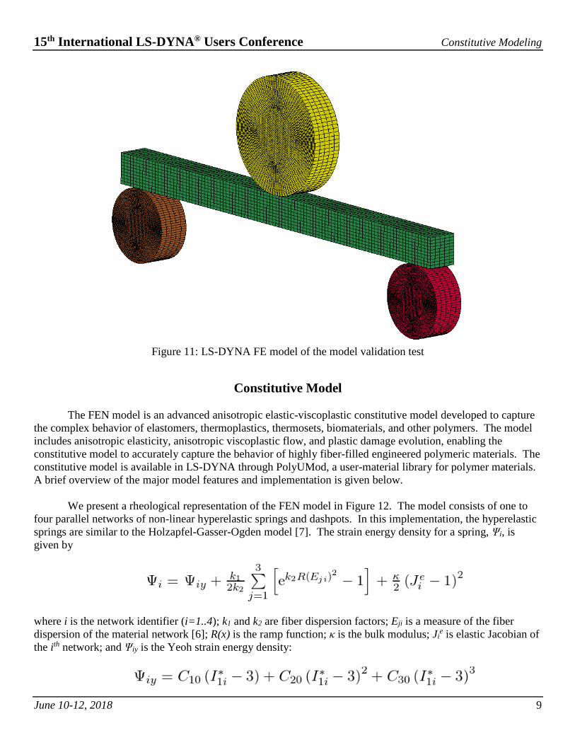
The validation test was modeled in LS-DYNA with the implicit dynamic solver, and the constitutive
model is implemented as a user material for both implicit and explicit solvers [6]. Fixed and loading supports are modeled as rigid bodies, and the test sample is modeled with 5,000 solid elements. Contact was modeled with an ‘automatic’ implementation in LS-DYNA, and the contact was modeled as frictionless. We present the full 3D FE model in Figure 11.

15th International LS-DYNA® Users Conference Constitutive Modeling
June 10-12, 2018 7
Figure 8: Uniaxial compression results for through thickness samples.
Figure 9: Displacement vs. time (left) and force vs. displacement for the three-point bend validation test.

15th International LS-DYNA® Users Conference Constitutive Modeling
June 10-12, 2018 8
Figure 10: DIC images from the three-point bend validation test showing the normal true strain in the sample.
15th International LS-DYNA® Users Conference Constitutive Modeling
June 10-12, 2018 9
Figure 11: LS-DYNA FE model of the model validation test
Constitutive Model
The FEN model is an advanced anisotropic elastic-viscoplastic constitutive model developed to capture
the complex behavior of elastomers, thermoplastics, thermosets, biomaterials, and other polymers. The model includes anisotropic elasticity, anisotropic viscoplastic flow, and plastic damage evolution, enabling the constitutive model to accurately capture the behavior of highly fiber-filled engineered polymeric materials. The constitutive model is available in LS-DYNA through PolyUMod, a user-material library for polymer materials. A brief overview of the major model features and implementation is given below.
We present a rheological representation of the FEN model in Figure 12. The model consists of one to
four parallel networks of non-linear hyperelastic springs and dashpots. In this implementation, the hyperelastic springs are similar to the Holzapfel-Gasser-Ogden model [7]. The strain energy density for a spring, Ψi, is given by
where i is the network identifier (i=1..4); k1 and k2 are fiber dispersion factors; Eji is a measure of the fiber dispersion of the material network [6]; R(x) is the ramp function; κ is the bulk modulus; Ji
e is elastic Jacobian of the ith network; and Ψiy is the Yeoh strain energy density:

15th International LS-DYNA® Users Conference Constitutive Modeling
June 10-12, 2018 10
C10, C20, and C30 are material parameters; and I1i
* is the first deviatoric strain invariant for the ith network. Each network in the model uses the same parameters for fiber dispersion, Yeoh parameters, and bulk modulus. The strain energy density for each network is multiplied by a unique material parameter fiµ, so that the stress contribution from each network is different [6]. The network flow is governed by a power-law flow dashpot given by
where 𝛾𝛾0̇ is defined as 1/s; R(x) is the ramp function; 𝜏𝜏𝚤𝚤� and mi are material parameters for each network; τcut is the normalized flow stress below which no flow will occur; and the effective Hill stress, τi, is
where F, G, H, L, M, and N are material parameters. Further details on the model details and implementation are available in the PolyUMod User’s Manual [6] and Reference [1].
Figure 12: FEN model schematic.
Constitutive Model Calibration and Validation Results
We present the constitutive model calibration results for compression tests at all strain rates in Figure
13. The model captures the material response well. Yield behavior, stress relaxation, and strain-rate dependency is well captured. Figure 14 shows model predictions for the low strain-rate tensile data. The constitutive model matches the experimental data extremely well, with an average error of 8.1%. Overall error for the model is 11% for all experiments performed.
We present results for the material model validation test and simulation in Figure 15. The simulation
results match the experiment well, with an error of 3.5%. The model slightly under-predicts the measured force slightly, and captures the unloading and stress relaxation well. Overall, the error in the constitutive model prediction is very low.

15th International LS-DYNA® Users Conference Constitutive Modeling
June 10-12, 2018 11
Figure 13: Compression calibration results for the FEN model.

15th International LS-DYNA® Users Conference Constitutive Modeling
June 10-12, 2018 12
Figure 14: FEN model calibration predictions for tension tests: 0.001/s (left) and rate dependent predictions
(right).
Figure 15: Constitutive model validation simulation results. Force vs time results (left), and force vs. displacement (right).

15th International LS-DYNA® Users Conference Constitutive Modeling
June 10-12, 2018 13
Conclusions
High performance polymer materials are used extensively under impact conditions, including heavily
fiber filled materials. Testing and calibrating constitutive models for these anisotropic materials is difficult, with few options for anisotropic, rate-dependent constitutive models that can capture the complex material response. We have developed an advanced constitutive model available in PolyUMod for LS-DYNA that accurately captures rate effects and anisotropy typically seen in fiber-filled polymers. We calibrated the constitutive model to experimental data in tension and compression, with applied strain rates from 1x10⁻³ s-1 to 1200 s-1. The calibrated constitutive model matched the test data well. We successfully validated the constitutive model with a validation test to confirm the model would predict multi-axial load cases well. The FEN model is a robust and advanced constitutive model that captures the response of the glass fiber-filled PEI well. The model can also incorporate failure models, though those are not discussed here.
References 1. J. Bergstrom. Mechanics of Solid Polymers. Elsevier, 2015. 2. ASTM International. ASTM D638-14, Standard Test Method for Tensile Properties of Plastics (2014). 3. C.R. Siviour and J.L. Jordan. High Strain Rate Mechanics of Polymers: A Review, Journal of Dynamic Behavior of Materials,
(2016), 2: 15-32. 4. S. Brown, S. Teller, J. Bergstrom, and M. Oliver. Techniques to Measure Impact Properties of Polymers, SPE ANTEC 2018. 5. S. Teller, J. Bergstrom, and G. Freeburn. High Strain Rate Testing and Modeling of Polymers for use in Finite Element
Simulations, SPE ANTEC 2017. 6. PolyUMod User’s Manual. Veryst Engineering. 7. G. A. Holzapfel, T.C. Gasser, and R.W. Ogden. A new constitutive framework for arterial wall mechanics and a comparative study
of material models. J. Elasticity, 61:1-48, 2000. 8. D.K. Francis, W.R. Whittington, W.B. Lawrimore II, P.G. Allison, S.A. Turnage, and J.J. Bhattacharyya. Split Hopkinson Pressure
Bar Graphical Analysis Tool, Experimental Mechanics, 2017 57:179-183.