Embed Size (px)
Citation preview

HIGH-SPEED LINEAR GUIDE

SAIBO is one of world recognized leaders in design and manufacturing
of low friction linear motion components and precision bearings.
SAIBO products are exported to over 30 countries and regions. We
provide not only standard products, but also customized solutions.
SAIBO means “Always reach for higher goals.” SAIBO is committed to
excellence and linear motion innovation while guaranteeing its
customers the best pricing in our industry.
SAIBO actively seeks to work with you on your next design and we
promise the following:
● The right product for your application
● A quality product you can trust
● Engineering assistance that is proven and world renown.
SAIBO is located in WUXI, east China. Wuxi is famous for being one of
the birthplaces of Chinese modern industry. Welcome you visit us.
About US


LGA linear guide systems are mainly made of lightweight material of aluminum alloy. Four rollers inside the carriage run on railway's hardened shafts. Stable rolling movement are particularly suitable for use in material handling system and automatic production lines. Below picture shows its construction.
LGA linear guide
1.High speed, Low friction and Low noise2.Preload is adjustable 3.Sealed and Lubricated
Construction
Railway Anodized aluminum alloy body with two Chrome-plated steel shafts
Carriage Anodized aluminum alloy plate 4 pieces double row balls bearings(Rollers)2 pieces concentric bolts and 2 pieces eccentric bolts2 pieces plastic lubrication cover with oil soaked felt wipers
Feature
1

2
SB-LGA20
SB-LGA25
SB-LGA30
H
30
32.5
38.5
F
20
28
34.2
A
63
80
100
B
92
105
120
C
53
60
85
E
40
40
50
H1
26
28
33
H H1
A
SAIBO
DF
I
Carriage DimensionsAssembly DimensionsType

3
B
C
E
S P
G x depth
G1
L
4-M x depth
G1
5.5
5.5
6.5
M x depth
M6x8
M6x8
M8x10
I
19.5
20
24
P
60
50
50
Lmax*
1020
3000
4000
S
30
25
25
G xdepth
9x5.5
12.5x5.5
14.5x6.5
D
6
8
10
Railway Dimensions
4
Oil soaked felt swiperLubrication hole
Setting clearance - free None clearance is necessary for system's rigidity and stability. LGA series use 2 concentric bolts on one side in the direction of railway and 2 eccentric bolts on the other side. These two eccentric bolts are used for setting clearance-free.
1. Tighten concentric bolts.
2. Tighten the eccentric bolts to near the critical point, but not reach the critical point. (This is to rotate the eccentric bolts).
3. Rotate the eccentric bolts with straight screwdriver at the end of the stud to adjust the clearance. Adjust the clearance to zero.
4. Slide the carriage by hand and adjust to the extent where there causes a slight slipping resistance.
5. Keep eccentric bolt's position and tighten the nut.
Setting Pre-load It is same as Setting clearance-free. First adjust clearance to zero, continue rotating eccentric bolts will get pre-load. Appropriate pre-load should be decided according to the application. Over pre-load will decrease system's life. Please be careful.
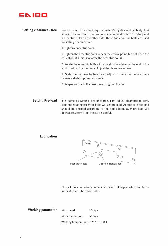
Lubrication
SAIBO
Plastic lubrication cover contains oil soaked felt wipers which can be re-lubricated via lubrication holes.
Working parameter Max speed: 10m/s
2Max acceleration: 50m/s
Working temperature: 2 ~ +80- 0°C °C

Accuracy
Tolerance H :±0.20mm
Note: Higher accuracies are available upon request.
5
H
SAIBO

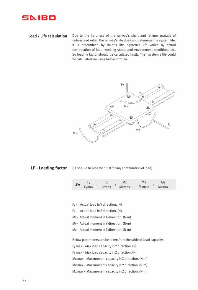
Due to the hardness of the railway's shaft and fatigue analysis of railway and roller, the railway's life does not determine the system life. It is determined by roller's life. System's life varies by actual combination of load, working status and environment conditions etc. So loading factor should be calculated firstly. Then system's life could be calculated via using below formula.
LF - Loading factor (LF should be less than 1.0 for any combination of load)
Fy - Actual load in Y direction. (N)
Fz - Actual load in Z direction. (N)
.Mx - Actual moment in X direction. (N m)
.My - Actual moment in Y direction. (N m)
.Mz - Actual moment in Z direction. (N m)
Below parameters can be taken from the table of Load capacity.
Fy max - Max load capacity in Y direction. (N)
Fz max - Max load capacity in Z direction. (N)
.Mx max - Max moment capacity in X direction. (N m)
.My max - Max moment capacity in Y direction. (N m)
.Mz max - Max moment capacity in Z direction. (N m)
Load / life calculation
Mz
Fy
Mx
Fz
My
LF = + + + +Fy
FymaxFz
FzmaxMx
Mxmax
MyMymax
MzMzmax
6

Life calculation SAIBO designed LGA series load capacity according to basic life of 100km for each type. System's life in km could be calculated via below formula.
Life(km) =100
3( 0.03+0.97LF*f )
f - Reduction coefficient of the application and environment.
Load capacity
Mymax Mzmax
Max Load capacity(N) .Max moment capacity(N m)
Fymax Fzmax MxmaxRailway type
330
520
1200
600
1200
4000
1.8
7.6
26
7
26
78
5.8
15
45
SB-LGA20
SB-LGA25
SB-LGA30
None vibration or shock, Low speed (<1m/s),
Low frequency shift direction, clean environment.
Light vibration or shock, medium speed (1-2.5m/s)
medium frequency shift direction, some dirtiness
Heavy vibration or shock, high speed (>2.5m/s)
high frequency shift direction, heavy dirty
1-1.5
1.5-2
2-3.5
7

Calculation example Here select SB-LGA25 as calculation example. This system is loaded as below picture. Working condition is clean and there is no vibration or shock.
The load factor LF is
calculated use formula LF =Fy
FymaxFz
Fzmax
Mx
Mxmax
My
MymaxMz
Mzmax + + + +
Take parameters Fy max, Fz max, Mx max, My max, Mz max from table and then fill in the formula
LF =49
52010
12000.987.60
0Mymax
0Mzmax
+ + + + = 0.2314
According to the description of working condition, take f=1.1
Life(km) =100
3(0.03+0.97LF*f )
=100
3(0.03+0.97*0.2314*1.1)
= 4716km
Fy = 5 kg x 9.8 (gravity) = 49 N
Fz = 10 N
.Mx = 49 x 0.02 = 0.98 N m
My = 0
Mz = 0
0.02m
5Kg
10N
SAIBO LGA25
8

LGB linear guide systems are designed for compact space application. The carriages are in narrow structures. Railway, narrow carriage and lubrication cover are its basic construction.
LGB linear guide
1.High speed, Low friction and Low noise2.Preload is adjustable3.Narrow body for compact application4.Optional Lubrication covers
Construction
Railway Anodized aluminum alloy body with two Chrome-plated steel shafts
Carriage Anodized aluminum alloy plate 3 pieces double row balls bearings(Rollers)Eccentric bolt used for adjust the clearane/preloadOptional lubrication covers with oil soaked felt wipers
Feature
9

* This size does not include plastic cover
length must add 5.0mm to size B.
's thickness. All size plastic cover's thickness is 2.5mm. So covered carriages'
10
A
H1
H
F
D
I
SB-LGB15
SB-LGB20
SB-LGB25
H
28.8
35.5
43
F
32
47
65
E
70
50
130
C
20
38
47
B*
88
108
150
A
28
47
64
E 1
6 5
TypeAssembly Dimensions Carriage Dimensions

11
L
B
E
E1
CM
G x depth
G1
S P
D
6
8
10
G1
4.5
5.5
6.5
H1
10.9
11.5
14.7
S
30
30
30
Lmax
3000
3000
3000
I
17
21.75
26.5
M
4xM5
4xM6
6xM8
P
60
60
60
G x depth
7.5x2.5
9.5x5
11x4
Railway Dimensions

Max speed: 10m/s2Max acceleration: 50m/s
Working temperature: ~ +80-20°C °C
Setting clearance - free None clearance is necessary for system's rigidity and stability. LGB series carriage has two concentric bolts on both sides and one eccentric bolt in the center along the railway. This eccentric bolt is used for setting clearance-free.
1. Tighten concentric bolts.
2. Tighten the eccentric bolt to near the critical point, but not reach the critical point. (This is for rotate the eccentric bolts).
3. Rotate the eccentric bolts with internal hexagonal wrench in the end of the eccentric bolt to adjust the clearance. Adjust the clearance to zero.
4. Slide the carriage by hand and adjust to the extent where there causes a slight slipping resistance.
5. Keep eccentric bolt's position and tighten the nut.
Setting Pre-load It is same as Setting clearance-free. First adjust clearance to zero, continue rotating eccentric bolt will get pre-load. Appropriate pre-load should be decided according to application. Over pre-load will decrease system's life. Please be careful.
Lubrication
Oil soaked felt wiper
Lubrication hole
SAIBO
Plastic lubrication cover contains oil soaked felt wipers which can be re-lubricated via lubrication hole. This lubrication cover is optional, not included in standard carriage.
Working parameter
12

Accuracy
SAIBO
H
13
Tolerance H :±0.20mm
Note: Higher accuracies are available upon request.

Load / life calculation
Fy
Fz
Mx
MZ
My
LF - Loading factor (LF should be less than 1.0 for any combination of load)
LF = + + + +Fy
FymaxFz
FzmaxMx
Mxmax
MyMymax
MzMzmax
14
Fy - Actual load in Y direction. (N)
Fz - Actual load in Z direction. (N)
.Mx - Actual moment in X direction. (N m)
.My - Actual moment in Y direction. (N m)
.Mz - Actual moment in Z direction. (N m)
Below parameters can be taken from the table of Load capacity.
Fy max - Max load capacity in Y direction. (N)
Fz max - Max load capacity in Z direction. (N)
.Mx max - Max moment capacity in X direction. (N m)
.My max - Max moment capacity in Y direction. (N m)
.Mz max - Max moment capacity in Z direction. (N m)
Due to the hardness of the railway's shaft and fatigue analysis of railway and roller, the railway's life does not determine the system life. It is determined by roller's life. System's life varies by actual combination of load, working status and environment conditions etc. So loading factor should be calculated firstly. Then system's life could be calculated via using below formula.

Life calculation SAIBO designed LGB series load capacity according to basic life of 100km for each type. So after customers designed system's actual load, system's life could be calculated via below formula.
Life(km) =100
3( 0.03+0.97LF*f )
f - Reduction coefficient of the application and environment.
Load capacity
Mymax Mzmax
Max Load capacity(N) Max moment capacity(N.m)
Fymax Fzmax MxmaxRailway type
330
520
1200
1000
1200
4000
1.8
6.6
19
12
45
120
5.5
15
50
SB-LGB15
SB-LGB20
SB-LGB25
None vibration or shock, Low speed (<1m/s),
Low frequency shift direction, clean environment.
Light vibration or shock, medium speed (1-2.5m/s)
medium frequency shift direction, some dirtiness
Heavy vibration or shock, high speed (>2.5m/s)
high frequency shift direction, heavy dirty
1-1.5
1.5-2
2-3.5
15

Calculation example Here select SB-LGB20 as calculation example. This system loaded as blow picture. Working condition is clean and there is no vibration or shock.
The load factor LF is
calculated use formulaLF =
Fy
FymaxFz
Fzmax
Mx
Mxmax
My
MymaxMz
Mzmax + + + +
Take parameters Fy max, Fz max, Mx max, My max, Mz max from
table and then fill in the formula
LF =58.8520
101200
0.406.60
0Mymax
0Mzmax
+ + + + = 0.182
Life(km) =100
3(0.03+0.97LF*f )
=100
3(0.03+0.97*0.182*1.1)
= 8849km
Fy = 6 kg x 9.8 (gravity) = 58.8 N
Fz = 10 N
.Mx = 10 x 0.04 = 0.40 N m
My = 0
Mz = 0
SAIBOLGB20
6kg
10N
0.0
4m
According to the description of working condition of light shock,
take f=1.1
16
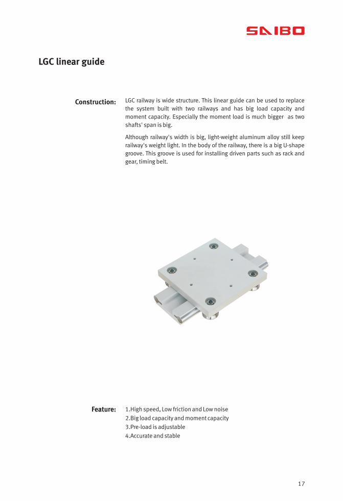
Construction:
Feature: 1.High speed, Low friction and Low noise
2.Big load capacity and moment capacity
3.Pre-load is adjustable
4.Accurate and stable
LGC railway is wide structure. This linear guide can be used to replace the system built with two railways and has big load capacity and moment capacity. Especially the moment load is much bigger as two shafts' span is big.
Although railway's width is big, light-weight aluminum alloy still keep railway's weight light. In the body of the railway, there is a big U-shape groove. This groove is used for installing driven parts such as rack and gear, timing belt.
LGC linear guide
17

Advantage compare with two railways
Compare to the structure by using two railways, LGC linear guide's advantages are:
1.Easy to install the railway.
When install two railways, two railways' parallel must be controlled strictly. And it is a trouble. LGC linear guide does not need this job.
2.Dia20 shaft make system's rigidity and strength stronger.
This can make carriage's load capacity much bigger. And also the system's stability will improve a lot.
3.Increase system's life.
According to life calculation formula, Life Factor (LF) is the main determinant of the life. At same load capacity, LGC linear guide's LF will be much smaller than by using two railways. This will increase system's life.
System built with two small railways.
Same size carriage, SB-LGC carriage's load capacity is much bigger than
the system built with two railways.
18

Setting clearance - free
None clearance is necessary for system's rigidity and stability. LGC series use 2 concentric bolts one side in the direction of railway and 2 eccentric bolts on the other side. These two eccentric bolts are used for setting clearance-free.
1. Tighten concentric bolts.
2. Tighten the eccentric bolts to near the critical point, but not reach the critical point. (This is to rotate the eccentric bolts).
3. Rotate the eccentric bolts with wrench at the end of the stud to adjust the clearance. Adjust the clearance to zero.
4. Slide the carriage by hand and adjust to the extent where there causes a slight slipping resistance.
5. Keep eccentric bolt's position and tighten the nut.
Setting Pre-load It is same as Setting clearance-free. First adjust clearance to zero, continue rotating eccentric bolts will get pre-load. Appropriate pre-load should be decided according to application. Over pre-load will decrease system's life. Please be careful.
Working parameter Max speed: 10m/s
2Max acceleration: 50m/s
Working temperature: ~ +80-20°C °C
Accuracy
H
19
Tolerance H :±0.20mm
Note: Higher accuracies are available upon request.

Dimension
20
H H1
DJ
F
KI
A
SB-LGC100
SB-LGC130
H
51
51
A
200
230
B
200
230
C
140
180
E
140
160
M
4-M8
4-M8
H1
48
48
F
99
130
Carriage DimensionsAssembly DimensionsType

B
E
C
N
L
M
SPG x depth
G1
Lmax*
6000
6000
P
300
300
S
30
30
N
62
90
K
18
18
J
40
65
I
30
30
G1
9
9
G x depth
14x5.5
14x5.5
D
20
20
21
Railway Dimensions
Load / Life calculation
Fy
My
Fz
MzMx
LF - Loading factor (LF should be less than 1.0 for any combination of load)
LF = + + + +Fy
FymaxFz
FzmaxMx
Mxmax
MyMymax
MzMzmax
22
Fy - Actual load in Y direction. (N)
Fz - Actual load in Z direction. (N)
.Mx - Actual moment in X direction. (N m)
.My - Actual moment in Y direction. (N m)
.Mz - Actual moment in Z direction. (N m)
Below parameters can be taken from the table of Load capacity.
Fy max - Max load capacity in Y direction. (N)
Fz max - Max load capacity in Z direction. (N)
.Mx max - Max moment capacity in X direction. (N m)
.My max - Max moment capacity in Y direction. (N m)
.Mz max - Max moment capacity in Z direction. (N m)
Due to the hardness of the railway's shaft and fatigue analysis of railway and roller, the railway's life does not determine the system life. It is determined by roller's life. System's life varies by actual combination of load, working status and environment conditions etc. So loading factor should be calculated firstly. Then system's life could be calculated via using below formula.

Life calculation SAIBO designed LGC linear guide load capacity according to basic life of 100km. System's life in km could be calculated using below formula.
Life(km) =100
3( 0.03+0.97LF*f )
f - Reduction coefficient of the application and environment.
Load capacity
Mymax Mzmax
Max Load capacity(N) .Max moment capacity(N m)
Fymax Fzmax MxmaxRailway type
None vibration or shock, Low speed (<1m/s),
Low frequency shift direction, clean environment.
Light vibration or shock, medium speed (1-2.5m/s)
medium frequency shift direction, some dirtiness
Heavy vibration or shock, high speed (>2.5m/s)
high frequency shift direction, heavy dirty
1-1.5
1.5-2
2-3.5
23
SB-LGC100
SB-LGC130
190
240
6000
6000
6000
6000
210
240
210
240
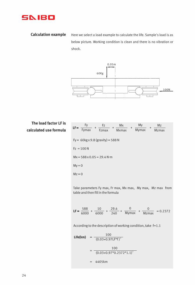
Calculation example Here we select a load example to calculate the life. Sample's load is as
below picture. Working condition is clean and there is no vibration or
shock.
The load factor LF is
calculated use formulaLF =
Fy
FymaxFz
Fzmax
Mx
Mxmax
My
MymaxMz
Mzmax + + + +
Take parameters Fy max, Fr max, Mx max, My max, Mz max from table and then fill in the formula
LF =588
600010
600029.4240
0Mymax
0Mzmax
+ + + + = 0.2372
Life(km) =100
3(0.03+0.97LF*f )
=100
3(0.03+0.97*0.2372*1.1)
= 4405km
Fy = 60kg x 9.8 (gravity) = 588 N
Fz = 100 N
.Mx = 588 x 0.05 = 29.4 N m
My = 0
Mz = 0
0.05m
60Kg
100N
According to the description of working condition, take f=1.1
24


All rights reserved.
Due to constant development of the products,we reserve the right of modifications without notifications.

WUXI SAIBO INDUSTRY CO LIMITED6-701 XIHU EAST ROAD, WUXI 214011, CHINATel: +86-510-8230 0095Fax: +86-510-8230 0096
www. [email protected] SB2018 No.1 EN