Embed Size (px)
Citation preview
1 WE PARTNER WITH OUR CUSTOMERS TO IMPROVE, SAVE AND PROTECT PEOPLE’S LIVES
High SEE Tolerance in a Radiation Hardened CMOS Image Sensor
Designed for the Meteosat Third Generation FCI-VisDA Instrument
Simpson, R., Swift, N., Pratlong, J., Pike, A., Jerram, P. e2v, 106 Waterhouse Lane, Chelmsford, Essex, CM2 9GL
CMOS Image Sensors for High Performance Applications
18th and 19th Nov 2015

2
Introduction
• The CIS111 sensor has been designed by e2v for the Metosat Third Generation (MTG) Flexible Combined Imager instrument.
• MTG programme is a cooperation between EUMETSAT and ESA to provide meteorological data from geostationary orbit into the 2030s.
• e2v contracted by satellite prime Thales Alenia Space – France (TAS-F) to deliver a space qualified custom CMOS sensor.
• This presentation focuses on ground-based radiation testing performed to ensure suitability of the design for this application.

3
Contents
1. Sensor Description
i. Overview
ii. Shift Registers
2. Single Event Effects
3. Heavy Ion Testing
i. Test Facility
ii. Methodology
4. Test Results
i. Single Event Latchup
ii. Single Event Upset
5. Data Analysis
i. Calculating Mission SEE Rate
ii. Worst Case Analysis
6. Conclusions
7. Acknowledgements
4
Device Description
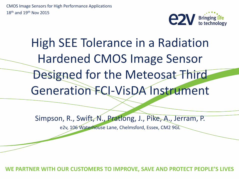
Overview
• 0.18 µm Imaging CMOS process
• 12 µm epi thickness
• 4T architecture
• 5 channel multi-spectral imager
• Integrated sequencer generates pixel timing and readout control signals
• SPI for column selection
• Analogue outputs (separate outputs for video signal and dark reference)
5
Device Description
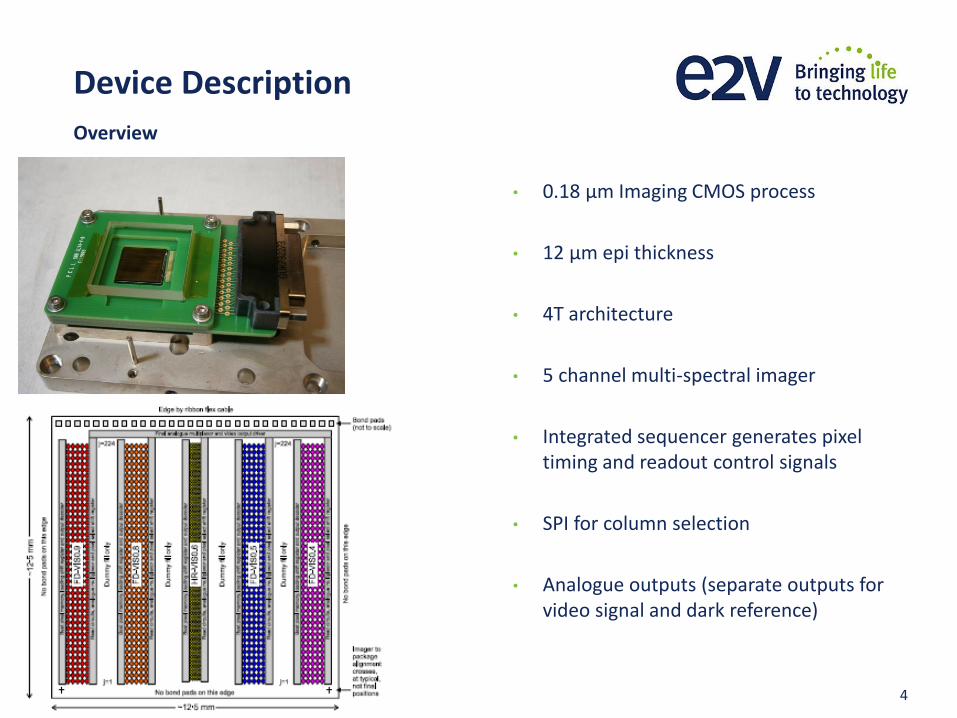
Shift Registers
• Shift register architecture used on CMOS digital circuits for simplicity:
• Integral sequencer
• Readout Select
• Serial Programmable Interface
• Triple mode redundancy used to increase SEU hardness.
• Two types of shift register used:
• Rad-hard
• Implemented for all digital control functions except for the SPI
• TMR refreshed at 4 MHz rate
• Low power
• Less radiation hard
• Implemented for the SPI
• TMR refreshed at 2.6 kHz rate

6
Single Event Effects
Types of SEE
• Non-destructive
• Single event upset (SEU) – change of logic state in memory element.
• Single event transient (SET) – transients in circuit that lead to erroneous data being captured.
• Single event functional interrupt (SEFI) – temporary loss of device functionality (for imager of this simplicity, this is caused by bus contention).
• Destructive
• Single event latchup (SEL) – parasitic thyristor causes circuit lockup or catastrophic failure.
• MTG has design features to mitigate against these SEE types:
• Triple mode redundancy (SEU)
• Big transistors with large drive and capacitance (SET)
• Big global clock buffers with high output capacitance (SET)
• Layout considerations and guard rings around all wells (SEL)

7
Heavy Ion Testing
• Test facility at Universite Catholique Louvain (UCL), Belgium.
• Cyclotron has two heavy ion cocktails:
• Low energy – LET range 3 to 67 MeV cm2 mg-1
• High energy – LET range 1 to 31 MeV cm2 mg-1
• Heritage
• Sentinel 2 A/B
• CIS108 Radiation Testchip (e2v Private Venture)
• MTG FCI VisDA
• Future
• Sentinel 2 C/D
• CIS115 (BI CMOS based on CIS107 OCI)
• CIS113 (used for TAOS II) ???
• Radiation Testchip 2 (e2v Private Venture)
Test Facility
8
Heavy Ion Testing
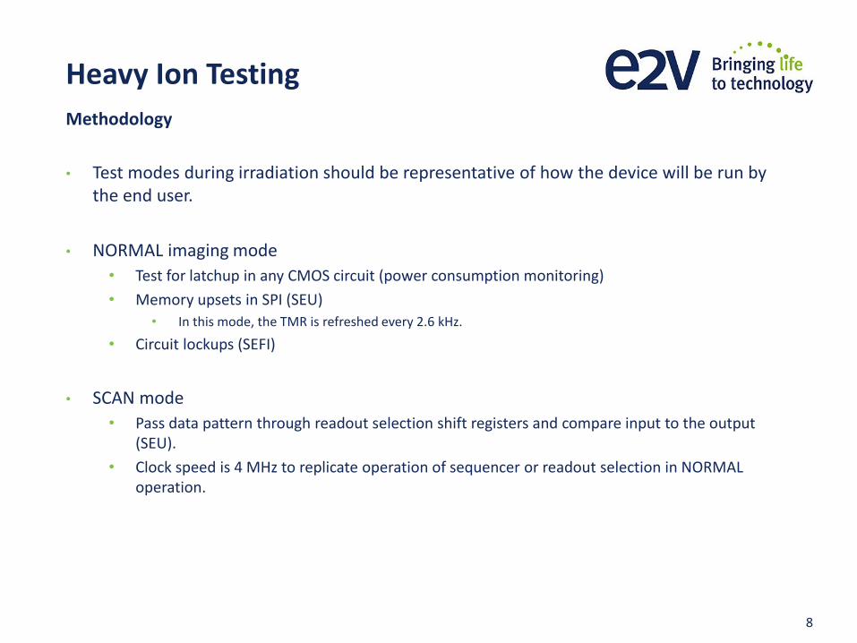
• Test modes during irradiation should be representative of how the device will be run by the end user.
• NORMAL imaging mode
• Test for latchup in any CMOS circuit (power consumption monitoring)
• Memory upsets in SPI (SEU)
• In this mode, the TMR is refreshed every 2.6 kHz.
• Circuit lockups (SEFI)
• SCAN mode
• Pass data pattern through readout selection shift registers and compare input to the output (SEU).
• Clock speed is 4 MHz to replicate operation of sequencer or readout selection in NORMAL operation.
Methodology

9
Test Results
• No SEL observed at a LET of up to 67.7 MeV cm2 mg-1.
• Low energy cocktail – tested up to 67.7 MeV cm2 mg-1 (Xenon ion).
• Tilt angle 0° due to low range of xenon ion in silicon.
• Total Fluence of 2.56 x 107 cm-2 .
• High energy cocktail – tested up to an effective LET of 65.2 MeV cm2 mg-1 (Krypton ion at 60° tilt angle, LET at normal incidence 32.6 MeV cm2 mg-1).
• Total fluence of 1.51 x 107 cm-2.
• No high current states observed due to SEFI.
Single Event Latchup
10
Test Results
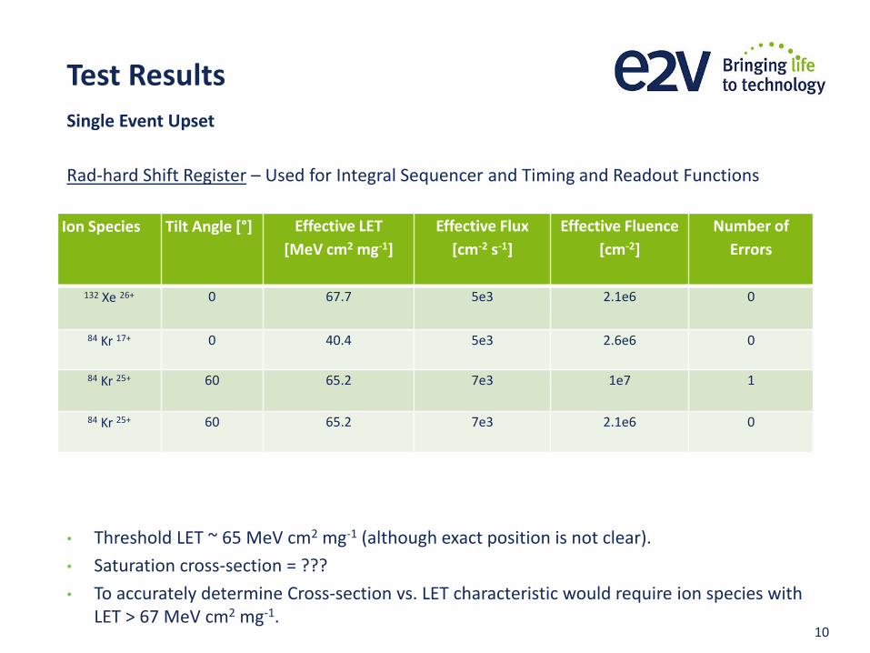
Rad-hard Shift Register – Used for Integral Sequencer and Timing and Readout Functions
• Threshold LET ~ 65 MeV cm2 mg-1 (although exact position is not clear).
• Saturation cross-section = ???
• To accurately determine Cross-section vs. LET characteristic would require ion species with LET > 67 MeV cm2 mg-1.
Single Event Upset
Ion Species Tilt Angle [°]
Effective LET
[MeV cm2 mg-1]
Effective Flux
[cm-2 s-1]
Effective Fluence
[cm-2]
Number of
Errors
132 Xe 26+ 0 67.7 5e3 2.1e6 0
84 Kr 17+ 0 40.4 5e3 2.6e6 0
84 Kr 25+ 60 65.2 7e3 1e7 1
84 Kr 25+ 60 65.2 7e3 2.1e6 0
11
Test Results
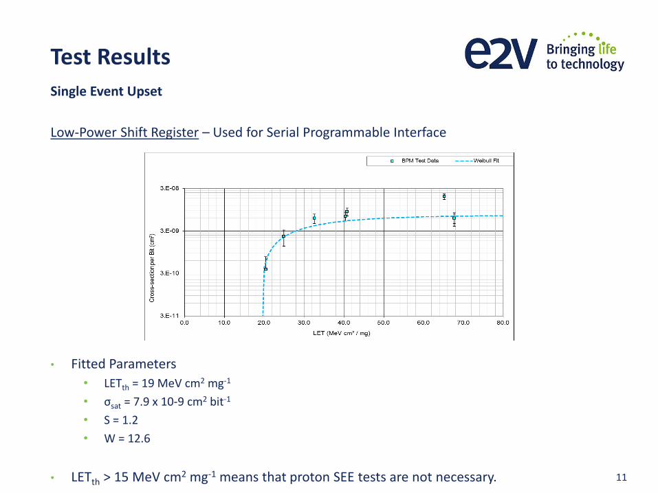
Low-Power Shift Register – Used for Serial Programmable Interface
• Fitted Parameters
• LETth = 19 MeV cm2 mg-1
• σsat = 7.9 x 10⁻⁹ cm2 bit-1
• S = 1.2
• W = 12.6
• LETth > 15 MeV cm2 mg-1 means that proton SEE tests are not necessary.
Single Event Upset
12
Data Analysis
• Cross-section vs. LET characteristic is used to estimate mission SEE rate.
• Most common algorithm used is the rectangular parallelepiped (RPP) model.
• But the RPP model could not be used in this instance:
• For very rad-hard circuits (threshold LET > 67 MeV cm2 mg-1) it is impossible to determine the saturation cross-section.
• For shift register with triple mode redundancy, the cross-section is a function of radiation flux.
• Radiation flux during testing >> radiation flux in space
• Therefore the measured cross-section < mission SEE cross-section, giving very inaccurate results
• Instead e2v performed a worst case analysis to estimate in-flight SEE rate.
• To accurately calculate the mission SEE rate of triple mode redundant features, requires a specialised test method and test structures.
• Requires measurement of Cross-section vs. LET characteristic on single shift register without TMR.
Calculating Mission SEE Rate

13
Data Analysis
• A worst case analysis was used to estimate the in-orbit SEE rates for latchup and upsets.
• As there is not enough information for a full cross-section vs. LET curve, instead a step function is used with the step at LETth
• Predicted SEE Rate:
• Single Event Latchup
• Mission Rate < 2 x 10⁻⁶ day-1
• Reliability over 8.5 year mission lifetime > 99.2 %
• Single Event Upset in rad-hard shift register (sequencer, timing and readout control)
• Mission Rate < 4 x 10-12 day-1
• Availability over 8.5 year mission lifetime > 99.9999 %
• Single Event Upset in low-power shift register (serial programmable interface)
• Mission Rate < 1 x 10⁻⁸ day-1
• Availability over 8.5 year mission lifetime > 99.996 %
Worst Case Analysis

14
Conclusions
• Sensor for Meteosat Third Generation FCI-VisDA shows high immunity to SEE.
• Sensor is invulnerable to proton induced SEE.
• Calculating an in-orbit SEE rate is complicated by the triple mode redundancy of shift registers.
• Only a worst case in-orbit SEE rate can be obtained.
• Despite the worst case analysis, the results are still extremely positive.
15
Acknowledgements
A special thanks to:
e2v – Jeremy Stent, Denis Bourke, Amr Ibrihim for your knowledge and support.
TAS-F – ???
ESA – Mark Wilson
Astrium Elancourt (now Airbus Defence and Space) – Christian Binios for technical and hardware support.

16
WE PARTNER WITH OUR CUSTOMERS TO IMPROVE, SAVE AND PROTECT PEOPLE’S LIVES
OUR INNOVATIONS LEAD DEVELOPMENTS IN COMMUNICATIONS, AUTOMATION, DISCOVERY, HEALTHCARE AND THE ENVIRONMENT