Embed Size (px)
Citation preview
HAL Id: jpa-00253994https://hal.archives-ouvertes.fr/jpa-00253994
Submitted on 1 Jan 1995
HAL is a multi-disciplinary open accessarchive for the deposit and dissemination of sci-entific research documents, whether they are pub-lished or not. The documents may come fromteaching and research institutions in France orabroad, or from public or private research centers.
L’archive ouverte pluridisciplinaire HAL, estdestinée au dépôt et à la diffusion de documentsscientifiques de niveau recherche, publiés ou non,émanant des établissements d’enseignement et derecherche français ou étrangers, des laboratoirespublics ou privés.
High Purity in Steels as a Criterion for MaterialsDevelopment
H. Jacobi, F. Rakoski
To cite this version:H. Jacobi, F. Rakoski. High Purity in Steels as a Criterion for Materials Development. Journal dePhysique IV Colloque, 1995, 05 (C7), pp.C7-3-C7-22. <10.1051/jp4:1995701>. <jpa-00253994>

JOURNAL DE PHYSIQUE IV Colloque C7, supplkment au Journal de Physique III, Volume 5, novembre 1995
High Purity in Steels as a Criterion for Materials Development
H. Jacobi and F. Rakoski*
C/O Mannesmannrohren Werke AG, Mannesmann Forschungsinstitut, Ehinger Strasse 200, 47259 Duisburg (Huckingen), Germany * C/O Krupp Edelstahlprofile GmbH, Obere Kaiserstrasse, 57078 Siegen, Germany
ABSTRACT. This summarizing report discusses the materials and application prospects for higher purity in steels, which will make possible further advances in materials behaviour and workability. Improvements in purity and homogeneity permit in particular more rational production of thin foils and wire, one-piece shaping of complicated bodywork components and the drawing, wall-ironing and flanging of two-piece beverage cans. Welded designs in plant and mechanical engineering can be fabricated with less effort and less weight. Difficult component geometries and shaping processes can be more easily mastered. Steels with optimized fracture toughness can be exposed to more extreme loads at even lower temperatures: applications worthy of mention include offshore engineering and large-diameter linepipes for use in arctic regions and at great underwater depths. Liquefied-gas transport vessels can be made more resistant to brittle rupture. The bending fatigue strength and service-life of valve-spring and rolling- bearing steels can be significantly increased. High-purity surfaces on piston rods and cylinders guarantee reliability in hydraulic systems, and high-purity calendering rolls permit defect-free embossing of paper surfaces.
1. INTRODUCTION
Great progress has been achieved in the refining of steel heats in recent years [I]. Material conversion has been accelerated by means of intensive mixing. Sources of disruption in the refining and casting processes have been brought under control. Metallurgical processing now occurs under controlled and repeatable conditions. The user industries can now rely on dependable and consistent materials properties in steels [2,3]. New and attractive properties are being opened up and the range of existing ones rationally combined. Ultra-pure steels are now widely produced for special applications [4,5]. The present summarizing report discusses the status and development of the materials technology for high-purity steels.
2. PURITY CRITERIA
Ultra-pure (99.999 %) iron is scarcely used commercially and the amounts produced are less significant. Instead, this transitional metal attains its attractive mechanical and technological properties via the routes of alloying, heat treatment and deformation [6]. The potentials of these routes are virtually unlimited.
The term "purity" is used in the context of steels to signify a large range of things. Figure 1 defines six different purity criteria which may need to be taken into account either individually or in various combinations, depending on specific requirements. The workability and in-service behaviour of steels can be seriously impaired by certain trace and tramp elements and by undesirable precipitations and non-metallic inclusions. Critical-element contents can, if necessary, be decreased to extremely low levels. The lower limits of such concentrations are: C = 10 ppm, N = 15 ppm, H = 1.5 ppm, P = 20-40 ppm, S = 5 ppm and Ot = 5 ppm. Inclusions can either be prevented from occurring at all or modified by means of "shape control" in such a way that they are rendered harmless for the intended application.
Interstitial and substitutional purity, and grain-boundary purity, in particular, depend essentially on the melting process used. BOF steel is based primarily on "clean" ore, EAF steel, on the other hand, on contaminated and/or alloyed scrap. The scrap imports the following trace elements into the steel: Cu, Ni,
Article published online by EDP Sciences and available at http://dx.doi.org/10.1051/jp4:1995701

C7-4 JOURNAL DE PHYSIQUE IV
Sn, Sb, As, Cr, Mo, Zn, Pb, Cd, Bi, etc. These elements accumulate within the steel production cycle. Some of them segregate on the outer free surface and at the grain boundaries and interfaces.
Grain-boundary segregations of the tramp elements mentioned above, including P and S, cause embrittlement of the grain boundaries. For this reason, these residual elements frequently need to be stably fixed or displaced from the grain boundaries by the solute elements C, N or B from the bulk. Figure 2 illustrates the displacement of Sn by C in ferrous alloys [7]. P is displaced by C in the same way. High interstitial purity, as is found in mild formable ULC/IF steels and in the presence of powerful carbide-forming agents, therefore weakens the grain boundaries.
microscopic macroscopic
Grain boundaly substitutional
Figure 1: Assessment criteria for the purity Figure 2: Grain boundary segregation of Sn and C in ferrous and homogeneity of steels. alloys. Expulsion of Sn as a result of increasing C contents 171.
The metallurgy and materials technology of high-purity steels are constrained by the following background conditions: existing production lines, raw-materials availability, energy input, environmental impact and recyclability. Suitable scrap preparation and sorting, and appropriate selection of alloying elements, slagging agents and refractory materials, are vital preconditions. In many instances, high-purity steels are integrated into tonnage steel production and need this underlying infrastructural support for economic reasons. The exclusion of high-purity steels from future shortenings of process-routes and leaner production lines is therefore inconceivable.
The criteria of substitutional and grain-boundary purity are of great significance in the context of EAF steels.
BOF steelplants are less affected by this. They are, instead, obliged to devote much more attention to interstitial purity and, of course, to oxide cleanness, which plays a key role in terms of manufacturing reliability and yield in practically all products which use high-purity steels. This is, therefore, the focus of the present report
2.1 Microscopic Cleanness
Microscopic cleanness addresses the problem of small inclusions which occur with a high frequency. Average particle diameter in as-cast condition is, for instance, around 2-5 pm. This category includes MnS inclusions and Mn silicates, which are precipitated inter-dendritically during solidification, and also A1203 and TIN, where these are not present in the form of clusters. Microscopic cleanness can be unequivocally characterized, even for scientific purposes, in metallographic terms via the relationship
between size and frequency [8J. Even individual microsections with a surface area of 20 mm x 20 mm provide representative results.
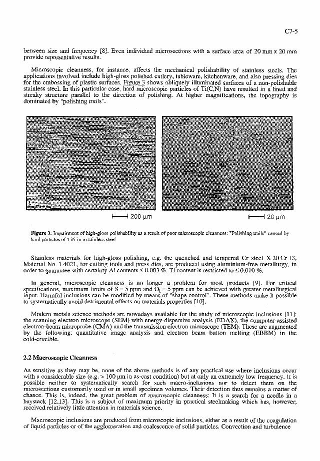
Microscopic cleanness, for instance, affects the mechanical polishability of stainless steels. The applications involved include high-gloss polished cutlery, tableware, kitchenware, and also pressing dies for the embossing of plastic surfaces. Figure 3 shows obliquely illuminated surfaces of a non-polishable stainless steel. In this particular case, hard microscopic particles of Ti(C,N) have resulted in a lined and streaky structure parallel to the direction of polishing. At higher magnifications, the topography is dominated by "polishing trails".
Figure 3: Impairment of high-gloss polishability as a result of poor microscopic cleanness: "Polishing trails" caused by hard particles of TiN in a stainless steel
Stainless materials for high-gloss polishing, e.g. the quenched and tempered Cr steel X 20 Cr 13, Material No. 1.4021, for cutting tools and press dies, are produced using aluminium-free metallurgy, in order to guarantee with certainty A1 contents 1 0.003 %. Ti content is restricted to 10.010 %.
In general, microscopic cleanness is no longer a problem for most products [9]. For critical specifications, maximum limits of S = 5 ppm and Ot = 5 ppm can be achieved with greater metallurgical input. Harmful inclusions can be modified by means of "shape controIV. These methods make it possible to systematically avoid detrimental effects on materials properties [lo].
Modern metals science methods are nowadays available for the study of microscopic inclusions [ l l ] : the scanning electron microscope (SEM) with energy-dispersive analysis (EDAX), the computer-assisted electron-beam microprobe (CMA) and the transmission electron microscope (TEM). These are augmented by the following: quantitative image analysis and electron beam button melting (EBBM) in the cold-crucible.
2.2 Macroscopic Cleanness
As sensitive as they may be, none of the above methods is of any practical use where inclusions occur with a considerable size (e.g. > 100 ym in as-cast condition) but at only an extremely low frequency. It is possible neither to systematically search for such macro-inclusions nor to detect them on the microsections customarily used or in small specimen volumes. Their detection thus remains a matter of chance. This is, indeed, the great problem of macroscopic cleanness: It is a search for a needle in a haystack [12,13]. This is a subject of maximum priority in practical steelmaking which has, however, received relatively little attention in materials science.
Macroscopic inclusions are produced from microscopic inclusions, either as a result of the coagulation of liquid particles or of the agglomeration and coalescence of solid particles. Convection and turbulence

C7-6 JOURNAL DE PHYSIQUE IV
Figure 4: Agglomeration of TiN particles during Figure 5: Macroscopic coral-shaped cluster consisting casting; disintegration of cluster at rolling. (a) as-cast, of coalesced microscopic A1201 particles. (b) reduction ratio 33 % (c) 83 %, (d) 96.7 % 1141.
during casting promote these processes. Figure 4 shows a cluster of cuboid TiN particles which was disintegrated during deformation [14]. The fragments have been dispersed along the direction of rolling. Solid A1203 particles can also accumulate in a coral-shaped configuration in the same way. The SEM image in Figure 5 shows that the individual particles are only 2-5 pm in size. The growth of such "corals" is collision-controlled and occurs primarily on the walls of nozzles [15]. The clusters then detach from the walls and are embedded in the cast strand.
2 loo - g 0
0 1 2 3 4 5 6 7 8 9 1 0 1 1 1 2 Head Distance (m) Tail
100
c 80 - 0 .- -
60 - 2 $ 40- .-
o E - v, & 20
a m t
(a) Single microsection 35 mm x 80 mm 1200 visual f~elds . - . - . -: .. - - -.
*- .. --- - .:- . . - - . . - . . - . - - I - - - - .. -. - - .. ,: .:: -- - . - - -. :. . . .- . .- - ,- -. - - - -. - . '--:..-*-z- - . * .. - - - .,.: .. -.. . - - . - - - .:..--.- -. - .- . - . ) .- . - :. -. - . - -.."-: - -, -- . - >- - .*: ?. .:. -- .. .. --- - <.-.:-".---- -.- . .... - - . .-.- - 0
Figure 6: Macroscopic cleanness along the central longitudinal axis of a 12 m long slab piece, measured by means of quantitative image analysis using 300 microsections.
.- 0 -
E, 0 1 2 3 4 5 6 7 8 9 1 0 1 1 1 2 - m
'0 500 -
-
,*a-*. \ (b) Addit~on of
/ / ' \ 10 microsections
/ 'a 12 000 visual fields /. \\. *-\\. ,':--=-; '.-*' *' \
'\* Top side \.*-*.*---*--- *-•
0 Bottom side I 0 0 0 0 0 0
I
2.2.1 Metallographic Assessment
Steel is melted and refined in batches, and then continuously cast in sequences. This production procedure inevitably results in non-steady-state periods in the casting process, with concomitant fluctuations in cleanness. The starting phase of casting, the final phase, and repeated ladle-changing within a sequence, may be mentioned as examples. An exceptionally high amount of input is required if the variation in macroscopic cleanness across cast length is to be monitored by means of quantitative image analysis. Such a case is discussed below.
Figure 6 shows the variation in the number of alumina clusters in the inclusion band on the top side of the strand of a head slab of a soft IF steel across a length of 12 m [16]. In the upper section of the figure (a), 300 microsections, each consisting of 1200 measuring fields, have been individually analyzed. Scatter is considerable and each individual microsection supplies only little information. Only the grouping together of ten microsections in the lower section of the figure (b) provides a representative plot. The bottom side of the curved-cast strand is free of inclusions. Asymmetries across the width of the slab section caused by the two-hole submerged entry nozzles (SENs) ,used have not yet been taken into account here. The completion of the knowledge obtained by investigation of the narrow sides of the cast strand would triple the investigative input.
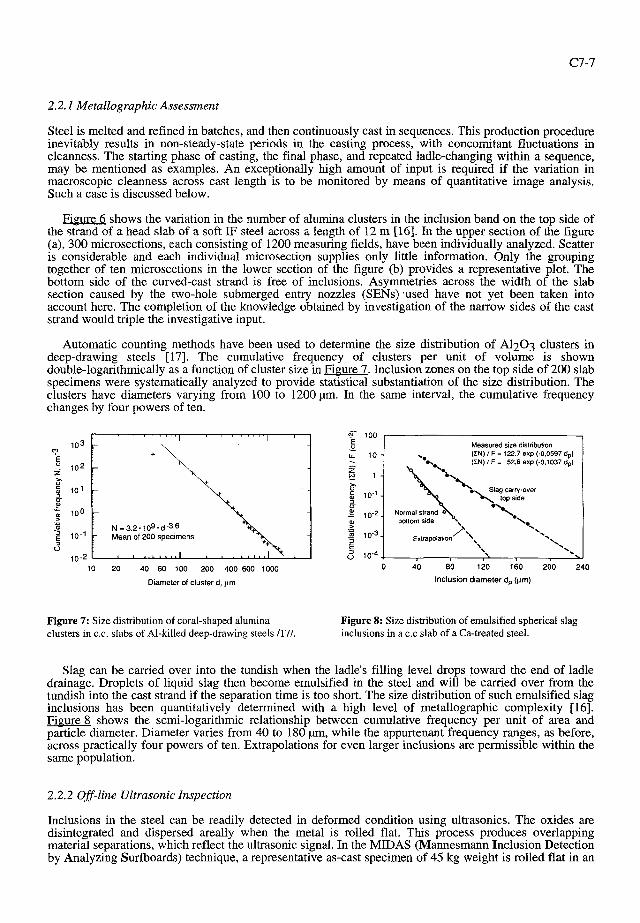
Automatic counting methods have been used to determine the size distribution of A1203 clusters in deep-drawing steels [17]. The cumulative frequency of clusters per unit of volume is shown double-logarithmically as a function of cluster size in Figure 7. Inclusion zones on the top side of 200 slab specimens were systematically analyzed to provide statistical substantiation of the size distribution. The clusters have diameters varying from 100 to 1200 pm. In the same interval, the cumulative frequency changes by four powers of ten.
40 60 100 200 400 600 1000
Diameter of cluster d, Hm
Measured size distribulion (EN) 1 F = 122.7 exp (-0.0597 dp) (IN) 1 F = 52.6 exp (-0.1037 do)
Slag carrpover *\ top side
*\ bottom side , I
' 0 . '\
\\\ \ '.
* 0 40 80 120 160 200 240
Inclusion diameter d, (prn)
Figure 7: Size distribution of coral-shaped alumina Figure 8: Size distribution of emulsified spherical slag clusters in C.C. slabs of Al-killed deep-drawing steels /17/. inclusions in a c.c slab of a Ca-treated steel.
Slag can be carried over into the tundish when the ladle's filling level drops toward the end of ladle drainage. Droplets of liquid slag then become emulsified in the steel and will be carried over from the tundish into the cast strand if the separation time is too short. The size distribution of such emulsified slag inclusions has been quantitatively determined with a high level of metallographic complexity [16]. Figure 8 shows the semi-logarithmic relationship between cumulative frequency per unit of area and particle diameter. Diameter varies from 40 to 180 pm, while the appurtenant frequency ranges, as before, across practically four powers of ten. Extrapolations for even larger inclusions are permissible within the same population.
2.2.2 Off-line Ultrasonic Inspection
Inclusions in the steel can be readily detected in deformed condition using ultrasonics. The oxides are disintegrated and dispersed areally when the metal is rolled flat. This process produces overlapping material separations, which reflect the ultrasonic signal. In the MIDAS (Mannesmann Inclusion Detection by Analyzing Surfboards) technique, a representative as-cast specimen of 45 kg weight is rolled flat in an

C7-8 JOURNAL DE PHYSIQUE IV
unconventional manner and during the rolling process is specially upset in the direction of casting [12,16]. The reduction ratio is 90 %. The strand cross-section is expanded tenfold. For ultrasonics inspection, 300 mm x 400 mm plate specimens are cut out of the inclusion zone. The remainder, which is clean and makes up 75 % of the representative sample, is discarded.
Distance x, mm Amplitude
in %
( Intervals of Number of1
Dimensions : 349 x 300 x 10.5 mm
Figure 9: Cartography of the ultrasonic indications of macroscopic inclusions in a MIDAS rolling specimen viewed from the narrow side of a contaminated C.C. slab (10 MHz probe SEB 10 K4, Ax = Ay = 1 mm, duration of inspection: 15 min.)
Figure 10: High-resolution repeat inspection in a small window with a narrower inspection grid of Ax = Ay = 0.2 mm, also showing comparison with a higher-frequency focussing probe. (a) Transducer SEB 10 K4, water delay path 0.1 mm, (b) Transducer IAP 15.6.2., water delay path 25 mm.
Figure 9 shows a coloured C plot of the narrow side of a heavily contaminated slab of a plate grade. Each spot indicates a macroscopic inclusion of larger than 80 pm in as-cast condition. The colour indicates specific intervals in amplitude. The total number of defects detected above the 15 % threshold is N = 11 18. The 10 MHz SEB 10 K4 probe used scans the test plate in 15 min. The effective scanning grid isAx=Ay = 1 mm.
This large-area high-speed scan can be used as the basis for a high-resolution repeat inspection using an IAP 15.6.2 focussing 15 MHz probe on a restricted 40 mmx 80 mm window. Figure 10 shows a coloured print-out of the inclusion distribution in the window and the appurtenant amplitude. A finer scanning grid of Ax = Ay = 0.2 mm was selected for this sensitive measurement. The smaller sonic beam naturally makes it possible to additionally detect smaller defects.
The extension of detectability toward smaller defects is, however, of no relevance for practical inspections, since a sufficient number of other methods exists for microscopic cleanness. The facility for high-speed orientational measurement for the purpose of detection of larger particles and clusters, the basic orientation of the MIDAS principle, on the other hand, is of great practical benefit and has enabled quite a few steelplants to improve their metallurgical and strand-casting practices in order to meet maximum cleanness specifications.
Systematic knowledge of macroscopic cleanness during the steady-state and non-steady-state phases of the process and during interruptions to normal operation makes it possible to classify strand-cast material into "ultra-clean", "regular" and "contaminated" categories at an early stage in the steelplant's production cycle. This selection process, wherever it becomes possible, e.g., in the case of cold-deformable deep-drawing steels or seamless mechanical tubes, permits the repeatable fulfillment of top cleanness requirements.
3. HIGH-PURITY FLAT PRODUCTS
The starting material for flat product is cast on slab-casters. The casting rates of modern machines are extremely high, and the residence time of the steel in the tundish correspondingly short. Little time remains for the separation of non-metallic inclusions. The high throughput rate results in severe convection and turbulence in the tundish, SEN and mould [18]. Inclusions are able to coagulate and agglomerate, casting slags to emulsify. Casting of clean slabs is therefore difficult in principle. To meet maximum standards, casters are equipped with a vertical section which promotes the removal of coarse inclusions and argon bubbles.
3.1 Super-Formabfe Sheet Steels
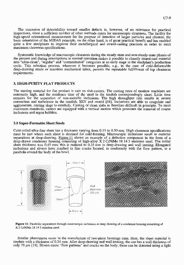
Cold-rolled ultra-fine sheet has a thickness varying from 0.15 to 0.50 rnrn. High cleanness specifications must be met where such sheet is destined for cold-forming. Macroscopic inclusions result in material separations at deep-drawing. Figure 11 shows an example of a defective component in the form of a deep-drawn condenser housing consisting of high-alloy X 2 CrNiMo 18 14 3 stainless steel. The initial sheet thickness was 0.45 mm; this is reduced to 0.25 mm in deep-drawing and wall ironing. Elongated inclusions and slivers have resulted in fine cracks located, in conformity with the flow pattern, in a parabola around the body of the bowl.
Figure 11: Parabolic separations through macroscopic inclus~ons at deep-drawing of a condenser housing consisting of X 2 CrNiMo 18 14 3 stainless steel.
Similar phenomena occur in the manufacture of two-piece beverage cans. Here, the sheet material is tinplate with a thickness of 0.24 mm. After deep-drawing and wall ironing, the can has a wall thickness of only 79 pm [19]. Slivers cause "flow patterns" and cracks on the body; these can be detected using a light

C7-10 JOURNAL DE PHYSIQUE IV
or pressure test [5]. In addition, inclusions cause flange cracks. The problem becomes even worse if the sheet thickness is further decreased. Failure rates are stated in ppm and are used as a measure of a steel producer's supply capabilities.
In the automotive industry, there is an increasing tendency toward one-piece forming of complicated pressed exposed components. Such applications necessitate the highest possible values of r > 2.5 for vertical anisotropy. The corresponding steels are known by the abbreviations Super-EDDQ and ULC/IF [20-221. In these steels, two of the purity criteria in Figure 1 have to be fulfilled: interstitial purity and macroscopic oxide cleanness. Ultra-low decarburization necessitates an oxygen surplus and provokes the formation of a large number of oxides upon deoxidation using aluminium. Cleanness defects in the form of slivers and pencil blisters may occur on the cold-rolled strip [23].
There are two explanations for pencil blisters: on the one hand, penetrating hydrogen recombines at the site of flat inclusions; or, argon bubbles laden with oxide inclusions are not welded shut during hot rolling, the gas subsequently expanding. The soft, "super-formable" ULC/IF steel bulges like a pencil pipe above the elongated or linear inclusions during recrystallization annealing. Blisters and slivers can be visually detected. In many cases, 100 % inspection by the steel manufacturer is not possible, for time reasons. Great importance therefore attaches to process control and monitoring, and to the selection process.
3.2 High-Precision Shadow Masks
Shadow masks consisting of high-purity soft magnetic steel perform an important function in colour TV and data-monitor tubes. Their working position is shown in Figure 12. The shadow mask is a thin foil in which as many as half a million slots are photochemically etched, depending on screen size. The shadow mask ensures that the three electron beams for red, green and blue always separately excite the corresponding phosphors on the glass face of the screen, and obscures the other two phosphors.
Glass face -
Electron beam
Figure 12: Shadow mask of a colour television picture tube for magnetic screening and limitation of the three electron beams for excitation and shading of the respective red, green and blue phosphors
Figure 13 shows scanning electron microscope images of a slotted shadow mask. The cold-rolled strip is generally reduced to a thickness of 100 to 250 pm. A thickness tolerance of 2.5 pn is adhered to. Liiders flow lines must be avoided. The slots have a conical geometry and are matched to beam deflection by tapering. Photochemical etching is accomplished with incredible precision in terms of slot position and geometry [24]. Oxide inclusions result in etching defects. The contour of the slots is then irregular, see the views from the gun-side (a) and the cone-side (b).
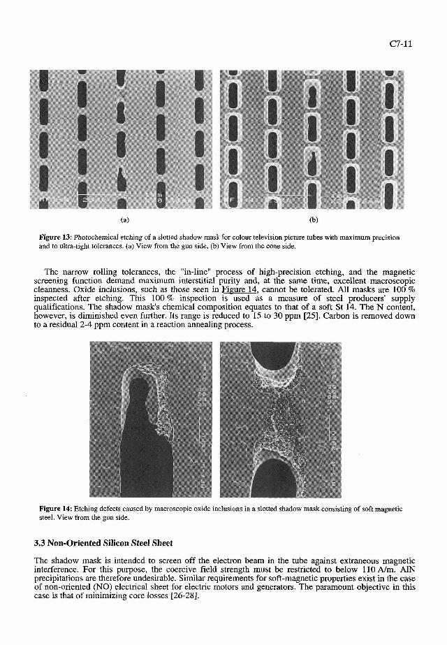
Figure 13: Photochemical etching of a slotted shadow mask for colour television picture tubes with maximum precision and to ultra-tight tolerances. (a) View from the gun side, (b) View from the cone side.
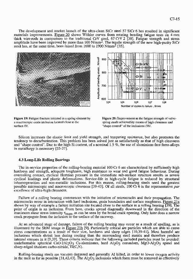
The narrow rolling tolerances, the "in-line" process of high-precision etching, and the magnetic screening function demand maximum interstitial purity and, at the same time, excellent macroscopic cleanness. Oxide inclusions, such as those seen in Fieure 14, cannot be tolerated. All masks are 100 % inspected after etching. This 100 % inspection is used as a measure of steel producers' supply qualifications. The shadow mask's chemical composition equates to that of a soft St 14. The N content, however, is diminished even further. Its range is reduced to 15 to 30 ppm [25]. Carbon is removed down to a residual 2-4 ppm content in a reaction annealing process.
Figure 14: Etching defects caused by macroscopic oxide inclusions in a slotted shadow mask consisting of soft magnetic steel. View from the gun side.
3.3 Non-Oriented Silicon Steel Sheet
The shadow mask is intended to screen off the electron beam in the tube against extraneous magnetic interference. For this purpose, the coercive field strength must be restricted to below 110 A/m. AlN precipitations are therefore undesirable. Similar requirements for soft-magnetic properties exist in the case of non-oriented (NO) electrical sheet for electric motors and generators. The paramount objective in this case is that of minimizing core losses [26-281.

C7-12 JOURNAL DE PHYSIQUE IV
The elements C, N, S and 0 are detrimental to soft-magnetic properties. Figure 15 shows, by way of example, the reduction in core losses P1.5 (Wkg) when N content is decreased. Inclusions and precipitations restrict the mobility of the domain walls and the achievement of optimum grain size within the 100-150 pm range. NO electrical sheet is alloyed up to 3.5 % Si and up to 1.0 % Ai. The following tramp element contents are customary for top-quality grades: C = 20 ppm, N < 20 ppm, S = 5 ppm and Ot = 7 ppm [26,27]. NO electrical sheet provides an outstanding example of high-purity steel, since it simultaneously fulfils several of the purity criteria defined above in Figure 1. The metallurgy for the assurance of such a high standard is correspondingly sophisticated.
2.2 20 25 30 35 LO L5 50 55
Nitrogen content, ppm
Figure 15: Core losses in non-grain-oriented NO electrical sheet as a function of nitrogen content 1271.
4. HIGH-PURITY LONG PRODUCT
Long steel product is melted in the form of BOF or EAF steel and then undergoes secondary metallurgical refining and casting on bloom or billet machines. Typical bloom formats are: 260 mm x 380 mm and 300 mm x 400 rnm. Bloom casters for large formats are sometimes equipped with a vertical section. This design principle, in combination with low withdrawal speeds, promotes the removal of coarse inclusions.
Typical long products involving high cleanness specifications include engineering steels for massive cold forming, e.g., for upsetting, extrusion, twisting, stranding, punching and for the drawing of wire, rods and tubes. Work hardening occurs in these shaping processes and may be locally extremely high, depending on the degree of deformation. Oxide inclusions also cause high stress peaks. Cracking and spalling are the result.
Rails, too, also demand high-purity steels. Greater axle loadings, shorter train headways, lower-radius curves and higher speeds all make their demands. Residual stresses caused by cyclical cold plastic deformation and local hardness peaks are superimposed on the wheelfrail oscillation cycle. Spalling, so-called "shelling", becomes inevitable if hard A1203 inclusions are additionally present in these critical areas, for instance on the inner edge of the outer rail in a curve. Al-free metallurgy is used to counter this fatigue problem [29].
4.1 High-Tensile Tire Cord
Experience demonstrates that cleanness is always critical when steels are rolled or drawn to minimum thicknesses and diameters. This is true both in the case of ultra-fine sheet and of ultra-fine wire. The size of the cold-formed material then begins to approach the size of the undeformable macroscopic inclusions.

The steel cord for automotive tires, providing support under heavy loads, is one of the steel industry's thinnest products [30-331. Figure 16 shows typical wire braids produced on modem double-twist stranding machines [34]. In this stranding process, the wire is not only spirally bent but also twisted about its own axis once every lay length. Bending and torsion extend into the plastic range. Manufacturing is made more difficult by the fact that this wire is becoming ever thinner and stron er. Ultra-high tensile 4 grades, for instance, are now approaching strengths of more than 3500NImm , the wire diameter decreasing to only 0.12 mm. Special demands are therefore made on the homogeneity and purity of the material.
I 71re cdrdl C-C~tent I Tensile strength W ~ r e dlameter I hllmm2 I m m
Figure 16: Typical steel cord designs produced on double- Figure 17: Conical fracture during twist-type stranding of twist wire-stranding machines, also showing strength steel cord wire, caused by a hard macroscopic spinel-type categories and diameters for various wire grades 130, 341. MgO - A1203 inclusion 130,311
NT HT
UHT
The wire may break during drawing or stranding. Figure 17 shows a conical fracture with a recessed residual fracture surface which occurred during stranding [30,31]. The fracture was initiated by an MgOeA1203 inclusion. This spinel has a high melting point, a high hardness and, in addition, is not deformable within the steel. The A1203 corundum has the same, extremely harmful properties. For this reason, "shape control" of inclusions in metallurgy is of vital importance for tire cord production [31]. The target of this modification takes the form of small oxide particles with a low melting point which are soft relative to the metal matrix and are readily deformable.
These Si-killed blooms appear to perform poorly on the basis of MIDAS ultrasonics results, see the C plot for a medium section of bloom shown in Figure 18a. The inclusions are harmless in this application, however, since the low-melting composition in the Ca0-Si02-Al203-MgO phase diagram was achieved. No hard constituents, which could be separated during deformation by "stripping" of the coexistent liquid phase, were precipitated in the inclusions. During rolling and drawing of the wire, the inclusions are size- reduced in such a way that they do not result in fracture. The favourable elastic properties of these soft oxides make a significant contribution to the avoidance of stress peaks [32,33].
0,70 - 0,74 0,80 - 0,85 0.86 - 0,90
Ultra-fine drawn wire is produced from high-alloy stainless steels and used for screens and fabrics. The high cleanness, both macroscopic and microscopic, required for these applications can be achieved only using the electro-slag remelting (ESR) process.
,",,,,,., 2700 - 2900 3000 - 3300
3500
> 0,175 > 0.150 > 0,120

C7-14 JOURNAL DE PHYSIQUE IV
4.2 High-Performance Valve Springs
Spring steels are characterized by their high elastic limit and yield strength, an adequate plastic deformation capacity and, above all, by their high fatigue strength and reliability. A long service-life is expected for the valve springs used in motor-vehicles. In addition, engine outputs and speeds are increasing. For this reason, additional thermal stability is also demanded. Valve-spring failure means "a vehicle stopped with engine damage".
(a) Tire-cord heat (b) Valve-spring heat
I
Width, mm + Width, mm - Figure 18: Cartographies of the ultrasonic indications in MIDAS rolling specimens of C.C. blooms of steels produced Al-free with shape control of the inclusions. (a) Tire-cord heat, (b) Valve-spring heat.
NTTlrecard
A new generation of SiCr valve-spring steels completely fulfils the above conditions and thus virtually excludes failures [35-381. These steels (SAE 9254; 57 SiCr 6) are produced, like steel cord, on the criteria of maximum cleanness and "shape control". Figure 18b shows the C plot using MIDAS for such a 57 SiCr 6 steel. The large number of ultrasonics indications is the result of harmless soft deformable inclusions caused by electromagnetic stirring during continuous casting. The most favourable inclusion types are silicates with triple tridymite + anorthite + wollastonite saturation and a low melting point of Tm = 1170" C (around 62 % SiO2 - 24 % CaO - 14 % Al203).
0.001
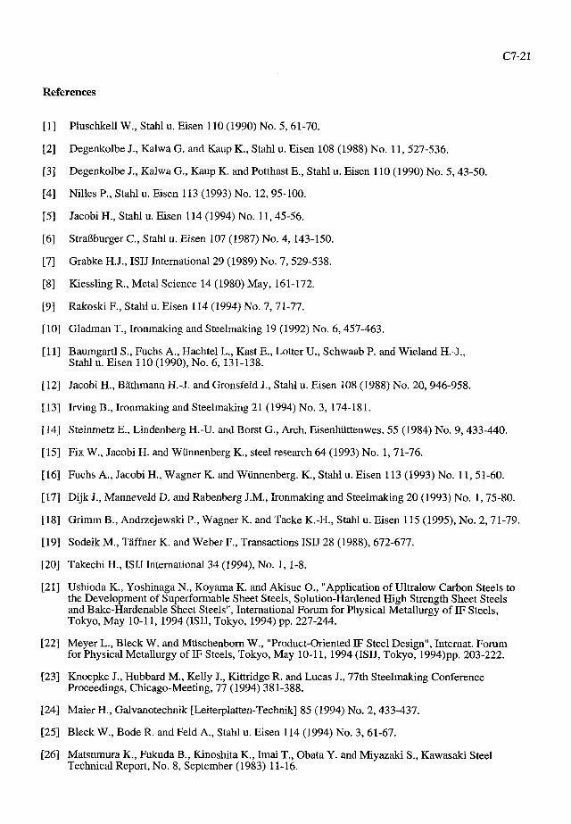
The service-life of high-tensile strength valve springs generally depends on surface finish and any hard oxides located close to the surface. Figure 19 shows a typical fatigue fracture in a spring steel [9]. The crack initiator was an oxide inclusion consisting, for instance, of A1203 alumina, MgOeA1203 spinel or SiO2 christobalite, etc. Notch sensitivity and the rapidity of crack propagation rise as the material's tensile strength increases. For this reason, the surface of valve-spring wire must exhibit no defects or damage, such as scoring, cracking, cratering, notches, pores or flakes. Decarburization must either be prevented or repaired in good time by means of "peeling".
0.85
SAE 9254
0.0037 0.20 0.03
0.57
0.50
1.46
0.007
0.69
0.009 0.02
0.003 0,011
0.008
0.001 0,0067 0.02 0.71 0.001
The development and market launch of the ultra-clean SiCr steel 57 SiCr 6 has resulted in significant materials improvements. Figure 20 shows Wohler curves from rotating bending fatigue tests on 4 mm thick wire-rods in comparison to the traditional CrV steel, 67 CrV 2 [38]. Fatigue strength and stress amplitude have been improved by more than 100 ~ / m m ~ . The tensile strength of the new high-purity SiCr steel has, at the same time, been raised from 1600 to 1900 ~ / m m 2 [35].
Figure 19: Fatigue fracture initiated in a spring element by Figure 20: Improvement in the fatigue strength of valve- a macroscopic oxide inclusion located close to the spring steels achieved.by means of high cleanness and surface 191. "shape control" of the inclusions 1381.
Silicon increases the elastic limit and yield strength, and tempering resistance, but also promotes the tendency to decarburization. This problem has been solved just as satisfactorily as that of high cleanness and "shape control". Due to the high Si content, of a nominal 1.5 %, the use of aluminium-free ferro-alloys in metallurgy is necessary [35-371.
4.3 Long-Life Rolling Bearings
The in-service properties of the rolling-bearing material 100 Cr 6 are characterized by sufficiently high hardness and strength, adequate toughness, high resistance to wear and good fatigue behaviour. During overrolling contact, cyclical Hertzian pressure in the immediate sub-surface structure results in severe cyclical loadings and plastic deformations. Service-life in high-cycle fatigue is reduced by structural inhomogeneities and non-metallic inclusions. For this reason, rolling-bearing steels need the greatest possible microscopic and macroscopic cleanness [39-431. Of all steels, 100 Cr 6 is the representative par excellence of ultra-high cleanness.
Failure of a rolling bearing commences with the initiation of microcracks and their propagation. The microcracks occur in interaction with hard inclusions, grain boundaries and surface roughness. Figure 21a shows by way of example a failure initiation site located close to the surface in a rolling bearing [39]. The point of origin is an inclusion. From here, cracks spread diagonally downward in the direction of the maximum shear stress intensity Tmax, as can be seen by the broad crack opening. Only later does a narrow crack propagate from the inclusion to the surface of the raceway.
At an advanced stage of damage, failure of the rolling bearing may occur as a result of spalling, as is illustrated by the SEM image in Figure 21b [9]. Particularly critical are particles which are able to cause stress concentrations as a result of their size, hardness and sharp edges [10,39-411. Most harmful are inclusions which shrink less during cooling than the surrounding steel matrix and therefore produce internal stresses in it [9,39]. These criteria indicate that the following included particles must be avoided: undeformable spherical Ca0.2A1203 Ca-aluminates, hard A1203 corundum, MgO.Al203 spinel and sharp-edged titanium carbo-nitride, Ti(C,N).
Rolling-bearing steels are vacuum degassed and generally A1 killed, in order to lower oxygen activity in the melt as far as possible [3 1,42,43]. The A1203 inclusions which form must be removed as effectively

C7-16 JOURNAL DE PHYSIQUE IV
Figure 21: Damage to a 100 Cr 6 rolling bearing steel during overtolIing contact (a) Failure initiation site at an inclusion located close to the surface 1391, (b) Spalling on the raceway surface 191
as possible in the ladle, tundish and mould. Agglomeration, in which the small particles coalesce to form larger clusters, should not be allowed to occur in the nozzles. As the histogram of oxygen contents in Figure 22a shows, Ot values of around 6 to 8 ppm can be achieved on a production scale. Inspection of mi>roscopic cleanness in conformity with ASTM E 45 and DIN 50 602 has, in addition, produced an excellent standard [42].
TiN shortens the fatigue life of bearings. For this reason, a permissible particle size has been defined. Figure 22b shows the maximum TiN size encountered per microsection and per test batch in random sampling. The specification permits a maximum of 25 particles larger than 10 pm, of which a maximum of three particles may be between 40 and 60 pm, on a surface area of 50 mm2. The diagram indicates that the scatter of the random samples is actually within the tolerances.
Ti contents I 30 ppm are also specified in high-fatigue strength rolling-bearing steels, in order to avoid the presence of harmful TiN. Titanium is primarily imported via ferrous alloys, and FeMn in particular. In the case of 100 Cr 6, containing 0.30 % Mn, the strict limits are always adhered to [42]: 80 % of heats
Total oxygen Content 0, , ppm Particle size of TIN , pm
Figure 22: Statistical analyses on Al-killed 100 Cr 6 rolling bearing steel produced in an EAF steelplant 1421. (a) Total oxygen contents within the scope of the specification Ot I 15 ppm; (b) Maximum TiN size encountered per microsection and test batch for Ti 530 ppm.

have Ti < 20 ppm, and 20 % have 20 < Ti < 30 ppm. In the case of the higher alloyed 100 CrMn 6 grade, containing 1.20 % Mn, the limits must inevitably be moved upward. 5 % of heats meet Ti < 20 %, 75 % are in the 20 < Ti < 30 ppm interval and 20 % in the 30 < Ti < 40 ppm range. In this and similar cases of exceptionally high requirements, the steel industry is dependent on rationally priced supplies of suitable ferro-alloys, additives and refractory materials.
5. HIGH-PURITY PIPES AND TUBES
In the steel tubing sector, it is necessary to differentiate between seamless and welded tubes. Seamless tubes are nowadays produced mainly from round C.C. billets cast on curved or rotary casters. Seamless tubes are widely used for conveyance of gas, water and heating fluids, in power generating plant and processing equipment engineering, in mechanical and plant engineering and for energy transmission on oil and gas fields.
Welded tubing is made from hot-rolled wide strip and plate. The starting material is C.C. slab which is thermo-mechanically rolled and treated. Large-diameter linepipes for transmission of oil and natural gas are made with diameters of up to 64" and wall thicknesses of up to 40 mm using the UOE process. Not infrequently, gas pipelines are laid in arctic regions or at great underwater depths and operated at an internal pressure of up to 100 bar. More and more frequently, the fluids conveyed contain highly corrosive constituents.
For most applications, tubes have to have good cleanness. In many cases, this is dictated by the need for piping system and pipeline safety. For both types of tubing, i.e. seamless and welded, there are also extreme specifications, however, the fulfillment of which constitutes a great challenge to both metallurgy and continuous-casting technology. Special developments for desulfurization of steel and sulfide shape control had their origins here and nowadays benefit all steel products.
Figure 23: Defects in the chromium plating of precision, mechanical and MBS tubes caused by macroscopic oxide inclusions. (a) Hydraulic ram cylinder, (b) Clothing hanger rod.
5.1 Precision Steel Tubes
In the past, cylindrical hollow machined components for road vehicles and other mechanical engineering applications were frequently cut from solid steel. Nowadays, precision tubes, the dimensions of which can closely approach those of the finished component, are available for this purpose. This more rational production route offers several advantages: more economical use of materials, shorter machining times and enhanced tool lives. Precision tubes, particularly cold-worked tubes, are notable for high dimensional accuracy and a smooth surface, which in many cases is refined by means of hard chromium-plating following machining.

C7-18 JOURNAL DE PHYSIQUE IV
Such precision tubes are suitable for use as cylinders and pistons in hydraulic and pneumatic force transmission and control systems. Great demands are made on the manufacturing standard of the working cylinder. Cleanness defects will either not be covered by the layer of chromium, or will impair its adhesion. Even relatively small oxide inclusions can seriously disrupt chromium plating. Figure 23 shows two typical examples of this. Defects and spalling of the chromium layer damage the piston seals, resulting in leaks and failure. Hydraulic pit props for face support in combination with hydraulically adjustable shields, miracles of flexibility, are a typical application.
Figure 24:Macroscopic oxide inclusion as the cause of a defective pattern on a calendering roll for embossing of paper surfaces.
Precision tubes are also used for the manufacture of rolls for the paper industry. Figure 24 shows the defective engraved surface of a calendering roll caused by a non-metallic inclusion. The function of such a roll is the embossing of a specific topography on the paper at the end of the production process. A rhombic pattern is shown here by way of example. The entire finished surface of such paper rolls is examined under the microscope for defects. As in the case of chromium-plated hydraulic tubing, a zero defect rate is mandatory.
In the case of precision and mechanical tubes, a further complicating factor is that the material is required to have good machining characteristics in addition to a good oxide cleanness. The combination of these contradictory criteria is achieved by means of a controlled S content of 0.025 % coupled with A1 deoxidation and subsequent Ca treatment [44,45]. These provisions are important preconditions for rational and trouble-free machining on fully automated CNC machine tools.
5.2 HIC Resistant Linepipe
The prime emphases in the development of ultra-clean large-diameter linepipe steels for conveyance of corrosive sour gas are found in extreme lowering of the S content and consistent shape control of the sulfides [44,45]. Fracture toughness and reduction of area were improved and their anisotropy a priori eliminated in the rolled product. The resistance of the material to initiation and propagation of cracks was enhanced. Lamellar tearing under exposure to load in the direction of plate thickness was avoided [2,3,6]. Finally, the development path was crowned with resistance to hydrogen-induced cracking (HIC) [46].
Resistance to HIC presupposes total avoidance of MnS in the as-cast product. The danger point is the slab center, which is susceptible to segregation. Local enrichment of dissolved residual sulfur must not be permitted, however. For this reason, the sulfur is first lowered to contents < 10 ppm and any sulfur still present stably fixed to Ca. Figure 25 shows a concentration diagram for Ca and S in the center segregation range of a sour-gas resistant steel slab. A specimen was sectioned layer-by-layer and emission spectral analysis repeated 100 times for center transition on the same piece.

Ca and S are fixed in the form of oxysulfides and Ca aluminates. The scatter of the measuring points reflects the natural fluctuation of the inclusion population's chemical composition. The central point of concentration distribution correlates to contents of 26 ppm Cao and 9.5 ppm So. The average atomic concentration ratio, Ca to S, is ACR = 2.19. The concentration distribution of dots does not overlap into the critical Ca deficiency range of ACR I 1, in which MnS unavoidably exists. Free residual sulfur which could have segregated at the center proved in retrospect not to have been present.
ACR = Atomic concentration ratio
Sulphur content , at. - ppm
- ACR
Sulphur content, wt. - ppm
Figure 25:Avoidance of MnS inclusions in the centre of a slab of a sour-gas resistant linepipe steel achieved by means of ultra-low desulfurization and "shape control" of inclusions using calcium.
2,19 1 2,74 1 26.0 1 9.5 1 9,2 [ 10,9 1 0.84 Cao/ So
The detrimental role of MnS in large-diameter linepipe steels is explained by its special form of behaviour: it both deforms and contracts to a greater extent than the metal matrix, with the result that the phase interface opens after cooling [lo]. This produces fine voids and material separations which, on the one hand, impair toughness and, on the other hand, act as traps for absorbed hydrogen. The hydrogen is able to recombine at these sites, create a high internal pressure and thus break up the banded structure. Flat-area oxide accumulations in the rolled material act in a similar way as traps for the hydrogen. They are also capable of causing HIC cracks and sub-surface blisters. Good oxide cleanness effectively counteracts these causes of cracking [44-481.
High-purity large-diameter line pipe steels for conveyance of sour-gas are notable for ultra-low P, S, 0 and N contents. The term "ppm metallurgy" is certainly appropriate to describe the situation. Cleanness and homogeneity will, in the future, be the most important preconditions for thicker-walled pipelines. New knowledge has been obtained regarding Ca in steel. Figure 26 shows a concentration profile for total Ca at the center of a slab. All the other elements (C, P, Nb, Mn, Si and Cu) segregate positively, whereas
Cao So - 0,
- S
- - 0 , l S

C7-20 JOURNAL DE PHYSIQUE IV
Ca manifests a depletion in the same interval. This observation can be explained by partially dissolved [Ca] of approx. 5 ppm at the tip of the liquid pool. When shrinkage holes form and ferrostatic pressure drops during final solidification, the dissolved [Ca] escapes as a vapour from the residual melt into the cavities. Spectral analysis is then unable to detect it on the inner surfaces of cavities.
- Towards Distance from slab centre , mm Towards - bottom side top side
Figure 26: Calcium-depletion at the centre of a slab of a sour-gas resistant linepipe steel with associated occurrence of pronounced centre segregation and microporosity
6. CONCLUSIONS
1,83 1 2,29 1 19.5 1 8.5 1 13,O 1 7.6 1 1.71
- S
- 0,
As top-quality industrial products, high-purity steels are a reality and have become an integral component of our daily lives: even colour televisions cannot exist without steel, not to mention motor-vehicles and numerous other applications which form the very basis of our modern industrial and service society. Large tonnages of high-purity steels are produced in BOF and electric-melting steelplants and subsequently returned to the materials cycle by means of recycling.
- - 41s
- ACR
The present summarizing report discusses six criteria for steel purity: Interstitial and substitutional purity, grain-boundary purity, microscopic and macroscopic cleanness and "shape control" of inclusions, with the objective of converting harmful particles to harmless particles. A selection of flat and long products with extreme materials specifications are used to illustrate the way these criteria are demanded, either individually or in combination.
Cao CaolSo
Macroscopic oxide cleanness remains a great challenge but also a great development potential: even now, it restricts steelmaking consistency and yield here and there; even now, it is difficult to characterize and control; as a scientific term, it is not clearly defined and cannot be precisely verified in the theoretical analysis; and yet its importance is felt everywhere in the metallurgy, production and use of steels.
So
The problem is a statistical one: that of the needle in the haystack! The steel industry meets random occurrences with consistent process monitoring, control and automation systems, comprehensive data evaluation and stringent control of raw materials and aIloying elements. Innovations in process engineering aimed at shortening process routes, with near-net shape casting at the head, and the anticipated higher rates of scrap recycling, with concomitant increases in impurity contents, will, on the other hand, ensure that the challenge of cleanness always remains!
References
[I] Plusc&ell W., Stahl u. Eisen 110 (1990) No. 5,61-70.
[2] Degenkolbe J., Kalwa G. and Kaup K., Stahl u. Eisen 108 (1988) No. 11,527-536.
[3] Degenkolbe J., Kalwa G., Kaup K. and Potthast E., Stahl u. Eisen 110 (1990) No. 5,43-50.
[4] Nilles P., Stahl u. Eisen 113 (1993) No. 12,95-100.
151 Jacobi H., Stahl u. Eisen 114 (1994) No. 11,4556.
[6] StraBburger C., Stahl u. Eisen 107 (1987) No. 4, 143-150.
[7] Grabke H.J., ISIJ International 29 (1989) No. 7,529-538.
[8] Kiessling R., Metal Science 14 (1980) May, 161-172.
[9] Rakoski F., StahI u. Eisen 1 14 (1994) No. 7, 71-77.
[lo] Gladman T., Ironmaking and Steelmaking 19 (1992) No. 6,457-463.
[ l l ] Baumgartl S., Fuchs A., Hachtel L., Kast E., Lotter U., Schwaab P. and Wieland H.-J., Stahl u. Eisen 1 10 (1990), No. 6, 131-138.
[12] Jacobi H., Bathmann H.-J. and Gronsfeld J., Stahl u. Eisen 108 (1988) No. 20,946-958.
[13] Irving B., Ironmaking and Steelmaking 21 (1994) No. 3, 174-181.
[I41 Steinmetz E., Lindenberg H.-U. and Borst G., Arch. Eisenhiittenwes. 55 (1984) No. 9,433-440.
[15] Fix W., Jacobi H. and Wiinnenberg K., steel research 64 (1993) No. 1,71-76.
[16] Fuchs A., Jacobi H., Wagner K. and Wiinnenberg. K., Stahl u. Eisen 1 13 (1993) No. 1 1 , 5 1-60.
[I71 Dijk J., Manneveld D. and Rabenberg J.M., Zronmaking and Steelmaking 20 (1993) No. 1,75-80.
[18] Grimrn B., Andrzejewski P., Wagner K. and Tacke K.-H., Stahl u. Eisen 115 (1995), No. 2,71-79.
[19] Sodeik M., Taffner K. and Weber F., Transactions ISIJ 28 (1988), 672-677
[20] Takechi H., ISIJ International 34 (1994), No. 1, 1-8.
[21] Ushioda K., Yoshinaga N., Koyama K. and Akisue O., "Application of Ultralow Carbon Steels to the Development of Superformable Sheet Steels, Solution-Hardened High Strength Sheet Steels and Bake-Hardenable Sheet Steels", International Forum for Physical Metallurgy of IF Steels, Tokyo, May 10-1 1, 1994 (ISIJ, Tokyo, 1994) pp. 227-244.
[22] Meyer L., Bleck W. and Miischenborn W., "Product-Oriented IF Steel Design", Internat. Forum for Physical Metallurgy of IF Steels, Tokyo, May 10-11, 1994 (ISIJ, Tokyo, 1994)pp. 203-222.
[23] Knoepke J., Hubbard M., Kelly J., Kittridge R. and Lucas J., 77th Steelmaking Conference Proceedings, Chicago-Meeting, 77 (1994) 381-388.
1241 Maier H., Galvanotechnik [Leiterplatten-Technik] 85 (1994) No. 2,433-437.
[25] Bleck W., Bode R. and Feld A., Stahl u. Eisen 114 (1994) No. 3,61-67.
[26] Matsumura K., Fukuda B., Kinoshita K., Imai T., Obata Y. and Miyazaki S., Kawasaki Steel Technical Report, No. 8, September (1983) 11-16.

C7-22 JOURNAL DE PHYSIQUE IV
[27] Meichsner W. and Weber R.A., Thyssen Technische Berichte (1990) No. 1, 13-34.
1281 Bleck W. and Miischenborn W., Thyssen Technische Berichte (1992) No. 1,81-90.
[29] Kast E., Schmedders H., Sieben N. and Wick K., Thyssen Technische Berichte (1993) No. 1,l-17.
1301 Boeckers T., Brand W.-D., Grootaarts M., Heidelauf T., Schiitz C.-H. and Specht R., Thyssen Technische Berichte (1986) No. 2,223-232.
[31] Richter H., Rzepczyk H. and Tembergen D., Stahl u. Eisen 115 (1995) No. 5,83-88.
[32] Maeda S., Soejima T., Saito T., Matsumoto H., Fujimoto, H. and Mimura T., 72nd Steelmaking Conference Proceedings, Chicago-Meeting, 72 (1989) 379-385.
[33] Takahashi T., Ochiai I. and Satoh H., Nippon Steel Technical Report No. 53, April (1992) 101- 106.
[34] Poida M., Wire Journal International, February (1992) 97- 10 1.
[35] Ohshiro T., Ikeda T., Matsuyama H., Okushima S., Oki Y. and Ibaraki N., Stahl u. Eisen 109 (1989) NO. 21, 1011-1015.
[36] Hagiwara T., Kawami A., Ueno A., Kido A., Urbancic M.J. and Friedel R.D., Wire Journal International, April (1991) 29-34.
[37] Kawahara J., Tanabe K., Banno T. and Yoshida M., Wire Journal International, November (1992) 55-6 1.
[38] Barthold G. and Rakoski F., "Neue Werkstoffiundliche Entwicklungen beim Ventilfederstahl", DVM-Tag 1994, Bauteilt94, DIE FEDER, Berlin, May 4-6, 1994. Dieselben: Draht 46 (1995), No. 4, 191-197.
[39] Bohmer H.-J., Materialpriifung 36 (1994) No. 1-2, 16-20.
[40] Mannot J., Cogne J.Y. and HCritier B., Revue de MCtallurgie-CIT, October (1986) 761-769.
[41] Saleil J., Gatellier C., Zbaczyniak Y., Duplomb G., Damie Ph. and Cecconi R., Revue de MCtallurgie-CIT, April (1993) 479-486.
[42] Kremer K.-J., Jung H.-P., Peschke G. and Rakoski F., "Advances in the Production of Bearing Steels by Modern Secondary Metallurgy and Continuous Casting", Creative Use of Bearing Steels, ASTM STP 1195, Hoo J.C.C., Ed., American Society for Testing and Materials, Philadelphia, 1993,pp. 271-283.
[43] Baum R., Bohnke K., Otto J. and Pflipsen H.D., "Improved Properties of Bearing Steels by Advanced Metallurgical Processing", Creative Use of Bearing Steels, ASTM STP 1195, Hoo. J.C.C., Ed., American Society for Testing and Materials, Philadelphia, 1993, pp. 252-270.
[44] Kading G., Wierner H.-E. and Fix W., "Vacuum Tank Degassing for the Production of Tube Steels at Hiittenwerke Krupp Mannesmann", Proceedings The Sixth International Iron and Steel Congress, Nagoya, October 21-26, 1990, Ed., ISIJ, Vol. 3, Steelmaking I, pp. 619-628.
[45] Bannenberg N., Stahl u. Eisen 112 (1992), No. 7,83-89.
[46] Giirtner A.W., Graf M.K. and Hillenbrand H.G., "A Producer's View of Large Diameter Linepipe in the Next Decade", Proceedings The International Conf. on Pipeline Reliability, Calgary, June 2-5, 1992, Ed., CANMET, Gulf Publishing Company, Houston (1992) Paper III-1-1/15.
[47] Debiesme B., Poissonnet I., Choquet P. and Penet F., Revue de MCtallurgie-CIT, March (1993) 387-394.
[48] Bowness M.M. and Davies R.E., "The Production of High Purity Steels at British Steel Teesside Works", Proceedings 1. European Oxygen Steelmaking Congress, EOSC '93, Dusseldorf, June 21- 23, 1993, Eds. VDEh and CRM, 1993, pp. 9-16.


![The Electrochemical Characteristics of Cr30Mo2 Ultra Pure ...electrochemsci.org/papers/vol8/80100887.pdfgrades ferritic stainless steels (w [C+N]≤150×10-6). Ultra purity Cr18Mo2,](https://img.dokumen.tips/doc/110x75/60cf6aa9d287ae2aa841a4b2/the-electrochemical-characteristics-of-cr30mo2-ultra-pure-grades-ferritic-stainless.jpg)


![[60]Fullerene for Medicinal Purposes, A Purity Criterion](https://img.dokumen.tips/doc/110x75/61f8f1f7ac4c6661b743e45b/60fullerene-for-medicinal-purposes-a-purity-criterion-.jpg)