Embed Size (px)
Citation preview
Centrifugal Pump
Multitec / Multitec-RO
High-pressure Ring-section Pump
Type Series Booklet

Legal information/Copyright
Type Series Booklet Multitec / Multitec-RO
All rights reserved. The contents provided herein must neither be distributed, copied, reproduced,edited or processed for any other purpose, nor otherwise transmitted, published or made available to athird party without the manufacturer's express written consent.
Subject to technical modification without prior notice.
© KSB SE & Co. KGaA, Frankenthal 11/04/2018
Contents
Centrifugal Pumps ............................................................................................................................................ 4Multistage High-pressure Centrifugal Pumps .......................................................................................................................... 4
Multitec/Multitec-RO ........................................................................................................................................................... 4Main applications........................................................................................................................................................... 4Fluids handled ................................................................................................................................................................ 4Operating data............................................................................................................................................................... 4Designation .................................................................................................................................................................... 4Design details ................................................................................................................................................................. 5Materials ......................................................................................................................................................................... 5Technical description ..................................................................................................................................................... 6Operating ranges by installation type.......................................................................................................................... 8Product benefits ............................................................................................................................................................. 9Acceptance tests and warranty ..................................................................................................................................... 9Pressure and temperature limits ................................................................................................................................. 10Materials ....................................................................................................................................................................... 12Seal codes for the mechanical seal.............................................................................................................................. 16Seal codes for the gland packing................................................................................................................................ 17Technical data .............................................................................................................................................................. 18Noise characteristics ..................................................................................................................................................... 18Selection Charts............................................................................................................................................................ 20Drive.............................................................................................................................................................................. 23Dimensions ................................................................................................................................................................... 24Flange design (standard) ............................................................................................................................................. 31Nozzle positions ........................................................................................................................................................... 32General assembly drawing with list of components (example) ................................................................................ 33
Contents
3

Centrifugal PumpsMultistage High-pressure Centrifugal Pumps
4 Multitec/Multitec-RO
Centrifugal Pumps
Multistage High-pressure Centrifugal Pumps
Multitec/Multitec-RO
The product illustrated as an example may include optionsincurring a surcharge.
Main applications▪ Water supply systems
▪ Drinking water supply
▪ Pressure boosting
▪ General irrigation systems
▪ Fossil-fuelled power stations
▪ Hot-water supply
▪ Condensate transport
▪ Boiler feed applications
▪ Heating systems
▪ Filtering systems
▪ Fire-fighting systems
▪ Snow-making systems
▪ Washing plants
▪ Industrial plants
▪ Desalination plants
▪ Geothermal plants
▪ Heat recovery systems
Fluids handled▪ Water
▪ Drinking water
▪ Feed water
▪ High-temperature hot water
▪ Condensate
▪ Fire-fighting water
▪ Solvents
▪ Lubricants
▪ Fuels
▪ Cooling water
▪ Water/oil emulsions
▪ Seawater
▪ Thermal water
Operating data
Operating properties
Characteristic Value
Size DN 32 - 250Flow rate Q [m3/h] ≤ 1500
Q [l/s] ≤ 417Head H [m] ≤ 10001)
Fluid temperature T [°C] ≥ -10
≤ +2001)
Operating pressure p2 [bar]2) ≤ 1001)
Designation
Example: Multitec3) A 32/8E-2.1 12.167 (SP)
Designation key
Code Description
Multitec Type seriesA Installation type32 Nominal discharge nozzle diameter [mm]8E No. of stages / impeller combination2.1 Hydraulic system12 Material code167 Seal codeSP Code for special variants (optional)
Example: Multitec-RO4) A 100/5-8.1 31.80
Key to the designation
Code Description
Multitec-RO Type seriesA Installation type100 Nominal discharge nozzle diameter [mm]5 Number of stages8.1 Hydraulic system31 Casing material (duplex stainless steel)80 Seal code
1) Only for individual sizes/designs2) The sum of inlet pressure and shut-off head must not exceed the value indicated.3) Code: MTC4) Code: MTC-RO
Centrifugal PumpsMultistage High-pressure Centrifugal Pumps
5Multitec/Multitec-RO
Design details
Design▪ Multistage centrifugal pump in ring-section design
▪ Horizontal installation in long-coupled or close-coupleddesign
▪ Vertical installation in close-coupled design or withuniversal joint shaft
Pump casing▪ Suction casing: axial or radial
▪ Radial suction casing and discharge casing: nozzles can beturned in steps of 90°
▪ Flanges to EN and ASME (holes and flange facing)
▪ Identical seal housing for gland packing and mechanicalseal
▪ Stage casings, discharge casings and seal housing sealed byconfined O-rings
Drive▪ 50 Hz and 60 Hz electric motor
▪ Can be driven by diesel engine or turbine
Impeller type▪ Closed radial impeller with multiply curved vanes
Bearings▪ Fixed bearing, drive end: rolling element bearing
▪ Radial bearing, non-drive end: either plain bearing orrolling element bearing, depending on the type ofinstallation
▪ Rolling element bearing grease or oil lubricated
▪ Plain bearing lubricated by fluid handled
▪ Self-aligning
CouplingLong-coupled design:
▪ Flexible coupling with or without spacer
Close-coupled design:
▪ Up to DN 65 with rigid coupling
Coupling guardStandard:
▪ Coupling guard, cylindrical
Optional:
▪ Coupling guard, tread-proof
Shaft seal▪ Uncooled gland packing, with or without barrier fluid
▪ Standardised mechanical seal to EN 12756
▪ Cartridge mechanical seal
Materials▪ Casing: grey cast iron, nodular cast iron, steel, stainless
steel, duplex stainless steel, super duplex stainless steel
▪ Hydraulic system: grey cast iron, bronze, stainless steel,duplex stainless steel, super duplex stainless steel
Centrifugal PumpsMultistage High-pressure Centrifugal Pumps
6 Multitec/Multitec-RO
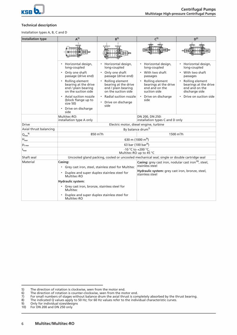
Technical description
Installation types A, B, C and D
Installation type A5) B5) C5) D6)
▪ Horizontal design,long-coupled
▪ Only one shaftpassage (drive end)
▪ Rolling elementbearing at the driveend / plain bearingon the suction side
▪ Axial suction nozzle(block flange up tosize 50)
▪ Drive on dischargeside
▪ Horizontal design,long-coupled
▪ Only one shaftpassage (drive end)
▪ Rolling elementbearing at the driveend / plain bearingon the suction side
▪ Radial suction nozzle
▪ Drive on dischargeside
▪ Horizontal design,long-coupled
▪ With two shaftpassages
▪ Rolling elementbearings at the driveend and on thesuction side
▪ Drive on dischargeside
▪ Horizontal design,long-coupled
▪ With two shaftpassages
▪ Rolling elementbearings at the driveend and on thedischarge side
▪ Drive on suction side
Multitec-RO: installation type A only
DN 200, DN 250:installation types C and D only
Drive Electric motor, diesel engine, turbineAxial thrust balancing By balance drum7)
Qmax8) 850 m3/h 1500 m3/h
Hmax 630 m (1000 m9))
p2 max 63 bar (100 bar9))
tmax -10 °C to +200 °C,Multitec-RO up to 45 °C
Shaft seal Uncooled gland packing, cooled or uncooled mechanical seal; single or double cartridge sealMaterial Casing:
▪ Grey cast iron, steel, stainless steel for Multitec
▪ Duplex and super duplex stainless steel forMultitec-RO
Hydraulic system:
▪ Grey cast iron, bronze, stainless steel forMultitec
▪ Duplex and super duplex stainless steel forMultitec-RO
Casing: grey cast iron, nodular cast iron10), steel,stainless steel
Hydraulic system: grey cast iron, bronze, steel,stainless steel
5) The direction of rotation is clockwise, seen from the motor end.6) The direction of rotation is counter-clockwise, seen from the motor end.7) For small numbers of stages without balance drum the axial thrust is completely absorbed by the thrust bearing.8) The indicated Q values apply to 50 Hz; for 60 Hz values refer to the individual characteristic curves.9) Only for individual sizes/designs10) For DN 200 and DN 250 only
Centrifugal PumpsMultistage High-pressure Centrifugal Pumps
7Multitec/Multitec-RO
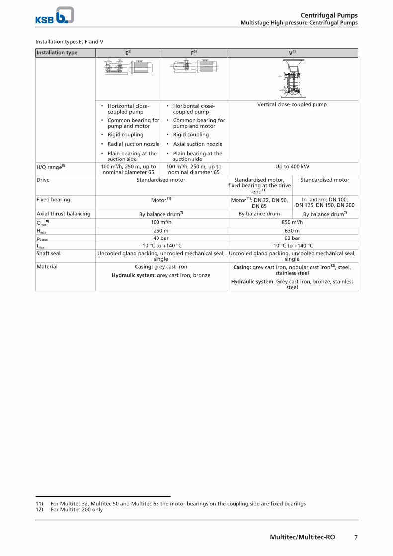
Installation types E, F and V
Installation type E5) F5) V5)
▪ Horizontal close-coupled pump
▪ Common bearing forpump and motor
▪ Rigid coupling
▪ Radial suction nozzle
▪ Plain bearing at thesuction side
▪ Horizontal close-coupled pump
▪ Common bearing forpump and motor
▪ Rigid coupling
▪ Axial suction nozzle
▪ Plain bearing at thesuction side
Vertical close-coupled pump
H/Q range8) 100 m3/h, 250 m, up tonominal diameter 65
100 m3/h, 250 m, up tonominal diameter 65
Up to 400 kW
Drive Standardised motor Standardised motor,fixed bearing at the drive
end11)
Standardised motor
Fixed bearing Motor11) Motor11): DN 32, DN 50,DN 65
In lantern: DN 100,DN 125, DN 150, DN 200
Axial thrust balancing By balance drum7) By balance drum By balance drum7)
Qmax8) 100 m3/h 850 m3/h
Hmax 250 m 630 mp2 max 40 bar 63 bartmax -10 °C to +140 °C -10 °C to +140 °CShaft seal Uncooled gland packing, uncooled mechanical seal,
singleUncooled gland packing, uncooled mechanical seal,
singleMaterial Casing: grey cast iron
Hydraulic system: grey cast iron, bronze
Casing: grey cast iron, nodular cast iron12), steel,stainless steel
Hydraulic system: Grey cast iron, bronze, stainlesssteel
11) For Multitec 32, Multitec 50 and Multitec 65 the motor bearings on the coupling side are fixed bearings12) For Multitec 200 only
Centrifugal PumpsMultistage High-pressure Centrifugal Pumps
8 Multitec/Multitec-RO
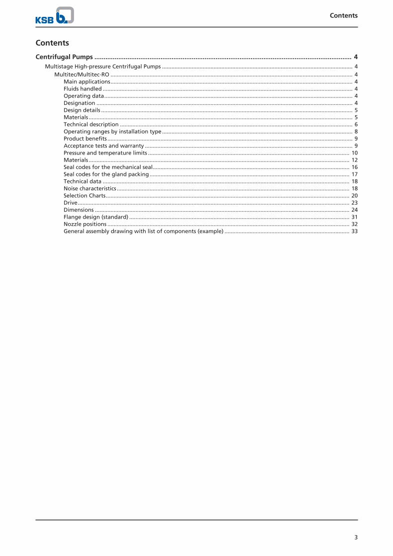
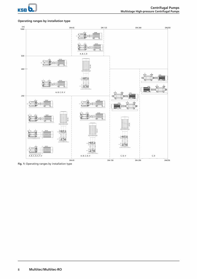
Operating ranges by installation type
[m]
630
400
250
051ND56ND
A, B, C, D, E, F, V C, D, V C, D
A, B, C, D, V
A, B, C, D, V
A, B, C, D
1000521ND56ND
020ND
020ND
250DN
250DN
Fig. 1: Operating ranges by installation type
Centrifugal PumpsMultistage High-pressure Centrifugal Pumps
9Multitec/Multitec-RO
Product benefits▪ Space-saving compact design with axial inlet and product-
lubricated plain bearing
▪ Flexible, best matching adaptation to system condition byvariety of installation types and variable nozzle position
▪ Low NPSH value, improved suction behaviour andoperating reliability for suction lift operation by specialsuction impeller
▪ Optimised efficiencies and reduced operating costs bynewly developed hydraulic system
▪ Versatile use by broad range of installation types,materials and shaft seals
▪ Optimum selection for fluid to be pumped and operatingconditions by large choice of materials
▪ High resistance by casing wear rings / closing discs made ofcorrosion-resistant material, economical and easy toreplace
▪ Shaft protected from wear by shaft protecting sleevemade of stainless steel
▪ Axial thrust balancing by balance drum– Low bearing load at changing operating condition– Long life of rolling element bearings and shaft seals– Use of standardised seals due to lower pressure in the
shaft seal chamber
▪ Longer service life, higher operating reliability, loweroperating costs, maintenance costs and investment costsby maintenance-free, robust plain bearing made of siliconcarbide, also suitable for operation with frequent starts/stops.
▪ Service-friendly by bearing assembly and mechanical sealbeing easy to dismantle
Acceptance tests and warranty
Certificates / inspections/ acceptance tests on request:▪ Test reports 2.2 to EN 10204 for pressure-retaining
components, shaft and impellers
▪ Hydrostatic pressure test of pressure-retainingcomponents
▪ Balancing test
▪ Hydraulic tests:– Performance test to ISO 9906 or Hydraulic Institute– NPSH test– Vibration test– Bearing temperature measurement
▪ Strip test
▪ Dimensional inspection
▪ Coating inspection
▪ Final inspection and testing
Centrifugal PumpsMultistage High-pressure Centrifugal Pumps
10 Multitec/Multitec-RO
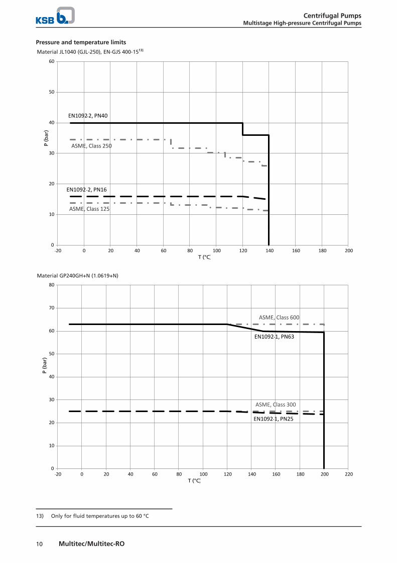
Pressure and temperature limits
Material JL1040 (GJL-250), EN-GJS 400-1513)
0
10
20
30
40
50
60
-20 0 20 40 60 80 100 120 140 160 180 200
EN1092-2, PN40
ASME, Class 250
EN1092-2, PN16
ASME, Class 125
P (b
ar)
T (°C)
Material GP240GH+N (1.0619+N)
0
10
20
30
40
50
60
70
80
-20 0 20 40 60 80 100 120 140 160 180 200 220
EN1092-1, PN63
EN1092-1, PN25
ASME, Class 600
ASME, Class 300
P (b
ar)
T (°C)
13) Only for fluid temperatures up to 60 °C
Centrifugal PumpsMultistage High-pressure Centrifugal Pumps
11Multitec/Multitec-RO
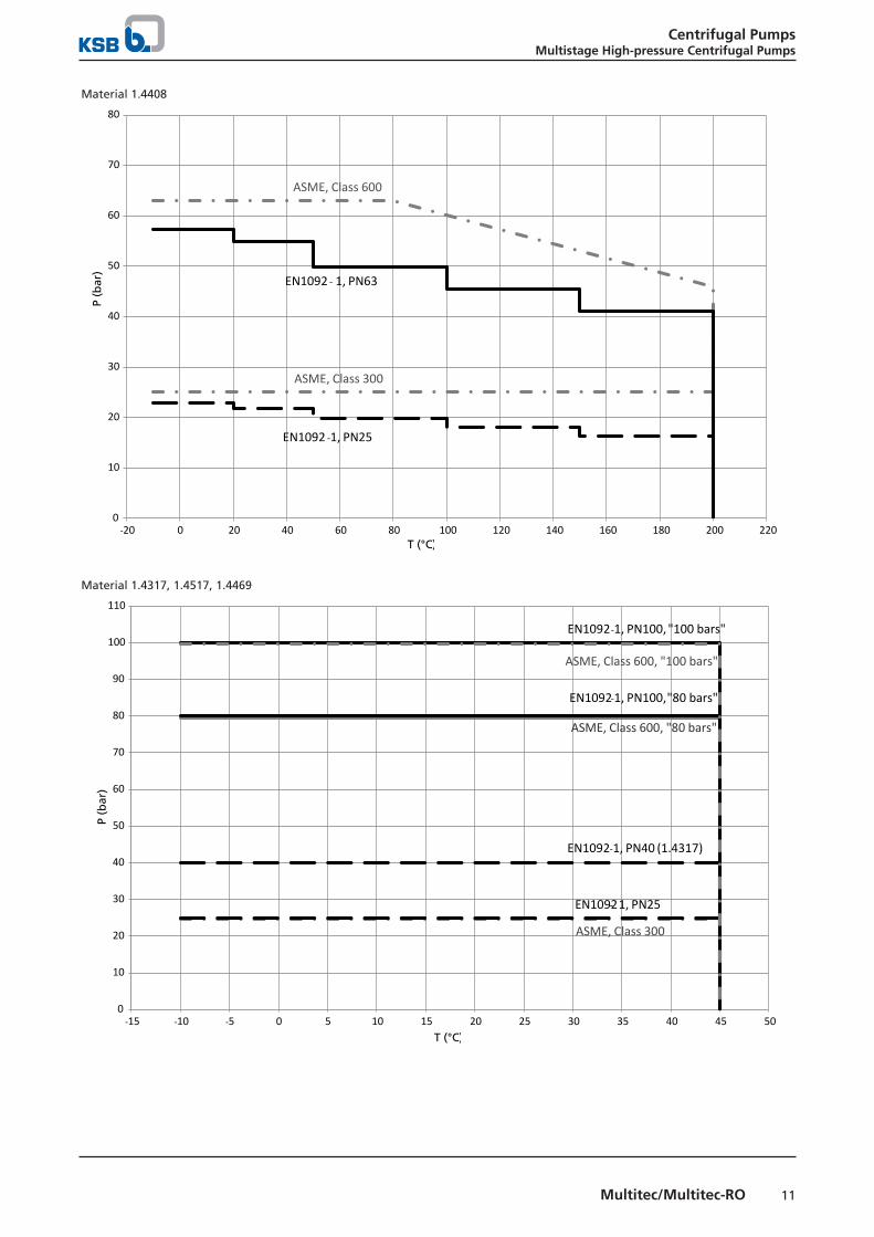
Material 1.4408
0
10
20
30
40
50
60
70
80
-20 0 20 40 60 80 100 120 140 160 180 200 220
T (°C)
ASME, Class 600
ASME, Class 300
EN1092 - 1, PN63
EN1092 -1, PN25
P (b
ar)
Material 1.4317, 1.4517, 1.4469
0
10
20
30
40
50
60
70
80
90
100
110
-15 -10 -5 0 5 10 15 20 25 30 35 40 45 50
EN1092-1, PN100, "100 bars"
ASME, Class 600, "100 bars"
EN1092-1, PN100, "80 bars"
ASME, Class 600, "80 bars"
EN1092-1, PN40 (1.4317)
EN1092- 1, PN25
ASME, Class 300
T (°C)
P (b
ar)

Centrifugal PumpsMultistage High-pressure Centrifugal Pumps
12 Multitec/Multitec-RO
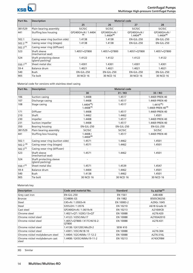
Materials
Material codes for versions with cast steel casing
Part No. Description Material code
1014) 1114)15) 1214)15) 1314) 1414)
106 Suction casing EN-GJL-250 EN-GJL-25016) /GJS-400-1517)
EN-EN-GJL-25016) /
GJS-400-1517)
EN-EN-GJL-250 EN-EN-GJL-250
107 Discharge casing EN-EN-GJL-250 EN-EN-GJL-25016) /
GJS-400-1517)
EN-EN-GJL-25016) /
GJS-400-1517)
EN-EN-GJL-250 EN-EN-GJL-250
108 Stage casing EN-EN-GJL-250 EN-GJL-25016) /GJS-400-1517)
1.0576S355J2H18) /
EN-GJL-25019)/GJS-400-1517)
EN-GJL-250 EN-GJL-250
171 Diffuser EN-GJL-25020) EN-GJL-25020) CC480K-GS EN-GJL-25020) EN-GJL-25020)
210 Shaft C45+N21) C45+N21)/1.4021+QT21)
C45+N21)/1.4021+QT21)
C45+N 21) C45+N21) 22)
230 Impeller EN-GJL-250 CC480K-GS CC480K-GS EN-GJL-250 1.4408231 Suction impeller EN-GJL-250 CC480K-GS CC480K-GS 1.4408 1.4408350 Bearing housing EN-GJL-250 EN-GJL-250 / EN-
GJS-400-1523)EN-GJL-250 / EN-
GJS-400-1523)EN-GJL-250 EN-GJL-250
381/529 Plain bearing assembly SiC/SiC SiC/SiC SiC/SiC SiC/SiC SiC/SiC441 Stuffing box housing EN-GJL-250 EN-GJL-250 /
GP240GH+N /EN-GJS-400-1524)
EN-GJL-250 /GP240GH+N /
EN-GJS-400-1524)
EN-GJL-250 EN-GJL-250
502.1 Casing wear ring (suction side) EN-GJL-25025) 1.413825) 1.413825) EN-GJL-25025) EN-GJL-25025)
502.2 26) Casing wear ring (stages) EN-GJL-250 1.4138 1.4138 EN-GJL-250 EN-GJL-250
502.317) Casing wear ring (diffuser) - 1.4138 1.4138 - -
523 Shaft sleeve(mechanical seal)
1.4057+QT800 1.4057+QT800 1.4057+QT800 1.4057+QT800 1.4057+QT800
524 Shaft protecting sleeve(gland packing)
1.4122 1.4122 1.4122 1.4122 1.4122
550.127) Sheet metal disc 1.4301 1.4301 1.4301 1.4301 1.4301
59-4 Balance drum 1.4021 1.4021 1.4021 1.4021 1.4021540 Bush EN-GJL-250 EN-GJL-250 EN-GJL-250 EN-GJL-250 EN-GJL-250905 Tie bolt 42 CrMo4 42 CrMo4 42 CrMo4 42 CrMo4 42 CrMo4
Material codes for versions with grey cast iron / steel casing
Part No. Description Material code
1514) 1614) 1714)
106 Suction casing GP240GH+N GP240GH+N GP240GH+N107 Discharge casing GP240GH+N GP240GH+N GP240GH+N108 Stage casing EN-GJL-250 1.0576 S355J2H18) /
EN-GJL-25019)EN-GJL-250
171 Diffuser EN-GJL-25020) CC480K-GS EN-GJL-250 20)
210 Shaft C45+N21) C45+N21) C45+N21)
230 Impeller CC480K-GS CC480K-GS EN-GJL-250
14) For fluid temperatures up to t ≤ 140 °C. For sizes DN 200 and DN 250 for fluid temperatures up to t ≤ 60 °C. For materialcodes 15, 16, 17 for fluid temperatures up to t ≤ 40 °C.
15) Sizes DN 200 and DN 250 only available in material codes 11 and 1216) Only for sizes DN 32 to DN 15017) Only for sizes DN 200 and DN 25018) For sizes DN 32 to DN 10019) For sizes DN 125 to DN 15020) Sizes DN 32 to DN 100: integrated in stage casing, sizes DN 125 to DN 250: separate21) C45+N not available for sizes DN 200 and DN 250. Shaft also available in 1.4021 for sizes DN 32 to DN 150. Shaft for sizes
DN 200 and DN 250 only available in 1.4021.22) Available in 1.446223) Only for size DN 250, all other sizes in material EN-GJL-25024) For sizes DN 32 to DN 150 only in material EN-GJL-250. For size DN 200 only in GP240GH+N. For size DN 250 only in material
EN-GJS-400-15.25) For sizes DN 100 to DN 25026) Only for sizes DN 125 to DN 25027) For sizes DN 32 to DN 100 only; also used as casing wear ring

Centrifugal PumpsMultistage High-pressure Centrifugal Pumps
13Multitec/Multitec-RO
Part No. Description Material code
1514) 1614) 1714)
231 Suction impeller CC480K-GS CC480K-GS EN-GJL-250350 Bearing housing EN-GJL-250 EN-GJL-250 EN-GJL-250381/529 Plain bearing assembly SiC/SiC SiC/SiC SiC/SiC441 Stuffing box housing EN-GJL-250 EN-GJL-250 EN-GJL-250502.1 Casing wear ring (suction side) 1.4138 1.4138 EN-GJL-250
502.2 26) Casing wear ring (stages) 1.4138 1.4138 EN-GJL-250
502.317) Casing wear ring (diffuser) - - -
523 Shaft sleeve(mechanical seal)
1.4057+QT800 1.4057+QT800 1.4057+QT800
524 Shaft protecting sleeve(gland packing)
1.4122 1.4122 1.4122
550.127) Sheet metal disc 1.4301 1.4301 1.4301
59-4 Balance drum 1.4021 1.4021 1.4021540 Bush EN-GJL-250 EN-GJL-250 EN-GJL-250905 Tie bolt 30 NCD 16 30 NCD 16 30 NCD 16
Material codes 20, 21, 22 and 23 for versions with cast steel casing
Part No. Description Material code
20 21 22 23
106 Suction casing GP240GH+N GP240GH+N GP240GH+N GP240GH+N107 Discharge casing GP240GH+N GP240GH+N GP240GH+N 1.4408108 Stage casing 1.0576 S355J2H18) /
GP240GH+N19)1.0576 S355J2H18) /
GP240GH+N19)1.0576 S355J2H18) /
GP240GH+N19)1.0576 S355J2H18) /
GP240GH+N19)
171 Diffuser EN-GJL-250 EN-GJL-250 1.4408 1.4408210 Shaft C45+N21) C45+N21) 1.4021+QT22) 1.4021+QT22)
230 Impeller EN-GJL-250 EN-GJL-250 1.4408 1.4408231 Suction impeller EN-GJL-250 1.4408 1.4408 1.4408350 Bearing housing EN-GJL-250 EN-GJL-250 EN-GJL-250 EN-GJL-250381/529 Plain bearing assembly SiC/SiC SiC/SiC SiC/SiC SiC/SiC441 Stuffing box housing GP240GH+N /
1.440428)GP240GH+N / 1.4404
28)GP240GH+N / 1.4404
28)1.4408 / 1.4404 28)
502.1 Casing wear ring (suction side) EN-GJL-250 EN-GJL-250 1.4138 1.4138
502.2 26) Casing wear ring (stages) EN-GJL-250 EN-GJL-250 1.4138 1.4138
502.317) Casing wear ring (diffuser) - - - -
523 Shaft sleeve(mechanical seal)
1.4057+QT800 1.4057+QT800 1.4571 1.4571
524 Shaft protecting sleeve(gland packing)
1.4122 1.4122 1.4122 1.4122
550.127) Sheet metal disc 1.4301 1.4301 1.4571 1.4571
59-4 Balance drum 1.4021 1.4021 1.4021 1.4021540 Bush EN-GJL-250 EN-GJL-250 1.4021 1.4021905 Tie bolt 30 NCD 16 30 NCD 16 30 NCD 16 30 NCD 16
Material codes 25, 26, 27 and 28 for versions with cast steel casing
Part No. Description Material code
25 26 27 28
106 Suction casing GP240GH+N GP240GH+N GP240GH+N 1.4317107 Discharge casing GP240GH+N GP240GH+N 1.4317 1.4317108 Stage casing 1.0576 S355J2H 18)/
GP240GH+N19)1.0576 S355J2H18)/
GP240GH+N19)1.0576 S355J2H 18)/
GP240GH+N19)
1.431729)
1.0576 S355J2H 18)/GP240GH+N19)
1.431729)
171 Diffuser EN-GJL-250 CC480K-GS EN-GJL-250 EN-GJL-250210 Shaft C45+N21) C45+N21) 1.4021+QT 1.4021+QT
230 Impeller CC480K-GS CC480K-GS EN-GJL-250 EN-GJL-250231 Suction impeller CC480K-GS CC480K-GS EN-GJL-250 EN-GJL-250350 Bearing housing EN-GJL-250 EN-GJL-250 EN-GJL-250 EN-GJL-250
28) For shaft seal codes 64 and 164 only 1.440429) Size DN 125: last stage casing made of 1.4317
Centrifugal PumpsMultistage High-pressure Centrifugal Pumps
14 Multitec/Multitec-RO
Part No. Description Material code
25 26 27 28
381/529 Plain bearing assembly SiC/SiC SiC/SiC SiC/SiC SiC/SiC441 Stuffing box housing GP240GH+N / 1.4404
28)GP240GH+N /
1.440428)GP240GH+N /
1.440428)GP240GH+N /
1.440428)
502.1 Casing wear ring (suction side) 1.4138 1.4138 EN-GJL-250 EN-GJL-250
502.2 26) Casing wear ring (stages) 1.4138 1.4138 EN-GJL-250 EN-GJL-250
502.317) Casing wear ring (diffuser) - - - -
523 Shaft sleeve(mechanical seal)
1.4057+QT800 1.4057+QT800 1.4057+QT800 1.4057+QT800
524 Shaft protecting sleeve(gland packing)
1.4122 1.4122 1.4122 1.4122
550.127) Sheet metal disc 1.4301 1.4301 1.4301 1.4301
59-4 Balance drum 1.4021 1.4021 1.4021 1.4021540 Bush EN-GJL-250 EN-GJL-250 EN-GJL-250 EN-GJL-250905 Tie bolt 30 NCD 16 30 NCD 16 30 NCD 16 30 NCD 16
Material code for versions with stainless steel casing
Part No. Description Material code
30 31 / RO 33 / RO
106 Suction casing 1.4408 1.4517 1.4469 PREN 40107 Discharge casing 1.4408 1.4517 1.4469 PREN 40108 Stage casing 1.440418)/
1.440819)1.4517 1.441018)/
1.4469 PREN 4019)
171 Diffuser 1.4408 1.4517 1.4469 PREN 40210 Shaft 1.4462 1.4462 1.4501230 Impeller 1.4408 1.4517 1.4469 PREN 40231 Suction impeller 1.4408 1.4517 1.4469 PREN 40350 Bearing housing EN-GJL-250 EN-GJL-250 EN-GJL-250381/529 Plain bearing assembly SiC/SiC SiC/SiC SiC/SiC441 Stuffing box housing 1.4408 /
1.440428)1.4517 1.4469 PREN 40
502.1 Casing wear ring (suction side) 1.4571 1.4462 1.4501
502.2 26) Casing wear ring (stages) 1.4571 1.4462 1.4501
502.317) Casing wear ring (diffuser) - - -
523 Shaft sleeve(mechanical seal)
1.4571 1.4462 1.4501
524 Shaft protecting sleeve(gland packing)
- - -
550.127) Sheet metal disc 1.4571 1.4539 1.4547
59-4 Balance drum 1.4404 1.4462 1.4501540 Bush 1.4138 1.4462 1.4501905 Tie bolt 30 NCD 16 30 NCD 16 30 NCD 16
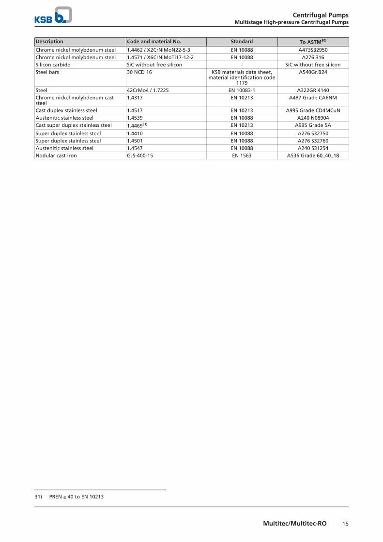
Materials key
Description Code and material No. Standard To ASTM30)
Grey cast iron EN-GJL-250 EN 1561 A48:40BBronze CC480K-GS EN 1982 B505C90250Steel C45+N / 1.0503+N EN 10083-2 A29Gr.1045Steel S355J2H / 1.0576 EN 10210 A618 Grade IIICast steel GP240GH+N / 1.0619+N EN 10213 A216WCBChrome steel 1.4021+QT / X20Cr13+QT EN 10088 A276:420Chrome nickel steel 1.4122 / X35CrMo17 EN 10088 A276S42010Chrome nickel steel 1.4057+QT800 / X17CrNi16-2-
QT800EN 10088 A276:431
Chrome nickel steel 1.4138 / GX120CrMo29-2 SEW 410 -Chrome nickel steel 1.4301 / X5CrNi18-10 EN 10088 A276:304Chrome nickel molybdenum steel 1.4404 / X2CrNiMo 17-12-2 EN 10088 A276:316LChrome nickel molybdenum caststeel
1.4408 / GX5CrNiMo19-11-2 EN 10213 A743CF8M
30) Similar
Centrifugal PumpsMultistage High-pressure Centrifugal Pumps
15Multitec/Multitec-RO
Description Code and material No. Standard To ASTM30)
Chrome nickel molybdenum steel 1.4462 / X2CrNiMoN22-5-3 EN 10088 A473S32950Chrome nickel molybdenum steel 1.4571 / X6CrNiMoTi17-12-2 EN 10088 A276:316Silicon carbide SiC without free silicon - SiC without free siliconSteel bars 30 NCD 16 KSB materials data sheet,
material identification code1179
A540Gr.B24
Steel 42CrMo4 / 1.7225 EN 10083-1 A322GR.4140Chrome nickel molybdenum caststeel
1.4317 EN 10213 A487 Grade CA6NM
Cast duplex stainless steel 1.4517 EN 10213 A995 Grade CD4MCuNAustenitic stainless steel 1.4539 EN 10088 A240 N08904Cast super duplex stainless steel 1.446931) EN 10213 A995 Grade 5A
Super duplex stainless steel 1.4410 EN 10088 A276 S32750Super duplex stainless steel 1.4501 EN 10088 A276 S32760Austenitic stainless steel 1.4547 EN 10088 A240 S31254Nodular cast iron GJS-400-15 EN 1563 A536 Grade 60_40_18
31) PREN ≥ 40 to EN 10213
Centrifugal PumpsMultistage High-pressure Centrifugal Pumps
16 Multitec/Multitec-RO
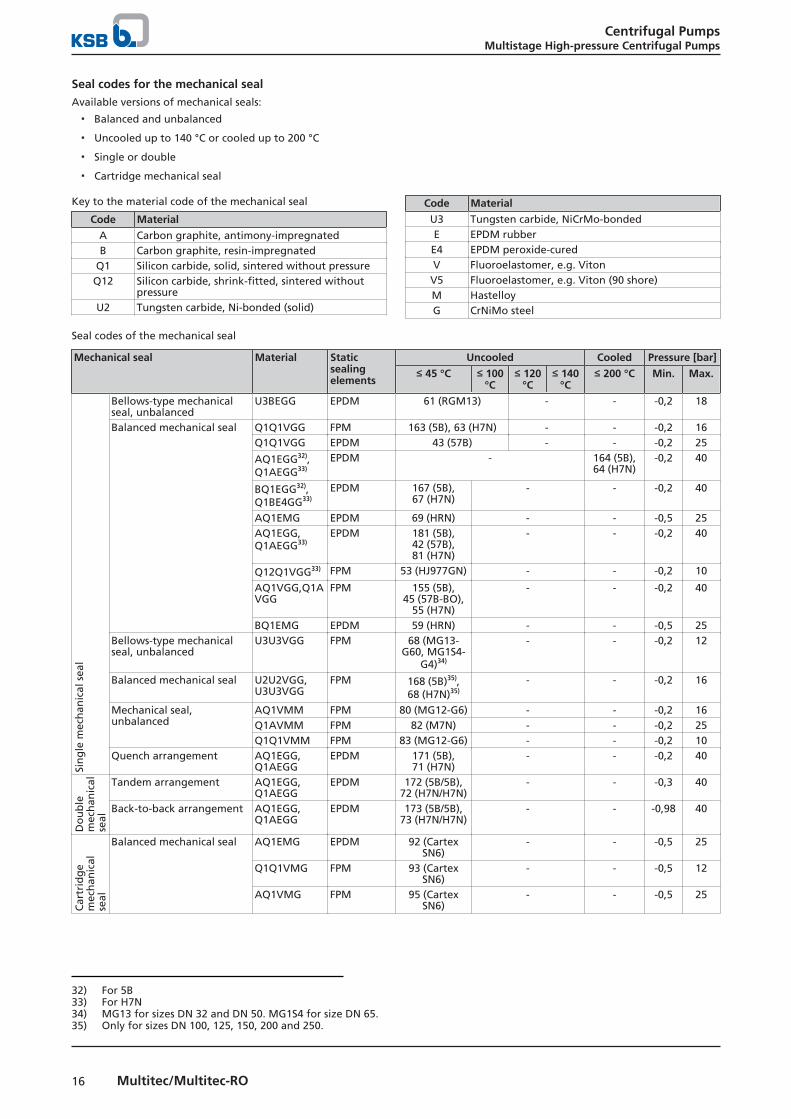
Seal codes for the mechanical sealAvailable versions of mechanical seals:
▪ Balanced and unbalanced
▪ Uncooled up to 140 °C or cooled up to 200 °C
▪ Single or double
▪ Cartridge mechanical seal
Key to the material code of the mechanical seal
Code Material
A Carbon graphite, antimony-impregnatedB Carbon graphite, resin-impregnated
Q1 Silicon carbide, solid, sintered without pressureQ12 Silicon carbide, shrink-fitted, sintered without
pressureU2 Tungsten carbide, Ni-bonded (solid)
Code Material
U3 Tungsten carbide, NiCrMo-bondedE EPDM rubberE4 EPDM peroxide-curedV Fluoroelastomer, e.g. VitonV5 Fluoroelastomer, e.g. Viton (90 shore)M HastelloyG CrNiMo steel
Seal codes of the mechanical seal
Mechanical seal Material Staticsealingelements
Uncooled Cooled Pressure [bar]
≤ 45 °C ≤ 100°C
≤ 120°C
≤ 140°C
≤ 200 °C Min. Max.
Sin
gle
mec
han
ical
sea
l
Bellows-type mechanicalseal, unbalanced
U3BEGG EPDM 61 (RGM13) - - -0,2 18
Balanced mechanical seal Q1Q1VGG FPM 163 (5B), 63 (H7N) - - -0,2 16Q1Q1VGG EPDM 43 (57B) - - -0,2 25
AQ1EGG32),Q1AEGG33)
EPDM - 164 (5B),64 (H7N)
-0,2 40
BQ1EGG32),Q1BE4GG33)
EPDM 167 (5B),67 (H7N)
- - -0,2 40
AQ1EMG EPDM 69 (HRN) - - -0,5 25AQ1EGG,Q1AEGG33)
EPDM 181 (5B),42 (57B),81 (H7N)
- - -0,2 40
Q12Q1VGG33) FPM 53 (HJ977GN) - - -0,2 10
AQ1VGG,Q1AVGG
FPM 155 (5B),45 (57B-BO),
55 (H7N)
- - -0,2 40
BQ1EMG EPDM 59 (HRN) - - -0,5 25Bellows-type mechanicalseal, unbalanced
U3U3VGG FPM 68 (MG13-G60, MG1S4-
G4)34)
- - -0,2 12
Balanced mechanical seal U2U2VGG,U3U3VGG
FPM 168 (5B)35),68 (H7N)35)
- - -0,2 16
Mechanical seal,unbalanced
AQ1VMM FPM 80 (MG12-G6) - - -0,2 16Q1AVMM FPM 82 (M7N) - - -0,2 25Q1Q1VMM FPM 83 (MG12-G6) - - -0,2 10
Quench arrangement AQ1EGG,Q1AEGG
EPDM 171 (5B),71 (H7N)
- - -0,2 40
Do
ub
lem
ech
anic
alse
al
Tandem arrangement AQ1EGG,Q1AEGG
EPDM 172 (5B/5B),72 (H7N/H7N)
- - -0,3 40
Back-to-back arrangement AQ1EGG,Q1AEGG
EPDM 173 (5B/5B),73 (H7N/H7N)
- - -0,98 40
Car
trid
ge
mec
han
ical
seal
Balanced mechanical seal AQ1EMG EPDM 92 (CartexSN6)
- - -0,5 25
Q1Q1VMG FPM 93 (CartexSN6)
- - -0,5 12
AQ1VMG FPM 95 (CartexSN6)
- - -0,5 25
32) For 5B33) For H7N34) MG13 for sizes DN 32 and DN 50. MG1S4 for size DN 65.35) Only for sizes DN 100, 125, 150, 200 and 250.
Centrifugal PumpsMultistage High-pressure Centrifugal Pumps
17Multitec/Multitec-RO
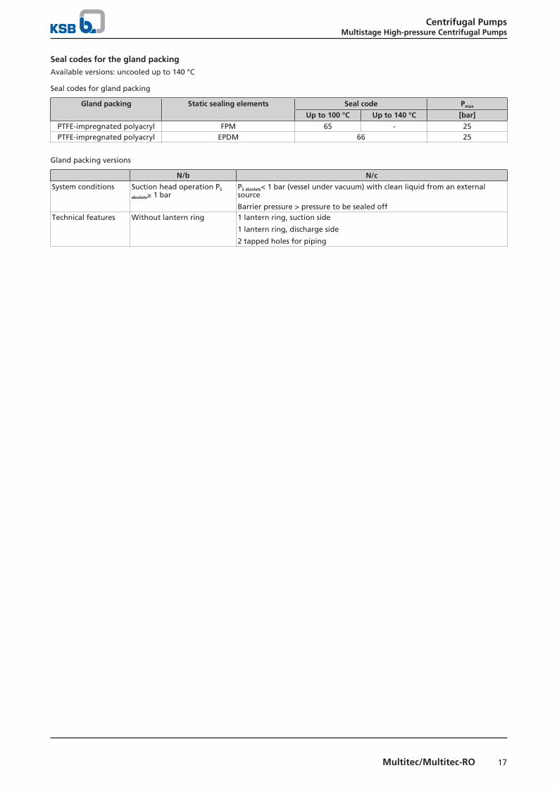
Seal codes for the gland packingAvailable versions: uncooled up to 140 °C
Seal codes for gland packing
Gland packing Static sealing elements Seal code Pmax
Up to 100 °C Up to 140 °C [bar]
PTFE-impregnated polyacryl FPM 65 - 25PTFE-impregnated polyacryl EPDM 66 25
Gland packing versions
N/b N/c
System conditions Suction head operation PS
absolute≥ 1 barPS absolute< 1 bar (vessel under vacuum) with clean liquid from an externalsource
Barrier pressure > pressure to be sealed offTechnical features Without lantern ring 1 lantern ring, suction side
1 lantern ring, discharge side
2 tapped holes for piping

Centrifugal PumpsMultistage High-pressure Centrifugal Pumps
18 Multitec/Multitec-RO
Technical data
Technical data
Size
Shaf
t d
iam
eter
at t
he
cou
plin
g
Bearing Gland packing Shaft protecting sleeve Drive(P/N value)
OtherFi
xed
bea
rin
g
Rad
ial b
eari
ng
Plai
n b
eari
ng
Pack
ing
rin
gd
imen
sio
ns
Lan
tern
rin
g w
idth
Nu
mb
er o
f p
acki
ng
rin
gs
Gla
nd
pac
kin
g
Sin
gle
mec
han
ical
seal
Shaf
t: C
45+
N
Shaf
t 1.
4021
+Q
T
Shaf
t 1.
4462
Shaf
t 1.
4501
Hyd
rau
lic s
yste
m
Max
imu
m im
pel
ler
dia
met
er
Spac
er le
ng
th o
fsp
acer
-typ
e co
up
ling
s
[mm] [mm] [mm] [mm]
32 22 6309 ZZ C3-HT 6309 ZZC3-HT36)
SiC 10 × 10 20 5 45 Ø 35/38 Ø 0,0214 0,0346 0,0302 0,0356 2,1 142 140
50 28 2 × 7309 BUA 6309 ZZC3-HT36)
SiC 10 × 10 20 5 45 Ø 35/38 Ø 0,0523 0,0846 0,0738 0,0869 3,1/4,1
170/ 173
140
65 32 2 × 7309 BUA 6309 ZZC3-HT36)
SiC 10 × 10 20 5 45 Ø 40 Ø 0,0697 0,1128 0,0984 0,1159 5,1/ 6,1
193/ 214
140
100 40 2 × 7312 BUA 6312C3 SiC 12 × 12 25 5 56 Ø 50 Ø 0,15 0,2426 0,2118 0,2495 7,1/ 8,1
241/ 245
180
125 50 2 × 7312 BUA 6312C3 SiC 12 × 12 25 6 66 Ø 60 Ø 0,3016 0,4879 0,4258 0,5016 9,1/ 9,2
301/ 273
180
125 50 2 × 7312 BUA 6312C3 SiC 12 × 12 25 6 66 Ø 60 Ø 0,3016 0,4879 0,4258 0,5016 10,1/ 10,2
305/ 270
180
150 60 2 × 7315 BUA 6315C3 SiC 16 × 16 32 6 78 Ø 70 Ø 0,5371 0,8688 0,7582 0,8930 11,1/ 11,2
378/ 342
200
150 60 2 × 7315 BUA 6315C3 SiC 16 × 16 32 6 78 Ø 70 Ø 0,5371 0,8688 0,7582 0,8930 12,1/ 12,2
382/ 337
200
200 60 2 × 7315 BUA 6315C3 SiC 16 × 16 32 6 78 Ø 70 Ø - 0,8688 - - 13,1/13,2
418/387
200
200 60 2 × 7315 BUA 6315C3 SiC 16 × 16 32 6 78 Ø 70 Ø - 0,8688 - - 14,1/14,2
426/390
200
250 72 2 × 7318 BUA 6318C3 - 16 × 16 32 6 90 Ø 85 Ø - 1,38 - - 15,1/15,2/16,1
477/431
250
Noise characteristics
Surface sound pressure level LpA37)38)
Rated power input PN
[kW]Pump Pump with electric motor
1450 rpm [dB] 2900 rpm [dB] 1450 rpm [dB] 2900 rpm [dB]
2,2 56 57 60 653,0 58 60 62 674,0 59 61 63 685,5 61 63 65 707,5 63 65 66 719 64 66 68 73
11 65 67 68 7315 66 68 70 75
18,5 67 69 71 7622 68 70 72 7730 69 71 73 7837 70 72 74 7945 71 73 75 7955 71 74 75 8075 72 74 77 8290 72 75 77 82110 73 75 78 83132 73 76 78 83160 74 76 79 84200 75 77 80 85250 75 78 80,5 -315 76 78 81 -355 78 80 81 -400 79 81 82 -500 80 82 82 -
36) Applies to grease-lubricated bearings. For oil-lubricated bearings: type 6309C337) Measured at a distance of 1 m from the pump outline (as per DIN 45 635 Parts 1 and 24)38) Increase for 60 Hz operation: 3500 rpm +3 dB; 1750 rpm +1 dB
Centrifugal PumpsMultistage High-pressure Centrifugal Pumps
19Multitec/Multitec-RO
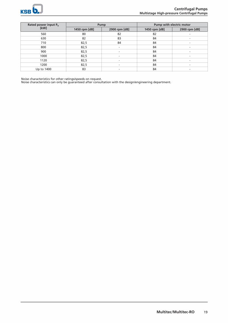
Rated power input PN
[kW]Pump Pump with electric motor
1450 rpm [dB] 2900 rpm [dB] 1450 rpm [dB] 2900 rpm [dB]
560 80 82 82 -630 82 83 84 -710 82,5 84 84 -800 82,5 - 84 -900 82,5 - 84 -
1000 82,5 - 84 -1120 82,5 - 84 -1200 82,5 - 84 -
Up to 1400 83 - 84 -
Noise characteristics for other ratings/speeds on request.Noise characteristics can only be guaranteed after consultation with the design/engineering department.

Centrifugal PumpsMultistage High-pressure Centrifugal Pumps
20 Multitec/Multitec-RO
Selection Charts
Multitec/Multitec-RO, 50 Hz, n = 2900 rpm
H[m]
Q[m³/h]2 3 4 5 10 20 30 40 50 100 200 300 400 500 1000Q[m³/h]
10 20 30 40 50 100 200 300 400 500 1000 2000 3000 4000US.gpm
10 20 30 40 50 100 200 300 400 500 1000 2000 3000IM.gpm
30
40
50
100
200
300
400
500
1000
H[m]
100
200
300
400
500
1000
2000
3000
ft
1 2 3 4 5 10 20 30 40 50 100 200l/s
150-12.2
150-12.1
150-11.2
150-11.1
125-10.2125-9.2
125-10.1125-9.1
100-8.1100-7.165-6.165-5.150-4.150-3.132-2.1

Centrifugal PumpsMultistage High-pressure Centrifugal Pumps
21Multitec/Multitec-RO
Multitec/Multitec-RO, 50 Hz, n = 1450 rpm
H[m]
Q[m³/h]1 2 3 4 5 10 20 30 40 50 100 200 300 400 500 1000 2000Q[m³/h]
5 10 20 30 40 50 100 200 300 400 500 1000 2000 3000 40005000US.gpm
4 5 10 20 30 40 50 100 200 300 400 500 1000 2000 3000 40005000IM.gpm
10
20
30
40
50
100
200
300
400
500
9
H[m]
30
40
50
100
200
300
400
500
1000
ft
0.3 0.4 0.5 1 2 3 4 5 10 20 30 40 50 100 200 300 400 500l/s
32-2.1
50-3.1 50-4.165-5.1
65-6.1
100-7.1100-8.1
125-9.1
125-9.2
125-10.1
125-10.2
150-11.1
150-11.2
150-12.1
150-12.2
200-13.1
200-13.2
200-14.1
200-14.2
250-15.1
250-15.2
250-16.1

Centrifugal PumpsMultistage High-pressure Centrifugal Pumps
22 Multitec/Multitec-RO
Multitec/Multitec-RO, 60 Hz, n = 3500 rpm
H[m]
Q[m³/h]3 4 5 10 20 30 40 50 100 200 300 400 500 1000 1200Q[m³/h]
20 30 40 50 100 200 300 400 500 1000 2000 3000 4000 5000US.gpm
20 30 40 50 100 200 300 400 500 1000 2000 3000 4000IM.gpm
50
100
200
300
400
500
1000
H[m]
200
300
400
500
1000
2000
3000
ft
1 2 3 4 5 10 20 30 40 50 100 200 300l/s
150-12.2
150-11.2
125-10.2
125-10.1
125-9.2
125-9.1100-8.1100-7.165-6.165-5.150-4.150-3.132-2.1
Centrifugal PumpsMultistage High-pressure Centrifugal Pumps
23Multitec/Multitec-RO
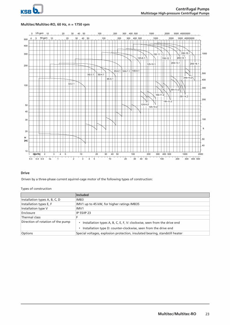
Multitec/Multitec-RO, 60 Hz, n = 1750 rpm
H[m]
Q[m³/h]1 2 3 4 5 10 20 30 40 50 100 200 300 400 500 1000 2000Q[m³/h]
5 10 20 30 40 50 100 200 300 400 500 1000 2000 3000 40005000US.gpm
4 5 10 20 30 40 50 100 200 300 400 500 1000 2000 3000 40005000IM.gpm
10
20
30
40
50
100
200
300
400
500
H[m]
40
50
100
200
300
400
500
1000
ft
0.3 0.4 0.5 1 2 3 4 5 10 20 30 40 50 100 200 300 400 500l/s
32-2.1
50-3.1 50-4.1
65-5.1
65-6.1 100-7.1 100-8.1
125-9.1
125-9.2
125-10.1
125-10.2
150-11.1
150-11.2
150-12.1
150-12.2
200-13.1
200-13.2
200-14.1
200-14.2
250-15.1
250-15.2
250-16.1
Drive
Driven by a three-phase current squirrel-cage motor of the following types of construction:
Types of construction
Included
Installation types A, B, C, D IMB3Installation types E, F IMV1 up to 45 kW, for higher ratings IMB35Installation type V IMV1Enclosure IP 55/IP 23Thermal class FDirection of rotation of the pump ▪ Installation types A, B, C, E, F, V: clockwise, seen from the drive end
▪ Installation type D: counter-clockwise, seen from the drive end
Options Special voltages, explosion protection, insulated bearing, standstill heater
Centrifugal PumpsMultistage High-pressure Centrifugal Pumps
24 Multitec/Multitec-RO
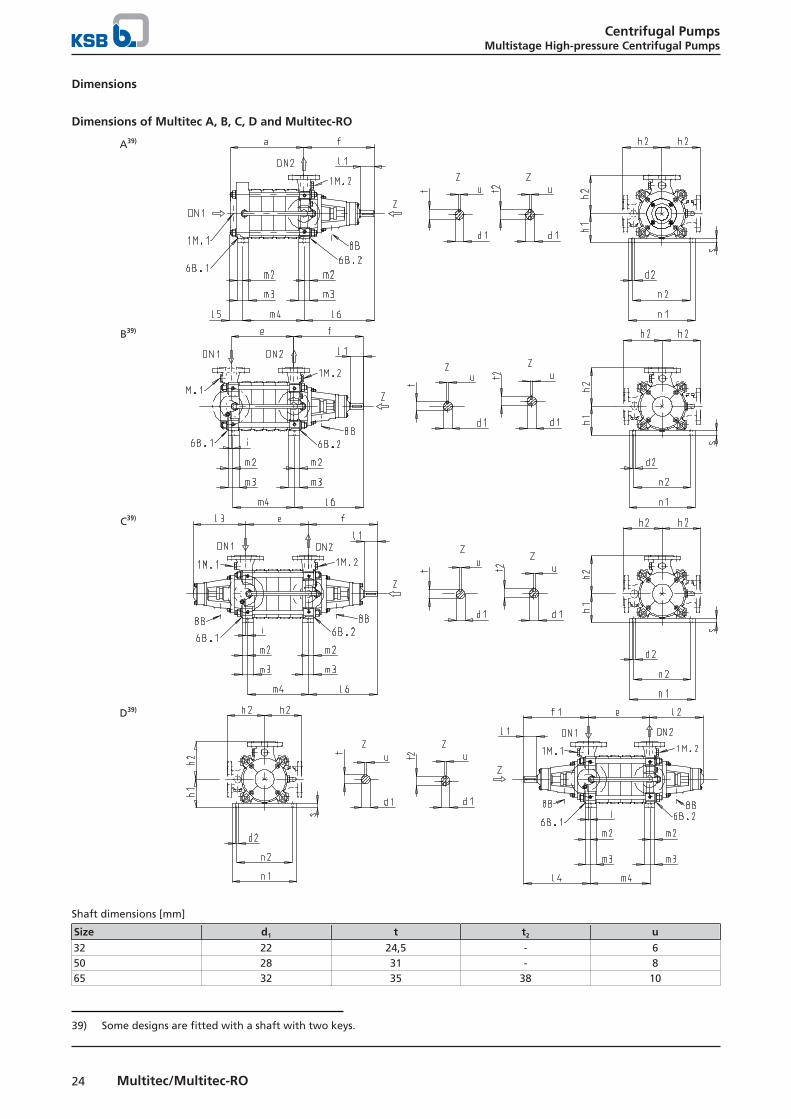
Dimensions
Dimensions of Multitec A, B, C, D and Multitec-RO
A39)
B39)
C39)
D39)
Shaft dimensions [mm]
Size d1 t t2 u
32 22 24,5 - 650 28 31 - 865 32 35 38 10
39) Some designs are fitted with a shaft with two keys.
Centrifugal PumpsMultistage High-pressure Centrifugal Pumps
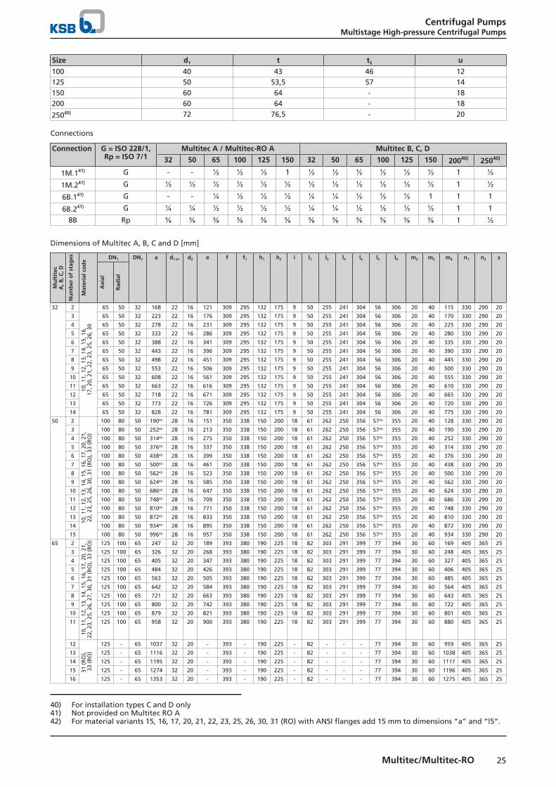
25Multitec/Multitec-RO
Size d1 t t2 u
100 40 43 46 12125 50 53,5 57 14150 60 64 - 18200 60 64 - 18
25040) 72 76,5 - 20
Connections
Connection G = ISO 228/1,Rp = ISO 7/1
Multitec A / Multitec-RO A Multitec B, C, D
32 50 65 100 125 150 32 50 65 100 125 150 20040) 25040)
1M.141) G - - ½ ½ ½ 1 ½ ½ ½ ½ ½ ½ 1 ½1M.241) G ½ ½ ½ ½ ½ ½ ½ ½ ½ ½ ½ ½ 1 ½6B.141) G - - ¼ ½ ½ ½ ¼ ¼ ½ ½ ½ 1 1 1
6B.241) G ¼ ¼ ½ ½ ½ ½ ¼ ¼ ½ ½ ½ ½ 1 1
8B Rp ⅜ ⅜ ⅜ ⅜ ⅜ ⅜ ⅜ ⅜ ⅜ ⅜ ⅜ ⅜ 1 ½
Dimensions of Multitec A, B, C and D [mm]
Mu
ltit
ecA
, B, C
, D
Nu
mb
er o
f st
ages
Mat
eria
l co
de
DN1 DN2 a d1 k7 d2 e f f1 h1 h2 i l1 l2 l3 l4 l5 l6 m2 m3 m4 n1 n2 s
Axi
al
Rad
ial
32 2
10, 1
1, 1
2, 1
3, 1
4, 1
5, 1
6,17
, 20,
21,
22,
23,
25,
26,
30
65 50 32 168 22 16 121 309 295 132 175 9 50 255 241 304 56 306 20 40 115 330 290 20
3 65 50 32 223 22 16 176 309 295 132 175 9 50 255 241 304 56 306 20 40 170 330 290 20
4 65 50 32 278 22 16 231 309 295 132 175 9 50 255 241 304 56 306 20 40 225 330 290 20
5 65 50 32 333 22 16 286 309 295 132 175 9 50 255 241 304 56 306 20 40 280 330 290 20
6 65 50 32 388 22 16 341 309 295 132 175 9 50 255 241 304 56 306 20 40 335 330 290 20
7 65 50 32 443 22 16 396 309 295 132 175 9 50 255 241 304 56 306 20 40 390 330 290 20
8 65 50 32 498 22 16 451 309 295 132 175 9 50 255 241 304 56 306 20 40 445 330 290 20
9 65 50 32 553 22 16 506 309 295 132 175 9 50 255 241 304 56 306 20 40 500 330 290 20
10 65 50 32 608 22 16 561 309 295 132 175 9 50 255 241 304 56 306 20 40 555 330 290 20
11 65 50 32 663 22 16 616 309 295 132 175 9 50 255 241 304 56 306 20 40 610 330 290 20
12 65 50 32 718 22 16 671 309 295 132 175 9 50 255 241 304 56 306 20 40 665 330 290 20
13 65 50 32 773 22 16 726 309 295 132 175 9 50 255 241 304 56 306 20 40 720 330 290 20
14 65 50 32 828 22 16 781 309 295 132 175 9 50 255 241 304 56 306 20 40 775 330 290 20
50 2
10, 1
1, 1
2, 1
3, 1
4, 1
5, 1
6, 1
7, 2
0, 2
1,22
, 23,
25,
26,
30,
31
(RO
), 3
3 (R
O)
100 80 50 19042) 28 16 151 350 338 150 200 18 61 262 250 356 5742) 355 20 40 128 330 290 20
3 100 80 50 25242) 28 16 213 350 338 150 200 18 61 262 250 356 5742) 355 20 40 190 330 290 20
4 100 80 50 31442) 28 16 275 350 338 150 200 18 61 262 250 356 5742) 355 20 40 252 330 290 20
5 100 80 50 37642) 28 16 337 350 338 150 200 18 61 262 250 356 5742) 355 20 40 314 330 290 20
6 100 80 50 43842) 28 16 399 350 338 150 200 18 61 262 250 356 5742) 355 20 40 376 330 290 20
7 100 80 50 50042) 28 16 461 350 338 150 200 18 61 262 250 356 5742) 355 20 40 438 330 290 20
8 100 80 50 56242) 28 16 523 350 338 150 200 18 61 262 250 356 5742) 355 20 40 500 330 290 20
9 100 80 50 62442) 28 16 585 350 338 150 200 18 61 262 250 356 5742) 355 20 40 562 330 290 20
10 100 80 50 68642) 28 16 647 350 338 150 200 18 61 262 250 356 5742) 355 20 40 624 330 290 20
11 100 80 50 74842) 28 16 709 350 338 150 200 18 61 262 250 356 5742) 355 20 40 686 330 290 20
12 100 80 50 81042) 28 16 771 350 338 150 200 18 61 262 250 356 5742) 355 20 40 748 330 290 20
13 100 80 50 87242) 28 16 833 350 338 150 200 18 61 262 250 356 5742) 355 20 40 810 330 290 20
14 100 80 50 93442) 28 16 895 350 338 150 200 18 61 262 250 356 5742) 355 20 40 872 330 290 20
15 100 80 50 99642) 28 16 957 350 338 150 200 18 61 262 250 356 5742) 355 20 40 934 330 290 20
65 2
10, 1
1, 1
2, 1
3, 1
4, 1
5, 1
6, 1
7, 2
0, 2
1,22
, 23,
25,
26,
27,
30,
31
(RO
), 3
3 (R
O) 125 100 65 247 32 20 189 393 380 190 225 18 82 303 291 399 77 394 30 60 169 405 365 25
3 125 100 65 326 32 20 268 393 380 190 225 18 82 303 291 399 77 394 30 60 248 405 365 25
4 125 100 65 405 32 20 347 393 380 190 225 18 82 303 291 399 77 394 30 60 327 405 365 25
5 125 100 65 484 32 20 426 393 380 190 225 18 82 303 291 399 77 394 30 60 406 405 365 25
6 125 100 65 563 32 20 505 393 380 190 225 18 82 303 291 399 77 394 30 60 485 405 365 25
7 125 100 65 642 32 20 584 393 380 190 225 18 82 303 291 399 77 394 30 60 564 405 365 25
8 125 100 65 721 32 20 663 393 380 190 225 18 82 303 291 399 77 394 30 60 643 405 365 25
9 125 100 65 800 32 20 742 393 380 190 225 18 82 303 291 399 77 394 30 60 722 405 365 25
10 125 100 65 879 32 20 821 393 380 190 225 18 82 303 291 399 77 394 30 60 801 405 365 25
11 125 100 65 958 32 20 900 393 380 190 225 18 82 303 291 399 77 394 30 60 880 405 365 25
12
31 (
RO
),
33 (
RO
)
125 - 65 1037 32 20 - 393 - 190 225 - 82 - - - 77 394 30 60 959 405 365 25
13 125 - 65 1116 32 20 - 393 - 190 225 - 82 - - - 77 394 30 60 1038 405 365 25
14 125 - 65 1195 32 20 - 393 - 190 225 - 82 - - - 77 394 30 60 1117 405 365 25
15 125 - 65 1274 32 20 - 393 - 190 225 - 82 - - - 77 394 30 60 1196 405 365 25
16 125 - 65 1353 32 20 - 393 - 190 225 - 82 - - - 77 394 30 60 1275 405 365 25
40) For installation types C and D only41) Not provided on Multitec RO A42) For material variants 15, 16, 17, 20, 21, 22, 23, 25, 26, 30, 31 (RO) with ANSI flanges add 15 mm to dimensions “a” and “l5”.
Centrifugal PumpsMultistage High-pressure Centrifugal Pumps
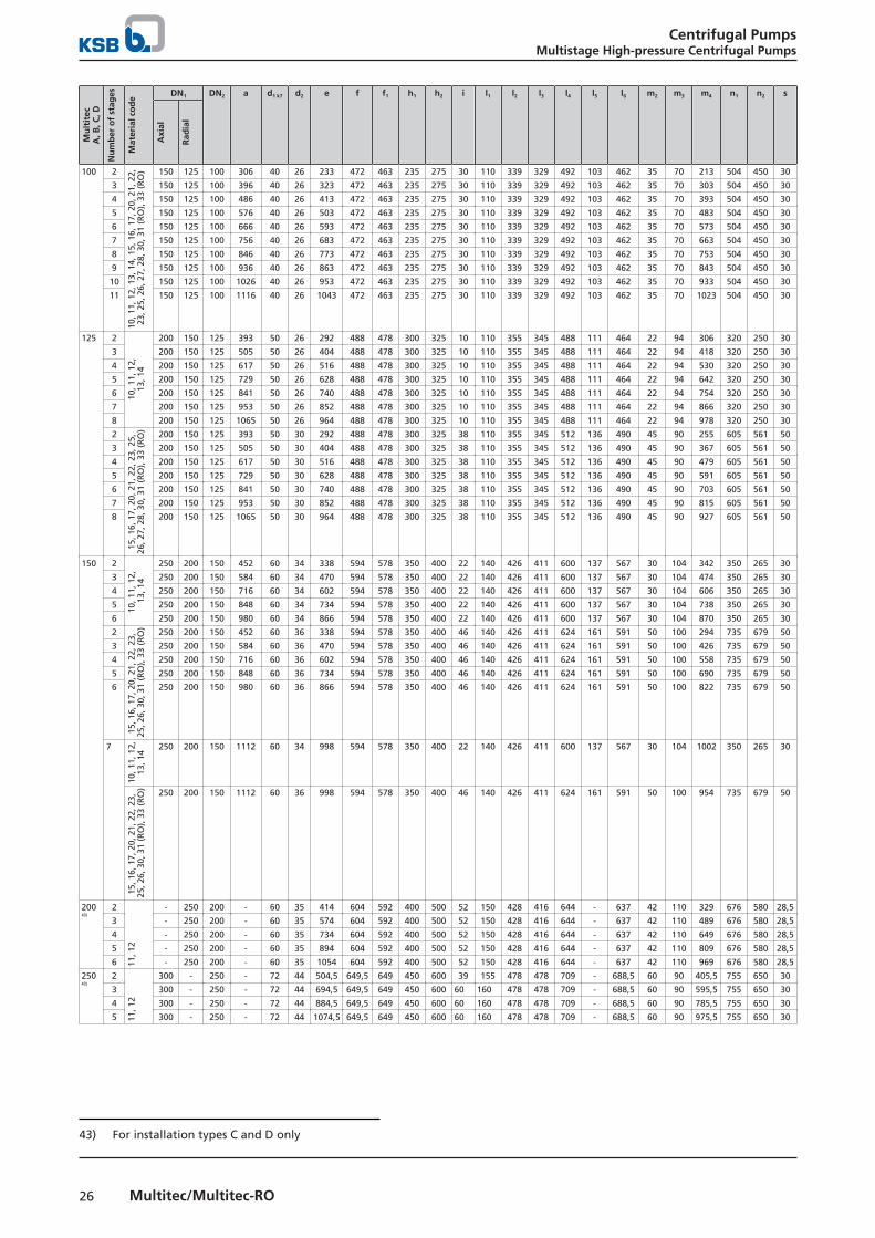
26 Multitec/Multitec-RO
Mu
ltit
ecA
, B, C
, D
Nu
mb
er o
f st
ages
Mat
eria
l co
de
DN1 DN2 a d1 k7 d2 e f f1 h1 h2 i l1 l2 l3 l4 l5 l6 m2 m3 m4 n1 n2 s
Axi
al
Rad
ial
100 2
10, 1
1, 1
2, 1
3, 1
4, 1
5, 1
6, 1
7, 2
0, 2
1, 2
2,
23, 2
5, 2
6, 2
7, 2
8, 3
0, 3
1 (R
O),
33
(RO
) 150 125 100 306 40 26 233 472 463 235 275 30 110 339 329 492 103 462 35 70 213 504 450 30
3 150 125 100 396 40 26 323 472 463 235 275 30 110 339 329 492 103 462 35 70 303 504 450 30
4 150 125 100 486 40 26 413 472 463 235 275 30 110 339 329 492 103 462 35 70 393 504 450 30
5 150 125 100 576 40 26 503 472 463 235 275 30 110 339 329 492 103 462 35 70 483 504 450 30
6 150 125 100 666 40 26 593 472 463 235 275 30 110 339 329 492 103 462 35 70 573 504 450 30
7 150 125 100 756 40 26 683 472 463 235 275 30 110 339 329 492 103 462 35 70 663 504 450 30
8 150 125 100 846 40 26 773 472 463 235 275 30 110 339 329 492 103 462 35 70 753 504 450 30
9 150 125 100 936 40 26 863 472 463 235 275 30 110 339 329 492 103 462 35 70 843 504 450 30
10 150 125 100 1026 40 26 953 472 463 235 275 30 110 339 329 492 103 462 35 70 933 504 450 30
11 150 125 100 1116 40 26 1043 472 463 235 275 30 110 339 329 492 103 462 35 70 1023 504 450 30
125 2
10, 1
1, 1
2,13
, 14
200 150 125 393 50 26 292 488 478 300 325 10 110 355 345 488 111 464 22 94 306 320 250 30
3 200 150 125 505 50 26 404 488 478 300 325 10 110 355 345 488 111 464 22 94 418 320 250 30
4 200 150 125 617 50 26 516 488 478 300 325 10 110 355 345 488 111 464 22 94 530 320 250 30
5 200 150 125 729 50 26 628 488 478 300 325 10 110 355 345 488 111 464 22 94 642 320 250 30
6 200 150 125 841 50 26 740 488 478 300 325 10 110 355 345 488 111 464 22 94 754 320 250 30
7 200 150 125 953 50 26 852 488 478 300 325 10 110 355 345 488 111 464 22 94 866 320 250 30
8 200 150 125 1065 50 26 964 488 478 300 325 10 110 355 345 488 111 464 22 94 978 320 250 30
2
15, 1
6, 1
7, 2
0, 2
1, 2
2, 2
3, 2
5,26
, 27,
28,
30,
31
(RO
), 3
3 (R
O) 200 150 125 393 50 30 292 488 478 300 325 38 110 355 345 512 136 490 45 90 255 605 561 50
3 200 150 125 505 50 30 404 488 478 300 325 38 110 355 345 512 136 490 45 90 367 605 561 50
4 200 150 125 617 50 30 516 488 478 300 325 38 110 355 345 512 136 490 45 90 479 605 561 50
5 200 150 125 729 50 30 628 488 478 300 325 38 110 355 345 512 136 490 45 90 591 605 561 50
6 200 150 125 841 50 30 740 488 478 300 325 38 110 355 345 512 136 490 45 90 703 605 561 50
7 200 150 125 953 50 30 852 488 478 300 325 38 110 355 345 512 136 490 45 90 815 605 561 50
8 200 150 125 1065 50 30 964 488 478 300 325 38 110 355 345 512 136 490 45 90 927 605 561 50
150 2
10, 1
1, 1
2,
13, 1
4
250 200 150 452 60 34 338 594 578 350 400 22 140 426 411 600 137 567 30 104 342 350 265 30
3 250 200 150 584 60 34 470 594 578 350 400 22 140 426 411 600 137 567 30 104 474 350 265 30
4 250 200 150 716 60 34 602 594 578 350 400 22 140 426 411 600 137 567 30 104 606 350 265 30
5 250 200 150 848 60 34 734 594 578 350 400 22 140 426 411 600 137 567 30 104 738 350 265 30
6 250 200 150 980 60 34 866 594 578 350 400 22 140 426 411 600 137 567 30 104 870 350 265 30
2
15, 1
6, 1
7, 2
0, 2
1, 2
2, 2
3,
25, 2
6, 3
0, 3
1 (R
O),
33
(RO
) 250 200 150 452 60 36 338 594 578 350 400 46 140 426 411 624 161 591 50 100 294 735 679 50
3 250 200 150 584 60 36 470 594 578 350 400 46 140 426 411 624 161 591 50 100 426 735 679 50
4 250 200 150 716 60 36 602 594 578 350 400 46 140 426 411 624 161 591 50 100 558 735 679 50
5 250 200 150 848 60 36 734 594 578 350 400 46 140 426 411 624 161 591 50 100 690 735 679 50
6 250 200 150 980 60 36 866 594 578 350 400 46 140 426 411 624 161 591 50 100 822 735 679 50
7
10, 1
1, 1
2,13
, 14
250 200 150 1112 60 34 998 594 578 350 400 22 140 426 411 600 137 567 30 104 1002 350 265 30
15, 1
6, 1
7, 2
0, 2
1, 2
2, 2
3,
25, 2
6, 3
0, 3
1 (R
O),
33
(RO
) 250 200 150 1112 60 36 998 594 578 350 400 46 140 426 411 624 161 591 50 100 954 735 679 50
20043)
2
11, 1
2
- 250 200 - 60 35 414 604 592 400 500 52 150 428 416 644 - 637 42 110 329 676 580 28,5
3 - 250 200 - 60 35 574 604 592 400 500 52 150 428 416 644 - 637 42 110 489 676 580 28,5
4 - 250 200 - 60 35 734 604 592 400 500 52 150 428 416 644 - 637 42 110 649 676 580 28,5
5 - 250 200 - 60 35 894 604 592 400 500 52 150 428 416 644 - 637 42 110 809 676 580 28,5
6 - 250 200 - 60 35 1054 604 592 400 500 52 150 428 416 644 - 637 42 110 969 676 580 28,5
25043)
2
11, 1
2
300 - 250 - 72 44 504,5 649,5 649 450 600 39 155 478 478 709 - 688,5 60 90 405,5 755 650 30
3 300 - 250 - 72 44 694,5 649,5 649 450 600 60 160 478 478 709 - 688,5 60 90 595,5 755 650 30
4 300 - 250 - 72 44 884,5 649,5 649 450 600 60 160 478 478 709 - 688,5 60 90 785,5 755 650 30
5 300 - 250 - 72 44 1074,5 649,5 649 450 600 60 160 478 478 709 - 688,5 60 90 975,5 755 650 30
43) For installation types C and D only
Centrifugal PumpsMultistage High-pressure Centrifugal Pumps
27Multitec/Multitec-RO
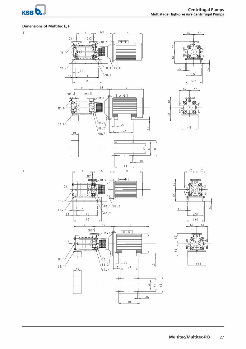
Dimensions of Multitec E, F
E
F
Centrifugal PumpsMultistage High-pressure Centrifugal Pumps
28 Multitec/Multitec-RO
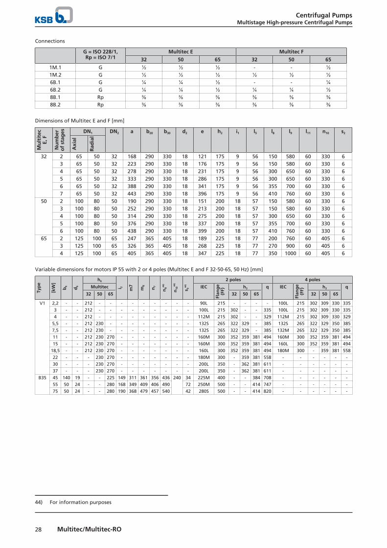
Connections
G = ISO 228/1,Rp = ISO 7/1
Multitec E Multitec F
32 50 65 32 50 65
1M.1 G ½ ½ ½ - - ½1M.2 G ½ ½ ½ ½ ½ ½6B.1 G ¼ ¼ ½ - - ¼6B.2 G ¼ ¼ ½ ¼ ¼ ½8B.1 Rp ⅜ ⅜ ⅜ ⅜ ⅜ ⅜8B.2 Rp ⅜ ⅜ ⅜ ⅜ ⅜ ⅜
Dimensions of Multitec E and F [mm]
Mu
ltit
ecE,
F
Nu
mb
ero
f st
ages DN1 DN2 a b20 b30 d2 e h2 i1 l5 l8 l9 l11 n10 s2
Axi
al
Rad
ial
32 2 65 50 32 168 290 330 18 121 175 9 56 150 580 60 330 63 65 50 32 223 290 330 18 176 175 9 56 150 580 60 330 64 65 50 32 278 290 330 18 231 175 9 56 300 650 60 330 65 65 50 32 333 290 330 18 286 175 9 56 300 650 60 330 66 65 50 32 388 290 330 18 341 175 9 56 355 700 60 330 67 65 50 32 443 290 330 18 396 175 9 56 410 760 60 330 6
50 2 100 80 50 190 290 330 18 151 200 18 57 150 580 60 330 63 100 80 50 252 290 330 18 213 200 18 57 150 580 60 330 64 100 80 50 314 290 330 18 275 200 18 57 300 650 60 330 65 100 80 50 376 290 330 18 337 200 18 57 355 700 60 330 66 100 80 50 438 290 330 18 399 200 18 57 410 760 60 330 6
65 2 125 100 65 247 365 405 18 189 225 18 77 200 760 60 405 63 125 100 65 326 365 405 18 268 225 18 77 270 900 60 405 64 125 100 65 405 365 405 18 347 225 18 77 350 1000 60 405 6
Variable dimensions for motors IP 55 with 2 or 4 poles (Multitec E and F 32-50-65, 50 Hz) [mm]
Typ
e
[kW
]
b6
d6
h6
i 2 m7
m8
n7
n844
)
n10
44)
s 344
)
2 poles 4 poles
Multitec IEC
Flan
ge
(FF)
h3 q IEC
Flan
ge
(FF)
h3 q
32 50 65 32 50 65 32 50 65
V1 2,2 - - 212 - - - - - - - - - 90L 215 - - - - 100L 215 302 309 330 335
3 - - 212 - - - - - - - - - 100L 215 302 - - 335 100L 215 302 309 330 335
4 - - 212 - - - - - - - - - 112M 215 302 - - 329 112M 215 302 309 330 329
5,5 - - 212 230 - - - - - - - - 132S 265 322 329 - 385 132S 265 322 329 350 385
7,5 - - 212 230 - - - - - - - - 132S 265 322 329 - 385 132M 265 322 329 350 385
11 - - 212 230 270 - - - - - - - 160M 300 352 359 381 494 160M 300 352 359 381 494
15 - - 212 230 270 - - - - - - - 160M 300 352 359 381 494 160L 300 352 359 381 494
18,5 - - 212 230 270 - - - - - - - 160L 300 352 359 381 494 180M 300 - 359 381 558
22 - - - 230 270 - - - - - - - 180M 300 - 359 381 558 - - - - - -
30 - - - 230 270 - - - - - - - 200L 350 - 362 381 611 - - - - - -
37 - - - 230 270 - - - - - - - 200L 350 - 362 381 611 - - - - - -
B35 45 140 19 - - 225 149 311 361 356 436 240 34 225M 400 - - 384 708 - - - - - -
55 50 24 - - 280 168 349 409 406 490 72 250M 500 - - 414 747 - - - - - -
75 50 24 - - 280 190 368 479 457 540 42 280S 500 - - 414 820 - - - - - -
44) For information purposes
Centrifugal PumpsMultistage High-pressure Centrifugal Pumps
29Multitec/Multitec-RO
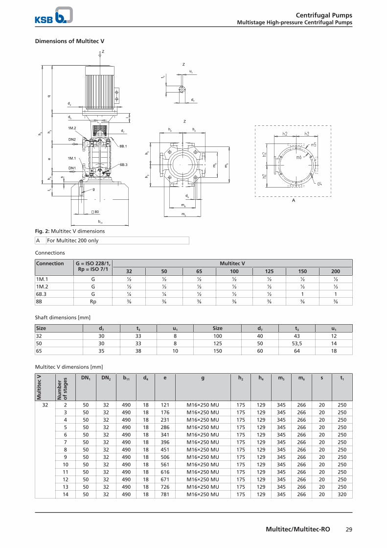
Dimensions of Multitec V
d7
h2 h2
t 3
h 2h 2
m5
m6
m5
m6
d4
t 1
h 5 h 3h 4
b11
80
g
d7
d5
d3
eq
Z
A
u1
Z
Z
8B.1
6B.3DN1
DN2
1M.1
1M.2
s
l
Fig. 2: Multitec V dimensions
A For Multitec 200 only
Connections
Connection G = ISO 228/1,Rp = ISO 7/1
Multitec V
32 50 65 100 125 150 200
1M.1 G ½ ½ ½ ½ ½ ½ ½1M.2 G ½ ½ ½ ½ ½ ½ ½6B.3 G ¼ ¼ ½ ½ ½ 1 18B Rp ⅜ ⅜ ⅜ ⅜ ⅜ ⅜ ⅜
Shaft dimensions [mm]
Size d7 t3 u1 Size d7 t3 u1
32 30 33 8 100 40 43 1250 30 33 8 125 50 53,5 1465 35 38 10 150 60 64 18
Multitec V dimensions [mm]
Mu
ltit
ec V
Nu
mb
ero
f st
ages
DN1 DN2 b11 d4 e g h2 h4 m5 m6 s t1
32 2 50 32 490 18 121 M16×250 MU 175 129 345 266 20 2503 50 32 490 18 176 M16×250 MU 175 129 345 266 20 2504 50 32 490 18 231 M16×250 MU 175 129 345 266 20 2505 50 32 490 18 286 M16×250 MU 175 129 345 266 20 2506 50 32 490 18 341 M16×250 MU 175 129 345 266 20 2507 50 32 490 18 396 M16×250 MU 175 129 345 266 20 2508 50 32 490 18 451 M16×250 MU 175 129 345 266 20 2509 50 32 490 18 506 M16×250 MU 175 129 345 266 20 25010 50 32 490 18 561 M16×250 MU 175 129 345 266 20 25011 50 32 490 18 616 M16×250 MU 175 129 345 266 20 25012 50 32 490 18 671 M16×250 MU 175 129 345 266 20 25013 50 32 490 18 726 M16×250 MU 175 129 345 266 20 25014 50 32 490 18 781 M16×250 MU 175 129 345 266 20 320
Centrifugal PumpsMultistage High-pressure Centrifugal Pumps
30 Multitec/Multitec-RO
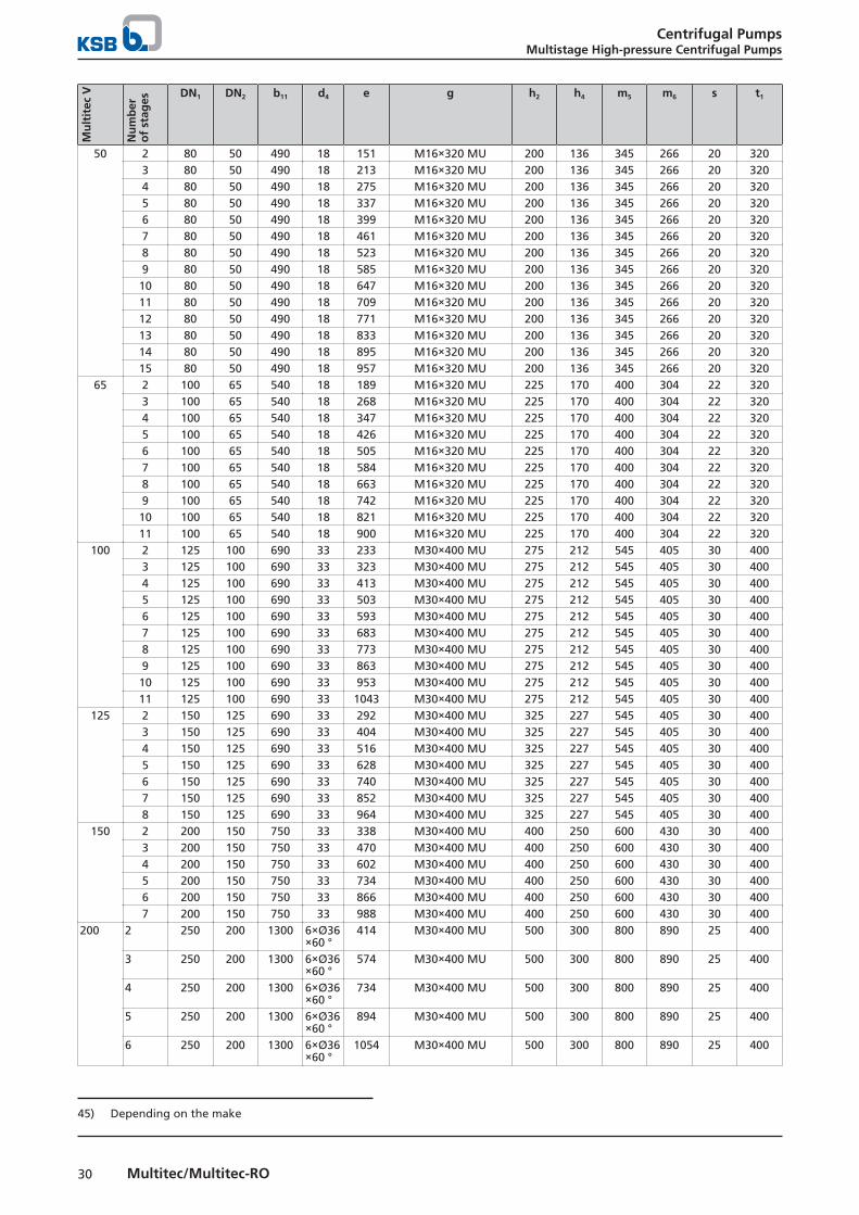
Mu
ltit
ec V
Nu
mb
ero
f st
ages
DN1 DN2 b11 d4 e g h2 h4 m5 m6 s t1
50 2 80 50 490 18 151 M16×320 MU 200 136 345 266 20 3203 80 50 490 18 213 M16×320 MU 200 136 345 266 20 3204 80 50 490 18 275 M16×320 MU 200 136 345 266 20 3205 80 50 490 18 337 M16×320 MU 200 136 345 266 20 3206 80 50 490 18 399 M16×320 MU 200 136 345 266 20 3207 80 50 490 18 461 M16×320 MU 200 136 345 266 20 3208 80 50 490 18 523 M16×320 MU 200 136 345 266 20 3209 80 50 490 18 585 M16×320 MU 200 136 345 266 20 32010 80 50 490 18 647 M16×320 MU 200 136 345 266 20 32011 80 50 490 18 709 M16×320 MU 200 136 345 266 20 32012 80 50 490 18 771 M16×320 MU 200 136 345 266 20 32013 80 50 490 18 833 M16×320 MU 200 136 345 266 20 32014 80 50 490 18 895 M16×320 MU 200 136 345 266 20 32015 80 50 490 18 957 M16×320 MU 200 136 345 266 20 320
65 2 100 65 540 18 189 M16×320 MU 225 170 400 304 22 3203 100 65 540 18 268 M16×320 MU 225 170 400 304 22 3204 100 65 540 18 347 M16×320 MU 225 170 400 304 22 3205 100 65 540 18 426 M16×320 MU 225 170 400 304 22 3206 100 65 540 18 505 M16×320 MU 225 170 400 304 22 3207 100 65 540 18 584 M16×320 MU 225 170 400 304 22 3208 100 65 540 18 663 M16×320 MU 225 170 400 304 22 3209 100 65 540 18 742 M16×320 MU 225 170 400 304 22 32010 100 65 540 18 821 M16×320 MU 225 170 400 304 22 32011 100 65 540 18 900 M16×320 MU 225 170 400 304 22 320
100 2 125 100 690 33 233 M30×400 MU 275 212 545 405 30 4003 125 100 690 33 323 M30×400 MU 275 212 545 405 30 4004 125 100 690 33 413 M30×400 MU 275 212 545 405 30 4005 125 100 690 33 503 M30×400 MU 275 212 545 405 30 4006 125 100 690 33 593 M30×400 MU 275 212 545 405 30 4007 125 100 690 33 683 M30×400 MU 275 212 545 405 30 4008 125 100 690 33 773 M30×400 MU 275 212 545 405 30 4009 125 100 690 33 863 M30×400 MU 275 212 545 405 30 40010 125 100 690 33 953 M30×400 MU 275 212 545 405 30 40011 125 100 690 33 1043 M30×400 MU 275 212 545 405 30 400
125 2 150 125 690 33 292 M30×400 MU 325 227 545 405 30 4003 150 125 690 33 404 M30×400 MU 325 227 545 405 30 4004 150 125 690 33 516 M30×400 MU 325 227 545 405 30 4005 150 125 690 33 628 M30×400 MU 325 227 545 405 30 4006 150 125 690 33 740 M30×400 MU 325 227 545 405 30 4007 150 125 690 33 852 M30×400 MU 325 227 545 405 30 4008 150 125 690 33 964 M30×400 MU 325 227 545 405 30 400
150 2 200 150 750 33 338 M30×400 MU 400 250 600 430 30 4003 200 150 750 33 470 M30×400 MU 400 250 600 430 30 4004 200 150 750 33 602 M30×400 MU 400 250 600 430 30 4005 200 150 750 33 734 M30×400 MU 400 250 600 430 30 4006 200 150 750 33 866 M30×400 MU 400 250 600 430 30 4007 200 150 750 33 988 M30×400 MU 400 250 600 430 30 400
200 2 250 200 1300 6×Ø36×60 °
414 M30×400 MU 500 300 800 890 25 400
3 250 200 1300 6×Ø36×60 °
574 M30×400 MU 500 300 800 890 25 400
4 250 200 1300 6×Ø36×60 °
734 M30×400 MU 500 300 800 890 25 400
5 250 200 1300 6×Ø36×60 °
894 M30×400 MU 500 300 800 890 25 400
6 250 200 1300 6×Ø36×60 °
1054 M30×400 MU 500 300 800 890 25 400
45) Depending on the make
Centrifugal PumpsMultistage High-pressure Centrifugal Pumps
31Multitec/Multitec-RO
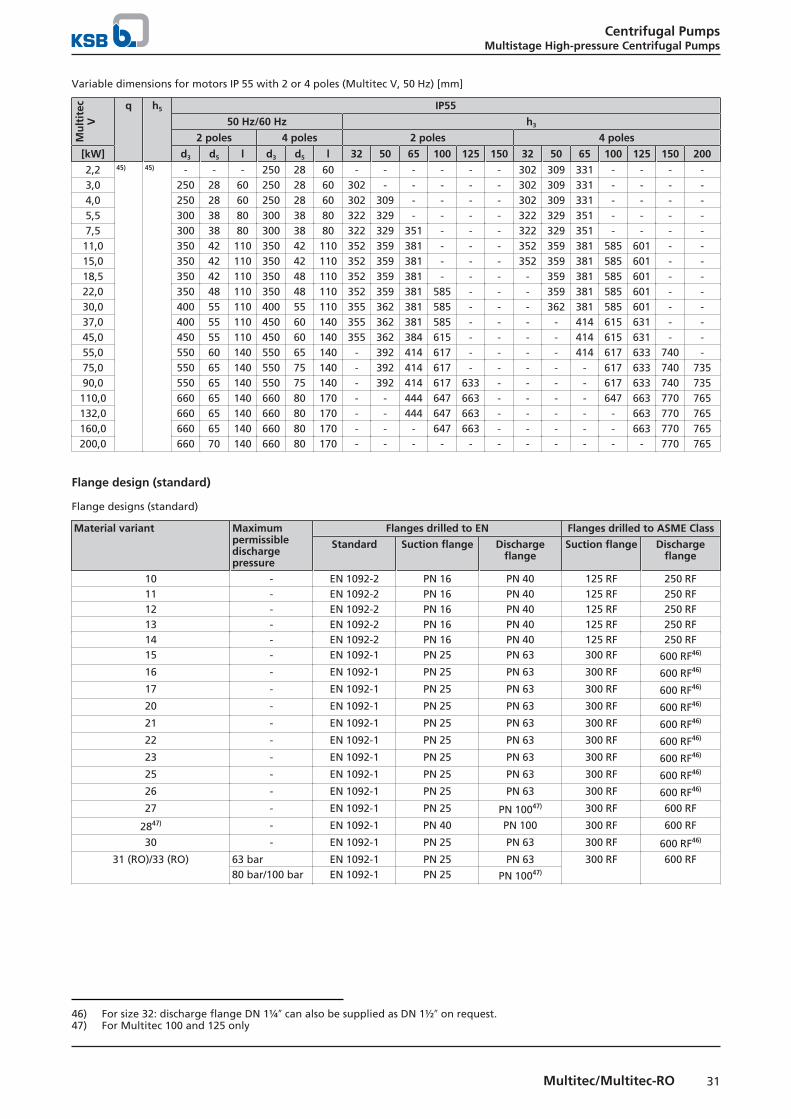
Variable dimensions for motors IP 55 with 2 or 4 poles (Multitec V, 50 Hz) [mm]M
ult
itec
V
q h5 IP55
50 Hz/60 Hz h3
2 poles 4 poles 2 poles 4 poles
[kW] d3 d5 l d3 d5 l 32 50 65 100 125 150 32 50 65 100 125 150 200
2,2 45) 45) - - - 250 28 60 - - - - - - 302 309 331 - - - -3,0 250 28 60 250 28 60 302 - - - - - 302 309 331 - - - -4,0 250 28 60 250 28 60 302 309 - - - - 302 309 331 - - - -5,5 300 38 80 300 38 80 322 329 - - - - 322 329 351 - - - -7,5 300 38 80 300 38 80 322 329 351 - - - 322 329 351 - - - -11,0 350 42 110 350 42 110 352 359 381 - - - 352 359 381 585 601 - -15,0 350 42 110 350 42 110 352 359 381 - - - 352 359 381 585 601 - -18,5 350 42 110 350 48 110 352 359 381 - - - - 359 381 585 601 - -22,0 350 48 110 350 48 110 352 359 381 585 - - - 359 381 585 601 - -30,0 400 55 110 400 55 110 355 362 381 585 - - - 362 381 585 601 - -37,0 400 55 110 450 60 140 355 362 381 585 - - - - 414 615 631 - -45,0 450 55 110 450 60 140 355 362 384 615 - - - - 414 615 631 - -55,0 550 60 140 550 65 140 - 392 414 617 - - - - 414 617 633 740 -75,0 550 65 140 550 75 140 - 392 414 617 - - - - - 617 633 740 73590,0 550 65 140 550 75 140 - 392 414 617 633 - - - - 617 633 740 735110,0 660 65 140 660 80 170 - - 444 647 663 - - - - 647 663 770 765132,0 660 65 140 660 80 170 - - 444 647 663 - - - - - 663 770 765160,0 660 65 140 660 80 170 - - - 647 663 - - - - - 663 770 765200,0 660 70 140 660 80 170 - - - - - - - - - - - 770 765
Flange design (standard)
Flange designs (standard)
Material variant Maximumpermissibledischargepressure
Flanges drilled to EN Flanges drilled to ASME Class
Standard Suction flange Dischargeflange
Suction flange Dischargeflange
10 - EN 1092-2 PN 16 PN 40 125 RF 250 RF11 - EN 1092-2 PN 16 PN 40 125 RF 250 RF12 - EN 1092-2 PN 16 PN 40 125 RF 250 RF13 - EN 1092-2 PN 16 PN 40 125 RF 250 RF14 - EN 1092-2 PN 16 PN 40 125 RF 250 RF15 - EN 1092-1 PN 25 PN 63 300 RF 600 RF46)
16 - EN 1092-1 PN 25 PN 63 300 RF 600 RF46)
17 - EN 1092-1 PN 25 PN 63 300 RF 600 RF46)
20 - EN 1092-1 PN 25 PN 63 300 RF 600 RF46)
21 - EN 1092-1 PN 25 PN 63 300 RF 600 RF46)
22 - EN 1092-1 PN 25 PN 63 300 RF 600 RF46)
23 - EN 1092-1 PN 25 PN 63 300 RF 600 RF46)
25 - EN 1092-1 PN 25 PN 63 300 RF 600 RF46)
26 - EN 1092-1 PN 25 PN 63 300 RF 600 RF46)
27 - EN 1092-1 PN 25 PN 10047) 300 RF 600 RF
2847) - EN 1092-1 PN 40 PN 100 300 RF 600 RF
30 - EN 1092-1 PN 25 PN 63 300 RF 600 RF46)
31 (RO)/33 (RO) 63 bar EN 1092-1 PN 25 PN 63 300 RF 600 RF80 bar/100 bar EN 1092-1 PN 25 PN 10047)
46) For size 32: discharge flange DN 1¼″ can also be supplied as DN 1½″ on request.47) For Multitec 100 and 125 only
Centrifugal PumpsMultistage High-pressure Centrifugal Pumps
32 Multitec/Multitec-RO
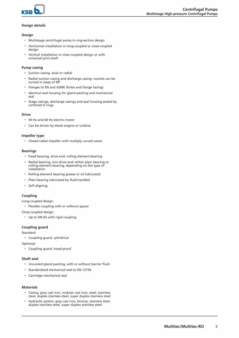
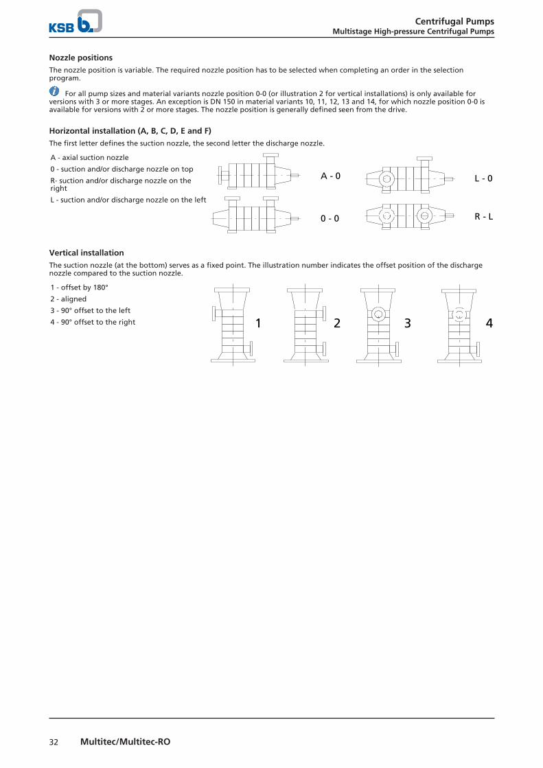
Nozzle positionsThe nozzle position is variable. The required nozzle position has to be selected when completing an order in the selectionprogram.
For all pump sizes and material variants nozzle position 0-0 (or illustration 2 for vertical installations) is only available forversions with 3 or more stages. An exception is DN 150 in material variants 10, 11, 12, 13 and 14, for which nozzle position 0-0 isavailable for versions with 2 or more stages. The nozzle position is generally defined seen from the drive.
Horizontal installation (A, B, C, D, E and F)The first letter defines the suction nozzle, the second letter the discharge nozzle.
A - axial suction nozzle
0 - suction and/or discharge nozzle on top
R- suction and/or discharge nozzle on theright
L - suction and/or discharge nozzle on the left
A - 0
0 - 0
L - 0
R - L
Vertical installationThe suction nozzle (at the bottom) serves as a fixed point. The illustration number indicates the offset position of the dischargenozzle compared to the suction nozzle.
1 - offset by 180°
2 - aligned
3 - 90° offset to the left
4 - 90° offset to the right 1 2 3 4

Centrifugal PumpsMultistage High-pressure Centrifugal Pumps
33Multitec/Multitec-RO
General assembly drawing with list of components (example)
Fig. 3: Multitec, installation type A, size 65-100
List of components
List of components
Part No. Part description Part No. Part description
106.2 Suction casing 525.1 Spacer sleeve107 Discharge casing 529 Bearing sleeve SiC108.2 Stage casing 540.1 Bush160.2 Cover 550.1 Sheet metal disc171.1 Diffuser 550.3/.4/.7/.8 Disc182.1 Foot 551.1 Spacer disc210 Shaft 561.1/.2 Grooved pin230.1 Impeller 565 Rivet231 Suction stage impeller 59-4 Balance drum320.1 Rolling element bearing 636 Lubricating nipple350.1 Bearing housing 710.1/.2 Pipe360.1 Bearing cover 731.1/.2/.3/.4/.16/.18 Pipe union381 Bearing cartridge 732.1 Bracket400.1 Gasket 81-92 Cover plate411.1/.2/.3/.4/.7/.8/.13/.23/.24/.25 Joint ring 900.4 Screw412.1/.2/.4/.5/.10 O-ring 901.1/.2 Hexagon head bolt433.1 Mechanical seal 902.1/.2 Stud441.1 Shaft seal housing 903.1/.2/.3/.4/.9 Screw plug452 Gland follower 905 Tie bolt461 Gland packing 914.1 Hexagon socket head cap
screw471.1 Seal cover 920.1/.2/.3/.4/.5 Nut502.1 Casing wear ring 931 Lock washer507 Thrower 932.2 Circlip520.1 Sleeve 940.1/.2/.3 Key523.1 Shaft sleeve 970.1 Label/plate524 Shaft protecting sleeve


KSB SE & Co. KGaAJohann-Klein-Straße 9 • 67227 Frankenthal (Germany)Tel. +49 6233 86-0www.ksb.com
1777
.5/1
1-EN
11/0
4/20
18