Embed Size (px)
Citation preview

OWNERS MANUAL | Cobolt 05-01 Series | D0106-I OCTOBER 2020
Cobolt 05-01 Series
355 nm 515 nm 640 nm
457 nm 532 nm 660 nm
491 nm 561 nm 1064 nm
High Power | Single Frequency | CW Diode pumped lasers

OWNERS MANUAL | Cobolt 05-01 Series | D0106-I OCTOBER 2020
2 | 40
OWNERS MANUAL | Cobolt 05-01 Series | D0106-I OCTOBER 2020
3 | 40
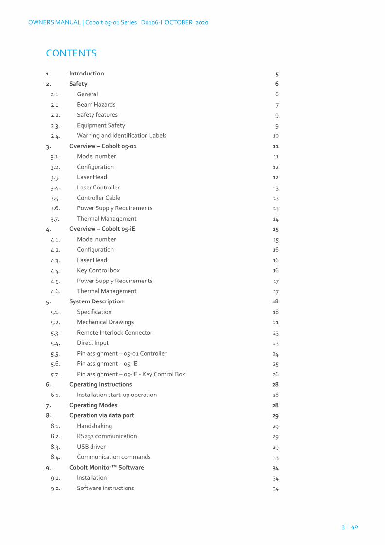
CONTENTS
Introduction 5
Safety 6
General 6
Beam Hazards 7
Safety features 9
Equipment Safety 9
Warning and Identification Labels 10
Overview – Cobolt 05-01 11
Model number 11
Configuration 12
Laser Head 12
Laser Controller 13
Controller Cable 13
Power Supply Requirements 13
Thermal Management 14
Overview – Cobolt 05-iE 15
Model number 15
Configuration 16
Laser Head 16
Key Control box 16
Power Supply Requirements 17
Thermal Management 17
System Description 18
Specification 18
Mechanical Drawings 21
Remote Interlock Connector 23
Direct Input 23
Pin assignment – 05-01 Controller 24
Pin assignment – 05-iE 25
Pin assignment – 05-iE - Key Control Box 26
Operating Instructions 28
Installation start-up operation 28
Operating Modes 28
Operation via data port 29
Handshaking 29
RS232 communication 29
USB driver 29
Communication commands 33
Cobolt Monitor™ Software 34
Installation 34
Software instructions 34

OWNERS MANUAL | Cobolt 05-01 Series | D0106-I OCTOBER 2020
4 | 40
Troubleshooting 37
Warranty and Maintenance 37
Service 37
Compliance (CDRH models only) 38
Disclaimers 39

OWNERS MANUAL | Cobolt 05-01 Series | D0106-I OCTOBER 2020
5 | 40
Introduction
The Cobolt 05-01 Series lasers are continuous-wave diode pumped laser (DPL) devices operating at a fixed wavelength
between 355 nm and 1064 nm. The lasers are built using proprietary HTCure™ manufacturing technology for ultra-
robustness in a compact hermetically sealed package.
The Cobolt 05-iE is a fully integrated laser device, including all control electronics. The Cobolt 05-iE completely
eliminates the need for an external controller, combining the trusted laser performance of Cobolt 05-01 Series in a
compact, self-contained device.
The lasers emit a very high-quality laser beam with stable characteristics over a wide range of operating conditions.
Single frequency operation provides a narrow spectral bandwidth and long coherence length. The lasers are designed
and manufactured to ensure a high level of reliability.
The Cobolt 05-01 Series lasers are intended for stand-alone use in laboratory environments or for integration as OEM
components in instruments for applications including fluorescence microscopy, flow cytometry, DNA sequencing,
HCA, Raman spectroscopy, interferometry, holography and particle analysis.
OWNERS MANUAL | Cobolt 05-01 Series | D0106-I OCTOBER 2020
6 | 40
Safety
General
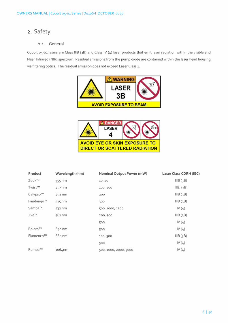
Cobolt 05-01 lasers are Class IIIB (3B) and Class IV (4) laser products that emit laser radiation within the visible and
Near Infrared (NIR) spectrum. Residual emissions from the pump diode are contained within the laser head housing
via filtering optics. The residual emission does not exceed Laser Class 1.
Product Wavelength (nm) Nominal Output Power (mW) Laser Class CDRH (IEC)
Zouk™ 355 nm 10, 20 IIIB (3B)
Twist™ 457 nm 100, 200 IIIB, (3B)
Calypso™ 491 nm 200 IIIB (3B)
Fandango™ 515 nm 300 IIIB (3B)
Samba™ 532 nm 500, 1000, 1500 IV (4)
Jive™ 561 nm 200, 300 IIIB (3B)
500 IV (4)
Bolero™ 640 nm 500 IV (4)
Flamenco™ 660 nm 100, 300 IIIB (3B)
500 IV (4)
Rumba™ 1064nm 500, 1000, 2000, 3000 IV (4)

OWNERS MANUAL | Cobolt 05-01 Series | D0106-I OCTOBER 2020
7 | 40
Symbols in the manual
WARNING – LASER RADIATION This symbol is used to call attention to important laser safety
information
WARNING – STATIC MAGNETIC FIELD This symbol is used to call attention to important
magnetic field safety information
CAUTION – GENERAL This symbol is used to call attention to important general operator and
equipment safety information
NOTICE – GENERAL This symbol is used to call attention to best practices when using the
equipment and does not indicate a hazard.
Beam Hazards
Eye and skin exposure to direct or reflected laser light is hazardous and may be extremely harmful. Always wear eye
protection appropriate to the beam wavelength and intensity. Lasers may pose a risk of igniting flammable materials
and in event of ignition gasses and fumes may be generated. All equipment used in close proximity to the laser beam
should be suitably fire resistant and the facility should be properly ventilated. It is advised to perform a risk assessment
for the facility and equipment prior to using the laser. In the case of integration into a larger system, laser safety
compliance must be evaluated in the end product.
WARNING Remove all watches, rings, and other reflective jewelry before working with lasers.
Always wear the appropriate eye protection from the wavelengths integrated into the system.
Verify the accessible emission wavelength and power before operating. Never look directly into
a laser beam.
The device must be handled by skilled personnel experienced with lasers, in a laboratory environment and with access
to adequate laser safety equipment. The laser head clearly displays a yellow warning label that shows the location of
the laser beam aperture. This label must be visible unless the laser beam is totally enclosed. If the laser does not
function, do not attempt to open any part of the device, or the warranty will be voided. Call or e-mail your local Cobolt
representative for consultancy and to request an RMA number (see back cover for contact information).
Laser radiation may ignite flammable materials and combustible gasses in the beam path and, in event of ignition,
fumes may be generated. All equipment used in close proximity to the laser beam should be suitably fire resistant and
the facility should be properly ventilated.

OWNERS MANUAL | Cobolt 05-01 Series | D0106-I OCTOBER 2020
8 | 40
CAUTION Use of controls or adjustments or performance of any procedures other than those
specified herein may result in exposure to hazardous radiation.
The table below describes the irradiance in W/cm2 and appropriate level of eye protection in terms of optical density
(OD) for each product line.
Product Wavelength (nm) Nominal Output
Power (mW)
Irradiance
(W/cm2) *
Eye protection
Requirement**
Zouk™ 355 nm 10, 20 7 OD 4
Twist™ 457 nm 100, 200 66 OD 4
Calypso™ 491 nm 200 66 OD 3
Fandango™ 515 nm 300 99 OD 4
Samba™ 532 nm 500, 1000, 1500 497 OD 4
Jive™ 561 nm 200, 300 99 OD 3
500 166 OD 4
Bolero™ 640 nm 500 166 OD 4
Flamenco™ 660 nm 100, 300 99 OD 4
500 166 OD 4
Rumba™ 1064nm 500, 1000, 2000, 3000 466 OD 4
The equations below describe how to use the nominal output power (mW) and beam area to calculate the irradiance
(W/cm2) and how to use the Warning label (Max) power (mW) and the Accessible Emission Limit (AEL) (mW) per laser
safety standard IEC 60825-1:2014 to calculated the required optical density (OD) for eye protection per wavelength.
Irradiance (W
cm2) =
110 % of Nominal Laser Power (mW)
Beam area at bottom tolerance (cm2)
Require Attenuation of Laser Safety Glasses (OD) = log10 Warning Label Power (mW)
60825 − 1 Laser Class 1 AEL (mW)
WARNING Always wear the appropriate eye protection for all of the specified emitted wavelengths.
Verify the accessible emission wavelengths and power levels on the warning label before operating.

OWNERS MANUAL | Cobolt 05-01 Series | D0106-I OCTOBER 2020
9 | 40
Safety features
The laser is equipped with all required safety features as described in the laser safety standard 60825-1. Disabling any
safety features negate the CE/CDRH compliance of this product. If any part of the delivered equipment is replaced
with a part not supplied by Cobolt or if the equipment is not properly grounded system may not conform to CE / CDRH
compliance standards listed in section 13 : Compliance (CDRH models only). Disabling any of the safety features
nullifies the CE marking and violates the laser safety standard.
Remote Interlock Connector
The remote interlock connector is a connector which permits the connection of external controls placed apart from
other components of the laser product. When the terminals of the connector are open-circuited, emission is
interrupted, and no radiation will be accessible. The remote interlock connector permits easy addition of an external
interlock in laser installation. See section Remote Interlock Connector for a detailed description of the remote
interlock circuit and operation.
Manual Shutter (Beam Stop)
The laser head is equipped with a manual shutter, which functions as the beam stop, capable of preventing human
access to laser radiation. The aperture location and the open and close positions of the shutter are indicated on the
top surface of the laser head.
Key Control
The CDRH compliant model comes with a key-switch on the controller or the key control box which must be connected
for the laser to operate. When the key is in the OFF position, the laser is prevented from emitting. The key must be
actively turned to the ON position each time the laser is powered on. When the key is removed from the system laser
radiation is not accessible.
Laser Radiation Emission Warning
The controller and the key control box incorporate information LEDs which display whether power is connected, the
laser is on, or a fault has occurred. The “ON” LED is illuminated whenever the device is emitting or could emit light.
See section 3.4 for details on the controller. The emission warning indicators are also visible in the Cobolt Monitor™
software, see section 9 for details on the control software.
Equipment Safety
Always install all power supplies used in the laser system to properly grounded power outlets. The laser head and
controller must be mounted on a common ground plane, such as an optical table. Cobolt lasers contain a laser diode
which is sensitive to electrostatic discharge (ESD).

OWNERS MANUAL | Cobolt 05-01 Series | D0106-I OCTOBER 2020
10 | 40
Warning and Identification Labels
The upper face of the laser head contains a yellow label with laser safety warning and classification information, the
wavelength and maximum power of the unit. It also shows the location of the laser beam from the aperture and
indicates the open and close positions of the manual shutter. This label must be visible unless the laser beam is totally
enclosed. A silver label showing information about the laser model, manufacturer date and location, and the power
supply voltage and current, is located on the laser head. Lasers shipped to customers in the USA also contain a label
of CDRH compliance.
Laser Notice No. 50 Label
CDRH models shipped to USA
CE marking for CDRH models only
OEM Label
Aperture Warning Labels
Manufacturer Identification Labels

OWNERS MANUAL | Cobolt 05-01 Series | D0106-I OCTOBER 2020
11 | 40
Overview – Cobolt 05-01
Cobolt 05-01 laser systems consist of four main parts: the laser head, the Controller, the Cable and the Power Supply
(not shown). The cable provided should always be used to connect the laser head with the Controller. Always install
the laser system to a properly grounded power outlet. If any part of the supplied equipment is replaced with a part not
supplied by Cobolt or if the equipment is not properly grounded system may not conform to CE / CDRH compliance
standards listed in section 13 : Compliance (CDRH models only). Disabling any of the safety features nullifies the CE
marking and violates the laser safety standard.
Model number
Cobolt lasers are sold in two configurations: CDRH and OEM, described in section 3.2. The model numbers are
composed as described below.
Wavelength
Power Configuration:
500 = RS-232, CE / CDRH Compliant
600 = RS-232, OEM
700 = USB, CE / CDRH Compliant
800 = USB, OEM
xxx = OEM customization
XXXX – 05 – 01 – XXXX – XXX
Laser Head
Controller Cable

OWNERS MANUAL | Cobolt 05-01 Series | D0106-I OCTOBER 2020
12 | 40
Configuration
CDRH Compliant
The CDRH compliant system is supplied with a key switch on the Controller, which must be connected, along with a
remote interlock connector. Once power is supplied, laser radiation starts when the key is turned from the OFF
position to the ON position. The status of operation can be monitored via LEDs on the Controller. Setting the key to
its OFF position puts the laser in stand-by mode. The CDRH model is CE compliant.
The standard CDRH model consists of:
• Laser head
• Controller with key switch
• Keys
• 1 m Controller Cable
• 15 V / 6 A DC power supply unit
OEM
The OEM system is supplied without a key switch on the controller. Connecting the power supply to the controller
initiates an automatic start-up sequence. If the remote interlock is connected, laser radiation will start automatically
as soon as power is supplied, and internal temperatures are stabilized.
The OEM model consists of:
• Laser head
• Controller
• Controller Cable
• 15 V / 6 A DC power supply unit
Laser Head
The laser head contains pump diode, laser cavity, beam shaping optics and thermoelectric coolers (TEC) for
temperature control of the cavity and pump diode. The laser head contains an optical feed-back loop which ensures
long-term power stability of the emitted visual beam. The laser head features a manual mechanical shutter as well as
a laser hazard label and a laser classification label. The Laser Head gets electrical power and control signals from the
Controller via a 26-pin HD Sub-D cable. All products covered in this manual are available with all CDRH and OEM
controller configurations.

OWNERS MANUAL | Cobolt 05-01 Series | D0106-I OCTOBER 2020
13 | 40
Laser Controller
The Controller supplies driving current and control signals to the Laser Head. All Laser Heads are delivered with a
controller. The operation set points are specific to each Laser Head and have been fixed during manufacturing. The
operation set points are stored in the laser head so the controller can be interchanged or replaced.
The status of the laser operation is given via LED indicators:
POW Green Power is supplied.
ON Orange Laser emission is on. This light is on in modulation mode if laser emission is possible.
LOCK Orange Laser light is on and the output power has been locked to set point. The laser is
operating according to specifications.
ERROR Red An error has occurred.
When power is supplied to the Controller, regardless of on/off state, the temperature control elements are operating
to reach set point values. The Controller includes a remote interlock connector, pin 1-2 according to Section 5.5 and
5.6. The operation of the laser can be controlled and monitored via the data port that supports either USB or RS-232
commands. See Section 8.4 for further details. RS-232 controllers may also be delivered with a RS-232 to USB adaptor.
Controller Cable
The controller cable connects the laser head to the Controller. The standard (CE compliant) cable length is 1 m. The
cable has a minimum bending radius of 8 cm. When connected care should be taken not to bend or break any of the
26 pins.
Power Supply Requirements
An appropriate Power Supply Unit (PSU) is supplied by Cobolt with the laser and must be plugged into a properly
grounded standard power outlet. The output from this PSU is 15 VDC / 6 A. The power supply accepts 100 – 240 V AC
and 50-60 Hz. Ripple and noise 1% peak-peak max, 20 MHz bandwidth. The accepted voltage range for the Cobolt
Bolero™ is 15 V - 28 VDC; all other Cobolt 05-01 lasers accept 11 V - 28 VDC. Full performance is only guaranteed at
15 VDC / 6 A.
The power supply provided with Cobolt 05-01 lasers are certified to perform in an ambient temperature of 40°, when
integrating this power supply into a larger system care must be taken to ensure that the power supply is not exposed
to temperatures above 40°C.

OWNERS MANUAL | Cobolt 05-01 Series | D0106-I OCTOBER 2020
14 | 40
Thermal Management
To ensure operation within given specifications and for the warranty to be valid, the Laser Head must be attached to
a heat sink providing a thermal resistance of < 0.2 K/W or < 0.18 K/W for Cobolt Bolero™. This value is the difference
between the maximum allowed Laser Head base plate temperature 50ºC or 45° C for Cobolt Bolero™ and the
maximum specified ambient temperature at the air-heatsink interface which is 40ºC or 35°C for Cobolt Bolero™,
divided by the maximum power dissipated from the laser which is 50W or 55 W for Bolero™. The mounting surface
should be flat (within 0.05 mm over mounting surface). It is recommended to use a thermal heat compound between
the Laser Head and the heat sink to provide good thermal contact. The Cobolt ‘HS-04 Laser Head Heatsink with fans’
meets these requirements, see https://hubner-photonics.com/ for more information on heat sinks. For assistance in
thermal management and system integration, please contact Cobolt’s technical support.
Heat Sink Requirements (Bolero™ shown in red, all other products in blue) and typical maximum heat dissipation for
Cobolt 05-01 lasers.

OWNERS MANUAL | Cobolt 05-01 Series | D0106-I OCTOBER 2020
15 | 40
Overview – Cobolt 05-iE
Cobolt 05-iE laser systems consist of three main parts: the laser head, the key control box, and the Power Supply (not
shown). The cable provided should always be used to connect the laser head with the Controller. Always install the
laser system to a properly grounded power outlet. If any part of the supplied equipment is replaced with a part not
supplied by Cobolt or if the equipment is not properly grounded system may not conform to CE / CDRH compliance
standards listed in section 13 : Compliance (CDRH models only). Disabling any of the safety features nullifies the CE
marking and violates the laser safety standard.
Model number
Cobolt lasers are sold in two configurations: CDRH and OEM, described in section 3.2. The model numbers are
composed as described below. The Cobolt 05-iE lasers are not offered with the communication configurable between
USB and RS-232 as all lasers are delivered as standard with the options accessible.
Wavelength
Power Configuration:
1100 = CE / CDRH Compliant
1200 = OEM
xxxx = OEM customization
XXXX – 05 – 01 – XXXX – XXX
Laser Head

OWNERS MANUAL | Cobolt 05-01 Series | D0106-I OCTOBER 2020
16 | 40
Configuration
CDRH Compliant
The CDRH compliant system is supplied with a key switch on the key control box, which must be connected, along
with a remote interlock connector. Once power is supplied, laser radiation starts when the key is turned from the OFF
position to the ON position. The status of operation can be monitored via LEDs on the key control box. Setting the
key to its OFF position puts the laser in stand-by mode. The CDRH model is CE compliant.
The standard CDRH model consists of:
• Laser head
• Key control box
• Keys
• 12 V / 6.67 A DC power supply unit
OEM
The OEM system is supplied without a key switch on the key control box. Connecting the power supply to the to the
laser head initiates an automatic start-up sequence. If the remote interlock is connected, laser radiation will start
automatically as soon as power is supplied, and internal temperatures are stabilized.
The OEM model consists of:
• Laser head
• 12 V / 6.67 A DC power supply unit
Laser Head
The laser head contains pump diode, laser cavity, beam shaping optics and thermoelectric coolers (TEC) for
temperature control of the cavity and pump diode. The laser head contains an optical feed-back loop which ensures
long-term power stability of the emitted visual beam. The laser head features a manual mechanical shutter as well as
a laser hazard label and a laser classification label. The Laser Head gets electrical power via a 4 pin Molex connector
directly from the DC power supply. All products covered in this manual are available with both CDRH and OEM
configurations.
Key Control box
The key control box allows the user to operate the laser with a CDRH-compliant key-switch. The control box has LEDs
to indicate the laser status. When power is supplied to the laser head, regardless of on/off or key-switch state, the
temperature control element will be active to reach its set point values.
The status of the laser operation is given via LED indicators:
ON Orange Laser emission is on.
ERROR Red An error has occurred.

OWNERS MANUAL | Cobolt 05-01 Series | D0106-I OCTOBER 2020
17 | 40
Power Supply Requirements
An appropriate Power Supply Unit (PSU) is supplied by Cobolt with the laser and must be plugged into a properly
grounded standard power outlet. The output from this PSU is 12 VDC / 6.67 A. The power supply accepts 100 – 240 V
AC and 50-60 Hz. Ripple and noise 1% peak-peak max, 20 MHz bandwidth. Cobolt 05-iE lasers accept 11.2 V – 13.2
VDC. Full performance is only guaranteed at 12 VDC / 6.67 A.
The power supply provided with Cobolt 05-iE lasers are certified to perform in an ambient temperature of 40°, when
integrating this power supply into a larger system care must be taken to ensure that the power supply is not exposed
to temperatures above 40°C.
Thermal Management
To ensure operation within given specifications and for the warranty to be valid, the Laser Head must be attached to
a heat sink providing a thermal resistance of < 0.15 K/W. This value is the difference between the maximum allowed
Laser Head base plate temperature (45ºC) and the maximum specified ambient temperature at the air-heatsink
interface (35°C), divided by the maximum power dissipated from the laser (65 W for the highest power models at high
ambient temperatures). The mounting surface should be flat within 0.05 mm over mounting surface. It is
recommended to use a thermal heat compound between the Laser Head and the heat sink to provide good thermal
contact. The Cobolt ‘HS-05 Laser Head Heatsink with fans’ meets these requirements, see https://hubner-
photonics.com/ for more information on heat sinks. For assistance in thermal management and system integration,
please contact Cobolt’s technical support.
Heat Sink Requirements and typical maximum heat dissipation for Cobolt 05-iE Series.

OWNERS MANUAL | Cobolt 05-01 Series | D0106-I OCTOBER 2020
18 | 40
System Description
The information presented here is believed to be accurate and is subject to change without notice. The specifications
contained herein cannot be guaranteed outside of normal operational conditions. The output power can be adjusted
using control commands, see Section 8.4. Specifications are guaranteed at 100% of nominal power after warm-up is
complete.
Specification
Optical Specifications
Centre wavelength1 Output power (mW)
Zouk™ 354.8 ± 0.3 nm 10, 20
Twist™ 457.0 ± 0.3 nm 100, 200
Calypso™ 2 491.5 ± 0.3 nm 200
Fandango™ 514.8 ± 0.3 nm 300
Samba™ 532.1 ± 0.3 nm 500, 1000, 1500
Jive™ 561.2 ± 0.3 nm 200, 300, 500
Bolero™ 639.6 ± 0.3 300, 500
Flamenco™ 659.6 ± 0.3 nm 100, 300, 500
Rumba™ 1064.2 ± 0.6 nm 500, 1000, 2000, 3000
ZoukTM Twist™ CalypsoTM Fandango™ SambaTM JiveTM Bolero™ FlamencoTM RumbaTM
Beam Diameter (µm) 700 ± 50 µm 1000 ± 50
Divergence (full angle) (mrad) < 0.8 < 1.2 mrad < 1.4 < 1.5 < 1.6
Noise 20 Hz – 20 MHz (pk-pk) < 2 % < 5 % < 2 % < 1 % < 7 % < 1 %
Noise 20 Hz – 20 MHz (rms) < 0.2% < 0.5% < 0.2% < 0.1 % < 1.0 % < 0.1 %
Long-term power stability < 2 % (±3 ºC, 8 hours)
Spatial mode TEM00, M2 < 1.1
Spectral linewidth < 1 MHz (< 0.001 pm)
Wavelength stability < 1 pm ( ± 3°C, 8 hours)
Coherence length > 100 m
Beam symmetry at aperture > 0.90 : 1 > 0.95 : 1
Beam waist location (vs exit) 200 mm
Beam angle accuracy < 5 mrad
Beam position accuracy < 0.25 mm
Beam pointing stability < 10 µrad/ºC, (typical < 5 µrad/ºC) (10-40ºC)
Polarization ratio > 100:1 (linear, vertical)
Residual IR emission < 1 mW
1. The wavelength is specified in air.
2. Cobolt Calypso™ 491 nm laser is not yet available in the 05-iE package

OWNERS MANUAL | Cobolt 05-01 Series | D0106-I OCTOBER 2020
19 | 40
Operation and Environmental Specifications
05-01 Bolero 05-01 05-iE
Power supply 15 VDC, 6 A 12 V, 6.67 A
Power consumption, total system < 65 W (typical < 30 W)
Maximum Laser Head baseplate temperature 50ºC 45°C 45 °C
Ambient temperature, operation 10 – 40 ºC 10 – 35 ºC 10 – 35 ºC
Heat sink thermal resistance, Laser Head < 0.2 K/W < 0.18 K/W < 0.15 K/W
Intended use environment Laboratory (indoor)
Pollution Degree 2
Ambient temperature, storage -10°C to +60 ºC
Humidity 0- 60 % RH non-condensing
Ambient Air pressure 950-1050 mbar
Warm-up time, from OFF < 3 min
Communication protocol USB or RS 232 USB and RS 232
Electrical Interfaces
All equipment connected to the system should be limited energy as described by IEC 61010:1.
Cobolt 05-01 Lasers
Interfaces Location Connector
Input power Laser Head Kycon KPJX-45, 4-pin
To Controller Laser Head HD-sub 26-pin, male
To Laser Head Controller HD-sub 26-pin, female
Data port Controller USB-type mini B
Remote interlock Controller 6 pin Molex 90130-3206 (pin 1 and 2)
Direct Inputs Controller 6 pin Molex 90130-3206 (pin 3)
Cobolt 05-iE Lasers
Interface Location Connector / pins
Input power Laser Head 4 pin Molex (43650-0421)
Remote interlock Laser Head OEM : CTRL 14 pin Molex 87832-1420 (pin 1 and 2)
Direct Input Laser Head OEM : CTRL 14 pin Molex 87832-1420 (pin 12)
Data port Laser Head USB-type mini B
To Key control box Laser Head CTRL 14 pin Molex (87832-1420)
To Laser Head Key control box VGA D-SUB 15-pin male
Remote Interlock Key control box CDRH : 3.5 mm audio female

OWNERS MANUAL | Cobolt 05-01 Series | D0106-I OCTOBER 2020
20 | 40
Mechanical Interfaces
05-01 05-iE
Laser Head 125 x 70 x 45 mm
(4.9 x 2.8 x 1.8 inches)
134 x 70 x 45 mm
(5.3 x 2.8 x 1.8 inches)
Controller / Key box 190 x 72 x 28 mm
(7.5 x 2.8 x 1.1 inches)
82 x 56.6 x 32 mm
(3.2 x 2.2 x 1.3 inches)
Power Supply 115 x 50 x 35 mm
(4.6 x 2.0 x 1.4 inches)
145 x 60 x 32 mm
(5.7 x 2.4 x 1.3 inches)
Fixation holes, Laser Head = 4x 4.5 mm (M4)
115 mm x 55 mm
= 4x 4.5 mm (M4)
134 mm x 55 mm
Fixation holes, Controller = 4x 6.4 mm (M6)
178 mm x 51 mm
n/a
Laser Head weight < 0.6 kg

OWNERS MANUAL | Cobolt 05-01 Series | D0106-I OCTOBER 2020
21 | 40
Mechanical Drawings
Laser Head 05-01
Laser head mechanical outline. Dimensions in mm [inches].
Laser Controller Gen 5b – 05-01
OWNERS MANUAL | Cobolt 05-01 Series | D0106-I OCTOBER 2020
22 | 40
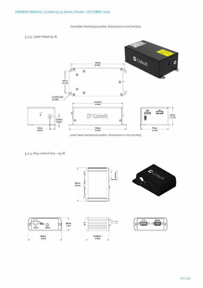
Controller mechanical outline. Dimensions in mm [inches].
Laser Head 05-iE
Laser head mechanical outline. Dimensions in mm [inches].
Key control box - 05-iE

OWNERS MANUAL | Cobolt 05-01 Series | D0106-I OCTOBER 2020
23 | 40
Remote Interlock Connector
The remote interlock connector is located at pin 1 and 2 of the Molex connector on the control I/O connector. The
connector can be short-circuited with an interlock jumper (included at delivery) for operation of the laser. To use the
remote interlock connector with an external switch, connect a pin 1 and 2 on a Molex plug. After the remote interlock
connector has been opened the laser will need to be reset by disconnecting from and then reconnecting to the power
supply in order to start again. Alternatively, it can be re-started using a special sequence of commands, see Section
8.4 for further details. The signal level is between 0 V and +5 V with a pull up resistor, and the current required to
ground the remote interlock connector is 5 mA. The time delay in the hardware is < 1 ms, but after filtering by the
firmware the reaction time is extended to < 20 ms.
Direct Input
The Direct Input is a control feature that enables turning the laser ON and OFF using a 5 VDC signal. After having
configured the control software for Direct Input operation (factory set or by executing @cobasdr 1), the laser can only
start-up when a 5 VDC is applied to the appropriate pin on the Control I/O connector with 0 VDC on pin 2 as reference.
Shifting the signal to 0 VDC on the appropriate Direct Input pin will turn the laser off and put the laser in stand-by
mode (status LED:s is POW and not flashing). See section 5.5 and 5.6 for pin assignment.
NOTICE This function is not available for CDRH compliant models. The Direct Input ON/OFF control feature
should never be used as remote interlock connector. A remote interlock socket is provided for this purpose
on the laser head. This input only controls the ON/OFF state of the laser and cannot be used to modulate
the power output.

OWNERS MANUAL | Cobolt 05-01 Series | D0106-I OCTOBER 2020
24 | 40
Pin assignment – 05-01 Controller
All equipment connected to the system should be limited energy as described by IEC 61010:1.
Controller I/O connector
Manufacturer Molex 90130-3206, mates with 90143-0006.
Pin Function Signal Details
1 Remote Interlock 3.3 V, Pull up
2 0 V - GND
3 Direct Input OFF = 0 – 1.5 V (In)
ON = 3.0 – 12 V (In)
4 --
5 LED 1B (LASER ON) 5 V , 470 Ω (out)
6 LED 2 (ERROR) 5 V , 470 Ω (out)
Power supply connector
Kycon KPJX-4S, mates with Kycon KPPX-4P. Grounded shield.
Pin Function Pin Function (Bolero)
1 0 V 1 0 V
2 +11-28 VDC 2 +15 – 28 VDC
3 0 V 3 0 V
4 +11-28 VDC 4 +15 – 28 VDC
Data connector
Connector USB-type, mates with connector mini-B.
Pin Function (USB) Function (RS-232)
1 +5 V Not connected
2 D- RS-232_TX
3 D+ RS-232_RX
4 Not connected Not connected
5 0 V (GND) 0 V (GND)

OWNERS MANUAL | Cobolt 05-01 Series | D0106-I OCTOBER 2020
25 | 40
Pin assignment – 05-iE
All equipment connected to the system should be limited energy as described by IEC 61010:1.
Laser head I/O - CTRL
The pin configuration for the 14 pin Molex connector on the laser head is described in the table below.
Pin Function Signal Detail
1 Remote interlock 3.3 V, Pull up
2 0 V – Ground
3 0 V – Ground
4 RS-232 TX
5 RS-232 RX
6 LED 1A (LASER ON) 3.3 V , 470 Ω (out)
7 LED 1B (LASER ON) 3.3 V , 470 Ω (out)
8 LED 2 (ERROR) 3.3 V , 470 Ω (out)
9 --
10 --
11 Key Switch
12 Direct Input OFF = 0 – 1.5 V (In) ON = 3.0 – 12 V (In)
13 0 V – Ground
14 --
Data connector - USB
Connector USB-type, mates with connector mini-B.
Pin Function
1 +5 V
2 D-
3 D+
4 Not connected
5 0 V (Ground)
14 pin Molex socket on laser head
USB Connector

OWNERS MANUAL | Cobolt 05-01 Series | D0106-I OCTOBER 2020
26 | 40
Power connector
The pin configuration for the Molex 4-pin connector is described below.
Pin Function
1 0 V – Ground
2 0 V – Ground
3 + 12 V - DC
4 + 12 V - DC
Pin assignment – 05-iE - Key Control Box
All equipment connected to the system should be limited energy as described by IEC 61010:1.
Laser head
The pin configuration for the 15 pin Sub-D (VGA) connector on the key control is described in the table below.
Pin Function
1 LED 1A (LASER ON)
2 LED 2 (ERROR)
3 --
4 0 V – Ground
5 Key Switch
6 --
7 RS-232 TX
8 RS-232 RX
9 --
10 0 V – Ground
11 Remote interlock
12 --
13 --
14 --
15 0 V – Ground
4 pin Molex socket on laser head
15 pin Sub-D connector on the laser head

OWNERS MANUAL | Cobolt 05-01 Series | D0106-I OCTOBER 2020
27 | 40
Data connector – RS 232
The pin configuration for the 9 pin Sub-D (serial) connector on the key control is described in the table below.
Pin Function
1 --
2 RS-232 TX
3 RS-232 RX
4 --
5 0 V – Ground
6 --
7 --
8 --
9 --
9 pin Sub-D connector for RS-232 communication

OWNERS MANUAL | Cobolt 05-01 Series | D0106-I OCTOBER 2020
28 | 40
Operating Instructions
As standard, all lasers are delivered in Auto-start mode. As soon as power is supplied to the system the temperature
control elements are operating to reach set-point values and the laser emission will start, unless the key-switch is
enabled (CDRH model).
Installation start-up operation
1. Mount the Laser Head on a suitable heat sink (see Section 3.5).
2. Ensure that the remote interlock jumper is connected.
3. Connect the Laser Head to the controller or key control box with the Cable and fasten screws at both
ends.
4. Connect the power supply to the mains outlet and then to the system.
5. The laser now goes through the following auto-start sequence:
• Temperature stabilization (1-2 min). Status LEDs: POW flashing, then POW goes on.
• Turn the key switch to start the laser. Status LEDs: ON goes on (CDRH model only)
• The laser starts (light is emitted) in a constant warm-up current constant for 60 sec.
Status LEDs: ON goes on, either in the software (05-iE) or on the controller (05-01).
• The laser locks to pre-set output power (<2 min) and operates according to specifications.
Status LEDs: LOCK goes on, either in the software (05-iE) or on the controller (05-01).
NOTICE If the power does not match the power as stated on the test sheet see Section 12: Service for
more information.
Operating Modes
There are two operating modes: constant power and constant current. The default mode for Cobolt 05-01 series lasers
when shipped is constant power. In constant power mode the power is monitored on an internal photodiode, and this
is used to regulate the current to maintain a constant power level. In constant current mode the laser runs at a set
current level.

OWNERS MANUAL | Cobolt 05-01 Series | D0106-I OCTOBER 2020
29 | 40
Operation via data port
To connect a Cobolt 05-01 Series lasers to a data port use mini-USB connection, the appropriate cable is provided with
all lasers. For Cobolt 05-01 lasers check configuration of your system to determine which communication protocol has
been delivered.
Handshaking
Under no circumstances does the system initiate communication; it only transmits characters in response to a
message. Every message generates a response, either a numerical value or the acknowledgment string “OK”. In the
event that the system receives a message that it cannot interpret, it responds: “Syntax error: illegal command”. Every
system response is terminated by a carriage return (ASCII 13) and a full stop is used with floating numbers.
RS232 communication
Cobolt 05-01 lasers are offered with an optional RS-232 or USB configuration. The data connector will be labeled with
the communication protocol, this section only applies to theRS-232 configured controllers. Cobolt 05-iE lasers are all
delivered with RS-232 communication available via the key control box or I/O connector on the laser head. The system
is shipped from the factory with a fixed baud rate (115200). The other serial port parameters are: 8 data bits, 1 stop bit
and no parity. Hardware flow control is not supported. Each command must be terminated by a carriage return. All
commands are case-sensitive. Leading and trailing white space is ignored, but command arguments must be
delimited by a single space character (ASCII 32).
USB driver
The Cobolt USB driver is only required for Windows 8 and earlier (e.g Windows 7, Vista, XP). When using Cobolt
Monitor™ with Windows 10, the USB device is automatically detected. The USB driver can be downloaded from the
Hübner Photonics website (https://hubner-photonics.com/). When installed, a virtual COM port will be created to
communicate with the laser.
NOTICE If using an RS-232 configured device, do not install the USB driver, regardless of operating
system.

OWNERS MANUAL | Cobolt 05-01 Series | D0106-I OCTOBER 2020
30 | 40
To install the USB driver in Windows 7 follow these instructions:
1. Go to the Control Panel and choose Hardware and Sound.
2. Under the Devices and Printers section, choose Device Manager.
3. Under Other devices, find the device called Cobolt Laser Driver. Right-click it and chose Update Driver
Software.

OWNERS MANUAL | Cobolt 05-01 Series | D0106-I OCTOBER 2020
31 | 40
4. On the next screen chose the Browse my computer for driver software option.
5. Click browse, and find folder on your computer where the USB driver is stored.

OWNERS MANUAL | Cobolt 05-01 Series | D0106-I OCTOBER 2020
32 | 40
6. Windows security may warn you that the publisher of the driver is unverified. Choose Install this driver
software anyway.
7. The installation should now be complete.

OWNERS MANUAL | Cobolt 05-01 Series | D0106-I OCTOBER 2020
33 | 40
Communication commands
The laser is delivered with in Auto-start mode (see section 6.1 for Auto-start sequence description). As long as power
is supplied to the system the temperature control elements are always operating to reach set-point values and the
laser will be idle waiting for the next command. All arguments are in lower case and separated by a space (ASCII 32).
For more information during system integration contact your local sales representative.
Command Function Argument Returned value
@cob1 Laser ON after interlock Forces the laser into Autostart without checking if autostart is enabled (OEM models).
l? Get laser ON/OFF state 0 = OFF
1 = ON
l1 Laser ON Requires autostart disabled. Use this command for manual ON (OEM models).
l0 Laser OFF Use this command for manual OFF (OEM models).
p? Get set output power Float (W)
p Set output power Float (W)
pa? Read output power Float (W)
i? Get drive current Float (A)
slc Set drive current Float (A)
ilk? Get interlock state 0 = interlock closed (OK)
1 = interlock open
leds? Status of 4 LEDs Int [0:15] Bit 0 = “POWER ON” Bit 1 = “LASER ON” Bit 2 = “LASER LOCK” Bit 3 = “ERROR” 1 = LED on 0 = LED off
f? Get operating fault 0 = no fault 1 = temperature error 3 = open interlock 4 = constant power fault
cf Clear fault
sn? Get serial number 32-bit unsigned integer
hrs? Get system operating hours Float
For re-starting the laser with commands after having opened the remote interlock switch, execute “cf” for clear fault
followed by “@cob1” to restart the laser. This command forces the laser into Auto-start enabled so Auto-start must
be disabled if this is the required set up. On CDRH models the key switch is the only way to re-start.

OWNERS MANUAL | Cobolt 05-01 Series | D0106-I OCTOBER 2020
34 | 40
Cobolt Monitor™ Software
The Cobolt Monitor™ software provides a graphical way to monitor the laser performance and to change power,
operation mode and other settings. The software can connect to the laser either via RS-232 port or via USB, depending
on the system configuration. When using Cobolt Monitor™ with Windows 10, the USB device is automatically
detected. When using Windows 8 or earlier the USB driver must be installed manually and can be downloaded from
the Cobolt website (https://hubner-photonics.com/ ), see section 8.3.
Cobolt Monitor™ has been tested with operative systems Windows 10, Windows 7, Windows 8, Windows XP and Vista.
Microsoft .NET 2.0 is required to run the Cobolt Monitor™ software. Most computers with operative systems have this
included as standard.
Installation
Download the latest version of the Cobolt Monitor™ software from https://hubner-photonics.com/ . The Cobolt
Monitor™ software is a stand-alone executable, the executable file is packaged with other files needed to run the
program in a .zip file. Save the .zip file and extract all files. The folder created after extracting the files can be placed
on any storage device and Cobolt Monitor™ can be run from there. All files and folders contained in the .zip file must
be present for the program to function properly.
Software instructions
The software automatically searches for Cobolt devices every 5 seconds and automatically connects the laser if
detected. The software can identify USB connected lasers as well as RS232 connected lasers.
The first Cobolt Monitor™ window that appears in the Cobolt Monitor software.
Once the laser is connected it can be controlled from the box dedicated for the laser. The interface, found in the
following figure, is intended for typical user cases. Only the relevant information is presented on this level, displaying
only the status the laser is in and relevant choices to make. Here follows a short description of how to use the Cobolt
Monitor™ software on this level.

OWNERS MANUAL | Cobolt 05-01 Series | D0106-I OCTOBER 2020
35 | 40
Laser successfully connected.
Laser ON – Turns the laser ON. If the laser is in autostart mode this is equivalent to “restart”.
Laser OFF – Turns the laser OFF.
Mode – Gives a choice of operational modes possible to choose for the laser model. For 05 series lases Constant Power
or Constant Current operation can be chosen. Only relevant choices are presented to the mode of operation chosen.
Commands – opens a command communications window to send commands directly to the laser.
Message – highlights important information of the laser status to the user.
Disconnect – allows the user to disconnect from the Cobolt Monitor™ software in a controlled way.
NOTICE The communication cable should not be removed when the software is in connect state. The
communication may then malfunction and this might require a power restart of the system. To disconnect
the laser, click “Disconnect” or close Cobolt Monitor™ completely. It is also possible to disconnect by
powering the laser OFF. In this case Cobolt Monitor™ will automatically close the window for that laser.
Clear Fault - is displayed in the event of a fault. The user can deal with the cause of the fault and then press “Clear
Fault” and then restart the laser by clicking “Laser ON”. Example: if the remote interlock loop is open the user must
make sure the loop is closed again before issuing a “Clear Fault” followed by “Laser On”.
More –an additional Cobolt Monitor™ window will open containing more detailed information of that laser’s status.

OWNERS MANUAL | Cobolt 05-01 Series | D0106-I OCTOBER 2020
36 | 40
Cobolt Monitor™ software expanded to for more detailed monitoring.
TEC Settings – shows the running status and the fault status for the laser’s internal thermoelectric coolers (TEC).
Laser Operation Mode and Settings - displays the set laser power. The user can switch between constant power
mode and constant current mode. Likewise, there are boxes to set the constant power level and constant current level.
The output power (as monitored measured on an internal photodiode) and the current through the laser pump diode
are both displayed.
Autostart Program - displays whether the laser is in CDRH or OEM mode and displays the current laser operational
status. Direct input enabled state is set here, see section 5.4. There are also buttons to “abort” the autostart sequence
or to “restart” the laser after a fault.
NOTICE Specifications are only guaranteed in constant power mode, at 100% of nominal power.
Fault Status – displays ERROR messages. In the event of an ERROR, the laser action is stopped. When the reason for
the ERROR event is understood and the problem is addressed the fault status can be cleared with “Clear Fault”. If the
Autostart Program is enabled, click restart to restart the laser.
LED Status - displays the LED Status. For Cobolt 05-01 lasers this will correspond to the LEDs that are currently
illuminated on the Controller, see section 3.4. These are displayed even if the laser is in OEM mode.

OWNERS MANUAL | Cobolt 05-01 Series | D0106-I OCTOBER 2020
37 | 40
Troubleshooting
In the unlikely case of a problem occurring, use the table below to help identify the error. Some faults can be fixed
remotely. Back reflections into the cavity can cause instability of operation. Isolators are available as an option. In case
of a sudden voltage drop the laser will turn itself off and restart. If it is in CDRH configuration it will require that the
key is turned on again. Contact Cobolt support or your local representative to identify corrective action.
LEDs Status Explanation Action
off flashing
POW x Mains power off Check connections
POW x Temperatures not stabilized Check if heatsink is sufficient
LOCK x Laser cannot lock in constant power, current limit has been reached
Check for back reflections. Contact the factory.
ERROR on Error in laser parameters If lights at start-up check cable connections, if lights >5s after start-up contact the factory.
Warranty and Maintenance
Cobolt provides a warranty of 12 months on Cobolt Zouk™, Twist™, Fandango™, Bolero™ and 24 months on Cobolt
Calypso™, Samba™, Jive™, Flamenco™, and Rumba™ with unlimited number of operation hours. The laser systems
are designed for modular repair or replacement in the event that the Laser Head or Controller malfunctions. Warranty
is invalid if the laser system is operated outside of the specific limits and conditions as outlined in this document.
The Cobolt lasers are contained in sealed enclosures and should not be opened for any reason. Disassembly of any
part of the system (including the cable) means the system no longer complies with the EMC standards and will void
the warranty. All laser parameters are set at the factory, and there are no adjustments required. Maintenance is limited
to wiping dirt off the enclosures and cleaning the aperture.
Service
Due to accuracy tolerances, calibration differences and allowed power drift there may be discrepancies between the
Cobolt measurement of the optical output power and the customer measurement equipment. If the output power
deviates from the reported value, please contact your local Cobolt representative for an online re-calibration. If the
laser does not function, do not attempt to open any of the units, or the warranty will be voided. Contact your local
Cobolt representative for consultancy and to request an RMA number (see back cover for contact information). If an
RMA number is issued and the laser needs to be shipped back to Cobolt or your local representative, please pack the
complete system for shipment using the original package or equivalent. Ensure the unit is free from thermal paste
before packing. The warranty covers repair or replacing the unit at the option of Cobolt.

OWNERS MANUAL | Cobolt 05-01 Series | D0106-I OCTOBER 2020
38 | 40
Compliance (CDRH models only)
The CDRH model lasers (-100, and -5/700) are designed and manufactured to comply with the EC Low Voltage
Directive and the EC EMC Directive in the CDRH-compliant configuration. Cobolt 05-01 laser system consist of a laser
head, 1 m controller cable, controller, key and Cobolt-supplied power supply. Cobolt 05-iE laser systems consist of a
laser head, key control box, < 1 m key control box cable, key and a Cobolt-supplied power supply. All equipment must
be mounted on a common ground plane, such as an optical table. If any part of the delivered equipment is replaced
with a part not supplied by Cobolt or if the equipment is not properly grounded, the system may not conform to CE /
CDRH compliance standards listed in section 13. Disabling any of the safety features nullifies the CE marking and
violates the laser safety standard.
The following harmonized and limits standards have been applied:
Electrical Safety: EN 61010-1, IEC-61010-1, UL 61010-1 (Limited Energy System)
Laser Safety/Class IEC-60825-1 , CDRH 21 CFR 1040.10 and 1040.11
EMC
4-2
IEC 61326-1
EN 55011 Electromagnetic Emission , Class A
FCC Part 15, subpart B, class A
Electromagnetic Immunity – Table 1 : Basic Electromagnetic Environment
EN 61000-4-2 Electrostatic Discharge
±4 kV contact discharge and
±2 kV, ±4 kV, ±8 kV air discharge
EN 61000-4-3 Radiated electromagnetic fields
80 – 1000 MHz, 3 V/m with 80 % AM @ 1 kHz
1.4 – 2.0 GHz, 3 V/m with 80 % AM @ 1 kHz
2.0– 2.7 GHz, 1 V/m with 80 % AM @ 1 kHz
EN 61000-4-4 Fast transient / Burst
AC Power input port ± 1,0 kV
EN 61000-4-5 Surge
AC Power input port ±0,5 kV, ±1,0 kV Com. Mode
AC Power input port, ±0,5 kV Diff. Mode
EN 61000-4-6 Conducted Immunity
3 V with 80 % AM @ 1 kHz
EN 61000-4-11 Dips and Interruptions
50 Hz and 60 Hz. Test voltages: 100 V and 230 V
RoHS EU Directive 2011/65/EU
Contact your sales representative for a copy of the full Declaration of Conformity.

OWNERS MANUAL | Cobolt 05-01 Series | D0106-I OCTOBER 2020
39 | 40
Disclaimers
Cobolt will assume no responsibility for damage incurred by faulty customer equipment, such as measurement
equipment, cables etc, used in conjunction with Cobolt lasers. Cobolt makes no warranty of any kind with regard
to the information contained in this guide, included but not limited to, implied warranties of merchantability and
suitability for a particular purpose. Cobolt shall not be liable for errors contained herein nor for incidental or
consequential damages from the furnishing of this information. No part in this manual may be copied,
reproduced, recorded, transmitted, or translated without the express written permission by Cobolt.

Australia
Warsash Scientific Pty Ltd
www.warsash.com.au
_________________________________
Benelux
Laser 2000 Benelux CV
www.laser2000.nl
___________________________
Brazil
Photonics Instrumentos
www.photonics.com.br
_________________________________
China
DynaSense Photonics Co. Ltd.
www.dyna-sense.com
_________________________________
Estonia, Latvia and Lithuania
Optek Ltd
www.optek.lv
_________________________________
France
Optoprim
www.optoprim.com
India
Spectral Instrument System
www.spectralinstruments.com
_________________________________
Israel
Lahat Technologies Ltd
www.lahat.co.il
_________________________________
Italy
Crisel Instruments
www.crisel-instruments.com
_________________________________
Japan
Kantum Electronics Co Ltd
www.kantum.co.jp
Pneum Co, Ltd Japan
www.pneum.co.jp
_________________________________
Poland
Amecam
www.amecam.pl
_________________________________
Russia and Belarus
Azimuth Photonics
www.azimp.ru
Russia and Belarus
Azimuth Photonics
www.azimp.ru
_________________________________
South Korea
BM Laser Solutions Co,.ltd
www.bmlaser.co.kr
SM Tech
www.lasersystem.co.kr
_________________________________
Singapore, Malaysia
and Thailand
Wavelength Opto-Electronic
www.wavelength-tech.com
_________________________________
Spain and Portugal
Laser Technology SI
www.laser-technology.com
_________________________________
Taiwan
Tayhwa Technology Co Ltd
www.tayhwa.com.tw
Our Locations
Cobolt AB (Sales in Norway, Sweden, Finland and Denmark)
Solna, Sweden Phone: +46 8 545 912 30 Fax: +46 8 545 912 31 E-mail: [email protected]
HÜBNER GmbH & Co. KG (Sales in Germany, Switzerland and Austria) Kassel, Germany Phone: +49 6251 770 6686 Fax: +49 6251 860 9917 E-mail: [email protected]
HÜBNER Photonics Inc. (Sales in USA, Canada and Mexico) San Jose, California, USA Phone: +1 (408) 708 4351 Fax: +1 (408) 490 2774 E-mail: [email protected]
HÜBNER Photonics UK (Sales in UK and Ireland) Derby, Great Britain Phone: +44 2380 438701 E-mail: [email protected]
www.hubner-photonics.com


![JOURNAL - tu-plovdiv.bg- 6 - and studied such mode of operation for the two modern lasers - CW diode-pumped Yb-doped crystal lasers and the CW red diode lasers [7-9]](https://img.dokumen.tips/doc/110x75/5e6fd350b25a843bd51ea44f/journal-tu-6-and-studied-such-mode-of-operation-for-the-two-modern-lasers.jpg)