Embed Size (px)
Citation preview

High Power DC-DC Converterusingthe PD PWM Technique and Resonant Circuit
Min-Gi Kim, Su-Han Kwon, Geun-Yong Park, Doo-Hee Yoo, Bum-Jin Kim, Sung-Woo Kim, Sung-Min Kim, and Gang-Youl Jeong*
Department of Electronic Information Engineering, Soonchunhyang University 22 Soonchunhyang-Ro, Shinchang-Myun, Asan-Si, Choongnam, South Korea
Abstract.This paper proposes ahigh power DC-DC converter using thephase-displacement(PD) pulse-width modulation (PWM) technique and resonant circuit. The proposed converter realizes the unipolar PWM switching using the PDPWM technique and thus achieves high efficiency withthe resonant circuit. In this paper,the operation principle of the proposed converter is described,briefly, andan experimental result of a prototype is shown to verify the feasibility of the proposed converter.
Keywords: DC-DC converter, PDPWM technique, Resonant circuit
1 Introduction
Recently, as increase of power capacity of electric/electronic devices,many high power DC-DC converters have been proposed. Among these converters, the conventional ZVS (Zero Voltage Switching)PD PWM full-bridgeDC-DC converter isa popular topology for medium/high power applications, which has desirable features such as the ZVS operation and high efficiency.In this paper, a high power DC-DC converter using the PD PWM technique and resonant circuit is presented.A DC clamp capacitor and a resonant inductance are used as a resonant circuitfor the soft-switching of the converter primary with the PD PWM technique. Thus, the proposed converter achieves high efficiency.
2 Operational principles
Fig. 1 shows the first half operation modes of the proposed converter circuit, and Fig. 2 shows the theoreticalkey part waveformsof the proposed converter, respectively. The operation of the proposed converter is divided into six modes. However, one switching cycle of the proposed converter is divided into two half cycles:modes 1~3 and modes 4~6. Since the operation principles of two half cycles are symmetric, in this paper, only the first half cycle is explained, conveniently.
Mode 1(𝒕𝟎~𝒕𝟏): The power is delivered from the primary to the secondary in this mode. This mode is the powering mode. The secondary diodes𝐷𝑟1and 𝐷𝑟2 areturned
Advanced Science and Technology Letters Vol.29 (CA 2013), pp.189-192
http://dx.doi.org/10.14257/astl.2013.29.39
ISSN: 2287-1233 ASTL Copyright © 2013 SERSC
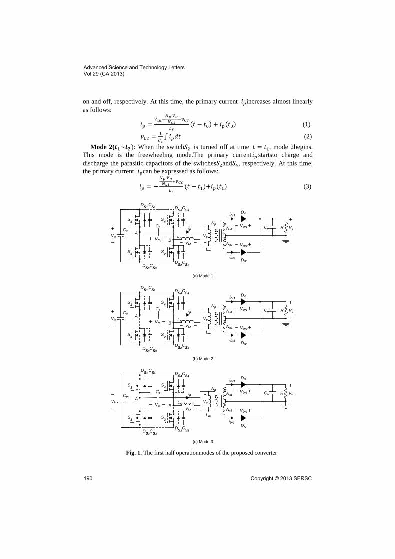
on and off, respectively. At this time, the primary current 𝑖𝑝increases almost linearly as follows:
𝑖𝑝 =𝑉𝑖𝑛−
𝑁𝑝∙𝑉𝑜𝑁𝑠1
−𝑣𝐶𝑐
𝐿𝑟(𝑡 − 𝑡0) + 𝑖𝑝(𝑡0) (1)
𝑣𝐶𝑐 = 1𝐶𝑐∫ 𝑖𝑝𝑑𝑡 (2)
Mode 2(𝒕𝟏~𝒕𝟐): When the switch𝑆2 is turned off at time 𝑡 = 𝑡1, mode 2begins. This mode is the freewheeling mode.The primary current 𝑖𝑝 startsto charge and discharge the parasitic capacitors of the switches𝑆2and𝑆4, respectively. At this time, the primary current 𝑖𝑝can be expressed as follows:
𝑖𝑝 = −𝑁𝑝∙𝑉𝑜𝑁𝑠1
+𝑣𝐶𝑐
𝐿𝑟(𝑡 − 𝑡1)+𝑖𝑝(𝑡1) (3)
Fig. 1. The first half operationmodes of the proposed converter
Vin
Cin
S1 S4
S2S3
DS1CS1 DS4
CS4
DS3CS3
DS2CS2
Cc
VCc
Aip
Lr Vp
Np
Lm
iDr1Dr1
VDr1
Dr2
VDr2
Ns1
Ns2
Co R Vo
VLrB
iDr2
(a) Mode 1
Vin
Cin
S1 S4
S2S3
DS1CS1 DS4
CS4
DS3CS3
DS2CS2
Cc
VCc
Aip
Lr Vp
Np
Lm
iDr1Dr1
VDr1
Dr2
VDr2
Ns1
Ns2
Co R Vo
VLrB
iDr2
(b) Mode 2
Vin
Cin
S1 S4
S2S3
DS1CS1 DS4
CS4
DS3CS3
DS2CS2
Cc
VCc
Aip
Lr Vp
Np
Lm
iDr1Dr1
VDr1
Dr2
VDr2
Ns1
Ns2
Co R Vo
VLrB
iDr2
(c) Mode 3
Advanced Science and Technology Letters Vol.29 (CA 2013)
190 Copyright © 2013 SERSC
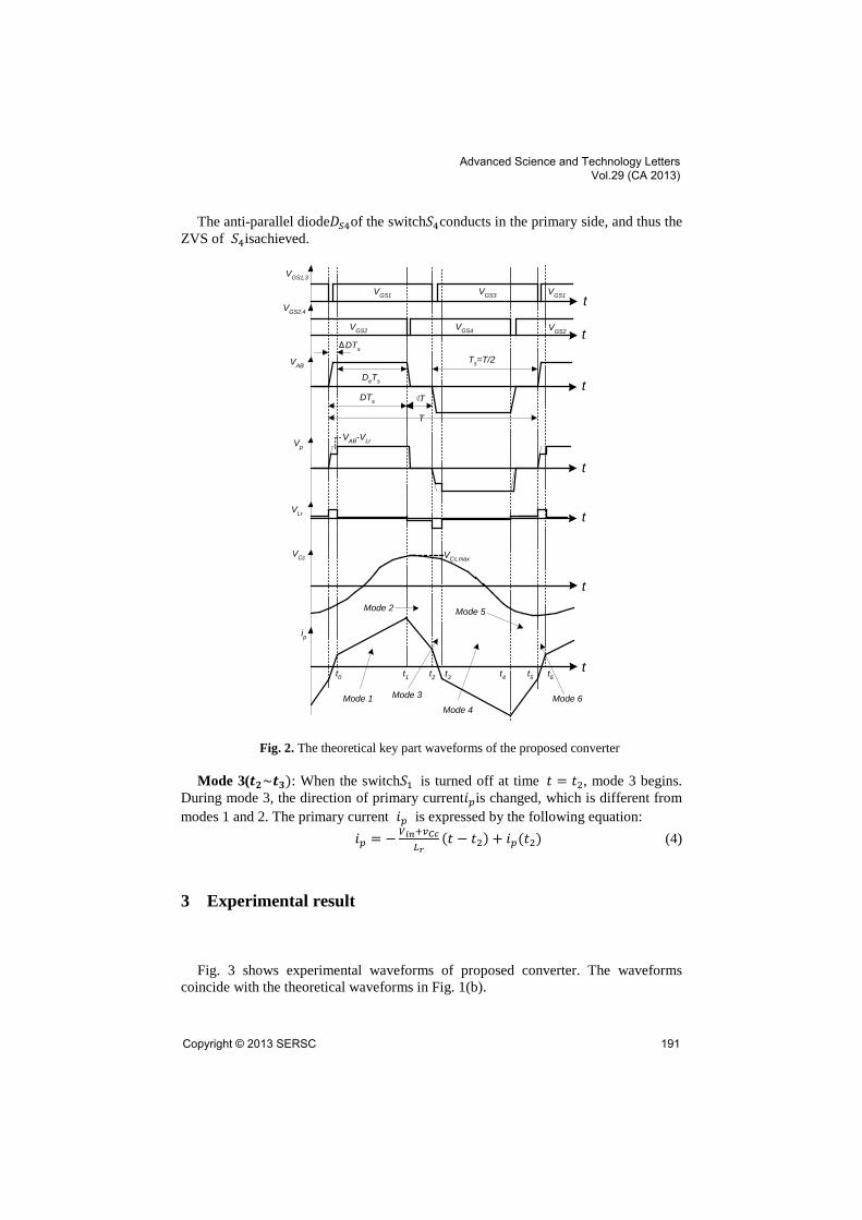
The anti-parallel diode𝐷𝑆4of the switch𝑆4conducts in the primary side, and thus the ZVS of 𝑆4isachieved.
Fig. 2. The theoretical key part waveforms of the proposed converter
Mode 3(𝒕𝟐~𝒕𝟑): When the switch𝑆1 is turned off at time 𝑡 = 𝑡2, mode 3 begins. During mode 3, the direction of primary current𝑖𝑝is changed, which is different from modes 1 and 2. The primary current 𝑖𝑝 is expressed by the following equation:
𝑖𝑝 = − 𝑉𝑖𝑛+𝑣𝐶𝑐𝐿𝑟
(𝑡 − 𝑡2) + 𝑖𝑝(𝑡2) (4)
3 Experimental result
Fig. 3 shows experimental waveforms of proposed converter. The waveforms
coincide with the theoretical waveforms in Fig. 1(b).
DTs
DTs
DeTs
T
T
Ts=T/2
VGS1,3
VGS2,4
VGS1 VGS3
VGS2 VGS4 VGS2
VGS1
VCc,maxVCc
VAB
ip
t
Vp
VLr
VAB-VLr
t0 t1
Mode 1
Mode 2
Mode 3
Mode 4
Mode 5
Mode 6
t2 t3 t4 t5 t6
t
t
t
t
t
t
Advanced Science and Technology Letters Vol.29 (CA 2013)
Copyright © 2013 SERSC 191

(time: 2μs/div.)
Fig. 3. Experimental waveforms of the key parts of the proposed converter
4 Concluding remarks
In this paper,a high power DC-DC converter using the PD PWM technique and
resonant circuit has been proposed, and the operational principle and the experimental result have been described and shown to verify the feasibility of the proposed converter, respectively.
References
1. J. G. Cho, J. W. Baek, C. Y. Jeong, D. W. Yoo,and K. Y. Joe :Novel Zero-Voltage and
Zero-Current-Switching Full Bridge PWM Converter using Transformer Auxiliary Winding, IEEE Trans. on Power Elec., Vol. 15, No. 2, pp. 250-257 (2000)
2. G. B. Koo, G. W. Moon, and M. J. Youn :Analysis and Design of Phase Shift Full Bridge Converter with Series Connected Two Transformers, IEEE Trans. on Power Elec., Vol.19, No. 2, pp. 411-419 (2004)
3. G. B. Koo, G. W. Moon, and M. J. Youn : New Zero-Voltage-Switching Phase-Shift Full-Bridge Converter With Low Conduction Losses, IEEE Trans. on Industrial Electronics, Vol. 52, No. 1, pp. 228-235 (2005)
4. G. Y. Jeong, D. H. Yoo, and M. G. Kim :Simple High-Efficiency Resonant Full-Bridge DC-DC Converter with the Unipolar Pulse-Width Modulation Method,Journal of KIIT. Vol. 11, No. 5 (2013)
Vpip
VLr
Vp ,VLr :200V/div ip :5A/div
Advanced Science and Technology Letters Vol.29 (CA 2013)
192 Copyright © 2013 SERSC