Embed Size (px)
Citation preview

HIGH-PERFORMANCE WIRELESSRECORDING VIDEO
BORESCOPE SYSTEMUSER’S MANUAL
DCS1800
Please read this manual carefully and thoroughly before using this product.

TABLE OF CONTENTS
Introduction . . . . . . . . . . . . . . . . . . . . . . . . . . . . . . . . . 3 – 4
Key Features . . . . . . . . . . . . . . . . . . . . . . . . . . . . . . . . . . . 4
Safety Instructions . . . . . . . . . . . . . . . . . . . . . . . . . . . . . . 5
What’s in the Case . . . . . . . . . . . . . . . . . . . . . . . . . . . . . . 5
Product Overview . . . . . . . . . . . . . . . . . . . . . . . . . . . . . . . 6
Setup Instructions . . . . . . . . . . . . . . . . . . . . . . . . . . . . 7 – 8
Charge Console and Probe Batteries . . . . . . . . 7 – 8
Sync Console and Probe . . . . . . . . . . . . . . . . . . . . 8
Insert SD Card . . . . . . . . . . . . . . . . . . . . . . . . . . . . . 8
Operating Instructions . . . . . . . . . . . . . . . . . . . . . . . 9 – 14
Viewing Live Video on the Console . . . . . . . . 9 – 10
Viewing Live Video on a TV Monitor . . . . . . . . . . . 10
Taking Pictures and Recording Videos . . . . . 10 – 11
Viewing Photos and Playing Back Videos . . . . . . 11
Accessing SD Card Content . . . . . . . . . . . . . 11 – 12
Navigating the Main Menu . . . . . . . . . . . . . . 12 – 14
Attaching a Mirrored Viewing Tip (Optional) . . . . 14
Specifications . . . . . . . . . . . . . . . . . . . . . . . . . . . . . 15 – 16
Operating, Maintenance & Troubleshooting Tips . . . . . . . . . . . . . . . . . . . . . . . . . . . 16
Compatible Probes . . . . . . . . . . . . . . . . . . . . . . . . . . . . . 17
Warranty Information . . . . . . . . . . . . . . . . . . . . . . . . . . . 18
Return for Repair Policy . . . . . . . . . . . . . . . . . . . . . . . . . 18
2
INTRODUCTION
Thank you for purchasing General Tools & Instruments’ (General’s) DCS1800 High-Performance Wireless Recording Video Borescope System. Please read this user’smanual carefully and thoroughly before using the instrument.
The standard DCS1800 system comprises three components:
• The DCS1800 Handheld Wireless Recording Video Borescope Console
• The DCS1800-TR Wireless Probe Handle/Controller
• The P16181SR-M flexible-obedient probe
The DCS1800-TR provides both the connector needed to interface with the P16181SR-Mprobe (or an optional high-performance wired probe from General) and the transmitterneeded to send video captured by the probe to the DCS1800 console. Dozens of thesecompatible high-performance probes are available; a table that lists and describes themcan be found on p. 17.
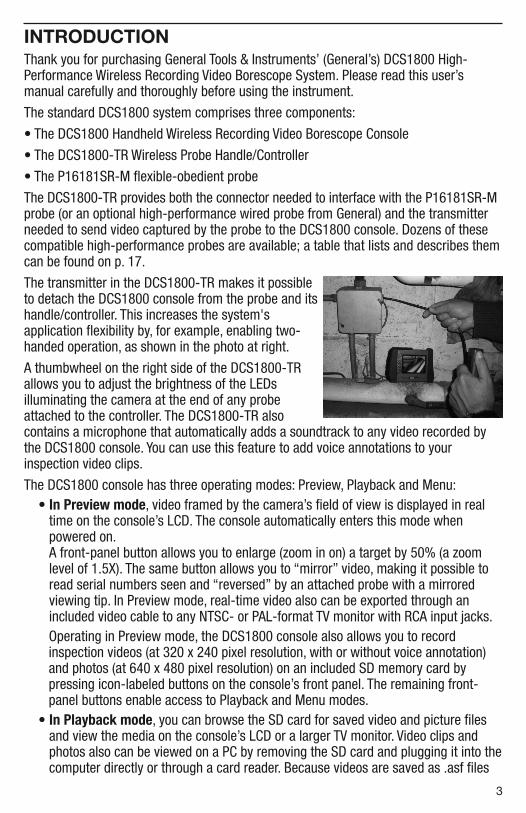
The transmitter in the DCS1800-TR makes it possibleto detach the DCS1800 console from the probe and itshandle/controller. This increases the system'sapplication flexibility by, for example, enabling two-handed operation, as shown in the photo at right.
A thumbwheel on the right side of the DCS1800-TRallows you to adjust the brightness of the LEDsilluminating the camera at the end of any probeattached to the controller. The DCS1800-TR alsocontains a microphone that automatically adds a soundtrack to any video recorded bythe DCS1800 console. You can use this feature to add voice annotations to yourinspection video clips.
The DCS1800 console has three operating modes: Preview, Playback and Menu:• In Preview mode, video framed by the camera’s field of view is displayed in real
time on the console’s LCD. The console automatically enters this mode whenpowered on. A front-panel button allows you to enlarge (zoom in on) a target by 50% (a zoomlevel of 1.5X). The same button allows you to “mirror” video, making it possible toread serial numbers seen and “reversed” by an attached probe with a mirroredviewing tip. In Preview mode, real-time video also can be exported through anincluded video cable to any NTSC- or PAL-format TV monitor with RCA input jacks.Operating in Preview mode, the DCS1800 console also allows you to recordinspection videos (at 320 x 240 pixel resolution, with or without voice annotation)and photos (at 640 x 480 pixel resolution) on an included SD memory card bypressing icon-labeled buttons on the console’s front panel. The remaining front-panel buttons enable access to Playback and Menu modes.
• In Playback mode, you can browse the SD card for saved video and picture filesand view the media on the console’s LCD or a larger TV monitor. Video clips andphotos also can be viewed on a PC by removing the SD card and plugging it into thecomputer directly or through a card reader. Because videos are saved as .asf files
3

and photos as .jpg files, applications found on most PCs (Microsoft Windows MediaPlayer and Microsoft Office Picture Manager) can open the files. The 2GB SDmemory card included in the DCS1800ART case can store at least 5 hours of video,recorded at an average of 6 Mbytes/minute, in addition to hundreds of photos. Tohear the voice annotation (soundtrack) of a video clip, you must play back the clipon a TV monitor or a PC because the DCS1800 console has no speaker.
• In Menu mode, you use familiar scrolling motions and responses to dialog boxes tonavigate a main menu with six submenus. When selected, submenu items execute“housekeeping” functions such as deleting files, setting the date and time, enablingor disabling date and time stamps, choosing any of 14 languages for displayindications, selecting a Video out format and adjusting the console’s Auto Power Offtrigger. One of the submenus has a sub-submenu that allows you to adjust fourattributes (brightness, contrast, hue and saturation) of video viewed on the consoleor an external monitor.
KEY FEATURES
• Standard system includes 1m long, 5.5mm diameter flexible-obedient probe, withcamera lighting provided by four adjustable-brightness white LEDs.
• Operating flexibility is maximized when console is detached from probe. In wirelessmode, video captured by probe can be sent to console from up to 150 ft. (46m)away on any of four channels.
• Console has 3.5 in. diagonal color LCD for viewing probe video in real time and savedvideo clips and pictures later
• Standard system includes three mirrors that attach to the tip of the probe to changeits viewing angle to 70°, 90° or 110°
• A soundtrack is automatically added to every video as it is recorded. To voice-annotate a video, simply speak into the wireless probe handle/controller, whichincludes a microphone.
• Compatible with dozens of high-performance camera-tipped probes from General(see p. 17)
• 14 available menu languages
• Familiar menu-driven user interface for viewing and recording videos and photos onstandard SD memory card (2GB card included) and playing back media on console,TV or PC
• Rechargeable Lithium-ion batteries with 4-hour capacity
• 1-year limited warranty
4

SAFETY INSTRUCTIONS
CAUTION!Never insert any probe attached to the DCS1800 console into any structure or
space known or suspected to contain live electric wiring• The DCS1800 system is intended for industrial applications only. Do not use a
compatible probe for human or any other biological inspections.
• Never insert an attached probe into any flammable gas or liquid (including fuels inan oil, gasoline or diesel tank)
• Do not disassemble the console. Doing so creates a potentially fatal electricalhazard (and voids the warranty as well).
WHAT’S IN THE CASE
The DCS1800ART system comes in a custom hard plastic protective carrying case.Inside the case are:
• The DCS1800 console. The console integrates an LCD monitor, circuitry forwirelessly connecting to a high-performance camera-tipped probe from General,and front-panel controls for controlling the camera’s lights, adjusting systemparameters, and recording and playing back videos and photos captured by anattached probe.
• The P16181SR-M Probe, with a length of 1m (39 in.) and a diameter of 5.5mm(0.22 in.)
• A 2GB SD memory card
• Attachable 70°, 90° and 110° mirrored probe tips
• An AC adapter/battery charger for a 110/220VAC supply. The adapter has a 5.5VDC,center-positive output plug.
• A video cable for connecting the DCS1800 console to a TV monitor. The cable hasRCA plugs at one end and a mini-stereo plug at the other end.
• A small flat-blade screwdriver for changing the wireless channel of the console andprobe
• A soft cloth, a bottle of liquid, and cotton swabs for cleaning the console
• A package of desiccant
• This user’s manual
5

PRODUCT OVERVIEW
Fig. 1 shows the names and locations of all of the controls, ports and jacks of theDCS1800 console. Table 1 details how the function of each front-panel button changeswith the console’s operating mode. Familiarize yourself with the labels, positions andfunctions of all controls and connectors before moving on to the Setup Instructions andOperating Instructions.
Fig. 1. The controls, ports and jacks of the DCS1800 console
Table 1. The DCS1800 console’s multi-function buttonsButton Label In Preview Mode In Playback Mode In Menu Mode
� Switches to Playback mode Selects next-oldest video or photo Moves up one line
� Switches to Playback mode Selects next-newest video or photo Moves down one line
OK/Menu Switches to Menu mode Offers option to delete selected Executes highlighted video or photo `command
Esc Presssed briefly, enlarges Switches to Preview mode Switches to Preview target by 50% (zooms 1.5X) modePressed and held, mirrors video
Takes a picture Recalls next photo or Displays repair data or (stores .jpg photo on SD card) pauses/plays video clip opens submenu of video
attribute options
Starts/stops recording an Switches to Preview mode Switches to Preview mode.asf video on SD card
6
1 Start/Stop Video RecordingButton
2 Snapshot Button3 Power On/Off Button4 Previous Video/Photo Button5 � Next Video/Photo Button
6 OK/Menu Enter/Save/EnterMenu mode Button
7 Esc Escape/Zoom/Mirror Button8 SD Card Socket9 TV Out Jack10 AC Adapter Jack
(1) (2)
(3)
(4)(5)(6)(7)
(8)
(9)
(10)

SETUP INSTRUCTIONSCHARGE CONSOLE AND PROBE BATTERIESTo prepare to power the system on for the first time,securely attach the DCS1800-TR Wireless ProbeHandle/Controller (with probe attached) to the back ofthe DCS1800 console using the two motions shown atright. Plug one end of the supplied AC adapter/batterycharger into a wall socket. Then swing the black rubberprotective flap away from the right side of the DCS1800console to expose the AC adapter jack (Fig. 1, Callout10). Insert the cylindrical plug at the end of theadapter/charger cable into the AC adapter jack. This will begin charging the console’s battery and theDCS1800-TR's battery at the same time. Next, power on the probe by rotating the probecontroller’s thumbwheel downward until you feel and hear a click.
Table 2. Correlating the color of the LED on the DCS1800-TR probehandle/controller with battery charge
LED COLOR BATTERY STATUS COMMENT
Green ln use Working under full battery
Dark Red Low battery Recharge battery when dark red light appears during usage
Oranqe Charging while in use Charging while in use
Red Charging with power off Charging with power off
None Full battery with power off Light dims whenbattery is fully charged
Next, press the red the button on the console (Fig. 1, Callout 3) and hold it for at leastfive seconds. The LCD will illuminate and briefly show the word CAMERA on the left andan icon indicating the charge of the console's battery on the right (both in green),superimposed on video being captured in real time by the camera at the end of the probe.
Practice using the thumbwheel on the probe controller to adjust the intensity of thecamera’s lighting. In a brightly lit room, moving the thumbwheel has a big effect on thebrightness of the LEDs at the tip of the probe, but a much smaller effect on thebrightness of video on the screen. The on-screen impact of changing brightness is morepronounced in dark environments.
To power off the DCS1800 console, push the button and hold it for at least five seconds.
It will take several hours to fully charge the console and DCS1800-TR batteries the firsttime. You cannot replace either battery, which can only be replaced by General-authorized service personnel. Do not open the case of either component in anattempt to change the battery yourself. Doing so creates a potentially fatal electricalhazard (and voids the warranty as well) with the AC adapter plugged in.
7

With proper care (charging the batteries often, and never allowing them to completelydischarge), you can expect each battery to last four or five years. Fully charged batteriesshould power at least four hours of operation.
SYNC CONSOLE AND PROBEIt's important to realize that the DCS1800 console is now showing video only becausethe DCS1800-TR is physically attached to it. For most inspection applications, you willwant to detach the probe handle/controller from the console and use its built-intransmitter to send video to the console's LCD wirelessly. Detaching the twocomponents frees up both of your hands. You can then use one hand to feed the probeinto the area you want to inspect, and the other to hold the probe handle in the bestposition for adjusting camera lighting and/or voice-annotating videos (see p. 9).
The DCS1800 console and the DCS1800-TR probe handle/controller can communicatewirelessly only if both components are operating on the same channel. Four channelscentered on 2.4GHz are available. Both components may have already been set to the same channel at the factory. To discover whether that is the case, detach theDCS1800-TR from the console. If the console's LCD resumes showing probe video aftera brief delay, the two units are already operating on the same channel and there is noneed to sync them.
If detaching the DCS1800-TR from the console causes the video to disappear, leavingstatic on the screen, you must sync the two components.
To synchronize the transmitting frequency of the probe handle with the receivingchannel of the console, you can either change the channel of the DCS1800-TR or thechannel of the console. In either case, you will use the small flat-blade screwdriverincluded in the case. The channel selector switch of the console is on the rear of theunit, in the center near the top. The channel selector switch of the probe controller isalso on the back of the unit.
Since there are only four available channels, the fastest way to sync the twocomponents is to use the screwdriver to move the channel selector switch of eithercomponent through all four of its possible positions. When probe video appears on theconsole, you have succeeded in syncing the two units.
INSERT SD CARDThis final setup step enables storage of video clips and photos. Remove the supplied2GB SD memory card from its packaging. Discard the packaging, but save the plasticstorage case.
Push the SD card into the socket on the right side of the console (Fig. 1, Callout 8). Besure the card’s gold contacts are facing front and enter the socket first. Push in the carduntil you feel it spring back and you hear a click.
Note that when you inserted the SD card, a new icon with four bars appeared briefly onthe bottom right of the console's LCD. This icon indicates the used capacity of thememory card. Four green bars indicate a full SD card. No green bars indicate an emptycard.
To remove the card later, push it in gently until you hear a click and the card pops out farenough for your fingers to grab.
8
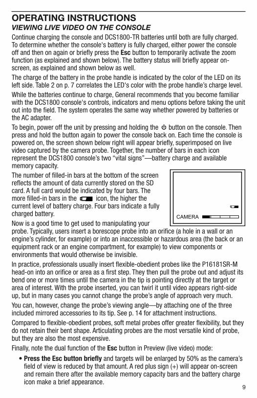
OPERATING INSTRUCTIONSVIEWING LIVE VIDEO ON THE CONSOLEContinue charging the console and DCS1800-TR batteries until both are fully charged. To determine whether the console's battery is fully charged, either power the console off and then on again or briefly press the Esc button to temporarily activate the zoomfunction (as explained and shown below). The battery status will briefly appear on-screen, as explained and shown below as well.The charge of the battery in the probe handle is indicated by the color of the LED on itsleft side. Table 2 on p. 7 correlates the LED's color with the probe handle’s charge level. While the batteries continue to charge, General recommends that you become familiarwith the DCS1800 console's controls, indicators and menu options before taking the unitout into the field. The system operates the same way whether powered by batteries orthe AC adapter.To begin, power off the unit by pressing and holding the button on the console. Thenpress and hold the button again to power the console back on. Each time the console ispowered on, the screen shown below right will appear briefly, superimposed on livevideo captured by the camera probe. Together, the number of bars in each iconrepresent the DCS1800 console’s two “vital signs”—battery charge and availablememory capacity.The number of filled-in bars at the bottom of the screenreflects the amount of data currently stored on the SDcard. A full card would be indicated by four bars. Themore filled-in bars in the icon, the higher thecurrent level of battery charge. Four bars indicate a fully charged battery.Now is a good time to get used to manipulating yourprobe. Typically, users insert a borescope probe into an orifice (a hole in a wall or anengine’s cylinder, for example) or into an inaccessible or hazardous area (the back or anequipment rack or an engine compartment, for example) to view components orenvironments that would otherwise be invisible.In practice, professionals usually insert flexible-obedient probes like the P16181SR-Mhead-on into an orifice or area as a first step. They then pull the probe out and adjust itsbend one or more times until the camera in the tip is pointing directly at the target orarea of interest. With the probe inserted, you can twirl it until video appears right-sideup, but in many cases you cannot change the probe’s angle of approach very much.You can, however, change the probe’s viewing angle—by attaching one of the threeincluded mirrored accessories to its tip. See p. 14 for attachment instructions.Compared to flexible-obedient probes, soft metal probes offer greater flexibility, but theydo not retain their bent shape. Articulating probes are the most versatile kind of probe,but they are also the most expensive.Finally, note the dual function of the Esc button in Preview (live video) mode:
• Press the Esc button briefly and targets will be enlarged by 50% as the camera’sfield of view is reduced by that amount. A red plus sign (+) will appear on-screenand remain there after the available memory capacity bars and the battery chargeicon make a brief appearance.
9

• Press and hold the Esc buttonand video will be mirroredhorizontally, as shown in the twophotos at right. The effect makesit possible to read text or serialnumbers “reversed” by anattached probe with a mirroredviewing tip—by undoing thereversal. A red “M” will appear on-screen to indicate that video is being mirrored.
You can mirror and zoom videos at the same time by pressing the Esc button briefly, andthen pressing and holding the button. In this case, a red M and a red plus sign willappear on-screen together.
VIEWING LIVE VIDEO ON A TV MONITORYour DCS1800 system comes with a video cable for connecting the console to a TV or TVmonitor that uses either the NTSC or PAL analog broadcast standard. By making theconnection, you can view live video (or saved videos and pictures) on a screen largerthan the console’s.
To implement the connection in hardware, insert the stereo mini-plug of the providedcable into the TV Out jack of the console (Fig. 1, Callout 9). Then insert the yellow RCAplug at the other end of the cable into the Video In jack of your TV or TV monitor, leavingthe white RCA plug unconnected. Be sure to set the TV input to external video.
Real-time videos shown on an external monitor can be enlarged by pressing the Escbutton. But videos cannot be mirrored, as they can when viewed on the console’s LCD.
To activate the connection in software and begin exporting console’s video to a TV, referto the instructions for the VIDEO FORMAT and AV OUTPUT lines in the “Navigating theMain Menu” section of this manual, beginning on p. 12.
TAKING PICTURES AND RECORDING VIDEOSTo take a picture, make sure the console is in Preview mode (with live video appearingon the LCD) and press the button. Doing so creates a .jpg file of the frame beingdisplayed at that moment and stores it on the SD card. A red icon briefly appears atthe lower left of the LCD to confirm that a picture was taken. The console automaticallyreturns to Preview mode after taking a picture.
To record a video, make sure the console is in Preview mode and press the button.Doing so begins creating an.asf video file (with MPEG-4 compression) for storage on theSD card. A red icon appears at the lower left of the screen to confirm that a recordingis in progress, and it remains there for the duration of the video. To stop recording, pressthe button again. This makes the red icon disappear and returns the console toPreview mode.
While a video is being recorded, all console buttons other than the and buttonsare disabled. Pressing the button takes a picture, stops recording video and returnsthe console to Preview mode.
10

The console will be unable to store videos and pictures if its SD memory card is full,write-protected or damaged. When the instrument senses any of these conditions, it willsuperimpose the word FULL on the screen in Preview mode. To remedy the situation,either replace the full SD card by another card with spare capacity, or delete filesindividually or in bulk. Instructions for deleting files can be found later in this user’smanual.
VIEWING PHOTOS AND PLAYING BACK VIDEOSTo view a picture or play back a video on the console’s LCD or a TV monitor, switch theunit out of Preview mode and into Playback mode by pressing the � or � button (Fig.1, Callouts 4 and 5, respectively). In Playback mode, pressing the � button repeatedlyrecalls all photos and videos from memory in the reverse order in which they werecreated and stored (in other words, the newest first and the oldest last). Each press ofthe � button selects the next oldest picture or video. Videos begin playing automatically.A green icon and a red icon are superimposed on the video at the lower left ofthe screen. After a photo has been on-screen for 60 seconds, the console automaticallyswitches to Preview mode.
Pressing the button while a video is playing pauses playback and replaces the red icon with a red icon. Pressing the button again resumes play and restores the red icon. Pressing the button while a video is playing switches to Preview mode.Pressing the button while a picture is being displayed selects the next newest file.
To listen to the voice annotation (soundtrack) of any recorded video clip, you mustplay it back on a TV monitor or a PC because the DCS1800 console lacks a speaker.
To implement the playback connection on a TV monitor, insert the stereo mini-plug of theprovided video cable into the TV Out jack of the console (Fig. 1, Callout 9). Then insertthe yellow RCA plug at the other end of the cable into the Video In jack of the TV or TVmonitor, and the white RCA plug into the Left (L) or Right (R) Audio In jack. Be sure to setthe TV input to external video.
While each photo and video is on-screen, pressing the OK/Menu button gives you theoption to delete its file. Pressing the button calls up a dialog box with the word DELETEabove the flashing word NO. Pressing the � or � button changes the flashing word toYES. When the correct answer (for you) appears, press the OK/Menu button to choosethat action.
ACCESSING SD CARD CONTENTPhotos and videos stored on the SD card also can be viewed on a PC. If your computerhas an SD card slot, you can eject the memory card from the console and plug it directlyinto a PC. If your PC does not have an SD card slot, you can purchase a USB SD cardreader (Part No. SDRD1) from General.
If you choose to remove the SD card from the console and plug it into a PC, eitherdirectly or through a card reader, remember to eject the card from the PC once you aredone viewing (and/or copying) the files it contains. Depending on your PC’s startupsettings, your computer may fail to restart following its next shutdown if the SD cardremains inserted. The PC’s operating system may try to reboot from the SD card and beunable to do so.
11

Details of the SD card’s file structure are worth mentioning because assigned file namescontain useful information. The figure below illustrates the hierarchy. It shows that theSD card contains one folder named “DCIM” and one subfolder named “100MEDIA”. The100MEDIA folder contains all stored photo and video files, identified by their .JPG and.ASF extensions. You should not rename the DCIM and 100MEDIA folders while theSD card is inside your PC. If you rename either folder, the console will fail torecognize the SD card the next time you plug it in.
The 8-digit file names identify the date and time when the file was created. The first twodigits represent the month and day, and the last six digits represent the hour, minute andsecond. For example, the upper file name shown above identifies a photo file that wascreated on January 1 at 06:14:23 a.m. The lower file name identifies a video file thatwas created on the same day at 06:14:35 a.m.
The console’s file-naming convention uses the letters A through C to represent themonths October through December, and the letters A through V to represent days of themonth from 10 through 31. For example, a file created on October 11 would begin withthe letters AB (A for 10 and B for 11). As another example, a file created on November30 would begin with the letters BU (B for 11 and U for 30.
Finally, the file-naming convention uses military (24-hour) time. For example, a namewith the last six digits 142531 would indicate a file created at 02:25:31 p.m.
NAVIGATING THE MAIN MENUThe main menu of the DCS1800 console provides access to the following housekeepingand operational functions:
• Bulk file erasure
• Video exporting
• Setting the date and time
• Choosing a display language
• Selecting a TV format and adjusting video atrtributes
• Enabling/disabling and adjusting the Auto Power Off function
Menu mode has a hierarchical structure and uses prompts and dialog boxes familiar toanyone who has used an Automated Teller Machine (ATM). The only constraint on using themenu is your own response speed. If no selection is made within 10 seconds followingentry into Menu mode, the console will automatically revert to Preview mode. Thesame time constraint applies to selections within submenus. If you do not respond to a prompt (indicated by a flashingword or line of text) within 10 seconds, the console willswitch back to Preview mode—its default operating state.
To access the main menu, press the OK/Menu button to enterMenu mode. Doing so brings up the screen shown at right.
12
DELETE ALL FILES AV OUTPUTDATE/TIMELANGUAGETV SYSTEMAUTO POWER OFF
MAIN MENU
To navigate the main menu, use the � and � buttons to move up and down until theparameter you wish to change is highlighted and flashing in green. Then push theOK/Menu button to select it and call up its submenu.
The DELETE ALL FILES line gives you two options (yes and no) that can be selectedusing the � and � buttons. The sequence is similar to the previously describedprocedure for deleting an individual photo or video.
The AV OUTPUT line allows you to send the real-time video stream shown on thedisplay unit out through the unit’s TV out jack to an NTSC or PAL TV monitor. Theconsole's display will turn black until you select this option again. Before activating thisfunction, make the physical connection described in the “Viewing Live Video on a TVMonitor” section.
The DATE/TIME SETUP line allows you to set the console's calendar and clock. Doing sois necessary only if you wish to keep track of your photo and video files by date and time.
When DATE/TIME SETUP is selected, the screen that appears has the year flashing ingreen. To increase the value, press the button. To decrease the value, press thebutton. Once you have set the year, advance to the next field—the month—by pressingthe � button. Set the month as you did the year, by using the � and � buttons toincrease or decrease the value by one unit per button press. Repeat this process until allsix date and time components have been set. To back up from any field to the previousfield, press the � button.
The bottom line of the DATE/TIME SETUP screen also allows you to choose whether ornot to superimpose the date and time on the display in Preview mode. The defaultcondition is “display off”, meaning the date and time are not displayed. To alwayssuperimpose the date and time, navigate down to the bottom line until the word OFFbelow the word DISPLAY is flashing in green. Then push either the or button tochange the flashing word to ON. Finally, press the OK/Menu button to save the setting.
The LANGUAGE line of the main menu allows you to view the main menu, as well as theDELETE screens for individual photos and videos, in any of 14 languages (English,Spanish, Italian, French, German, Portuguese, Traditional Chinese, Simpified Chinese,Japanese, Danish, Dutch, Polish, Russian and Bulgarian). Use the � and � buttons tonavigate to the language you wish to use and then push the OK/Menu button.
The VIDEO FORMAT line enables you to choose either NTSC or PAL formatting of thevideos you export to a TV monitor. Press either the � and � button to make your choiceand then push the OK/Menu button to save the setting.
Pressing the button with either NTSC or PAL flashing on the VIDEO FORMATsubmenu opens a sub-submenu with the following lines: Brightness, Contrast, Hue andSaturation. You can use this submenu to change any of those four video attributes fromthe default factory settings.
The default factory settings are: 00 for Brightness, 40 for Contrast, 00 for Hue, and 50for Saturation. To change the value of any attribute, navigate to its line and press theOK/Menu button when its name begins flashing in green. The screen will then go darkexcept for the name of the attribute at the top. To increment the value from the factorydefault value, press the � button (the opposite of what you’d expect). To decrement thevalue, press the � button (again, the opposite of what you’d expect).
13

There are 256 options for the value of each video attribute, and the attributes areidentified and ordered by hexadecimal (base 16) numbers. For example, pressing the � button to increment the value 09 produces 0A (the number 10 in base 16 notation);further increments yield 0B through 0F (the numbers 11 through 15). Incrementing 0Fproduces the value 10 (the number 16 in hexadecimal notation). Similarly, incrementing19 produces the value 1A; further increments yield 1B through 1F. Incrementing 9Fproduces A0, further increments produce A1 through A9, and further increments produceAA through AF. Incrementing AF produces BA, and so on, through FF (the number 255 inhexadecimal notation). Incrementing FF completes the cycle, producing a value of 00.
The AUTO POWER OFF line of the main menu is not visible on the screen that firstappears after you press the OK/Menu button to put the console into Menu mode. Toshow the line, scroll down past the VIDEO FORMAT line. When the AUTO POWER OFFline appears, flashing in green, press the OK/Menu button.
By default, the AUTO POWER OFF function of the console is disabled. To enable it, and tochoose how quickly to power off the instrument following a period of inactivity, navigateto one of the four options (5, 10, 15 or 30 minutes) and press the OK/Menu button. Tore-disable the function later, enter Menu mode, scroll down to the AUTO POWER OFFline, press the OK/Menu button, select DISABLE and press the OK/Menu button againto save the setting.
ATTACHING A MIRRORED VIEWING TIP (OPTIONAL)The DCS1800 system includes three mirrored viewing tips that screw onto the end ofthe supplied probe or any other compatible probe. To attach any of these tips:
1. Pull off the probe’s rubber protective cap.
2. Unscrew and remove the black metal thread protector ring, as shown below at left.
3. Remove the blue circular protective film from the mirrored viewing tip by pulling onits tab.
4. Screw the viewing tip onto the camera head by turning it clockwise, as shownbelow at right. Keep turning until the tip can travel no further.
5. After using and removing the mirrored viewing tip, remember to reinstall the blackmetal thread protector ring by screwing it onto the camera head.
14

SPECIFICATIONSDCS1800 CONSOLE
Display Type Color TFT LCD
Display Size 3.5 in (89mm) diagonal
Display Resolution 320 by 240 pixels (QVGA)
Video Recording Resolution 320 x 240 pixels (QVGA)
Video File Format .asf
Photo Recording Resolution 640 x 480 pixels (VGA)
Photo File Format .jpg
Video Out Formats NTSC, PAL
Video Frame Rate 30 frames per second (fps)
Receiving Frequencies 2.414GHz, 2.432GHz, 2.450GHz,2.468GHz
Compression Format Compatible with MPEG4
Signal-to-Noise Ratio 42dB or greater
Recording Medium Standard-size SD card
Interfaces AV Out, USB 2.0
Languages English, Spanish, Italian, French, German, Portuguese, Traditional Chinese, Simpified Chinese, Japanese, Danish,Dutch, Polish, Russian, Bulgarian
Power Source Rechargeable 3.7V Li-ion battery
Power Consumption 1.8A @ 5.5VDC
Operating Temperature -4° to 140°F (-20° to 60°C)
Storage Temperature -4° to 140°F (-20° to 60°C)
Recharge Temperature 32° to 104°F (0° to 40°C)
Console Dimensions 8.5 x 4.7x 1.4 in. (215 x 120 x 36mm)
Console Weight 13.4 oz (380g)
15

P16181SR-M FLEXIBLE-OBEDIENT PROBE
Length 1m (3.28 ft)
Diameter 5.5mm (0.22 in.)
Depth of Field 0.4 to 12 in. (10 to 300mm)
Field of View 46° (horizontal), 34° (vertical), 56° (diagonal)
Resistances To water, oil & dust per IP67 standard
Camera Lighting 4 white LEDs
OPERATING, MAINTENANCE & TROUBLESHOOTING TIPS
• Never remove the SD card while taking a picture or recording a video. Doing so maydamage the card and erase or corrupt the photo or video.
• If the LCD remains or goes dark, the first two things to confirm are that the consoleand probe batteries are adequately charged, and that both components areoperating on the same channel.
• If live video begins to look spotty, streaky or intermittent, the likely reason is anunder-charged battery. Plug in the AC adapter/battery charger immediately.
• Video recording requires an SD card with a fast writing speed. For maximum videoquality, General recommends SD cards with a writing speed of 80X or higher.
• Avoid using corrosive liquids such as alcohol to clean either the LCD or the camerahead. To clean the camera lens and LEDs, use a cotton swab and a small amount ofcleaning solution. To clean the LCD, use the provided cloth, cotton swabs and liquid.To clean the plastic housings of the console and probe controller, use a soft, drycloth.
• Operate and store the console, probe handle and probe only in a cool (under 140ºFor 60ºC), dry, well-ventilated place. Avoid exposing either unit to sunlight for longperiods of time.
• To avoid damaging the console, use only compatible probes and accessories.
• The P16181SR-M probe is flexible to make it easy for you to inspect hard-to-reachareas. Never insert or bend it by force, and never over-bend any part of the probe.Specifically:
• Do not bend the last 1 to 2 in. of theprobe by more than 70°
• Do not bend the probe at any otherpoint by more than 90°
16
1 to 2 in. (25 to 50mm) from tip
2 in. (50mm) or more from tip

COMPATIBLE PROBESThe table below describes and compares all probes compatible with the DCS1800system console.Model No. (SKU) Probe Description UPC Camera Head Diameter Probe Length Depth of Field
P16ART-1SM Metal 01418 9 1m (3.28 ft.)
P16ART-2SM 01476 9 2m (6.6 ft.)
P16ART-3SM 01500 1 3m (9.8 ft.)
P16HPART VGA Resolution 01579 9 1m (3.28 ft.)Articulating Probe
P16181SR-M 01408 0 1m (3.28 ft.)
P16182SR-M 01409 7 2m (6.6 ft.)
P16183SR-M 01410 3 3m (9.8 ft.)
P16181SM-M 01411 0 1m (3.28 ft.)
P16183SM-M 01412 7 3m (9.8 ft.)
P16185SM-M 01414 4 5m (16 ft.)
P161810SM-M 01414 1 10m (32 ft.)
P161830SM-M 01415 8 30m (98 ft.)
P1839-M 01424 0 1m (3.28 ft.)
P16182-39 01556 8 2m (6.6 ft.)
P16183-39 01557 5 3m (9.8 ft.)
P1618FS-49 01481 3 1m (3.28 ft.)
P16182-49 01554 4 2m (6.6 ft.)
P16183-49 01553 7 3m (9.8 ft.)
P16181HP VGA Resolution Probe 01576 6 1m (3.28 ft.) 0.4 to 12 in. (10 to 300mm)
P1618SV-1SM Side View Soft 01407 3 1m (3.28 ft.)Metal Probe
P1618SV-1SR Side View Flexible- 01406 6 1m (3.28 ft.)Obedient Probe
P16PIP Pipe & Duct Inspection 01578 0 28mm (1.1 in.) 22m (72 ft.) 0.4 in. (10mm) Probe & Reel Set to infinity
17
Soft MetalArticulating Probe
6mm (0.23 in.)
0.25 to 6 in. (6.4 to 150mm)
0.25 to 6 in. (6.4 to 150mm)
0.4 to 12 in. (10 to 300mm)
3.9mm (0.15 in)
4.9mm (0.19 in)
5.5mm (0.22 in.)
5.5mm (0.22 in.)
Flexible-ObedientProbe
Ultra-Slim Flexible-Obedient Probe
Switchable Front/Side View Flexible-Obedient Probe
Soft Metal Probe
WARRANTY INFORMATION
General Tools & Instruments’ (General’s) DCS1800 High-Performance Wireless RecordingVideo Borescope System is warranted to the original purchaser to be free from defectsin material and workmanship for a period of one year. Subject to certain restrictions,General will repair or replace this instrument if, after examination, the companydetermines it to be defective in material or workmanship.
This warranty does not apply to damages that General determines to be from anattempted repair by non-authorized personnel or misuse, alterations, normal wear andtear, or accidental damage. The defective unit must be returned to General Tools &Instruments or to a General-authorized service center, freight prepaid and insured.
Acceptance of the exclusive repair and replacement remedies described herein is acondition of the contract for purchase of this product. In no event shall General be liablefor any incidental, special, consequential or punitive damages, or for any cost, attorneys’fees, expenses, or losses alleged to be a consequence of damage due to failure of, ordefect in any product including, but not limited to, any claims for loss of profits.
RETURN FOR REPAIR POLICYEvery effort has been made to provide you with a reliable product of superior quality.However, in the event your instrument requires repair, please contact our CustomerService to obtain an RGA (Return Goods Authorization) number before forwarding theunit via prepaid freight to the attention of our Service Center at this address:
General Tools & Instruments80 White StreetNew York, NY 10013212-431-6100
Remember to include a copy of your proof of purchase, your return address, and yourphone number and/or e-mail address.
18

NOTES
________________________________________________________________
________________________________________________________________
________________________________________________________________
________________________________________________________________
________________________________________________________________
________________________________________________________________
________________________________________________________________
________________________________________________________________
________________________________________________________________
________________________________________________________________
________________________________________________________________
________________________________________________________________
________________________________________________________________
________________________________________________________________
________________________________________________________________
________________________________________________________________
________________________________________________________________
________________________________________________________________
________________________________________________________________
________________________________________________________________
________________________________________________________________
________________________________________________________________
________________________________________________________________
19

GENERAL TOOLS & INSTRUMENTS80 White Street
New York, NY 10013-3567PHONE (212) 431-6100 FAX (212) 431-6499
TOLL FREE (800) 697-8665e-mail: [email protected]
www.generaltools.com
DCS1800 User’s Manual
Specifications subject to change without notice
©2012 GENERAL TOOLS & INSTRUMENTS
NOTICE - WE ARE NOT RESPONSIBLE FOR TYPOGRAPHICAL ERRORS.
MAN#DCS1800 07/12/12