Embed Size (px)
Citation preview

11 12
GD200A Series General Purpose Vector Control Drive Product IntroductionGD200A series high performance general vector inverter, positioned as a new
generation general purpose inverter; products using DSP control system and vector
V/F control technology, with excellent motor drive performance and various protecting
functions, widely used in air compressor, plastic machine, petroleum industry, coal
industry, HVAC applications, fan pump and other standard transmission load.
Product Advantage● High performance● Multi-function with simple operation ● Reliable quality certificated
High Performance
More Accurate Motor Autotuning
Advanced open loop vector control
Perfect voltage and current control, reducing the fault protection times
Multiple braking modes and instant stopping
OC fault
Dynamic braking
Flux braking
OV fault
DC braking
Short circuit braking
Accurate rotating and static motor autotuning Convenient debugging and easy operation
The current, torque and rotating speed waveforms when sudden loading or unloading in asynchronous motor open loop vector control mode with 0.5Hz running frequency and full load.
Adjust the output frequency to avoid overcurrent of the inverter during acceleration
● Configure braking units and resistors● Available on the situation of big inertia load and frequent braking● Big braking torque and quick braking
● No need to configure braking units and resistors● Available on the instant stopping situation with big inertia load and no frequent bra king● Not available on the situation of big inertia load and frequent and braking(the energy consumed on the stator and its cooling is better than DC braking)
● No need to configure braking units and resistors● Available on the situation when start the running motor after braking and the situation when keep the moment output after braking to zero speed● Not available on the situation of big inertia load or instant stopping braking in high speed running
● No need to configure braking units and resistors, capable of braking quickly● Applicable to the motors at quick start and stop or restart after braking● Not applicable to big inertia load and frequent braking
Adjust the output frequency to avoid overvoltage of the DC bus during deceleration
Rotating autotuning Static autotuning
De-couple form the loadApplied to the situation with high control accuracy
No need to de-couple from the load Applied when rotating autotuning is not available
Current Torque & Rotating speed
GD20&GD200A Series Vector General
General Purpose Vector Drive

13 14
Multi-Function with Simple Operation
Separate Air-duct
The rivet design ensures reliable integration connection
Standard built-in C3 input filters, optional external C2 filters
GD200A series
Multiple installation modes
Smaller Size
Book structure
High Performance KeypadThe separate air duct prevents the contaminants into the electronic parts/components and greatly improves the protective effect of the inverter, as well as its reliability and service life, to adapt various complicated site environments. It can also facilitate the heat-releasing in control cabinets and the heat-releasing design of the customer.
Greener Proper groundingStronger corrosion-resistance Excellent EMC performance
Remarks: C2 filter: EMC performance of the inverter achieves the limited usage requirement in civil environment.C3 filter: EMC performance of the inverter achieves the limited usage requirement in civil environment.
0.75~200kW: Wall mounting and flange mounting200~315kW: Wall mounting and floor mounting 350~500kW: Floor mounting
Due to the thermal simulation and advanced modularized design, the size of our product is reduced greatly. The width ratio between Goodrive300 and CHF100A is shown in the figure below (the Max. percentage is 50%)
Parallel installationSmaller installation space with less cost and beautiful appearance.C3 input filter is embedded in the factory to meet different
application requirements,save installation space and avoid electromagnetic interference caused by incorrect selection and site installation.
External LED keypads are standard for inverters (≥18.5kW) to support parameters upload and download, the maximum external length is 200M and the keypads have digital potentiometers; external keypads are optional for inverters (≤15kW).
The optional external LCD keypad supports parameters loading and unloading with English.
External keypad LCD keypad
Membrane keypad design (which can be connected to external keypads) is available for inverters (≤15kW); swappable keypads are standard for inverters (≥18.5kW)
Terminals Quantity Features
ON-OFF input 8 channels 1KHz NPN and PNP
High speed 0.75 9.3
Pulse input 1 channel 50KHz NPN and PNP
Analog input 2 channels 0~10V,0~20mA, -10V~+10V
ON-OFF output 1 channel Max. output frequentcy:1KHz
High speed 1.5 5.0
Pulse output 1 channel Max. output frequentcy:50KHz
Analog output 2 channels 0~10V,0~20mA
Relay output 2 channels 3A/250DAC, 1A/30VDC, NO+NC
Remark: above power ratings are subject to G type machine.
Embedded braking units of 0.75-30kW inverters
Supporting common DC bus
Reduce the occupied space and decrease the costsign of the customer.
Reduce the power lost on DBRNote the impact current and the capacity of the input AC system
Available on DC power supply
Function of water supply
Reduce the occupied space and decrease the costsign of the customer.
In the diagram above, M2 and M3 are auxiliary motors which are controlled by RO1 and RO2. PID constant-pressure automatic control system is formed by the inverter through pressure feedback. The pressure reference can apply analog or keypad input. 485 remote communications is also supported.
The product design follows IEC national standards and passes the CE test certification.
Remarks: Each Goodrive200A inverter has past the test certification
GD20&GD200A Series Vector General
General Purpose Vector Drive
15 16
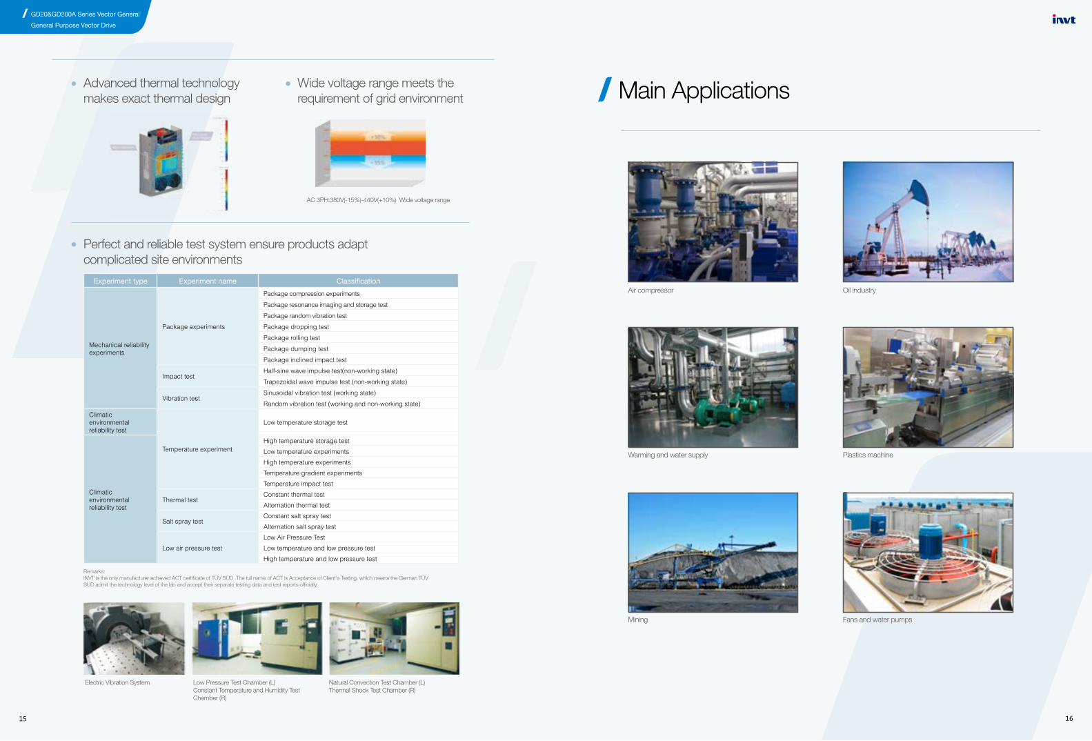
Advanced thermal technology makes exact thermal design
Wide voltage range meets the requirement of grid environment
AC 3PH:380V(-15%)-440V(+10%) Wide voltage range
Perfect and reliable test system ensure products adapt complicated site environments
Electric Vibration System Low Pressure Test Chamber (L)Constant Temperature and Humidity Test Chamber (R)
Natural Convection Test Chamber (L)Thermal Shock Test Chamber (R)
Experiment type Experiment name Classification
Mechanical reliability experiments
Package experiments
Package compression experiments
Package resonance imaging and storage test
Package random vibration test
Package dropping test
Package rolling test
Package dumping test
Package inclined impact test
Impact test Half-sine wave impulse test(non-working state)
Trapezoidal wave impulse test (non-working state)
Vibration test Sinusoidal vibration test (working state)
Random vibration test (working and non-working state)
Climatic environmental reliability test
Temperature experiment
Low temperature storage test
Climatic environmental reliability test
High temperature storage test
Low temperature experiments
High temperature experiments
Temperature gradient experiments
Temperature impact test
Thermal test Constant thermal test
Alternation thermal test
Salt spray testConstant salt spray test
Alternation salt spray test
Low air pressure test
Low Air Pressure Test
Low temperature and low pressure test
High temperature and low pressure test
Remarks: INVT is the only manufacturer achieved ACT certificate of TÜV SÜD .The full name of ACT is Acceptance of Client's Testing, which means the German TÜV SÜD admit the technology level of the lab and accept their separate testing data and test reports officially.
Main Applications
Air compressor
Warming and water supply
Mining
Oil industry
Plastics machine
Fans and water pumps
GD20&GD200A Series Vector General
General Purpose Vector Drive
17 18
Function Illustration
Input
Input voltage (V) AC 3PH 400V±15%
Input current (A) Refer to the rated value
Input frequency (Hz) 50Hz or 60HzAllowed range: 47~63Hz
Output Output voltage (V) 0~input voltage
Output frequency (Hz) 0~400Hz
Technical control feature
Control mode V/F
Motor type Asynchronous motor
Speed ratio Asynchronous motor 1:100
Overload capability
G type:150% of rated current: 1 minute180% of rated current: 10 seconds200% of rated current: 1 second P type:120% of rated current: 60 second
Torque overload capacity
G type:150% for machines180 % for quick response machinesP type:120% for pump and fan
Running control feature
Frequency setting
Digital setting, analog setting, pulse frequency setting, multi-step speed running setting, simple PLC setting, PID setting, MODBUS communication setting, PROFIBUS communication setting.Realize the shifting between the set combination and set channel.
Auto voltage adjustment Keep a stable voltage automatically when the grid voltage transients
Fault protection Provide over 30 fault protection functions: overcurrent, overvoltage, undervoltage, overheating, phase loss and overload, etc.
Speed tracking Restart the rotating motor smoothly
Peripheral interface
Terminal analog input resolution ≤10mV
Terminal switch input resolution ≤ 2ms
Analog input 2 channels (AI1, AI2) 0~10V/0~20mA and 1 channel (AI3) -10~10V
Analog output 2 channels (AO1, AO2) 0~10V /0~20mA
Digital input 8 channels common input, the Max. frequency: 1kHz1 channel high speed input, the Max. frequency: 50kHz
Digital output 1 channel high speed pulse output, the Max. frequency: 50kHz;1 channel Y terminal open collector pole output
Relay output
2 channels programmable relay outputRO1A NO, RO1B NC, RO1C common terminal RO2A NO, RO2B NC, RO2C common terminalContactor capability: 3A/AC250V,1A/DC30V
Others
Mountable method Wall, flange and floor mountable
Temperature of the running environment -10~50℃, derate above 40℃
Ingress protection IP20
Cooling Air-cooling
Braking unit Built-in braking unit for below 30G/37P (including 30G/37P)External braking unit for others
Braking resister External braking
EMC filter Optional built-in C3 filter: meet the degree requirement of IEC61800-3 C3Optional external filter ,meet the degree requirement of IEC61800-3 C2
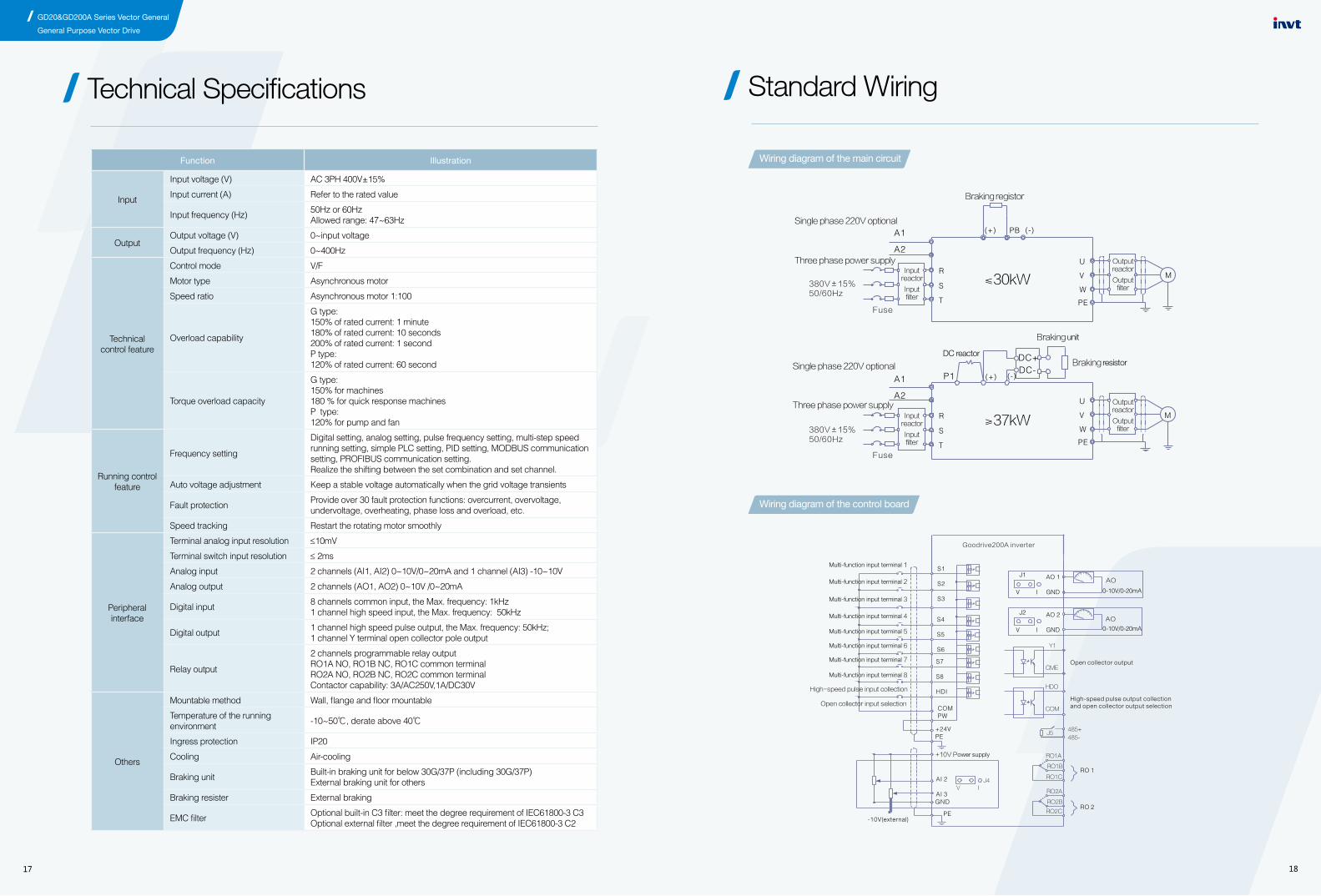
Technical Specifications Standard Wiring
Wiring diagram of the main circuit
Wiring diagram of the control board
GD20&GD200A Series Vector General
General Purpose Vector Drive
Type Selection
Power ratings And Dimension
19 20
Inverter model Rated output power
(kW)Input current
(A)Rated output current
(A)Gross weight
(Kg)Dimension
(mm)
3-phase 220VAC±15%
GD200A-0R75G-2 0.75 5 4.5
4.1kg 360x250x265GD200A-1R5G-2 1.5 7.7 7
GD200A-2R2G-2 2.2 11 10
GD200A-004G-2 3.7 17 16
7.4kg 445x295x320GD200A-5R5G-2 5.5 21 20
GD200A-7R5G-2 7.5 31 30
GD200A-011G-2 11 43 4211kg 550x375x375
GD200A-015G-2 15 56 55
GD200A-018G-2 18.5 71 70
32kg 695x410x470GD200A-022GP-2 22 81 80
GD200A-030G-2 30 112 110
GD200A-037G-2 37 132 130
67kg 760x445x580GD200A-045G-2 45 163 160
GD200A-055G-2 55 181 190
3-phase 380VAC±15%
GD200A-0R75G-4 0.75 3.4 2.5
2.5kg 275 x205 x235GD200A-1R5G-4 1.5 5.0 3.7
GD200A-2R2G-4 2.2 5.8 5
GD200A-004G/5R5P-4 4/5.5 13.5/19.5 9.5/144.1kg 360 x250 x265
GD200A-5R5G/7R5P-4 5.5/7.5 19.5/25 14/18.5
GD200A-7R5G/011P-4 7.5/11 25/32 18.5/25
7.4kg 445 x295 x320GD200A-011G/015P-4 11/15 32/40 25/32
GD200A-015G/018P-4 15/18.5 40/47 32/38
GD200A-018G/022P-4 18.5/22 47/56 38/45 9kg 460 x340 x330
GD200A-022G/030P-4 22/30 56/56 45/6011kg 550 x375x375
GD200A-030G/037P-4 30/37 70/80 60/75
GD200A-037G/045P-4 37/45 80/94 75/92
32kg 695 x410x470 GD200A-045G/055P-4 45/55 94/128 92/115
GD200A-055G/075P-4 55/75 128/160 115/150
GD200A-075G/090P-4 75/90 160/190 150/180
67kg 760 x445 x580 GD200A-090G/110P-4 90/110 190/225 180/215
GD200A-110G/132P-4 110/132 225/265 215/260
GD200A-132G/160P-4 132/160 265/310 260/305
110kg 971 x631 x565 GD200A-160G/200P-4 160/200 310/385 305/380
GD200A-200G/220P-4 200/220 385/430 380/425
GD200A-220G/250P-4 220/250 430/485 425/480
165kg 1086x826x595GD200A-250G/280P-4 250/280 485/545 480/530
GD200A-280G/315P-4 280/315 545/610 530/600
GD200A-315G/350P-4 315/350 610/625 600/650
GD200A-350G/400P-4 350/400 625/715 650/720
450kg 1850x840x820GD200A-400G-4 400 715 720
GD200A-500G-4 500 890 860
Remarks: (1)The input current of the inverter 0.75G-315G/350P is tested when the input voltage is 380V and there is no DC reactor and output/input reactor.(2)The current of the inverter 350G/400P-500G is tested when the input voltage is 380V and there is input reactor.(3)Rated output current is defined when the rated output voltage is 380V.
Installation Dimension
Installation dimension when wall mounting
Installation dimension when flange mounting
Installation dimension when floor mounting
Model W1 W2 H1 H2 D1 Installation holes
3-phase 220VAC Series
0.75kW~2.2kW 146 131 256 243.5 181 6
4kW~7.5kW 170 151 320 303.5 216 6
11kW~15kW 255 237 407 384 245 7
18.5kW ~30kW 270 130 555 540 325 7
37kW~55kW 325 200 680 661 365 9.5
3-phase 380VAC Series
0.75kW~2.2kW 126 115 186 175 174.5 5
4kW~5.5kW 146 131 256 243.5 181 6
7.5kW~15kW 170 151 320 303.5 216 6
18.5kW 230 210 342 311 216 6
22kW~30kW 255 237 407 384 245 7
37kW~55kW 270 130 555 540 325 7
75kW~110kW 325 200 680 661 365 9.5
132kW~200kW 500 180 870 850 360 11
220kW~315kW 680 230 960 926 379.5 13
Inverter model W1 W1 W3 W4 H1 H2 H3 H4 D1 D2Installation
holes
3-phase 220VAC series
0.75kW~2.2kW 170.2 131 150 9.5 292 276 260 6 167 84.5 6
4kW~7.5kW 191.2 151 174 11.5 370 351 324 15 196.3 113 6
11kW~15kW 275 237 259 11 445 426 404 10 245 119 7
18.5kW ~30kW 270 130 261 11 445 426 404 10 245 119 7
37kW~55kW 325 200 317 58.5 680 661 626 23 363 182 9.5
3-phase 380VAC series
0.75kW~2.2kW 150.2 115 130 7.5 234 220 190 13.5 155 65.5 5
4kW~5.5kW 170.2 131 150 9.5 292 276 260 6 167 84.5 6
7.5kW~15kW 191.2 151 174 11.5 370 351 324 15 196.3 113 6
18.5kW 250 210 234 12 375 356 334 10 216 108 6
22kW~30kW 275 237 259 11 445 426 404 10 245 119 7
37kW~55kW 270 130 261 11 445 426 404 10 245 119 7
75kW~110kW 325 200 317 58.5 680 661 626 23 363 182 9.5
132kW~200kW 500 180 480 60 870 850 796 37 358 178.5 11
Inverter model W1 W1 W3 W4 H1 H2 D1 D2Installation
holes
220kW~315W 750 230 714 680 1410 1390 380 150 13\12
350kW~500kW 620 230 553 - 1700 1678 560 240 22\12
Installation dimension (unit: mm)
Installation dimension (unit: mm)
Installation dimension (unit: mm)
GD20&GD200A Series Vector General
General Purpose Vector Drive

21
Installation Diagram
3-phase 220VAC Series Wall Mounting for 0.75-55kW Inverters
0.75-7.5kW Installation diagram
11-15kW Installation diagram
18-55kW Installation diagram
37-110kW Wall mountingInstallation diagram
132-200kW Wall mounting Installation diagram
220-350kW Wall mounting Installation diagram
3-phase 380VAC SeriesWall Mounting for 0.75-315kW Inverters
0.75-15kW Wall mounting Installation diagram
18.5-30kW Wall mounting Installation diagram
3-phase 220VAC Series Flange Mounting for 0.75-55kW Inverters
0.75-7.5kW Flange mounting installation diagram
18-55KW Flange mounting installation diagram
11-15kW Flange mounting installation diagram
3-phase 380VAC SeriesFlange Mounting for 0.75-200kW Inverters
0.75-15kW Flange mounting Installation diagram
Floor Mounting for 200-500kW Inverters
220-315KW Floor mounting Installation diagram
350-500KW Floor mounting Installation diagram
18.5-30kW Flange mounting Installation diagram
37-110kW Flange mounting Installation diagram
132-200kW Flange mounting Installation diagram
Dimension for Keyboard
22
GD20&GD200A Series Vector General
General Purpose Vector Drive

23
Optional Parts
Flange Mounting Panel
Installation bracket for the keypad
LCD keypad
Installation Base
Heat-releasing Hole
AC single-phase 220V input auxiliary power supply
Needed for 0.75G-30G//37P inverters.Not needed for 37G/40P-200G//220P inverters.
Installation bracket or M3 screw can be used in the installation of external keypad.The bracket of 0.75G-30G//37P inverters is standard.The bracket of 37G/40P-500G inverters is optional
10 rows of DH displayingCompatible with the LED keypad
Only optional in 220G/250P-315G/350P inverters .Its bases can be built in an input AC (or DC) reactor or an output AC rector
Inverter needs to derate when selecting a cover Consult with the INVT technicians for the detailed information.
For more convenient debugging
24
ReactorThe inverters of 37G/45P and above can be connected with external DC reactor. The reactor can improve the power factor and avoid damage to the recitifier bridge caused by overcurrent and damage to the rectifier circuit by harmonic
Inverter model Input reactor DC reactor Output reactor
GD200A-0R7G-4 ACL2-1R5-4 / OCL2-1R5-4
GD200A-1R5G-4 ACL2-1R5-4 / OCL2-1R5-4
GD200A-2R2G-4 ACL2-2R2-4 / OCL2-2R2-4
GD200A-004G/5R5P-4 ACL2-004-4 / OCL2-004-4
GD200A-5R5G/7R5P-4 ACL2-5R5-4 / OCL2-5R5-4
GD200A-7R5G/011P-4 ACL2-7R5-4 / OCL2-7R5-4
GD200A-011G/015P-4 ACL2-011-4 / OCL2-011-4
GD200A-015G/018P-4 ACL2-015-4 / OCL2-015-4
GD200A-018G/022P-4 ACL2-018-4 / OCL2-018-4
GD200A-022G/030P-4 ACL2-022-4 / OCL2-022-4
GD200A-030G/037P-4 ACL2-030-4 / OCL2-030-4
GD200A-037G/045P-4 ACL2-037-4 DCL2-037-4 OCL2-037-4
GD200A-045G/055P-4 ACL2-045-4 DCL2-045-4 OCL2-045-4
GD200A-055G/075P-4 ACL2-055-4 DCL2-055-4 OCL2-055-4
GD200A-075G/090P-4 ACL2-075-4 DCL2-075-4 OCL2-075-4
GD200A-090G/110P-4 ACL2-090-4 DCL2-090-4 OCL2-090-4
GD200A-110G/132P-4 ACL2-110-4 DCL2-110-4 OCL2-110-4
GD200A-132G/160P-4 ACL2-132-4 DCL2-132-4 OCL2-132-4
GD200A-160G/185P-4 ACL2-160-4 DCL2-160-4 OCL2-160-4
GD200A-185G/200P-4 ACL2-200-4 DCL2-200-4 OCL2-200-4
GD200A-200G/220P-4 ACL2-200-4 DCL2-200-4 OCL2-200-4
GD200A-220G/250P-4 ACL2-250-4 DCL2-250-4 OCL2-250-4
GD200A-250G/280P-4 ACL2-250-4 DCL2-250-4 OCL2-250-4
GD200A-280G/315P-4 ACL2-280-4 DCL2-280-4 OCL2-280-4
GD200A-315G/350P-4 ACL2-315-4 DCL2-315-4 OCL2-315-4
GD200A-350G/400P-4 standard configuration DCL2-350-4 OCL2-350-4
GD200A-400G-4 standard configuration DCL2-400-4 OCL2-400-4
GD200A-500G-4 standard configuration DCL2-500-4 OCL2-500-4
GD20&GD200A Series Vector General
General Purpose Vector Drive
Filters
Inverter model input filter output filter
GD200A 3-phase 380VACSeries
G:0.7—2.2KW FLT-P04006L-B FLT-L04006L-B
G:4—5.5KWP:5.5—7.5KW FLT-P04016L-B FLT-L04016L-B
G:7.5—11KW P:11—15KW FLT-P04032L-B FLT-L04032L-B
G:15—18KW P:18—22KW FLT-P04045L-B FLT-L04045L-B
G:22—30KW P:30—37KW FLT-P04065L-B FLT-L04065L-B
G:37—45KW P:45—55KW FLT-P04100L-B FLT-L04100L-B
G:55—75KW P:75—90KW FLT-P04150L-B FLT-L04150L-B
G:90KW P:110KW FLT-P04200L-B FLT-L04200L-B
G:110—132KW P:132—160KW FLT-P04250L-B FLT-L04250L-B
G:160—200KW P:185—220KW FLT-P04400L-B FLT-L04400L-B
G:220—280KW P:250—315KW FLT-P04600L-B FLT-L04600L-B
G:315—400KW P:350—400KW FLT-P04800L-B FLT-L04800L-B
G:500KW FLT-P041000L-B FLT-L041000L-B
Remarks: C2 standard can be achieved of select above external filters

25 26
Braking system
Inverter model braking unit model
100%braking torque fit braking
resisters(Ω)
power of braking
resister(kW)(10% braking
count)
power of braking
resister(kW)(50% braking
count)
power of braking
resister(kW)(80% braking
count)
allowing minimum braking
resister(Ω)
GD200A-0R7G-4
built-in braking unit
653 0.1 0.6 0.9 240
GD200A-1R5G-4 326 0.23 1.1 1.8 170
GD200A-2R2G-4 222 0.33 1.7 2.6 130
GD200A-004G/5R5P-4 122 0.6 3 4.8 80
GD200A-5R5G/7R5P-4 89 0.75 4.1 6.6 60
GD200A-7R5G/011P-4 65 1.1 5.6 9 47
GD200A-011G/015P-4 44 1.7 8.3 13.2 31
GD200A-015G/018P-4 32 2 11 18 23
GD200A-018G/022P-4 27 3 14 22 19
GD200A-022G/030P-4 22 3 17 26 17
GD200A-030G/037P-4 16 5 23 36 17
GD200A-037G/045P-4 DBU100H-060-4 13 6 28 44 11.7
GD200A-045G/055P-4
DBU100H-110-4
10 7 34 54
6.4GD200A-055G/075P-4 8 8 41 66
GD200A-075G/090P-4 6.5 11 56 90
GD200A-090G/110P-4DBU100H-160-4
5.4 14 68 1084.4
GD200A-110G/132P-4 4.5 17 83 132
GD200A-132G/160P-4 DBU100H-220-4 3.7 20 99 158 3.2
GD200A-160G/185P-4
DBU100H-320-4
3.1 24 120 192
2.2GD200A-185G/200P-4 2.8 28 139 222
GD200A-200G/220P-4 2.5 30 150 240
GD200A-220G/250P-4DBU100H-400-4
2.2 33 165 2641.8
GD200A-250G/280P-4 2.0 38 188 300
GD200A-280G/315P-4
TwoDBU100H-320-4
3.6*2 21*2 105*2 168*2
2.2*2GD200A-315G/350P-4 3.2*2 24*2 118*2 189*2
GD200A-350G/400P-4 2.8*2 27*2 132*2 210*2
GD200A-400G-4 TwoDBU100H-400-4
2.4*2 30*2 150*2 240*21.8*2
GD200A-500G-4 2*2 38*2 186*2 300*2
The power of 30G/37P(including) for GD200A inverters built-in barking unit, and 37G/45P(including) inverters need external braking unit; please choosing the resister and power of braking resister for site situation(require of braking torque and amount).Braking resister can increase braking torque of inverter , In the table it designs the resister power according to 100%braking torque,10%braking count,50% braking count,80% braking count; and customers can choose braking system according to specific process and work condition.
GD20&GD200A Series Vector General
General Purpose Vector Drive


![Wunner arXiv:1310.3046v1 [quant-ph] 11 Oct 2013 ...itp1.uni-stuttgart.de/institut/arbeitsgruppen/main/1310.3046v1.pdf · Dipolar Bose-Einstein condensates in triple-well potentials](https://img.dokumen.tips/doc/110x75/5c6c236a09d3f262278c24e0/wunner-arxiv13103046v1-quant-ph-11-oct-2013-itp1uni-dipolar-bose-einstein.jpg)


