Embed Size (px)
Citation preview

High Performance Horizontal Machining Center
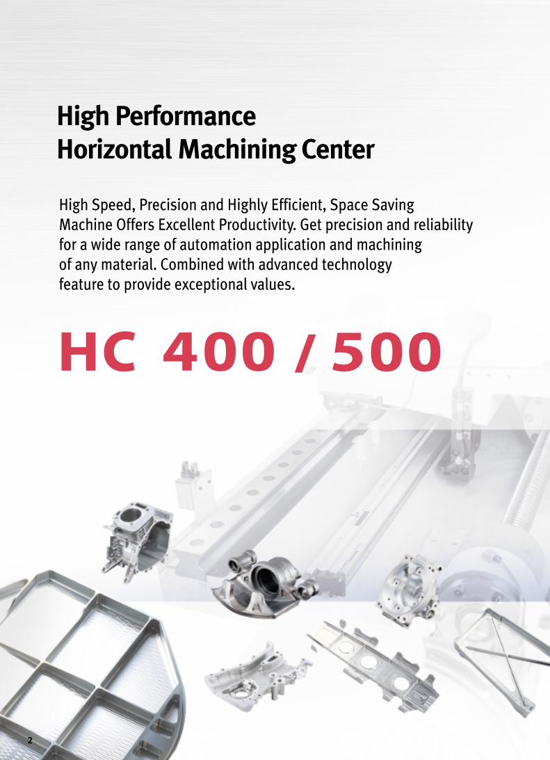
High Speed, Precision and Highly Efficient, Space Saving
Machine Offers Excellent Productivity. Get precision and reliability
for a wide range of automation application and machining
of any material. Combined with advanced technology
feature to provide exceptional values.
High Performance
Horizontal Machining Center
2

3

High Speed Spindle
● HC 400 Standard 8000r/min (11/18.5kW)
■Spindle power-torque diagram
The high speed 8000 r/min 40 taper spindle isa true cartridge type unit supported by fourprecision class P4 high speed bearings whichare permanently greased and lubricated. Thespindle is driven by a high torque 18.5 kWA.C. motor delivering an impressive 235.5 N.mon HC 400.
OOiill ccoooolleerr
A refrigerated spindle coolingsystem circulates cooling oil tomaintain a constant temperature forhigh accuracy, regardless of theambient temperature or cuttingconditions.
Powerful high-speed and precision.
(15min)(15min)(30min)(30min)
(cont.) (cont.)
SPINDLE SPEED (r/min)
TORQUE(N.m)
POWER(kW)
0 750 60008000
235.5191.0140.0
29.423.8
14.313.010.8
30
18.515
119
● HC 400 Option 10000r/min (22/26kW)
(30min)(30min)
(cont.)(cont.)
SPINDLE SPEED (r/min)
TORQUE(N.m)
POWER(kW)
1500 6000100000
165.5
15.212.4
140.2
30
26
22
16
13
● HC 500 Standard 8000r/min (11/18.5kW)
(5min)
(5m
in)
(15min)
(15m
in)
(15min)(30min) (30min)(cont.)
(cont.)
SPINDLE SPEED (r/min)
TORQUE(N.m)
POWER(kW)
500620
7501000
40006000
80000
353.4286.5235.3191.2143.2
29.423.517.612.710.7
40
18.5151197.5
● HC 500 Option 10000r/min (22/26kW)
SPINDLE SPEED (r/min)
TORQUE(N.m)
POWER(kW)
(30min)
(30min)
(cont.) (cont.
)
10001500
40006000
100000
20.924.8
52.562.0
140.2165.5
302622
1613
4
1188..55 kkWW{26 kW}
88000000 rr//mmiinn{10000 r/min}
MMaaxx.. ssppiinnddllee ssppeeeedd MMoottoorr ((1155mmiinn))
223355..55 NN..mm (15 min) HC 400
335533..44 NN..mm (5 min) HC 500{ } : Option
MMaaxx.. ssppiinnddllee ttoorrqquuee

5
The ATC is composed of tool magazine and change arm. Thetools are selected by a fixed address method that follows theshorter path. All tools are returned to the pots from which theywere originally taken so that collision problems involving large-sized tools need to be considered only once when they are firstmounted.
•Tool driving mechanism- Servo type
11..55 ss (T-T-T)
TTooooll cchhaannggee ttiimmee
4400 ttoooollss {Opt:60/120/170/262}
TTooooll ssttoorraaggee ccaappaacciittyy
Sophisticated mechanisms drastically reduce non-cutting time.
AAuuttoommaattiicc ttooooll cchhaannggeerr
Tool Magazine

6
The possibility that chips might degrade the meshing accuracy of the palletpositioning mechanism increases at higher machining speeds. On the HC 400and HC 500 strong jets of air are discharged from the tapered cones when apallet is changed to clean any chips from the cones and assure accuratepallet positioning.
Automatic Pallet Changer
D mm
H m
mMMaaxx.. WWoorrkkppiieeccee SSiizzee..
HC 400 and HC 500 is equipped with rotary shuttle type APC (AutomaticPallet Changer) as a standard feature. It provides high reliability and wideworking area for easy setup. The pallet changer is rigidly built and operateswith the opening and closing of the splash guard to accomplish palletchanges in 8.0 seconds.
Pallet change time
88..00 ss (HC 400)
88..55 ss (HC 500)
HHCC 440000 HHCC 550000
PPaalllleett ssiizzee 400×400mm 500×500mm
MMaaxx..wwoorrkkppiieeccee ssiizzee Ø600×H 800mm Ø800×H 900mm
MMaaxx..wwoorrkkppiieeccee wweeiigghhtt 400 kg 500 kg

7
The machine is designed to build rigidity into a stable body. Theconstruction of the machine was thoroughly examined from the stage ofbasic design to ensure consistent high-speed and high-accuracyoperation. The deformation of the bed when subject to a load at thecenter was simulated to secure high level rigidity against bending. TheHC 400 and HC 500 have an design with a basic structure using FEMadvanced technology.
Rigid structure bed and column
TTrraavveell aaxxeess ((XX//YY//ZZ))
RRaappiidd ttrraavveerrssee
HC 400 660000//556600//556655 mmmm
HC 500 885500//770000//775500 mmmm
HC 400 4400 mm//mmiimm
HC 500 4400 mm//mmiimm
The feed mechanism adopts heavy duty linear motion rollerguideways that provide superior acceleration/decelerationperformance to reduce non-cutting time.
Guideways and Axis Drives
HC Series with oversized AC servo drives power through the toughestcuts in the toughest metal. The high torque servos are coupled directlyto the ball screws. With no gears there is no risk of backlash or servodrag.

Chip Disposal
Interface for Fixture
FFiixxttuurree cchheecckk lliisstt (for hydraulic/pneumatic fixtures)
NNuummbbeerr ooff PPoorrttss
2*1×2*2 Line
2*1×3*2 Line
2*1×4*2 Line
2*1×6*2 Line
2*1×8*2 Line
*1 : Pallet No. 1 and No. 2(Number of Pallet)
*2 : Number of port line
HHyyddrraauulliicc ppoowweerr uunniitt
Special requirement
L/min at MPa
Contact Doosan Infracore for more information
8
Hinge type
Scraper type
Drum filter type
Separate chipconveyor and
coolant tank provide easy cleaning andmaintenance. A telescopic cover, inclined at a
30。angle, directs chips into the chip sliding cover tokeep the area around the table clean. From the sliding
cover, chips are flushed onto the chip conveyor by the screwconveyors to make quick and easy work of chip removal.
Chip conveyor (Option)
×○○
○×○
×△○
×○○
• ○:Available ×:Unavailable △:Asking for information• Some types of chips may not be completely removed from the chip conveyor.• Contact Doosan for more information.
Steel Cast Aluminum andnonferrous metals
Specifications
Compound
Hinge type
Scraper type
Drum filter type

9
Ergonomic and Eco-Friendly Design EEaassyy sseettuupp
Less waste lubrication oil extends the life time ofthe coolant water and cut down the grime andoffensive smell of the machine inside.
CCoolllleeccttiioonn ooff wwaassttee lluubbrriiccaattiioonn ooiill
DDiissttaannccee ttoo ttaabbllee
HHeeiigghhtt ttoo ttaabbllee
Rigorously designed, manufactured and testedmachine covers do not permit coolant leakage inany condition. The factory always keeps ourenvironment clean.
NNoo ccoooollaanntt lleeaakkaaggee
OOiill sskkiimmmmeerr ((oopptt..))
Another suggestion to prolongthe life time of the coolantwater. A belt-driven type oilskimmer picks up and removeswaste oil from the coolant tankthat is easily drained.
AAddjjuussttttaabbllee tthhiinn ooppeerraattoorr′′ss ppaanneell
HC 400 338800 mmmm
HC 500 550000 mmmm
HC 400 11113300 mmmm
HC 500 11116600 mmmm

HHCC 550000
Flexible Multi Pallet System
TTooooll mmaaggaazziinneeNumerous Variations to meet production efficiency needs.
894 mm
60-tool (opt.)
973 mm
120-tool (opt.)
2,158 mm
170-tool (opt.)
HHCC 550000
unit : mm
Application technology of Multi-pallet system is
the best solution for the high productivity in the
machining shop.
AApppplliiccaattiioonn ooff mmuullttii ppaalllleett ssyysstteemm
Name HC 500 (2 sets)
Number of Setup Station 1Storage Capacity (500×500) 18 cells
■ 7-Station Round Type Multi Pallet Magazine
■High Productivity & availability■Flexible production solutions■High efficiency system■Compact designed technology■Easy to extend stations
(7,9,11,13st)
10

FFaaccee mmiillll Carbon steel (SM45C)
Ø80 Face mill (5Z)
DDrriillll Gray casting (GC25)
Ø37 Drill (2Z)
TTaapp Gray casting (GC25)
Ø38.5 Drill (2Z)
53mm
3mm37mm
53mm
3mm
48mm
7mm60mm
53mm
3mm37mm37mm
48mm
7mm60mm
53mm
3mm37mm
48mm
7mm60mm
FFaaccee mmiillll Aluminum
Ø80 Face mill (5Z)
DDrriillll Gray casting (GC25)
Ø49 Drill (2Z)
TTaapp Gray casting (GC25)
53mm
3mm37mm
48mm
7mm60mm
48mm
7mm
53mm
3mm37mm
48mm
7mm60mm60mm
53mm
3mm37mm
48mm
7mm60mm
Machining rate
Spindle speed Feedrate
Feedrate
Spindle speed
Tool
Spindle speed Feedrate
Cutting Performance
225500 rr//mmiinn
338800 cm3/min 221100 mm/min
11550000 rr//mmiinn 11220000 mmmm//mmiinn
MM3300××PP33..55
332200 rr//mmiinn 11112200 mmmm//mmiinn
Machining rate
Spindle speed Feedrate
Feedrate
Spindle speed
Tool
Spindle speed Feedrate
110000 mm/min
112255 rr//mmiinn
22331188 cm3/min
22339900 rr//mmiinn 66990000 mmmm//mmiinn
MM3300××PP33..55
332200 rr//mmiinn 11112200 mmmm//mmiinn
11
Guarantees high-productivity and high-accuracy in a variety of machining operations

Standard Features
Flood coolant Operator call lamp (red/yellow/green)
FANUC 21i-MB controller Portable MPG
Work light APC operator's panel
Rigid tapping Oil cooler
Screw conveyor
12
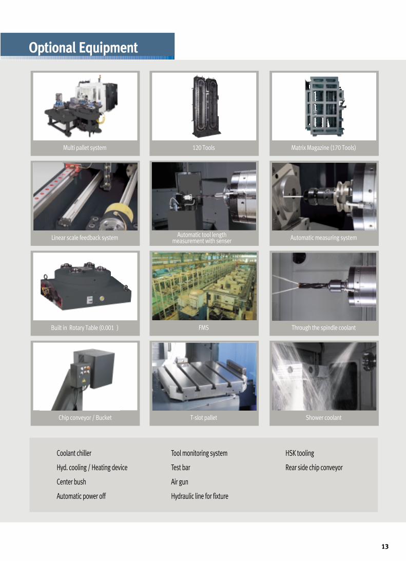
Multi pallet system 120 Tools Matrix Magazine (170 Tools)
Linear scale feedback system Automatic measuring systemAutomatic tool length measurement with senser
Built in Rotary Table (0.001。) FMS Through the spindle coolant
Chip conveyor / Bucket T-slot pallet Shower coolant
• Coolant chiller
•Hyd. cooling / Heating device
• Center bush
• Automatic power off
• Tool monitoring system
• Test bar
• Air gun
•Hydraulic line for fixture
•HSK tooling
• Rear side chip conveyor
Optional Equipment
13

■High compact CNC is realized through LCD display with integrated CNC and a flash memory card interface is standard features.■Provides many support functions for set-ups, such as tool measurement, workpiece measurement at the original point, and workpiece
measurement inside the machine.■Uses one display screen to perform all operations including programming,
checking by animation, and real machining.■User-Friendly Operation : Soft key Selection of Comprehensive Cycle Library
SSttaannddaarrdd FFeeaattuurreess
Easy Operating System
Guide for machining preparationIn preparation for machining, simple instructions on aselected screen allow to measure the setting error ofworkpiece and tool offset value for automatedadjustment.
14

Tool Monitoring System (Opt.)
■For machining center, turning center and compound machine with milling andturning.
■Solid modeling provides high speed animation. (TFT-LCD Color Only)
■Icon menu soft-keys provide convenient programming for sophisticated milling and turning.
■Measurement cycles provide automatic offset measurement of workpiece (Available for machining center and for compound machine).
■Registration of parameter sets for high speed machining and/or for highprecision machining with machine configurations.
■Instruction of precision level for desired machining selects appropriate
parameters automatically.
■Precision level can be instructed through NC program.
Easy operation system
One single screen provides handy operation guidance forprogramming through machine operation.
One single screen provides convenient operation ¶meter setting for high speed and high precisionmachining instructions.
Machining condition selecting function
TTooooll llooaadd mmoonniittoorriinngg ssyysstteemm TTooooll mmaannaaggeemmeenntt ffuunnccttiioonnTool Monitoring System is one of safety
functions to protect Tool and Spindle against
a possible damage of abnoraml load caused
by tool wear and breakage or others. This
system montitors the tool status during
machine operation by detecting the abnormal
load of exch axis and spindle.
•The screen shows a tool and pallet No.,
load meter of each axis and spindle limit
load.
•This functions consisted of tool pre-check
function, substitutive tool selection with
tool life management and different tool &
port number command function.
15

unit : mm
External Dimensions
16
(425)4135(4560)
685
2250
620
613.
513
12
270
80
2335
102
2822
290
1771
274
2335
2822
2335
(425)42084560 524
1621
5263 (285)
2064
460
156
2680
(544
)
(474
)
(785
)(6
30)
(409
5)
(5548)
Ø80
0Ø18
80
Ø800
ST.750
ST.
850
ST.
700
540 540
2165
375
2540
4971 (365) (390)(5336)
(5726)
2538
1160
(460
)
Max
. Wor
kpie
ce H
eigh
t90
0
Front View
Top View
Side View
Front View
Top View
Side View

unit : mm
unit : mm
Pallet Dimensions
Tool Shank
17
HOLE FOR M16
5010010010010050
24-M16X2 TAP,DP30
36
18
25
7575
500
500
5010
010
010
010
050
15 °
TAPER GAGE LINE
17Ø
14Ø
19Ø
44.4
5Ø
63.5
5Ø
50Ø
17Ø
11.1
15.9 3.2 68.4
35
M16xP2.0
22.825
204
2
23Ø
30°
7Ø
HO
LE
7/24 TAPER
M16xP2.0
7Ø
72.3
Ø
16.118
.5
18.5
2628
60 °
22.8 25
16.1
63.5
5Ø
56.2
5Ø
7.07
11.1
44.4
5Ø
"T"
7/24 TAPER
TAPER GAGE LINE
60。
17Ø
23Ø
"T" 15 °
14Ø
28 26
17Ø
204
2
19Ø
30°
68.43515.92 3.18
7Ø
HO
LE
44.7
Ø
Std : BT40 Opt. : DIN 40
Opt. : CAT 40
18
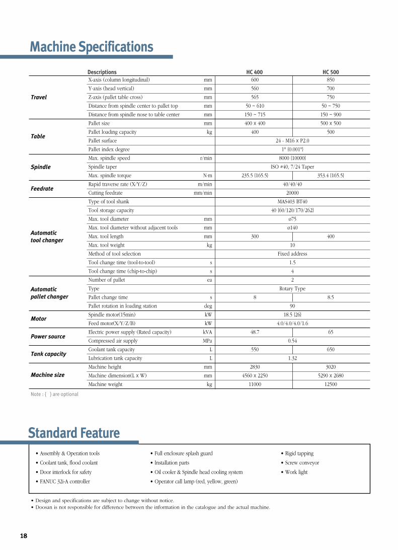
• Assembly & Operation tools
• Coolant tank, flood coolant
• Door interlock for safety
• FANUC 32i-A controller
• Full enclosure splash guard
• Installation parts
• Oil cooler & Spindle head cooling system
• Operator call lamp (red, yellow, green)
• Rigid tapping
• Screw conveyor
• Work light
• Design and specifications are subject to change without notice.• Doosan is not responsible for difference between the information in the catalogue and the actual machine.
Machine Specifications
Note : { } are optional
Descriptions HC 400 HC 500
X-axis (column longitudinal) mm 600 850
Y-axis (head vertical) mm 560 700
Z-axis (pallet table cross) mm 565 750
Distance from spindle center to pallet top mm 50 ~ 610 50 ~ 750
Distance from spindle nose to table center mm 150 ~ 715 150 ~ 900
Pallet size mm 400 x 400 500 x 500
Pallet loading capacity kg 400 500
Pallet surface 24 - M16 x P2.0
Pallet index degree 1° {0.001°}
Max. spindle speed r/min 8000 {10000}
Spindle taper ISO #40, 7/24 Taper
Max. spindle torque N.m 235.5 {165.5} 353.4 {165.5}
Rapid traverse rate (X/Y/Z) m/min 40/40/40
Cutting feedrate mm/min 20000
Type of tool shank MAS403 BT40
Tool storage capacity 40 {60/120/170/262}
Max. tool diameter mm ø75
Max. tool diameter without adjacent tools mm ø140
Max. tool length mm 300 400
Max. tool weight kg 10
Method of tool selection Fixed address
Tool change time (tool-to-tool) s 1.5
Tool change time (chip-to-chip) s 4
Number of pallet ea 2
Type Rotary Type
Pallet change time s 8 8.5
Pallet rotation in loading station deg 90
Spindle motor(15min) kW 18.5 {26}
Feed motor(X/Y/Z/B) kW 4.0/4.0/4.0/1.6
Electric power supply (Rated capacity) kVA 48.7 65
Compressed air supply MPa 0.54
Coolant tank capacity L 550 650
Lubrication tank capacity L 1.32
Machine height mm 2830 3020
Machine dimension(L x W) mm 4560 x 2250 5290 x 2680
Machine weight kg 11000 12500
Travel
Table
Spindle
Feedrate
Automatic
tool changer
Automatic
pallet changer
Motor
Machine size
Tank capacity
Power source
Standard Feature

19
NC Unit Specifications (Fanuc 32i-A)
- No. of Registered programs 500 ea- Optional block skip 1- Optional stop M01- Program file name 32 characters- Sequence number N 8-digit- Program protect- Program stop / end M00 / M02,M30- Programmable data input Tool offset and work offset are entered by G10, G11- Sub program call Up to 10 nesting- Tape code ISO / EIA Automatic discrimination- Work coordinate system G54 - G59- Additional work coordinate system (48 Pairs) G54.1 P1 - 48 pairs- Coordinate system rotation G68, G69- Extended part program editing- Optional chamfering corner R- Macro executor
OTHERS FUNCTIONS (Operation, Setting & Display, etc)- Alarm display- Alarm history display- Actual cutting speed display- Clock function- Cycle start / Feed hold- Display of PMC alarm message Message display when PMC alarm occurred- Dry run- Ethernet function (Embeded)- Graphic display Tool path drawing- Help function- Loadmeter display- DISPLAY/MDI unit 10.4" color TFT LCD / Keyboard for data input, soft-keys- Memory card interface- Operation functions Tape / Memory / MDI / Manual- Operation history display- DNC operation with memory card- Program restart- Run hour and part number display- Search function Sequence NO. / Program NO.- Self - diagnostic function- Servo setting screen- Single block- External data input- Multi language display
OPTIONAL SPECIFICATIONS- 3-dimensional coordinate conversion- Addition of tool pairs for tool life management 1024 pairs- Additional controlled axes Max. 6 axes per path- Automatic corner override G62- Chopping function G81.1- Cylindrical interpolation G07.1- Data server- Dynamic graphic display Machining profile drawing=> When the EZ Guide i is used, the Dynamic graphic display cannot application
- Interpolation type pitch error compensation- EZ Guide i (Doosan infracore Conversational Programming Solution)- Tape format for FS15- Increment system 1/10- Figure copying G72.1, G72.2- Manual handle feed 2/3 unit- Handle interruption- High speed skip function- Machining time stamp function- No. of Registered programs 1000 ea- Number of tool offsets 400 ea- Optional block skip addition 2~9 blocks- Part program storage 512KB (1280m)(Max.2Mbyte) 1MB (2560m)
- Playback function- Polar coordinate command G15 / G16- Polar coordinate interpolation G12.1 / G13.1- Programmable mirror image G50.1 / G51.1- Remote buffer- Scaling G50, G51- Single direction positioning G60- 3rd / 4th reference return - Stored stroke check 2 / 3- Tool load monitoring function (Doosan)- Doosan tool management package I- Tool offset G45 - G48- Position switch- Optional angle chamfering / corner R
AXES CONTROL- Controlled axes 4 (X, Y, Z, B)- Simultaneously controllable axes 4 axes
Positioning(G00)/Linear interpolation(G01) : 3 axesCircular interpolation(G02, G03) : 2 axes
- Backlash compensation- Emergency stop / overtravel- Follow up- Least command increment 0.001mm / 0.0001"- Least input increment 0.001mm / 0.0001"- Machine lock All axes / Z axis- Mirror image Reverse axis movement (Setting screen and M - function)- Stored pitch error compensation Pitch error offset compensation for each axis- Stored stroke check 1 Overtravel controlled by software
INTERPOLATION & FEED FUNCTION- Positioning G00- Linear interpolation G01- Circular interpolation G02, G03- Dwell G04- Exact stop check G09, G61 (mode)- Skip function G31- Reference point return check G27- Reference point return G28- 2nd reference point return G30- Feed per minute mm / min- Rapid traverse override F0 (fine feed), 25 / 50 / 100 %- Feedrate override (10% increments) 0 - 200 %- Jog override (10% increments) 0 - 200 %- Override cancel M48 / M49- Manual handle feed (1 unit)- Manual handle feedrate 0.1 / 0.01 / 0.001 mm- Automatic acceleration/deceleration- Helical interpolation- AI CONTOUR II 80 block preview- Machine condition selection function- Thread cutting, synchronous cutting- Program restart- Automatic corner deceleration (Specify AI Contour control II)- Feedrate clamp by circular acceleration- Linear ACC/DEC before interpolation (Specify AI Contour control II)- Linear ACC/DEC after interpolation- Control axis detach- Rapid traverse bell-shaped acceleration/deceleration- Smooth backlash compensation
SPINDLE & M-CODE FUNCTION- M- code function M 3 digits- Spindle orientation- Spindle serial output- Spindle speed command S5 digits- Spindle speed override (10% increments) 10 - 150 %- Spindle output switching - Retraction for rigid tapping- Rigid tapping G84, G74
TOOL FUNCTION- Tool nose radius compensation G40, G41, G42- Number of tool offsets 200 ea- Tool length compensation G43, G44, G49- Tool number command T3 digits- Tool life management- Tool offset memory C H/D code, Geometry / Wear memory- Tool length measurement
PROGRAMMING & EDITING FUNCTION- Absolute / Incremental programming G90 / G91- Auto. Coordinate system setting- Background editing- Canned cycle G73, G74, G76, G80 - G89, G99- Circular interpolation by radius programming- Plane selection G17, G18, G19- Custom macro B- Custom software size 512kb- Extended P-code Variables size 512kb- Addition of custom macro common variables #100 - #199, #500 - #999- Decimal point input- Reader/puncher interface RS - 232C- Inch / metric conversion G20 / G21- Label skip- Local / Machine coordinate system G52 / G53- Maximum commandable value ±99999.999mm (±9999.9999 inch)- Part program storage size (640m) 256kb
*) Prior consultation is required.

EXP1201SPi-serDesign and specifications are subject to change without prior notice.
Sales & Support Network
ARGENTINA/Rosario AUSTRALIA/Melbourne/Sydney AUSTRIA/Vienna BELGIUM/Gullegem BRAZIL/Sao paulo BULGARIA/Sofia CANADA/Edmonton/Montreal/Toronto/Vancouver
CHILE/Santiago CHINA/Beijing/Chongqing/Guangzhou/Shanghai/Shenyang COLOMBIA/Bogota CZECH/Brno DENMARK/Randers EGYPT/Cairo FINLAND/Tampere FRANCE/Annecy
GERMANY/Dusseldorf GREECE/Athens HONG KONG/Kowloon HUNGARY/Budapest INDIA/Bangalore/Pune INDONESIA/Jakarta IRAN/Tehran ISRAEL/Herzlia ITALY/Parma
MALAYSIA/Kuala Lumpur/Penang/Johor Bahru MEXICO/Guadalajara /Mexico City /Monterrey /Vera Cruz NETHERLANDS/Goorn NEW ZEALAND/Auckland NORWAY/Oslo PAKISTAN
/Islamabad/Karachi/Lahore PHILIPPINES/Manila POLAND/Krakow PORTUGAL/Lisbon ROMANIA/Bucharest RUSSIA/Moscow SAUDI ARABIA/Riyadh SINGAPORE/Singapore
SLOVENIA/Ljubljana SOUTH AFRICA/Kempton Park SPAIN/Barcelona SWEDEN/Stockholm SWITZERLAND/Zurich TURKEY/Istanbul THAILAND/Bangkok U.A.E/Sharjah
U. K./Leamington U.S.A./Atlanta/Birmingham/Charlotte/Chicago/Cincinnati/Cleveland/Dallas/Denver/Detroit/Houston/Indianapolis/Kansas City/Little Rock/Los Angeles/Milwaukee/Minneapolis
/New Orleans/Norfolk/Philadelphia/Phoenix/Pittsburgh/Portland/Rochester/Salt Lake City/San Diego/San Francisco/Seattle/Springfield/St. Louis/Tampa/Trenton/Tulsa VENEZUELA/Valencia
VIETNAM/Hanoi/Ho Chi Minh City
Head Office : Doosan Tower 20th FL., 18-12, Euljiro-6Ga, Jung-Gu, Seoul, Korea 100-730 Tel : ++82-2-3398-8693 / 8671 / 8680 Fax : ++82-2-3398-8699
Doosan Infracore America Corp.: 19A Chapin Rd. Pine Brook, NJ 07058, U.S.A.Tel : ++1-973-618-2500 Fax : ++1-973-618-2501
Doosan Infracore Germany GmbH : Hans-Böckler-Strasse 29, D-40764 Langenfeld-Fuhrkamp, Germany. Tel : ++49-2173-8509-0 Fax : ++49-2173-8509-60
Doosan Infracore Yantai Co., LTD : 13 Building, 140 Tianlin Road, Xuhui District, Shanghai, China (200233) Tel : ++86-21-6440-3384 (808, 805) Fax : ++86-21-6440-3389
http://www.doosaninfracore.com/machinetools