Embed Size (px)
Citation preview

Applied Thermal Sciences, Inc. Engineering Research & Development
High Performance
Gas-Metal Arc Welding
Final Report
Prepared for:
National Shipbuilding Research Program Sub-Contract # 2011-425
Prepared By:
Paul A. Blomquist Applied Thermal Sciences, Inc. And
Ken Johnson, Vigor Shipyards, Inc.
Submitted by:
Applied Thermal Sciences, Inc. 1861 Main Street
Sanford, ME 04073
February 29, 2012
Distribution Statement: Approved for Public Release; Distribution is Unlimited Data Rights Statement: Category B

2
Paul A. Blomquist is Principal Technologist, laser applications, at Applied Thermal Sciences, Sanford, ME; Ken Johnson is Senior Welding Engineer at Vigor Shipyards, Seattle, WA.
High-Performance Gas Metal Arc Welding
by
Paul A. Blomquist and Ken Johnson Abstract Work was performed aimed at investigating ways to increase the productivity and throughput of mechanized welding. The project was funded by the National Shipbuilding Research Program (NSRP), as a “Panel Project” supported by the NSRP Welding Technology Panel. Initial approach included considering ways to provide low-cost modifications to existing equipment/parameters, review of literature to ascertain usefulness of domestic and international changes, and discussions with equipment makers. Ultimately, it became apparent that modern inverter-type welding power sources might be capable of operation in ranges that would significantly enhance productivity. Following this approach, several power supplies were tested, and found to be capable of operating at much higher speeds than used for typical GMAW. The project team examined easily implemented parameter sets for inverter-type power supplies that demonstrate excellent penetration at double the speed of typical Gas Metal Arc Welding (GMAW). Welding speed was increased as much as 2X and more, with good weld penetration. The equipment and parameters are capable of operating on panel lines, in other mechanized or robotic welding areas, and in pipe shops. All welding was done on 0.5-inch DH-36 plate that had been cleaned of oxides by means of grit blasting, wire brushing, sanding, or grinding. Introduction At this time, there are several methods either available or under development that promise a range of increased speed and penetration for GMAW operations. The most productive of these, Hybrid Laser Arc Welding (HLAW) provides a 10X increase in weld speed, but comes with a vastly higher equipment cost, often greater than 100X, and requires very specialized equipment. When HLAW is justified, it’s a clear winner, but there needs to be something out there for the rest of us. Is there an opportunity to achieve higher weld speeds and lower heat inputs, thus reducing cost and distortion? Project Team The project team consisted of Applied Thermal Sciences, Sanford, Maine, as lead, Vigor Shipyards, Seattle, WA, Huntington-Ingalls Industries, Ingalls Shipbuilding (HII-IS), Pascagoula, MS, and Huntington-Ingalls Industries, Newport News Shipbuilding (HII-NNS), Newport News, VA. Several major welding equipment manufacturers provided on-site testing and/or information and guidance for the project, including Miller Electric, ESAB, and Lincoln Electric.

3
Review of Technologies In this project mainstream technologies and/or combination of technologies were reviewed. Many of these are already installed at fabricators, and can achieve the goal of doubling weld speed while giving excellent penetration. Recent tests at Vigor Shipyards, Applied Thermal Sciences (ATS), Miller, Fronius, and Thermadyne, have shown this is possible. This work along with information from other major equipment manufacturers has established the fact that an installed base of equipment can be operated at parameters that will increase productivity. Four technologies were initially reviewed: HLAW [1], Hybrid Plasma-GMAW [2], and GMAW modified with a unique double-electrode configuration [3], and a twin-electrode system from Fronius [4]. All of these had potential for increasing welding speed and/or penetration. However, during this review, some international literature was found that disclosed potential for the kind of improvements sought but using simpler single-unit, single electrode GMAW procedures and inverter-type power sources [5]. Reference [5], the work of Dr. Zdeněk Hudec of the Czech Republic, proposed two important points: primarily, that the current state of technology contained in GMAW inverter-type power supplies are capable of operating in parameter ranges and welding speeds that can provide significant improvements in weld speed and reduction of heat inputs; and also that an operational range at lower-than-typical GMAW voltages were useful for these improvements. Inquiry into GMAW with Inverter-Type Power Supplies Since the project necessarily must focus on the needs of shipbuilders, and the most-frequent weld used in shipbuilding is the single-pass fillet weld, the opportunity to explore and attempt to duplicate this work was compelling. Thus, the focus of the effort became the validation of these two points. Fundamentally, if inverters that are already installed can be utilized in new ways, especially to increase weld speed and lower heat inputs, thus reducing cost and distortion, at the same time providing the necessary weld quality, the value of this inquiry is compelling. Dr. Hudec explains that modern inverter technology provide “excellent dynamic properties” for welding. Thus, operation in regions in which older types of GMAW power supplies would be unstable might be possible and useful with modern inverters. Hudec proposes a “short-spray” parameter region that uses lower voltages than used in the past for spray-arc GMAW. As shown in Figure 1, and explained in reference [5] and elsewhere in the literature, the short-spray region is stated
as several Volts below standard spray, but well above the short-circuiting transfer region. Given this information, the project team set out to explore this operational parameter area using
Figure 1. “Short-Spray” Process Concept (from Ref. [5])

4
several inverter power supplies in various locations. The goal was simply to achieve higher weld speeds and small fillet sizes. In many instances in shipbuilding, a fillet weld with a leg length of 0.125” is allowable by design, but traditional process implementations have not achieved this goal. With the above information as a starting point, the test program proceeded to make necessary adjustments to achieve the desired welding speeds and fillet size. Test Program To provide a reasonably constant environment for the testing, all welding (with one exception) was done using the same electrode (E70S-6, 0.045-in. dia.) and shielding gas (Ar-5%CO2). Similarly, the base metal selected was DH-36, a common shipbuilding steel of 51 ksi yield strength. For testing done in the US, web and flange plates were cut from a single heat of DH-36 and sent to the various test sites. Material thickness of 0.500 inch was selected. This thickness was chosen to provide a higher heat sink, and thus inhibit wetting, further testing the stability and performance of the various power supplies at the higher speeds envisioned for testing. The first set of tests was conducted at Vigor Shipyards in Seattle, WA. For these tests, two simplified tractor arrangements were tried, with a friction-type tractor (ESAB “Miggy-Trac™”) used for most of the work. This set-up is shown in Figure 2. Welding equipment consisted of an ESAB Aristo-650 power supply, associated feeder, and a U-8 controller. Special “synergic lines” were not used, with the system operating in a straight CV mode, allowing independent control of voltage and wire feed. Welding electrode used was ESAB “Aristo-Rod™”. This electrode is not copper-coated. Subsequent trials in other locations made use of both copper- and non-copper-coated electrodes.
Figure 2. Set-up for welding trials at Vigor Shipyards. General arrangement of tractor, torch,
and test pieces. Tractor is guided by friction of drive wheels providing force to guide rollers.

5
Initial trials were made at typical welding speeds and spray arc parameters. These welds were made at a weld speed of ~20-ipm, and while larger than intended, were acceptable in every respect. This weld, shown in Figure 3, established that the complete welding system was capable of making quality welds.
Several iterations were then made using various parameter sets. Travel speeds from 40 to 60 ipm were used, with the optimum weld speed found to be 55 ipm. For this weld, voltage was set at 26.2V, and with a wire feed speed of 500 ipm, current was recorded at 363A. Shown in Figure 3, this weld exhibited a symmetrical fillet leg length of 0.125-inch. A macro-section (Figure 4B) shows that at this travel speed, penetration and overall weld soundness are excellent.
In addition to the set-up and test welds, a total of eleven additional coupons were welded at Vigor Shipyard. A few butt welds were made at the same parameter sets as the fillets, and
Figure 4. A: Fillet weld made at 55 ipm; B: Macro-etch showing excellent penetration (slight bleed-out of etchant at root).
Figure 3. Set-up fillet weld made at 15 ipm, 28.5 V, 375A (WFS 385 ipm); Leg length =5/16”

6
several of these were sectioned and etched for information. A number of these are shown below in Figure 5.
In all cases for welds on the DH-36 test material, a wire feed speed of 500 ipm was used. Voltages varied only slightly, from 25.5 to 26.5V. Electrical stickout was held constant at 0.25 inches. Penetration and weld soundness were excellent in all cases. Butt welds made at the same parameters on square butt joints naturally showed high reinforcement, but again, penetration and soundness were excellent.
Figure 5. Top: fillet and butt welds made on DH-36 test material. Bottom left, fillet weld made at 59 ipm. Bottom right: macro of butt weld made at 59 ipm.

7
The second set of tests was performed at Applied Thermal Sciences (ATS) in Sanford, Maine. An ESAB Aristo 500™ power supply and associated feeder was used, with parameters entered via the ESAB U-8™ controller. Motion was accomplished using an articulated robot equipped a laser-vision seam tracker. Set-up is shown in Figure 6, below.
The intent of these tests was to duplicate the weld speed (55ipm), size (0.125-in.), and quality achieved in the tests at Vigor Shipyards. To determine if electrode coating was significant, a copper-clad E70S-6 electrode was used for these welds. Again, shielding gas was Ar-5%CO2. This proved to be the case, as shown in Figure 7.
Figure 6. A: Set-up for welding at ATS.
Figure 7. Left: Fillet weld made at 55 ipm; Right: 1/8” symmetrical leg size.

8
Further testing was performed at three other sites. A Lincoln Electric PowerWave 455M/STT ™ unit was tested at Concurrent Technologies Corporation, Johnstown, PA. A Miller Electric Axcess 450-DI system was used for testing at Miller’s facility in Swedesboro, NJ. Thermadyne made a 4000W available for testing in Lebanon, NH. Both copper-coated and non-coated 70S-6 electrodes were tested at Thermadyne. Motion systems employed ranged from simple tractors to robots. Acceptable welds were made at speeds from 40-55 inches per minute. Voltages varied from a low of 25V to values above 28V, more typical of traditional spray-arc procedures. Wire feed speeds used varied from 500 ipm to slightly over 600 ipm. For brevity, details are not presented in the main body of this report. Relevant pictures and data are included in the appendix that follows. Additionally, there are macros of work done in Austria by Fronius, with a tandem system. While not a duplication, this is reported in the interest of completeness. Certainly, the actual parameter values will vary, but the fundamental concept: that modern inverters have capabilities that may be underutilized in the industry, has been established. It is anticipated that power sources from other makers may easily meet or exceed these results. Summary Time and resources of the project did not allow for more tests in other locations, nor was it possible to perform the kind of exhaustive development to optimize parameters for every combination of power supply, wire feeder and electrode, to say nothing of potential variations in shielding gas mixtures. The point of the effort was to show that higher weld speeds and lower heat inputs are enabled with many of the current generation of inverter-type power supplies, and that a capital-intensive approach may not be necessary in all cases to improve productivity and quality. Conclusions Fundamentally, the concept that the dynamic response of modern high-frequency inverter power supplies for GMAW offers potential for a wider range of operation, and for reductions in weld time and distortion, was established in these trials. Also, this work indicates that other power supplies from other makers are very likely able to achieve similar results. It must be remembered that these tests are very preliminary in nature, and that all of the effects of parameter changes must be assessed before implementing them in actual production. Most codes and standards have limits on the degree of changes that may be made to qualified procedures, and the level of effort required for requalification may vary. Further, for materials that are sensitive to cooling rates, the effect of changes to heat input must be evaluated. Given all of the above, the potential for significant improvement in welding operations may already exist on the shop floor of many fabricators. That’s good news. Recommendations There is fertile ground for further work in the parametric regimes studied herein. Certainly, work with surfaces coated with pre-construction primers is an area that should be investigated. Additionally, work should be performed on higher-yield steels, and welding of aluminum should be considered as well.

9
Acknowledgements This project would not have been possible without the cooperation and assistance of many others. The author wishes to thank Darrel Rondeau, Welding & Materials Engineer at ATS; Brian Fowler, Welding Engineer at Concurrent Technologies Corporation; Paul Hebert, Chief Welding Engineer and Huntington-Ingalls Industries (HII) Newport News Shipbuilding; Lee Kvidahl, Chief Welding Engineer and Huntington-Ingalls Industries (HII) Ingalls Shipbuilding; and Wladyslaw Jaxa-Rosen, senior expert engineer with Bombardier Transportation: for advice, information, and support throughout the project. In addition, representatives from equipment manufacturers arranged and provided time, information, and testing, including Mike Ludwig (Fronius); Harry Sadler (Lincoln); Mike Novak (Miller);Tom Ferri (Thermadyne); and Bob Bitzkey (ESAB). Many others have been part of the effort and the author apologizes to any that may have been missed and to all those who cannot be mentioned in the need for brevity in this article. References
1. Defalco, J. 2007. Practical applications for hybrid laser welding. Welding Journal 86(10): 47.
2. Finnigan, B. 2010. A New Hybrid Plasma-GMA Welding Process Features Many Advantages Over GMAW. http://www.aws.org/w/a/conferences/newweldingtech/presentations.html
3. Li, K. H., and Zhang, Y. M. 2008. Consumable Double-Electrode GMAW — Part 1: The
Process. http://www.aws.org/wj/supplement/wj0108-11.pdf
4. Ludwig, M. Fronius International Gmbh. 2012. Email.
5. Hudec, Z. 2010. Optimization of Source-Wire-Gas Systems for Efficient Robotic Welding. Third International Conference on Multidisciplinary Design Optimization and Applications, 21-23 June 2010, Paris, France. www.asmdo.com/conference2010/
10
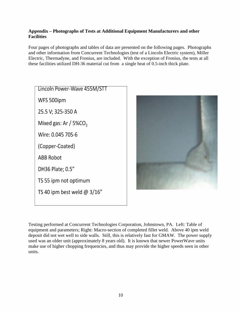
Appendix – Photographs of Tests at Additional Equipment Manufacturers and other Facilities Four pages of photographs and tables of data are presented on the following pages. Photographs and other information from Concurrent Technologies (test of a Lincoln Electric system), Miller Electric, Thermadyne, and Fronius, are included. With the exception of Fronius, the tests at all these facilities utilized DH-36 material cut from a single heat of 0.5-inch thick plate.
Testing performed at Concurrent Technologies Corporation, Johnstown, PA. Left: Table of equipment and parameters; Right: Macro-section of completed fillet weld. Above 40 ipm weld deposit did not wet well to side walls. Still, this is relatively fast for GMAW. The power supply used was an older unit (approximately 8 years old). It is known that newer PowerWave units make use of higher chopping frequencies, and thus may provide the higher speeds seen in other units.

11
Testing at Miller Electric Automation Facility, Swedesboro, NJ

12
Tests performed at Thermadyne, Lebanon, NH:
As part of these tests, a high-speed recording oscilloscope was connected from the wire feeder “hot” terminal to ground. Voltage traces showed stable transitions, with very little difference between the copper-coated and non-coated wires.

13
Testing performed at Fronius, Austria, of a tandem system. As noted below, very high travel speeds were achieved. Macros show excellent penetration.
Note evidence of superior wetting and excellent penetration. Again, these are tandem systems, with higher cost and complexity. As such, they are not part of the inquiry into improvements with simpler single-wire systems, but are presented as an item of interest to the community. Type of wire was not reported. Materials were not reported, but were not the 0.5-inch thick DH-36 that was used in all the other tests at the other sites.