Embed Size (px)
Citation preview

Cat.No.C42E-5
MurataManufacturing Co., Ltd.
High Frequency PowerCeramic Capacitors
!Note Please read rating and !CAUTION (for storage, operating, rating, soldering, mounting and handling) in this PDF catalog to prevent smoking and/or burning, etc.This catalog has only typical specifications. Therefore, you are requested to approve our product specifications or to transact the approval sheet for product specificaions before ordering.
C42E5.pdf 05.5.31

CONTENTS
Flange Type/Disc Type DCT/DCA Series
" Specifications and Test Methods
" Typical Characteristics Data
Small Type DC5 Series
" Specifications and Test Methods
1
2
4
7
8
9
11
12
1
2
! Caution/Notice
High Frequency Power Ceramic Capacitors
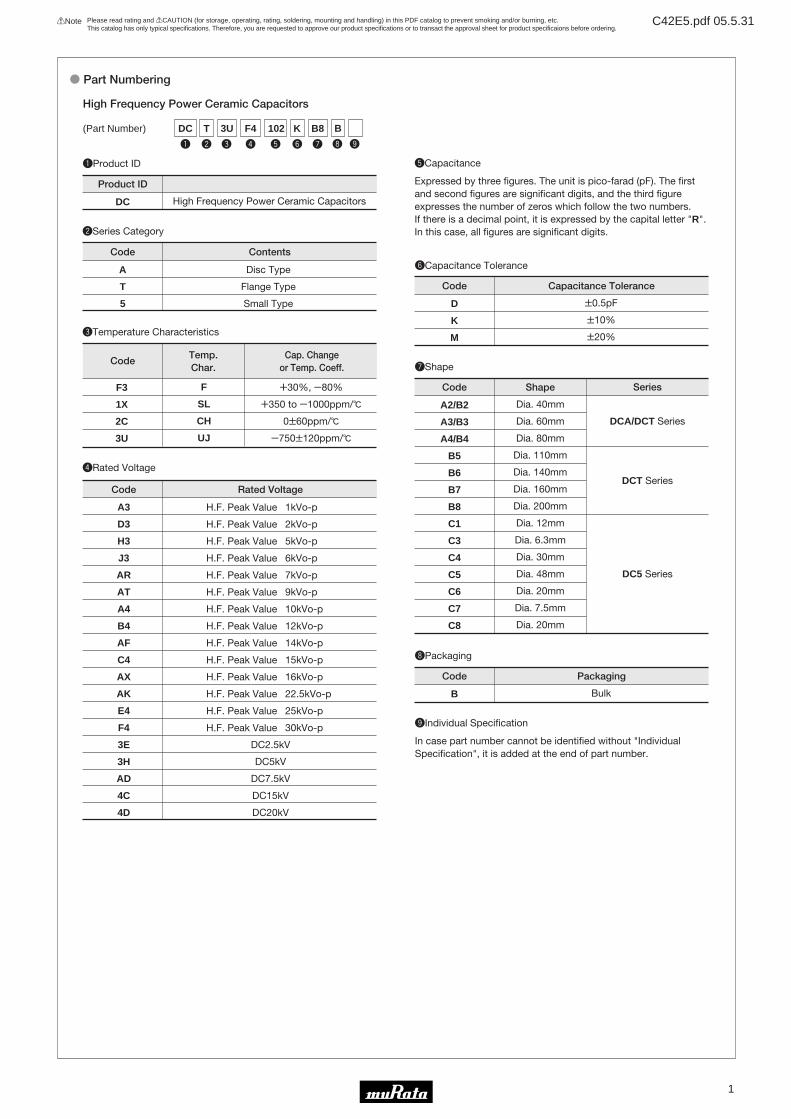
Part Numbering
Recycled Paper
!Note Please read rating and !CAUTION (for storage, operating, rating, soldering, mounting and handling) in this PDF catalog to prevent smoking and/or burning, etc.This catalog has only typical specifications. Therefore, you are requested to approve our product specifications or to transact the approval sheet for product specificaions before ordering.
C42E5.pdf 05.5.31
1
(Part Number)
High Frequency Power Ceramic Capacitors
qProduct ID
CodeTemp.Char.
F
SL
CH
UJ
F3
1X
2C
3U
W30%, Y80%
W350 to Y1000ppm/D
0T60ppm/D
Y750T120ppm/D
Cap. Changeor Temp. Coeff.
eTemperature Characteristics
wSeries Category
rRated Voltage
Rated VoltageCode
A3
D3
H3
J3
AR
AT
A4
B4
AF
C4
AX
AK
E4
F4
3E
3H
AD
4C
4D
1kVo-p
2kVo-p
5kVo-p
6kVo-p
7kVo-p
9kVo-p
10kVo-p
12kVo-p
14kVo-p
15kVo-p
16kVo-p
22.5kVo-p
25kVo-p
30kVo-p
DC2.5kV
DC5kV
DC7.5kV
DC15kV
DC20kV
H.F. Peak Value
H.F. Peak Value
H.F. Peak Value
H.F. Peak Value
H.F. Peak Value
H.F. Peak Value
H.F. Peak Value
H.F. Peak Value
H.F. Peak Value
H.F. Peak Value
H.F. Peak Value
H.F. Peak Value
H.F. Peak Value
H.F. Peak Value
yCapacitance Tolerance
uShape
iPackaging
ContentsCode
A
T
5
Disc Type
Flange Type
Small Type
tCapacitance
Expressed by three figures. The unit is pico-farad (pF). The first and second figures are significant digits, and the third figure expresses the number of zeros which follow the two numbers.If there is a decimal point, it is expressed by the capital letter "R". In this case, all figures are significant digits.
Capacitance ToleranceCode
D
K
M
T0.5pF
T10%
T20%
ShapeCode
A2/B2
A3/B3
A4/B4
B5
B6
B7
B8
C1
C3
C4
C5
C6
C7
C8
Dia. 40mm
Dia. 60mm
Dia. 80mm
Dia. 110mm
Dia. 140mm
Dia. 160mm
Dia. 200mm
Dia. 12mm
Dia. 6.3mm
Dia. 30mm
Dia. 48mm
Dia. 20mm
Dia. 7.5mm
Dia. 20mm
Series
DCA/DCT Series
DCT Series
DC5 Series
Product ID
DC High Frequency Power Ceramic Capacitors
PackagingCode
B Bulk
oIndividual Specification
In case part number cannot be identified without "Individual Specification", it is added at the end of part number.
t
102
y
K
q
DC
u
B8
r
F4
e
3U
w
T
i
B
o
o Part Numbering
!Note Please read rating and !CAUTION (for storage, operating, rating, soldering, mounting and handling) in this PDF catalog to prevent smoking and/or burning, etc.This catalog has only typical specifications. Therefore, you are requested to approve our product specifications or to transact the approval sheet for product specificaions before ordering.
C42E5.pdf 05.5.31
2
High Frequency Power Ceramic Capacitors
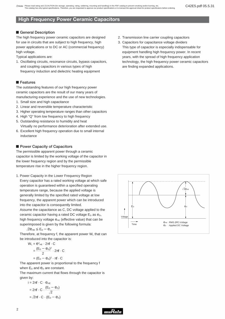
! General DescriptionThe high frequency power ceramic capacitors are designedfor use in circuits that are subject to high frequency, highpower applications or to DC or AC (commercial frequency)high voltage.Typical applications are:1. Oscillating circuits, resonance circuits, bypass capacitors,
and coupling capacitors in various types of highfrequency induction and dielectric heating equipment
2. Transmission line carrier coupling capacitors3. Capacitors for capacitance voltage dividers
This type of capacitor is especially indispensable forequipment handling high frequency power. In recentyears, with the spread of high frequency applicationtechnology, the high frequency power ceramic capacitorsare finding expanded applications.
2eHE
eDED
eHE
eD
: RMS (RF) Voltage : Applied DC VoltageTime
Voltage
! FeaturesThe outstanding features of our high frequency powerceramic capacitors are the result of our many years ofmanufacturing experience and the use of new technologies.1. Small size and high capacitance2. Linear and reversible temperature characteristic3. Higher operating temperature ranges than other capacitors4. High "Q" from low frequency to high frequency5. Outstanding resistance to humidity and heat
Virtually no performance deterioration after extended use.6. Excellent high frequency operation due to small internal
inductance
! Power Capacity of CapacitorsThe permissible apparent power through a ceramiccapacitor is limited by the working voltage of the capacitor inthe lower frequency region and by the permissibletemperature rise in the higher frequency region.
1. Power Capacity in the Lower Frequency RegionEvery capacitor has a rated working voltage at which safeoperation is guaranteed within a specified operatingtemperature range, because the applied voltage isgenerally limited by the specified rated voltage at lowfrequency, the apparent power which can be introducedinto the capacitor is consequently limited.Assume the capacitance as C, DC voltage applied to theceramic capacitor having a rated DC voltage ED as eD,high frequency voltage eHE (effective value) that can besuperimposed is given by the following formula:
2eHE V ED Y eD
Therefore, at frequency f, the apparent power WL that canbe introduced into the capacitor is:
WL = e2HE · 2πf · C
=(ED Y eD)2
· 2πf · C2
= (ED Y eD)2 · πf · CThe apparent power is proportional to the frequency fwhen ED and eD are constant.The maximum current that flows through the capacitor isgiven by:
i = 2πf · C · eHE
= 2πf · C · (ED Y eD)
2= 2πf · C · (ED Y eD)

!Note Please read rating and !CAUTION (for storage, operating, rating, soldering, mounting and handling) in this PDF catalog to prevent smoking and/or burning, etc.This catalog has only typical specifications. Therefore, you are requested to approve our product specifications or to transact the approval sheet for product specificaions before ordering.
C42E5.pdf 05.5.31
3
High Frequency Power Ceramic Capacitors
2. Power Capacity in the Higher Frequency RegionThe allowable power of the ceramic capacitor in thehigher frequency region is generally limited by heatingdue to dielectric losses and temperature rise caused byheating, due to Joule heat at areas where the terminalsare connected to the electrodes.Thus, the permissible power at high frequencies is limitedby the allowable internal temperature rise. Thepermissible power is increased as the internaltemperature rises.For example, when a high frequency voltage of frequencyf is applied to a capacitor of capacitance C, the heatgenerated from dielectric loss is expressed by:
Wr1 = DF · WL
= DF · 2πf · C · e2HE
= DF · i2 . . . . . . . . . . . . . . . . (1)
C · 2πfWL : Apparent power passing through the capacitoreHE : Applied high frequency voltage (Effective value)i : High frequency currentR : High frequency resistance at the electrodes and
connecting terminalsThe heating due to Joule heat at areas where electrodesand terminals join is given by:
Wr2 = R · i2
= R · i · 2πf · C · eHE
= R · 2πf · C · WL . . . . . . . . . . . . . . . (2)Thus, the total calorific value is expressed by:
Wr = Wr1 + Wr2
= DF · WL + R · 2πf · C · WL
The total calorific value Wr is made up of a term in whichthe value is independent of frequency when WL isconstant, and a second term in which the value isproportional to frequency.
(This is based on the assumption that DF and R remainconstant independent of f.)Thus, the value in the second term is small when thefrequency is relatively low; the first term becomesdominant.As a result, the calorific value becomes proportional tothe apparent power WL which passes through thecapacitor independent of frequency.At high frequencies, on the other hand, the second termbecomes dominant, and Wr becomes proportional to WL
and frequency.When Wr is maintained at a constant value, therefore, thepower capacity WL that can be passed through thecapacitor remains constant independent of frequency atrelatively low frequencies, while at high frequencies, WL
decreases, being inversely proportional to frequency.
Critical frequencies f1 and f2 vary with the shape,operating voltage, capacitance, etc. of a capacitor but f1ranges from 200kHz to 2MHz and f2, from 2MHz to20MHz.
! Main Uses3. The example of a circuit Induction-heating equipment
WL
f1 f2
I II III
PowerCapacity
Frequency
+B C1 C3
C2
C4 C5
C7
C6
C1C3 : DCTC5C7 : DCT
C2 : DCTC4C6 : DCT
Induction heatingequipment
High frequencyheating equipment
Medical equipment
Radio communicationequipment
High frequency powersupply
Hardening, MeltingFurnace, Tube welder
Welding for PVC, WoodDryer
Magnetic resonanceimaging (MRI)
Ships, Airplanes
RF plasma generator
Industrial laser equipment(RF excitation)
DCT series
DCT series, DCAseries
DC5 series
DC5 series
DCT series, DCAseries, DC5 series
DCT series
Equipment Use Recommendation

!Note • Please read rating and !CAUTION (for storage, operating, rating, soldering, mounting and handling) in this catalog to prevent smoking and/or burning, etc. • This catalog has only typical specifications because there is no space for detailed specifications. Therefore, please approve our product specifications or transact the approval sheet for product specifications before ordering.
1
4
Flange Type/Disc Type DCT/DCA Series
High Frequency Power Ceramic Capacitors
! Features1. Small size and high capacitance2. Linear and reversible temperature characteristics3. Very high "Q" and high insulation resistance from low
frequency to high frequency4. No performance deterioration after extended
life–excellent humidity and thermal resistance5. Low series inductance with excellent frequency
performance6. High power capacity for small capacitor due to low level
of heating by dielectric loss when high voltage at highfrequency is applied
! Applications1. Oscillators, coupling circuit, or bypass capacitors in
industrial or medical high frequency appliances such ashigh frequency heating equipment or ultrasonicinstruments
2. Coupling capacitors for transmission line and carrierfrequency equipment
! Marking1. Type Code2. Capacitance and Tolerance3. Rated Voltage (H.F.)4. Rated Voltage (Vdc)5. Rated Power Capacity6. Prod. Lot No.7. Manufacturer's Identification
! Insulation CoatingCapacitor surface is coated with insulation resin exceptterminals. Temp. coefficient is shown by the following colormarking.
Char. SL, UJ: GreenChar. CH: Orange
ShapeCode
B2
B3
B4
ISO M4
ISO M6
ISO M6
Terminal Dimensions (mm)
C
10
12
18
d
8
8
8
h
DCT SeriesShape Code B2-B4
DCT SeriesShape Code B5-B8
DCA Series
c
øD
ød
HT
h
<Fig. 1>(in mm)
c
øDd
HT
h
<Fig. 2>(in mm)
c
øD
ød
HT
h
<Fig. 3>(in mm)
ShapeCode
A2
A3
A4
ISO M5
ISO M6
ISO M6
Terminal Dimensions (mm)
C
10
12
18
d
8
8
8
h
ShapeCode
B5
B6
B7
B8
ISO M8
ISO M8
ISO M8
ISO M10
Terminal Dimensions (mm)
C
17
21
21
35
d
15
15
15
20
h
!Note Please read rating and !CAUTION (for storage, operating, rating, soldering, mounting and handling) in this PDF catalog to prevent smoking and/or burning, etc.This catalog has only typical specifications. Therefore, you are requested to approve our product specifications or to transact the approval sheet for product specificaions before ordering.
C42E5.pdf 05.5.31
1
5
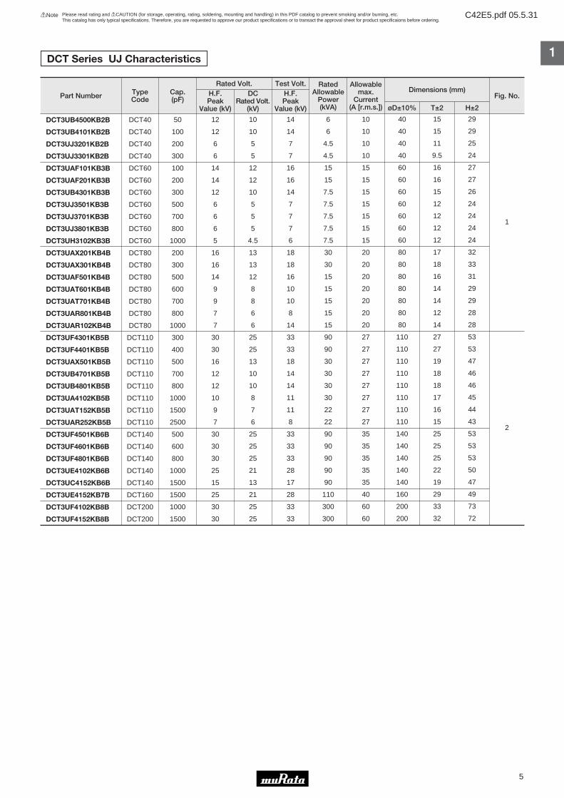
DCT Series UJ Characteristics
Part Number Cap.(pF)
TypeCode
Rated Volt. Test Volt. RatedAllowable
Power(kVA)
Allowablemax.
Current(A [r.m.s.])
Dimensions (mm)Fig. No.
øD±10% T±2 H±2
H.F.Peak
Value (kV)
DCRated Volt.
(kV)
H.F.Peak
Value (kV)
DCT3UB4500KB2B
DCT3UB4101KB2B
DCT3UJ3201KB2B
DCT3UJ3301KB2B
DCT3UAF101KB3B
DCT3UAF201KB3B
DCT3UB4301KB3B
DCT3UJ3501KB3B
DCT3UJ3701KB3B
DCT3UJ3801KB3B
DCT3UH3102KB3B
DCT3UAX201KB4B
DCT3UAX301KB4B
DCT3UAF501KB4B
DCT3UAT601KB4B
DCT3UAT701KB4B
DCT3UAR801KB4B
DCT3UAR102KB4B
DCT3UF4301KB5B
DCT3UF4401KB5B
DCT3UAX501KB5B
DCT3UB4701KB5B
DCT3UB4801KB5B
DCT3UA4102KB5B
DCT3UAT152KB5B
DCT3UAR252KB5B
DCT3UF4501KB6B
DCT3UF4601KB6B
DCT3UF4801KB6B
DCT3UE4102KB6B
DCT3UC4152KB6B
DCT3UE4152KB7B
DCT3UF4102KB8B
DCT3UF4152KB8B
DCT40
DCT40
DCT40
DCT40
DCT60
DCT60
DCT60
DCT60
DCT60
DCT60
DCT60
DCT80
DCT80
DCT80
DCT80
DCT80
DCT80
DCT80
DCT110
DCT110
DCT110
DCT110
DCT110
DCT110
DCT110
DCT110
DCT140
DCT140
DCT140
DCT140
DCT140
DCT160
DCT200
DCT200
50
100
200
300
100
200
300
500
700
800
1000
200
300
500
600
700
800
1000
300
400
500
700
800
1000
1500
2500
500
600
800
1000
1500
1500
1000
1500
12
12
6
6
14
14
12
6
6
6
5
16
16
14
9
9
7
7
30
30
16
12
12
10
9
7
30
30
30
25
15
25
30
30
10
10
5
5
12
12
10
5
5
5
4.5
13
13
12
8
8
6
6
25
25
13
10
10
8
7
6
25
25
25
21
13
21
25
25
14
14
7
7
16
16
14
7
7
7
6
18
18
16
10
10
8
14
33
33
18
14
14
11
11
8
33
33
33
28
17
28
33
33
6
6
4.5
4.5
15
15
7.5
7.5
7.5
7.5
7.5
30
30
15
15
15
15
15
90
90
30
30
30
30
22
22
90
90
90
90
90
110
300
300
10
10
10
10
15
15
15
15
15
15
15
20
20
20
20
20
20
20
27
27
27
27
27
27
27
27
35
35
35
35
35
40
60
60
40
40
40
40
60
60
60
60
60
60
60
80
80
80
80
80
80
80
110
110
110
110
110
110
110
110
140
140
140
140
140
160
200
200
15
15
11
9.5
16
16
15
12
12
12
12
17
18
16
14
14
12
14
27
27
19
18
18
17
16
15
25
25
25
22
19
29
33
32
29
29
25
24
27
27
26
24
24
24
24
32
33
31
29
29
28
28
53
53
47
46
46
45
44
43
53
53
53
50
47
49
73
72
1
2

!Note Please read rating and !CAUTION (for storage, operating, rating, soldering, mounting and handling) in this PDF catalog to prevent smoking and/or burning, etc.This catalog has only typical specifications. Therefore, you are requested to approve our product specifications or to transact the approval sheet for product specificaions before ordering.
C42E5.pdf 05.5.31
Part Number Cap.(pF)
TypeCode
Rated Volt. Test Volt. RatedAllowable
Power(kVA)
Allowablemax.
Current(A [r.m.s.])
Dimensions (mm)Fig. No.
øD±10% T±1 H±2
H.F.Peak
Value (kV)
DCRated Volt.
(kV)
H.F.Peak
Value (kV)
Part Number Cap.(pF)
TypeCode
Rated Volt. Test Volt. RatedAllowable
Power(KVA)
Allowablemax.
Current(A [r.m.s.])
Dimensions (mm)Fig. No.
øD±10% T±1 H±2
H.F.Peak
Value (kV)
DCRated Volt.
(kV)
H.F.Peak
Value (kV)
Part Number Cap.(pF)
TypeCode
Rated Volt. Test Volt. RatedAllowable
Power(kVA)
Allowablemax.
Current(A [r.m.s.])
Dimensions (mm)Fig. No.
øD±10% T±2 H±2
H.F.Peak
Value (kV)
DCRated Volt.
(kV)
H.F.Peak
Value (kV)
1
6
DCT2CAX101KB4B
DCT2CAX151KB4B
DCT2CAK101KB5B
DCT2CAK201KB5B
DCT80
DCT80
DCT110
DCT110
100
150
100
200
16
16
22.5
22.5
19
19
26
26
18
18
25
25
30
30
67.5
67.5
20
20
27
27
80
80
110
110
17
14
22
22
32
29
46
46
1
2
DCA1XA3102KA2B DAT40 1000 1
DCA3UD3101KA2B
DCA3UD3201KA2B
DCA3UD3301KA2B
DCA3UD3401KA2B
DCA3UD3501KA2B
DCA3UD3102KA3B
DCA3UD3152KA4B
DAT40
DAT40
DAT40
DAT40
DAT40
DAT60
DAT80
100
200
300
400
500
1000
1500
2
2
2
2
2
2
2
6
6
3.5
3.5
3.5
6
6
3
3
3
3
3
3
3
3
3
2.2
2.2
2.2
5
7
8.5
8.5
8.5
8.5
8.5
14
18
40
40
40
40
40
60
80
2.8
2.8
2.8
1.4
1.4
1.8
2.2
24
24
24
22
22
23
27
3
3.5 2 2 5 40 2.4 23 3
DCT Series CH Characteristics
DCA Series SL Characteristics
DCA Series UJ Characteristics
!Note Please read rating and !CAUTION (for storage, operating, rating, soldering, mounting and handling) in this PDF catalog to prevent smoking and/or burning, etc.This catalog has only typical specifications. Therefore, you are requested to approve our product specifications or to transact the approval sheet for product specificaions before ordering.
C42E5.pdf 05.5.31
1
7
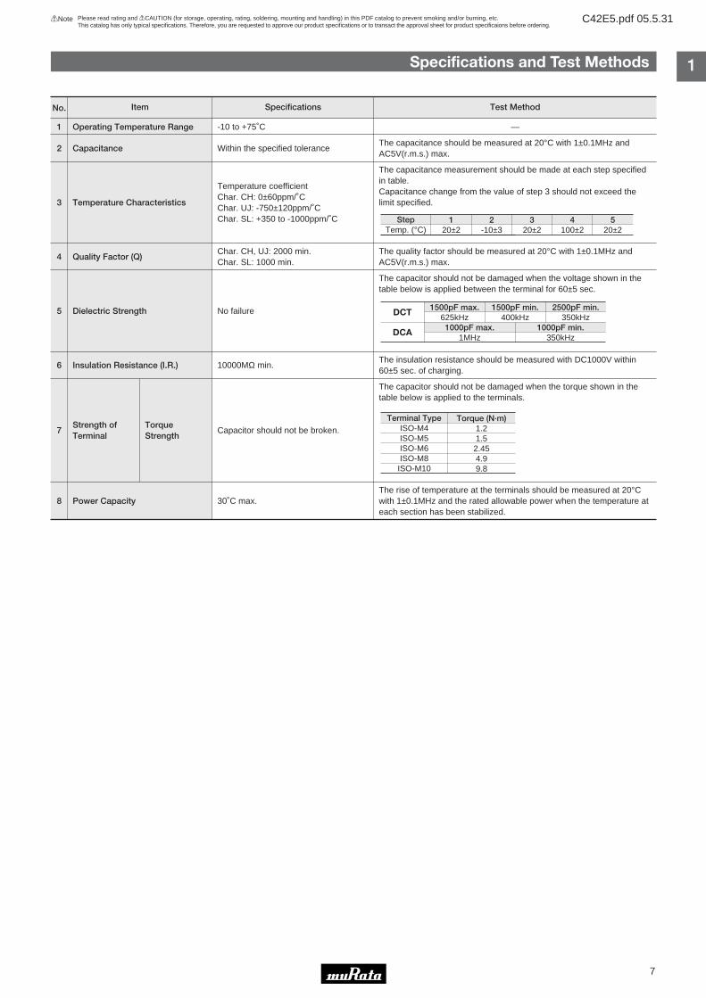
Specifications and Test Methods
1
2
3
4
5
6
7
8
Operating Temperature Range
Capacitance
Temperature Characteristics
Quality Factor (Q)
Dielectric Strength
Insulation Resistance (I.R.)
Strength of TorqueTerminal Strength
Power Capacity
Item Specifications Test MethodNo.
-10 to +75˚C
Within the specified tolerance
Temperature coefficientChar. CH: 0±60ppm/˚CChar. UJ: -750±120ppm/˚CChar. SL: +350 to -1000ppm/˚C
Char. CH, UJ: 2000 min.Char. SL: 1000 min.
No failure
10000MΩ min.
Capacitor should not be broken.
30˚C max.
—
The capacitance should be measured at 20°C with 1±0.1MHz andAC5V(r.m.s.) max.
The capacitance measurement should be made at each step specifiedin table.Capacitance change from the value of step 3 should not exceed thelimit specified.
The quality factor should be measured at 20°C with 1±0.1MHz andAC5V(r.m.s.) max.
The capacitor should not be damaged when the voltage shown in thetable below is applied between the terminal for 60±5 sec.
The insulation resistance should be measured with DC1000V within60±5 sec. of charging.
The capacitor should not be damaged when the torque shown in thetable below is applied to the terminals.
The rise of temperature at the terminals should be measured at 20°Cwith 1±0.1MHz and the rated allowable power when the temperature ateach section has been stabilized.
Torque (N·m)1.21.5
2.454.99.8
DCT
DCA
1500pF max.625kHz
1500pF min.400kHz
2500pF min.350kHz
1000pF max.1MHz
1000pF min.350kHz
Terminal TypeISO-M4ISO-M5ISO-M6ISO-M8
ISO-M10
120±2
2-10±3
320±2
4100±2
520±2
StepTemp. (°C)
!Note Please read rating and !CAUTION (for storage, operating, rating, soldering, mounting and handling) in this PDF catalog to prevent smoking and/or burning, etc.This catalog has only typical specifications. Therefore, you are requested to approve our product specifications or to transact the approval sheet for product specificaions before ordering.
C42E5.pdf 05.5.31
1
8
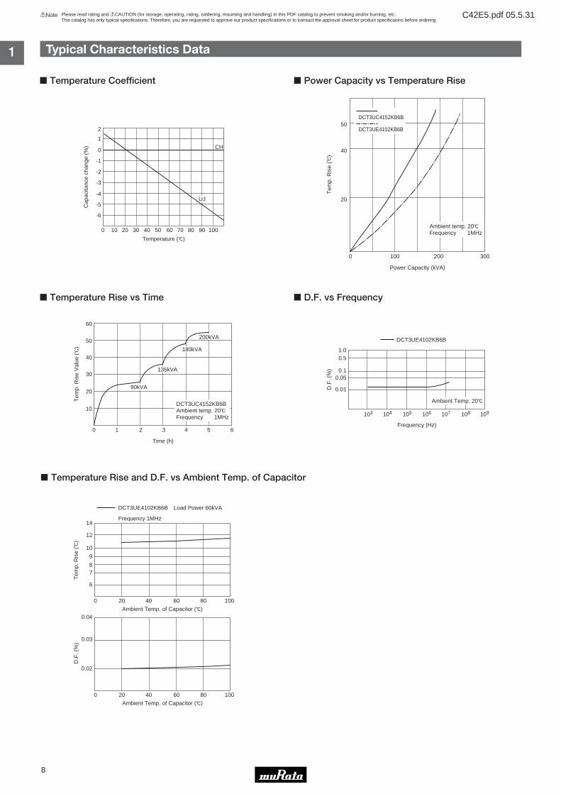
Typical Characteristics Data
! Temperature Coefficient
! Temperature Rise vs Time
2
1
0
-1
-2
-3
-4
-5
-6
0 10 20 30 40 50 60 70 80 90 100
Temperature (D)
Cap
acita
nce
chan
ge (
%)
UJ
CH
10
20
30
40
50
60
0 1 2 3 4 5 6
Time (h)
90kVA
135kVA
180kVA
200kVA
DCT3UC4152KB6BAmbient temp. 20DFrequency 1MHz
Tem
p. R
ise
Val
ue (D
)
6
78
9
10
12
14
0 20 40 60 80 100
Ambient Temp. of Capacitor (D)
DCT3UE4102KB6B Load Power 60kVA
Frequency 1MHz
0.02
0.03
0.04
0 20 40 60 80 100
Ambient Temp. of Capacitor (D)
Tem
p. R
ise
(D)
D.F
. (%
)! Power Capacity vs Temperature Rise
! D.F. vs Frequency
50
40
20
1000 200 300
Power Capacity (kVA)
DCT3UC4152KB6B
DCT3UE4102KB6B
Ambient temp. 20DFrequency 1MHz
Tem
p. R
ise
(D)
D.F
. (%
)
0.01
0.050.1
1.00.5
103 104 105 106 107 108 109
Frequency (Hz)
DCT3UE4102KB6B
Ambient Temp. 20D
! Temperature Rise and D.F. vs Ambient Temp. of Capacitor

!Note • Please read rating and !CAUTION (for storage, operating, rating, soldering, mounting and handling) in this catalog to prevent smoking and/or burning, etc. • This catalog has only typical specifications because there is no space for detailed specifications. Therefore, please approve our product specifications or transact the approval sheet for product specifications before ordering.
2
9
Small Type DC5 Series
High Frequency Power Ceramic Capacitors
øD
±0.8ø
1
H±0.830 min.
Shape Code C1, C3 <Fig. 1>
(in mm)
M2H±0.8
øD±0
.8
Shape Code C7 <Fig. 2>
(in mm)
M3 T±0.8H±2.0
øD±0
.8
Shape Code C6, C8 <Fig. 3>
(in mm)
M4
øDT
4.0
TT3.0HT6.0
Shape Code C5 <Fig. 5>
(in mm)
M4
øDT
2.0
TT1.0HT3.0
Shape Code C4 <Fig. 4>
(in mm)
! Features1. Most suitable in mobile equipment for rugged
construction, small size and light weight2. Very resistant to high voltage and power3. High "Q" and high insulation resistance4. Low series inductance with excellent frequency
performance5. No performance deterioration after extended
life–excellent humidity and thermal resistance
! Applications1. Radio communication equipment such as ships and
airplanes2. Small broadcasting equipment3. High frequency power supply for high frequency heating
equipment4. Various testing and measuring instruments5. Medical equipment (MRI)
! Marking1. Type Code2. Temperature Coefficient*3. Capacitance and Tolerance4. Rated Voltage (Vdc)5. Prod. Lot No.6. Manufacturer's Identification*Temperature Coefficients are expressed as follows:
Char. CH: NP0Char. UJ: N750Char. F: X5U

!Note Please read rating and !CAUTION (for storage, operating, rating, soldering, mounting and handling) in this PDF catalog to prevent smoking and/or burning, etc.This catalog has only typical specifications. Therefore, you are requested to approve our product specifications or to transact the approval sheet for product specificaions before ordering.
C42E5.pdf 05.5.31
UJ Characteristics
2
10
Part Number
RatedAllowable
Power(kVA)
Allowablemax.
Current(A [r.m.s.])
Dimensions (mm)Fig. No.
øD T H
TypeCode
Cap.(pF)
DCRated Volt.
(kV)
DCTest Volt.
(kV)
DC53U3H300KC1B
DC53U3H400KC1B
DC53U3E500KC1B
DC53U3H100KC7B
DC53UAD500KC6B
DC53UAD750KC6B
DC53U3H101KC6B
DC53U3H201KC6B
DC53U4C101KC4B
DC53UAD201KC4B
DC53U4D251KC5B
DC503
DC503
DC503
DC515
DC510
DC510
DC510
DC510
DC507
DC507
DC509
30
40
50
10
50
75
100
200
100
200
250
5
5
2.5
5
7.5
7.5
5
5
15
7.5
20
7.5
7.5
3.75
7.5
11.25
11.25
7.5
7.5
22.5
11.25
30
2.31
3.15
0.96
0.78
8.9
13.2
19
20.1
35
23
40
0.66
0.89
0.55
0.22
1.7
2.5
3.4
5.0
4.6
5.1
9.2
12
12
12
7.5
20
20
20
20
30
30
48
—
—
—
—
15.5
15.5
15.5
15.5
33
33
48
11
11
11
9.7
21
21
21
21
39
40
65
1
2
3
4
5
CH Characteristics
F Characteristics
Part Number
RatedAllowable
Power(kVA)
Allowablemax.
Current(A [r.m.s.])
Dimensions (mm)Fig. No.
øD T H
TypeCode
Cap.(pF)
DCRated Volt.
(kV)
DCTest Volt.
(kV)
Part Number
RatedAllowable
Power(kVA)
Allowablemax.
Current(A [r.m.s.])
Dimensions (mm)Fig. No.
øD T H
TypeCode
Cap.(pF)
DCRated Volt.
(kV)
DCTest Volt.
(kV)
DC52C3H030DC3B
DC52C3H050DC3B
DC52C3E100DC3B
DC52C3H100KC1B
DC52C3H200KC1B
DC52C3H050DC7B
DC52CAD150KC6B
DC52CAD250KC6B
DC52CAD300KC6B
DC52CAD400KC6B
DC52CAD500KC6B
DC52C4C250KC4B
DC52C4C500KC4B
DC505
DC505
DC505
DC505
DC505
DC515
DC510
DC510
DC510
DC510
DC510
DC507
DC507
5
5
2.5
5
5
5
7.5
7.5
7.5
7.5
7.5
15
15
7.5
7.5
3.75
7.5
7.5
7.5
11.25
11.25
11.25
11.25
11.25
22.5
22.5
0.23
0.38
0.19
0.78
1.55
0.38
4.0
5.0
5.7
5.6
8.9
18.5
35
0.07
0.11
0.11
0.22
0.44
0.11
0.61
0.89
1.0
1.38
1.7
1.7
3.3
6.3
6.3
6.3
12
12
7.5
20
20
20
20
20
30
30
—
—
—
—
—
—
15.5
15.5
15.5
15.5
15.5
33
33
8.5
8.5
8.5
11
11
9.7
21
21
21
21
21
41
38
1
2
3
4
3
5
10
10
20
5
15
25
30
40
50
25
50
DC5F33H501MC8B
DC5F33H102MC8B
DC518
DC518
500
1000
5
5
7.5
7.5
0.3
0.4
1.4
1.1
20
20
15.5
15.5
21
213

!Note Please read rating and !CAUTION (for storage, operating, rating, soldering, mounting and handling) in this PDF catalog to prevent smoking and/or burning, etc.This catalog has only typical specifications. Therefore, you are requested to approve our product specifications or to transact the approval sheet for product specificaions before ordering.
C42E5.pdf 05.5.31
2
11
Specifications and Test Methods
1
2
3
4
5
6
7
8
Operating Temperature Range
Capacitance
Temperature Characteristics
Quality Factor (Q)
Dissipation Factor (D.F.)
Dielectric Strength
Insulation Resistance (I.R.)
Strength of TorqueTerminal Strength
Power Capacity
-10 to +75˚C
Within the specified tolerance
Temperature coefficientChar. CH: 0±60ppm/˚CChar. UJ: -750±120ppm/˚CChar. F: +30%/-80%
Char. CH, UJ: 400+200C* min.(30pF under)
: 1000 min.(30pF min.)
Char. F: 5.0% max.
No failure
10000MΩ min.
Capacitor should not be broken.
30˚C max.
—
The capacitance should be measured at 20°C with 1±0.1MHz (Char. F:1±0.1kHz) and AC5V(r.m.s.) max.
The capacitance measurement should be made at each step specifiedin table.Capacitance change from the value of step 3 should not exceed thelimit specified.
The quality factor and dissipation factor should be measured at 20°Cwith 1±0.1MHz (Char. F: 1±0.1kHZ) and AC5V(r.m.s.) max.
The capacitor should not be damaged when DC voltage of 150% of therated voltage is applied between the terminal for 60±5 sec.
The insulation resistance should be measured with DC1000V within60±5 sec. of charging.
The capacitor should not be damaged when the torque shown in thetable below is applied to the terminals.
The rise of temperature at the terminals should be measured at 20°Cwith 1±0.1MHz and the rated allowable power when the temperature ateach section has been stabilized.
No. Item Specifications Test Method
* "C" expresses nominal capacitance value (pF)
Terminal TypeISO-M2ISO-M3ISO-M4
Torque (N·m)0.390.491.2
120±2
2-25±3
320±2
485±2
520±2
StepTemp. (°C)

!Note Please read rating and !CAUTION (for storage, operating, rating, soldering, mounting and handling) in this PDF catalog to prevent smoking and/or burning, etc.This catalog has only typical specifications. Therefore, you are requested to approve our product specifications or to transact the approval sheet for product specificaions before ordering.
C42E5.pdf 05.5.31
! !Caution (Rating)1. Operating Voltage
When DC-rated capacitors are to be used in AC or ripplecurrent circuits, be sure to maintain the Vp-p value of theapplied voltage or the Vo-p which contains DC bias withinthe rated voltage range. When the voltage is applied to the circuit, starting orstopping may generate irregular voltage for a transitperiod because of resonance or switching. Be sure touse a capacitor with a rated voltage range that includesthese irregular voltages.
2. Operating Temperature and Self-generated HeatKeep the surface temperature of a capacitor below theupper limit of its rated operating temperature range. Besure to take into account the heat generated by thecapacitor itself. When the capacitor is used in a highfrequency current, it may self-generate heat due todielectric loss. The applied voltage load should be suchthat the capacitor's self-generated heat is within 10°C (incase of temperature characteristic F and within 20°C) atan atmosphere temperature of 25°C. Excessive heat maylead to deterioration of the capacitor's characteristics andreliability. (Never attempt to perform measurement withthe cooling fan running. Otherwise, accuratemeasurement cannot be ensured.)
! !Caution (Storage and Operation Condition)Operating and storage environment
The insulating coating of capacitors does not form aperfect seal; therefore, do not use or store capacitors in acorrosive atmosphere, especially where chloride gas,sulfide gas, acid, alkali, salt or the like are present. Andavoid exposure to moisture.Avoid a dusty place. Otherwise, surface corona dischargeand flashover may occur.Store the capacitors where the temperature and relativehumidity do not exceed -10 to 40 degrees centigrade and15 to 85%. Use capacitors within 6 months.
12
!Caution/Notice
Voltage
Positional Measurement
DC Voltage DC+AC Voltage AC Voltage Pulse Voltage (1) Pulse Voltage (2)
V0-p V0-p Vp-p Vp-p Vp-p
!Note Please read rating and !CAUTION (for storage, operating, rating, soldering, mounting and handling) in this PDF catalog to prevent smoking and/or burning, etc.This catalog has only typical specifications. Therefore, you are requested to approve our product specifications or to transact the approval sheet for product specificaions before ordering.
C42E5.pdf 05.5.31
13
!Caution/Notice
! !Caution (Soldering and Mounting)1. Installation (Except for DC5 Series/Shape code: C1, C3)
Installation torque should not exceed the torque strengthvalues in "Specifications and Test Methods".Do not use a screw with a thread depth greater thanspecified.Avoid installation in which any bending torque is appliedto the capacitor terminal.Do not fix the product body with only one terminal. (Avoidcantilever mounting.) Do not rework or solder theterminals.
2. Soldering (DC5 Series/Shape code: C1, C3)When soldering this product to a PCB/PWB, do not
exceed the solder heat resistance specification of thecapacitor. Subjecting this product to excessive heatingcould melt the internal junction solder and may result inthermal shocks that can crack the ceramic element.When soldering capacitor with a soldering iron, it shouldbe performed in following conditions.
Soldering method: Soldering ironSoldering temperature: 270°C max.Soldering time: 3 sec. max.*Solder the lead terminals at 3mm or longer distancefrom their roots.
! !Caution (Handling)Vibration and impact
Since this product is made of ceramics, applying impact(drop impact, etc.) to the product results in breakage orflaws of elements. Do not transport the product with theproduct being mounted to the set.Otherwise, the terminal strength may be deteriorated dueto impact or vibration.
FAILURE TO FOLLOW THE ABOVE CAUTIONS MAYRESULT, WORST CASE, IN A SHORT CIRCUIT ANDCAUSE FUMING OR PARTIAL DISPERSION WHEN THEPRODUCT IS USED.
! Notice (Rating)Capacitance change of capacitor1. Class 1 capacitors
Capacitance might change a little depending on thesurrounding temperature or an applied voltage.Please contact us if you intend to use this product in astrict time constant circuit.
2. Class 2 and 3 capacitorsClass 2 and 3 capacitors with temperature characteristicsB, E and F have an aging characteristic, whereby thecapacitor continually decreases its capacitance slightly ifthe capacitor is left on for a long time. Moreover,capacitance might change greatly depending on thesurrounding temperature or an applied voltage. So, it isnot likely to be suitable for use in a time constant circuit.Please contact us if you need detailed information.

Note:1. Export Control
<For customers outside Japan>Murata products should not be used or sold for use in the development, production, stockpiling or utilization of any conventional weapons or mass-destructiveweapons (nuclear weapons, chemical or biological weapons, or missiles), or any other weapons.<For customers in Japan>For products which are controlled items subject to the “Foreign Exchange and Foreign Trade Law” of Japan, the export license specified by the law is requiredfor export.
2. Please contact our sales representatives or product engineers before using the products in this catalog for the applications listed below, which require especiallyhigh reliability for the prevention of defects which might directly damage to a third party's life, body or property, or when one of our products is intended for usein applications other than those specified in this catalog.q Aircraft equipment w Aerospace equipmente Undersea equipment r Power plant equipmentt Medical equipment y Transportation equipment (vehicles, trains, ships, etc.)u Traffic signal equipment i Disaster prevention / crime prevention equipmento Data-processing equipment !0 Application of similar complexity and/or reliability requirements to the applications listed in the above
3. Product specifications in this catalog are as of May 2005. They are subject to change or our products in it may be discontinued without advance notice. Pleasecheck with our sales representatives or product engineers before ordering. If there are any questions, please contact our sales representatives or productengineers.
4. Please read rating and CAUTION (for storage, operating, rating, soldering, mounting and handling) in this catalog to prevent smoking and/or burning, etc.
5. This catalog has only typical specifications because there is no space for detailed specifications. Therefore, please approve our product specifications ortransact the approval sheet for product specifications before ordering.
6. Please note that unless otherwise specified, we shall assume no responsibility whatsoever for any conflict or dispute that may occur in connection with the effectof our and/or a third party's intellectual property rights and other related rights in consideration of your use of our products and/or information described orcontained in our catalogs. In this connection, no representation shall be made to the effect that any third parties are authorized to use the rights mentionedabove under licenses without our consent.
7. No ozone depleting substances (ODS) under the Montreal Protocol are used in our manufacturing process.
International Division3-29-12, Shibuya, Shibuya-ku, Tokyo 150-0002, Japan Phone: 81-3-5469-6123 Fax: 81-3-5469-6155 E-mail: [email protected]
Head Office1-10-1, Higashi Kotari, Nagaokakyo-shi, Kyoto 617-8555, JapanPhone: 81-75-951-9111
http://www.murata.com/
!Note Please read rating and !CAUTION (for storage, operating, rating, soldering, mounting and handling) in this PDF catalog to prevent smoking and/or burning, etc.This catalog has only typical specifications. Therefore, you are requested to approve our product specifications or to transact the approval sheet for product specificaions before ordering.
C42E5.pdf 05.5.31