Embed Size (px)
DESCRIPTION
MANUAL
Citation preview

Gas Panel and High Frequency Console
Instruction Manual802960 – Revision 2
Integrated Plasma SystemFor use with the TM
HT2000®

NOTICE
Use the HT2000 instruction manual, 802070, as well as this manual, 802960, to install, operateand maintain the HT2000 with Titan system.
• This manual contains information to install and operate the HT2000 with Titan system. Aparts list for the gas panel and high frequency console is also included.
• See the 802070 manual for general maintenance and information relevant to the HT2000power supply and accessories.


HT2000
Gas Panel and High Frequency Consolefor
Instruction Manual(P/N 802960)
Revision 2 – April, 2001
© Copyright 2001 Hypertherm, Inc.All Rights Reserved
Hypertherm, HT, HyLife, and LongLife are trademarks of Hypertherm, Inc. and may be registered in the United States and/or other countries
Hypertherm, Inc.Hanover, NH USA
www.hypertherm.com

Hypertherm, Inc.
Etna Road, P.O. Box 5010Hanover, NH 03755 USA603-643-3441 Tel (Main Office)603-643-5352 Fax (All Departments)800-643-9878 Tel (Technical Service)800-737-2978 Tel (Customer Service)
Hypertherm Automation
5 Technology DriveWest Lebanon, NH 03755 USA603-298-7970 Tel 603-298-7977 Fax
Hypertherm Plasmatechnik GmbH
Technologiepark HanauRodenbacher Chaussee 6 63457 Hanau-Wolfgang, Deutschland49 6181 58 2100 Tel 49 6181 58 2134 Fax49 6181 58 2123 (Technical Service)
Hypertherm Singapore Pte Ltd
No. 19 Kaki Bukit Road 2 K.B. Warehouse Complex Singapore 417847, Republic of Singapore65 6 841 2489 Tel 65 6 841 2490 Fax 65 6 841 2489 (Technical Service)
Japan
1952-14 Yata-NatsumegiMishima City, Shizuoka Pref.411-0801 Japan81 0 559 75 7387 Tel81 0 559 75 7376 Fax
Hypertherm UK Ltd
9 Berkeley Court, Manor Park Runcorn, Cheshire, England WA7 1TQ44 1928 579 074 Tel 44 1928 579 604 Fax
France
15 Impasse des Rosiers95610 Eragny, France00 800 3324 9737 Tel 00 800 4973 7329 Fax
Hypertherm S.r.L.
Via Torino 220123 Milano, Italia39 02 725 46 312 Tel 39 02 725 46 400 Fax39 02 725 46 314 (Technical Service)
Hypertherm Europe B.V.
Vaartveld 94704 SE Roosendaal, Nederland31 165 596908 Tel 31 165 596901 Fax
Hypertherm B.V. (ETSO)
Vaartveld 94704 SE Roosendaal, Nederland00 800 49 73 7843 – toll-free in Europe
31 165 596900 Tel31 165 596901 Fax
Hypertherm Brasil Ltda.
Rua Visconde de Santa Isabel, 20 – Sala 611Vila Isabel, RJ Brasil CEP 20560-12055 21 2278 6162 Tel55 21 2578 0947 Fax
2/12/03

ELECTROMAGNETIC COMPATIBILITY (EMC)
EMC INTRODUCTION
Hypertherm's CE-marked equipment is builtin compliance with standard EN50199. Theequipment should be installed and used inaccordance with the information below toachieve electromagnetic compatibility.
The limits required by EN50199 may not beadequate to completely eliminate interfer-ence when the affected equipment is inclose proximity or has a high degree ofsensitivity. In such cases it may be neces-sary to use other measures to furtherreduce interference.
This plasma equipment is designed for useonly in an industrial environment.
INSTALLATION AND USE
The user is responsible for installing andusing the plasma equipment according tothe manufacturer's instructions. If electro-magnetic disturbances are detected then itshall be the responsibility of the user to re-solve the situation with the technical assis-tance of the manufacturer. In some casesthis remedial action may be as simple asearthing the cutting circuit, see Earthing ofWorkpiece. In other cases it could involveconstructing an electromagnetic screenenclosing the power source and the workcomplete with associated input filters. In allcases electromagnetic disturbances mustbe reduced to the point where they are nolonger troublesome.
ASSESSMENT OF AREA
Before installing the equipment the usershall make an assessment of potential elec-tromagnetic problems in the surroundingarea. The following shall be taken intoaccount:a. Other supply cables, control cables,signalling and telephone cables; above,below and adjacent to the cutting equip-ment.b. Radio and television transmitters andreceivers.c. Computer and other control equipment.d. Safety critical equipment, for exampleguarding of industrial equipment.e. Health of the people around, for example the use of pacemakers and hear-ing aids.f. Equipment used for calibration or mea-surement.g. Immunity of other equipment in the en-vironment. User shall ensure that otherequipment being used in the environment iscompatible. This may require additionalprotection measures.h. Time of day that cutting or other activitiesare to be carried out.
Earthing of Workpiece
Where the workpiece is not bonded to earthfor electrical safety, nor connected to earthbecause of its size and position, for example,ship's hull or building steelwork, a connectionbonding the workpiece to earth may reduceemissions in some, but not all instances.Care should be taken to prevent the earthingof the workpiece increasing the risk of injuryto users, or damage to other electrical equip-ment. Where necessary, the connection ofthe workpiece to earth should be made by adirect connection to the workpiece, but insome countries where direct connection isnot permitted, the bonding should beachieved by suitable capacitances selectedaccording to national regulations.
Note. The cutting circuit may or may not beearthed for safety reasons. Changing theearthing arrangements should only be au-thorized by a person who is competent toassess whether the changes will increasethe risk of injury, for example, by allowingparallel cutting current return paths whichmay damage the earth circuits of otherequipment. Further guidance is given in IECTC26 (sec)94 and IEC TC26/108A/CD ArcWelding Equipment Installation and Use.
Screening and Shielding
Selective screening and shielding of othercables and equipment in the surroundingarea may alleviate problems of interference.Screening of the entire plasma cuttinginstallation may be considered for specialapplications
The size of the surrounding area to beconsidered will depend on the structure ofthe building and other activities that are tak-ing place. The surrounding area may extendbeyond the boundaries of the premises.
METHODS OF REDUCING EMISSIONS
Mains Supply
Cutting equipment must be connected to themains supply according to the manufactur-er's recommendations. If interferenceoccurs, it may be necessary to takeadditional precautions such as filtering ofthe mains supply. Consideration should begiven to shielding the supply cable of per-manently installed cutting equipment, inmetallic conduit or equivalent. Shieldingshould be electrically continuous throughoutits length. The shielding should be connect-ed to the cutting mains supply so that goodelectrical contact is maintained between theconduit and the cutting power sourceenclosure
Maintenance of Cutting Equipment
The cutting equipment must be routinelymaintained according to the manufacturer'srecommendations. All access and servicedoors and covers should be closed andproperly fastened when the cuttingequipment is in operation. The cuttingequipment should not be modified in anyway except for those changes and adjust-ments covered in the manufacturer'sinstructions. In particular, the spark gaps ofarc striking and stabilizing devices shouldbe adjusted and maintained according tothe manufacturer's recommendations.
Cutting Cables
The cutting cables should be kept as shortas possible and should be positioned closetogether, running at or close to the floorlevel.
Equipotential Bonding
Bonding of all metallic components in thecutting installation and adjacent to it shouldbe considered. However, metallic compo-nents bonded to the workpiece will increasethe risk that the operator could receive ashock by touching these metalliccomponents and the electrode at the sametime. The operator should be insulated fromall such bonded metallic components.
Hypertherm Plasma Systems i

WARRANTY
ii Hypertherm Plasma Systems9-01
WARNINGGenuine Hypertherm parts are the factory-recommendedreplacement parts for your Hypertherm system. Any damagecaused by the use of other than genuine Hypertherm parts maynot be covered by the Hypertherm warranty.
WARNINGYou are responsible for the safe use of the Product.Hypertherm does not and cannot make any guarantee orwarranty regarding the safe use of the Product in yourenvironment.
GENERALHypertherm, Inc. warrants that its Products shall be free fromdefects in materials and workmanship, if Hypertherm is notifiedof a defect (i) with respect to the power supply within a periodof two (2) years from the date of its delivery to you, with theexception of G3 Series power supplies, which shall be within aperiod of three (3) years from the date of delivery to you, and(ii) with respect to the torch and leads within a period of one (1)year from its date of delivery to you. This warranty shall notapply to any Product which has been incorrectly installed,modified, or otherwise damaged. Hypertherm, at its soleoption, shall repair, replace, or adjust, free of charge, anydefective Products covered by this warranty which shall bereturned with Hypertherm’s prior authorization (which shall notbe unreasonably withheld), properly packed, to Hypertherm’splace of business in Hanover, New Hampshire, or to anauthorized Hypertherm repair facility, all costs, insurance andfreight prepaid. Hypertherm shall not be liable for any repairs,replacement, or adjustments of Products covered by thiswarranty, except those made pursuant to this paragraph or withHypertherm’s prior written consent. The warranty above isexclusive and is in lieu of all other warranties, express,implied, statutory, or otherwise with respect to theProducts or as to the results which may be obtainedtherefrom, and all implied warranties or conditions ofquality or of merchantability or fitness for a particularpurpose or against infringement. The foregoing shallconstitute the sole and exclusive remedy for any breachby Hypertherm of its warranty. Distributors/OEMs may offerdifferent or additional warranties, but Distributors/OEMs arenot authorized to give any additional warranty protection to youor make any representation to you purporting to be bindingupon Hypertherm.
PATENT INDEMNITYExcept only in cases of products not manufactured byHypertherm or manufactured by a person other thanHypertherm not in strict conformity with Hypertherm’sspecifications and in cases of designs, processes, formulae, orcombinations not developed or purported to be developed byHypertherm, Hypertherm will defend or settle, at its ownexpense, any suit or proceeding brought against you allegingthat the use of the Hypertherm product, alone and not incombination with any other product not supplied by
Hypertherm, infringes any patent of any third party. You shallnotify Hypertherm promptly upon learning of any action orthreatened action in connection with any such allegedinfringement, and Hypertherm’s obligation to indemnify shall beconditioned upon Hypertherm’s sole control of, and theindemnified party’s cooperation and assistance in, the defenseof the claim.
LIMITATION OF LIABILITYIn no event shall Hypertherm be liable to any person orentity for any incidental, consequential, indirect, orpunitive damages (including but not limited to lost profits)regardless of whether such liability is based on breach ofcontract, tort, strict liability, breach of warranties, failure ofessential purpose or otherwise and even if advised of thepossibility of such damages.
LIABILITY CAPIn no event shall Hypertherm’s liability, whether suchliability is based on breach of contract, tort, strict liability,breach of warranties, failure of essential purpose orotherwise, for any claim action suit or proceeding arisingout of or relating to the use of the Products exceed in theaggregate the amount paid for the Products that gave riseto such claim.
INSURANCEAt all times you will have and maintain insurance in suchquantities and types, and with coverage sufficient andappropriate to defend and to hold Hypertherm harmless in the event of any cause of action arising from the use of theProducts.
NATIONAL AND LOCAL CODESNational and Local codes governing plumbing and electricalinstallation shall take precedent over any instructionscontained in this manual. In no event shall Hypertherm beliable for injury to persons or property damage by reason of anycode violation or poor work practices.
TRANSFER OF RIGHTSYou may transfer any remaining rights you may havehereunder only in connection with the sale of all or substantiallyall of your assets or capital stock to a successor in interest whoagrees to be bound by all of the terms and conditions of thisWarranty.

HT2000 with Titan Instruction Manual iii
Electromagnetic Compatibility (EMC).......................................................................................................................iWarranty .....................................................................................................................................................................ii
Section 1 SAFETY..................................................................................................................................................1-1Recognize Safety Information...................................................................................................................................1-2Follow Safety Instructions.........................................................................................................................................1-2Cutting Can Cause Fire or Explosion .......................................................................................................................1-2Electric Shock Can Kill..............................................................................................................................................1-3Cutting Can Produce Toxic Fumes...........................................................................................................................1-3A Plasma Arc Can Cause Injury and Burns..............................................................................................................1-4Arc Rays Can Burn Eyes and Skin ...........................................................................................................................1-4Grounding Safety......................................................................................................................................................1-4Compressed Gas Equipment Safety ........................................................................................................................1-5Gas Cylinders Can Explode If Damaged ..................................................................................................................1-5Noise Can Damage Hearing.....................................................................................................................................1-5Pacemaker and Hearing Aid Operation ....................................................................................................................1-5A Plasma Arc Can Damage Frozen Pipes................................................................................................................1-5Additional Safety Information....................................................................................................................................1-5Warning Label...........................................................................................................................................................1-6
Section 1a SÉCURITÉ........................................................................................................................................1a-1Identifier les consignes de sécurité.........................................................................................................................1a-2Suivre les instructions de sécurité ..........................................................................................................................1a-2Le coupage peut provoquer un incendie ou une explosion ....................................................................................1a-2Les chocs électriques peuvent être fatals...............................................................................................................1a-3Le coupage peut produire des vapeurs toxiques....................................................................................................1a-3L'arc plasma peut provoquer des blessures ou des brûlures .................................................................................1a-4Mise à la masse et à la terre...................................................................................................................................1a-4Les rayons de l'arc peuvent brûler les yeux et la peau...........................................................................................1a-4Sécurité des bouteilles de gaz comprimé ...............................................................................................................1a-5Les bouteilles de gaz comprimé peuvent exploser en cas de dommages .............................................................1a-5Le bruit peut provoquer des problèmes auditifs......................................................................................................1a-5Pacemakers et prothéses auditives........................................................................................................................1a-5Étiquette de sécurité ...............................................................................................................................................1a-6
Section 2 SPECIFICATIONS................................................................................................................................2-1System Components ................................................................................................................................................2-1
Power Supply ..................................................................................................................................................2-1HT2000 Machine Torch....................................................................................................................................2-1Remote High Frequency&Motor Valve Console (also called “High Frequency Console”) ...............................2-1Gas Panel ........................................................................................................................................................2-1Timer/Counter – Optional.................................................................................................................................2-1Water Muffler – Optional ..................................................................................................................................2-1
Specifications............................................................................................................................................................2-2System Requirements......................................................................................................................................2-2HT2000 Power Supply .....................................................................................................................................2-2HT2000 Machine Torch....................................................................................................................................2-3Remote High Frequency and Motor Valve (RHF&MV) Console ......................................................................2-3Gas Panel ........................................................................................................................................................2-4

TABLE OF CONTENTS
iv HT2000 with Titan Instruction Manual
Section 3 INSTALLATION ...................................................................................................................................3-1Pre-Installation..........................................................................................................................................................3-1System Units Placement...........................................................................................................................................3-1Power Supply Connections.......................................................................................................................................3-4Gas Panel Connections ............................................................................................................................................3-7RH&MV Console to Torch Connections ...................................................................................................................3-9
Routing the Torch Leads..................................................................................................................................3-9Connecting the Torch Leads to the Torch........................................................................................................3-9
Mounting the Machine Torch ..................................................................................................................................3-12Torch Alignment ............................................................................................................................................3-12
Section 4 INSTALLATION ...................................................................................................................................4-1Front Panel Controls and Indicators .........................................................................................................................4-2
HT2000 Titan Gas Panel (Fig. 4-1) ..................................................................................................................4-2Daily Start-up ............................................................................................................................................................4-3
Check Torch ....................................................................................................................................................4-3Turn Gases On.................................................................................................................................................4-3Turn Power Supply On and Adjust Voltage/Current.........................................................................................4-4Adjust Preflow Gases.......................................................................................................................................4-4Adjust Cut Flow Gases and Prepare for Cutting ..............................................................................................4-4
Common Cutting Faults ............................................................................................................................................4-5Technical Questions .................................................................................................................................................4-5Cut Charts.................................................................................................................................................................4-5Conversions..............................................................................................................................................................4-5Mild Steel ..................................................................................................................................................................4-7
200 amps • Air Plasma / Air Shield ................................................................................................................4-7Mild Steel ..................................................................................................................................................................4-8
200 amps • O2 Plasma / Air Shield.................................................................................................................4-8Mild Steel ..................................................................................................................................................................4-9
200 amps • N2 Plasma / CO2 Shield...............................................................................................................4-9Mild Steel ................................................................................................................................................................4-10
100* amps • Air Plasma / Air Shield .............................................................................................................4-10Mild Steel ................................................................................................................................................................4-11
100 amps • O2 Plasma / Air Shield...............................................................................................................4-11Mild Steel ................................................................................................................................................................4-12
50 amps • O2 Plasma / O2 Shield .................................................................................................................4-12Stainless Steel ........................................................................................................................................................4-13
200 amps • Air Plasma / Air Shield ..............................................................................................................4-13Stainless Steel ........................................................................................................................................................4-14
200 amps • N2 Plasma / Air Shield...............................................................................................................4-14Stainless Steel ........................................................................................................................................................4-15
200 amps • N2 Plasma / CO2 Shield.............................................................................................................4-15Stainless Steel ........................................................................................................................................................4-16
200 amps • H35 Plasma / N2 Shield.............................................................................................................4-16Stainless Steel ........................................................................................................................................................4-17
100 amps • Air Plasma / Air Shield ..............................................................................................................4-17

TABLE OF CONTENTS
HT2000 with Titan Instruction Manual v
Stainless Steel ........................................................................................................................................................4-18100 amps • H35 Plasma / N2 Shield.............................................................................................................4-18
Stainless Steel ........................................................................................................................................................4-1940 amps • Air Plasma / Air Shield ................................................................................................................4-19
Aluminum................................................................................................................................................................4-20200 amps • Air Plasma / Air Shield ..............................................................................................................4-20
Aluminum................................................................................................................................................................4-21200 amps • N2 Plasma / Air Shield...............................................................................................................4-21
Aluminum................................................................................................................................................................4-22200 amps • N2 Plasma / CO2 Shield.............................................................................................................4-22
Aluminum................................................................................................................................................................4-23200 amps • H35 Plasma / N2 Shield.............................................................................................................4-23
Aluminum................................................................................................................................................................4-24100 amps • Air Plasma / Air Shield ..............................................................................................................4-24
Aluminum................................................................................................................................................................4-25100 amps • H35 Plasma / N2 Shield.............................................................................................................4-25
Aluminum................................................................................................................................................................4-2640 amps • Air Plasma / Air Shield ................................................................................................................4-26
Mild Steel - Beveling Consumables ........................................................................................................................4-27200 amps • O2 Plasma / Air Shield...............................................................................................................4-27
Stainless Steel or Aluminum Gouging ....................................................................................................................4-28200 amps • H35 Plasma / N2 Shield.............................................................................................................4-28
Mild Steel Gouging .................................................................................................................................................4-28200 amps • Air Plasma / Air Shield ..............................................................................................................4-28
Changing Consumable Parts..................................................................................................................................4-29Removal and Inspection – Refer to Figure 4-2 ..............................................................................................4-29Replacement ..................................................................................................................................................4-30Changing the Water Tube ..............................................................................................................................4-31
Section 5 PARTS LIST..........................................................................................................................................5-1Gas Panel – 073220 .................................................................................................................................................5-3RHF&MV Console – 073223 ....................................................................................................................................5-5HT2000 Standard Machine Torch Assembly with Valve,
2" (50 mm) Dia. Torch Sleeve, and 25' (7.6 m) Leads – 128383..........................................................................5-7HT2000 Stainless Steel Machine Torch Assembly with Valve,
2" (50 mm) Dia. Torch Sleeve, and 25' (7.6 m) Leads – 128368..........................................................................5-7Torch Mounting Bracket for 2" (50 mm) Dia. Torch Sleeve – 020046 ......................................................................5-7HT2000 Optional Machine Torch Assembly with Valve,
1-3/4" (44 mm) Dia. Torch Sleeve, and 25' (7.6 m) Leads – 128200....................................................................5-9Torch Mounting Bracket for 1-3/4” (44 mm) Dia. Torch Sleeve – 020522 ................................................................5-9Consumable Parts Kit – 028602 .............................................................................................................................5-10
Section 6 WIRING DIAGRAMS............................................................................................................................6-1Introduction ...............................................................................................................................................................6-1Wiring Diagram Symbols ..........................................................................................................................................6-1HT2000 System Wiring Diagrams ............................................................................................................................6-5

TABLE OF CONTENTS
vi HT2000 with Titan Instruction Manual

Hypertherm Plasma Systems 1-1
Section 1
SAFETY
In this section:
Recognize Safety Information .........................................................................................................................1-2Follow Safety Instructions ...............................................................................................................................1-2Cutting Can Cause Fire or Explosion..............................................................................................................1-2Electric Shock Can Kill ....................................................................................................................................1-3Cutting Can Produce Toxic Fumes..................................................................................................................1-3A Plasma Arc Can Cause Injury and Burns.....................................................................................................1-4Arc Rays Can Burn Eyes and Skin .................................................................................................................1-4Grounding Safety ............................................................................................................................................1-4Compressed Gas Equipment Safety...............................................................................................................1-5Gas Cylinders Can Explode If Damaged ........................................................................................................1-5Noise Can Damage Hearing ...........................................................................................................................1-5Pacemaker and Hearing Aid Operation...........................................................................................................1-5A Plasma Arc Can Damage Frozen Pipes ......................................................................................................1-5Additional Safety Information ..........................................................................................................................1-5Warning Label .................................................................................................................................................1-6

SAFETY
1-2 Hypertherm Plasma Systems11-98
SAFETY
RECOGNIZE SAFETY INFORMATION
The symbols shown in this section are used toidentify potential hazards. When you see a safetysymbol in this manual or on your machine, understandthe potential for personal injury, and follow the relatedinstructions to avoid the hazard.
FOLLOW SAFETY INSTRUCTIONS
Read carefully all safety messages in this manual andsafety labels on your machine.
• Keep the safety labels on your machine in goodcondition. Replace missing or damaged labelsimmediately.
• Learn how to operate the machine and how to use the controls properly. Do not let anyone operate itwithout instruction.
• Keep your machine in proper working condition.Unauthorized modifications to the machine mayaffect safety and machine service life.
DANGER WARNING CAUTION
A signal word DANGER or WARNING is used with asafety symbol. DANGER identifies the most serioushazards.
• DANGER and WARNING safety labels are locatedon your machine near specific hazards.
• WARNING safety messages precede relatedinstructions in this manual that may result in injuryor death if not followed correctly.
• CAUTION safety messages precede relatedinstructions in this manual that may result indamage to equipment if not followed correctly.
Fire Prevention• Be sure the area is safe before doing any cutting.
Keep a fire extinguisher nearby.• Remove all flammables within 35 feet (10 m) of the
cutting area.• Quench hot metal or allow it to cool before handling
or before letting it touch combustible materials.• Never cut containers with potentially flammable
materials inside – they must be emptied andproperly cleaned first.
• Ventilate potentially flammable atmospheres beforecutting.
• When cutting with oxygen as the plasma gas, anexhaust ventilation system is required.
Explosion Prevention• Do not use the plasma system if explosive dust or
vapors may be present.• Do not cut pressurized cylinders, pipes, or any
closed container.• Do not cut containers that have held combustible
materials.
CUTTING CAN CAUSE FIRE OR EXPLOSION
WARNING
Explosion HazardArgon-Hydrogen and Methane
Hydrogen and methane are flammable gases thatpresent an explosion hazard. Keep flames away fromcylinders and hoses that contain methane or hydrogenmixtures. Keep flames and sparks away from the torchwhen using methane or argon-hydrogen plasma.
WARNING
Hydrogen Detonation with Aluminum Cutting
• When cutting aluminum underwater, or with thewater touching the underside of the aluminum, freehydrogen gas may collect under the workpiece anddetonate during plasma cutting operations.
• Install an aeration manifold on the floor of the watertable to eliminate the possibility of hydrogendetonation. Refer to the Appendix section of thismanual for aeration manifold details.

Touching live electrical parts can cause a fatal shockor severe burn.
• Operating the plasma system completes anelectrical circuit between the torch and theworkpiece. The workpiece and anything touchingthe workpiece are part of the electrical circuit.
• Never touch the torch body, workpiece or the waterin a water table when the plasma system isoperating.
Electric Shock Prevention
All Hypertherm plasma systems use high voltagein the cutting process (200 to 400 VDC arecommon). Take the following precautions whenoperating this system:• Wear insulated gloves and boots, and keep your
body and clothing dry.• Do not stand, sit or lie on – or touch – any wet
surface when using the plasma system.• Insulate yourself from work and ground using dry
insulating mats or covers big enough to prevent anyphysical contact with the work or ground. If you mustwork in or near a damp area, use extreme caution.
• Provide a disconnect switch close to the powersupply with properly sized fuses. This switch allowsthe operator to turn off the power supply quickly inan emergency situation.
• When using a water table, be sure that it is correctlyconnected to earth ground.
ELECTRIC SHOCK CAN KILL
• Install and ground this equipment according to theinstruction manual and in accordance with nationaland local codes.
• Inspect the input power cord frequently for damageor cracking of the cover. Replace a damaged powercord immediately. Bare wiring can kill.
• Inspect and replace any worn or damaged torchleads.
• Do not pick up the workpiece, including the wastecutoff, while you cut. Leave the workpiece in placeor on the workbench with the work cable attachedduring the cutting process.
• Before checking, cleaning or changing torch parts,disconnect the main power or unplug the powersupply.
• Never bypass or shortcut the safety interlocks.• Before removing any power supply or system
enclosure cover, disconnect electrical input power.Wait 5 minutes after disconnecting the main powerto allow capacitors to discharge.
• Never operate the plasma system unless the powersupply covers are in place. Exposed power supplyconnections present a severe electrical hazard.
• When making input connections, attach propergrounding conductor first.
• Each Hypertherm plasma system is designed to beused only with specific Hypertherm torches. Do notsubstitute other torches which could overheat andpresent a safety hazard.
Cutting can produce toxic fumes and gases thatdeplete oxygen and cause injury or death.
• Keep the cutting area well ventilated or use anapproved air-supplied respirator.
• Do not cut in locations near degreasing, cleaning orspraying operations. The vapors from certainchlorinated solvents decompose to form phosgenegas when exposed to ultraviolet radiation.
• Do not cut metal coated or containing toxic materi-als, such as zinc (galvanized), lead, cadmium or
CUTTING CAN PRODUCE TOXIC FUMES
beryllium, unless the area is well ventilated and theoperator wears an air-supplied respirator. Thecoatings and any metals containing these elementscan produce toxic fumes when cut.
• Never cut containers with potentially toxic materialsinside – they must be emptied and properly cleanedfirst.
• This product, when used for welding or cutting,produces fumes or gases which contain chemicalsknown to the State of California to cause birthdefects and, in some cases, cancer.
Hypertherm Plasma Systems 1-38-99
SAFETY

SAFETY
1-4 Hypertherm Plasma Systems5/6/02
SAFETY
Instant-On TorchesPlasma arc comes on immediately when the torchswitch is activated.
A PLASMA ARC CAN CAUSE INJURY AND BURNS
The plasma arc will cut quickly through gloves andskin.• Keep away from the torch tip.• Do not hold metal near the cutting path.• Never point the torch toward yourself or others.
Eye Protection Plasma arc rays produce intensevisible and invisible (ultraviolet and infrared) rays thatcan burn eyes and skin.• Use eye protection in accordance with applicable
national or local codes.• Wear eye protection (safety glasses or goggles with
side shields, and a welding helmet) with appropriatelens shading to protect your eyes from the arc’sultraviolet and infrared rays.
Lens ShadeArc Current AWS (USA) ISO 4850
Up to 100 A No. 8 No. 11100-200 A No. 10 No. 11-12200-400 A No. 12 No. 13Over 400 A No. 14 No. 14
ARC RAYS CAN BURN EYES AND SKIN
Skin Protection Wear protective clothing to protectagainst burns caused by ultraviolet light, sparks andhot metal.• Gauntlet gloves, safety shoes and hat.• Flame-retardant clothing to cover all exposed areas.• Cuffless trousers to prevent entry of sparks and
slag.• Remove any combustibles, such as a butane lighter
or matches, from your pockets before cutting.
Cutting Area Prepare the cutting area to reducereflection and transmission of ultraviolet light:• Paint walls and other surfaces with dark colors to
reduce reflection. • Use protective screens or barriers to protect others
from flash and glare.• Warn others not to watch the arc. Use placards or
signs.
Work Cable Attach the work cable securely to theworkpiece or the work table with good metal-to-metalcontact. Do not connect it to the piece that will fallaway when the cut is complete.
Work Table Connect the work table to an earthground, in accordance with appropriate national orlocal electrical codes.
GROUNDING SAFETY Input Power• Be sure to connect the power cord ground wire to
the ground in the disconnect box.• If installation of the plasma system involves
connecting the power cord to the power supply, besure to connect the power cord ground wireproperly.
• Place the power cord's ground wire on the stud first,then place any other ground wires on top of thepower cord ground. Fasten the retaining nut tightly.
• Tighten all electrical connections to avoid excessiveheating.
SAFETY
Hypertherm Plasma Systems 1-511-98
SAFETY
• Never lubricate cylinder valves or regulators with oilor grease.
• Use only correct gas cylinders, regulators, hosesand fittings designed for the specific application.
• Maintain all compressed gas equipment andassociated parts in good condition.
• Label and color-code all gas hoses to identify thetype of gas in each hose. Consult applicablenational or local codes.
GAS CYLINDERS CANEXPLODE IF DAMAGED
COMPRESSED GAS EQUIPMENT SAFETY
Gas cylinders contain gas under high pressure. Ifdamaged, a cylinder can explode.• Handle and use compressed gas cylinders in
accordance with applicable national or local codes.• Never use a cylinder that is not upright and secured
in place.• Keep the protective cap in place over valve except
when the cylinder is in use or connected for use.• Never allow electrical contact between the plasma
arc and a cylinder.• Never expose cylinders to excessive heat, sparks,
slag or open flame.• Never use a hammer, wrench or other tool to open
a stuck cylinder valve.
Prolonged exposure to noise from cutting or gougingcan damage hearing.• Use approved ear protection when using plasma
system.• Warn others nearby about the noise hazard.
NOISE CAN DAMAGE HEARING
Pacemaker and hearing aid operation can be affectedby magnetic fields from high currents.Pacemaker and hearing aid wearers should consult adoctor before going near any plasma arc cutting andgouging operations.
To reduce magnetic field hazards:• Keep both the work cable and the torch lead to one
side, away from your body.• Route the torch leads as close as possible to the
work cable.• Do not wrap or drape the torch lead or work cable
around your body.• Keep as far away from the power supply as
possible.
PACEMAKER AND HEARINGAID OPERATION
ADDITIONAL SAFETY INFORMATION
1. ANSI Standard Z49.1, Safety in Welding and Cutting, AmericanWelding Society, 550 LeJeune RoadP.O. Box 351020, Miami, FL 33135
2. ANSI Standard Z49.2, Fire Prevention in the Use of Cutting andWelding Processes, American National Standards Institute1430 Broadway, New York, NY 10018
3. ANSI Standard Z87.1, Safe Practices for Occupation andEducational Eye and Face Protection, American NationalStandards Institute, 1430 Broadway, New York, NY 10018
4. AWS F4.1, Recommended Safe Practices for the Preparation forWelding and Cutting of Containers and Piping That Have HeldHazardous Substances, American Welding Society550 LeJeune Road, P.O. Box 351040, Miami, FL 33135
5. AWS F5.2, Recommended Safe Practices for Plasma Arc Cutting, American Welding Society550 LeJeune Road, P.O. Box 351040, Miami, FL 33135
6. CGA Pamphlet P-1, Safe Handling of Compressed Gases inCylinders, Compressed Gas Association1235 Jefferson Davis Highway, Arlington, VA 22202
7. CSA Standard W117.2, Code for Safety in Welding and Cutting,Canadian Standards Association Standard Sales178 Rexdale Boulevard, Rexdale, Ontario M9W 1R3, Canada
8. NFPA Standard 51B, Cutting and Welding Processes, NationalFire Protection Association470 Atlantic Avenue, Boston, MA 02210
9. NFPA Standard 70–1978, National Electrical Code, National FireProtection Association, 470 Atlantic Avenue, Boston, MA 02210
10. OSHA, Safety and Health Standards, 29FR 1910U.S. Government Printing Office, Washington, D.C. 20402
A PLASMA ARC CAN DAMAGE FROZEN PIPES
Frozen pipes may be damaged or can burst if youattempt to thaw them with a plasma torch.

SAFETY
1-6 Hypertherm Plasma Systems8-99
SAFETY
WARNING LABELThis warning label is affixed to some power supplies. It isimportant that the operator and maintenance technicianunderstand the intent of these warning symbols as described.The numbered text corresponds to the numbered boxes onthe label.
1. Cutting sparks can cause explosion or fire.
1.1 Keep flammables away from cutting.
1.2 Keep a fire extinguisher nearby, and havea watchperson ready to use it.
1.3 Do not cut on any closed containers.
2. The plasma arc can cause injury andburns.
2.1 Turn off power before disassembling torch.
2.2 Do not hold the material near cutting path.
2.3 Wear complete body protection.
3. Electric shock from torch or wiring can kill.Protect yourself from electric shock.
3.1 Wear insulating gloves. Do not wear wet ordamaged gloves.
3.2 Insulate yourself from work and ground.
3.3 Disconnect input plug or power beforeworking on machine.
4. Breathing cutting fumes can be hazardousto your health.
4.1 Keep your head out of the fumes.
4.2 Use forced ventilation or local exhaust toremove the fumes.
4.3 Use ventilating fan to remove the fumes.
5. Arc rays can burn eyes and injure skin.
5.1 Wear hat and safety glasses. Use earprotection and button shirt collar. Usewelding helmet with correct shade of filter.Wear complete body protection.
6. Become trained and read the instructionsbefore working on the machine or cutting.
7. Do not remove or paint over (cover)warning labels.

Hypertherm Systèmes plasma 1a-12/12/01
Section 1a
SÉCURITÉ
Dans cette section :
Identifier les consignes de sécurité.........................................................................................................................1a-2Suivre les instructions de sécurité ..........................................................................................................................1a-2Danger Avertissement Précaution ........................................................................................................................1a-2Le coupage peut provoquer un incendie ou une explosion ....................................................................................1a-2
Prévention des incendies, Prévention des explosions ...................................................................................1a-2Risque d’explosion argon-hydrogène et méthane..........................................................................................1a-2Détonation de l’hydrogène lors du coupage de l’aluminium...........................................................................1a-2
Les chocs électriques peuvent être fatals...............................................................................................................1a-3Prévention des chocs électriques ..................................................................................................................1a-3
Le coupage peut produire des vapeurs toxiques....................................................................................................1a-3L’arc plasma peut provoquer des blessures ou des brûlures .................................................................................1a-4
Torches à allumage instantané ......................................................................................................................1a-4Les rayons de l’arc peuvent brûler les yeux et la peau...........................................................................................1a-4
Protection des yeux, Protection de la peau, Zone de coupage ....................................................................1a-4Mise à la masse et à la terre...................................................................................................................................1a-4
Câble de retour, Table de travail, Alimentation...............................................................................................1a-4Sécurité des bouteilles de gaz comprimé ...............................................................................................................1a-5Les bouteilles de gaz comprimé peuvent exploser en cas de dommages .............................................................1a-5Le bruit peut provoquer des problèmes auditifs......................................................................................................1a-5Pacemakers et prothèses auditives........................................................................................................................1a-5Un arc plasma peut endommager les tuyaux gelés................................................................................................1a-5Étiquette de sécurité ...............................................................................................................................................1a-6

SÉCURITÉ
1a-2 Hypertherm Systèmes plasma2/12/01
IDENTIFIER LES CONSIGNES DE SÉCURITÉ
Les symboles indiqués dans cette section sont utilisés pouridentifier les risques éventuels. Si vous trouvez un symbolede sécurité, que ce soit dans ce manuel ou surl’équipement, soyez conscient des risques de blessures etsuivez les instructions correspondantes afin d’éviter cesrisques.
SUIVRE LES INSTRUCTIONS DE SÉCURITÉ
Lire attentivement toutes les consignes de sécurité dans leprésent manuel et sur les étiquettes de sécurité se trouvantsur la machine.
• Les étiquettes de sécurité doivent rester lisibles.Remplacer immédiatement les étiquettes manquantes ouabîmées.
• Apprendre à faire fonctionner la machine et à utilisercorrectement les commandes. Ne laisser personne utiliserla machine sans connaître son fonctionnement.
• Garder la machine en bon état. Des modifications nonautorisées sur la machine peuvent engendrer desproblèmes de sécurité et raccourcir la durée d’utilisationde l’équipement.
DANGER AVERTISSEMENT PRÉCAUTION
Les signaux DANGER ou AVERTISSEMENT sont utilisésavec un symbole de sécurité, DANGER correspondant auxrisques les plus sérieux.
• Les étiquettes de sécurité DANGER et AVERTISSEMENTsont situées sur la machine pour signaler certainsdangers spécifiques.
• Les messages d’AVERTISSEMENT précèdent lesinstructions d’utilisation expliquées dans ce manuel etsignalent les risques de blessures ou de mort au cas oùces instructions ne seraient pas suivies correctement.
• Les messages de PRÉCAUTION précèdent lesinstructions d’utilisation contenues dans ce manuel etsignalent que le matériel risque d’être endommagé si lesinstructions ne sont pas suivies correctement.
Prévention des incendies• Avant de commencer, s’assurer que la zone de coupage
ne présente aucun danger. Conserver un extincteur àproximité.
• Éloigner toute matière inflammable à une distance d’aumoins 10 m du poste de coupage.
• Tremper le métal chaud ou le laisser refroidir avant de le manipuler ou avant de le mettre en contact avec desmatériaux combustibles.
• Ne jamais couper des récipients pouvant contenir desmatières inflammables avant de les avoir vidés etnettoyés correctement.
• Aérer toute atmosphère potentiellement inflammableavant d’utiliser un système plasma.
• Lors de l’utilisation d’oxygène comme gaz plasma, unsystème de ventilation par aspiration est nécessaire.
Prévention des explosions• Ne pas couper en présence de poussière ou de vapeurs.• Ne pas couper de bouteilles, de tuyaux ou autres
récipients fermés et pressurisés.• Ne pas couper de récipients contenant des matières
combustibles.
LE COUPAGE PEUT PROVOQUER UN INCENDIEOU UNE EXPLOSION
AVERTISSEMENTRisque d’explosion
argon-hydrogène et méthane
L’hydrogène et le méthane sont des gaz inflammables etpotentiellement explosifs. Conserver à l’écart de touteflamme les bouteilles et tuyaux contenant des mélanges àbase d’hydrogène ou de méthane. Maintenir toute flammeet étincelle à l’écart de la torche lors de l’utilisation d’unplasma d’argon-hydrogène ou de méthane.
AVERTISSEMENTDétonation de l’hydrogène lors du
coupage de l’aluminium
• Lors du coupage de l’aluminium sous l’eau, ou si l’eautouche la partie inférieure de la pièce d’aluminium, del’hydrogène libre peut s’accumuler sous la pièce à couperet détonner lors du coupage plasma.
• Installer un collecteur d’aération au fond de la table à eauafin d’éliminer les risques de détonation de l’hydrogène.Se référer à l’annexe du manuel pour plus derenseignements sur les collecteurs d’aération.

SÉCURITÉ
Hypertherm Systèmes plasma 1a-32/12/01
Toucher une pièce électrique sous tension peut provoquerun choc électrique fatal ou des brûlures graves.
• La mise en fonctionnement du système plasma ferme uncircuit électrique entre la torche et la pièce à couper. Lapièce à couper et tout autre élément en contact avec cettepièce font partie du circuit électrique.
• Ne jamais toucher le corps de la torche, la pièce à couperou l’eau de la table à eau pendant le fonctionnement dusystème plasma.
Prévention des chocs électriques
Tous les systèmes plasma Hypertherm utilisent des hautestensions pour le coupage (souvent de 200 à 400 V). On doit prendre les précautions suivantes quand on utilise lesystème plasma :• Porter des bottes et des gants isolants et garder le corps
et les vêtements au sec.• Ne pas se tenir, s’asseoir ou se coucher sur une surface
mouillée, ni la toucher quand on utilise le système plasma.• S’isoler de la surface de travail et du sol en utilisant des
tapis isolants secs ou des couvertures assez grandespour éviter tout contact physique avec le travail ou le sol.S’il s’avère nécessaire de travailler dans ou près d’unendroit humide, procéder avec une extrême prudence.
• Installer un sectionneur avec fusibles appropriés, àproximité de la source de courant. Ce dispositif permet àl’opérateur d’arrêter rapidement la source de courant encas d’urgence.
• En cas d’utilisation d’une table à eau, s’assurer que cettedernière est correctement mise à la terre.
LES CHOCS ÉLECTRIQUES PEUVENT ÊTRE FATALS
• Installer et mettre à la terre l’équipement selon lesinstructions du présent manuel et conformément auxcodes électriques locaux et nationaux.
• Inspecter fréquemment le cordon d’alimentation primairepour s’assurer qu’il n’est ni endommagé, ni fendu.Remplacer immédiatement un cordon endommagé. Un câble dénudé peut tuer.
• Inspecter et remplacer les câbles de la torche qui sontusés ou endommagés.
• Ne pas saisir la pièce à couper ni les chutes lors ducoupage. Laisser la pièce à couper en place ou sur latable de travail, le câble de retour connecté lors ducoupage.
• Avant de vérifier, de nettoyer ou de remplacer les piècesde la torche, couper l’alimentation ou débrancher la prisede courant.
• Ne jamais contourner ou court-circuiter les verrouillagesde sécurité.
• Avant d’enlever le capot du système ou de la source decourant, couper l’alimentation électrique. Attendre ensuite5 minutes pour que les condensateurs se déchargent.
• Ne jamais faire fonctionner le système plasma sans queles capots de la source de courant ne soient en place.Les raccords exposés de la source de courant sontextrêmement dangereux.
• Lors de l’installation des connexions, attacher tout d’abordla prise de terre appropriée.
• Chaque système plasma Hypertherm est conçu pour êtreutilisé uniquement avec des torches Hyperthermspécifiques. Ne pas utiliser des torches inappropriées quipourraient surchauffer et présenter des risques pour lasécurité.
Le coupage peut produire des vapeurs et des gaz toxiquesqui réduisent le niveau d’oxygène dans l’air et peuventprovoquer des blessures, voire la mort.• Conserver le poste de coupage bien aéré ou utiliser un
masque respiratoire homologué.• Ne pas procéder au coupage près d’endroits où
s’effectuent le dégraissage, le nettoyage ou la vapori-sation. Certains solvants chlorés se décomposent sousl’effet des rayons ultraviolets et forment du phosgène.
• Ne pas couper des métaux peints ou contenant desmatières toxiques comme le zinc (galvanisé), le plomb, lecadmium ou le béryllium, à moins que la zone de travail
LE COUPAGE PEUT PRODUIRE DES VAPEURS TOXIQUES
soit très bien ventilée et que l’opérateur porte un masquerespiratoire. Les revêtements et métaux contenant cesmatières peuvent produire des vapeurs toxiques lors ducoupage.
• Ne jamais couper de récipients pouvant contenir desmatières inflammables avant de les avoir vidés etnettoyés correctement.
• Quand on utilise ce produit pour le soudage ou lecoupage, il dégage des fumées et des gaz quicontiennent des produits chimiques qui, selon l’État deCalifornie, provoquent des anomalies congénitales et,dans certains cas, le cancer.

SÉCURITÉ
1a-4 Hypertherm Systèmes plasma5/6/02
Torches à allumage instantané
L’arc plasma s’allume immédiatement après que la torchesoit mise en marche.
L’ARC PLASMA PEUT PROVOQUER DES BLESSURES OU DES BRÛLURES
L’arc plasma coupe facilement les gants et la peau.• Rester éloigné de l’extrémité de la torche.• Ne pas tenir de métal près de la trajectoire de coupe.• Ne jamais pointer la torche vers soi ou d’autres
personnes.
Protection des yeux Les rayons de l’arc plasmaproduisent de puissants rayons visibles ou invisibles(ultraviolets et infrarouges) qui peuvent brûler les yeux et lapeau.• Utiliser des lunettes de sécurité conformément aux codes
locaux ou nationaux en vigueur.• Porter des lunettes de protection (lunettes ou masque
muni d’écrans latéraux et encore masque de soudure)avec des verres teintés appropriés pour protéger les yeuxdes rayons ultraviolets et infrarouges de l’arc.
Puissance des verres teintésCourant de l’arc AWS (É.-U.) ISO 4850Jusqu’à 100 A No 8 No 11100-200 A No 10 No 11-12200-400 A No 12 No 13Plus de 400 A No 14 No 14
Protection de la peau Porter des vêtements de sécuritépour se protéger contre les brûlures que peuvent causer lesrayons ultraviolets, les étincelles et le métal brûlant :
LES RAYONS DE L’ARC PEUVENT BRÛLER LES YEUX ET LA PEAU
• Gants à crispin, chaussures et casque de sécurité.• Vêtements ignifuges couvrant toutes les parties exposées
du corps.• Pantalon sans revers pour éviter que des étincelles ou
des scories puissent s’y loger.• Avant le coupage, retirer de ses poches tout objet
combustible comme les briquets au butane ou lesallumettes.
Zone de coupage Préparer la zone de coupage afin deréduire la réverbération et la transmission de la lumièreultraviolette :• Peindre les murs et autres surfaces de couleur sombre
pour réduire la réflexion de la lumière.• Utiliser des écrans et autres dispositifs de protection afin
de protéger les autres personnes de la lumière et de laréverbération.
• Prévenir les autres personnes de ne pas regarder l’arc.Utiliser des affiches ou des panneaux.
Câble de retour Bien fixer le câble de retour (ou demasse) à la pièce à couper ou à la table de travail de façonà assurer un bon contact métal-métal. Ne pas fixer le câblede retour à la partie de la pièce qui doit se détacher.
Table de travail Raccorder la table de travail à la terre,conformément aux codes de sécurité locaux ou nationauxappropriés.
MISE À LA MASSE ET À LA TERRE Alimentation• S’assurer que le fil de terre du cordon d’alimentation est
connecté à la terre dans le coffret du sectionneur.• S’il est nécessaire de brancher le cordon d’alimentation à
la source de courant lors de l’installation du système,s’assurer que le fil de terre est correctement branché.
• Placer tout d’abord le fil de terre du cordon d’alimentationsur le plot de mise à la terre puis placer les autres fils deterre par-dessus. Bien serrer l’écrou de retenue.
• S’assurer que toutes les connexions sont bien serréespour éviter la surchauffe.

SÉCURITÉ
Hypertherm Systèmes plasma 1a-52/12/01
• Ne jamais lubrifier les robinets des bouteilles ou lesrégulateurs avec de l’huile ou de la graisse.
• Utiliser uniquement les bouteilles, régulateurs, tuyaux etaccessoires appropriés et conçus pour chaque applicationspécifique.
• Entretenir l’équipement et les pièces d’équipement à gazcomprimé afin de les garder en bon état.
• Étiqueter et coder avec des couleurs tous les tuyaux degaz afin d’identifier le type de gaz contenu dans chaquetuyau. Se référer aux codes locaux ou nationaux envigueur.
LES BOUTEILLES DE GAZCOMPRIMÉ PEUVENT EXPLOSEREN CAS DE DOMMAGES
SÉCURITÉ DES BOUTEILLES DE GAZ COMPRIMÉ
Les bouteilles de gaz contiennent du gaz à haute pression.Si une bouteille est endommagée, elle peut exploser.• Manipuler et utiliser les bouteilles de gaz comprimé
conformément aux codes locaux ou nationaux.• Ne jamais utiliser une bouteille qui n’est pas placée à la
verticale et bien assujettie.• Le capuchon de protection doit être placé sur le robinet
sauf si la bouteille est en cours d’utilisation ou connectéepour utilisation.
• Éviter à tout prix le contact électrique entre l’arc plasma etune bouteille.
• Ne jamais exposer des bouteilles à une chaleurexcessive, aux étincelles, aux scories ou aux flammesnues.
• Ne jamais utiliser des marteaux, des clés ou d’autresoutils pour débloquer le robinet des bouteilles.
Une exposition prolongée au bruit du coupage ou dugougeage peut provoquer des problèmes auditifs.• Utiliser un casque de protection homologué lors de
l’utilisation du système plasma.• Prévenir les personnes aux alentours des risques
encourus en cas d’exposition au bruit.
LE BRUIT PEUT PROVOQUER DESPROBLÈMES AUDITIFS
Les champs magnétiques produits par les courants à hautetension peuvent affecter le fonctionnement des prothèsesauditives et des pacemakers. Les personnes portant cetype d’appareil doivent consulter un médecin avant des’approcher d’un lieu où s’effectue le coupage ou legougeage plasma.
Pour réduire les risques associés aux champs magnétiques :• Garder loin de soi et du même côté du corps le câble de
retour et le faisceau de la torche.• Faire passer le faisceau de la torche le plus près possible
du câble de retour.• Ne pas s’enrouler le faisceau de la torche ou le câble de
retour autour du corps.• Se tenir le plus loin possible de la source de courant.
PACEMAKERS ET PROTHÈSES AUDITIVES
Les tuyaux gelés peuvent être endommagés ou éclatersi l'on essaie de les dégeler avec une torche plasma.
UN ARC PLASMAPEUT ENDOMMAGERLES TUYAUX GELÉS

SÉCURITÉ
1a-6 Hypertherm Systèmes plasma2/12/01
Étiquette de sécuritéCette étiquette est affichée sur la source de courant. Il est importantque l’utilisateur et le technicien de maintenance comprennent lasignification des symboles de sécurité. Les numéros de la listecorrespondent aux numéros des images.
1. Les étincelles produites par le coupagepeuvent provoquer une explosion ou unincendie.
1.1 Pendant le coupage, éloigner toute matièreinflammable.
1.2 Conserver un extincteur à proximité ets’assurer qu’une personne soit prête àl’utiliser.
1.3 Ne jamais couper de récipients fermés.
2. L’arc plasma peut provoquer des blessureset des brûlures.
2.1 Couper l’alimentation avant de démonter latorche.
2.2 Ne pas tenir la surface à couper près de latrajectoire de coupe.
2.3 Porter des vêtements de protectioncouvrant tout le corps.
3. Un choc électrique causé par la torche oules câbles peut être fatal. Se protégercontre les risques de chocs électriques.
3.1 Porter des gants isolants. Ne pas porter degants mouillés ou abîmés.
3.2 S’isoler de la surface de travail et du sol.
3.3 Débrancher la prise ou la source decourant avant de manipuler l’équipement.
4. L’inhalation des vapeurs produites par lecoupage peut être dangereuse pour lasanté.
4.1 Garder le visage à l’écart des vapeurs.
4.2 Utiliser un système de ventilation paraspiration ou d’échappement localisé pourdissiper les vapeurs.
4.3 Utiliser un ventilateur pour dissiper lesvapeurs.
5. Les rayons de l’arc peuvent brûler les yeuxet provoquer des lésions de la peau.
5.1 Porter un casque et des lunettes desécurité. Se protéger les oreilles et porterune chemise dont le col peut êtredéboutonné. Porter un casque de souduredont la protection filtrante est suffisante.Porter des vêtements protecteurs couvrantla totalité du corps.
6. Se former à la technique du coupage et lireles instructions avant de manipulerl’équipement ou de procéder au coupage.
7. Ne pas retirer ou peindre (recouvrir) lesétiquettes de sécurité.

HT2000 with Titan Instruction Manual 2-11-99
Section 2
SPECIFICATIONS
System Components
See Figure 3-1 in Section 3 for details of the system interconnections.
Power Supply
The power supply houses two 100-amp, 15kHz choppers and an optional Torch Height Control (THC).
HT2000 Machine Torch
The HT2000 machine torch is liquid-cooled and capable of cutting most metals from gauge to 2-inch (50 mm)thickness and from gauge to 1" (25 mm) thickness for production cutting. To achieve consumable long life, allcuts must begin and end on the plate surface.
Remote High Frequency and Motor Valve Console (also called “High Frequency Console”)
The remote high frequency and motor valve console houses the high frequency starting circuit, a shield gas valve,a motorized metering valve and a solenoid valve that switches to allow plasma gas flow for both preflow andoperation modes. Note: This console is mounted approximately 25 feet (7.6 m) from the torch.
Gas Panel
The gas panel holds metering and solenoid valves for shield and plasma gases, flow meters, pressure gauges forplasma gases, and a pressure gauge for the shield gas supply.
Timer/Counter – Optional
The timer/counter allows the operator to monitor the number of arc starts and the cumulative time that the arc is onin hours. The arc starts can be reset.
Water Muffler – Optional
The water muffler for the HT2000 with Titan system is an option which greatly improves cutting safety and pollutioncontrol capabilities. The water muffler can be used to cut above, below and at the water line. Refer to the WaterMuffler instruction manual for more detailed information. The water muffler cannot be used with the stainless steeltorch.

SPECIFICATIONS
2-2 HT2000 with Titan Instruction Manual
Specifications
System Requirements
Power Requirements:Refer to HT2000 power supply specifications below:
Gas Requirements:Plasma Gas Types .........................................Oxygen, Nitrogen, Air,
Argon-Hydrogen (H35 = 35% Hydrogen/ 65% Argon) Shield Gas Types.............................................Air, Nitrogen, Carbon Dioxide
Gas Quality:Oxygen.............................................................99.5% pure (liquid gas recommended)Nitrogen ...........................................................99.995% pure (liquid gas recommended)Air.....................................................................Clean, dry, oil-free (compressed or liquid gas recommended)Carbon Dioxide ................................................99.5% pure (compressed or liquid gas recommended)
Plasma Gas Inlet Pressures and Flowrates:Air.....................................................................90 psi +/- 10 psi (6.2 bar +/- 0.7 bar) at 82 scfh (2322 l/h)Oxygen.............................................................120 psi +/- 10 psi (8.3 bar +/- 0.7 bar) at 80 scfh (2265 l/h)Nitrogen ...........................................................120 psi +/- 10 psi (8.3 bar +/- 0.7 bar) at 80 scfh (2265 l/h)Argon-Hydrogen...............................................120 psi +/- 10 psi (8.3 bar +/- 0.7 bar) at 105 scfh (2973 l/h)
Shield Gas Inlet Pressures and Flowrates:Air.....................................................................90 psi +/- 10 psi (6.2 bar +/- 0.7 bar) at 280 scfh (7929 l/h)Carbon Dioxide ................................................90 psi +/- 10 psi (6.2 bar +/- 0.7 bar) at 220 scfh (6230 l/h)Nitrogen ...........................................................90 psi +/- 10 psi (6.2 bar +/- 0.7 bar) at 275 scfh (7787 l/h)
HT2000 Power Supply
Maximum OCV (U0) .........................................280 VDCOutput Current (I2) ...........................................40 to 200 ampsOutput Voltage (U2) .........................................150 VDCDuty Cycle Rating (X) .....................................100% up to 30kW. Beyond 30kW, Duty Cycle (X) =
(30kW/Actual Power)2 Eg: If Actual Power = 32kW, thenDuty Cycle (X)= (30kW/32kW)2 = 88%
Ambient Temperatures/Duty Cycle ..................Power supplies will operate between +14° and 104°F (-10° and +40°C). Power supplies operated in an ambienttemperature above 86°F (30°C) may show some decrease induty cycle.
Power Factor (cosϕ) ........................................0.86
Input Power (Input Voltage (U1) x Input Current ( I1)):#073063 with THC/ #073104 without THC ......200 VAC, 3PH, 50 Hz, 108 amps#073064 with THC/ #073105 without THC ......208 VAC, 3PH, 60 Hz, 104 amps#073065 with THC/ #073107 without THC ......220/380/415 VAC, 3PH, 50 Hz, 98/57/52 amps#073054 with THC/ #073106 without THC ......240/480 VAC, 3PH, 60 Hz, 90/45 amps #073066 with THC/ #073108 without THC ......600 VAC, 3PH, 60 Hz, 36 amps
Dimensions and Weight:Width................................................................28-1/4" (710 mm)Height...............................................................35-1/2" (900 mm)Depth ...............................................................41-1/4" (1045 mm)Weight..............................................................780 lbs (351 kg)Cooling.............................................................Forced Air (Class F)Coolant Tank Capacity.....................................2.9 gallons (11 liters)

SPECIFICATIONS
HT2000 with Titan Instruction Manual 2-31-99
HT2000 Machine Torch
17.75 (450.85)
11.75 (298.45)3.62 (91.92)
2" (50 mm) or1.75" (44 mm)See Section 9
2.38(60.48)
45°Figure 2-1 HT2000 Machine Torch (shown without off-valve assembly)
2.38"(60 mm)
2.0" (50 mm) or 1.75" (44 mm) see Section 5
3.62" (91 mm)
17.75" (450 mm)
11.75" (300 mm)
Maximum cutting thickness..............................2 inch (50 mm)Maximum current at 100% duty cycle ..............200 amps
Plasma and Shield Gas Flow...........................Refer to the Cut Charts in the Operation section for specificgas requirements.
Water coolant flow rate ....................................0.8 gpm (3.0 l/min)Weight..............................................................2-1/2 lbs (1.13 kg)
Remote High Frequency and Motor Valve (RHF&MV) Console
Dimensions and Weight:Width................................................................20" (508 mm)Height...............................................................16" (406 mm)Depth ...............................................................8.8" (223 mm)Weight..............................................................60 lbs (27 kg)
21.6" (549 mm)20" (508 mm)
18.5" (470 mm)
16"(406 mm)
14.5"(368 mm)
0.5"dia. (4)
Figure 2-2 Mounting Dimensions – RHF&MV Console
0.37
5" (
9.5
mm
)
SPECIFICATIONS
2-4 HT2000 with Titan Instruction Manual1-99
0.375" (9.5 mm)
34" (864 mm)
8.62
5" (
219
mm
)
9" (
229
mm
)
33.595" (853 mm)
26.975" (685 mm)
20.325" (516 mm)
13.675" (347 mm)
7.025" (178 mm)
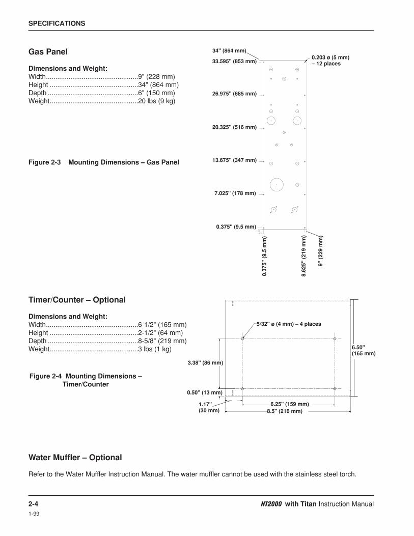
Gas Panel
Dimensions and Weight:Width.................................................9" (228 mm)Height ...............................................34" (864 mm)Depth ................................................6" (150 mm)Weight...............................................20 lbs (9 kg)
Figure 2-3 Mounting Dimensions – Gas Panel
0.203 ø (5 mm) – 12 places
Figure 2-4 Mounting Dimensions –Timer/Counter
6.50" (165 mm)
5/32" ø (4 mm) – 4 places
1.17" (30 mm)
0.50" (13 mm)
3.38" (86 mm)
6.25" (159 mm)8.5" (216 mm)
Water Muffler – Optional
Refer to the Water Muffler Instruction Manual. The water muffler cannot be used with the stainless steel torch.
Timer/Counter – Optional
Dimensions and Weight:Width.................................................6-1/2" (165 mm)Height ...............................................2-1/2" (64 mm)Depth ................................................8-5/8" (219 mm)Weight...............................................3 lbs (1 kg)

HT2000 with Titan Instruction Manual 3-1
Section 3
INSTALLATION
Gas or water Torque Specification
hose size lbf-in lbf-ft kgf-cm
up to 3/8" (10 mm) 75-85 6.25-7 86-98
1/2" (12 mm) 360-480 30-40 415-550
Pre-installation
See the HT2000 instruction manual 802070 Pre-installation section for system requirements.
System Units Placement
• Position all required units prior to making electrical, gas and interface connections.
• Ground all external modules in the HT2000 with Titan system to earth.
• To prevent leaks in the system, tighten all gas and water connections to the following specifications:
Use 2 wrenches when tightening to prevent damage to the mating component.
Use the diagram on the following 2 pages to make system interconnections. Follow the number guide on thediagram to find out specific information on each cable, hose or connection. The numbered items are detailed on thepages following the interconnection diagram.

Machine ComputerInterface
3-2 HT2000 with Titan Instruction Manual
To Water MufflerPump
Red
Green
Timer/Counter
HT2000 Power Supply Work Table
11X1
To SecondHT2000 Power Supply
12
11
9
8
10
2
5
1
3
7
6A
6B
4

HT2000 with Titan Instruction Manual 3-3
Gas HoseCoolant Hose
BlueGray GreenRed
Figure 3-1 HT2000 with Titan Interconnection Diagram
Abbreviations used in this section:HT2000 Power supply = PSRemote High Frequency and Motor Valve Console = RHF&MVHigh Frequency = HFVoltage, Current = V/CWater Muffler = WM
ShieldIN***
N2, Air, H35 PlasmaIN**
O2PlasmaIN*
Red
Green
RHF&MV Console – HF Panel
RHF&MV Console – Internal
HT2000 TitanRemote HighFrequency andMotor Valve(RHF&MV)Console
HT2000 TitanGas Panel
To TorchSee page 3-9.
Hardware connectionssupplied by customer.
* 1/4 NPT male adapter provided for plasma supply hose** 1/4 NPT female adapter provided for plasma supply hose*** 1/8 NPT male adapter provided for shield supply hose
5
13
7
1416
15
6A
6B
1
3
1
3
17
18
19
4

INSTALLATION
3-4 HT2000 with Titan Instruction Manual
Power Supply Connections
Note: All leads between the power supply and the RHF&MV console can be ordered as a package under onenumber – 128201.
Part No. Length
123041 60 ft (18.3 m)
Negative Lead – Power Supply (PS) to RHF&MV Console1 1
Part No. Length
123043 60 ft (18.3 m)
Pilot Arc lead – PS to RHF&MV Console3 3
Part No. Length
023755 4 ft (1.2 m)023920 8 ft (2.4 m)023508 10 ft (3 m)023403 15 ft (4.6 m)023404 25 ft (7.6 m)023968 30 ft (9.2 m)023986 35 ft (10.7 m)023405 50 ft (15 m)123041 60 ft (18.3 m)
Positive Lead – PS to Work Table2 2
Part No. Length
123042 60 ft (18.3 m)
RHF Cable – PS to RHF&MV Console4 4
1X1 2X1
From 1X1 To 2X1 Signal
34 1 RHF Door Intrlck35 4 RHF Door Intrlck36 3 Shield4 2 PS3 / Shield Gas8 5 PS3 / Shield Gas9 6 Cable Shield23 7 SV6 / Shield ON24 8 SV6 / Shield ON25 11 Shield
From 1X1 To 2X1 Signal
10 10 SV7 / Cap OFF11 13 SV7 / Cap OFF12 14 Shield1 12 T1 / HV Xfrmer2 15 T1 / HV Xfrmer3 16 Shield14 Unused15 Unused21 Shield

INSTALLATION
HT2000 with Titan Instruction Manual 3-5
Part No. Length
123292 60 ft (18.3 m)
MV Cable – PS to RHF&MV Console5 5
1X3 4X1
From 1X3 To 4X1 Signal
16 16 SV4A/ Cuflow17 17 SV4A/ Cutflow10 10 Shield23 23 SV4B/ Preflow24 24 SV4B/ Preflow25 25 Shield29 29 SV5 / Plasma OFF
From 1X3 To 4X1 Signal
30 30 SV5 / Plasma OFF34 34 Shield12 12 MV2 Decrease11 11 MV2 Decrease18 18 Shield14 14 MV2 Motor Increase21 21 Shield
Part No. Length
128052 60 ft (18.3 m)
Cooling Hoses – PS to RHF&MV Console6 6
This part number includes bothhoses.
6b
6a
RED
GRNGRN
RED
Part No. Length
023989 10 ft (3 m)023549 15 ft (4.6 m)023605 25 ft (7.6 m)023757 38 ft (11.6 m)023606 50 ft (15 m)123044 60 ft (18.3 m)023607 75 ft (23 m)123077 85 ft (25.9 m)023608 100 ft (30.5)023963 115 ft (35.1 m)123147 120 ft (36.6 m)023743 125 ft (38.1 m)023609 150 ft (46 m)023953 200 ft (62 m)
Gas Panel Cable – PS to Gas Panel7 7
1X2 3X1
From 1X2 To 3X1 Signal
29 29 S3 / MV2 Increase30 30 Spare34 34 Shield5 5 S3 / MV2 Decrease6 6 S3 / MV2 Common1 1 Shield2 2 LT1 / DC ON3 3 LT1 / DC ON7 7 Shield8 8 SV1A / O2 / N29 9 SV1A / O2 / N24 4 Shield16 16 SV2 / O2 / N217 17 SV2 / O2 / N210 10 Shield27 27 SV1B / O2 / N228 28 SV1B / O2 / N222 22 Shield
From 1X2 To 3X1 Signal
11 11 SV3 / Preflow Trap12 12 SV3 / Preflow Trap18 18 Shield19 19 S1 / N2 / O220 20 S1 / N2 / O213 13 Shield14 14 S2 / Test / Preflow15 15 S2 / Test / Common21 21 Shield35 35 S2 / Test / Operate36 36 S2 / Test / Common31 31 Shield32 32 PS1&PS233 33 PS1&PS237 37 Shield

INSTALLATION
3-6 HT2000 with Titan Instruction Manual
1X7
1X6
Machine V/C Interface Cable – PS to Machine Interface
From 1x6 Color Signal
2 Yellow Initial Height Sig. (OFF=Closed)6 Black Initial Height Com.11 Shield4 Orange Auto Height Sig. (OFF=Closed)8 Black Auto Height Com.13 Shield34 Red *†Lifter DOWN Load (DOWN=Closed)29 Black Lifter DOWN Line23 Shield35 Green *†Lifter UP Load (UP=Closed)30 Black Lifter UP Line24 Shield36 Red Upper Limit Switch ( OFF=Closed)31 Blue Upper Limit Switch25 Shield
From 1x6 Color Signal
33 Red Arc Voltage (1/50 Arc Voltage)28 Yellow Arc Voltage27 Shield9 Blue Plasma START (START=Closed)15 Black Plasma START14 Shield37 Red †Arc Transfer (TRANSFER=Closed)32 Green †Arc Transfer26 Shield1 White Hold Ignition Sig. (HOLD=Closed)5 Black Hold Ignition Com.10 Shield3 Brown Ramp Down Error7 Black Ramp Down Error12 Shield
From 1x7 Color Signal
2 White Current 103 Red Current 204 Green Current 405 Orange Current 806 Blue Current 1007 White/Black Current 20010 Shld Shield11 Blue/Black Current Common
From 1x7 Color Signal
16 Black/Red Voltage V517 White/Red Voltage V1018 Orange/Red Voltage V2019 Blue/Red Voltage V4020 Red/Green Voltage V8021 Orange/Green Voltage V10022 Black/White/Red Voltage V20023 White/Black/Red Voltage VCommon
Part No. Length
023841 6 ft (1.8 m)023842 15 ft (4.6 m)023843 25 ft (7.6 m)023844 35 ft (10.7 m)023845 50 ft (15 m)123047 60 ft (18.3 m)023846 75 ft (23 m)
Part No. Length
123080 85 ft (25.9 m)023847 100 ft (30.5)023962 115 ft (35.1 m)123148 120 ft (36.6 m)023848 125 ft (38.1 m)023849 150 ft (46 m)023850 200 ft (62 m)
8 8
9 9
* Signals are AC relays. DC relays are available as an option from Hypertherm by ordering kit: 128404
Machine I/O Interface Cable – PS to Machine Interface
Part No. Length
023902 6 ft (1.8 m)023851 15 ft (4.6 m)023852 25 ft (7.6 m)023853 35 ft (10.7 m)023854 50 ft (15 m)
Part No. Length
023855 75 ft (23 m)023856 100 ft (30.5)023903 125 ft (38.1 m)023857 150 ft (46 m)023858 200 ft (62 m)
WARNING
When installing or servicing the HT2000 Titan, AC or DC line voltages may be present on the UP,DOWN and TRANSFER signals even if the power supply line disconnect switch is OFF. Make certainthat all line disconnect switches relating to the HT2000 Titan system are OFF during installation andwhen servicing.

1X10
INSTALLATION
HT2000 with Titan Instruction Manual 3-71-99
Water Muffler Pump Cable – Power Supply to Water Muffler Pump
See water muffler instruction manual 802050 to connect cable to pumpmotor, and to make remaining water muffler connections. The water mufflercannot be used with the stainless steel torch.
1010 Part No. Length
023866 50 ft (15 m)023867 75 ft (23 m)023868 100 ft (30.5)
From 1X10 Color To WM Pump Contactor
2 Black Coil4 White AC Neut.3 Green Ground
11X1
Hold Cable – Power Supply 1 to Power Supply 2
Wire HT2000Color TB3 Function
Black 13 Hold SignalRed 14 Hold CommonShield 15 Hold Shield
Part No. Length
023340 15 ft (4.6 m)023341 25 ft (7.6 m)023342 50 ft (15 m)023343 100 ft (30.5)023344 150 ft (46 m)
12
Shield Gas Hose – Gas Panel to RHF&MV Console13
12
Timer/Counter Cable – Power Supply to Timer/Counter11
11 Part No. Length
023687 10 ft (3 m)023692 25 ft (7.6 m)023758 38 ft (11.6 m)023693 50 ft (15 m)123046 60 ft (18.3 m)023694 75 ft (23 m)123079 85 ft (25.9 m)023695 100 ft (30.5)023993 115 ft (35.1 m)123189 120 ft (36.6 m)023696 150 ft (46 m)023954 200 ft (62 m)
From To HT200011x1 TB3 Color Function
1 2 White Starts and Arc time (CON1 Closed)2 1 Black Starts and Arc time (CON1 Closed)3 3 Drain Drain15 5 Red Error Counter (Ramp Down Error)16 4 Black Error Counter (Ramp Down Error)12 6 Drain Drain
Gas Panel Connections
See page 3-3 for gas panel connection to power supply.Hoses from supply gases to gas panel provided by the customer.
Note: The following 20 ft length hoses can be ordered as a package withone number – 128202.
Part No. Length
024349 20 ft (6.1 m)
13
Note: Turn counterclockwise to tighten

INSTALLATION
3-8 HT2000 with Titan Instruction Manual
Part No. Length
024067 20 ft (6.1 m)
Shield Gas Sense Hose – Gas Panel to RHF&MV Console14 14
Part No. Length
024017 20 ft (6.1 m)
Plasma Preflow Gas Hose – Gas Panel to RHF&MV Console15 15
Part No. Length
024308 20 ft (6.1 m)
Plasma Cut Flow Gas Hose – Gas Panel to RHF&MV Console16 16
Note: Turn counterclockwise to tighten

INSTALLATION
HT2000 with Titan Instruction Manual 3-9
RHF&MV Console to Torch Connections
See pages 3-2 and 3-3 for RHF&MV console connections to the power supply and gas panel.
Routing the Torch Leads
Caution: Before routing the leads, make sure the torch is removed from the torch leads.
Route the torch leads from the RHF&MV console to the torch through a festoon or a power track.
Connecting the Torch Leads to the Torch
Note: The following torch leads, hose, cable and torch with off-valve assembly can be orderedwith one number – 128200.
See page 3-3 for torch lead connections to the RHF&MV Console.
See page 3-1 for torque specifications.
Leads HT2000 Torch – RHF&MV Console to Torch17
17
Part 1Pilot/ShieldGas (Blue)
Green
Red
Gray
Green
Red
Gray
Part 4
Part 3
Part 2
Shielded TorchLeads Part No. Part 1 Part 2 Part 3 Part 4 Length
028994 023326 024192 023013 023013 25 ft (7.6 m)
See Figure 3-2 to make connections to torch.
1. Remove the 12" off-valve hose from the off-valve subassembly (if connected). Note that the fitting is left-handthreaded and turns in a clockwise direction to remove.
2. Slide the torch sleeve over the RHF torch leads and out of the way.
3. With the red and green torch leads, use a 3/8" open-end wrench to hold the torch body fittings and a 1/2" open-end wrench to turn the torch lead fittings. Attach the leads to the red and green tubes of the torch main body.
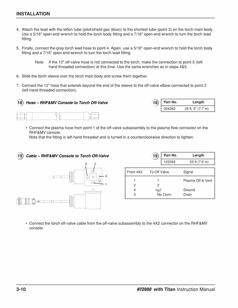
INSTALLATION
3-10 HT2000 with Titan Instruction Manual
4. Attach the lead with the teflon tube (pilot/shield gas (blue)) to the shortest tube (point 3) on the torch main body.Use a 5/16" open-end wrench to hold the torch body fitting and a 7/16" open-end wrench to turn the torch leadfitting.
5. Finally, connect the gray torch lead hose to point 4. Again, use a 5/16" open-end wrench to hold the torch bodyfitting and a 7/16" open-end wrench to turn the torch lead fitting.
Note: If the 12" off-valve hose is not connected to the torch, make the connection to point 5 (left-hand threaded connection) at this time. Use the same wrenches as in steps 4&5.
6. Slide the torch sleeve over the torch main body and screw them together.
7. Connect the 12" hose that extends beyond the end of the sleeve to the off-valve elbow connected to point 2(left-hand threaded connection).
Part No. Length
024283 25 ft, 5" (7.7 m)
Hose – RHF&MV Console to Torch Off-Valve18 18
• Connect the plasma hose from point 1 of the off-valve subassembly to the plasma flow connector on theRHF&MV console.Note that the fitting is left-hand threaded and is turned in a counterclockwise direction to tighten.
Part No. Length
123293 25 ft (7.6 m)
Cable – RHF&MV Console to Torch Off-Valve19 19
From 4X2 To Off Valve Signal
1 1 Plasma Off & Vent2 24 Ground3 No Conn. Drain
3
4
2
1
• Connect the torch off-valve cable from the off-valve subassembly to the 4X2 connector on the RHF&MVconsole.

INSTALLATION
HT2000 with Titan Instruction Manual 3-11
Figure 3-2 HT2000 Machine Torch Connections
Torch Off-Valve Cable
Plasma Hose
Off-valve subassembly
Point 2(left-handthreaded)
Off-valveconnector
Point 1(left-handthreaded)
Torchsleeve
12" Off-valve hose
Point 5(left-handthreaded)
Point 4
Red and Greentubes
Point 3
12" Off-valve hose
Torch main body
18
19

INSTALLATION
3-12 HT2000 with Titan Instruction Manual
Torch mounting bracket
90°0°
Securing screws
Figure 3-3 Torch Alignment
Torch sleeve
Torch Alignment
Prior to cutting with the machine torch, ensure that the torch is at right angles to the workpiece to get a clean,vertical cut. Use a square to align the torch. The torch should be aligned at 0° and 90°. See Figure 3-3.
Mounting the Machine Torch
1. Loosen the securing screw(s) and install the machine torch (with torch leads attached) in the torch mountingbracket. See Figure 3-3.
2. Position the torch until the torch body extends all the way through the bracket, so that the bracket is now aroundthe plastic torch sleeve and not touching the stainless steel torch body. Position the torch approximately 0.25" (6 mm) from the work surface.
3. Tighten the securing screws.

HT2000 with Titan Instruction Manual 4-1
Section 4
OPERATION
Refer to HT2000 Instruction manual 802070 for explanation of power supply and timer/counter front panel controlsand indicators.

OPERATION
4-2 HT2000 with Titan Instruction Manual
DesignationsFM1-FM2 –– FlowmeterLT1 –– Indicator LampMV2-MV4 –– Motor ValvePG1-PG3 –– Pressure GaugeS1-S3 –– Toggle Switch
N2 –– NitrogenO2 –– OxygenH35 –– Argon-Hydrogen
TestCut Flow
TestPreflow
Run
With Cut Gas Switch at N2/AIR/H35, Set Valve to Desired Gas.With Switch at O2, Set Valve to N2.
N2
H35 Air
AirCO2
N2 O2
O2N2 / Air / H35
O2N2AirH35
Cut FlowRateCut Gas
S2TEST PREFLOW – Sets the plasmapreflow flow rate on the flowmeter. Inthis position the contactor is disabled.TEST CUT FLOW – Allows the selectedplasma gas flow rate to be adjusted onthe flowmeter for cutting conditions. Inthis position the contactor is disabled.RUN – Enables the contactor and thesubsequent firing of the arc after the gasrates have been set in the Test Preflowand Test Cut Flow positions.
MV2Adjusts N2, air or H35 plasma gas flow rate % while in TEST PREFLOW mode.Preflow plasma gas flow rate percentagesare specified in the Cut Charts.
PG3Indicates shield gas pressure at the torch.
PLASMA SELECT SwitchSupplied by Messer
SHIELD SELECTPLASMA SELECT
MV4Adjusts shield gas pressure to the torch.
SHIELD SELECT SwitchSupplied by Messer
SHIELD GAS FLOW RATE
MV3Adjusts O2 plasma gas flow rate % whilein TEST PREFLOW mode. Preflowplasma gas flow rate percentages arespecified in the Cut Charts.
PREFLOWRATE ADJUST
S1Selects the use of either N2, air, H35 orO2 as the plasma cutting gas.
S3Adjusts N2, air or O2 plasma gas flow rate% while in TEST CUT FLOW mode.Plasma gas flow rate percentages arespecified in the Cut Charts.
PG2Indicates the O2 plasma inlet pressure.Gas inlet pressures are specified in theCut Charts.
PG1Indicates the N2, air or H35 plasma inletpressure. Gas inlet pressures arespecified in the Cut Charts
FM2Indicates the flow rate % of O2 plasmagas flow. Percentages are specified in theCut Charts.
FM1Indicates the flow rate % of N2, air orH35 plasma gas. Percentages arespecified in the Cut Charts.
LT1Illuminates when main contactor closes,indicating that DC power is beingsupplied to the torch
PLASMA GAS FLOW RATE
Figure 4-1 HT2000 Titan Gas Panel Controls and Indicators
Front Panel Controls and Indicators
HT2000 Titan Gas Panel (Fig. 4-1)

OPERATION
HT2000 with Titan Instruction Manual 4-3
Daily Start-up
Prior to start-up, ensure that your cutting environment and that your clothing meet the safety requirements outlinedin the Safety section of this manual. If problems occur during start-up, refer to Section 3 for installationrequirements.
Check Torch
1. Remove the consumables from the torch and check for worn or damaged parts. Always place theconsumables on a clean, dry, oil free surface after removing. Dirty consumables can cause the torch tomalfunction.
• Check the pit depth of the electrode using the electrode gauge assembly. A standard electrode should bereplaced when the depth exceeds .044 inch (1.1 mm). The SilverPlus electrode may be replaced when thepit depth exceeds approximately double the recommended depth of a standard electrode.
• Wipe the current ring in the torch with a clean paper towel or Q-tip. (See Fig. 4-2)
• Refer to the Cut Charts to choose the correct consumables for your cutting needs.
2. Replace consumable parts. Refer to Changing Consumable Parts later in this section for detailed information onreplacing consumables.
3. Ensure that the torch is squared to the material. Refer to Section 3: Installation for the torch alignmentprocedure.
Turn Gases On
4. Set S2 toggle switch on the gas panel to RUN.
5. Set S1 on the gas panel to N2/Air/H35 (for nitrogen, air or argon-hydrogen as plasma gas), or O2 (for oxygen as plasma gas).
6. Select the proper plasma and shield gases with the customersupplied interface. Note: When selecting O2 as the plasma gas, setPlasma Select switch to the N2 position.
7. Turn the required supply gases On.
• When using oxygen, nitrogen, or argon-hydrogen as theplasma gas, adjust supply regulator to read 120 psi +/- 10 psi(8.2 bar +/- 0.7 bar).
When using air as the plasma gas, adjust supply regulator toread 90 psi +/- 10 psi (6.2 bar +/- 0.7 bar).
• Adjust supply regulator for shield gas to read 90 psi +/- 10 psi(6.2 bar +/- 0.7 bar).
WARNING
Before operating this system, you must read the Safety section thoroughly! Turn main disconnectswitch to the HT2000 power supply OFF before proceeding with the following steps.
ShieldSelect
S1S2
PlasmaSelect

OPERATION
4-4 HT2000 with Titan Instruction Manual
Turn Power Supply On and Adjust Voltage/Current
8. Turn main disconnect switch ON.
9. Turn on the power supply by depressing the POWER ON (I) button (PB1) on the HT2000 power supply.Ensure that the green POWER ON indicator lights. If the POWER ON light fails to come on, see Section 3 forproper setup.
10. Set the voltage and current. Select the arc current and arc voltage from the Cut Charts for the type andthickness of metal to be cut.
Adjust Preflow Gases
11. Set S2 on the gas panel to TEST PREFLOW. Verify the plasmagas pressure reading on the plasma pressure gauges (PG1,PG2). Refer to the Cut Charts for the proper pressure setting.
12. Look at the oxygen (FM2) and/or nitrogen/air/argon-hydrogen(FM1) flowmeters on the gas panel and adjust the preflow plasmagas flow rate % by referring to the Cut Charts and turning theoxygen (MV3) and/or nitrogen/air/argon-hydrogen (MV2) preflowrate adjust metering valves.
13. Look at the shield gas pressure gauge (PG3) on the gas panel,and set to the Cut Chart specifications by turning the shield gasadjust metering valve (MV4).
Note: If the power supply has been off for more than 1 hour, or if you have changed consumable parts orhave changed gases, purge gas lines by leavingsystem in TEST PREFLOW for 1 minute.
Adjust Cut Flow Gases and Prepare for Cutting
14. Set S2 on the gas panel to TEST CUT FLOW.
15. Look at the oxygen (FM2) and/or nitrogen/air/argon-hydrogen(FM1) flowmeters on the gas panel and set the CUT FLOWplasma gas flow rate % by referring to the Cut Charts and togglingthe CUT FLOW RATE switch (S3) up or down.
Note: If the power supply has been off for more than 1 hour, or if you have changed consumable parts orhave changed gases, purge gas lines by leavingsystem in TEST PREFLOW for 1 minute.
16. Set S2 to RUN after the test preflow and test operate flow rateshave been set.
The system is now ready for operation.
PG1 PG2
MV2 MV3
PG3 MV4
FM1 FM2
S2
S2
S3
FM1 FM2

OPERATION
HT2000 with Titan Instruction Manual 4-5
Common Cutting Faults• Torch pilot arc will initiate, but will not transfer. Causes can be:
1. Work cable connection on cutting table not making good contact.2. Torch too far from workpiece (check Cut Chart information).
• The workpiece is not totally penetrated, and there is excessive sparking on top of the workpiece. Causescan be:1. Current is set too low (check Cut Chart information).2. Cut speed is too high (check Cut Chart information).3. Torch parts are worn (see Changing Consumable Parts).4. Metal being cut is too thick.
• Dross forms on the bottom of the cut. Causes can be:1. Cutting speed is too slow or too fast (check Cut Chart information).2. Arc current set too low (check Cut Chart information).3. Torch parts are worn (see Changing Consumable Parts).
• Cut angle not square. Causes can be:1. Wrong direction of machine travel. High quality side is on the right with respect to the forward motion of
the torch.2. Torch-to-work distance is not correct (check Cut Chart information).3. Cutting speed is not correct (check Cut Chart information).4. Arc current is not correct (check Cut Chart information).5. Damaged consumable parts (see Changing Consumable Parts ).
• Short consumable life. Causes can be:1. Arc current, arc voltage, travel speed, motion delay, gas flow rates, or initial torch height not set as
specified in Cut Charts.2. Attempting to cut highly magnetic metal plate (some metals such as armor plate with a high nickel
content) will shorten consumable life. Long consumable life is difficult to achieve when cutting plate thatis magnetized or becomes magnetized easily.
3. Not beginning or ending the cut on the plate surface. To achieve consumable long life, all cuts mustbegin and end on the plate surface.
Technical Questions
If your system does not function correctly:
1. Recheck all pre-installation and installation requirements and connections.2. If you are unable to solve the problem, call your distributor. He will be able to help you, or refer you to an
authorized Hypertherm repair facility.3. If you need assistance, call Hypertherm's Technical Service department listed in the front of this manual.
Cut Charts
The Cut Charts on the following pages provide the necessary information for the operator using the HT2000 Titansystem to be successful in plasma arc cutting. The HT2000 provides a wide travel speed operating window: usually± 10 ipm (± 254 mm/min) on most materials. The data listed in the charts are for making drop cuts with minimaldross.
Caution: Before cutting, check all settings and adjustments and check for damaged torchparts and worn consumable parts.
Conversions1 inch = 25.4 mm; 1 scfh = 28.316 liter/hour; 1 psi = .0689 bar = 6.895 KPa

OPERATION
4-6 HT2000 with Titan Instruction Manual2
CUT CHART AND CONSUMABLE PARTS INDEXPlasma Gas/ Retaining Swirl
Metal Amps Shield Gas Shield Cap Nozzle Ring Electrode Page
MildSteel
MildSteel
MildSteel
StainlessSteel
StainlessSteel
Aluminum
Aluminum
200 Air / Air 020424 120837 020608 020679 120667 4-7200 O2 / Air 020424 120837 020605 120833 120667 4-8200 N2 / CO2 020424 120837 020608 020607 020415 4-9100 Air / Air 020448 120837 020611 020607 120547 4-10100 O2 / Air 020424 120837 020690 020613 120547 4-1150 O2 / O2 120186 120185 120182 120179 120178 4-12
200 Air / Air 020424 120837 020608 020679 120667 4-13200 N2 / Air 020424 120837 020608 020607 020415 4-14200 N2 / CO2 020424 120837 020608 020607 020415 4-15200 H35 / N2* 020602 120837 020608 020607 020415 4-16100 Air / Air 020448 120837 020611 020607 120547 4-17100 H35 / N2* 020448 120837 020611 020607 020415 4-1840 Air / Air 020688 020423 020689 020613 120667 4-19
200 Air / Air 020424 120837 020608 020679 120667 4-20200 N2 / Air 020424 120837 020608 020607 020415 4-21200 N2 / CO2 020424 120837 020608 020607 020415 4-22200 H35 / N2* 020602 120837 020608 020607 020415 4-23100 Air / Air 020448 120837 020611 020607 120547 4-24100 H35 / N2* 020448 120837 020611 020607 020415 4-2540 Air / Air 020688 020423 020689 020613 120667 4-26
200 O2/Air 120260 120837 120259 120833 120258 4-27
200 Air / Air 020485 120837 020615 020607 120667 4-28
200 H35 / N2* 020485 120837 020615 020607 020415 4-28
200 H35 / N2* 020485 120837 020615 020607 020415 4-28
BEVELCUTTING
200 Air / Air 020566 120837 020608 020679 120667100 Air / Air 020618 120837 020611 020607 120547
200 O2 / Air 020566 120837 020605 120833 120667100 O2 / Air 020566 120837 020690 020613 120547
200 N2 / CO2 020566 120837 020608 020607 020415
200 N2 / Air 020566 120837 020608 020607 020415
Consumablesused withHT2000
Water Muffler*
** Do not use the water muffler when cutting with argon-hydrogen (H35)!
Note: If using the Command THC or other ohmic contact sensing device, use retaining caps with an IHS tab: 120837 clockwise;120838 counterclockwise for all cutting currents except 50A; 120185 for 50A cutting only.

OPERATION
HT2000 with Titan Instruction Manual 4-72
Shield Arc Approx.Material Plasma Gas Flow Rate % Gas (Air) Torch-to-work Initial Torch Voltage Motion
Thickness Preflow Cutflow Pressure Distance Piercing Height Setting Travel Speed Delay Time(inches) (mm) (Air %) (Air %) (psi) (inches) (mm) (inches) (mm) (volts) (ipm) (mm/min.) (sec)
Shield Arc Approx.Material Plasma Gas Flow Rate % Gas (Air) Torch-to-work Initial Torch Voltage Motion
Thickness Preflow Cutflow Pressure Distance Piercing Height Setting Travel Speed Delay Time(inches) (mm) (Air %) (Air %) (psi) (inches) (mm) (inches) (mm) (volts) (ipm) (mm/min.) (sec)
3/16 5 54 65 60 1/8 3 1/4 6 130 200 50801/4 6 (62.3 (75.0 (270 1/8 3 1/4 6 130 135 3400 0.5
.315 8 SCFH) SCFH) SCFH) 1/8 3 1/4 6 135 115 2900 0.53/8 10 1/8 3 1/4 6 135 100 2540 1.01/2 12 .157 4 .314 8 140 80 2030 2.05/8 15 .157 4 .314 8 145 60 1520 2.03/4 20 3/16 5 3/8 10 150 45 1140 2.57/8 22 1/4 6 1/2 12 155 30 760 2.5
1 25 1/4 6 1/2 12 160 25 635 2.51-1/4 32 1/4 6 165 15 3801-1/2 38 1/4 6 170 10 2501-3/4 44 5/16 8 180 7 180
2 50 5/16 8 185 5 130
Mild Steel200 amps • Air Plasma / Air Shield
This gas combination gives good cut speed, low dross levels and is very economical. Some surface nitriding canoccur.
Notes: Set plasma gas inlet pressure to 90 psi (6.2 bar)Set shield gas inlet pressure to 90 psi (6.2 bar)Production cutting above 1" (25 mm) not recommendedDrop cutting above 1-1/2" (38 mm) not recommended
Above Water
1/4 6 54 65 70 1/8 3 1/4 6 130 130 3300 0.5.315 8 (62.3 (75.0 (280 1/8 3 1/4 6 135 110 2700 0.53/8 10 SCFH) SCFH) SCFH) 1/8 3 1/4 6 135 95 2400 1.01/2 12 1/8 3 1/4 6 140 75 1900 2.05/8 15 .157 4 .314 8 145 50 1200 2.03/4 20 3/16 5 3/8 10 150 35 850 2.57/8 22 1/4 6 1/2 12 155 20 530 3.0
1 25 1/4 6 1/2 12 165 15 400 3.0
3" Under Water
020424Shield
120837Retaining cap
020608Nozzle
020679Swirl ring
120667Electrode

OPERATION
4-8 HT2000 with Titan Instruction Manual2
Shield Arc Approx.Material Plasma Gas Flow Rate % Gas (Air) Torch-to-work Initial Torch Voltage Motion
Thickness Preflow Cutflow Pressure Distance Piercing Height Setting Travel Speed Delay Time(inches) (mm) (O2 % N2 %) (O2 % N2 %) (psi) (inches) (mm) (inches) (mm) (volts) (ipm) (mm/min.) (sec)
Shield Arc Approx.Material Plasma Gas Flow Rate % Gas (Air) Torch-to-work Initial Torch Voltage Motion
Thickness Preflow Cutflow Pressure Distance Piercing Height Setting Travel Speed Delay Time(inches) (mm) (O2 % N2 %) (O2 % N2 %) (psi) (inches) (mm) (inches) (mm) (volts) (ipm) (mm/min.) (sec)
1/4 6 12 38 64 0 60 1/8 3 1/4 6 120 160 4060 0.5.315 8 (14.9 / 50.4 (79.6 / 0 (270 1/8 3 1/4 6 125 120 3000 0.53/8 10 SCFH) SCFH) SCFH) 1/8 3 1/4 6 125 100 2540 1.01/2 12 .157 4 .314 8 125 80 2030 2.05/8 15 .157 4 .314 8 130 70 1780 2.03/4 20 3/16 5 3/8 10 135 55 1400 2.57/8 22 1/4 6 1/2 12 135 45 1140 2.5
1 25 1/4 6 1/2 12 140 35 890 2.51 1/4 32 1/4 6 150 22 5601-1/2 38 1/4 6 155 15 3801-3/4 44 5/16 8 165 10 250
2 50 5/16 8 170 7 180
Mild Steel200 amps • O2 Plasma / Air Shield
This gas combination gives superior cut speed, minimum dross, minimum surface nitriding and excellentweldability.
Notes: Set oxygen plasma gas inlet pressure to 120 psi (8.3 bar). Set nitrogen plasma gas inlet pressure to 120 psi (8.3 bar)Set shield gas inlet pressure to 90 psi (6.2 bar)Production cutting above 1" (25 mm) not recommended. Drop cutting above 1-1/2" (38 mm) not recommended* Use 020679 swirl ring in place of 120833 swirl ring to obtain smoother cut edges on material
1/4" to 3/8" thick, but expect a 30-40% decrease in electrode life+ SilverPlus provides increased life to high duty cycle users in most applications. The hafnium wears to
approximately twice the depth of an all copper electrode (120667). Arc voltage may need to be increased by 5-10 volts throughout the electrode life to maintain proper cut height parameters.
Above Water
1/4 6 12 38 64 0 70 1/8 3 1/4 6 125 145 3700 0.5.315 8 (14.9 / 50.4 (79.6 / 0 (270 1/8 3 1/4 6 125 110 2800 0.53/8 10 SCFH) SCFH) SCFH) 1/8 3 1/4 6 130 80 2000 1.01/2 12 1/8 3 1/4 6 130 70 1800 2.05/8 15 .157 4 .314 8 135 60 1500 2.03/4 20 3/16 5 3/8 10 140 48 1200 2.57/8 22 1/4 6 1/2 12 140 38 950 3.0
1 25 1/4 6 1/2 12 145 25 680 3.0
3" Under Water
120833* (cw)120834 (ccw)Swirl ring
120667 (standard)Electrode 220084 (optional)SilverPlus electrode+
020605Nozzle
120837 (cw)120838 (ccw)Retaining cap
020424Shield

OPERATION
HT2000 with Titan Instruction Manual 4-92
Shield Arc Approx.Material Plasma Gas Flow Rate % Gas (CO2) Torch-to-work Initial Torch Voltage Motion
Thickness Preflow Cutflow Pressure Distance Piercing Height Setting Travel Speed Delay Time(inches) (mm) (N2 %) (N2 %) (psi) (inches) (mm) (inches) (mm) (volts) (ipm) (mm/min.) (sec)
3/16 5 50 60 60 1/8 3 1/4 6 120 130 3300 0.51/4 6 (62.3 (75.0 (270 1/8 3 1/4 6 125 110 2800 1.03/8 10 (SCFH) SCFH) SCFH) 1/8 3 1/4 6 130 85 2160 1.51/2 12 1/8 3 1/4 6 130 55 1400 2.05/8 15 .157 4 .314 8 135 45 1140 2.03/4 20 3/16 5 3/8 10 145 25 635 2.57/8 22 1/4 6 1/2 12 150 20 510 3.0
1 25 1/4 6 1/2 12 160 15 380 3.01-1/4 32 1/4 6 165 10 2501-1/2 38 1/4 6 175 5 130
Mild Steel200 amps • N2 Plasma / CO2 Shield
This gas combination may be used when cut edge quality and surface nitriding are less important. Electrode life isextended when using this combination.
Notes: Set plasma gas inlet pressure to 120 psi (8.3 bar)Set shield gas inlet pressure to 90 psi (6.2 bar)Production cutting above 1" (25 mm) not recommended
Above Water Only
020424Shield
120837Retaining cap
020608Nozzle
020607Swirl ring
020415Electrode

OPERATION
4-10 HT2000 with Titan Instruction Manual2
Shield Arc Approx.Material Plasma Gas Flow Rate % Gas (Air) Torch-to-work Initial Torch Voltage Motion
Thickness Preflow Cutflow Pressure Distance Piercing Height Setting Travel Speed Delay Time(inches) (mm) (Air %) (Air %) (psi) (inches) (mm) (inches) (mm) (volts) (ipm) (mm/min.) (sec)
Shield Arc Approx.Material Plasma Gas Flow Rate % Gas (Air) Torch-to-work Initial Torch Voltage Motion
Thickness Preflow Cutflow Pressure Distance Piercing Height Setting Travel Speed Delay Time(inches) (mm) (Air %) (Air %) (psi) (inches) (mm) (inches) (mm) (volts) (ipm) (mm/min.) (sec)
.075* 2 48 39 60 3/32 2.5 3/16 5 120 235 60501/8 3 (55.3 (44.9 (270 3/32 2.5 3/16 5 125 185 4700 0.5
3/16 5 SCFH) SCFH) SCFH) 1/8 3 1/4 6 125 175 4450 0.51/4 6 1/8 3 1/4 6 130 125 3175 0.53/8 10 1/8 3 1/4 6 135 50 1270 1.01/2 12 1/8 3 140 35 8905/8 15 .157 4 145 25 6353/4 20 3/16 5 150 20 510
Mild Steel100* amps • Air Plasma / Air Shield
This gas combination gives good cut speed, low dross levels and is very economical. Some surface nitriding canoccur. While this process may be used on thicker materials, optimal recommended range is to 3/8" (10mm).
* Set arc current to 80 amps when cutting .075" (2 mm) thick mild steel
Notes: Set plasma gas inlet pressure to 90 psi (6.2 bar)Set shield gas inlet pressure to 90 psi (6.2 bar)Production cutting above 3/8" (10 mm) not recommended
Above Water
1/8 3 48 39 70 5/64 2 5/32 4 130 120 30503/16 5 (55.3 (44.9 (270 1/8 3 1/4 6 135 90 2300 0.51/4 6 SCFH) SCFH) SCFH) 1/8 3 1/4 6 140 70 1730 0.53/8 10 1/8 3 1/4 6 145 42 1050 0.51/2 12 1/8 145 28 700
3" Under Water
020448Shield
120837Retaining cap
020611Nozzle
020607Swirl ring
120547Electrode
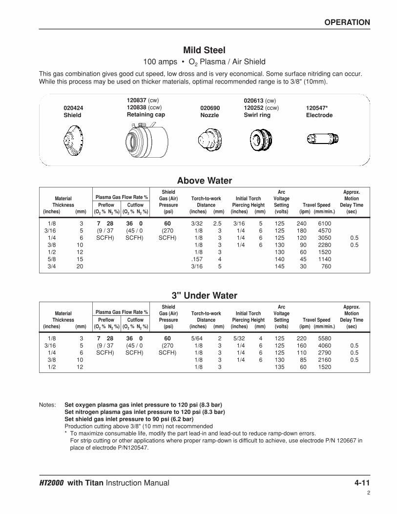
OPERATION
HT2000 with Titan Instruction Manual 4-112
Shield Arc Approx.Material Plasma Gas Flow Rate % Gas (Air) Torch-to-work Initial Torch Voltage Motion
Thickness Preflow Cutflow Pressure Distance Piercing Height Setting Travel Speed Delay Time(inches) (mm) (O2 % N2 %) (O2 % N2 %) (psi) (inches) (mm) (inches) (mm) (volts) (ipm) (mm/min.) (sec)
Shield Arc Approx.Material Plasma Gas Flow Rate % Gas (Air) Torch-to-work Initial Torch Voltage Motion
Thickness Preflow Cutflow Pressure Distance Piercing Height Setting Travel Speed Delay Time(inches) (mm) (O2 % N2 %) (O2 % N2 %) (psi) (inches) (mm) (inches) (mm) (volts) (ipm) (mm/min.) (sec)
1/8 3 7 28 36 0 60 3/32 2.5 3/16 5 125 240 61003/16 5 (9 / 37 (45 / 0 (270 1/8 3 1/4 6 125 180 45701/4 6 SCFH) SCFH) SCFH) 1/8 3 1/4 6 125 120 3050 0.53/8 10 1/8 3 1/4 6 130 90 2280 0.51/2 12 1/8 3 130 60 15205/8 15 .157 4 140 45 11403/4 20 3/16 5 145 30 760
Mild Steel100 amps • O2 Plasma / Air Shield
This gas combination gives good cut speed, low dross and is very economical. Some surface nitriding can occur.While this process may be used on thicker materials, optimal recommended range is to 3/8" (10mm).
Notes: Set oxygen plasma gas inlet pressure to 120 psi (8.3 bar)Set nitrogen plasma gas inlet pressure to 120 psi (8.3 bar)Set shield gas inlet pressure to 90 psi (6.2 bar)Production cutting above 3/8" (10 mm) not recommended* To maximize consumable life, modify the part lead-in and lead-out to reduce ramp-down errors.
For strip cutting or other applications where proper ramp-down is difficult to achieve, use electrode P/N 120667 inplace of electrode P/N120547.
Above Water
1/8 3 7 28 36 0 60 5/64 2 5/32 4 125 220 55803/16 5 (9 / 37 (45 / 0 (270 1/8 3 1/4 6 125 160 4060 0.51/4 6 SCFH) SCFH) SCFH) 1/8 3 1/4 6 125 110 2790 0.53/8 10 1/8 3 1/4 6 130 85 2160 0.51/2 12 1/8 3 135 60 1520
3" Under Water
020613 (cw)120252 (ccw)Swirl ring
120547*Electrode
020690Nozzle
120837 (cw)120838 (ccw)Retaining cap
020424Shield

OPERATION
4-12 HT2000 with Titan Instruction Manual
Shield Arc Approx.Material Plasma Gas Flow Rate % Gas (O2) Torch-to-work Initial Torch Voltage Motion
Thickness Preflow Cutflow Pressure Distance Piercing Height Setting Travel Speed Delay Time(inches) (mm) (O2 % N2 %) (O2 % N2 %) (psi) (inches) (mm) (inches) (mm) (volts) (ipm) (mm/min.) (sec)
.048 (18 GA.) 3 27 30 0 18 .060 1.50 .120 3.0 108 160 4060 0
.074 (14 GA.) 2 / 17 18 / 0 17 .060 1.50 .120 3.0 108 120 3050 0.3
.100 (12 GA.) l/min l/min l/min .070 1.75 .140 3.5 113 100 2540 0.3
.125 (10 GA.) .080 2.00 .160 4.0 118 60 1520 0.5
Mild Steel50 amps • O2 Plasma / O2 Shield
Notes: Set oxygen plasma gas inlet pressure to 120 psi (8.3 bar)Set nitrogen plasma gas inlet pressure to 120 psi (8.3 bar)Set shield gas inlet pressure to 120 psi (8.3 bar)The oxygen shield gas must be supplied from a regulator separate from the oxygen plasma gas regulator.If using the Digital Remote (DR) or Programmable Remote (PR), set current to 60 amps.If using a torch height control system capable of achieving the arc voltage setting on this chart, set accordingly.If using a less sensitive torch height control system, round off the arc voltage numbers to the nearest achievablesetting.Torch-to-work Distance tolerances are ± .010 inch (± .25 mm). When using a THC the tolerances are ± 1 volt.Stay within travel speed ranges to produce dross-free cuts.Due to the low gas flow rates associated with the 50 amp process, initial cut quality may be degraded while nitrogen isbeing purged from the gas line when changing from preflow to cut flow (up to 2 seconds). To compensate, eitherincrease machine motion delay or increase the lead-in distance at the start of the cut.Note that some height control systems may need to be locked out to prevent the torch from diving into the plate if themachine motion delay option is used.
Above Water Only
120185Retaining cap
120186Shield
120182Nozzle
120179Swirl ring
120178Electrode

OPERATION
HT2000 with Titan Instruction Manual 4-132
Shield Arc Approx.Material Plasma Gas Flow Rate % Gas (Air) Torch-to-work Initial Torch Voltage Motion
Thickness Preflow Cutflow Pressure Distance Piercing Height Setting Travel Speed Delay Time(inches) (mm) (Air %) (Air %) (psi) (inches) (mm) (inches) (mm) (volts) (ipm) (mm/min.) (sec)
Shield Arc Approx.Material Plasma Gas Flow Rate % Gas (Air) Torch-to-work Initial Torch Voltage Motion
Thickness Preflow Cutflow Pressure Distance Piercing Height Setting Travel Speed Delay Time(inches) (mm) (Air %) (Air %) (psi) (inches) (mm) (inches) (mm) (volts) (ipm) (mm/min.) (sec)
3/16 5 54 65 60 1/8 3 1/4 5 125 220 56001/4 6 (62.3 (75.0 (270 1/8 3 1/4 6 130 195 5000 0.53/8 10 SCFH) SCFH) SCFH) 1/8 3 1/4 6 130 145 3700 1.01/2 12 1/8 3 1/4 6 135 105 2700 2.05/8 15 .157 4 .314 8 140 75 1900 2.03/4 20 3/16 5 3/8 10 140 55 1400 2.57/8 22 1/4 6 1/2 12 145 40 1000 3.0
1 25 1/4 6 150 30 7601-1/4 32 ` 1/4 6 160 15 3801-1/2 38 1/4 6 170 10 250
Stainless Steel200 amps • Air Plasma / Air Shield
This gas combination gives good cut speed, low dross and is very economical. Some surface nitriding and surfaceoxidation of alloying elements can occur.
Notes: Set air plasma gas inlet pressure to 90 psi (6.2 bar)Set air shield gas inlet pressure to 90 psi (6.2 bar)Production cutting above 7/8" (22 mm) not recommended
Above Water
3/16 5 54 65 70 1/8 3 1/4 6 125 210 53201/4 6 (62.3 (75.0 (280 1/8 3 1/4 6 130 180 4500 0.53/8 10 SCFH) SCFH) SCFH) 1/8 3 1/4 6 135 125 3150 1.01/2 12 1/8 3 1/4 6 140 90 2300 2.05/8 15 .157 4 .314 8 145 60 1520 2.03/4 20 3/16 5 3/8 10 145 45 1150 2.57/8 22 1/4 6 1/2 12 150 30 750 3.0
1 25 1/4 6 155 22 570
3" Under Water
020424Shield
120837Retaining cap
020608Nozzle
020679Swirl ring
120667Electrode

OPERATION
4-14 HT2000 with Titan Instruction Manual2
Shield Arc Approx.Material Plasma Gas Flow Rate % Gas (Air) Torch-to-work Initial Torch Voltage Motion
Thickness Preflow Cutflow Pressure Distance Piercing Height Setting Travel Speed Delay Time(inches) (mm) (N2 %) (N2 %) (psi) (inches) (mm) (inches) (mm) (volts) (ipm) (mm/min.) (sec)
Shield Arc Approx.Material Plasma Gas Flow Rate % Gas (Air) Torch-to-work Initial Torch Voltage Motion
Thickness Preflow Cutflow Pressure Distance Piercing Height Setting Travel Speed Delay Time(inches) (mm) (N2 %) (N2 %) (psi) (inches) (mm) (inches) (mm) (volts) (ipm) (mm/min.) (sec)
3/16 5 50 60 60 1/8 3 1/4 5 125 135 34301/4 6 (66.4 (79.6 (270 1/8 3 1/4 6 130 120 3050 0.53/8 10 SCFH) SCFH) SCFH) 1/8 3 1/4 6 130 100 2540 1.01/2 12 1/8 3 1/4 6 135 75 1900 2.05/8 15 .157 4 .314 8 140 60 1520 2.03/4 20 3/16 5 3/8 10 140 45 1140 2.57/8 22 1/4 6 1/2 12 145 35 890 2.5
1 25 1/4 6 150 20 5101-1/4 32 ` 1/4 6 160 15 3801-1/2 38 1/4 6 160 10 250
Stainless Steel200 amps • N2 Plasma / Air Shield
This gas combination is used when cut edge quality, surface nitriding and surface oxidation of alloying elementsare less important. Electrode life is extended when this combination is used.
Notes: Set nitrogen plasma gas inlet pressure to 120 psi (8.3 bar)Set air shield gas inlet pressure to 90 psi (6.2 bar)Production cutting above 7/8" (22 mm) not recommended
Above Water
3/16 5 50 60 70 1/8 3 1/4 6 125 130 32501/4 6 (66.4 (79.6 (280 1/8 3 1/4 6 130 110 2750 0.53/8 10 SCFH) SCFH) SCFH) 1/8 3 1/4 6 135 85 2160 1.01/2 12 1/8 3 1/4 6 140 60 1520 2.05/8 15 .157 4 .314 8 145 45 1140 2.03/4 20 3/16 5 3/8 10 145 30 800 2.5
3" Under Water
020424Shield
120837Retaining cap
020608Nozzle
020607Swirl ring
020415Electrode

OPERATION
HT2000 with Titan Instruction Manual 4-152
Shield Arc Approx.Material Plasma Gas Flow Rate % Gas (CO2) Torch-to-work Initial Torch Voltage Motion
Thickness Preflow Cutflow Pressure Distance Piercing Height Setting Travel Speed Delay Time(inches) (mm) (N2 %) (N2 %) (psi) (inches) (mm) (inches) (mm) (volts) (ipm) (mm/min.) (sec)
Shield Arc Approx.Material Plasma Gas Flow Rate % Gas (CO2) Torch-to-work Initial Torch Voltage Motion
Thickness Preflow Cutflow Pressure Distance Piercing Height Setting Travel Speed Delay Time(inches) (mm) (N2 %) (N2 %) (psi) (inches) (mm) (inches) (mm) (volts) (ipm) (mm/min.) (sec)
3/16 5 50 60 60 1/8 3 1/4 6 125 190 4800 0.51/4 6 (66.4 (79.6 (210 1/8 3 1/4 6 130 170 4300 1.03/8 10 SCFH) SCFH) SCFH) 1/8 3 1/4 6 130 125 3200 1.51/2 12 1/8 3 1/4 6 135 95 2400 2.05/8 15 .157 4 .314 8 140 70 1800 2.03/4 20 3/16 5 3/8 10 140 50 1250 2.57/8 22 1/4 6 1/2 12 145 40 1000 3.0
1 25 1/4 6 150 30 7601-1/4 32 ` 1/4 6 160 15 3801-1/2 38 1/4 6 170 10 250
Stainless Steel200 amps • N2 Plasma / CO2 Shield
This gas combination is used when surface nitriding and surface oxidation of alloying elements is less important.Electrode life is extended when using this gas combination.
Notes: Set nitrogen plasma gas inlet pressure to 120 psi (8.3 bar)Set carbon dioxide shield gas inlet pressure to 90 psi (6.2 bar)Production cutting above 7/8" (22 mm) not recommended
Above Water
3/16 5 50 60 60 1/8 3 1/4 6 125 180 4550 0.51/4 6 (66.4 (79.6 (210 1/8 3 1/4 6 130 150 3850 1.03/8 10 SCFH) SCFH) SCFH) 1/8 3 1/4 6 135 110 2700 1.51/2 12 1/8 3 1/4 6 140 75 1920 2.05/8 15 .157 4 .314 8 145 50 1350 2.03/4 20 3/16 5 3/8 10 145 38 950 2.57/8 22 1/4 6 1/2 12 150 28 700 3.0
3" Under Water
020424Shield
120837Retaining cap
020608Nozzle
020607Swirl ring
020415Electrode

OPERATION
4-16 HT2000 with Titan Instruction Manual2
Shield Arc Approx.Material Plasma Gas Flow Rate % Gas (N2) Torch-to-work Initial Torch Voltage Motion
Thickness Preflow Cutflow Pressure Distance Piercing Height Setting Travel Speed Delay Time(inches) (mm) (H35 %) (H35 %) (psi) (inches) (mm) (inches) (mm) (volts) (ipm) (mm/min.) (sec)
1/4 6 25 25 60 3/16 5 3/8 10 135 62 1600 1.03/8 10 (89.9 (89.9 (275 3/16 5 3/8 10 140 52 1300 1.01/2 12 SCFH) SCFH) SCFH) 3/16 5 3/8 10 140 42 1100 2.05/8 15 S 1/4 6 1/2 12 145 37 940 2.03/4 20 1/4 6 1/2 12 150 32 810 2.57/8 22 5/16 8 5/8 16 155 27 690 2.5
1 25 5/16 8 155 22 5601-1/4 32 ` 5/16 8 165 16 4001-1/2 38 5/16 8 170 11 2801-3/4 44 5/16 8 180 8 200
2 50 5/16 8 185 6 150
Stainless Steel200 amps • H35 Plasma / N2 Shield
This gas combination (Hypertherm recommends a mixture of 35% hydrogen and 65% argon for the plasma gas)gives maximum thickness cutting capability, minimum dross levels, minimum amount of surface contamination,excellent weldability and excellent cut quality on thicknesses greater than 1/2". On thicknesses less than 1/2",excessive dross levels may be experienced. Electrode life is extended when this combination is used.
Notes: Set argon-hydrogen plasma gas inlet pressure to 120 psi (8.3 bar)Set nitrogen shield gas inlet pressure to 90 psi (6.2 bar)Drop cutting above 1-1/2" (38 mm) not recommended.Production cutting above 7/8" (22 mm) not recommended
Above Water Only
WARNING
Do not use water mufflerwhen cutting with argon-hydrogen
020602Shield
120837Retaining cap
020608Nozzle
020607Swirl ring
020415Electrode

OPERATION
HT2000 with Titan Instruction Manual 4-172
Shield Arc Approx.Material Plasma Gas Flow Rate % Gas (Air) Torch-to-work Initial Torch Voltage Motion
Thickness Preflow Cutflow Pressure Distance Piercing Height Setting Travel Speed Delay Time(inches) (mm) (Air %) (Air %) (psi) (inches) (mm) (inches) (mm) (volts) (ipm) (mm/min.) (sec)
Shield Arc Approx.Material Plasma Gas Flow Rate % Gas (Air) Torch-to-work Initial Torch Voltage Motion
Thickness Preflow Cutflow Pressure Distance Piercing Height Setting Travel Speed Delay Time(inches) (mm) (Air %) (Air %) (psi) (inches) (mm) (inches) (mm) (volts) (ipm) (mm/min.) (sec)
1/8 3 48 39 60 3/32 2.5 3/16 5 125 140 35603/16 5 (53.3 (44.9 (270 1/8 3 1/4 6 130 110 2800 0.51/4 6 SCFH) SCFH) SCFH) 1/8 3 1/4 6 130 80 2030 0.53/8 10 1/8 3 1/4 6 135 55 1400 0.51/2 12 1/8 3 140 35 8905/8 15 .157 4 145 25 6353/4 20 3/16 5 150 20 510
Stainless Steel100 amps • Air Plasma / Air Shield
This gas combination gives good cut speed, low dross and is very economical. Some surface nitriding and surfaceoxidation of alloying elements can occur.
Notes: Set air plasma gas inlet pressure to 90 psi (6.2 bar)Set air shield gas inlet pressure to 90 psi (6.2 bar)Production cutting above 3/8" (10 mm) not recommended
Above Water
1/8 3 48 39 60 5/64 2 5/32 4 125 135 34003/16 5 (53.3 (44.9 (270 1/8 3 1/4 6 130 100 2520 0.51/4 6 SCFH) SCFH) SCFH) 1/8 3 1/4 6 135 65 1720 0.53/8 10 1/8 3 1/4 6 140 45 1120 0.51/2 12 1/8 3 145 25 670
3" Under Water
020448Shield
120837Retaining cap
020611Nozzle
020607Swirl ring
120547Electrode

OPERATION
4-18 HT2000 with Titan Instruction Manual2
Shield Arc Approx.Material Plasma Gas Flow Rate % Gas (N2) Torch-to-work Initial Torch Voltage Motion
Thickness Preflow Cutflow Pressure Distance Piercing Height Setting Travel Speed Delay Time(inches) (mm) (H35 %) (H35 %) (psi) (inches) (mm) (inches) (mm) (volts) (ipm) (mm/min.) (sec)
1/8 3 13 13 60 3/32 2.5 3/16 5 130 50 12603/16 5 (46.7 (46.7 (270 1/8 3 1/4 6 135 40 1060 0.51/4 6 SCFH) SCFH) SCFH) 3/16 5 3/8 10 140 35 890 0.53/8 10 3/16 5 3/8 10 140 30 750 0.51/2 12 3/16 5 3/8 10 145 25 630 1.0
Stainless Steel100 amps • H35 Plasma / N2 Shield
This gas combination (Hypertherm recommends a mixture of 35% hydrogen and 65% argon for the plasma gas)gives good cut speed, but may result in excessive dross. Some surface nitriding and surface oxidation of alloyingelements can occur.
Notes: Set argon-hydrogen plasma gas inlet pressure to 120 psi (8.3 bar)Set nitrogen shield gas inlet pressure to 90 psi (6.2 bar)Production cutting above 3/8" (10 mm) not recommended
Above Water Only
020448Shield
120837Retaining cap
020611Nozzle
020607Swirl ring
020415Electrode
WARNING
Do not use water mufflerwhen cutting with argon-hydrogen

OPERATION
HT2000 with Titan Instruction Manual 4-192
Shield Arc Approx.Material Plasma Gas Flow Rate % Gas (Air) Torch-to-work Initial Torch Voltage Motion
Thickness Preflow Cutflow Pressure Distance Piercing Height Setting Travel Speed Delay Time(inches) (mm) (Air %) (Air %) (psi) (inches) (mm) (inches) (mm) (volts) (ipm) (mm/min.) (sec)
.050 (18 GA.) 40 20 60 3/32 2.5 3/16 5 120 145 37001/16 1.5 (46.0 (23.1 (275 3/32 2.5 3/16 5 120 120 30501/8 3 SCFH) SCFH) SCFH) 3/32 2.5 3/16 5 125 75 1900 0.51/4 6 1/8 3 135 24 6103/8 10 1/8 3 140 12 300
Stainless Steel40 amps • Air Plasma / Air Shield
This gas combination gives good cut speed, low dross level and is very economical. Some surface nitriding andsurface oxidation of alloying elements can occur.
Notes: Set air plasma gas inlet pressure to 90 psi (6.2 bar)Set air shield gas inlet pressure to 90 psi (6.2 bar)Production cutting above 1/8" (3 mm) not recommended
Above Water Only
020688Shield
020423Retaining cap
020689Nozzle
020613Swirl ring
120667Electrode

OPERATION
4-20 HT2000 with Titan Instruction Manual2
Shield Arc Approx.Material Plasma Gas Flow Rate % Gas (Air) Torch-to-work Initial Torch Voltage Motion
Thickness Preflow Cutflow Pressure Distance Piercing Height Setting Travel Speed Delay Time(inches) (mm) (Air %) (Air %) (psi) (inches) (mm) (inches) (mm) (volts) (ipm) (mm/min.) (sec)
Shield Arc Approx.Material Plasma Gas Flow Rate % Gas (Air) Torch-to-work Initial Torch Voltage Motion
Thickness Preflow Cutflow Pressure Distance Piercing Height Setting Travel Speed Delay Time(inches) (mm) (Air %) (Air %) (psi) (inches) (mm) (inches) (mm) (volts) (ipm) (mm/min.) (sec)
3/16 5 54 65 60 1/8 3 1/4 6 130 220 5600 0.51/4 6 (62.3 (75.0 (270 1/8 3 1/4 6 140 190 4800 1.03/8 10 SCFH) SCFH) SCFH) 1/8 3 1/4 6 140 145 3700 2.01/2 12 1/8 3 1/4 6 145 110 2800 2.55/8 15 .157 4 .314 8 150 85 2200 2.53/4 20 3/16 5 3/8 10 155 65 1650 2.57/8 22 1/4 6 1/2 12 160 50 1300 2.5
1 25 1/4 6 165 35 9001-1/4 32 ` 1/4 6 170 20 5001-1/2 38 1/4 6 175 12 300
Aluminum200 amps • Air Plasma / Air Shield
This gas combination gives good cut speed, low dross levels and is very economical.
Notes: Set plasma gas inlet pressure to 90 psi (6.2 bar)Set shield gas inlet pressure to 90 psi (6.2 bar)Production cutting above 7/8" (22 mm) not recommended
Above Water
3/16 5 54 65 70 1/8 3 1/4 6 135 210 5300 0.51/4 6 (62.3 (75.0 (280 1/8 3 1/4 6 140 170 4300 1.03/8 10 SCFH) SCFH) SCFH) 1/8 3 1/4 6 145 125 3150 2.01/2 12 1/8 3 1/4 6 150 90 2240 2.55/8 15 .157 4 .314 8 155 65 1650 3.03/4 20 3/16 5 3/8 10 160 45 1150 3.0
3" Under Water
020424Shield
120837Retaining cap
020608Nozzle
020679Swirl ring
120667Electrode

OPERATION
HT2000 with Titan Instruction Manual 4-212
Shield Arc Approx.Material Plasma Gas Flow Rate % Gas (Air) Torch-to-work Initial Torch Voltage Motion
Thickness Preflow Cutflow Pressure Distance Piercing Height Setting Travel Speed Delay Time(inches) (mm) (N2 %) (N2 %) (psi) (inches) (mm) (inches) (mm) (volts) (ipm) (mm/min.) (sec)
Shield Arc Approx.Material Plasma Gas Flow Rate % Gas (Air) Torch-to-work Initial Torch Voltage Motion
Thickness Preflow Cutflow Pressure Distance Piercing Height Setting Travel Speed Delay Time(inches) (mm) (N2 %) (N2 %) (psi) (inches) (mm) (inches) (mm) (volts) (ipm) (mm/min.) (sec)
3/16 5 50 60 60 1/8 3 1/4 6 130 180 4570 0.51/4 6 (66.4 (79.6 (270 1/8 3 1/4 6 135 160 4060 1.03/8 10 SCFH) SCFH) SCFH) 1/8 3 1/4 6 135 120 3050 1.51/2 12 1/8 3 1/4 6 140 80 2030 2.05/8 15 .157 4 .314 8 140 70 1780 2.03/4 20 3/16 5 3/8 10 150 50 1270 2.57/8 22 1/4 6 1/2 12 160 35 890 2.5
1 25 1/4 6 165 25 6351-1/4 32 ` 1/4 6 175 20 5101-1/2 38 1/4 6 185 10 250
Aluminum200 amps • N2 Plasma / Air Shield
This gas combination is used when cut edge quality is less important. Electrode life is extended when thiscombination is used.
Notes: Set plasma gas inlet pressure to 120 psi (8.3 bar)Set shield gas inlet pressure to 90 psi (6.2 bar)Production cutting above 7/8" (22 mm) not recommended
Above Water
3/16 5 50 60 70 1/8 3 1/4 6 135 170 4350 0.51/4 6 (66.4 (79.6 (280 1/8 3 1/4 6 140 140 3650 1.03/8 10 SCFH) SCFH) SCFH) 1/8 3 1/4 6 140 100 2600 1.51/2 12 1/8 3 1/4 6 145 65 1620 2.05/8 15 .157 4 .314 8 145 55 1350 2.53/4 20 3/16 5 3/8 10 155 35 890 3.07/8 22 1/4 6 1/2 12 165 25 620 3.0
3" Under Water
020424Shield
120837Retaining cap
020608Nozzle
020607Swirl ring
020415Electrode

OPERATION
4-22 HT2000 with Titan Instruction Manual2
Shield Arc Approx.Material Plasma Gas Flow Rate % Gas (CO2) Torch-to-work Initial Torch Voltage Motion
Thickness Preflow Cutflow Pressure Distance Piercing Height Setting Travel Speed Delay Time(inches) (mm) (N2 %) (N2 %) (psi) (inches) (mm) (inches) (mm) (volts) (ipm) (mm/min.) (sec)
Shield Arc Approx.Material Plasma Gas Flow Rate % Gas (CO2) Torch-to-work Initial Torch Voltage Motion
Thickness Preflow Cutflow Pressure Distance Piercing Height Setting Travel Speed Delay Time(inches) (mm) (N2 %) (N2 %) (psi) (inches) (mm) (inches) (mm) (volts) (ipm) (mm/min.) (sec)
3/16 5 50 60 60 1/8 3 1/4 6 130 185 4700 0.51/4 6 (66.4 (79.6 (210 1/8 3 1/4 6 135 160 4050 1.03/8 10 SCFH) SCFH) SCFH) 1/8 3 1/4 6 135 120 3050 2.01/2 12 1/8 3 1/4 6 140 95 2400 2.55/8 15 .157 4 .314 8 140 70 1800 2.53/4 20 3/16 5 3/8 10 150 55 1400 3.07/8 22 1/4 6 1/2 12 160 42 1050 3.0
1 25 1/4 6 165 33 8401-1/4 32 ` 1/4 6 175 20 5101-1/2 38 5/16 8 185 11 280
Aluminum200 amps • N2 Plasma / CO2 Shield
This gas combination is used when cut edge quality is less important. Electrode life is extended when thiscombination is used.
Notes: Set plasma gas inlet pressure to 120 psi (8.3 bar)Set shield gas inlet pressure to 90 psi (6.2 bar)Production cutting above 7/8" (22 mm) not recommended
Above Water
3/16 5 50 60 60 1/8 3 1/4 6 130 175 4450 0.51/4 6 (66.4 (79.6 (220 1/8 3 1/4 6 135 145 3650 1.03/8 10 SCFH) SCFH) SCFH) 1/8 3 1/4 6 140 100 2600 2.01/2 12 1/8 3 1/4 6 145 75 1820 2.55/8 15 .157 4 .314 8 145 55 1350 2.53/4 20 3/16 5 3/8 10 155 40 980 3.07/8 22 1/4 6 1/2 12 165 30 750 3.0
3" Under Water
020424Shield
120837Retaining cap
020608Nozzle
020607Swirl ring
020415Electrode

OPERATION
HT2000 with Titan Instruction Manual 4-232
Shield Arc Approx.Material Plasma Gas Flow Rate % Gas (N2) Torch-to-work Initial Torch Voltage Motion
Thickness Preflow Cutflow Pressure Distance Piercing Height Setting Travel Speed Delay Time(inches) (mm) (H35 %) (H35 %) (psi) (inches) (mm) (inches) (mm) (volts) (ipm) (mm/min.) (sec)
3/16 5 25 25 60 3/16 5 3/8 10 130 170 4300 0.51/4 6 (89.9 (89.9 (275 3/16 5 3/8 10 130 155 4000 1.03/8 10 SCFH) SCFH) SCFH) 1/4 6 1/2 12 135 120 3000 2.01/2 12 1/4 6 1/2 12 140 100 2550 2.05/8 15 1/4 6 1/2 12 145 80 2000 2.53/4 20 5/16 8 5/8 16 150 60 1500 2.57/8 22 5/16 8 5/8 16 155 50 1250 2.5
1 25 5/16 8 155 40 10001-1/4 32 ` 5/16 8 165 26 6601-1/2 38 5/16 8 170 18 4601-3/4 44 5/16 8 180 12 300
2 50 5/16 8 185 7 180
Aluminum200 amps • H35 Plasma / N2 Shield
This gas combination (Hypertherm recommends a mixture of 35% hydrogen and 65% argon for the plasma gas)gives maximum thickness cutting capability, excellent cut quality and excellent weldability. Electrode life isextended when this combination is used.
Notes: Set plasma gas inlet pressure to 120 psi (8.3 bar)Set shield gas inlet pressure to 90 psi (6.2 bar)Production cutting above 7/8" (22 mm) not recommended
Above Water Only
020602Shield
120837Retaining cap
020608Nozzle
020607Swirl ring
020415Electrode
WARNING
Do not use water mufflerwhen cutting with argon-hydrogen

OPERATION
4-24 HT2000 with Titan Instruction Manual2
Shield Arc Approx.Material Plasma Gas Flow Rate % Gas (Air) Torch-to-work Initial Torch Voltage Motion
Thickness Preflow Cutflow Pressure Distance Piercing Height Setting Travel Speed Delay Time(inches) (mm) (Air %) (Air %) (psi) (inches) (mm) (inches) (mm) (volts) (ipm) (mm/min.) (sec)
Shield Arc Approx.Material Plasma Gas Flow Rate % Gas (Air) Torch-to-work Initial Torch Voltage Motion
Thickness Preflow Cutflow Pressure Distance Piercing Height Setting Travel Speed Delay Time(inches) (mm) (Air %) (Air %) (psi) (inches) (mm) (inches) (mm) (volts) (ipm) (mm/min.) (sec)
1/8 3 48 39 60 3/32 2.5 3/16 5 135 110 28003/16 5 (55.3 (44.9 (270 1/8 3 1/4 6 140 90 2290 0.51/4 6 SCFH) SCFH) SCFH) 1/8 3 1/4 6 145 70 1780 0.53/8 10 1/8 3 1/4 6 145 50 1270 0.51/2 12 1/8 3 150 40 10105/8 15 .157 4 155 30 7603/4 20 3/16 5 160 25 635
Aluminum100 amps • Air Plasma / Air Shield
This gas combination gives good cut speed, low dross levels and is very economical.
Notes: Set plasma gas inlet pressure to 90 psi (6.2 bar)Set shield gas inlet pressure to 90 psi (6.2 bar)Production cutting above 3/8" (10 mm) not recommended
Above Water
1/8 3 48 39 70 5/64 2 5/32 4 135 100 26503/16 5 (55.3 (44.9 (280 1/8 3 1/4 6 140 80 2050 0.51/4 6 SCFH) SCFH) SCFH) 1/8 3 1/4 6 145 60 1510 0.53/8 10 1/8 3 1/4 6 150 40 1000 0.51/2 12 1/8 3 155 30 750
3" Under Water
020448Shield
120837Retaining cap
020611Nozzle
020607Swirl ring
120547Electrode
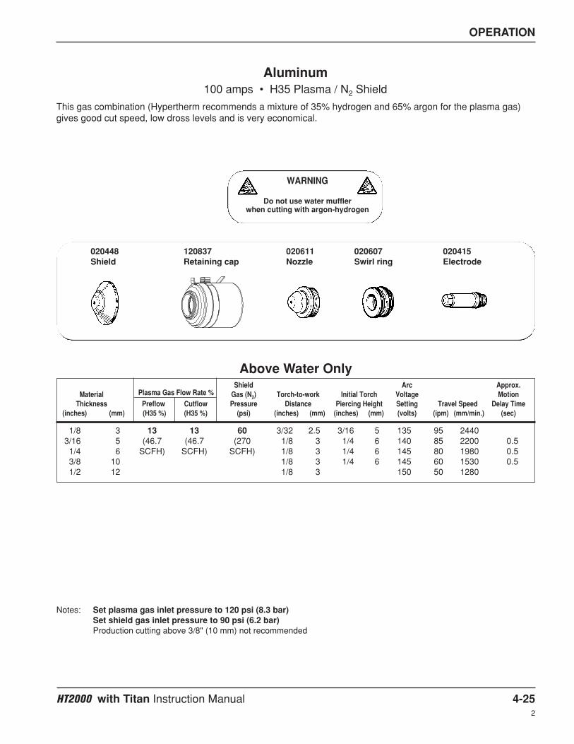
OPERATION
HT2000 with Titan Instruction Manual 4-252
Shield Arc Approx.Material Plasma Gas Flow Rate % Gas (N2) Torch-to-work Initial Torch Voltage Motion
Thickness Preflow Cutflow Pressure Distance Piercing Height Setting Travel Speed Delay Time(inches) (mm) (H35 %) (H35 %) (psi) (inches) (mm) (inches) (mm) (volts) (ipm) (mm/min.) (sec)
1/8 3 13 13 60 3/32 2.5 3/16 5 135 95 24403/16 5 (46.7 (46.7 (270 1/8 3 1/4 6 140 85 2200 0.51/4 6 SCFH) SCFH) SCFH) 1/8 3 1/4 6 145 80 1980 0.53/8 10 1/8 3 1/4 6 145 60 1530 0.51/2 12 1/8 3 150 50 1280
Aluminum100 amps • H35 Plasma / N2 Shield
This gas combination (Hypertherm recommends a mixture of 35% hydrogen and 65% argon for the plasma gas)gives good cut speed, low dross levels and is very economical.
Notes: Set plasma gas inlet pressure to 120 psi (8.3 bar)Set shield gas inlet pressure to 90 psi (6.2 bar)Production cutting above 3/8" (10 mm) not recommended
Above Water Only
020448Shield
120837Retaining cap
020611Nozzle
020607Swirl ring
020415Electrode
WARNING
Do not use water mufflerwhen cutting with argon-hydrogen

OPERATION
4-26 HT2000 with Titan Instruction Manual2
Shield Arc Approx.Material Plasma Gas Flow Rate % Gas (Air) Torch-to-work Initial Torch Voltage Motion
Thickness Preflow Cutflow Pressure Distance Piercing Height Setting Travel Speed Delay Time(inches) (mm) (Air %) (Air %) (psi) (inches) (mm) (inches) (mm) (volts) (ipm) (mm/min.) (sec)
3/32 2.5 40 20 60 3/32 2.5 3/16 5 120 140 35501/8 3 (46.0 (23.1 (275 3/32 2.5 3/16 5 130 100 2550 0.51/4 6 SCFH) SCFH) SCFH) 1/8 3 140 35 9003/8 10 1/8 3 150 15 350
Aluminum40 amps • Air Plasma / Air Shield
This gas combination gives good cut speed, low dross levels and is very economical.
Notes: Set plasma gas inlet pressure to 90 psi (6.2 bar)Set shield gas inlet pressure to 90 psi (6.2 bar)Production cutting above 1/8" (3 mm) not recommended
Above Water Only
020613Swirl ring
120667Electrode
020689Nozzle
020423Retaining cap
020688Shield
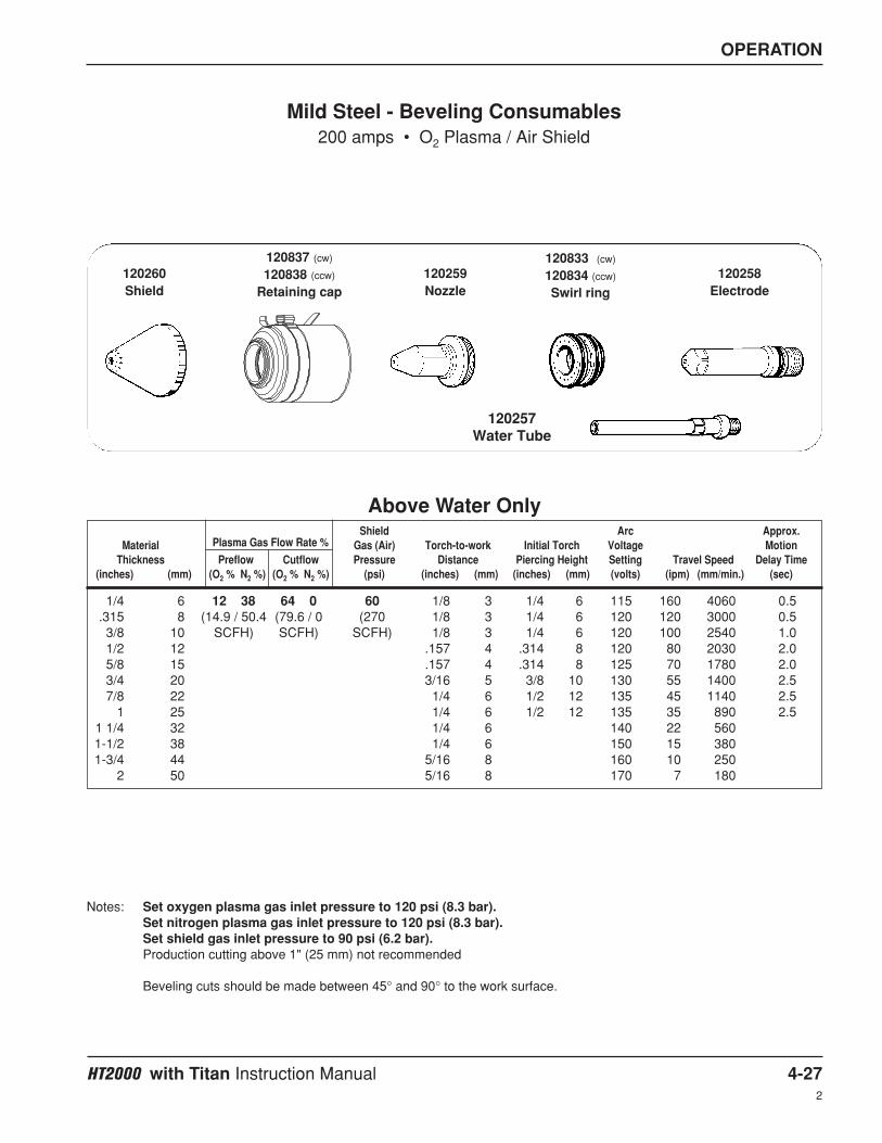
OPERATION
HT2000 with Titan Instruction Manual 4-272
Shield Arc Approx.Material Plasma Gas Flow Rate % Gas (Air) Torch-to-work Initial Torch Voltage Motion
Thickness Preflow Cutflow Pressure Distance Piercing Height Setting Travel Speed Delay Time(inches) (mm) (O2 % N2 %) (O2 % N2 %) (psi) (inches) (mm) (inches) (mm) (volts) (ipm) (mm/min.) (sec)
1/4 6 12 38 64 0 60 1/8 3 1/4 6 115 160 4060 0.5.315 8 (14.9 / 50.4 (79.6 / 0 (270 1/8 3 1/4 6 120 120 3000 0.53/8 10 SCFH) SCFH) SCFH) 1/8 3 1/4 6 120 100 2540 1.01/2 12 .157 4 .314 8 120 80 2030 2.05/8 15 .157 4 .314 8 125 70 1780 2.03/4 20 3/16 5 3/8 10 130 55 1400 2.57/8 22 1/4 6 1/2 12 135 45 1140 2.5
1 25 1/4 6 1/2 12 135 35 890 2.51 1/4 32 1/4 6 140 22 5601-1/2 38 1/4 6 150 15 3801-3/4 44 5/16 8 160 10 250
2 50 5/16 8 170 7 180
Mild Steel - Beveling Consumables200 amps • O2 Plasma / Air Shield
Notes: Set oxygen plasma gas inlet pressure to 120 psi (8.3 bar).Set nitrogen plasma gas inlet pressure to 120 psi (8.3 bar).Set shield gas inlet pressure to 90 psi (6.2 bar).Production cutting above 1" (25 mm) not recommended
Beveling cuts should be made between 45° and 90° to the work surface.
Above Water Only
120833 (cw)
120834 (ccw)
Swirl ring
120258Electrode
120257Water Tube
120259Nozzle
120837 (cw)
120838 (ccw)
Retaining cap120260Shield

OPERATION
4-28 HT2000 with Titan Instruction Manual2
Shield Arc Plasma Gas Shield GasPlasma Gas Flow Rate %
Gas (N2) Current (H35) Inlet (N2) InletPreflow Cut Flow Pressure Setting Pressure Pressure(H35 %) (H35 %) (psi) (amps) (psi) (psi)
Shield Arc Plasma Gas Shield GasPlasma Gas Flow Rate %
Gas (Air) Current (Air) Inlet (Air) InletPreflow Cut Flow Pressure Setting Pressure Pressure(Air %) (Air %) (psi) (amps) (psi) (psi)
71 71 50 200 90 90
(81.8 SCFH)
Mild Steel Gouging200 amps • Air Plasma / Air Shield
29 29 50 200 120 90
(81.8 SCFH)
Stainless Steel or Aluminum Gouging200 amps • H35 Plasma / N2 Shield
Hypertherm recommends a mixture of 35% hydrogen and 65% argon for the plasma gas.
020607Swirl ring
120667Electrode
020615Nozzle
120837Retaining cap
020485Shield
020607Swirl ring
020415Electrode
020615Nozzle
120837Retaining cap
020485Shield

OPERATION
HT2000 with Titan Instruction Manual 4-29
Changing Consumable Parts
Check the consumable parts daily for wear before cutting. Before removing parts, bring the torch to the edge of themachine, with the lifter raised to its highest point. This prevents the danger of dropping the consumables into thewater of the water table.
Removal and Inspection – Refer to Figure 4-2
1. Remove the retaining cap and shield by unscrewing the retaining cap by hand.
2. Check the shield for external signs of wear. It should be clean and clear of metal debris. The gas holes alongthe edge of the shield should not be blocked with debris. The center hole should not have any nicks or gouges,and should show no signs of arcing activity.
3. Unscrew and remove the shield from the retaining cap. Inspect the gas holes from the inside. The holes shouldbe clear of metal or other debris. (Debris can cause arcing.)
4. Inspect the two O-rings on the torch body. They should be lubricated and undamaged. If they are dry, lubricatethem lightly with a very thin film of the lubricant provided in the spare parts kit. If they are damaged, replacethem.
5. Using the 3/4" side of the wrench supplied with the consumable parts kit, remove the nozzle. Inspect it fordamage or signs of wear. You can clean the inside of the nozzle with steel wool, but be sure to remove anyremnants of the steel wool afterward. The hole in the nozzle should not be worn or oval-shaped.
6. Using the 3/8" center hole in the wrench, remove the electrode and inspect it. If the center of the electrode has apit more than .044" (1.1 mm) deep, replace it. Use the electrode gauge assembly supplied in the spare parts kitto measure pit depth. If the electrode is still good, inspect its O-ring: it should be lubricated and undamaged. If itis dry, lubricate it lightly with a very thin film of the lubricant provided in the spare parts kit. If it is damaged,replace it.
7. Remove the swirl ring from the electrode and inspect it. It should be clean, and the holes on the top and sidesshould not be plugged. Inspect its O-ring. It should be lubricated and undamaged. If it is dry, lubricate it lightlywith a very thin film of the lubricant provided in the spare parts kit. If it is damaged, replace it.
8. Inspect the inside of the torch body by using a mirror, or by looking carefully inside. The current ring inside ofthe torch body should be clean and undamaged. Use a clean paper towel or Q-tip to remove dirt, grease, etc. Apreferred method to clean the current ring is with a clean paper towel or Q-tip dipped in water or 3% hydrogenperoxide. If the water tube is damaged at all, it may need to be replaced. See Changing the Water Tube .
WARNING
Always disconnect power to the power supply before inspecting or changing torch consumableparts.

OPERATION
4-30 HT2000 with Titan Instruction Manual2
Replacement
1. Before installing the electrode, be sure to lightly grease the O-ring with a small amount of silicon lubricant.Replace the electrode and tighten it with the wrench. Do not overtighten.
2. Before installing the swirl ring, be certain that the O-rings have been lubricated with a small amount of silicongrease. Install the swirl ring with the bottom O-ring facing the inside of the torch. Push it into place. Be sure tohold the swirl ring in place until the nozzle is installed to avoid dropping it into the water of the water table.
3. Install the nozzle and finger-tighten it. Finish tightening it with the wrench. Do not overtighten.
4. Screw on the shield to the retaining cap and tighten by hand. Screw on the retaining cap to the torch by hand.Make sure that it is tightened snugly; if it is loose, it can affect the shield gas flow.
Figure 4-2 Changing Consumable Parts
Shield Retaining cap Nozzle Swirl ring Electrode
Currentring Torch body (shown without off valve SA and sleeve)
Water tube

OPERATION
HT2000 with Titan Instruction Manual 4-31
Changing the Water Tube
Problems and causes you may find with a defective or improperly installed water tube:
• Short electrode life: Water tube not screwed in tightly
• Flow switch interlock shutting down the system: Water flow restricted due to loose water tube.
• Humming or rattling sound coming from the torch: Water tube bent or loose
If you suspect a problem with the water tube, you may need to replace it.
1. Disconnect power supply from power source.
2. Remove all consumables from torch (see Changing Consumable Parts ).
3. Look for any damage or bends in the water tube.
4. Remove and replace the water tube by using the water tube wrench (027347) supplied by Hypertherm – Fig. 4-3. When installing water tube, do not over tighten! Snug down by hand only.
Figure 4-3 Changing the Water Tube
WARNING
Always disconnect the power supplyfrom the main power source before
inspecting or changing the torch parts.

OPERATION
4-32 HT2000 with Titan Instruction Manual

HT2000 with Titan Instruction Manual 5-1
Section 5
PARTS LIST
This section provides part numbers for the components in the HT2000 Titan Gas Panel, Remote HighFrequency&Motor Valve Console (also called “High Frequency Console”), and the HT2000 machine torch andconsumables for the Titan Integrated Plasma System.
• See Installation in this manual for cable and hose part numbers.
• See HT2000 Instruction manual 802070 for power supply information.

PARTS LIST
5-2 HT2000 with Titan Instruction Manual
23, 24
15
Figure 5-1 HT2000 Titan Gas Panel
19
21
20
18
1716
14
13
16
22
20
18
3
12
11
109
8
76
34, 52
1

PARTS LIST
HT2000 with Titan Instruction Manual 5-34-99
Gas Panel – 073220
PartItem Number Description Designator Qty.
1 001623 Panel:HT2000 Titan Gas Panel 12 011053 Flowmeter:0-10 SC/BP-8 Float Cal. 2% FM1 1
011058 Flowtube/BP-8 Float:0-10 SC Cal. 2%011008 Shield:Flowmeter Plastic011081 Flowmeter Float Stop
3 011053 Flowmeter:0-10 SC/BP-8 Float Cal. 2% FM2 1011058 Flowtube/BP-8 Float:0-10 SC Cal. 2%011008 Shield:Flowmeter Plastic011081 Flowmeter Float Stop
4 005149 Light bulb:120VAC LT1 15 005089 Lens:White 16 022027 Pressure Gauge:160# 1.5" PG1 17 022027 Pressure Gauge:160# 1.5" PG2 18 005180 Toggle Switch:SP3T ON/OFF/ON S2 19 005181 Toggle Switch:DPDT ON/NONE/ON S1 110 005042 Toggle Switch:SP Momentary ON/OFF/ON S3 111 004117 Cap:Needle Valve 312 022008 Pressure Gauge:100#/BAR 2.5" PG3 113 006109 Solenoid Valve:1/8FPT120V2W NC Manifold SV1B 114 006109 Solenoid Valve:1/8FPT120V2W NC Manifold SV1A 115 004718 Manifold:Motor Valve 116 005243 Pressure Switch:80 Psi 1/8 NPT PS2 117 005243 Pressure Switch:80 Psi 1/8 NPT PS1 118 006064 Meter Valve:1/8 FPT .125 Orifice MV3 119 006064 Meter Valve:1/8 FPT .125 Orifice MV2 120 006106 Solenoid Valve:1/8FPT 120V TFE Plunger SV3 121 006106 Solenoid Valve:1/8FPT 120V TFE Plunger SV2 122 006064 Meter Valve:1/8 FPT .125 Orifice MV4 1
129173 Harness:HT2000 Titan Gas Panel23 008176 Pin:24-20 AWG Type III 2124 008447 Receptacle Shell:CPC 23-37 Standard Sex 3X1 1

PARTS LIST
5-4 HT2000 with Titan Instruction Manual
23
22
21
24
20
19
18
17 1415 16
12 11
101113
8
9
7
5
64 32
1
Figure 5-2 HT2000 Titan RHF&MV Console

PARTS LIST
HT2000 with Titan Instruction Manual 5-51-00
RHF&MV Console – 073223
PartItem Number Description Designator Qty.
1 002279 Box:HT2000 Titan RHF 12 073221 High Frequency Panel Assembly 13 001626 Panel:HT2000 Titan RHF HF 14 005227 Pressure Switch:12 Psi PS3 15 006032 Solenoid Valve:150# 1/4 FPT 120V NC SV6 16 006106 Solenoid Valve:1/8FPT 120V SV7 17 006063 Motor-Valve:Electric 1/8FPT .125 Orifice MV1 18 006109 Solenoid Valve:1/8FPT120V2W NC SV4A 19 006109 Solenoid Valve:1/8FPT120V2W NC SV4B 110 029317 High Voltage Transformer SA:200/2000 T1 111 129188 HF/I0 PCB SA:HT2000 Titan RHF 112 001624 Bracket:HT2000 Titan RHF 113 004314 Block:200 Cathode 114 009350 Spark Gap Assembly:40-200/2000/HD SG1 115 004061 Electrode:Spark Gap 1/8 X 1.6 316 004140 Base:40/0/100/200/HD Spark Gap 117 004144 Bar:009350 Spark Gap Cap Mounting 118 009280 Cap:.002UF 15KV C3,C4 219 109074 Coil Assembly:HT2000 Titan High Freq. T2 120 041312 PCB Assembly:2000 I/O 121 129189 Panel SA:HT2000 Titan RHF 122 001625 Panel:HT2000 Titan RHF Side 123 129192 Harness:HT2000 Titan RHF 4X1,4X2,2X1 124 005100 Switch:Door Interlock S1 1

PARTS LIST
5-6 HT2000 with Titan Instruction Manual1-99
14 (Only used with the128383 torch)
13
3b
2
3a
3
5
6
4
1
10
10 12
7
11
9
8
Figure 5-3 HT2000 Torch Assembly with Valve, 25' (7.6 m) Leads and 2" (50 mm) Diameter Sleeve

PARTS LIST
HT2000 with Titan Instruction Manual 5-72
HT2000 Standard Machine Torch Assembly with Valve, 2" (50 mm) Dia. TorchSleeve, and 25' (7.6 m) Leads – 128383
PartItem Number Description Designator Qty.
128383 HT2000 Standard Torch Assy w/Valve and 25' Leads1 120837 Nozzle Retaining Cap, with IHS tab 12 020424 Shield, MAX200/HT2000 200A 13 120584 HT2000 Torch Main Body 13a 020963 Water Tube:PAC200T/2000 Electd Cool 13b 044027 O-Ring:Buna 70Duro 1.301X.070 24 020605 Nozzle, MAX200 200A .082 O2 15 120667 Electrode: HT2000 200A O2, LL 16 120833 Swirl Ring: HT2000 O2 1
129470 Off-Valve SA: HT2000 Mch Tch 17 006100 Solenoid Valve:150# 1/8 FPT SV5 18 020041 Tch Mtg Sleeve:2" 19 120832 Bracket:2" Dia Torch Off-Valve II 110 024355 Hose Assy:3/16Blu LH'A' 1' 1 ft11 123293 Cable, Torch Off-Valve 4X2 112 024283 Hose SA, 3/16 Blu LH 'A' 113 028994 Leads:HT2000 Torch Power with sleeve 25' 114 020407 Adapter:1-3/4"-2" Torch Mounting Sleeve 1
HT2000 Stainless Steel Machine Torch Assembly with Valve, 2" (50 mm) Dia.Torch sleeve, and 25' (7.6 m) Leads – 128368
PartItem Number Description Designator Qty.
128368 HT2000 Stainless Steel Torch Assy w/Valve and 25' Leads1 120837 Nozzle Retaining Cap, with IHS tab 12 020424 Shield, MAX200/HT2000 200A 13 120356 HT2000 SS Torch Main Body 13a 020963 Water Tube:PAC200T/2000 Electd Cool 13b 044027 O-Ring:Buna 70Duro 1.301X.070 24 020605 Nozzle, MAX200 200A .082 O2 15 120667 Electrode: HT2000 200A O2, LL 16 120833 Swirl Ring: HT2000 O2 1
129470 Off-Valve SA: HT2000 Mch Tch 17 006100 Solenoid Valve:150# 1/8 FPT SV5 18 020041 Tch Mtg Sleeve:2" 19 120832 Bracket:2" Dia Torch Off-Valve II 110 024355 Hose Assy:3/16Blu LH'A' 1' 1 ft11 123293 Cable, Torch Off-Valve 4X2 112 024283 Hose SA, 3/16 Blu LH 'A' 113 028994 Leads:HT2000 Torch Power with sleeve 25' 1
Torch Mounting Bracket for 2" (50 mm) Dia. sleeve – 020046

PARTS LIST
5-8 HT2000 with Titan Instruction Manual1-99
13
3b
2
3a
3
5
6
4
1
10
10 12
7
11
9
8
Figure 5-4 HT2000 Torch Assembly with Valve, 25' (7.6 m) Leads and 1-3/4" (44 mm) Diameter Sleeve

PARTS LIST
HT2000 with Titan Instruction Manual 5-92
HT2000 Optional Machine Torch Assembly with Valve, 1-3/4" (44 mm) Dia.Torch sleeve, and 25' (7.6 m) Leads – 128200
PartItem Number Description Designator Qty.
128200 HT2000 Optional Machine Torch Assy w/Valve and 25' Leads1 120837 Nozzle Retaining Cap, with IHS tab 12 020424 Shield, MAX200/HT2000 200A 13 120584 HT2000 Torch Main Body 13a 020963 Water Tube:PAC200T/2000 Electd Cool 13b 044027 O-Ring:Buna 70Duro 1.301X.070 24 020605 Nozzle, MAX200 200A .082 O2 15 120667 Electrode: HT2000 200A O2, LL 16 120833 Swirl Ring: HT2000 O2 1
129168 Off-Valve SA: HT2000 Mch Tch 17 006100 Solenoid Valve:150# 1/8 FPT SV5 18 020431 Tch Mtg Sleeve:1-3/4" GNRC 19 120492 Bracket:1-3/4" Dia Torch Off-Valve II 110 024355 Hose Assy:3/16Blu LH'A' 1' 1 ft11 123293 Cable, Torch Off-Valve 4X2 112 024283 Hose SA, 3/16 Blu LH 'A' 113 028994 Leads:HT2000 Torch Power with sleeve 25' 1
Torch Mounting Bracket for 1-3/4" (44 mm) Dia. sleeve – 020522

PARTS LIST
5-10 HT2000 with Titan Instruction Manual2
Figure 5-5 Consumable Parts
7
4
3 5
6
8
1 2
Consumable Parts Kit – 028602
PartItem Number Description Qty.
028602 Kit: HT2000 Spare Parts001067 Box: Gray Plastic 1
1 020424 Shield, 200A 11 020448 Shield, 100A 12 120837 Nozzle Retaining Cap, with IHS tab 13 020605 Nozzle, 200A .082 O2 53 020690 Nozzle, 100A .055 O2 34 020608 Nozzle, 200A .086 Air/N2/H35 54 020611 Nozzle, 100A .059 Air 35 120833 Swirl Ring: HT2000 O2 16 020607 Swirl Ring, Air/N2/H35 16 020613 Swirl Ring, Air 16 020679 Swirl Ring, Air/N2 17 120667 Electrode:HT2000 200A Oxy, LL 57 020415 Electrode, N2/H35 57 120547 Electrode, HT2000 100A Hylife 38 020963 Water Tube:PAC200T/2000 Electd Cool 1
027055 Lubricant, Silicon, 1/4 Oz Tube 1027194 Wrench, Nozzle, 3/4" 1027524 Wrench, Nozzle, 1" 1044027 O-Ring, Buna-N 2027347 Tool: Water Tube Removal 1004147 Electrode Gauge Assy 1

HT2000 with Titan Instruction Manual 6-12
Section 6
WIRING DIAGRAMS
Introduction
This section contains the wiring diagrams for the HT2000 with Titan system. When tracing a signal path or referencing with the Parts List or Troubleshooting sections, please be aware of the following format to assist youin understanding the wiring diagrams' organization:
• Sheet numbers are located in the lower right-hand corner.• Page-to-page referencing is done in the following manner:
C SHEET4-D3
CSHEET4-D3
Destination and Source Coordinates refer to letters A-D on the Y-axis of each sheet and numbers 1-4 on the X-axis of each sheet. Lining up the coordinates will bring you to the source or destination blocks (similar to a roadmap).
Wiring Diagram Symbols
Wiring diagram symbols and their identification precede the system wiring diagrams in this section.
Source Connection Source Reference Block Destination Sheet # DestinationCoordinates
Source Sheet # Source Coordinates Source Reference Block DestinationCoordinates

WIRING DIAGRAMS
6-2 HT2000 with Titan Instruction Manual2
Bat
tery
Cap
, po
lari
zed
Cap
, no
n-p
ola
rize
d
Cap
, fee
d-t
hru
Cir
cuit
bre
aker
Co
ax s
hie
ld
Cu
rren
t S
enso
r
Cu
rren
t se
nso
r
Dio
de
Do
or
inte
rlo
ck
Fan
Fee
dth
ru L
C
Filt
er, A
C
DC
su
pp
ly
Fu
se
Gro
un
d C
lam
p
Gro
un
d, C
has
sis
Gro
un
d, E
arth
IGB
T
Ind
uct
or
LE
D
Lig
ht
Pin
Plu
g
PN
PTr
ansi
sto
r
Po
ten
tio
met
er
Pu
sh B
utt
on
,N
orm
ally
Clo
sed
MO
V
Pu
sh B
utt
on
,N
orm
ally
Op
en
Rec
epta
cle
Rel
ay, C
oil
Rel
ay, N
orm
ally
Clo
sed
Rel
ay, N
orm
ally
Op
en
Rel
ay, S
olid
Sta
te, A
C
Rel
ay, S
olid
Sta
te, D
C
Rel
ay, S
olid
Sta
te, D
ry
SC
R
Sh
ield
Sh
un
t
Sp
ark
Gap
Sw
itch
, Flo
w
Res
isto
r

WIRING DIAGRAMS
HT2000 with Titan Instruction Manual 6-32
Sw
itch
, Lev
el,
No
rmal
ly C
lose
dTi
me
Del
ay C
lose
d,
NO
/Off
Tran
sfo
rmer
Ele
ctro
de
Torc
h S
ymb
ols
No
zzle
Sh
ield
Torc
h
Tran
sfo
rmer
, Air
Co
re
Tran
sfo
rmer
Co
il
Val
ve, S
ole
no
id
Volt
age
So
urc
e
Zen
er D
iod
e
VAC
So
urc
e
Tria
c
Sw
itch
, Pre
ssu
re,
No
rmal
ly C
lose
d
Sw
itch
, Pre
ssu
re,
No
rmal
ly O
pen
Sw
itch
, 1 P
ole
, 1 T
hro
w
Sw
itch
, 1 P
ole
, 2 T
hro
w
Sw
itch
, 1 P
ole
, 1 T
hro
w,
Cen
ter
Off
Sw
itch
, Tem
per
atu
re,
No
rmal
ly C
lose
d
Sw
itch
, Tem
per
atu
re,
No
rmal
ly O
pen
Tim
e D
elay
Clo
sed
,N
C/O
ff
Tim
e D
elay
Op
en,
NO
/Off
Tim
e D
elay
Op
en,
NC
/On
Term
inal
Blo
ck
Torc
h, H
yDef
init
ion
™

WIRING DIAGRAMS
6-4 HT2000 with Titan Instruction Manual

D
TWK10-27-00LMB10-23-0011684DDJR4-7-98BC4-7-989419CDJR12-22-97BC12-17-979071BDJR10-30-97BC10-15-978829A
REVISIONSREV ECN DATE DRAWN DATE APPROVED
10-30-97DJR
10-30-97AD
9-5-97AD
1 OF 4N/A
ELEC SCHEM:HT2000-TITAN
013312B1013-2-312013312
MATERIAL
PURPOSES WITHOUT PERMISSION
THIS DRAWING AND ALL INFORMATION
PROPRIETARY AND MAY NOT BE USEDCONTAINED THEREON IS CONSIDERED
FOR MANUFACTURING OR FABRICATION
FROM HYPERTHERM, INC.
DRAWN BY
CHECKED BY
APP. BY
FILE NAME
MODEL
DESCRIPTION
DRAWING NO.
SCALE
STOCK NO.
SHEET
UNLESS OTHERWISE SPECIFIEDDIMENSIONS ARE IN INCHES.TOLERANCES ON:2 PL DECIMALS Å}.0153 PL DECIMALS Å}.005FRACTIONS Å}1/64BREAK SHARP CORNERS WITHCHAMFER OR RADIUS .015 MAX.
DATE
DATE
DATE Hypertherm, IncorporatedBox-5010 Hanover, NH 03755-5010 603/643-3441
HYPERTHERM, INC.
44 33 22
BB
CC
DD
11223344
DD
CC
BB
AA
11
AA
128200
OFF Valve
W-MWater
VoltageDependant
Power3 Phase
Supply
SupplyWater
Water Hose 128141
Workpiece
Torch
4X2
4X1
HF & MVPilot Arc 123043 (60')
Motor Valve Cable 123292 (60')
Cooling Water 128052 (60')
073223
2X1
128202
073220
3X1
Air
OxygenGas Panel
Plasm
a Cut F
low 024308 (20')
Shield S
ense 024067 (20')
Plasm
a Preflow
024017 (20')
Shield G
as 024349 (20')
128201
HF Cable 123042 (60')
Negative Lead 123041 (60')
Gas Cable 023606 (50')
Nitrogen
w/ Ground
3 PhasePower
HT2000
W/ THC
073054 240-480/60
Power Supply200 Amp
1X2
1X1
1X3
11X1
2nd HT2000 System
Customer Supplied
073194
OptionalExt. Counter/Time
Interface
ComputerI/O Interface Cable 023845 (50')
W-M Pump Cable 023866 (50')
Positive Lead 023041 (60')
Hold Cable 023340 (15')
Timer Cable 023687 (10")
V&C Interface Cable 023854 (50')
(Optional control w/Machine I/O Cable)
W/O THC
073106 240-480/60073104 200/50-60
073108 600/60
073105 208/60073107 380-415/50
073066 600/60
073064 208/60073065 380-415/50
1X7
1X6
1X10
073063 200/50-60 Ar-H
Plasma Gas (25')
Shielded Torch Leads 028994 (25')
MotV/Torch OFF-V Cable (25')


D
1234
D
C
B
A
1
10-30-97DJR
10-30-97AD
9-5-97AD
2 OF 4N/A
ELEC SCHEM:HT2000-TITAN
013312B2013-2-312013312
MATERIAL
PURPOSES WITHOUT PERMISSION
THIS DRAWING AND ALL INFORMATION
PROPRIETARY AND MAY NOT BE USEDCONTAINED THEREON IS CONSIDERED
FOR MANUFACTURING OR FABRICATION
FROM HYPERTHERM, INC.
DRAWN BY
CHECKED BY
APP. BY
FILE NAME
MODEL
DESCRIPTION
DRAWING NO.
SCALE
STOCK NO.
SHEET
UNLESS OTHERWISE SPECIFIEDDIMENSIONS ARE IN INCHES.TOLERANCES ON:2 PL DECIMALS Å}.0153 PL DECIMALS Å}.005FRACTIONS Å}1/64BREAK SHARP CORNERS WITHCHAMFER OR RADIUS .015 MAX.
DATE
DATE
DATE Hypertherm, IncorporatedBox-5010 Hanover, NH 03755-5010 603/643-3441
HYPERTHERM, INC.
234
D
C
B
A
TIMING DIAGRAM SEE 013224 (IM 802070)POWER SUPPLY, ELECTRICAL SCHEMATIC SEE 013224


D
1
2
47
C4
C3
SG1
28
28
1
4
2
3
5
6
7
8
11
T1
4X2
1
4
3
2
1
SV4A
2
10
13
14
12
2X1
15
16
SV4B
17
10
23
24
30
34
29
25
16
T2
27
27
3
2
4
1
11
18
15
14
4X1
21
S3
LT1DC
29
30
34
5
6
1
2
3
SV1B
SV1A
SV2
7
8
4
9
28
22
16
17
27
SV3
S2
10
11
12
18
20
13
14
15
19
19
20
21
35
36
31
3X1
33
37
32
12
123041
34
35
36
4
5
6
11
8
9
24
2394
95
12
123043
123041
10
11
12
1
96
97
99
2
3
1X1
101
98
10
17
23
24
100
171
172
29
25
34
30102
103
16
25
SHEET
3-D3013224
SHEET
CABLE: 023606
11
14
15
18
21
1X3
157
158
29
34
5
30
6
1
2
3
40R/B
110
111
7
8
4
9
113
112
173
28
22
16
17
115
114
17427
10
11
18
12
117
62
116
20
13
14
15
61
63
64
19
013224
3-A2SHEET
013224
SHEET
7-B2013224
4-D2013224
4-A3
21
35
36
31
66
13
65
33
37
1X2
14
32
414-D2 12
C
B
A
12
10-30-97DJR
10-30-97AD
9-5-97AD
3 OF 4N/A
ELEC SCHEM:HT2000-TITAN
013312B3013-2-312013312
MATERIAL
PURPOSES WITHOUT PERMISSION
THIS DRAWING AND ALL INFORMATION
PROPRIETARY AND MAY NOT BE USEDCONTAINED THEREON IS CONSIDERED
FOR MANUFACTURING OR FABRICATION
FROM HYPERTHERM, INC.
DRAWN BY
CHECKED BY
APP. BY
FILE NAME
MODEL
DESCRIPTION
DRAWING NO.
SCALE
STOCK NO.
SHEET
UNLESS OTHERWISE SPECIFIEDDIMENSIONS ARE IN INCHES.TOLERANCES ON:2 PL DECIMALS Å}.0153 PL DECIMALS Å}.005FRACTIONS Å}1/64BREAK SHARP CORNERS WITHCHAMFER OR RADIUS .015 MAX.
DATE
DATE
DATE Hypertherm, IncorporatedBox-5010 Hanover, NH 03755-5010 603/643-3441
HYPERTHERM, INC.
34
D
C
B
A
D
1234
SV5
Torch
CABLE: 128200
C2
C1
S1
HF & ValvePanel
PS3
SV6
SV7
MV1
Gas Panel
Decrease
Increase
Increase
Decrease
OFF
S1B O2
N2
O2S1A
N2
Preflow
O2
PS1
N2
Cut Flow
PS2
Run
HT2000Power Supply (+) Work Cable (Anode)
CABLE: 123042
CABLE: 123292
Door Interlock
F
(-) Torch Lead (Cathode)
(+) Pilot Arc (Anode)
G
BB
O
P
N RED WHT
RED
BLK
GRN


D
RHF CONSOLE
MGI SUPPLIEDMGI OPTIONAL PANEL
MV1
B
SV4
A
SV5
PLASMA FLOW
CAP ON SENSE
BLOCK
PS3SV7
CATHODE
TORCH
SHIELD GAS
COOLING SUPPLY
COOLING RETURN
COOLING RETURN
COOLING SUPPLY
MV3
SV3
MV2
FM1
B
A
FM2SV1
SV2
PG3
SV9MV4
PREFLOW GAS
SHIELD GAS
SHIELD SENSE
CUT FLOW GAS
SV10
CV1
2
CV3
CV2
Ar-H
N
AIR
GAS PANEL
O2
2
CV5
CO
CV4
PG2
PS2
PG1
PS1
SV6
CO1
SOLENOID VALVE PREFLOWSV4BSV4A SOLENOID VALVE CUTFLOW
CRITICAL ORIFICE, CAP OFFC01
2CUTFLOW
2
SV1ASV1B SOLENOID VALVE, N CUTFLOW
SOLENOID VALVE, O
2
SOLENOID VALVE, CAP OFF
SOLENOID VALVE, SHIELD ON
SOLENOID VALVE, PLASMA OFF
2SOLENOID VALVE, O PREFLOW
SOLENOID VALVE, N PREFLOW
2
2
METERING VALVE, SHIELD
METERING VALVE, O PREFLOW
METERING VALVE, N PREFLOW
METERING VALVE, PLASMA MOTOR
PRESSURE SWITCH, SHIELD/CAP OFF
PRESSURE SWITCH OXYGEN INLET
PRESSURE SWITCH, NITROGEN INLET
PRESSURE GAUGE, SHIELD
PRESSURE GAUGE, OXYGEN INLET
PRESSURE GAUGE, NITROGEN INLET
FLOW METER, OXYGEN
FLOW METER, NITROGEN
SV7SV6SV5
SV3SV2
MV4MV3MV2MV1
PS3PS2PS1
PG3PG2PG1
FM2FM1
C
B
A
12
10-30-97DJR
10-30-97AD
9-5-97AD
4 OF 4N/A
ELEC SCHEM:HT2000-TITAN
013312B4013-2-312013312
MATERIAL
PURPOSES WITHOUT PERMISSION
THIS DRAWING AND ALL INFORMATION
PROPRIETARY AND MAY NOT BE USEDCONTAINED THEREON IS CONSIDERED
FOR MANUFACTURING OR FABRICATION
FROM HYPERTHERM, INC.
DRAWN BY
CHECKED BY
APP. BY
FILE NAME
MODEL
DESCRIPTION
DRAWING NO.
SCALE
STOCK NO.
SHEET
UNLESS OTHERWISE SPECIFIEDDIMENSIONS ARE IN INCHES.TOLERANCES ON:2 PL DECIMALS Å}.0153 PL DECIMALS Å}.005FRACTIONS Å}1/64BREAK SHARP CORNERS WITHCHAMFER OR RADIUS .015 MAX.
DATE
DATE
DATE Hypertherm, IncorporatedBox-5010 Hanover, NH 03755-5010 603/643-3441
HYPERTHERM, INC.
34
D
C
B
A
D
1234
NOTES:1. FOR ELECTRICAL DIAGRAM SEE DWG. NO.013312 SHEET 3