Embed Size (px)
Citation preview

HIGH-CAPACITY FILTRATION FOR EFFICIENT SEPARATION OF SOLIDS & LIQUIDS
HIGH CONTAMINANT HOLDING CAPACITYLARGE DIAMETER, HIGH FLOW UNIQUE LAYERED CONSTRUCTION

High solid loading within refinery & treatment process applications is becoming an increasing challenge for plant operations & maintenance teams. Conventional filtration systems, while correctly rated in terms of particulate efficiency, can rapidly become overloaded due to the sheer volume of contaminants in liquid process applications. This leads directly to rapid differential pressure increases across filter systems, which results in more frequent filter cartridge change-out intervals. The result is a rise in Total Cost of Ownership (TCO) due to increased downtime, increased manpower requirements & increased spare parts replacement.
In response to the growing levels of contamination across a variety of process applications, Celeros Flow Technology has developed a new range of High-Capacity (HC) filtration solutions that deliver high contaminant retention efficiency with minimal impact on process parameters. Customers can select from a total system solution to match specific application needs or opt to upgrade their existing filter arrangement with a HC filter cartridge from our standard range.
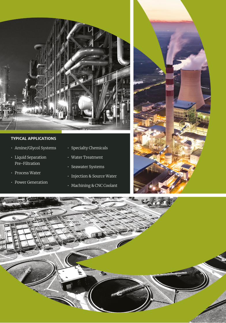
TYPICAL APPLICATIONS
• Amine/Glycol Systems
• Liquid Separation Pre-Filtration
• Process Water
• Power Generation
• Specialty Chemicals
• Water Treatment
• Seawater Systems
• Injection & Source Water
• Machining & CNC Coolant

Standard HC Filter sizes and ratings
Vessel details as listed are indicative. Please consult with the factory for application specific sizing based on actual process flowrates, fluid characteristics, contaminant loadings & filtration ratings.
HIGH-CAPACITY FILTRATION DESIGNED FOR YOUCeleros Flow Technology offers a range of HC Filtration options, so customers can choose the best solution for their needs. Our OEM expertise means we can design, manufacture and deliver a bespoke HC filtration system to precisely match your operational parameters.
VESSEL SPECIFICATION
Material of Construction: Carbon Steel / Stainless Steel / Alloy Steels
Design Code: ASME VIII Div.1 (Latest) incl. U-1A
Design Pressure: 40 barg (ANSI 300) as standard
Design Temperature: 80°C as standard
Access: ANSI B16.5 / B16.47 as standard – QOC if specified
Model Vessel Diameter NB
Standard Process Connection
Cartridge Quantity Max. Rated Flow (gpm)
Vessel Length L (mm)
40” 60” 40” 60”
HC-U080301XXYYZM 8” 3” 01 350 500 1690 2250
HC-U160602XXYYZM 16” 6” 02 700 1,000 1830 2520
HC-U180803XXYYZM 18” 8” 03 1,050 1,500 1890 2640
HC-U200805XXYYZM 20” 8” 05 1,750 2,500 1920 2640
HC-U241008XXYYZM 24” 10” 08 2,800 4,000 2150 2810
HC-U301212XXYYZM 30” 12” 12 4,200 6,000 2380 3060
HC-U321615XXYYZM 32” 16” 15 5,250 7,500 2460 3130
HC-U362019XXYYZM 36” 20” 19 6,650 9,500 2550 3250

FILTER CARTRIDGEA unique filter design with a layered and pleated media pack construction is central to the success of our HC Filtration solutions. The filter is contained within a cartridge that features an inside-to-out flow pattern. This ensures that solid contaminants are trapped and held within the cartridge and cannot accidentally fall into the clean side of the filter housing during replacement.
• High volume contaminant removal to β5000 efficiency
• Excellent particulate retention across a range of sizes
• Minimal impact on process parameters
• Quick and easy filter cartridge removal/replacement
• Extended service life
Designed for a maximum flowrate of 500 USgpm, HC Filter cartridges are available as standard in a range of lengths and particulate sizes.
Orientation Vessel Diameter
Process Connection
Cartridge Quantity
Micron Rating
Cartridge Length
Flange Rating
Vessel Material
H Horizontal 08 03 01 01 20
20”1
ANSI S150A
Alloy
V Vertical 16 06 02 02 40
40”3
ANSI S300C
Carbon
18 08 03 05 60 60”
6 ANSI S600*
S Stainless
20 08 05 10
24 10 08 20
30 12 12 40
32 16 15 70
36 20 19 90
HC - U _ _ _ XX YY Z M
Cartridge Diameter 6” End Caps Glass Filled PolypropyleneGlass Filled Acetal
Cartridge Length 20”, 40”, 60” O-Ring Material EPDMFKM
BUNA-NNeoprene
Rated Flow Rate (USgpm) 175, 350, 500 Micron Ratings (µm) 1, 2, 5, 10, 20, 40, 70, 90
Filtration Media PolypropyleneGlass Fibre w/ Polyester
Polyester
Retention Ratings B5000 (99.98% )
Maximum Service Temperature
Polypropylene – 82°CGlass Fibre w/ Polyester – 120°C
Maximum Differential Pressure 2.5 – 3.0 barg Changeout
Support Material PolypropylenePolyester / Nylon
Stainless Steel
Flow Direction In to Out
Standard HC Filter sizes and ratings
FILTER CONFIGURATIONSThe table below shows how to compile a standard HC Filter part number. Please consult with the factory for Series 600 applications.

Celeros Flow Technology reserves the right to incorporate our latest design and material changes without notice or obligations. Design features, materials of construction and dimensional data, as described in this bulletin, are provided for your information only and should not be relied upon unless confirmed in writing. Please contact your local sales representative for product availability in your region. For more information visit www.celerosft.com. COPYRIGHT © 2021 Celeros Flow Technology. DL_526_02_HIG-CAP-FIL_GB
www.celerosft.com
MIDDLE EASTDubai, U.A.E. P: +971 4 5289 555
USHouston, TX P: +1 800 344 2611
EUROPEKillarney, Ireland P: +353 64 6633322Newbury, UK P: +44 1635 42363
ASIAJaipur, India P: +91 141 239 8154
UNSURE OF YOUR CONTAMINANT LOAD? Consult with our Sales & Process Engineering teams regarding the benefits of the Filtration Testing services offered by Celeros Flow Technology. Accurate contaminant load analysis & determination allows for a more targeted & cost-effective filtration solution specific to your application.
Email our teamsE: [email protected]: [email protected]
SELECTIONDiscuss your requirements with the Celeros FT team to ensure that you are entirely satisfied with the suitability of the chosen filtration equipment for your intended application.
INSTALLATION Direction is critical to the operation and performance of Celeros FT HC Filters. The filter cartridges must be fitted such that flow is from the inside of the element to the outside. Inlet and outlet connections are clearly identified on the equipment General Arrangement drawings.
OPERATION Always observe the pressure and temperature limits, and make sure that the equipment is being used and operated correctly.
MAINTENANCE Replace filter cartridge elements when the maximum ΔP (changeout pressure) across the filter has been reached. Failure to do so may cause damage to the filtration membrane and allow debris to pass into the process downstream of the filter.
GETTING THE MOST FROM YOUR CELEROS FT HIGH- CAPACITY FILTRATION SOLUTION