Embed Size (px)
Citation preview

HI-EFFICIENTDIRECT VENTWALL FURNACE
- Do not store or use gasoline or other flammable vaporsand liquids in the vicinity of this or any other appliance.
- WHAT TO DO IF YOU SMELL GAS: • Do not try to light any appliance. • Do not touch any electrical switch; do not use any
phone in your building. • Immediately call your gas supplier from a neighbor’s
phone. Follow the gas supplier’s instructions. • If you cannot reach your gas supplier, call the
fire department.
- INSTALLATION AND SERVICE MUST BE PER-FORMED BY A QUALIFIED INSTALLER,SERVICE AGENCY OR THE GAS SUPPLIER.
WARNING: If the information in these instructions are not followed exactly, a fire or explosion may result causing property damage, personal injury or death.
HEDV25
HEDV40
Remove cabinet to access gas control knob.
WARNING: Operation of this furnace without the properly installed, factory furnished vent systemand vent cap could result in Carbon Monoxide (CO) poisoning and possible death. For your safety,this furnace and the vent system should be inspected at least annually by a qualified service technician.
This unit is for residential use only and is not approved for installation in greenhouses, or environ-ments involving dusty, wet, corrosive, or explosive conditions. Such conditions will invalidate thewarranty and may create unsafe conditions.
This appliance may be installed in an aftermarket, permanently located, manufactured home (USAonly) or mobile home, where not prohibited by local codes. This appliance is only for use with thetype of gas indicated on the rating plate. This appliance is not convertible for use with other gases,unless a certified kit is used.
MODEL NUMBERS NAT. GAS HEDV253A HEDV403A
L.P. GAS HEDV254A HEDV404A
Installation, maintenance, service, trouble shooting and repairs must be performed by a qualifiedservice agency. Mr./Mrs. Homeowner, do not attempt any of these procedures yourself as this couldexpose you to property damage, personal injury, or loss of life and will invalidate all warranties.
INSTALLATION ANDOPERATING INSTRUCTIONS
P/N 72903 / JUNE 2015
INSTALLER: Leave this manual with theappliance.CONSUMER: Retain this manual for future
reference.

Page 2
INTRODUCTION
THIS IS A GAS-FIRED DRAFT INDUCED, POWER DEPENDENT DIRECT VENT WALL FURNACETHAT WILL OPERATE SAFELY AND PROVIDE AN EFFICIENT SOURCE OF HEAT WHENINSTALLED, OPERATED AND MAINTAINED AS RECOMMENDED IN THESE INSTALLATIONAND OPERATING INSTRUCTIONS. READ THESE INSTRUCTIONS THOROUGHLY BEFOREINSTALLING, SERVICING, OR USING THE APPLIANCE. IF YOU DO NOT UNDERSTAND ANYPART OF THESE INSTRUCTIONS CONSULT LOCAL AUTHORITIES, OTHER QUALIFIEDINSTALLER, SERVICE TECHNICIAN, THE GAS SUPPLIER OR THE MANUFACTURER.
SPECIFICATIONS AND DIMENSIONS
Your Direct Vent Wall Furnace is shipped complete in one carton. This carton contains the furnace, ventcap, collector box, vent exhaust tube, air inlet tube, wall template with rough-in dimensions, installationand operating instructions, and wall thermostat.
Introduction…………………………...….. 2Specifications and Dimensions…………. 2Safety Rules………………………............. 3Clearances…………………………..……. 4/5Location…………………………..….…… 6/7Installation…………………………...…… 7/9Lighting Instructions……………….…… 10Burner Orifice………………………...….. 11
Removing Main Burner…....…………… 11Proper Burner Flame......………………… 11Wiring Diagram..........…………………… 12Sequence of Operation…………...……. 13Optional Kits……………………….…… 14/16Maintenance Instr./Service Record…... 17Trouble Shooting...........……………….. 18/19Parts Drawing…….....…………………... 20Parts List ............………………………... 21Warranty.................................................... 22
CONTENTS
Center Model Input Type Gas Vent MAX. MIN. No. BTU/HR Weight Width Depth Height Control CFM AMPS Conn. to Floor Wall Wall
(Adj.) THICKNESS
NATURAL GAS HEDV253A 25,000 100 Lbs.24-1/2” 9-3/4” 32-1/4” 24 V. 200 1.88 3/8” 12-1/2” 32” 5” HEDV403A 40,000 120 Lbs.34-5/8” 9-3/4” 30-1/2” 24 V. 500 2.18 3/8” 12-1/2” 32” 5”
L.P. GAS HEDV254A 25,000 100 Lbs.24-1/2” 9-3/4” 32-1/4” 24 V. 200 1.88 3/8” 12-1/2” 32” 5” HEDV404A 40,000 120 Lbs.34-5/8” 9-3/4” 30-1/2” 24 V. 500 2.18 3/8” 12-1/2” 32” 5”
The State of Massachusetts requires that installation and service of a gasappliance be performed by a plumber or gas fitter licensed in the
Commonwealth of Massachusetts.

SAFETY RULES
1. Improper installation, adjustment, alteration, service, or maintenance can cause property damage, bodilyinjury, or death.
2. Use in other than a residential application may result in unsatisfactory performance, may create unsafeconditions and will invalidate the warranty.
3. The installation must conform with local codes or in the absence of local codes wtih the National FuelGas Code, ANSI Z223.1/NFPA 54, Natural Gas and Propane Installation Code, CSA B149.1.
4. DO NOT INSTALL THIS FURNACE IN A RECREATIONAL VEHICLE OR TRAILER.5. Do not operate wall furnace unless it is connected to the factory supplied vent system with vent cap in
place.6. Check the rating label attached to the wall furnace to be sure it is equipped for the type gas you intend to
use.7. Never use a match, candle, flame or other source of ignition to check for gas leaks. Use only soapy water
or liquid detergent.8. Have your wall furnace and vent system inspected at least annually by a qualified service technician.9. Before cleaning or servicing, turn off the gas and allow furnace to cool.10. Do not operate wall furnace without all components properly installed (top, front, etc.).11. Due to high temperatures, the appliance should be located out of traffic and away from furniture and
drapes.12. Children and adults should be alerted to the hazards of high surface temperature and should stay away
to avoid burns or clothing ignition.13. Young children should be carefully supervised when they are in the same room as the appliance.14. Clothing or other flammable material should not be placed on or near the appliance.15. INSTALLATION AND REPAIR SHOULD BE DONE BY A QUALIFIED SERVICE TECHNICIAN.
THE APPLIANCE SHOULD BE INSPECTED BEFORE USE AND AT LEAST ANNUALLY BY AQUALIFIED SERVICE TECHNICIAN. More frequent cleaning may be required due to excessive lintfrom carpeting, bedding material, etc. It is imperative that control compartments, burners, and circulatingair passageways of the appliance be kept clean.
16. Do not install in a closet, alcove, or small hallway where the furnace could be isolated from the space tobe heated by closing a door.
17. Do not put anything around the furnace or vent cap that will obstruct the flow of combustion andventilation air.
18. The appliance, when installed, must be electrically grounded in accordance with local codes or, in theabsence of local codes, with the latest edition of National Electrical Code, ANSI/NFPA 70, or CanadianElectrical Code, CSA C22.1, if an external electrical source is utilized.
19. Never operate this furnace without the sight glass in place or with the glass broken or missing.20. If it is suspected that rising water may enter the furnace, turn off the gas immediately.21. Do not use this appliance if any part has been under water. Immediately call a qualified service techni-
cian to inspect the appliance and to replace any part of the control system and any gas control which hasbeen under water.
22. It is necessary to replace damaged gaskets or sealing material within the vent or air intake system. Failureto do so may result in property damage, personal injury or loss of life.
23. Any safety screen or guard removed for servicing must be replaced prior to operating heater.24. A gas appliance must not be connected to a chimney flue serving a separate solid fuel burning appliance.25. The appliance area must be kept clear and free from combustilbe materials, gasoline and other flammable
vapors and liquids.26. Any safety screen or guard removed for servicing an appliance must be replaced prior to operating the
appliance.
Page 3

VENT TERMINAL CLEARANCES
Page 4
REFERENCE LETTER TO DRAWING
CANADIAN INSTALLATIONS¹
U.S. INSTALLATIONS²
A = Clearance above grade, veranda, porch, deck, or balcony
12 Inches (30 cm) 12 Inches (30 cm)
B = Clearance to window or door that may be opened
12 Inches (30 cm) 9 Inches (23 cm)
C = Clearance to permanently closed window
12 Inches (30 cm) 9 Inches (23 cm)
D = Vertical clearance to ventilated soffit located above the terminal within a horizontal distance of 2 Feet (61 cm) from the center line of the terminal
18 Inches (46 cm) 18 Inches (46 cm)
E = Clearance to unventilated soffit
18 Inches (46 cm) 18 Inches (46 cm)
F = Clearance to outside corner 12 Inches (30 cm) 12 Inches (30 cm) G = Clearance to inside corner 12 Inches (30 cm) 12 Inches (30 cm) H = Clearance to each side of center line extended above meter/ regulator assembly
3 Feet (91 cm) within a height 15 Feet (4.5m) above the meter/regulator assembly
Clearances are in accordance with local installation codes and the requirements of the gas supplier
I = Clearance to service regulator vent outlet
3 Feet (91 cm) Clearances are in accordance with local installation codes and the requirements of the gas supplier
J = Clearance to nonmechanical air supply inlet to building or the combustion air inlet to any other appliance
12 Inches (30 cm) 12 Inches (30 cm)
K = Clearance to a mechanical air supply inlet
6 Feet (1.83 m) 3 Feet (91 cm) above if within 10 Feet (3 m) horizontally
L = Clearance above paved sidewalk or paved driveway located on public property
7 Feet (2.13m) A vent shall not terminate directly above a sidewalk or paved driveway that is located between two single family dwellings and serves both dwellings.
Clearances are in accordance with local installation codes and the requirements of the gas supplier.
M = Clearance under veranda, porch, deck, or balcony
12 Inches (30 cm) permitted only if veranda, porch, deck, or balcony is fully open on a minimum of two sides.
Clearances are in accordance with local installation codes and the requirements of the gas supplier.
¹ In accordance with the current CSA-B149.1 Natural Gas and Propane Installation Code ² In accordance with the current ANSI Z223.1 / NFPA 54 National Fuel Gas Code
Vent Terminal Air Supply Inlet Area where terminal is not permitted
FIGURE 1
Page 5
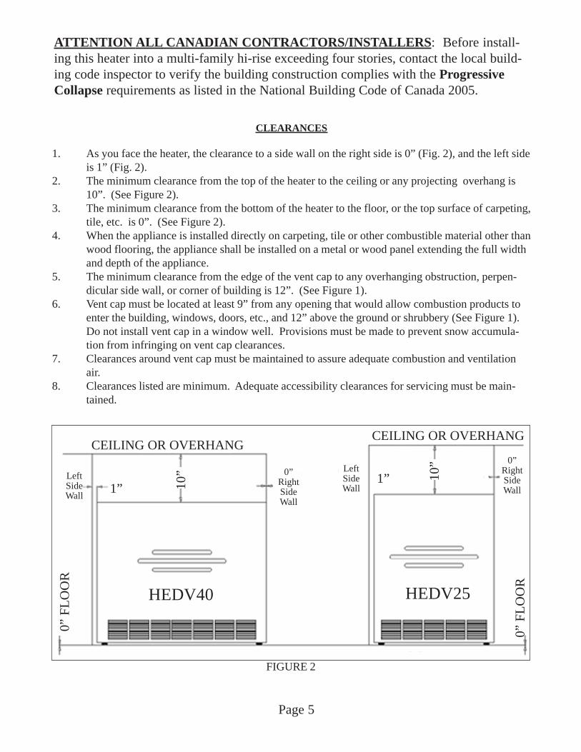
CLEARANCES
1. As you face the heater, the clearance to a side wall on the right side is 0” (Fig. 2), and the left sideis 1” (Fig. 2).
2. The minimum clearance from the top of the heater to the ceiling or any projecting overhang is10”. (See Figure 2).
3. The minimum clearance from the bottom of the heater to the floor, or the top surface of carpeting,tile, etc. is 0”. (See Figure 2).
4. When the appliance is installed directly on carpeting, tile or other combustible material other thanwood flooring, the appliance shall be installed on a metal or wood panel extending the full widthand depth of the appliance.
5. The minimum clearance from the edge of the vent cap to any overhanging obstruction, perpen-dicular side wall, or corner of building is 12”. (See Figure 1).
6. Vent cap must be located at least 9” from any opening that would allow combustion products toenter the building, windows, doors, etc., and 12” above the ground or shrubbery (See Figure 1).Do not install vent cap in a window well. Provisions must be made to prevent snow accumula-tion from infringing on vent cap clearances.
7. Clearances around vent cap must be maintained to assure adequate combustion and ventilationair.
8. Clearances listed are minimum. Adequate accessibility clearances for servicing must be main-tained.
0” F
LO
OR
0” F
LO
OR
HEDV40 HEDV25
10” 10
”CEILING OR OVERHANG
CEILING OR OVERHANG
1”1”
LeftSideWall
0”RightSideWall
0”RightSideWall
LeftSideWall
FIGURE 2
ATTENTION ALL CANADIAN CONTRACTORS/INSTALLERS: Before install-ing this heater into a multi-family hi-rise exceeding four stories, contact the local build-ing code inspector to verify the building construction complies with the ProgressiveCollapse requirements as listed in the National Building Code of Canada 2005.

CLEARANCES
9. RESIDENTIAL GARAGE INSTALLATION: Gas utilization equipment in residential garagesshall be installed so that all burners and burner ignition devices are located not less than 18 inches(46 cm) above the floor. You must build a platform 18” above floor, the full width and depth of theheater, including the rear trim kit. HEATER IS NOT DESIGNED TO HANG ON WALL.Unit should be located or protected so it is not subject to damage by a moving vehicle. Use care inselecting a good location within the garage. DO NOT locate the appliance where heated air will bedirected onto a nearby parked vehicle. Paint may discolor or rubber may harden and crack. DONOT allow open or closed containers of paint, gasoline or other liquids having flammable vapors tobe stored or used in the same area as the heater.
LOCATION
1. The wall furnace must be installed on an outside wall, unless optional Kit No. HEVK-5 is used.2. For most efficient performance, locate furnace as centrally as possible in the area to be heated and
where occupants may move about freely without coming into contact with the cabinet, and withinreach of a 115V wall outlet.
3. If the furnace is installed in a basement, a 12” clearance must be maintained between groundlevel and the bottom of the vent cap. Do not install furnace where vent cap will terminate in awindow well or any other opening below ground level. (See Figure 3). Do not allow snowaccumulation to build up within 12” of the vent cap.
OPTIONAL KITS
1. HEVK-5 - To extend vent 5 foot from heater. This will allow vent cap to be installed abovegrade from basement or to an outside wall. A total of 3 kits with 2 additional elbows may beused.
Page 6
12” Minimum above grade without excavation
FIGURE 3

INSTALLATION
Failure to follow these instructions carefully could result in poor performance, property damage, personal injury,or death.
STEP 1. LOCATE VENT OPENING (Requires 3-1/2” diameter wall opening)a) Select area on wall where heater will be installed. Using template (packed with heater) mark shaded area
where hole can be cut and to locate the wall brackets. (See Figure 4).b) Locate studs on each side of this area.c) Mark location for 3-1/2” diameter hole between studs. Hole should be offset to miss studs. (See Fig. 4).d) Check outside wall at this location for proper clearances around vent cap. (See Fig. 1).e) Cut vent openings into both the inside and outside walls, being sure to maintain level across both open-
ings.
STEP 2. ROUGH-IN GAS SUPPLY (See Figure 5)
Install at least 3/8” gas supply line. Contact local gas supplier if any questions.
Install a drip leg in gas supply line immediately upstream from the gas connection to heater (see localcodes), and provide a 1/8” N.P.T. plugged tapping, accessible for test gauge connection and an indi-vidual manual shut off valve accessible within room where heater is installed. (See Figure 5). Theheater and its individual shut off valve must be disconnected from the gas supply piping system duringany pressure testing of that system at test pressures in excess of 1/2 psig (3.5Pa). The heater must beisolated from the gas supply piping system by closing its individual manual shut off valve during anypressure testing of the gas supply piping system at test pressures equal to or less than 1/2 psig (3.5Pa).Test all connections for leaks using a soapy solution. NEVER USE AN OPEN FLAME TO TEST FORLEAKS.
The maximum inlet gas supply pressure for Natural or L.P./Propane gas is 1/2 p.s.i. or 14” w.c.The minimum inlet gas supply pressure for the purpose of adjustment is 4.5” w.c. for Natural gas or 11.0” w.c. forL.P./Propane gas.
Page 7
FIGURE 5
Gas Valve
Back ofheater
Wall
Gas SupplyDripLeg
Manual shut-off valvemust be accessible inroom where heater is
installed
Manual shut off valve with1/8” NPT plugged tappingMust be accessible in room
where heater is installed
3/8” Black iron pipe
Template
ShadedArea
WallStuds
16” O.C.
FIGURE 4
ATTENTION ALL CANADIAN CONTRACTORS/INSTALLERS: Before installingthis heater into a multi-family hi-rise exceeding four stories, contact the local buildingcode inspector to verify the building construction complies with the Progressive Col-
lapse requirements as listed in the National Building Code of Canada 2005.

INSTALLATION - CONTINUED
STEP 3 INSTALLING VENT SYSTEM 5” - 32” WALL THICKNESS (12.7 cm - 81.3 cm)a) Use only factory supplied parts. Do not attempt to modify in any way. To do so could cause a system
imbalance resulting in poor performance and/or unsafe operating conditions.b) Slide collection box pipes through cutout and secure collection box to inside wall. Anchors (not sup-
plied)may be required. (See Figure 5).
c) From outside house, mark collection box pipes and cut off 1/2” beyond outside wall.d) Slide vent cap pipes onto collection box pipes and push in until flange is flush against house. Secure vent
cap assembly to outside wall with a slight downward slope. This will prevent water from entering andallow condensation to drain. Caulk around the edges of the vent cap mounting plate. NOTE: It maybe necessary to build a metal or wood frame to provide a flat surface for the mounting plate to be flushagainst or to attain the 5” minimum wall thickness.
Page 8
FIGURE 5
6-1/4”(15.9 cm)
Trim Kit Brackets
Gas Inlet
Air Intake
Flue Outlet
6-1/8”(15.6 cm)
4-1/8”(10.2 cm)
25”
(63.
5 cm
)
20-1
1/16
”(5
2.5
cm)
7-9/
16”
(19.
2 cm
)
HEDV40 - Figure 6
6-3/8”(16.2 cm)
4”(10.2 cm)
29-5
/8”
(75.
2 cm
)
25-1
/16”
(63.
7 cm
)7-
9/16
”(1
9.2
cm)
5-7/8”(14.9 cm)
Trim Kit Brackets
Gas Inlet
Air Intake
Flue Outlet
HEDV25 - Figure 6
Collection BoxAssembly
Vent CapAssembly
Vent CapMounting
Plate
FIGURE 7FIGURE 8

Page 9
STEP 4. INSTALLING HEATERa) Locate (and mark) wall mounting bracket location on wall using template supplied.b) Secure wall brackets to wall, anchors (not provided) may be required.c) Secure trim kit brackets to back of heater using eight #8 screws provided. (See Figure 9).d) Slide heater to approximately 5” of wall.e) Secure air intake hose to back of heater and the collector box assembly using hose clamps provided. (See
Figure 8).f) Secure vent exhaust tube to exhaust tube on back of heater and the exhaust tube on the collection box
assembly using hose clamps provided. (See Figure 8).g) Connect 3/8” minimum gas supply line to manual cut-off valve on back of the heater. (See Figure 5).h) Locate factory installed thermostat wires extending from rear of the heater. Connect 24 V. thermostat
wall thermostat (provided) using a maximum 20’ of thermostat wire. Do NOT splice thermostat wire.i) Secure right and left trim side panels to the wall and trim kit brackets with eight #8 screws provided.
(See Figure 9). This will space the back of the heater 5” from the wall.j) Secure trim top to trim sides using four #8 screws provided.k) Plug three-pronged factory wired power cord into a properly grounded 115 Volt electrical outlet. NEVER
use an extension cord. If homeowner desires, heater can be hard wired by a licensed electrician. Seelocal electrical codes.
l) Turn the manual gas control valve on. Check all connections for leaks using a soapy solution. NEVERcheck for leaks with an open flame.
HEATER IS NOW INSTALLED, FOLLOW LIGHTING INSTRUCTIONS TO PLACE HEATER INTO SER-VICE. FRONT PANEL MUST BE REMOVED FOR ACCESS TO LIGHTING INSTRUCTIONS AND GASCONTROL.
FIGURE 9
Trim Kit Top
1/2”Bushing
Trim KitLeft Side
Trim KitBracket (4)
Trim KitRight Side

OPERATING INSTRUCTIONS
TO TURN OFF GAS TO APPLIANCE
1. Set the thermostat to lowest setting. 2. Turn off all electric power to the appliance if service is to be performed. 3. Turn gas control knob clockwise to “OFF”. Do not force.
A. This appliance does not have a pilot. It is - If you cannot reach your gas supplier, callequipped with an ignition device which the fire department.automatically lights the burner. Do not tryto light the burner by hand. C. Use only your hand to push in or turn the gas
control knob. Never use tools. If the knob willB. BEFORE OPERATING smell all around the not push in or turn by hand, don’t try to repair
appliance area for gas. Be sure to smell next it, call a qualified service technician. Force orto the floor because some gas is heavier than attempted repair may result in a fire or explosion.air and will settle on the floor.
WHAT TO DO IF YOU SMELL GAS: D. Do not use this appliance if any part has been- Do not try to light any appliance. under water. Immediately call a qualified service- Do not touch any electric switch; do not technician to inspect the appliance and to use any phone in your building. replace any part of the control system and any- Immediately call your gas supplier from a gas control which has been under water. neighbor’s phone. Follow the gas supplier’s instructions.
FOR YOUR SAFETY READ BEFORE OPERATING
WARNING: If you do not follow these instructions exactly, a fire or explosion may resultcausing property damage, personal injury or loss of life.
Gas control knob shownin “OFF” position
1. STOP! Read safety information on this label. 7. Wait five (5) minutes to clear out any gas. If 2. Set the thermostat to the lowest setting. you smell gas, STOP! Follow “B” in safety 3. Turn off all electric power to the appliance. information on this label. If you don’t smell 4.. This appliance is equipped with an ignition device gas, go to next step.
which automatically lights the burner. Do not try 8. Turn gas control knob counterclockwise to light the burner by hand. to “ON”.
5. Remove cabinet to access gas control knob. 9. Turn on all electric power to the appliance. 6. Turn gas control knob clockwise to 10. Set thermostat to desired setting.
“off”. Do not force. 11. If the appliance does not operate, followinstructions “To Turn Off Gas To Appliance”and call your service technician or gassupplier.
12. Replace cabinet.
Page 10

Page 11
NOTE: THE FURNACE AND ALL COMPO-NENTS MUST BE INSPECTED AT LEASTANNUALLY BY A QUALIFIED SERVICETECHNICIAN. THIS SHOULD INCLUDE THEBURNER, HEAT EXCHANGER, AND VENTSYSTEM. BE SURE THAT THE FLOW OFCOMBUSTION AND VENTILATION AIR ARENOT OBSTRUCTED AND THAT ALL HOSESARE UNDAMAGED, AND ALL CLAMPS ARESECURELY TIGHTENTED.
Primary Flame
Burner
Secondary Flame
Heat Exchanger Tube
FIGURE 10
FIGURE 11
BurnerBox Top
Manifold
BurnerBurnerBracket
Direct Spark Ignitor
MaxitrolGas Valve
MODEL 0 to 2,000’ 4,000’ 6,000’ 8,000’ - NO. 2,000’ 4,000’ 6,000’ 8,000’ 10,000’
NATURAL GAS HEDV253A 51 52 52 53 54 HEDV403A 45 47 48 49 50
L.P. GAS HEDV254A 58 60 62 63 64 HEDV404A 55 55 56 56 57
PROPER BURNER FLAMEThe burner flame may be observed by raising the sightglass cover. A proper flame will have a dark blue innermantle, with a lighter blue outer mantle that extends fromthe burner into the heat exchanger tube, (see Figure 10).There is no primary air adjustment on the burner, and properflame is assured since the correct manifold pressure andorificing have been done at the factory.
TO REMOVE MAIN BURNER FORINSPECTION AND CLEANING
1. Turn off all electrical supply to heater. 2. Turn off gas supply. 3. Remove front panel. 4. Unplug wire to direct spark ignitor and sensor.
(See Fig. 11.) 5. Disconnect vacuum hose from burner box. 6. Remove screws holding burner box top to
burner box. (See Figure 11.) 7. Remove burner plate and burner box top. Take
care not to contact, or strain ignitor in any wayas it is extremely fragile. (See Figure 11.)
8. Remove 2 nuts holding burner bracket. (SeeFigure 11).
9. Slide burners toward heat exchanger and lift upfrom rear and back. (See Figure 11).
10. Clean or replace as needed.11. Reinstall by reversing Steps 9 - 1.
BURNER ORIFICEThis appliance equipped only for altitudes 0 - 2,000 ft.Appliance input ratings are based on sea level operationand need not be changed for operation up to 2,000 feet(609.9 m) elevation. For operation at elevations above2,000 feet (609.9 m).
The BTU input must be reduced 4% per 1,000 ft. Orificechange must be completed by a qualified installer or ser-vice technician. See the following orifice chart for theproper orifice drill size for a specific elevation.
SPECIFIC ELEVATIONS

WIRING
This appliance is equipped with a three prong power cordwith grounding plug. For your protection against shockhazard, this appliance should be plugged directly into aproperly grounded three-prong receptacle. Do not cut orremove the grounding prong from this plug.
NOTE: If any of the original wire supplied with thisappliance has to be replaced, it must be replaced withtype 105ºC wire or its equivalent.
CAUTION: Label all wires prior to disconnection whenservicing controls. Wiring errors can cause improper anddangerous operation.
Verify proper operation after servicing.
WARNINGTHIS IS A GAS-FIRED APPLIANCE. KEEP THEAREA CLEAR OF GASOLINE AND OTHER FLAM-MABLE VAPORS AND LIQUIDS. ALL COMBUS-TIBLE MATERIAL MUST BE KEPT CLEAR OF THISAREA TO AVOID FIRE OR EXPLOSION.
Page 12
GroundBrown 24 VAC
HEDV25-A, HEDV40-APICTORIAL
Thermostat
Pur
ple Red
Whi
te
Bla
ck
Bla
ck
Ora
nge
Red
Black
Black
R G W C
PressureSwitch
GasValve
DraftInducer
CirculatingBlower
LimitSwitch
Yellow
24 V
CMB Blower
C i r c u i tBoard
Transformer
Black
ACCAC8 COOL
L1
Blue
24VAC
Green
HEDV25-A,HEDV40-ALADDER
Gas Valve
P r e s s u r eSwitch
Limit Switch
Thermostat
CIRCUIT BOARD
115 VAC
Draft Inducer
CirculatingBlower
HEDV253A, HEDV254A, HEDV403A, & HEDV404AWIRING DIAGRAM

Page 13
Pre
ssur
e sw
itch
clos
es p
rovi
ngin
duce
r
Hea
ter
inst
and-
by
The
rmos
tat
calls
for
heat
Pow
eron
to
draf
tin
duce
r
Pre
ssur
esw
itch
clos
esin
duce
rpr
oved
Spa
rkig
nitio
nen
ergi
zed
Gas
valv
eop
ens
gas
flow
tobu
rner
Bur
ner
flam
epr
oved
Blo
wer
onH
eat
cycl
eT
herm
osta
tsa
tisfi
ed
Gas
valv
ecl
oses
gas
flow
to b
urne
rsof
f
Dra
ftin
duce
rof
f
Blo
wer
off
Hea
ter
inst
and-
by
Indu
cer
cont
inue
s to
run
O
ne H
our
Loc
k O
ut
15 S
ec.
inte
rpu
rge
3 A
ttem
pts
for i
gniti
on
30 S
ec.
180
Sec
.90
Sec
.4
Sec
.
NO
NO
YES
YES
NO
NO
YE
SY
ES
ST
EP
#1)
The
rmos
tat c
alls
for
hea
t.2)
Dra
ft I
nduc
er tu
rns
on.
3)P
ress
ure
swit
ch c
lose
s.4)
Spa
rk ig
niti
on b
egin
s.5)
Gas
flo
w to
bur
ner.
6)B
urne
r ig
niti
on p
rove
n.7)
Cir
cula
ting
Blo
wer
on.
8)H
eate
r bur
ns th
roug
h he
atin
g cy
cle.
9)T
herm
osta
t sat
isfi
ed.
10)
Gas
flo
w o
ff to
bur
ner.
11)
Dra
ft in
duce
r of
f.12
)C
ircu
lati
ng B
low
ers
off.
13)
Hea
ter i
n st
and-
by.
NO
TE
: IF
TH
ER
E I
S A
MA
LF
UN
CT
ION
IN
ST
EP
S 3
, 5, 6
TH
E O
PE
RA
TIO
N S
EQ
UE
NC
E W
ILL
ST
OP
AT
TH
AT
PO
INT.
FO
R S
TE
PS
5 O
R 6
, IF
AF
TE
R 2
AD
DIT
ION
AL
AT
TE
MP
TS
MA
LF
UN
CT
ION
ST
ILL
OC
CU
RS
, TH
EC
ON
TR
OL
WIL
L L
OC
K O
UT
FO
R O
NE
HO
UR
. F
OR
PU
RP
OS
E O
F T
ES
TIN
G, T
HE
ON
E H
OU
R L
OC
KO
UT
CA
NB
E O
VE
RR
IDD
EN
BY
RE
SE
TT
ING
TH
E T
HE
RM
OS
TAT
OR
IN
TE
RR
UP
TIN
G T
HE
EL
EC
TR
ICA
L P
OW
ER
.
HE
DV
SE
QU
EN
CE
OF
OP
ER
AT
ION

P/N 726122”x6’ BlackFlex Tubing
P/N 72532Use only if connecting
flex tubing of 2 ormore ktis
P/N 72575 2”x5’Black Flocked Tube
P/N 725932” Hose Clamps
P/N 41515Support
Brackets (2)
P/N 72578 2”x3”Black Silicone
Wrapped Coupling
P/N 41520Center Bracket
HEVK-5 5’ VENT EXHAUST KITINSTALLATION INSTRUCTIONS
WARNING: Use only Louisville Tin & Stove Company factory supplied parts and kits. Failure to do so could result in lossof life, personal injury, property damage, or unsatisfactory performance. This kit must be installed by a qualified installer orservice technician.
CONTENTS OF KIT1 only P/N 72532 2”x3” Steel Coupling 1 only P/N 41520 Center Bracket1 only P/N 72575 2”x5’ Black Flocked Tube 8 only P/N 72593 2” Hose Clamps1 only P/N 72612 2”x6’ Black Flex Tubing 1 only P/N 72578 2”x3” Black Silicone2 only P/N 41515 Support Brackets Wrapped CouplingSTEP 1 - LOCATE VENT OPENINGa) Select location on outside wall that vent will exit through.b) Check outside for proper clearances around vent cap. See installation instructions.c) Mark and cut 3-1/2” hole through both inside and outside walls, being sure to maintain level across both openings.d) Measure wall thickness. Mark and cut off both intake and exhaust pipes to 1/2” beyond outside wall.e) Secure collection box to wall. Wall anchors, not provided, may be required.STEP 2 - INSTALL HEATERa) Select location on wall where heater will be installed.b) Using wall template supplied with heater, mark location for trim kit wall brackets.c) Attach brackets to wall (wall anchors, not provided may be required) and back of heater. Using screws provided on
back of heater.d) Slide heater into position and secure brackets togehter. This should position back of heater 5” off wall.e) Select direction vent will exit trim kit, left, right, or straight up.f) Before installing trim kit remove knockout on this side.STEP 3 - INSTALL VENTa) Remove and discard P/N 72611 2”x24” black flex tubing from air inlet. (Save hose clamp).b) Attach P/N 72612 2”x6’ black flex tubing to air inlet. Secure with P/N 72593 2” hose clamp.c) Slide P/N 72575 2”x5’ flocked tube through trim kit opening (knockout) and attach to P/N 72610 orange silicone
90E elbow supplied with heater. Secure with 2” hose clamp.d) Attach P/N 41515 support brackets to wall. Wall anchors, not provided, may be required. Postion support brackets
within 8” from side of trim kit and end of pipe. Secure flex tubing and flocked tube to brackets using 2” hoseclamps.
e) Attach P/N 41520 center bracket 2-1/2’ from pipe end and insert flex tube through bracket. This will prevent theflex tube from touching the black flocked exhaust tube.
f) Connect flex air intake tube and flocked exhaust tube to collection box.g) Complete gas connection and attach trim kit to brackets.h) Follow lighting instructions.SPECIAL NOTESa) You may use up to three HEVK-5 Kits for a total of 15’ vent extension with two additional elbows. DO NOT
EXTEND VENT BEYOND 15’ OR USE MORE THAN THREE TOTAL ELBOWS (one elbow comes with theheater).
b) To connect two vent kits together use P/N 72532 2”x3” steel coupling. Secure with 2” hose clamps.c) If you are using one, two, or three kits, after installation is complete you will discard 2 P/N 72593 hose clamps and
one P/N 72532 steel coupling.d) If you need to make a 90E offset you will need to order P/N HEEL-1 90E Elbow Kit. Two offsets require two kits.e) If complete vent extension is horizontal, pipes may be sloped down slightly to allow any condensate to
drain through the exhaust pipe to the outside. DO NOT ALLOW TO DRAIN ONTO WALKWAY. If any part ofvent extension is vertical or local codes do not allow draining of condensate to outside you must add P/N 18900Condensate Kit.
f) For cosmetic purposes, the addition of the HEVK-5 Kit can be enclosed by adding a HEVE-5 Vent Enclosure Kit.To completely enclose the HEVK-5 Kit one HEVE-5 will be needed for each HEVK-5 used.
Page 14

HEVE-5VENT ENCLOSURE KIT
INSTALLATION INSTRUCTIONS
This kit must be installed by a qualified installer orservice technician.
STEP 1) Position end of Part No. 41610 enclosure body toheater trim kit where pipes exit trim kit, centeringpipes inside body and attach to wall. Wall anchors, not provided, may be required. Collector box maybe behind HEVE-5 Kit.
STEP 2) Cut to fit enclosure panel 1” beyond end of ventrun. Insert Part No. 41620 End Cap and attachusing three #8 screws provided.
SPECIAL INSTRUCTIONSSTEP 3) If more than one HEVE-5 Kit is used, attach Part
No. 72604 Trim Kit where ends meet.
STEP 4) If making a 90º turn, measure 1” beyond outsideturn and cut off enclosure panel. Notch panel onsurface of direction turn is being made to allowpipes to pass through into next HEVE-5 Kit.Attach second panel to wall and attach Part No.72604 Trim Kit where two bodies meet. Installend cap Part No. 41620.
Page 15
HEEL-190º ELBOW KIT
Contains 1 only P/N 72613 90º Elbow 2”

Page 16
72618 -Condensate Trap
80190 - Casing Black Plug
InducerDrain Cap
72538 -FlexHose
72539 - Hose Clamp (2)
50606 - #8x12 Screw(2)
FIGURE 2
WeldPin (2)
Condensate PanAssembly
Wing Nuts (2)
FIGURE 1
18900 CONDENSATE KITINSTRUCTIONS
HI-EFFICIENT DIRECT-VENT WALL FURNACE
Always use this kit when the vent has a vertical run, or where local codes prohibit draining condensate to the outside. Useonly Cozy Heating Systems supplied parts. Failure to use factory supplied parts or to follow these instructions may resultin unsatisfactory performance, property damage, personal injury and/or loss of life.
Before beginning kit installation, open carton and identify the following components.A) P/N 18910 Condensate Pan AssemblyB) P/N 72618 Condensate Trap AssemblyC) P/N 72538 3/8” TubingD) P/N 72539 3/8” Hose Clamp (2)E) P/N 50606 #8 x ½” screws (2)
Step 1. Set thermostat to “off” and allow heater to cool.Step 2. Turn off gas supply to heater.Step 3. Turn off electric power to heater.Step 4. Remove the cabinet.Step 5. Loosen the two wing nuts located in the heater base. See Figure 1.Step 6. Slide the condensate pan into the bottom of the heater with slots in tabs onto the weld studs and under the wing
nuts. Use care to not rip the insulation in bottom of heater. Tighten the wing nuts to secure condensate pan.See Figure 1.
Step 7. Remove and discard the button plug located at center lower area of heater back.Step 8. Attach condensate trap to heater back so bottom of trap is inside the bottom of the condensate pan. Secure
using the (2) #8 screws provided. Fill trap with water. See Figure 2.Step 9. Remove and discard plastic cap from bottom of the draft inducer drain tube. See Figure 2.Step 10. Connect the tubing to the draft inducer drain tube and the condensate trap. Secure both ends with two 3/8”
hose clamps provided. See Figure 2.Step 11. Fill the condensate pan with water.Step 12. Reverse steps 4 – 1. Follow lighting instructions to place heater in operation.
WARNING: The water level in the condensate pan must be checked and maintained to completely cover the condensatetrap. The water provides a seal to prevent combustion products from coming through the condensate trap and entering theliving area.
Form No. 72936

MAINTENANCE INSTRUCTIONS
For proper and safe operation keep furnace and furnace area clean. At regular intervals turn control valve to off, letcool and clean inside control and heat exchanger compartment. To clean front panel use only a damp cloth, do notuse any kind of solvent or cleaning fluid that could leave a residue to burn or give off fumes when furnace isturned on.
Have the furnace checked, cleaned, and repaired by a qualified service technician. Check venting system, andburner operation prior to use each year.
Follow a regular service and maintenance schedule for safe and efficient operation.
Do not obstruct combustion and ventilation air. Examine the venting system as a routine part of the safety perfor-mance check on an annual basis.
If the heat exchanger is removed, check the heat exchanger intake gasket and draft inducer gasket and replace if thereis any sign of damage. Be sure all gaskets are in place when the heat exchanger is replaced.
Failure to replace any gasket that has been damaged may result in property damage, personal injury or loss of life.Oil the bearings of the fan motor every 6 months with S.A.E. 20 oil.
SERVICE RECORD
------------------------------------------------------------------------------------------------------------------------------------------------------------------------------------------------------------------------------------------------------------------------------------------------------------------------------------------------------------------------------------------------------------------------------------------------------------------------------------------------------------------------------------------------------------------------------------------------------------------------------------------------------------------------------------------------------------------------------------------------------------------------------------------------------------------------------------------------------------------------------------------------------------------------------------------------------------------------------------------------------------------------------------------------------------------------------------------------------------------------------------------------------------------------------------------------------------------------------------------------------------------------------------------------------------------------------------------------------------------------------------------------------------------------------------------------------------
Page 17

TROUBLE SHOOTING CHART - For use by a qualified service technician.
Page 18
CORRECTIVE ACTION SYMPTOM POSSIBLE CAUSES To be taken by Contractor Flame too large 1. Defective operator section of valve. 1. Replace valve.
2. Burner orifice too large. 2. Check with local gas company for proper orifice - size and replace.
3. If installed above 2,000 ft. 3. See burner orifice section, Page 11.
Yellow burner flame 1. Clogged burner ports. 1. Remove burners and check for obstruc- tions in throats, ports, and orifices. Clean - but do not enlarge ports or orifices.
2. Obstruction around vent cap. 2. Make sure area around vent cap is clear, be sure vent system is sealed.
Gas odor 1. Gas leak. 1. See Page 1. Delayed Ignition 1. Low gas pressure. 1. Check gas supply pressure.
2. Igniter not properly located. 2. Check ignitor location and correct if necessary.
Failure to ignite 1. Main gas off. 1. Open manual gas valve.2. Thermostat not set high enough to call 2. Set thermostat to higher temperature. for heat.3. Clogged burner orifice. 3. Clean burner orifices (do not enlarge).4. Incorrect wiring. 4. Check wiring diagram.5. Defective valve. 5. Replace valve.6. No power to unit. 6. Plug in power supply cord. Check 115 V.
wall outlet. Burner won’t 1. Defective or damaged thermostat wire, 1. Can be checked by removing wire from con- turn off or thermostat. trol board terminal. If burner goes off, replace
thermostat.2. Thermostat location. 2.Re-locate out of drafts, hot, or cold spots.3. Defective or sticking valve. 3. Replace valve.4. Excessive gas pressure. 4. Contact utility supplying gas.5. Defective or damaged thermostat. 5. Replace thermostat.
Incorrect gas 1. Gas input not checked. 1. Re-check gas input. input 2. Clogged orifices. 2. Clean orifices with a smooth wood toothpick,
do not enlarge. Not enough heat 1. Furnace undersized. 1. This is especially true when a dwelling or
room is enlarged. Have the heat loss calculated and compare to furnace output. Your gas company can supply you with this information. If furnace is undersized, replace with correct size unit.
2. Thermostat temperature set too low. 2. Raise thermostat temperature setting.3. Incorrect supply pressure. 3. Check supply pressure.
Too much heat 1. Temperature set too high. 1. Lower temperature setting.2. Combination control valve stuck open. 2. Replace combination control valve.
Main burner 1. Defective flame sensor. 1. Check voltage and replace if low. goes out 2. Input too high. 2. Check input rate. during normal 3. Sight glass not air tight. 3. Tighten screws securing sight glass. Check operation and replace gasket if needed.
4. Vent tubes not properly installed or 4. Follow instructions. Check both exhaust and sealed. air intake tubes, and vent cap. Be sure all
gaskets are in place and properly sealed. Use only tubes and vent cap supplied. Do not alter vent tubes or cap.
5. Limit switch opens. 5. Check for blockage of discharge air.6. Exhaust or Air Intake tubes blocked. 6. Check for and remove any obstruction to
incoming circulating air.

# OF REASON FOR CORRECTIVE ACTION FLASHES INDICATION POSSIBLE CAUSES TO BE TAKEN BY CONTRACTOR
Slow Flash Normal operation,no call for heat
Fast Flash Normal operation,call for heat
2 System lockout a.) Defective ignitor. a.) Replace ignitor.failed to detect or b.) Ignitor cable defective. b.) Replace ignitor cable.sustain flame c.) Ignitor cable disconnected. c.) Connect ignitor cable.
d.) Manual gas valve in “OFF” d.) Turn manual gas valve to “ON”. position. No gas to valve.e.) Defective wire to gas valve. e.) Replace defective wire.f.) Wire to gas valve disconnected. f.) Connect gas valve wire.g.) Obstruction to vent outlet. g.) Remove obstruction.h.) Obstruction to air inlet. h.) Remove obstruction.
3 Pressure switch a.) Defective pressure switch. a.) Replace pressure switch.Open or Closed b.) Pressure switch tubing b.) Replace damaged tubing.
damaged, kinked or collapsed.c.) Pressure switch tubing c.) Connect pressure switch tubing. disconnected.d.) Defective draft inducer. d.) Replace draft inducer.e.) Pressure switch tubing to e.) Reverse tubing connections on wrong connection. pressure switch.
4 Limit Switch opens a.) Defective limit switch. a.) Replace limit switch.b.) Damaged limit switch wire. b.) Replace damaged wire.c.) Limit switch wire c.) Connect limit switch wire. disconnected.d.) Blockage in front of front d.) Remove blockage. panel.e.) Heater over rate. e.) Check orifice, pressures, rate.
5 Flame sensed gas a.) Defective gas valve. a.) Replace gas valve.valve not energized b.) Defective control module. b.) Replace control module.
Steady light Internal failure a.) Defective control module. a.) Replace control module. No Flashes (control module
failure and poweron self-check)
TROUBLE SHOOTING CHART - for use by a qualified service technician.
To assist in diagnosing and servicing, this heater is equipped with a self-diagnosingcontrol module. Should a malfunction occur, the green indicator light on the controlmodule will flash a varying number of times indicating the circuit in which malfunctionis located.
Page 19

HI-EFFICIENT DIRECT VENT WALL FURNACE
Prices and specifications subjectto change without notice.
All prices are F.O.B. factory.
Page 20
MODEL NUMBERSHEDV253A - NAT. GASHEDV403A - NAT. GAS
HEDV254A - L.P. GASHEDV404A - L.P. GAS
ATTN: CONTRACTORS AND SERVICE TECHNICIANS, we only sell parts through our wholesalers, but the priceslisted are for your convenience. For prompt parts service, contact the wholesaler from which you purchased your Cozy
heater. NOTE: Parts & schematic drawings on current models are shown at www.cozyheaters.com.
Rev. 05/2012
44
40
3
2
42
29
1
4
45
30
31
3233
35
3938
4123
2243
36
37
28
24
21
2015
14
1719
1816
1213
11
8 10
2776
9
5 26
25
47
46
34

Page 21 JUNE 2015
HOW TO PROPERLY ORDER PARTS: In addition to part description and part number, please give model number, serialnumber, and type of gas used. This information can be found on the rating plate that is attached to heater.
* Requires 2
REF. PART LIST PART LIST PART LIST PART LISTPART DESCRIPTION NO. NO. PRICE NO. PRICE NO. PRICE NO. PRICE
Cabinet 1 18020 18020 18520 18520Circulating Blower 2 72501 72501 72500 72500Limit Switch 3 72671 72671 72670 72670Front Heat Shield 4 18100 18100 18595 18595Tubular Heat Exchanger 5 72531 72531 72530 72530Cabinet Base Assembly 6 18120 18120 18620 18620Leg Leveler (4 Per) 7 80009 80009 80009 80009Draft Inducer Gasket - 7-3/4x9" 8 72565 72565 72565 72565Draft Inducer Mounting Plate Gasket 9 72563 72563 72563 72563Draft Inducer 10 72506 72506 72506 72506Sight Glass Frame 11 18185 18185 18185 18185Sight Glass 12 70150 70150 70150 70150Sight Glass Gasket - 2-5/8x1-3/8" 13 72564 72564 72564 72564Ignitor 14 64009 64009 64009 64009Ignitor Cable 15 64210 64210 64210 64210Burner Orifice (Requires 2) 16 *95251 *95258 *72156 *72139Burner 17 *72528 *72528 *72528 *72528Manifold 18 72640 72640 72640 72640Burner Box Assembly 19 18150 18150 18150 18150Burner Box Top Gasket - 6-3/4x6-1/2" 20 72567 72567 72567 72567Burner Box Top 21 18165 18165 18165 18165Gas Valve 22 64590 64591 64590 64591Gas Valve Support Bracket 23 18180 18180 18180 18180Burner Box Mounting Gasket - 7¾x3½" 24 72566 72566 72566 72566Transformer 25 78069 78069 78069 78069Circuit Board 26 64625 64625 64625 64625Wiring Harness 27 72675 72675 72675 72675Pressure Switch 28 72517 72517 72518 72518Casing Back 29 18090 18090 18590 18590Air Intake Hose 30 72611 72611 72611 726112" Hose Clamp (4 Per) 31 72593 72593 72593 72593Vent Cap Assembly 32 18250 18250 18650 18650Vent Cap Gasket - 4-3/32x4-3/32" 33 72608 72608 72608 72608Collection Box Assembly 34 18225 18225 18225 18225Collection Box Gasket - 5-7/16x5-7/16" 35 72607 72607 72607 72607Collection Box Cap 36 72587 72587 72587 72587Vent Exhaust Tube 37 72610 72610 72610 72610Trim Kit Bracket (Requires 4) 38 18320 18320 18320 18320Wall Mounting Bracket (Requires 4) 39 18315 18315 18315 18315Trim Kit, Left Side Panel 40 18310 18310 18310 18310Trim Kit, Right Side Panel 41 18305 18305 18305 18305Trim Kit Top 42 18300 18300 18700 18700HEDV Wire Bracket 43 18190 18190 18190 18190Liner, Left Side 44 18110 18110 18610 18610Liner Top 45 18075 18075 N/A N/AWall Thermostat, 24 Volt 46 78355 78355 78355 78355Draft Inducer Mounting Plate 47 18200 18200 18200 18200Thermostat Wire 20' N/A 74518 74518 74518 74518Power Cord N/A 64205 64205 64205 64205Manual Shut-off Valve (Off-On) N/A 64074 64074 64074 64074Condensate Kit N/A 18900 18900 18900 18900
HEDV403A HEDV404AHEDV253A HEDV254A
ATTN: CONTRACTORS AND SERVICE TECHNICIANS, we only sell parts through our wholesalers, but the prices listed above are for your convenience. For prompt parts service, contact the wholesaler from which you purchased your Cozy
heater. NOTE: Parts & schematic drawings on current models are shown at www.cozyheaters.com.

LIMITED WLIMITED WLIMITED WLIMITED WLIMITED WARRANTARRANTARRANTARRANTARRANTYYYYYCozy Heating Systems LLC warrants to the
original user the accompanying product for the period specified herein, provided said product is installed, operated, maintained, serviced, and used according to the instructions and specifications accompanying the product. AS OUTLINED IN OUR INSTRUCTIONS, ANY WARRANTY CONSIDERATIONS ARE CONTINGENT ON INSTALLATION BY A QUALIFIED INSTALLER (CONTRACTOR). SELF-INSTALLATION IS PROHIBITED AND WILL INVALIDATE YOUR WARRANTY. If within a period of one year from the date of installation of the product, any part supplied by the manufacturer proves to be defective due to workmanship or material, it will replace such part, provided parts have not been subjected to misuse, alteration, neglect, or accidents. The term of the warranty for the heat exchanger and burners is covered in Table A below. Any claim not made within ten (10) days after the expiration of the warranty period shall be deemed waived by the user. The manufacturer shall have no liability or be required to perform any obligation under this warranty unless, when requested, the user returns, at the user’s expense, the component or product claimed defective, to the manufacturer for inspection, to enable the manufacturer to determine if the claimed defect is covered by this warranty. No charges for freight, labor or other expenses incurred in the repair, removal, or replacement of any product or component claimed to be defective, will be paid by the manufacturer to the user, and the manufacturer will no t be liable for any expenses incurred, by the user, in remedying any defect in the product. Service under this warranty is the responsibility of the installer. In the event service
under this warranty is needed, the user of the product shall request such service directly from the installer. If the user is unable to locate the installer, the user should write directly to the manufacturer, and the name of an alternative service source will be supplied. The product safety registration card (packed inside the appliance) must be completed and returned to the factory. THIS WARRANTY IS EXPRESSLY IN LIEU OF ANY OTHER WARRANTIES, EXPRESS OR IMPLIED (WHETHER WRITTEN OR ORAL). ANY IMPLIED WARRANTY OF MERCHANTABILITY OR OF FITNESS FOR A PARTICULAR PURPOSE IS EXPRESSLY LIMITED TO THE DURATION OF THE MANUFACTURER’S EXPRESS, WRITTEN WARRANTY. UNDER NO CIRCUMSTANCES SHALL THE MANUFACTURER BE LIABLE FOR ANY SPECIAL, INDIRECT OR CONSEQUENTIAL DAMAGES OR EXPENSES ARISING DIRECTLY OR INDIRECTLY FROM ANY COMPONENT OR FROM THE USE THEREOF. THE REMEDIES SET FORTH HEREIN SHALL BE THE EXCLUSIVE REMEDIES AVAILABLE TO THE USER AND ARE IN LIEU OF ALL OTHER REMEDIES. SOME STATES DO NOT ALLOW LIMITATIONS ON HOW LONG AN IMPLIED WARRANTY LASTS, SO THE ABOVE LIMITATIONS MAY NOT APPLY TO YOU. SOME STATES DO NOT ALLOW THE EXCLUSION OR LIMITATION OF INCIDENTAL OR CONSEQUENTIAL DAMAGES, SO THE ABOVE LIMITATIONS OR EXCLUSIONS MAY NOT APPLY TO YOU. THIS WARRANTY GIVES YOU SPECIFIC LEGAL RIGHTS, AND YOU MAY ALSO HAVE OTHER RIGHTS, WHICH VARY, FROM STATE TO STATE.
COZY HEATING SYSTEMS LLC 3230 INDUSTRIAL PARKWAY. – JEFFERSONVILLE, IN 47130
TABLE A Warranty Period Product Heat Exchanger/Tubes Burners Cozy Gas Fired Floor Furnace 10 Years 10 Years Cozy Gas Fired Wall Furnace 10 Years 10 Years Cozy Gas Fired Vented Console Heater 10 Years 10 Years Cozy Gas Fired Direct Vent Heater 10 Years 10 Years Cozy Gas Fired Counterflow Furnace 10 Years 10 Years Cozy Gas Fired Counterflow Direct Vent Furnace 10 Years 10 Years Cozy Gas Fired Mobile Home Direct Vent Furnace 10 Years 10 Years Cozy Gas Fired Hi-Efficient Direct Vent Wall Furnace 10 Years 10 Years Cozy Gas Fired Direct Vent Baseboard Heater 10 Years 10 Years Cozy Fan-Type, Direct Vent Through-The-Wall Gas Heater 10 Years 10 Years Cozy Blue Flame Vent Free Heater N/A 10 Years Cozy Infra-Red Vent Free Heater N/A N/A