Embed Size (px)
Citation preview

IEEE TRANSACTIONS ON CIRCUITS AND SYSTEMS—I: FUNDAMENTAL THEORY AND APPLICATIONS, VOL. 50, NO. 8, AUGUST 2003 991
Hexagonal Sigma–Delta ModulationGlen Luckjiff and Ian Dobson, Senior Member, IEEE
Abstract—A novel application and generalization of sigma–delta(��) modulation has emerged in three-phase power-electronicconverters. A conventional��modulator with scalar signals andbinary quantizer is generalized to a�� modulator with vectorsignals and a hexagonal quantizer. Indeed, power-electronicswitching states may be thought of as determining the quantizeroutputs. The output spectrum is a key performance measure forboth communications and power electronics. This paper analyti-cally derives the output spectrum of the hexagonal��modulatorwith a constant input using ergodic theory and Fourier series onthe hexagon. The switching rate of the modulator is important forpower-electronic design and formulas for the average switchingrate are derived for constant and slowly varying sinusoidal inputs.
Index Terms—Ergodic, power electronics, quantization,sigma–delta (��) modulation, spectral analysis.
I. INTRODUCTION
T HIS PAPER generalizes and applies work in sigma–delta( ) modulation from the field of communications to
a problem of practical significance in power electronics. Thesystem of modulation originated in the sixties and has re-ceived significant attention over the past decade as an attractivealternative to conventional analog-to-digital converters [1], [2].
modulators or, more generally, oversampled analog-to-digital converters achieve the performance of high-resolutionquantizers by using low resolution quantizers in a feedback loopwith linear filtering. These converters modulate an analog signalinto a simple code, usually a single bit, at a frequency muchhigher than the Nyquist rate. In this manner, the modulator cantrade resolution in time for resolution in amplitude, as well asemploy simple and relatively high-tolerance analog components[2]–[4].
In power electronics, switching converters can also beviewed as analog-to-digital converters wherein an analog ref-erence is coded into a low-resolution set of discrete switchingstates [5]. Moreover, switching converters typically switch atfrequencies well in excess of the Nyquist rate. Therefore,modulation techniques are pertinent. Indeed, modulatorshave been applied successfully to systems such as resonant linkconverters wherein the discrete timing of the circuit switchingprecludes the use of conventional modulation techniques suchas pulsewidth modulation (PWM) [5], [6]. Resonant linkconverters use zero-voltage switching to limit switching lossesand attain relatively high switching frequencies [7].
Manuscript received August 30, 2002; revised April 14, 2003. This work wassupported in part by the National Science Foundation under Grant ECS-9157192and Grant ECS-9988574. This paper was recommended by Guest Editor M. diBernardo.
The authors are with the Electrical and Computer Engineering De-partment, University of Wisconsin, Madison, WI 53706 USA (e-mail:[email protected]).
Digital Object Identifier 10.1109/TCSI.2003.815190
Fig. 1. Output states of voltage-source inverter .
The main analogy we exploit is with the methods in commu-nications theory of converting (modulating) an analog signal toa digital signal with a quantizer and subsequently (after trans-mission) converting (demodulating) the digital signal back toanalog form. For instance, a voltage source converter appliesone of a finite set of discrete voltages on the converter output.The converter output is then passed through an analog low-passfilter that removes the modulation frequencies thereby demodu-lating the discrete voltages back to analog form. In both commu-nications and power electronics, an aim is to design the systemso that the input signal is transmitted with minimal distortion.
One consequence of this interpretation is that the power-elec-tronic switching states determine the possible “digitized states”or quantizer outputs. For example, the conventional voltagesource inverter [8] has seven switching states which correspondto the seven output vectors in Fig. 1. We assume balancedthree-phase signals represented by vectors with three coordi-nates which sum to zero. The outputs of the voltage-sourceinverter are the line-to-neutral voltages, which may equal oneof seven possible values according to the switch state. Theseseven space vectors are shown as dots in Fig. 1 and can bethought of as the possible output vectors of a quantizer. Here,we choose the quantizer so that a quantizer input vectormaps to the dot nearest to. The broken lines in Fig. 1 delimitthe regions which map to each dot. This “hexagonal” vectorquantizer is a nearest neighbor quantizer and is well known incommunications [9], [10]. Moreover, this quantizer is optimalin the sense that the mean-square error from input to output isminimized [9].
To apply the conventional architecture with binary quan-tization to three-phase converters requires some generalization.First, the output voltages of the voltage source inverter are lim-ited to a set of seven output vectors which form a truncated
1057-7122/03$17.00 © 2003 IEEE

992 IEEE TRANSACTIONS ON CIRCUITS AND SYSTEMS—I: FUNDAMENTAL THEORY AND APPLICATIONS, VOL. 50, NO. 8, AUGUST 2003
hexagonal lattice. If we assume a nearest neighbor partition asin the binary case, the appropriate generalization is the truncatedhexagonal vector quantizer discussed above. Second, all mod-ulator signals are augmented from scalar quantities to vectorsand a vector integrator replaces the scalar integrator.
There has been extensive design and analysis of scalarmodulators for applications in communications and signalprocessing [1]. Also, vector quantization is applied (but notto modulation) in a number of applications in signalprocessing [11]. The power-electronic application combinesspecific vector quantizers with modulation and requiresa significant generalization of the scalar work. The vectorgeneralization motivated by the power-electronic applicationis natural enough in communications and signal processingsince the nearest neighbor quantizer is one of the simplestvector quantizers. However, it appears that the use of hexagonalquantizers in modulators has been largely neglected.
Two different approaches for analyzing modulators haveevolved: approximate methods based on the results of Bennett[12] and exact analysis. In the first approach, one tries to ap-proximate the quantization noise by choosing an input-indepen-dent additive noise source having a similar long-term sampledistribution and power spectrum. The simplest noise model iswhite noise with a uniform distribution. Under such an approx-imation, the nonlinear modulator is modeled as a linearsystem, and the performance can readily be derived by usingwell-known linear system techniques. Moreover, approximatemethods have been a key tool in practical design and have pre-dicted many aspects of system behavior to a sufficient degree.Some of the properties agree reasonably well with simulation re-sults [4], [13]. However, two notable failures of the linear modelpredictions are the generation of idle channel tones and modu-lator instability [2].
Exact analysis was first applied successfully to discrete-timesingle-loop modulators with dc input [14], [15]. Instead ofassuming the memoryless and uniformity characteristics, thisapproach derives the true quantizer noise behavior by solving asystem of nonlinear difference equations, and then determiningthe noise statistics and power spectrum. The major conclusionis that the quantizer noise, even though uniformly distributed, isnot white. In fact, the quantizer noise and output of single-loop
modulators have discrete power spectra, which consists ofspectral spikes whose frequency location depend in a complexway on system input [16].
Several researchers have applied exact analysis methods toscalar modulators to describe their behavior, predict theirperformance, and help develop improved systems. These worksshare the common goal of avoiding unjustified application of thewhite noise approximation. Powerful techniques from ergodictheory have been deployed by Gray [14], [16], Delchamps [17],[18], and Heet al. [19] to derive exact formulas for the spectraof scalar modulators for various inputs. Of related interest arethe works of Kieffer [20] on stability and convergence of one-bitquantizers, the work of Hein and Zakhor [21], and the nonlineardynamics approaches of Wang [22] and Feely [23].
In this paper, we build on these exact analyses to derive thespectrum of a vector modulator with a hexagonal quantizerand a constant input. To simplify our analysis of this highly non-
linear system, we make two assumptions. The first assumptionis that the modulator input is constant. While sinusoidal wave-forms are also commonly used to test the system performance,the constant input is a useful idealization of slowly varyingwaveforms. The second assumption is that there is no-overloadin the internal quantizer. This can be accomplished by limitingthe magnitude of the modulator input (i.e., dynamic range).
A key aspect of modulator performance is the output spec-trum. Despite its complexity, we show in this paper that exactcalculation of the output spectrum can be done using resultsfrom ergodic theory and Fourier analysis. In this approach, thenonlinear discrete dynamical system representing the modulatoris thought of as iterated shifts on a torus and the typical statisticsof the process may be computed by integration over the torus orsubsets of the torus. The generic case of the spectrum calcula-tion first appeared in our conference paper [24].
Switching rate is an important performance measure inpower-electronic design since device switching loss is directlyproportional to the switching rate. We derive the averageswitching rate for the scalar and hexagonal modulatorswith generic constant inputs and then extend this calculation toslowly varying sinusoidal inputs.
There is considerable advantage in using analytic formulasfor the output spectrum and switching rate in design becausesimulation of data with complicated nonperiodic structures hasdifficulties of run time, data processing, and limited insight intothe nature of the process and the parameter dependencies.
Although themethodsused in this paper are a generalizationof exact analysis methods for scalar modulators in commu-nications theory, much of the current technologicalmotivationfor the results comes from power electronics. Therefore, whilethe hexagonal modulator may well find applications outsidepower electronics, it is appropriate to conclude this introductionwith a review of the applications of oversampled analog-to-dig-ital converters to power electronics.
Oversampled analog-to-digital converters have been em-ployed in power electronics for nearly two decades. However,attention to these converters has been sparse in comparison tothe vast literature for pulsewidth modulators. The first reportedapplication of an oversampled converter (delta modulator) wasto a conventional three-phase transistor inverter wherein theintegration of the output voltage was calculated via the outputinductors. The output current closed the feedback loop andthus could be controlled [25]. This so-called current controlleddelta modulator exhibited a nonzero steady-state output currenterror, which was improved by the addition of an integrator inthe forward path [26].
The invention of the soft switching resonant link converterby Divan [7] fostered interest in modulators since they bothrequire constrained switching instants. Studies of threefoldscalar modulators applied to resonant link inverters thatconsidered their spectral performance and harmonic distortionusing simulation, experiment, and basic analysis were reportedin [27]. The threefold modulator uses three identical inde-pendent scalar modulators to control each of the three inverterleg voltages. The threefold modulator has reduced dynamicrange compared to the hexagonal modulator. A zero-outputvoltage state (i.e., all switches high/low) was introduced in [6]

LUCKJIFF AND DOBSON: HEXAGONAL SIGMA-DELTA MODULATION 993
to obtain adjacent state switching. This so-called modifiedmodulator is a threefold modulator with the provision thatnonadjacent states are overridden by a zero state. This workdiffers from the hexagonal in that the zero vector is notchosen unless a nonadjacent state is selected. Seidl [28] derivedthe hexagonal quantizer based on its one-step ahead optimalityproperties (minimum-square error) and developed a neuralnetwork delta modulator employing the hexagonal quantizer.An alternative to current controlled delta modulators using aone-step ahead minimization of the infinity norm of the currenterror was proposed in [29]. Attempts to combine modu-lation with space vector modulation [8] are developed in [30]and [31]. Summaries of the application of current controlleddelta modulators and (to a lesser extent) modulators toresonant link inverters prior to 1994 are found in [32], [28], and[30]. A simple coherent analysis of modulators appliedto resonant link converters was reported by Mertens in [33].This work drew from the basic reference in communicationsfor the behavior of quantization noise with dc input of Candyand Benjamin [3]. Recently, Nieznan´ski [34] compared thehexagonal modulator to the modified modulator of [6]and the threefold-scalar modulator [27], [32] and showedthat the hexagonal modulator has lower distortion powerand device switching rate.
Our conference paper [5] and patent [35] introduced themodulator with hexagonal quantization as well as the extensionto double-loop and interpolative modulators. This work rep-resented a significant improvement in spectral performance overprior work and has been implemented in commercial power-electronic products requiring high spectral performance.
A novel insight put forth in [5] is that a power-electroniccircuit may be thought of as an analog-to-digital converter inwhich the analog input is the signal to be synthesized and thequantized digital output is the state of the circuit switches. Oneconsequence of this interpretation is that the power-electronicswitching states determine the possible “digitized states” orquantizer outputs. Similarly, other circuits such as the matrixconverter, multilevel converters, and multiphase convertersdefine particular quantizer outputs.
II. SINGLE-BIT MODULATOR
This section reviews the spectral calculation for a single-bitmodulator with a generic constant input. The results are
well known [14], [15], [17], [18]. The purpose of the section isto explain in a simpler context the spectral calculation methodthat is used for the hexagonal case.
A. Discrete-Time Model
A conventional discrete-time single-loop modulator isshown in Fig. 2 where , , , is the single-bit quan-tizer, and the unit delay with its unity feedback loop is a “dis-crete-time integrator”
ifotherwise.
Fig. 2. Discrete-time single-bit or hexagonal��modulator.D: unit delay.q:single-bit or hexagonal quantizer.
From Fig. 2, one can write the following difference equationsthat describe the modulator:
(1)
where is the discrete-time input, is the modulator state, andis the quantizer output at time.
A key process in the analysis is the quantizer error sequencedefined by
(2)
Using (1) and (2), the state and output processes can be ex-pressed in terms of the input and the error sequence
(3)
(4)
By substituting (3) into (2), the error sequence satisfies the non-linear difference equations
(5)
B. Solution of the Difference Equation
We assume the no-overload condition that and. It follows that and for
[15]. Then, the quantizer error can be expressed as [15]
for (6)
where is the fractional part of; that is, , wheredenotes the largest integer not greater than.
For a system with no-overload, (5) becomes
(7)
For convenience, define
(8)
so that (7) becomes
(9)
where .The solution to (9) is [15]
(10)

994 IEEE TRANSACTIONS ON CIRCUITS AND SYSTEMS—I: FUNDAMENTAL THEORY AND APPLICATIONS, VOL. 50, NO. 8, AUGUST 2003
C. Spectrum of the Quantizer Error
The autocorrelation of the sequence is defined as
(11)
whenever the limit exists. Use (10) to obtain
(12)
A classical result in ergodic theory due to Weyl is [36]Theorem II.1: If is a Riemann-integrable function,
is irrational, and then
We assume to be irrational and apply Theorem II.1 toin (12) to obtain
(13)
Let , have Fourier coefficients , , .Then, Parseval’s formula is
(14)
The function is periodic and has Fourier serieswhere
ifif
The Fourier coefficients of are .Applying Parseval’s formula to (13) gives
(15)
Since , the series (15) for is absolutelysummable and this implies uniform convergence of the series(15) with respect to . Since almost periodic sequences are theuniform limit of trigonometric polynomials, is almostperiodic [37].
We now compute the spectrum of the almost periodic se-quence . It is known from harmonic analysis that the spec-trum of an almost periodic sequence is discrete (pure point). Thepure point part of the spectrum may be recovered from theautocorrelation sequence for any point by
the mean value of the almost periodic sequence[17], [38]
(16)
The interchange of summations is justified since. Thus
ifif
(17)
The numbers are the Bohr–Fourier frequencies ofthe sequence , and are the Bohr–Fourier coefficientsof . Rewriting (17) and using the spectrumof the quantization error is [14], [18]
(18)
According to (4), the quantizer outputis obtained by differ-encing and adding . Hence, standard linear-system Fourier-analysis techniques can be applied to obtain from (18) the fol-lowing spectrum of the quantizer output:
(19)
The output spectral density is purely discrete having ampli-tudes at frequencies for , andthe square of the input at zero frequency.
III. H EXAGONAL MODULATOR
This section describes mathematical underpinnings, in-cluding hexagonal coordinate systems, lattices, and quantizers,and states the difference equation for the hexagonal modulator.
A. Hexagonal Lattices and Coordinates
It is convenient to define the plane, where denotes transpose. Define
and to be
(20)
is the identity on and is the identity on .The hexagonal lattice is .
The large dots in Fig. 3 show points in.

LUCKJIFF AND DOBSON: HEXAGONAL SIGMA-DELTA MODULATION 995
Fig. 3. Hexagonal quantizerq and regionsH , S, andR.
The dual of is .The latticedual [9] to is
The vertices of hexagon in Fig. 3 are points in .Vectors in or are written as column vectors and dual
vectors in or are written as row vectors. For example,in Fig. 3 is the column vector . The
columns of generate and the rows of generate .The Voronoi cells (points closest to a given lattice point) of
are hexagons of side . Define the set to be the interior ofthe Voronoi cell containing 0, together with a specific choice ofthree nonopposite hexagon sides and two opposite hexagon ver-tices. (These choices ensure that lattice translates oftile theplane with no overlapping points.) is the dark central hexag-onal region of Fig. 3. The area of is .
Define vectors and by (see Fig. 3)
Also define , . Note that ,, and .
Coordinates , , for are defined by
(21)
Coordinates , , for are defined by
(22)
It is convenient to define an ordered coordinate system for.Let , , be an ordering of , , chosen so that
. The ordered coordinates are a continuousnondifferentiable function of the original coordinates. Also, theordered coordinates satisfy the relation
(23)
Equation (23) is proved by noting that when is positive (say),and are necessarily negative; and that .
We write , 1, 2, 3 so that .In the ordered coordinate system we may define with
economy the various regions of Fig. 3
(24)
(25)
(26)
(27)
B. Hexagonal Quantizer and Discrete-Time Model
A function on ishexagonally periodiciffor all . Define as the identity on andextend the definition of to by making hexagonally pe-riodic. One might call “hexagonal part” since generalizesthe scalar fractional part .
Let , . Then
(28)
Define the hexagonal lattice nearest neighbor quantization func-tion to be
(29)
The nearest neighbor quantizer is shown in Fig. 3. Theinput to is a point in the plane and the output isthe nearest to of the 7 truncated hexagonal lattice points
in Fig. 3.A discrete-time hexagonal modulator is shown in Fig. 2.
The signals , , , and are now interpreted as vectors inthe plane .
The discrete-time model derivation exactly parallels that ofSection II-A and the error sequence satisfies the nonlinear dif-ference equations
(30)
C. Solution of the Difference Equation
Our analysis requires the modulator state,to be contained in the no-overload regionof the quantizer.
is the lightly shaded region of Fig. 3 consisting of the sevenhexagons closest to zero.is the star-shaped shaded region ofFig. 3. The following sufficient condition for no-overload canbe shown by induction. If and , then and
for all We assume andand hence no-overload for the rest of the paper.

996 IEEE TRANSACTIONS ON CIRCUITS AND SYSTEMS—I: FUNDAMENTAL THEORY AND APPLICATIONS, VOL. 50, NO. 8, AUGUST 2003
Since the function coincides with on theno-overload region , the no-overload assumption implies thatthe difference equation (30) can be written as
(31)
Property (28) can be used to check that the solution to (31) is
(32)
D. Fourier and Ergodic Results
We state results about Fourier analysis and ergodic shifts.Let be hexagonally periodic and Lebesguesquare integrable on . Then, wherethe equality is in the sense and the Fourier coefficients are
. Parseval’s formula is
(33)
These Fourier results can be obtained either as sketched in Ap-pendix I or as a particular case of harmonic analysis on compactAbelian groups [39].
Identify points of differing by vectors in to define. is a compact Abelian group. A
function lifts to a function iffor all . Lemma III.1 gives a generic condition on the
input for the dynamics (32) to induce a uniquely ergodic shifton so that time averages of a functioncan be evaluated asan integral over .
Lemma III.1: Let be such that the only withis . Let have a continuous lifting
. Then, for all
Corollary III.1: Lemma III.1 extends to functionsfor which there exist sequences of functions, ,
with continuous liftings such thatfor all and as .
Lemma III.1 can be obtained from standard results on thetorus [40] as indicated in Appendix I.
IV. SPECTRAL ANALYSIS
This section computes the power-spectral density of the quan-tizer error function and the quantizer output for the hexagonal
modulator with a constant input. There are three cases toconsider, depending on the value of the constant input. Thesethree cases generalize the casesirrational and rational forthe single-bit modulator.
Case 1: . In Case 1, the errorsequence described by (32) is equidistributed overso thatLemma III.1 applies. Case 1 is the generic case satisfied by
almost everywhere.
Case 2: for somenonzero . Another characterization of Case 2 is thathas the form
(34)where is irrational and . In Case 2, the sequence
described by (32) is confined to lines in, but the sequenceis aperiodic and equidistributed over the lines.
Case 3: has the form
(35)
where and are relatively prime. In Case 3, the sequencedescribed by (32) is confined to discrete points inand is
periodic with period .The Case 1–3 characterizations are proved in Appendix II.
A. Autocorrelation Computation
The autocorrelation matrix of the noise is, using (32)
(36)
where denotes outer product. The following three subsectionscompute the autocorrelation in Cases 1, 2, and 3 starting from(36).
1) Autocorrelation Computation Case 1:Case 1 is thegeneric case in which Lemma III.1 applies and the calculationproceeds as a generalization of the method for the single-bitmodulator presented in Section II.
Equation (36) may be modified using (28) to give
Define by . Then
Each component of is continuous except on several line seg-ments and satisfies the conditions of Corollary III.1. Hence
(37)
Let be the Fourier coefficients of for
(38)

LUCKJIFF AND DOBSON: HEXAGONAL SIGMA-DELTA MODULATION 997
Appendix III computes as
(39)
where and are defined as follows. Using coordinates (22)so that , define
product of nonzero elements of
Partition and define
if ; orif ; and
ifif
The Fourier coefficients of are .Each entry of the outer product in (37) can be regarded as
an inner product of functions over and applying Parseval’sformula (33) to each entry gives
(40)
2) Autocorrelation Computation Case 2:Recall from (34)that in Case 2, where , andand is irrational. Equation (36) for the autocorrelationmatrix may be rewritten as
Use irrational and Weyl’s ergodic theorem II.1 to get
(41)
The Fourier coefficients of the factors inside the integral in (41)can be obtained from their Fourier expansions, e.g.,
Applying Parseval’s formula (14) to (41) gives
(42)
According to Appendix IV, the summations in (42) are abso-lutely convergent and can be reordered to give
(43)
(44)
(45)
The equivalence of (43) and (44) follows from (77) in Ap-pendix II.
3) Autocorrelation Computation Case 3:Recall from (35)that in Case 3, where and , arerelatively prime. Then (36) may be rewritten as
(46)
The Fourier coefficients of the factors inside the sum in (46) canbe obtained from their Fourier expansions, e.g.,

998 IEEE TRANSACTIONS ON CIRCUITS AND SYSTEMS—I: FUNDAMENTAL THEORY AND APPLICATIONS, VOL. 50, NO. 8, AUGUST 2003
Applying Parseval’s formula for scalar discrete periodic func-tions to (46) gives
(47)
B. Formal Derivation of Autocorrelation
As a supplement to the rigorous derivation above, we give aformal derivation of the autocorrelation that neglects issues ofconvergence and interchange of infinite operations. The purposeis to show the commonality between the three cases. Startingfrom (36)
(48)
In Case 1, (48) reduces to the rigorously derived (40) sincefor implies in Case 1. Moreover in Cases 2 and
3, (48) is the same as (45) and (47).
C. Spectrum of Error and Output Sequence
According to (40), (45), and (47) for Cases 1, 2, and 3 theautocorrelation matrix has the general form
(49)
The absolute summability of the series (49) is proved in Ap-pendix IV and this implies uniform convergence of (49) withrespect to . Since almost periodic sequences are the uniformlimit of trigonometric polynomials, we conclude that each ma-trix element of is almost periodic [37].
Similarly to the scalar case, the Bohr–Fourier series (49) im-plies that the quantization error spectral matrixis purely dis-crete having amplitudes at frequencies
for
(50)
Note that the amplitudes are real becauseand are bothimaginary [see (39)] so that is real and because ofthe symmetry of the sum over. In particular,
.The quantizer output is obtained by differencing and
adding according to (4). Hence, the output spectral densitymatrix is
(51)
Now we examine some of the special forms of these spectra inthe Cases 1, 2, and 3 described in Section IV.
1) Spectra in Case 1:For generic input satisfying Case 1,the error spectrum (50) reduces to
(52)
and the output spectrum (51) becomes
Hence, the frequencies and, therefore, the amplitudes of thespectra depend strongly on the input. Clearly, the spectrumis far from white noise being neither white nor continuous. Theerror and the output are quasi-periodic.
2) Spectra in Case 2:Recall from (34) that in Case 2,where and and is
irrational. Moreover, .Then, the error spectrum (50) can be written as
3) Spectra in Case 3:Recall from (35) that in Case 3,where and . Then, the error spectrum
(50) can be written as
showing that frequencies are equally spaced at multiples of.The output spectrum frequencies are spaced in the same way.The error and the output have period.

LUCKJIFF AND DOBSON: HEXAGONAL SIGMA-DELTA MODULATION 999
V. MEAN AND VARIANCE
This section computes the mean and variance of the quantizererror in Case 1 of a generic constant input.
Using (32) and Lemma III.1, the meanof the noise is
The quantizer output is obtained by differencingand addingaccording to (4). Hence, as expected, the mean quantizer
output is .The covariance matrix of the quantizer error is , the
autocorrelation matrix evaluated at zero. Calculation offrom (37) is straightforward [9]
The variance of one component ofis .
VI. A VERAGE SWITCHING RATE
A. Single-Bit Modulator
We derive the average switching rate for the single-bitmodulator with the assumptions of no-overload and constantirrational input .
First use (4) and notation from section Section II-B to showthat
The condition for no switching betweenand is
Write for the indicator function, so that the averageswitching rate is given by
(53)
by Theorem II.1. By inspection (53) is
(54)
The maximum switching rate occurs at .
B. Hexagonal Modulator
We derive the switching rate for the hexagonal modulatorwith constant input vector (see Fig. 3). No-overload andgeneric satisfying Case 1 are assumed.
First, use (4), (28), and the definition ofin Section III-B toshow that
The condition for no switching betweenand is
(55)
since is impossible. Write
for the hexagon translated by so that (55) may bewritten as and . Then, the conditionfor no switching between and is
(56)
Using Corollary III.1, the average switching rateis
(57)
Equation (57) relates to the overlapping area of two shiftedhexagons as shown in Figs. 4 and 5. This is a useful geometricinterpretation. For instance, we immediately see thatis max-imum for on the perimeter of . To compute the area (57) for
, there are three cases.Case A: . Consider the particular case ofin
the lower half of the sextant as shown in Fig. 4. Accordingto (57), the switching rate is
(58)
By computing the positions of , , in terms of the verticesof and , it can be shown that and
. Hence

1000 IEEE TRANSACTIONS ON CIRCUITS AND SYSTEMS—I: FUNDAMENTAL THEORY AND APPLICATIONS, VOL. 50, NO. 8, AUGUST 2003
Fig. 4. Overlap of two shifted hexagons for� 2 U \H .
Fig. 5. Overlap of two shifted hexagons for� 2 U .
Using the ordered coordinates described in Section III, the gen-eral case for any is
(59)
Case B: . Consider the particular case of in thelower half of the sextant as shown in Fig. 5. The switchingrate is
By computing the positions of , , , , it can be shownthat , ,
, and . Hence
The general case for any is, using (23)
(60)
Case C: . Since (57) is a function of , theaverage switching rate at is equal to the averageswitching rate at .
Fig. 6. Switching-rate contour plot over regionS.
Fig. 6 shows a contour plot of the switching rate evaluatedwith (59) and (60). The switching rate is zero at the origin andhas its maximum value of one on the perimeter of. For small
, the product term in (60) is negligible and hence the contoursare approximately hexagonal near the origin.
C. Slowly Varying Sinusoidal Inputs
We determine the switching rate for sinusoidal inputs that areslowly varying with respect to the switching rate. Sinusoidal in-puts correspond to circles in the planeand the circle radius isproportional to the sinusoidal input amplitude. This subsectioncomputes the average switching rate on circles as the radius isvaried and then quantifies the deviations of the switching ratefrom the average switching rate as the circle is traversed.
To describe the circles, it is convenient to use polar coordi-nates in the plane . The transformation to coordinates(21) is
(61)
For example, has polar coordinates .Formulas (59) and (60) for the switching rate have a
12-fold symmetry in ( is unchanged by reflection in theaxes of symmetry along , , , , , ). Therefore,the average switching rate on a circle of radius can becomputed on a sector of the circle such as
(62)
To evaluate (62), there are three cases according to how thesector of the circle intersects the regions, , and .
Case A: . The sector of the circle lies insideand the switching rate formula (60) specializes to
(63)Evaluating (62) using (63) gives
(64)

LUCKJIFF AND DOBSON: HEXAGONAL SIGMA-DELTA MODULATION 1001
Fig. 7. Sinusoidal input that lies partly outsideH .
Case B: . The sector of the circle lies infor and in for . The boundary of
satisfies . Equations (27) and (61) yield
(65)
In switching rate formula (59) specializes to
(66)
Evaluating (62) using (63) for and (66) forgives
(67)
Case C: . As shown in Fig. 7, the sectorof the circle lies in for and in for
where
(68)
The switching rate for the sector of the circle infor is equal to the switching rate for the reflec-tion of this sector in the edge of the hexagon. (The reflectedsector may be obtained by mapping the sector insideusing
and then reflecting in a vertical axis. According to (57) andthe 12-fold symmetry of (60) and (59), these operations pre-serve the switching rate). The reflected sector is a sector of thecircle of radius centered on and may be parameterized by
as in rectangular coordinatesand as
(69)
in coordinates (21).The reflected sector lies in for and in
for . For , the switching rate is obtainedusing (63) and (69) as
(70)
Fig. 8. Minimum, maximum, and average switching rates for0 � r < 1=p3.
Fig. 9. Normalized switching rate variation for0 � r < 1=p3.
For , the switching rate is obtained using (66) and(69) as
(71)
Evaluating (62) using (70) for , using (71) for, and using (66) for gives
(72)
Formulas (64), (67), and (72) give the average switching rateover the range and is plotted in Fig. 8. For
the average switching rate is 0.987 32. Fig. 8 also plotsthe minimum and maximum switching rates.
Fig. 9 plots the variation of the switching rate against theradius of the sinusoidal input. The switching rate variation fora particular radius is defined as the maximum percentage theswitching rate deviates from the average switching rate over thecircle normalized to the average switching rate
(73)

1002 IEEE TRANSACTIONS ON CIRCUITS AND SYSTEMS—I: FUNDAMENTAL THEORY AND APPLICATIONS, VOL. 50, NO. 8, AUGUST 2003
Fig. 10. Simulated and theoretical spectrumS of quantization error.
The maximum variation is 9% at zero radius. Note that thevariation never reaches zero. This implies that the contours ofFig. 6 are never perfect circles. (Interestingly, the curve risesrapidly beyond , this is because in Fig. 8 the maximumswitching rate is unity for while the min-imum switching rate decreases fairly rapidly.)
VII. SIMULATION RESULTS
This section presents simulation results to illustrate and con-firm the analytic results for the quantization error spectrum andaverage switching rate of the hexagonal modulator.
Numerical results for 1024 samples of the quantizationerror sequence are obtained using recursion (32) for
and . Eachcomponent of was chosen randomly with a precision of 30digits to make it likely that the value of was representativeof the generic Case 1 within the limitations of finite precisioncomputation.
The discrete Fourier transform of the error sequence is takenwith a normalized frequency such that the sampling frequencyequals one. The spectral density is evaluated at 1024 frequen-cies uniformly distributed in the range [0,1) and is denoted bytriangles in Fig. 10. Fig. 10 also shows the Bohr–Fourier spec-trum predicted by formula (52) as boxes. The theoretical andsimulated points correspond quite closely. Note that the discreteFourier transform of the numerical results is computed at uni-formly spaced frequencies whereas the Bohr–Fourier spectrumis computed for the frequencies with . The locationsof the spikes correspond well, but their amplitudes differ some-what. As expected, the error spectrum is neither continuous norwhite. The quantization error sequence has mean 6.64and variance 9.27 which agrees well with the theoreticalresults of Section V. The quantization error sequence mean andvariance are close to that of a uniform sequence of random vari-ables.
Fig. 11 shows the simulated average switching rate for sinu-soidal inputs of amplitudes compared to theaverage switching rate computed from formulas (64), (67),and (72). The simulation length is 65 536 points and the over-sampling ratio is 64. The absolute maximum error between sim-ulation and is 4.24 at and the mean-squarederror is 1.88 . The error can be reduced by increasing the
Fig. 11. Average switching rate simulation results andf for 0 � r < 1=p3.
oversampling ratio. For instance the mean-squared error reducesto 6.85 for an oversampling ratio of 256.
VIII. C ONCLUSIONS
Switching states in power-electronic circuits may be thoughtof as determining quantized outputs which are passed through alowpass filter to synthesize a given input signal. This process isanalogous to quantizing, transmitting, and demodulating signalsin communication systems. Pursuit of this analogy in the contextof modulation with a natural choice of a nearest neighborquantizer yields a hexagonal modulator for a voltage sourceinverter that is a nontrivial generalization of a scalar mod-ulator.
The output spectrum and switching rate of the hexagonalmodulator have complicated behavior and are key performancemeasures. We have applied ergodic theory and Fourier analysisto analytically compute the output spectrum and switching rate.We have found the interplay between the hexagonal geometryand the intricacies of the ergodic and harmonic analysis to beintriguing. These calculations are foundational for hexagonal
modulators and for their application to power electronics.
APPENDIX IFOURIER AND ERGODIC RESULTS ON
We transform standard Fourier and ergodic results from thesquare to . Relate coordinates on to coor-dinates on by and . Relate coor-dinates on to coordinates on by . Sup-pose and let .Then , , and
. Writeand . Then
and . Moreover
Hence, the following results can be transformed to the results ofSection III-D.
Fourier analysis on [41]: is a Hilbert spacewith inner product . is a completeorthonormal basis. where the
LUCKJIFF AND DOBSON: HEXAGONAL SIGMA-DELTA MODULATION 1003
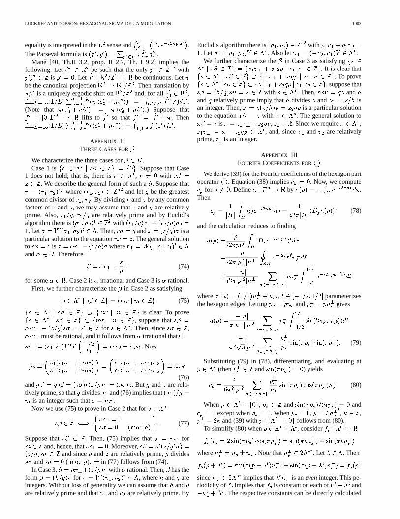
equality is interpreted in the sense and .The Parseval formula is .
Mane [40, Th.II 3.2, prop. II 2.7, Th. I 9.2] implies thefollowing. Let be such that the only with
is . Let be continuous. Letbe the canonical projection . Then translation by
is a uniquely ergodic shift on and, for all ,.
(Note that .) Suppose thatlifts to so that . Then
.
APPENDIX IITHREE CASES FOR
We characterize the three cases for .Case 1 is . Suppose that Case
1 does not hold; that is, there is , with. We describe the general form of such a. Suppose that
where and let be the greatestcommon divisor of , . By dividing and by any commonfactors of and , we may assume thatand are relativelyprime. Also, , are relatively prime and by Euclid’salgorithm there is with. Let . Then, and is a
particular solution to the equation . The general solutionto is whereand . Therefore
(74)
for some . Case 2 is irrational and Case 3 is rational.First, we further characterize thein Case 2 as satisfying
(75)
is clear. To prove, suppose that
for . Then, since ,must be rational, and it follows from irrational that
. Now
(76)and . But and are rela-tively prime, so that divides and (76) implies that
is an integer such that .Now we use (75) to prove in Case 2 that for
(77)
Suppose that . Then, (75) implies that forand, hence, that . Moreover,
and since and are relatively prime, dividesand ( ). in (77) follows from (74).
In Case 3, with rational. Then, has theform for , where and areintegers. Without loss of generality we can assume thatandare relatively prime and that and are relatively prime. By
Euclid’s algorithm there is with. Let . Also let .We further characterize the in Case 3 as satisfying
. It is clear that. To prove
, suppose thatwith . Then, and
and relatively prime imply that divides and isan integer. Then, is a particular solutionto the equation with . The general solution to
is , . Since we require ,, and, since and are relatively
prime, is an integer.
APPENDIX IIIFOURIER COEFFICIENTS FOR
We derive (39) for the Fourier coefficients of the hexagon partoperator . Equation (38) implies . Now, we compute
for . Define by .Then
(78)
and the calculation reduces to finding
where , parameterizesthe hexagon edges. Letting and gives
(79)
Substituting (79) in (78), differentiating, and evaluating at(then and ) yields
(80)
When , and andexcept when . When , , ,
and (39) with follows from (80).To simplify (80) when , consider
where . Note that . Let . Then
since implies that is aneveninteger. This pe-riodicity of implies that is constant on each of and
. The respective constants can be directly calculated

1004 IEEE TRANSACTIONS ON CIRCUITS AND SYSTEMS—I: FUNDAMENTAL THEORY AND APPLICATIONS, VOL. 50, NO. 8, AUGUST 2003
as for . Thenand, for
Using we obtain (39) for .
APPENDIX IVABSOLUTE SUMMABILITY
We prove that the coefficents .For the case , .
Using where
For the case , the sum is overpoints in three lines and .Using where
REFERENCES
[1] J. C. Candy and G. C. Temes, Eds.,Oversampling Methods for A/D andD/A Conversion. Piscataway, NJ: IEEE Press, 1992.
[2] S. R. Norsworthy, R. Schreier, and G. C. Temes, Eds.,Delta- Sigma DataConverters: Theory, Design, and Simulation. Piscataway, NJ: IEEEPress, 1997.
[3] J. C. Candy and O. J. Benjamin, “The structure of quantization noisefrom sigma-delta modulation,”IEEE Trans. Commun., vol. COM-29,pp. 1316–1323, Sept. 1981.
[4] J. C. Candy, “A use of double integration in sigma delta modulation,”IEEE Trans. Commun., vol. COM-33, no. 3, pp. 249–258, Mar. 1985.
[5] G. Luckjiff, I. Dobson, and D. Divan, “Interpolative sigma-delta modu-lators for high frequency power-electronic applications,” inProc. PowerElectronics Specialists Conf., Atlanta, GA, June 1995, pp. 444–449.
[6] T. G. Habetler and D. M. Divan, “Performance characterization of a newdiscrete pulse modulated current regulator,” inProc. Ind. Appl. Soc.,Pittsburgh, PA, Oct. 1988, pp. 395–405.
[7] D. M. Divan, “The resonant dc link converter,” inProc. Ind. Appl. Soc.,Denver, CO, 1986, pp. 648–656.
[8] H. Van Der Broeck, H. Skudelny, and G. Stanke, “Analysis and realiza-tion of a pulsewidth modulator based on voltage space vectors,”IEEETrans. Ind. Applicat., vol. 24, pp. 142–150, Feb. 1988.
[9] J. H. Conway and N. J. A. Sloane,Sphere Packings, Lattices and Groups,2nd ed. New York: Springer-Verlag, 1993.
[10] A. Gersho, “On the structure of vector quantizers,”IEEE Trans. Inform.Theory, vol. IT-28, pp. 157–166, Mar. 1982.
[11] A. Gersho and R. M. Gray,Vector Quantization and Signal Compres-sion. Boston, MA: Kluwer, 1992.
[12] W. R. Bennett, “Spectra of quantized signals,”Bell Syst. Tech. J., vol.27, pp. 446–472, 1948.
[13] R. Schreier, “An empirical study of high order single bit delta sigmamodulators,”IEEE Trans. Circuits Syst., vol. 40, pp. 461–466, Aug.1993.
[14] R. M. Gray, “Spectral analysis of quantization noise in a single- loopsigma-delta modulator with dc input,”IEEE Trans. Commun., vol. 37,pp. 588–599, June 1989.
[15] , “Oversampled sigma-delta modulation,”IEEE Trans. Commun.,vol. COM-35, pp. 481–488, July 1987.
[16] , “Quantization noise spectra,”IEEE Trans. Inform. Theory, vol.36, pp. 1220–1244, Nov. 1990.
[17] D. F. Delchamps, “Exact asymptotic statistics for sigma-delta quantiza-tion noise,” inProc. Allerton Conf. Communication, Control, and Com-puting, Urbana, IL, Oct. 1990, pp. 703–712.
[18] , “Spectral analysis of sigma-delta quantization noise,” inProc.Information Sciences and Systems, Baltimore, MD, Mar. 1990, pp.167–172.
[19] N. He, F. Kuhlmann, and A. Buzo, “Double-loop sigma-delta modula-tion with dc input,”IEEE Trans. Commun., vol. COM- 38, pp. 106–114,Apr. 1990.
[20] J. C. Kieffer, “Analysis of dc input response for a class of one-bit feed-back encoders,”IEEE Trans. Commun., vol. COM-38, pp. 337–340,Mar. 1990.
[21] S. Hein and A. Zakhor, “On the stability of sigma-delta modulators,”IEEE Trans. Signal Processing, vol. 41, pp. 2322–2348, July 1993.
[22] H. Wang, “�� modulation from the perspective of nonlinear dy-namics,” inProc. ISCAS’92, vol. 3, May 1992, pp. 1296–1299.
[23] O. Feely, D. Fournier-Prunaret, I. Taralova-Roux, and D. Fitzgerald,“Nonlinear dynamics of bandpass sigma-delta modulation – An inves-tigation by means of the critical lines tool,”Int. J. Bifurcations Chaos,vol. 10, no. 2, pp. 307–323, 2000.
[24] G. Luckjiff and I. Dobson, “Power spectrum of a sigma-delta modu-lator with hexagonal vector quantization and constant input,” inProc.Int. Symp. Circuits and Systems, vol. 5, Orlando, FL, May 1999, pp.270–273.
[25] A. Boehringer and F. Brugger, “Transformatorlose transistor- pulsum-richter mit ausgangsleistungen bis 50 kva,”Elektr. Masch., vol. 96, no.12, pp. 538–545, 1979.
[26] B. Schwarz, “Beiträge zu Reaktionsschnellen und Hochge NauenDrehstrom-Positionier-Systemen,” Ph.D. dissertation, Univ. Stuttgart,Stuttgart, Germany, 1986.
[27] M. Kheraluwala and D. M. Divan, “Delta modulation strategies forresonant link inverters,” inProc. Power Electronics Specialists Conf.,Blacksburg, VA, June 1987, pp. 271–278.
[28] D. R. Seidl, “Motion and Motor Control Using Structured Neural Net-works,” Ph.D. dissertation, Dep. Elect. Comp. Eng., University of Wis-consin-Madison, Madison, WI, 1996.
[29] G. Venkataramanan, D. M. Divan, and T. M. Jahns, “Discrete pulse mod-ulation strategies for high-frequency inverter systems,” inProc. PowerElectronics Specialists Conf., vol. 2, Milwaukee, WI, June 1989, pp.1013–1020.
[30] A. Mertens, “Performance analysis of three-phase inverters controlledby synchronous delta-modulation systems,”IEEE Trans. Ind. Applicat.,vol. 30, pp. 1016–1027, Aug. 1994.
[31] J. P. Vilain and C. Lesbroussart, “A new space vector modulationstrategy for a three-phase inverter: The space vector based delta-sigmamodulation,”J. Phys. III, vol. 5, no. 7, pp. 1075–1088, 1995.
[32] G. Venkataramanan, “Topology, Analysis and Control of a Resonantdc Link Power Converter,” Ph.D. dissertation, Dep. Elect. Comp. Eng.,University of Wisconsin-Madison, Madison, WI, 1992.
[33] A. Mertens and H. Skudelny, “Calculations on the spectral performanceof discrete pulse modulation strategies,” inProc. Power Electronics Spe-cialists Conf., Boston, MA, June 1991, pp. 357–365.
[34] J. Nieznanski, “Performance characterization of vector sigma- deltamodulation,” inProc. Ind. Elect. Soc. Conf., vol. 1, Aachen, Germany,Aug–Sept. 1998, pp. 531–536.
[35] G. Luckjiff, I. Dobson, and D. M. Divan, “Modulator for Resonant LinkConverters,” U.S. Patent no. 5 619 406, Apr. 8 1997.
[36] H. Furstenberg,Recurrence in Ergodic Theory and CombinationalNumber Theory. Princeton, NJ: Princeton Univ. Press, 1981.
[37] C. Corduneanu,Almost Periodic Functions. New York: Wiley, 1968.[38] Y. Katznelson,An Introduction to Harmonic Analysis, 2nd ed. New
York: Dover, 1976.[39] W. Rudin,Fourier Analysis on Groups. New York: Wiley, 1962.[40] R. Mãné,Ergodic Theory and Differentiable Dynamics. New York:
Springer-Verlag, 1987.[41] A. Zygmund,Trigonometric Series, 2nd ed. Cambridge, U.K.: Cam-
bridge Univ. Press, 1959.

LUCKJIFF AND DOBSON: HEXAGONAL SIGMA-DELTA MODULATION 1005
Glen Luckjiff received the B.S., M.S., and Ph.D.degrees from the Lafayette College, Easton, PA, theRensselaer Polytechnic Institute, Troy, NY, and theUniversity of Wisconsin, Madison, in 1989, 1991,and 2002, respectively, in electrical engineering, andthe M.S. degree in financial mathematics from theUniversity of Chicago, Chicago, IL, in 2003.
In 1991, he was with GE Corporate Researchand Development, Schenectady, NY, and since1995, has been with Soft Switching TechnologiesCorporation, Madison, WI. His research interests
include sigma–delta modulation and the control of power-electronic systems.
Ian Dobson (M’89–SM’98) received the B.A. de-gree in math from Cambridge University, Cambridge,U.K., in 1978, and the Ph.D. degree in electrical en-gineering from Cornell University, Ithaca, NY, 1989.
He was a Systems Analyst for EASAMS Ltd,Frimley, U.K., from 1978 to 1983. In 1989, hejoined the University of Wisconsin-Madison, wherehe is now a Professor in Electrical and ComputerEngineering. His current interests are applicationsof complex systems, nonlinear dynamics, electricpower system instabilities, power electronics, and
self-organized criticality.


![Switching Time Bifurcations in a Thyristor …iandobson.ece.iastate.edu/PAPERS/jalaliCAS96.pdfthyristor controlled reactor circuit such as its novel transient dynamics [22] and analyzing](https://img.dokumen.tips/doc/110x75/5f33b0b189baee5732089958/switching-time-bifurcations-in-a-thyristor-thyristor-controlled-reactor-circuit.jpg)