Embed Size (px)
Citation preview

Heterogeneous Concurrent Modeling and Design inJava (Volume 1: Introduction to Ptolemy II)
Christopher BrooksEdward A. LeeXiaojun LiuStephen NeuendorfferYang ZhaoHaiyang Zheng
Electrical Engineering and Computer SciencesUniversity of California at Berkeley
Technical Report No. UCB/EECS-2007-7
http://www.eecs.berkeley.edu/Pubs/TechRpts/2007/EECS-2007-7.html
January 11, 2007

Copyright © 2007, by the author(s).All rights reserved.
Permission to make digital or hard copies of all or part of this work forpersonal or classroom use is granted without fee provided that copies arenot made or distributed for profit or commercial advantage and that copiesbear this notice and the full citation on the first page. To copy otherwise, torepublish, to post on servers or to redistribute to lists, requires prior specificpermission.
Acknowledgement
This work was supported in part by the Center for Hybrid and EmbeddedSoftware Systems (CHESS) at UC Berkeley, which receives supportfrom the National Science Foundation (NSF award #CCR-0225610), theState of California Micro Program, Rome AFRL, and the followingcompanies:Agilent, DGIST, General Motors, Hewlett Packard, Infineon,Microsoft, National Instruments, and Toyota.

PTOLEMY IIHETEROGENEOUS
CONCURRENT MODELING AND DESIGN IN JAVA
Edited by:Christopher Brooks, Edward A. Lee, Xiaojun Liu, Steve Neuendorffer, Yang Zhao, Haiyang Zheng
VOLUME 1: INTRODUCTION TO PTOLEMY II
Authors:Shuvra S. BhattacharyyaChristopher BrooksElaine CheongJohn Davis, IIMudit GoelBart KienhuisEdward A. LeeMan-Kit LeungJie LiuXiaojun LiuLukito MuliadiSteve NeuendorfferJohn ReekieNeil SmythJeff TsayBrian VogelWinthrop WilliamsYuhong XiongYang ZhaoHaiyang ZhengGang Zhou
Department of Electrical Engineering and Computer SciencesUniversity of California at Berkeleyhttp://ptolemy.eecs.berkeley.edu
Document Version 6.0for use with Ptolemy II 6.0January 11, 2007
Earlier versions:• UCB/ERL M05/21, UCB/ERL M04/27, UCB/ERL M03/27,
UCB/ERL M02/23, UCB/ERL M01/12, UCB/ERL M99/40
This work was supported in part by the Center for Hybrid and Embed-ded Software Systems (CHESS) at UC Berkeley, which receives support from the National Science Foundation (NSF award #CCR-0225610), the State of California Micro Program, Rome AFRL, and the following com-panies: Agilent, DGIST, General Motors, Hewlett Packard, Infineon, Microsoft, National Instruments, and Toyota.
A
•T
HE
•UN
IVE
RS I T Y • O F • C
AL
I FO
RN
IA•
•1868•
LET THE R E BE
LIG H T


Copyright © 1998-2007 The Regents of the University of California.All rights reserved.
“Java” is a registered trademark of Sun Microsystems.

VOLUME 1
INTRODUCTION TO PTOLEMY II
This volume describes how to construct Ptolemy II models for web-based modeling or building appli-cations. The first chapter includes an overview of Ptolemy II software, and a brief description of eachof the models of computation that have been implemented. It describes the package structure of thesoftware, and includes as an appendix a brief tutorial on UML notation, which is used throughout thedocumentation to explain the structure of the software. The second chapter is a tutorial on buildingmodels using Vergil, a graphical user interface where models are built pictorially. The third chapterdiscusses the Ptolemy II expression language, which is used to set parameter values. The next chaptergives an overview of actor libraries. These three chapters, plus one of the domain chapters, will be suf-ficient for users to start building interesting models in the selected domain. The fifth chapter gives atutorial on designing actors in Java. The sixth chapter describes the Ptolemy coding style, The seventhchapter explains MoML, the XML schema used by Vergil to store models. And the eighth chapter, thefinal one in this part, explains how to construct custom applets.
Volume 2 describes the software architecture of Ptolemy II, and volume 3 describes the domains, eachof which implements a model of computation.

This page intentionally left mostly blank.


Contents
Volume 1
Introduction to Ptolemy II 3Contents 5
1. Introduction 11.1. Purpose 1
1.1.1. Gabriel (1986-1991) 21.1.2. Ptolemy Classic (1990-1997) 21.1.3. Ptolemy II (1996-?) 21.1.4. Organization of this Document 4
1.2. Modeling and Design 41.2.1. Embedded Software 51.2.2. Actor-Oriented Design 61.2.3. Actor-Oriented Classes, Subclasses, and Inheritance 81.2.4. Syntaxes 101.2.5. Architecture Design 13
1.3. Models of Computation 141.3.1. Component Interaction - CI 151.3.2. Continuous Time - CT 151.3.3. Discrete-Events - DE 161.3.4. Distributed Discrete Events - DDE 161.3.5. Dynamic Data Flow - DDF 171.3.6. Discrete Time - DT 171.3.7. Finite-State Machines - FSM 171.3.8. Giotto 181.3.9. Graphics - GR 181.3.10. Heterochronous Dataflow 181.3.11. Hybrid Systems 181.3.12. Process Networks - PN 191.3.13. Rendezvous 221.3.14. Synchronous Dataflow - SDF 221.3.15. Synchronous/Reactive - SR 221.3.16. Timed Multitasking - TM 231.3.17. Wireless 23
1.4. Choosing Models of Computation 251.5. Ptolemy II Architecture 25
1.5.1. Core Packages 261.5.2. Overview of Key Classes 301.5.3. Domains 321.5.4. Library Packages 33

1.5.5. User Interface Packages 351.5.6. Capabilities 351.5.7. Experimental Capabilities 391.5.8. Future Capabilities 39
1.6. Acknowledgements 40Appendix: UML — Unified Modeling Language 42
Package Diagrams 42Static Structure Diagrams 42
Appendix: Ptolemy II Naming Conventions 45Classes 45Members 45Methods 45
2. Using Vergil 472.1. Introduction 472.2. Quick Start 47
2.2.1. Starting Vergil 472.2.2. Executing a Pre-Built Model: A Signal Processing Example 492.2.3. Executing a Pre-Built Model: A Continuous-Time Example 502.2.4. Creating a New Model 542.2.5. Running the Model 552.2.6. Making Connections 56
2.3. Tokens and Data Types 582.4. Hierarchy 61
2.4.1. Creating a Composite Actor 612.4.2. Adding Ports to a Composite Actor 612.4.3. Setting the Types of Ports 63
2.5. Annotations and Parameterization 642.5.1. Parameters in Hierarchical Models 642.5.2. Decorative Elements 662.5.3. Creating Custom Icons 66
2.6. Navigating Larger Models 662.7. Classes and Inheritance 68
2.7.1. Creating and Using Actor-Oriented Classes 682.7.2. Overriding Parameter Values in Instances 702.7.3. Subclassing and Inheritance 712.7.4. Sharing Classes Across Models 73
2.8. Higher-Order Components 752.8.1. MultiInstance Composite 762.8.2. IterateOverArray 782.8.3. Mobile Code 792.8.4. Lifecycle Management Actors 79
2.9. Domains 792.9.1. SDF and Multirate Systems 802.9.2. Data-Dependent Rates 822.9.3. Discrete-Event Systems 822.9.4. Wireless and Sensor Network Systems 852.9.5. Continuous-Time Systems 85
2.10.Hybrid Systems and Modal Models 862.10.1. Examining a Pre-Built Model 862.10.2. Numerical Precision and Zeno Conditions 882.10.3. Constructing Modal Models 892.10.4. Execution Semantics 92
2.11.Using the Plotter 933. Expressions 97
3.1. Introduction 973.1.1. Expression Evaluator 97
3.2. Simple Arithmetic Expressions 983.2.1. Constants and Literals 983.2.2. Variables 1003.2.3. Operators 1003.2.4. Comments 102
3.3. Uses of Expressions 1023.3.1. Parameters 1023.3.2. Port Parameters 1033.3.3. String Parameters 1043.3.4. Expression Actor 1043.3.5. State Machines 105
3.4. Composite Data Types 1063.4.1. Arrays 1063.4.2. Matrices 1083.4.3. Records 110
3.5. Invoking Methods 1123.6. Defining Functions 1123.7. Built-In Functions 1153.8. Nil Tokens 1193.9. Fixed Point Numbers 1203.10.Units 121
Trigonometric Functions 124Basic Mathematical Functions 125Matrix, Array, and Record Functions. 127Functions for Evaluating Expressions 128Signal Processing Functions 129I/O Functions and Other Miscellaneous Functions 131
4. Actor Libraries 1334.1. Overview 1334.2. Actor Classes 1344.3. Actor Summaries 136
4.3.1. Sources 1364.3.2. Sinks 1394.3.3. Array 1414.3.4. Conversions 1424.3.5. Flow Control 1434.3.6. Higher Order Actors 1454.3.7. I/O 147

4.3.8. Logic 1474.3.9. Math 1484.3.10. Matrix 1494.3.11. Random 1494.3.12. Real Time 1504.3.13. Signal Processing 1504.3.14. String 1534.3.15. Domain Specific 1534.3.16. Discrete Event 1554.3.17. Process Networks 1564.3.18. Rendezvous 157
4.4. Data Polymorphism 1574.5. Domain Polymorphism 158
5. Designing Actors 1595.1. Overview 1595.2. Anatomy of an Actor 160
5.2.1. Ports 1605.2.2. Port Rates and Dependencies Between Ports 1655.2.3. Parameters 1675.2.4. Constructors 1685.2.5. Cloning 169
5.3. Action Methods 1705.3.1. Initialization 1715.3.2. Prefire 1715.3.3. Fire 1735.3.4. Postfire 1755.3.5. Wrapup 175
5.4. Coupled Port and Parameter 1775.5. Iterate Method 1795.6. Time 1805.7. Icons 180
5.7.1. The Older Method 180Appendix: Creating and Using a Simple Actor 182
6. Coding Style 1856.1. Motivation 1856.2. Anatomy of a File 186
6.2.1. Copyright 1866.2.2. Imports 189
6.3. Comment Structure 1906.3.1. Javadoc and HTML 1906.3.2. Class documentation 1906.3.3. Code rating 1916.3.4. Constructor documentation 1926.3.5. Method documentation 1926.3.6. Referring to methods in comments 1946.3.7. Tags in method documents 1956.3.8. FIXME annotations 195
6.4. Code Structure 1956.4.1. Names of classes and variables 1956.4.2. Indentation and brackets 1966.4.3. Spaces 1966.4.4. Exceptions 1976.4.5. Code Cleaning 197
6.5. Directory naming conventions 1987. MoML 199
7.1. Introduction 1997.2. MoML Principles 201
7.2.1. Clustered Graphs 2027.2.2. Relation Groups 2037.2.3. Abstraction 203
7.3. Specification of a Model 2047.3.1. Data Organization 2047.3.2. Overview of XML 2067.3.3. Names and Classes 2077.3.4. Top-Level Entities 2077.3.5. Entity Element 2087.3.6. Properties 2097.3.7. Doc Element 2117.3.8. Ports 2127.3.9. Relations and Links 2147.3.10. Classes 2167.3.11. Inheritance 2197.3.12. Directors 2197.3.13. Input Element 2207.3.14. Annotations for Visual Rendering 220
7.4. Incremental Parsing 2217.4.1. Adding Entities 2217.4.2. Using Absolute Names 2227.4.3. Adding Ports, Relations, and Links 2227.4.4. Changing Port Configurations 2227.4.5. Deleting Entities, Relations, and Ports 2237.4.6. Renaming Objects 2237.4.7. Converting a Class to an Entity or Vice Versa 2247.4.8. Changing Documentation, Properties, and Directors 2247.4.9. Removing Links 2247.4.10. Grouping Elements 225
7.5. Parsing MoML 2277.6. Exporting MoML 2287.7. Special Attributes 2297.8. Acknowledgements 230Appendix: Example 231
Sinewave Generator 231Modulation 235
8. Custom Applets 241

8.1. Introduction 2418.2. HTML Files Containing Applets 2428.3. Defining a Model in a Java File 243
8.3.1. A Model Class as a Composite Actor 2438.3.2. Compiling 2458.3.3. Executing the Model in an Application 2478.3.4. Extending PtolemyApplet 2488.3.5. Using Model Parameters 2488.3.6. Adding Custom Actors 2498.3.7. Using Jar Files 2518.3.8. Hints for Developing Applets 252
References 253Glossary 265Index 269

Heterogeneous Concurrent Modeling and Design 1
1 Introduction
Author: Edward A. LeeContributors: The entire Ptolemy team
1.1 Purpose
This document is the first of three volumes describing the Ptolemy II software. This first volumeintroduces the software and explains how to use it. The second volume documents the software archi-tecture and explains how to extend it. The third volume documents the “domains,” which realize mod-els of computation. Some of these are relatively mature and established, while some are highlyexperimental. Indeed, a major part of the Ptolemy Project is experimentation with models of computa-tion.
Ptolemy II is the current software infrastructure of the Ptolemy Project. For the participants in thePtolemy Project, Ptolemy II is first and foremost a laboratory for experimenting with design tech-niques. It is published freely and in open-source form for several reasons. First, the software comple-ments more traditional publication media, and serves as a clear, unambiguous, and completedescription of our research results. Second, the open architecture and open source encouragesresearchers to build their own methods, leveraging and extending the core infrastructure provided bythe software. This creates a community where much of the dialog is through the software. Third, thefreely available software encourages designers to try out the new design techniques that are introducedand give feedback to the Ptolemy Project. This helps guide further research. Fourth, the open sourcesoftware encourages commercial providers of software tools to commercialize the research results,which helps to maximize the impact of the work.
The Ptolemy Project is an informal group of researchers at U.C. Berkeley. There have been manyparticipants in the project over the years (see “Acknowledgements” on page 40 for a list of contribu-tors to Ptolemy II). Ptolemy II is the third generation of design software to emerge from this group,with each generation addressing a new set of problems, with new emphasis, and (largely) a new groupof contributors.

2 Ptolemy II
Introduction
1.1.1 Gabriel (1986-1991)
The first generation of software created by this group was called Gabriel [19]. It was written inLisp and aimed at signal processing. It was during the construction of Gabriel that synchronous data-flow (SDF) block diagrams and both sequential and parallel scheduling techniques for SDF modelsmatured. Gabriel included code generators for programmable DSPs that produced efficient assemblycode for certain processors (notably, Motorola processors). Gabriel included hardware/software co-simulators, where parallel code generators would produce assembly code which then ran on instructionset simulators within a hardware simulation of a multiprocessor architecture. Gabriel had a graphicaluser interface built on top of Vem, written by Rick Spickelmeyer, which was originally designed forschematic capture in VLSI CAD. It used Oct, which was the design database developed by the Berke-ley CAD group under the leadership of Professor Richard Newton.
1.1.2 Ptolemy Classic (1990-1997)
Ptolemy Classic, started jointly by Professors Edward Lee and Dave Messerschmitt in 1990, waswritten in C++ [23]. It was the first modeling environment to systematically support multiple modelsof computation, hierarchically combined. We ported the SDF capabilities from Gabriel, and also devel-oped boolean dataflow (BDF), dynamic dataflow (DDF), multidimensional synchronous dataflow(MDSDF) and process networks (PN) domains. We also ported the DSP code generators, and createdC and VHDL code generators as well. We developed the concept of “targets,” which encapsulatedknowledge about specific hardware platforms, and demonstrated construction of models that executedon attached embedded processors (such as S-bus cards with DSPs), including models that executedjointly on a Unix host and the attached embedded processor. We developed a discrete-event domainand demonstrated joint modeling of communication networks and signal processing, and also devel-oped a hardware simulation domain called Thor, which was adapted from an open-source hardwaresimulator by the same name (see figure 1.1). We made major contributions to SDF scheduling tech-niques, including introducing the concept of “single appearance schedules” (which minimize gener-ated code size and enable extensive use of inlining of generated code). We also introduced “higher-order components,” which greatly increased the expressiveness of visual syntaxes. The Ptolemy Clas-sic user interface was an extension of the Gabriel interface, still based on Oct and Vem, but extendedby Tycho (written in Itcl, an object-oriented extension of Tcl/Tk). Portions of Ptolemy Classic werecommercialized as part of the Agilent ADS system, and methods from Ptolemy Classic were used inCadence’s SPW system.
1.1.3 Ptolemy II (1996-?)
The Ptolemy Project (as it was now known) began working on Ptolemy II in 1996. The major rea-sons for starting over were to exploit the network integration, code migration, built-in threading, anduser-interface capabilities of Java. Ptolemy II introduced the notion of domain polymorphism (wherecomponents could be designed to be able to operate in multiple domains) and modal models (wherefinite state machines are combined hierarchically with other models of computation). We built a con-tinuous-time domain, that when combined with the modal modeling capability, yields hybrid systemmodeling. Ptolemy II has a sophisticated type system with type inference and data polymorphism(where components can be designed to operate on multiple data types), and a rich expression language.The concept of behavioral types emerged (where components and domains could have interface defini-tions that describe not just static structure, as with traditional type systems, but also dynamic behav-ior). Some (but not all) of the SDF capabilities from Ptolemy Classic were ported, and the

Heterogeneous Concurrent Modeling and Design 3
Introduction
heterochronous dataflow model was introduced. We contributed to a user-interface toolkit (calledDiva) based on Java, built a user interface for Ptolemy II (called Vergil) based on Diva, designed aJava plotter (PtPlot), and introduced a 3-D animation domain. We built models that could be used asapplets in a web browser. We introduced actor-oriented classes and subclasses with inheritance, andwe added modeling capabilities for wireless systems. We also introduced lifecycle management actorsand dynamically evaluated higher-order components. And we built numerous experimental domainsthat explored real-time and distributed computing (distributed discrete events (DDE), timed multitask-ing (TM), Giotto, and component interaction (CI)). As for code generation, the tactic in Ptolemy IIembodies two approaches, both significantly different than that in Gabriel or Ptolemy Classic. In thefirst approach, developed by Steve Neuendorffer, instead of components as generators, the code gener-ator called Copernicus uses a component-specialization framework built on top of a Java compilertoolkit called Soot. The second approach has components as generators, but uses an architecture wherethe interfaces of components are defined exactly as in ordinary Ptolemy II actors, and “helpers” are
FIGURE 1.1. Ptolemy Classic screen image (from 1993) showing an SDF graph at the upper left that is auto-matically mapped and scheduled onto the two processor architecture, whose model is at the lower right (in the “Thor” domain). Assembly code for the two processors is generated, and then ISA simulators of the pro-cessors (provided by Motorola, lower left) interact with the Thor-domain simulation, resulting in the logic analyzer trace at the upper right.

4 Ptolemy II
Introduction
used to generate code for particular targets. Also new to Ptolemy II is the use of XML for its persistent data representation. It has also intro-
duced the concept of migrating models. It further provides an infrastructure for creating specialized“configurations,” which are packaged subsets of the Ptolemy II software together with customizeddocumentation and interfaces. HyVisual, VisualSense, and Kepler are examples of separate softwareapplications that are built as Ptolemy II configurations.
1.1.4 Organization of this Document
This document is the first of three volumes. This first volume introduces the software and explainshow to use it. It begins with a description of the rationale for the design in this chapter. The secondchapter is a tutorial that explains how to use Ptolemy II via the Vergil visual editor. The third chapterexplains the expression language, which is used extensively in Ptolemy II. The fourth chapter providesan overview of the actor libraries; note, however, that the most complete documentation for the actorsis built in to the software, accessed through the “Get Documentation” command, obtained by rightclicking on the actor icon. The fifth chapter explains how to write actors. The sixth chapter describesMoML, the XML schema used to store Ptolemy II models.
A great deal more information, including many published papers, can be found on the PtolemyProject website, http://ptolemy.org. In addition, extensive documentation is available on-line whenrunning Vergil. Right clicking on most objects will offer a “Get Documentation” choice.
1.2 Modeling and Design
The Ptolemy project studies heterogeneous modeling, simulation, and design of concurrent sys-tems. A major focus is on embedded systems [84], particularly those that mix technologies including,for example, analog and digital electronics, hardware and software, and electronics and mechanicaldevices. Another major focus is on systems that are complex in the sense that they mix widely differentoperations, such as networking, signal processing, feedback control, mode changes, sequential deci-sion making, and user interfaces.
Modeling is the act of representing a system or subsystem formally. A model might be mathemati-cal, in which case it can be viewed as a set of assertions about properties of the system such as its func-tionality or physical dimensions. A model can also be constructive, in which case it defines acomputational procedure that mimics a set of properties of the system. Constructive models are oftenused to describe behavior of a system in response to stimulus from outside the system. Constructivemodels are also called executable models.
Design is the act of defining a system or subsystem. Usually this involves defining one or moremodels of the system and refining the models until the desired functionality is obtained within a set ofconstraints.
Design and modeling are obviously closely coupled. In some circumstances, models may beimmutable, in the sense that they describe subsystems, constraints, or behaviors that are externallyimposed on a design. For instance, they may describe a mechanical system that is not under design, butmust be controlled by an electronic system that is under design.
Executable models are sometimes called simulations, an appropriate term when the executablemodel is clearly distinct from the system it models. However, in many electronic systems, a model thatstarts as a simulation mutates into a software implementation of the system. The distinction betweenthe model and the system itself becomes blurred in this case. This is particularly true for embedded

Heterogeneous Concurrent Modeling and Design 5
Introduction
software.
1.2.1 Embedded Software
Embedded software is software that resides in devices that are not first-and-foremost computers. Itis pervasive, appearing in automobiles, telephones, pagers, consumer electronics, toys, aircraft, trains,security systems, weapons systems, printers, modems, copiers, thermostats, manufacturing systems,appliances, etc. A technically active person probably interacts regularly with more pieces of embeddedsoftware than conventional software. A key feature of embedded software is that it engages the physi-cal world, and hence has temporal constraints that desktop software does not share.
A major emphasis in Ptolemy II is on the methodology for defining and producingembedded software together with the systems within which it is embedded.
Executable models are constructed under a model of computation, which is the set of “laws ofphysics” that govern the interaction of components in the model. If the model is describing a mechani-cal system, then the model of computation may literally be the laws of physics. More commonly, how-ever, it is a set of rules that are more abstract, and provide a framework within which a designer buildsmodels. A set of rules that govern the interaction of components is called the semantics of the model ofcomputation. A model of computation may have more than one semantics, in that there might be dis-tinct sets of rules that impose identical constraints on behavior.
The choice of model of computation depends strongly on the type of model being constructed. Forexample, for a purely computational system that transforms a finite body of data into another finitebody of data, the imperative semantics that is common in programming languages such as C, C++,Java, and MATLAB will be adequate. For modeling a mechanical system, the semantics needs to beable to handle concurrency and the time continuum, in which case a continuous-time model of compu-tation such as that found in Simulink, Saber, Hewlett-Packard’s ADS, and VHDL-AMS is more appro-priate.
The ability of a model to mutate into an implementation depends heavily on the model of compu-tation that is used. Some models of computation, for example, are suitable for implementation only incustomized hardware, while others are poorly matched to customized hardware because of their intrin-sically sequential nature. Choosing an inappropriate model of computation may compromise the qual-ity of design by leading the designer into a more costly or less reliable implementation.
A principle of the Ptolemy project is that the choices of models of computationstrongly affect the quality of a system design.
For embedded systems, the most useful models of computation handle concurrency and time. Thisis because embedded systems consist typically of components that operate simultaneously and havemultiple simultaneous sources of stimuli. In addition, they operate in a timed (real world) environment,where the timeliness of their response to stimuli may be as important as the correctness of theresponse.
The objective in Ptolemy II is to support the construction and interoperability ofexecutable models that are built under a wide variety of models of computation.
Ptolemy II takes a component view of design, in that models are constructed as a set of interactingcomponents. A model of computation governs the semantics of the interaction, and thus imposes a dis-

6 Ptolemy II
Introduction
cipline on the interaction of components.
Component-based design in Ptolemy II involves disciplined interactions betweencomponents governed by a model of computation.
1.2.2 Actor-Oriented Design
Most (but not all) models of computation in Ptolemy II support actor-oriented design. This con-trasts with (and complements) object-oriented design by emphasizing concurrency and communicationbetween components. Components called actors execute and communicate with other actors in amodel, as illustrated in figure 1.2. Like objects, actors have a well defined component interface. Thisinterface abstracts the internal state and behavior of an actor, and restricts how an actor interacts withits environment. The interface includes ports that represent points of communication for an actor, andparameters that are used to configure the operation of an actor. Often, parameter values are part of thea priori configuration of an actor and do not change when a model is executed, but not always. The“port/parameters” shown in figure 1.2 function as both ports and parameters.
Central to actor-oriented design are the communication channels that pass data from one port toanother according to some messaging scheme. Whereas with object-oriented design, componentsinteract primarily by transferring control through method calls, in actor-oriented design, they interactby sending messages through channels. The use of channels to mediate communication implies thatactors interact only with the channels that they are connected to and not directly with other actors.
Like actors, a model may also define an external interface; this interface is called its hierarchicalabstraction. This interface consists of external ports and external parameters, which are distinct fromthe ports and parameters of the individual actors in the model. The external ports of a model can be
port/parameters
hierarchical abstraction
model
director
annotation
actorport
relation
external port
FIGURE 1.2. Illustration of an actor-oriented model (above) and its hierarchical abstraction (below).
link to documentation

Heterogeneous Concurrent Modeling and Design 7
Introduction
connected by channels to other external ports of the model or to the ports of actors that compose themodel. External parameters of a model can be used to determine the values of the parameters of actorsinside the model.
Taken together, the concepts of models, actors, ports, parameters and channels describe theabstract syntax of actor-oriented design. The abstract syntax gives the structure of models without say-ing anything about how they operate. This syntax can be represented concretely in several ways, suchas graphically, as in figure 4, in XML as in figure 1.3, or in a program designed to a specific API (as inSystemC). Ptolemy II offers all three alternatives.
It is important to realize that the syntactic structure of an actor-oriented design says little about thesemantics. The semantics is largely orthogonal to the syntax, and is determined by a model of compu-tation. The model of computation might give operational rules for executing a model. These rulesdetermine when actors perform internal computation, update their internal state, and perform externalcommunication. The model of computation also defines the nature of communication between compo-nents.
Our notion of actor-oriented modeling is related to the work of Gul Agha and others. The termactor was introduced in the 1970’s by Carl Hewitt of MIT to describe the concept of autonomous rea-soning agents [59]. The term evolved through the work of Agha and others to describe a formalizedmodel of concurrency [1-5]. Agha’s actors each have an independent thread of control and communi-cate via asynchronous message passing. We have further developed the term to embrace a larger familyof models of concurrency that are often more constrained than general message passing. Our actors arestill conceptually concurrent, but unlike Agha’s actors, they need not have their own thread of control.Moreover, although communication is still through some form of message passing, it need not bestrictly asynchronous.
Actor-oriented modeling has been around for some time, and is in widespread use through suchprograms as Simulink, from The Mathworks, LabVIEW, from National Instruments, and many others.It is gaining broader legitimacy through the efforts of OMG in UML-2 [123], for example, some ofwhich has its roots in the actor-oriented framework ROOM [139]. Many research projects are based onsome form of actor-oriented modeling, but the Ptolemy Project is unique in the breadth of exploration
<class name="Sinewave"><property name="samplingFrequency" value="8000.0"/><property name="frequency" value="440.0"/><property name="phase" value="0.0"/><property name="SDF Director" class="ptolemy.domains.sdf.kernel.SDFDirector"/><port name="output"><property name="output"/><entity name="Ramp" class="ptolemy.actor.lib.Ramp">
<property name="init" value="phase"/><property name="step" value="frequency*2*PI/samplingFrequency"/>
</entity><entity name="TrigFunction" class="ptolemy.actor.lib.TrigFunction">
<property name="function" value="sin" class="ptolemy.kernel.util.StringAttribute"/></entity><relation name="relation"/><relation name="relation2"/><link port="output" relation="relation2"/><link port="Ramp.output" relation="relation"/><link port="TrigFunction.input" relation="relation"/><link port="TrigFunction.output" relation="relation2"/>
</class>
FIGURE 1.3. An XML representation of a simplified sinewave source.

8 Ptolemy II
Introduction
of semantic alternatives and in the commitment made to a particular model of computation within adomain. Because domains can be mixed hierarchically, each domain can be made more specializedwithout compromising its utility.
Perhaps the earliest actor-oriented programming language was created by William (Bert) Suther-land on a TX-2 computer at MIT Lincoln Labs [142]. Sutherland’s system had a visual syntax, where aprogrammer would use a light pen to create diagrams representing programs. His system was built ontop one of the first acknowledged object-oriented programming systems, Sketchpad, created by hisbrother Ivan Sutherland [141].
1.2.3 Actor-Oriented Classes, Subclasses, and Inheritance
Starting with version 4.0 of Ptolemy II, we have extended actor-oriented design techniques withmodularity mechanisms analogous to those found in object-oriented languages [79]. Consider a simpleexample, shown in figure 1.4. The model at the lower left is the same sine wave generator as in figure1.2. In figure 1.2, the block labeled “Sinewave” at the bottom actually represents an instance of a class,where the definition of the class is given by the block diagram at the top of figure 1.2. In figure 1.4,that class definition is extended to create a new subclass definition called “NoisySinewave,” whosedefinition is shown at the bottom right of the figure. That subclass “inherits” components (actors) andconnections from the base class. The inherited components are outlined with a dashed outline. It thenoverrides the definition by adding a second output port, two more override actors and connectionsbetween these. These additions have no dashed outline.
The NoisySinewave class definition is local to the model at the upper left of figure 1.4. That is, theclass definition is part of the model definition and is available for instantiation and subclassing onlywithin this model. The class definition is shown visually by an icon that is outlined in light blue to dis-tinguish it visually from an instance. This contrasts with the Sinewave class definition, which isdefined in its own model file, and is accessible to any model that wishes to use it. Thus, Ptolemy IIprovides levels of visibility and well-defined scoping for class definitions. Moreover, class definitionscan themselves contain class definitions, so Ptolemy II provides “inner classes” of a sort.
A class that is defined in its own file is called a top-level class. Any model can instantiate or sub-class a top-level class if the file defining the class is in the classpath. A class that is a component in amodel and is available for instantiation or subclassing is called a local class. The Sinewave class in fig-ure 1.4 is a top-level class, while NoisySinewave is a local class. When a class is defined within amodel, its definition is in scope at the same level of the hierarchy where it is defined and at all levelsbelow that1. Thus, for example, the model at the upper left in figure 1.4 contains both the class defini-tion NoisySinewave and the instance InstanceOfNoisySinewave.
The model in figure 1.4, when executed, produces two signal traces, as shown in the plot at theupper right. One is a simple sine wave and the other is a noisy sine wave. The simple sine wave is gen-erated by the Sinewave actor, which is an instance of the Sinewave class (defined in a separate file),and the noisy sine wave is generated by the InstanceOfNoisySinewave actor, which is an instance ofNoisySinewave, a subclass of Sinewave.
In building this mechanism into Ptolemy II, we had to make a number of decisions that amount tolanguage design decisions. First, in Ptolemy II, a model is a set of actors, ports, attributes, and connec-tions. A model can be viewed as a program with (optionally) a visual syntax. Each of the three gray
1. This is the same scoping rule that applies to attributes in the Ptolemy II expression language, described in a sub-sequent chapter.

Heterogeneous Concurrent Modeling and Design 9
Introduction
boxes containing actors, connections, and annotations in figure 1.4 is a model. In Ptolemy II, anymodel can be either a class or an instance. A class serves as a prototype for instances. Our mechanism,therefore, is closely related to prototype-based languages (see chapter 3 of [32], for example), but witha twist. In order to ensure that the class mechanism operates entirely at the abstract syntax level,classes in Ptolemy II are purely syntactic objects and play no role in the execution of a model. They arenot visible to the director, which provides the execution engine. As consequence, Ptolemy II does notpermit the ports of a class definition to be connected to other ports, and any attempt to connect the boxlabeled NoisySinewave in figure 1.4 will trigger an error.
A subclass inherits the structure of its base class. Specifically, every object (actor, attribute, port orconnection) contained by the base class has a corresponding object in the subclass. We refer to this asthe derivation invariant. The pink dashed outlines in figure 1.4 surround such “corresponding objects.”They provide a visual indication that those objects cannot be removed, since doing so would violate
execution result
local class definition
override
FIGURE 1.4. Illustration of actor-oriented classes, subclasses, and inheritance.
instance
subclass
instance
inheritedactors
actors
top-level class definition

10 Ptolemy II
Introduction
the derivation invariant. However, the subclass can contain new objects and can also change (override)the values of attributes that carry values (we generally refer to attributes that carry values as parame-ters).
Since a model can contain class definitions, and a model can itself be a class definition, we haveinner classes. This is a significant departure from the prototype mechanism given in [68], where it is(correctly) pointed out that such inner classes create significant complications. In particular, they cre-ate a specialized form of multiple inheritance. Although this is a significant complication, we believethat it is sufficiently disciplined, modular, and expressive to be justified. The underlying formalism isgiven in [79].
A number of related experiments in this direction have also been performed by others. The GMEsystem from Vanderbilt [69] has been extended to support actor-oriented prototypes [68]. Some olderprojects also extend actor-oriented models with modularity methods. CodeSign [40] from ETH buildsin an object-oriented notion of classes into a design environment based on time Petri nets. ConcurrentML [131], with its synchronous message passing between threads, built in a functional style with con-tinuations, can also be viewed as an actor-oriented framework, and has well-developed modularitymechanisms. In real-time object-oriented modeling (ROOM) [139], ports have protocol roles that areabstract classes defining behavior that the port implements. Each of these mechanisms, however, istightly bound to a particular concurrent semantics. The modularity mechanisms in Ptolemy II apply toa broad spectrum of actor-oriented semantics. It accomplishes this by defining these mechanisms at thelevel of the abstract syntax. Our hope is that the next generation of domain-specific frameworksbeyond Simulink and LabVIEW will inherit these modularity mechanisms, and that because thesemechanisms are independent of the concurrent semantics, designers will become familiar with themand be able to apply them in a wide variety of domain-specific scenarios.
1.2.4 Syntaxes
Ptolemy II models can be constructed in any of three ways. Visual notations like that of figure 1.2are the most common, but certainly not the only option. XML like that of figure 1.3 is an alternative,but not one particularly well-suited to manual editing nor to programmatic construction. A third alter-native is to use the kernel API of Ptolemy II and write Java code to build and execute models. Anexample is shown in figure 1.5. While the latter method is unquestionably the most flexible, most usersfavor the visual syntaxes because of the readability of the resulting models.
Visual depictions of systems have always held a strong human appeal, making them extremelyeffective in conveying information about a design. Many of the domains of interest in the Ptolemyproject use such depictions to completely and formally specify models.
One of the principles of the Ptolemy project is that visual depictions of systems canhelp to offset the increased complexity that is introduced by heterogeneous modeling.
These visual depictions offer an alternative syntax to associate with the semantics of a model of com-putation. Visual syntaxes can be every bit as precise and complete as textual syntaxes, particularlywhen they are judiciously combined with textual syntaxes.
Figures 1.6 and 1.7 show two different visual renditions of Ptolemy II models. Both renditions areconstructed in Vergil, the visual editor framework in Ptolemy II designed by Steve Neuendorffer.Vergil, in turn, in built on top of a GUI package called Diva, developed by John Reekie and MichaelShilman at Berkeley. Diva, in turn, is built on top of Swing and Java 2D, which are part of the Java

Heterogeneous Concurrent Modeling and Design 11
Introduction
platform from Sun Microsystems. In Vergil, a visual editor is constructed as an assembly of compo-nents in a Ptolemy II model. Thus, the system is configurable and customizable, and a great deal ofinfrastructure can be shared between the two distinct visual editors of figures 1.6 and 1.7.
In figure 1.6, a Ptolemy II model is shown as a block diagram, which is an appropriate renditionfor many discrete event models. In this particular example, records are constructed at the left by com-posing strings with integers representing a sequence number. The records are launched into a networkthat introduces random delay. The records may arrive at the right out of order, but the Sequence actoris used to re-order them using the sequence number.
Figure 1.7 also shows a visual rendition of a Ptolemy II model, but now, the components are repre-sented by ovals, and the connections between components are represented by labeled arcs. This visualsyntax is a familiar way to represent finite state machines (FSMs). Each oval represents a state of themodel, and the arcs represent transitions between states. The particular example in the figure comesfrom a hybrid system model, where the two states, Separate and Together, represent two differentmodes of operation of a continuous-time system. The arcs are labeled with two lines, the first of whichis a guard, and the second of which is an action. The guard is a boolean-valued textual expression that
FIGURE 1.5. A Java program that constructs and executes a model (of the classic dining philosophers problem).
public static void main(String[] args) { try { TypedCompositeActor top = new TypedCompositeActor(); top.setName( "DiningPhilosophers"); Manager manager = new Manager("Manager"); top.setManager(manager); new CSPDirector(top, "CSPDirector");
Parameter thinkingRate = new Parameter(top, "thinkingRate"); thinkingRate.setToken("1.0");
Parameter eatingRate = new Parameter(top, "eatingRate"); eatingRate.setToken("1.0");
Philosopher p1 = new Philosopher(top, "Aristotle"); Philosopher p2 = new Philosopher(top, "Plato"); Philosopher p4 = new Philosopher(top, "Descartes"); Philosopher p3 = new Philosopher(top, "Sartre"); Philosopher p5 = new Philosopher(top, "Socrates");
Chopstick f1 = new Chopstick(top, "Chopstick1"); Chopstick f2 = new Chopstick(top, "Chopstick2"); Chopstick f3 = new Chopstick(top, "Chopstick3"); Chopstick f4 = new Chopstick(top, "Chopstick4"); Chopstick f5 = new Chopstick(top, "Chopstick5");
top.connect((TypedIOPort)p1.getPort("leftIn"), (TypedIOPort)f5.getPort("rightOut")); top.connect((TypedIOPort)p1.getPort("leftOut"), (TypedIOPort)f5.getPort("rightIn"));
... rest of the connections
top.getManager().startRun();
} catch (Exception e) { ... handle exception } }

12 Ptolemy II
Introduction
specifies when the transition should be taken, and the action is a sequence of commands that are exe-cuted when the transition is taken.
Visual representations of models have a mixed history. In circuit design, schematic diagrams usedto be routinely used to capture all of the essential information needed to implement some systems.Schematics are often replaced today by text in hardware description languages such as VHDL, Ver-ilog, or SystemC. In other contexts, visual representations have largely failed, for example flowchartsfor capturing the behavior of software. Recently, a number of innovative visual formalisms have beengarnering support, including visual dataflow, hierarchical concurrent finite state machines, and objectmodels. The various UML visual languages for object modeling have been receiving a great deal ofattention. The static structure diagrams of UML, in fact, are used fairly extensively in the design ofPtolemy II itself (see appendix A of this chapter). Moreover, the Statecharts diagrams of UML are verysimilar to a hierarchical composition of the FSM and SR domains in Ptolemy II.
A subset of visual languages that are recognizable as “block diagrams” represent concurrent sys-tems. There are many possible concurrency semantics (and many possible models of computation)associated with such diagrams. Formalizing the semantics is essential if these diagrams are to be usedfor system specification and design. Ptolemy II supports exploration of the possible concurrencysemantics. A principle of the project is that the strengths and weaknesses of these alternatives makethem complementary rather than competitive. Thus, interoperability of diverse models is essential.
FIGURE 1.6. Visual rendition of a Ptolemy II model as a block diagram in Vergil (in the DE domain).

Heterogeneous Concurrent Modeling and Design 13
Introduction
1.2.5 Architecture Design
Architecture description languages (ADLs), such as Wright [6] and Rapide [105], focus on formal-isms for describing the rich sorts of component interactions that commonly arise in software architec-ture. Ptolemy II, by contrast, might be called an architecture design language, because its objective isnot so much to describe existing interactions, but rather to promote coherent software architecture byimposing some structure on those interactions. Thus, while an ADL might focus on the compatibilityof a sender and receiver in two distinct components, we would focus on a pattern of interactions amonga set of components. Instead of, for example, verifying that a particular protocol in a single port-to-portinteraction does not deadlock [6], we would focus on whether an assemblage of components can dead-lock.
It is arguable that our approach is less modular, because components must be designed to theframework. Typical ADLs can describe pre-existing components, whereas in Ptolemy II, such pre-existing components would have to wrapped in Ptolemy II actors. Moreover, designing components toa particular interface may limit their reusability, and in fact the interface may not match their needswell. All of these are valid points, and indeed a major part of our research effort is to ameliorate theselimitations. The net effect, we believe, is an approach that is much more powerful than ADLs.
First, we design components to be domain polymorphic, meaning that they can interact with othercomponents within a wide variety of domains. In other words, instead of coming up with an ADL thatcan describe a number of different interaction mechanisms, we have come up with an architecturewhere components can be easily designed to interact in a number of ways. We argue that this makes
FIGURE 1.7. Visual rendition of a Ptolemy II model as a state transition diagram in Vergil (FSM domain).

14 Ptolemy II
Introduction
the components more reusable, not less, because disciplined interaction within a well-defined seman-tics is possible. By contrast, with pre-existing components that have rigid interfaces, the best we canhope for is ad-hoc synthesis of adapters between incompatible interfaces, something that is likely tolead to designs that are very difficult to understand and to verify. Whereas ADLs draw an analogybetween compatibility of interfaces and type checking [6], we use a technique much more powerfulthan type checking alone, namely polymorphism [86].
Second, to avoid the problem that a particular interaction mechanism may not fit the needs of acomponent well, we provide a rich set of interaction mechanisms embodied in the Ptolemy II domains.The domains force component designers to think about the overall pattern of interactions, and trade offuniformity for expressiveness. Where expressiveness is paramount, the ability of Ptolemy II to hierar-chically mix domains offers essentially the same richness of more ad-hoc designs, but with much morediscipline. By contrast, a non-trivial component designed without such structure is likely to use amelange, or ad-hoc mixture of interaction mechanisms, making it difficult to embed it within a com-prehensible system.
Third, whereas an ADL might choose a particular model of computation to provide it with a for-mal structure, such as CSP for Wright [6], we have developed a more abstract formal framework thatdescribes models of computation at a meta level [89]. This means that we do not have to perform awk-ward translations to describe one model of computation in terms of another. For example, stream basedcommunication via FIFO channels are awkward in Wright [6].
We make these ideas concrete by describing the models of computation implemented in thePtolemy II domains.
1.3 Models of Computation
There is a rich variety of models of computation that deal with concurrency and time in differentways. Each gives an interaction mechanism for components. The utility of a model of computationstems from the modeling properties that apply to all similar models. For many models of computationthese properties are derived through formal mathematics. Depending on the model of computation, themodel may be determinate [66], statically schedulable [90], or time safe [58]. Because of its modelingproperties, a model of computation represents a style of modeling that is useful in any circumstancewhere those properties are desirable. In other words, models of computation form design patterns ofcomponent interaction, in the same sense that Gamma, et al. describe design patterns in object orientedlanguages [45].
For a particular application, an appropriate model of computation does not impose unnecessaryconstraints, and at the same time is constrained enough to result in useful derived properties. Forexample, by restricting the design space to synchronous designs, Scenic [92] (the foundation of Sys-temC) enables cycle-driven simulation [52], which greatly improves execution efficiency over moregeneral discrete-event models of computation (such as that found in VHDL). However, for applica-tions with multirate behavior, synchronous design can be constraining. In such cases, a less con-strained model of computation, such as synchronous dataflow [90] or Kahn process networks [66] maybe more appropriate. One drawback of this relaxation of synchronous design constraints is that buffer-ing becomes more difficult to analyze. On the other hand, techniques exist for synchronous dataflowthat allow co-optimization of memory usage and execution latency [143] that would otherwise be diffi-cult to apply to a multirate system. Selecting an appropriate model of computation for a particularapplication is often difficult, but this is a problem we should embrace instead of avoiding.

Heterogeneous Concurrent Modeling and Design 15
Introduction
In this section, we describe some of the models of computation that are implemented in Ptolemy IIdomains. Our focus has been on models of computation that are most useful for embedded systems.All of these can lend a semantics to the same sort of block diagram as in figure 1.2. Ptolemy II modelsare (clustered, or hierarchical) graphs of the form of figure 1.2, where the nodes are entities and thearcs are relations. For most domains, the entities are actors (entities with functionality) and the rela-tions connecting them represent communication between actors. But the concurrency model and com-munication mechanism can differ considerably.
1.3.1 Component Interaction - CI
The component interaction (CI) domain, created by Xiaojun Liu and Yang Zhao, models systemsthat blend data-driven and demand-driven styles of computation. As an example, the interactionbetween a web server and a browser is mostly demand-driven. When the user clicks on a link in thebrowser, it pulls the corresponding page from the web server. A stock-quote service can use a data-driven style of computation. The server generates events when stock prices change. The data drive theclients to update their displayed information. Such push/pull interaction between a data producer andconsumer is common in distributed systems, and has been included in middleware services, most nota-bly in the CORBA event service. These services motivated the design of this domain to study the inter-action of models in distributed systems, such as stock-quote services, traffic or weather informationsystems. Other applications include database systems, file systems, and the Click modular router [70].
An actor in a CI model can be active, which means it possesses its own thread of execution. Forexample, an interrupt source of an embedded system can be modeled as an active source actor. Such asource generates events asynchronously with respect to the software execution on the embedded pro-cessor. CI models can be used to simulate and study how the embedded software handles the asynchro-nous events, such as external interrupts and asynchronous I/O.
1.3.2 Continuous Time - CT
In the CT domain (continuous time), originally created Jie Liu [100] and elaborated considerablyby Haiyang Zheng [78], actors represent components that interact via continuous-time signals. Actorstypically specify algebraic or differential relations between inputs and outputs. The job of the directorin the domain is to find a fixed-point, i.e., a set of continuous-time functions that satisfy all the rela-tions.
The CT domain includes an extensible set of differential equation solvers. The domain, therefore,is useful for modeling physical systems with linear or nonlinear algebraic/differential equationdescriptions, such as analog circuits and many mechanical systems. Its model of computation is similarto that used in Simulink, Saber, and VHDL-AMS, and is closely related to that in Spice circuit simula-tors.
Mixed Signal Models. Embedded systems frequently contain components that are best modeled usingdifferential equations, such as MEMS and other mechanical components, analog circuits, and micro-wave circuits. These components, however, interact with an electronic system that may serve as a con-troller or a recipient of sensor data. This electronic system may be digital. Joint modeling of acontinuous subsystem with digital electronics is known as mixed signal modeling [101]. The CTdomain is designed to interoperate with other Ptolemy domains, such as DE and FSM, to achievemixed signal and hybrid systems modeling. To support such modeling, the CT domain models discreteevents as Dirac delta functions. It also includes the ability to precisely detect threshold crossings to

16 Ptolemy II
Introduction
produce discrete events.
Modal Models and Hybrid Systems. Physical systems often have simple models that are only validover a certain regime of operation. Outside that regime, another model may be appropriate. A modalmodel is one that switches between these simple models when the system transitions between regimes.The CT domain interoperates with the FSM domain to create modal models. Such modal models areoften called hybrid systems.
1.3.3 Discrete-Events - DE
In the discrete-event (DE) domain, created by Lukito Muliadi [115], the actors communicate viasequences of events placed in time, along a real time line. An event consists of a value and time stamp.Actors can either be processes that react to events (implemented as Java threads) or functions that firewhen new events are supplied. This model of computation is popular for specifying digital hardwareand for simulating telecommunications systems, and has been realized in a large number of simulationenvironments, simulation languages, and hardware description languages, including VHDL and Ver-ilog.
DE models are excellent descriptions of concurrent hardware, although increasingly the globallyconsistent notion of time is problematic. In particular, it over-specifies (or over-models) systemswhere maintaining such a globally consistent notion is difficult, including large VLSI chips with highclock rates. Every event is placed precisely on a globally consistent time line.
The DE domain implements a fairly sophisticated discrete-event simulator. DE simulators in gen-eral need to maintain a global queue of pending events sorted by time stamp (this is called a priorityqueue). This can be fairly expensive, since inserting new events into the list requires searching for theright position at which to insert it. The DE domain uses a calendar queue data structure [21] for theglobal event queue. A calendar queue may be thought of as a hashtable that uses quantized time as ahashing function. As such, both enqueue and dequeue operations can be done in time that is indepen-dent of the number of events in the queue.
In addition, the DE domain gives deterministic semantics to simultaneous events, unlike mostcompeting discrete-event simulators. This means that for any two events with the same time stamp, theorder in which they are processed can be inferred from the structure of the model. This is done by ana-lyzing the graph structure of the model for data precedences so that in the event of simultaneous timestamps, events can be sorted according to a secondary criterion given by their precedence relation-ships. VHDL, for example, uses delta time to accomplish the same objective.
1.3.4 Distributed Discrete Events - DDE
The distributed discrete-event (DDE) domain, created by John Davis [34], can be viewed either asa variant of DE or as a variant of PN (described below). Still highly experimental, it addresses a keyproblem with discrete-event modeling, namely that the global event queue imposes a central point ofcontrol on a model, greatly limiting the ability to distribute a model over a network. Distributing mod-els might be necessary either to preserve intellectual property, to conserve network bandwidth, or toexploit parallel computing resources.
The DDE domain maintains a local notion of time on each connection between actors, instead of asingle globally consistent notion of time. Each actor is a process, implemented as a Java thread, thatcan advance its local time to the minimum of the local times on each of its input connections. Thedomain systematizes the transmission of null events, which in effect provide guarantees that no event
Heterogeneous Concurrent Modeling and Design 17
Introduction
will be supplied with a time stamp less than some specified value.
1.3.5 Dynamic Data Flow - DDF
The dynamic dataflow (DDF) domain, written by Gang Zhou [155], is a super set of the synchro-nous dataflow (SDF) and Boolean dataflow (BDF) domains. In the SDF domain, an actor consumesand produces a fixed number of tokens per firing. This static information makes possible compile-timescheduling. In the DDF domain, an actor could change the production and consumption rates aftereach firing. The scheduler makes no attempt to construct a compile-time schedule, neither does itattempt to statically answer questions about deadlock and boundedness, which are fundamentallyundecidable. Instead, each actor has a set of sequential firing rules (patterns) and can be fired if one ofthem is satisfied, i.e., one particular firing pattern forms a prefix of sequences of unconsumed tokens atinput ports. The scheduler dynamically schedules the firing of actors according to some criteria. Thecanonical actors in the DDF domain include Select and Switch, which consume or produce tokens ondifferent channels based on the token received from the control port.
1.3.6 Discrete Time - DT
The discrete-time (DT) domain, written by Chamberlain Fong [42], extends the SDF domain(described below) with a notion of time between tokens. Communication between actors takes theform of a sequence of tokens where the time between tokens is uniform. Multirate models, where dis-tinct connections have distinct time intervals between tokens, are also supported. There is considerablesubtlety in this domain when multirate components are used. The semantics is defined so that compo-nent behavior is always causal, in that outputs whose values depend on inputs are never produced attimes prior to those of the inputs.
1.3.7 Finite-State Machines - FSM
The finite-state machine (FSM) domain, written by Xiaojun Liu, is radically different from theother Ptolemy II domains. The entities in this domain represent not actors but rather state, and the con-nections represent transitions between states. Execution is a strictly ordered sequence of state transi-tions. The FSM domain leverages the built-in expression language in Ptolemy II to evaluate guards,which determine when state transitions can be taken.
FSM models are excellent for expressing control logic and for building modal models (modelswith distinct modes of operation, where behavior is different in each mode). FSM models are amena-ble to in-depth formal analysis, and thus can be used to avoid surprising behavior.
*Charts. FSM models have some key weaknesses. First, at a very fundamental level, they are not asexpressive as the other models of computation described here. They are not sufficiently rich todescribe all partial recursive functions. However, this weakness is acceptable in light of the formalanalysis that becomes possible. Many questions about designs are decidable for FSMs and undecidablefor other models of computation. A second key weakness is that the number of states can get very largeeven in the face of only modest complexity. This makes the models unwieldy.
Both problems can often be solved by using FSMs in combination with concurrent models of com-putation. This was first noted by David Harel, who introduced the Statecharts formalism. Statechartscombine a loose version of synchronous-reactive modeling (described below) with FSMs [53]. FSMshave also been combined with differential equations, yielding the so-called hybrid systems model ofcomputation [56].

18 Ptolemy II
Introduction
The FSM domain in Ptolemy II can be hierarchically combined with other domains. We call theresulting formalism “*charts” (pronounced “starcharts”) where the star represents a wildcard [48].Since most other domains represent concurrent computations, *charts model concurrent finite statemachines with a variety of concurrency semantics. When combined with CT, they yield hybrid sys-tems and modal models. When combined with SR (described below), they yield something close toStatecharts. When combined with process networks, they resemble SDL [138].
1.3.8 Giotto
The Giotto domain, created by Christoph Meyr Kirsch, realizes a model of computation developedby Tom Henzinger, Christoph Kirsch, Ben Horowitz and Haiyang Zheng [55]. This domain has a time-triggered flavor, where each actor is invoked periodically with a specified period. The domain isdesigned to work with the FSM domain to realize modal models. It is intended for hard-real-time sys-tems, where resource allocation is precomputed.
1.3.9 Graphics - GR
The GR domain, created by Chamberlain Fong, generates two and three dimensional animated fig-ures that can be tightly coupled to simulation models created using other domains. An example of theoutput of this domain is shown in figure 1.8 below, where GR is being used to create an animation ofmotion of two masses on springs. The semantics of GR is optimized towards construction and updatingof scene graphs, and it can be viewed as an extremely specialized form of dataflow. In this model, thedata is provided to the GR model by periodically sampling the output of a continuous-time model, asshown in figure 1.9.
1.3.10 Heterochronous Dataflow
The Heterochronous Dataflow (HDF) domain, created by Ye Zhou, is an extension of the Synchro-nous Dataflow (SDF) domain. In SDF, the set of port rates (called rate signatures) of an actor are con-stant. In HDF, however, rate signatures are allowed to change between iterations state transitions of amodal model, in which each state refinement infers a set of rate signatures. Within each state, the HDFmodel behaves like an SDF model. Although HDF can express many data-dependent computationsthat cannot be represented by SDF, it is not Turing complete. Consequently, deadlock and bounded-ness remain decidable.
1.3.11 Hybrid Systems
Hybrid systems are systems that combine continuous dynamics with discrete mode transitions.Strictly speaking hybrid systems are not a domain in Ptolemy II, but rather a combination of domains.Hybrid systems are constructed in Ptolemy II by hierarchically nesting the continuous-time domainwith the FSM domain, with occasional uses of DE and GR domains as well.
An example of a hybrid system model is shown in figure 1.8. In this model, two masses aremounted on springs. The model begins with the springs compresses or stretched, so the masses oscil-late. When the masses collide, a discrete transitions in the model occurs, and the physics changes. Thischange is represented by the transitions in the state machine at the bottom of figure 1.9. The states inthat state machine refine further to continuous-time models of the physics, as shown in figure 1.10.Overall, this model combines four distinct Ptolemy II domains.
The hybrid systems modeling capability of Ptolemy II is also packaged separately as HyVisual, a

Heterogeneous Concurrent Modeling and Design 19
Introduction
Ptolemy II configuration [26]. The ability to create such separately branded and packaged subsets ofPtolemy II is a major feature. The semantics of hybrid systems in Ptolemy II is given in [78].
1.3.12 Process Networks - PN
In the process networks (PN) domain, created by Mudit Goel [49] based on the implementation inPtolemy Classic by Tom Parks, processes communicate by sending messages through channels thatcan buffer the messages. The sender of the message need not wait for the receiver to be ready toreceive the message. This style of communication is often called asynchronous message passing.There are several variants of this technique, but the PN domain specifically implements one thatensures determinate computation, namely Kahn process networks [66].
3-D animation
masses on springs
is generatedusing the GRdomain
FIGURE 1.8. Example of a hybrid system model, top-level view.

20 Ptolemy II
Introduction
In the PN model of computation, the arcs represent sequences of data values (tokens), and the enti-ties represent functions that map input sequences into output sequences. Certain technical restrictionson these functions are necessary to ensure determinacy, meaning that the sequences are fully specified.In particular, the function implemented by an entity must be prefix monotonic. The PN domain realizesa subclass of such functions, first described by Kahn and MacQueen [67], where blocking reads ensuremonotonicity.
PN models are loosely coupled, and hence relatively easy to parallelize or distribute. They can beimplemented efficiently in both software and hardware, and hence leave implementation options open.A key weakness of PN models is that they are awkward for specifying control logic, although much ofthis awkwardness may be ameliorated by combining them with FSM.
The PN domain in Ptolemy II has a highly experimental timed extension. This adds to the blockingreads a method for stalling processes until time advances. We anticipate that this timed extension will
FIGURE 1.9. Refinements of the blocks of figure 1.8 reveal a CT and FSM model beneath the DE model.

Heterogeneous Concurrent Modeling and Design 21
Introduction
FIGURE 1.10. Refinements of the states of the FSM of figure 1.9 are differential equation models.

22 Ptolemy II
Introduction
make interoperation with timed domains much more practical.
1.3.13 Rendezvous
The Rendezvous domain, created by Thomas Feng and Edward Lee, is based on the CSP domain(communicating sequential processes), created by Neil Smyth [140]. It extends CSP with capabilitiesinspired by Reo [8]. In it, actors represent concurrently executing processes, implemented as Javathreads. These processes communicate by atomic, instantaneous actions called rendezvous (or some-times, synchronous message passing). If two or more actors are to communicate, and one reaches thepoint first at which it is ready to communicate, then it stalls until the other actors are ready to commu-nicate. “Atomic” means that the two actors are simultaneously involved in the exchange, and that theexchange is initiated and completed in a single uninterruptable step. Examples of rendezvous modelsinclude Hoare’s communicating sequential processes (CSP) [62] and Milner’s calculus of communi-cating systems (CCS) [111]. Similar models of computation has been realized in a number of concur-rent programming languages, including Lotos and Occam.
Rendezvous models are particularly well-matched to applications where resource sharing is a keyelement, such as client-server database models and multitasking or multiplexing of hardwareresources. A key feature of rendezvous-based models is their ability to cleanly model nondeterminateinteractions. The Rendezvous domain implements both conditional send and conditional receive.
1.3.14 Synchronous Dataflow - SDF
The synchronous dataflow (SDF) domain, created by Steve Neuendorffer based on the prior ver-sion in Ptolemy Classic, handles regular computations that operate on streams. Dataflow models, pop-ular in signal processing, are a special case of process networks (for the complete explanation of this,see [88]). Dataflow models construct processes of a process network as sequences of atomic actor fir-ings. Synchronous dataflow (SDF) is a particularly restricted special case with the extremely usefulproperty that deadlock and boundedness are decidable. Moreover, the schedule of firings, parallel orsequential, is computable statically, making SDF an extremely useful specification formalism forembedded real-time software and for hardware.
Certain generalizations sometimes yield to similar analysis. Boolean dataflow (BDF) modelssometimes yield to deadlock and boundedness analysis, although fundamentally these questions areundecidable. Dynamic dataflow (DDF) uses only run-time analysis, and thus makes no attempt to stat-ically answer questions about deadlock and boundedness. Neither a BDF nor DDF domain has yetbeen written in Ptolemy II. Process networks (PN) serves in the interim to handle computations that donot match the restrictions of SDF.
1.3.15 Synchronous/Reactive - SR
In the synchronous/reactive (SR) domain, written by Paul Whitaker [146], based on the PtolemyClassic implementation by Stephen Edwards [35], implements a model of computation [14] where thearcs represent data values that are aligned with global clock ticks. Thus, they are discrete signals, butunlike discrete time, a signal need not have a value at every clock tick. The actors represent relationsbetween input and output values at each tick, and are usually partial functions with certain technicalrestrictions to ensure determinacy. Examples of languages that use the SR model of computationinclude Esterel [16], Signal [15], Lustre [28], and Argos [107].
SR models are excellent for applications with concurrent and complex control logic. Because of

Heterogeneous Concurrent Modeling and Design 23
Introduction
the tight synchronization, safety-critical real-time applications are a good match. However, alsobecause of the tight synchronization, some applications are overspecified in the SR model, limiting theimplementation alternatives. Moreover, in most realizations, modularity is compromised by the needto seek a global fixed point at each clock tick. The SR domain implementation in Ptolemy II is similarto the SR implementation in Ptolemy Classic by Stephen Edwards[36].
1.3.16 Timed Multitasking - TM
The timed multitasking (TM) domain, created by Jie Liu [99], supports the design of concurrentreal-time software. It assumes an underlying priority-driven preemptive scheduler, such as that typi-cally found in a real-time operating systems (RTOS). But the behavior of models is more deterministicthan that obtained by more ad hoc uses of an RTOS.
In TM, each actor executes (conceptually) as a concurrent task. It is a timed domain, meaning thatthere is a notion of “model time” that advances monotonically and uniformly. Each actor has a speci-fied execution time T, and it delays the production of the outputs until it has had access to the CPU forthat specified amount of time (in model time, which may or may not match real time). Actors executewhen they receive new inputs, so the execution is event driven. Conceptually, the actor begins execu-tion at some time t, and its output is produced at time t + T + P, where T is the declared execution time,and P is the amount of time where the actor is suspended due to being preempted by a higher priorityactor. At any given model time t, the task with the highest priority that has received inputs but not yetproduced its outputs has the CPU. All other tasks are suspended.
TM offers a way to design real-time systems that is more deterministic than ad hoc uses of anRTOS. In particular, typically, a task produces outputs at a time that depends on the actual executiontime of the task, rather than on some declared parameter. This means that consumers of that data mayor may not see updates to the data, depending on when their execution occurs relative to the actual exe-cution time. Thus, the computational results that are produced depend on the actual execution time.TM avoids this by declaring the time that elapses before production of the outputs. By maintainingmodel time correctly, TM ensures that the data computation is deterministic, irrespective of actual exe-cution time.
1.3.17 Wireless
The wireless domain, described in [11], is an extension of the discrete-event domain that supportsmodeling and simulation of wireless and sensor network systems. An example model is shown in fig-ure 1.11. Notice that the syntax is very different from that in figure 1.2. Elaine Cheong has extendedthe wireless domain with support for software development for motes, creating a package known asViptos [31].
This example models a SoundSource (whose icon is large, transparent concentric circles) movingthrough a field of sensors (SoundSensor actors, which have translucent blue circle icons) that detectthe sound and communicate with a Triangulator actor (whose icon consists of overlapping ellipses).The Triangulator is a composite, shown at the bottom of the figure, that uses the DE domain to performsensor fusion to triangulate the location of the sound source. It generates a plot with estimated loca-tions. When this model is executed, the sensors’ icons turn red when they detect a sound. Upon detect-ing a sound, they transmit the time at which they detect the sound and their current location. If alocation can be found, then the model plots that location.
The wireless domain generally uses channel models to mediate communication. A library of chan-nel models is provided, but it is expected that users will create their own channel models. The domain

24 Ptolemy II
Introduction
can model such effects as propagation delay, packet losses, directional gain (such as antenna gain),occlusions due to terrain, etc.
The wireless domain is also packaged separately as the VisualSense system, a Ptolemy II configu-ration [12].
FIGURE 1.11. Example of a model in the wireless domain, where communication is mediated by channel models. Although the actors in the top diagram communicate through ports, the ports are hidden because they are not visually meaningful.
sensor node models
triangulator node
channel models

Heterogeneous Concurrent Modeling and Design 25
Introduction
1.4 Choosing Models of Computation
The rich variety of concurrent models of computation outlined in the previous section can bedaunting to a designer faced with having to select them. Most designers today do not face this choicebecause they get exposed to only one or two. This is changing, however, as the level of abstraction anddomain-specificity of design software both rise. We expect that sophisticated and highly visual userinterfaces will be needed to enable designers to cope with this heterogeneity.
An essential difference between concurrent models of computation is their modeling of time.Some are very explicit by taking time to be a real number that advances uniformly, and placing eventson a time line or evolving continuous signals along the time line. Others are more abstract and taketime to be discrete. Others are still more abstract and take time to be merely a constraint imposed bycausality. This latter interpretation results in time that is partially ordered, and explains much of theexpressiveness in process networks and rendezvous-based models of computation. Partially orderedtime provides a mathematical framework for formally analyzing and comparing models of computa-tion [89].
A grand unified approach to modeling would seek a concurrent model of computation that servesall purposes. This could be accomplished by creating a melange, a mixture of all of the above, but sucha mixture would be extremely complex and difficult to use, and synthesis and simulation tools wouldbe difficult to design.
Another alternative would be to choose one concurrent model of computation, say the rendezvousmodel, and show that all the others are subsumed as special cases. This is the premise of Wright [6]and Metropolis [50], for example. Most of these models of computation are sufficiently expressive tobe able to subsume most of the others. However, this fails to acknowledge the strengths and weak-nesses of each model of computation. Wright, for example, uses rendezvous, which is very good atresource management, but very awkward for loosely coupled data-oriented computations. Asynchro-nous message passing is the reverse, where resource management is awkward, but data-oriented com-putations are natural1. Thus, to design interesting systems, designers need to use heterogeneousmodels. In Metropolis [50], the model of computation assigns to each actor its own thread of control,and leaves it to the designer to define the interactions between actors. These can be specialized on aper-connection basis. In contrast, the Ptolemy II domains we have constructed enforce a uniform com-munication mechanism at each level of a hierarchical model.
The approach used in Ptolemy II is to provide in the infrastructure an abstract semantics, ratherthan a unifying model of computation. It is “abstract” in the sense that it is not a complete model ofcomputation. For example, the abstract semantics of the actor package asserts that actors “fire,” but itsays nothing about when they fire. This makes it possible to define actors that can operate in severaldomains (we call these domain polymorphic actors).
1.5 Ptolemy II Architecture
Ptolemy II offers an infrastructure for implementations of a number of models of computation.The overall architecture consists of a set of packages that provide generic support for all models of
1. Consider the difference between the telephone (rendezvous) and email (asynchronous message passing). If you are trying to schedule a meeting between four busy people, getting them all on a conference call would lead to a quick resolution of the meeting schedule. Scheduling the meeting by email could take several days, and may in fact never converge. Other sorts of communication, however, are far more efficient by email.

26 Ptolemy II
Introduction
computation and a set of packages that provide more specialized support for particular models of com-putation. Examples of the former include packages that contain math libraries, graph algorithms, aninterpreted expression language, signal plotters, and interfaces to media capabilities such as audio.Examples of the latter include packages that support clustered graph representations of models, pack-ages that support executable models, and domains, which are packages that implement a particularmodel of computation.
Ptolemy II is modular, with a careful package structure that supports a layered approach. The corepackages support the data model, or abstract syntax, of Ptolemy II designs. They also provide theabstract semantics that allows domains to interoperate with maximum information hiding. The UIpackages provide support for our XML file format, called MoML, and a visual interface for construct-ing models graphically. The library packages provide actor libraries that are domain polymorphic,meaning that they can operate in a variety of domains. And finally, the domain packages providedomains, each of which implements a model of computation, and some of which provide their own,domain-specific actor libraries.
1.5.1 Core Packages
The core packages are shown in figures 1.12,1.13, 1.14, and 1.15.These are UML package dia-grams. The name of each package is in the tab at the top of each box. Subpackages are containedwithin their parent package. Dependencies between packages are shown by dotted lines with arrowheads. For example, actor depends on kernel which depends on kernel.util. Actor also depends on dataand graph. The role of each package is explained below.
FIGURE 1.15. The graph package and related packages shown here provide graph-theoretic algorithms that operate on the Ptolemy II data model (figure 1.12) to support of static analysis and scheduling.
graph
CPODirectedAcyclicGraphDirectedGraphEdgeElementElementListGraphGraphActionExceptionGraphConstructionExceptionGraphElementExceptionGraphExceptionGraphStateExceptionGraphTopologyExceptionGraphWeightExceptionInequalityInequalitySolverInequalityTermLabeledListNode
graph.analysis
AllPairShortestPathAnalysisAnalysisAnalysisExceptionClusterNodeAnalysisCycleExistenceAnalysisCycleMeanAnalysisInvalidAnalyzerExceptionMaximumProfitToCostRatioAnalysisMirrorTransformationNegativeLengthCycleAnalysisSelfLoopAnalysisSinkNodeAnalysisSourceNodeAnalysisTransitiveClosureAnalysisZeroLengthCycleAnalysis
kernel
kernel.util

Heterogeneous Concurrent Modeling and Design 27
Introduction
actor This package supports executable entities that receive and send data through ports. It includes both untyped and typed actors. For typed actors, it implements a sophis-ticated type system that supports polymorphism. It includes the base class Director that is extended in domains to control the execution of a model.
actor.lib This subpackage and its subpackages contain domain polymorphic actors. The actor.lib package is discussed further in section 1.5.4.
actor.parametersThis subpackage provides specialized parameters for specifying locations, ranges of values, etc.
actor.process This subpackage provides infrastructure for domains where actors are processes implemented on top of Java threads.
actor.sched This subpackage provides infrastructure for domains where actors are statically scheduled by the director, or where there is static analysis of the topology of a model associated with scheduling.
actor.util This subpackage contains utilities that support directors in various domains. Spe-
FIGURE 1.12. The kernel package and related packages shown here support the data model (the “abstract syntax”) of Ptolemy II designs, which includes the structure of components, their interconnections, and their interrelationships as classes, subclasses, and instances.
kernel
ComponentEntityComponentPortComponentRelationCompositeEntityEntityInstantiableNamedObjPortRelation
AttributeBasicModelErrorHandlerChangeableChangeListenerChangeRequestConfigurableConfigurableAttributeCrossRefListDebugEventDebuggableDebugListenerDerivableExportableIllegalActionExceptionInstantiableInternalErrorExceptionInvalidStateExceptionKernelExceptionKernelRuntimeExceptionLocatableLocationModelErrorHandlerNameableNamedListNamedObjNameDuplicationExceptionNoSuchItemExceptionPtolemyThreadRecorderListenerSettableSingletonSingletonAttributeSingletonConfigurableAttributeStreamChangeListenerStreamListenerStringAttributeTransientSingletonConfigurableAttributeValueListenerWorkspace
kernel.util
kernel.attributes
FileAttributeIDAttributeRequireVersionURIAttributeVersionAttribute
kernel.undo
RedoChangeRequestUndoActionUndoChangeRequestUndoStackAttribute
util
CancelExceptionClassUtilitiesFileUtilitiesMessageHandlerStringUtilitiesXSLTUtilities

28 Ptolemy II
Introduction
cifically, it contains a simple FIFO Queue and a sophisticated priority queue called a calendar queue.
copernicus This subpackage contains the “actor specialization” infrastructure (Java code gen-eration) [120].
data This package provides classes that encapsulate and manipulate data that is trans-
FIGURE 1.13. The data package and related packages shown here support the data encapsulation, the type system, the expression language, and the math libraries.
data
AbstractConvertibleTokenAbstractNotConvertibleTokenActorTokenArrayTokenAWTImageTokenBitwiseOperationTokenBooleanMatrixTokenBooleanTokenComplexMatrixTokenComplexTokenDoubleMatrixTokenDoubleTokenEventTokenFixMatrixTokenFixTokenFunctionFunctionTokenImageTokenIntMatrixTokenIntTokenLongMatrixTokenLongTokenMatrixTokenNumericalObjectTokenRecordTokenScalarTokenStringTokenTokenTokenUtilitiesUnsignedByteTokenXMLToken
data.expr
AST...Node (generated)AbstractParseTreeVisitorCachedMethodConcreteMatrixTokenConcreteScalarTokenConstantsConversionUtilitiesExpertParameterExplicitScopeExpressionFunctionFileParameterFixPointFunctionsGeneralTokenJJTMatrixParserStateJJTPtParserStateMatlabUtilitiesMatrixParserMatrixParserConstantsMatrixParserTokenManagerMatrixParserTreeConstantsModelScopeNamedConstantsScopeNestedScopeNodeParameterParseExceptionParserScopeParseTree... (various classes)ParserScopePtParserPtParserConstantsPtParserTokenManagerPtParserTreeConstantsScopeExtenderScopeExtendingAttributeSimpleCharStreamSimpleNodeSingletonParameterStringParameterTokenTokenMgrErrorUnknownResultExceptionUnknownTokenUtilityFunctionsVariableXMLParser
data.type
ArrayTypeBaseTypeFixTypeFunctionTypeHasTypeConstraintsMonotonicFunctionRecordTypeSizedMatrixTypeStructuredTypeTopMatrixTypeTypeTypeableTypeConstantTypeLatticeUnsizedMatrixType
math
ComplexComplexArrayMathComplexBinaryOperationComplexMatrixMathComplexUnaryOperationDoubleArrayMathDoubleArrayStatDoubleBinaryOperationDoubleMatrixMathDoubleUnaryOperationExtendedMathFixPointFixPointQuantizationFloatArrayMathFloatBinaryOperationFloatMatrixMathFloatUnaryOperationFractionIntegerArrayMathIntegerBinaryOperationIntegerMatrixMathIntegerUnaryOperationInterpolationLongArrayMathLongBinaryOperationLongMatrixMathLongUnaryOperationOverflowPrecisionQuantizationQuantizerRoundingSignalProcessing
graph
kernel
kernel.util
data.unit
BaseUnitBasicEdgeHighlighterBasicUnitsBindingsCGSUnitBaseElectronicUnitBaseEquationVisitorExpandPortNamesParseExceptionSISimpleCharStreamSolutionTokenUnitUnitAttributeUnitCategoryUnitConstraintUnitConstraintsUnitConversionsUnitEquationUnitExprUnitInEqualityUnitLibraryUnitPresentationUnitSystemUnitTermUnitUtilitiesUParserUParserConstantsUParserTokenManager
actor
util

Heterogeneous Concurrent Modeling and Design 29
Introduction
ported between actors in Ptolemy models. The key class is the Token class, which defines a set of polymorphic methods for operating on tokens, such as add(), sub-tract(), etc.
data.expr This class supports an extensible expression language and an interpreter for that language. Parameters can have values specified by expressions. These expressions may refer to other parameters. Dependencies between parameters are handled transparently, as in a spreadsheet, where updating the value of one will result in the update of all those that depend on it.
data.type This package contains classes and interfaces for the type system.graph This package and its subpackage, graph.analysis, provides algorithms for manipu-
lating and analyzing mathematical graphs. This package is expected to supply a growing library of algorithms. These algorithms support scheduling and analysis of Ptolemy II models.
kernel This package provides the software architecture for the Ptolemy II data model, or
FIGURE 1.14. The actor package and related packages shown here support a family of models of computa-tion where components are concurrent actors that interact via message passing.
AbstractReceiverActorAtomicActorCompositeActorDirectorExecutableExecutionListenerFiringEventFunctionDependencyFunctionDependencyOfAtomicActorFunctionDependencyOfCompositeActorGraphReaderHasFunctionDependenciesInvariantViolationExceptionIOPortIORelationMailboxManagerNoRoomExceptionNoTokenExceptionQueueReceiverReceiverStreamExecutionListenerTypeAttributeTypeConflictExceptionTypedActorTypedAtomicActorTypedCompositeActorTypedIOPortTypedIORelationTypeEventTypeListener
actor
...
actor.process
actor.util
CQComparatorCalendarQueueFIFOQueueTimedEvent
actor.lib
BoundaryDetectorBranchBranchControllerCompositeProcessDirectorMailboxBoundaryReceiverNotifyThreadProcessDirectorProcessReceiverProcessThreadTerminateProcessException
FiringNotSchedulableExceptionScheduleScheduleElementSchedulerStaticSchedulingDirector
actor.sched
...
actor.gui
IntRangeParameterLocationParameterParameterPortPortParameter
actor.parameters
kernel
kernel.util
data
graph

30 Ptolemy II
Introduction
abstract syntax. This abstract syntax has the structure of clustered graphs. The classes in this package support entities with ports, and relations that connect the ports. Clustering is where a collection of entities is encapsulated in a single com-posite entity, and a subset of the ports of the inside entities are exposed as ports of the composite entity.
kernel.attributesThis subpackage of the kernel package provides specialized attributes such as File-Attribute, which is used in actors to specify a file or URL.
kernel.undo This subpackage of the kernel package provides facilities for associating with a model a record of actions performed on it and their undo mechanisms.
kernel.util This subpackage of the kernel package provides a collection of utility classes that do not depend on the kernel package. It is separated into a subpackage so that these utility classes can be used without the kernel. The utilities include a collection of exceptions, classes supporting named objects with attributes, lists of named objects, a specialized cross-reference list class, and a thread class that helps Ptolemy keep track of executing threads.
math This package encapsulates mathematical functions and methods for operating on matrices and vectors. It also includes a complex number class, a class supporting fractions, and a set of classes supporting fixed-point numbers.
matlab This package contains the MATLAB interface.util This package contains various Ptolemy-independent utilities, such as string utilities
and XML utilities.
1.5.2 Overview of Key Classes
Some of the key classes in Ptolemy II are shown in figure 1.16. This is a UML static structure dia-gram (see appendix A of this chapter). The key syntactic elements are boxes, which represent classes,the hollow arrow, which indicates generalization (or subclassing), and other lines, which indicate asso-ciations. Some lines have a small diamond, which indicates aggregation. The details of these classeswill be discussed in subsequent chapters.
Instances of all of the classes shown can have names; they all implement the Nameable interface.Most of the classes generalize NamedObj, which in addition to being nameable can have a list ofattributes associated with it. Attributes themselves are instances of NamedObj.
Entity, Port, and Relation are three key classes that extend NamedObj, directly or indirectly. Theseclasses define the primitives of the abstract syntax supported by Ptolemy II. They are fully explained inthe kernel chapter of volume 2. ComponentPort, ComponentRelation, and ComponentEntity extendthese classes by adding support for clustered graphs. CompositeEntity extends ComponentEntity andrepresents an aggregation of instances of ComponentEntity and ComponentRelation.
The actor-oriented class mechanism is represented by the Derivable and Instantiable interfaces.Nearly all classes implement Derivable, which means that they can be contained in class definitionsand their presence in subclasses and instances will be implied by their presence in the class definition.The InstantiableNamedObj subclass of NamedObj is the base class for objects that can serve as classdefinitions, subclass definitions, or instances of classes. Currently, only Entity and its subclasses canplay the role of a class or instance.
The Executable interface, explained in the actors chapter of volume 2, defines objects that can be

Heterogeneous Concurrent Modeling and Design 31
Introduction
executed. The Actor interface extends this with capability for transporting data through ports. Atomi-cActor and CompositeActor are concrete classes that implement this interface. The Executable andActor interfaces are key to the Ptolemy II abstract semantics.
An executable Ptolemy II model consists of a top-level CompositeActor with an instance of Direc-tor and an instance of Manager associated with it. The manager provides overall control of the execu-tion (starting, stopping, pausing). The director implements a semantics of a model of computation togovern the execution of actors contained by the CompositeActor.
FIGURE 1.16. Some of the key classes in Ptolemy II. These are defined in the kernel, kernel.util, and actor packages. They define the Ptolemy II abstract syntax and abstract semantics.
ComponentEntity CompositeEntity
AtomicActor
Director
«Interface»Executable
CompositeActor0..n0..1
0..1
0..n container
«Interface»Actor
Manager
NamedObj
«Interface»Nameable
WorkspaceAttribute
0..n
0..1
Entity Port
Relation
ComponentPort
ComponentRelation
0..n
0..1container
{consistency}
«Interface»Debuggable
«Interface»Changeable
«Interface»DebugListener
«Interface»Derivable
IntantiableNamedObj
«Interface»Instantiable
0..n
0..n
link
0..n
0..1
container
0..n1
0..11
0..n
1

32 Ptolemy II
Introduction
Director is the base class for directors that implement models of computation. Each such directoris associated with a domain. As explained above, we have defined in Ptolemy II directors that imple-ment continuous-time modeling (ODE solvers), process networks, synchronous dataflow, discrete-event modeling, and communicating sequential processes.
1.5.3 Domains
The domains in Ptolemy II are subpackages of the ptolemy.domains package. The more matureand frequently used domains are shown in figure 1.17. The experimental domains and less commonlyused domains are not shown, but the examples in figure 1.17 are illustrative of their structure. These
FIGURE 1.17. Package structure of some of the Ptolemy II domains.
actor
domains
sdf
kernel
ArrayFIFOQueueBaseSDFSchedulerSDFDirectorSDFIOPortSDFReceiverSDFSchedulerSDFUtilities
demo
...
lib
ArrayToSequenceAutocorrelationBitsToIntChopCountTruesDelayLineDotProductDownSampleFFTFIRIFFTIntToBitsLMSAdaptiveLineCoderMatrixToSequenceRaisedCosineRepeatSDFConverterSDFTransformerSampleDelaySequenceToArraySequenceToMatrixUpSampleVariableFIRVariableLatticeVariableRecursiveLattice
de
kernel
DEActorDECQEventQueueDEDirectorDEEDirectorDEEventDEEventQueueDEIOPortDEReceiverDEThreadActor
lib
DETransformerEventButtonEventFIlterInhibitMergePreemptableTaskPreviousQueueQueuWithNextOutSamplerSamplerWithDefaultServerSingleEventTimeGapTimeDelayTimerVariableDelayWaitingTime
demo
...
fsm
kernel
AbstractActionsAttributeActionChoiceActionCommitActionCommitActionsAttributeFSMActorFSMDirectorFunctionDependencyOfFSMActorHSDirectorInterfaceAutomatonInterfaceAutomatonTransitionMultipleEnabledTransitionsExceptionOutputActionsAttributeParseTreeEvaluatorForGuardExpressionRelationListStateStateEventStatePairTransition
demo
...
ct
kernel
BreakpointODESolverCTBaseIntegratorCTCompositeActorCTDirectorCTDynamicActorCTEmbeddedDirectorCTEventGeneratorCTMixedSignalDirectorCTMultiSolverDirectorCTReceiverCTScheduleCTSchedulerCTStatefulActorCTStepSizeControlActorCTTransparentDirectorCTWaveformGeneratorNumericalNonconvergenceExceptionODESolver
demo
...
lib
CTPeriodicSamplerCTRateLimiterCTTriggeredSamplerContinuousClockContinuousTransferFunctionDifferentialSystemEventSourceFirstOrderHoldIntegratorIPCInterfaceLevelCrossingDetectorLinearStateSpaceThresholdMonitorTriggeredContinuousClockZeroCrossingDetectorZeroOrderHold
pn
kerneldemo
PNDirectorPNQueueReceiverTimedPNDirector
...
Heterogeneous Concurrent Modeling and Design 33
Introduction
packages generally contain a kernel subpackage, which defines classes that extend those in the actor orkernel packages of Ptolemy II. The lib subpackage, when it exists, includes domain-specific actors.
1.5.4 Library Packages
Most domains extend classes in the actor package to give a specific semantic interpretation to aninterconnection of actors. It is possible, and strongly encouraged, to define actors in such a way thatthey can operate in multiple domains. Such actors are said to be domain polymorphic [80]. Actors thatare domain polymorphic are organized in the packages shown in figure 1.18. These packages arebriefly described below:
actor.corba This package includes actors and infrastructure for distributed models that use CORBA.
actor.lib This package is the main library of polymorphic actors.actor.lib.comm
This is a library of actors for modeling communications systems [156].actor.lib.conversions
This package provides domain polymorphic actors that convert data between dif-ferent types.
actor.lib.gui This package is a library of polymorphic actors with user interface components, such as plotters.
actor.lib.hoc This package is a library of higher-order components, which are components that construct portions of a model.
actor.lib.imageThis package is a library of image processing actors that does not depend on JAI or JMF.
actor.lib.io This package provides file I/O.actor.lib.io.comm
This package provides an actor that communicate via the serial ports. This actor works only under Windows.
actor.lib.jai This is a library of image processing actors based on the Java advanced imaging (JAI) API [152].
actor.lib.javasoundThis package provides sound actors.
actor.lib.jmf This is a library of image processing actors based on the Java media framework API.
actor.lib.joystickThis package provides an example actor that communicates with a particular I/O device, a joystick.
actor.lib.jxta This is a library of experimental actors supporting the JXTA discovery mechanism from Sun Microsystems.
actor.lib.logic This package provides actors that perform logical functions like AND, OR and NOT.
actor.lib.net This package provides actors that communicate using datagrams.
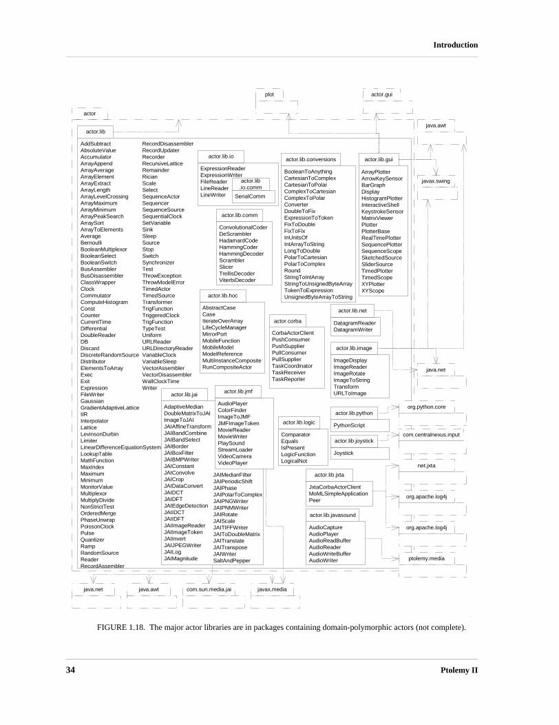
34 Ptolemy II
Introduction
FIGURE 1.18. The major actor libraries are in packages containing domain-polymorphic actors (not complete).
actor
actor.lib
AddSubtractAbsoluteValueAccumulatorArrayAppendArrayAverageArrayElementArrayExtractArrayLengthArrayLevelCrossingArrayMaximumArrayMinimumArrayPeakSearchArraySortArrayToElementsAverageBernoulliBooleanMultiplexorBooleanSelectBooleanSwitchBusAssemblerBusDisassemblerClassWrapperClockCommutatorComputeHistogramConstCounterCurrentTimeDifferentialDoubleReaderDBDiscardDiscreteRandomSourceDistributorElementsToArrayExecExitExpressionFileWriterGaussianGradientAdaptiveLatticeIIRInterpolatorLatticeLevinsonDurbinLimiterLinearDifferenceEquationSystemLookupTableMathFunctionMaxIndexMaximumMinimumMonitorValueMultiplexorMultiplyDivideNonStrictTestOrderedMergePhaseUnwrapPoissonClockPulseQuantizerRampRandomSourceReaderRecordAssembler
plot actor.gui
RecordDisassemblerRecordUpdaterRecorderRecursiveLatticeRemainderRicianScaleSelectSequenceActorSequencerSequenceSourceSequentialClockSetVariableSinkSleepSourceStopSwitchSynchronizerTestThrowExceptionThrowModelErrorTimedActorTimedSourceTransformerTrigFunctionTriggeredClockTrigFunctionTypeTestUniformURLReaderURLDirectoryReaderVariableClockVariableSleepVectorAssemblerVectorDisassemblerWallClockTimeWriter
BooleanToAnythingCartesianToComplexCartesianToPolarComplexToCartesianComplexToPolarConverterDoubleToFixExpressionToTokenFixToDoubleFixToFixInUnitsOfIntArrayToStringLongToDoublePolarToCartesianPolarToComplexRoundStringToIntArrayStringToUnsignedByteArrayTokenToExpressionUnsignedByteArrayToString
actor.lib.conversions
ComparatorEqualsIsPresentLogicFunctionLogicalNot
actor.lib.logic
ConvolutionalCoderDeScramblerHadamardCodeHammingCoderHammingDecoderScramblerSlicerTrellisDecoderViterbiDecoder
actor.lib.comm
ArrayPlotterArrowKeySensorBarGraphDisplayHistogramPlotterInteractiveShellKeystrokeSensorMatrixViewerPlotterPlotterBaseRealTimePlotterSequencePlotterSequenceScopeSketchedSourceSliderSourceTimedPlotterTimedScopeXYPlotterXYScope
actor.lib.gui
AudioCaptureAudioPlayerAudioReadBufferAudioReaderAudioWriteBufferAudioWriter
actor.lib.javasound
DatagramReaderDatagramWriter
actor.lib.net
ImageDisplayImageReaderImageRotateImageToStringTransformURLToImage
actor.lib.image
AdaptiveMedianDoubleMatrixToJAIImageToJAIJAIAffineTransformJAIBandCombineJAIBandSelectJAIBorderJAIBoxFilterJAIBMPWriterJAIConstantJAIConvolveJAICropJAIDataConvertJAIDCTJAIDFTJAIEdgeDetectionJAIIDCTJAIIDFTJAIImageReaderJAIImageTokenJAIInvertJAIJPEGWriterJAILogJAIMagnitude
actor.lib.jai
ExpressionReaderExpressionWriterFileReaderLineReaderLineWriter
actor.lib.io
AudioPlayerColorFinderImageToJMFJMFImageTokenMovieReaderMovieWriterPlaySoundStreamLoaderVideoCameraVideoPlayer
actor.lib.jmf
Joystick
actor.lib.joystick
JxtaCorbaActorClientMoMLSimpleApplicationPeer
actor.lib.jxta
PythonScript
actor.lib.python
java.awt
javax.swing
java.net
org.python.core
com.centralnexus.input
net.jxta
org.apache.log4j
org.apache.log4j
ptolemy.media
javax.mediajava.awt com.sun.media.jaijava.net
actor.lib.io.comm
SerialComm
JAIMedianFilterJAIPeriodicShiftJAIPhaseJAIPolarToComplexJAIPNGWriterJAIPNMWriterJAIRotateJAIScaleJAITIFFWriterJAIToDoubleMatrixJAITranslateJAITransposeJAIWriterSaltAndPepper
AbstractCaseCaseIterateOverArrayLifeCycleManagerMirrorPortMobileFunctionMobileModelModelReferenceMultiInstanceCompositeRunCompositeActor
actor.lib.hoc
actor.corba
CorbaActorClientPushConsumerPushSupplierPullConsumerPullSupplierTaskCoordinatorTaskReceiverTaskReporter

Heterogeneous Concurrent Modeling and Design 35
Introduction
actor.lib.pythonThis package provides an actor whose operation can be specified in Python.
1.5.5 User Interface Packages
The UI packages provide support for our XML file format, called MoML, and a visual interfacefor constructing models graphically, called Vergil. These packages are organized as shown in figures1.19 and 1.20. The intent of each package is described below:
actor.gui This package contains the configuration infrastructure, which supports modular construction of user interfaces that are themselves Ptolemy II models.
actor.gui.style This package contains classes that decorate attributes to serve as hints to a user interface about how to present these attributes to the user.
gui This package contains generically useful user interface components.media This package encapsulates a set of classes supporting audio and image processing.media.javasound
This package encapsulates a set of classes supporting audio and processing that depends on the JavaSound API
moml This package contains classes support our XML modeling markup language (MoML), which is used to describe Ptolemy II models.
moml.filter This package provides backward compatibility between Ptolemy release.plot This package and its subpackages provide two-dimensional signal plotting widgets.vergil This package and its subpackages contain the Ptolemy II graphical user interface. It
builds on Diva, a toolkit that extends Java 2D. For more information about Diva, see http://www.gigascale.org/diva.
1.5.6 Capabilities
Ptolemy II is a third generation system. Its immediate predecessor, Ptolemy Classic, still has activeusers and developers, particularly through a commercial product that is based partly on it, Agilent’sADS. Ptolemy II has a somewhat different emphasis, and through its use of Java, concurrency, andintegration with the network, is aggressively experimental. Some of the major capabilities in PtolemyII that we believe to be new technology in modeling and design environments include:
• Higher level concurrent design in Java. Java support for concurrent design is very low level, based on threads and monitors. Maintaining safety and liveness can be quite difficult [73][76]. Ptolemy II includes a number of domains that support design of concurrent systems at a much higher level of abstraction, at the level of their software architecture. Some of these domains use Java threads as an underlying mechanism, while others offer an alternative to Java threads that is much more efficient, scalable, and understandable.
• Actor-oriented classes, subclasses, and inheritance. Classes are the key modularity mechanism of object-oriented design. While actor-oriented frameworks have long leveraged this object-oriented mechanism (see [23]for example), they have largely stopped short of defining comparable modu-larity mechanisms that operate at the level of actor composition. Ptolemy II does this, and in a suf-

36 Ptolemy II
Introduction
FIGURE 1.19. Packages in Ptolemy II that support the user interfaces, including the MoML XML schema, plotters and other display infrastructure, and support for windows and application configurations.
actor
actor.gui
BrowserEffigyBrowserLauncherBrowserTableauColorAttributeCompositeActorApplicationConfigurationConfigurationEffigyConfigurerDebugListenerTableauDialogTableauEditorFactoryEditorPaneFactoryEditParametersDialogEffigyEffigyFactoryExpressionShellEffigyExpressionShellFrameExpressionShellTableauExternalTextEffigyExternalTextTableauGenerateCopyrightsHTMLAboutHTMLEffigyHTMLEffigyFactoryHTMLViewerHTMLViewerTableauInsideEntityEditorPaneFactoryJNLPUtilitiesJVMTableauLevelSkippingTableauFactoryLocationAttributeMatrixPaneMatrixTokenTableauModelDirectoryModelFrameModelPaneMoMLAppletMoMLApplicationMoMLSimpleApplicationMoMLSimpleStatisticalApplicationPlaceablePlotEffigyPlotTableauPlotTableauFramePortConfigurerPortConfigurerDialogPtExecuteApplicationPtolemyAppletPtolemyApplicationPtolemyDialogPtolemyEffigyPtolemyQueryPtolemyTableauFactoryPtolemyFrameRenameConfigurerRenameDialogRunTableauSizeAttributeTableauFrameTextEditorTextEditorTableauTextEffigyTableauTableauFactoryTokenEffigyTokenTableauTokenEffigyUnitConstraintsDialogUnitSolverDialogWindowPropertiesAttribute
moml
DocumentationEntityLibraryErrorHandlerHandlesInternalLinksImportAttributeLibraryAttributeMoMLAttributeMoMLChangeRequestMoMLFilterMoMLParserMoMLUndoEntryParserAttributeStreamErrorHandlerUndoContextVertex
data.expr
actor.gui.style
CheckBoxStyleChoiceStyleEditableChoiceStyleFileChooserStyleLineStyleNotEditableLineStyleParameterEditorStylePasswordStyleStyleConfigurerTextStyle
AddEditorFactoryAddIconBackwardCompatibilityClassChangesHideAnnotationNamesMultiportToSinglePortParameterNameChangesPortClassChangesPortNameChangesPropertyClassChangesRemoveEmptyPropertiesRemoveGraphicalClasses
moml.filter
plot
CmdLineArgExceptionEPSGraphicsEditListenerEditablePlotHistogramHistogramAppletPlotPlotAppletPlotApplicationPlotBoxPlotDataExceptionPlotFormatterPlotFramePlotLivePlotLiveAppletPlotPoint
plot.compat
PxgraphAppletPxgraphApplicationPxgraphParse
plot.plotml
EditablePlotMLAppletEditablePlotMLApplicationHistogramMLAppletHistogramMLApplicationHistogramMLParserPlotBoxMLParserPlotMLAppletPlotMLApplicationPlotMLFramePlotMLParser
media
AudioAudioViewerPicture
media.javasound
LiveSoundLiveSoundEventLiveSoundListenerSoundPlaybackSoundReaderSoundWriter
gui
BasicJAppletCancelExceptionCloseListenerComponentDialogGraphicalMessageHandlerJTextAreaExecMessageHandlerQueryQueryListenerShellInterpreterShellTextAreaStatusBarStreamExecSwingWorkerTop
java.awt javax.swingutil
com.microstar.xml
sun.audio javax.sound
moml.jxta
JXTAClassLoaderJXTALibrary

Heterogeneous Concurrent Modeling and Design 37
Introduction
FIGURE 1.20. Packages in Ptolemy II provide the Vergil visual editor.
vergil
MoMLViewerAppletTypeAnimatorAppletVergilApplicationVergilErrorHandler
ActorControllerActorEditorGraphControllerActorGraphFrameActorGraphModelActorGraphTableauActorInstanceControllerActorViewerGraphControllerClassDefinitionControllerExternalIOPortControllerIOPortControllerLinkController
vergil.actor
vergil.fsm
ArcFSMGraphControllerFSMGraphFrameFSMGraphModelFSMGraphTableauFSMViewerGraphControllerStateControllerTransitionController
AbstractBasicGraphModelBasicGraphControllerBasicGraphFrameEditorDropTargetExtendedGraphFrameIconControllerLocatableNodeControllerLocatableNodeDragInteractorNamedObjControllerNamedObjNodeModelNodeControllerFactoryParameterizedNodeControllerPopupMouseFilterRunnableGraphControllerWithIconGraphController
vergil.basic
vergil.icon
AttributeValueIconBoxedValueIconBoxedValuesIconCopyCatIconDynamicEditorIconEditIconFrameEditIconGraphControllerEditIconTableauEditorIconImageIconResizableAttributeControllerFactoryShapeIconSVGIconTextIconUpdatedValueIconValueIconXMLIcon
vergil.kernel
AnimationRendererAttributeControllerAttributeNodeModelCompositePtolemyModelDebugRendererLinkPortDialogFactoryRelationControllerRenameDialogFactoryVergilUtilities
vergil.tree
EntityTreeModelFullTreeModelPTreePtolemyTreeCellRendererTreeEditorTreeEditorPanelTreeTableauVisibleTreeModel
vergil.toolbox
AnnotationEditorFactoryAttributeBoundsManipulatorConfigureActionEditIconActionFigureActionFileEditorTableauFactoryGraphicElementMenuActionFactoryMenuItemFactoryPortSitePtolemyListCellRendererPtolemyMenuFactoryPtolemyTransferableRemoveIconActionSnapConstraintTextEditorConfigureFactoryTextEditorFactoryTextEditorForStringAttributesTextEditorTableauFactoryVisibleParameterEditorFactory
diva
InterfaceAutomatonGraphControllerInterfaceAutomatonGraphFrameInterfaceAutomatonGraphTableau
vergil.fsm.ia
vergil.fsm.modal
HierarchicalStateControllerHierarchicalStateControllerFactoryModalTableauFactoryModalTransitionController
domains.fsm java.awt javax.swing actor.gui gui moml
vergil.debugger
DebugControllerDebugProfileBreakpointDialogFactoryBreakpointConfigurerBreakpointConfigurerDialog

38 Ptolemy II
Introduction
ficiently general way to be applicable across a large suite of models of computation.• A truly polymorphic type system. Ptolemy Classic supported rudimentary polymorphism through
the “anytype” particle. Even with such limited polymorphism, type resolution proved challenging, and the implementation is ad-hoc and fragile. Ptolemy II has a more modern type system based on a partial order of types and monotonic type refinement functions associated with functional blocks. Type resolution consists of finding a fixed point, using algorithms inspired by the type system in ML [113]. The type system is described in [150] and [151].
• Domain-polymorphic actors. In Ptolemy Classic, actor libraries were separated by domain. Through the notion of subdomains, actors could operate in more than one domain. In Ptolemy II, this idea is taken much further. Actors with intrinsically polymorphic functionality can be written to operate in a much larger set of domains. The mechanism they use to communicate with other actors depends on the domain in which they are used. This is managed through a concept that we call a behavioral type system [80].
• Extensible XML-based file formats. XML is an established standard for representation of informa-tion that focuses on the logical relationships between pieces of information. Human-readable rep-resentations are generated with the help of style sheets. Ptolemy II uses XML as its primary format for persistent design data.
• Better modularization through the use of packages. Ptolemy II is divided into packages that can be used independently and distributed on the net, or drawn on demand from a server. This breaks with tradition in design software, where tools are usually embedded in huge integrated systems with interdependent parts.
• Branded, Packaged Configurations. Ptolemy II offers the ability to create separately branded, packages that pull in as much or as little of the infrastructure as is appropriate. Two examples are HyVisual [26] for hybrid systems modeling and VisualSense [12] for wireless and sensor network modeling. These “configurations” can have customized libraries of actors and directors, custom-ized editors, and customized on-line documentation. A “configuration” is defined by a Ptolemy II model, so creating one is relatively easy.
• Complete separation of the abstract syntax from the semantics. Ptolemy designs are structured as clustered graphs. Ptolemy II defines a clean and thorough abstract syntax for such clustered graphs, and separates into distinct packages the infrastructure supporting such graphs from mecha-nisms that attach semantics (such as dataflow, analog circuits, finite-state machines, etc.) to the graphs.
• Improved heterogeneity via a well-defined abstract semantics. Ptolemy Classic provided a worm-hole mechanism for hierarchically coupling heterogeneous models of computation. This mecha-nism is improved in Ptolemy II through the use of opaque composite actors, which provide better support for models of computation that are very different from dataflow, the best supported model in Ptolemy Classic. These include hierarchical concurrent finite-state machines and continuous-time modeling techniques.
• Thread-safe concurrent execution. Ptolemy models are typically concurrent, but in the past, sup-port for concurrent execution of a Ptolemy model has been primitive. Ptolemy II supports concur-rency throughout, allowing for instance for a model to mutate (modify its clustered graph structure) while the user interface simultaneously modifies the structure in different ways. Consis-tency is maintained through the use of monitors and read/write semaphores [62] built upon the lower level synchronization primitives of Java.
• Fully integrated expression language. The Ptolemy II expression language is a higher-order, richly

Heterogeneous Concurrent Modeling and Design 39
Introduction
expressive language that is fully integrated with actor-oriented modeling. The type system infer-ence mechanism propagates through expressions, parameters, and actor ports seamlessly.
• A software architecture based on object modeling. Since Ptolemy Classic was constructed, soft-ware engineering has seen the emergence of sophisticated object modeling [110][133][136] and design pattern [45] concepts. We have applied these concepts to the design of Ptolemy II, and they have resulted in a more consistent, cleaner, and more robust design. We have also applied a simpli-fied software engineering process that includes systematic design and code reviews [129].
1.5.7 Experimental Capabilities
Ptolemy II includes a number of still evolving experimental capabilities. These include.• Distributed models. Ptolemy II has (still preliminary) infrastructure supporting distributed model-
ing using CORBA, Java RMI, or lower-level networking primitives. Ptolemy II has (still prelimi-nary) support for migrating software components.
• Higher-order components. Ptolemy II has a (still preliminary) library of actors that operate on Ptolemy II models rather than just on data. While Ptolemy Classic had such higher-order compo-nents, in Ptolemy Classic the manipulations of the model occurred as part of the initialization phase of the execution. In Ptolemy II, they can occur during the execution of the model. Examples include the MobileModel, which supports an actor-oriented version of mobile code, and ModalM-odel, which supports modal behavior.
• Lifecycle management components. Ptolemy II has a (still preliminary) library of actors that man-age the lifecycle of other Ptolemy II models. Examples include RunCompositeActor, which on each firing performs a complete execution of the contained model, and ModelReference, which performs a similar function on a model defined in a separate file or URL.
• Component specialization. Ptolemy II has an evolving code generation mechanism that is very dif-ferent from that in Ptolemy Classic. In Ptolemy Classic, each component has to have a definition in the target language, and the code generator merely stitches together these components. In Ptolemy II, components are defined in Java, and the Java definition is parsed. An API for performing opti-mization transformations on the abstract syntax tree is defined, and then compiler back ends can be used to generate target code. An implementation of this approach is described in [119], [120], [144] and [145].
• Cal actor definition language. Actors have traditionally been defined in Java for Ptolemy II. How-ever, static analysis of Java programs for properties that are important at the actor-oriented level is extremely challenging, at best, and impossible at worst. The Cal actor language provides a way to define actors so that these properties are statically inferable from the actor definition [38].
• Experimental models of computation. Ptolemy II includes a number of experimental models of computation, including Giotto [55], timed-multitasking [98], distributed discrete-events [34], and a push-pull component model called component interaction (CI) [154].
1.5.8 Future Capabilities
Capabilities that we anticipate making available in the future include:• Integrated verification tools. Modern verification tools based on model checking [57] could be
integrated with Ptolemy II at least to the extent that finite state machine models can be checked. We believe that the separation of control logic from concurrency will greatly facilitate verification, since only much smaller cross-sections of the system behavior will be offered to the verification

40 Ptolemy II
Introduction
tools.• Reflection of dynamics. Java supports reflection of static structure, but not of dynamic properties
of process-based objects. For example, the data layout required to communicate with an object is available through the reflection package, but the communication protocol is not. We plan to extend the notion of reflection to reflect such dynamic properties of objects.
• Meta modeling. The domains in Ptolemy II are constructed based on an intuitive understanding of a useful class of modeling techniques, and then the support infrastructure for specifying and exe-cuting models in the domain are built by hand by writing Java code. Others have built tools that have the potential of improving on this situation by meta modeling. In Dome (from Honeywell) and GME [69], for example, a modeling strategy itself is modeled, and user interfaces supporting that modeling strategy are synthesized from that model. We can view the current component-based architecture of Vergil as a starting point in this direction. In the future, we expect to see much more use of Ptolemy II itself to define and construct Ptolemy II domains and their user interfaces.
1.6 Acknowledgements
There have been many participants in the Ptolemy Project over the years. So many, that we may(inadvertently) omit some names here. With apologies to those people, we list the contributors. Theprincipal authors of version 6.0 are• Christopher Brooks• Elaine Cheong• Edward Lee• Jackie Leung• Yang Zhao• Haiyang Zheng• Gang Zhou• Ye ZhouMajor contributors to earlier versions of Ptolemy II include:• John Reekie• Chamberlain Fong• John Davis, II• Mudit Goel• Rowland Johnson• Bilung Lee• Jie Liu• Xiaojun Liu• Lukito Muliadi• Stephen Neuendorffer• Neil Smyth• Jeff Tsay• Yuhong XiongOther contributors include Jim Armstrong, Vincent Arnould, Philip Baldwin, Frederic Boulanger,Raymond Cardillo, Adam Cataldo, Chris Chang, Albert Chen, Elaine Cheong, Colin Cochran, Brieuc

Heterogeneous Concurrent Modeling and Design 41
Introduction
Desoutter, Pedro Domecq, Johan Eker, Thomas Huining Feng, Tobin Fricke, Geroncio Galicia, BenHorowitz, Heloise Hse, Efrat Jaeger, Jörn Janneck, Zoltan Kemenczy, Bart Kienhuis, Christoph MeyerKirsch, Sanjeev Kohli, Vinay Krishnan, Robert Kroeger, Daniel Lázaro Cuadrado, David Lee,Michael Leung, John Li, Andrew Mihal, Eleftherios Matsikoudis, Aleksandar Necakov, Mike KofiOkyere, Sarah Packman, Shankar Rao, Rakesh Reddy, Adriana Ricchiuti, Sonia Sachs, Ismael M.Sarmiento, Michael Shilman, Sean Simmons, Mandeep Singh, Peter N. Steinmetz, Dick Stevens, MaryStewart, Ned Stoffel, Manda Sutijono, Neil Turner, Guillaume Vibert, Kees Vissers, Brian K. Vogel,Yuke Wang, Xavier Warzee, Scott Weber, Paul Whitaker, Winthrop Williams, Ed Willink, MichaelWirthlin, William Wu, Xiaowen Xin, Paul Yang, James Yeh, Nick Zamora, and Charlie Zhong.
This project is currently supported by the Center for Hybrid and Embedded Software Systems(CHESS) at UC Berkeley, which receives support from the National Science Foundation (NSF award#CCR-0225610), the State of California Micro Program, and the following companies: Agilent,DGIST, General Motors, Hewlett Packard, Microsoft, National Instruments, and Toyota.

42 Ptolemy II
Introduction
Appendix A: UML — Unified Modeling Language
UML (the unified modeling language) [43][128] defines a suite of visual syntaxes for describingvarious aspects of software architecture. We make heavy use of two of these visual syntaxes, packagediagrams and static structure diagrams. These syntaxes are summarized here. As with most descriptivesyntaxes, any use of the syntax involves certain stylistic choices. These stylistic choices are not part ofUML, but nonetheless can be important to understanding the diagrams. We explain the style that weuse here.
A.1 Package Diagrams
Figures 1.12 and 1.17 show UML package diagrams, which have a simple syntax. A package isgiven as a box with a tab, with the tab containing the name of the package. Subpackages are enclosedin the box of the parent package, and package dependencies are indicated with arrows. A packagedependency occurs when a Java file in a package includes a class in another package (using import inJava).
A.2 Static Structure Diagrams
Figure 1.16 is a different kind of UML diagram, called a static structure diagram or class diagram.It represents the relationships between classes, including inheritance relationships, containment rela-tionships, and cross references. These relationships are called an object model, and represent manyessential features about the design.
A.2.1 Classes
A simplified static structure diagram for some Ptolemy II classes is shown in figure 1.21. In thisdiagram, each class is shown in a box. The class name is at the top of each box, its attributes are belowthat, and its methods below that. Thus, each box is divided into three segments separated by horizontallines. The attributes are members of the Java classes, which may be public, package friendly, pro-tected, or private. Private members are prefixed by a minus sign “-”, as for example the _containerattribute of Port. Although private members are not visible directly to users of the class, they maynonetheless be a useful part of the object model because they indicate the state information containedby an instance of the class. Public members have a leading “+” and protected methods a leading “#” ina UML diagram. There are no public or protected members shown in figure 1.21. The type of a mem-ber is indicated after a colon, so for example, the _container member of Port is of type Entity.
Methods, which are shown below attributes, also have a leading “+” for public, “#” for protected,and “-” for private. Our object models do not show private methods, since they are not inherited andare not visible in the interface to the object. Figure 1.21 shows a number of public methods and oneprotected method, _checkLink() in Port. The return type of a method is given after a colon, so forexample, linkedRelationList() of Port returns a List.
Although not usually included in UML diagrams, our diagrams show class constructors. They arelisted first among the methods and have names that are the same as the name of the class. No returntype is shown. For completeness, our object models typically show all public and protected methods ofthese classes, although a proper object model might only show those relevant to the issues being dis-cussed. Figure 1.21 does not show all methods, so that we can simplify the discussion of UML. Our

Heterogeneous Concurrent Modeling and Design 43
Introduction
diagrams do not include deprecated methods or methods that are present in parent classes.Arguments to a method or constructor are shown in parentheses, with the types after a colon, so for
example, Attribute shows a single constructor that takes two arguments, one of type NamedObj andthe other of type String.
A.2.2 Inheritance
Subclasses are indicated by lines with white triangles (or outlined arrow heads). The class on theside of the arrow head is the superclass or base class. The class on the other end is the subclass orderived class. The derived class is said to specialize the base class, or conversely, the base class to gen-eralize the derived class. The derived class inherits all the methods shown in the base class and mayoverride or some of them. In our object models, we do not explicitly show methods that override thosedefined in a base class or are inherited from a base class. For example, in figure 1.21, Entity has all themethods NamedObj, and may override some of those methods, but only shows the methods it adds.Thus, the complete set of methods of a class is cumulative. Every class has its own methods plus thoseof all its superclasses.
An exception to this is constructors. In Java, constructors are not inherited. Thus, in our class dia-
FIGURE 1.21. Simplified static structure diagram for some Ptolemy II classes. This diagram illustrates fea-tures of UML syntax that we use.
Entity
+getPort(name : String) : Port+isAtomic() : boolean+isOpaque() : boolean+portList() : List
CompositeEntity
AtomicActor
Director
«Interface»Executable
+fire()+initialize()+postfire() : boolean+prefire() : boolean+preinitialize()+wrapup()
CompositeActor0..n
0..1
«Interface»Actor
+getDirector() : Director
NamedObj
+getAttribute(name : String) : Attribute+attributeList() : List
Attribute
+Attribute(container : NamedObj, name : String)0..n
0..1
Port
+link(relation : Relation)+linkedRelationList() : List#_checkLink(relation : Relation)
-_container : Entity
Relation
+linkedPortList() : List
0..n
0..nlink
link
ComponentRelation
0..1 0..n
container
0..1
0..n
container0..1 0..n
container
0..1
0..1
container

44 Ptolemy II
Introduction
grams, the only constructors available for a class are those shown in the box defining the class. Figure1.21 does not show all the constructors of these classes, for simplicity.
Classes shown in boxes outlined with dashed lines, such as NamedObj in figure 1.21, are fullydescribed elsewhere. This is not standard UML notation, but it gives us a convenient way to partitiondiagrams. Often, these classes belong to another package.
A.2.3 Interfaces
Figure 1.21 also shows two examples of interfaces, Executable and Actor. An interface is indi-cated by the label “<<Interface>>” and by italics in the name. An interface defines a set of methodswithout providing an implementation for them. It cannot be instantiated, and therefore has no construc-tors. When a class implements an interface, the object model shows the relationship with a dotted-linewith an arrow. Any concrete class (one that can be instantiated) that implements an interface must pro-vide implementations of all its methods. In our object models, we do not show those methods explic-itly in the concrete class, just like inherited methods, but their presence is implicit in the relationship tothe interface.
One interface can extend another. For example, in figure 1.21, Actor extends Executable. Thismeans that any concrete class that implements Actor must implement the methods of Actor and Exe-cutable.
We will occasionally show abstract classes, which are like interfaces in that they cannot be instan-tiated, but unlike interfaces in that they may provide default implementations for some methods andmay even have private members. Abstract classes are indicated by italics in the class name. There areno abstract classes in figure 1.21.
A.2.4 Associations
Inheritance and implementation are types of associations between entities in the object model.Associations of other types are indicated by other lines, often annotated with ranges like “0..n” or withdiamonds on one end or the other.
Aggregations are shown as associations with diamonds. For example, an Entity is an aggregationof any number (0..n) instances of Port. More strongly, we say that a Port is contained by 0 or 1instances of Entity. By containment, we mean that a port can only be contained by a single Entity. In aweaker form of aggregation, more than one aggregate may refer to the same component. The strongerform of aggregation (containment) is indicated by the filled diamond, while the weaker form is indi-cated by the unfilled diamond. There are no unfilled diamonds in figure 1.21. In fact, they are fairlyrare in Ptolemy II, since many of its architectural features depend on containment relationships, wherean object can have at most one container.
The relationship between Entity and CompositeEntity is particularly interesting. An instance ofCompositeEntity can contain any number of instances of Entity, but CompositeEntity is derived fromEntity. Thus, a CompositeEntity can contain any number of instances of either Entity or CompositeEn-tity. This is the classic Composite design pattern [45], which supports arbitrarily deeply nested con-tainment hierarchies.
In figure 1.21, a CompositeActor is an aggregation of AtomicActors and CompositeActors. Thesetwo aggregation relations are derived from the aggregation relationship between Entity and Composi-teEntity. This derived association is indicated with a dashed line with an open arrowhead.

Heterogeneous Concurrent Modeling and Design 45
Introduction
Appendix B: Ptolemy II Naming Conventions
We have made an effort to be consistent about naming of classes, methods and members. Thisappendix briefly describes our policy in just enough detail to help read this documentation. For thecomplete coding style guide, see [20].
B.1 Classes
Class names are capitalized with internal word boundaries also capitalized (as in “CompositeEn-tity”). Most names are made up of complete words (“CompositeEntity” rather than “CompEnt”)1.Interface names suggest their potential (as in “Executable,” which means “can be executed”).
Despite having packages to divide up the namespace, we attempt nonetheless to keep class namesunique. This helps avoid confusion and bugs that may arise from having Java import statements in thewrong order. In many cases, a domain includes a specialized version of some more generic class. Inthis case, we create a unique name by prefixing the generic name with the domain name. For example,while Director is a base class in the actor package, DEDirector is a derived class in the DE domain.
For the most part, we try to avoid prefixing actor names with the domain name. e.g., we defineDelay rather than DEDelay. Occasionally however, the domain prefix is useful to distinguish two ver-sions of some similar functionality, both of which might be useful in a domain. For example, the DEdomain can use actors derived from Transformer or from DETransformer, where the latter is special-ized to DE.
B.2 Members
Member names are not capitalized, although internal word boundaries usually are (e.g. “declared-Type”). If the member is private or protected, then its name begins with a leading underscore (e.g.“_declaredType”).
B.3 Methods
Method names are similar to member names, in that they are not capitalized, except on internalword boundaries. Private and protected methods have a leading underscore. In text referring to meth-ods, the method name is followed by open and close parentheses, as in “getName().” Usually, no argu-ments are given, even if the method takes arguments.
Method names that are plural, such as insideRelations(), usually return an enumeration (or some-times an array, or an iterator). Methods that return Lists are usually of the form portList().
1. There are some (perhaps regrettable) exceptions to this, such as NamedObj.

46 Ptolemy II
Introduction

Heterogeneous Concurrent Modeling and Design 47
2 Using Vergil
Authors: Edward A. LeeSteve Neuendorffer
2.1 Introduction
There are many ways to use Ptolemy II. It can be used as a framework for assembling softwarecomponents, as a modeling and simulation tool, as a block-diagram editor, as a system-level rapid pro-totyping application, as a toolkit supporting research in component-based design, or as a toolkit forbuilding Java applications. This chapter introduces its use as a modeling and simulation tool.
In this chapter, we describe how to graphically construct models using Vergil, a graphical userinterface (GUI) for Ptolemy II. Figure 2.1 shows a simple Ptolemy II model in Vergil, showing thegraph editor, one of several editors available in Vergil. Keep in mind as you read this document thatgraphical entry of models is only one of several possible entry mechanisms available in Ptolemy II. Forexample, you can define models in Java, as shown in figure 1.5, or in XML, as shown in figure 1.3 ofthe previous chapter. Moreover, only some of the execution engines (called domains) are describedhere. A major emphasis of Ptolemy II is to provide a framework for the construction of modeling anddesign tools, so the specific modeling and design tools described here should be viewed as representa-tive of our efforts.
2.2 Quick Start
This section shows how to start Vergil, how to execute and explore pre-built models, and how toconstruct your own models.
2.2.1 Starting Vergil
First start Vergil. From the command line, enter “vergil”, or if you installed on Windows, selectPtolemy II and Vergil in the Start menu1, or click on a Web Start link on a web page supporting the web

48 Ptolemy II
Using Vergil
edition. You should see an initial welcome window that looks like the one in figure 2.2. Feel free toexplore the links in this window. The “Quick tour” link takes you to the page shown in figure 2.3.
1. Depending on your installation, you could have several versions of Vergil available in the Start menu. This doc-ument assumes you select “Vergil - Full.” There are separate tutorial documents for “Vergil - HyVisual” (which is specialized for modeling hybrid systems) and “Vergil - VisualSense” (which is specialized for modeling wire-less and sensor network systems).
FIGURE 2.1. Example of a Vergil window.
FIGURE 2.2. Initial welcome window.

Heterogeneous Concurrent Modeling and Design 49
Using Vergil
2.2.2 Executing a Pre-Built Model: A Signal Processing Example
The first example listed under “Basic Modeling Capabilities” on the quick tour page is the modelshown in figure 2.1. It creates a sinusoidal signal, multiplies it by a sinusoidal carrier, adds noise, andthen estimates the power spectrum. You can execute this model in either of two ways. First, you canselect Run Window in the View menu, and then click on Go. The result is shown in figure 2.4. Theupper plot shows the spectrum of the time-domain signal shown in the lower plot. Note the four peaks,which indicate the modulated sinusoid. In the run window you can adjust the frequencies of the signaland the carrier as well as the amount of noise. These can also be adjusted in the block diagram in figure2.1 by double clicking on the bulleted parameters near the upper right of the window.
The second alternative for running the model is to click on the run button in the toolbar, which isindicated by a red triangle pointing to the right. If you use this alternative, then the two signal plots aredisplayed in their own windows.
FIGURE 2.3. The quick-tour page.

50 Ptolemy II
Using Vergil
You can study the way the model is constructed in figure 2.1. Note the Expression actor in the mid-dle, whose icon indicates the expression being calculated: “signal*carrier + noise”. The identi-fiers in this expression, signal, carrier, and noise refer to the input ports by name. The names ofthese ports are shown in the diagram. The Expression actor is a very flexible actor in the Ptolemy IIactor library. It can have any number of input ports, with arbitrary names, and uses a rich and expres-sive expression language to specify the value of the output as a function of the inputs (and parametersof the containing model, if desired).
Three of the actors in figure 2.1 are composite actors, which means that their implementation isitself given as a block diagram. Composite actors are indicated visually by the red outline. You caninvoke the “Open Actor” context menu choice to reveal the implementation, as shown in figure 2.5,which shows the implementation of the Signal Source in figure 2.1. It is evident from the block dia-gram how a sinusoidal signal is generated.
2.2.3 Executing a Pre-Built Model: A Continuous-Time Example
A key principle of the Ptolemy II system is that the model of computation that defines the meaningof a block diagram is not built-in, but is rather specified by the director component that is included inthe model. The box labeled “SDF Director” in figures 2.1 and 2.5 specifies that these block diagramshave synchronous dataflow semantics, which is explained further below. The second example under“Basic Modeling Capabilities” in the quick tour of figure 2.3, by contrast, has continuous-time seman-tics (the one labeled “Continuous-Time Modeling”). The example is the well-known Lorenz attractor,a non-linear feedback system that exhibits chaotic behavior.
FIGURE 2.4. The run window for the model shown in figure 2.1.

Heterogeneous Concurrent Modeling and Design 51
Using Vergil
The Lorenz attractor model, shown in figure 2.6, is a block diagram representation of a set of non-linear ordinary differential equations. The blocks with integration signs in their icons are integrators.At any given time t, their output is given by
, (1)
where is the initial state of the integrator, is the start time of the model, and is the input sig-nal. Note that since the output is the integral of the input, then at any given time, the input is the deriv-ative of the output,
. (2)
FIGURE 2.5. Invoke Open Actor on composite actors to reveal their implementation.
x t( ) x t0( ) x· τ( ) τd
t0
t
∫+=
x t0( ) t0 x·
x· t( )td
d x t( )=

52 Ptolemy II
Using Vergil
Thus, the system describes either an integral equation or a differential equation, depending on which ofthese two forms you use.
Let the output of the top integrator in figure 2.6 be , the output of the middle integrator be ,and the output of the bottom integrator be . Then the equations described by figure 2.6 are
. (3)
For each equation, the expression on the right is implemented by an Expression actor, whose iconshows the expression. Each expression refers to parameters (such as lambda for and sigma for )and input ports of the actor (such as x1 for and x2 for ). The names of the input ports are notshown in the diagram, but if you linger over them with the mouse cursor, the name will pop up in atooltip. The expression in each Expression actor can be edited by double clicking on the actor, and theparameter values can be edited by double clicking on the parameters, which are shown next to bulletson the right.
The integrators each also have initial values, which you can examine and change by double click-ing on the corresponding integrator icon. These define the initial values of , , and , respec-tively. For this example, all three are set to 1.0.
The Continuous-Time (CT) Solver, shown at the upper left, manages a simulation of the model. Itcontains a sophisticated ODE solver, and to use it effectively, you will need to understand some of its
FIGURE 2.6. A block diagram representation of a set of nonlinear ordinary differential equations.
x1 x2x3
x· 1 t( ) σ x2 t( ) x1 t( )–( )=
x· 2 t( ) λ x3 t( )–( )x1 t( ) x2 t( )–=
x· 3 t( ) x1 t( )x2 t( ) bx3 t( )–=
λ σx1 x2
x1 x2 x3

Heterogeneous Concurrent Modeling and Design 53
Using Vergil
parameters. The parameters are accessed by double clicking on the solver box, which results in the dia-log shown in figure 2.7. The simplest of these parameters are the startTime and the stopTime, which areself-explanatory. They define the region of the time line over which a simulation will execute.
To execute the model, you can click on the run button in the toolbar (with a red triangle icon), oryou can open the Run Window in the View menu. In the former case, the model executes, and theresults are plotted in their own window, as shown in figure 2.8. What is plotted is vs. forvalues of t in between startTime and stopTime.
Like the Lorenz model, a typical continuous-time model contains integrators in feedback loops, ormore elaborate blocks that realize linear and non-linear dynamical systems given abstract mathemati-
FIGURE 2.7. Dialog box showing solver parameters for the model in figure 2.6.
FIGURE 2.8. Result of running the Lorenz model using the run button in the toolbar.
x1 t( ) x2 t( )

54 Ptolemy II
Using Vergil
cal representations of them (such as Laplace transforms). In the next section, we will explore how tobuild a model from scratch.
2.2.4 Creating a New Model
Create a new model by selecting File->New->Graph Editor in the welcome window. You shouldsee something like the window shown in figure 2.9. Ignoring the menus and toolbar for a moment, onthe left is a palette of objects that can be dragged onto the page on the right. To begin with, the page onthe right is blank. Open the Actors library in the palette, and go into the Sources library. Find the Constactor under GenericSources and drag an instance over onto the blank page. Then go into the Sinkslibrary (GenericSinks sublibrary) and drag a Display actor onto the page. Each of these actors can bedragged around on the page. However, we would like to connect one to the other. To do this, drag aconnection from the output port on the right of the Const actor to the input port of the Display actor.Lastly, open the Directors library and drag an SDFDirector onto the page. The director gives a mean-ing (semantics) to the graph, but for now we don’t have to be concerned about exactly what that is.
Now you should have something that looks like figure 2.10. The Const actor is going to create ourstring, and the Display actor is going to print it out for us. We need to take care of one small detail tomake it look like figure 2.10: we need to tell the Const actor that we want the string “Hello World”. Todo this we need to edit one of the parameters of the Const. To do this, either double click on the Constactor icon, or right click1 on the Const actor icon and select “Configure”. You should see the dialogbox in figure 2.11. Enter the string "Hello World" for the value parameter and click the Commit button.Be sure to include the double quotes, so that the expression is interpreted as a string.
1. On a Macintosh, which typically has only one mouse button, instead of right clicking, hold the control key and click the one button.
FIGURE 2.9. An empty Vergil Graph Editor.
library of components
navigation area
model-building area

Heterogeneous Concurrent Modeling and Design 55
Using Vergil
You may wish to save your model, using the File menu. File names for Ptolemy II models shouldend in “.xml” or “.moml” so that Vergil will properly process the file the next time you open that file.
2.2.5 Running the Model
To run the example, go to the View menu and select the Run Window. If you click the “Go” button,you will see a large number of strings in the display at the right. To stop the execution, click the “Stop”button. To see only one string, change the iterations parameter of the SDF Director to 1, which can bedone in the run window, or in the graph editor in the same way you edited the parameter of the Constactor before. The run window is shown in figure 2.12.
FIGURE 2.10. The Hello World example.
FIGURE 2.11. The Const parameter editor.

56 Ptolemy II
Using Vergil
2.2.6 Making Connections
The model constructed above contained only two actors and one connection between them. If youmove either actor (by clicking and dragging), you will see that the connection is routed automatically.We can now explore how to create and manipulate more complicated connections.
First create a model in a new graph editor that includes an SDFDirector, a Ramp actor (found inthe Sources) library, a Display actor, and a SequencePlotter actor, found in the Sinks library, as shownin figure 2.13. Suppose we wish to route the output of the Ramp to both the Display and the Sequence-Plotter. If we simply attempt to make the connections, we get the exception shown in figure 2.14.Don’t panic! Exceptions are normal and common. The key information in this exception report is thetext:
FIGURE 2.12. Execution of the Hello World example.
FIGURE 2.13. Three unconnected actors in a model.
FIGURE 2.14. Exception that occurs if you attempt to simply wire the output of the Ramp in figure 2.14 to the inputs of the other two actors.

Heterogeneous Concurrent Modeling and Design 57
Using Vergil
Attempt to link more than one relation to a single port.
The last line gives the names of the objects involved, which in this case are:
in .relation.Ramp.output and .relation.relation2
(This assumes the model has been saved under the name “relation.”) In Ptolemy II models, all objectshave a dotted name. The dots separate elements in the hierarchy. Thus, “.relation.Ramp.output” is anobject named “output” contained by an object named “Ramp”, which is contained by an object named“relation” (the model itself). The model acquires a name when we save it.
Why did this exception occur? Ptolemy II supports two distinct flavors of ports, indicated in thediagrams by a filled triangle or an unfilled triangle. The output port of the Ramp actor is a single port,indicated by a filled triangle, which means that it can only support a single connection. The input portof the Display and SequencePlotter actors are multiports, indicated by unfilled triangles, which meansthat they can support multiple connections. Each connection is treated as a separate channel, which is apath from an output port to an input port (via relations) that can transport a single stream of tokens.
So how do we get the output of the Ramp to the other two actors? We need an explicit relation inthe diagram. A relation is represented in the diagram by a black diamond, as shown in figure 2.15. Itcan be created by either control-clicking on the background or by clicking on the button in the toolbarwith the black diamond on it.
Making a connection to a relation can be tricky, since if you just click and drag on the relation, the relation gets selected and moved. To make a connection, hold the control button while clicking and dragging on the relation.1
In the model shown in figure 2.15, the relation is used to broadcast the output from a single port toa number of places. The single port still has only one connection to it, a connection to a relation. Rela-tions can also be used to control the routing of wires in the diagram. However, as of the 4.0 release ofPtolemy II, a connection can only have a single relation on it, so the degree to which routing can becontrolled is limited.
1. On a Macintosh, hold the command key rather than the control key.
FIGURE 2.15. A relation can be used to broadcast an output from a single port.
Click here to createa relation, or control-click on the background.
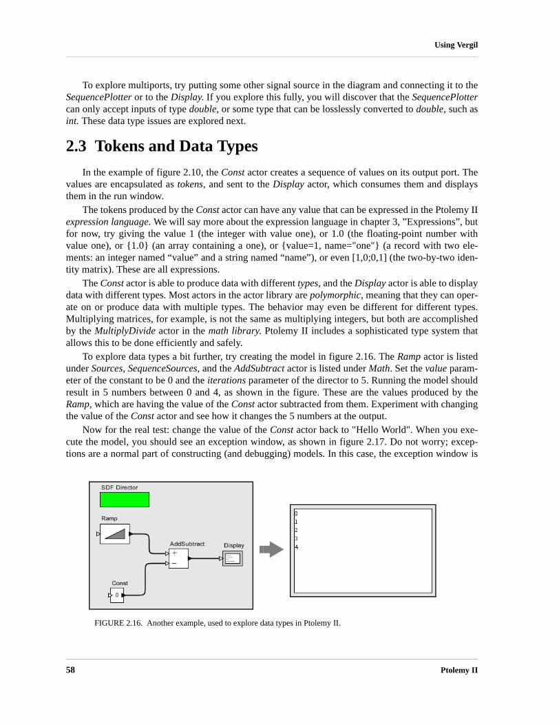
58 Ptolemy II
Using Vergil
To explore multiports, try putting some other signal source in the diagram and connecting it to theSequencePlotter or to the Display. If you explore this fully, you will discover that the SequencePlottercan only accept inputs of type double, or some type that can be losslessly converted to double, such asint. These data type issues are explored next.
2.3 Tokens and Data Types
In the example of figure 2.10, the Const actor creates a sequence of values on its output port. Thevalues are encapsulated as tokens, and sent to the Display actor, which consumes them and displaysthem in the run window.
The tokens produced by the Const actor can have any value that can be expressed in the Ptolemy IIexpression language. We will say more about the expression language in chapter 3, ”Expressions”, butfor now, try giving the value 1 (the integer with value one), or 1.0 (the floating-point number withvalue one), or {1.0} (an array containing a one), or {value=1, name="one"} (a record with two ele-ments: an integer named “value” and a string named “name”), or even [1,0;0,1] (the two-by-two iden-tity matrix). These are all expressions.
The Const actor is able to produce data with different types, and the Display actor is able to displaydata with different types. Most actors in the actor library are polymorphic, meaning that they can oper-ate on or produce data with multiple types. The behavior may even be different for different types.Multiplying matrices, for example, is not the same as multiplying integers, but both are accomplishedby the MultiplyDivide actor in the math library. Ptolemy II includes a sophisticated type system thatallows this to be done efficiently and safely.
To explore data types a bit further, try creating the model in figure 2.16. The Ramp actor is listedunder Sources, SequenceSources, and the AddSubtract actor is listed under Math. Set the value param-eter of the constant to be 0 and the iterations parameter of the director to 5. Running the model shouldresult in 5 numbers between 0 and 4, as shown in the figure. These are the values produced by theRamp, which are having the value of the Const actor subtracted from them. Experiment with changingthe value of the Const actor and see how it changes the 5 numbers at the output.
Now for the real test: change the value of the Const actor back to "Hello World". When you exe-cute the model, you should see an exception window, as shown in figure 2.17. Do not worry; excep-tions are a normal part of constructing (and debugging) models. In this case, the exception window is
FIGURE 2.16. Another example, used to explore data types in Ptolemy II.

Heterogeneous Concurrent Modeling and Design 59
Using Vergil
telling you that you have tried to subtract a string value from an integer value, which doesn’t makemuch sense at all (following Java, adding strings is allowed). This is an example of a type error.
Exceptions can be a very useful debugging tool, particularly if you are developing your own com-ponents in Java. To illustrate how to use them, click on the Display Stack Trace button in the exceptionwindow of figure 2.17. You should see the stack trace shown in figure 2.18. This window displays theexecution sequence that resulted in the exception. For example, the line
at ptolemy.data.IntToken.subtract(IntToken.java:547)
indicates that the exception occurred within the subtract() method of the class ptolemy.data.IntToken,at line 547 of the source file IntToken.java. Since Ptolemy II is distributed with source code (most
FIGURE 2.17. An example that triggers an exception when you attempt to execute it. Strings cannot be sub-tracted from integers.
FIGURE 2.18. Stack trace for the exception shown in figure 2.17.

60 Ptolemy II
Using Vergil
installation mechanisms at least offer the option of installing the source), this can be very useful infor-mation. For type errors, you probably do not need to see the stack trace, but if you have extended thesystem with your own Java code, or you encounter a subtle error that you do not understand, then look-ing at the stack trace can be very illuminating.
To find the file IntToken.java referred to above, find the Ptolemy II installation directory. If thatdirectory is $PTII, then the location of this file is given by the full class name, but with the periodsreplaced by slashes; in this case, it is at $PTII/ptolemy/data/IntToken.java (the slashes might be back-slashes under Windows).
Let’s try a small change to the model to get something that does not trigger an exception. Discon-nect the Const from the lower port of the AddSubtract actor and connect it instead to the upper port, asshown in figure 2.19. You can do this by selecting the connection and deleting it (using the delete key),then adding a new connection, or by selecting it and dragging one of its endpoints to the new location.Notice that the upper port is an unfilled triangle; this indicates that it is a multiport, meaning that youcan make more than one connection to it. Now when you run the model you should see strings like“0HelloWorld”, as shown in the figure.
There are two interesting things going on here. The first is that, as in Java, strings are added byconcatenating them. The second is that the integers from the Ramp are converted to strings and concat-enated with the string “Hello World”. All the connections to a multiport must have the same type. Inthis case, the multiport has a sequence of integers coming in (from the Ramp) and a sequence of strings(from the Const).
Ptolemy II automatically converts the integers to strings when integers are provided to an actorthat requires strings. But in this case, why does the AddSubtract actor require strings? Because itwould not work to require integers; the string “Hello World” would have to be converted to an integer.As a rough guideline, Ptolemy II will perform automatic type conversions when there is no loss ofinformation. An integer can be converted to a string, but not vice versa. An integer can be converted toa double, but not vice versa. An integer can be converted to a long, but not vice versa. The details areexplained in the Data chapter of Volume 2, but many users will not need to understand the full sophis-tication of the system. You should find that most of the time it will just do what you expect.
To further explore data types, try modifying the Ramp so that its parameters have different types.For example, try making init and step strings.
FIGURE 2.19. Addition of a string to an integer.

Heterogeneous Concurrent Modeling and Design 61
Using Vergil
2.4 Hierarchy
Ptolemy II supports (and encourages) hierarchical models. These are models that contain compo-nents that are themselves models. Such components are called composite actors. Consider a small sig-nal processing problem, where we are interested in recovering a signal based only on noisymeasurements of it. We will create a composite actor modeling a communication channel that addsnoise, and then use that actor in a model.
2.4.1 Creating a Composite Actor
First open a new graph editor and drag in a CompositeActor from the Utilities library. This actor isgoing to add noise to our measurements. First, using the context menu (obtained by right clicking1
over the composite actor), select “Customize Name”, and give the composite a better name, like“Channel”, as shown in figure 2.20. Then, using the context menu again, select “Open Actor” on theactor. You should get a blank graph editor, as shown in figure 2.21. The original graph editor is stillopen. To see it, move the new graph editor window by dragging the title bar of the window.
2.4.2 Adding Ports to a Composite Actor
First we have to add some ports to the composite actor. There are several ways to do this, but click-ing on the port buttons in the toolbar is probably the easiest. You can explore the ports in the toolbar bylingering with the mouse over each button in the toolbar. A tool tip pops up that explains the button.The buttons are summarized in figure 2.22. Create an input port and an output port and rename theminput and output by right clicking on the ports and selecting “Customize Name”. Note that, as shown infigure 2.23, you can also right click2 on the background of the composite actor and select ConfigurePorts to change whether a port is an input, an output, or a multiport. The resulting dialog also allowsyou to set the type of the port, although much of the time you will not need to do this, since the typeinference mechanism in Ptolemy II will figure it out from the connections. You can also specify thedirection of a port (where it appears on the icon; by default inputs appear on the left, outputs on theright, and ports that are both inputs and outputs appear on the bottom of the icon). You can also control
1. On a Macintosh, control-click.2. On a Macintosh, control-click.
FIGURE 2.20. Changing the name of an actor.

62 Ptolemy II
Using Vergil
whether the name of the port is shown outside the icon (by default it is not), and even whether the portis shown at all. The “Units” column will be discussed further below.
FIGURE 2.21. Looking inside a composite actor.
FIGURE 2.22. Summary of toolbar buttons for creating new ports.
New input portNew output portNew input/output portNew input multiportNew output multiportNew input/output multiport
FIGURE 2.23. Right clicking on the background brings up a dialog that can be used to configure ports.

Heterogeneous Concurrent Modeling and Design 63
Using Vergil
Then using these ports, create the diagram shown in figure 2.241. The Gaussian actor creates val-ues from a Gaussian distributed random variable, and is found in the Random library. Now if you closethis editor and return to the previous one, you should be able to easily create the model shown in figure2.25. The Sinewave actor is listed under sources, and the SequencePlotter actor is found in sinks.Notice that the Sinewave actor is also a hierarchical model, as suggested by its red outline (try lookinginside). If you execute this model (you will probably want to set the iterations to something reasonable,like 100), you should see something like figure 2.26.
2.4.3 Setting the Types of Ports
In the above example, we never needed to define the types of any ports. The types were inferred
1. Hint: to create a connection starting on one of the external ports, hold down the control key when dragging, or on a Macintosh, the command key.
FIGURE 2.24. A simple channel model defined as a composite actor.
FIGURE 2.25. A simple signal processing example that adds noise to a sinusoidal signal.
FIGURE 2.26. The output of the simple signal processing model in figure 2.25.

64 Ptolemy II
Using Vergil
from the connections. Indeed, this is usually the case in Ptolemy II, but occasionally, you will need toset the types of the ports. Notice in figure 2.23 that there is a column in the dialog box that configuresports for specifying the type. Thus, to specify that a port has type boolean, you could enter booleaninto the dialog box. There are other commonly used types: complex, double, fixedpoint, general, int,long, matrix, object, scalar, string, and unknown. Let’s take a more complicated case. How would youspecify that the type of a port is a double matrix? Easy:
[double]
This expression actually creates a 1 by 1 matrix containing a double (the value of which is irrelevant).It thus serves as a prototype to specify a double matrix type. Similarly, we can specify an array of com-plex numbers as
{complex}
In the Ptolemy II expression language, square braces are used for matrices, and curly braces are usedfor arrays. What about a record containing a string named “name” and an integer named “address”?Easy:
{name=string, address=int}
2.5 Annotations and Parameterization
In this section, we will enhance the model in figure 2.25 in a number of ways.
2.5.1 Parameters in Hierarchical Models
First, notice from figure 2.26 that the noise overwhelms the sinusoid, making it barely visible. Auseful channel model would have a parameter that sets the level of the noise. Open the channel modelby right clicking on the channel model, and select “Open Actor”. In the channel model, add a parame-ter by dragging one in from the Utilities library, Parameters sublibrary, as shown in figure 2.27. Rightclick1 on the parameter to change its name to “noisePower”. (In order to be able to use this parameterin expressions, the name cannot have any spaces in it.) Also, right click or double click on the parame-ter to change its default value to 0.1.
Now we can use this parameter. First, let’s use it to set the amount of noise. The Gaussian actorhas a parameter called standardDeviation. In this case, the power of the noise is equal to the varianceof the Gaussian, not the standard deviation. If you recall from basic statistics, the standard deviation isequal to the square root of the variance. Change the standardDeviation parameter of the Gaussianactor so its value is “sqrt(noisePower)”, as shown in figure 2.28. This is an expression that referencesthe noisePower parameter. We will explain the expression language in the next chapter. But first, letcheck our improved model. Return to the top-level model, and edit the parameters of the Channel actor(by either double clicking or right clicking and selecting “Configure”). Change the noise power fromthe default 0.1 to 0.01. Run the model. You should now get a relatively clean sinusoid like that shownin figure 2.29.
1. On a Macintosh, control-click.

Heterogeneous Concurrent Modeling and Design 65
Using Vergil
Note that you can also add parameters to a composite actor without dragging from the Utilitieslibrary by clicking on the “Add” button in the edit parameters dialog for the Channel composite. Thisdialog can be obtained by either double clicking on the Channel icon, or by right clicking and selecting“Configure”, or by right clicking on the background inside the composite and selecting “Edit Parame-ters”. However, parameters that are added this way will not be visible in the diagram when you invoke
FIGURE 2.27. Adding a parameter to the channel model.
FIGURE 2.28. The standard deviation of the Gaussian actor is set to the square root of the noise power.

66 Ptolemy II
Using Vergil
“Open Actor” on the Channel actor. Instead, you would have to right click on the background andselect Configure to see the parameter.
2.5.2 Decorative Elements
There are several other useful enhancements you could make to this model. Try dragging an Anno-tation from the Utilities library, Decorative sublibrary, and creating a title on the diagram. A limitednumber of other decorative elements like geometric shapes can also be added to the diagram from thissame library.
2.5.3 Creating Custom Icons
A (rather primitive) icon editor is also provided with Vergil. To create a custom icon, right click onthe icon and select “Edit Custom Icon,” as shown in figure 2.30. The box in the middle of the icon edi-tor displays the size of the default icon, for reference. Try creating an icon like the one shown in figure2.31. Hint: The fill color of the rectangle is set to “none” and the fill color of the trapezoid is firstselected using the color selector, then modified to have an alpha (transparency) of 0.5. Finally, sincethe icon itself has the actor name in it, the Customize Name dialog is used to deselect “show name.”
2.6 Navigating Larger Models
Sometimes, a model gets large enough that it is not convenient to view it all at once. There are fourtoolbar buttons, shown in figure 2.32 that help. These buttons permit zooming in and out. The “Zoomreset” button restores the zoom factor to the “normal” one, and the “Zoom fit” calculates the zoom fac-tor so that the entire model is visible in the editor window.
In addition, it is possible to pan over a model. Consider the window shown in figure 2.33. Here, wehave zoomed in so that icons are larger than the default. The pan window at the lower left shows theentire model, with a red box showing the visible portion of the model. By clicking and dragging in thepan window, it is easy to navigate around the entire model. Clicking on the “Zoom fit” button in thetoolbar results in the editor area showing the entire model, just as the pan window does.
FIGURE 2.29. The output of the simple signal processing model in figure 2.25 with noise power = 0.01

Heterogeneous Concurrent Modeling and Design 67
Using Vergil
FIGURE 2.30. Custom icon editor for the Channel actor.
FIGURE 2.32. Summary of toolbar buttons for zooming and fitting.
Zoom inZoom resetZoom fitZoom outFull screen

68 Ptolemy II
Using Vergil
2.7 Classes and Inheritance
One of the major new capabilities introduced with version 4.0 of Ptolemy II is the ability to defineactor-oriented classes with instances and subclasses with inheritance. The key idea is that you canspecify that a component definition is a class, in which case all instances and subclasses inherit itsstructure. This improves modularity in designs. We will illustrate this capability with an example.
2.7.1 Creating and Using Actor-Oriented Classes
Consider the model that we developed in section 2.4, shown for reference in figure 2.34. Supposethat we wish to create multiple instances of the channel, as shown in figure 2.35. In that figure, the sin-ewave signal passes through five distinct channels (note the use of a relation to broadcast the same sig-nal to each of the five channels). The outputs of the channels are added together and plotted. The resultis a significantly cleaner sine wave than the one that results from one channel alone1. However, this is
1. In communication systems, this technique is known as diversity, where multiple channels with independent noise are used to achieve more reliable communication.
FIGURE 2.31. Custom icon for the Channel actor.

Heterogeneous Concurrent Modeling and Design 69
Using Vergil
a poor design, for two reasons. First, the number of channels is hardwired into the diagram. We willdeal with that problem in the next section. Second, each of the channels is a copy of the compositeactor in figure 2.34. This results in a far less maintainable or scalable model than we would like. Con-sider, for example, what it would take to change the design of the channel. Each of the five copieswould have to be changed individually.
FIGURE 2.33. The pan window at the lower left has a red box representing the visible are of the model in the main editor window. This red box can be moved around to view different parts of the model.
FIGURE 2.34. Hierarchical model that we will modify to use classes.

70 Ptolemy II
Using Vergil
A better solution is to define a channel class. To do this, begin with the design in figure 2.34, andremove the connections to the channel, as shown in figure 2.36. Then right click and select “Convert toClass”. (Note that if you fail to first remove the connections, you will get an error message when youtry to convert to class. A class is not permitted to have connections.) The actor icon acquires a bluehalo, which serves as a visual indication that it is a class, rather than an ordinary actor (which is aninstance). Classes play no role in the execution of the model, and merely serve as definitions of com-ponents that must then be instantiated. By convention, we put classes at the top of the model, near thedirector, since they function as declarations.
Once you have a class, you can create an instance by right clicking and selecting “Create Instance”or typing Control-N. Do this five times to create five instances of the class, as shown in figure 2.36.Although this looks similar to the design in figure 2.35, it is, in fact, a much better design. To verifythis, try making a change to the class, for example by creating a custom icon for it, as shown in figure2.37. Note that the changes propagate to each of the instances of the class. A more subtle advantage isthat the XML file representation of the model is much smaller, since the design of the class is givenonly once rather than five times.
If you invoke “Open Actor” any of the instances (or the class) in figure 2.37, you will see the samechannel model. In fact, you will see the class definition. Any change you make inside this hierarchicalmodel will be automatically propagated to all the instances. Try changing the value of the noisePowerparameter, for example.
2.7.2 Overriding Parameter Values in Instances
By default, all instances of Channel in figure 2.37 have the same icon and the same parameter val-ues. However, each instance can be customized by overriding these values. In figure 2.38, for example,we have modified the custom icons so that each has a different color, and the fifth one has an extragraphical element. To do this, just right click on the icon of the instance and select “Edit Custom Icon.”
FIGURE 2.35. A poor design of a diversity communication system, which has multiple copies of the chan-nel as defined in figure 2.34.

Heterogeneous Concurrent Modeling and Design 71
Using Vergil
2.7.3 Subclassing and Inheritance
Suppose now that we wish to modify some of the channels to add interference in the form ofanother sinewave. A good way to do this is to create a subclass of the Channel class, as shown in figure2.39. A subclass is created by right clicking on the class icon and selecting “Create Subclass.” Theresulting icon for the subclass appears right on top of the icon for the class, so it needs to be movedover, as shown in the figure.
FIGURE 2.36. Creating and using a channel class.
Model withconnectionsremoved.
Model after channel is converted to class.
Model after class is moved to the top.
Model after instance is created from class.
Model withmultiple instancesof the same class.

72 Ptolemy II
Using Vergil
Looking inside the subclass reveals that it contains all the elements of the class, but with theiricons now surrounded by a dashed pink outline. These elements are inherited. They cannot be removedfrom the subclass (try to do so, and you will get an error message). You can, however, change theirparameter values and add additional elements. Consider the design shown in figure 2.40, which addsan additional pair of parameters named “interferenceAmplitude” and “interferenceFrequency” and anadditional pair of actors implementing the interference. A model that replaces the last channel with aninstance of the subclass is shown in figure 2.41, along with a plot where you can see the sinusoidalinterference.
An instance of a class may be created anywhere in a hierarchical model that is either in the samecomposite as the class or in a composite contained by that composite. To put an instance into a sub-model, simply copy (or cut) an instance from the composite where the class is, and then paste thatinstance into the composite.
FIGURE 2.37. The model from figure 2.36 with the icon changed for the class. Note that changes to the base class propagate to the instances.
FIGURE 2.38. The model from figure 2.37 with the icons of the instance changed to override parameter values in the class.

Heterogeneous Concurrent Modeling and Design 73
Using Vergil
2.7.4 Sharing Classes Across Models
A class may be shared across multiple models by saving the class definition in its own file. We willillustrate how to do that with the Channel class. First, invoke “Open Actor” on the Channel class, andthen select Save As from the File menu. The dialog that appears is shown in figure 2.42. The checkboxat the right, labeled “Save submodel only” is by default unchecked, and if left unchecked, what will besaved will be the entire model. In our case, we wish to save the Channel submodel only, so we mustcheck the box.
A key issue is to decide where to save the file. As always with files, there is an issue that modelsthat use a class defined in an external file have to be able to find that file. In general Ptolemy IIsearches for class definitions relative to the classpath, which is given by an environment variablecalled CLASSPATH. In principle, you can set this environment variable to include any particulardirectory that you would like searched. In practice, changing the CLASSPATH variable often causes
FIGURE 2.39. The model from figure 2.38 with a subclass of the Channel with no overrides (yet).
Move subclass
FIGURE 2.40. The subclass from figure 2.39 with overrides that add sinusoidal interference.

74 Ptolemy II
Using Vergil
FIGURE 2.41. A model using the subclass from figure 2.40 and a plot of an execution.
FIGURE 2.42. A class can be saved in a separate file to then be shared among multiple models.
Check hereto save theChannel classto a file.

Heterogeneous Concurrent Modeling and Design 75
Using Vergil
problems with programs, so we recommend, when possible, simply storing the file in a directorywithin the Ptolemy II installation directory.1
In figure 2.42, the Channel class is saved to a file called Channel.xml in the directory $PTII/myAc-tors, where $PTII is the location of the Ptolemy II installation. This class definition can now be used inany model as follows. Open the model, and select “Instantiate Entity” in the Graph menu, as shown infigure 2.43. Simply enter the fully qualified class name relative to the $PTII entry in the classpath,which in this case is “myActors.Channel”.
Once you have an instance of the Channel class that is defined in its own file, you can add it to theUserLibrary that appears in the library browser to the left in Vergil windows, as shown in figure 2.44.To do this, right click on the instance and select “Save Actor in Library.” As shown in the figure, thiscauses another window to open, which is actually the user library. The user library is a Ptolemy IImodel like any other, stored in an XML file. If you now save that library model, then the class instancewill be available in the UserLibrary henceforth in any Vergil window.
One subtle point is that it would not accomplish the same objective if the class definition itself (vs.an instance of the class) were to be saved in the user library. If you were to do that, then the user librarywould provide a new class definition rather than an instance of the class when you drag from it.
2.8 Higher-Order Components
Ptolemy II includes a number of higher-order components, which are actors that operate on thestructure of the model rather than on data. This notion of higher-order components appeared in
1. If you don’t know where Ptolemy II is installed on your system, you can find out by invoking File, New, Expres-sion Evaluator and typing PTII followed by Enter.
FIGURE 2.43. An instance of a class defined in a file can be created using Instantiate Entity in the Graph menu.

76 Ptolemy II
Using Vergil
Ptolemy Classic and is described in [88], but the realization in Ptolemy II is more flexible than that inPtolemy Classic. These higher-order components help significantly in building large designs where themodel structure does not depend on the scale of the problem. In this section, we describe a few of thesecomponents, all of which are found in the HigherOrderActors library. The ModalModel actor isdescribed below in section 2.10, after explaining some of the domains that can make effective use of it.
2.8.1 MultiInstance Composite
Consider the model in figure 2.37, which has five instances of the Channel class wired in parallel.This model has the unfortunate feature that the number of instances is hardwired into the diagram. It isawkward, therefore, to change this number, and particularly awkward to create a larger number ofinstances. This problem is solved by the MultiInstanceComposite actor1. A model equivalent to that of
1. The MultiInstanceComposite actor was contributed to the Ptolemy II code base by Zoltan Kemenczy and Sean Simmons, of Research In Motion Limited.
FIGURE 2.44. Instances of a class that is defined in its own file can be made available in the UserLibrary.

Heterogeneous Concurrent Modeling and Design 77
Using Vergil
figure 2.37 but using the MultiInstanceComposite actor is shown in figure 2.45. The MultiInstance-Composite is a composite actor into which we have inserted a single instance of the Channel (this isinserted by creating an instance of the of Channel, then copying and pasting it into the composite).
The MultiInstanceComposite actor has two parameters, nInstances and instance, shown in figure2.46. The first of these specifies the number of instances to create. At run time, this actor replicatesitself this number of times, connecting the inputs and outputs to the same sources and destinations asthe first (prototype) instance. In figure 2.45, notice that the input of the MultiInstanceComposite isconnected to a relation (the black diamond), and the output is connected directly to a multiport input ofthe AddSubtract actor. As a consequence, the multiple instances will be wired in a manner similar tofigure 2.37, where the same input value is broadcast to all instances, but distinct output values are sup-plied to the AddSubtract actor.
The model of figure 2.45 is better than that of figure 2.37 because now we can change the numberof instances by changing one parameter value. The instances can also be customized on a per-instancebasis by expressing their parameter values in terms of the instance parameter of the MultiInstance-Composite. Try, for example, making the noisePower parameter of the InstanceOfChannel actor in fig-ure 2.45 depend on instance. E.g., set it to “instance * 0.1” and then set nInstances to 1. You willsee a clean sine wave when you run the model.
FIGURE 2.45. A model that is equivalent to that of figure 2.37, but using a MultiInstanceComposite, which permits the number of instances of the channel to change by simply changing one parameter value.
FIGURE 2.46. The first parameter of the MultiInstanceComposite specifies the number of instances. The second parameter is available to the model builder to identify individual instances.

78 Ptolemy II
Using Vergil
2.8.2 IterateOverArray
The implementation of the Channel class, which is shown in figure 2.42, happens to not have anystate, meaning that an invocation of the Channel model does not depend on data calculated in a previ-ous invocation. As a consequence, it is not really necessary to use n distinct instances of the Channelclass to realize a diversity communication system. A single instance could be invoked n times on ncopies of the data. We can do this using the IterateOverArray higher-order actor.
The IterateOverArray actor can be used in a manner similar to how we used the MultiInstance-Composite in the previous section. That is, we can populate it with an instance of the Channel class,similar to figure 2.45. Just like the MultiInstanceComposite, the IterateOverArray actor requires adirector inside. An implementation is shown in figure 2.47. Notice that in the top-level model, insteadof using a relation to broadcast the input to multiple instances of the channel, we create an array withmultiple copies of the channel input. This is done using a combination of the Repeat actor (found in theFlowControl library, SequenceControl sublibrary) and the SequenceToArray actor (found in the Arraylibrary). The Repeat actor has a single parameter, numberOfTimes, which in figure 2.47 we have setequal to the value of the diversity parameter that we have added to the model. The SequenceToArrayactor has a parameter arrayLength that we have also set equal to diversity (this parameter, interest-ingly, can also be set via the arrayLength port, which is filled in gray to indicate that it is both parame-ter and a port). The output is sent to an ArrayAverage actor, also found in the Array library.
The execution of the model in figure 2.47 is similar to that of the model in figure 2.45, except thatthe scale of the output is different, reflecting the fact that the output is an average rather than a sum.
The IterateOverArray actor also supports dropping into it an actor by dropping the actor onto itsicon. The actor can be either an atomic library actor or a composite actor (although if it is compositeactor, it is required to have a director). This mechanism is illustrated in figure 2.48. When an actor isdragged from the library, when it is dragged over the IterateOverArray actor, the icon acquires a whitehalo, suggesting that if the actor is dropped, it will be dropped into the actor under the cursor, ratherthan onto the model containing that actor. When you look inside the IterateOverArray actor after doingthis, you will see the class definition. Add an SDFDirector to it before executing it.
FIGURE 2.47. The IterateOverArray actor can be used to accomplish the same diversity channel model as in figure 2.45, but without creating multiple instances of the channel model. This works because the channel model has no state.

Heterogeneous Concurrent Modeling and Design 79
Using Vergil
2.8.3 Mobile Code
A pair of (still experimental) actors in Ptolemy II support mobile code in two forms. The Mobile-Function actor accepts a function in the expression language (see the Expression Language chapter) atone input port and applies that function to data that arrives at the other input port. The MobileModelactor accepts a MoML description of a Ptolemy II model at an input port and then executes that model,streaming data from the other input port through it.
A use of the MobileFunction actor is shown in figure 2.49. In that model, two functions are pro-vided to the MobileFunction in an alternating fashion, one that computes and the other that com-putes . These two functions are provided by two instances of the Const actor, found in Sources,GenericSources. The functions are interleaved by the Commutator actor, from FlowControl, Aggrega-tors.
2.8.4 Lifecycle Management Actors
A few actors in the HigherOrderActors library provide in a single firing the entire execution ofanother Ptolemy II model. The RunCompositeActor actor executes the contained model. The Model-Reference actor executes a model that is defined elsewhere in its own file or URL. The VisualModel-Reference actor opens a Vergil view of a referenced model when it executes a referenced model. Theseactors generally associate ports (that the user of the actor creates) with parameters of the referenced orcontained model. They can be used, for example, to create models that repeatedly run other modelswith varying parameter values. See the documentation of the actors and the demonstrations in thequick tour for more details.
2.9 Domains
A key innovation in Ptolemy II is that, unlike other design and modeling environments, there areseveral available models of computation that define the meaning of a diagram. In the above examples,we directed you to drag in an SDF Director without justifying why. A director in Ptolemy II gives
FIGURE 2.48. The IterateOverArray actor supports dropping an actor onto it. When you do this, it trans-forms to mimic the icon of the actor you dropped onto it, as shown. Here we are using the Channel class that we saved to the UserLibrary as shown in figure 2.44.
x2
2x
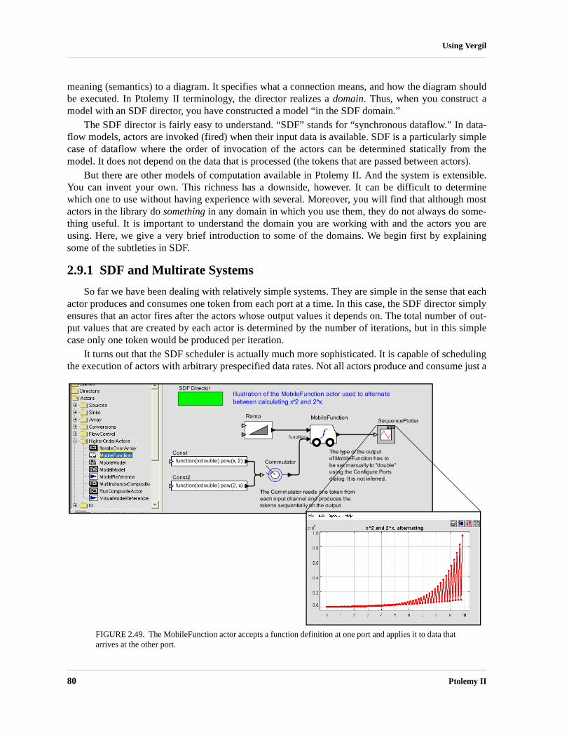
80 Ptolemy II
Using Vergil
meaning (semantics) to a diagram. It specifies what a connection means, and how the diagram shouldbe executed. In Ptolemy II terminology, the director realizes a domain. Thus, when you construct amodel with an SDF director, you have constructed a model “in the SDF domain.”
The SDF director is fairly easy to understand. “SDF” stands for “synchronous dataflow.” In data-flow models, actors are invoked (fired) when their input data is available. SDF is a particularly simplecase of dataflow where the order of invocation of the actors can be determined statically from themodel. It does not depend on the data that is processed (the tokens that are passed between actors).
But there are other models of computation available in Ptolemy II. And the system is extensible.You can invent your own. This richness has a downside, however. It can be difficult to determinewhich one to use without having experience with several. Moreover, you will find that although mostactors in the library do something in any domain in which you use them, they do not always do some-thing useful. It is important to understand the domain you are working with and the actors you areusing. Here, we give a very brief introduction to some of the domains. We begin first by explainingsome of the subtleties in SDF.
2.9.1 SDF and Multirate Systems
So far we have been dealing with relatively simple systems. They are simple in the sense that eachactor produces and consumes one token from each port at a time. In this case, the SDF director simplyensures that an actor fires after the actors whose output values it depends on. The total number of out-put values that are created by each actor is determined by the number of iterations, but in this simplecase only one token would be produced per iteration.
It turns out that the SDF scheduler is actually much more sophisticated. It is capable of schedulingthe execution of actors with arbitrary prespecified data rates. Not all actors produce and consume just a
FIGURE 2.49. The MobileFunction actor accepts a function definition at one port and applies it to data that arrives at the other port.

Heterogeneous Concurrent Modeling and Design 81
Using Vergil
single sample each time they are fired. Some require several input token before they can be fired, andproduce several tokens when they are fired.
One such actor is a spectral estimation actor. Figure 2.50 shows a system that computes the spec-trum of the same noisy sine wave that we constructed in figure 2.25. The Spectrum actor has a singleparameter, which gives the order of the FFT used to calculate the spectrum. Figure 2.51 shows the out-put of the model with order set to 8 and the number of iterations set to 1. Note that there are 256 out-put samples output from the Spectrum actor. This is because the Spectrum actor requires 2^8, or 256input samples to fire, and produces 2^8, or 256 output samples when it fires. Thus, one iteration of themodel produces 256 samples. The Spectrum actor makes this a multirate model, because the firingrates of the actors are not all identical.
It is common in SDF to construct models that require exactly one iteration to produce a usefulresult. In some multirate models, it can be complicated to determine how many firings of each actoroccur per iteration of the model. See the SDF chapter in volume 3 for details.
A second subtlety with SDF models is that if there is a feedback loop, as in figure 2.52, then theloop must have at least one instance of the SampleDelay actor in it (found in the FlowControl library,SequenceControl sublibrary). Without this actor, the loop will deadlock. The SampleDelay actor pro-duces initial tokens on its output, before the model begins firing. The initial tokens produced are givenby a the initialOutputs parameter, which specifies an array of tokens. These initial tokens enable down-stream actors and break the circular dependencies that would result otherwise from a feedback loop.
FIGURE 2.50. A multirate SDF model. The Spectrum actor requires 256 tokens to fire, so one iteration of this model results in 256 firings of Sinewave, Channel, and SequencePlotter, and one firing of Spectrum.
FIGURE 2.51. A single iteration of the SDF model in figure 2.50 produces 256 output tokens.

82 Ptolemy II
Using Vergil
A final issue to consider with the SDF domain is time. Notice that in all the examples above wehave suggested using the SequencePlotter actor, not the TimedPlotter actor, which is in Sinks library,TimedSinks sublibrary. This is because the SDF domain does not include in its semantics a notion oftime. Time does not advance as an SDF model executes, so the TimedPlotter actor would produce veryuninteresting results, where the horizontal axis value would always be zero. The SequencePlotter actoruses the index in the sequence for the horizontal axis. The first token received is plotted at horizontalposition 0, the second at 1, the third at 2, etc. The next domain we consider, DE, includes much stron-ger notion of time, and it is almost always more appropriate in the DE domain to use the TimedPlotteractor.
2.9.2 Data-Dependent Rates
Several domains generalize SDF to support data-dependent rates. The most mature of these is theprocess networks domain (PN), which associates with each actor its own thread of control. PSDF(parameterized SDF) and HDF (heterochronous dataflow) are more experimental, but are possiblymore efficient and formally analyzable than PN. See volume 3 for details about domains.
2.9.3 Discrete-Event Systems
In discrete-event (DE) systems, the connections between actors carry signals that consist of eventsplaced on a time line. Each event has both a value and a time stamp, where its time stamp is a double-precision floating-point number. This is different from dataflow, where a signal consists of a sequenceof tokens, and there is no time significance in the signal.
A DE model executes chronologically, processing the oldest events first. Time advances as eventsare processed. There is potential confusion, however, between model time, the time that evolves in themodel, and real time, the time that elapses in the real world while the model executes (also called wall-clock time). Model time may advance more rapidly than real time or more slowly. The DE director hasa parameter, synchronizeToRealTime, that, when set to true, attempts to synchronize the two notions oftime. It does this by delaying execution of the model, if necessary, allowing real time to catch up withmodel time.
Consider the DE model shown in figure 2.53. This model includes a PoissonClock actor, a Cur-rentTime actor, and a WallClockTime actor, all found in the Sources library, TimedSources sublibrary.The PoissonClock actor generates a sequence of events with random times, where the time betweenevents is exponentially distributed. Such an event sequence is known as a Poisson process. The valueof the events produced by the PoissonClock actor is a constant, but the value of that constant is ignoredin this model. Instead, these events trigger the CurrentTime and WallClockTime actors. The Current-Time actor outputs an event with the same time stamp as the input, but whose value is the current
FIGURE 2.52. An SDF model with a feedback loop must have at least one instance of the SampleDelay actor in it.

Heterogeneous Concurrent Modeling and Design 83
Using Vergil
model time (equal to the time stamp of the input). The WallClockTime actor produces an event with thesame time stamp as the input, but whose value is the current real time, in seconds since initialization ofthe model.
The plot in figure 2.53 shows an execution. Note that model time has advanced approximately 10seconds, but real time has advanced almost not at all. In this model, model time advances much morerapidly than real time. If you build this model, and set the synchronizeToRealTime parameter of thedirector to true, then you will find that the two plots coincide almost perfectly.
A significant subtlety in using the DE domain is in how simultaneous events are handled. Simulta-neous events are simply events with the same time stamp. We have stated that events are processed inchronological order, but if two events have the same time stamp, then there is some ambiguity. Whichone should be processed first? If the two events are on the same signal, then the answer is simple: pro-cess first the one that was produced first. However, if the two events are on different signals, then theanswer is not so clear.
Consider the model shown in figure 2.54, which produces a histogram of the interarrival times ofevents from the PoissonClock actor. In this model, we calculate the difference between the currentevent time and the previous event time, resulting in the plot that is shown in the figure. The Previousactor is a zero-delay actor, meaning that it produces an output with the same time stamp as the input(except on the first firing, where in this case it produces no output). Thus, when the PoissonClock actorproduces an output, there will be two simultaneous events, one at the input to the plus port of theAddSubtract actor, and one at the input of the Previous actor. Should the director fire the AddSubtractactor or the Previous actor? Either seems OK if it is to respect chronological order, but it seems intui-tive that the Previous actor should be fired first.
It is helpful to know how the AddSubtract actor works. When it fires, it adds at most one tokenfrom each channel of the plus port, and subtracts at most one token from each channel of the minus
FIGURE 2.53. Model time vs. real time (wall clock time).

84 Ptolemy II
Using Vergil
port. If the AddSubtract actor fires before the Previous actor, then the only available token will be theone on the plus port, and the expected subtraction will not occur. Intuitively, we would expect thedirector to invoke the Previous actor before the AddSubtract actor so that the subtraction occurs.
How does the director deliver on the intuition that the Previous actor should be fired first? Beforeexecuting the model, the DE director constructs a topological sort of the model. A topological sort issimply a list of the actors in data-precedence order. For the model in figure 2.54, there is only oneallowable topological sort:• PoissonClock, CurrentTime, Previous, AddSubtract, HistogramPlotterIn this list, AddSubtract is after Previous. So the when they have simultaneous events, the DE directorfires Previous first.
Thus, the DE director, by analyzing the structure of the model, usually delivers the intuitive behav-ior, where actors that produce data are fired before actors that consume their results, even in the pres-ence of simultaneous events.
There remains one key subtlety. If the model has a directed loop, then a topological sort is not pos-sible. In the DE domain, every feedback loop is required to have at least one actor in it that introducesa time delay, such as the TimedDelay actor, which can be found in the DomainSpecific library underDiscreteEvent (this library is shown on the left in figure 2.55). Consider for example the model shownin figure 2.55. That model has a Clock actor, which is set to produce events every 1.0 time units. Thoseevents trigger the Ramp actor, which produces outputs that start at 0 and increase by 1 on each firing.In this model, the output of the Ramp goes into an AddSubtract actor, which subtracts from the Rampoutput its own prior output delayed by one time unit. The result is shown in the plot in the figure.
Occasionally, you will need to put a TimedDelay actor in a feedback loop with a delay of 0.0. Thisis particularly true if you are building complex models that mix domains, and there is a delay inside acomposite actor that the DE director cannot recognize as a delay. The TimedDelay actor with a delay of
FIGURE 2.54. Histogram of interarrival times, illustrating handling of simultaneous events.

Heterogeneous Concurrent Modeling and Design 85
Using Vergil
0.0 can be thought of as a way to let the director know that there is a time delay in the preceding actor,without specifying the amount of the time delay.
2.9.4 Wireless and Sensor Network Systems
The wireless domain builds on the discrete event domain to support modeling of wireless and sen-sor network systems. In the wireless domain, channel models mediate communication between actors,and the visual syntax does not require wiring between components. See [11] and [12] for details.
2.9.5 Continuous-Time Systems
The continuous-time domain (CT) is another relatively mature domain with semantics consider-ably different from either DE or SDF. In CT, the signals sent along connections between actors are usu-ally continuous-time signals. A CT example is described above in section 2.2.3.
The CT domain can also handle discrete events. These events are usually related to a continuous-time signal, for example representing a zero-crossing of the continuous-time signal. The CT director isquite sophisticated in its handling of such mixed signal systems.
FIGURE 2.55. Discrete-event model with feedback, which requires a delay actor such as TimedDelay. Notice the library of domain-specific actors at the left.

86 Ptolemy II
Using Vergil
2.10 Hybrid Systems and Modal Models
Hybrid systems are models that combine continuous dynamics with discrete mode changes. Theyare created in Ptolemy II by creating a ModalModel, found in the HigherOrderActors library. We startby examining a pre-built modal model, and conclude by illustrating how to construct one. Modal mod-els can be constructed with other domains besides CT, but this section will concentrate on CT. Feel freeto examine other examples of modal models given in the quick tour, figure 2.3.
2.10.1 Examining a Pre-Built Model
Consider the bouncing ball example, which can be found under “Bouncing Ball” in figure 2.3 (inthe “Hybrid Systems” entry). The top-level contents of this model is shown in figure 2.56. It contains aBall Model, a TimedPlotter, and PeriodicSampler, and an Animate Ball composite actor. The BallModel is an instance of the ModalModel found in the HigherOrderActors library, but renamed. If youexecute the model, you should see a plot like that in the figure and a 3-D animation that is constructedusing the GR (graphics) domain. The continuous dynamics correspond to the times when the ball is inthe air, and the discrete events correspond to the times when the ball hits the surface and bounces.
If you invoke “Open Actor” on the Ball Model, you will see something like figure 2.57. Figure2.57 shows a state-machine editor, which has a slightly different toolbar and a significantly differentlibrary at the left. The circles in figure 2.57 are states, and the arcs between circles are transitionsbetween states. A modal model is one that has modes, which represent regimes of operation. Eachmode in a modal model is represented by a state in a finite-state machine.
The state machine in figure 2.57 has three states, named init, free, and stop. The init state is the ini-tial state, which is set as shown in figure 2.58. The free state represents the mode of operation wherethe ball is in free fall, and the stop state represents the mode where the ball has stopped bouncing.
FIGURE 2.56. Top level of the bouncing ball example.

Heterogeneous Concurrent Modeling and Design 87
Using Vergil
At any time during the execution of the model, the modal model is in one of these three states.When the model begins executing, it is in the init state. During the time a modal model is in a state, thebehavior of the modal model is specified by the refinement of the state. The refinement can be exam-ined by looking inside the state. As shown in figure 2.59, the init state has no refinement.
Consider the transition from init to free. It is labeled as follows:
FIGURE 2.57. Inside the Ball Model of figure 2.56.
FIGURE 2.58. The initial state of a state machine is set by right clicking on the background and specifying the state name.
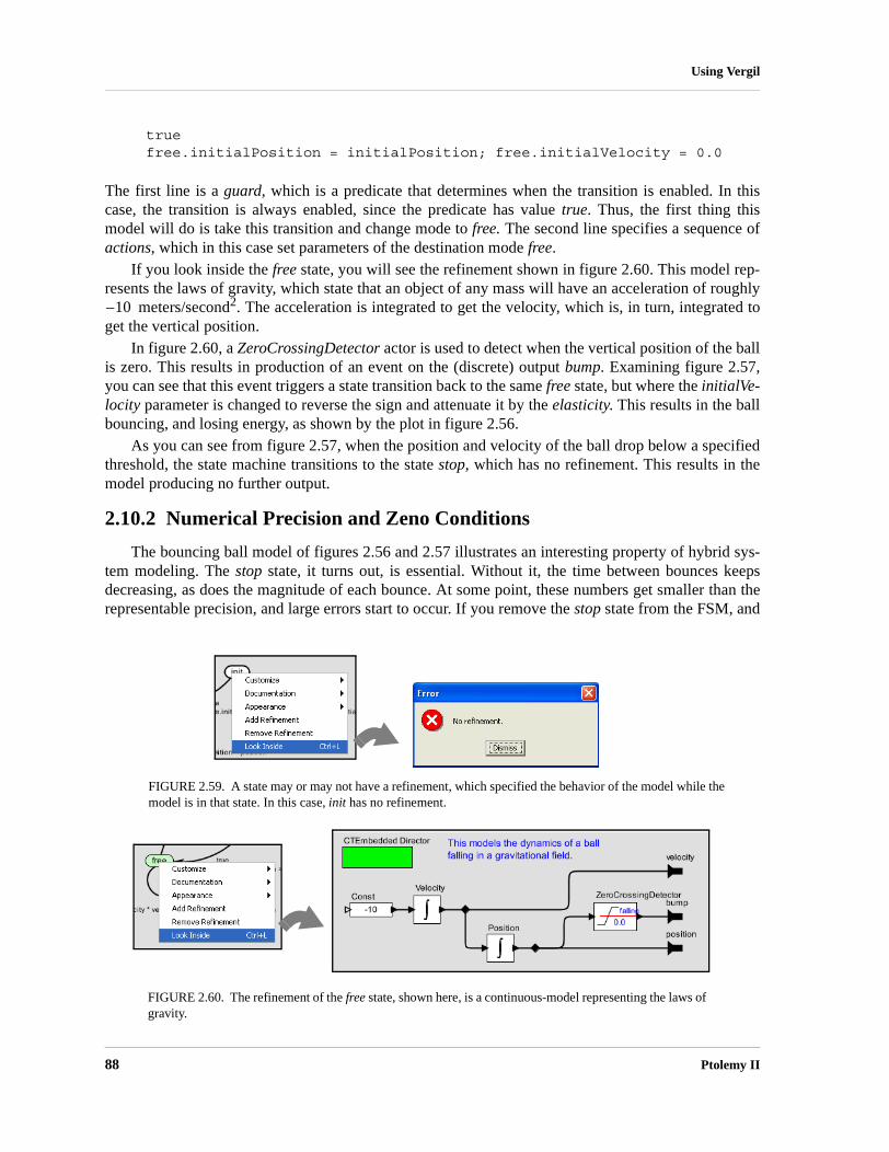
88 Ptolemy II
Using Vergil
truefree.initialPosition = initialPosition; free.initialVelocity = 0.0
The first line is a guard, which is a predicate that determines when the transition is enabled. In thiscase, the transition is always enabled, since the predicate has value true. Thus, the first thing thismodel will do is take this transition and change mode to free. The second line specifies a sequence ofactions, which in this case set parameters of the destination mode free.
If you look inside the free state, you will see the refinement shown in figure 2.60. This model rep-resents the laws of gravity, which state that an object of any mass will have an acceleration of roughly
meters/second2. The acceleration is integrated to get the velocity, which is, in turn, integrated toget the vertical position.
In figure 2.60, a ZeroCrossingDetector actor is used to detect when the vertical position of the ballis zero. This results in production of an event on the (discrete) output bump. Examining figure 2.57,you can see that this event triggers a state transition back to the same free state, but where the initialVe-locity parameter is changed to reverse the sign and attenuate it by the elasticity. This results in the ballbouncing, and losing energy, as shown by the plot in figure 2.56.
As you can see from figure 2.57, when the position and velocity of the ball drop below a specifiedthreshold, the state machine transitions to the state stop, which has no refinement. This results in themodel producing no further output.
2.10.2 Numerical Precision and Zeno Conditions
The bouncing ball model of figures 2.56 and 2.57 illustrates an interesting property of hybrid sys-tem modeling. The stop state, it turns out, is essential. Without it, the time between bounces keepsdecreasing, as does the magnitude of each bounce. At some point, these numbers get smaller than therepresentable precision, and large errors start to occur. If you remove the stop state from the FSM, and
FIGURE 2.59. A state may or may not have a refinement, which specified the behavior of the model while the model is in that state. In this case, init has no refinement.
FIGURE 2.60. The refinement of the free state, shown here, is a continuous-model representing the laws of gravity.
10–

Heterogeneous Concurrent Modeling and Design 89
Using Vergil
re-run the model, you get the result shown in figure 2.61. The ball, in effect, falls through the surfaceon which it is bouncing and then goes into a free-fall in the space below.
The error that occurs here illustrates some fundamental pitfalls with hybrid system modeling. Theevent detected by the ZeroCrossingDetector actor can be missed by the simulator. This actor workswith the solver to attempt to identify the precise point in time when the event occurs. It ensures that thesimulation includes a sample time at that time. However, when the numbers get small enough, numeri-cal errors take over, and the event is missed.
A related phenomenon is called the Zeno phenomenon. In the case of the bouncing ball, the timebetween bounces gets smaller as the simulation progresses. Since the simulator is attempting to captureevery bounce event with a time step, we could encounter the problem where the number of time stepsbecomes infinite over a finite time interval. This makes it impossible for time to advance. In fact, intheory, the bouncing ball example exhibits this Zeno phenomenon. However, numerical precisionerrors take over, since the simulator cannot possibly keep decreasing the magnitude of the time incre-ments.
The lesson is that some caution needs to be exercised when relying on the results of a simulation ofa hybrid system. Use your judgement.
2.10.3 Constructing Modal Models
A modal model is a component in a larger continuous-time (or other kind of) model. You can cre-ate a modal model by dragging one in from the HigherOrderActors library. By default, it has no ports.To make it useful, you will need to add ports. The mechanism for doing that is identical to adding portsto a composite model, and is explained in section 2.4.2. Figure 2.56 shows a top-level continuous-timemodel with a single modal model that has been renamed Ball Model. Three output ports have beenadded to that modal model, but only the top one is used. It gives the vertical distance of the ball fromthe surface on which it bounces.
If you create a new modal model by dragging it in from the HigherOrderActors library, create anoutput port and name it output, and then look inside, you will get an FSM editor like that shown in fig-ure 2.62. Note that the output port is (regrettably) located at the upper left, and is only partially visible.The annotation text suggests that you delete it once you no longer need it. You may want to move theport to a more reasonable location (where it is visible).
The output port that you created is in fact indicated in the state machine as being both an outputand input port. The reason for this is that guards in the state machine can refer to output values that are
FIGURE 2.61. Result of running the bouncing ball model without the stop state.

90 Ptolemy II
Using Vergil
produced on this port by refinements. In addition, the output actions of a transition can assign an out-put value to this port. Hence, the port is, in fact, both an output and input for the state machine.
To create a finite-state machine like that in figure 2.57, drag in states (white circles), or click on thestate icon in the toolbar. You can rename these states by right clicking on them and selecting “Custom-ize Name”. Choose names that are pertinent to your application. In figure 2.57, there is an init state forinitialization, a free state for when the ball is in the air, and a stop state for when the ball is no longerbouncing. You must specify the initial state of the FSM by right clicking on the background of theFSM Editor, selecting “Edit Parameters”, and specifying an initial state name, as shown in figure 2.58.In that figure, the initial state is named init.
Creating Transitions. To create transitions, you must hold the control button1 on the keyboard whileclicking and dragging from one state to the next (a transition can also go back to the same state). Thehandles on the transition can be used to customize its curvature and orientation. Double clicking on thetransition (or right clicking and selecting “Configure”) allows you to configure the transition. The dia-log for the transition from init to free is shown in figure 2.63. In that dialog, we see the following:• The guard expression is true, so this transition is always enabled. The transition will be taken as
soon as the model begins executing. A guard expression can be any boolean-valued expression that depends on the inputs, parameters, or even the outputs of any refinement of the current state (see below). Thus, this transition is used to initialize the model.
• The output actions are empty, meaning that when this transition is taken, no output is specified. This parameter can have a list of assignments of values to output ports, separated by semicolons. Those values will be assigned to output ports when the transition is taken.
• The set actions field contains the following statements:
1. Or the command button on a Macintosh computer.
FIGURE 2.62. Inside of a new modal model that has had a single output port added.
output port

Heterogeneous Concurrent Modeling and Design 91
Using Vergil
free.initialPosition = initialPosition; free.initialVelocity = 0.0
The “free” in these expressions refers to the mode refinement in the free state. Thus, free.initialPo-sition is a parameter of that mode refinement. Here, its value is assigned to the value of the param-eter initialPosition. The parameter free.initialVelocity is set to zero.
• The reset parameter is set to true, meaning that the destination mode refinement will be initialized when the transition is taken.
• The preemptive parameter is set to false. In this case, it makes no difference, since the init state has no refinement. Normally, if a transition out of a state is enabled and preemptive is true, then the transition will be taken without first executing the refinement. Thus, the refinement will not affect the outputs of the modal model.
A state may have several outgoing transitions. However, it is up to the model builder to ensure that atno time does more than one guard on these transitions evaluate to true. In other words, Ptolemy II doesnot allow nondeterministic state machines, and will throw an exception if it encounters one.
Creating Refinements. Both states and transitions can have refinements. To create a refinement, rightclick1 on the state or transition, and select “Add Refinement.” You will see a dialog like that in figure2.64. As shown in the figure, you will be offered the alternatives of a “Default Refinement” or a “StateMachine Refinement.” The first of these provides a block diagram model as the refinement. The sec-ond provides another finite state machine as the refinement. In the former case (the default), a blankrefinement model will open, as shown in the figure. As before, the output port will appear in an incon-venient location. You will almost certainly want to move it to a more convenient location. You willhave to create a director in the refinement. The modal model will not operate without a director in therefinement.
You can also create refinements for transitions, but these have somewhat different behavior. Theywill execute exactly once when the transition is taken. For this reason, only certain directors makesense in such refinements. The most commonly useful is the SDF director. Such refinements are typi-cally used to perform arithmetic computations that are too elaborate to be conveniently specified as anaction on the transition.
1. On a Macintosh, control-click.
FIGURE 2.63. Transition dialog for the transition from init to free in figure 2.57.

92 Ptolemy II
Using Vergil
Once you have created a refinement, you can look inside a state or transition. For the bouncing ballexample, the refinement of the free state is shown in figure 2.60. This model exhibits certain key prop-erties of refinements:• Refinements must contain directors. In this case, the CTEmbeddedDirector is used. When a con-
tinuous-time model is used inside a mode, this director must be used instead of the default CTDi-rector (see the CT domain documentation for details).
• The refinement has the same ports as the modal model, and can read input values and specify out-put values. When the state machine is in the state of which this is the refinement, this model will be executed to read the inputs and produce the outputs.
2.10.4 Execution Semantics
The behavior of a refinement is simple. When the modal model is executed, the followingsequence of events occurs:• For any transitions out of the current state for which preemptive is true, the guard is evaluated. If
exactly one such guard evaluates to true, then that transition is chosen. The output actions of the transition are executed, and the refinements of the transition (if any) are executed, followed by the set actions.
• If no preemptive transition evaluated to true, then the refinement of the current state, if there is one, is evaluated at the current time step.
• Once the refinement has been evaluated (and it has possibly updated its output values), the guard expressions on all the outgoing transitions of the current state are evaluated. If none is true, the execution is complete. If one is true, then that transition is taken. If more than one is true, then an exception is thrown (the state machine is nondeterministic). What it means for the transition to be “taken” is that its output actions are executed, its refinements (if any) are executed, and its set actions are executed.
• If reset is true on a transition that is taken, then the refinement of the destination mode (if there is one) is initialized.
There is a subtle distinction between the output actions and the set actions. The intent of these two
FIGURE 2.64. Adding a refinement to a state.
output port

Heterogeneous Concurrent Modeling and Design 93
Using Vergil
fields on the transition is that output actions are used to define the values of output ports, while setactions are used to define state variables in the refinements of the destination modes. The reason thatthese two actions are separated is that while solving a continuous-time system of equations, the solvermay speculatively execute models at certain time steps before it is sure what the next time step will be.The output actions make no permanent changes to the state of the system, and hence can be executedduring this speculative phase. The set actions, however, make permanent changes to the state variablesof the destination refinements, and hence are not executed during the speculative phase.
2.11 Using the Plotter
Several of the plots shown above have flaws that can be fixed using the features of the plotter. Forinstance, the plot shown in figure 2.51 has the default (uninformative) title, the axes are not labeled,and the horizontal axis ranges from 0 to 2551, because in one iteration, the Spectrum actor produces256 output tokens. These outputs represent frequency bins that range between and radians persecond.
The SequencePlotter actor has some pertinent parameters, shown in figure 2.65. The xInit parame-ter specifies the value to use on the horizontal axis for the first token. The xUnit parameter specifies thevalue to increment this by for each subsequent token. Setting these to “-PI” and “PI/128” respectivelyresults in the plot shown in figure 2.66.
This plot is better, but still missing useful information. To control more precisely the visual appear-ance of the plot, click on the second button from the right in the row of buttons at the top right of the
1. Hint: Notice the “x102” at the bottom right, which indicates that the label “2.5” stands for “250”.
π– π
FIGURE 2.65. Dialog for creating a refinement of a state.
FIGURE 2.66. Better labeled plot, where the horizontal axis now properly represents the frequency values.

94 Ptolemy II
Using Vergil
plot. This button brings up a format control window. It is shown in figure 2.67, filled in with valuesthat result in the plot shown in figure 2.68. Most of these are self-explanatory, but the following point-ers may be useful:• The grid is turned off to reduce clutter.• Titles and axis labels have been added.• The X range and Y range are determined by the fill button at the upper right of the plot.• Stem plots can be had by clicking on “Stems”• Individual tokens can be shown by clicking on “dots”• Connecting lines can be eliminated by deselecting “connect”• The X axis label has been changed to symbolically indicate multiples of PI/2. This is done by
entering the following in the X Ticks field:
-PI -3.14159, -PI/2 -1.570795, 0 0.0, PI/2 1.570795, PI 3.14159
The syntax in general is:
FIGURE 2.67. Format control window for a plot.
FIGURE 2.68. Still better labeled plot.

Heterogeneous Concurrent Modeling and Design 95
Using Vergil
label value, label value, ...
where the label is any string (enclosed in quotation marks if it includes spaces), and the value is a number.

96 Ptolemy II
Using Vergil

Heterogeneous Concurrent Modeling and Design 97
3 Expressions
Authors: Edward A. LeeXiaojun LiuSteve NeuendorfferNeil SmythYuhong Xiong
3.1 Introduction
In Ptolemy II, models specify computations by composing actors. Many computations, however,are awkward to specify this way. A common situation is where we wish to evaluate a simple algebraicexpression, such as “sin(2π (x-1)).” It is possible to express this computation by composing actors in ablock diagram, but it is far more convenient to give it textually.
The Ptolemy II expression language provides infrastructure for specifying algebraic expressionstextually and for evaluating them. The expression language is used to specify the values of parameters,guards and actions in state machines, and for the calculation performed by the Expression actor. Infact, the expression language is part of the generic infrastructure in Ptolemy II, and it can be used byprogrammers extending the Ptolemy II system. In this chapter, we describe how to use expressionsfrom the perspective of a user rather than a programmer.
3.1.1 Expression Evaluator
Vergil provides an interactive expression evaluator, which is accessed through the File:New menu.This operates like an interactive command shell, and is shown in figure 3.1. It supports a command his-tory. To access the previously entered expression, type the up arrow or Control-P. To go back, type thedown arrow or Control-N. The expression evaluator is useful for experimenting with expressions.

98 Ptolemy II
Expressions
3.2 Simple Arithmetic Expressions
3.2.1 Constants and Literals
The simplest expression is a constant, which can be given either by the symbolic name of the con-stant, or by a literal. By default, the symbolic names of constants supported are PI, pi, E, e, true, false,i, j, NaN, Infinity, PositiveInfinity, NegativeInfinity, MaxUnsignedByte, MinUnsignedByte, MaxInt,MinInt, MaxLong, MinLong, MaxDouble, MinDouble. For example,
PI/2.0
is a valid expression that refers to the symbolic name “PI” and the literal “2.0.” The constants i and jare the imaginary number with value equal to the square root of −1. The constant NaN is “not a num-ber,” which for example is the result of dividing 0.0/0.0. The constant Infinity is the result of dividing1.0/0.0. The constants that start with “Max” and “Min” are the maximum and minimum values fortheir corresponding types.
Numerical values without decimal points, such as “10” or “−3” are integers (type int). Numericalvalues with decimal points, such as “10.0” or “3.14159” are of type double. Numerical values withoutdecimal points followed by the character “l” (el) or “L” are of type long. Unsigned integers followedby “ub” or “UB” are of type unsignedByte, as in “5ub”. An unsignedByte has a value between 0 and255; note that it not quite the same as the Java byte, which has a value between -128 and 127.
Numbers of type int, long, or unsignedByte can be specified in decimal, octal, or hexadecimal.Numbers beginning with a leading “0” are octal numbers. Numbers beginning with a leading “0x” arehexadecimal numbers. For example, “012” and “0xA” are both equal to the integer 10.
A complex is defined by appending an “i” or a “j” to a double for the imaginary part. This gives apurely imaginary complex number which can then leverage the polymorphic operations in the Token
FIGURE 3.1. Expression evaluator, which is accessed through the File:New menu.

Heterogeneous Concurrent Modeling and Design 99
Expressions
classes to create a general complex number. Thus “2 + 3i” will result in the expected complex num-ber. You can optionally write this “2 + 3*i”.
Literal string constants are also supported. Anything between double quotes, “...”, is interpreted asa string constant. The following built-in string-valued constants are defined:
The value of these variables is the value of the Java virtual machine property, such as user.home. Theproperties user.dir and user.home are standard in Java. Their values are platform dependent; see thedocumentation for the java.lang.System.getProperties() method for details. Note that user.dir anduser.home are usually not readable in unsigned applets, in which case, attempts to use these variablesin an expression will result in an exception. Vergil will display all the Java properties if you invokeJVM Properties in the View menu of a Graph Editor.
The ptolemy.ptII.dir property is set automatically when Vergil or any other Ptolemy II executableis started up. You can also set it when you start a Ptolemy II process using the java command by a syn-tax like the following:
java -Dptolemy.ptII.dir=${PTII} classname
where classname is the full class name of a Java application.The constants() utility function returns a record with all the globally defined constants. If you open
the expression evaluator and invoke this function, you will see that its value is something like:
{CWD="C:\ptII\ptolemy\data\expr", E=2.718281828459, HOME="C:\Documents and Settings\eal", Infinity=Infinity, MaxDouble=1.7976931348623E308, MaxInt=2147483647, MaxLong=9223372036854775807L, MaxUnsignedByte=255ub, MinDouble=4.9E-324, MinInt=-2147483648, MinLong=-9223372036854775808L, MinUnsignedByte=0ub, NaN=NaN, NegativeInfinity=-Infinity, PI=3.1415926535898, PTII="c:\ptII", PositiveInfinity=Infinity, boolean=false, complex=0.0 + 0.0i, double=0.0, e=2.718281828459, false=false, fixedpoint=fix(0.0,2,1),
TABLE 1: String-valued constants defined in the expression language.
Variable name Meaning Property name Example under Windows
PTII The directory in which Ptolemy II is installed ptolemy.ptII.dir c:\tmp
HOME The user home directory user.home c:\Documents and Settings\you
CWD The current working directory user.dir c:\ptII
TMPDIR The temporary directory java.io.tmpdir c:\Documents and Set-tings\you\Local Settings\Temp
100 Ptolemy II
Expressions
general=present, i=0.0 + 1.0i, int=0, j=0.0 + 1.0i, long=0L, matrix=[], object=object(null),pi=3.1415926535898, scalar=present, string="", true=true, unknown=present, unsignedByte=0ub}
3.2.2 Variables
Expressions can contain identifiers that are references to variables within the scope of the expres-sion. For example,
PI*x/2.0
is valid if “x” is a variable in scope. In the expression evaluator, the variables that are in scope includethe built-in constants plus any assignments that have been previously made. For example,
>> x = pi/21.5707963267949>> sin(x)1.0>>
In the context of Ptolemy II models, the variables in scope include all parameters defined at the samelevel of the hierarchy or higher. So for example, if an actor has a parameter named “x” with value 1.0,then another parameter of the same actor can have an expression with value “PI*x/2.0”, which willevaluate to π /2.
Consider a parameter P in actor X which is in turn contained by composite actor Y. The scope of anexpression for P includes all the parameters contained by X and Y, plus those of the container of Y, itscontainer, etc. That is, the scope includes any parameters defined above in the hierarchy.
You can add parameters to actors (composite or not) by right clicking on the actor, selecting “Con-figure” and then clicking on “Add”, or by dragging in a parameter from the utilities library. Thus, youcan add variables to any scope, a capability that serves the same role as the “let” construct in manyfunctional programming languages.
Occasionally, it is desirable to access parameters that are not in scope. The expression languagesupports a limited syntax that permits access to certain variables out of scope. In particular, if in placeof a variable name x in an expression you write A::x, then instead of looking for x in scope, the inter-preter looks for a container named A in the scope and a parameter named x in A. This allows reachingdown one level in the hierarchy from either the current container or any of its containers.
3.2.3 Operators
The arithmetic operators are +, −, *, /, ^, and %. Most of these operators operate on most datatypes, including arrays, records, and matrices. The ^ operator computes “to the power of” or exponen-tiation where the exponent can only be an int or an unsignedByte.
The unsignedByte, int and long types can only represent integer numbers. Operations on thesetypes are integer operations, which can sometimes lead to unexpected results. For instance, 1/2 yields 0if 1 and 2 are integers, whereas 1.0/2.0 yields 0.5. The exponentiation operator ‘^’ when used withnegative exponents can similarly yield unexpected results. For example, 2^−1 is 0 because the result iscomputed as 1/(2^1).

Heterogeneous Concurrent Modeling and Design 101
Expressions
The % operation is a modulo or remainder operation. The result is the remainder after division.The sign of the result is the same as that of the dividend (the left argument). For example,
>> 3.0 % 2.01.0>> -3.0 % 2.0-1.0>> -3.0 % -2.0-1.0>> 3.0 % -2.01.0
The magnitude of the result is always less than the magnitude of the divisor (the right argument). Notethat when this operator is used on doubles, the result is not the same as that produced by the remain-der() function (see Table 5 on page 125). For instance,
>> remainder(-3.0, 2.0)1.0
The remainder() function calculates the IEEE 754 standard remainder operation. It uses a roundingdivision rather than a truncating division, and hence the sign can be positive or negative, depending oncomplicated rules (see page 118). For example, counter intuitively,
>> remainder(3.0, 2.0)-1.0
When an operator involves two distinct types, the expression language has to make a decisionabout which type to use to implement the operation. If one of the two types can be converted withoutloss into the other, then it will be. For instance, int can be converted losslessly to double, so 1.0/2 willresult in 2 being first converted to 2.0, so the result will be 0.5. Among the scalar types, unsignedBytecan be converted to anything else, int can be converted to double, and double can be converted to com-plex. Note that long cannot be converted to double without loss, nor vice versa, so an expression like2.0/2L yields the following error message:
Error evaluating expression "2.0/2L" in .Expression.evaluatorBecause:divide method not supported between ptolemy.data.DoubleToken '2.0' and ptolemy.data.LongToken '2L' because the types are incomparable.
All scalar types have limited precision and magnitude. As a result of this, arithmetic operations aresubject to underflow and overflow. • For double numbers, overflow results in the corresponding positive or negative infinity. Underflow
(i.e. the precision does not suffice to represent the result) will yield zero.• For integer types and fixedpoint, overflow results in wraparound. For instance, while the value of
MaxInt is 2147483647, the expression MaxInt + 1 yields −2147483648. Similarly, while Max-UnsignedByte has value 255ub, MaxUnsignedByte + 1ub has value 0ub. Note, however, that

102 Ptolemy II
Expressions
MaxUnsignedByte + 1 yields 256, which is an int, not an unsignedByte. This is because Max-UnsignedByte can be losslessly converted to an int, so the addition is int addition, not unsigned-Byte addition.
The bitwise operators are &, |, #, and ~. They operate on boolean, unsignedByte, int and long (but notfixedpoint, double or complex). The operator & is bitwise AND, ~ is bitwise NOT, and | is bitwise OR,and # is bitwise XOR (exclusive or, after MATLAB).
The relational operators are <, <=, >, >=, == and !=. They return type boolean. Note that theserelational operators check the values when possible, irrespective of type. So, for example,
1 == 1.0
returns true. If you wish to check for equality of both type and value, use the equals() method, as in
>> 1.equals(1.0)false
Boolean-valued expressions can be used to give conditional values. The syntax for this is
boolean ? value1 : value2
If the boolean is true, the value of the expression is value1; otherwise, it is value2.The logical boolean operators are &&, ||, !, & and |. They operate on type boolean and return type
boolean. The difference between logical && and logical & is that & evaluates all the operands regardlessof whether their value is now irrelevant. Similarly for logical || and |. This approach is borrowedfrom Java. Thus, for example, the expression “false && x” will evaluate to false irrespective ofwhether x is defined. On the other hand, “false & x” will throw an exception.
The << and >> operators performs arithmetic left and right shifts respectively. The >>> operatorperforms a logical right shift, which does not preserve the sign. They operate on unsignedByte, int, andlong.
3.2.4 Comments
In expressions, anything inside /*...*/ is ignored, so you can insert comments.
3.3 Uses of Expressions
3.3.1 Parameters
The values of most parameters of actors can be given as expressions1. The variables in the expres-sion refer to other parameters that are in scope, which are those contained by the same container orsome container above in the hierarchy. They can also reference variables in a scope-extending
1. The exceptions are parameters that are strictly string parameters, in which case the value of the parameter is the literal string, not the string interpreted as an expression, as for example the function parameter of the TrigFunction actor, which can take on only “sin,” “cos,” “tan”, “asin”, “acos”, and “atan” as values.

Heterogeneous Concurrent Modeling and Design 103
Expressions
attribute, which includes variables defining units, as explained below in section 3.10. Adding parame-ters to actors is straightforward, as explained in the previous chapter.
3.3.2 Port Parameters
It is possible to define a parameter that is also a port. Such a PortParameter provides a defaultvalue, which is specified like the value of any other parameter. When the corresponding port receivesdata, however, the default value is overridden with the value provided at the port. Thus, this objectfunctions like a parameter and a port. The current value of the PortParameter is accessed like that ofany other parameter. Its current value will be either the default or the value most recently received onthe port.
A PortParameter might be contained by an atomic actor or a composite actor. To put one in a com-posite actor, drag it into a model from the utilities library, as shown in figure 3.2. The resulting icon isactually a combination of two icons, one representing the port, and the other representing the parame-ter. These can be moved separately, but doing so might create confusion, so we recommend selectingboth by clicking and dragging over the pair and moving both together.
To be useful, a PortParameter has to be given a name (the default name, “portParameter,” is notvery compelling). To change the name, right click on the icon and select “Customize Name,” as shownin figure 3.2. In the figure, the name is set to “noiseLevel.” Then set the default value by either doubleclicking or selecting “Configure.” In the figure, the default value is set to 10.0.
An example of a library actor that uses a PortParameter is the Sinewave actor, which is found inthe sources library in Vergil. It is shown in figure 3.3. If you double click on this actor, you can set thedefault values for frequency and phase. But both of these values can also be set by the correspondingports, which are shown with grey fill.
FIGURE 3.2. A portParameter is both a port and a parameter. To use it in a composite actor, drag it into the actor, change its name to something meaningful, and set its default value.
customize the name:

104 Ptolemy II
Expressions
3.3.3 String Parameters
Some parameters have values that are always strings of characters. Such parameters support a sim-ple string substitution mechanism where the value of the string can reference other parameters in scopeby name using the syntax $name, where name is the name of the parameter in scope. For example, theStringCompare actor in figure 3.4 has as the value of firstString “The answer is $PI”. This referencesthe built-in constant PI. The value of secondString is “The answer is 3.1415926535898”. As shown inthe figure, these two strings are deemed to be equal because $PI is replaced with the value of PI.
3.3.4 Expression Actor
The Expression actor is a particularly useful actor found in the math library. By default, it has oneoutput and no inputs, as shown in Figure 3.5(a). The first step in using it is to add ports, as shown in (b)and (c), resulting in a new icon as shown in (d). Note: In (c) when you click on Add, you will beprompted for a Name (pick one) and a Class. Leave the Class entry blank and click OK. You then spec-ify an expression using the port names, as shown in (e), resulting in the icon shown in (f).
FIGURE 3.3. Sinewave actor, showing its port parameters, and their use at the lower level of the hierarchy.

Heterogeneous Concurrent Modeling and Design 105
Expressions
3.3.5 State Machines
Expressions give the guards for state transitions, as well as the values used in actions that produceoutputs and actions that set values of parameters in the refinements of destination states. This mecha-nism was explained in the previous chapter.
FIGURE 3.4. String parameters are indicated in the parameter editor boxes by a light blue background. A string parameter can include references to variables in scope with $name, where name is the name of the variable. In this example, the built-in constant $PI is referenced by name in the first
FIGURE 3.5. Illustration of the Expression actor.
(a)
(b)
(c)
(d)
(e) (f)

106 Ptolemy II
Expressions
3.4 Composite Data Types
3.4.1 Arrays
Arrays are specified with curly brackets, e.g., “{1, 2, 3}” is an array of int, while “{"x","y", "z"}” is an array of string. The types are denoted “{int}” and “{string}” respectively. Anarray is an ordered list of tokens of any type, with the only constraint being that the elements all havethe same type. If an array is given with mixed types, the expression evaluator will attempt to losslesslyconvert the elements to a common type. Thus, for example,
{1, 2.3}
has value
{1.0, 2.3}
Its type is {double}. The common type might be scalar, which is a union type (a type that can containmultiple distinct types). For example,
{1, 2.3, true}
has value
{1, 2.3, true}
The value is unchanged, although the type of the array is now {scalar}.The elements of the array can be given by expressions, as in the example “{2*pi, 3*pi}.”
Arrays can be nested; for example, “{{1, 2}, {3, 4, 5}}” is an array of arrays of integers. Theelements of an array can be accessed as follows:
>> {1.0, 2.3}(1)2.3
which yields 2.3. Note that indexing begins at 0. Of course, if name is the name of a variable in scopewhose value is an array, then its elements may be accessed similarly, as shown in this example:
>> x = {1.0, 2.3}{1.0, 2.3}>> x(0)1.0

Heterogeneous Concurrent Modeling and Design 107
Expressions
Arithmetic operations on arrays are carried out element-by-element, as shown by the followingexamples:
>> {1, 2}*{2, 2}{2, 4}>> {1, 2}+{2, 2}{3, 4}>> {1, 2}-{2, 2}{-1, 0}>> {1, 2}^2{1, 4}>> {1, 2}%{2, 2}{1, 0}
Addition, subtraction, multiplication, division, and modulo of arrays by scalars is also supported,as in the following examples:
>> {1.0, 2.0} / 2.0{0.5, 1.0}>> 1.0 / {2.0, 4.0}{0.5, 0.25}>> 3 *{2, 3}{6, 9}>> 12 / {3, 4}{4, 3}
Arrays of length 1 are equivalent to scalars, as illustrated below:
>> {1.0, 2.0} / {2.0}{0.5, 1.0}>> {1.0} / {2.0, 4.0}{0.5, 0.25}>> {3} * {2, 3}{6, 9}>> {12} / {3, 4}{4, 3}
A significant subtlety arises when using nested arrays. Note the following example
>> {{1.0, 2.0}, {3.0, 1.0}} / {0.5, 2.0}{{2.0, 4.0}, {1.5, 0.5}}
In this example, the left argument of the divide is an array with two elements, and the right argument isalso an array with two elements. The divide is thus elementwise. However, each division is the divi-sion of an array by a scalar.

108 Ptolemy II
Expressions
An array can be checked for equality with another array as follows:
>> {1, 2}=={2, 2}false>> {1, 2}!={2, 2}true
For other comparisons of arrays, use the compare() function (see Table 5 on page 125). As with sca-lars, testing for equality using the == or != operators tests the values, independent of type. For exam-ple,
>> {1, 2}=={1.0, 2.0}true
You can extract a subarray by invoking the subarray() method as follows:
>> {1, 2, 3, 4}.subarray(2, 2){3, 4}
The first argument is the starting index of the subarray, and the second argument is the length.You can also extract non-contiguous elements from an array using the extract() method. This
method has two forms. The first form takes a boolean array of the same length as the original arraywhich indicates which elements to extract, as in the following example:
>> {"red","green","blue"}.extract({true,false,true}){"red", "blue"}
The second form takes an array of integers giving the indices to extract, as in the following example:
>> {"red","green","blue"}.extract({2,0,1,1}){"blue", "red", "green", "green"}
3.4.2 Matrices
In Ptolemy II, arrays are ordered sets of tokens. Ptolemy II also supports matrices, which are morespecialized than arrays. They contain only certain primitive types, currently boolean, complex, double,fixedpoint, int, and long. Currently unsignedByte matrices are not supported. Matrices cannot containarbitrary tokens, so they cannot, for example, contain matrices. They are intended for data intensivecomputations.
Matrices are specified with square brackets, using commas to separate row elements and semico-lons to separate rows. E.g., “[1, 2, 3; 4, 5, 5+1]” gives a two by three integer matrix (2 rows and 3 col-umns). Note that an array or matrix element can be given by an expression. A row vector can be givenas “[1, 2, 3]” and a column vector as “[1; 2; 3]”. Some MATLAB-style array constructors are sup-ported. For example, “[1:2:9]” gives an array of odd numbers from 1 to 9, and is equivalent to “[1, 3, 5,
Heterogeneous Concurrent Modeling and Design 109
Expressions
7, 9].” Similarly, “[1:2:9; 2:2:10]” is equivalent to “[1, 3, 5, 7, 9; 2, 4, 6, 8, 10].” In the syntax“[p:q:r]”, p is the first element, q is the step between elements, and r is an upper bound on the last ele-ment. That is, the matrix will not contain an element larger than r. If a matrix with mixed types is spec-ified, then the elements will be converted to a common type, if possible. Thus, for example, “[1.0, 1]”is equivalent to “[1.0, 1.0],” but “[1.0, 1L]” is illegal (because there is no common type to which bothelements can be converted losslessly).
Reference to elements of matrices have the form “matrix(n, m)” or “name(n, m)” where name isthe name of a matrix variable in scope, n is the row index, and m is the column index. Index numbersstart with zero, as in Java, not 1, as in MATLAB. For example,
>> [1, 2; 3, 4](0,0)1>> a = [1, 2; 3, 4][1, 2; 3, 4]>> a(1,1)4
Matrix multiplication works as expected. For example, as seen in the expression evaluator (see fig-ure 3.1),
>> [1, 2; 3, 4]*[2, 2; 2, 2][6, 6; 14, 14]
Of course, if the dimensions of the matrix don’t match, then you will get an error message. To do ele-ment wise multiplication, use the multipyElements() function (see Table 6 on page 127). Matrix addi-tion and subtraction are element wise, as expected, but the division operator is not supported. Elementwise division can be accomplished with the divideElements() function, and multiplication by a matrixinverse can be accomplished using the inverse() function (see Table 6 on page 127). A matrix can beraised to an int or unsignedByte power, which is equivalent to multiplying it by itself some number oftimes. For instance,
>> [3, 0; 0, 3]^3[27, 0; 0, 27]
A matrix can also be multiplied or divided by a scalar, as follows:
>> [3, 0; 0, 3]*3[9, 0; 0, 9]
A matrix can be added to a scalar. It can also be subtracted from a scalar, or have a scalar subtractedfrom it. For instance,
>> 1-[3, 0; 0, 3][-2, 1; 1, -2]

110 Ptolemy II
Expressions
A matrix can be checked for equality with another matrix as follows:
>> [3, 0; 0, 3]!=[3, 0; 0, 6]true>> [3, 0; 0, 3]==[3, 0; 0, 3]true
For other comparisons of matrices, use the compare() function (see Table 5 on page 125). As with sca-lars, testing for equality using the == or != operators tests the values, independent of type. For exam-ple,
>> [1, 2]==[1.0, 2.0]true
To get type-specific equality tests, use the equals() method, as in the following examples:
>> [1, 2].equals([1.0, 2.0])false>> [1.0, 2.0].equals([1.0, 2.0])true>>
3.4.3 Records
A record token is a composite type containing named fields, where each field has a value. Thevalue of each field can have a distinct type. Records are delimited by curly braces, with each fieldgiven a name. For example, “{a=1, b="foo"}” is a record with two fields, named “a” and “b”, withvalues 1 (an integer) and “foo” (a string), respectively. The value of a field can be an arbitrary expres-sion, and records can be nested (a field of a record token may be a record token).
Fields may be accessed using the period operator. For example,
{a=1,b=2}.a
yields 1. You can optionally write this as if it were a method call:
{a=1,b=2}.a()
The arithmetic operators +, −, *, /, and % can be applied to records. If the records do not have identicalfields, then the operator is applied only to the fields that match, and the result contains only the fieldsthat match. Thus, for example,
{foodCost=40, hotelCost=100} + {foodCost=20, taxiCost=20}
yields the result
{foodCost=60}

Heterogeneous Concurrent Modeling and Design 111
Expressions
You can think of an operation as a set intersection, where the operation specifies how to merge the val-ues of the intersecting fields. You can also form an intersection without applying an operation. In thiscase, using the intersect() function, you form a record that has only the common fields of two specifiedrecords, with the values taken from the first record. For example,
>> intersect({a=1, c=2}, {a=3, b=4}){a=1}
Records can be joined (think of a set union) without any operation being applied by using themerge() function. This function takes two arguments, both of which are record tokens. If the tworecord tokens have common fields, then the field value from the first record is used. For example,
merge({a=1, b=2}, {a=3, c=3})
yields the result {a=1, b=2, c=3}. Records can be compared, as in the following examples:
>> {a=1, b=2}!={a=1, b=2}false>> {a=1, b=2}!={a=1, c=2}true
Note that two records are equal only if they have the same field labels and the values match. As withscalars, the values match irrespective of type. For example:
>> {a=1, b=2}=={a=1.0, b=2.0+0.0i}true
The order of the fields is irrelevant. Hence
>> {a=1, b=2}=={b=2, a=1}true
Moreover, record fields are reported in alphabetical order, irrespective of the order in which they aredefined. For example,
>> {b=2, a=1}{a=1, b=2}
To get type-specific equality tests, use the equals() method, as in the following examples:
>> {a=1, b=2}.equals({a=1.0, b=2.0+0.0i})false>> {a=1, b=2}.equals({b=2, a=1})true>>

112 Ptolemy II
Expressions
3.5 Invoking Methods
Every element and subexpression in an expression represents an instance of the Token class inPtolemy II (or more likely, a class derived from Token). The expression language supports invocationof any method of a given token, as long as the arguments of the method are of type Token and thereturn type is Token (or a class derived from Token, or something that the expression parser can easilyconvert to a token, such as a string, double, int, etc.). The syntax for this is (token).methodName(args),where methodName is the name of the method and args is a comma-separated set of arguments. Eachargument can itself be an expression. Note that the parentheses around the token are not required, butmight be useful for clarity. As an example, the ArrayToken and RecordToken classes have a length()method, illustrated by the following examples:
{1, 2, 3}.length(){a=1, b=2, c=3}.length()
each of which returns the integer 3.The MatrixToken classes have three particularly useful methods, illustrated in the following exam-
ples:
[1, 2; 3, 4; 5, 6].getRowCount()
which returns 3, and
[1, 2; 3, 4; 5, 6].getColumnCount()
which returns 2, and
[1, 2; 3, 4; 5, 6].toArray()
which returns {1, 2, 3, 4, 5, 6}. The latter function can be particularly useful for creating arrays usingMATLAB-style syntax. For example, to obtain an array with the integers from 1 to 100, you can enter:
[1:1:100].toArray()
3.6 Defining Functions
The expression language supports definition of functions. The syntax is:
function(arg1:Type, arg2:Type...) function body
where “function” is the keyword for defining a function. The type of an argument can be left unspeci-fied, in which case the expression language will attempt to infer it. The function body gives an expres-sion that defines the return value of the function. The return type is always inferred based on the

Heterogeneous Concurrent Modeling and Design 113
Expressions
argument type and the expression. For example:
function(x:double) x*5.0
defines a function that takes a double argument, multiplies it by 5.0, and returns a double. The returnvalue of the above expression is the function itself. Thus, for example, the expression evaluator yields:
>> function(x:double) x*5.0(function(x:double) (x*5.0))>>
To apply the function to an argument, simply do
>> (function(x:double) x*5.0) (10.0)50.0>>
Alternatively, in the expression evaluator, you can assign the function to a variable, and then use thevariable name to apply the function. For example,
>> f = function(x:double) x*5.0(function(x:double) (x*5.0))>> f(10)50.0>>
Functions can be passed as arguments to certain “higher-order functions” that have been defined(see table Table 9 on page 131). For example, the iterate() function takes three arguments, a function,an integer, and an initial value to which to apply the function. It applies the function first to the initialvalue, then to the result of the application, then to that result, collecting the results into an array whoselength is given by the second argument. For example, to get an array whose values are multiples of 3,try
>> iterate(function(x:int) x+3, 5, 0){0, 3, 6, 9, 12}
The function given as an argument simply adds three to its argument. The result is the specified initialvalue (0) followed by the result of applying the function once to that initial value, then twice, thenthree times, etc.
Another useful higher-order function is the map() function. This one takes a function and an arrayas arguments, and simply applies the function to each element of the array to construct a result array.For example,
>> map(function(x:int) x+3, {0, 2, 3}){3, 5, 6}

114 Ptolemy II
Expressions
A typical use of functions in a Ptolemy II model is to define a parameter in a model whose value isa function. Suppose that the parameter named “f” has value “function(x:double) x*5.0”. Thenwithin the scope of that parameter, the expression “f(10.0)” will yield result 50.0.
Functions can also be passed along connections in a Ptolemy II model. Consider the model shownin figure 3.6. In that example, the Const actor defines a function that simply squares the argument. Itsoutput, therefore, is a token with type function. That token is fed to the “f” input of the Expressionactor. The expression uses this function by applying it to the token provided on the “y” input. Thattoken, in turn, is supplied by the Ramp actor, so the result is the curve shown in the plot on the right.
A more elaborate use is shown in figure 3.7. In that example, the Const actor produces a function,which is then used by the Expression actor to create new function, which is then used by Expression2to perform a calculation. The calculation performed here adds the output of the Ramp to the square ofthe output of the Ramp.
FIGURE 3.6. Example of a function being passed from one actor to another.
FIGURE 3.7. More elaborate example with functions passed between actors.
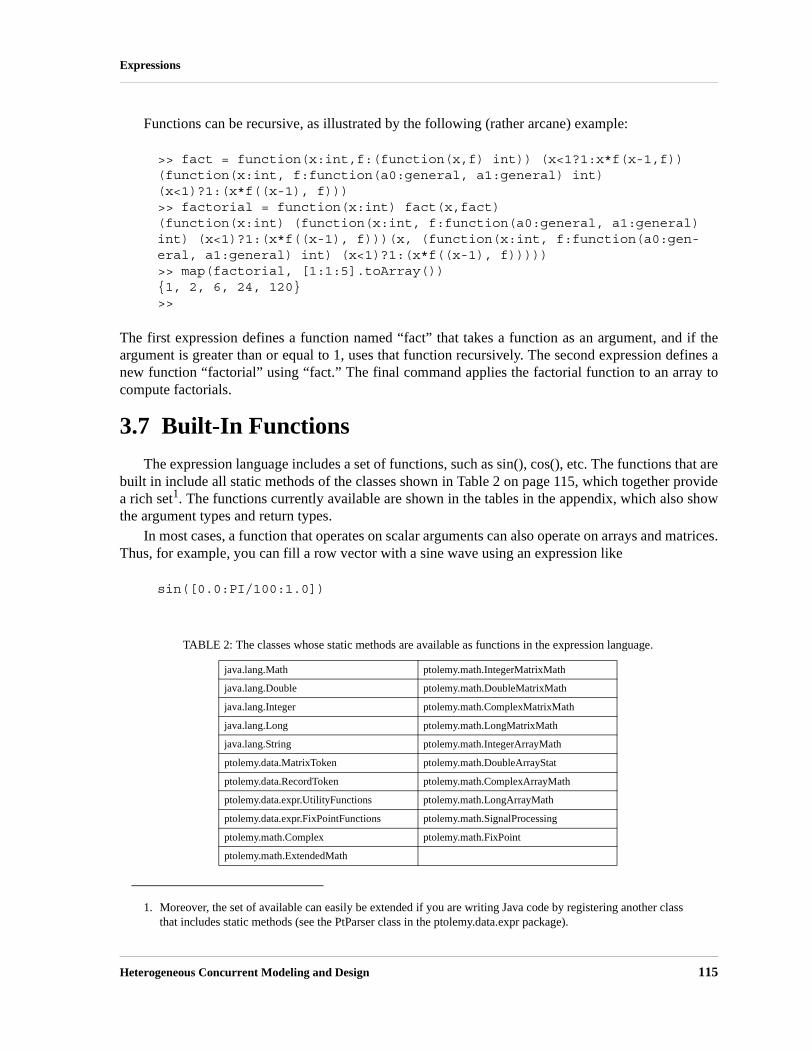
Heterogeneous Concurrent Modeling and Design 115
Expressions
Functions can be recursive, as illustrated by the following (rather arcane) example:
>> fact = function(x:int,f:(function(x,f) int)) (x<1?1:x*f(x-1,f))(function(x:int, f:function(a0:general, a1:general) int) (x<1)?1:(x*f((x-1), f)))>> factorial = function(x:int) fact(x,fact)(function(x:int) (function(x:int, f:function(a0:general, a1:general) int) (x<1)?1:(x*f((x-1), f)))(x, (function(x:int, f:function(a0:gen-eral, a1:general) int) (x<1)?1:(x*f((x-1), f)))))>> map(factorial, [1:1:5].toArray()){1, 2, 6, 24, 120}>>
The first expression defines a function named “fact” that takes a function as an argument, and if theargument is greater than or equal to 1, uses that function recursively. The second expression defines anew function “factorial” using “fact.” The final command applies the factorial function to an array tocompute factorials.
3.7 Built-In Functions
The expression language includes a set of functions, such as sin(), cos(), etc. The functions that arebuilt in include all static methods of the classes shown in Table 2 on page 115, which together providea rich set1. The functions currently available are shown in the tables in the appendix, which also showthe argument types and return types.
In most cases, a function that operates on scalar arguments can also operate on arrays and matrices.Thus, for example, you can fill a row vector with a sine wave using an expression like
sin([0.0:PI/100:1.0])
1. Moreover, the set of available can easily be extended if you are writing Java code by registering another class that includes static methods (see the PtParser class in the ptolemy.data.expr package).
TABLE 2: The classes whose static methods are available as functions in the expression language.
java.lang.Math ptolemy.math.IntegerMatrixMath
java.lang.Double ptolemy.math.DoubleMatrixMath
java.lang.Integer ptolemy.math.ComplexMatrixMath
java.lang.Long ptolemy.math.LongMatrixMath
java.lang.String ptolemy.math.IntegerArrayMath
ptolemy.data.MatrixToken ptolemy.math.DoubleArrayStat
ptolemy.data.RecordToken ptolemy.math.ComplexArrayMath
ptolemy.data.expr.UtilityFunctions ptolemy.math.LongArrayMath
ptolemy.data.expr.FixPointFunctions ptolemy.math.SignalProcessing
ptolemy.math.Complex ptolemy.math.FixPoint
ptolemy.math.ExtendedMath

116 Ptolemy II
Expressions
Or you can construct an array as follows,
sin({0.0, 0.1, 0.2, 0.3})
Functions that operate on type double will also generally operate on int or unsignedByte, because thesecan be losslessly converted to double, but not generally on long or complex.
Tables of available functions are shown in the appendix. For example, Table 4 on page 124 showstrigonometric functions. Note that these operate on double or complex, and hence on int and unsigned-Byte, which can be losslessly converted to double. The result will always be double. For example,
>> cos(0)1.0
These functions will also operate on matrices and arrays, in addition to the scalar types shown in thetable, as illustrated above. The result will be a matrix or array of the same size as the argument, butalways containing elements of type double
Table 5 on page 125 shows other arithmetic functions beyond the trigonometric functions. As withthe trigonometric functions, those that indicate that they operate on double will also work on int andunsignedByte, and unless they indicate otherwise, they will return whatever they return when the argu-ment is double. Those functions in the table that take scalar arguments will also operate on matricesand arrays. For example, since the table indicates that the max() function can take int, int as arguments,then by implication, it can also take {int}, {int}. For example,
>> max({1, 2}, {2, 1}){2, 2}
Notice that the table also indicates that max() can take {int} as an argument. E.g.
>> max({1, 2, 3})3
In the former case, the function is applied pointwise to the two arguments. In the latter case, thereturned value is the maximum over all the contents of the single argument.
Table 6 shows functions that only work with matrices, arrays, or records (that is, there is no corre-sponding scalar operation). Recall that most functions that operate on scalars will also operate onarrays and matricesTable 7 shows utility functions for evaluating expressions given as strings or repre-senting numbers as strings. Of these, the eval() function is the most flexible (see page 117).
A few of the functions have sufficiently subtle properties that they require further explanation.That explanation is here.

Heterogeneous Concurrent Modeling and Design 117
Expressions
eval() and traceEvaluation()
The built-in function eval() will evaluate a string as an expression in the expression language. Forexample,
eval("[1.0, 2.0; 3.0, 4.0]")
will return a matrix of doubles. The following combination can be used to read parameters from a file:
eval(readFile("filename"))
where the filename can be relative to the current working directory (where Ptolemy II was started, asreported by the property user.dir), the user’s home directory (as reported by the property user.home), orthe classpath, which includes the directory tree in which Ptolemy II is installed.
Note that if eval() is used in an Expression actor, then it will be impossible for the type system toinfer any more specific output type than general. If you need the output type to be more specific, thenyou will need to cast the result of eval(). For example, to force it to type double:
>> cast(double, eval("pi/2"))1.5707963267949
The traceEvaluation() function evaluates an expression given as a string, much like eval(), but insteadof reporting the result, reports exactly how the expression was evaluated. This can be used to debugexpressions, particularly when the expression language is extended by users.
random(), gaussian()
The functions random() and gaussian() shown in Table 5 on page 125 return one or more randomnumbers. With the minimum number of arguments (zero or two, respectively), they return a singlenumber. With one additional argument, they return an array of the specified length. With a secondadditional argument, they return a matrix with the specified number of rows and columns.
There is a key subtlety when using these functions in Ptolemy II. In particular, they are evaluatedonly when the expression within which they appear is evaluated. The result of the expression may beused repeatedly without re-evaluating the expression. Thus, for example, if the value parameter of theConst actor is set to “random()”, then its output will be a random constant, i.e., it will not change oneach firing. The output will change, however, on successive runs of the model. In contrast, if this isused in an Expression actor, then each firing triggers an evaluation of the expression, and consequentlywill result in a new random number.
property()
The property() function accesses system properties by name. Some possibly useful system proper-ties are:• ptolemy.ptII.dir: The directory in which Ptolemy II is installed.• ptolemy.ptII.dirAsURL: The directory in which Ptolemy II is installed, but represented as a URL.• user.dir: The current working directory, which is usually the directory in which the current execut-
able was started.

118 Ptolemy II
Expressions
remainder()
This function computes the remainder operation on two arguments as prescribed by the IEEE 754standard, which is not the same as the modulo operation computed by the % operator. The result ofremainder(x, y) is , where is the integer closest to the exact value of . If two integersare equally close, then is the integer that is even. This yields results that may be surprising, as indi-cated by the following examples:
>> remainder(1,2)1.0>> remainder(3,2)-1.0
Compare this to
>> 3%21
which is different in two ways. The result numerically different and is of type int, whereas remain-der() always yields a result of type double. The remainder() function is implemented by thejava.lang.Math class, which calls it IEEEremainder(). The documentation for that class gives thefollowing special cases:• If either argument is NaN, or the first argument is infinite, or the second argument is positive zero
or negative zero, then the result is NaN. • If the first argument is finite and the second argument is infinite, then the result is the same as the
first argument.
DCT() and IDCT()
The DCT function can take one, two, or three arguments. In all three cases, the first argument is anarray of length and the DCT returns an
(4)
for from 0 to , where is the size of the specified array and is the size of the DCT. If only
one argument is given, then is set to equal the next power of two larger than . If a second argu-
ment is given, then its value is the order of the DCT, and the size of the DCT is . If a third argu-
x yn– n x/yn
N 0>
Xk sk xn 2n 1+( )kπ
2D-------⎝ ⎠
⎛ ⎞cos
n 0=
N 1–
∑=
k D 1– N D
D N
2order

Heterogeneous Concurrent Modeling and Design 119
Expressions
ment is given, then it specifies the scaling factors according to the following table:
The default, if a third argument is not given, is “Normalized.”The IDCT function is similar, and can also take one, two, or three arguments. The formula in this
case is
. (5)
3.8 Nil Tokens
Null or missing tokens are common in analytical systems like R and SAS where they are used tohandle sparsely populated data sources. In database parlance, missing tokens are sometimes callednull tokens. Since null is a Java keyword, we use the term "nil". Nil tokens are useful for analyzingreal world data such as temperature where the value was not measured during every interval. In princi-ple, an as yet unimplemented function such as average() method could properly handle nil tokens -when the average() method sees a nil token, it should be ignored. Note that this can lead to uncertainty.For example, if average() is expecting 30 values and 29 of them are nil, then the average will not bevery accurate.
If an operation such as add(), divide(), modulo(), multiply(), one(), subtract(), zero() or their corre-sponding “reverse” operations includes a nil token, then the output is nil. If one of the arguments forisCloseTo() or isEqualTo() is nil, then the method returns false. Methods that return a nil token return anil token with a specific type so that type safety is preserved. The following tokens have NIL valuesdefined: ArrayType, BooleanToken, ComplexToken, DoubleToken, IntToken, LongToken, StringTo-ken, Token, UnsignedByteToken. There is no nil token for the various matrix tokens because theunderlying matrices are java native type matrices that do not support nil.
The expression language defines a constant named nil that refers to the Token.NIL field. Thecast() expression language function can be used to generate references to the NIL fields of the otherclasses. For example, “cast(int, nil)” will return a reference to the IntToken.NIL field.
TABLE 3: Normalization options for the DCT function
Name Third argument Normalization
Normalized 0
Unnormalized 1
Orthonormal 2
sk
sk1/ 2; k = 0
1 otherwise;⎩⎨⎧
=
sk 1=
sk1/ D; k = 0
2/D otherwise;⎩⎪⎨⎪⎧
=
xn skXk 2n 1+( )kπ
2D-------⎝ ⎠
⎛ ⎞cos
k 0=
N 1–
∑=

120 Ptolemy II
Expressions
3.9 Fixed Point Numbers
Ptolemy II includes a preliminary fixed point data type. We represent a fixed point value in theexpression language using the following format:
fix(value, totalBits, integerBits)
Thus, a fixed point value of 5.375 that uses 8 bit precision of which 4 bits are used to represent the(signed) integer part can be represented as:
fix(5.375, 8, 4)
The value can also be a matrix of doubles. The values are rounded, yielding the nearest value repre-sentable with the specified precision. If the value to represent is out of range, then it is saturated, mean-ing that the maximum or minimum fixed point value is returned, depending on the sign of the specifiedvalue. For example,
fix(5.375, 8, 3)
will yield 3.968758, the maximum value possible with the (8/3) precision.In addition to the fix() function, the expression language offers a quantize() function. The argu-
ments are the same as those of the fix() function, but the return type is a DoubleToken or DoubleMa-trixToken instead of a FixToken or FixMatrixToken. This function can therefore be used to quantizedouble-precision values without ever explicitly working with the fixed-point representation.
To make the FixToken accessible within the expression language, the following functions areavailable: • To create a single FixPoint Token using the expression language:
fix(5.34, 10, 4)
This will create a FixToken. In this case, we try to fit the number 5.34 into a 10 bit representation with 4 bits used in the integer part. This may lead to quantization errors. By default the round quantizer is used.
• To create a Matrix with FixPoint values using the expression language:fix([ -.040609, -.001628, .17853 ], 10, 2)
This will create a FixMatrixToken with 1 row and 3 columns, in which each element is a FixPoint value with precision(10/2). The resulting FixMatrixToken will try to fit each element of the given double matrix into a 10 bit representation with 2 bits used for the integer part. By default the round quantizer is used.
• To create a single DoubleToken, which is the quantized version of the double value given, using the expression language:quantize(5.34, 10, 4)
This will create a DoubleToken. The resulting DoubleToken contains the double value obtained by fitting the number 5.34 into a 10 bit representation with 4 bits used in the integer part. This may lead to quantization errors. By default the round quantizer is used.

Heterogeneous Concurrent Modeling and Design 121
Expressions
• To create a Matrix with doubles quantized to a particular precision using the expression language:quantize([ -.040609, -.001628, .17853 ], 10, 2)
This will create a DoubleMatrixToken with 1 row and 3 columns. The elements of the token are obtained by fitting the given matrix elements into a 10 bit representation with 2 bits used for the integer part. Instead of being a fixed point value, the values are converted back to their double rep-resentation and by default the round quantizer is used.
3.10 Units
Ptolemy II supports units systems, which are built on top of the expression language. Units sys-tems allow parameter values to be expressed with units, such as “1.0 * cm”, which is equal to “0.01 *meters”. These are expressed this way (with the * for multiplication) because “cm” and “meters” areactually variables that become in scope when a units system icon is dragged in to a model. A few sim-ple units systems are provided (mainly as examples) in the utilities library.
A model using one of the simple provided units systems is shown in figure 3.8. This unit system iscalled BasicUnits; the units it defines can be examined by double clicking on its icon, or by invokingConfigure, as shown in figure 3.9. In that figure, we see that “meters”, “meter”, and “m” are defined,and are all synonymous. Moreover, “cm” is defined, and given value “0.01*meters”, and “in”, “inch”and “inches” are defined, all with value “2.54*cm”.
In the example in figure 3.8, a constant with value “1.0 * meter” is fed into a Scale actor with scalefactor equal to “2.0/ms”. This produces a result with dimensions of length over time. If we feed thisresult directly into a Display actor, then it is displayed as “2000.0 meters/seconds”, as shown in figure3.10, top display. The canonical units for length are meters, and for time are seconds.
In figure 3.8, we also take the result and feed it to the InUnitsOf actor, which performs divides itsinput by its argument, and checks to make sure that the result is unitless. This tells us that 2 meters/msis equal to about 78,740 inches/second.
FIGURE 3.8. Example of a model that includes a unit system.

122 Ptolemy II
Expressions
The InUnitsOf actor can be used to ensure that numbers are interpreted correctly in a model, whichcan be effective in catching certain kinds of critical errors. For example, if in figure 3.8 we had entered“seconds/inch” instead of “inches/second” in the InUnitsOf actor, we would have gotten the exceptionin figure 3.11 instead of the execution in figure 3.10.
Units systems are built entirely on the expression language infrastructure in Ptolemy II. The unitssystem icons actually represent instances of scope-extending attributes, which are attributes whoseparameters are in scope as if those parameters were directly contained by the container of the scope-
FIGURE 3.9. Units defined in a units system can be examined by invoking Configure on its icon.
FIGURE 3.10. Result of running the model in figure 3.8.

Heterogeneous Concurrent Modeling and Design 123
Expressions
extending attribute. That is, scope-extending attributes can define a collection of variables and con-stants that can be manipulated as a unit. In version 2.0 of Ptolemy II, two fairly extensive units systemsare provided, CGSUnitBase and ElectronicUnitBase. Nonetheless, these are intended as examplesonly, and can no doubt be significantly improved and extended.
FIGURE 3.11. Example of an exception resulting from a units mismatch.

124 Ptolemy II
Expressions
Appendix A. Tables of FunctionsIn this appendix, we tabulate the functions available in the expression language. Further explana-
tion of many of these functions is given in section section 3.7 above.
A.1 Trigonometric Functions
TABLE 4: Trigonometric functions.
function argument type(s) return type description
acos double in the range[-1.0, 1.0] orcomplex
double in the range[0.0, pi] or NaN if out of range orcomplex
arc cosine
complex case:
asin double in the range[-1.0, 1.0] orcomplex
double in the range[-pi/2, pi/2] or NaN if out of rangeor complex
arc sine
complex case:
atan double orcomplex
double in the range [-pi/2, pi/2]or complex
arc tangent
complex case:
atan2 double, double double in the range [-pi, pi] angle of a vector (note: the arguments are (y, x), not (x, y) as one might expect).
acosh double greater than 1 or complex
double orcomplex
hyperbolic arc cosine, defined for both double and complex
case by:
asinh double orcomplex
double orcomplex
hyperbolic arc sine
complex case:
cos double orcomplex
double in the range , or
complex
cosine
complex case:
cosh double orcomplex
double orcomplex
hyperbolic cosine, defined for double or complex by:
sin double orcomplex
double orcomplex
sine function
complex case:
sinh double orcomplex
double orcomplex
hyperbolic sine, defined for double or complex by:
tan double orcomplex
double orcomplex
tangent function, defined for double or complex by:
tanh double orcomplex
double orcomplex
hyperbolic tangent, defined for double or complex by:
acos z( ) i z isqrt 1 z2–( )+( )log–=
z( )asin i iz sqrt 1 z2–( )+( )log–=
z( )atani2--- i z–
i z+----------⎝ ⎠⎛ ⎞log–=
z( )acosh z sqrt z2 1–( )+( )log=
z( )asinh z sqrt z2
1+( )+( )log=
1 1,–[ ]
z( )cosiz( )exp i– z( )exp+( )
2----------------------------------------------------=
z( )coshz( )exp z–( )exp+( )
2------------------------------------------------=
z( )siniz( )exp i– z( )exp–( )
2i---------------------------------------------------=
z( )sinhz( )exp z–( )exp–( )
2-----------------------------------------------=
z( )tanz( )sinz( )cos
----------------=
z( )tanhz( )sinhz( )cosh
-------------------=

Heterogeneous Concurrent Modeling and Design 125
Expressions
A.2 Basic Mathematical FunctionsTABLE 5: Basic mathematical functions
function argument type(s) return type description
abs double or int or long or com-plex
double or int or long(complex returns double)
absolute value
complex case:
angle complex double in the range [-pi, pi] angle or argument of the complex number:
ceil double double ceiling function, which returns the smallest (closest to neg-ative infinity) double value that is not less than the argu-ment and is an integer.
compare double, double int compare two numbers, returning -1, 0, or 1 if the first argu-ment is less than, equal to, or greater than the second.
conjugate complex complex complex conjugate
exp double orcomplex
double in the range[0.0, infinity] or complex
exponential function (e^argument)
complex case:
floor double double floor function, which is the largest (closest to positive infinity) value not greater than the argument that is an inte-ger.
gaussian double, double ordouble, double, int, ordouble, double, int, int
double or{double} or[double]
one or more Gaussian random variables with the specified mean and standard deviation (see page 117).
imag complex double imaginary part
isInfinite double boolean return true if the argument is infinite
isNaN double boolean return true if the argument is “not a number”
log double orcomplex
double orcomplex
natural logarithm
complex case:
log10 double double log base 10
log2 double double log base 2
max double, double orint, int orlong, long orunsignedByte, unsignedByte or{double} or{int} or{long} or{unsignedByte}
double orint orlong orunsignedByte
maximum
min double, double orint, int orlong, long orunsignedByte, unsignedByte or{double} or{int} or{long} or{unsignedByte}
double orint orlong orunsignedByte
minimum
abs a ib+( ) z a2
b2
+= =
z∠
ea ib+
ea
b( )cos i b( )sin+( )=
z( )log abs z( ) iangle z( )+( )log=

126 Ptolemy II
Expressions
neighborhood type, type, double boolean return true if the first argument is in the neighborhood of the second, meaning that the distance is less than or equal to the third argument. The first two arguments can be any type for which such a distance is defined. For composite types, arrays, records, and matrices, then return true if the first two arguments have the same structure, and each cor-responding element is in the neighborhood.
pow double, double orcomplex, complex
double orcomplex
first argument to the power of the second
random no arguments orint orint, int
double or{double} or[double]
one or more random numbers between 0.0 and 1.0 (see page 117)
real complex double real part
remainder double, double double remainder after division, according to the IEEE 754 float-ing-point standard (see page 118).
round double long round to the nearest long, choosing the next greater integer when exactly in between, and throwing an exception if out of range. If the argument is NaN, the result is 0L. If the argument is out of range, the result is either MaxLong or MinLong, depending on the sign.
roundToInt double int round to the nearest int, choosing the next greater integer when exactly in between, and throwing an exception if out of range. If the argument is NaN, the result is 0. If the argu-ment is out of range, the result is either MaxInt or MinInt, depending on the sign.
sgn double int -1 if the argument is negative, 1 otherwise
sqrt double orcomplex
double orcomplex
square root. If the argument is double with value less than zero, then the result is NaN.
complex case:
toDegrees double double convert radians to degrees
toRadians double double convert degrees to radians
TABLE 5: Basic mathematical functions
function argument type(s) return type description
sqrt z( ) zz∠
2------⎝ ⎠⎛ ⎞cos i
z∠2
------⎝ ⎠⎛ ⎞sin+⎝ ⎠
⎛ ⎞=

Heterogeneous Concurrent Modeling and Design 127
Expressions
A.3 Matrix, Array, and Record Functions.TABLE 6: Functions that take or return matrices, arrays, or records.
function argument type(s) return type description
arrayToMatrix {type}, int, int [type] Create a matrix from the specified array with the specified number of rows and columns
concatenate {type}, {type} {type} Concatenate two arrays.
concatenate {{type}} {type} Concatenate arrays in an array of arrays.
conjugateTranspose [complex] [complex] Return the conjugate transpose of the specified matrix.
createSequence type, type, int {type} Create an array with values starting with the first argument, incremented by the second argument, of length given by the third argument.
crop [int], int, int, int, int or[double], int, int, int, int or[complex], int, int, int, int or[long], int, int, int, int or
[int] or[double] or[complex] or[long] or
Given a matrix of any type, return a submatrix starting at the specified row and column with the specified number of rows and columns.
determinant [double] or [complex]
double orcomplex
Return the determinant of the specified matrix.
diag {type} [type] Return a diagonal matrix with the values along the diagonal given by the specified array.
divideElements [type], [type] [type] Return the element-by-element division of two matrices
emptyArray type {type} Return an empty array whose element type matches the speci-fied token.
find {type}, type {int} Return an array of the indices where elements of the specified array match the specified token.
find {boolean} {int} Return an array of the indices where elements of the specified array have value true.
hilbert int [double] Return a square Hilbert matrix, where .
A Hilbert matrix is nearly, but not quite singular.
identityMatrixComplex int [complex] Return an identity matrix with the specified dimension.
identityMatrixDouble int [double] Return an identity matrix with the specified dimension.
identityMatrixInt int [int] Return an identity matrix with the specified dimension.
identityMatrixLong int [long] Return an identity matrix with the specified dimension.
intersect record, record record Return a record that contains only fields that are present in both arguments, where the value of the field is taken from the first record.
inverse [double] or [complex]
[double] or[complex]
Return the inverse of the specified matrix, or throw an excep-tion if it is singular.
matrixToArray [type] {type} Create an array containing the values in the matrix
merge record, record record Merge two records, giving priority to the first one when they have matching record labels.
multiplyElements [type], [type] [type] Multiply element wise the two specified matrices.
orthogonalizeColumns [double] or [complex]
[double] or [complex]
Return a similar matrix with orthogonal columns.
orthogonalizeRows [double] or[complex]
[double] or[complex]
Return a similar matrix with orthogonal rows.
orthonormalizeColumns [double] or[complex]
[double] or[complex]
Return a similar matrix with orthonormal columns.
Aij 1/ i j 1+ +( )=

128 Ptolemy II
Expressions
A.4 Functions for Evaluating Expressions
orthonormalizeRows [double] or[complex]
[double] or[complex]
Return a similar matrix with orthonormal rows.
repeat int, type {type} Create an array by repeating the specified token the specified number of times.
sort {string}or{realScalar}
{string} or{realScalar}
Return the specified array, but sorted in ascending order. realScalar is any scalar token except complex.
sortAscending {string}or{realScalar}
{string} or{realScalar}
Return the specified array, but sorted in ascending order. realScalar is any scalar token except complex.
sortDescending {string}or{realScalar}
{string} or{realScalar}
Return the specified array, but sorted in descending order. realScalar is any scalar token except complex.
subarray {type}, int, int {type} Extract a subarray starting at the specified index with the specified length.
sum {type} or[type]
type Sum the elements of the specified array or matrix. This throws an exception if the elements do not support addition or if the array is empty (an empty matrix will return zero).
trace [type] type Return the trace of the specified matrix.
transpose [type] [type] Return the transpose of the specified matrix.
zeroMatrixComplex int, int [complex] Return a zero matrix with the specified number of rows and columns.
zeroMatrixDouble int, int [double] Return a zero matrix with the specified number of rows and columns.
zeroMatrixInt int, int [int] Return a zero matrix with the specified number of rows and columns.
zeroMatrixLong int, int [long] Return a zero matrix with the specified number of rows and columns.
TABLE 7: Utility functions for evaluating expressions
function argument type(s) return type description
eval string any type evaluate the specified expression (see page 117).
parseInt string orstring, int
int return an int read from a string, using the given radix if a sec-ond argument is provided.
parseLong string orstring, int
int return a long read from a string, using the given radix if a sec-ond argument is provided.
toBinaryString int or long string return a binary representation of the argument
toOctalString int or long string return an octal representation of the argument
toString double orint orint, int orlong orlong, int
string return a string representation of the argument, using the given radix if a second argument is provided.
traceEvaluation string string evaluate the specified expression and report details on how it was evaluated (see page 117).
TABLE 6: Functions that take or return matrices, arrays, or records.
function argument type(s) return type description

Heterogeneous Concurrent Modeling and Design 129
Expressions
A.5 Signal Processing FunctionsTABLE 8: Functions performing signal processing operations
function argument type(s) return type description
convolve {double}, {double} or{complex}, {com-plex}
{double} or {complex}
Convolve two arrays and return an array whose length is sum of the lengths of the two arguments minus one. Convolution of two arrays is the same as polynomial multiplication.
DCT {double} or{double}, int or{double}, int, int
{double} Return the discrete cosine transform of the specified array, using the specified (optional) length and normalization strat-egy (see page 118).
downsample {double}, int or{double}, int, int
{double} Return a new array with every -th element of the argument
array, where is the second argument. If a third argument is
given, then it must be between 0 and , and it specifies
an offset into the array (by giving the index of the first output).
FFT {double} or{complex} or{double}, int{complex}, int
{complex} Return the fast Fourier transform of the specified array. If the
second argument is given with value , then the length of the
transform is . Otherwise, the length is the next power of
two greater than or equal to the length of the input array. If the input length does not match this length, then input is padded with zeros.
generateBartlettWindow int {double} Return a Bartlett (rectangular) window with the specified length. The end points have value 0.0, and if the length is odd, the center point has value 1.0. For length M + 1, the formula
is:
generateBlackmanWindow int {double} Return a Blackman window with the specified length. For length M + 1, the formula is:
generateBlackmanHarrisWindow int {double} Return a Blackman-Harris window with the specified length. For length M + 1, the formula is:
generateGaussianCurve double, double, int {double} Return a Gaussian curve with the specified standard deviation, extent, and length. The extent is a multiple of the standard deviation. For instance, to get 100 samples of a Gaussian curve with standard deviation 1.0 out to four standard devia-tions, use generateGaussianCurve(1.0, 4.0, 100).
generateHammingWindow int {double} Return a Hamming window with the specified length. For length M + 1, the formula is:
generateHanningWindow int {double} Return a Hanning window with the specified length. For length M + 1, the formula is:
n
n
n 1–
n
2n
w n( )2
nM-----; if 0 n
M2-----≤ ≤
2 2nM----- ; – if
M2----- n M≤ ≤
⎩⎪⎪⎨⎪⎪⎧
=
w n( ) 0.42 0.5 2πn/M( )cos 0.08 4πn/M( )cos+ +=
w n( ) 0.35875 0.48829 2πn/M( )cos0.14128 4πn/M( )cos 0.01168 6πn/M( )cos
+ ++
=
w n( ) 0.54 0.46 2πn/M( )cos–=
w n( ) 0.5 0.5 2πn/M( )cos–=

130 Ptolemy II
Expressions
generatePolynomialCurve {double}, double, double, int
{double} Return samples of a curve specified by a polynomial. The first argument is an array with the polynomial coefficients, begin-ning with the constant term, the linear term, the squared term, etc. The second argument is the value of the polynomial vari-able at which to begin, and the third argument is the increment on this variable for each successive sample. The final argu-ment is the length of the returned array.
generateRaisedCosinePulse double, double, int {double} Return an array containing a symmetric raised-cosine pulse. This pulse is widely used in communication systems, and is called a “raised cosine pulse” because the magnitude its Fou-rier transform has a shape that ranges from rectangular (if the excess bandwidth is zero) to a cosine curved that has been raised to be non-negative (for excess bandwidth of 1.0). The elements of the returned array are samples of the function:
,
where x is the excess bandwidth (the first argument) and T is the number of samples from the center of the pulse to the first zero crossing (the second argument). The samples are taken with a sampling interval of 1.0, and the returned array is sym-metric and has a length equal to the third argument. With an excessBandwidth of 0.0, this pulse is a sinc pulse.
generateRectangularWindow int {double} Return an array filled with 1.0 of the specified length. This is a rectangular window.
IDCT {double} or{double}, int or{double}, int, int
{double} Return the inverse discrete cosine transform of the specified array, using the specified (optional) length and normalization strategy (see page 118).
IFFT {double} or{complex} or{double}, int{complex}, int
{complex} Return the inverse fast Fourier transform of the specified
array. If the second argument is given with value , then the
length of the transform is . Otherwise, the length is the
next power of two greater than or equal to the length of the input array. If the input length does not match this length, then input is padded with zeros.
nextPowerOfTwo double int Return the next power of two larger than or equal to the argu-ment.
poleZeroToFrequency {complex}, {com-plex}, complex, int
{complex} Given an array of pole locations, an array of zero locations, a gain term, and a size, return an array of the specified size rep-resenting the frequency response specified by these poles, zeros, and gain. This is calculated by walking around the unit circle and forming the product of the distances to the zeros, dividing by the product of the distances to the poles, and mul-tiplying by the gain.
sinc double double Return the sinc function, , where special care is taken to ensure that 1.0 is returned if the argument is 0.0.
TABLE 8: Functions performing signal processing operations
function argument type(s) return type description
h t( ) πt/T( )sinπt/T
----------------------- xπt/T( )cos
1 2xt/T( )2–
------------------------------×=
n
2n
x( )/xsin

Heterogeneous Concurrent Modeling and Design 131
Expressions
A.6 I/O Functions and Other Miscellaneous Functions
toDecibels double double Return , where is the argument.
unwrap {double} {double} Modify the specified array to unwrap the angles. That is, if the difference between successive values is greater than in magnitude, then the second value is modified by multiples of
until the difference is less than or equal to . In addition, the first element is modified so that its difference from zero is less than or equal to in magnitude.
upsample {double}, int {double} Return a new array that is the result of inserting zeroes between each successive sample in the input array, where is the second argument. The returned array has length , where L is the length of the argument array. It is required that
.
TABLE 9: Miscellaneous functions.
function argument type(s) return type description
asURL string string Return a URL representation of the argument.
cast type1, type2 type1 Return the second argument converted to the type of the first, or throw an exception if the conversion is invalid.
constants none record Return a record identifying all the globally defined constants in the expression language.
findFile string string Given a file name relative to the user directory, current direc-tory, or classpath, return the absolute file name of the first match, or return the name unchanged if no match is found.
filter function, {type} {type} Extract a sub-array consisting of all of the elements of an array for which the given predicate function returns true.
filter function, {type}, int {type} Extract a sub-array with a limited size consisting of all of the elements of an array for which the given predicate function returns true.
freeMemory none long Return the approximate number of bytes available for future memory allocation.
iterate function, int, type {type} Return an array that results from first applying the specified function to the third argument, then applying it to the result of that application, and repeating to get an array whose length is given by the second argument.
map function, {type} {type} Return an array that results from applying the specified func-tion to the elements of the specified array.
property string string Return a system property with the specified name from the environment, or an empty string if there is none. Some useful properties are java.version, ptolemy.ptII.dir, ptolemy.ptII.dirAsURL, and user.dir.
TABLE 8: Functions performing signal processing operations
function argument type(s) return type description
20 log10 z( )× z
π
2π π
πn 1–
nnL
n 0>

132 Ptolemy II
Expressions
readFile string string Get the string text in the specified file, or throw an exception if the file cannot be found. The file can be absolute, or relative to the current working directory (user.dir), the user’s home direc-tory (user.home), or the classpath.
readResource string string Get the string text in the specified resource (which is a file found relative to the classpath), or throw an exception if the file cannot be found.
totalMemory none long Return the approximate number of bytes used by current objects plus those available for future object allocation.
TABLE 9: Miscellaneous functions.
function argument type(s) return type description

Heterogeneous Concurrent Modeling and Design 133
4 Actor Libraries
Authors: Elaine CheongChristopher HylandsEdward A. LeeSteve NeuendorfferYuhong Xiong
Contributors: Adam CataldoChamberlain FongMudit GoelBart KienhuisEdward A. LeeMichael LeungJie LiuXiaojun LiuSarah PackmanShankar RaoMichael ShilmanJeff TsayBrian K. VogelPaul Whitaker
4.1 Overview
Ptolemy II focuses on component-based design. In this design approach, components are aggre-gated and connected to construct a model. One of the advantages of component-based design is thatreuse of components becomes possible. Polymorphism is one of the key tenets of object-orienteddesign. It refers to the ability of a component to adapt in a controlled way to the type of data being sup-plied. For example, an addition operation is realized differently when adding vectors than when addingscalars. In Ptolemy II, use of polymorphism maximizes the potential for reuse of components.

134 Ptolemy II
Actor Libraries
We call this classical form of polymorphism data polymorphism, because components are poly-morphic with respect to data types. A second form of polymorphism, introduced in Ptolemy II, isdomain polymorphism, where a component adapts in a controlled way to the protocols that are used toexchange data between components. For example, an addition operation can accept input data deliv-ered by any of a number of mechanisms, including discrete events, rendezvous, and asynchronousmessage passing.
Ptolemy II includes libraries of polymorphic actors that use both kinds of polymorphism to maxi-mize reusability. Actors from these libraries can be used in a broad range of domains, where thedomain provides the communication protocol between actors. In addition, most of these actors are datapolymorphic, meaning that they can operate on a broad range of data types. In general, writing dataand domain polymorphic actors is considerably more difficult than writing more specialized actors.This chapter discusses some of the issues.
4.2 Actor Classes
Figure 4.1 shows a UML static structure diagram for the key classes in the ptolemy.actor.lib pack-age (see appendix A of chapter 1 for an introduction to UML). All the classes in figure 4.1 extendTypedAtomicActor, except TimedActor and SequenceActor, which are interfaces. TypedAtomicActoris in the ptolemy.actor package, and is described in more detail in volume 2, on software architecture.For our purposes here, it is sufficient to know that TypedAtomicActor provides a base class for actorswith ports where the ports carry typed data (encapsulated in objects called tokens).
None of the classes in figure 4.1 have any methods, except those inherited from the base classes(which are not shown). The classes in figure 4.1 do, however, have public members, most of which areinstances of TypedIOPort or Parameter. By convention, actors in Ptolemy II expose their ports andparameters as public members, and much of the functionality of an actor is accessed through its portsand parameters.
Many of the actors are transformers, which extend the Transformer base class. These actors readinput data, modify it in some way, and produce output data. Some other actors that also have this char-acter, such as AddSubtract, MultiplyDivide, and Expression, do not extend Transformer because theyhave somewhat unconventional port names. These actors are represented in figure 4.1 by the boxlabeled “... Other Actors ...”.
The stacked boxes labeled “... Transformers ...” and “... Other Actors ...” in figure 4.1 are not stan-dard UML. They are used here to refer to a set of actors that are listed below. There are too manyactors to show them individually in the static structure diagram. The diagram would lose its utilitybecause of the resulting clutter.
Most of the library actors can be used in any domain. Some domains, however, can only execute asubset of the actors in this library. For example, the CT (continuous time) domain, which solves ordi-nary differential equations, may present data to actors that represent arbitrarily spaced samples of acontinuous-time signal. For such signals, the data presented to an actor cannot be assumed by the actorto be a sequence, since the domain determines how closely spaced the samples are. For example, theSampleDelay actor would produce unpredictable results, since the spacing of samples is likely to beuneven over time.
The TimedActor and SequenceActor interfaces are intended to declare assumptions that the actormakes about the inputs. They are empty interfaces (i.e., they contain no methods), and hence they areused only as markers. An actor that implements SequenceActor declares that it assumes its inputs aresequences of distinct data values, and that it will produce sequences of distinct data values as outputs.

Heterogeneous Concurrent Modeling and Design 135
Actor Libraries
In particular, the input must not be a continuous-time waveform. Thus, any actor that will not workproperly in the CT domain should declare that it implements this interface1. Most actors do not imple-ment SequenceActor, because they do not care whether the input is a sequence.
An actor that implements the TimedActor interface declares that the current time in a model exe-cution affects its behavior. Currently, all domains can execute actors that implement TimedActor,because all directors provide a notion of current time. However, the results may not be what is
1. Unfortunately, a scan of the current actor library (as of version 4.0) will reveal that we have not been very rigor-ous about this, and many actors that make a sequential assumption about the input fail to implement this inter-face. We are working on a more rigorous way of making this distinction, based on the concept of behavioral types.
FIGURE 4.1. Key actor base classes and interfaces.
... SequenceSources ...... SequenceSources ...... RandomSources ...... RandomSources ...
Source
+output : TypedIOPort+trigger : TypedIOPort(Token,multi)
TypedAtomicActor
«Interface»SequenceActor
«Interface»TimedActor
Sink
+input : TypedIOPort(multi)
Transformer
+input : TypedIOPort+output : TypedIOPort
... Sinks ... ... Sources ... ... Transformers ... ... Other Actors ...
TimedSource
+stopTime : Parameter(DoubleToken)
SequenceSource
+firingCountLimit : Parameter(IntToken)
RandomSource
+seed : Parameter(LongToken)
... Timed Sources ... ... SequenceSources ...... RandomSources ...

136 Ptolemy II
Actor Libraries
expected. The SDF (synchronous dataflow) domain, for example, does not advance current time. Thus,if SDF is the top-level domain, the current time will always be zero, so timed actors are inappropriatein SDF.
4.3 Actor Summaries
In this section, we summarize the actors that are provided in the default Vergil actor library, shownat the left-hand side of the window in figure 4.2. Note that this library is organized for user conve-nience, and the organization does not exactly match the package structure. Here, we give brief descrip-tions of each actor to give a high-level view of what actors are available in the library. Refer to theclass documentation for a complete description of these actors (in Vergil, you can right-click on anicon and select “Get Documentation” to get the detailed documentation for an actor).
It is useful to know some general patterns of behavior:• Unless otherwise stated, actors will read at most one input token from each input channel of each
input port, and will produce at most one output token. No output token is produced unless there are input tokens.
• Unless otherwise stated, actors can operate in all domains except the FSM (finite state machine) domain, where components are instances of the State class. Additionally, actors that implement the SequenceActor or TimedActor interfaces may be rejected by some domains.
4.3.1 Sources
A source actor is a source of tokens. Most source actors extend the Source base class, as shown infigure 4.1. Such actors have a trigger input port, which in some domains serves to stimulate an output.In the DE (discrete event) domain, for example, an input at the trigger port causes the current value of
FIGURE 4.2. The default Vergil actor library is shown at the left, expanded to the first level.

Heterogeneous Concurrent Modeling and Design 137
Actor Libraries
the source to be produced at the time stamp of the trigger input. The trigger port is a multiport, mean-ing that multiple channels can be connected to it. The trigger port can also be left unconnected indomains that will invoke the actor automatically (SDF, PN, ...). There is no need for a trigger in thesedomains.
Some source actors use the fireAt() method of the director to request that the actor be fired at par-ticular times in the future. In domains that do not ignore fireAt(), such as DE, such actors will firerepeatedly even if there is no trigger input. In the DE domain, the fireAt() method schedules an eventin the future to refire the actor.
Source actors that extend TimedSource have a parameter called stopTime. When the current timeof the model reaches this time, then the actor requests of the director that this actor not be invokedagain. Thus, stopTime can be used to generate a finite source signal. By default, the stopTime parame-ter has value 0.0, which indicates unbounded execution.
Source actors that extend SequenceSource have a parameter called firingCountLimit. When thenumber of iterations of the actor reaches this limit, then the actor requests of the director that this actornot be invoked again. Thus, firingCountLimit can be used to generate a finite source signal. By default,the firingCountLimit parameter has value 0, which indicates unbounded execution.
In some domains, such as SDF, it makes no sense to stop the execution of a single actor. The stati-cally constructed schedule would be disrupted. In these domains, when the specified stopTime or fir-ingCountLimit is reached, the execution of the entire model will stop.
Among the most useful actors are Clock, which is used extensively in DE models to trigger regu-larly timed events; Ramp, which produces a counting sequence; Const, which produces a constant; andPulse, which produces an arbitrary sequence. In Vergil, the source library is divided into genericsources, timed sources, and sequence sources. The first group includes only one source, Const, whichis agnostic about whether its output is interpreted as a timed output or a sequence output. The othertwo groups contain actors for which the output is either timed or is logically a sequence.
Generic Sources
Const (extends Source): Produce a constant output with value given by the value parameter.
StringConst (extends Const): For convenience, this actor can be used to produce a constant stringwithout inclosing it in quotes.
Subscriber (extends TypedAtomicActor): A subscriber that transparently receives tunneled messagesfrom publishers.
SubscriptionAggregator (extends Subscriber): A subscriber that aggregates messages from multiplepublishers.
Timed Sources
Clock (extends TimedSource): Produce samples of a piecewise constant signal with the specified val-ues. The transitions between values occur with the specified period and offsets within the period. Thisactor uses fireAt() to schedule firings when time matches the transition times, and thus will at leastproduce outputs at these times. To generate a continuous-time clock, you will likely want to use Con-tinuousClock instead; that version produces two outputs at the transition times, one with the old valueand one with the new.

138 Ptolemy II
Actor Libraries
CurrentTime (extends TimedSource): Produce an output token with value equal to the current time(the model time when the actor is fired).
PoissonClock (extends TimedSource): Produce samples of a piecewise constant signal with the speci-fied values. The transitions between values occur according to a Poisson process (which has randominterarrival times with an exponential distribution). This actor uses fireAt() to schedule firings whentime matches the transition times, and thus will at least produce outputs at these times.
TimedSinewave (composite actor) Output samples of a sinusoidal waveform taken at current time(when the actor is fired). Note that to generate a continuous-time sine wave in the CT domain youprobably want to use ContinuousSinewave instead.
TriggeredClock (extends Clock): This actor is an extension of Clock with a start and stop input. Atoken at the start input will start the clock. A token at the stop input will stop the clock, if it is still run-ning. To generate a continuous-time clock, you will likely want to use TriggeredContinuousClockinstead; that version produces two outputs at the transition times, one with the old value and one withthe new.
VariableClock (extends Clock): An extension of Clock with an input to dynamically control theperiod.
Sequence Sources
InteractiveShell (extends TypedAtomicActor): This actor creates a command shell on the screen, send-ing commands that are typed by the user to its output port, and reporting strings received at its input bydisplaying them. Each time it fires, it reads the input, displays it, then displays a command prompt(which by default is ">>"), and waits for a command to be typed. The command is terminated by anenter or return character, which then results in the command being produced on the output.
Interpolator (extends SequenceSource): Produce an output sequence by interpolating a specified set ofvalues. This can be used to generate complex, smooth waveforms.
Pulse (extends SequenceSource): Produce a sequence of values at specified iteration indexes. Thesequence repeats itself when the repeat parameter is set to true. This is similar to the Clock actor, but itis not timed. Whenever it is fired, it progresses to the next value in the values array, irrespective of thecurrent time.
Ramp (extends SequenceSource): Produce a sequence that begins with the value given by init and isincremented by step after each iteration. The types of init and step are required to support addition.
Sequence (composite TypedAtomicActor): A source of a sequence of events.
Sinewave (composite actor): Output successive samples of a sinusoidal waveform. This is a sequenceactor. The timed and continuous versions are TimedSinewave and ContinuousSinewave respectively.
SketchedSource (implements SequenceActor): Output a signal that has been sketched by the user onthe screen.

Heterogeneous Concurrent Modeling and Design 139
Actor Libraries
4.3.2 Sinks
Sink actors are the ultimate destinations for tokens. Sink actors have no outputs, and include actorsthat display data in plots, textual form, or tables.
Many of these actors are shown in figure 4.3, which shows a UML static structure diagram. Sev-eral of these sinks have both time-based and sequence-based versions. TimedPlotter, for example, dis-plays a plot of its input data as a function of time. SequencePlotter, by contrast, ignores current time,and uses for the horizontal axis the position of an input token in a sequence of inputs. XYPlotter, onthe other hand, uses neither time nor sequence number, and therefore implements neither TimedActornor SequenceActor. All three are derived from Plotter, a base class with a public member, plot, whichimplements the plot. This base class has a fillOnWrapup parameter, which has a boolean value. If thevalue is true (the default), then at the conclusion of the execution of the model, the axes of the plot willbe adjusted to just fit the observed data.
All of the sink actors implement the Placeable interface. Actors that implement this interface havegraphical widgets that a user of the actor may wish to place on the screen. Vergil constructs a displaypanel by placing such actors. More customized placement can be achieved by calling the place()method of the Placeable interface in custom Java code.
In Vergil, the sinks library is divided into generic sinks, timed sinks, and sequence sinks. The firstgroup includes sinks that are agnostic about whether their inputs are interpreted as timed events or assequence inputs. The other two groups contain actors for which the input is either timed or is logicallya sequence.
Generic Sinks
Discard (extends Sink): Consume and discard input tokens.
Display (extends Sink): Display input tokens in a text area on the screen.
MonitorValue (extends Sink): Display input tokens in the icon of the actor in the block diagram. Thevalue parameter specifies what to display before any inputs are provided.
Publisher (extends TypedAtomicActor): A publisher that transparently tunnels messages to subscrib-ers.
Recorder (extends Sink): Record all input tokens for later querying (by Java code). This actor is usefulfor Java code that executes models and then wishes to query for results.
SetVariable (extends TypedAtomicActor): Set the value of a variable contained by the container. Thechange to the value of the variable takes hold at the end of the current iteration. This helps ensure thatusers of value of the variable will see changes to the value deterministically (independent of the sched-ule of execution of the actors).
XYPlotter (extends Plotter): Display a plot of the data on each inputY channel vs. the data on the cor-responding inputX channel.
XYScope (extends XYPlotter): Display a plot of the data on each inputY channel vs. the data on thecorresponding inputX channel with finite persistence.

140 Ptolemy II
Actor Libraries
FIGURE 4.3. Organization of actors in the ptolemy.actor.lib.gui package.
Type
dAto
mic
Act
or
Plo
tter
+fil
lOnW
rapu
p : P
aram
eter
(Boo
lean
Toke
n)+
lege
nd :
Str
ingA
ttrib
ute
+pl
ot :
Plo
t+
star
tingD
atas
et :
Par
amet
er(I
ntTo
ken)
«Int
erfa
ce»
Pla
ceab
le
+pla
ce(c
: C
onta
iner
)
Seq
uen
ceP
lott
er
+inp
ut :
Typ
edIO
Por
t(D
oubl
eTok
en, m
ulti)
+xIn
it : P
aram
eter
(Dou
bleT
oken
)+x
Uni
t : P
aram
eter
(Dou
bleT
oken
)
Tim
edP
lott
er
+inp
ut :
Type
dIO
Por
t(Dou
bleT
oken
, mul
ti)
XY
Plo
tter
+inp
utX
: T
yped
IOP
ort(
Dou
bleT
oken
, mul
ti)+i
nput
Y :
Typ
edIO
Por
t(D
oubl
eTok
en, m
ulti)
His
tog
ram
Plo
tter
+bin
Offs
et :
Par
amet
er(D
oubl
eTok
en)
+bin
Wid
th :
Par
amet
er(D
oubl
eTok
en)
+fill
OnW
rapu
p : P
aram
eter
(Boo
lean
Toke
n)+h
isto
gram
: H
isto
gram
+inp
ut :
Type
dIO
Por
t(Dou
bleT
oken
)+l
egen
d : S
tring
Attr
ibut
e
Dis
play
+col
umns
Dis
play
ed :
Par
amet
er(I
ntT
oken
)+r
owsD
ispl
ayed
: P
aram
eter
(Int
Tok
en)
+tex
tAre
a : J
Tex
tAre
a+t
itle
: Str
ingA
ttrib
ute
«Int
erfa
ce»
Tim
edA
cto
r
Sin
k
+in
put :
Typ
edIO
Por
t(m
ultip
ort)
Mat
rixV
iew
er
+he
ight
: P
aram
eter
(Int
Tok
en)
+in
put :
Typ
edIO
Por
t(M
atrix
Tok
en)
+w
idth
: P
aram
eter
(Int
Tok
en)
«Int
erfa
ce»
Seq
uen
ceA
cto
rS
ourc
e
+ou
tput
: T
yped
IOP
ort
Ske
tch
edS
our
ce
+dat
aSet
: In
tTok
en+l
engt
h : I
ntTo
ken
+per
iod
: Int
Tok
en
Tim
edS
cope
+w
idth
: P
aram
eter
(Dou
bleT
oken
)+
pers
iste
nce
: Par
amet
er(D
oubl
eTok
en)
XY
Sco
pe
+pe
rsis
tenc
e : P
aram
eter
(Int
Tok
en)
Seq
uen
ceS
cop
e
+wid
th :
Par
amet
er(I
ntTo
ken)
+per
sist
ence
: P
aram
eter
(Int
Tok
en)
Bar
Gra
ph
+in
put :
Typ
edIO
Por
t(arr
ays
of d
oubl
e)+
itera
tions
Per
Upd
ate
: Par
amet
er
Mat
rixV
isu
aliz
er
+in
put :
Typ
edIO
Por
t(In
tTok
en, m
ulti)
+xM
ax :
Par
amet
er(D
oubl
eTok
en)
+xM
in :
Par
amet
er(D
oubl
eTok
en)
+yM
ax :
Par
amet
er(D
oubl
eTok
en)
+yM
in :
Par
amet
er(D
oubl
eTok
en)
Rea
lTim
ePlo
tter
+in
put :
Typ
edIO
Por
t(D
oubl
eTok
en, m
ulti)
Slid
erS
our
ce
+m
axim
um :
Par
amet
er(I
ntTo
ken)
+m
inim
um :
Par
amet
er(I
ntTo
ken)
+sl
ider
: Js
lider
+tit
le :
Str
ingA
ttrib
ute
«Int
erfa
ce»
Ch
ang
eLis
ten
er

Heterogeneous Concurrent Modeling and Design 141
Actor Libraries
Timed Sinks
TimedPlotter (extends Plotter): Plot inputs as a function of time.
TimedScope (extends TimedPlotter): Plot inputs as a function of time in an oscilloscope style.
Sequence Sinks
ArrayPlotter (extends Plotter): Plot a sequence of arrays of doubles.
BarGraph (extends ArrayPlotter): Plot bar graphs, given arrays of doubles as inputs.
HistogramPlotter (extends PlotterBase): Display a histogram of the data on each input channel.
SequencePlotter (extends Plotter): Plot the input tokens vs. their index number.
SequenceScope (extends SequencePlotter): Plot sequences that are potentially infinitely long in anoscilloscope style.
4.3.3 Array
The array library supports manipulations of arrays, which are ordered collections of tokens of arbi-trary type.
ArrayAppend (extends Transformer): Append arrays on the input channels to produce a single outputarray.
ArrayAverage (extends Transformer): Output the average of the input array.
ArrayContains (extends TypedAtomicActor): Determine whether an array contains an element.
ArrayElement (extends Transformer): Extract an element from an array and produce it on the output.
ArrayExtract (extends Transformer): Extract a subarray from an array and produce it on the output.
ArrayLength (extends Transformer): Output the length of the input array.
ArrayLevelCrossing (extends TypedAtomicActor): Find and output the index of the first item in aninput array to cross a specified threshold.
ArrayMaximum (extends Transformer): Extract the maximum element from an array.
ArrayMinimum (extends Transformer): Extract the minimum element from an array.
ArrayPeakSearch (extends TypedAtomicActor): Output the indices and values of peaks in an inputarray.
ArrayRemoveElement (extends TypedAtomicActor): Removes element occurrences from an array.
ArraySort (extends Transformer): Sort the elements of an input array.
ArrayToElements (extends Transformer): Send out each element of an input array to the correspond-ing channel of the output port.

142 Ptolemy II
Actor Libraries
ArrayToSequence (extends SDFTransformer): Extract all elements from an input array and producethem sequentially on the output port.
ElementsToArray (extends Transformer): Read exactly one token from each channel of the input port,assemble the tokens into an array and send it to the output port.
SequenceToArray (extends SDFTransformer): Collect a sequence of inputs into an array and producethe array on the output port.
4.3.4 Conversions
Ptolemy II has a sophisticated type system that allows actors to be polymorphic (to operate onmultiple data types). Typically, actors express type constraints between their ports and their parame-ters. When actors are connected, these type constraints are resolved to determine the type of each port.Conversions between types are automatic if they result in no loss of data. However, sometimes, amodel builder may wish to force a particular conversion. The actors in the conversions library supportthis.
BooleanToAnything (extends Converter): Convert a Boolean input token to any data type.
BitsToInt (extends SDFConverter): Convert 32 successive binary inputs into a two’s complementinteger.
CartesianToComplex (extends TypedAtomicActor): Convert two tokens representing the real andimaginary of a complex number into their complex representation.
CartesianToPolar (extends TypedAtomicActor): Convert a Cartesian pair (a token on the x input and atoken on the y input) to two tokens representing its polar form (which are output on angle and magni-tude).
ComplexToCartesian (extends TypedAtomicActor): Convert a token representing a complex numberinto its Cartesian components (which are output on real and imag).
ComplexToPolar (extends TypedAtomicActor): Convert a token representing a complex number intotwo tokens representing its polar form (which are output on angle and magnitude).
DoubleToFix (extends Converter): Convert a double into a fix point number with a specific precision,using a specific quantization strategy.
DoubleToMatrix (extends SDFConverter): Convert a sequence of doubles to a double matrix.
ExpressionToToken (extends Converter): Read a string expression from the input port and outputs thetoken resulting from the evaluation.
FixToDouble (extends Converter): Convert a fix point into a double, by first setting the precision ofthe fix point to the supplied precision, using a specific quantization strategy.
FixToFix (extends Converter): Convert a fix point into another fix point with possibly a different pre-cision, using a specific quantizer and overflow strategy.
IntToBits (extends SDFConverter): Convert an input integer into 32 successive binary outputs.

Heterogeneous Concurrent Modeling and Design 143
Actor Libraries
InUnitsOf (extends Transformer): Convert input tokens to specified units by dividing the input by thevalue of the units parameter. This actor is designed to be used with a unit system, which must beincluded in the model (note that some Ptolemy II applications do not include unit systems).
LongToDouble (extends Converter): Convert an input of type long to an output of type double.
PolarToCartesian (extends TypedAtomicActor): Converts two tokens representing a polar coordinate(a token on angle and a token on magnitude) to two tokens representing their Cartesian form (whichare output on x and y).
PolarToComplex (extends TypedAtomicActor): Converts two tokens representing polar coordinates (atoken on angle and a token on magnitude) to a token representing their complex form.
Round (extends TypedAtomicActor): Produce an output token with a value that is a rounded version ofthe input. The rounding method is specified by the function attribute, where valid functions are ceil,floor, round, and truncate.
StringToUnsignedByteArray (extends Converter): Convert an input of type string to an array of type
StringToXML (extends Transformer): This actor converts a string token to an XML token.
unsignedByte.
TokenToExpression (extends Converter): Read a string expression from the input port and output thetoken resulting from the evaluation.
UnsignedByteArrayToString (extends Converter): Convert an input that is an array of bytes into astring.
4.3.5 Flow Control
The flow control actors route tokens or otherwise affect the flow of control.
Aggregators
BusAssembler (extends TypedAtomicActor): Assemble input port channels into output bus.
BusDisassembler (extends TypedAtomicActor): Split input bus channels onto output port channels.
Commutator (extends Transformer): Interleave the data on the input channels into a single sequenceon the output.
Distributor (extends Transformer): Distribute the data on the input sequence into multiple sequenceson the output channels.
Multiplexor (extends Transformer): Produce as output the token on the channel of input specified bythe select input. Exactly one token is consumed from each channel of input in each firing.
RecordAssembler (extends TypedAtomicActor): Produce an output token that results from combininga token from each of the input ports (which must be added by the user). To add input ports to the actorin Vergil, right click on its icon and select “Configure Ports,” and then select “Add.” The name of eachfield in the record is the name of the port that supplies the field.

144 Ptolemy II
Actor Libraries
RecordDisassembler (extends TypedAtomicActor): Produce output tokens on the output ports (whichmust be added by the user) that result from separating the record on the input port. To add output portsto the actor in Vergil, right click on its icon and select “Configure Ports,” and then select “Add.” Thename of each field extracted from the record is the name of the output port to which the value of thefield is sent.
RecordUpdater (extends TypedAtomicActor): Produce an output token that results from the union ofthe record read from the input port and the values supplied by the other input ports. The user must cre-ate the other input ports. Input ports with the same name as a field in the original input record are usedto update the corresponding field in the output token.
Select (extends Transformer): Produce as output the token on the channel of input specified by thecontrol input. Tokens on channels that are not selected are not consumed.
Switch (extends Transformer): Produce the token read from the input port on the channel of outputspecified by the control input.
Synchronizer (extends Transformer): Wait until at least one token exists on each channel of input,then consume exactly one token from each input channel and output each token on its correspondingoutput channel.
VectorAssembler (extends Transformer): On each firing, read exactly one token from each channel ofthe input port and assemble the tokens into a double matrix with one column.
VectorDisassembler (extends Transformer): On each firing, read one column vector (i.e. a doublematrix token with one column) from the input port and send out individual doubles to each channel ofthe output port.
Boolean Flow Control
BooleanMultiplexor (extends TypedAtomicActor): Produce as output the token from either trueInputor falseInput as specified by the select input. Exactly one token from each input port is consumed.
BooleanSelect (extends TypedAtomicActor): Produce as output the token from either trueInput orfalseInput as specified by the control input. Tokens from the port that is not selected are not consumed.
BooleanSwitch (extends TypedAtomicActor): Produce the token read from the input port on either thetrueOutput or the falseOutput port, as specified by the control input port.
CountTrues (extends SDFTransformer): Read the specified number of input booleans and output thenumber that are true.
Sequence Control
Chop (extends SDFTransformer): Chop an input sequence and construct from it a new outputsequence. This actor can be used, for example, for zero-padding, overlapping windows, delay lines,etc.
Repeat (extends SDFTransformer): Repeat each input sample (a block of tokens) a specified numberof times.

Heterogeneous Concurrent Modeling and Design 145
Actor Libraries
SampleDelay (extends SDFTransformer): Produce a set of initial tokens during the initialize() method,and subsequently pass input tokens to the output. Used to break dependency cycles in directed loops ofSDF models.
Sequencer (extends Transformer): Put tokens in order according to their numbers in a sequence.
Execution Control
Exit (extends Sink): A simple sink actor that consumes and discards input tokens and then calls Sys-tem.exit() in wrapup.
Stop (extends Sink): Stop execution of a model when it receives a true token on any input channel.
ThrowException (extends Sink): Throw an IllegalActionException when it receives a true token onany input channel.
ThrowModelError (extends Sink): Throw a model error when it receives a true token on any inputchannel. A model error is an exception that is passed up the containment hierarchy rather than beingimmediately thrown as an exception.
4.3.6 Higher Order Actors
Most actors in Ptolemy II have parameters (or inputs) that allow users to control the computationperformed by the actors. Such parameters usually have “simple” values, such as integers, records, andmatrices. A higher order actor may have a parameter that is a reference to another model, or an inputthat receives specifications from which submodels are created.
ApplyFunction (extends TypedAtomicActor): This actor applies a function to its inputs and outputs theresults. But rather than has the function specified statically, this actor allows dynamic change to thefunction, which means the computation of this actor can be changed during executing. Its second inputaccept a function token for the new function's definition. The function token can be given by actors inthe local model or remote actors.
ApplyFunctionOverSequnce (extends TypedAtomicActor): Apply a function over one or more inputsequences. This actor will collect tokens from each input port into arrays and, when enough inputtokens have arrived, pass those arrays to the function specified either at the function parameter or theport.
Case (extends MultiCompositeActor): Actor representing one of several refinements.
IterateOverArray (extends TypedAtomicActor): This actor iterates the contained actor or model overinput arrays. To use it, either drop an actor on it and provide arrays to the inputs, or use a default con-figuration where the actor contains an instance of IterateComposite. In the latter case, you can simplyinvoke “Open Actor” and populate that actor with a submodel that will be applied to the array ele-ments. The submodel is required to have a director. An SDF director will often be sufficient for opera-tions taken on array elements, but other directors can be used as well. Note that this inside directorshould not impose a limit on the number of iterations of the inside model. If it does, then that limit willbe respected, which may result in a failure to iterate over all the input data.
MobileFunction (extends TypedAtomicActor): Apply a function to the input and output the result. Thefunction is defined by the most recent function token received by the actor from its function input.

146 Ptolemy II
Actor Libraries
Before the first function is received, the identity function is applied. Currently, only functions with oneargument are supported.
MobileModel (extends TypedCompositeActor): A MobileModel actor delegates the computation to asubmodel that can be changed during execution. The submodel is changed when a string token isreceived from the modelString input of the actor. The string token contains the MoML (see the MoMLchapter for details) description of the submodel. The input and output of the actor is connected to thecorresponding port of the submodel. Currently, it only accepts models with one input and one output,and requires that the model name its input port as “input” and output port as “output.”
ModalModel: This is a typed composite actor designed to be a modal model. Inside the modal model isa finite-state machine controller, and inside each state of the FSM is a refinement model. To use thisactor, just drag it into a model, and right click on it and select “Open Actor” to start constructing thecontroller. You may add ports to get inputs and outputs, and add states to the controller. You may addone or more refinements to a state. Each refinement is required to have its own director. See the ModalModel section in the FSM Domain chapter for more details.
ModelReference (extends TypedAtomicActor): This is an atomic actor that can execute a model speci-fied by a file or URL. This can be used to define an actor whose firing behavior is given by a completeexecution of another model. An instance of this actor can have ports added to it. If it has input ports,then on each firing, before executing the referenced model, the actor will read an input token fromeach input port, if there is one, and use the token to set the value of a top-level parameter in the refer-enced model that has the same name as the port, if there is one. Input ports should not be multiports,and if they are, then all but the first channel will be ignored. If this actor has output ports and the refer-enced model is executed, then upon completion of that execution, this actor looks for top-level param-eters in the referenced model whose names match those of the output ports. If there are suchparameters, then the final value of those parameters is sent to the output ports. Normally, when youcreate output ports for this actor, you will have to manually set the type. There is no type inferencefrom the parameters of the referenced model.
MultiInstanceComposite (extends TypedCompositeActor): A MultiInstanceComposite actor may beused to instantiate nInstances identical processing blocks within a model. This actor (the “master”)creates nInstances − 1 additional instances (clones) of itself during the preinitialize phase of modelexecution and destroys these additional instances during model wrapup. MultiInstanceComposite mustbe opaque (have a local director). Each instance may refer to its instance parameter which is set auto-matically between 0 and nInstances-1 by the master if it needs to know its instance number.
RunCompositeActor (extends LifeCycleManager): This is a composite actor that can execute the con-tained model completely, as if it were a top-level model, on each firing. This can be used to define anactor whose firing behavior is given by a complete execution of a submodel. An instance of this actorcan have ports added to it. On each firing, if there is a token at an input port, and the actor has a param-eter with the same name as the port, then the token is used to set the value of the parameter. The sim-plest way to ensure that there is a matching parameter is to use a PortParameter for inputs. However,this actor will also work with ordinary ports. Input ports should not be multiports, and if they are, thenall but the first channel will be ignored. Upon completion of executing the contained model, if thisactor has parameters whose names match those of the output ports, then the final value of those param-eters is sent to the output ports.

Heterogeneous Concurrent Modeling and Design 147
Actor Libraries
VisualModelReference (extends ModelReference): This actor extends the base class with the capabil-ity to open the referenced model in a Vergil window.
4.3.7 I/O
The IO library (see figure 4.2) consists of actors that read and write to the file system or network.Note that the “comm” library under “more libraries” includes a Windows only SerialComm actor thatcommunicates with serial ports.
ArrowKeySensor (extends TypedAtomicActor): Pop up a frame that senses arrow keystrokes and pro-duces outputs accordingly.
DatagramReader (extends TypedAtomicActor): Read datagram packets from the network socket spec-ified by localSocketNumber and produce them on the output.
DatagramWriter (extends TypedAtomicActor): Send input data received on data port as a UDP data-gram packet to the network address specified by remoteAddress and remoteSocketNumber.
DirectoryListing (extends Source): Output an array that lists the contents of a directory.
ExpressionReader (extends LineReader): Read a file or URL, one line at a time, evaluate each line asan expression, and output the token resulting from the evaluation.
ExpressionWriter (extends LineWriter): Read input tokens and write them, one line at a time, to aspecified file.
FileReader (extends Source): Read a file or URL and output the entire content as a single string.
LineReader (extends Source): Read a file or URL, one line at a time, and output each line as a stringtoken.
LineWriter (extends Sink): Read input string-valued tokens and write them, one line at a time, to aspecified file.
4.3.8 Logic
The logic actors perform logical operations on inputs.
Comparator (extends TypedAtomicActor): Produce an output token with a value that is a comparisonof the input. The comparison is specified by the comparison attribute, where valid comparisons are >,>=, <, <=, and ==.
Equals (extends Transformer): Consume at most one token from each channel of input, and producean output token with value true if these tokens are equal in value, and false otherwise.
IsPresent (extends Transformer): Consume at most one token from each channel of input, and output aboolean on the corresponding output channel (if there is one). The value of the boolean is true if theinput is present and false otherwise.
LogicalNot (extends Transformer): Produce an output token which is the logical negation of the inputtoken.
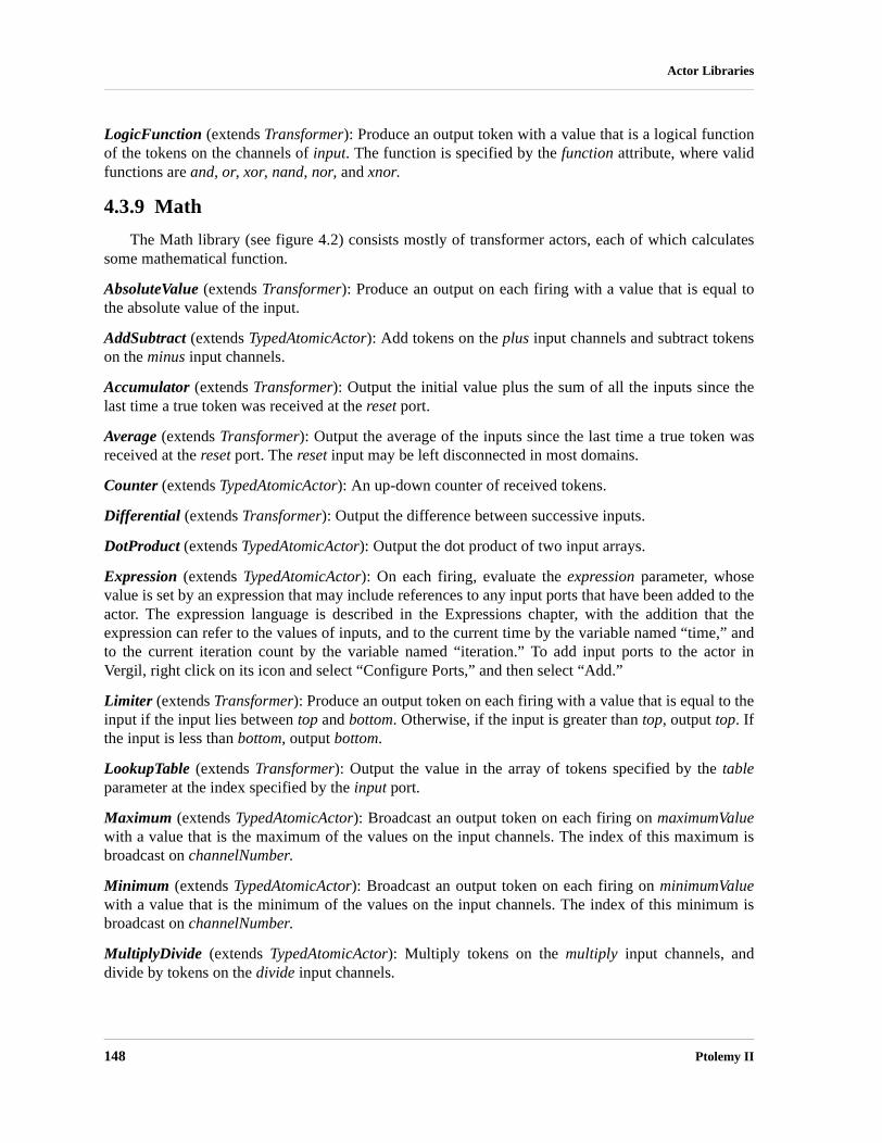
148 Ptolemy II
Actor Libraries
LogicFunction (extends Transformer): Produce an output token with a value that is a logical functionof the tokens on the channels of input. The function is specified by the function attribute, where validfunctions are and, or, xor, nand, nor, and xnor.
4.3.9 Math
The Math library (see figure 4.2) consists mostly of transformer actors, each of which calculatessome mathematical function.
AbsoluteValue (extends Transformer): Produce an output on each firing with a value that is equal tothe absolute value of the input.
AddSubtract (extends TypedAtomicActor): Add tokens on the plus input channels and subtract tokenson the minus input channels.
Accumulator (extends Transformer): Output the initial value plus the sum of all the inputs since thelast time a true token was received at the reset port.
Average (extends Transformer): Output the average of the inputs since the last time a true token wasreceived at the reset port. The reset input may be left disconnected in most domains.
Counter (extends TypedAtomicActor): An up-down counter of received tokens.
Differential (extends Transformer): Output the difference between successive inputs.
DotProduct (extends TypedAtomicActor): Output the dot product of two input arrays.
Expression (extends TypedAtomicActor): On each firing, evaluate the expression parameter, whosevalue is set by an expression that may include references to any input ports that have been added to theactor. The expression language is described in the Expressions chapter, with the addition that theexpression can refer to the values of inputs, and to the current time by the variable named “time,” andto the current iteration count by the variable named “iteration.” To add input ports to the actor inVergil, right click on its icon and select “Configure Ports,” and then select “Add.”
Limiter (extends Transformer): Produce an output token on each firing with a value that is equal to theinput if the input lies between top and bottom. Otherwise, if the input is greater than top, output top. Ifthe input is less than bottom, output bottom.
LookupTable (extends Transformer): Output the value in the array of tokens specified by the tableparameter at the index specified by the input port.
Maximum (extends TypedAtomicActor): Broadcast an output token on each firing on maximumValuewith a value that is the maximum of the values on the input channels. The index of this maximum isbroadcast on channelNumber.
Minimum (extends TypedAtomicActor): Broadcast an output token on each firing on minimumValuewith a value that is the minimum of the values on the input channels. The index of this minimum isbroadcast on channelNumber.
MultiplyDivide (extends TypedAtomicActor): Multiply tokens on the multiply input channels, anddivide by tokens on the divide input channels.
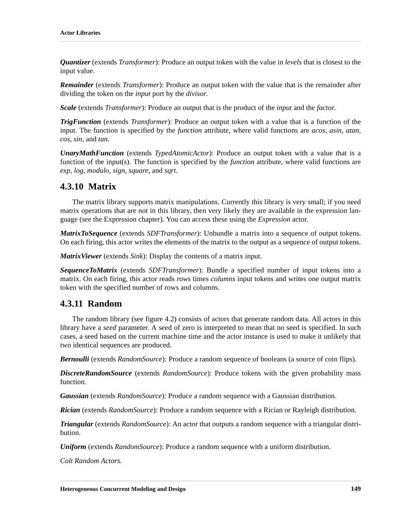
Heterogeneous Concurrent Modeling and Design 149
Actor Libraries
Quantizer (extends Transformer): Produce an output token with the value in levels that is closest to theinput value.
Remainder (extends Transformer): Produce an output token with the value that is the remainder afterdividing the token on the input port by the divisor.
Scale (extends Transformer): Produce an output that is the product of the input and the factor.
TrigFunction (extends Transformer): Produce an output token with a value that is a function of theinput. The function is specified by the function attribute, where valid functions are acos, asin, atan,cos, sin, and tan.
UnaryMathFunction (extends TypedAtomicActor): Produce an output token with a value that is afunction of the input(s). The function is specified by the function attribute, where valid functions areexp, log, modulo, sign, square, and sqrt.
4.3.10 Matrix
The matrix library supports matrix manipulations. Currently this library is very small; if you needmatrix operations that are not in this library, then very likely they are available in the expression lan-guage (see the Expression chapter). You can access these using the Expression actor.
MatrixToSequence (extends SDFTransformer): Unbundle a matrix into a sequence of output tokens.On each firing, this actor writes the elements of the matrix to the output as a sequence of output tokens.
MatrixViewer (extends Sink): Display the contents of a matrix input.
SequenceToMatrix (extends SDFTransformer): Bundle a specified number of input tokens into amatrix. On each firing, this actor reads rows times columns input tokens and writes one output matrixtoken with the specified number of rows and columns.
4.3.11 Random
The random library (see figure 4.2) consists of actors that generate random data. All actors in thislibrary have a seed parameter. A seed of zero is interpreted to mean that no seed is specified. In suchcases, a seed based on the current machine time and the actor instance is used to make it unlikely thattwo identical sequences are produced.
Bernoulli (extends RandomSource): Produce a random sequence of booleans (a source of coin flips).
DiscreteRandomSource (extends RandomSource): Produce tokens with the given probability massfunction.
Gaussian (extends RandomSource): Produce a random sequence with a Gaussian distribution.
Rician (extends RandomSource): Produce a random sequence with a Rician or Rayleigh distribution.
Triangular (extends RandomSource): An actor that outputs a random sequence with a triangular distri-bution.
Uniform (extends RandomSource): Produce a random sequence with a uniform distribution.
Colt Random Actors.

150 Ptolemy II
Actor Libraries
A new library of random number generators, developed jointly with David Bauer and KostasOikonomou from AT&T Research, is based on the popular Colt "Open Source Libraries for High Per-formance Scientific and Technical Computing in Java."1 The library supports many commonly usedprobability distributions and provides systematic management of seeds and random number generationtechniques.
4.3.12 Real Time
The behavior of the real time actors is affected by the amount of elapsed real time.
DelayStart (extends TypedAtomicActor): An actor that delays the execution of the model until a speci-fied time.
RealTimePlotter (extends Plotter): Plot input data as a function of elapsed real time.
Sleep (extends Transformer): Produce as output the tokens received on input after an amount of realtime specified by the sleepTime parameter.
VariableSleep (extends Transformer): Produce as output the tokens received on input after an amountof real time specified by the sleepTime input. NOTE: This will likely be replaced by a version of Sleepwith a PortParameter.
WallClockTime (extends Source): Output the elapsed real time in seconds.
4.3.13 Signal Processing
The signal processing library is divided into sublibraries.
Audio
The audio library provides actors that can read and write audio files, can capture data from anaudio input such as a CD or microphone, and can play audio data through the speakers of the comput-ers. It uses the javasound library, which is part of the Sun Microsystems’ Java 2 Standard Edition(J2SE) version 1.3.0 and higher. The AudioCapture and AudioPlayer actors are unusual in that theyhave coupled parameter values. Changing the parameters of one results in the parameters of the otherbeing changed. Also, as of this writing, they have the restriction that only one of each may be used in amodel at a time, and that if there are two models that use them, then those two models may not be exe-cuted simultaneously.
AudioCapture (extends Source): Capture audio from the audio input port of the computer, or from itsmicrophone, and produce the samples at the output.
AudioReader (extends Source): Read audio from a URL, and produce the samples at the output.
AudioPlayer (extends Sink): Play audio samples on the audio output port of the computer, or from itsspeakers.
AudioWriter (extends Sink): Write audio data to a file.
1. Colt is described at http://hoschek.home.cern.ch/hoschek/colt.

Heterogeneous Concurrent Modeling and Design 151
Actor Libraries
Communications
The communications library collects actors that support modeling and design of digital communi-cation systems. Many of these actors were written by Ye Zhou [156].
ConvolutionalCoder (extends Transformer): Encode an input sequence of bits using a convolutionalcode.
DeScrambler (extends Transformer): Descramble the input bit sequence using a feedback shift regis-ter.
HadamardCode (extends Source): Produce a Hadamard codeword by selecting a row from a Had-amard matrix.
HammingCoder (extends Transformer): Encode an input sequence of bits using Hamming code.
HammingDecoder (extends Transformer): Decode an input sequence of bits using Hamming code.
HuffmanCoder (extends Transformer): Given a probability distribution and alphabet, encode the inputusing Huffman code and send the result in booleans to the output port.
HuffmanDecoder (extends Transformer): Given a probability distribution and the correspondingalphabet, decode the input using Huffman code and send the result to the output port.
LempelZivCoder (extends Transformer): Lempel-Ziv encoder.
LempelZivDecoder (extends Transformer): Lempel-Ziv decoder.
LineCoder (extends SDFTransformer): Read a sequence of booleans (of length wordLength) andinterpret them as a binary index into the table, from which a token is extracted and sent to the output.
LMSAdaptive (extends FIR): Filter the input with an adaptive filter, and update the coefficients of thefilter using the input error signal according to the LMS (least mean-square) algorithm.
RaisedCosine (extends FIR): An FIR filter with a raised cosine frequency response. This is typicallyused in a communication systems as a pulse shaper or a matched filter.
Scrambler (extends Transformer): Scramble the input bit sequence using a feedback shift register.
Slicer (extends Transformer): A decoder of the LineCoder.
TrellisDecoder (extends ViterbiDecoder): Decode convolutional code with non-antipodal constella-tion.
ViterbiDecoder (extends Transformer): Decode inputs using (hard or soft) Viterbi decoding.
Filtering
DelayLine (extends SDFTransformer): In each firing, output the n most recent input tokens collectedinto an array, where n is the length of initialValues. In the beginning, before there are n most recenttokens, use the tokens from initialValues.
DownSample (extends SDFTransformer): Read factor inputs and produce only one of them on theoutput.

152 Ptolemy II
Actor Libraries
FIR (extends SDFTransformer): Produce an output token with a value that is the input filtered by anFIR filter with coefficients given by taps.
GradientAdaptiveLattice (extends Lattice): A lattice filter that adapts the reflection coefficients tominimize the power of the output sequence.
IIR (extends Transformer): Produce an output token with a value that is the input filtered by an IIR fil-ter using a direct form II implementation.
Lattice (extends Transformer): Produce an output token with a value that is the input filtered by an FIRlattice filter with coefficients given by reflectionCoefficients.
LinearDifferenceEquationSystem (extends Transformer): Linear system given by an [A, b, c, d] state-space model.
LMSAdaptive (extends FIR): Filter the input with an adaptive filter, and update the coefficients of thefilter using the input error signal according to the LMS (least mean-square) algorithm.
RecursiveLattice (extends Transformer): Produce an output token with a value that is the input filteredby a recursive lattice filter with coefficients given by reflectionCoefficients.
UpSample (extends SDFTransformer): Read one input token and produce factor outputs, with all butone of the outputs being a zero of the same type as the input.
VariableFIR (extends FIR): Filter the input sequence with an FIR filter with coefficients given on thenewTaps input port. The blockSize parameter specifies the number of successive inputs that are pro-cessed for each set of taps provided on newTaps.
VariableLattice (extends Lattice): Filter the input sequence with an FIR lattice filter with coefficientsgiven on the newCoefficients input port. The blockSize parameter specifies the number of successiveinputs that are processed for each set of taps provided on newCoefficients.
VariableRecursiveLattice (extends Lattice): Filter the input sequence with a recursive lattice filterwith coefficients given on the newCoefficients input port. The blockSize parameter specifies the num-ber of successive inputs that are processed for each set of taps provided on newCoefficients.
Spectrum
DB (extends Transformer): Produce a token that is the value in decibels (k*log10(z)) of the tokenreceived, where k is 10 if inputIsPower is true, and 20 otherwise. The output is never less than min (itis clipped if necessary).
FFT (extends SDFTransformer): A fast Fourier transform of size 2order.
IFFT (extends SDFTransformer): An inverse fast Fourier transform of size 2order.
LevinsonDurbin (extends SDFTransformer): Calculate the linear predictor coefficients (for both anFIR and Lattice filter) for the specified autocorrelation input.
MaximumEntropySpectrum (composite actor): A fancy spectrum estimator that uses the Levinson-Durbin algorithm to calculate linear predictor coefficients, and then uses those as a parametric modelfor the random process.

Heterogeneous Concurrent Modeling and Design 153
Actor Libraries
Periodogram (composite actor): A spectrum estimator calculates a periodogram.
PhaseUnwrap (extends Transformer): A simple phase unwrapper.
SmoothedSpectrum (composite actor): A spectrum estimator called the Blackman-Tukey algorithm,which estimates an autocorrelation function by averaging products of the input samples, and then cal-culates the FFT of that estimate.
Spectrum (composite actor): A simple spectrum estimator that calculates the FFT of the input. For arandom process, this is called the periodogram spectral estimate.
Statistical
A small number of statistical analysis actors are provided.
Autocorrelation (extends SDFTransformer): Estimate the autocorrelation by averaging products of theinput samples.
ComputeHistogram (extends TypedAtomicActor): Compute a histogram of input data.
PowerEstimate (extends Transformer): Estimate the power of the input signal.
4.3.14 String
The String library consists of actors that operate on strings.
StringCompare (extends TypedAtomicActor): Compute a specified string comparison function on thetwo string inputs. The function is specified by the function attribute, where valid functions are equals,startsWith, endsWith, and contains.
StringFunction (extends Transformer): Apply a specified function on the input string and send theresult to the output. The function is specified by the function attribute, where valid functions aretoLowerCase, toUpperCase, and trim.
StringIndexOf (extends TypedAtomicActor): Output the index of a string (searchFor) contained inanother string (inText).
StringLength (extends Transformer): Output the length of an input string.
StringMatches (extends TypedAtomicActor): Output true if matchString matches pattern, false other-wise.
StringReplace (extends TypedAtomicActor): Replace a substring of stringToEdit that matches patternby replacement. If replaceAll is true, then all matching substrings are replaced.
StringSubstring (extends Transformer): Output a substring of the input string, from the start index tostop.
4.3.15 Domain Specific
Several sublibraries contain actors that are primarily useful only with corresponding directors.

154 Ptolemy II
Actor Libraries
Continuous
The continuous-time library contains a set of actors designed specifically for use in the CTdomain.
DiscreteClock: Generate discrete events at prespecified time instants.
Continuous: Dynamics
The actors in this sublibrary have continuous-time dynamics (i.e., they involve integrators, andhence must coordinate with the differential equation solver).
Integrator: Integrate the input signal over time to produce the output signal. That is, the input is thederivative of the output with respect to time. This actor can be used to close feedback loops in CT todefine interesting differential equation systems.
Continuous Time: To Discrete
The actors in this sublibrary produce discrete event signals, which are signals that only have valuesat discrete points in time.
EventSource: Output a set of events at discrete set of time points.
Continuous Time
The continuous-time library contains a set of actors designed specifically for use in the CTdomain.
CTCase (extends Case): A version of the Case actor designed for the CT domain.
ContinuousClock: Generate a piecewise-constant signal with instantaneous transitions between levels.
TriggeredContinuousClock: Generate a piecewise-constant signal with instantaneous transitionsbetween levels, where two input ports are provided to start and stop the clock.
ContinuousSinewave: Generate a continuous-time sinusoidal signal.
CTCompositeActor: Composite actor to use when a continuous-time model is created within a contin-uous-time model.
Continuous Time: Dynamics
The actors in this sublibrary have continuous-time dynamics (i.e., they involve integrators, andhence must coordinate with the differential equation solver).
Integrator: Integrate the input signal over time to produce the output signal. That is, the input is thederivative of the output with respect to time. This actor can be used to close feedback loops in CT todefine interesting differential equation systems.

Heterogeneous Concurrent Modeling and Design 155
Actor Libraries
ContinuousTransferFunction: Filter the input with the specified rational Laplace transform transferfunction. Note that this actor constructs a submodel, so it might be interesting to right click on the actorand invoke “Open Actor” after it is initialized.
LinearStateSpace: Filter the input with a linear system. Note that this actor constructs a submodel, soit might be interesting to invoke “Open Actor” on the actor after it is initialized.
DifferentialSystem: Filter the input with the specified system, which can nonlinear, and is specifiedusing the expression language. Note that this actor constructs a submodel, so it might be interesting toinvoke “Open Actor” on the actor after it is initialized.
RateLimiter: Limit the first derivative of the input signal, so that the output changes no faster than thespecified limit.
Continuous Time: To Discrete
The actors in this sublibrary produce discrete event signals, which are signals that only have valuesat discrete points in time.
EventSource: Output a set of events at discrete set of time points.
LevelCrossingDetector: A event detector that converts continuous signals to discrete events when thecontinuous signal crosses a level threshold.
PeriodicSampler: Sample the input signal with the specified rate, producing discrete output events.
TriggeredSampler: Sample the input signal at times where the trigger input has a discrete input events.
ThresholdMonitor: Output true if the input value is in the interval [a, b], which is centered at thresh-oldCenter and has width thresholdWidth. This actor controls the integration step size so that the inputdoes not cross the threshold without producing at least one true output.
ZeroCrossingDetector: When the trigger is zero (within the specified errorTolerance), then output thevalue from the input port as a discrete event. This actor controls the integration step size to accuratelyresolve the time at which the zero crossing occurs.
Continuous Time: To Continuous
The actors in this sublibrary convert discrete event signals into continuous-time signals.
FirstOrderHold: Convert discrete events at the input to a continuous-time signal at the output by pro-jecting the value with the derivative.
ZeroOrderHold: Convert discrete events at the input to a continuous-time signal at the output by hold-ing the value of the discrete event until the next discrete event arrives.
4.3.16 Discrete Event
A library of actors is provided to particularly support discrete-event models. In discrete-eventmodels, signals consist of events placed in time, where time is a double. Events are processed in chro-nological order.
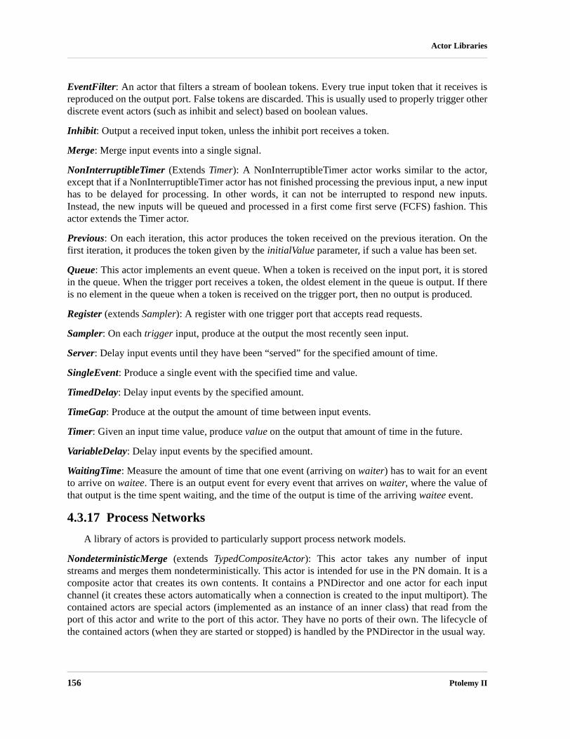
156 Ptolemy II
Actor Libraries
EventFilter: An actor that filters a stream of boolean tokens. Every true input token that it receives isreproduced on the output port. False tokens are discarded. This is usually used to properly trigger otherdiscrete event actors (such as inhibit and select) based on boolean values.
Inhibit: Output a received input token, unless the inhibit port receives a token.
Merge: Merge input events into a single signal.
NonInterruptibleTimer (Extends Timer): A NonInterruptibleTimer actor works similar to the actor,except that if a NonInterruptibleTimer actor has not finished processing the previous input, a new inputhas to be delayed for processing. In other words, it can not be interrupted to respond new inputs.Instead, the new inputs will be queued and processed in a first come first serve (FCFS) fashion. Thisactor extends the Timer actor.
Previous: On each iteration, this actor produces the token received on the previous iteration. On thefirst iteration, it produces the token given by the initialValue parameter, if such a value has been set.
Queue: This actor implements an event queue. When a token is received on the input port, it is storedin the queue. When the trigger port receives a token, the oldest element in the queue is output. If thereis no element in the queue when a token is received on the trigger port, then no output is produced.
Register (extends Sampler): A register with one trigger port that accepts read requests.
Sampler: On each trigger input, produce at the output the most recently seen input.
Server: Delay input events until they have been “served” for the specified amount of time.
SingleEvent: Produce a single event with the specified time and value.
TimedDelay: Delay input events by the specified amount.
TimeGap: Produce at the output the amount of time between input events.
Timer: Given an input time value, produce value on the output that amount of time in the future.
VariableDelay: Delay input events by the specified amount.
WaitingTime: Measure the amount of time that one event (arriving on waiter) has to wait for an eventto arrive on waitee. There is an output event for every event that arrives on waiter, where the value ofthat output is the time spent waiting, and the time of the output is time of the arriving waitee event.
4.3.17 Process Networks
A library of actors is provided to particularly support process network models.
NondeterministicMerge (extends TypedCompositeActor): This actor takes any number of inputstreams and merges them nondeterministically. This actor is intended for use in the PN domain. It is acomposite actor that creates its own contents. It contains a PNDirector and one actor for each inputchannel (it creates these actors automatically when a connection is created to the input multiport). Thecontained actors are special actors (implemented as an instance of an inner class) that read from theport of this actor and write to the port of this actor. They have no ports of their own. The lifecycle ofthe contained actors (when they are started or stopped) is handled by the PNDirector in the usual way.

Heterogeneous Concurrent Modeling and Design 157
Actor Libraries
Starver (extends Transformer): A base class for actors that transform an input stream into an outputstream.
4.3.18 Rendezvous
A library of actors is provided to particularly support rendezvous models.
Barrier (extends TypedAtomicActor): An actor for barrier synchronization.
Buffer (extends TypedAtomicActor): An actor representing a resource pool with a specified number ofresources.
Merge (extends TypedAtomicActor): An actor that merges input sequences onto one output sequence.
ResourcePool (extends TypedAtomicActor): An actor representing a resource pool with a specifiednumber of resources.
4.4 Data Polymorphism
A data polymorphic actor is one that can operate on any of a number of input data types. For exam-ple, AddSubtract can accept any numeric type of input.
Figure 4.4 shows the methods defined in the base class Token. Any data exchanged between actorsin Ptolemy II is wrapped in an instance of Token (or more precisely, in an instance of a class derivedfrom Token). Notice that add() and subtract() are methods of this base class. This makes it easy toimplement a data polymorphic adder.
It is instructive to examine the code in an actor that performs data polymorphic operations. Thefire() method of the AddSubtract actor is shown in figure 4.5. In this code, we first iterate through thechannels of plus input. The first token read (by the get() method) is assigned to sum. Subsequently, thepolymorphic add() method of that token is used to add additional tokens. The second iteration, over thechannels at the minus input port, is slightly trickier. If no tokens were read from the plus input, then thevariable sum is initialized by calling the polymorphic zero() method of the first token read at the minusport. The zero() method returns whatever a zero value is for the token in question.
Not all classes derived from Token override all its methods. For example, StringToken overridesadd() but not subtract(). Adding strings means simply concatenating them, but it is hard to assign a rea-sonable meaning to subtraction. Thus, if AddSubtract is used on strings, then the minus port must not
FIGURE 4.4. The Token class defines a polymorphic interface that includes basic arithmetic operations.
Token
+Token()+add(rightArg : Token) : Token+addReverse(leftArg : Token) : Token+convert(token : Token) : Token+divide(divisor : Token) : Token+divideReverse(dividend : Token) : Token+getType() : Type+isCloseTo(token : Token) : BooleanToken+isCloseTo(token : Token, epsilon : double) : BooleanToken+isEqualTo(token : Token) : BooleanToken+modulo(rightArg : Token) : Token+moduloReverse(leftArg : Token) : Token+multiply(rightFactor : Token) : Token+multiplyReverse(leftFactor : Token) : Token+one() : Token+subtract(rightArg : Token) : Token+subtractReverse(leftArg : Token) : Token+zero() : Token

158 Ptolemy II
Actor Libraries
ever receive tokens. It may be simply left disconnected, in which case minus.getWidth() returns zero.If the subtract() method of a StringToken is called, then a runtime exception will be thrown.
4.5 Domain Polymorphism
Most actors access their ports as shown in figure 4.5, using the hasToken(), get(), and send() meth-ods. Those methods are polymorphic, in that their exact behavior depends on the domain. For example,get() in the CSP domain causes a rendezvous to occur, which means that the calling thread is sus-pended until another thread sends data to the same port (using, for example, the send() method on oneof its ports). Correspondingly, a call to send() causes the calling thread to suspend until some otherthread calls a corresponding get(). In the PN domain, by contrast, send() returns immediately (if thereis room in the channel buffers), and only get() causes the calling thread to suspend.
Each domain has slightly different behavior associated with hasToken(), get(), send() and othermethods of ports. The actor, however, does not really care. The fire() method shown in figure 4.5 willwork for any reasonable implementation of these methods. Thus, the AddSubtract actor is domainpolymorphic.
Domains also have different behavior with respect to when the fire() method is invoked. In pro-cess-oriented domains, such as CSP and PN, a thread is created for each actor, and an infinite loop iscreated to repeatedly invoke the fire() method. Moreover, in these domains, hasToken() always returnstrue, since you can call get() on a port and it will not return until there is data available. In the DEdomain, the fire() method is invoked only when there are new inputs that happen to be the oldest onesin the model, and hasToken() returns true only if there is new data on the input port. The design ofactors for multiple domains is covered in the Designing Actors chapter.
FIGURE 4.5. The fire() method of the AddSubtract shows the use of polymorphic add() and subtract() meth-ods in the Token class (see figure 4.4).
public void fire() throws IllegalActionException {Token sum = null;for (int i = 0; i < plus.getWidth(); i++) {
if (plus.hasToken(i)) {if (sum == null) {
sum = plus.get(i);} else {
sum = sum.add(plus.get(i));}
}}for (int i = 0; i < minus.getWidth(); i++) {
if (minus.hasToken(i)) {Token in = minus.get(i);if (sum == null) {
sum = in.zero();}sum = sum.subtract(in);
}}if (sum != null) {
output.send(0, sum);}
}
Heterogeneous Concurrent Modeling and Design 159
5 Designing Actors
Authors: Christopher BrooksEdward A. LeeJie LiuXiaojun LiuSteve NeuendorfferYuhong XiongWinthrop Williams
5.1 Overview
Ptolemy is about component-based design. The domains define the semantics of the interactionbetween components. This chapter explains the common, domain-independent principles in the designof components that are actors. Actors are components with input and output that at least conceptuallyoperate concurrently with other actors.
The functionality of actors in Ptolemy II can be defined in a number of ways. The most basicmechanism is hierarchy, where an actor is defined as a composite of other actors. But composites arenot always the most convenient. Using Expression actor, for instance, is often more convenient forinvolved mathematical relations. The functionality is defined using the expression language explainedin an earlier chapter. Alternatively, you can use the MatlabExpression actor and give the behavior as aMATLAB script (assuming you have MATLAB installed). You can also define the behavior of an actorin Python, using the PythonActor or PythonScript actor. You can define the behavior in the experimen-tal Cal actor definition language [38]. But the most flexible method is to define the actor in Java. Thischapter explains how to do the latter. For the impatient, the appendix gives a tutorial walk through onthe construction and use in Vergil of a simple actor.
As explained in the previous chapter, some actors are designed to be domain polymorphic, mean-ing that they can operate in multiple domains. Others are domain specific. Refer to the domain chap-ters in volume 3 for domain-specific information relevant to the design of actors. This chapter explainshow to design actors so that they are maximally domain polymorphic. As also explained in the previ-

160 Ptolemy II
Designing Actors
ous chapter, many actors are also data polymorphic. This means that they can operate on a wide varietyof token types. Domain and data polymorphism help to maximize the reusability of actors and to mini-mize the amount of duplicated code when building an actor library.
Code duplication can also be avoided by using object-oriented inheritance. Inheritance can alsohelp to enforce consistency across a set of actors. Figure 4.1 shows a UML static structure diagram ofthe Ptolemy actor library. Three base classes, Source, Sink, and Transformer, exist to ensure consistentnaming of ports and to avoid duplicating code associated with those ports. Since most actors in thelibrary extend these base classes, users of the library can guess that an input port is named “input” andan output port is named “output,” and they will probably be right. Using base classes avoids input portsnamed “in” or “inputSignal” or something else. This sort of consistency helps to promote re-use ofactors because it makes them easier to use. Thus, we recommend using a reasonably deep class hierar-chy to promote consistency.
5.2 Anatomy of an Actor
Each actor consists of a source code file written in Java. Sources are compiled to Java byte code asdirected by the makefile in their directory. Thus, when creating a new actor, it is necessary to add itsname to the local makefile. Vergil, described fully in its own chapter, is the graphical design tool com-monly used to compose actors and other components into a complete program, a “Ptolemy model.” Tofacilitate using an actor in Vergil, it must appear in one of the actor libraries. This permits it to bedragged from the library pallet onto the design canvas. The libraries are XML files. Many of the actorlibraries are in the $PTII/ptolemy/actor/lib directory.
The basic structure of an actor is shown in figure 5.1. In that figure, keywords in bold are featuresof Ptolemy II that are briefly described here and described in more detail in the chapters of part 2. Italictext would be substituted with something pertinent in an actual actor definition.
We will go over this structure in detail in this chapter. The source code for existing Ptolemy IIactors, located mostly in $PTII/ptolemy/actor/lib, should also be viewed as a key reference.
5.2.1 Ports
By convention, ports are public members of actors. They represent a set of input and output chan-nels through which tokens may pass to other ports. Figure 5.1 shows a single port portName that is aninstance of TypedIOPort, declared in the line
public TypedIOPort portName;
Most ports in actors are instances of TypedIOPort, unless they require domain-specific services, inwhich case they may be instances of a domain-specific subclass, such as DEIOPort. The port is actu-ally created in the constructor by the line
portName = new TypedIOPort(this, "portName", true, false);
The first argument to the constructor is the container of the port, this actor. The second is the name ofthe port, which can be any string, but by convention, is the same as the name of the public member. Ifthe port name is not the same as the public member, then there will be problems with cloning, whichdepends on this naming convention. To present a different name to the user, call the setDisplayName()

Heterogeneous Concurrent Modeling and Design 161
Designing Actors
/** Javadoc comment for the actor class. */public class ActorClassName extends BaseClass implements MarkerInterface {
/** Javadoc comment for constructor. */public ActorClassName(CompositeEntity container, String name)
throws NameDuplicationException, IllegalActionException {super(container, name);// Create and configure ports, e.g. ...portName = new TypedIOPort(this, "portName", true, false);// Create and configure parameters, e.g. ...parameterName = new Parameter(this, "parameterName");parameterName.setExpression("0.0");parameterName.setTypeEquals(BaseType.DOUBLE);
}
/////////////////////////////////////////////////////////////////////// ports and parameters ////
/** Javadoc comment for port. */ public TypedIOPort portName;
/** Javadoc comment for parameter. */public Parameter parameterName;
/////////////////////////////////////////////////////////////////////// public methods ////
/** Javadoc comment for fire method. */public void fire() {
super.fire();... read inputs and produce outputs ...
}
/** Javadoc comment for initialize method. */public void initialize() {
super.initialize();... initialize local variables ...
}
/** Javadoc comment for prefire method. */public boolean prefire() {
... determine whether firing should proceed and return false if not ...return super.prefire();
}
/** Javadoc comment for preinitialize method. */public void preinitialize() {
super.preinitialize();... set port types and/or scheduling information ...
}
/** Javadoc comment for postfire method. */public boolean postfire() {
... update persistent state ...
... determine whether firing should continue to next iteration and return false if not ...return super.postfire();
}
/** Javadoc comment for wrapup method. */public void wrapup() {
super.wrapup();... display final results ...
}}
FIGURE 5.1. Anatomy of an actor.

162 Ptolemy II
Designing Actors
method. Note that calling setDisplayName() is optional. The third argument specifies whether the portis an input (it is in this example), and the fourth argument specifies whether it is an output (it is not inthis example). There is no difficulty with having a port that is both an input and an output, but it israrely useful to have one that is neither.
Multiports and Single Ports. A port can be a single port or a multiport. By default, it is a single port. Itcan be declared to be a multiport with a statement like
portName.setMultiport(true);
All ports have a width, which corresponds to the number of channels the port represents. If a port is notconnected, the width is zero. If a port is a single port, the width can be zero or one. If a port is a multi-port, the width can be larger than one.
Reading and Writing. Data (encapsulated in a token) can be sent to a particular channel of an outputport with the syntax
portName.send(channelNumber, token);
where channelNumber is the number of the channel (beginning with 0 for the first channel). The widthof the port, the number of channels, can be obtained by
int width = portName.getWidth();
If the port is unconnected, then the token is not sent anywhere. The send() method will simply return.Note that in general, if the channel number refers to a channel that does not exist, the send() methodsimply returns without complaining.
A token can be sent to all output channels of a port (or none if there are none) by
portName.broadcast(token);
You can generate a token from a value and then send this token by
portName.send(channelNumber, new IntToken(integerValue));
A token can be read from a channel by
Token token = portName.get(channelNumber);
You can read from channel 0 of a port and extract the contained value (if you know its type) by
double variableName = ((DoubleToken)portName.get(0)).doubleValue();
You can query an input port to see whether such a get() will succeed (whether a token is available) by
boolean tokenAvailable = portName.hasToken(channelNumber);

Heterogeneous Concurrent Modeling and Design 163
Designing Actors
You can also query an output port to see whether a send() will succeed using
boolean spaceAvailable = portName.hasRoom(channelNumber);
although with most current domains, the answer is always true. Note that the get(), hasRoom() and has-Token() methods throw IllegalActionException if the channel is out of range, but send() just silentlyreturns.
Type Constraints. Ptolemy II includes a sophisticated type system, described fully in the Type Systemchapter. This type system supports specification of type constraints in the form of inequalities betweentypes. These inequalities can be easily understood as representing the possibility of lossless conver-sion. Type a is less than type b if an instance of a can be losslessly converted to an instance of b. Forexample, IntToken is less than DoubleToken, which is less than ComplexToken. However, LongTokenis not less than DoubleToken, and DoubleToken is not less than LongToken, so these two types are saidto be incomparable.
Suppose that you wish to ensure that the type of an output is greater than or equal to the type of aparameter. You can do so by putting the following statement in the constructor:
portName.setTypeAtLeast(parameterName);
This is called a relative type constraint because it constrains the type of one object relative to the typeof another. Another form of relative type constraint forces two objects to have the same type, but with-out specifying what that type should be:
portName.setTypeSameAs(parameterName);
These constraints could be specified in the other order,
parameterName.setTypeSameAs(portName);
which obviously means the same thing, or
parameterName.setTypeAtLeast(portName);
which is not quite the same.Another common type constraint is an absolute type constraint, which fixes the type of the port
(i.e. making it monomorphic rather than polymorphic),
portName.setTypeEquals(BaseType.DOUBLE);
The above line declares that the port can only handle doubles. Another form of absolute type constraintimposes an upper bound on the type,
portName.setTypeAtMost(BaseType.COMPLEX);

164 Ptolemy II
Designing Actors
which declares that any type that can be losslessly converted to ComplexToken is acceptable. Bydefault, for any input port that has no declared type constraints, type constraints are automatically cre-ated that declares its type to be less than that of any output ports that have no declared type constraints.If there are input ports with no constraints, but no output ports lacking constraints, then those inputports will be unconstrained. Conversely, if there are output ports with no constraints, but no input portslacking constraints, then those output ports will be unconstrained. Of course, you can declare a port tobe unconstrained by saying
portName.setTypeAtMost(BaseType.GENERAL);
For full details of the type system, see the Type System chapter in volume 2.
Examples. To be concrete, consider first the code segment shown in figure 5.2, from the Transformerclass in the ptolemy.actor.lib package. This actor is a base class for actors with one input and one out-put. The code shows two ports, one that is an input and one that is an output. By convention, the Java-doc1 comments indicate type constraints on the ports, if any. If the ports are multiports, then theJavadoc comment will indicate that. Otherwise, they are assumed to be single ports. Derived classesmay change this, making the ports into multiports, in which case they should document this fact in the
1. Javadoc is a program that generates HTML documentation from Java files based on comments enclosed in “/** ... */”.
public class Transformer extends TypedAtomicActor {
/** Construct an actor with the given container and name. * @param container The container. * @param name The name of this actor. * @exception IllegalActionException If the actor cannot be contained * by the proposed container. * @exception NameDuplicationException If the container already has an * actor with this name. */ public Transformer(CompositeEntity container, String name) throws NameDuplicationException, IllegalActionException { super(container, name); input = new TypedIOPort(this, "input", true, false); output = new TypedIOPort(this, "output", false, true); }
/////////////////////////////////////////////////////////////////// //// ports and parameters ////
/** The input port. This base class imposes no type constraints except * that the type of the input cannot be greater than the type of the * output. */ public TypedIOPort input;
/** The output port. By default, the type of this output is constrained * to be at least that of the input. */ public TypedIOPort output;
}
FIGURE 5.2. Code segment showing the port definitions in the Transformer class.

Heterogeneous Concurrent Modeling and Design 165
Designing Actors
class comment. Derived classes may also set the type constraints on the ports.An extension of Transformer is shown in figure 5.3, the SimplerScale actor, which is a simplified
version of the Scale actor which is defined in $PTII/ptolemy/actor/lib/Scale.java. This actor producesan output token on each firing with a value that is equal to a scaled version of the input. The actor ispolymorphic in that it can support any token type that supports multiplication by the factor parameter.In the constructor, the output type is constrained to be at least as general as both the input and the fac-tor parameter.
Notice in figure 5.3 how the fire() method uses hasToken() to ensure that no output is produced ifthere is no input. Furthermore, only one token is consumed from each input channel, even if there ismore than one token available. This is generally the behavior of domain-polymorphic actors. Noticealso how it uses the multiply() method of the Token class. This method is polymorphic. Thus, this scaleactor can operate on any token type that supports multiplication, including all the numeric types andmatrices.
5.2.2 Port Rates and Dependencies Between Ports
Many Ptolemy II domains perform analysis of the topology of a model for the purposes of sched-uling. SDF, for example, constructs a static schedule that sequences the invocations of actors. DE, SR,and CT all examine data dependencies between actors to prioritize reactions to events that are simulta-neous. In all these cases, the director of the domain requires some additional information about thebehavior of actors in order to perform the analysis. In this section, we explain what additional informa-tion you can provide in an actor that will ensure that it can be used in all these domains.
Suppose you are designing an actor that does not require a token at its input port in order to pro-duce one on its output port. It is useful for the director to have access to this information. For example,the TimedDelay actor of the DE domain declares that its output port is independent of its input port bydefining this method:
public void pruneDependencies() { super.pruneDependencies(); removeDependency(input, output); }
An output port has a function dependency on an input port if in its fire() method, it sends tokens on theoutput port that depend on tokens gotten from the input port. By default, actors declare that each outputport depends on all input ports. If the actor writer does nothing, this is what a scheduler will assume.By overriding the pruneDependencies() method as above, the actor writer is asserting that for this par-ticular actor, the output port named output does not depend on the input named input in any given fir-ing. The scheduler can use this information to sequence the execution of the actors and to resolvecausality loops. For domains that do not use dependency information (such as Giotto and SDF), it isharmless to include the above the method. Thus, by making such declarations, you maximize the re-use potential of your actors.
Some domains (notably SDF) make use of information about production and consumption rates atthe ports of actors. If the actor writer does nothing, the SDF will assume that an actor requires and con-sumes exactly one token on each input port when it fires and produces exactly one token on each out-put port. To override this assumption, the actor writer only needs to include a parameter (an instance ofptolemy.data.expr.Parameter) in the port that is named either “tokenConsumptionRate” (for inputports) or “tokenProductionRate” (for output ports). The value of these parameters is an integer that

166 Ptolemy II
Designing Actors
import ptolemy.actor.lib.Transformer;import ptolemy.data.IntToken;import ptolemy.data.expr.Parameter;import ptolemy.data.Token;import ptolemy.kernel.util.*;import ptolemy.kernel.CompositeEntity;
public class SimplerScale extends Transformer {...public SimplerScale(CompositeEntity container, String name)
throws NameDuplicationException, IllegalActionException {super(container, name);factor = new Parameter(this, "factor");factor.setExpression("1");
// set the type constraints.output.setTypeAtLeast(input);output.setTypeAtLeast(factor);
}
/////////////////////////////////////////////////////////////////// //// ports and parameters ////
/** The factor. * This parameter can contain any token that supports multiplication. * The default value of this parameter is the IntToken 1. */ public Parameter factor;
/////////////////////////////////////////////////////////////////// //// public methods ////
/** Clone the actor into the specified workspace. This calls the * base class and then sets the type constraints. * @param workspace The workspace for the new object. * @return A new actor. * @exception CloneNotSupportedException If a derived class has * an attribute that cannot be cloned. */ public Object clone(Workspace workspace) throws CloneNotSupportedException { SimplerScale newObject = (SimplerScale)super.clone(workspace); newObject.output.setTypeAtLeast(newObject.input); newObject.output.setTypeAtLeast(newObject.factor); return newObject; }
/** Compute the product of the input and the <i>factor</i>. * If there is no input, then produce no output. * @exception IllegalActionException If there is no director. */ public void fire() throws IllegalActionException { if (input.hasToken(0)) { Token in = input.get(0); Token factorToken = factor.getToken(); Token result = factorToken.multiply(in); output.send(0, result); } }}
FIGURE 5.3. Code segment from the SimplerScale actor, showing the handling of ports and parameters.

Heterogeneous Concurrent Modeling and Design 167
Designing Actors
specifies the number of tokens consumed or produced in a firing. As always, the value of these param-eters can be given by an expression that depends on the parameters of the actor. Including these param-eters in the ports is harmless for domains that do not make use of this information, but including themmakes such actors useful in SDF, and hence improves their reusability.
In addition to production and consumption rates, feedback loops in SDF require that at least oneactor in the loop produce tokens in its initialize() method. To make the SDF scheduler aware that anactor does this, include a parameter in the output port that produces these tokens named “tokenInitPro-duction” with a value that is an integer specifying the number of tokens initially produced. The SDFscheduler will use this information to determine that a model with cycles does not deadlock.
5.2.3 Parameters
Like ports, parameters are public members of actors by convention. Figure 5.3 shows a parameterfactor that is an instance of Parameter, declared in the line
public Parameter factor;
and created in the line
factor = new Parameter(this, "factor");
Note that the second argument of the Parameter constructor ("factor"), must match name of the cor-responding Java field or else there will be problems with cloning the actor because the cloning mecha-nism depends on this naming convention. For example, the following is wrong:
factor = new Parameter(this, "my factor"); // Wrong! should be "factor"
To present a different name to the user, call the setDisplayName() method. Note that calling setDis-playName() is optional.
factor.setDisplayName("my factor"); // Right, but optional.
Continuing with figure 5.3, the default value of the parameter is set in the linefactor.setExpression("2*PI");
As with ports, you can specify type constraints on parameters. The most common type constraint isto fix the type, using
parameterName.setTypeEquals(BaseType.DOUBLE);
In fact, exactly the same relative or absolute type constraints that one can specify for ports can be spec-ified for parameters as well. But in addition, arbitrary constraints on parameter values are possible, notjust type constraints.
An actor is notified when a parameter value changes by having its attributeChanged() methodcalled. Consider the example shown in figure 5.4, taken from the PoissonClock actor. This actor gener-ates timed events according to a Poisson process. One of its parameters is meanTime, which specifiesthe mean time between events. This must be a double, as asserted in the constructor.
The attributeChanged() method is passed the parameter that changed. (Typically it is beingchanged by the user via the Configure dialog.) If this is meanTime, then this method checks to makesure that the specified value is positive, and if not, it throws an exception. This exception is presentedto the user in a new dialog box. It shows up when the user attempts to commit a non-positive value.

168 Ptolemy II
Designing Actors
The new dialog requests that the user choose a new value or cancel the change.A change in a parameter value sometimes has broader repercussions than just the local actor. It
may, for example, affect the schedule of execution of actors. An actor can call the invalidateSchedule()method of the director, which informs the director that any statically computed schedule (if there isone) is no longer valid. This would be used, for example, if the parameter affects the number of tokensproduced or consumed when an actor fires.
When the type of a parameter changes, the attributeTypeChanged() method in the actor containingthat parameter will be called. The default implementation of this method in TypedAtomicActor is toinvalidate type resolution. So parameter type change will cause type resolution to be performed in themodel. This default implementation is suitable for most actors. In fact, most of the actors in the actorlibrary do not override this method. However, if for some reason, an actor does not wish to redo typeresolution upon parameter type change, the attributeTypeChanged() method can be overridden. Butthis is rarely necessary.
5.2.4 Constructors
We have seen already that the major task of the constructor is to create and configure ports andparameters. In addition, you may have noticed that it calls
public class PoissonClock extends TimedSource {
public Parameter meanTime;public Parameter values;
public PoissonClock(CompositeEntity container, String name) throws NameDuplicationException, IllegalActionException {
super(container, name);meanTime = new Parameter(this, "meanTime");meanTime.setExpression("1.0");meanTime.setTypeEquals(BaseType.DOUBLE);...
}
/** If the argument is the meanTime parameter, check that it is * positive. * @exception IllegalActionException If the meanTime value is * not positive. */
public void attributeChanged(Attribute attribute) throws IllegalActionException { if (attribute == meanTime) { double mean = ((DoubleToken)meanTime.getToken()).doubleValue(); if (mean <= 0.0) { throw new IllegalActionException(this, "meanTime is required to be positive. meanTime given: " + mean); } } else if (attribute == values) { ArrayToken val = (ArrayToken)(values.getToken()); _length = val.length(); } else { super.attributeChanged(attribute); } }
...}
FIGURE 5.4. Code segment from the PoissonClock actor, showing the attributeChanged() method.

Heterogeneous Concurrent Modeling and Design 169
Designing Actors
super(container, name);
and that it declares that it throws NameDuplicationException and IllegalActionException. The latter isthe most widely used exception, and many methods in actors declare that they can throw it. The formeris thrown if the specified container already contains an actor with the specified name. For more detailsabout exceptions, see the Kernel chapter.
5.2.5 Cloning
All actors are cloneable. A clone of an actor needs to be a new instance of the same class, with thesame parameter values, but without any connections to other actors.
Consider the clone() method in figure 5.5, taken from the SimplerScale actor. This method beginswith:
SimplerScale newObject = (SimplerScale)super.clone(workspace);
The convention in Ptolemy II is that each clone method begins the same way, so that cloning works itsway up the inheritance tree until it ultimately uses the clone() method of the Java Object class. Thatmethod performs what is called a “shallow copy,” which is not sufficient for our purposes. In particu-lar, members of the class that are references to other objects, including public members such as ports
public class SimplerScale extends Transformer {...public SimplerScale(CompositeEntity container, String name)
throws NameDuplicationException, IllegalActionException {super(container, name);output.setTypeAtLeast(input);output.setTypeAtLeast(factor);
}
/////////////////////////////////////////////////////////////////// //// ports and parameters ////
/** The factor. The default value of this parameter is the integer 1. */ public Parameter factor;
/////////////////////////////////////////////////////////////////// //// public methods ////
/** Clone the actor into the specified workspace. This calls the * base class and then sets the type constraints. * @param workspace The workspace for the new object. * @return A new actor. * @exception CloneNotSupportedException If a derived class has * has an attribute that cannot be cloned. */ public Object clone(Workspace workspace) throws CloneNotSupportedException {
SimplerScale newObject = (SimplerScale)super.clone(workspace);newObject.output.setTypeAtLeast(newObject.input);newObject.output.setTypeAtLeast(newObject.factor);return newObject;
}...
}
FIGURE 5.5. Code segment from the SimplerScale actor, showing the clone() method.

170 Ptolemy II
Designing Actors
and parameters, are copied by copying the references. The NamedObj and TypedAtomicActor baseclasses implement a “deep copy” so that all the contained objects are cloned, and public members ref-
erence the proper cloned objects2.Although the base classes neatly handle most aspects of the clone operation, there are subtleties
involved with cloning type constraints. Absolute type constraints on ports and parameters are carriedautomatically into the clone, so clone() methods should never call setTypeEquals(). However, relativetype constraints are not cloned automatically because of the difficulty of ensuring that the other objectbeing referred to in a relative constraint is the intended one. Thus, in figure 5.5, the clone() methodrepeats the relative type constraints that were specified in the constructor:
newObject.output.setTypeAtLeast(newObject.input);newObject.output.setTypeAtLeast(newObject.factor);
Note that we set the type constraint to the cloned port not to the original port. Thus:
// WRONG: use the cloned ports, not the ports of the cloned object!newObject.output.setTypeAtLeast(input);newObject.output.setTypeAtLeast(factor);
is wrong, set the constraint to the cloned port.Note that at no time during cloning is any constructor invoked, so it is necessary to repeat in the
clone() method any initialization in the constructor. For example, the clone() method in the Expressionactor sets the values of a few private variables:
newObject._iterationCount = 1;newObject._time = (Variable)newObject.getAttribute("time");newObject._iteration =
(Variable)newObject.getAttribute("iteration");
5.3 Action Methods
Figure 5.1 shows a set of public methods called the action methods because they specify the actionperformed by the actor. By convention, these are given in alphabetical order in Ptolemy II Java files,but we will discuss them here in the order that they are invoked. The first to be invoked is the preini-tialize() method, which is invoked exactly once before any other action method is invoked. The preini-tialize() method is often used to set type constraints. After the preinitialize() method is called, typeresolution happens and all the type constraints are resolved. The initialize() method is invoked next,and is typically used to initialize state variables in the actor, which generally depends on type resolu-tion.
After the initialize() method, the actor experiences some number of iterations, where an iteration isdefined to be exactly one invocation of prefire(), some number of invocations of fire(), and at most one
2. Be aware that the implementation of the deep copy relies on a strict naming convention. Public members that reference ports and parameters must have the same name as the field that they are referencing in order to be properly cloned. For details, see section 5.2.1 and section 5.2.3.

Heterogeneous Concurrent Modeling and Design 171
Designing Actors
invocation of postfire().
5.3.1 Initialization
The initialize() method of the Average actor is shown in figure 5.6. This data- and domain-poly-morphic actor computes the average of tokens that have arrived. To do so, it keeps a running sum in aprivate variable _sum, and a running count of the number of tokens it has seen in a private variable_count. Both of these variables are initialized in the initialize() method. Notice that the actor alsocalls super.initialize(), allowing the base class to perform any initialization it expects to perform. Thisis essential because one of the base classes initializes the ports. An actor will almost certainly fail torun properly if super.initialize() is not called.
Note that the initialization of the Average actor does not affect, or depend on, type resolution. Thismeans that the code to initialize this actor can be placed either in the preinitialize() method, or in theinitialize() method. However, in some cases an actor may require part of its initialization to happenbefore type resolution, in the preinitialize() method, or part after type resolution, in the initialize()method. For example, an actor may need to dynamically create type constraints before each execu-tion3. Such an actor must create its type constraints in preinitialize(). On the other hand, an actor maywish to produce (send or broadcast) an initial output token once at the beginning of an execution of amodel. This production can only happen during initialize(), because data transport through portsdepends on type resolution.
5.3.2 Prefire
The prefire() method is the only method that is invoked exactly once per iteration4. It returns aboolean that indicates to the director whether the actor wishes for firing to proceed. The fire() methodof an actor should never be called until after its prefire() method has returned true. The most commonuse of this method is to test a condition to see whether the actor is ready to fire.
3. The need for this is relatively rare, but important. Examples include higher-order functions, which are actors that replace themselves with other subsystems, and certain actors whose ports are not created at the time they are constructed, but rather are added later. In most cases, the type constraints of an actor do not change and are sim-ply specified in the constructor.
4. Some domains invoke the fire() method only once per iteration, but others will invoke it multiple times (search-ing for global convergence to a solution, for example).
public class Average extends Transformer {...public void initialize() throws IllegalActionException {
super.initialize();_count = 0;_sum = null;
}...
/////////////////////////////////////////////////////////////////////// private members ////
private Token _sum;private int _count = 0;
}
FIGURE 5.6. Code segment from the Average actor, showing the initialize() method.

172 Ptolemy II
Designing Actors
Consider for example an actor that reads from trueInput if a private boolean variable _state istrue, and otherwise reads from falseInput. The prefire() method might look like this:
public boolean prefire() throws IllegalActionException {if (_state) {
return trueInput.hasToken(0);} else {
return falseInput.hasToken(0);}
}
It is good practice to check the superclass in case it has some reason to decline to be fired. The aboveexample becomes:
public boolean prefire() throws IllegalActionException {if (_state) {
return trueInput.hasToken(0) && super.prefire();} else {
return falseInput.hasToken(0) && super.prefire();}
}
The prefire() method can also be used to perform an operation that will happen exactly once periteration. Consider the prefire method of the Bernoulli actor in figure 5.7:
public class Bernoulli extends RandomSource {
public Bernoulli(CompositeEntity container, String name) throws NameDuplicationException, IllegalActionException {
super(container, name);
output.setTypeEquals(BaseType.BOOLEAN);
trueProbability = new Parameter(this, "trueProbability");trueProbability.setExpression("0.5");trueProbability.setTypeEquals(BaseType.DOUBLE);
}
public Parameter trueProbability;
public void fire() {super.fire();output.send(0, new BooleanToken(_current));
}
public boolean prefire() throws IllegalActionException {if (_random.nextDouble() < ((DoubleToken)(trueProbability.getToken())).doubleValue()) {
_current = true;} else {
_current = false;}return super.prefire();
}
private boolean _current;}
FIGURE 5.7. Code for the Bernoulli actor, which is not data polymorphic.

Heterogeneous Concurrent Modeling and Design 173
Designing Actors
public boolean prefire() throws IllegalActionException {if (_random.nextDouble() <
((DoubleToken)(trueProbability.getToken())).doubleValue()) {_current = true;
} else {_current = false;
}return super.prefire();
}
This method selects a new boolean value that will correspond to the token sent during each firing inthat iteration.
5.3.3 Fire
The fire() method is the main point of execution and is generally responsible for reading inputs andproducing outputs. It may also read the current parameter values, and the output may depend on them.Things to remember when writing fire() methods are:• To get data polymorphism, use the methods of the Token class for arithmetic whenever possible
(see the Data Package chapter). Consider for example the Average actor, shown in figure 5.8 onpage 174. Notice the use of the add() and divide() methods of the Token class to achieve data poly-morphism.
• When data polymorphism is not practical or not desired, then it is usually easiest to use the set-TypeEquals() to define the type of input ports. The type system will ensure that you can safely castthe tokens that you read to the type of the port. Consider again the Average actor shown in figure5.8. This actor declares the type of its reset input port to be BaseType.BOOLEAN. In the fire()method, the input token is read and cast to a BooleanToken. The type system ensures that no casterror will occur. The same can be done with a parameter, as with the Bernoulli actor shown in fig-ure 5.7.
• A domain-polymorphic actor cannot assume that there is data at all the input ports. Most domain-polymorphic actors will read at most one input token from each port, and if there are sufficientinputs, produce exactly one token on each output port.
• Some domains invoke the fire() method multiple times, working towards a converged solution.Thus, each invocation of fire() can be thought of as doing a tentative computation with tentativeinputs and producing tentative outputs. Thus, the fire() method should not update persistent state.Instead, that should be done in the postfire() method, as discussed in the next section.
• If an actor extends TypedAtomicActor (which in turn extends AtomicActor), then fire() should callsuper.fire() so that debugging messages can be printed if the NamedObj._debugging flag is true.However, if an actor extends TypedCompositeActor (which in turn extends CompositeActor), thenbe aware that it is not always correct to call super.fire() in the fire() method because CompositeAc-tor also transfers tokens. Thus, if an actor extends TypedCompositeActor transfers tokens, then theactor may just want to include the following in its fire():
if (_debugging) { _debug("Calling fire()"); }

174 Ptolemy II
Designing Actors
public class Average extends Transformer {
... constructor ...
/////////////////////////////////////////////////////////////////// //// ports and parameters ////
public TypedIOPort reset;
/////////////////////////////////////////////////////////////////// //// public methods ////
... clone method ...
public void fire() throws IllegalActionException { _latestSum = _sum; _latestCount = _count; // Check whether to reset. for (int i = 0; i < reset.getWidth(); i++) { if (reset.hasToken(i)) { BooleanToken r = (BooleanToken)reset.get(i); if (r.booleanValue()) { // Being reset at this firing. _latestSum = null; _latestCount = 1; } } } if (input.hasToken(0)) { Token in = input.get(0);
_latestCount++; if (_latestSum == null) { _latestSum = in; } else { _latestSum = _latestSum.add(in); } Token out = _latestSum.divide(new IntToken(_latestCount)); output.send(0, out); } }
public void initialize() throws IllegalActionException { super.initialize(); _count = 0; _sum = null; }
public boolean postfire() throws IllegalActionException {_sum = _latestSum;
_count = _latestCount; return super.postfire(); }
/////////////////////////////////////////////////////////////////// //// private members ////
private Token _sum; private Token _latestSum; private int _count = 0; private int _latestCount;}
FIGURE 5.8. Code segment from the Average actor, showing the action methods.

Heterogeneous Concurrent Modeling and Design 175
Designing Actors
and perhaps a comment about why super.fire() is not being called. For example, the higher order component (HOC) actor ptolemy.actor.lib.hoc.LifeCycleManager extends TypedCompositeActor, if an actor that extends LifeCycleManager has a fire method(), then the actor designer needs to consider whether fire() manages token transfer: if the fire() method in the actor does not transfer tokens, then calling super.fire() is probably correct, if it does transfer tokens, then consider not calling super.fire() and just check the _debugging flag and print if it is set.
5.3.4 Postfire
The postfire() method has two tasks:• updating persistent state, and• determining whether the execution of an actor is complete.Consider the fire() and postfire() methods of the Average actor in figure 5.8. Notice that the persistentstate variables _sum and _count are not updated in fire(). Instead, they are shadowed by_latestSum and _latestCount, and updated in postfire().
The return value of postfire() is a boolean that indicates to the director whether execution of theactor is complete. By convention, the director should avoid iterating further an actor after its postfire()method returns false. In other words, the director won’t call prefire(), fire(), or postfire() again duringthis execution of the model.
Consider the two examples shown in figure 5.9. These are base classes for source actors.SequenceSource is a base class for actors that output sequences. Its key feature is a parameter firing-CountLimit, which specifies a limit on the number of iterations of the actor. When this limit is reached,the postfire() method returns false. Thus, this parameter can be used to define sources of finitesequences.
TimedSource is similar, except that instead of specifying a limit on the number of iterations, itspecifies a limit on the current model time. When that limit is reached, the postfire() method returnsfalse.
5.3.5 Wrapup
The wrapup() method is used typically for displaying final results. It is invoked exactly once at theend of an execution, including when an exception occurs that stops execution (as opposed to an excep-tion occurring in, say, attributeChanged(), which does not stop execution). However, when an actor isremoved from a model during execution, the wrapup() method is not called.
An actor may lock a resource (which it intends to release in wrapup() for example), or its designermay have another reason to ensure that wrapup() always is called, even when the actor is removedfrom an executing model. This can be achieved by overriding the setContainer() method. In this case,the actor would have a setContainer() method which might look like this:
public void setContainer(CompositeEntity container) throws IllegalActionException, NameDuplicationException {
if (container != getContainer()) {wrapup();
}super.setContainer(container);

176 Ptolemy II
Designing Actors
public class SequenceSource extends Source implements SequenceActor {
public SequenceSource(CompositeEntity container, String name) throws NameDuplicationException, IllegalActionException { super(container, name); firingCountLimit = new Parameter(this, "firingCountLimit");
firingCountLimit.setExpression("0");firingCountLimit.setTypeEquals(BaseType.INT);
}
public Parameter firingCountLimit;
...public void attributeChanged(Attribute attribute)
throws IllegalActionException { if (attribute == firingCountLimit) { _firingCountLimit = ((IntToken)firingCountLimit.getToken()).intValue(); } }
...public boolean postfire() throws IllegalActionException {
if (_firingCountLimit != 0) {_iterationCount++;
if (_iterationCount == _firingCountLimit) {return false;
}}
return true;}
protected int _firingCountLimit;protected int _iterationCount = 0;
}
public class TimedSource extends Source implements TimedActor {
public TimedSource(CompositeEntity container, String name) throws NameDuplicationException, IllegalActionException { super(container, name); stopTime = new Parameter(this, "stopTime");
stopTime.setExpression("0.0");stopTime.setTypeEquals(BaseType.DOUBLE);...
}
public Parameter stopTime;
...
public boolean postfire() throws IllegalActionException {Time currentTime = getDirector().getModelTime();if (currentTime.compareTo(_stopTime) >= 0) {
return false;}return true;
}}
FIGURE 5.9. Code segments from the SequenceSource and TimedSource base classes.

Heterogeneous Concurrent Modeling and Design 177
Designing Actors
}
When overriding the setContainer() method in this way, it is best to make wrapup() idempotent(implying that it can be invoked many times without causing harm), because future implementations ofthe director might automatically unlock resources of removed actors, or call wrapup() on removedactors.
5.4 Coupled Port and Parameter
Often, in the design of an actor, it is hard to decide whether a quantity should be given by a port orby a parameter. Fortunately, you can design an actor to offer both options. An example of such an actoris shown in figure 5.10. This actor starts with an initial value, given by the init parameter, and incre-ments it each time by the value of step. The value of step is given by either a parameter named step ora port named step. To use the parameter exclusively, the model builder simply leaves the port uncon-nected. If the port is connected, then the parameter provides the default value, used before anythingarrives on the port. But after something arrives on the port, that is used.
When the model containing a Ramp actor is saved, only the parameter value is stored. No data thatarrives on the port is stored. Thus, the default value given by the parameter is persistent, while the val-ues that arrive on the port are transient.
To set up this arrangement, the Ramp actor creates an instance of the class PortParameter in itsconstructor, as shown in figure 5.10. This is a parameter that, when created, creates a coupled port.There is no need to explicitly create the port. The Ramp actor creates an instance of Parameter to spec-ify the init value, since it makes less sense for the value of init to be provided via a port.
Referring to figure 5.10, the constructor, after creating init and step, sets up type constraints. Thesespecify that the type of the output is at least as general as the types of init and step. The PortParameterclass takes care of an additional constraint, which is that the type of the step parameter must match thetype of the step port. The clone() method duplicates the type constraints that are given explicitly.
In the attributeChanged() method, the actor resets its state if init is the parameter that changed.This will work with an instance of Parameter, but it is not recommended for an instance of PortParam-eter. The reason is that each time you call getToken() on an instance of PortParameter, the methodchecks to see whether there is an input on the port, and consumes it if there is. Actors are expected toconsume inputs in their action methods, fire() and postfire(), not in attributeChanged(). Some domains,like SDF, will be confused by the consumption of the token too early.
In the Ramp actor in figure 5.10, the fire() method simply outputs the current state, whereas thepostfire() method calls getToken() on step and adds its value to the state. This follows the Ptolemy IIconvention that the state of the actor is not modified in fire(), but only in postfire(). Thus, this actor canbe used in domains with fixed-point semantics, such as SR.
When using a PortParameter in an actor, care must be exercised to call update() exactly once perfiring prior to calling getToken(). Each time update() is called, a new token will be consumed from theassociated port (if the port is connected and has a token). If this is called multiple times in an iteration,it may result in consuming tokens that were intended for subsequent iterations. Thus, for example,update() should not be called in fire() and then again in postfire(). Moreover, in some domains (suchas DE), it is essential that if a token is provided on a port, that it is consumed. In DE, the actor will berepeatedly fired until the token is consumed. Thus, it is an error to not call update() once per iteration.
It is important that the actor call getToken() exactly once in either the fire() method or in the post-

178 Ptolemy II
Designing Actors
fire() method. In particular, it should not call it in both, because this could result in consumption of twotokens from the input port, inappropriately. Moreover, it should always call it, even if it has no use forthe value. Otherwise, in the DE domain, the actor will be repeatedly fired if an input event is providedon the port but not consumed. Time cannot advance until that event is processed.
The way that the PortParameter class works is as follows. On each call to getToken(), the stepinstance of PortParameter first checks to see whether an input has arrived at the associated step port
public class Ramp extends SequenceSource {
public Ramp(CompositeEntity container, String name) throws NameDuplicationException, IllegalActionException { super(container, name); init = new Parameter(this, "init");
init.setExpression("0"); step = new PortParameter(this, "step");
step.setExpression("1");
// set the type constraints.output.setTypeAtLeast(init);output.setTypeAtLeast(step);
}
public Parameter init;public PortParameter step;
public void attributeChanged(Attribute attribute) throws IllegalActionException {if (attribute == init) {
_stateToken = init.getToken();} else {
super.attributeChanged(attribute);}
}
public Object clone(Workspace workspace) throws CloneNotSupportedException {Ramp newObject = (Ramp)super.clone(workspace);newObject.output.setTypeAtLeast(newObject.init);newObject.output.setTypeAtLeast(newObject.step);...return newObject;
}
public void fire() throws IllegalActionException {super.fire();output.send(0, _stateToken);
}
public void initialize() throws IllegalActionException {super.initialize();_stateToken = init.getToken();
}
...
public boolean postfire() throws IllegalActionException {step.update();_stateToken = _stateToken.add(step.getToken());return super.postfire();
}
private Token _stateToken = null;}
FIGURE 5.10. Code segments from the Ramp actor.

Heterogeneous Concurrent Modeling and Design 179
Designing Actors
since the last setExpression() or setToken(), and if so, returns a token read from that port. Also, anycall to get() on the associated port will result in the value of this parameter being updated, althoughnormally an actor writer will not call get() on the port.
5.5 Iterate Method
Some domains (such as SDF) will always invoke prefire(), fire(), and postfire() in sequence, oneafter another, so there is no benefit from having their functionality separated into three methods. More-over, in SDF this sequence of method invocations may be repeated a large number of times. An actordesigner can improve execution efficiency by providing an iterate() method. Figure 5.11 shows theiterate() method of the Ramp actor. Its behavior is equivalent to invoking prefire(), and that returnstrue, then invoking fire() and postfire() in sequence. Moreover the iterate() method takes an integerargument, which specifies how many times this sequence of operations should be repeated. The returnvalues are NOT_READY, STOP_ITERATING, or COMPLETED, which are constants defined in the Execut-able interface of the actor package. Returning NOT_READY is appropriate when prefire() would havereturned false. Returning STOP_ITERATING is appropriate when postfire() would have returned false.Otherwise, the proper return value is COMPLETED.
public class Ramp extends SequenceSource {
public Ramp(CompositeEntity container, String name) throws NameDuplicationException, IllegalActionException { super(container, name);
..._resultArray = new Token[1];
}
...public Object clone(Workspace workspace) throws CloneNotSupportedException {
..._resultArray = new Token[1];return newObject;
}
public int iterate(int count) throws IllegalActionException {// Check whether we need to reallocate the output token array.if (count > _resultArray.length) {
_resultArray = new Token[count];}for (int i = 0; i < count; i++) {
_resultArray[i] = _stateToken;step.update();_stateToken = _stateToken.add(step.getToken());
}output.send(0, _resultArray, count);if (_firingCountLimit != 0) {
_iterationCount += count; if (_iterationCount >= _firingCountLimit) {
return STOP_ITERATING; }
}return COMPLETED;
}
...
private Token[] _resultArray;}
FIGURE 5.11. More code segments from the Ramp actor of figure 5.10, showing the iterate() method.

180 Ptolemy II
Designing Actors
5.6 Time
An actor can access current model time using:
double currentTime = getDirector().getModelTime();
Notice that although the director has a public method setModelTime(), an actor should never use it.Typically, only another enclosing director will call this method.
An actor can request an invocation at a future time using the fireAt() or fireAtCurrentTime()method of the director. These methods return immediately (for a correctly implemented director). ThefireAt() method takes two arguments, an actor and a time. The fireAtCurrentTime() method takes onlyone argument, an actor. The director is responsible for performing one iteration of the specified actor atthe specified time. These methods can be used to get a source actor started, and to keep it operating. Inthe actor’s initialize() method, it can call fireAt() with a zero time. Then in each invocation of fire(), itcalls fireAt() again.
Note that while fireAt() can safely be called by any of the actors action methods, code which exe-cutes asynchronously from the director should avoid calling fireAt(). Examples of such code includethe private thread within the DatagramReader actor and the serialEvent() callback method of the Seri-alComm actor. Because these process hardware events, which can occur at any time, they instead usethe fireAtCurrentTime() method. The fireAt() is incorrect because model time may advance betweenthe call to getModelTime() and the call to fireAt(), which could result in fireAt() requesting a firing inthe past. This will trigger an exception.
5.7 Icons
An actor designer can specify a custom icon when defining the actor. A (very primitive) icon edi-tor is supplied with Ptolemy II version 4.0 and higher. To create an icon, in the File menu, select Newand then Icon Editor. An editor opens that contains a gray box for reference that is the size of thedefault icon that will be supplied if you do not create a custom icon. To create a custom icon, drag inthe visual elements from the library, set their parameters, and then save the icon in an XML file in thesame directory with the actor definition. If the name of the actor class is Foo, then the name of the fileshould be FooIcon.xml. That is, simply append “Icon” to the class name and complete the file namewith the extension “.xml”.
One useful feature that is not immediately evident in the user interface is that when you specify acolor to fill a geometric shape or to serve as the outline for the shape, you can make the color translus-cent. To do that, first choose the color using the color chooser that is made available by the parameterediting dialog for the geometric shape, then note that the color gets specified as a four-tuple of realnumbers that range from 0.0 to 1.0. The fourth of these numbers is the alpha channel for the color,which specifies transparency. A value of 1.0 makes the color opaque. A value of 0.0 makes the colorcompletely transparent (no color will be visible, and the background will show through). For conve-nience, you can specify the color to be “none” in which case a fully transparent color is supplied.
5.7.1 The Older Method
Many actors in the library use an older method to specify the icon. For completeness, we document

Heterogeneous Concurrent Modeling and Design 181
Designing Actors
that method here. The Ramp actor, for instance, specifies the icon shown in figure 5.12 using the codeshown in the constructor in figure 5.13. It uses a convenience method, _attachText(), which is aprotected method defined in the base class NamedObj. This method creates an attribute named“_iconDescription” with a textual value, where in this case, the textual value is:
<svg><rect x="-30" y="-20" width="60" height="40" style="fill:white"/><polygon points="-20,10 20,-10 20,10" style="fill:grey"/>
</svg>
This is XML, using the schema SVG (scalable vector graphics). The Ptolemy II visual editor (Vergil)is built on top of a graphics package called Diva, which has limited support for SVG. As of this writ-ing, the SVG elements that are supported are shown in figure 5.14. The positions in SVG are given byreal numbers, where the values are increasing to the right and down from the origin, which is the nom-inal center of the figure. The Ramp icon contains a white rectangle and a polygon that forms a triangle.
Most of the elements in figure 5.14 support style attributes, as summarized in the table. A styleattribute has value keyword:value. It can also have multiple keyword:value pairs, separated by semico-lons. For example, the keywords currently supported by the rect element are “fill”, “stroke” and“stroke-width.” The “fill” gives the color of the body of the figure (for figures for which this makessense), while the “stroke” gives the color of the outline. The supported colors are black, blue, cyan,darkgray, gray, green, lightgray, magenta, orange, pink, red, white, and yellow, plus any color sup-ported by the Java Color class getColor() method. The “stroke-width” is a real number giving thethickness of the outline line, where the default is 1.0.
The image element, although tempting, is problematic in the current implementation. Images arevery slow to load. It is not recommended.
FIGURE 5.12. The Ramp icon.
public class Ramp extends SequenceSource {
public Ramp(CompositeEntity container, String name) throws NameDuplicationException, IllegalActionException { super(container, name);
..._attachText("_iconDescription", "<svg>\n"
+ "<rect x=\"-30\" y=\"-20\" " + "width=\"60\" height=\"40\" " + "style=\"fill:white\"/>\n" + "<polygon points=\"-20,10 20,-10 20,10\" " + "style=\"fill:grey\"/>\n" + "</svg>\n");
}
...
}
FIGURE 5.13. The Ramp actor defines a custom icon as shown.

182 Ptolemy II
Designing Actors
Appendix B: Creating and Using a Simple Actor
This appendix walks through the construction of a simple actor and the inclusion of that actor inthe UserLibrary for use in Vergil. For this example, we are going to take the Ramp actor and changethe default step from 1 to 2. The new actor will be called Ramp2. Note that this example commits acardinal sin of software design: it copies code and makes small changes. It would be far better to sub-class the actor and make the necessary changes using object-oriented techniques such as overriding.However, to illustrate the process, this provides a quick way to get some working code.
The instructions below assume that you have installed the Java Development Kit (JDK), whichincludes the javac binary, that you have make and other tools installed, that Ptolemy II has beeninstalled, and that $PTII/configure and make have been run. In particular, the procedure will be differ-ent if you are using, for example, Eclipse as the software development environment. Under WindowsXP with JDK1.4 and Cygwin, to do the initial setup, after installing the source code, do this:
FIGURE 5.14. SVG subset currently supported by Diva, useful for creating custom icons.
SVG element Attributes
rect x: horizontal position of the upper left cornery: vertical position of the upper left cornerwidth: the width of the rectangleheight: the height of the rectanglestyle: fill, stroke, stroke-width
circle cx: horizontal position of the center of the circlecy: vertical position of the center of the circler: radius of the circlestyle: fill, stroke, stroke-width
ellipse cx: horizontal position of the center of the ellipsecy: vertical position of the center of the ellipserx: horizontal radius of the ellipsery: vertical radius of the ellipsestyle: fill, stroke, stroke-width
line x1: horizontal position of the start of the liney1: vertical position of the start of the linex2: horizontal position of the end of the liney2: vertical position of the end of the linestyle: stroke, stroke-width
polyline points: List of x,y pairs of points, vertices of line segments, delimited by commas or spacesstyle: stroke, stroke-width
polygon points: List of x,y pairs of points, vertices of the polygon, delimited by commas or spacesstyle: fill, stroke, stroke-width
text x: horizontal position of the texty: vertical position of the textstyle: font-family, font-size, fill
image x: horizontal position of the imagey: vertical position of the imagewidth: the width of the imageheight: the height of the imagexlink:href: A URL for the image

Heterogeneous Concurrent Modeling and Design 183
Designing Actors
bash-2.04$ PTII=c:/Ptolemy/ptII6.0.1bash-2.04$ export PTIIbash-2.04$ cd $PTIIbash-2.04$ ./configurebash-2.04$ make fast >& make.out
This will usually generate a few warnings, but once it completes, you have compiled the Ptolemy IItree. Below are the steps to add an actor:
1. Create a directory in which to put the new actor. It is most convenient if that directory is in the classpath, which is most easily accomplished by putting it somewhere inside the $PTII directory. For this example, we will assume you do
cd $PTIImkdir myActors
2. Create the new .java file that implements your actor:In this case, we are just copying a Ramp.java to Ramp.java
cd myActorscp $PTII/ptolemy/actor/lib/Ramp.java .
3. Edit Ramp.java and change:
package ptolemy.actor.lib;
to
package myActors;
You will need to add the imports:
import ptolemy.actor.lib.SequenceSource;
We also suggest that you change something about the actor, so that you can distinguish it from the original Ramp, such as changing:
step.setExpression("1");
to
step.setExpression("2");
4. Compile your actor:

184 Ptolemy II
Designing Actors
cd $PTII/myActorsjavac -classpath $PTII Ramp.java
5. Start Vergil.
vergil
If this does not work, you may not have created an alias for vergil. Try specifying the full pathname, like this.
"$PTII/bin/vergil"
6. In Vergil, click on File -> New -> Graph Editor
7. In the graph editor window, select from the Graph menu “Instantiate Entity”. In the dialog that pops up, enter the classname for your new actor, which is “myActors.Ramp”. An instance of the actor will be created in the graph editor.
8. You can now also put this actor into the UserLibrary so that it will be available any time you start Vergil. To do that, right click on the actor icon and select “Save Actor in Library”. This will open a new window, which is a representation of the UserLibrary with the new actor added to it. Save the UserLibrary, and your new actor will henceforth appear in the UserLibrary whenever you run Vergil. You can edit the UserLibrary like any other Ptolemy II model. A convenient way to open it is to right click on its icon in the library window on the left and select “Open for Editing”.
9. To test the new Ramp actor:
1. In a new graph editor window, drag the Ramp actor from UserLibrary to the main canvas on the right.
2. Click on Actors -> Sinks -> GenericSinks and drag a Display actor over to the main canvas.
3. Connect the two actors by clicking on the output of the Ramp actor and dragging over to the input of the Display actor.
4. Open the Directors library and drag the SDF Director over to the right window.
5. Select View -> Run and change the number of iterations from 0 to 10, then hit the Run button.
6. You should see the numbers from 0 to 18 in the display.

Heterogeneous Concurrent Modeling and Design 185
6 Coding Style
Authors: Christopher BrooksEdward A. Lee
6.1 Motivation
Collaborative software projects benefit when participants read code created by other participants.The objective of a coding style is to reduce the fatigue induced by unimportant formatting differencesand differences in naming conventions. Although individual programmers will undoubtedly have pref-erences and habits that differ from the recommendations here, the benefits that flow from followingthese recommendations far outweigh the inconveniences. Published papers in journals are subject tosimilar stylistic and layout constraints, so such constraints are not new to the academic community.
Software written by the Ptolemy Project participants follows this style guide. Although many ofthese conventions are arbitrary, the resulting consistency makes reading the code much easier, onceyou get used to the conventions. We recommend that if you extend Ptolemy II in any way, that you fol-low these conventions. To be included in future versions of Ptolemy II, the code must follow the con-ventions.
In general, we follow the Sun Java Style guide (http://java.sun.com/docs/codeconv/). We encour-age new developers to use Eclipse (http://www.eclipse.org) as their development platform. Eclipseincludes a Java Formatter, and we have found that the Java Conventions style is very close to ourrequirements.
A template that follows these rules can be found in $PTII/doc/coding/templates/Jav-aTemplate.java, where $PTII is the location of your Ptolemy II installation. In addition, severaluseful tools are provided in the directories under $PTII/util/ to help enforce the standards. • lisp/ptjavastyle.el is a lisp module for GNU Emacs that has appropriate indenting rules.
This file works well with Emacs under both Unix and Windows.• testsuite/jindent is a shell script that uses Emacs and the above module to properly indent
many files at once. This script works best under Unix, but can work under Windows with Cygwin.To see how this script would all the Java files in a directory, run:

186 Ptolemy II
Coding Style
$PTII/util/testsuite/jindent -q *.javaTo indent the files and check the changes in to CVS, remove the -q option.
• testsuite/ptspell is a shell script that checks Java code and prints out an alphabetical listof unrecognized spellings. It properly handles namesWithEmbeddedCapitalization and has a list ofauthor names. This script works best under Unix. Under Windows, it would require the installationof the ispell command as /usr/local/bin/ispell. To run this script, type$PTII/util/testsuite/ptspell *.java
• testsuite/chkjava is a shell script for checking various other potentially bad things in Javacode, such as debugging code, and FIXME’s. This script works under both Unix and Windows. Torun this script, type:$PTII/util/testsuite/chkjava *.java
6.2 Anatomy of a File
A Java file has the structure shown in figure 6.1. The key points to note about this organization are:• The file is divided into sections with highly visible delimiters. The sections contain constructors,
public variables (including ports and parameters for actor definitions), public methods, protectedvariables, protected members, private methods, and private variables, in that order. Note in partic-ular that although it is customary in the Java community to list private variables at the beginning ofa class definition, we put them at the end. They are not part of the public interface, and thus shouldnot be the first thing you see.
• Within each section, methods appear in alphabetical order, in order to easily search for a particularmethod (in printouts, for example, finding a method can be very difficult if the order is arbitrary,and use of printouts during design and code reviews is very convenient). If you wish to groupmethods together, try to name them so that they have a common prefix. Static methods are gener-ally mixed with non-static methods.
The key sections are explained below.
6.2.1 Copyright
The copyright used in Ptolemy II is shown in figure 6.2. This style of copyright is often referred tothe community as a “BSD” copyright because it was used for the “Berkeley standard distribution” ofUnix. It is much more liberal that the commonly used “GPL” or “Gnu Public License,” which encum-bers the software and derivative works with the requirement that they carry the source code and thesame copyright agreement. The BSD copyright requires that the software and derivative work carry theidentity of the copyright owner, as embodied in the lines:
Copyright (c) 1999-2007 The Regents of the University of California.All rights reserved.
The copyright also requires that copies and derivative works include the disclaimer of liability inBOLD. It specifically does not require that copies of the software or derivative works carry the middleparagraph, so such copies and derivative works need not grant similarly liberal rights to users of thesoftware.
The intent of the BSD copyright is to maximize the potential impact of the software by enablinguses of the software that are inconsistent with disclosing the source code or granting free redistribution

Heterogeneous Concurrent Modeling and Design 187
Coding Style
/* One line description of the class.
copyright notice
*/
package name;
imports, in alphabetical order;
////////////////////////////////////////////////////////////////////////////// ClassName/**Class documentation.
@author Author Name@version [email protected] color (email of proposer)@Pt.AcceptedRating color (email of accepter)*/public class ClassName ... {
constructors
/////////////////////////////////////////////////////////////////// //// public variables ////
public variables, in alphabetical order
/////////////////////////////////////////////////////////////////// //// public methods ////
public methods, in alphabetical order
/////////////////////////////////////////////////////////////////// //// protected methods ////
protected methods, in alphabetical order
/////////////////////////////////////////////////////////////////// //// protected variables ////
protected variables, in alphabetical order
/////////////////////////////////////////////////////////////////// //// private methods ////
private methods, in alphabetical order
/////////////////////////////////////////////////////////////////// //// private variables ////
private variables, in alphabetical order}
FIGURE 6.1. Anatomy of a Java file.

188 Ptolemy II
Coding Style
rights. For example, a commercial enterprise can extend the software, adding value, and sell the origi-nal software embodied with the extensions. Economic principles indicate that granting free redistribu-tion rights may render the enterprise business model untenable, so many business enterprises avoidsoftware with GPL licenses. Economic principles also indicate that, in theory, fair pricing of derivativeworks must be based on the value of the extensions, the packaging, or the associated services providedby the enterprise. The pricing cannot reflect the value of the free software, since an informed consumerwill, in theory, obtain that free software from another source.
Software with a BSD license can also be more easily included in defense or national-securityrelated applications, where free redistribution of source code and licenses may be inconsistent with themission of the software.
Ptolemy II can include other software with copyrights that are different from the BSD copyright.In general, we do not include software with the GNU General Public License (GPL) license, becauseprovisions of the GPL license require that software with which GLP’d code is integrated also beencumbered by the GPL license. We make an exception for GPL’d code that is aggregated withPtolemy II but not directly combined with Ptolemy II. For example cvs2cl.pl is a GPL’d Perl script thataccess the CVS database and generates a ChangeLog file. This script is not directly called by PtolemyII, and we include it as a “mere aggregation” and thus Ptolemy II does not fall under the GPL. Notethat we do not include GPL’d Java files that are compiled and then called from Ptolemy II because thiswould combine Ptolemy II with the GPL’d code and thus encumber Ptolemy II with the GPL.
Another GNU license is the GNU Library General Public License now known as the GNU LesserGeneral Public License (LGPL). We try to avoid packages that have this license, but we on occasionwe have included them with Ptolemy II. The LGPL license is less strict than the GPL - the LGPL per-mits linking with other packages without encumbering the other package.
Copyright (c) 1999-2007 The Regents of the University of California. All rights reserved. Permission is hereby granted, without written agreement and without license or royalty fees, to use, copy, modify, and distribute this software and its documentation for any purpose, provided that the above copyright notice and the following two paragraphs appear in all copies of this software.
IN NO EVENT SHALL THE UNIVERSITY OF CALIFORNIA BE LIABLE TO ANY PARTY FOR DIRECT, INDIRECT, SPECIAL, INCIDENTAL, OR CONSEQUENTIAL DAMAGES ARISING OUT OF THE USE OF THIS SOFTWARE AND ITS DOCUMENTATION, EVEN IF THE UNIVERSITY OF CALIFORNIA HAS BEEN ADVISED OF THE POSSIBILITY OF SUCH DAMAGE.
THE UNIVERSITY OF CALIFORNIA SPECIFICALLY DISCLAIMS ANY WARRANTIES, INCLUDING, BUT NOT LIMITED TO, THE IMPLIED WARRANTIES OF MERCHANTABILITY AND FITNESS FOR A PARTICULAR PURPOSE. THE SOFTWARE PROVIDED HEREUNDER IS ON AN "AS IS" BASIS, AND THE UNIVERSITY OF CALIFORNIA HAS NO OBLIGATION TO PROVIDE MAINTENANCE, SUPPORT, UPDATES, ENHANCEMENTS, OR MODIFICATIONS.
PT_COPYRIGHT_VERSION_2 COPYRIGHTENDKEY
FIGURE 6.2. Copyright notice used in Ptolemy II.

Heterogeneous Concurrent Modeling and Design 189
Coding Style
In general, it is best if you avoid GNU code. If you are considering using code with the GPL orLGPL, we encourage you to carefully read the license and to also consult the GNU GPL FAQ at http://www.gnu.org/licenses/gpl-faq.html.
We also avoid including software with proprietary copyrights that do not permit redistribution ofthe software.
The date of the copyright for newly created files should be the current year:Copyright (c) 2007 The Regents of the University of California.All rights reserved.
If a file is a copy of a previously copyrighted file, then the start date of the new file should be thesame as that of the original file:
Copyright (c) 1999-2007 The Regents of the University of California.All rights reserved.
Ideally, files should have at most one copyright from one institution. Files with multiple copyrightsare often in legal limbo if the copyrights conflict. If necessary, two institutions can share the samecopyright:
Copyright (c) 2007 The Ptolemy Institute and The Regents of theUniversity of California.All rights reserved.
Ptolemy II includes a copyright management system that will display the copyrights of packagesthat are included in Ptolemy II at runtime. Currently, URLs such as about: and about:copyrightare handled specially. If, within Ptolemy, the user clicks on a link with a target URL of about:copy-right, then we eventually invoke code within $PTII/ptolemy/actor/gui/GenerateCopyrights.java. Thisclass searches the runtime environment for particular packages and generates a web page with the linksto the appropriate copyrights if certain packages are found.
6.2.2 Imports
The imports section identifies the classes outside the current package on which this class depends.The package structure of Ptolemy II is carefully constructed so that core packages do not depend onmore elaborate packages. This limited dependencies makes it possible to create derivative works thatleverage the core but drastically modify or replace the more advanced capabilities.
By convention, we list imports by full class name, as follows:
import ptolemy.kernel.CompositeEntity;import ptolemy.kernel.Entity;import ptolemy.kernel.Port;import ptolemy.kernel.util.IllegalActionException;import ptolemy.kernel.util.Locatable;import ptolemy.kernel.util.NameDuplicationException;
in particular, we do not use the wildcards supported by Java, as in:

190 Ptolemy II
Coding Style
import ptolemy.kernel.*;import ptolemy.kernel.util.*;
The reason that we discourage wildcards is that the full class names in import statements makes it eas-ier find classes that are referenced in the code. If you use an IDE such as Eclipse, it is trivially easy togenerate the import list in this form, so there is no reason to not do it.
Imports are ordered alphabetically by package first, then by class name, as shown above.
6.3 Comment Structure
Good comments are essential to readable code. In Ptolemy II, comments fall into two categories,Javadoc comments, which become part of the generated documentation, and code comments, which donot. Javadoc comments are used to explain the interface to a class, and code comments are used toexplain how it works.
Both Javadoc and code comments should be complete sentences and complete thoughts, capital-ized at the beginning and with a period at the end. Spelling and grammar should be correct.
6.3.1 Javadoc and HTML
Javadoc is a program distributed with Java that generates HTML documentation files from Javasource code files1. Javadoc comments begin with “/**” and end with “*/”. The comment immedi-ately preceding a method, member, or class documents that method, member, or class. Ptolemy IIclasses include Javadoc documentation for all classes and all public and protected members and meth-ods. Members and methods should appear in alphabetical order within their protection category (pub-lic, protected etc.) so that it is easy to find them in the Javadoc output.
When writing Javadoc comments, pay special attention to the first sentence of each Javadoc com-ment. This first sentence is used as a summary in the Javadocs. It is extremely helpful if the first sen-tence is a cogent and complete summary.
Javadoc comments can include embedded HTML formatting. For example, by convention, in actordocumentation, we set in italics the names of the ports and parameters using the syntax
/** In this actor, inputs are read from the <i>input</i> port ... */
The Javadoc program gives extensive diagnostics when run on a source file. Our policy is to for-mat the comments until there are no Javadoc warnings. Private members and methods need not be doc-umented by Javadoc comments. The doccheck tool from http://java.sun.com/j2se/javadoc/doccheck/index.html gives even more extensive diagnostics in HTML format. We encourage developers to rundoccheck and fix all warnings.
6.3.2 Class documentation
The class documentation is the Javadoc comment that immediately precedes the class definitionline. It is a particularly important part of the documentation. It should describe what the class does andhow it is intended to be used. When writing it, put yourself in the mind of the user of your class. What
1. See http://java.sun.com/j2se/javadoc/writingdoccomments/ for guidelines from Sun Microsystems on writing Javadoc comments.

Heterogeneous Concurrent Modeling and Design 191
Coding Style
does that person need to know? In particular, that person probably does not need to know how youaccomplish what the class does. She only needs to know what you accomplish.
A class may be intended to be a base class that is extended by other programmers. In this case,there may be two distinct sections to the documentation. The first section should describe how a userof the class should use the class. The second section should describe how a programmer can meaning-fully extend the class. Only the second section should reference protected members or methods. Thefirst section has no use for them. Of course, if the class is abstract, it cannot be used directly and thefirst section can be omitted.
Comments should include honest information about the limitations of a class.Each class comment should also include the following javadoc tags:
• @authorThe @author tag should list the authors and contributors of a class, for example:@author Claudius Ptolemaus, Contributor: Tycho Brahe
• @versionThe @version tag includes text that CVS automatically substitutes in the version. The @versiontag starts out with:@version $Id$When the file is committed using CVS, the $Id$ gets substituted, so the tag might look like:@version $Id: NamedObj.java,v 1.213 2003/10/26 05:34:21 brahe Exp $Note that for CVS keyword substitution to work properly, the file must have the -kkv attribute set.Usually, this is the default, but for some odd reason, Eclipse might check in files with -kv. Thesolution is to runcvs admin -kkv filenamecvs update -A filename
• @sinceThe @since tag refers the release that the class first appeared in. Usually, this is one decimal placeafter the current release. For example if the current release is 3.0.2, then the @since tag wouldread:@since Ptolemy II 3.1Adding an @since tag to a new class is optional, we usually update these tags by running a scriptwhen we do a release. However, authors should be aware of their meaning. Note that the @sincetag can also be used when a method is added to an existing class, which will help users notice newfeatures in older code.
• @Pt.ProposedRating
• @Pt.AcceptedRatingCode rating tags, discussed below.
6.3.3 Code rating
The javadoc tags @Pt.ProposedRating and @Pt.AcceptedRating contain code rating infor-mation. Each tag includes the color (one of red, yellow, green, or blue) and the cvs login of theperson responsible for the proposed or accepted rating level, for example:
@Pt.ProposedRating blue [email protected] green ptolemy
The intent of the code rating is to clearly identify to readers of the file the level of maturity of the

192 Ptolemy II
Coding Style
contents. The Ptolemy Project encourages experimentation, and experimentation often involves creat-ing immature code, or even “throw-away” code. Such code is red. We use a lightweight software engi-neering process documented in “Software Practice in the Ptolemy Project,”2 to raise the code to higherratings. That paper documents the ratings a:
• Red code is untrusted code. This means that we have no confidence in the design or implementation (if there is one) of this code or design, and that anyone that uses it can expect it to change substantially and without notice. All code starts at red.• Yellow code is code with a trusted design. We have a reasonable degree of confidence in the design, and do not expect it to change in any substantial way. However, we do expect the API to shift around a little during development.• Green code is code with a trusted implementation. We have confidence that the implementation is sound, based on test suites and practical application of the code. If possible, we try not to release important code unless it is green.• Blue marks polished and complete code, and also represents a firm commitment to backwards-com-patibility. Blue code is completely reviewed, tested, documented, and stressed in actual usage.We use a javadoc doclet at $PTII/doc/doclets/RatingTaglet.java to add the ratings to the javadoc output.
6.3.4 Constructor documentation
Constructor documentation usually begins with the phrase “Construct an instance that ...” and goeson to give the properties of that instance. Note the use of the imperative case. A constructor is a com-mand to construct an instance of a class. What it does is construct an instance.
6.3.5 Method documentation
Method documentation needs to state what the method does and how it should be used. For exam-ple:
/** Mark the object invalid, indicating that when a method* is next called to get information from the object, that* information needs to be reconstructed from the database.*/
public void invalidate() {_valid = false;
}
By contrast, here is a poor method comment:
/** Set the variable _valid to false.*/
public void invalidate() {
2. J. Reekie, S. Neuendorffer, C. Hylands and E. A. Lee “Software Practice in the Ptolemy Project,” Technical Report Series, GSRC-TR-1999-01, Gigascale Semiconductor Research Center, University of California, Berke-ley, CA 94720, April 1999, http://ptolemy.eecs.berkeley.edu/ptolemyII/ptIIlatest/ptII/doc/coding/sftwareprac/index.htm

Heterogeneous Concurrent Modeling and Design 193
Coding Style
_valid = false;}
While this certainly describes what the method does from the perspective of the coder, it says nothinguseful from the perspective of the user of the class, who cannot see the (presumably private) variable_valid nor how that variable is used. On closer examination, this comment describes how the method isaccomplishing what it does, but it does not describe what it accomplishes.
Here is an even worse method comment:
/** Invalidate this object.*/
public void invalidate() {_valid = false;
}
This says absolutely nothing.Note the use of the imperative case in all of the above comments. It is common in the Java commu-
nity to use the following style for documenting methods:
/** Sets the expression of this variable. * @param expression The expression for this variable.*/
public void setExpression(String expression) {...
}
We use instead the imperative case, as in
/** Set the expression of this variable.* @param expression The expression for this variable.*/
public void setExpression(String expression) {...
}
The reason we do this is that our sentence is a well-formed, grammatical English sentence, while theusual convention is not (it is missing the subject). Moreover, calling a method is a command “do this,”so it seems reasonable that the documentation say “Do this.” The use of imperative case has a largeimpact on how interfaces are documented, especially when using the listener design pattern. Forinstance, the java.awt.event.ItemListener interface has the method:
/** Invoked when an item has been selected or deselected.* The code written for this method performs the operations* that need to occur when an item is selected (or deselected).*/
void itemStateChanged(ItemEvent e);
A naive attempt to rewrite this in imperative tense might result in:
194 Ptolemy II
Coding Style
/** Notify this object that an item has been selected or deselected.*/
void itemStateChanged(ItemEvent e);
However, this sentence does not capture what the method does. The method may be called in order tonotify the listener, but the method does not “notify this object”. The correct way to concisely documentthis method in imperative case (and with meaningful names) is:
/** React to the selection or deselection of an item.*/
void itemStateChanged(ItemEvent event);
The above is defining an interface (no implementation is given). To define the implementation, it isalso necessary to describe what the method does:
/** React to the selection or deselection of an item by doing...*/
void itemStateChanged(ItemEvent event) { ... implementation ... }
Comments for base class methods that are intended to be overridden should include informationabout what the method generally does, plus information that a programmer may need to override it. Ifthe derived class uses the base class method (by calling super.methodName()), but then appends toits behavior, then the documentation in the derived class should describe both what the base class doesand what the derived class does.
6.3.6 Referring to methods in comments
By convention, method names are set in the default font, but followed by empty parentheses, as in
/** The fire() method is called when ... */
The parentheses are empty even if the method takes arguments. The arguments are not shown. If themethod is overloaded (has several versions with different argument sets), then the text of the documen-tation needs to distinguish which version is being used.
Other methods in the same class may be linked to with the {@link ...} Javadoc tag. For example,to link to a foo() method that takes a String:
* Unlike the {@link #foo(String)} method, this method ...
Methods and members in the same package should have an octothorpe (# sign) prepended. Methodsand members in other classes should use the fully qualified class name:
{@link ptolemy.util.StringUtilities.substitute(String, String, String)}
Links to methods should include the types of the arguments.

Heterogeneous Concurrent Modeling and Design 195
Coding Style
To run Javadoc on the classes in the current directory, run make docs, which will create theHTML javadoc output in the doc/codeDoc subdirectory. To run Javadoc for all the common packages,run
cd $PTII/doc; make docs
The output will appear in $PTII/doc/codeDoc. Actor documentation can be viewed from withinVergil, right clicking on an actor and selecting View Documentation.
6.3.7 Tags in method documents
Methods should include Javadoc tags @param (one for each parameter), @return (unless thereturn type is void), and @exception (unless no exceptions are thrown). Note that we do not use the@throws tag, and that @returns is not a legitimate Javadoc tag, use @return instead.
The annotation for the arguments (the @param statement) need not be a complete sentence, sinceit is usually presented in tabular format. However, we do capitalize it and end it with a period.
Exceptions that are thrown by a method need to be identified in the Javadoc comment. An@exception tag should read like this:
* @exception MyException If such and such occurs.
Notice that the body always starts with "If", not "Thrown if", or anything else. Just look at the Javadocoutput to see why. In the case of an interface or base class that does not throw the exception, use thefollowing:
* @exception MyException Not thrown in this base class. Derived* classes may throw it if such and such happens.
The exception still has to be declared so that derived classes can throw it, so it needs to be documentedas well.
6.3.8 FIXME annotations
We use the keyword “FIXME” in comments to mark places in the code with known problems. Forexample:
// FIXME: The following cast may not always be safe.Foo foo = (Foo)bar;
To set up Eclipse to highlight FIXMEs, see the instructions in $PTII/doc/coding/eclipse.htm.
6.4 Code Structure
6.4.1 Names of classes and variables
In general, the names of classes, methods and members should consist of complete words sepa-rated using internal capitalization3. Class names, and only class names, have their first letter capital-ized, as in AtomicActor. Method and member names are not capitalized, except at internal word

196 Ptolemy II
Coding Style
boundaries, as in getContainer(). Protected or private members and methods are preceded by a leadingunderscore “_” as in _protectedMethod().
Static final constants should be in uppercase, with words separated by underscores, as inINFINITE_CAPACITY. A leading underscore should be used if the constant is protected or private.
Package names should be short and not capitalized, as in “de” for the discrete-event domain.In Java, there is no limit to name sizes (as it should be). Do not hesitate to use long names.
6.4.2 Indentation and brackets
Nested statements should be indented by 4 characters, as in:
if (container != null) {Manager manager = container.getManager();if (manager != null) {
manager.requestChange(change);}
}
Closing brackets should be on a line by themselves, aligned with the beginning of the line that containsthe open bracket. Please avoid using the Tab character in source files. The reason for this is that codebecomes unreadable when the Tab character is interpreted differently by different programs. Your texteditor should be configured to react to the Tab key by inserting spaces rather than the tab character. Toset up Emacs to follow the Ptolemy II indentation style, see $PTII/util/lisp/ptemacs.el. To set upEclipse to follow the Ptolemy II indentation style, see the instructions in $PTII/doc/coding/eclipse.htm.
Long lines should be broken up into many small lines. The easiest places to break long lines areusually just before operators, with the operator appearing on the next line. Long strings can be brokenup using the + operator in Java, with the + starting the next line. Continuation lines are indented by 8characters, as in the throws clause of the constructor in figure 6.1.
6.4.3 Spaces
Use a space after each comma:
Right: foo(a, b); Wrong: foo(a,b);
Use spaces around operators such as plus, minus, multiply, divide or equals signs, after semicolons andafter keywords like if, else, for, do, while, try, catch and throws:
Right: a = b + 1; Wrong: a=b+1; Right: for(i = 0; i < 10; i += 2) Wrong: for (i=0 ;i<10;i+=2)
Right: if ( a == b) {
3. Yes, there are exceptions (NamedObj, CrossRefList, IOPort). Many discussions dealt with these names, and we still regret not making them complete words.

Heterogeneous Concurrent Modeling and Design 197
Coding Style
Wrong: if(a==b)
6.4.4 Exceptions
A number of exceptions are provided in the ptolemy.kernel.util package. Use these exceptionswhen possible because they provide convenient constructor arguments of type Nameable that identifythe source of the exception by name in a consistent way.
A key decision you need to make is whether to use a compile-time exception or a run-time excep-tion. A run-time exception is one that implements the RuntimeException interface. Run-time excep-tions are more convenient in that they do not need to be explicitly declared by methods that throwthem. However, this can have the effect of masking problems in the code.
The convention we follow is that a run-time exception is acceptable only if the cause of the excep-tion can be tested for prior to calling the method. This is called a testable precondition. For example, ifa particular method will fail if the argument is negative, and this fact is documented, then the methodcan throw a run-time exception if the argument is negative. On the other hand, consider a method thattakes a string argument and evaluates it as an expression. The expression may be malformed, in whichcase an exception will be thrown. Can this be a run-time exception? No, because to determine whetherthe expression is malformed, you really need to invoke the evaluator. Making this a compile-timeexception forces the caller to explicitly deal with the exception, or to declare that it too throws thesame exception. In general, we prefer to use compile-time exceptions wherever possible.
When throwing an exception, the detail message should be a complete sentence that includes astring that fully describes what caused the exception. For example
throw IllegalActionException(this,"Cannot append an object of type: "
+ obj.getClass().getName() + " because "+ "it does not implement Cloneable.");
Note that the exception not only gives a way to identify the objects that caused the exception, but alsowhy the exception occurred. There is no need to include in the message an identification of the “this”object passed as the first argument to the exception constructor. That object will be identified when theexception is reported to the user.
If an exception is caught, be sure to use exception chaining to include the original exception. Forexample:
String fileName = foo();try {
// Try to open the file} catch (IOException ex) {
throw new IllegalActionException(this, ex,"Failed to open '" + fileName + "'");
}
6.4.5 Code Cleaning
Code cleaning is the act of homogenizing the coding style, looking for and repairing commonproblems. Fortunately, Eclipse includes a file formatter and a cleaner that fixes many common prob-
198 Ptolemy II
Coding Style
lems. Software that is to be formally released should be cleaned according to the guidelines set forth in$PTII/doc/coding/releasemgt.htm
6.5 Directory naming conventions
Individual demonstrations should be in directories under a demo/ directory. The name of thedirectory, and the name of the model should match and both begin with capital letters. The demosshould be capitalized so that it is possible to generate code for demonstrations. For example, the But-terfly demonstration is in sdf/demo/Butterfly/Butterfly.xml.
All other directories begin with lower case letters and most consist solely of lower case letters.

Heterogeneous Concurrent Modeling and Design 199
7 MoML
Authors: Edward A. LeeSteve Neuendorffer
Contributor: Christopher Hylands
7.1 Introduction
Ptolemy II models might be simulations (executable models of some other system) or implementa-tions (the system itself). They might be classical computer programs (applications), or any of a numberof network-integrated programs (applets, servlets, or CORBA services, for example).
Models can be specified in a number of ways. You can write Java code that instantiates compo-nents, parameterizes them, and interconnects them. Or you can use Vergil (see the Vergil chapterabove) to graphically construct models. Vergil stores models in ASCII files using an XML schemacalled MoML. MoML (which stands for Modeling Markup Language) is the primary persistent fileformat for Ptolemy II models. It is also the primary mechanism for constructing models whose defini-tion and execution is distributed over the network.
This chapter explains MoML. Most users will not need to edit MoML files directly. Use Vergilinstead. Occasionally, however, it is useful to examine and/or edit MoML files directly.
MoML is a modeling markup schema in the Extensible Markup Language (XML). It is intendedfor specifying interconnections of parameterized components. A MoML file can be executed as anapplication using any of the following commands,
ptolemy filename.xmlptexecute filename.xmlvergil filename.xmlmoml configuration.xml filename.xml
These commands are defined in the directory $PTII/bin, which must be in your path1, where $PTIIis the location of the Ptolemy II installation. In all cases, the filename can be replaced by a URL. The

200 Ptolemy II
MoML
ptolemy command assumes that the file defines an executable Ptolemy II model, and opens a controlpanel to execute it. The ptexecute command executes it without a control panel. The vergilcommand opens a graphical editor to edit and execute the model. The moml command uses the speci-fied configuration file (a MoML file containing a Ptolemy II configuration) to invoke some set of cus-tomized views or editors on the model. The filename extension can be “.xml” or “.moml” for MoMLfiles. And the same XML file can be used in an applet2.
To get a quick start, try entering the following into a file called test.xml (This file is also avail-able as $PTII/ptolemy/moml/demo/test.xml):
<?xml version="1.0" standalone="no"?><!DOCTYPE entity PUBLIC "-//UC Berkeley//DTD MoML 1//EN"
"http://ptolemy.eecs.berkeley.edu/xml/dtd/MoML_1.dtd"><entity name="test" class="ptolemy.actor.TypedCompositeActor">
<property name="director" class="ptolemy.domains.sdf.kernel.SDFDirector"/>
<entity name="ramp" class="ptolemy.actor.lib.Ramp"/><entity name="plot" class="ptolemy.actor.lib.gui.SequencePlotter"/><relation name="r" class="ptolemy.actor.TypedIORelation"/><link port="ramp.output" relation="r"/><link port="plot.input" relation="r"/>
</entity>
This code defines a model in a top-level entity called “test”. By convention, we use the same name forthe top-level model and the file in which it resides. The top-level model is an instance of the Ptolemy IIclass ptolemy.actor.TypedCompositeActor. It contains a director, two entities, a relation, andtwo links. The model is depicted in figure 7.1, where the director is not shown. It can be run using thecommand
ptolemy test.xml
You should get a window looking like that in figure 7.2. Enter “10” in the iterations box and hit the“Go” button to execute the model for 10 iterations (leaving the default “0” in the iterations box exe-
1. These commands are executed this way on Unix systems and on Windows systems with Cygwin installed. On other configurations, the equivalent commands are invoked in some other way.
2. An applet is a Java program that is downloaded from a web server by a browser and executed in the client’s computer (usually within a plug-in for the browser).
FIGURE 7.1. Simple example in the file $PTII/ptolemy/moml/demo/test.xml.
output
ramp plot
inputr
test

Heterogeneous Concurrent Modeling and Design 201
MoML
cutes it forever, until you hit the “Stop” button). The structure of the above MoML text is explained in detail in this chapter. A more interesting
example is given in the appendix to this chapter. You may wish to refer to that example as you readabout the details. The next chapter explains how to bypass MoML and write applets directly. The chap-ter after that describes the actors libraries that are included in the current Ptolemy II version.
7.2 MoML Principles
The key features of MoML include:• Web integration. MoML is an XML schema. XML, the popular extensible markup language[148],
provides a standard syntax and a standard way of defining the content within that syntax. The syn-tax is a subset of SGML[149], and is similar to HTML. It is intended for use on the Internet, and isintended for precisely this sort of specialization into schemas. File references are via URIs (inpractice, URLs), both relative and absolute, so MoML is equally comfortable working in appletsand applications.
• Implementation independence. MoML is designed to work with a variety of tools. A modeling toolthat reads MoML files is expected to provide a class loader in some form. Given the name of aclass, and possibly a URL for the class definition, the class loader must be able to instantiate it.Classes might be defined in MoML or in some base language such as Java. In Java, the class loadercould be that built in to the JVM. In C++ or other languages, the class loader would have to beimplemented by the modeling tool. Ptolemy II can be viewed as a reference implementation of aMoML tool that uses Java as its base language.
• Extensibility. Components can be parameterized in two ways. First, they can have named proper-ties with string values. Second, they can be associated with an external configuration file that canbe in any format understood by the component. Typically, the configuration will be in some otherXML schema, such as PlotML or SVG (scalable vector graphics).
• Classes and inheritance. Components can be defined in MoML as classes which can then be
FIGURE 7.2. Simple example of a Ptolemy II model execution control window.

202 Ptolemy II
MoML
instantiated in a model. Components can extend other components through an object-orientedinheritance mechanism.
• Semantics independence. MoML defines no semantics for an interconnection of components. Itrepresents only the hierarchical containment relationships between entities with properties, theirports, and the connections between their ports. In Ptolemy II, the meaning of a connection (thesemantics of the model) is defined by the director for the model, which is a property of the top-level entity. The director defines the semantics of the interconnection. MoML knows nothingabout directors except that they are instances of classes that can be loaded by the class loader andassigned as properties.
7.2.1 Clustered Graphs
A model is given as a clustered graph, which is an abstract syntax for representing netlists, statetransition diagrams, block diagrams, etc. An abstract syntax is a conceptual data organization. A par-ticular clustered graph configuration is called a topology. A topology is a collection of entities andrelations. Furthermore, entities have ports and relations connect the ports. We consistently use the termconnection to denote the association between connected ports (or their entities), and the term link todenote the association between ports and relations or between relations and relations. Thus, a connec-tion consists of one or more relations and two or more links.
The concept of an abstract syntax can be contrasted with a concrete syntax, which is a persistent,readable representation of the data. For example, EDIF is a concrete syntax for representing netlists.MoML is a concrete syntax for the clustered graph abstract syntax. Furthermore, we use the visualnotation shown in figure 7.3, where entities are depicted as rounded boxes, relations as diamonds, andentities as filled circles.
The use of ports and hierarchy distinguishes our topologies from mathematical graphs. In a mathe-matical graph, an entity would be a vertex, and an arc would be a connection between entities. A vertexcould be represented in our schema using entities that always contain exactly one port. In a directedgraph, the connections are divided into two subsets, one consisting of incoming arcs, and the other ofoutgoing arcs. The vertices in such a graph could be represented by entities that contain two ports, onefor incoming arcs and one for outgoing arcs. Thus, in mathematical graphs, entities always have one ortwo ports, depending on whether the graph is directed. Our schema generalizes this by permitting anentity to have any number of ports, thus dividing its connections into an arbitrary number of subsets.
FIGURE 7.3. Visual notation and terminology.
Port
Entity Entity
PortRelation
Link Link
Connection
Entity
Port
Connection Connection
Lin
k

Heterogeneous Concurrent Modeling and Design 203
MoML
A second difference between our graphs and mathematical graphs is that our relations are multi-way associations, whereas an arc in a graph is a two-way association. A third difference is that mathe-matical graphs normally have no notion of hierarchy (clustering).
Relations are intended to serve a mediators, in the sense of the Mediator design pattern [45].“Mediator promotes loose coupling by keeping objects from referring to each other explicitly...” Forexample, a relation could be used to direct messages passed between entities. Or it could denote a tran-sition between states in a finite state machine, where the states are represented as entities. Or it couldmediate rendezvous between processes represented as entities. Or it could mediate method callsbetween loosely associated objects, as for example in remote method invocation over a network.
7.2.2 Relation Groups
Relations mediate connections between ports. For flexibility, particularly with visual syntaxes, thePtolemy II abstract syntax permits any number of relations to be involved in any one connection. Fig-ure 7.5 illustrates this. Relations may be linked to other relations. Any two relations that are linked aresaid to be members of the same relation group. Specifically, a relation group is a maximal set of linkedrelations. Semantically, a relation group has the same meaning as a single relation. Thus, the two dia-grams in figure 7.5 have the same meaning.
7.2.3 Abstraction
Composite entities (clusters) are entities that can contain a topology (entities and relations). Clus-tering is illustrated by the example in figure 7.5. A port contained by a composite entity has inside aswell as outside links. Such a port serves to expose ports in the contained entities as ports of the com-posite. This is the converse of the “hiding” operator often found in process algebras. Ports within anentity are hidden by default, and must be explicitly exposed to be visible (linkable) from outside theentity3. The composite entity with ports thus provides an abstraction of the contents of the composite.
3. Unless level-crossing links are allowed. MoML supports these, but they are discouraged.
P1
P2
P3
P4 E4
P5
P6
FIGURE 7.4. Ports (P3 and P4) are linked to relations (R1 and R2) below their container (E1) in the hierar-chy. They may also be linked to relations at the same level (R3 and R4).
R1R2
R3
R4
E1
E3
E2
E5
E0

204 Ptolemy II
MoML
7.3 Specification of a Model
In this section, we describe the XML elements that are used to define MoML models.
7.3.1 Data Organization
As with all XML files, MoML files have two parts, one defining the MoML language and one con-taining the model data. The first part is called the document type definition, or DTD. This dual specifi-cation of content and structure is a key XML innovation. The DTD for MoML is given in figure 7.6. Ifyou are adept at reading these, it is a complete specification of the schema. However, since it is notparticularly easy to read, we explain its key features here.
Every MoML file must either contain or refer to a DTD. The simplest way to do this is with thefollowing file structure:
<?xml version="1.0" standalone="no"?><!DOCTYPE entity PUBLIC "-//UC Berkeley//DTD MoML 1//EN"
"http://ptolemy.eecs.berkeley.edu/xml/dtd/MoML_1.dtd"><entity name="modelname" class="classname">
model definition ...</entity>
Here, “model definition” is a set of XML elements that specify a clustered graph. The syntax forthese elements is described in subsequent sections. The first line above is required in any XML file. Itasserts the version of XML that this file is based on (1.0) and states that the file includes external refer-ences (in this case, to the DTD). The second and third lines declare the document type (model) andprovide references to the DTD.
The references to the DTD above refer to a “public” DTD. The name of the DTD is
-//UC Berkeley//DTD MoML 1//EN
which follows the standard naming convention of public DTDs. The leading dash “-” indicates thatthis is not a DTD approved by any standards body. The first field, surrounded by double slashes, is the
P1
P2
E3
P3
P4
FIGURE 7.5. A relation group is maximal set of linked relations. At the left, R1, R2, and R3 form a rela-tion group. A relation group is semantically identical to a single relation, so the two diagrams above have the same meaning.
R1R2
R3
E2
E1
E4
P1
P2
E3
P3
P4
R
E2
E1
E4
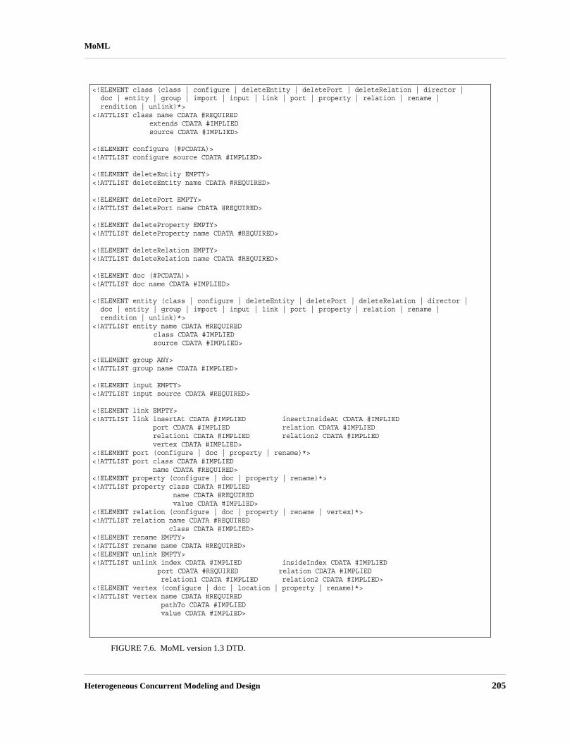
Heterogeneous Concurrent Modeling and Design 205
MoML
FIGURE 7.6. MoML version 1.3 DTD.
<!ELEMENT class (class | configure | deleteEntity | deletePort | deleteRelation | director |doc | entity | group | import | input | link | port | property | relation | rename |rendition | unlink)*>
<!ATTLIST class name CDATA #REQUIRED extends CDATA #IMPLIED source CDATA #IMPLIED>
<!ELEMENT configure (#PCDATA)><!ATTLIST configure source CDATA #IMPLIED>
<!ELEMENT deleteEntity EMPTY><!ATTLIST deleteEntity name CDATA #REQUIRED>
<!ELEMENT deletePort EMPTY><!ATTLIST deletePort name CDATA #REQUIRED>
<!ELEMENT deleteProperty EMPTY><!ATTLIST deleteProperty name CDATA #REQUIRED>
<!ELEMENT deleteRelation EMPTY><!ATTLIST deleteRelation name CDATA #REQUIRED>
<!ELEMENT doc (#PCDATA)><!ATTLIST doc name CDATA #IMPLIED>
<!ELEMENT entity (class | configure | deleteEntity | deletePort | deleteRelation | director |doc | entity | group | import | input | link | port | property | relation | rename |rendition | unlink)*>
<!ATTLIST entity name CDATA #REQUIREDclass CDATA #IMPLIEDsource CDATA #IMPLIED>
<!ELEMENT group ANY><!ATTLIST group name CDATA #IMPLIED>
<!ELEMENT input EMPTY><!ATTLIST input source CDATA #REQUIRED>
<!ELEMENT link EMPTY><!ATTLIST link insertAt CDATA #IMPLIED insertInsideAt CDATA #IMPLIED port CDATA #IMPLIED relation CDATA #IMPLIED
relation1 CDATA #IMPLIED relation2 CDATA #IMPLIED vertex CDATA #IMPLIED><!ELEMENT port (configure | doc | property | rename)*><!ATTLIST port class CDATA #IMPLIED name CDATA #REQUIRED><!ELEMENT property (configure | doc | property | rename)*><!ATTLIST property class CDATA #IMPLIED name CDATA #REQUIRED value CDATA #IMPLIED><!ELEMENT relation (configure | doc | property | rename | vertex)*><!ATTLIST relation name CDATA #REQUIRED class CDATA #IMPLIED><!ELEMENT rename EMPTY><!ATTLIST rename name CDATA #REQUIRED><!ELEMENT unlink EMPTY><!ATTLIST unlink index CDATA #IMPLIED insideIndex CDATA #IMPLIED
port CDATA #REQUIRED relation CDATA #IMPLIEDrelation1 CDATA #IMPLIED relation2 CDATA #IMPLIED>
<!ELEMENT vertex (configure | doc | location | property | rename)*><!ATTLIST vertex name CDATA #REQUIRED pathTo CDATA #IMPLIED value CDATA #IMPLIED>

206 Ptolemy II
MoML
name of the “owner” of the DTD, “UC Berkeley.” The next field is the name of the DTD, “DTDMoML 1” where the “1” indicates version 1 of the MoML DTD. The final field, “EN” indicates that thelanguage assumed by the DTD is English. The Ptolemy II MoML parser requires that the public DTDbe given exactly as shown, or it will not recognize the file as MoML.
In addition to the name of the DTD, the DOCTYPE element includes a URL pointing to a copy ofthe DTD on the web. If a particular MoML tool does not have access to a local copy of the DTD, thenit finds it at this web site.
The “entity” element may be replaced by a “class” element, as in:
<?xml version="1.0" standalone="no"?><!DOCTYPE class PUBLIC "-//UC Berkeley//DTD MoML 1//EN"
"http://ptolemy.eecs.berkeley.edu/xml/dtd/MoML_1.dtd"><class name="modelname" class="classname">
class definition ...</class>
We will say more about class definitions below.
7.3.2 Overview of XML
An XML document consists of the header tags “<?xml ... ?>” and “<!DOCTYPE ... >” fol-lowed by exactly one element. The element has the structure:
start tagbodyend tag
where the start tag has the form
<elementName attributes>
and the end tag has the form
</elementName>
The body, if present, can contain additional elements as well as arbitrary text. If the body is notpresent, then the element is said to be empty; it can optionally be written using the shorthand:
<elementName attributes/>
where the body and end tag are omitted.The attributes are given as follows:
<elementName attributeName="attributeValue" .../>
Which attributes are legal in an element is defined by the DTD. The quotation marks delimit the valueof the attributes, so if the attribute value needs to contain quotation marks, then they must be given

Heterogeneous Concurrent Modeling and Design 207
MoML
using the special XML entity “"” as in the following example:
<elementName attributeName=""foo""/>
The value of the attribute will be
"foo"
(with the quotation marks).In XML “"” is called an entity, creating possible confusion with our use of entity in
Ptolemy II. In XML, an entity is a named storage unit of data. Thus, “"” references an entitycalled “quot” that stores a double quote character.
7.3.3 Names and Classes
Most MoML elements have name and class attributes. The name is a handle for the object beingdefined or referenced by the element. In MoML, the same syntax is used to reference a pre-existingobject as to create a new object. If a new object is being created, then the class attribute (usually) mustbe given. If a pre-existing object is being referenced, or if the MoML reader has a built-in default classfor the element, then the class attribute is optional. If the class attribute is given, then the pre-existingobject must be an instance of the specified class.
A name is either absolute or relative. Absolute names begin with a period “.” and consist of aseries of name fields separated by periods, as in “.x.y.z”. Each name field can have alphanumeric char-acters, spaces, or the underscore “_” character. The first field is the name of the top-level model orclass object. The second field is the name of an object immediately contained by that top-level.
Any name that does not begin with a period is relative to the current context, the object defined orreferenced by an enclosing element. The first field of such a name refers to or defines an object imme-diately contained by that object. For example, inside of an object with absolute name “.x” the name“y.z” refers to an object with absolute name “.x.y.z”.
A name is required to be unique within its container. That is, in any given model, the absolutenames of all the objects must be unique. There can be two objects named “z”, but they must not beboth contained by “.x.y”.
Not much more will be said about classes. Particular implementations of MoML can use this fieldas necessary to specify different variations of the basic syntactic objects. The class names that are usedin the Ptolemy II implementation of MoML are always fully qualified Java class names. In addition, inPtolemy II a MoML file can be referenced as a class in the same way
7.3.4 Top-Level Entities
A very simple MoML file looks like this:
<?xml version="1.0" standalone="no"?><!DOCTYPE entity PUBLIC "-//UC Berkeley//DTD MoML 1//EN"
"http://ptolemy.eecs.berkeley.edu/xml/dtd/moml.dtd"><entity name="modelname" class="classname"></entity>

208 Ptolemy II
MoML
The entity element has name and class attributes, and defines a Ptolemy II model. This value of theclass attribute must be a class that instantiable by the MoML tool. For example, in Ptolemy II, we candefine a model with:
<?xml version="1.0" standalone="no"?><!DOCTYPE entity PUBLIC "-//UC Berkeley//DTD MoML 1//EN"
"http://ptolemy.eecs.berkeley.edu/xml/dtd/moml.dtd"><entity name="ptIImodel" class="ptolemy.actor.TypedCompositeActor"></entity>
Here, ptolemy.actor.TypedCompositeActor is a class that a Java class loader can find and thatthe MoML parser can instantiate. In Ptolemy II, it is a container class for clustered graphs representingexecutable models or libraries of instantiable model classes. A model can be an instance ofptolemy.kernel.util.NamedObj or any derived class, although most useful models will beinstances of ptolemy.kernel.CompositeEntity or a derived class. TypedCompositeAc-tor, as in the above example, is derived from CompositeEntity.
7.3.5 Entity Element
A model typically contains entities, as in the following Ptolemy II example:
<?xml version="1.0" standalone="no"?><!DOCTYPE entity PUBLIC "-//UC Berkeley//DTD MoML 1//EN"
"http://ptolemy.eecs.berkeley.edu/xml/dtd/moml.dtd"><entity name="ptIImodel" class="ptolemy.actor.TypedCompositeActor">
<entity name="source" class="ptolemy.actor.lib.Ramp"/><entity name="sink" class="ptolemy.actor.lib.SequencePlotter"/>
</entity>
Notice the common XML shorthand here of writing “<entity ... />” rather than “<entity...></entity>.” Of course, the shorthand only works if there is nothing in the body of the entityelement.
An entity can contain other entities, as shown in this example:
<entity name="ptIImodel" class="ptolemy.actor.TypedCompositeActor"><entity name="container" class="ptolemy.actor.TypedCompositeActor">
<entity name="source" class="ptolemy.actor.lib.Ramp"/></entity>
</entity>
An entity must specify a class unless the entity already exists in the containing entity or model. Thename of the entity reflects the container hierarchy. Thus, in the above example, the source entity hasthe full name “.ptIImodel.container.source”.
The definition of an entity can be distributed in the MoML file. Once created, it can be referred toagain by name as follows:
<entity name="top" class="classname"><entity name="x" class="classname"/>

Heterogeneous Concurrent Modeling and Design 209
MoML
...<entity name="x">
<property name="y"></entity>
</entity>
The property element (see section 7.3.6 below) is added to the pre-existing entity with name “x” whenthe second entity element is encountered.
In principle, MoML supports multiple containment, as in the following:
<entity name="top" class="classname"><entity name="x" class="classname"/>...<entity name="y" class="classname">
<entity name=".top.x"/></entity>
</entity>
Here, the element named “x” appears both in “top” and in “.top.y”, i.e. the same instance appears intwo different places. Thus, it would have two full names, “.top.x” and “.top.y.x”. However, Ptolemy IIdoes not support this, as it implements a strict container relationship, where an object can have onlyone container. Thus, attempting to parse the above MoML will result in an exception being thrown.
7.3.6 Properties
Entities (and some other elements) can be parameterized. There are two mechanisms. The simplestone is to use the property element:
<entity name="source" class="ptolemy.actor.lib.Ramp"><property name="init"
value="5"class="ptolemy.data.expr.Parameter"/>
</entity>
The property element has a name, at minimum (the value and class are optional). It is common for theenclosing class to already contain properties, in which case the property element is used only to set thevalue. For example:
<entity name="source" class="ptolemy.actor.lib.Ramp"><property name="init" value="5"/>
</entity>
In the above, the enclosing object (source, an instance of ptolemy.actor.lib.Ramp) must alreadycontain a property with the name init. This is typically how library components are parameterized. InPtolemy II, the value of a property may be an expression, as in “PI/50”. The expression may refer toother properties of the containing entity or of its container. Note that the expression language is notpart of MoML, but is rather part of Ptolemy II. In MoML, a property value is simply an uninterpretedstring. It is up to a MoML tool, such as Ptolemy II, to interpret that string.
A property can be declared without a class and without a pre-existing property if it is a pure prop-

210 Ptolemy II
MoML
erty, one with only a name and no value. For example:
<entity name="source" class="ptolemy.actor.lib.Ramp"><property name="abc"/>
</entity>
A property can also contain a property, as in
<property name="x" value="5"><property name="y" value="10"/>
</property>
A second, much more flexible mechanism is provided for parameterizing entities. The configureelement can be used to specify a relative or absolute URL pointing to a file that configures the entity,or it can be used to include the configuration information in line. That information need not be MoMLinformation. It need not even be XML, and can even be binary encoded data (although binary data can-not be in line; it must be in an external file). For example,
<entity name="sink" class="ptolemy.actor.lib.SequencePlotter"><configure source="url"/>
</entity>
Here, url can give the name of a file containing data, or a URL for a remote file. (For the Sequence-Plotter actor, that external data will have PlotML syntax; PlotML is another XML schema for config-uring plotters.) Configure information can also be given in the body of the MoML file as follows:
<entity name="sink" class="ptolemy.actor.lib.SequencePlotter"><configure>
configure information</configure>
</entity>
With the above syntax, the configure information must be textual data. It can contain XML markupwith only one restriction: if the tag “</configure>” appears in the textual data, then it must be pre-ceeded by a matching “<configure>”. That is, any configure elements in the markup must have bal-anced start and end tags.4
You can give both a source attribute and in-line configuration information, as in the following:
<entity name="sink" class="ptolemy.actor.lib.SequencePlotter"><configure source="url">
configure information</configure>
</entity>
4. XML allow markup to be included in arbitrary data as long as it appears within either a processing instruction or a CDATA body. However, for reasons that would only baffle anyone familiar with modern programming lan-guages, processing instructions and CDATA bodies cannot be nested within one another. The MoML configure element can be nested, so it offers a much more flexible mechanism than the standard ones in XML.

Heterogeneous Concurrent Modeling and Design 211
MoML
In this case, the file data will be passed to the application first, followed by the in-line configurationdata.
In Ptolemy II, the configure element is supported by any class that implements the Configurableinterface. That interface defines a configure() method that accepts an input stream. Both external filedata and in-line data are provided to the class as a character stream by calling this method.
There is a subtle limitation with using markup within the configure element. If any of the elementswithin the configure element match MoML elements, then the MoML DTD will be applied to assigndefault values, if any, to their attributes. Thus, this mechanism works best if the markup within theconfigure element is not using an XML schema that happens to have element names that match thosein MoML. Alternatively, if it does use MoML element names, then those elements are used with theirMoML meaning. This limitation can be fixed using XML namespaces, something we will eventuallyimplement.
7.3.7 Doc Element
Some elements can be documented using the doc element. For example,
<entity name="source" class="ptolemy.actor.lib.Ramp"><property name="init" value="5">
<doc>Initialize the ramp above the default because... </doc></property><doc>This actor produces an increasing sequence beginning with 5.</doc>
</entity>
With the above syntax, the documentation information must be textual data. It can include markup, asin the following example, which uses XHTML5 formatting within the doc element:
<entity name="source" class="ptolemy.actor.lib.Ramp"><doc><H1>Using HTML</H1>Text with <I>markup</I>.</doc>
</entity>
An alternative method is to use an XML processing instruction as follows:
<entity name="source" class="ptolemy.actor.lib.Ramp"><doc><?xhtml <H1>Using HTML</H1>Text with <I>markup</I>.?></doc>
</entity>
This requires that any utility that uses the documentation information be able to handle the xhtml pro-cessing instruction, but it makes it very clear that the contents are XHTML. However, for reasons wedo not understand, XML does not allow processing instructions to be nested, so this technique has itslimitations.
5. XHTML is HTML with additional constraints so that it conforms with XML syntax rules. In particular, every start tag must be matched by an end tag, something that ordinary HTML does not require (but fortunately, does allow).

212 Ptolemy II
MoML
More than one doc element can be included in an element. To do this, give each doc element aname, as follows:
<entity name="entityname" class="classname"><doc name="docname">
doc contents</doc>
</entity>
The name must not conflict with any preexisting property. If a doc element or a property with the spec-ified name exists, then it is removed and replaced with the property. If no name is given, then the docelement is assigned the name “_doc”.
A common convention, used in Ptolemy II, is to add doc elements with the name “tooltip” todefine a tooltip for GUI views of the component. A tooltip is a small window with short documenta-tion that pops up when the mouse lingers on the graphical component.
Note that the same limitation of using markup within configure elements also applies to doc ele-ments.
7.3.8 Ports
An entity can declare a port:
<entity name="A" class="classname"><port name="out"/>
</entity>
In the above example, no class is given for the port. If a port with the specified name already exists inthe class for entity A, then that port is the one referenced. Otherwise, a new port is created in PtolemyII by calling the newPort() method of the container. Alternatively, we can specify a class name, as in
<entity name="A" class="classname"><port name="out" class="classname"/>
</entity>
In this case, a port will be created if one does not already exist. If it does already exist, then its class ischecked for consistency with the declared class (the pre-existing port must be an instance of thedeclared class). In Ptolemy II, the typical classname for a port would be
ptolemy.actor.TypedIOPort
In Ptolemy II, the container of a port is required to be an instance of ptolemy.kernel.Entity or a derivedclass.
It is often useful to declare a port to be an input, an output, or both. To do this, enclose in the port aproperty named “input” or “output” or both, as in the following example:
<port name="out" class="ptolemy.actor.IOPort"><property name="output"/>

Heterogeneous Concurrent Modeling and Design 213
MoML
</port>
This is an example of a pure property. Optionally, the property can be given a boolean value, as in
<port name="out" class="ptolemy.actor.IOPort"><property name="output" value="true"/>
</port>
The value can be either “true” or “false”, where the latter will define the port to not be an output. Aport can be defined to be both an input and an output, as follows
<port name="out" class="ptolemy.actor.IOPort"><property name="output" value="true"/><property name="input" value="true"/>
</port>
It is also sometimes necessary to declare that a port is a multiport. To do this, enclose in the port aproperty named “multiport” as in the following example:
<port name="out" class="ptolemy.actor.IOPort"><property name="multiport"/>
</port>
The enclosing port must be an instance of IOPort (or a derived class such as TypedIOPort), or else theproperty is treated as an ordinary property. As with the input and output attribute, the multiport prop-erty can be given a boolean value, as in
<port name="out" class="ptolemy.actor.IOPort"><property name="multiport" value="true"/>
</port>
If a port is an instance of TypedIOPort (for library actors, most are), then you can set the type ofthe port in MoML as follows:
<port name="out" class="ptolemy.actor.IOPort"><property name="type"
value="double" class="ptolemy.actor.TypeAttribute"/>
</port>
This is occasionally useful when you need to constrain the types beyond what the built-in type systemtakes care of. The names of the built-in types are (currently) boolean, booleanMatrix, complex, com-plexMatrix, double, doubleMatrix, fix, fixMatrix, int, intMatrix, long, longMatrix, unsignedByte,unsignedByteMatrix, object, string, and general. These are defined in the classptolemy.data.type.BaseType.
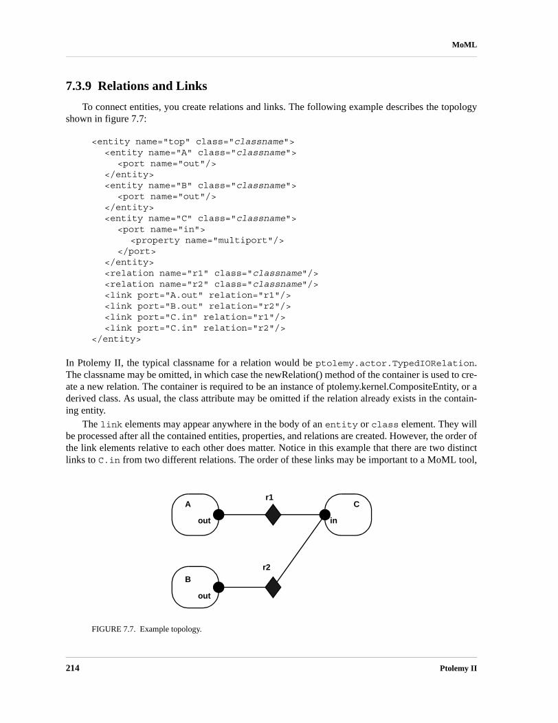
214 Ptolemy II
MoML
7.3.9 Relations and Links
To connect entities, you create relations and links. The following example describes the topologyshown in figure 7.7:
<entity name="top" class="classname"><entity name="A" class="classname">
<port name="out"/></entity><entity name="B" class="classname">
<port name="out"/></entity><entity name="C" class="classname">
<port name="in"><property name="multiport"/>
</port></entity><relation name="r1" class="classname"/><relation name="r2" class="classname"/><link port="A.out" relation="r1"/><link port="B.out" relation="r2"/><link port="C.in" relation="r1"/><link port="C.in" relation="r2"/>
</entity>
In Ptolemy II, the typical classname for a relation would be ptolemy.actor.TypedIORelation.The classname may be omitted, in which case the newRelation() method of the container is used to cre-ate a new relation. The container is required to be an instance of ptolemy.kernel.CompositeEntity, or aderived class. As usual, the class attribute may be omitted if the relation already exists in the contain-ing entity.
The link elements may appear anywhere in the body of an entity or class element. They willbe processed after all the contained entities, properties, and relations are created. However, the order ofthe link elements relative to each other does matter. Notice in this example that there are two distinctlinks to C.in from two different relations. The order of these links may be important to a MoML tool,
FIGURE 7.7. Example topology.
out
Ar1
r2
out
B
in
C

Heterogeneous Concurrent Modeling and Design 215
MoML
so any MoML tool must preserve the order in which they are specified, as Ptolemy II does. We say thatC has two links, indexed 0 and 1.
The link element can explicitly give the index number at which to insert the link. For example,we could have achieved the same effect above by saying
<link port="C.in" relation="r1" insertAt="0"/><link port="C.in" relation="r2" insertAt="1"/>
Whenever the insertAt option is not specified, the link is always appended to the end of the list oflinks.
When the insertAt option is specified, the link is inserted at that position, so any pre-existing linkswith larger indices will have their index numbers incremented. For example, if we do
<link port="C.in" relation="r1" insertAt="0"/><link port="C.in" relation="r2" insertAt="1"/><link port="C.in" relation="r3" insertAt="1"/>
then there will be a link to r1 with index 0, a link to r2 with index 2 (note! not 1), and a link to r3 withindex 1.
If the specified index is beyond the existing number of links, then null links (i.e. links to nothing)are created to fill in. So for example, if the first link we create is given by
<link port="C.in" relation="r2" insertAt="1"/>
then the port will have two links, not one, but the first one will be an empty link. If we then say
<link port="C.in" relation="r2"/>
then the port will have three links, with the first one being empty. If we then say
<link port="C.in" relation="r2" insertAt="0"/>
then there will be four links, with the second one being empty.Normally, it is not necessary in MoML to specify whether a link occurs on the inside of a port or
on the outside. This can be determined automatically by identifying the relation.For example, in figure5.4, port P4 is linked on the inside to relation R2 and on the outside to relations R3 and R4.
However, close examination of the DTD reveals that the relation attribute is optional. If the rela-tion attribute is not present, then a null link is inserted. However, if you do not specify a relation, thenthere is no way to determine whether an inside null link or an outside null link was intended. MoMLdefines the default to be an outside null link. To specify an inside null link, use the insertInsideAtattribute. For example, to insert a null link on the inside of P4 in figure 7.5 prior to the link to R2, use:
<entity name="E0.E1"> <link port="P4.in" insertInsideAt="0"/></entity>
Note that the index number is not the same thing as the channel number in Ptolemy II. In Ptolemy

216 Ptolemy II
MoML
II, a relation may have a width greater than one, so a single link may represent more than one channel(actually, it could even represent zero channels if that relation is not linked to another ports).
As mentioned above in section 7.2.2, relations can be linked to relations to form a relation group,as shown in figure 7.5. A link between relations is described as follows:
<link relation1="R1" relation2="R2"/>
Which relation is given as “relation1” vs. “relation2” is irrelevant. Also, there is no significance to theorder in which relations are linked, unlike the order in which ports are linked to relations. Thus, the“insertAt” or “insertInsideAt” attributes are not used with such a link, and will be ignored if they arespecified.
Also, unlike links between relations and ports, there is no significance to multiple links betweenthe same relations. Thus, in the following MoML, the second line is redundant and can be omitted withno change in meaning:
<link relation1="R1" relation2="R2"/><link relation1="R1" relation2="R2"/>
The same is not true of links between relations and ports.A relation group is a maximal set of linked relations. If a port links to multiple relations within the
same relation group, then the meaning is exactly the same as if the port were linked to just one relationin the group. The order in which a link between ports and relations in a group is made matters, but theorder in which links between relations are made does not. Thus, a relation group is semantically equiv-alent to a single relation where the links between ports and the single relation are made in the sameorder as the links between a port and relations in a relation group.
7.3.10 Classes
So far, entities have been instances of externally defined classes accessed via a class loader. Theycan also be instances of classes defined in MoML. To define a class in MoML, use the class element,as in the following example:6
<?xml version="1.0" standalone="no"?><!DOCTYPE class PUBLIC "-//UC Berkeley//DTD MoML 1//EN"
"http://ptolemy.eecs.berkeley.edu/xml/dtd/moml.dtd"><class name="Gen" extends="ptolemy.actor.TypedCompositeActor">
<entity name="ramp" class="ptolemy.actor.lib.Ramp"><port name="output"/><property name="step" value="2*PI/50"/>
</entity><entity name="sine" class="ptolemy.actor.lib.TrigFunction">
<port name="input"/><port name="output"/>
</entity><port name="output" class="ptolemy.actor.TypedIOPort"/><relation name="r1" class="ptolemy.actor.TypedIORelation"/>
6. This is a simplified version of the Sinewave class, whose complete definition is given in the appendix.

Heterogeneous Concurrent Modeling and Design 217
MoML
<relation name="r2" class="ptolemy.actor.TypedIORelation"/><link port="ramp.output" relation="r1"/><link port="sine.input" relation="r1"/><link port="sine.output" relation="r2"/><link port="output" relation="r2"/>
</class>
The class element may be the top-level element in a file, in which case the DOCTYPE should bedeclared as “class” as done above. It can also be nested within a model. The above example specifiesthe topology shown in figure 7.8. Once defined, it can be instantiated as if it were a class loaded by theclass loader:
<entity name="instancename" class="classname"/>
or<entity name="instancename" class="classname" source="url"/>
The first form can be used if the class definition can be found from the classname. There are two waysthat this could happen. First, the classname might match a class definition that is in scope; a class def-inition is in scope if the class is defined within the same container where the entity is being created, orwithin the container of that container, or the container of that container, etc. That is, once a class isdefined, it can be instantiated anywhere (deeply) within the container in which is defined. Second, theclassname might be sufficient to find the class definition in a file, much the way Java classes arefound. For example, if the classname is ptolemy.actor.lib.Sinewave and the class is defined inthe file $PTII/ptolemy/actor/lib/Sinewave.xml, then there is no need to use the second formto specify the URL where the class is defined. Specifically, the CLASSPATH7 is searched for a filematching the classname. By convention, the file defining the class has the same name as the class, withthe extension “.xml” or “.moml”.
7. CLASSPATH is an environment variable that Java uses to find Java classes. The Ptolemy II implementation of MoML simply leverages this so that MoML classes can also be found if they are on the CLASSPATH.
FIGURE 7.8. Sine wave generator topology.
output
Rampr1
input
Sineoutput
r2
output
Gen

218 Ptolemy II
MoML
An example of the first of these techniques is given below:
<?xml version="1.0" standalone="no"?><!DOCTYPE entity PUBLIC "-//UC Berkeley//DTD MoML 1//EN"
"http://ptolemy.eecs.berkeley.edu/xml/dtd/moml.dtd"><entity name="top" class="ptolemy.actor.TypedCompositeActor">
<class name="Gen" extends="ptolemy.actor.TypedCompositeActor">class definition ...
</class><entity name="inside" class="ptolemy.actor.TypedCompositeActor">
<entity name="instance" class="Gen"/></entity>
</entity>
The ability to give a URL as the source of a class definition is very powerful. It means that a modelmay be build from component libraries that are defined worldwide. There is no need to localize these.Of course, referencing a URL means the usual risks that the link will become invalid. It is our hopethat reliable and trusted sources of components will emerge who will not allow this to happen.
The Gen class given at the beginning of this subsection generates a sine wave with a period of 50samples. It is not all that useful without being parameterized. Let us extend it and add properties:8
<class name="Sinegen" extends="Gen"><property name="samplingFrequency"
value="8000.0"class="ptolemy.data.expr.Parameter">
<doc>The sampling frequency in Hertz.</doc></property><property name="frequency"
value="440.0"class="ptolemy.data.expr.Parameter">
<doc>The frequency in Hertz.</doc></property><property name="ramp.step"
value="frequency*2*PI/samplingFrequency"><doc>Formula for the step size.</doc>
</property><property name="ramp.init"
value="phase"></property>
</class>
This class extends Gen by adding two properties, and then sets the properties of the component entitiesto have values that are expressions.
8. This is still not quite as elaborate as the Sinewave class defined in the appendix, which is why we give it a slightly different name, Sinegen.

Heterogeneous Concurrent Modeling and Design 219
MoML
7.3.11 Inheritance
MoML supports inheritance by permitting you to extend existing classes. For example, considerthe following MoML file:
<?xml version="1.0" standalone="no"?><!DOCTYPE entity PUBLIC "-//UC Berkeley//DTD MoML 1//EN"
"http://ptolemy.eecs.berkeley.edu/xml/dtd/moml.dtd"><entity name="top" class="ptolemy.kernel.CompositeEntity">
<class name="base" extends="ptolemy.kernel.CompositeEntity"><entity name="e1" class="ptolemy.kernel.ComponentEntity"></entity>
</class><class name="derived" extends="base">
<entity name="e2" class="ptolemy.kernel.ComponentEntity"/></class><entity name="instance" classa=".top.derived"/>
</entity>
Here, the “derived” class extends the “base” class by adding another entity to it, and “instance” is aninstance of derived. The class “derived” can also give a source attribute, which gives a URL for thesource definition.
A derived class (or subclass) can contain additional entities, relations, ports, and links. However, itcannot remove entities, relations, ports or links defined in the base class. Moreover, it cannot add linksthat are exclusively between ports and relations defined in the base class. New links must involveeither a port or a relation that is new in the derived class.
7.3.12 Directors
Recall that a clustered graph in MoML has no semantics. However, a particular model has seman-tics. It may be a dataflow graph, a state machine, a process network, or something else. To give itsemantics, Ptolemy II requires the specification of a director associated with a model, an entity, or aclass. The director is a property of the model. The following example gives discrete-event semantics toa Ptolemy II model:
<entity name="top" class="ptolemy.actor.TypedCompositeActor"><property name="director"
class="ptolemy.domains.de.kernel.DEDirector"><property name="stopTime" value="100.0"/>
</property>...
</entity>
This example also sets a property of the director. The name of the director is not important, except thatit cannot collide with the name of any other property in the model.

220 Ptolemy II
MoML
7.3.13 Input Element
It is possible to insert MoML from another file or URL into a particular point in your model. Forexample:
<entity name="top" class="..."><entity name="a" class="...">
<input source="url"/></entity>
</entity>
This takes the contents of the URL specified in the source attribute of the input element and placesthem inside the entity named “a”. The base of the current document (the one containing the importstatement) is used to interpret a relative URL, or if the current document has no base, then the currentworking directory is used, or if that fails, the current CLASSPATH.
7.3.14 Annotations for Visual Rendering
The abstract syntax of MoML, clustered graphs, is amenable to visual renditions as bubble and arcdiagrams or as block diagrams. To support tools that display and/or edit MoML files visually, MoMLallows a relation to optionally have a vertex which gives it a specific physical location in a visual syn-tax. For example:
<relation name="r" class="ptolemy.actor.TypedIORelation"><vertex name="v1" class="classname" value="location"/>
</relation>
A visual rendition (such as that created by Vergil, the visual interface for Ptolemy II) would render therelation with a located icon, rather than simply as a wire between ports. Figure 7.9 illustrates two links,the top one of which has a vertex, and the bottom one of which does not. The two are semanticallyidentical, but obviously the rendition is different. In Ptolemy II, a vertex is given as follows:
<vertex name="v1" class="ptolemy.moml.Vertex" value="{184.0, 93.0}"/>
This indicates that the vertex should be rendered at the location 184.0, 93.0.
FIGURE 7.9. Example showing how a vertex contained by a relation results in a visual representation of the relation at a specific location (top) vs. a relation with no vertex that is rendered as a wire (bottom). The two connections have the same meaning.
A B
BA

Heterogeneous Concurrent Modeling and Design 221
MoML
Ptolemy II uses ordinary MoML properties to specify other visual aspects of a model. First, anentity can contain a location property, which is a hint to a visual renderer, as follows:
<entity name="ramp" class="ptolemy.actor.lib.Ramp"><property name="location"
class="ptolemy.moml.Location" value="50.0, 50.0"/>
</entity>
This suggests to the visual renderer that the Ramp actor should be drawn at location 50.0, 50.0.
7.4 Incremental Parsing
MoML may be used as a command language to modify existing models, as well as being used tospecify complete models. This technique is known as incremental parsing.
7.4.1 Adding Entities
Consider for example the simple model created as follows:
<?xml version="1.0" standalone="no"?><!DOCTYPE entity PUBLIC "-//UC Berkeley//DTD MoML 1//EN"
"http://ptolemy.eecs.berkeley.edu/xml/dtd/moml.dtd"><entity name="top" class="ptolemy.actor.TypedCompositeActor"> ... contents of the model ...</entity>
Later, the following MoML element can be used to add an entity to the model:
<entity name=".top"><entity name="inside" class="ptolemy.actor.TypedCompositeActor"/>
</entity>
The name of the outer entity “.top” is the name of the top-level model created by the first segment ofMoML. (Recall that the leading period means that the name is absolute.) The line
<entity name=".top">
defines the context for evaluation of the element
<entity name="inside" class="ptolemy.actor.TypedCompositeActor"/>
Any entity constructed in a previous parsing phase can be specified as the context for evaluation of anew MoML element.
Of course, the MoML parser must have a reference to the context in order to later parse this incre-mental element. This is accomplished by either using the same parser, which keeps track of the top-level entity in the last model it parsed, or by calling the setTopLevel() or setContext() methods of the

222 Ptolemy II
MoML
parser, passing as an argument the model.
7.4.2 Using Absolute Names
Above, we have used the fact that an entity element can refer to a pre-existing element by name.That name can be relative to the context in which the entity element exists, or it can be absolute. If it isabsolute, then it must nonetheless be properly contained by the enclosing entity. The following exam-ple is incorrect, and will trigger an exception:
<entity name="top" class="ptolemy.actor.TypedCompositeActor"><entity name="a" class="ptolemy.actor.TypedCompositeActor"/><entity name="b" class="ptolemy.actor.TypedCompositeActor">
<entity name=".top.a"/></entity>
</entity>
The “.top.a” cannot be specified within “b” because it is already contained within “top.”
7.4.3 Adding Ports, Relations, and Links
A port or relation can be added to an entity that has been previously constructed by the parser. Forexample, assuming that .top.inside has been constructed as before, we can add a port to it with thefollowing MoML segment:
<entity name=".top.inside"><port name="input" class="ptolemy.actor.TypedIOPort"/>
</entity>
A relation and link can then be added as follows:
<entity name=".top"><relation name="r" class="ptolemy.actor.TypedIORelation"/><link port="inside.input" relation="r"/>
</entity>
7.4.4 Changing Port Configurations
A port that is an input can be converted to an output with the following MoML segment:
<port name="portname"><property name="input" value="false"/><property name="output" value="true"/>
</port>
A port can be made into a multiport as follows:
<port name="portname"><property name="multiport" value="true"/>

Heterogeneous Concurrent Modeling and Design 223
MoML
</port>
7.4.5 Deleting Entities, Relations, and Ports
An entity that has been previously constructed by a parser can be deleted by evaluating MoML.For example, assuming that .top.inside has been constructed as before, we can delete it with thefollowing MoML segment:
<entity name=".top"><deleteEntity name="inside"/>
</entity>
Any links to ports of the entity will also be deleted. Similarly, relations can be deleted using the dele-teRelation element, and ports can be deleted using the deletePort element.
Within the body of a given entity, class, or model element, deletions are performed last, irrespec-tive of the order in which they appear. Thus, it will not work to do, for example,
<entity name=".top"><entity name="inside" class="..."/><deleteEntity name="inside"/><entity name="inside" class="..."/>
</entity>
The second inside entity will cause a name duplication exception because entity additions are all per-formed before any deletions. To get the behavior above, we can use the fact that entity elements areprocessed in order and do the following:
<entity name=".top"><entity name="inside" class="..."/><deleteEntity name="inside"/>
</entity><entity name=".top">
<entity name="inside" class="..."/></entity>
Note that link and unlink elements are processed after additions of entities, ports, and properties,but before deletions. This can also affect how to generate the proper MoML to achieve a desired effect.
7.4.6 Renaming Objects
A previously existing entity can be renamed using the rename element, as follows:
<entity name="entityName"><rename name="newName"/>
</entity>
The new name is required to not have any periods in it. It consists of alphanumeric characters, theunderscore, and spaces.
224 Ptolemy II
MoML
7.4.7 Converting a Class to an Entity or Vice Versa
You can convert a class to an instance entity simply by referencing it using the entity element, asin the following:
<class name="class" extends="ptolemy.actor.TypedCompositeActor">... contents ...
</class><entity name="class"/>
This will result in an entity named “class” rather than a class. You can convert it back by referencing itwith a class element, as in
<class name="class"/>
Note that if a class is converted to an instance and there are either subclasses or instances of the classthat have been defined, those subclasses and instances will be orphaned. Hence, this should done withcaution.
7.4.8 Changing Documentation, Properties, and Directors
Documentation is attached to entities using the doc element (see section 7.3.7). A doc element canoptionally be given a name; if no name is given, then the name is implicitly “_doc”. To replace a docelement, just give a new doc element with the same name. To remove a doc element, give a doc ele-ment with the same name and an empty body, as in
<doc name="docname"></doc>
or
<doc name="docname"/>
Properties can have their value changed using the property element (see section 7.3.6) with a newvalue, for example:
<property name="propertyname" value="propertyvalue"/>
A property can be deleted using the deleteProperty element
<deleteProperty name="propertyname"/>
Since a director is a property, this same mechanism can be used to remove a director.
7.4.9 Removing Links
To remove individual links, use the unlink element. This element has four forms. The first is
<unlink port="portname" relation="relationname"/>

Heterogeneous Concurrent Modeling and Design 225
MoML
This unlinks a port from the specified relation. If the port is linked more than once to the specified rela-tion, then all links to this relation are removed. It makes no difference whether the link is an inside linkor an outside link, since this can be determined from the containers of the port and the relation.
The unlink elements may appear anywhere in the body of the entity or class element. Theywill be processed after all the contained entities, properties, and relations are created, and before anyare removed. However, the order of the unlink elements relative to each other does matter.
The second and third forms are
<unlink port="portname" index="linknumber"/><unlink port="portname" insideIndex="linknumber"/>
These both remove a link by index number. The first is used for an outside link, and the second for aninside link. The valid indices range from 0 to one less than the number of links that the port has. If theport is not a multiport, then there is at most one valid index, number 0. If an invalid index is given thenthe element is ignored. Note that the indexes of links above that of the removed link will be decre-mented by one.
The unlink element can also be used to remove null links. For example, if we have created a linkwith
<link port="portname" relation="r" insertAt="1"/>
where there was previously no link on this port, then this leaves a null link (not linked to anything)with index 0 (see section 7.3.9), and of course a link to relation r with index 1. The null link can beremoved with
<unlink port="portname" insideIndex="0"/>
which leaves the link to r as the sole link, having index 0.Note that the index is not the same thing as the channel number. A relation may have a width
greater than one, so a single link may represent more than one channel (actually, it could even repre-sent zero channels if that relation is not linked to other suitable ports).
The final form of the unlink element removes links between relations in a relation group, as fol-lows:
<unlink relation1="relationName" relation2="relationName"/>
7.4.10 Grouping Elements
Occasionally, you may wish to incrementally parse a set of elements. For example, in the PtolemyII implementation, the parser has a method for setting the context, so you could set the context to aCompositeEntity and then create several entities by parsing the following MoML:
<entity name="firstEntity" class="classname"/><entity name="firstEntity" class="classname"/><entity name="firstEntity" class="classname"/>

226 Ptolemy II
MoML
However, the XML parser will fail to parse this because it requires that there be a single top-level ele-ment. The group element is provided for this purpose:
<group><entity name="firstEntity" class="classname"/><entity name="firstEntity" class="classname"/><entity name="firstEntity" class="classname"/>
</group>
This element is ignored by the parser, in that it does not define a new container for the enclosed enti-ties. It simply aggregates them, leaving the context the same as it is for the group element itself.
The group element may be given a name attribute, in which case it defines a namespace. Allnamed objects (such as entities) that are immediately inside the group will have their names modifiedby prepending them with the name of the group and a colon. For example,
<group name="a"><entity name="b" class="classname">
<entity name="c" class="classname"/></entity>
</group>
The entity “b” will actually be named “a:b”. The entity “c” will not be affected by the group name. Itsfull name, however, will be “a:b.c”.
If the namespace given is “auto” then the group tag has a particular special effect. Each elementcontained immediately within the group that has a name will be assigned a new unique name withinthe container based on the specified name. Hence, if the specified name is “foo”, but the containeralready contains an object named “foo”, then a new object will be created with name “foo2” or “foo3”.This feature of the group element seems rather bizarre, but it proves convenient when using MoML tocut and paste. In order to paste a group of objects into a container, those objects have to be assignednames that do not collide with names of objects already in the container. The following MoML willhave that effect:
<group name="auto"><entity name="b" class="classname">
<entity name="c" class="classname"/></entity>
</group>
In this example, automatic naming is only applied to objects immediately contained by the group.Thus, the entity with name “b” may in fact be created with name “b2” (if there is already a “b”), but theentity with name “c” will have name “c”.

Heterogeneous Concurrent Modeling and Design 227
MoML
7.5 Parsing MoML
MoML is intended to be a generic modeling markup language, not one that is specialized toPtolemy II. As such, Ptolemy II may be viewed as a reference implementation of a MoML tool. InPtolemy II, MoML is supported primarily by the moml package.
The moml package contains the classes shown in figure 7.10 (see appendix A of chapter 1 forUML syntax). The basis for the MoML parser is the parser distributed by Microstar. The parse() meth-ods of the MoMLParser class read MoML data and construct a Ptolemy II model. They return the top-level model. The same parser can then be used to incrementally parse MoML segments to modify thatmodel.
The EntityLibrary class takes particular advantage of MoML. This class extends CompositeEntity,and is designed to contain a library of entities. But it is carefully designed to avoid instantiating those
FIGURE 7.10. Classes supporting MoML parsing in the moml package.
com.microstar.xml.HanderBase
+attribute(name : String, value : String, isSpecified : boolean)+charData(data : char[], start : int, length : int)+doctypeDecl(name : String, publicID : String, systemID : String)+endDocument()+endElement(name : String)+endExternalEntity(systemID : String)+error(message : String, systemID : String, line : int, column : int)+ignorableWhitespace(data : char[], start : int, length : int)+processingInstruction(target : String, data : String)+resolveEntity(publicID : String, systemID : String)+startDocument()+startElement(name : String)+startExternalEntity(systemID : String)
com.microstar.xml.XmlParser
ChangeRequest
+execute()
0..n1..1uses
MoMLChangeRequest
+MoMLChangeRequest(originator : Object, request : String)+MoMLChangeRequest(originator : Object, context : NamedObj, request : String)+MoMLChangeRequest(originator : Object, context : NamedObj, request : String, base : URL)+getDeferredToParent(object : NamedObj) : NamedObj
-_base : URL-_context : NamedObj-_parser : MoMLParser-_propagating : boolean
EntityLibrary
+EntityLibrary()+EntityLibrary(workspace : Workspace)+EntityLibrary(container : CompositeEntity, name : String)+populate()
-_parser : MoMLParser
Configurable
CompositeEntity
0..n
1..1
uses
«Interface»ErrorHandler
+enableErrorSkipping(enable : boolean)+handleError(element : String, context : NamedObj, exception : Exception)
+CANCEL : int+CONTINUE : int+RETHROW : int
0..1
StreamErrorHandler
+StreamErrorHandler()+StreamErrorHandler(out : OutputStream)
MoMLParser
+MoMLParser()+MoMLParser(w : Workspace)+MoMLParser(w : Workspace, loader : ClassLoader)+getTopLevel() : NamedObj+isModified() : boolean+parse(base : URL, input : URL)+parse(base : URL, input : InputStream) : NamedObj+parse(base : URL, reader : Reader) : NamedObj+parse(input : String) : NamedObj+parse(base : URL, text : String)+parseFile(filename : String)+reset()+searchForClass(name : String, source : String) : ComponentEntity+setContext(context : NamedObj)+setErrorHandler(handler : ErrorHandler)+setModified(modified : boolean)+setToplevel(toplevel : NamedObj)#_currentExternalEntity() : String
+MoML_DTD_1 : String-_base : URL-_current : Object-_currentElement : String-_handler : ErrorHandler-_manager : Manager-_panel : Container-_parser : XmlParser-_toplevel : NamedObj-_workspace : Workspace

228 Ptolemy II
MoML
entities until there is some request for them. Instead, it maintains a MoML representation of the library.This allows for arbitrarily large libraries without the overhead of instantiating components in thelibrary that might not be needed.
Incremental parsing is when a MoML parser is used to modify a pre-existing model (see section7.4). A MoML parser that was used to create the pre-existing model can be used to modify it. If there isno such parser, then it is necessary to call the setToplevel() method of MoMLParser to associatethe parser with the pre-existing model.
Incremental parsing should (usually) be done using a change request. A change request is an activeobject that makes a modification to a Ptolemy model. They are queued with a composite entity con-tainer by calling its requestChange() method. This ensures that the mutation is executed only when it issafe to modify the structure of the model. The class MoMLChangeRequest (see figure 7.10) can beused for this purpose. Simply create an instance of this class, providing the constructor with a stringcontaining the MoML code that specifies the change.
The exportMoML() methods of Ptolemy II objects can be used to produce a MoML file given amodel. Thus, MoML can be used as the persistent file format for Ptolemy II models
7.6 Exporting MoML
Almost any Ptolemy II object can export a MoML description of itself. The following methods ofNamedObj (and derived classes) are particularly useful:
exportMoML(): StringexportMoML(output: Writer)exportMoML(output: Writer, depth: int)exportMoML(output: Writer, depth: int, name: String)_exportMoMLContents(output: Writer, depth: int)
Since any object derived from NamedObj can export MoML, MoML becomes an effective persistentformat for Ptolemy II models. Almost everything in Ptolemy II is derived from NamedObj. It is muchmore compact than serializing the objects, and the description is much more durable (since serializedobjects are not guaranteed to load properly into future versions of the Java virtual machine).
There is one significant subtlety that occurs when an entity is instantiated from a class defined inMoML. Consider the example:
<entity name="top" class="ptolemy.kernel.CompositeEntity"> <class name="master" extends="ptolemy.kernel.ComponentEntity"> <port name="p" class="ptolemy.kernel.ComponentPort"/> </class> <entity name="derived" class=".top.master"/></entity>
This model defines one class and one entity that instantiates that class. When we export MoML for thistop-level model, we get:
<entity name="top" class="ptolemy.kernel.CompositeEntity"> <class name="master" extends="ptolemy.kernel.ComponentEntity">

Heterogeneous Concurrent Modeling and Design 229
MoML
<port name="p" class="ptolemy.kernel.ComponentPort"> </port>
</class> <entity name="derived" class=".top.master">
</entity></entity>
Aside from some minor differences in syntax, this is identical to our specification above. In particular,note that the entity “derived” does not describe its port “p” even though it certainly has such a port.That port is implied because the entity instantiates the class “.top.master”.
Suppose that using incremental parsing we subsequently modify the model as follows:
<entity name=".top.derived"> <port name="q" class="ptolemy.kernel.ComponentPort"/></entity>
That is, we add a port to the instantiated entity. Then the added port is exported when we exportMoML. That is, we get:
<entity name="top" class="ptolemy.kernel.CompositeEntity"> <class name="master" extends="ptolemy.kernel.ComponentEntity">
<port name="p" class="ptolemy.kernel.ComponentPort"> </port>
</class> <entity name="derived" class=".top.master">
<port name="q" class="ptolemy.kernel.ComponentPort"></port>
</entity></entity>
This is what we would expect. The entity is based on the specified class, but actually extends it withadditional features. Those features are persistent.
Properties are treated more simply. They are always described when MoML is exported, regardlessof whether they are defined in the class on which an entity is based. The reason for this is that proper-ties are usually modified in instances, for example by giving them new values.
There is an additional subtlety. If a topology is modified by making direct kernel calls, then export-MoML() will normally export the modified topology. However, if a derived component is modified bydirect kernel calls, then exportMoML() will fail to catch the changes. In fact, only if the changes aremade by evaluating MoML will the modifications be exported. This actually can prove to be conve-nient. It means that if a model mutates during execution, and is later saved, that a user interface canensure that only the original model, before mutations, is saved.
7.7 Special Attributes
The moml package also includes a set of attribute classes that decorate the objects in a model withMoML-specific information, as shown in figure 7.11. These classes are used to decorate a Ptolemy IIobject with additional information that is relevant to a GUI or other user interface. For example, the

230 Ptolemy II
MoML
Location class is used to specify the location of visual rendition of a component in a visual editor. AVertex decorates a relation with one of several visual handles to which connections can be made. AMoMLAttribute decorates an object with a property that can describe itself with arbitrary MoML.
7.8 Acknowledgements
Many thanks to Ed Willink of Racal Research Ltd. and Simon North of Synopsys for many helpfulsuggestions, only some of which have made it into this version of MoML. Also, thanks to Tom Henz-inger, Alberto Sangiovanni-Vincentelli, and Kees Vissers for helping clarify issues of abstract syntax.
FIGURE 7.11. Attributes in the moml package.
Attribute
Vertex
+Vertex(container : Relation, name : String)+addLinkedPort(port : Port)+getLinkedVertex() : Vertex+linkedPorts() : List+removeLinkedPort(port : Port)+setLinkedVertex(vertex : Vertex)+Vertex(w : Workspace)
-_linked : Vertex-_ports : List
Relation
MoMLAttribute
+MoMLAttribute(container : NamedObj, name : String)+MoMLAttribute(w : Workspace)+appendMoMLDescription(moml : String)+writeMoMLDescription(output : Writer, depth : int)
-_momlDescription : List
Location
+Location(container : NamedObj, name : String)+Location(w : Workspace)+addValueListener(listener : ValueListener)+getLocation() : double[]+removeValueListener(listener : ValueListener)+setLocation(location : double[])
-_location : double[]-_valueListeners : List
Settable
+getExpression() : String+setExpression(expression : String)
SingletonConfigurableAttribute
LibraryAttribute
+LibraryAttribute()+LibraryAttribute(workspace : Workspace)+LibraryAttribute(container : NamedObj, name : String)+getLibrary() : CompositeEntity+setLibrary(library : CompositeEntity)
CompositeEntity
SingletonAttribute
ParserAttribute
+ParserAttribute(container : NamedObj, name : String)+getParser() : MoMLParser+setParser(parser : MoMLParser)
Documentation
+consolidate(object : NamedObj) : String+getValue() : String+setValue(value : String)
-_value : String

Heterogeneous Concurrent Modeling and Design 231
MoML
Appendix C: Example
Figures 7.12 and 7.13 show a simple Ptolemy II model in the SDF domain. Figure 7.14 shows theexecution window for this model. This model generates two sinusoidal waveforms and multiplies themtogether. This appendix gives the complete MoML code. The MoML code is divided into two files.The first of these defined a component, a sinewave generator. The second creates two instances of thissinewave generator and multiplies their outputs. The code listings are (hopefully) self-explanatory.
C.1 Sinewave Generator
The Sinewave component is defined in the file $PTII/ptolemy/actor/lib/Sinewave.xml, which islisted below. This file defines a MoML class, which can then be referenced by the class nameptolemy.actor.lib.Sinewave. The Vergil rendition of this model is shown in figure 7.12.
<?xml version=”1.0” standalone=”no”?><!DOCTYPE class PUBLIC “-//UC Berkeley//DTD MoML 1//EN” “http://ptolemy.eecs.berkeley.edu/xml/dtd/MoML_1.dtd”><class name=”Sinewave” extends=”ptolemy.actor.TypedCompositeActor”> <property name=”_createdBy” class=”ptolemy.kernel.attributes.VersionAttribute” value=”3.0-beta”> </property> <doc>This composite actor generates a sine wave.</doc> <property name=”samplingFrequency” class=”ptolemy.data.expr.Parameter” value=”8000.0”> <doc>The sampling frequency, in the same units as the frequency.</doc> </property> <property name=”_vergilSize” class=”ptolemy.actor.gui.SizeAttribute” value=”[596, 450]”> </property> <property name=”_vergilLocation” class=”ptolemy.actor.gui.LocationAttribute” value=”[104, 102]”> </property> <property name=”annotation” class=”ptolemy.kernel.util.Attribute”>
FIGURE 7.12. Rendition of the Sinewave class in Vergil 1.0.

232 Ptolemy II
MoML
<property name=”_hideName” class=”ptolemy.kernel.util.SingletonAttribute”> </property> <property name=”_iconDescription” class=”ptolemy.kernel.util.SingletonConfigurableAttribute”> <configure><svg><text x=”20” y=”20” style=”font-size:14; font-family:SansSerif; fill:blue”>Generate a sine wave.</text></svg></configure> </property> <property name=”_smallIconDescription” class=”ptolemy.kernel.util.SingletonConfigurableAt-tribute”> <configure> <svg> <text x=”20” style=”font-size:14; font-family:SansSerif; fill:blue” y=”20”>-A-</text> </svg> </configure> </property> <property name=”_controllerFactory” class=”ptolemy.vergil.basic.NodeControllerFactory”> </property> <property name=”_editorFactory” class=”ptolemy.vergil.toolbox.AnnotationEditorFactory”> </property> <property name=”_location” class=”ptolemy.kernel.util.Location” value=”145.0, 25.0”> </property> </property> <property name=”SDF Director” class=”ptolemy.domains.sdf.kernel.SDFDirector”> <property name=”Scheduler” class=”ptolemy.domains.sdf.kernel.SDFScheduler”> </property> <property name=”allowDisconnectedGraphs” class=”ptolemy.data.expr.Parameter” value=”false”> </property> <property name=”iterations” class=”ptolemy.data.expr.Parameter” value=”0”> </property> <property name=”vectorizationFactor” class=”ptolemy.data.expr.Parameter” value=”1”> </property> <property name=”_location” class=”ptolemy.kernel.util.Location” value=”70.0, 45.0”> </property> </property> <property name=”frequency” class=”ptolemy.actor.parameters.PortParameter” value=”440.0”> <property name=”_hideName” class=”ptolemy.kernel.util.SingletonAttribute”> </property> <property name=”_iconDescription” class=”ptolemy.kernel.util.SingletonConfigurableAttribute”> <configure> <svg>
<polyline points=”-15,-15, -3,-5, -16,5” style=”stroke:black”></polyline> </svg> </configure> </property> <property name=”_icon” class=”ptolemy.vergil.icon.ValueIcon”> </property> <property name=”_smallIconDescription” class=”ptolemy.kernel.util.SingletonConfigurableAt-tribute”> <configure> <svg> <text x=”20” style=”font-size:14; font-family:SansSerif; fill:green” y=”20”>-P-</text> </svg> </configure> </property> <property name=”_editorFactory” class=”ptolemy.vergil.toolbox.VisibleParameterEditorFactory”> </property> <property name=”_location” class=”ptolemy.kernel.util.Location” value=”50.0, 95.0”> </property> </property> <property name=”phase” class=”ptolemy.actor.parameters.PortParameter” value=”0.0”> <property name=”_hideName” class=”ptolemy.kernel.util.SingletonAttribute”> </property> <property name=”_iconDescription” class=”ptolemy.kernel.util.SingletonConfigurableAttribute”> <configure> <svg>
<polyline points=”-15,-15, -3,-5, -16,5” style=”stroke:black”></polyline> </svg> </configure> </property>

Heterogeneous Concurrent Modeling and Design 233
MoML
<property name=”_icon” class=”ptolemy.vergil.icon.ValueIcon”> </property> <property name=”_smallIconDescription” class=”ptolemy.kernel.util.SingletonConfigurableAt-tribute”> <configure> <svg> <text x=”20” style=”font-size:14; font-family:SansSerif; fill:green” y=”20”>-P-</text> </svg> </configure> </property> <property name=”_editorFactory” class=”ptolemy.vergil.toolbox.VisibleParameterEditorFactory”> </property> <property name=”_location” class=”ptolemy.kernel.util.Location” value=”50.0, 135.0”> </property> </property> <property name=”_windowProperties” class=”ptolemy.actor.gui.WindowPropertiesAttribute” value=”{bounds={108, 103, 811, 561}}”> </property> <port name=”frequency” class=”ptolemy.actor.parameters.ParameterPort”> <property name=”input”/> <property name=”_location” class=”ptolemy.kernel.util.Location” value=”30.0, 90.0”> </property> </port> <port name=”phase” class=”ptolemy.actor.parameters.ParameterPort”> <property name=”input”/> <property name=”_location” class=”ptolemy.kernel.util.Location” value=”30.0, 130.0”> </property> </port> <port name=”output” class=”ptolemy.actor.TypedIOPort”> <property name=”output”/> <doc>Sinusoidal waveform output.</doc> <property name=”_location” class=”ptolemy.kernel.util.Location” value=”515.0, 270.0”> </property> </port> <entity name=”Ramp” class=”ptolemy.actor.lib.Ramp”> <property name=”firingCountLimit” class=”ptolemy.data.expr.Parameter” value=”0”> </property> <property name=”init” class=”ptolemy.data.expr.Parameter” value=”0”> </property> <property name=”step” class=”ptolemy.actor.parameters.PortParameter” value=”frequency*2*PI/sam-plingFrequency”> </property> <property name=”_location” class=”ptolemy.kernel.util.Location” value=”100.0, 215.0”> </property> <port name=”output” class=”ptolemy.actor.TypedIOPort”> <property name=”output”/> </port> <port name=”trigger” class=”ptolemy.actor.TypedIOPort”> <property name=”input”/> <property name=”multiport”/> </port> <port name=”step” class=”ptolemy.actor.parameters.ParameterPort”> <property name=”input”/> </port> </entity> <entity name=”TrigFunction” class=”ptolemy.actor.lib.TrigFunction”> <property name=”function” class=”ptolemy.kernel.util.StringAttribute” value=”sin”> <property name=”style” class=”ptolemy.actor.gui.style.ChoiceStyle”> <property name=”acos” class=”ptolemy.kernel.util.StringAttribute” value=”acos”> </property> <property name=”asin” class=”ptolemy.kernel.util.StringAttribute” value=”asin”> </property> <property name=”atan” class=”ptolemy.kernel.util.StringAttribute” value=”atan”> </property> <property name=”cos” class=”ptolemy.kernel.util.StringAttribute” value=”cos”> </property> <property name=”sin” class=”ptolemy.kernel.util.StringAttribute” value=”sin”> </property>

234 Ptolemy II
MoML
<property name=”tan” class=”ptolemy.kernel.util.StringAttribute” value=”tan”> </property> </property> </property> <property name=”_icon” class=”ptolemy.vergil.icon.AttributeValueIcon”> <property name=”attributeName” class=”ptolemy.kernel.util.StringAttribute” value=”function”> </property> <property name=”displayWidth” class=”ptolemy.data.expr.Parameter” value=”6”> </property> </property> <property name=”_location” class=”ptolemy.kernel.util.Location” value=”375.0, 270.0”> </property> <port name=”input” class=”ptolemy.actor.TypedIOPort”> <property name=”input”/> </port> <port name=”output” class=”ptolemy.actor.TypedIOPort”> <property name=”output”/> </port> </entity> <entity name=”Const” class=”ptolemy.actor.lib.Const”> <property name=”value” class=”ptolemy.data.expr.Parameter” value=”phase”> </property> <doc>Create a constant sequence</doc> <property name=”_icon” class=”ptolemy.vergil.icon.BoxedValueIcon”> <property name=”attributeName” class=”ptolemy.kernel.util.StringAttribute” value=”value”> </property> <property name=”displayWidth” class=”ptolemy.data.expr.Parameter” value=”40”> </property> </property> <property name=”_location” class=”ptolemy.kernel.util.Location” value=”100.0, 295.0”> </property> <port name=”output” class=”ptolemy.actor.TypedIOPort”> <property name=”output”/> </port> <port name=”trigger” class=”ptolemy.actor.TypedIOPort”> <property name=”input”/> <property name=”multiport”/> </port> </entity> <entity name=”AddSubtract” class=”ptolemy.actor.lib.AddSubtract”> <property name=”_location” class=”ptolemy.kernel.util.Location” value=”215.0, 270.0”> </property> <port name=”plus” class=”ptolemy.actor.TypedIOPort”> <property name=”input”/> <property name=”multiport”/> </port> <port name=”minus” class=”ptolemy.actor.TypedIOPort”> <property name=”input”/> <property name=”multiport”/> </port> <port name=”output” class=”ptolemy.actor.TypedIOPort”> <property name=”output”/> </port> </entity> <relation name=”relation3” class=”ptolemy.actor.TypedIORelation”> <vertex name=”vertex1” value=”445.0, 270.0”> </vertex> </relation> <relation name=”relation4” class=”ptolemy.actor.TypedIORelation”> <vertex name=”vertex1” value=”295.0, 270.0”> </vertex> </relation> <relation name=”relation” class=”ptolemy.actor.TypedIORelation”> </relation> <relation name=”relation2” class=”ptolemy.actor.TypedIORelation”> </relation> <link port=”output” relation=”relation3”/> <link port=”Ramp.output” relation=”relation”/>

Heterogeneous Concurrent Modeling and Design 235
MoML
<link port=”TrigFunction.input” relation=”relation4”/> <link port=”TrigFunction.output” relation=”relation3”/> <link port=”Const.output” relation=”relation2”/> <link port=”AddSubtract.plus” relation=”relation”/> <link port=”AddSubtract.plus” relation=”relation2”/> <link port=”AddSubtract.output” relation=”relation4”/></class>
C.2 Modulation
The top-level is defined in the file $PTII/ptolemy/moml/demo/modulation.xml, which is listedbelow. The Vergil rendition of this model is shown in figure 7.13, and its execution is shown in figure7.14.<?xml version=”1.0” standalone=”no”?><!DOCTYPE entity PUBLIC “-//UC Berkeley//DTD MoML 1//EN” “http://ptolemy.eecs.berkeley.edu/xml/dtd/MoML_1.dtd”><entity name=”modulation” class=”ptolemy.actor.TypedCompositeActor”> <property name=”_createdBy” class=”ptolemy.kernel.attributes.VersionAttribute” value=”3.0-beta”> </property> <doc>Multiply a low-frequency sine wave (the signal)
FIGURE 7.13. Rendition of the modulation model in Vergil.

236 Ptolemy II
MoML
by a higher frequency one (the carrier).</doc> <property name=”frequency1” class=”ptolemy.data.expr.Parameter” value=”PI*0.2”> <doc>Frequency of the carrier</doc> </property> <property name=”frequency2” class=”ptolemy.data.expr.Parameter” value=”PI*0.02”> <doc>Frequency of the sinusoidal signal</doc> </property> <property name=”director” class=”ptolemy.domains.sdf.kernel.SDFDirector”> <property name=”Scheduler” class=”ptolemy.domains.sdf.kernel.SDFScheduler”> </property> <property name=”allowDisconnectedGraphs” class=”ptolemy.data.expr.Parameter” value=”false”> </property> <property name=”iterations” class=”ptolemy.data.expr.Parameter” value=”100”> <doc>Number of iterations in an execution.</doc> </property> <property name=”vectorizationFactor” class=”ptolemy.data.expr.Parameter” value=”1”> </property> <property name=”_location” class=”ptolemy.kernel.util.Location” value=”65.0, 35.0”> </property> </property> <property name=”_vergilSize” class=”ptolemy.actor.gui.SizeAttribute” value=”[430, 295]”> </property> <property name=”_vergilLocation” class=”ptolemy.actor.gui.LocationAttribute” value=”[175, 147]”> </property> <property name=”_windowProperties” class=”ptolemy.actor.gui.WindowPropertiesAttribute” value=”{bounds={153, 24, 645, 411}}”> </property> <entity name=”carrier” class=”ptolemy.actor.lib.Sinewave”> <property name=”_createdBy” class=”ptolemy.kernel.attributes.VersionAttribute” value=”2.1-devel-2”> </property> <property name=”samplingFrequency” class=”ptolemy.data.expr.Parameter” value=”2*PI”> <doc>The sampling frequency, in the same units as the frequency.</doc> </property> <property name=”_vergilSize” class=”ptolemy.actor.gui.SizeAttribute” value=”[600, 450]”> </property> <property name=”_vergilLocation” class=”ptolemy.actor.gui.LocationAttribute” value=”[104, 102]”> </property> <property name=”annotation” class=”ptolemy.kernel.util.Attribute”> <property name=”_hideName” class=”ptolemy.kernel.util.SingletonAttribute”> </property> <property name=”_iconDescription” class=”ptolemy.kernel.util.SingletonConfigurableAttribute”>
FIGURE 7.14. Execution window for the modulation model.

Heterogeneous Concurrent Modeling and Design 237
MoML
<configure><svg><text x=”20” y=”20” style=”font-size:14; font-family:SansSerif; fill:blue”>Generate a sine wave.</text></svg></configure> </property> <property name=”_smallIconDescription” class=”ptolemy.kernel.util.SingletonConfigurableAt-tribute”> <configure> <svg> <text x=”20” style=”font-size:14; font-family:SansSerif; fill:blue” y=”20”>-A-</text> </svg> </configure> </property> <property name=”_controllerFactory” class=”ptolemy.vergil.basic.NodeControllerFactory”> </property> <property name=”_editorFactory” class=”ptolemy.vergil.toolbox.AnnotationEditorFactory”> </property> <property name=”_location” class=”ptolemy.kernel.util.Location” value=”25.0, 20.0”> </property> </property> <property name=”SDF Director” class=”ptolemy.domains.sdf.kernel.SDFDirector”> <property name=”Scheduler” class=”ptolemy.domains.sdf.kernel.SDFScheduler”> </property> <property name=”allowDisconnectedGraphs” class=”ptolemy.data.expr.Parameter” value=”false”> </property> <property name=”iterations” class=”ptolemy.data.expr.Parameter” value=”0”> </property> <property name=”vectorizationFactor” class=”ptolemy.data.expr.Parameter” value=”1”> </property> <property name=”_location” class=”ptolemy.kernel.util.Location” value=”70.0, 45.0”> </property> </property> <property name=”frequency” class=”ptolemy.actor.parameters.PortParameter” value=”frequency1”> <property name=”_hideName” class=”ptolemy.kernel.util.SingletonAttribute”> </property> <property name=”_iconDescription” class=”ptolemy.kernel.util.SingletonConfigurableAttribute”> <configure> <svg>
<polyline points=”-15,-15, -3,-5, -16,5” style=”stroke:black”></polyline> </svg> </configure> </property> <property name=”_icon” class=”ptolemy.vergil.icon.ValueIcon”> </property> <property name=”_smallIconDescription” class=”ptolemy.kernel.util.SingletonConfigurableAt-tribute”> <configure> <svg> <text x=”20” style=”font-size:14; font-family:SansSerif; fill:green” y=”20”>-P-</text> </svg> </configure> </property> <property name=”_editorFactory” class=”ptolemy.vergil.toolbox.VisibleParameterEditorFactory”> </property> <property name=”_location” class=”ptolemy.kernel.util.Location” value=”50.0, 95.0”> </property> <doc>The frequency of the sinusoid, in the same units as the sampling frequency.</doc> </property> <property name=”phase” class=”ptolemy.actor.parameters.PortParameter” value=”0.0”> <property name=”_hideName” class=”ptolemy.kernel.util.SingletonAttribute”> </property> <property name=”_iconDescription” class=”ptolemy.kernel.util.SingletonConfigurableAttribute”> <configure> <svg>
<polyline points=”-15,-15, -3,-5, -16,5” style=”stroke:black”></polyline> </svg> </configure> </property> <property name=”_icon” class=”ptolemy.vergil.icon.ValueIcon”> </property>

238 Ptolemy II
MoML
<property name=”_smallIconDescription” class=”ptolemy.kernel.util.SingletonConfigurableAt-tribute”> <configure> <svg> <text x=”20” style=”font-size:14; font-family:SansSerif; fill:green” y=”20”>-P-</text> </svg> </configure> </property> <property name=”_editorFactory” class=”ptolemy.vergil.toolbox.VisibleParameterEditorFactory”> </property> <property name=”_location” class=”ptolemy.kernel.util.Location” value=”50.0, 135.0”> </property> <doc>The phase, in radians.</doc> </property> <property name=”_windowProperties” class=”ptolemy.actor.gui.WindowPropertiesAttribute” value=”{bounds={108, 103, 811, 561}}”> </property> <doc>This composite actor generates a sine wave.</doc> <property name=”_location” class=”ptolemy.kernel.util.Location” value=”120.0, 230.0”> </property> </entity> <entity name=”signal” class=”ptolemy.actor.lib.Sinewave”> <property name=”_createdBy” class=”ptolemy.kernel.attributes.VersionAttribute” value=”2.1-devel-2”> </property> <property name=”samplingFrequency” class=”ptolemy.data.expr.Parameter” value=”2*PI”> <doc>The sampling frequency, in the same units as the frequency.</doc> </property> <property name=”_vergilSize” class=”ptolemy.actor.gui.SizeAttribute” value=”[600, 450]”> </property> <property name=”_vergilLocation” class=”ptolemy.actor.gui.LocationAttribute” value=”[104, 102]”> </property> <property name=”annotation” class=”ptolemy.kernel.util.Attribute”> <property name=”_hideName” class=”ptolemy.kernel.util.SingletonAttribute”> </property> <property name=”_iconDescription” class=”ptolemy.kernel.util.SingletonConfigurableAttribute”> <configure><svg><text x=”20” y=”20” style=”font-size:14; font-family:SansSerif; fill:blue”>Generate a sine wave.</text></svg></configure> </property> <property name=”_smallIconDescription” class=”ptolemy.kernel.util.SingletonConfigurableAt-tribute”> <configure> <svg> <text x=”20” style=”font-size:14; font-family:SansSerif; fill:blue” y=”20”>-A-</text> </svg> </configure> </property> <property name=”_controllerFactory” class=”ptolemy.vergil.basic.NodeControllerFactory”> </property> <property name=”_editorFactory” class=”ptolemy.vergil.toolbox.AnnotationEditorFactory”> </property> <property name=”_location” class=”ptolemy.kernel.util.Location” value=”25.0, 20.0”> </property> </property> <property name=”SDF Director” class=”ptolemy.domains.sdf.kernel.SDFDirector”> <property name=”Scheduler” class=”ptolemy.domains.sdf.kernel.SDFScheduler”> </property> <property name=”allowDisconnectedGraphs” class=”ptolemy.data.expr.Parameter” value=”false”> </property> <property name=”iterations” class=”ptolemy.data.expr.Parameter” value=”0”> </property> <property name=”vectorizationFactor” class=”ptolemy.data.expr.Parameter” value=”1”> </property> <property name=”_location” class=”ptolemy.kernel.util.Location” value=”70.0, 45.0”> </property> </property> <property name=”frequency” class=”ptolemy.actor.parameters.PortParameter” value=”frequency2”> <property name=”_hideName” class=”ptolemy.kernel.util.SingletonAttribute”>

Heterogeneous Concurrent Modeling and Design 239
MoML
</property> <property name=”_iconDescription” class=”ptolemy.kernel.util.SingletonConfigurableAttribute”> <configure> <svg>
<polyline points=”-15,-15, -3,-5, -16,5” style=”stroke:black”></polyline> </svg> </configure> </property> <property name=”_icon” class=”ptolemy.vergil.icon.ValueIcon”> </property> <property name=”_smallIconDescription” class=”ptolemy.kernel.util.SingletonConfigurableAt-tribute”> <configure> <svg> <text x=”20” style=”font-size:14; font-family:SansSerif; fill:green” y=”20”>-P-</text> </svg> </configure> </property> <property name=”_editorFactory” class=”ptolemy.vergil.toolbox.VisibleParameterEditorFactory”> </property> <property name=”_location” class=”ptolemy.kernel.util.Location” value=”50.0, 95.0”> </property> <doc>The frequency of the sinusoid, in the same units as the sampling frequency.</doc> </property> <property name=”phase” class=”ptolemy.actor.parameters.PortParameter” value=”0.0”> <property name=”_hideName” class=”ptolemy.kernel.util.SingletonAttribute”> </property> <property name=”_iconDescription” class=”ptolemy.kernel.util.SingletonConfigurableAttribute”> <configure> <svg>
<polyline points=”-15,-15, -3,-5, -16,5” style=”stroke:black”></polyline> </svg> </configure> </property> <property name=”_icon” class=”ptolemy.vergil.icon.ValueIcon”> </property> <property name=”_smallIconDescription” class=”ptolemy.kernel.util.SingletonConfigurableAt-tribute”> <configure> <svg> <text x=”20” style=”font-size:14; font-family:SansSerif; fill:green” y=”20”>-P-</text> </svg> </configure> </property> <property name=”_editorFactory” class=”ptolemy.vergil.toolbox.VisibleParameterEditorFactory”> </property> <property name=”_location” class=”ptolemy.kernel.util.Location” value=”50.0, 135.0”> </property> <doc>The phase, in radians.</doc> </property> <property name=”_windowProperties” class=”ptolemy.actor.gui.WindowPropertiesAttribute” value=”{bounds={108, 103, 811, 561}}”> </property> <doc>This composite actor generates a sine wave.</doc> <property name=”_location” class=”ptolemy.kernel.util.Location” value=”120.0, 95.0”> </property> </entity> <entity name=”mult” class=”ptolemy.actor.lib.MultiplyDivide”> <property name=”_location” class=”ptolemy.kernel.util.Location” value=”260.0, 180.0”> </property> <port name=”multiply” class=”ptolemy.actor.TypedIOPort”> <property name=”input”/> <property name=”multiport”/> </port> <port name=”divide” class=”ptolemy.actor.TypedIOPort”> <property name=”input”/> <property name=”multiport”/> </port>

240 Ptolemy II
MoML
<port name=”output” class=”ptolemy.actor.TypedIOPort”> <property name=”output”/> </port> </entity> <entity name=”display” class=”ptolemy.actor.lib.gui.SequencePlotter”> <property name=”fillOnWrapup” class=”ptolemy.data.expr.Parameter” value=”true”> </property> <property name=”legend” class=”ptolemy.kernel.util.StringAttribute”> </property> <property name=”_windowProperties” class=”ptolemy.actor.gui.WindowPropertiesAttribute”> </property> <property name=”_plotSize” class=”ptolemy.actor.gui.SizeAttribute”> </property> <property name=”startingDataset” class=”ptolemy.data.expr.Parameter” value=”0”> </property> <property name=”xInit” class=”ptolemy.data.expr.Parameter” value=”0.0”> </property> <property name=”xUnit” class=”ptolemy.data.expr.Parameter” value=”1.0”> </property> <property name=”_location” class=”ptolemy.kernel.util.Location” value=”385.0, 95.0”> </property> <port name=”input” class=”ptolemy.actor.TypedIOPort”> <property name=”input”/> <property name=”multiport”/> </port> </entity> <relation name=”r1” class=”ptolemy.actor.TypedIORelation”> </relation> <relation name=”r2” class=”ptolemy.actor.TypedIORelation”> <vertex name=”vertex0” value=”195.0, 95.0”> </vertex> </relation> <relation name=”r3” class=”ptolemy.actor.TypedIORelation”> </relation> <link port=”carrier.output” relation=”r1”/> <link port=”signal.output” relation=”r2”/> <link port=”mult.multiply” relation=”r1”/> <link port=”mult.multiply” relation=”r2”/> <link port=”mult.output” relation=”r3”/> <link port=”display.input” relation=”r2”/> <link port=”display.input” relation=”r3”/></entity>

Heterogeneous Concurrent Modeling and Design 241
8 Custom Applets
Authors: Edward A. LeeChristopher Brooks
8.1 Introduction
Ptolemy II models can be embedded in applets. In most cases, the MoMLApplet class can be used.For the MoMLApplet class, the model is given by a MoML file, which can be created using Vergil.The URL for the MoML file is given by the modelURL applet parameter in the HTML file. The Coper-nicus chapter discusses how to automatically generate simple applets from a model.
Occasionally, however, it is useful to create an applet that exercises more control over the displayand user interaction, or constructs or manipulates Ptolemy II models in ways that cannot be done inMoML. In such cases, the PtolemyApplet class can be useful. The MoMLApplet class is derived fromPtolemyApplet, as shown in figure 8.1 (see appendix A of chapter 1 for UML syntax). Developers mayeither use PtolemyApplet directly or extend it to provide a more sophisticated user interface or a moreelaborate method for model construction or manipulation.
The PtolemyApplet class provides four applet parameters:• background: The background color, typically given as a hex number of the form "#rrggbb" where
rr gives the red component, gg gives the green component, and bb gives the blue component.• controls: This gives a comma-separated list of any subset of the words "buttons", "topParameters",
and "directorParameters" (case insensitive), or the word "none". If this parameter is not given, then it is equivalent to giving "buttons", and only the control buttons mentioned above will be dis-played. If the parameter is given, and its value is "none", then no controls are placed on the screen. If the word "topParameters" is included in the comma-separated list, then controls for the top-level parameters of the model are placed on the screen, below the buttons. If the word "directorParame-ters" is included, then controls for the director parameters are also included.
• modelClass: The fully qualified class name of a Java class that extends NamedObj. This class defines the model.
• orientation: This can have value "horizontal", "vertical", or "controls_only" (case insensitive). If it

242 Ptolemy II
Custom Applets
is "vertical", then the controls are placed above the visual elements of the Placeable actors. This is the default. If it is "horizontal", then the controls are placed to the left of the visual elements. If it is "controls_only" then no visual elements are placed.
The use of these applet parameters is explained in more detail below.
8.2 HTML Files Containing Applets
An applet is a Java class that can be referenced by an HTML file and accessed either locally orover the web and run in a secure manner on the local machine in a web browser. Unfortunately, manybrowsers available today are shipped with an earlier version of Java that does not provide features thatPtolemy II requires. The work around is to use Sun’s Java Plug-In, which invokes the 1.4 version ofthe Java Runtime Environment (JRE), instead of the default Java runtime that is shipped with thebrowser. The Java Plug-in is installed when the JRE or the Java Development Kit (JDK) is installed.Unfortunately, using the Java Plug-in makes the applet HTML more complex. There are two choices:
1. Use fairly complex JavaScript to determine which browser is running and then to properly select one of three different ways to invoke the Java Plug-in. This method works on the most different types of platforms and browsers. The JavaScript is so complex, that rather than reproduce it here, please see one of the demonstration html files such as $PTII/ptolemy/domains/sdf/demo/Butterfly/Butterfly.htm. Sun provides a free tool called HTMLConverter that will automatically generate the
FIGURE 8.1. UML static structure diagram for PtolemyApplet, a convenience class for constructing applets. PtolemyApplet is in the ptolemy.actor.gui package.
CompositeActor
«Interface»ExecutionListener
+executionError(m : Manager, ex : Exception)+executionFinished(m : Manager)+managerStateChanged(m : Manager)
MoMLParser
+parse(base : URL, in : InputStream)
JPanel
MoMLApplet
+MoMLApplet()+_createModel(w : Workspace, filterGraphicalClasses : boolean)
+modelURL : applet parameter
uses
PtolemyApplet
+PtolemyApplet()#_createModel(workspace : Workspace) : NamedObj#_createView()#_go()#_stop()
+background : applet parameter+controls : applet parameter+modelClass : applet parameter+orientation : applet parameter#_manager : Manager#_setupOK : boolean#_toplevel : NamedObj#_workspace : Workspace
creates
1..1
creates ModelPane
ptolemy.gui.BasicJApplet

Heterogeneous Concurrent Modeling and Design 8-243
Custom Applets
html code, see the Java Plug-in home page at http://java.sun.com/products/plugin/.
2. Use the much simpler <applet>...</applet> tag to invoke the Java Plug-in. This method works on many platforms and browsers, but requires a more recent version of the Java Plug-in, and will not work under Netscape Communicator 4.x. However, all is not lost for Netscape Communicator 4.x users, since the appletviewer command that is included with the Java Development kit will dis-play applets written using the simpler format.For details about the above two choices, see http://java.sun.com/products/plugin/versions.html.Sample HTML for the <applet> . . . </applet> style of custom applet is shown in figure 8.2. An
HTML file containing the segment shown in figure 8.2 can be found in $PTII/doc/tutorial/TutorialApplet1.htm, where $PTII is the home directory of the Ptolemy II installation. Also in thatdirectory are a number of sample Java files for applets, each named TutorialAppletn.java, where n isan integer starting with 1. These files contain a series of applet definitions, each with increasingsophistication, that are discussed below. Each applet has a corresponding TutorialAppletn.htm file.
Since our example applets are in a directory $PTII/doc/tutorial, the codebase for the applet is “../..”in figure 8.2, which is the directory $PTII. This permits the applets to refer to any class in the PtolemyII tree.
There are some parameters in the HTML in figure 8.2 that you may want to change. The width andthe height, for example, specify the amount of space on the screen that the browser gives to the applet.
8.3 Defining a Model in a Java File
PtolemyApplet supports two techniques for instantiating models:
1. The model can be defined as a Java class that extends NamedObj, with the class name given by the modelClass applet parameter in the HTML file.
2. The model can be defined as a Java class that extends PtolemyApplet and overrides the protected method _createModel() to create the model, and optionally overrides the _createView() method to create the visual display for the model.
The first of these is simpler, so we begin by explaining this technique.
8.3.1 A Model Class as a Composite Actor
If the model is defined in a Java class that extends NamedObj, then we can use the modelClassapplet parameter to pass the class name to PtolemyApplet and invoke the PtolemyApplet code from
<APPLET code = "ptolemy/actor/gui/PtolemyApplet" codebase = "../.." width = "800" height = "300" > <PARAM NAME = "modelClass" VALUE = "doc.tutorial.TutorialApplet1" > \No Java Plug-in support for applet, see <a href="http://java.sun.com/products/plugin/"><code>http://java.sun.com/products/plugin/</code></a></APPLET>
FIGURE 8.2. An HTML segment that invokes the Java 1.4 Plug-in under most browsers, except Netscape 4.x. This text can be found in $PTII/doc/tutorial/TutorialApplet1.htm.

244 Ptolemy II
Custom Applets
the applet. PtolemyApplet will then construct our model and provide the basic functionality we need.
In figure 8.3 is a listing of an extremely simple applet that runs in the discrete-event (DE) domain.The first line declares that the applet is in a package called “doc.tutorial,” which matches the directoryname relative to the codebase specified in the HTML file. In the next several lines, the applet importsthe following classes from Ptolemy II:• TypedCompositeActor: Our model extends TypedCompositeActor, which itself eventually
extends NamedObj. This is the typical top-level container class for models in most Ptolemy II domains.
• Clock: This is an actor that generates a clock signal, which by default is a sequence of events placed one time unit apart and alternating in value between 1 and 0.
• TimedPlotter: This is an actor that plots functions of time.• DEDirector: The discrete-event domain director that manages execution of the model.• IllegalActionException: This exception thrown on an attempt to perform an action that
would result in an inconsistent or contradictory data structure if it were allowed to complete.• NameDuplicationException: This exception is thrown on an attempt to add a named object to
a collection that requires unique names, and finding that there already is an object by that name in the collection.
• Workspace: An object for synchronization and version tracking of groups of objects.
Next, the construct:
FIGURE 8.3. An extremely simple applet that runs in the DE domain. This text can be found in $PTII/tuto-rial/TutorialApplet1.java.
package doc.tutorial;import ptolemy.actor.TypedCompositeActor;import ptolemy.actor.lib.Clock;import ptolemy.actor.lib.gui.TimedPlotter;import ptolemy.domains.de.kernel.DEDirector;import ptolemy.kernel.util.IllegalActionException;import ptolemy.kernel.util.NameDuplicationException;import ptolemy.kernel.util.Workspace;
public class TutorialApplet1 extends TypedCompositeActor { public TutorialApplet1(Workspace workspace)
throws IllegalActionException, NameDuplicationException {super(workspace);
// Create the director.DEDirector director = new DEDirector(this, "director");setDirector(director);director.stopTime.setExpression("10.0");
// Create two actors.Clock clock = new Clock(this,"clock");TimedPlotter plotter = new TimedPlotter(this,"plotter");
// Connect them.connect(clock.output, plotter.input);
}}

Heterogeneous Concurrent Modeling and Design 8-245
Custom Applets
public class TutorialApplet1 extends TypedCompositeActor {...}
defines a class called TutorialApplet1 that extends TypedCompositeActor. The new class provides aconstructor that takes one argument, the Workspace into which to place the model:
public TutorialApplet1(Workspace workspace) throws IllegalActionException, NameDuplicationException {...}
The body of the constructor first invokes the constructor in the base class with:
super(workspace);
It then creates a DE director.
DEDirector director = new DEDirector(this, "director");
The director implements the discrete-event model of computation, which controls when the componentactors are invoked and how they communicate. The next line tells the model to use the director:
setDirector(director);
The next line sets a director parameter that controls the duration of an execution of the model:
director.stopTime.setExpression("10.0");
If we don’t set the stop time, then the model will run forever, or until the user hits the stop button. Thenext few lines create an instance of Clock and an instance of TimedPlotter, and connect them together:
// Create two actors.Clock clock = new Clock(this,"clock");TimedPlotter plotter = new TimedPlotter(this,"plotter");
// Connect them.connect(clock.output, plotter.input);
The constructors for Clock and TimedPlotter take two arguments, the container (a composite actor),and an arbitrary name (which must be unique within the container). This example uses the variablethis, which refers to the class we are creating, a TypedCompositeActor, as a container. The connec-tion is accomplished by the connect() method of the composite actor, which takes two ports as argu-ments. Instances of Clock have one output port, output, which is a public member, and instances ofTimedPlotter have one input port, input, which is also a public member.
8.3.2 Compiling
To compile this class definition, you must tell the Java compiler where to find the Ptolemy classesby using the -classpath command line argument. Unfortunately, there are several different types ofPtolemy II installation, we cover two primary types below.

246 Ptolemy II
Custom Applets
If you have build Ptolemy II from sources by running cd $PTII;./configure; make then theindividual .class file will be present. For further information about building Ptolemy II from sources,see $PTII/doc/installation.htm. The easiest way to tell if the .class files are present is to look for $PTII/ptolemy/kernel/util/NamedObj.class; If NamedObj.class is present, then the rest of the .class files arelikely to be present. If you have installed Ptolemy II using the Window installer, then the individual.class files such as $PTII/ptolemy/kernel/util/NamedObj.class will not be present, please follow theinstructions in $PTII/doc/installation.htm to create the .class files. Once the .class files are present, Ifthis is the case, then in bash or a similar shell, assuming the environment variable PTII is set to thelocation of the Ptolemy II installation:
bash-2.05b$ cd $PTII/doc/tutorialbash-2.05b$ javac -classpath ../.. TutorialApplet1.java
(The part before the “$” is the prompt issued by bash). Java requires that classes are defined in filesthat have the same name as the class. The Ptolemy II style convention is to extend this notion and haveHTML files have the same name as the model they use, so the HTML file that runs the model inTutorialApplet1.java is named TutorialApplet1.htm.
You should now be able to run the applet with the command:
bash-2.05b$ appletviewer TutorialApplet1.htm
The result of running the applet is a new window which should look like that shown in figure 8.4. Thefollowing applet parameters are useful to customize the display:• controls: This gives a comma-separated list of any subset of the words "buttons", "topParameters",
and "directorParameters" (case insensitive), or the word "none". If this parameter is not given, then
FIGURE 8.4. Result of running the (all too simple) applet of figure 8.3.

Heterogeneous Concurrent Modeling and Design 8-247
Custom Applets
it is equivalent to giving "buttons", and only the control buttons mentioned above will be dis-played. If the parameter is given, and its value is "none", then no controls are placed on the screen. If the word "topParameters" is included in the comma-separated list, then controls for the top-level parameters of the model are placed on the screen, below the buttons. If the word "directorParame-ters" is included, then controls for the director parameters are also included.
• orientation: This can have value "horizontal", "vertical", or "controls_only" (case insensitive). If it is "vertical", then the controls are placed above the visual elements of the Placeable actors. This is the default. If it is "horizontal", then the controls are placed to the left of the visual elements. If it is "controls_only" then no visual elements are placed.
For example, if the HTML includes the following lines within the APPLET element:
<PARAM NAME="controls" VALUE="buttons, directorParameters"><PARAM NAME="orientation" VALUE="horizontal">
then the result of execution looks like figure 8.5. The layout is now horizontal, with the controls to theleft of the displays instead of on top, and the director parameters have been made available to theapplet user.
8.3.3 Executing the Model in an Application
A model created as above can also be executed as an application, in addition to running it as amode. Any class that extends CompositeActor, the base class for TypedCompositeActor, can be exe-cuted using the CompositeActorApplication class, shown in figure 8.6. The command is simply:
bash-2.05b$ cd $PTII/doc/tutorialbash-2.05b$ java -classpath ../.. \
ptolemy.actor.gui.CompositeActorApplication \-class doc.tutorial.TutorialApplet1
The result will look like figure 8.5. This ability to use the same class definition in both an applet and anapplication is convenient.
FIGURE 8.5. Result of the model as an application.

248 Ptolemy II
Custom Applets
8.3.4 Extending PtolemyApplet
Another way to use PtolemyApplet is to define the model as a Java class that extends it and over-rides the protected method _createModel() to create a model and optionally overrides the_createView() protected method to create a custom display. Extending PtolemyApplet gives the devel-oper the opportunity to control the look and feel of the applet in as much detail as necessary, includingcreating completely customized displays and controls.
In figure 8.7 we define the same applet by extending PtolemyApplet instead of extending Typed-CompositeActor. This class overrides the _createView() method, which takes a Workspace as an argu-ment and returns a NamedObj. Note that since we are no longer extending TypedCompositeActor, weneed to instantiate a TypedCompositeActor named toplevel and use it where we used “this” in the pre-vious example. Otherwise, the code is very similar to that in figure 8.3.
We can improve this applet by giving the user more specialized control over its execution.
8.3.5 Using Model Parameters
Typically, a model has a set of parameters that you wish for the user to be able to control in theapplet. Suppose for example that in the above applet you wish for the user to be able to control the stoptime of the director and the period of the clock actor. You can modify the Java code in figure 8.3 asshown in figure 8.8. This code uses the Parameter class to define two top-level parameters. The follow-ing lines create the top-level parameters:
Parameter stopTime = new Parameter(this, "stopTime");Parameter clockPeriod = new Parameter(this, "clockPeriod");
The default values of these two parameters are set by the following lines:
FIGURE 8.6. Any class that extends CompositeActor can be executed using the CompositeActorAppli-cation class.
CompositeActorApplication
+ComponentActorApplication()+main(args : String[])+processArgs(args : String[])+report(ex : Exception)+report(message : String)+report(message : String, ex : Exception)+startRun(model : CompositeActor)+stopRun(model : CompositeActor)+waitForFinish()#_parseArg(arg : String) : boolean#_parseArgs(args : String[])#_usage() : String
#_commandFlags : String[]#_commandOptions : String[][]#_commandTemplate : String#_openCount : int#_models : List#_test : boolean
CompositeActor
1..n

Heterogeneous Concurrent Modeling and Design 8-249
Custom Applets
stopTime.setExpression("10.0");clockPeriod.setExpression("2.0");
Finally, the values of the director and Clock actor parameters are coupled to these top-level parametersby the lines
director.stopTime.setExpression("stopTime");clock.period.setExpression("clockPeriod");
The expressions being set here can be much more elaborate. The expression language is documented inthe Data Package chapter. Here, the expressions each contain a single variable reference, referring tothe top-level parameters by name.
In order for the top-level parameters to appear in the controls of an applet, we must configure theHTML file as shown in figure 8.9. The line
<PARAM NAME="controls" VALUE="buttons, topParameters">
accomplish the objective. The result of invoking the appletviewer on the HTML file in figure 8.9 isshown in figure 8.10.
8.3.6 Adding Custom Actors
The intent of Ptolemy II is to have a reasonably rich set of actors in the actor libraries. However, itis anticipated that model builders will often need to define their own, custom actors. This is relatively
FIGURE 8.7. A simple applet that extends PtolemyApplet instead of extending TypedCompositeActor. This text can be found in $PTII/doc/tutorial/TutorialApplet2.java.
package doc.tutorial;import ptolemy.actor.TypedCompositeActor;import ptolemy.actor.gui.PtolemyApplet;import ptolemy.actor.lib.Clock;import ptolemy.actor.lib.gui.TimedPlotter;import ptolemy.domains.de.kernel.DEDirector;import ptolemy.kernel.util.NamedObj;import ptolemy.kernel.util.Workspace;
public class TutorialApplet2 extends PtolemyApplet { public NamedObj _createModel(Workspace workspace)
throws Exception { TypedCompositeActor toplevel = new TypedCompositeActor(workspace);
// Create the director.DEDirector director = new DEDirector(toplevel, "director");director.stopTime.setExpression("10.0");
// Create two actors.Clock clock = new Clock(toplevel,"clock");TimedPlotter plotter = new TimedPlotter(toplevel,"plotter");
// Connect them.toplevel.connect(clock.output, plotter.input);return toplevel;
}}

250 Ptolemy II
Custom Applets
easy to do, as discussed in the Designing Actors chapter. By convention, when a specialized actor iscreated for a particular applet or application, we store that actor in the same directory with the applet or
FIGURE 8.8. Code that adds model parameters control to the applet. This code can be found in $PTII/doc/tutorial/TutorialApplet3.java.
package doc.tutorial;import ptolemy.actor.TypedCompositeActor;import ptolemy.actor.gui.PtolemyApplet;import ptolemy.actor.lib.Clock;import ptolemy.actor.lib.gui.TimedPlotter;import ptolemy.data.expr.Parameter;import ptolemy.domains.de.kernel.DEDirector;import ptolemy.kernel.util.IllegalActionException;import ptolemy.kernel.util.NameDuplicationException;import ptolemy.kernel.util.Workspace;
public class TutorialApplet3 extends TypedCompositeActor { public TutorialApplet3(Workspace workspace)
throws IllegalActionException, NameDuplicationException {super(workspace);
// Create model parametersParameter stopTime = new Parameter(this, "stopTime");Parameter clockPeriod = new Parameter(this, "clockPeriod");
// Give the model parameters default values.stopTime.setExpression("10.0");clockPeriod.setExpression("2.0");
// Create the directorDEDirector director = new DEDirector(this, "director");setDirector(director);
// Create two actors.Clock clock = new Clock(this,"clock");TimedPlotter plotter = new TimedPlotter(this,"plotter");
// Set the user controlled parameters.director.stopTime.setExpression("stopTime");clock.period.setExpression("clockPeriod");
// Connect the actors.connect(clock.output, plotter.input);
}}
FIGURE 8.9. The HTML that displays model parameters for the applet user to control. This file can be found in $PTII/doc/tutorial/TutorialApplet3.htm
<APPLET code = "ptolemy/actor/gui/PtolemyApplet" codebase = "../.." width = "800" height = "300" > <PARAM NAME = "modelClass" VALUE = "doc.tutorial.TutorialApplet3" > \ <PARAM NAME = "controls" VALUE = "buttons, topParameters" > \ <PARAM NAME = "orientation" VALUE = "horizontal" > \
No Java Plug-in support for applet, see <a href="http://java.sun.com/products/plugin/"><code>http://java.sun.com/products/plugin/</code></a></APPLET>

Heterogeneous Concurrent Modeling and Design 8-251
Custom Applets
application, rather than in the actor libraries. The actor libraries are for generic, reusable actors.
8.3.7 Using Jar Files
A jar file is a Java Archive File that contains multiple .class files. Applets that are being down-loaded over the net will start up more quickly if all the relevant Java .class files are collected togetherinto one or more jar files. This dramatically reduces the number of HTTP transactions.
Models in the Ptolemy II demo directories typically use three separate jar files:• ptolemy/ptsupport.jar — A jar file containing classes from ptolemy.kernel, ptolemy.actor and
other packages, see $PTII/ptolemy/makefile for a complete list;• ptolemy/domains/domain/domain.jar — A domain specific jar file such as de.jar, where domain is
replaced by a domain name;• ptolemy/domains/domain/demo/Demo/Demo.jar — A model-specific jar file. Models with sophis-
ticated GUIs that use Listeners can result in multiple .class files per .java file, so having a jar file can help download speeds.
The third jar file is not needed if the model resides in a single .class file. To use jar files, you mustmodify the HTML shown in figure 8.2 to read as shown in figure 8.11.
An important downside of using jar files is that during Java development, one must regenerate thejar files each time a Java file is recompiled. If you are developing an applet, you may want to avoidusing jar files, or only include jar files that are from packages that are not actively being developed.
How Jar files are built. To know which jar files in the Ptolemy II tree you might need for your applet,you need to know how the jar files are constructed. The short story is that every package has a jar filethat includes subpackages. Since the package structure mirrors the directory structure, it is easy toperuse the Ptolemy II tree (rooted at $PTII) and look for jar files. There are a few exceptions; for exam-ple, domain jar files, such as de.jar, do not include the demos, even though the demos are in a subpack-age of the domain package.
The longer story is that the make install rule in Ptolemy II makefiles builds various jar files
FIGURE 8.10. Result of running the applet of figure 8.9 with horizontal layout, and including the top-level parameters.

252 Ptolemy II
Custom Applets
that contain the Ptolemy II .class files. In general, make install builds a jar file in each directory thatcontains more than one .class file. If a directory contains subdirectories that in turn contain jar files,then the subdirectory jar files are expanded and included in the upper level jar file. For example, the$PTII/ptolemy/kernel/makefile contains:
# Used to build jar filesPTPACKAGE = kernelPTCLASSJAR =# Include the .class files from these jars in PTCLASSALLJARPTCLASSALLJARS = \
attributes/attributes.jar \undo/undo.jar \util/util.jar
PTCLASSALLJAR = $(PTPACKAGE).jar
In this case make install will build a jar file called kernel.jar that contains all the .class files inthe current directory and the contents of $PTII/ptolemy/kernel/attributes.jar, $PTII/ptolemy/kernel/undo/undo.jar and $PTII/ptolemy/kernel/util/util.jar.
8.3.8 Hints for Developing Applets
When developing applets, you may find it easier to test using appletviewer instead of invoking afull browser.
Other hints may be found in $PTII/doc/coding/applets.htm
<APPLET code = "ptolemy/actor/gui/PtolemyApplet" codebase = "../.." width = "800" height = "300" archive="ptolemy/ptsupport.jar, ptolemy/domains/de/de.jar">
<PARAM NAME = "modelClass" VALUE = "doc.tutorial.TutorialApplet3" > <PARAM NAME = "controls" VALUE = "buttons, topParameters" > <PARAM NAME = "orientation" VALUE = "horizontal" >No Java Plug-in support for applet, see <a href="http://java.sun.com/products/plugin/"><code>http://java.sun.com/products/plugin/</code></a></APPLET>
FIGURE 8.11. An HTML segment that modifies that of figure 8.2 to use jar files. This text can be found in $PTII/doc/tutorial/tutorialApplet4.htm.

Heterogeneous Concurrent Modeling and Design 253
References
[1] G. Agha, Actors: A Model of Concurrent Computation in Distributed Systems, MIT Press, Cam-bridge, MA, 1986.
[2] G. Agha, “Abstracting Interaction Patterns: A Programming Paradigm for Open Distributed Sys-tems,” in Formal Methods for Open Object-based Distributed Systems, IFIP Transactions, E.Najm and J.-B. Stefani, Eds., Chapman & Hall, 1997.
[3] G. Agha, “Concurrent object-oriented programming,” Communications of the ACM, 33(9):125–140, Sept. 1990.
[4] G. Agha, S. Frolund, W. Kim, R. Panwar, A. Patterson, and D. Sturman, “Abstraction and modu-larity mechanisms for concurrent computing. IEEE Parallel and Distributed Technology: Systemsand Applications, 1(2):3–14, May 1993.
[5] G. Agha, I. A. Mason, S. F.Smith, and C. L. Talcott, “A foundation for actor computation. Jour-nal of Functional Programming, 7(1):1–72, 1997.
[6] R. Allen and D. Garlan, “Formalizing Architectural Connection,” in Proc. of the 16th Interna-tional Conference on Software Engineering (ICSE 94), May 1994, pp. 71-80, IEEE ComputerSociety Press.
[7] G. R. Andrews, Concurrent Programming — Principles and Practice, Addison-Wesley, 1991.
[8] F. Arbab, "A Behavioral Model for Composition of Software Components," L'Object, Lavoisier,vol. 12, pp. 33-76, 2006.
[9] R. L. Bagrodia, “Parallel Languages for Discrete Event Simulation Models,” IEEE Computa-tional Science & Engineering, vol. 5, no. 2, April-June 1998, pp 27-38.
[10] R. Bagrodia, R. Meyer, et al., “Parsec: A Parallel Simulation Environment for Complex Sys-tems,” IEEE Computer, vol. 31, no. 10, October 1998, pp 77-85.
[11] P. Baldwin, S. Kohli, E. A. Lee, X. Liu and Y. Zhao, “Modeling of Sensor Nets in Ptolemy II,” InProceedings of Information Processing in Sensor Networks (IPSN), Berkeley, CA, USA, April26-27, 2004.
[12] P. Baldwin, S. Kohli, E. A. Lee, X. Liu and Y. Zhao, “Visualsense: Visual Modeling for Wirelessand Sensor Network Systems,” Technical Memorandum UCB/ERL M05/25, University of Cali-fornia, Berkeley, July 15, 2005.
[13] M. von der Beeck, “A Comparison of Statecharts Variants,” in Proc. of Formal Techniques inReal Time and Fault Tolerant Systems, LNCS 863, pp. 128-148, Springer-Verlag, 1994.
[14] A. Benveniste and G. Berry, “The Synchronous Approach to Reactive and Real-Time Systems,”Proceedings of the IEEE, Vol. 79, No. 9, 1991, pp. 1270-1282.

254 Ptolemy II
[15] A. Benveniste and P. Le Guernic, “Hybrid Dynamical Systems Theory and the SIGNAL Lan-guage,” IEEE Tr. on Automatic Control, Vol. 35, No. 5, pp. 525-546, May 1990.
[16] G. Berry and G. Gonthier, “The Esterel synchronous programming language: Design, semantics,implementation,” Science of Computer Programming, 19(2):87-152, 1992.
[17] S. Bhatt, R. M. Fujimoto, A. Ogielski, and K. Perumalla, “Parallel Simulation Techniques forLarge-Scale Networks,” IEEE Communications Magazine, Vol. 36, No. 8, August 1998, pp. 42-47.
[18] S. S. Bhattacharyya, P. K. Murthy and E. A. Lee, Software Synthesis from Dataflow Graphs, Klu-wer Academic Publishers, Norwell, Mass, 1996.
[19] J. Bier, E. Goei, W. Ho, P. Lapsley, M. O'Reilly, G. Sih and E. A. Lee, “Gabriel: A Design Envi-ronment for DSP,” IEEE Micro Magazine, October 1990, vol. 10, no. 5, pp. 28-45.
[20] C. H. Brooks and E. A. Lee, “Ptolemy II Coding Style,” Technical Memorandum UCB/ERLM03/44, University of California at Berkeley, November 24, 2003.
[21] Randy Brown, “CalendarQueue: A Fast Priority Queue Implementation for The Simulation EventSet Problem”, Communications of the ACM, October 1998, Volume 31, Number 10.
[22] V. Bryant, “Metric Spaces,” Cambridge University Press, 1985.
[23] J. T. Buck, S. Ha, E. A. Lee, and D. G. Messerschmitt, “Ptolemy: A Framework for Simulatingand Prototyping Heterogeneous Systems,” Int. Journal of Computer Simulation, special issue on“Simulation Software Development,” vol. 4, pp. 155-182, April, 1994. (http://ptolemy.eecs.ber-keley.edu/publications/papers/94/JEurSim).
[24] A. Burns, Programming in OCCAM 2, Addison-Wesley, 1988.
[25] James C. Candy, “A Use of Limit Cycle Oscillations to Obtain Robust Analog-to-Digital Con-verters,” IEEE Tr. on Communications, Vol. COM-22, No. 3, pp. 298-305, March 1974.
[26] A. Cataldo, C. Hylands, E. A. Lee, J. Liu, X. Liu, S. Neuendorffer and H. Zheng, “Hyvisual: AHybrid System Visual Modeler,” Technical Memorandum UCB/ERL M03/30, University of Cal-ifornia, Berkeley, July 17, 2003.
[27] L. Cardelli, Type Systems, Handbook of Computer Science and Engineering, CRC Press, 1997.
[28] P. Caspi, D. Pilaud, N. Halbwachs, and J. A. Plaice, “LUSTRE: A Declarative Language for Pro-gramming Synchronous Systems,” Conference Record of the 14th Annual ACM Symp. on Princi-ples of Programming Languages, Munich, Germany, January, 1987.
[29] Adam Cataldo, Edward Lee, Xiaojun Liu, Eleftherios Matsikoudis and Haiyang Zheng, "A Con-structive Fixed-Point Theorem and the Feedback Semantics of Timed Systems," Workshop onDiscrete Event Systems (WODES'06), Ann Arbor, Michigan, July 10-12, 2006.
[30] K. M. Chandy and J. Misra, “Asynchronous Distributed Simulation Via a Sequence of ParallelComputations,” Communications of the ACM, vol. 24, no. 11, November 1981, pp. 198-205.
[31] Elaine Cheong, Edward A. Lee and Yang Zhao, "Joint Modeling and Design of Wireless Net-works and Sensor Node Software," EECS Department, University of California, Berkeley, UCB/

Heterogeneous Concurrent Modeling and Design 255
EECS-2006-150, November 17, 2006. (http://www.eecs.berkeley.edu/Pubs/TechRpts/2006/EECS-2006-150.html)
[32] I. Craig, The Interpretation of Object-Oriented Programming Languages, Springer-Verlag, 2001.
[33] B. A. Davey and H. A. Priestly, Introduction to Lattices and Order, Cambridge University Press,1990.
[34] John Davis II, "Order and Containment in Concurrent System Design," Ph.D. thesis, Memoran-dum UCB/ERL M00/47, Electronics Research Laboratory, University of California, Berkeley,September 8, 2000.(http://ptolemy.eecs.berkeley.edu/publications/papers/00/concsys/)
[35] S. A. Edwards and E. A. Lee, “The Semantics and Execution of a Synchronous Block-DiagramLanguage,” Science of Computer Programming, Vol. 48, no. 1, July 2003.
[36] S. A. Edwards, “The Specification and Execution of Heterogeneous Synchronous Reactive Sys-tems,” Ph.D. thesis, University of California, Berkeley, May 1997. Available as UCB/ERL M97/31. (http://ptolemy.eecs.berkeley.edu/papers/97/sedwardsThesis/)
[37] J. Eker, J. W. Janneck, E. A. Lee, J. Liu, X. Liu, J. Ludvig, S. Neuendorffer, S. Sachs, Y. Xiong,“Taming Heterogeneity-the Ptolemy Approach,” Proceedings of the IEEE, V. 91, No 1, January2003.
[38] J. Eker and J. W. Janneck, “Cal Language Report: Specification of the Cal Actor Language,”Technical Memorandum No. UCB/ERL M03/48, University of California, Berkeley, CA,December 1, 2003.
[39] P. H. J. van Eijk, C. A. Vissers, M. Diaz, The formal description technique LOTOS, Elsevier Sci-ence, B.V., 1989. (http://wwwtios.cs.utwente.nl/lotos)
[40] R. Esser, “An Object Oriented Petri Net Approach to Embedded System Design,” Ph.D. Thesis,ETH, Zurich, 1996.
[41] P. A. Fishwick, Simulation Model Design and Execution: Building Digital Worlds, Prentice Hall,1995.
[42] C. Fong, "Discrete-Time Dataflow Models for Visual Simulation in Ptolemy II," Master's Report,Memorandum UCB/ERL M01/9, Electronics Research Laboratory, University of California, Ber-keley, January 2001.(http://ptolemy.eecs.berkeley.edu/publications/papers/00/dt/)
[43] M. Fowler and K. Scott, UML Distilled, Addison-Wesley, 1997.
[44] R. M. Fujimoto, “Parallel Discrete Event Simulation,” Communications of the ACM, vol. 33, no.10, October 1990, pp 30-53.
[45] E. Gamma, R. Helm, R. Johnson, and J. Vlissides, Design Patterns: Elements of Reusable Object-Oriented Software, Addison-Wesley, Reading MA, 1995.
[46] C. W. Gear, “Numerical Initial Value Problems in Ordinary Differential Equations,” Prentice HallInc. 1971.
[47] A. J. C. van Gemund, “Performance Prediction of Parallel Processing Systems: The PAMELAMethodology,” Proc. 7th Int. Conf. on Supercomputing, pages 418-327, Tokyo, July 1993.

256 Ptolemy II
[48] A. Girault, B. Lee, and E. A. Lee, “Hierarchical Finite State Machines with Multiple ConcurrencyModels,” April 13, 1998 (revised from Memorandum UCB/ERL M97/57, Electronics ResearchLaboratory, University of California, Berkeley, CA 94720, August 1997). (http://ptolemy.eecs.berkeley.edu/publications/papers/98/starcharts)
[49] M. Goel, Process Networks in Ptolemy II, MS Report, ERL Technical Report UCB/ERL No.M98/69, University of California, Berkeley, CA 94720, December 16, 1998. (http://ptolemy.eecs.berkeley.edu/publications/papers/98/PNinPtolemyII)
[50] G. Goessler and A. Sangiovanni-Vincentelli, “Compositional Modeling in Metropolis,” In Pro-ceedings of Second International Workshop on Embedded Software (EMSOFT), Grenoble,France, Springer-Verlag, October 7-9, 2002, 2002.
[51] M. Grand, Patterns in Java, Volume 1, A Catalog of Reusable Design Patterns Illustrated withUML, John Wiley & Sons, 1998.
[52] C. Hansen, “Hardware logic simulation by compilation,” In Proceedings of the Design Automa-tion Conference (DAC). SIGDA, ACM, 1988.
[53] D. Harel, “Statecharts: A Visual Formalism for Complex Systems,” Sci. Comput. Program., vol8, pp. 231-274, 1987.
[54] P. G. Harrison, “A Higher-Order Approach to Parallel Algorithms,” The Computer Journal, Vol.35, No. 6, 1992.
[55] T. A. Henzinger, B. Horowitz and C. M. Kirsch, “Giotto: A Time-Triggered Language forEmbedded Programming,” EMSOFT 2001, Tahoe City, CA, Springer-Verlag.
[56] T. A. Henzinger, “The theory of hybrid automata,” in Proceedings of the 11th Annual Symposiumon Logic in Computer Science, IEEE Computer Society Press, 1996, pp. 278-292, invited tutorial.
[57] T.A. Henzinger, and O. Kupferman, and S. Qadeer, “From prehistoric to postmodern symbolicmodel checking,” in CAV 98: Computer-aided Verification, pp. 195-206, eds. A.J. Hu and M.Y.Vardi, Lecture Notes in Computer Science 1427, Springer-Verlag, 1998.
[58] T. A. Henzinger and C. M. Kirsch, “The Embedded Machine: Predictable, portable real-timecode,” In Proceedings of Conference on Programming Language Design and Implementation(PLDI). SIGPLAN, ACM, June 2002.
[59] C. Hewitt, “Viewing control structures as patterns of passing messages,” Journal of ArtificialIntelligence, 8(3):323–363, June 1977.
[60] M. G. Hinchey and S. A. Jarvis, Concurrent Systems: Formal Developments in CSP, McGraw-Hill, 1995.
[61] C. W. Ho, A. E. Ruehli, and P. A. Brennan, “The Modified Nodal Approach to Network Analy-sis,” IEEE Tran. on Circuits and Systems, Vol. CAS-22, No. 6, 1975, pp. 504-509.
[62] C. A. R. Hoare, “Communicating Sequential Processes,” Communications of the ACM, Vol. 21,No. 8, August 1978.
[63] C. A. R. Hoare, Communicating Sequential Processes, Prentice-Hall, 1985.
Heterogeneous Concurrent Modeling and Design 257
[64] IEEE DASC 1076.1 Working Group, “VHDL-A Design Objective Document, version 2.3,” http://www.vhdl.org/analog/ftp_files/requirements/DOD_v2.3.txt
[65] D. Jefferson, Brian Beckman, et al, “Distributed Simulation and the Time Warp Operating Sys-tem,” UCLA Computer Science Department: 870042, 1987.
[66] G. Kahn, “The Semantics of a Simple Language for Parallel Programming,” Proc. of the IFIPCongress 74, North-Holland Publishing Co., 1974.
[67] G. Kahn and D. B. MacQueen, “Coroutines and Networks of Parallel Processes,” InformationProcessing 77, B. Gilchrist, editor, North-Holland Publishing Co., 1977.
[68] G. Karsai, M. Maroti, Á. Lédeczi, J. Gray and J. Sztipanovits, “Type Hierarchies and Composi-tion in Modeling and Meta-Modeling Languages,” IEEE Transactions on Control System Tech-nology, Vol. 12, No. 2, March 2004.
[69] G. Karsai, “A Configurable Visual Programming Environment: A Tool for Domain-Specific Pro-gramming,” IEEE Computer: 36-44, March 1995/
[70] E. Kohler, The Click Modular Router, Ph.D. Thesis, Massachusetts Institute of Technology,Department of Electrical Engineering and Computer Science, February 2001.
[71] H. Kopetz, Real-Time Systems: Design Principles for Distributed Embedded Applications, Klu-wer Academic Publishers, 1997.
[72] P. Laramie, R.S. Stevens, and M.Wan, “Kahn process networks in Java,” ee290n class projectreport, Univ. of California at Berkeley, 1996.
[73] D. Lea, Concurrent Programming in JavaTM, Addison-Wesley, Reading, MA, 1997.
[74] B. Lee and E. A. Lee, “Interaction of Finite State Machines with Concurrency Models,” Proc. ofThirty Second Annual Asilomar Conference on Signals, Systems, and Computers, Pacific Grove,California, November 1998. (http://ptolemy.eecs.berkeley.edu/publications/papers/98/Interac-tionFSM/)
[75] B. Lee and E. A. Lee, “Hierarchical Concurrent Finite State Machines in Ptolemy,” Proc. of Inter-national Conference on Application of Concurrency to System Design, p. 34-40, Fukushima,Japan, March 1998 (http://ptolemy.eecs.berkeley.edu/publications/papers/98/HCFSMinPtolemy/)
[76] E. A. Lee, "The Problem with Threads," in IEEE Computer, 39(5):33-42, May 2006 as well as anEECS Technical Report, UCB/EECS-2006-1, January 2006. (http://www.eecs.berkeley.edu/Pubs/TechRpts/2006/EECS-2006-1.html)
[77] E. A. Lee and H. Zheng, "HyVisual: A Hybrid System Modeling Framework Based on PtolemyII", in IFAC Conference on Analysis and Design of Hybrid Systems (ADHS'06) in Alghero, Sar-dinia, June 7-9, 2006.
[78] E. A. Lee and H. Zheng, "Operational Semantics of Hybrid Systems," Invited paper in Proceed-ings of Hybrid Systems: Computation and Control (HSCC) LNCS 3414, Zurich, Switzerland,March 9-11, 2005, pp.25-53.
[79] E. A. Lee and S. Neuendorffer, “Classes and Subclasses in Actor-Oriented Design,” In Proceed-ings of Conference on Formal Methods and Models for Codesign (MEMOCODE), San Diego,CA, USA, June 22-25, 2004.

258 Ptolemy II
[80] E. A. Lee and Y. Xiong, “A Behavioral Type System and Its Application in Ptolemy II,” FormalAspects of Computing Journal, special issue on Semantic Foundations of Engineering DesignLanguages, Volume 16, Number 3, August 2004.
[81] E. A. Lee, S. Neuendorffer and M. J. Wirthlin, “Actor-Oriented Design of Embedded Hardwareand Software Systems,” Journal of Circuits, Systems, and Computers, 12(3): 231-260, 2003,2003.
[82] E. A. Lee and Y. Zhao, "Reinventing Computing for Real Time", EECS Department, Universityof California, Berkeley UCB/EECS-2006-83, May 30, 2006. (http://www.eecs.berkeley.edu/Pubs/TechRpts/2006/EECS-2006-83.html)
[83] E. A. Lee, “Embedded Software,” in Advances in Computers (M. Zelkowitz, editor), Vol. 56,Academic Press, London, 2002.
[84] E. A. Lee, “What's Ahead for Embedded Software?” IEEE Computer, September 2000, pp. 18-26.
[85] E. A. Lee, “Modeling Concurrent Real-time Processes Using Discrete Events,” Invited paper toAnnals of Software Engineering, Special Volume on Real-Time Software Engineering, Volume 7,1999, pp 25-45. Also UCB/ERL Memorandum M98/7, March 4th 1998.(http://ptolemy.eecs.ber-keley.edu/publications/papers/98/realtime)
[86] E. A. Lee and Y. Xiong, “System-Level Types for Component-Based Design,” First Workshopon Embedded Software, EMSOFT 2001, Lake Tahoe, CA, USA, Oct. 8-10, 2001. (also TechnicalMemorandum UCB/ERL M00/8, Electronics Research Lab, University of California, Berkeley,CA 94720, USA, February 29, 2000. http://ptolemy.eecs.berkeley.edu/publications/papers/01/systemLevelType/).
[87] E. A. Lee, “Computing for Embedded Systems,” invited paper, IEEE Instrumentation and Mea-surement Technology Conference, Budapest, Hungary, May 21-23, 2001.
[88] E. A. Lee and T. M. Parks, “Dataflow Process Networks,”, Proceedings of the IEEE, vol. 83, no.5, pp. 773-801, May, 1995. (http://ptolemy.eecs.berkeley.edu/publications/papers/95/process-Nets)
[89] E. A. Lee and A. Sangiovanni-Vincentelli, “A Framework for Comparing Models of Computa-tion,”, IEEE Transactions on CAD, Vol 17, No. 12, December 1998 (Revised from ERL Memo-randum UCB/ERL M97/11, University of California, Berkeley, CA 94720, January 30, 1997).(http://ptolemy.eecs.berkeley.edu/publications/papers/97/denotational/)
[90] E. A. Lee and D. G. Messerschmitt, “Static Scheduling of Synchronous Data Flow Programs forDigital Signal Processing,” IEEE Trans. on Computers, January, 1987.
[91] M. A. Lemkin, Micro Accelerometer Design with Digital Feedback Control, Ph.D. dissertation,University of California, Berkeley, Fall 1997.
[92] S. Y. Liao, S. Tjiang, and R. Gupta, “An efficient implementation of reactivity for modeling hard-ware in the Scenic design environment,” In Proceedings of the 34th Design Automation Confer-ence (DAC’1997). SIGDA, ACM, 1997.

Heterogeneous Concurrent Modeling and Design 259
[93] J. Liu, J. Eker, J. W. Janneck and E. A. Lee, “Realistic Simulations of Embedded Control Sys-tems,” International Federation of Automatic Control, 15th IFAC World Congress, Barcelona,Spain, July 21-26, 2002.
[94] J. Liu, X. Liu, and E. A. Lee, “Modeling Distributed Hybrid Systems in Ptolemy II,” invitedembedded tutorial in American Control Conference, Arlington, VA, June 25-27, 2001.
[95] J. Liu, S. Jefferson, and E. A. Lee, “Motivating Hierarchical Run-Time Models in Measurementand Control Systems,” American Control Conference, Arlington, VA, pp. 3457-3462, June 25-27,2001.
[96] J. Liu and E. A. Lee, “A Component-Based Approach to Modeling and Simulating Mixed-Signaland Hybrid Systems,” ACM Trans. on Modeling and Computer Simulation, special issue on com-puter automated multi-paradigm modeling, Volume 12, Issue 4, pp. 343-368, October 2002.
[97] J. Liu and E. A. Lee, “On the Causality of Mixed-Signal and Hybrid Models,” 6th InternationalWorkshop on Hybrid Systems: Computation and Control (HSCC '03), April 3-5, Prague, CzechRepublic, 2003.
[98] J. Liu and E. A. Lee, “Timed Multitasking for Real-Time Embedded Software,” IEEE ControlSystems Magazine: 65-75, February, 2003.
[99] J. Liu, "Responsible Frameworks for Heterogeneous Modeling and Design of Embedded Sys-tems," Ph.D. thesis, Technical Memorandum UCB/ERL M01/41, University of California, Ber-keley, CA 94720, December 20th, 2001. (http://ptolemy.eecs.berkeley.edu/publications/papers/01/responsibleFrameworks/)
[100]J. Liu, Continuous Time and Mixed-Signal Simulation in Ptolemy II, MS Report, UCB/ERLMemorandum M98/74, Dept. of EECS, University of California, Berkeley, CA 94720, December1998. (http://ptolemy.eecs.berkeley.edu/publications/papers/98/MixedSignalinPtII/)
[101]J. Liu and E. A. Lee, "Component-based Hierarchical Modeling of Systems with Continuous andDiscrete Dynamics," Proc. of the 2000 IEEE International Conference on Control Applicationsand IEEE Symposium on Computer-Aided Control System Design (CCA/CACSD'00), Anchor-age, AK, September 25-27, 2000. pp. 95-100
[102]J. Liu, X. Liu, T. J. Koo, B. Sinopoli, S. Sastry, and E. A. Lee, "A Hierarchical Hybrid Systemand Its Simulation", 1999 38th IEEE Conference on Decision and Control (CDC'99), Phoenix,Arizona.
[103]X. Liu and E. A. Lee, "CPO Semantics of Timed Interactive Actor Networks," EECS Depart-ment, University of California, Berkeley UCB/EECS-2006-67, May 18, 2006. (http://www.eecs.berkeley.edu/Pubs/TechRpts/2006/EECS-2006-67.html)
[104]X. Liu, J. Liu, J. Eker, and E. A. Lee, “Heterogeneous Modeling and Design of Control Sys-tems,” in Software-Enabled Control: Information Technology for Dynamical Systems, T. Samadand G. Balas (eds.), New York City: IEEE Press, 2003.
[105]D. C. Luckham and J. Vera, “An Event-Based Architecture Definition Language,” IEEE Trans-actions on Software Engineering, 21(9), pp. 717-734, September, 1995.

260 Ptolemy II
[106]B. Ludäscher, I. Altintas, C. Berkley, D. Higgins, E. Jaeger, M. Jones, E. A. Lee, J. Tao, Y. Zhao,"Scientific Workflow Management and the KEPLER System,” Concurrency & Computation:Practice & Experience, Volume 18, Issue 10, pages 1039 - 1065, December 2005.
[107]F. Maraninchi, “The Argos Language: Graphical Representation of Automata and Description ofReactive Systems,” in Proc. of the IEEE Workshop on Visual Languages, Kobe, Japan, Oct. 1991.
[108]S. McConnell, Code Complete: A Practical Handbook of Software Construction, MicrosoftPress, 1993.
[109]K. Mehlhorn and Stefan Naher. LEDA: A Platform for Combinatorial and Geometric Computing.Cambridge University Press, 1997.
[110]B. Meyer, Object Oriented Software Construction, 2nd ed., Prentice Hall, 1997.
[111]R. Milner, Communication and Concurrency, Prentice-Hall, Englewood Cliffs, NJ, 1989.
[112]R. Milner, “A Calculus of Communicating Systems”, Lecture Notes in Computer Science, Vol.92, Springer-Verlag, 1980.
[113]R. Milner, A Theory of Type Polymorphism in Programming, Journal of Computer and SystemSciences 17, pp. 384-375, 1978.
[114]J. Misra, “Distributed Discrete-Event Simulation,” Computing Surveys, vol. 18, no. 1, March1986, pp. 39-65.
[115]L. Muliadi, "Discrete Event Modeling in Ptolemy II," MS Report, Dept. of EECS, University ofCalifornia, Berkeley, CA 94720, May 1999. (http://ptolemy.eecs.berkeley.edu/publications/papers/99/deModeling/)
[116]P. K. Murthy and E. A. Lee, “Multidimensional Synchronous Dataflow,” IEEE Transactions onSignal Processing, volume 50, no. 8, pp. 2064 -2079, August 2002.
[117]L. W. Nagal, “SPICE2: A Computer Program to Simulate Semiconductor Circuits,” ERL MemoNo. ERL-M520, Electronics Research Laboratory, University of California, Berkeley, CA 94720.
[118]NASA Office of Safety and Mission Assurance, Software Formal Inspections Guidebook,August 1993. (http://satc.gsfc.nasa.gov/fi/gdb/fitext.txt)
[119]Stephen Neuendorffer, Actor-Oriented Metaprogramming, Ph.D. Thesis, Technical Memoran-dum No. UCB/ERL M05/1,University of California, Berkeley, December 21, 2004.
[120]S. Neuendorffer, “Automatic Specialization of Actor-Oriented Models in Ptolemy II,” Master'sReport, Technical Memorandum UCB/ERL M02/41, University of California, Berkeley, CA94720, December 25, 2002. (http://ptolemy.eecs.berkeley.edu/papers/02/actorSpecialization)
[121]A. R. Newton and A. L. Sangiovanni-Vincentelli, “Relaxation-Based Electrical Simulation,”IEEE Tr. on Electronic Devices, Vol. ed-30, No. 9, Sept. 1983.
[122]S. Oaks and H. Wong, Java Threads, O’Reilly, 1997.
[123]OMG, Unified Modeling Language: Superstructure, version 2.0, 3rd revised submission to RFPad/00-09-02, April 10, 2003.
[124]J. K. Ousterhout, Tcl and the Tk Toolkit, Addison-Wesley, Reading, MA, 1994.

Heterogeneous Concurrent Modeling and Design 261
[125]J. K. Ousterhout, Scripting: Higher Level Programming for the 21 Century, IEEE Computermagazine, March 1998.
[126]T. M. Parks, Bounded Scheduling of Process Networks, Technical Report UCB/ERL-95-105.Ph.D. Dissertation. EECS Department, University of California. Berkeley, CA 94720, December1995. (http://ptolemy.eecs.berkeley.edu/publications/papers/95/parksThesis/)
[127]J. K. Peacock, J. W. Wong and E. G. Manning, “Distributed Simulation Using a Network of Pro-cessors,” Computer Networks, vol. 3, no. 1, February 1979, pp. 44-56.
[128]Rational Software Corporation, UML Notation Guide, Version 1.1, September 1997, http://www.rational.com/
[129]J. Reekie, S. Neuendorffer, C. Hylands and E. A. Lee, “Software Practice in the PtolemyProject,” Technical Report Series, GSRC-TR-1999-01, Gigascale Silicon Research Center, Uni-versity of California, Berkeley, CA 94720, April 1999. (http://ptolemy.eecs.berkeley.edu/publica-tions/papers/99/sftwareprac/)
[130]J. Rehof and T. Mogensen, “Tractable Constraints in Finite Semilattices,” Third InternationalStatic Analysis Symposium, pp. 285-301, Volume 1145 of Lecture Notes in Computer Science,Springer, Sept., 1996.
[131]J. H. Reppy, “CML: A Higher-Order Concurrent Language,” SIGPLAN Notices, 26(6): 293-305,June, 1991.
[132]C. Rettig, “Automatic Units Tracking,” Embedded System Programming, March, 2001.
[133]A. J. Riel, Object Oriented Design Heuristics, Addison Wesley, 1996.
[134]R. C. Rosenberg and D.C. Karnopp, Introduction to Physical System Dynamics, McGraw-Hill,NY, 1983.
[135]J. Rowson and A. Sangiovanni-Vincentelli, “Interface Based Design,” Proc. of DAC ‘97.
[136]J. Rumbaugh, et al. Object-Oriented Modeling and Design Prentice Hall, 1991.
[137]J. Rumbaugh, OMT Insights, SIGS Books, 1996.
[138]S. Saracco, J. R. W. Smith, and R. Reed, Telecommunications Systems Engineering Using SDL,North-Holland - Elsevier, 1989.
[139]B. Selic, G. Gullekson, and P. Ward, Real-Time Object-Oriented Modeling, John Wiley & Sons,New York, NY 1994.
[140]N. Smyth, Communicating Sequential Processes Domain in Ptolemy II, MS Report, UCB/ERLMemorandum M98/70, Dept. of EECS, University of California, Berkeley, CA 94720, December1998. (http://ptolemy.eecs.berkeley.edu/publications/papers/98/CSPinPtolemyII/)
[141]I. E. Sutherland, “Sketchpad - a Man-Machine Graphical Communication System,” TechnicalReport 296, MIT Lincoln Laboratory, January, 1963.
[142]W. R. Sutherland, "The on-Line Graphical Specification of Computer Procedures," Ph.D. Thesis,MIT, Cambridge, MA, 1966.

262 Ptolemy II
[143]J. Teich, E. Zitzler, and S. Bhattacharyya, “3D exploration of software schedules for DSP algo-rithms,” In Proceedings of International Symposium on Hardware/Software Codesign (CODES).SIGDA, ACM, May 1999.
[144]J. Tsay, “A Code Generation Framework for Ptolemy II,” ERL Technical Report UCB/ERL No.M00/25, Dept. EECS, University of California, Berkeley, CA 94720, May 19, 2000. (http://ptolemy.eecs.berkeley.edu/publications/papers/00/codegen)
[145]J. Tsay, C. Hylands and E. A. Lee, "A Code Generation Framework for Java Component-BasedDesigns," CASES '00, November 17-19, 2000, San Jose, CA.
[146]P. Whitaker, "The Simulation of Synchronous Reactive Systems In Ptolemy II," Master's Report,Memorandum UCB/ERL M01/20, Electronics Research Laboratory, University of California,Berkeley, May 2001. (http://ptolemy.eecs.berkeley.edu/publications/papers/01/sr/)
[147]A. Varma, "Retargetable Optimizing Java-to-C Compiler for Embedded Systems," Master'sReport, Department of Electrical and Computer Engineering, University of Maryland, CollegePark, MD, 2003. (http://ptolemy.eecs.berkeley.edu/publications/papers/03/java-2-C)
[148]World Wide Web Consortium, XML 1.0 Recommendation, October 2000, http://www.w3.org/XML/
[149]World Wide Web Consortium, Overview of SGML Resources, August 2000, http://www.w3.org/MarkUp/SGML/
[150]Y. Xiong and E. A. Lee, “An Extensible Type System for Component-Based Design,” 6th Inter-national Conference on Tools and Algorithms for the Construction and Analysis of Systems, Ber-lin, Germany, March/April 2000. LNCS 1785.
[151]Y. Xiong, “An Extensible Type System for Component-Based Design,” Ph.D. thesis, TechnicalMemorandum UCB/ERL M02/13, University of California, Berkeley, CA 94720, May 1, 2002.(http://ptolemy.eecs.berkeley.edu/papers/02/typeSystem).
[152]J. Yeh, “Image and Video Processing Libraries in Ptolemy II,” Master's Report, Technical Memo-randum No. UCB/ERL M03/52, University of California, Berkeley, CA, 94720, USA, December16, 2003. (http://ptolemy.eecs.berkeley.edu/papers/03/imagevideolibraries)
[153]Yang Zhao, Edward A. Lee and Jie Liu. "Programming Temporally Integrated DistributedEmbedded Systems," EECS Department, University of California, Berkeley UCB/EECS-2006-82, May 28, 2006. (http://www.eecs.berkeley.edu/Pubs/TechRpts/2006/EECS-2006-82.html)
[154]Y. Zhao, “A Model of Computation with Push and Pull Processing,” Masters Thesis, TechnicalMemorandum No. UCB/ERL M03/51, University of California, Berkeley, December 16, 2003.http://ptolemy.eecs.berkeley.edu/papers/03/communicationModeling)
[155]G. Zhou, “Dynamic Dataflow in Ptolemy II," Master's Report, Technical MemorandumNo. UCB/ERL M05/2, University of California, Berkeley, CA, 94720, USA, December21, 2004. (http://ptolemy.eecs.berkeley.edu/papers/04/DynamicDataflow)
[156]Y. Zhou, “Communication Systems Modeling in Ptolemy II,” Master's Report, Technical Memo-randum No. UCB/ERL M03/53, University of California, Berkeley, CA, 94720, USA, December18, 2003. (http://ptolemy.eecs.berkeley.edu/papers/03/communicationModeling/index.htm).

Heterogeneous Concurrent Modeling and Design 263
[157]Ye Zhou and Edward A. Lee, "Causality Interfaces for Actor Networks," EECS Department, Uni-versity of California, Berkeley, UCB/EECS-2006-148, November 16, 2006. (http://www.eecs.berkeley.edu/Pubs/TechRpts/2006/EECS-2006-148.html)

264 Ptolemy II

Heterogeneous Concurrent Modeling and Design 265
Glossary
abstract syntax ..................A conceptual data organization. cf. concrete syntax.action methods ..................The methods initialize(), prefire(), fire(), postfire(), and wrapup() in
the Executable interface.actor ...................................An executable entity. This was called a block in Ptolemy Classic.anytype...............................The Ptolemy Classic name for undeclared type.applet..................................A Java program that is downloaded from a web server by a browser
and executed in the client’s computer (usually within a plug-in for the browser). An applet has restricted access to local resources for secu-rity reasons. cf. application.
application .........................A Java program that is executed as an ordinary program on a host computer. Unlike an applet, an application can have full access to local resources such as the file system. cf. applet.
atomic actor.......................A primitive actor. That is, one that is not a composite actor. This was called a star in Ptolemy Classic.
attribute .............................A named property associated with a named object in Ptolemy II. Also, in XML, a modifier to an element.
block ...................................The Ptolemy Classic name for an actor.browser ..............................A program that renders HTML and accesses the worldwide web using
the HTTP protocol.channel ...............................A path from an output port to an input port (via relations) that can
transport a single stream of tokens.clustered graph .................A graph with hierarchy. Ptolemy II topologies are clustered graphs.code generation .................Translation of a model into efficient, standalone software for execu-
tion autonomously from the design environment. Code generation was a major emphasis of Ptolemy Classic.
composite actor .................An actor that is internally composed of other actors and relations. This was called a galaxy in Ptolemy Classic.
concrete syntax..................A persistent representation of a data organization. cf. abstract syntax.connection..........................A path from one port to another via relations and possibly transparent
ports. A connection consists of one or more relations and two or more links.
container ............................An object that logically owns another. A Ptolemy II object can have at most one container.
dangling relation ...............A relation with only input ports or only output ports linked to it.data polymorphism...........Ability to operate with more than one token type.deep traversals ..................Traversals of a clustered graph that see through transparent cluster
boundaries (transparent composite entities and ports).

266 Ptolemy II
disconnected port ............. A port with no relation linked to it.director .............................. An object that controls the execution of a model or an opaque com-
posite entity according to some model of computation.domain ............................... An implementation of a model of computation in Ptolemy II and
Ptolemy Classic.domain polymorphism ..... Ability to operate under more than one model of computation.element .............................. In XML, a portion of a document consisting of a begin tag, a body,
and an end tag.entity .................................. A node in a Ptolemy II clustered graph. Also, in XML, a named text
segment.event................................... In the DE domain, an event is a token with a time stamp.execution............................ One invocation of initialize(), followed by any number of iterations,
followed by one invocation of wrapup().executive director ............. From the perspective of an actor inside an opaque composite actor, the
director of the container of the opaque composite actor.galaxy................................. The Ptolemy Classic name for a composite actor.immutable property ......... A property of an object that is set up when the object is constructed
and that cannot be changed during the lifetime of the object.iteration ............................. One invocation of prefire(), followed by any number of invocations of
fire(), followed by one invocation of postfire().link ..................................... An association between a port and a relation.manager............................. The top-level controller for the execution of a model.model ................................. A complete Ptolemy II application. This was called a universe in
Ptolemy Classic.model of computation ...... The rules that govern the interaction, communication, and control
flow of a set of components.MoML................................ Modeling markup language, an XML dialect for specifying compo-
nent-based designs such those in Ptolemy II.multiport ........................... A port that can send or receive tokens over more than one channel.opaque ............................... For a composite entity or a port, an attribute that indicates that the
inside should not be visible from the outside. That is, deep traversals of the topology do not see through an opaque boundary.
opaque composite actor ... A composite actor with a local director. Such an actor appears to the outside domain to be atomic, but internally is composed of an inter-connection of other actors. This was called a wormhole in Ptolemy Classic.
package.............................. A collection of classes that forms a logical unit and occupies one directory in the source code tree.
parameter.......................... An attribute with a value. This was called a state in Ptolemy Classic.particle............................... The Ptolemy Classic name for a token.port .................................... A named interface of an entity to which connections be made.Ptolemy Classic................. A C++ software system for construction of concurrent models and
implementation through code generation.

Heterogeneous Concurrent Modeling and Design 267
Ptolemy II ..........................A Java software system for construction and execution of concurrent models.
Ptolemy Project.................A research project at Berkeley that investigates modeling, simulation, and design of concurrent, networked, embedded systems.
relation ...............................An object representing an interconnection between entities.resolved type......................A type for a port that is consistent with the type constraints of the
actor and any port it is connected to. It is the result of type resolution.servlet .................................A Java program that is executed on a web server and that produces
results viewed remotely on a web browser.star......................................The Ptolemy Classic name for an atomic actor.state ....................................The Ptolemy Classic name for a parameter.subpackage ........................A package that is logically related to a parent package and occupies a
subdirectory within the parent package in the source code tree.tag ....................................... In XML, a portion of markup having the syntax <tagname>.token...................................A unit of data that is communicated by actors. This was called a parti-
cle in Ptolemy Classic.topology..............................The structure of interconnections between entities (via relations) in a
Ptolemy II model. See clustered graph.transparent ........................For an entity or port, not opaque. That is, deep traversals of the topol-
ogy pass right through its boundaries.transparent composite actor
A composite actor with no local director.transparent port................The port of a transparent composite entity. Deep traversals of the
topology see right through such a port.type constraints .................The declared constraints on the token types that an actor can work
with.type resolution ...................The process of reconciling type constraints prior to running a model.undeclared type.................Capable of working with any type of token. This was called anytype in
Ptolemy Classic.universe..............................The Ptolemy Classic name for a model.width of a port...................The sum of the widths of the relations linked to it, or zero if there are
none.width of a relation .............The number of channels supported by the relation.wormhole ...........................The Ptolemy Classic name for an opaque composite actor.

268 Ptolemy II

IndexSymbols
- in UML 42# in UML 42" 207*charts 18+ in UML 42@exception 195@param 195_attachText() method 181_createModel() method of PtolemyApplet 248_createView() method of PtolemyApplet 248
Aabs function 125absolute type constraint 163AbsoluteValue actor 148abstract class 44abstract semantics 25, 26, 31, 38abstract syntax 7, 26, 27, 30, 31, 38, 202, 265abstraction 203Accumulator actor 148acos 149acos function 124acosh function 124action 11action methods 170, 265actions 88actions in state machines 97actor 265Actor interface 31actor libraries 33, 251actor package 27, 29, 134actor.corba package 33actor.gui package 35, 242actor.gui.style package 35actor.lib package 27, 33, 134, 164actor.lib.comm package 33actor.lib.conversions package 33actor.lib.gui package 33, 140actor.lib.hoc package 33actor.lib.io package 33actor.lib.jai package 33actor.lib.javasound packages 33actor.lib.jmf package 33, 35actor.lib.jxta package 33
actor.lib.logic package 33actor.lib.net package 33actor.parameters package 27actor.process package 27actor.sched package 27actor.util package 27actor-oriented class mechanism 30actor-oriented classes 68actor-oriented design 6actors 15, 159Actors library 54Add Refinement 91adding parameters 100AddSubtract actor 58, 60, 148, 157ADL 13ADS 5advanced imaging API 33aggregation UML notation 44Aggregators library 79alpha channel 180analog circuits 15analog electronics 4AND 102angle function 125Annotation 66anytype 265anytype particle 38applet 200, 265applets 199appletviewer command 246application 247, 265applications 199ApplyFunction 145ApplyFunctionOverSequnce 145arc 202architecture 13architecture description languages 13architecture design language 13archive 251arithmetic operators in expressions 100ArrayAppend actor 141ArrayAverage actor 141ArrayElement actor 141ArrayExtract actor 141ArrayLength actor 141ArrayLevelCrossing actor 141ArrayMaximum actor 141ArrayMinimum actor 141ArrayPeakSearch actor 141arrays in expressions 106ArraySort actor 141

ArrayToElements actor 141arrayToMatrix function 127ArrayToSequence actor 142asin 149asin function 124asinh function 124assignments 100associations 44asURL function 131asynchronous message passing 19atan 149atan function 124atan2 function 124atomic actions 22atomic actor 265AtomicActor class 31attribute 265attributeChanged() method 177
NamedObj class 167Poisson actor 168
attributes 30, 42attributes in XML 206audio 35audio files 150audio library 150AudioCapture actor 150AudioPlayer actor 150AudioReader actor 150AudioWriter actor 150auto naming 226Autocorrelation actor 153Average actor 148, 171, 173, 174, 175
Bbackground applet parameter 241BarGraph actor 141Barrier actor 157Bartlett (rectangular) window 129base class 43BaseType class 213BasicUnits units system 121BDF 22behavioral type system 38Bernoulli 173Bernoulli actor 149, 172bin directory 199BitsToInt actor 142bitwise operators in expressions 102Blackman window 129Blackman-Tukey algorithm 153block 265
block diagram 11block diagrams 12blue halo 70body of an element in XML 206boolean dataflow 22BooleanMultiplexor actor 144BooleanSelect actor 144BooleanSwitch actor 144BooleanToAnything actor 142bouncing ball 86boundedness 22branded packages 19browser 200, 265, 267Buffer actor 157BusAssembler actor 143BusDisassembler actor 143
CC 5C++ 5Cal actor definition language 159calculus of communicating systems 22calendar queue 16, 28CartesianToComplex actor 142CartesianToPolar actor 142cast function 131causality loops 165CCS 22CD audio 150CDATA 210ceil 143ceil function 125CGSUnitBase units system 123change request 228channel 265channel model 63channels 57, 160chaotic behavior 50Chop actor 144class attribute in MoML 207class diagrams 42class element 216class names 45, 195classes 35, 68classpath 245Click modular router 15Clock actor 84Clock class 244clone() method
Object class 169Scale actor 169

cloning actors 169clustered graph 265clustered graphs 30, 38, 202code duplication 160code generation 28, 265coin flips 149Color class 181color in icons 180Colt actors 150comments 190comments in expressions 102communicating sequential processes 22, 32communications library 151Commutator actor 79, 143Comparator actor 147compare function 108, 110, 125compile-time exception 197compiling applets 245complex constant 64complex numbers 30complex numbers in expressions 98ComplexToCartesian actor 142ComplexToPolar actor 142component interactions 13component-based design 133, 159ComponentEntity class 30ComponentPort class 30ComponentRelation class 30components 5Composite Actor 61composite actor 63, 265composite actors 50, 61Composite design pattern 44composite entity 30CompositeActor class 31, 247CompositeActorApplication class 248CompositeEntity class 30, 208, 227ComputeHistogram actor 153concatenate function 127concrete class 44concrete syntax 202, 265concurrency 5concurrent design 35concurrent finite state machines 18configurations 19configure element 210Configure Ports 61conjugate function 125conjugateTranspose function 127connection 202, 265connections
making in Vergil 63Const actor 54, 79, 137constants
expression language 98constants function 131constants() utility function 99constraints on parameter values 167constructive models 4constructors
in UML 42consumption rates 165container 265containment 44context menu 61continuous time modeling 15ContinuousClock actor 137, 154ContinuousSinewave actor 138, 154continuous-time domain 85continuous-time library 154continuous-time modeling 32control button 57control key 63controls applet parameter 241, 246conversion of types 101conversions library 142Convert to Class 70converting a class to an entity 224converting an entity to a class 224ConvolutionalCoder actor 151copernicus package 28CORBA 33, 39, 199core packages 26cos 149cos function 124cosh function 124CountTrues actor 144Create Instance 70Create Subclass 71createSequence function 127crop function 127CSP 22CSP domain 158CT 15, 85CT domain 134, 154CTCompositeActor 154CTPeriodicSampler actor 155curly braces 64current time 135CurrentTime actor 82, 138custom icons 66cut and paste 226

CWD variable 99D
dangling relation 265data model 26, 27, 28, 29data package 28data polymorphism 134, 157, 160, 265data types 58data.expr package 29data.type package 29data-dependent rates 82DatagramReader actor 147DatagramWriter actor 147DB actor 152DCT function 118, 129DDE 16DDF 17, 22DE 16, 82DE domain 158deadlock 22, 81, 167Decorative sublibrary 66DEDirector class 244deep traversals 265delay 156delay lines 144DelayLine actor 151deleteEntity element 223deletePorts element 223deleteProperty element 224deleteRelations element 223delta functions 15delta time 16dependency analysis 165Derivable interface 30derived class 43, 219DeScrambler actor 151design 4design patterns 39determinacy 20determinant function 127diag function 127DifferentialSystem actor 155digital communication systems 151digital electronics 4digital hardware 16Dirac delta functions 15directed graphs 202direction of a port 61director 31, 54, 79, 266Director class 31director element 219
Directors library 54DirectoryListing actor 147Discard actor 139disconnected port 266discrete-event domain 16, 82discrete-event library 155discrete-event modeling 32DiscreteRandomSource actor 138, 149discrete-time domain 17Display actor 54, 139distributed discrete-event domain 16distributed models 16Distributor actor 143Diva 10, 35, 181diversity 68divideElements function 109, 127doc element 211, 224doclet 192DOCTYPE keyword in XML 200, 204, 206, 207,208, 216, 218document type definition 204documentation for actors 136domain 80, 266domain packages 26domain polymorphic 26, 33domain polymorphic actors 25domain polymorphism 134, 158, 159, 266domain-polymorphism 38domains 26, 35domains package 32DomainSpecific library 84Dome 40DotProduct actor 148double 98double constant 64DoubleToFix actor 142DoubleToMatrix actor 142DownSample actor 151downsample function 129DT 17DTD 204dynamic dataflow 17, 22
EE 98e 98Eclipse 182EDIF 202Edit Custom Icon 66ElectronicUnitBase 123element 266

element in XML 206ElementsToArray actor 142embedded systems 4empty elements in XML 206emptyArray function 127entities 15, 30, 202entity 266Entity class 30entity element 208entity in XML 207EntityLibrary class 227Equals actor 147eval function 117, 128event 16, 266EventFilter actor 156events 82EventSource actor 154, 155exception 58exceptions 56, 197exclusive or 102Executable interface 30, 179executable model 31executable models 4executing a model 247execution 266executive director 266exp function 125exponentiation 100exporting MoML 228exportMoML() method
NamedObj class 228Expression actor 50, 97, 104, 148, 149, 159expression evaluator 97expression language 17, 29, 38, 58, 97ExpressionToToken actor 142extensible markup language 201extract() method of ArrayToken 108
Ffalse 98feedback loops in SDF 167Feng, Thomas 22FFT 81FFT actor 152FFT function 129FIFO Queue 28file formats 38File->New menu 54FileReader actor 147fillOnWrapup parameter
Plotter actor 139
filtercontinuous time 155
filter function 131find function 127findFile function 131finite state machines 11, 12finite-state machine domain 17FIR actor 152fire() method
Average actor 175in actors 170
fireAt() methodDirector class 137, 180
fireAtCurrentTime() methodDirector class 180
fired 80firingCountLimit parameter
SequenceSource actor 137, 175FirstOrderHold actor 155fix function in expression language 120fixed point data type 120fixed-point 15fixedpoint constant 64fixed-point numbers 30FixToDouble actor 142FixToFix actor 142floor 143floor function 125flow control actor 143FlowControl library 79, 81Fourier transform 129, 130, 152fractions 30freeMemory function 131FSM 17FSMs 11functions
expression language 115functions in the expression language 112
Ggalaxy 266Gaussian actor 63, 64, 149gaussian function 117, 125general constant 64generalize 43generateBartlettWindow function 129generateBlackmanHarrisWindow function 129generateBlackmanWindow function 129generateGaussianCurve function 129generateHammingWindow function 129generateHanningWindow function 129

generatePolynomialCurve function 130generateRaisedCosinePulse function 130generateRectangularWindow function 130getColor() method 181getColumnCount() method
MatrixToken class 112getCurrentTime() method
Director class 180getRowCount() method
MatrixToken class 112GME 40Goel, Mudit 19GR domain 18GradientAdaptiveLattice actor 152graph package 26, 29graph.analysis package 29graphical user interface 47graphical user interfaces 36group element 226guard 11, 88guard expression 90guards 17guards in state machines 97GUI 10, 47gui package 35
HHadamardCode actor 151Hamming window 129HammingCoder actor 151HammingDecoder actor 151Hanning window 129hardware 4Harel, David 17hashtable 16HDF 18, 82heterochronous dataflow 82heterochronous dataflow domain 18heterogeneity 38Hewlett-Packard 5hiding 203hiding ports 62hierarchical abstraction 6hierarchical concurrent finite state machines 12hierarchical models 61Higher Order Actors 145higher-order components 39higher-order functions 113HigherOrderActors library 79, 86hilbert function 127histogram 83
HistogramPlotter actor 141HOME variable 99Honeywell 40HTML 190, 201, 242HTTP 251HuffmanCoder actor 151hybrid systems 11, 16, 17, 86
Ii 98icon customization 180Icon Editor 180icons
customizing 66IDCT function 118, 130identifiers 100identityMatrixComplex function 127identityMatrixDouble function 127identityMatrixInt function 127identityMatrixLong function 127IFFT actor 152IFFT function 130IIR actor 152IllegalActionException class 169, 244imag function 125image processing 35immutable property 266imperative semantics 5implementation 199implementing an interface 44import 42incomparable types 163incremental parsing 221, 228indentation 196index of links to a port 215index of links to ports 225Infinity 98inheritance 35, 43, 68, 72, 160Inhibit actor 156initial output tokens 171initialize() method
Average actor 171in actors 170
initialOutputs parameter 81input element 220input property of ports 222inside links 203instances 68Instantiable interface 30InstantiableNamedObj class 30Instantiate Entity 184

int 98int constant 64integers 98Integrator actor 154intellectual property 16InteractiveShell actor 138interarrival times 83interface 44interoperability 5, 38Interpolator actor 138interpreter 29intersect function 127IntToBits actor 142InUnitsOf actor 121, 122, 143invalidateSchedule() method
Director class 168inverse FFT 130inverse function 109, 127isInfinite function 125isNaN function 125IsPresent actor 147iterate function 113, 131iterate() method 179IterateOverArray 145iteration 266iterations 170iterations parameter 55
Jj 98JAI 33jar files 251Java 5Java 2D 10Java Archive File 251java command 247Java Plug-In 242Java properties 99Java RMI 39Java Runtime Environment 242Java virtual machine property 99java.io.tmpdir property 99javac command 246Javadoc 164, 190javadoc doclet 192javasound 150JavaSound API 35JRE 242JVM Properties 99JXTA 33
KKahn process networks 19kernel package 27, 29kernel.attributes package 30kernel.undo package 30kernel.util package 30, 197
LLaplace transform 155LaplaceTransferFunction actor 155Lattice actor 152laws of gravity 88LempelZivCoder 151LempelZivDecoder 151length() method
ArrayToken class 112let construct 100level-crossing links 203LevelCrossingDetector 155LevelCrossingDetector actor 155LevinsonDurbin actor 152libraries 33library packages 26Lifecycle Management Actors 79lifecycle management components 39Limiter actor 148linear predictor 152linear system 155LinearDifferenceEquationSystem actor 152LinearStateSpace actor 155LineCoder actor 151link 202, 266link element 214link element and channels 215link index 215, 225links
in Vergil 63literal constants 99liveness 35LMSAdaptive actor 151, 152Location class 230log function 125log10 function 125log2 function 125logical boolean operators in expressions 102LogicalNot actor 147LogicFunction actor 148long constant 64long integers 98LongToDouble actor 143LookupTable actor 148

Lorenz attractor 50lossless type conversion 101, 142Lotos 22
MMacintosh 54, 61, 63, 64, 91make install 251makefiles 251manager 266Manager class 31map function 113, 131Markup Language 199matched filter 151math library 58, 104math package 30mathematical graphs 202MathFunction actor 148MATLAB 5, 159MATLAB interface 30matlab package 30MatlabExpression actor 159matrices 30, 108matrices in expressions 108matrix constant 64matrixToArray function 127MatrixToken class 112MatrixToSequence actor 149MatrixViewer actor 149max function 125MaxDouble 98Maximum actor 148, 149MaximumEntropySpectrum actor 152MaxInt 98MaxLong 98MaxUnsignedByte 98mechanical 4mechanical components 15mechanical systems 15media framework API 33media package 35media.javasound package 35Mediator design pattern 203MEMS 15Merge actor 156, 157merge function 111, 127meta modeling 40methods
expression language 112microphone capture 150Microstar XML parser 227microwave circuits 15
min function 125MinDouble 98Minimum actor 148MinInt 98MinLong 98MinUnsignedByte 98mixed signal modeling 15ML 38mobile code 39MobileFunction actor 79, 80, 145MobileModel 39MobileModel actor 79, 146modal behavior 39modal model 16modal models 18ModalModel 39, 86ModalModel actor 86, 146model 266model of computation 5, 266model time 82modelClass applet parameter 241, 243modeling 4Modeling Markup Language 199ModelReference 39ModelReference actor 79, 146models of computation 79modelURL applet parameter 241modes 86MoML 26, 35, 36, 199, 266
exporting 228moml package 35, 227, 230moml.filter package 35MoMLAttribute class 230MoMLChangeRequest class 228monitors 35, 38MonitorValue actor 139monomorphic 163MultiInstanceComposite actor 146multiple containment 209Multiplexor actor 143multiply() method
Token class 165MultiplyDivide 58MultiplyDivide actor 58, 148multiplyElements function 127multiport 60, 162, 266multiport property of ports 222multiports 57multiports in MoML 213multipyElements function 109multirate model 81

mutation 38N
name attribute in MoML 207name of objects 57Nameable interface 30, 197NamedObj class 30, 208, 228NameDuplicationException class 169, 244names of ports
showing 62namespaces 226naming conventions 45NaN 98NegativeInfinity 98neighborhood function 126Netscape Communicator 4.x. 243newPort() method
Entity class 212newRelation() method
CompositeEntity class 214nextPowerOfTwo function 130NondeterministicMerge actor 156none (color) 180NonInterruptibleTimer 156non-linear feedback systems 50nonlinear systems 155NOT 102
Oobject constant 64object model 42object modeling 39object models 12object-oriented design 133Occam 22ODE solvers 32opaque 266opaque composite actor 266opaque composite actors 38Open Actor 51Open for Editing 184OR 102orientation applet parameter 241, 247orthogonalizeColumns function 127orthogonalizeRows function 127orthonormalizeColumns function 127orthonormalizeRows function 128output actions 90, 92output property of ports 222overlapping windows 144overloaded 194
override 43P
package 266package diagrams 42packages 38pan 66pan window 66parameter 266Parameter class 134, 248parameter coupled to a port 177parameterized SDF 82parameters 29, 167
adding 100constraints on values 167reading from a file 117
Parameters sublibrary 64Parks, Tom 19parse() method
MoMLParser class 227parseInt function 128parseLong function 128partial order 38partial recursive functions 17particle 266PeriodicSampler actor 155Periodogram actor 153periodogram spectral estimate 153persistent file format 228PhaseUnwrap actor 153PI 98pi 98Placeable interface 139plot package 35PlotML 210Plotter actors 93Plotter class 139plotting 35Plug-In 242PN 19, 82PN domain 158Poisson process 82PoissonClock actor 82, 83, 138, 167, 168PolarToComplex actor 143poleZeroToFrequency function 130polymorphic 58polymorphic actors 142polymorphism 38, 133, 157, 159port 62, 266
type of a port 213Port class 30

port element 212PortParameter 103portParameter 103PortParameter class 177ports 30, 160, 202
hiding 62showing names 62
PositiveInfinity 98postfire() method
Average actor 175in actors 171
pow function 126PowerEstimate actor 153precedences 16precondition 197prefire() method
in actors 170, 171prefix monotonic functions 20Previous actor 83, 156priority queue 16, 28private methods 42process algebras 203Process Networks 156, 157process networks 32, 82process networks domain 19processing instruction 210, 211process-oriented domains 158production rates 165properties 99
Java virtual machine 99property element 209, 224property function 131protected members and methods 42protocols 134pruneDependencies() method
AtomicActor class 165PSDF 82PTII environment variable 199, 246PTII variable 99Ptolemy Classic 35, 266ptolemy executable 199Ptolemy II 267Ptolemy Project 267ptolemy.ptII.dir property 99PtolemyApplet class 241, 242, 244, 248PUBLIC keyword in XML 200, 204, 207, 208public members and methods 42Pulse actor 138pulse shaper 151pure property 213pure property in MoML 209
Python 35, 159PythonActor actor 159PythonScript actor 159
Qquantize() function in expression language 120Quantizer actor 143, 149Queue actor 156quotation marks in MoML attributes 206
RRaisedCosine actor 151Ramp actor 56, 58, 138, 177random function 117, 126Random library 63Rapide 13RateLimiter actor 155rates of token production and consumption 165read/write semaphores 38readFile function 117, 132readResource function 132real function 126real time 82RealTimePlotter actor 150record tokens in expressions 110record types 11RecordAssembler actor 143RecordDisassembler actor 144Recorder actor 139, 150RecordUpdater actor 144rectangular window 129, 130RecursiveLattice actor 152Reekie, John 10reference implementation 227refinements 91Register 156relation 267Relation class 30relation element 214relation groups 203relational operators in expressions 102relations 15, 30, 57, 202relative type constraint 163Remainder actor 149remainder function 118, 126removing entities 223removing links 224removing ports 223removing relations 223rename element 223rendezvous 22, 158

Rendezvous domain 22Reo 22Repeat actor 144repeat function 128requestChange() method 228reset parameter 91resolved type 267ResourcePool actor 157re-use 133right click 61round 143Round actor 143round function 126roundToInt function 126Run Window 55RunCompositeActor 39RunCompositeActor actor 79, 146Runtime Environment 242run-time exception 197RuntimeException interface 197
SSaber 5, 15safety 35SampleDelay actor 81, 145sampler
continuous time 155Save Actor in Library 184scalable vector graphics (SVG) 181scalar constant 64Scale actor 149, 165, 166, 169scope in expressions 100scope-extending attribute 102scope-extending attributes 122Scrambler actor 151SDF 22SDF domain 136, 165SDF scheduler 80SDFDirector 54SDL 18Select actor 144semantics 5, 38, 54, 80Sequence actor 11SequenceActor interface 134, 137SequencePlotter actor 56, 63, 82, 93, 141SequencePlotter class 139Sequencer actor 145SequenceScope actor 141SequenceSource actor 176SequenceSource class 175SequenceToArray actor 142
SequenceToMatrix actor 149SerialComm actor 147Server actor 156servlet 267servlets 199set actions 90, 92setContext() method
MoMLParser class 221setCurrentTime() method
Director class 180setPanel() method
Placeable interface 139setTopLevel() method
MoMLParser class 221setToplevel() method of MoMLParser 228setTypeEquals() method 170SetVariable actor 139SGML 201sgn function 126shallow copy 169Shilman, Michael 10signals 82simulation 4, 199Simulink 5, 15simultaneous events 16, 83sin 149sin function 124sinc function 130Sine actor 173Sinewave actor 63, 103, 138Sinewave class 231single port 57, 162SingleEvent actor 156sinh function 124Sink class 160Sinks library 54SketchedSource actor 138Sleep actor 150Slicer actor 151SmoothedSpectrum actor 153Smyth, Neil 22software 4software architecture 13software engineering 39sort function 128sortAscending function 128sortDescending function 128source actors 136, 175Source class 160Sources library 54spaces 196

specialize 43spectral estimation 152, 153spectrum 81Spectrum actor 81, 153Spice 15spreadsheet 29sqrt function 126square braces 64SR 22standard deviation 64standardDeviation parameter, Gaussian actor 64star 267starcharts 18start tag in XML 206Starver actor 157state 17, 86, 267Statecharts 12, 17, 18state-machine editor 86states 86state-space model 152static structure diagram 30, 42, 134, 139static structure diagrams 12Statistical actors 153Stop actor 145stopTime parameter
TimedSource actor 137string constant 64string constants 99string parameters 104, 105StringCompare actor 153StringConst 137StringFunction actor 153StringIndexOf actor 153StringLength actor 153StringMatches actor 153StringReplace actor 153StringSubstring actor 153StringToken class 157StringToUnsignedByteArray actor 143StringToXML 143style attributes 181subarray function 128subarray() method of ArrayToken 108subclass 43, 219subclass UML notation 43subclasses 35, 68, 71subclassing 30subdomains 38subpackage 267sum function 128Sun Microsystems 11
superclass 43SVG (scalable vector graphics) 181Swing 10Switch actor 144Synchronizer actor 144synchronizeToRealTime 82, 83synchronous dataflow 22, 32, 50synchronous dataflow domain 22synchronous message passing 22synchronous/reactive models 22syntax 10SystemC 14
Ttag 267tag in XML 206tan 149tan function 124tanh function 124telecommunications systems 16testable precondition 197thread safety 38threads 35threshold crossings 15ThresholdMonitor actor 155ThrowException actor 145ThrowModelError actor 145time 5time stamp 16, 82TimedActor interface 134, 137TimedDelay actor 84, 156, 165TimedPlotter actor 82, 141TimedPlotter class 139, 244TimedScope actor 141TimedSinewave actor 138TimedSource actor 175TimedSource class 176TimeGap actor 156Timer actor 156TMPDIR variable 99toArray() method
MatrixToken class 112toBinaryString function 128toDecibels function 131toDegrees function 126token 162, 267Token class 29, 112, 157, 173tokenConsumptionRate 165tokenInitProduction 167tokenProductionRate 165tokens 58, 134

TokenToExpression actor 143toOctalString function 128tooltips 212topological sort 84topology 202, 267toRadians function 126toString function 128totalMemory function 132trace function 128traceEvaluation function 117, 128transfer function 155Transformer class 134, 160, 164transitions 17, 86, 90transparency 180transparent 267transparent composite actor 267transparent port 267transpose function 128TrellisDecoder actor 151TrigFunction actor 149trigger input
Source actor 136TriggeredClock actor 138TriggeredContinuousClock actor 138, 154TriggeredSampler actor 155true 98truncate 143type constraint 163type constraints 163, 267type conversion 101, 142type inference 61type of a port 213type resolution 38, 267type system 58, 163
behavioral 38TypedAtomicActor class 134TypedCompositeActor class 208, 244TypedIOPort
setting the type in MoML 213TypedIOPort class 134, 160, 212TypedIORelation class 214types 58types of ports 63
UUI packages 26, 35UML 12, 30, 42, 134, 139
package diagram 26UnaryMathFunction 149undeclared type 267unified modeling language 42
Uniform actor 139, 149uniform distribution 149unit system 143units systems 121universe 267unknown constant 64unlink element 224unsignedByte 98UnsignedByteArrayToString actor 143unwrap function 131UpSample actor 152upsample function 131user interfaces 36user.dir property 99, 117user.home property 99, 117util package 30Utilities library 61, 64, 66utilities library 103
VVariableClock actor 138VariableDelay actor 156VariableFIR actor 152VariableLattice actor 152VariableRecursiveLattice actor 152variables in expressions 100VariableSleep actor 150variance 64VectorAssembler actor 144VectorDisassembler actor 144vectors 30Vergil 10, 35, 37, 47, 181vergil package 35Verilog 12, 16vertex 202Vertex class 230VHDL 12, 16VHDL-AMS 5, 15View menu 55, 99Viptos 23visual dataflow 12visual editor 10, 37visual syntax 10VisualModelReference actor 79, 145, 147VisualSense system 24ViterbiDecoder actor 151
WWaitingTime actor 156wall-clock time 82WallClockTime actor 82, 150

web edition 47web server 200, 265, 267Web Start 47welcome window 54width of a port 162, 267width of a relation 216, 225, 267Workspace class 244wormhole 38, 267Wright 13
XXML 26, 35, 36, 38, 199XML parser 227XOR 102XYPlotter actor 139
XYPlotter class 139XYScope actor 139
ZZeno phenomenon 89zero-crossing 85ZeroCrossingDetector actor 155zeroMatrixComplex function 128zeroMatrixDouble function 128zeroMatrixInt function 128zeroMatrixLong function 128ZeroOrderHold actor 155zero-padding 144Zheng 254zoom 66