Embed Size (px)
Citation preview

1
HERION Systemtechnik Gmbh Proportional Directional Control Valves Size 6 Direct controlled, electrically adjustable Interface to DIN 24 340 and ISO 4401 PN [pmax.] = 315 bar
7500455.06.02.06 Throttle Check Valves Size 8, 10, 12, 16, 20 and 25 For inline and switchboards installation PN [pmax.] = 350 bar
7500718.06.01.06 2-way flow control valves NG 6 with jump start suppression Interface to DIN 24 340 and ISO PN [pmax.] = 315 bar
7500990.06.02.06 2-Way Flow Control Valves Size 10 Interface to DIN 24 340 and ISO PN [pmax.] = 315 bar
7500994.06.02.06 Proportional Pressure Relief Valves Nominal size 6 Directly controlled Interface to DIN 24 340 and ISO PN [pmax.] = 315 bar
7501247.06.02.06 Proportional Pressure Relief Valves Nominal sizes 10 and 25 Indirectly controlled Interface to DIN 24 340 and ISO 6264 PN [pmax.] = 315 bar
7501248.06.01.06 3-Way Proportional Pressure Reducing Valves Nominal size 10 Indirectly controlled HERION interface PN [pmax.] = 315 bar
7501249.06.03.06 Directional control valves DN 6 (NG 6) Directly actuated Interface to DIN 24 340 and ISO 4401 PN [pmax.] = 315 bar
7501292.06.03.05 Directional Control Valves Size 6 direct controlled Port size G 3/8 PN [pmax.] = 315 bar
7501293.06.02.06

2
Directional control valves Size 6 direct controlled, with inductive switching position monitoring, inductive limit swith Interface to DIN 24 340 and ISO 4401 PN [pmax.] = 315 bar
7501294.06.03.05 Directional control valves DN 10 (NG 10) Directly actuated Interface to DIN 24 340 and ISO 4401 PN [pmax.] = 315 bar
7501296.06.08.05 Directional control valves DN 10 (NG 10) Directly actuated with switching position monitoring Interface to DIN 24 340 and ISO 4401
7501297.06.08.05 Pressure relief valves Size 6 direct controlled Interface to DIN 24 340 and ISO 6264 PN [pmax.] = 350 bar
7501400.06.01.06 Pressure Relief Valves NG 10, 25 and 32 indirectly-controlled, interface to DIN 24 340 and ISO 6264 Sequence Valves NG 10, 25 and 32 indirectly-controlled, interface of pressure relief valve to DIN 24 340 and ISO 6264 PN [pmax.] = 315 bar
7501401.06.01.06 Pressure Relief Valves NG 10, 25 and 32 indirectly-controlled, interface to DIN 24 340 and ISO 6264 Sequence Valves NG 10, 25 and 32 indirectly-controlled, interface of pressure relief valve to DIN 24 340 and ISO 6264 PN [pmax.] = 315 bar
7501401.06.01.06 Pressure Relief Valves Size 10 and 25 with solenoid-actuated relief, oilot operated Interface to DIN 24 340 and ISO 6264 PN [pmax.] = 315 bar
7501402.06.01.06 Pressure Relief Valves Size 10 and 25 with solenoid-actuated relief, oilot operated Interface to DIN 24 340 and ISO 6264 PN [pmax.] = 315 bar
7501402.06.01.06 Accumulator safety valves Size 6 and 10 Directly-controlled with TÜV type approval according to DGR 97/23/EG, cartridge-type PN [pmax.] = 10 to 350 bar
7501406.06.01.06 Accumulator safety valves Size 6 and 10 Directly-controlled with TÜV type approval according to DGR 97/23/EG, cartridge-type PN [pmax.] = 10 to 350 bar
7501406.06.01.06 2-way pressure reducing valve NG 10, 25 and 32 indirectly-controlled Interface to DIN 24 340 and ISO PN [pmax.] = 315 bar
7501407.06.01.06
3
2-way pressure reducing valve NG 10, 25 and 32 indirectly-controlled Interface to DIN 24 340 and ISO PN [pmax.] = 315 bar
7501407.06.01.06 3-way pressure reducing valves Size 10 Indirectly controlled HERION port dimensions PN [pmax.] = 315 bar
7501409.06.02.06 Pressure relief valves Size 10 direct operated interface to DIN 24 340 and ISO 6264 PN [pmax.] = 315 bar
7501410.06.02.06 2-Way Flow Control Valves Nominal sizes 6 and 10 as intermediate device for directional control valves NG 6 and 10 Interface to DIN 24 340 and ISO 4401 PN [pmax.] = 315 bar
7501416.06.05.06 2-Way Flow Control Valves Nominal sizes 6 and 10 as intermediate device for directional control valves NG 6 and 10 Interface to DIN 24 340 and ISO 4401 PN [pmax.] = 315 bar
7501416.06.05.06 Survey Pressure valves
7501427.06.01.07 Survey Directional control valves
7501428.06.02.07 Survey 2-way-flow control valves
7501430.06.02.07 Proportional Pressure Relief Valves Sizes 6 and 10 Poppet valve, direct actuated, with damping Interface to DIN 24 340 and ISO 4401 PN [pmax.] = 315 bar
7501489.06.01.06 Proportional Pressure Relief Valves Sizes 6 and 10 Poppet valve, direct actuated, with damping Interface to DIN 24 340 and ISO 4401 PN [pmax.] = 315 bar
7501489.06.01.06 Pressure Switches Series 18D Hydraulic Pressure Switches G 1/4, 7/16-20 UNF (SAE 4), 1/4 NPT Flange
7501629.06.03.06 Proportional Directional Control Valve Size 6 Direct operated, position-controlled Interface to DIN 24 340 and ISO 4401 PN [pmax.] = 315 bar
7501719.06.03.06 Proportional Directional Control Valves Size 10 Direct actuated, electrically adjustable Interface to DIN 24 340 and ISO 4401 PN [pmax.] = 315 bar
7502255.06.03.06

4
Proportional Directional Control Valves Size 10 Direct actuated, electrically adjustable, position-controlled Interface to DIN 24 340 and ISO 4401 PN [pmax.] = 315 bar
7502257.06.03.06 Proportional Directional Control Valves Nominal sizes 16 and 25 Pilot operated, electrically adjustable Interface acc. to DIN 24 340 and ISO 4401 PN [pmax.] = 315 bar
7502968.06.01.06 Proportional Directional Control Valves Nominal sizes 16 and 25 Pilot operated, electrically adjustable Interface acc. to DIN 24 340 and ISO 4401 PN [pmax.] = 315 bar
7502968.06.01.06 Air Cylinders Type LPA for Ram Weight Compensation Single acting, pull stroke version Dia. 100 to 500 mm PN [pmax.] = 16 bar 1)
7503155.06.01.07

Proportional Directional Control ValvesSize 6Direct controlled, electrically adjustableInterface to DIN 24 340 and ISO 4401
PN [pmax.] = 315 bar 7500455.06.02.06
DesignThe proportional directional control valve size 6 isbased on the 5-chamber system, and is in the form of aslide valve.
ApplicationThe proportional directional control valve can be usedto control the direction and speed of hydraulic cylindersand hydraulic motors and is employed in cases wherera servo valve would be too expensive and a normaldirectional control valve would not offer a sufficientrange of functions. The electrical control allows thewide variety of motions to be executed simply andextremely precisely by means of the continously-controllable signal.Using the pressure balance as intermediate component,the proportional directional control valve can taken overa flow control function.
MountingThe units are screwed to subplates and sealed bymeans of O-rings.
Line connectionSubplate, interface to DIN 24 340-A 6 andISO 4401-AB-03-4-A.
• Speed and direction control in accordance withsetpoint specification
• Program control, remote control
• Spring-centred robust design
• Inexpensive system solution
• With pressure balance, load-compensated speedcontrol.
Description (standard units)
Features
Type key
SubplateP S 6 G ... ... ... O O
1 2 3
1 Symbol: 187
233
193
212
1 Line connection: 200 - G 1/4 (Internal thread
300 - G 3/8 to DIN ISO 228/1)
2 Code No.: 024 - G 1/4001 - G 3/8
3 Engineering version: 200
HERION Systemtechnik GmbHUntere Talstraße 65
D-71263 Weil der Stadt-Merklingen
Tel.: +49 (0) 70 33/30 18-0
Fax: +49 (0) 70 33/30 18-10
www.herion-systemtechnik.de
S 6 UP 10 G ... ... ... O ...1 2 3 4
Proportional directional control valve 2 Code No.: 201 - See characteristic curve205 - See characteristic curve206 - See characteristic curve101 - See characteristic curve105 - See characteristic curve106 - See characteristic curve
3 Engineering version: 44 Sealing material: V - FKM (e.g. Viton)
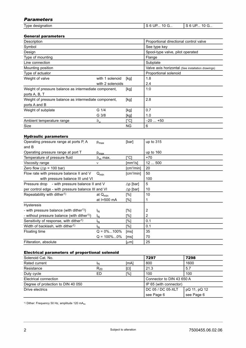
Type designation S 6 UP... 10 G... S 6 UP... 10 G...
General parametersDescription Proportional directional control valve
Symbol See type key
Design Spool-type valve, pilot operated
Type of mounting Flange
Line connection Subplate
Mounting position Valve axis horizontal (See installation drawings)
Type of actuator Proportional solenoid
Weight of valve with 1 solenoid [kg] 1.8
with 2 solenoids 2.4
Weight of pressure balance as intermediate component, [kg] 1:0
ports A, B, T
Weight of pressure balance as intermediate component, [kg] 2.8
ports A and B
Weight of subplate G 1/4 [kg] 0.7
G 3/8 [kg] 1.0
Ambient temperature range ϑu [°C] –20 ... +50
Size NG 6
Hydraulic parametersOperating pressure range at ports P, A pmax [bar] up to 315
and B
Operating pressure range at port T pmax up to 160
Temperature of pressure fluid ϑm max. [°C] +70
Viscosity range ν [mm2/s] 12 ... 500
Zero flow (Vp = 100 bar) [cm3/min] 20
Flow rate with pressure balance II and V Qmin [cm3/min] 50
with pressure balance III und VI 100
Pressure drop - with pressure balance II and V Vp [bar] 5
per control edge - with pressure balance III and VI Vp [bar] 10
Repeatability with dither1) at Qmin [%] 10
at I=500 mA [%] 1
Hysteresis
- with pressure balance (with dither1)) IN [%] 2
- without pressure balance (with dither1)) IN [%] 2
Sensitivity of response, with dither1) IN [%] 0.1
Width of backlash, with dither1) IN [%] 0.1
Floating time Q = 0%...100% [ms] 35
Q = 100%...0% [ms] 70
Filteration, absolute [μm] 25
Electrical parameters of proportional solenoidSolenoid Cat. No. 7297 7298Rated current IN [mA] 800 1600
Resistance R20 [Ω] 21.3 5.7
Duty cycle ED [%] 100 100
Electrical connection Connector to DIN 43 650 A
Degree of protection to DIN 40 050 IP 65 (with connector)
Drive electrics DC 05 / DC 05-XLT pQ 11, pQ 12
see Page 6 see Page 6
1) Dither: Frequency 50 Hz, amplitude 120 mAss
2 7500455.06.02.06Subject to alteration
Parameters
37500455.06.02.06 Subject to alteration
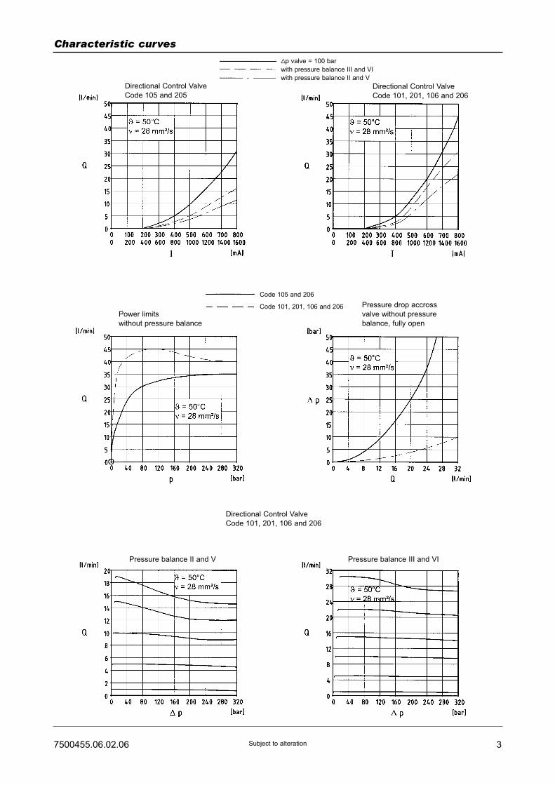
Characteristic curves
Vp valve = 100 bar
with pressure balance III and VI
with pressure balance II and V
Directional Control Valve
Code 101, 201, 106 and 206
Pressure drop accross
valve without pressure
balance, fully open
Power limits
without pressure balance
Code 105 and 206
Code 101, 201, 106 and 206
Directional Control Valve
Code 101, 201, 106 and 206
Directional Control Valve
Code 105 and 205
Pressure balance II and V Pressure balance III and VI

4 7500455.06.02.06Subject to alteration
Ordering Example of order
The units are designated by their type number. Thecomposition of this number can be drawn from the typecode. The standard versions are listed in the typesurvey. When ordering any of the standard versions,please state type number as well as catalog number topreclude possible misinterpretations.When inquiring about or ordering units not listed in ourtype survey of this publication, the type number madeup by you by means of the type code, however, will do.The corresponding catalog number will then be statedin our confirmation of order. O-rings are enclosed withflanged units. Pressure balance, subplate, drive electro-nics and mounting screws must be ordered separately.
Proportional directional control valve, size 6, for flangemounting, Symbol 187, with Code 205, pressure balan-ce, mating subplate G 1/4 and drive electronics.
Proportional directional control valve:Type: S 6 UP 10 G 187 205 4 O VCat. No.: 5204807.7298Pressure balance:Cat. No.: 6015190Subplate:Type: P S 6 G 2 024 2 O OCat. No.: 1065173Mounting screws: (4 pcs. required)Socket head screw (M 5 x 70 DIN 912-10.9)Cat. No.: 0662315Drive electronics to be ordered separately, see Page 6.
Installation drawing
Manual override
57500455.06.02.06 Subject to alteration
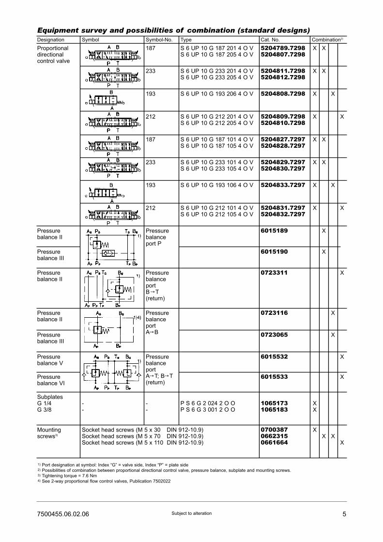
Equipment survey and possibilities of combination (standard designs)Designation Symbol Symbol-No. Type Cat. No. Combination2)
Proportionaldirectionalcontrol valve
187
233
193
212
187
233
193
212
S 6 UP 10 G 187 201 4 O VS 6 UP 10 G 187 205 4 O V
S 6 UP 10 G 233 201 4 O VS 6 UP 10 G 233 205 4 O V
S 6 UP 10 G 193 206 4 O V
S 6 UP 10 G 212 201 4 O VS 6 UP 10 G 212 205 4 O V
S 6 UP 10 G 187 101 4 O VS 6 UP 10 G 187 105 4 O V
S 6 UP 10 G 233 101 4 O VS 6 UP 10 G 233 105 4 O V
S 6 UP 10 G 193 106 4 O V
S 6 UP 10 G 212 101 4 O VS 6 UP 10 G 212 105 4 O V
5204789.72985204807.7298
5204811.72985204812.7298
5204808.7298
5204809.72985204810.7298
5204827.72975204828.7297
5204829.72975204830.7297
5204833.7297
5204831.72975204832.7297
Pressurebalanceport P
6015189
6015190
0723311
0723116
0723065
6015532
6015533
10651731065183
P S 6 G 2 024 2 O OP S 6 G 3 001 2 O O
070038706623150661664
PressurebalanceportB C T(return)
PressurebalanceportAC B
PressurebalanceportAC T; BC T(return)
--
--
Pressurebalance II
Pressurebalance III
Pressurebalance II
Pressurebalance II
Pressurebalance III
Pressurebalance V
Pressurebalance VI
SubplatesG 1/4G 3/8
Mountingscrews3)
Socket head screws (M 5 x 30 DIN 912-10.9)Socket head screws (M 5 x 70 DIN 912-10.9)Socket head screws (M 5 x 110 DIN 912-10.9)
X X
X X
X X
X X
X X
X X
X X
X X
X
X
X
X
X
X
X
XX
XX X
X
1) Port designation at symbol: Index “G” = valve side, Index “P” = plate side2) Possibilities of combination between proportional directional control valve, pressure balance, subplate and mounting screws.3) Tightening torque = 7.6 Nm4) See 2-way proportional flow control valves, Publication 7502022

6 7500455.06.02.06Subject to alteration
Drive electronics
Drive electronicsDC 05 / DC 05-XLTDigital amplifier with constant current
regulator PWM
Power supply: 18 ... 30 VDC,
incl. residual ripple
Ambient temperature ϑU: 0 ... +50 °C
Weight: 0,4 kg
Mounting position: Upright
Free air circulation must be ensured
Space requirement for installation of
19" card rack: 50 mm
European format: 100 x 160 mm
Type
For proportional directional control valvesRated current IN : 0 ... 1600 mA
7503503
7503504
Setpoint input
(switchable)
Internal
setpoints
Pcs.
Ramps
Pcs.
Terminal
strip
Form F
DIN 41612
Number
of pins
PID controller
for external
control loops
Cat. No. For Further
information,
see
script
44
4 2
48
48
51500001)
51500011)
� /�
(switchable)
�
DC 05 2 x 0...±10V
0...±10V
0(4)...20 mA
DC 05-XLT
[V] [mA]
Functional
compatible to
pQ 03
Drive electronics pQ 11Plug-in amplifier with constant current
regulator PWM
Degree of protection: IP 65
Power supply: 18 ... 32 VDC,
Residual ripple: ≤10 %
Ambient temperature ϑU: -20 ...+50 °C
Mounting position: Optional
Setpoint input
(switchable)
For proportional valves with 2 solenoids 2 pQ 11 necessaryRated current IN: 0 ... 2400 mA, allowed resistance of solenoid R20: 2,5...4,5 Ω
HERION
7502961
[mA][V]
Type of connection
Connecting
cable, 2 m
Connector acc. to
DIN 43651
Weight
[kg]
Cat. No. For Further
information,
see
script
0 ... 10
0 ... 10
0 (4)...20
0 (4)...20
�
�
�
�
5980085
59800811)
0,18
0,18
Mark in table: � without, � with1) Cable connector to be ordered separately. Cat. No. 0660689
1) Pre-parametrred electronics on request.
Drive electronics pQ 12Amplifier module with constant current
regulator PWM
Degree of protection: IP 65
Power supply: 18 ... 32 VDC,
Residual ripple: ≤10 %
Ambient temperature ϑU: -20 ...+50 °C
Mounting position: Optional
For attachment on mounting rail acc.
to EN 50022
Setpoint input
(switchable)
For proportional valves with 2 solenoids 2 pQ 11 necessary HERION
7503109
[mA] [mA][V]
Output currents Cat. No. For Furtherinformation,seescript
0 ... 10 0 (4)...20 0 ... 1600 / 2400 5980126

77500455.06.02.06 Subject to alteration
Dimensional drawings [mm]
Proportional directional control valve
S 6 UP 10 G 187 ... 4 O VS 6 UP 10 G 233 ... 4 O VS 6 UP 10 G 212 ... 4 O V
Proportional directional control valve with pressure balance in port P to B CT
S 6 UP 10 G 187 ... 4 O VS 6 UP 10 G 233 ... 4 O VS 6 UP 10 G 212 ... 4 O V
S 6 UP 10 G 193 ... 4 O V

8 7500455.06.02.06Subject to alteration
Proportional directional control valve pressure balance in port A CT to B CT (return flow)
S 6 UP 10 G 212 ... 4 O V
Proportional directional control valve in port A CB
S 6 UP 10 G 193 ... 4 O V
80
97500455.06.02.06 Subject to alteration
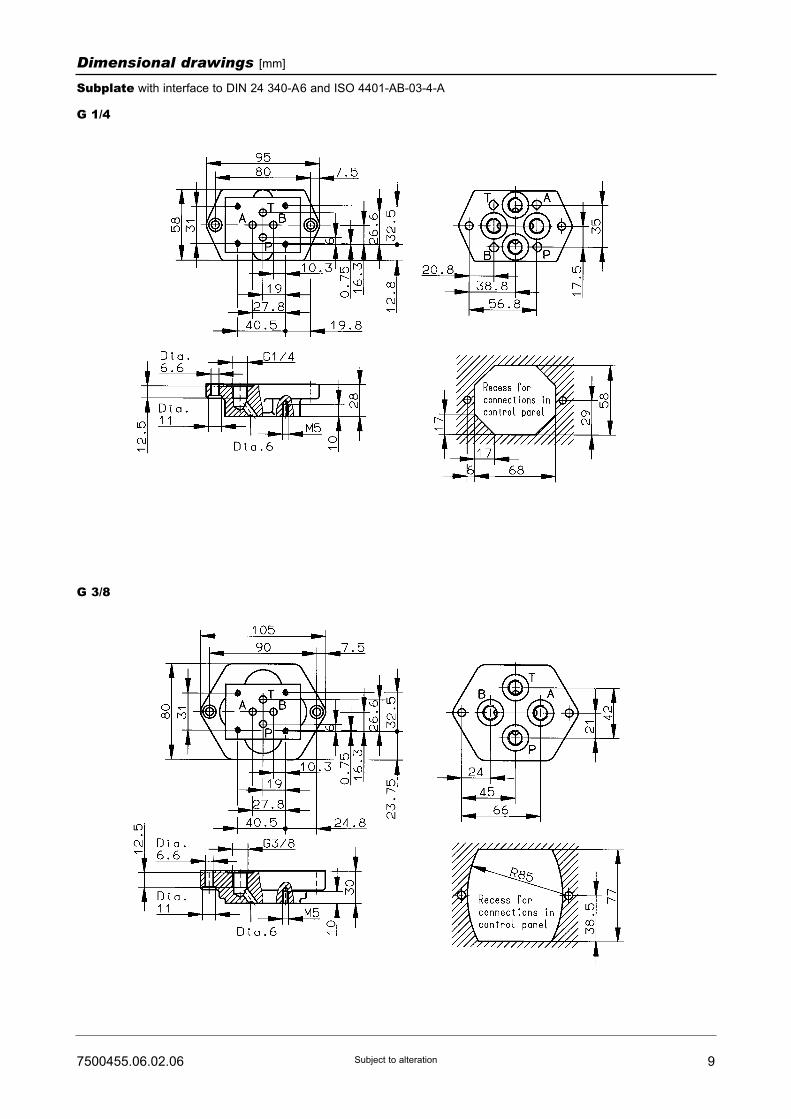
Dimensional drawings [mm]
Subplate with interface to DIN 24 340-A6 and ISO 4401-AB-03-4-A
G 1/4
G 3/8
10 7500455.06.02.06Subject to alteration
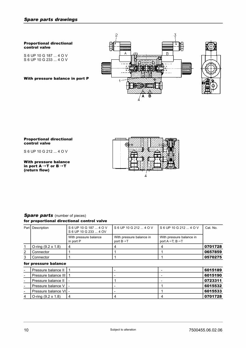
Spare parts drawings
Proportional directionalcontrol valve
S 6 UP 10 G 187 ... 4 O VS 6 UP 10 G 233 ... 4 O V
With pressure balance in port P
Proportional directionalcontrol valve
S 6 UP 10 G 212 ... 4 O V
With pressure balancein port A CT or B CT(return flow)
Spare parts (number of pieces)
for proportional directional control valve
Part
1
2
3
O-ring (9.2 x 1.8)
Connector
Connector
4
1
1
4
1
1
4
1
1
070172806578590570275
-
-
-
-
-
4
Pressure balance II
Pressure balance III
Pressure balance II
Pressure balance V
Pressure balance VI
O-ring (9.2 x 1.8)
1
1
-
-
-
4
-
-
1
-
-
4
-
-
-
1
1
4
601518960151900723311601553260155330701728
Description Cat. No.S 6 UP 10 G 187 ... 4 O V
S 6 UP 10 G 233 ... 4 OV
With pressure balance
in port P
S 6 UP 10 G 212 ... 4 O V
With pressure balance in
port B CT
With pressure balance in
port A CT; B CT
S 6 UP 10 G 212 ... 4 O V
for pressure balance

117500455.06.02.06 Subject to alteration
Spare parts (number of pieces)
for proportional directional control valve
Part
1
2
O-ring (9.2 x 1.8)
Connector
4
1
07017280657859
-
-
3
Pressure balance II
Pressure balance III
O-ring (9.2 x 1.8)
1
-
2
-
1
2
072311607230650701728
Description Cat. No.S 6 UP 10 G 193 ... 4 O V
Part Description Cat. No.Pressure balance II Pressure balance III
With plate type pressure balance
in port A
for pressure balance

Throttle Check ValvesSize 8, 10, 12, 16, 20 and 25For inline and switchboards installation
PN [pmax.] = 350 bar
7500718.06.01.06
ConstructionThe throttle check valve throttles the flow in onedirection A to B while allowing free passage in the otherdirection via the incorporated check valve (B to A). Thethrottling is effected by a longitudinal notch worked intothe adjusting spindle. The cross-sectional area of therestrictor is in a linear relation to the adjusting path. Thelast turn of the knob fully opens the passage.
ActuationAdjust flow means of the rotary knob. The colored scalemakes it easy to repeat the set values. The area of thecolored triangle indicates the size of the cross-sectionof the passage. A set screw prevents inadvertentadjustment.
MountingThe check valves are mounted inline or in switchboard.
Pipe connectionPorts threaded.
• fine adjustment thanks to the big rotary knob• when turning, rotary knob remains in the same height• good repeatability due to large range of adjustment
(10 turns)• easy reading from all sides
Description (standard units)
Features
Type keyThrottle check valveM U ... H R ... 001 ... O ...
1 2 3
1 Size: 1 181012162025
2 Pipe connection:Size 18: 2 - G 1/4Size 10: 3 - G 3/8Size 12: 4 - G 1/2 (Internal thread acc.Size 16: 5 - G 3/4 to DIN ISO 228/1)Size 20: 6 - G 1Size 25: 7 - G 1 1/4
3 Engineering version: 3
HERION Systemtechnik GmbHUntere Talstraße 65
D-71263 Weil der Stadt (Merklingen)
Tel.: +49 (0) 70 33/30 18-0
Fax: +49 (0) 70 33/30 18-10
www.herion-systemtechnik.de
2 7500718.06.01.06Subject to alteration
Characteristic curves
Type designation M U 8 ... M U 10 ... M U 12 ... M U 16 ... M U 20 ... M U 25 ...
General parametersDesignation Throttle check valve
Symbol
Construction V-shaped throttle
Type of mounting Thread
Pipe connection Threaded connection acc. to DIN 259 (pipe mounting)
Mounting position Any
Flow direction Throttle-function from A to BFree flow via check valve from B to A
Actuation By hand
Weight of throttle check valve [kg] 0.3 0.45 0.8 1.3 2.4 3.5
Ambienttemperature ϑu [°C] –20 to +50
Size 8 10 12 16 20 25
Hydraulic parametersOperating pressure range pe [bar] 0 to 350
Opening pressure pö [bar] 0.5
Pressure fluid temperature ϑm max. [°C] + 100
Viscosity ν [mm2/s] 12 to 500
Flow Q [l/min] See characteristic curves
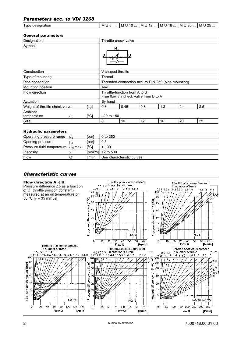
Parameters acc. to VDI 3268
Flow direction A Q BPressure difference Vp as a functionof Q (throttle position constant),measured at an oil temperature of50 °C [ν = 35 mm2/s]
37500718.06.01.06 Subject to alteration
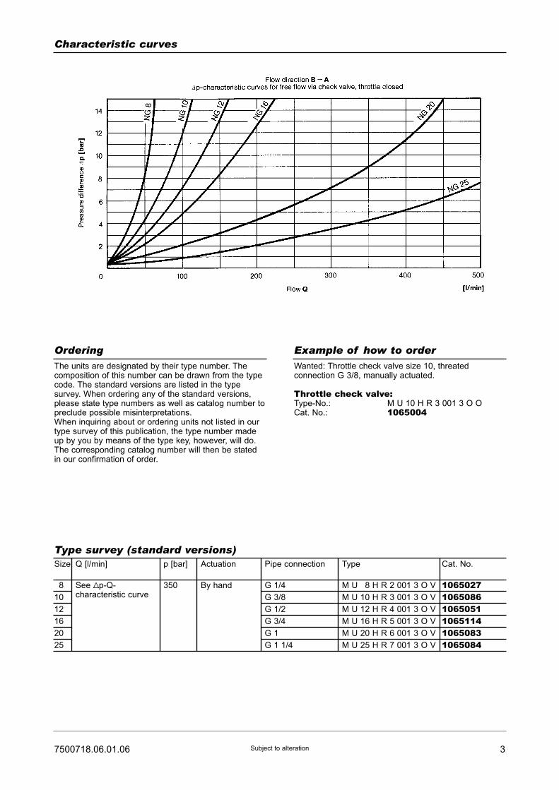
The units are designated by their type number. Thecomposition of this number can be drawn from the typecode. The standard versions are listed in the typesurvey. When ordering any of the standard versions,please state type numbers as well as catalog number topreclude possible misinterpretations.When inquiring about or ordering units not listed in ourtype survey of this publication, the type number madeup by you by means of the type key, however, will do.The corresponding catalog number will then be statedin our confirmation of order.
Wanted: Throttle check valve size 10, threatedconnection G 3/8, manually actuated.
Throttle check valve:Type-No.: M U 10 H R 3 001 3 O OCat. No.: 1065004
Ordering
Type survey (standard versions)
Example of how to order
Size
18
10
12
16
20
25
Q [l/min]
See Vp-Q-characteristic curve
p [bar]
350
Pipe connection
G 1/4
G 3/8
G 1/2
G 3/4
G 1
G 1 1/4
Actuation
By hand
Type
M U 18 H R 2 001 3 O V
M U 10 H R 3 001 3 O V
M U 12 H R 4 001 3 O V
M U 16 H R 5 001 3 O V
M U 20 H R 6 001 3 O V
M U 25 H R 7 001 3 O V
Cat. No.
106502710650861065051106511410650831065084
Characteristic curves
Part Designation Size Size Size Size Size Size Cat. No.8 10 12 16 20 25
1 O-ring (2.9 x 1.8) 1 - - - - - 07012461 O-ring (4.5 x 1.8) - 1 - - - - 07012481 O-ring (5.3 x 2.4) - - 1 - - - 06616391 O-ring (7.3 x 2.4) - - - 1 - - 06615961 O-ring (10.3 x 2.4) - - - - 1 1 06615972 Thrust ring 1 - - - - - 0661592
(SRA-6-1.45-1)
2 Thrust ring - 1 - - - - 0661593(SRA-8-1.45-1)
2 Thrust ring - - 1 - - - 0661640(SRA-10-2.05-1)
2 Thrust ring - - - 1 - - 0661594(SRA-12-2.05-1)
2 Thrust ring - - - - 1 1 0661595(SRA-15-2.05-1)
4 7500718.06.01.06Subject to alteration
Spare parts (numer of pieces)
Part Designation Size Size Size Size Size Size Cat. No.8 10 12 16 20 25
3 Spring 1 - - - - - 06616443 Spring - 1 - - - - 06616433 Spring - - 1 - - - 06616413 Spring - - - 1 - - 06616463 Spring - - - - 1 - 06616453 Spring - - - - - 1 0724257Set of spare parts1 set of spare parts 1 to 3 - - - - - 0721968consists of parts:
- 1 to 3 - - - - 0721969- - 1 to 3 - - - 0722025- - - 1 to 3 - - 0721970- - - - 1 to 3 - 0721971- - - - - 1 to 3 0724258
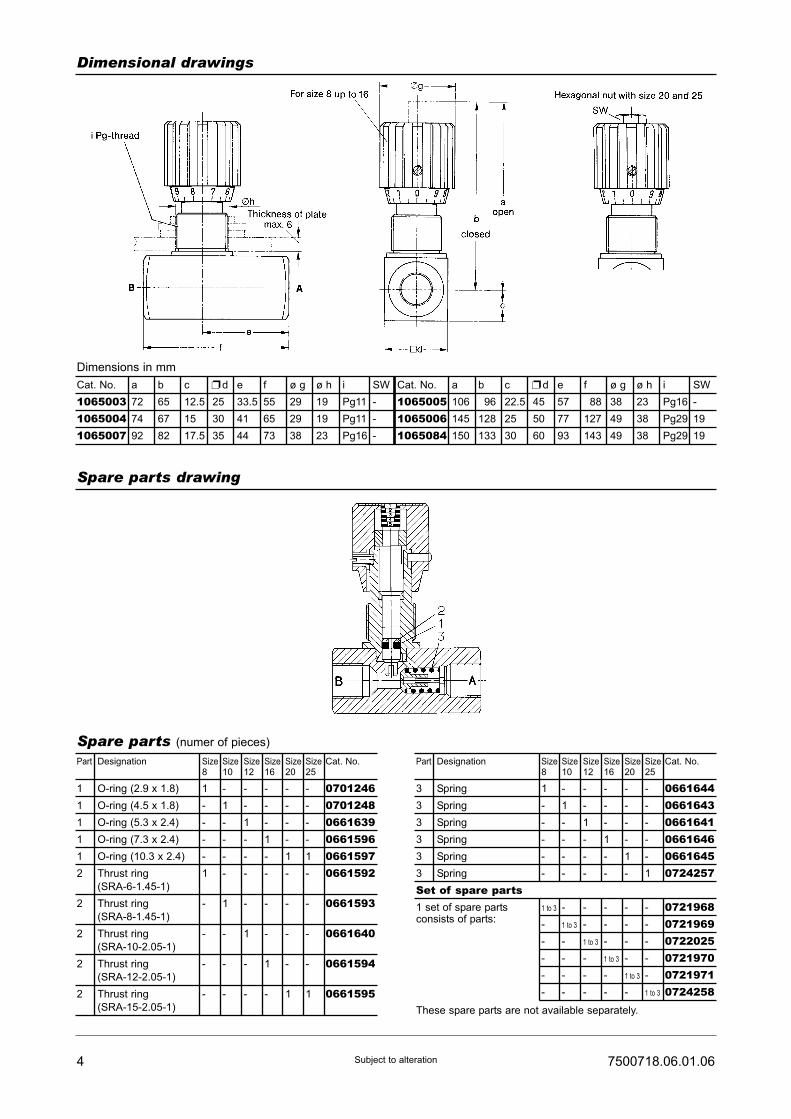
Dimensional drawings
Spare parts drawing
Cat. No. a b c d e f ø g ø h i SW
1065003 72 65 12.5 25 33.5 55 29 19 Pg11 -
1065004 74 67 15 30 41 65 29 19 Pg11 -
1065007 92 82 17.5 35 44 73 38 23 Pg16 -
:Cat. No. a b c d e f ø g ø h i SW
1065005 106 196 22.5 45 57 188 38 23 Pg16 -
1065006 145 128 25 50 77 127 49 38 Pg29 19
1065084 150 133 30 60 93 143 49 38 Pg29 19
:
These spare parts are not available separately.
Dimensions in mm

Throttle Check ValvesSize 8, 10, 12, 16, 20 and 25For inline and switchboards installation
PN [pmax.] = 350 bar
7500718.06.01.06
ConstructionThe throttle check valve throttles the flow in onedirection A to B while allowing free passage in the otherdirection via the incorporated check valve (B to A). Thethrottling is effected by a longitudinal notch worked intothe adjusting spindle. The cross-sectional area of therestrictor is in a linear relation to the adjusting path. Thelast turn of the knob fully opens the passage.
ActuationAdjust flow means of the rotary knob. The colored scalemakes it easy to repeat the set values. The area of thecolored triangle indicates the size of the cross-sectionof the passage. A set screw prevents inadvertentadjustment.
MountingThe check valves are mounted inline or in switchboard.
Pipe connectionPorts threaded.
• fine adjustment thanks to the big rotary knob• when turning, rotary knob remains in the same height• good repeatability due to large range of adjustment
(10 turns)• easy reading from all sides
Description (standard units)
Features
Type keyThrottle check valveM U ... H R ... 001 ... O ...
1 2 3
1 Size: 1 181012162025
2 Pipe connection:Size 18: 2 - G 1/4Size 10: 3 - G 3/8Size 12: 4 - G 1/2 (Internal thread acc.Size 16: 5 - G 3/4 to DIN ISO 228/1)Size 20: 6 - G 1Size 25: 7 - G 1 1/4
3 Engineering version: 3
HERION Systemtechnik GmbHUntere Talstraße 65
D-71263 Weil der Stadt (Merklingen)
Tel.: +49 (0) 70 33/30 18-0
Fax: +49 (0) 70 33/30 18-10
www.herion-systemtechnik.de

2 7500718.06.01.06Subject to alteration
Characteristic curves
Type designation M U 8 ... M U 10 ... M U 12 ... M U 16 ... M U 20 ... M U 25 ...
General parametersDesignation Throttle check valve
Symbol
Construction V-shaped throttle
Type of mounting Thread
Pipe connection Threaded connection acc. to DIN 259 (pipe mounting)
Mounting position Any
Flow direction Throttle-function from A to BFree flow via check valve from B to A
Actuation By hand
Weight of throttle check valve [kg] 0.3 0.45 0.8 1.3 2.4 3.5
Ambienttemperature ϑu [°C] –20 to +50
Size 8 10 12 16 20 25
Hydraulic parametersOperating pressure range pe [bar] 0 to 350
Opening pressure pö [bar] 0.5
Pressure fluid temperature ϑm max. [°C] + 100
Viscosity ν [mm2/s] 12 to 500
Flow Q [l/min] See characteristic curves
Parameters acc. to VDI 3268
Flow direction A Q BPressure difference Vp as a functionof Q (throttle position constant),measured at an oil temperature of50 °C [ν = 35 mm2/s]

37500718.06.01.06 Subject to alteration
The units are designated by their type number. Thecomposition of this number can be drawn from the typecode. The standard versions are listed in the typesurvey. When ordering any of the standard versions,please state type numbers as well as catalog number topreclude possible misinterpretations.When inquiring about or ordering units not listed in ourtype survey of this publication, the type number madeup by you by means of the type key, however, will do.The corresponding catalog number will then be statedin our confirmation of order.
Wanted: Throttle check valve size 10, threatedconnection G 3/8, manually actuated.
Throttle check valve:Type-No.: M U 10 H R 3 001 3 O OCat. No.: 1065004
Ordering
Type survey (standard versions)
Example of how to order
Size
18
10
12
16
20
25
Q [l/min]
See Vp-Q-characteristic curve
p [bar]
350
Pipe connection
G 1/4
G 3/8
G 1/2
G 3/4
G 1
G 1 1/4
Actuation
By hand
Type
M U 18 H R 2 001 3 O V
M U 10 H R 3 001 3 O V
M U 12 H R 4 001 3 O V
M U 16 H R 5 001 3 O V
M U 20 H R 6 001 3 O V
M U 25 H R 7 001 3 O V
Cat. No.
106502710650861065051106511410650831065084
Characteristic curves

Part Designation Size Size Size Size Size Size Cat. No.8 10 12 16 20 25
1 O-ring (2.9 x 1.8) 1 - - - - - 07012461 O-ring (4.5 x 1.8) - 1 - - - - 07012481 O-ring (5.3 x 2.4) - - 1 - - - 06616391 O-ring (7.3 x 2.4) - - - 1 - - 06615961 O-ring (10.3 x 2.4) - - - - 1 1 06615972 Thrust ring 1 - - - - - 0661592
(SRA-6-1.45-1)
2 Thrust ring - 1 - - - - 0661593(SRA-8-1.45-1)
2 Thrust ring - - 1 - - - 0661640(SRA-10-2.05-1)
2 Thrust ring - - - 1 - - 0661594(SRA-12-2.05-1)
2 Thrust ring - - - - 1 1 0661595(SRA-15-2.05-1)
4 7500718.06.01.06Subject to alteration
Spare parts (numer of pieces)
Part Designation Size Size Size Size Size Size Cat. No.8 10 12 16 20 25
3 Spring 1 - - - - - 06616443 Spring - 1 - - - - 06616433 Spring - - 1 - - - 06616413 Spring - - - 1 - - 06616463 Spring - - - - 1 - 06616453 Spring - - - - - 1 0724257Set of spare parts1 set of spare parts 1 to 3 - - - - - 0721968consists of parts:
- 1 to 3 - - - - 0721969- - 1 to 3 - - - 0722025- - - 1 to 3 - - 0721970- - - - 1 to 3 - 0721971- - - - - 1 to 3 0724258
Dimensional drawings
Spare parts drawing
Cat. No. a b c d e f ø g ø h i SW
1065003 72 65 12.5 25 33.5 55 29 19 Pg11 -
1065004 74 67 15 30 41 65 29 19 Pg11 -
1065007 92 82 17.5 35 44 73 38 23 Pg16 -
:Cat. No. a b c d e f ø g ø h i SW
1065005 106 196 22.5 45 57 188 38 23 Pg16 -
1065006 145 128 25 50 77 127 49 38 Pg29 19
1065084 150 133 30 60 93 143 49 38 Pg29 19
:
These spare parts are not available separately.
Dimensions in mm

2-way flow control valvesNG 6
with jump start suppressionInterface to DIN 24 340 and ISO
PN [pmax.] = 315 bar 7500990.06.02.06
DesignControl function from A to B by means of two restrictorsconnected in series - a variable throttle (differentialpressure piston) in front of a fixed restrictor (orifice).Due to the triangle-shaped cross section of the throttleit is possible to regulate even small streams of oil.Efficient suppression of jumping starts:The restrictors are axially arranged and work in thesame direction against the regulating spring. With noflow passing through the valve there is a fixed aspectratio between the two restrictors. This ratio keeps thethrottled area of the differential pressure piston fromopening more than absolutely necessary.
ActuationThe flow is set by hand, or by roller rocker. The settingcan, if desired, be safeguarded by means of locking(E 10-closure).
MountingThe units are bolted on subplates and sealed byO-rings.
Line connectionSubplate, interface to DIN 24 340 and ISO.
• Jump start suppression (standard)• Regulating range from 20 up to 16000 cm3/min
with an inlet pressure range from 5 to 315 bar• Space saving, vertical mounting on subplate• Incorporated by-pass check-valve
Description (standard units)
Features
Type codeFlow control valveM ... 6 ... G ... 001 ... O ...
1 2 3 4 5
SubplateP S 6 G ... ... ... O O
1 2 3
1 Operating: RU – Regulator (2-way)characteristics: with check-valve
2 Actuation: H – By handHV – By hand, lockableR – By roller rocker
3 Flow rate: 1 – 12 l/min2 – 14 l/min3 – 18 l/min4 – 16 l/min024 – 24 l/min
4 Engineering version: 15 Sealing material: V – Viton
1 Line connection: 2 – G 1/4 (Internal thread3 – G 3/8 to DIN ISO
228/1)
2 Code No.: 024 – G 1/4001 – G 3/8
3 Engineering version: 2
HERION Systemtechnik GmbHUntere Talstraße 65
D-71263 Weil der Stadt-Merklingen
Tel.: +49 (0) 70 33/30 18-0
Fax: +49 (0) 70 33/30 18-10
www.herion-systemtechnik.de
2 7500990.06.02.06Subject to alteration
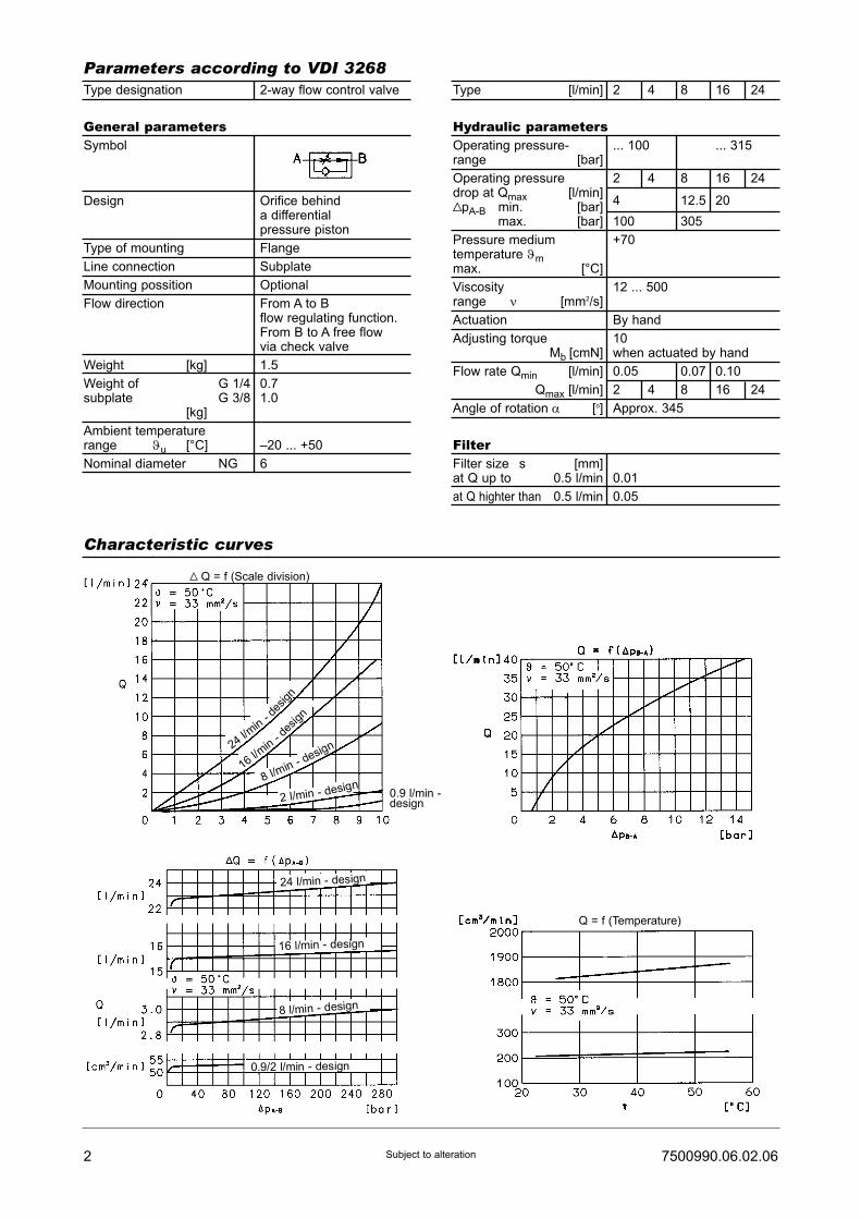
Type designation 2-way flow control valve
General parametersSymbol
Design Orifice behinda differentialpressure piston
Type of mounting Flange
Line connection Subplate
Mounting possition Optional
Flow direction From A to Bflow regulating function.From B to A free flowvia check valve
Weight [kg] 1.5
Weight of G 1/4 0.7subplate G 3/8 1.0
[kg]
Ambient temperaturerange ϑu [°C] –20 ... +50
Nominal diameterν NG 6
Parameters according to VDI 3268
Characteristic curves
Type [l/min] 2 4 8 16 24
Hydraulic parametersOperating pressure- ... 100 ... 315range [bar]
Operating pressure 2 4 8 16 24drop at Qmax [l/min]VpA-B min. [bar]
4 12.5 20
max. [bar] 100 305
Pressure medium +70temperature ϑmmax. [°C]
Viscosity 12 ... 500range ν [mm2/s]
Actuation By hand
Adjusting torque 10Mb [cmN] when actuated by hand
Flow rate Qmin [l/min] 0.05 0.07 0.10
Qmax [l/min] 2 4 8 16 24
Angle of rotation α [o] Approx. 345
FilterFilter size s [mm]at Q up to 0.5 l/min 0.01
at Q highter than 0.5 l/min 0.05
V Q = f (Scale division)
24l/m
in- de
sign
16l/m
in- de
sign
8 l/min - design
2 l/min - design0.9 l/min -design
Q = f (Temperature)
24 l/min - design
16 l/min - design
8 l/min - design
0.9/2 l/min - design
37500990.06.02.06 Subject to alteration
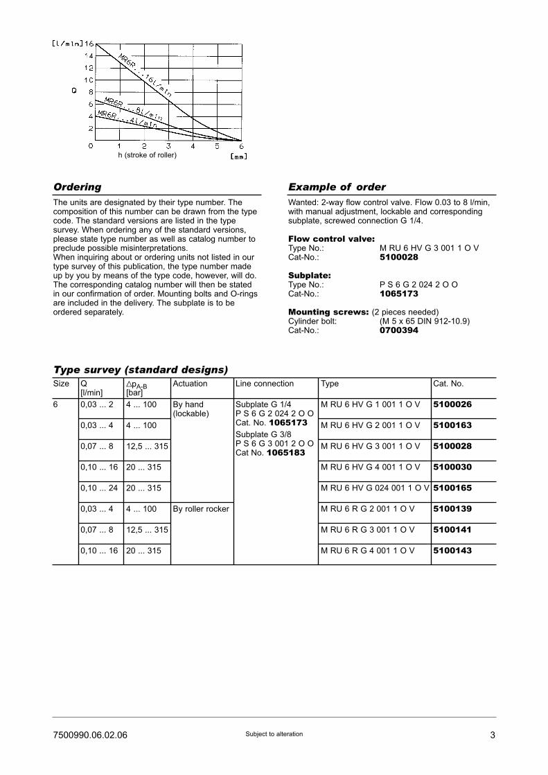
The units are designated by their type number. Thecomposition of this number can be drawn from the typecode. The standard versions are listed in the typesurvey. When ordering any of the standard versions,please state type number as well as catalog number topreclude possible misinterpretations.When inquiring about or ordering units not listed in ourtype survey of this publication, the type number madeup by you by means of the type code, however, will do.The corresponding catalog number will then be statedin our confirmation of order. Mounting bolts and O-ringsare included in the delivery. The subplate is to beordered separately.
Wanted: 2-way flow control valve. Flow 0.03 to 8 l/min,with manual adjustment, lockable and correspondingsubplate, screwed connection G 1/4.
Flow control valve:Type No.: M RU 6 HV G 3 001 1 O VCat-No.: 5100028
Subplate:Type No.: P S 6 G 2 024 2 O OCat-No.: 1065173
Mounting screws: (2 pieces needed)Cylinder bolt: (M 5 x 65 DIN 912-10.9)Cat-No.: 0700394
Ordering
Type survey (standard designs)
Example of order
Size
6
Q[l/min]
0,03 ... 2
0,03 ... 4
0,07 ... 8
0,10 ... 16
0,10 ... 24
0,03 ... 4
0,07 ... 8
0,10 ... 16
VpA-B[bar]
4 ... 100
4 ... 100
12,5 ... 315
20 ... 315
20 ... 315
4 ... 100
12,5 ... 315
20 ... 315
Actuation
By hand(lockable)
By roller rocker
Line connection
Subplate G 1/4P S 6 G 2 024 2 O OCat. No. 1065173Subplate G 3/8P S 6 G 3 001 2 O OCat No. 1065183
Type
M RU 6 HV G 1 001 1 O V
M RU 6 HV G 2 001 1 O V
M RU 6 HV G 3 001 1 O V
M RU 6 HV G 4 001 1 O V
M RU 6 HV G 024 001 1 O V
M RU 6 R G 2 001 1 O V
M RU 6 R G 3 001 1 O V
M RU 6 R G 4 001 1 O V
Cat. No.
5100026
5100163
5100028
5100030
5100165
5100139
5100141
5100143
h (stroke of roller)

4 7500990.06.02.06Subject to alteration
Dimensional drawings
Flow regulating valve
SubplateG 1/4
SubplateG 3/8
For corresponding plate-type rectifying unit, see 7500991
View A
Recess for
connections in
control panel
Recess for
connections in
control panel

57500990.06.02.06 Subject to alteration
Spare parts drawings
M RU 6 R G 2..M RU 6 R G 3..M RU 6 R G 4..
Note:The surface onto which the rectifying unit is to be flanged must not contain any other bores than those needed forconnection and fastening of the valve.
M RU 6 HV G 1..M RU 6 HV G 024..M RU 6 HV G 3..M RU 6 HV G 4..

6 7500990.06.02.06Subject to alteration
Designation
O-ring (9.2 x 1.8)
O-ring (12.4 x 1.8)
O-ring (18.7 x 1.8)
O-ring (2.8 x 1.6)
O-ring (20.3 x 1.8)
Seal part (10 x 18 x 7)
O-ring (7.66 x 1.78)
Pressure spring
Pressure spring
Pressure spring
Check valve
Stop screw
Pressure spring
Lock with key
Key
Part
1
2
3
4
5
5
6
7
8
8
9
10
10
11
12
Spare parts (Number of pieces)
M R
6 H
V G
2 .
.
M R
6 H
V G
1 .
.
Cat. No.
070172807016230701627065748307012590701017070162107217250721723072172406589370498749072590905685190660051
M R
U 6
HV
G 2
..
M R
U 6
HV
G 1
..
M R
6 H
V G
3 .
.
M R
6 H
V G
4 .
.
M R
6 H
V G
02
4 .
.
M R
U 6
HV
G 3
..
M R
U 6
HV
G 4
..
M R
U 6
HV
G 0
24
..
M R
6 R
G 2
..
M R
U 6
R G
2 .
.
M R
6 R
G 3
..
M R
6 R
G 4
..
M R
U 6
R G
3 .
.
M R
U 6
R G
4 .
.
2
3
1
1
1
-
-
1
1
-
-
1
-
1
1
2
3
1
1
1
-
1
1
1
-
1
1
-
1
1
2
3
1
1
1
-
-
1
-
1
-
1
-
1
1
2
3
1
1
1
-
1
1
-
1
1
1
-
1
1
2
3
1
1
-
1
-
1
1
-
-
-
1
-
-
2
3
1
-
-
1
1
1
1
-
1
-
1
-
-
2
3
1
1
-
1
-
1
-
1
-
-
1
-
-
2
3
1
-
-
1
1
1
-
1
1
-
1
-
-
Cylinder bolt(M5 x 65 DIN 912-10.9)
4 4 4 4 4 4 4 4 0700394Mounting bolts
-
1 Set of spare partsconsists of parts: 1 ... 5
1 ... 6
1 ... 5
1 ... 6
1
-
-
-
-
1
-
-
1
-
-
-
-
1
-
-
-
-
1
-
-
-
-
1
-
-
1
-
-
-
-
1
0726556072655807265600726562
Set of spare parts
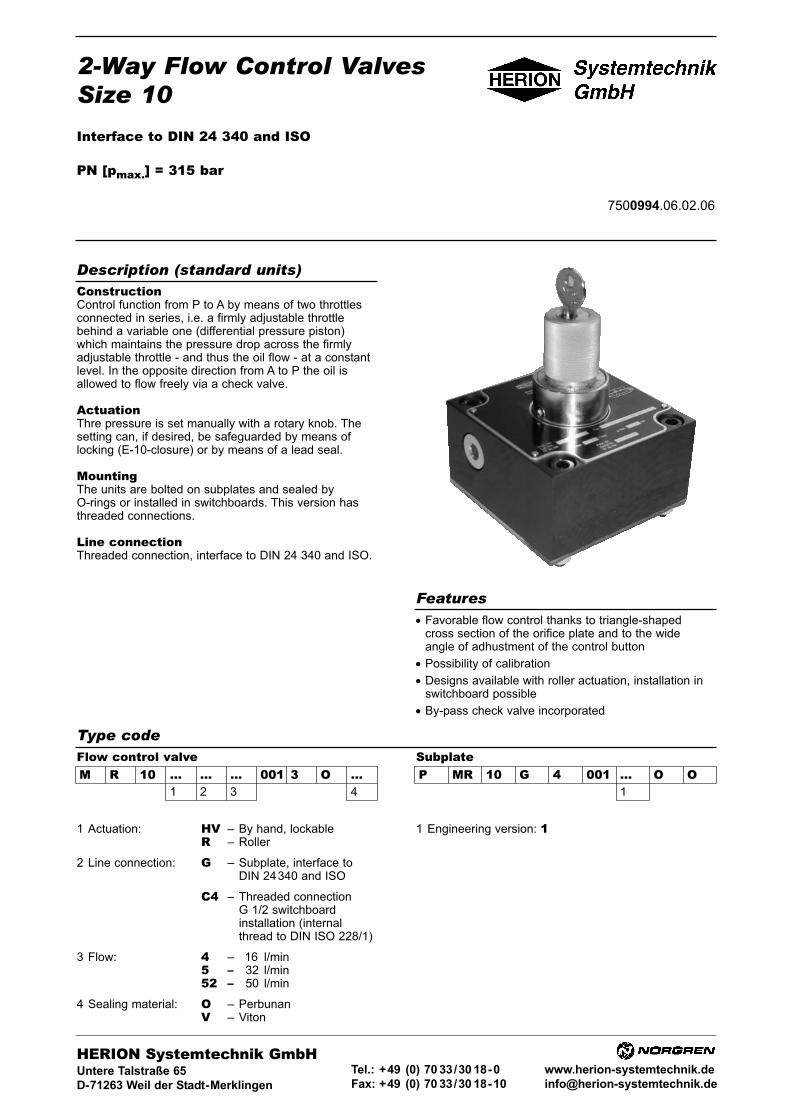
2-Way Flow Control ValvesSize 10
Interface to DIN 24 340 and ISO
PN [pmax.] = 315 bar
7500994.06.02.06
ConstructionControl function from P to A by means of two throttlesconnected in series, i.e. a firmly adjustable throttlebehind a variable one (differential pressure piston)which maintains the pressure drop across the firmlyadjustable throttle - and thus the oil flow - at a constantlevel. In the opposite direction from A to P the oil isallowed to flow freely via a check valve.
ActuationThre pressure is set manually with a rotary knob. Thesetting can, if desired, be safeguarded by means of locking (E-10-closure) or by means of a lead seal.
MountingThe units are bolted on subplates and sealed byO-rings or installed in switchboards. This version hasthreaded connections.
Line connectionThreaded connection, interface to DIN 24 340 and ISO.
• Favorable flow control thanks to triangle-shapedcross section of the orifice plate and to the wideangle of adhustment of the control button
• Possibility of calibration
• Designs available with roller actuation, installation inswitchboard possible
• By-pass check valve incorporated
Description (standard units)
Features
Type codeFlow control valveM R 10 ... ... ... 001 3 O ...
1 2 3 4
SubplateP MR 10 G 4 001 ... O O
1
1 Actuation: HV – By hand, lockableR – Roller
2 Line connection: G – Subplate, interface toDIN 24340 and ISO
C4 – Threaded connectionG 1/2 switchboardinstallation (internalthread to DIN ISO 228/1)
3 Flow: 4 – 116 l/min5 – 132 l/min52 – 150 l/min
4 Sealing material: O – PerbunanV – Viton
1 Engineering version: 1
HERION Systemtechnik GmbHUntere Talstraße 65
D-71263 Weil der Stadt-Merklingen
Tel.: +49 (0) 70 33/30 18-0
Fax: +49 (0) 70 33/30 18-10
www.herion-systemtechnik.de
2 7500994.06.02.06Subject to alteration
Type designation 2-way flow control valve
General parametersSymbol
Design Orifice plate-typethrottle behind differentialpressure piston
Type of mounting Flange
Line connection Subplate
Mounting position Optional
Flow direction P to Aflow control functionA to Pfree flow via check valve
Weight [kg] 3.8
Weight ofsubplate [kg] 2
Ambient temperaturerange ϑu [°C] –20 ... +50
Size ν [NG] 10
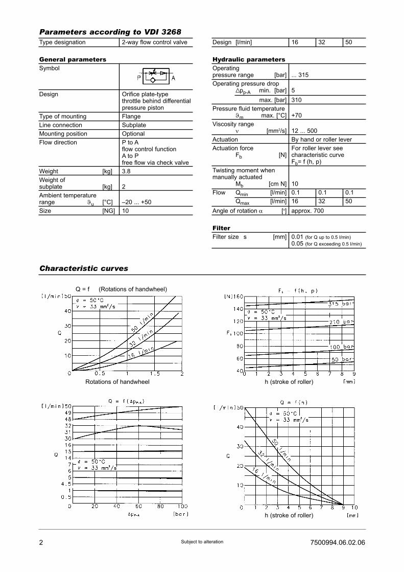
Parameters according to VDI 3268
Characteristic curves
Design [l/min] 16 32 50
Hydraulic parametersOperatingpressure range [bar] ... 315
Operating pressure dropVpp-A min. [bar] 5
max. [bar] 310
Pressure fluid temperatureϑm max. [°C] +70
Viscosity rangeν [mm2/s] 12 ... 500
Actuation By hand or roller lever
Actuation force For roller lever seeFb [N] characteristic curve
Fb= f (h, p)
Twisting moment whenmanually actuated
Mb [cm N] 10
Flow Qmin [l/min] 0.1 0.1 0.1
Qmax [l/min] 16 32 50
Angle of rotation α [o] approx. 700
FilterFilter size s [mm] 0.01 (for Q up to 0.5 l/min)
0.05 (for Q exceeding 0.5 l/min)
Q = f (Rotations of handwheel)
Rotations of handwheel h (stroke of roller)
h (stroke of roller)
37500994.06.02.06 Subject to alteration
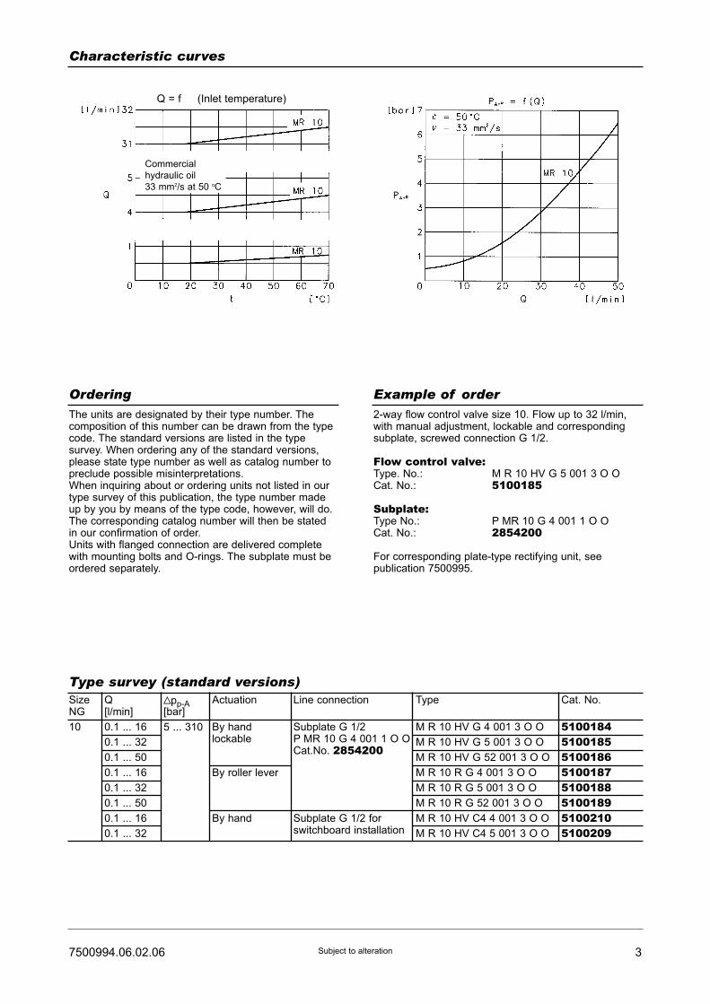
The units are designated by their type number. Thecomposition of this number can be drawn from the typecode. The standard versions are listed in the typesurvey. When ordering any of the standard versions,please state type number as well as catalog number topreclude possible misinterpretations.When inquiring about or ordering units not listed in ourtype survey of this publication, the type number madeup by you by means of the type code, however, will do.The corresponding catalog number will then be statedin our confirmation of order.Units with flanged connection are delivered completewith mounting bolts and O-rings. The subplate must beordered separately.
2-way flow control valve size 10. Flow up to 32 l/min,with manual adjustment, lockable and correspondingsubplate, screwed connection G 1/2.
Flow control valve:Type. No.: M R 10 HV G 5 001 3 O OCat. No.: 5100185
Subplate:Type No.: P MR 10 G 4 001 1 O OCat. No.: 2854200
For corresponding plate-type rectifying unit, seepublication 7500995.
Ordering
Type survey (standard versions)
Example of order
SizeNG
10
Q[l/min]
0.1 ... 16
0.1 ... 32
0.1 ... 50
0.1 ... 16
0.1 ... 32
0.1 ... 50
0.1 ... 16
0.1 ... 32
Vpp-A[bar]
5 ... 310
Actuation
By handlockable
By roller lever
By hand
Line connection
Subplate G 1/2P MR 10 G 4 001 1 O OCat.No. 2854200
Subplate G 1/2 forswitchboard installation
Type
M R 10 HV G 4 001 3 O O
M R 10 HV G 5 001 3 O O
M R 10 HV G 52 001 3 O O
M R 10 R G 4 001 3 O O
M R 10 R G 5 001 3 O O
M R 10 R G 52 001 3 O O
M R 10 HV C4 4 001 3 O O
M R 10 HV C4 5 001 3 O O
Cat. No.
51001845100185510018651001875100188510018951002105100209
Characteristic curves
Q = f (Inlet temperature)
Commercial
hydraulic oil
33 mm2/s at 50 oC

4 7500994.06.02.06Subject to alteration
Dimensional drawings
Flow regulation valvesM R 10 HV ...
M R 10 R ...
M R 10 HV C ... Recess in mounting wall
M8 x 55 DIN 912 - 10.9max. tightening torque 31 Nm
M8 x 55 DIN 912 - 10.9max. tightening torque 31 Nm
Str
oke

57500994.06.02.06 Subject to alteration
Dimensional drawings
SubplateG 1/2
Recess in mounting wall
6 7500994.06.02.06Subject to alteration
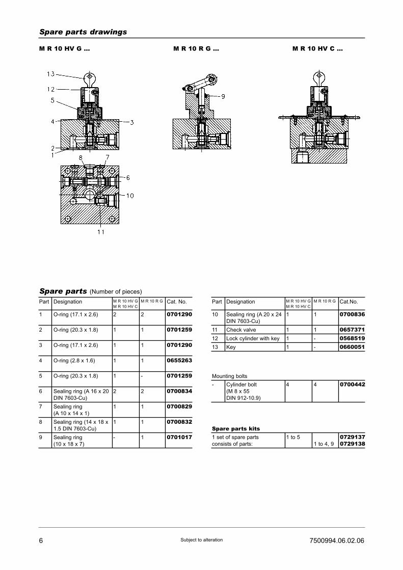
Spare parts drawings
M R 10 HV G ... M R 10 R G ... M R 10 HV C ...
DesignationPart
Spare parts (Number of pieces)
M R 10 HV G
M R 10 HV C
M R 10 R G Cat. No.
Cylinder bolt
(M 8 x 55
DIN 912-10.9)
- 4 4 0700442Mounting bolts
1 set of spare parts
consists of parts:
1 to 5
1 to 4, 9
07291370729138
Spare parts kits
O-ring (17.1 x 2.6)
O-ring (20.3 x 1.8)
O-ring (17.1 x 2.6)
O-ring (2.8 x 1.6)
O-ring (20.3 x 1.8)
Sealing ring (A 16 x 20
DIN 7603-Cu)
Sealing ring
(A 10 x 14 x 1)
Sealing ring (14 x 18 x
1.5 DIN 7603-Cu)
Sealing ring
(10 x 18 x 7)
2
1
1
1
1
2
1
1
-
2
1
1
1
-
2
1
1
1
1
2
3
4
5
6
7
8
9
0701290
0701259
0701290
0655263
0701259
0700834
0700829
0700832
0701017
DesignationPart M R 10 HV G
M R 10 HV C
M R 10 R G Cat.No.
Sealing ring (A 20 x 24
DIN 7603-Cu)
Check valve
Lock cylinder with key
Key
1
1
1
1
1
1
-
-
10
11
12
13
0700836
065737105685190660051
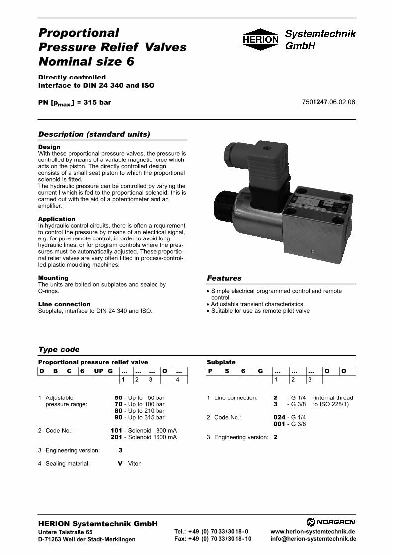
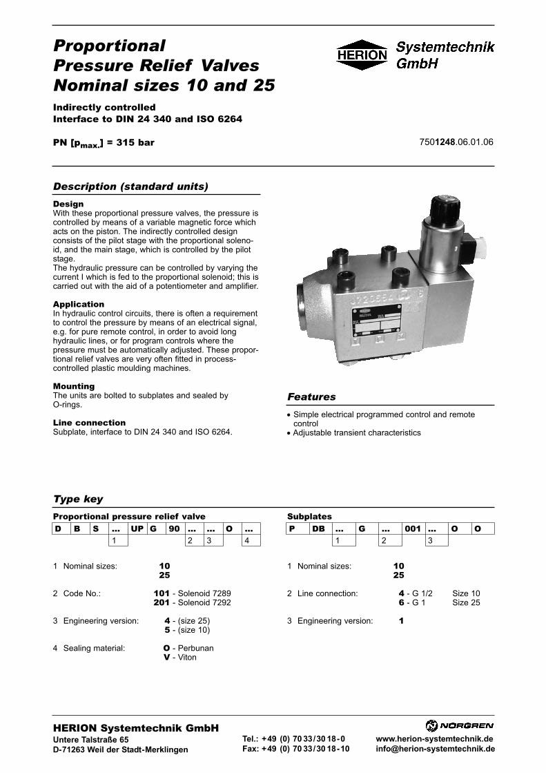
ProportionalPressure Relief ValvesNominal size 6Directly controlledInterface to DIN 24 340 and ISO
PN [pmax.] = 315 bar 7501247.06.02.06
DesignWith these proportional pressure valves, the pressure iscontrolled by means of a variable magnetic force whichacts on the piston. The directly controlled designconsists of a small seat piston to which the proportionalsolenoid is fitted.The hydraulic pressure can be controlled by varying thecurrent I which is fed to the proportional solenoid; this iscarried out with the aid of a potentiometer and anamplifier.
ApplicationIn hydraulic control circuits, there is often a requirementto control the pressure by means of an electrical signal,e.g. for pure remote control, in order to avoid longhydraulic lines, or for program controls where the pres-sures must be automatically adjusted. These proportio-nal relief valves are very often fitted in process-control-led plastic moulding machines.
MountingThe units are bolted on subplates and sealed byO-rings.
Line connectionSubplate, interface to DIN 24 340 and ISO.
• Simple electrical programmed control and remotecontrol
• Adjustable transient characteristics• Suitable for use as remote pilot valve
Description (standard units)
Features
Type code
D B C 6 UP G ... ... ... O ...1 2 3 4
SubplateProportional pressure relief valveP S 6 G ... ... ... O O
1 2 3
1 Adjustable 50 - Up to 150 barpressure range: 70 - Up to 100 bar
80 - Up to 210 bar90 - Up to 315 bar
2 Code No.: 101 - Solenoid 1800 mA201 - Solenoid 1600 mA
3 Engineering version: 3
4 Sealing material: V - Viton
1 Line connection: 200 - G 1/4 (internal thread300 - G 3/8 to ISO 228/1)
2 Code No.: 024 - G 1/4001 - G 3/8
3 Engineering version: 200
HERION Systemtechnik GmbHUntere Talstraße 65
D-71263 Weil der Stadt-Merklingen
Tel.: +49 (0) 70 33/30 18-0
Fax: +49 (0) 70 33/30 18-10
www.herion-systemtechnik.de

Type designation D B C 6 UP G... 101 3 O V D B C 6 UP G... 201 3 O V
General parametersDesignation Proportional pressure relief valve
Symbol
Design Seat valve, directly controlled
Type of mounting Flange
Line connection Subplate
Mounting position Free
Flow direction From P to T
Actuator Proportional solenoid
Weight of valve [kg] 1.7
Weight of subplate [kg] G 1/4 = 0.7
G 3/8 = 1.0
Ambient temperature ϑu [°C] –20 ... +50
Nominal size 6
Hydraulic parametersOperating pressure pe [bar] ... 315
Adjustable pressure range 1) pv [bar] pv min.: See characteristic curve1) pv max.: Pressure stage 50: ... 150
Pressure stage 70: ... 100
Pressure stage 80: ... 210
Pressure stage 90: ... 315
Pressure fluid temperature ϑmax. [°C] +70
Viscosity range ν [mm2/s] 12 ... 500
Flow Q [l/min] See characteristic curves
Regulating time for adjustable
pressure range from pv min. to pv max. [ms] Appr. 20
Hysteresis 2) [%IN] <3
Repeatability 2) [% pv max.]
Pressure stage 50 and 70: Appr. ±2
Pressure stage 80 and 90: Appr. ±1
Sensitivity of response 2) IN [%] <1
Filtering, absolute [μm] 25
Electrical parameters/Proportional solenoidSolenoid Cat. No. 7289 7292Rated current IN [mA] 800 1600
Nominal power input P20 [W] 14 14.6
Resistance R20 [Ω] 21.3 5.7
Duty cycle ED [%] 100 100
Protection class of solenoid and
electrical connection according to DIN 40 050 IP 65
Drive electronics DC 05 / DC 05-XLT see table page 5
pQ 11 und pQ 12 see table page 6
1) Smaller pv max. value can be set at ampliefier.2) With dither: Frequency 50 Hz, amplitude 15 % IN.
2 7501247.06.02.06Subject to alteration
Parameters to VDI 3276

37501247.06.02.06 Subject to alteration
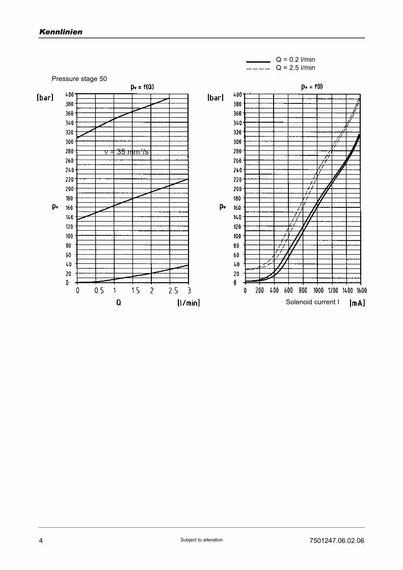
Characteristic curves
ν = 35 mm 2/s
ν = 35 mm 2/s
ν = 35 mm 2/s
Pressure stage 50
Pressure stage 70
Pressure stage 80
Solenoid current I
Solenoid current I
Solenoid current I
Q = 0.5 l/min
Q = 3 l/min
4 7501247.06.02.06Subject to alteration
Kennlinien
ν = 35 mm 2/s
Pressure stage 50
Solenoid current I
Q = 0.2 l/min
Q = 2.5 l/min

D B C 6 UP G 50 201 3 O V
D B C 6 UP G 70 201 3 O V
D B C 6 UP G 80 201 3 O V
D B C 6 UP G 90 201 3 O V
D B C 6 UP G 50 101 3 O V
D B C 6 UP G 70 101 3 O V
D B C 6 UP G 80 101 3 O V
D B C 6 UP G 90 101 3 O V
57501247.06.02.06 Subject to alteration
Ordering Example of order
The units are designated by their type number. Thecomposition of this number can be drawn from the typecode. The standard versions are listed in the typesurvey. When ordering any of the standard versions,please state type number as well as catalog number topreclude possible misinterpretations.When inquiring about or ordering units not listed in ourtype survey of this publication, the type number madeup by you by means of the type code, however, will do.The corresponding catalog number will then be statedin our confirmation of order. Mounting bolts and O-ringsare included in the delivery. The subplate, amplifier andsetpoint potentiometer are to be ordered separately.
Wanted: Propotional pressure relief valve, nominal size6, electrically-adjustable, for flanged mounting. Settingpressure max. 50 bar, with mating subplate.
Proportional pressure relief valve:Type-No.: D B C 6 UP G 50 201 3 O VCat. No.: 6016071.7292
Subplate G 1/4:Type-No.: P S 6 G 2 024 2 O OCat No.: 1065173
Drive electronics must be ordered separately.
Type survey (standard design)Nominal
size
6 50
100
210
315
50
100
210
315
0 ... 1600 mA
0 ... 800 mA
DC 05, DC 05-XLT,
pQ 11 or pQ 12
see table below
Subplate G 1/4
P S 6 G 2 024 2 OO
Cat. No. 1065173
Subplate G 3/8
P S 6 G 3 001 2 OO
Cat No. 1065183
6016071.7292
6016073.7292
6016075.7292
6016077.7292
6016072.72892)
6016074.72892)
6016076.72892)
6016078.72892)
pv max.
[bar]
Proportional
solenoid current
Drive
electronics
Line connection Type Cat. No.
Drive electronics
2) Not for new developments
Drive electronicsDC 05 / DC 05-XLTDigital amplifier with constant current
regulator PWM
Power supply: 18 ... 30 VDC,
incl. residual ripple
Ambient temperature ϑU: 0 ... +50 °C
Weight: 0,4 kg
Mounting position: Upright
Free air circulation must be ensured
Space requirement for installation of
19" card rack: 50 mm
European format: 100 x 160 mm
Type
For proportional directional control valvesRated current IN : 0 ... 1600 mA
7503503
7503504
Setpoint input
(switchable)
Internal
setpoints
Pcs.
Ramps
Pcs.
Terminal
strip
Form F
DIN 41612
Number
of pins
PID controller
for external
control loops
Cat. No. For Further
information,
see
script
44
4 2
48
48
51500001)
51500011)
� /�
(switchable)
�
DC 05 2 x 0...±10V
0...±10V
0(4)...20 mA
DC 05-XLT
[V] [mA]
Functional
compatible to
pQ 03
1) Pre-parametrred electronics on request.
6 7501247.06.02.06Subject to alteration
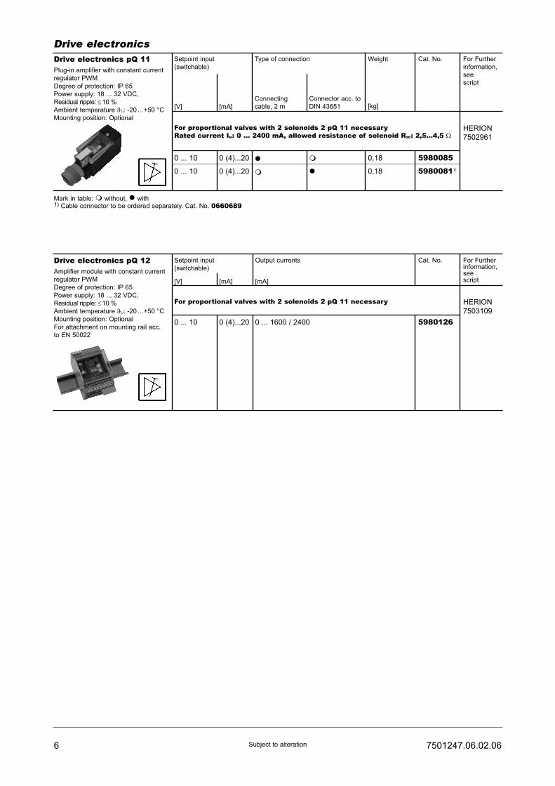
Drive electronicsDrive electronics pQ 11Plug-in amplifier with constant current
regulator PWM
Degree of protection: IP 65
Power supply: 18 ... 32 VDC,
Residual ripple: ≤10 %
Ambient temperature ϑU: -20 ...+50 °C
Mounting position: Optional
Setpoint input
(switchable)
For proportional valves with 2 solenoids 2 pQ 11 necessaryRated current IN: 0 ... 2400 mA, allowed resistance of solenoid R20: 2,5...4,5 Ω
HERION
7502961
[mA][V]
Type of connection
Connecting
cable, 2 m
Connector acc. to
DIN 43651
Weight
[kg]
Cat. No. For Further
information,
see
script
0 ... 10
0 ... 10
0 (4)...20
0 (4)...20
�
�
�
�
5980085
59800811)
0,18
0,18
Mark in table: � without, � with1) Cable connector to be ordered separately. Cat. No. 0660689
Drive electronics pQ 12Amplifier module with constant current
regulator PWM
Degree of protection: IP 65
Power supply: 18 ... 32 VDC,
Residual ripple: ≤10 %
Ambient temperature ϑU: -20 ...+50 °C
Mounting position: Optional
For attachment on mounting rail acc.
to EN 50022
Setpoint input
(switchable)
For proportional valves with 2 solenoids 2 pQ 11 necessary HERION
7503109
[mA] [mA][V]
Output currents Cat. No. For Furtherinformation,seescript
0 ... 10 0 (4)...20 0 ... 1600 / 2400 5980126
77501247.06.02.06 Subject to alteration
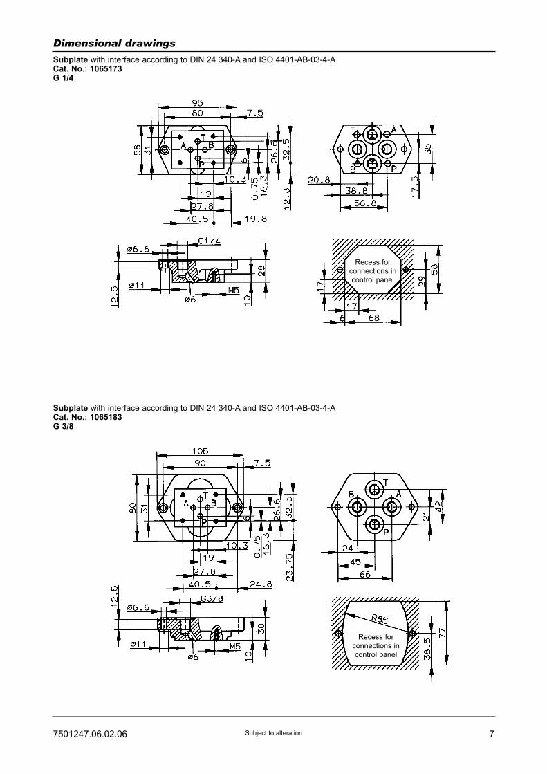
Dimensional drawings
Subplate with interface according to DIN 24 340-A and ISO 4401-AB-03-4-ACat. No.: 1065173G 1/4
Subplate with interface according to DIN 24 340-A and ISO 4401-AB-03-4-ACat. No.: 1065183G 3/8
Recess for
connections in
control panel
Recess for
connections in
control panel

8 7501247.06.02.06Subject to alteration
Dimensional drawings
Spare part drawing Spare parts / Accessories
Part
1 2 O-ring (10.8 x 1.8) 0701622
No. ofpcs.
Designation Cat. No.
Spare parts
- 1 Electrical connector 0570275
Accessories
- 4 Cylinder bolt(M5 x 45 DIN 912-10.9)Tightening torque MA = 7.6 Nm
0700390
Mounting bolts
Tightening torque
Appr. 7.6 Nm
Vent screw
Vent prior to putting into operation
(if solenoid is in horizontal position or
vertical on upside)
Automatical venting if solenoid
is on vertical downside position
Interface according to DIN 24 340-A6
and ISO 4401
ProportionalPressure Relief ValvesNominal sizes 10 and 25Indirectly controlledInterface to DIN 24 340 and ISO 6264
PN [pmax.] = 315 bar 7501248.06.01.06
DesignWith these proportional pressure valves, the pressure iscontrolled by means of a variable magnetic force whichacts on the piston. The indirectly controlled designconsists of the pilot stage with the proportional soleno-id, and the main stage, which is controlled by the pilotstage.The hydraulic pressure can be controlled by varying thecurrent I which is fed to the proportional solenoid; this iscarried out with the aid of a potentiometer and amplifier.
ApplicationIn hydraulic control circuits, there is often a requirementto control the pressure by means of an electrical signal,e.g. for pure remote control, in order to avoid longhydraulic lines, or for program controls where thepressure must be automatically adjusted. These propor-tional relief valves are very often fitted in process-controlled plastic moulding machines.
MountingThe units are bolted to subplates and sealed byO-rings.
Line connectionSubplate, interface to DIN 24 340 and ISO 6264.
• Simple electrical programmed control and remotecontrol
• Adjustable transient characteristics
Description (standard units)
Features
Type key
D B S ... UP G 90 ... ... O ...1 2 3 4
SubplatesProportional pressure relief valveP DB ... G ... 001 ... O O
1 2 3
1 Nominal sizes: 1025
2 Code No.: 101 - Solenoid 7289201 - Solenoid 7292
3 Engineering version: 4 - (size 25)5 - (size 10)
4 Sealing material: O - PerbunanV - Viton
1 Nominal sizes: 1025
2 Line connection: 4 - G 1/2 Size 106 - G 1 Size 25
3 Engineering version: 1
HERION Systemtechnik GmbHUntere Talstraße 65
D-71263 Weil der Stadt-Merklingen
Tel.: +49 (0) 70 33/30 18-0
Fax: +49 (0) 70 33/30 18-10
www.herion-systemtechnik.de
Type designation D B S 10 UP G... D B S 25 UP G...
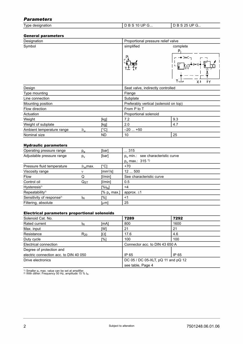
General parametersDesignation Proportional pressure relief valve
Symbol simplified complete
Design Seat valve, indirectly controlled
Type mounting Flange
Line connection Subplate
Mounting position Preferably vertical (solenoid on top)
Flow direction From P to T
Actuation Proportional solenoid
Weight [kg] 7.2 9.3
Weight of subplate [kg] 2.0 4.7
Ambient temperature range ϑu [°C] –20 ... +50
Nominal size ND 10 25
Hydraulic parametersOperating pressure range pe [bar] ... 315
Adjustable pressure range pv [bar] pv min.: see characteristic curve
pv max.: 315 1)
Pressure fluid temperature ϑmmax. [°C] +70
Viscosity range ν [mm2/s] 12 ... 500
Flow Q [l/min] See characteristic curve
Control oil QST [l/min] 0.5
Hysteresis2) [%IN] <4
Repeatability2) [% pv max.] approx. ±1
Sensitivity of response2) IN [%] <1
Filtering, absolute [μm] 25
Electrical parameters proportional solenoidsSolenoid Cat. No. 7289 7292Rated current IN [mA] 800 1600
Max. input [W] 21 21
Resistance R20 [Ω] 17.6 4.6
Duty cycle [%] 100 100
Electrical connection Connector acc. to DIN 43 650 A
Degree of protection and
electric connection acc. to DIN 40 050 IP 65 IP 65
Drive electronics DC 05 / DC 05-XLT, pQ 11 and pQ 12
see table, Page 4
1) Smaller pv max. value can be set at amplifier.2) With dither: Frequency 50 Hz, amplitude 15 % IN.
2 7501248.06.01.06Subject to alteration
Parameters

37501248.06.01.06 Subject to alteration
Characteristic curves
Ordering Example of order
The units are designated by their type number. Thecomposition of this number can be drawn from the typecode. The standard versions are listed in the typesurvey. When ordering any of the standard versions,please state type number as well as catalog number topreclude possible misinterpretations.When inquiring about or ordering units not listed in ourtype survey of this publication, the type number madeup by you by means of the type code, however, will do.The corresponding catalog number will then be statedin our confirmation of order. Mounting bolts and O-ringsare included in the delivery. The subplate, amplifier anddrive electronics are to be ordered separately.
Wanted: Proportional pressure relief valve nominal size10, electrically adjustable, for flanged mounting. Settingpressure range max. 315 bar, with mating subplate.Drive electronics to be ordered separately.
Proportional pressure relief valve:Type No.: D B S 10 UP G 90 201 5 O OCat. No. 6016060.7292.01200
Subplate:Type No.: P DB 10 G 4 001 1 O OCat No.: 2852600
D B S 10 UP G 90 201 5 O O
D B S 25 UP G 90 201 4 O O
D B S 10 UP G 90 101 5 O O
D B S 25 UP G 90 101 4 O O
Valve surveyNominal
size
10
25
10
25
315
315
0 ... 1600 mA
0 ... 800 mA
DC 05, DC 05-XLT
or pQ 11 or pQ 12
see table
Page 4
DC 05, DC 05-XLT
Subplate:
Nominal size 10, G 1/2
P DB 10 G 4 001 1 OO
Cat. No. 2852600
Nominal size 25, G 1
P DB 25 G 6 001 1 OO
Cat No. 2852400
6016060.7292.
01200
6016027.7292.
01200
6016061.7289.
02400
6016062.7289.
02400
pv max.
[bar]
Proportional
solenoid current
Drive electronics Line connection Type Cat No.
Note: Valve delivered with internal control oil return via YFor units with external control oil return via X, please observe instructions given in spare parts drawings
Solenoid current [mA] Q [l/min]

4 7501248.06.01.06Subject to alteration
Drive electronicsDrive electronicsDC 05 / DC 05-XLTDigital amplifier with constant current
regulator PWM
Power supply: 18 ... 30 VDC,
incl. residual ripple
Ambient temperature ϑU: 0 ... +50 °C
Weight: 0,4 kg
Mounting position: Upright
Free air circulation must be ensured
Space requirement for installation of
19" card rack: 50 mm
European format: 100 x 160 mm
Type
For proportional directional control valvesRated current IN : 0 ... 1600 mA
7503503
7503504
Setpoint input
(switchable)
Internal
setpoints
Pcs.
Ramps
Pcs.
Terminal
strip
Form F
DIN 41612
Number
of pins
PID controller
for external
control loops
Cat. No. For Further
information,
see
script
44
4 2
48
48
51500001)
51500011)
� /�
(switchable)
�
DC 05 2 x 0...±10V
0...±10V
0(4)...20 mA
DC 05-XLT
[V] [mA]
Functional
compatible to
pQ 03
Drive electronics pQ 11Plug-in amplifier with constant current
regulator PWM
Degree of protection: IP 65
Power supply: 18 ... 32 VDC,
Residual ripple: ≤10 %
Ambient temperature ϑU: -20 ...+50 °C
Mounting position: Optional
Setpoint input
(switchable)
For proportional valves with 2 solenoids 2 pQ 11 necessaryRated current IN: 0 ... 2400 mA, allowed resistance of solenoid R20: 2,5...4,5 Ω
HERION
7502961
[mA][V]
Type of connection
Connecting
cable, 2 m
Connector acc. to
DIN 43651
Weight
[kg]
Cat. No. For Further
information,
see
script
0 ... 10
0 ... 10
0 (4)...20
0 (4)...20
�
�
�
�
5980085
59800811)
0,18
0,18
Mark in table: � without, � with1) Cable connector to be ordered separately. Cat. No. 0660689
1) Pre-parametrred electronics on request.
Drive electronics pQ 12Amplifier module with constant current
regulator PWM
Degree of protection: IP 65
Power supply: 18 ... 32 VDC,
Residual ripple: ≤10 %
Ambient temperature ϑU: -20 ...+50 °C
Mounting position: Optional
For attachment on mounting rail acc.
to EN 50022
Setpoint input
(switchable)
For proportional valves with 2 solenoids 2 pQ 11 necessary HERION
7503109
[mA] [mA][V]
Output currents Cat. No. For Furtherinformation,seescript
0 ... 10 0 (4)...20 0 ... 1600 / 2400 5980126

57501248.06.01.06 Subject to alteration
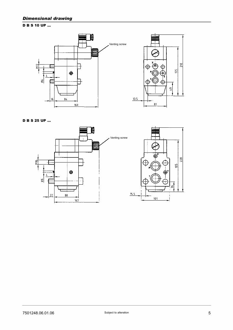
Dimensional drawing
D B S 10 UP ...
D B S 25 UP ...
Venting screw
Venting screw

6 7501248.06.01.06Subject to alteration
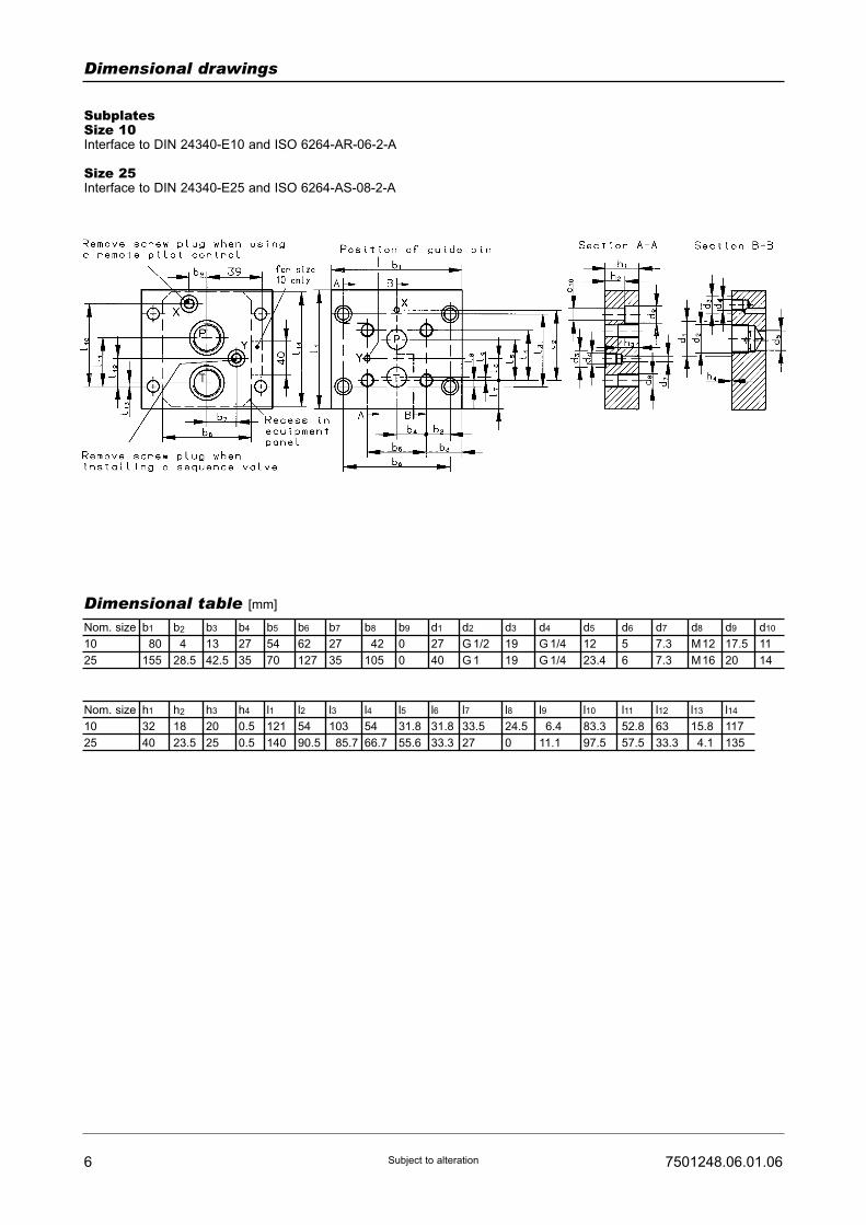
Dimensional drawings
Dimensional table [mm]
SubplatesSize 10Interface to DIN 24340-E10 and ISO 6264-AR-06-2-A
Size 25Interface to DIN 24340-E25 and ISO 6264-AS-08-2-A
Nom. size
10
25
b1
180
155
b2
14
28.5
b3
13
42.5
b4
27
35
b5
54
70
b6
62
127
b7
27
35
b8
142
105
b9
0
0
d1
27
40
d2
G 1/2
G 1
d3
19
19
d4
G 1/4
G 1/4
d5
12
23.4
d6
5
6
d7
7.3
7.3
d8
M12
M16
d9
17.5
20
d10
11
14
Nom. size
10
25
h1
32
40
h2
18
23.5
h3
20
25
h4
0.5
0.5
l1
121
140
l2
54
90.5
l3
103
185.7
l4
54
66.7
l5
31.8
55.6
l6
31.8
33.3
l7
33.5
27
l8
24.5
0
l9
16.4
11.1
l10
83.3
97.5
l11
52.8
57.5
l12
63
33.3
l13
15.8
14.1
l14
117
135

77501248.06.01.06 Subject to alteration
Spare parts drawing
Spare parts (Number of pieces)
Part
1-2
1-2
3
Spare parts
Spare parts
Connector, black
1
-
1
-
1
1
0726881
0726882
0570275
Designation Size
10
Size
25
Cat. No.
-
-
Socket-head screw(M12 x 100 DIN 912-10.9)
Socket-head screw(M16 x 110 DIN 912-10.9)
4
-
-
4
0700480
0700500
Mounting screws
1 set of spare parts consists of parts 1 and 2.
For internal control oil return via Y useM 6 x 8 DIN 912-10.9 screw,Cat. No. 0700399
For external control oil return via Y useM 6 x 18 DIN 912-10.9 screw,Cat. No. 0700403

ProportionalPressure Relief ValvesNominal sizes 10 and 25Indirectly controlledInterface to DIN 24 340 and ISO 6264
PN [pmax.] = 315 bar 7501248.06.01.06
DesignWith these proportional pressure valves, the pressure iscontrolled by means of a variable magnetic force whichacts on the piston. The indirectly controlled designconsists of the pilot stage with the proportional soleno-id, and the main stage, which is controlled by the pilotstage.The hydraulic pressure can be controlled by varying thecurrent I which is fed to the proportional solenoid; this iscarried out with the aid of a potentiometer and amplifier.
ApplicationIn hydraulic control circuits, there is often a requirementto control the pressure by means of an electrical signal,e.g. for pure remote control, in order to avoid longhydraulic lines, or for program controls where thepressure must be automatically adjusted. These propor-tional relief valves are very often fitted in process-controlled plastic moulding machines.
MountingThe units are bolted to subplates and sealed byO-rings.
Line connectionSubplate, interface to DIN 24 340 and ISO 6264.
• Simple electrical programmed control and remotecontrol
• Adjustable transient characteristics
Description (standard units)
Features
Type key
D B S ... UP G 90 ... ... O ...1 2 3 4
SubplatesProportional pressure relief valveP DB ... G ... 001 ... O O
1 2 3
1 Nominal sizes: 1025
2 Code No.: 101 - Solenoid 7289201 - Solenoid 7292
3 Engineering version: 4 - (size 25)5 - (size 10)
4 Sealing material: O - PerbunanV - Viton
1 Nominal sizes: 1025
2 Line connection: 4 - G 1/2 Size 106 - G 1 Size 25
3 Engineering version: 1
HERION Systemtechnik GmbHUntere Talstraße 65
D-71263 Weil der Stadt-Merklingen
Tel.: +49 (0) 70 33/30 18-0
Fax: +49 (0) 70 33/30 18-10
www.herion-systemtechnik.de

Type designation D B S 10 UP G... D B S 25 UP G...
General parametersDesignation Proportional pressure relief valve
Symbol simplified complete
Design Seat valve, indirectly controlled
Type mounting Flange
Line connection Subplate
Mounting position Preferably vertical (solenoid on top)
Flow direction From P to T
Actuation Proportional solenoid
Weight [kg] 7.2 9.3
Weight of subplate [kg] 2.0 4.7
Ambient temperature range ϑu [°C] –20 ... +50
Nominal size ND 10 25
Hydraulic parametersOperating pressure range pe [bar] ... 315
Adjustable pressure range pv [bar] pv min.: see characteristic curve
pv max.: 315 1)
Pressure fluid temperature ϑmmax. [°C] +70
Viscosity range ν [mm2/s] 12 ... 500
Flow Q [l/min] See characteristic curve
Control oil QST [l/min] 0.5
Hysteresis2) [%IN] <4
Repeatability2) [% pv max.] approx. ±1
Sensitivity of response2) IN [%] <1
Filtering, absolute [μm] 25
Electrical parameters proportional solenoidsSolenoid Cat. No. 7289 7292Rated current IN [mA] 800 1600
Max. input [W] 21 21
Resistance R20 [Ω] 17.6 4.6
Duty cycle [%] 100 100
Electrical connection Connector acc. to DIN 43 650 A
Degree of protection and
electric connection acc. to DIN 40 050 IP 65 IP 65
Drive electronics DC 05 / DC 05-XLT, pQ 11 and pQ 12
see table, Page 4
1) Smaller pv max. value can be set at amplifier.2) With dither: Frequency 50 Hz, amplitude 15 % IN.
2 7501248.06.01.06Subject to alteration
Parameters

37501248.06.01.06 Subject to alteration
Characteristic curves
Ordering Example of order
The units are designated by their type number. Thecomposition of this number can be drawn from the typecode. The standard versions are listed in the typesurvey. When ordering any of the standard versions,please state type number as well as catalog number topreclude possible misinterpretations.When inquiring about or ordering units not listed in ourtype survey of this publication, the type number madeup by you by means of the type code, however, will do.The corresponding catalog number will then be statedin our confirmation of order. Mounting bolts and O-ringsare included in the delivery. The subplate, amplifier anddrive electronics are to be ordered separately.
Wanted: Proportional pressure relief valve nominal size10, electrically adjustable, for flanged mounting. Settingpressure range max. 315 bar, with mating subplate.Drive electronics to be ordered separately.
Proportional pressure relief valve:Type No.: D B S 10 UP G 90 201 5 O OCat. No. 6016060.7292.01200
Subplate:Type No.: P DB 10 G 4 001 1 O OCat No.: 2852600
D B S 10 UP G 90 201 5 O O
D B S 25 UP G 90 201 4 O O
D B S 10 UP G 90 101 5 O O
D B S 25 UP G 90 101 4 O O
Valve surveyNominal
size
10
25
10
25
315
315
0 ... 1600 mA
0 ... 800 mA
DC 05, DC 05-XLT
or pQ 11 or pQ 12
see table
Page 4
DC 05, DC 05-XLT
Subplate:
Nominal size 10, G 1/2
P DB 10 G 4 001 1 OO
Cat. No. 2852600
Nominal size 25, G 1
P DB 25 G 6 001 1 OO
Cat No. 2852400
6016060.7292.
01200
6016027.7292.
01200
6016061.7289.
02400
6016062.7289.
02400
pv max.
[bar]
Proportional
solenoid current
Drive electronics Line connection Type Cat No.
Note: Valve delivered with internal control oil return via YFor units with external control oil return via X, please observe instructions given in spare parts drawings
Solenoid current [mA] Q [l/min]

4 7501248.06.01.06Subject to alteration
Drive electronicsDrive electronicsDC 05 / DC 05-XLTDigital amplifier with constant current
regulator PWM
Power supply: 18 ... 30 VDC,
incl. residual ripple
Ambient temperature ϑU: 0 ... +50 °C
Weight: 0,4 kg
Mounting position: Upright
Free air circulation must be ensured
Space requirement for installation of
19" card rack: 50 mm
European format: 100 x 160 mm
Type
For proportional directional control valvesRated current IN : 0 ... 1600 mA
7503503
7503504
Setpoint input
(switchable)
Internal
setpoints
Pcs.
Ramps
Pcs.
Terminal
strip
Form F
DIN 41612
Number
of pins
PID controller
for external
control loops
Cat. No. For Further
information,
see
script
44
4 2
48
48
51500001)
51500011)
� /�
(switchable)
�
DC 05 2 x 0...±10V
0...±10V
0(4)...20 mA
DC 05-XLT
[V] [mA]
Functional
compatible to
pQ 03
Drive electronics pQ 11Plug-in amplifier with constant current
regulator PWM
Degree of protection: IP 65
Power supply: 18 ... 32 VDC,
Residual ripple: ≤10 %
Ambient temperature ϑU: -20 ...+50 °C
Mounting position: Optional
Setpoint input
(switchable)
For proportional valves with 2 solenoids 2 pQ 11 necessaryRated current IN: 0 ... 2400 mA, allowed resistance of solenoid R20: 2,5...4,5 Ω
HERION
7502961
[mA][V]
Type of connection
Connecting
cable, 2 m
Connector acc. to
DIN 43651
Weight
[kg]
Cat. No. For Further
information,
see
script
0 ... 10
0 ... 10
0 (4)...20
0 (4)...20
�
�
�
�
5980085
59800811)
0,18
0,18
Mark in table: � without, � with1) Cable connector to be ordered separately. Cat. No. 0660689
1) Pre-parametrred electronics on request.
Drive electronics pQ 12Amplifier module with constant current
regulator PWM
Degree of protection: IP 65
Power supply: 18 ... 32 VDC,
Residual ripple: ≤10 %
Ambient temperature ϑU: -20 ...+50 °C
Mounting position: Optional
For attachment on mounting rail acc.
to EN 50022
Setpoint input
(switchable)
For proportional valves with 2 solenoids 2 pQ 11 necessary HERION
7503109
[mA] [mA][V]
Output currents Cat. No. For Furtherinformation,seescript
0 ... 10 0 (4)...20 0 ... 1600 / 2400 5980126
57501248.06.01.06 Subject to alteration
Dimensional drawing
D B S 10 UP ...
D B S 25 UP ...
Venting screw
Venting screw
6 7501248.06.01.06Subject to alteration
Dimensional drawings
Dimensional table [mm]
SubplatesSize 10Interface to DIN 24340-E10 and ISO 6264-AR-06-2-A
Size 25Interface to DIN 24340-E25 and ISO 6264-AS-08-2-A
Nom. size
10
25
b1
180
155
b2
14
28.5
b3
13
42.5
b4
27
35
b5
54
70
b6
62
127
b7
27
35
b8
142
105
b9
0
0
d1
27
40
d2
G 1/2
G 1
d3
19
19
d4
G 1/4
G 1/4
d5
12
23.4
d6
5
6
d7
7.3
7.3
d8
M12
M16
d9
17.5
20
d10
11
14
Nom. size
10
25
h1
32
40
h2
18
23.5
h3
20
25
h4
0.5
0.5
l1
121
140
l2
54
90.5
l3
103
185.7
l4
54
66.7
l5
31.8
55.6
l6
31.8
33.3
l7
33.5
27
l8
24.5
0
l9
16.4
11.1
l10
83.3
97.5
l11
52.8
57.5
l12
63
33.3
l13
15.8
14.1
l14
117
135

77501248.06.01.06 Subject to alteration
Spare parts drawing
Spare parts (Number of pieces)
Part
1-2
1-2
3
Spare parts
Spare parts
Connector, black
1
-
1
-
1
1
0726881
0726882
0570275
Designation Size
10
Size
25
Cat. No.
-
-
Socket-head screw(M12 x 100 DIN 912-10.9)
Socket-head screw(M16 x 110 DIN 912-10.9)
4
-
-
4
0700480
0700500
Mounting screws
1 set of spare parts consists of parts 1 and 2.
For internal control oil return via Y useM 6 x 8 DIN 912-10.9 screw,Cat. No. 0700399
For external control oil return via Y useM 6 x 18 DIN 912-10.9 screw,Cat. No. 0700403
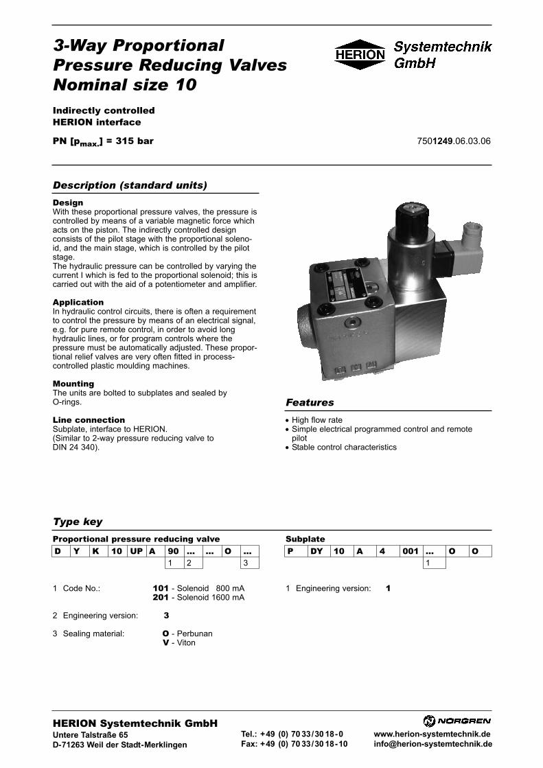
3-Way ProportionalPressure Reducing ValvesNominal size 10Indirectly controlledHERION interface
PN [pmax.] = 315 bar 7501249.06.03.06
DesignWith these proportional pressure valves, the pressure iscontrolled by means of a variable magnetic force whichacts on the piston. The indirectly controlled designconsists of the pilot stage with the proportional soleno-id, and the main stage, which is controlled by the pilotstage.The hydraulic pressure can be controlled by varying thecurrent I which is fed to the proportional solenoid; this iscarried out with the aid of a potentiometer and amplifier.
ApplicationIn hydraulic control circuits, there is often a requirementto control the pressure by means of an electrical signal,e.g. for pure remote control, in order to avoid longhydraulic lines, or for program controls where thepressure must be automatically adjusted. These propor-tional relief valves are very often fitted in process-controlled plastic moulding machines.
MountingThe units are bolted to subplates and sealed byO-rings.
Line connectionSubplate, interface to HERION.(Similar to 2-way pressure reducing valve to DIN 24 340).
• High flow rate• Simple electrical programmed control and remote
pilot• Stable control characteristics
Description (standard units)
Features
Type key
D Y K 10 UP A 90 ... ... O ...1 2 3
SubplateProportional pressure reducing valveP DY 10 A 4 001 ... O O
1
1 Code No.: 101 - Solenoid 1800 mA201 - Solenoid 1600 mA
2 Engineering version: 3
3 Sealing material: O - PerbunanV - Viton
1 Engineering version: 100
HERION Systemtechnik GmbHUntere Talstraße 65
D-71263 Weil der Stadt-Merklingen
Tel.: +49 (0) 70 33/30 18-0
Fax: +49 (0) 70 33/30 18-10
www.herion-systemtechnik.de

Type designation D Y K 10 UP A90 101 3 O O D Y K 10 UP A90 201 3 O O
General parametersDescription 3-way proportional pressure reducing valve
Symbol simplified complete
Design Piston valve, indirectly controlled
Type mounting Flange
Line connection Subplate
Mounting position free, preferably vertical (solenoid on top), to be vented at
installation via screw at solenoid actuation system
Flow direction From B to A and A to Y
Actuation Proportional solenoid
Weight pressure reducing valve [kg] 6.4
Weight of subplate [kg] 1.6
Ambient temperature ϑu [°C] –20 ... +50
Nominal size 10
Hydraulic parametersOperating pressure pe [bar] ... 315
Adjustable pressure range pv [bar] pv min.: 10 (at Q = 0 l/min)
pv max.: Pressure stage 90: Up to 315 1)
Pressure fluid temperature ϑmax. [°C] +70
Viscosity range ν [mm2/s] 12 ... 500
Flow Q [l/min] See characteristic curves
Regulating time for adjustable
pressure range from pv min. to pv max. [ms] See characteristic curve
Hysteresis2) [%IN] <4
Repeatability2) [% pv max.] approx. ±1
Sensitivity of response2) [% IN] <1
Filtering, absolute [μm] 25
Electrical parameters of proportional solenoidsSolenoid Cat. No. 7289 7292Rated current IN [mA] 800 1600
Max. input [W] 21 21
Resistance R20 [Ω] 21,3 5,7
Duty cycle [%] 100 100
Degree of protection and
electric connection acc. to DIN 40 050 IP 65 IP 65
Drive electronics DC 05 / DC 05-XLT, pQ 11 and pQ 12 see table, Page 4
1) Smaller pv max. can be set at amplifier.2) With dither: Frequency 50 Hz, amplitude 15 % IN.
2 7501249.06.03.06Subject to alteration
Parameters
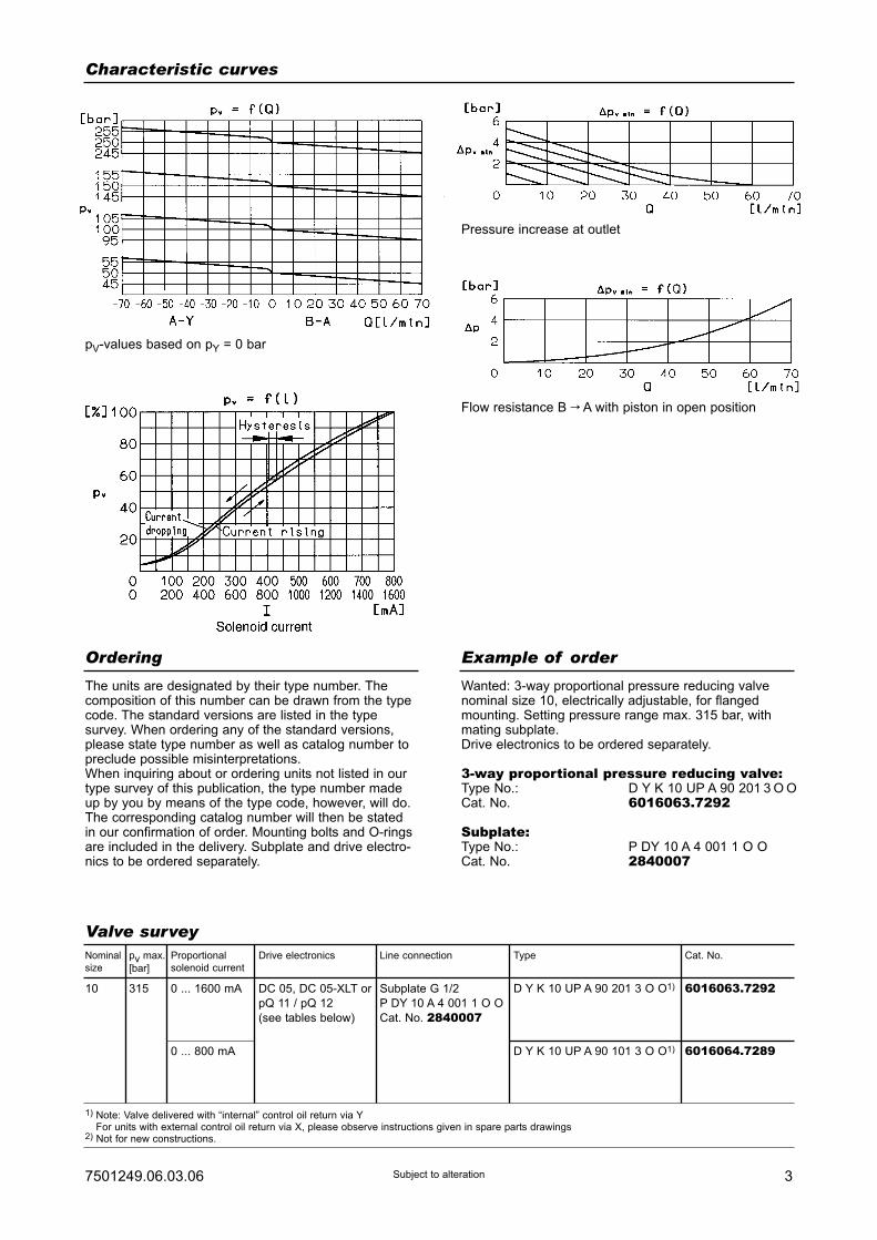
37501249.06.03.06 Subject to alteration
Characteristic curves
pV-values based on pY = 0 bar
Pressure increase at outlet
Flow resistance B C A with piston in open position
Ordering Example of order
The units are designated by their type number. Thecomposition of this number can be drawn from the typecode. The standard versions are listed in the typesurvey. When ordering any of the standard versions,please state type number as well as catalog number topreclude possible misinterpretations.When inquiring about or ordering units not listed in ourtype survey of this publication, the type number madeup by you by means of the type code, however, will do.The corresponding catalog number will then be statedin our confirmation of order. Mounting bolts and O-ringsare included in the delivery. Subplate and drive electro-nics to be ordered separately.
Wanted: 3-way proportional pressure reducing valvenominal size 10, electrically adjustable, for flangedmounting. Setting pressure range max. 315 bar, withmating subplate.Drive electronics to be ordered separately.
3-way proportional pressure reducing valve:Type No.: D Y K 10 UP A 90 201 3 O OCat. No. 6016063.7292
Subplate:Type No.: P DY 10 A 4 001 1 O OCat. No. 2840007
D Y K 10 UP A 90 201 3 O O1)
D Y K 10 UP A 90 101 3 O O1)
Valve surveyNominal
size
10 315 0 ... 1600 mA
0 ... 800 mA
DC 05, DC 05-XLT or
pQ 11 / pQ 12
(see tables below)
Subplate G 1/2
P DY 10 A 4 001 1 O O
Cat. No. 2840007
6016063.7292
6016064.7289
pv max.
[bar]
Proportional
solenoid current
Drive electronics Line connection Type Cat. No.
1) Note: Valve delivered with “internal” control oil return via YFor units with external control oil return via X, please observe instructions given in spare parts drawings
2) Not for new constructions.
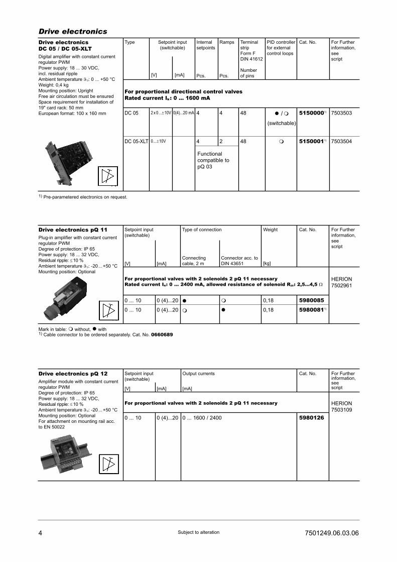
4 7501249.06.03.06Subject to alteration
Drive electronicsDrive electronicsDC 05 / DC 05-XLTDigital amplifier with constant current
regulator PWM
Power supply: 18 ... 30 VDC,
incl. residual ripple
Ambient temperature ϑU: 0 ... +50 °C
Weight: 0,4 kg
Mounting position: Upright
Free air circulation must be ensured
Space requirement for installation of
19" card rack: 50 mm
European format: 100 x 160 mm
Type
For proportional directional control valvesRated current IN : 0 ... 1600 mA
7503503
7503504
Setpoint input
(switchable)
Internal
setpoints
Pcs.
Ramps
Pcs.
Terminal
strip
Form F
DIN 41612
Number
of pins
PID controller
for external
control loops
Cat. No. For Further
information,
see
script
44
4 2
48
48
51500001)
51500011)
� /�
(switchable)
�
DC 05 2 x 0...±10V
0...±10V
0(4)...20 mA
DC 05-XLT
[V] [mA]
Functional
compatible to
pQ 03
Drive electronics pQ 11Plug-in amplifier with constant current
regulator PWM
Degree of protection: IP 65
Power supply: 18 ... 32 VDC,
Residual ripple: ≤10 %
Ambient temperature ϑU: -20 ...+50 °C
Mounting position: Optional
Setpoint input
(switchable)
For proportional valves with 2 solenoids 2 pQ 11 necessaryRated current IN: 0 ... 2400 mA, allowed resistance of solenoid R20: 2,5...4,5 Ω
HERION
7502961
[mA][V]
Type of connection
Connecting
cable, 2 m
Connector acc. to
DIN 43651
Weight
[kg]
Cat. No. For Further
information,
see
script
0 ... 10
0 ... 10
0 (4)...20
0 (4)...20
�
�
�
�
5980085
59800811)
0,18
0,18
Mark in table: � without, � with1) Cable connector to be ordered separately. Cat. No. 0660689
1) Pre-parametered electronics on request.
Drive electronics pQ 12Amplifier module with constant current
regulator PWM
Degree of protection: IP 65
Power supply: 18 ... 32 VDC,
Residual ripple: ≤10 %
Ambient temperature ϑU: -20 ...+50 °C
Mounting position: Optional
For attachment on mounting rail acc.
to EN 50022
Setpoint input
(switchable)
For proportional valves with 2 solenoids 2 pQ 11 necessary HERION
7503109
[mA] [mA][V]
Output currents Cat. No. For Furtherinformation,seescript
0 ... 10 0 (4)...20 0 ... 1600 / 2400 5980126
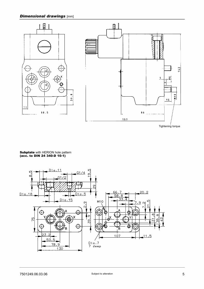
57501249.06.03.06 Subject to alteration
Dimensional drawings [mm]
Subplate with HERION hole pattern(acc. to DIN 24 340-D 10-1)
Tightening torque

6 7501249.06.03.06Subject to alteration
Spare parts drawing
Part
1
2
3
1
O-ring (17.1 x 2.6)
O-ring (9.2 x 1.8)
07012900701252
Qty. Description Cat. No.
Spare parts
- 4 Socket-head screw
(M10 x 90 DIN 912-10.9)
0700462Mountings screws
1 set of spare parts consists of parts 1 and 2.
Venting screw
For “external” control oil
return via “X” closed with
screw M 6 x 8 DIN 913
Cat. No. 0700514

Directional control valvesDN 6 (NG 6)Directly actuatedInterface to DIN 24 340 and ISO 4401
PN [pmax.] = 315 bar
7501292.06.03.05
DesignThe design is based upon the 5-chamber system.A spool of hardened steel slides in a housing made ofhigh-strength cast-iron. Therefore the units are suitablefor rough operating conditions.
ActuationThe directional control valves can be actuated eitherelectromagnetically, electropneumatically, hydraulically,pneumatically, mechanically or by spring.
MountingThe units are bolted on subplates and sealed byO-rings.
Line connectionSubplate, interface to DIN 24340-A6 and ISO 4401-AB-03-4-A.
Description (standard units)
Type key
S 6 ... ... G ... 001 ... ... ...1 2 3 4 5 6
Directional control valve
1 Actuation: VH – DC-type solenoid, pressure-tight, with manual override
V – Without manual override
2 Electrical 10 – Connector Pg 11connection: to DIN 43650 on solenoid
11 – Connector Pg 11with rectifier insert on solenoid
12 – Connector Pg 11with rectifier insert and functionindicator on solenoid
13 – Connector Pg 11with function indicator onsolenoid
4 Engineering version: 6 – Wet solenoid provided withcentral thread
5 Additional data: O – Standard design
M1) – Mechanical detent
C2) – Switching delay by means ofnozzle
6 Sealing material: V – FKM (e.g. Viton)
1)2-position valves available with detent for all types of actutor, except roller tappet
(R). 3-position valve can only be arrested by means of a hand lever.2)
Port T of valves with a delayed switching time, must be pressurized with approx.
5 bar.3)
Port T of these 3/2 directional control valves is used as leak oil connection.
• Good guidance of the spool (5-chamber system)- this means reliable switching even with long restperiod
• No dynamic seals• Delay of switching time by exchangeable nozzle• Solenoids with pressure-tight core tube (tube secured)
to valve body by means of central thread). No need toopen pressure-tight space when replacing coil
• Valves with Viton seals standard• Coils designed for DC voltage. AC operation via
connector equipped with rectifier
Features
HERION Systemtechnik GmbHUntere Talstraße 65
D-71263 Weil der Stadt (Merklingen)
Tel.: +49 (0) 70 33/30 18-0
Fax: +49 (0) 70 33/30 18-10
www.herion-systemtechnik.de
3 Symbol
Symbol SymbolNo.
Overlap Symbol SymbolNo.
Overlap
0013)
003
020
004
005
0443)
039
0213)
019
025
+
-
+
+
+
+
+
+
+
+
0313)
038
035
002
008
009
010
011
013
016
+
+
+
-
+
+
+
-
-
+

Type designation VH 10 VH 11
General parametersDesignation Directional control valve
Symbol See type survey or type key
Design Spool-type valve
Type of mounting Flange
Line connection Subplate
Mounting position Preferably horizontal
Weight of valve with 1 actuator [kg] 1.9
2 actuators 2.7
Weight of G 1/4 [kg] 0.7
subplate G 3/8 1
Ambient temperature range ϑu [°C] -20 to +50
Size DN 6
Hydraulic parametersOperating pressure pe max. [bar]
at port P, A, B up to 315
at port T up to 160
Pressure fluid temperature ϑm max. [°C] +70
Viscosity range ν [mm2/s] 12 to 500
Flow Qmax. [l/min] See characteristic curves
Filtration Oil purity class to ISO 4406: 18/15
Further parametersManual override Standard
Switching times, approx. [ms]
ton 50 to 80
toff 30 to 55
Number of switchings/h, approx. 15000
Rated voltage UN [V] Standard voltages
Connector input 24 VDC 230 VAC / 40 ... 60 HZ
±10% +5%/-10%
Further voltages on request
Power consumption P20 [W] 31
Duty cycle EDrel [%] 100
Degree of protection for solenoid and
electrical connection to DIN 40050 IP 65
2 7501292.06.03.05Subject to alteration
Parameter to VDI 3267
SubplateP S 6 G ... ... ... O O
1 2 3
1 Line connection: 200 - G 1/4 (internal thread300 - G 3/8 to DIN ISO 228/1)
2 Code: 024 - G 1/4001 - G 3/8
3 Engineering version: 200
Type key

37501292.06.03.05 Subject to alteration
Characteristic curvesFlow curves ?p = f(Q)
Symbol
001
003
008
009
013
019
020
7
8
8
5
5
5
5
7
8
8
5
5
5
5
-
3
6
9
4
1
1
-
3
6
9
4
1
1
-
-
-
-
2
-
-
Flow direction
P-A P-B A-T B-T P-T
Symbol Characteristic curve
001
003
008
009
013
019
020
2
4
1
3
5
1
1
Maximum values determined with solenoid in warmed-up condition and at an undervoltage of 10%. Fluidpassing in two directions (from P to A and B to T). Ifone port is closed, a reduced breaking capacity must betaken into consideration. Further valves with differentswitching symbols available on request.
Ordering Example of orderThe units are designated by their type number. Thecomposition of this number can be drawn from the typecode. The standard versions are listed in the typesurvey. When ordering any of the standard versions,please state type number as well as catalog number topreclude possible misinterpretations.Further valve versions can be composed via combi-nation of types. The catalog number of these devicesyou will get on request.Flanges valves are provided with O-rings and connector(type 10 or 11, Page 2). Subplate and mounting screwsmust be ordered separately.
Wanted: 4/3 directional control valve DN 6, 24 VDC,connector on solenoid, Symbol 008, along withcorresponding subplate.
Directional control valve:Type No.: S 6 VH 10 G 008 001 6 O VCat. No.: 5203943.7234
Subplate:Type No.: P S 6 G 2 024 2 O OCat. No.: 1065173
Mounting screws: (4 pcs. required)Socket-head screw: (M 5 x 30 DIN 912-10.9)Cat. No.: 0700387
LeistungsgrenzenPower limits
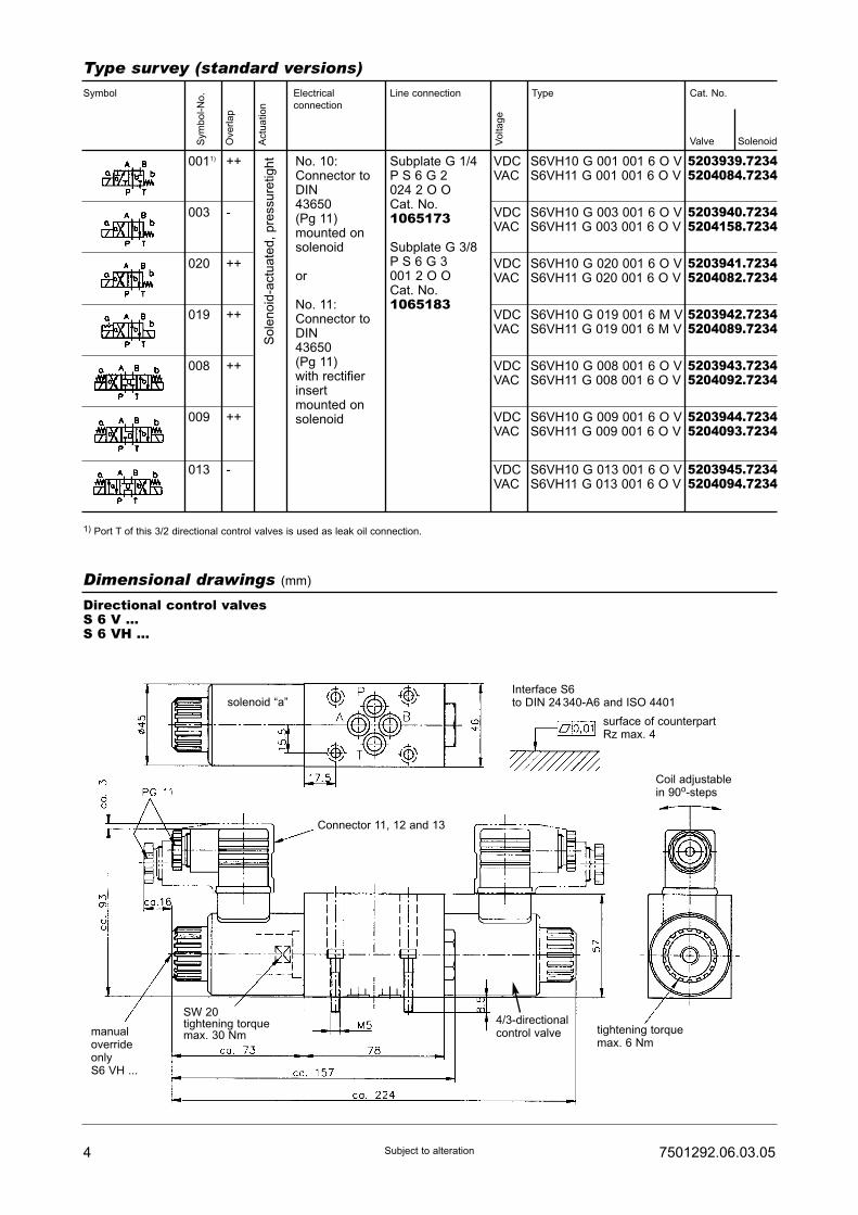
4 7501292.06.03.05Subject to alteration
Type survey (standard versions)
1) Port T of this 3/2 directional control valves is used as leak oil connection.
Sym
bo
l-N
o.
Ove
rla
p
Actu
atio
n
Vo
lta
ge
Symbol Electrical
connection
Line connection Type Cat. No.
Valve Solenoid
0011)
003
020
019
008
009
013
++
-
++
++
++
++
-
VDCVAC
VDCVAC
VDCVAC
VDCVAC
VDCVAC
VDCVAC
VDCVAC
S6VH10 G 001 001 6 O VS6VH11 G 001 001 6 O V
S6VH10 G 003 001 6 O VS6VH11 G 003 001 6 O V
S6VH10 G 020 001 6 O VS6VH11 G 020 001 6 O V
S6VH10 G 019 001 6 M VS6VH11 G 019 001 6 M V
S6VH10 G 008 001 6 O VS6VH11 G 008 001 6 O V
S6VH10 G 009 001 6 O VS6VH11 G 009 001 6 O V
S6VH10 G 013 001 6 O VS6VH11 G 013 001 6 O V
5203939.72345204084.7234
5203940.72345204158.7234
5203941.72345204082.7234
5203942.72345204089.7234
5203943.72345204092.7234
5203944.72345204093.7234
5203945.72345204094.7234
So
len
oid
-actu
ate
d,
pre
ssu
retig
ht No. 10:
Connector toDIN43650(Pg 11)mounted onsolenoid
or
No. 11:Connector toDIN43650(Pg 11)with rectifierinsertmounted onsolenoid
Subplate G 1/4P S 6 G 2024 2 O OCat. No.1065173
Subplate G 3/8P S 6 G 3001 2 O OCat. No.1065183
Dimensional drawings (mm)
Directional control valvesS 6 V ...S 6 VH ...
solenoid “a”Interface S6to DIN 24340-A6 and ISO 4401
surface of counterpartRz max. 4
Connector 11, 12 and 13
tightening torquemax. 6 Nm
SW 20tightening torquemax. 30 Nmmanual
overrideonlyS6 VH ...
4/3-directionalcontrol valve
Coil adjustablein 90o-steps

57501292.06.03.05 Subject to alteration
Dimensional drawings (mm)
Directional control valves
S 6 V ... M ...S 6 VH ... M ...
Subplates with interface according to DIN 24 340-A 6 and ISO 4401-AB-03-4-A
G 1/4
G 3/8
solenoid “a” solenoid “b”
Aperture for
connection in
control panel
Aperture for
connection in
control panel

6 7501292.06.03.05Subject to alteration
Spare parts drawing
S 6 V ...S 6 VH ...
S 6 V ... MS 6 VH ... M
with mechanicaldetent
S 6 V ... C ...S 6 VH ... C ...
Switching time delay withnozzle
Spare parts (pieces)
Part
1 O-ring (9.2 x 1.8) 4 4
2 O-ring (17 x 2)
O-ring (26.7 x 1.78)
O-ring (22 x 1.5)
Sealing ring (U 5.7 x 9 x 1)
Nozzle M 5 x 6 (0.5 mm)
DC solenoid(state voltage!)
2 0615057 2
3
4
6
7
5
2
2
-
-
1 or 2
2
2
1
-
4
2
2
2
1
1
1 or 21 or 27234
0615760
7234
0615381
7234
S 6 VH 10 ...
S 6 VH 11 ...
pcs spare part kit pcs spare part kit pcs spare part kit
S 6 VH 10 ... M ...
S 6 VH 11 ... M ...
S 6 VH 10 ... C ...
S 6 VH 11 ... C ...
Designation
vent screw
4/3 - Directional Valve

77501292.06.03.05 Subject to alteration
Electrical spare partsElectrical connection, Symbol 10 Cat. No.
Connector:
Design A (grey) 0657859
Design B (black) 0570275
Electrical connection, Symbol 11 Cat. No.
Connector withrectifier insert230V/50Hz
Design A (grey) 0570322
Design B (black) 0570819
Electrical connection, Symbol 12 Cat. No.
Connector withrectifier insert230V/50Hzand function indicator
Design A (grey) 0571501
Design B (black) 0571502
Electrical connection, Symbol 13 Cat. No.
Connector withfunction indicator
Design A (grey) 0570256
Design B (black) 0570818
CommissioningTurn out vent screw and fill in foam-free oil while valvesis in neutral position. It is not necessary to remove theunit which may remain in pressurized condition.Pressurize Port P with approx. 5 br. Screw in ventscrew (approx. 2 to 3 turns) and switch valve approx.10 times. Turn out vent screw again and refill oil (withvalve remaining in neutral position). Tighten vent screwwhen air bubbles are no longer visible.To ensure a proper function, the pressure space of thesolenoid must be deaerated and filled with oil.

8 7501292.06.03.05Subject to alteration
Notes:

3 Symbol
4 Engineeringversion: 6
5 Additional data: O – Standard designM – Mechanical detent 1)
6 Sealing material: V – Viton
Directional Control ValvesSize 6
direct controlledPort size G 3/8
PN [pmax.] = 315 bar 7501293.06.02.06
DesignThe design is based upon the 5-chamber-system.A spool of hardened steel slides in a housing made ofhigh-strength cast-iron. The units are therefore suitablefor rough operating conditions.
ActuationThe directional control valves can be actuated eitherelectromagnetically, electropneumatically, hydraulically,pneumatically, mechanically or by spring.
MountingBy means of bolts onto equipment rack, etc., or to pipeline.
Line connectionPort size G 3/8.
Description (standard units)
• Good guidance of the spool (5-chamber system)- this means reliable switching even with long restperiod
• No dynamic seals• Delay of switching time by exchangeable nozzle• Solenoids with pressure-tight core tube (tube secured)
to valve body by means of central thread). No need toopen pressure-tight space when replacing coil
• Valves with Viton seals standard• Coils designed for DC voltage. AC operation via
connector equipped with rectifier• No dynamic seals
Features
HERION Systemtechnik GmbHUntere Talstraße 65
D-71263 Weil der Stadt-Merklingen
Tel.: +49 (0) 70 33/30 18-0
Fax: +49 (0) 70 33/30 18-10
www.herion-systemtechnik.de
1 Actuation: VH – DC solenoid, pressure-tightwith manual override
Other actuations e.g. pneumatical hydraulical by rollerlever or by hand on request.
2 Electricalconnection: 00 – Actuation without
electrical connection
10 – Plug socket Pg 11to DIN 43650 on solenoid
11 – Plug socket Pg 11to DIN 43650 on solenoidand incorporated rectifier
13 – Plug socket Pg 11to DIN 43650 on solenoid,plug socket provided withsignal indicator
Symbol Symbol
No.
001 3)
020
019 2)
+
+
+
008
009
013
+
+
-
Over-
lap
Symbol Symbol
No.
Over-
lap
Type code
S 6 ... ... S 3 ... 001 ... ... ...1 2 3 4 5 6
Directional control valve
1)on request
2)2-position valves available with detent for all types of actutor, except roller tappet
(R). 3-position valve can only be arrested by means of a hand lever.3)
Port T of these 3/2 directional control valves is used as leak oil connection.

Other parametersManual override yes
Switching times appr. [ms]
te 50 ... 80
ta 30 ... 55
Approx. number of switchings/h 15 000
Rated voltage UN [V] Standard voltages
(other voltages 24 ± 10 % 230 V/50 Hz
available on request) + 5 / - 10 %
Current draw P20 [W] DC 31
Duty cycle EDrel [%] 100
Degree of protection for solenoid IP 65
and electrical connection to DIN 40 050
Hydraulic parametersOperating pressure range pe max. [bar]
at port P, A, B ... 315
at port T ... 160
Pressure fluid temperature ϑm max. [°C] + 70
Viscosity range ν [mm2/s] 12 ... 500
Flow Qmax (l/min) See characteristic curve
Filtering Oil class according to
ISO 4406: 18/15
2 7501293.06.02.06Subject to alteration
Type designation (Actuation) VH 10 ... VH 11 ...
General parametersDesignation Directional control valve
Symbol See type survey and type code
Design Spool-type valve
Type of mounting Flange
Line connection Port size
Mounting position Preferably horizontal
Weight 1 actuator [kg] 1.9 1.9
2 actuators 2.7 2.7
Ambient temperature range ϑu [°C] – 20 ... + 50
Size NG 6
Parameters according to VDI 3267
Symbol Characteristic curve
001
008
009
013
019
020
1
3
2
3
3
3
Flow QmaxLimiting values measured with warmsolenoid and 10% low voltage. Valvepassed though in both directions (P-Aand B-T). Blocking of one port lead tolower switching capacities.
Symbol
001
008
009
013
019
020
5
6
5
3
7
7
5
6
5
3
7
7
-
3
4
1
2
2
-
3
4
1
2
2
-
-
-
8
-
-
Flow direction
P-A P-B A-T B-T P-T
Flow resistance

37501293.06.02.06 Subject to alteration
Ordering Example of order
The units are designated by their type number. Thecomposition of this number can be drawn from the typecode. The standard versions are listed in the typesurvey. When ordering any of the standard versions,please state type number as well as catalog number topreclude possible misinterpretations.When inquiring about or ordering units not listed in ourtype survey of this publication, the type number madeup by you by means of the type code, however, will do.The corresponding catalog number will then be statedin our confirmation of order.
Wanted: 4/3-way directional control valve NG 6, 24 VDC. Electrical connection: Plug socket on solenoid,Symbol 008, port size G 3/8.
Directional control valve:Type No.: S 6 VH 10 S3 008 001 6 O VCat. No.: 5201449.7234
Type survey (standard versions)
Sym
bo
l N
o.
Ove
rla
p
Actu
atio
n
Dim
en
sio
na
ld
raw
ing
Spa
re p
art
dra
win
g
Vo
lta
ge
Symbol Electrical
connection
Line connection Type Cat. No.
Valve
Sole-
noid
0011) 01
01
03
02
02
02
01
01
03
02
02
02
020
019
008
009
013
+
+
+
+
+
-
VDC
VAC
VDC
VAC
VDC
VAC
S 6 VH 10 S3 001 001 6 O V
S 6 VH 11 S3 001 001 6 O V
S 6 VH 10 S3 020 001 6 O V
S 6 VH 11 S3 020 001 6 O V
S 6 VH 10 S3 019 001 6 M V
S 6 VH 11 S3 019 001 6 M V
5201501.72345201506.7234
5204087.72345204088.7234
5201504.72345201508.7234
VDC
VAC
S 6 VH 10 S3 008 001 6 O V
S 6 VH 11 S3 008 001 6 O V
5201449.72345201509.7234
VDC
VAC
S 6 VH 10 S3 009 001 6 O V
S 6 VH 11 S3 009 001 6 O V
5201502.72345201510.7234
VDC
VAC
S 6 VH 10 S3 013 001 6 O V
S 6 VH 11 S3 013 001 6 O V
5201503.72345202029.7234
Sole
noid
actu
ate
d p
ressure
tig
ht No. 10:
Plug socket
to DIN
43650
(Pg 11)
on solenoid
or
No. 11:
Plug socket
to DIN
43650
(Pg 11) on
solenoid
with
incorporated
rectifier
G 3/8
1)Port T of these 3/2 directional control valves is used as leak oil connection.
Dimensional drawings
S 6 VH 10S 6 VH 11 01
S 6 VH 10S 6 VH 11 02
S 6 VH 10 ... MS 6 VH 11 ... M 03
El. connection 11 and 13
El. connection 10
Port,
A, P, B and T
appr. 157
appr. 102
appr. 73
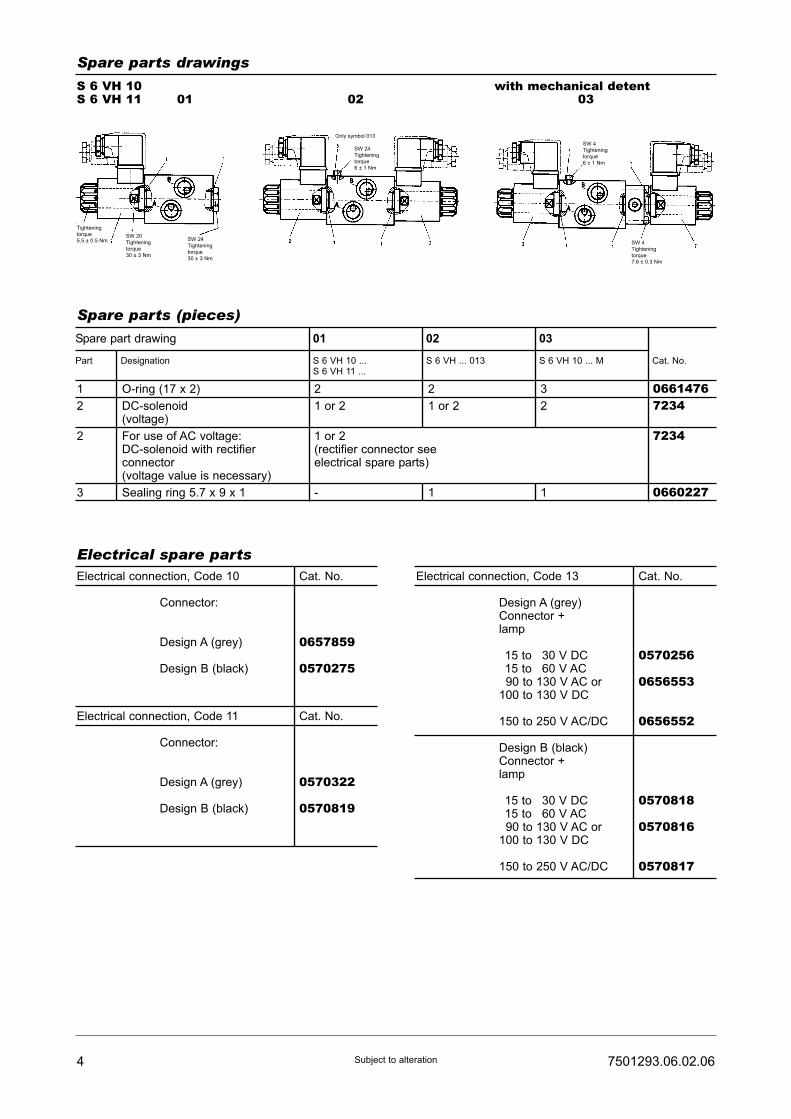
4 7501293.06.02.06Subject to alteration
Spare parts drawings
S 6 VH 10S 6 VH 11 01 02
with mechanical detent03
Spare parts (pieces)
Spare part drawing 01 02 03
Part Designation S 6 VH 10 ... S 6 VH ... 013 S 6 VH 10 ... M Cat. No.S 6 VH 11 ...
Electrical spare partsElectrical connection, Code 10 Cat. No.
Connector:
Design A (grey) 0657859
Design B (black) 0570275
Electrical connection, Code 11 Cat. No.
Connector:
Design A (grey) 0570322
Design B (black) 0570819
Electrical connection, Code 13 Cat. No.
Design A (grey)Connector +lamp
115 to 130 V DC 0570256115 to 160 V AC190 to 130 V AC or 0656553100 to 130 V DC
150 to 250 V AC/DC 0656552
Design B (black)Connector +lamp
115 to 130 V DC 0570818115 to 160 V AC190 to 130 V AC or 0570816100 to 130 V DC
150 to 250 V AC/DC 0570817
1
2
2
3
2
1 or 2
1 or 2(rectifier connector seeelectrical spare parts)
-
2
1 or 2
1
3
2
1
06614767234
7234
0660227
O-ring (17 x 2)
DC-solenoid(voltage)
For use of AC voltage:DC-solenoid with rectifierconnector(voltage value is necessary)
Sealing ring 5.7 x 9 x 1
Tightening
torque
5.5 ± 0.5 NmSW 20
Tightening
torque
30 ± 3 Nm
SW 24
Tightening
torque
30 ± 3 Nm
Only symbol 013
SW 24
Tightening
torque
6 ± 1 Nm
SW 4
Tightening
torque
6 ± 1 Nm
SW 4
Tightening
torque
7.6 ± 0.3 Nm

Directional control valvesSize 6direct controlledwith inductive switching position monitoringinductive limit swithInterface to DIN 24 340 and ISO 4401
PN [pmax.] = 315 bar 7501294.06.03.05
DesignThese directional control valves are based on the 5-chamber system, and are designed in the form ofspool valves. A spool of hardened steel slides in anhousing made of high-strength cast iron. The units aretherefore suitable for rough operating conditions.The switch contact at the end positions of the spool canbe used, for example, for acknowledgements in safetycircuits. When the ed switching position is reached, apin which is rigidly connected to the steel spool entersthe electrical field created by the electronic limit switch.The signal thus produced represents an acknowledge-ment from the spool.
ActuationThe directional control vlaves are actuated electro-mag-netically and by means of a spring.
MountingThe units are bolted on subplates and sealed byO-rings.
Line connectionSubplate, hole pattern to DIN 24340 - A6 andISO 4401 - AB - 03 - 4 - A.
Description (standard units)
Type code
S 6 ... ... G ... ... ... ... ...1 2 3 4 5 6 7
Directional control valve
1 Actuation: VH – DC solenoid, pressuretightwith manual override
V – DC solenoid, pressuretightwithout manual override
2 Electrical 10 – Connector Pg 11connection: to DIN 43650 on solenoid
11 – Connector Pg 11with rectifier insert on solenoid
13 – Connector Pg 11with function indicator onsolenoid
3 Symbol: 001 – See type survey
4 Code: 210 – limit switch on side bposition a monitored
2161) – 2 limit switches on sidesa and bposition a and b monitored
4 Code: 217 – limit switch on side bspring returnedposition a or b monitored
220 – limit switch on side bposition b monitored
222 – limit switch on side amechanical detentposition a monitored
223 – limit switch on side amechanical detentposition b monitored
5 Engineering version: 6 – Wet solenoid provided withcentral thread
6 Additional data: O – Standard design
M – Mechanical detent
7 Sealing material: V – FKM (e.g. Viton)
• Good guidance of the spool - this means reliableswitching, even with long rest periods
• Axial forces acting on the spool are reduced by anamount equal to the pulse forces encountered in the3-chamber system and caused by theuncompensated ring surfaces in this system
• Increased degree of safety, thanks to the electricalswitching positions monitoring
Features
HERION Systemtechnik GmbHUntere Talstraße 65
D-71263 Weil der Stadt-Merklingen
Tel.: +49 (0) 70 33/30 18-0
Fax: +49 (0) 70 33/30 18-10
www.herion-systemtechnik.de

Type designation S 6 V 10 G ... S 6 VH 10 G ... S 6 VH 11 G ...
General parametersDesignation Directional control valve
Symbol See type survey
Design Spool-type valve
Type of mounting Flange
Line connection Subplate
Mounting position Preferably horizontal
Weight [kg]
1 actuator 2,1
2 actuators 3,1
Weight of subplate [kg]
G 1/4 0,7
G 3/8 1
Ambient temperature range ϑu [°C] -20 ... +50
Size NG 6
Hydraulic parametersOperating pressure range pe [bar]
at port P, A, B ... 315
at port T ... 50
Pressure fluid temperature ϑm max. [°C] +70
Viscosity range ν [mm2/s] 12 ... 500
Flow Qmax. [l/min] See characteristic curve
Filtration Oil purity class to ISO 4406: 18/15
Other parametersManual override no yes
Switching times t approx. [ms]
ton 50 ... 80
toff 30 ... 55
Approx. number of switchings/h 15000
Rated voltage UN [V] DC 24 ±10% AC 230 V 50 HZ
+5%-10%
Other voltages available on request
Power consumption PN20 [W] 31
Duty cycle EDrel [%] 100
Degree of protection for solenoid and
electrical connection to DIN 40050 IP 65
2 7501294.06.03.05Subject to alteration
Parameters
SubplateP S 6 G ... ... ... O O
1 2 3
1 Line connection: 200 - G 1/4 (Internal thread300 - G 3/8 to DIN ISO 228/1)
2 Code: 024 - G 1/4001 - G 3/8
3 Engineering version: 200
Type code

Electrical parameters (electronic limit switch)Connector type angle, female, 4-pin
Cable gland Pg 7, cable ø 4 to 6 mm
Degree of protection IP 67
Indicator LED yes (2)
- Power on green
- Function yellow
Pin assignmentconnector
37501294.06.03.05 Subject to alteration
Type designation S 6 V 10 G ... S 6 VH 10 G ... S 6 VH 11 G ...
Electrical parameters (electronic limit switch)Electronical limit switch M 12 x 1 PNP output/active area green/loose cable end
Rated operational voltage Ue [V] DC 24
Supply voltage UB [V] DC 10 ... 30
Voltage drop Ud at Ie [V] ≤1,5
Rated operational current Ie [mA] 200
Protection against polarity reversal yes
Short circuit protected/overload protected yes / yes
Load capacitance [μF] ≤1,0
Degree of protection per IEC 529 IP 68 to BWN Pr. 20 (IP 67 connector kompl.)
Connection Connector
pressure rated up to [bar] 50
Electrical parameters (electronic limit switch)
Wiring diagram Pin assignmentlimit switch
Parameters
brown
black
blue
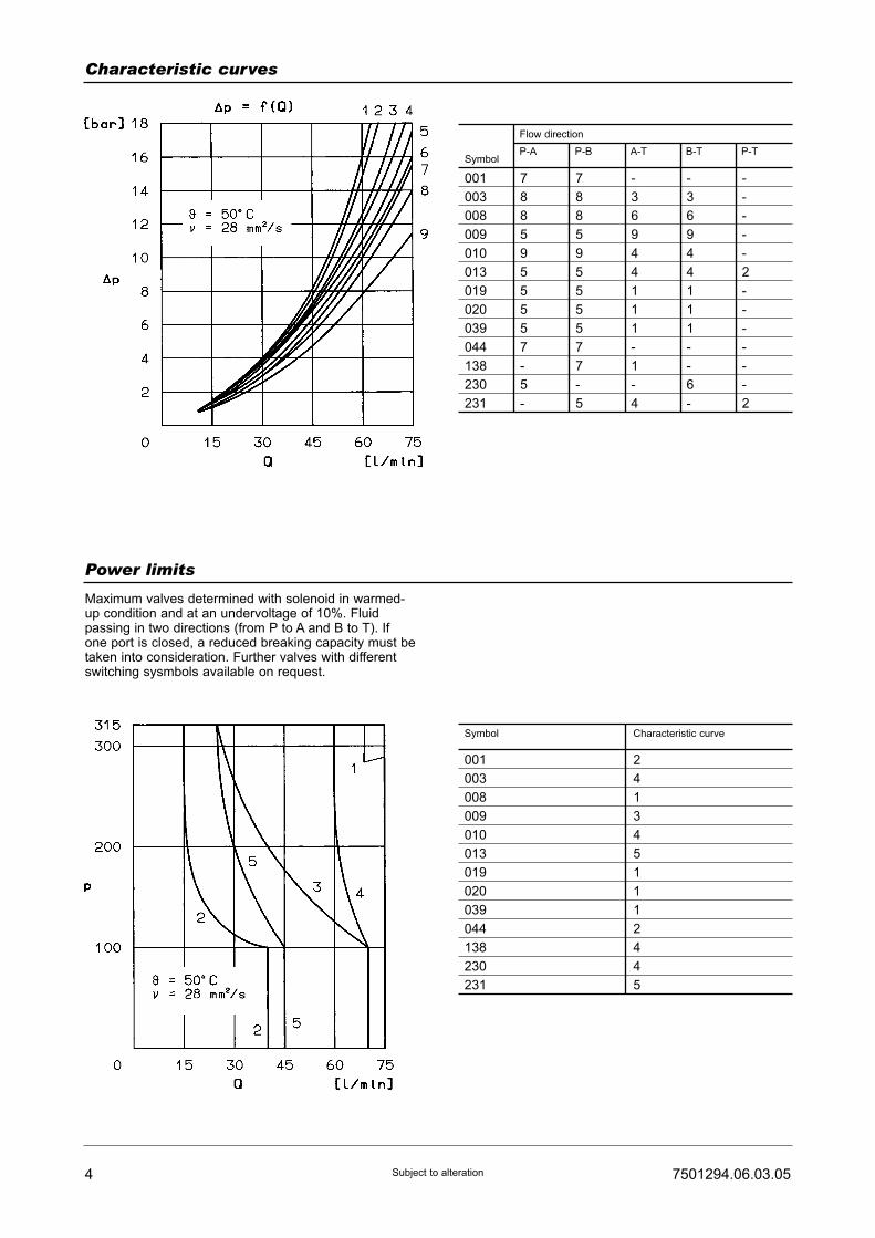
4 7501294.06.03.05Subject to alteration
Characteristic curves
Power limits
Symbol
001
003
008
009
010
013
019
020
039
044
138
230
231
7
8
8
5
9
5
5
5
5
7
-
5
-
7
8
8
5
9
5
5
5
5
7
7
-
5
-
3
6
9
4
4
1
1
1
-
1
-
4
-
3
6
9
4
4
1
1
1
-
-
6
-
-
-
-
-
-
2
-
-
-
-
-
-
2
Flow direction
P-A P-B A-T B-T P-T
Symbol Characteristic curve
001
003
008
009
010
013
019
020
039
044
138
230
231
2
4
1
3
4
5
1
1
1
2
4
4
5
Maximum valves determined with solenoid in warmed-up condition and at an undervoltage of 10%. Fluidpassing in two directions (from P to A and B to T). Ifone port is closed, a reduced breaking capacity must betaken into consideration. Further valves with differentswitching sysmbols available on request.

57501294.06.03.05 Subject to alteration
Type survey (standard versions)
1) For other symbols, see Publication 7501292.2) The T-port of the valve is used for leakage drain.
Lä
ufe
r-N
r.
Sym
bo
l-N
o.
Ove
rla
p
Actu
atio
n
Vo
lta
ge
Symbol 1) Electrical
connec-
tion
Line
connection
Type Cat-No.
Valve Solenoid
210 0012)
020
039
138
008
020
011
013
020
0442)
138
230
231
008
019
019
+
+
+
+
+
+
-
-
+
+
+
-
-
+
+
+
VDC
VDC
VDC
VDC
VDC
VDC
VDC
VDC
VDC
VDC
VDC
VDC
VDC
VDC
VDC
VDC
S6VH10 G 001 210 6 O V
S6VH10 G 020 210 6 O V
S6VH10 G 039 210 6 O V
S6V10 G 138 210 6 O V
S6VH10 G 008 216 6 O V
S6VH10 G 020 216 6 O V
S6VH13 G 011 216 6 O V
S6VH10 G 013 216 6 O V
S6VH11 G 020 217 6 O V
S6V10 G 044 217 6 O V
S6V10 G 138 217 6 O V
S6VH10 G 230 217 6 O V
S6VH10 G 231 217 6 O V
S6V10 G 008 220 6 O V
S6VH10 G 019 222 6 M V
S6VH10 G 019 223 6 M V
5205076.7234
5205042.7234
5205160.7234
5205151.7238
5205196.7234
5205046.7234
5205106.7234
5205098.7234
5205122.7234
VDC S6VH10 G 020 217 6 O V 5205045.7234
5205095.7238
5205096.7238
5205157.7234
5205158.7234
5205099.7238
5205129.7234
5205208.7234
216
217
220
222
223
So
len
oid
-actu
ate
d,
pre
ssu
retig
ht No. 10:
Connector to DIN43650(Pg 11)mountedon sole-noid
No. 11:Connector to DIN43650(Pg 11)withrectifierinsertmountedon sole-noid
No. 13:Connector to DIN43650(Pg 11)withfunctionindicatormountedon sole-noid
SubplateG 1/4P S 6 G 2024 2 O OCat. No.1065173
SubplateG 3/8P S 6 G 3001 2 O OCat. No.1065183
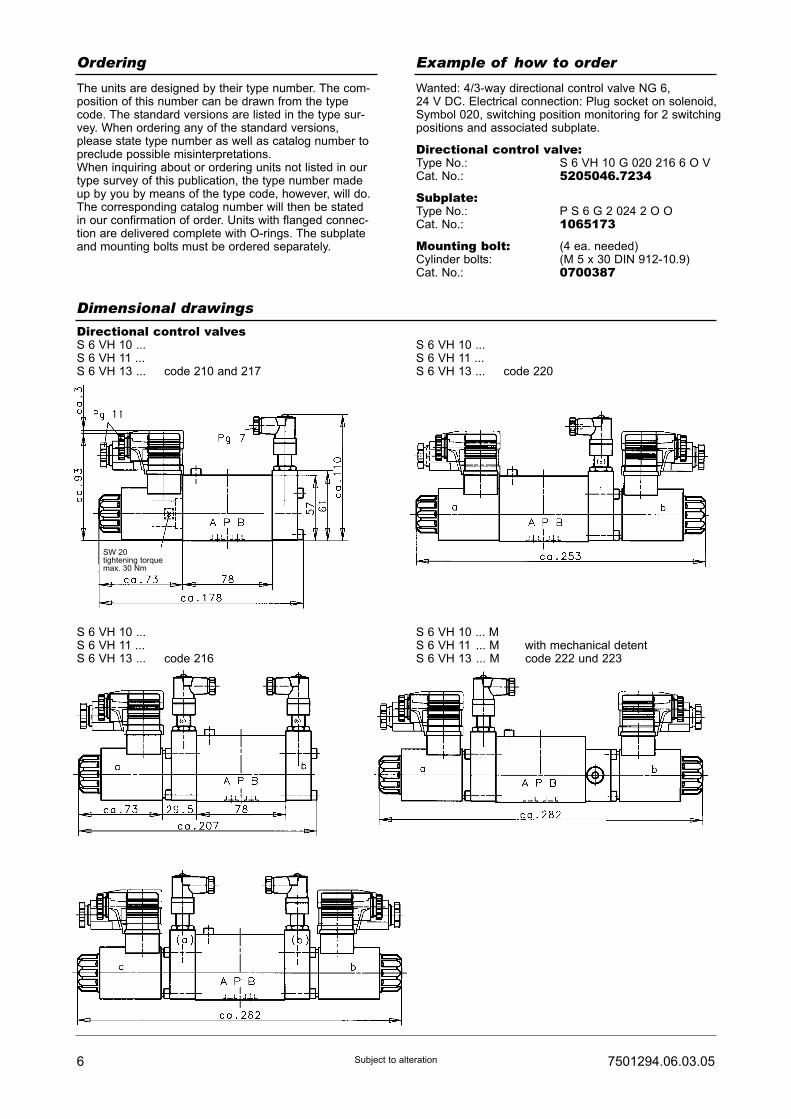
6 7501294.06.03.05Subject to alteration
Dimensional drawings
Directional control valvesS 6 VH 10 ...S 6 VH 11 ...S 6 VH 13 ... code 210 and 217
S 6 VH 10 ...S 6 VH 11 ...S 6 VH 13 ... code 220
S 6 VH 10 ...S 6 VH 11 ...S 6 VH 13 ... code 216
S 6 VH 10 ... MS 6 VH 11 ... M with mechanical detentS 6 VH 13 ... M code 222 und 223
Ordering Example of how to order
The units are designed by their type number. The com-position of this number can be drawn from the typecode. The standard versions are listed in the type sur-vey. When ordering any of the standard versions,please state type number as well as catalog number topreclude possible misinterpretations.When inquiring about or ordering units not listed in ourtype survey of this publication, the type number madeup by you by means of the type code, however, will do.The corresponding catalog number will then be statedin our confirmation of order. Units with flanged connec-tion are delivered complete with O-rings. The subplateand mounting bolts must be ordered separately.
Wanted: 4/3-way directional control valve NG 6,24 V DC. Electrical connection: Plug socket on solenoid,Symbol 020, switching position monitoring for 2 switchingpositions and associated subplate.
Directional control valve:Type No.: S 6 VH 10 G 020 216 6 O VCat. No.: 5205046.7234
Subplate:Type No.: P S 6 G 2 024 2 O OCat. No.: 1065173
Mounting bolt: (4 ea. needed)Cylinder bolts: (M 5 x 30 DIN 912-10.9)Cat. No.: 0700387
SW 20tightening torquemax. 30 Nm
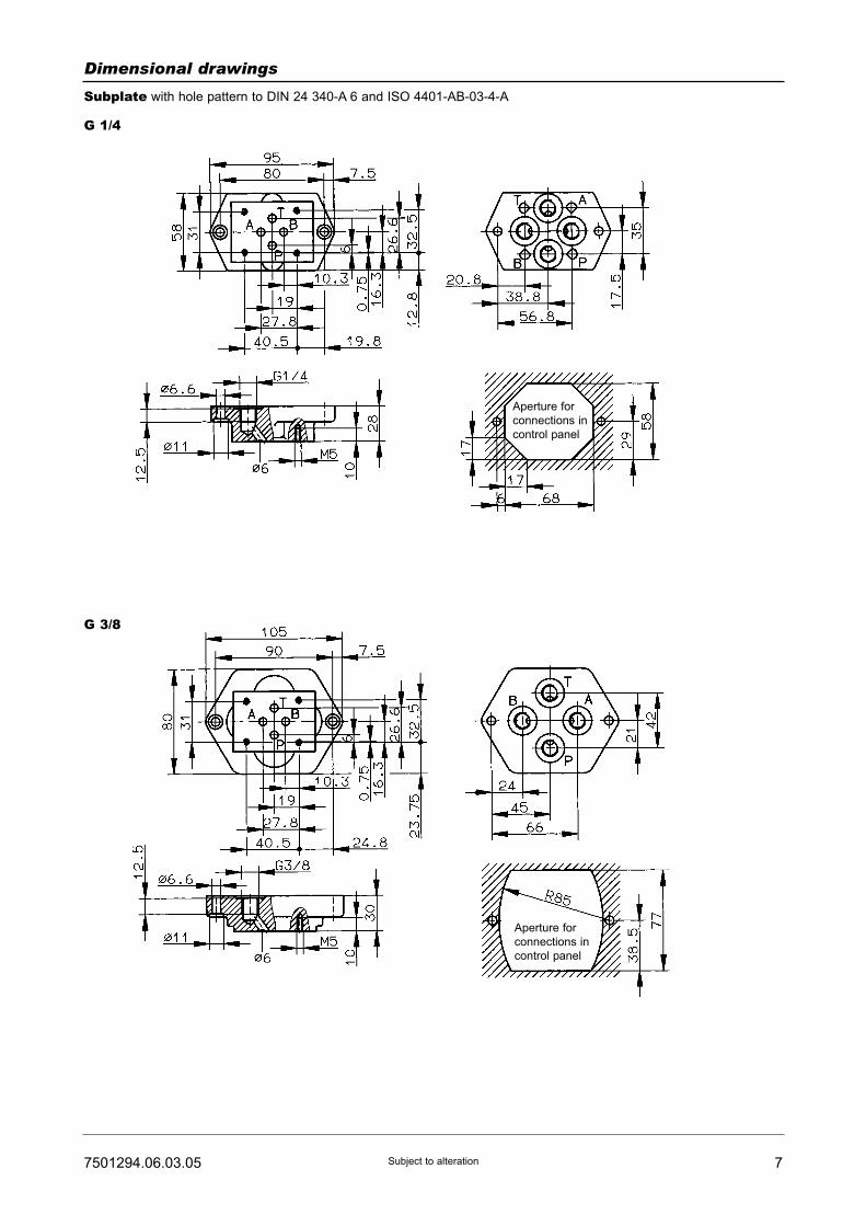
77501294.06.03.05 Subject to alteration
Dimensional drawings
Subplate with hole pattern to DIN 24 340-A 6 and ISO 4401-AB-03-4-A
G 1/4
G 3/8
Aperture for
connections in
control panel
Aperture for
connections in
control panel

8 7501294.06.03.05Subject to alteration
Spare parts drawings
S 6 V ...
3/2-way directional control valve4/2-way directional control valve
Code 210
S 6 V ...
4/2-way directional controlvalve
4/3-way directional controlvalve
Code 216
S 6 V ...
4/2-way directional control valve4/3-way directional control valve
Code 217

97501294.06.03.05 Subject to alteration
Spare parts drawings
S 6 V ...
4/3-way directional control valve
Code 220
S 6 V ...
3/2-way directional control valve4/2-way directional control valvewith mechanical detent
Code 222
S 6 V ...
3/2-way directional control valve4/2-way directional control valvewith mechanical detent
Code 223

10 7501294.06.03.05Subject to alteration
Spare parts (Number of pieces)
Part
1 O-ring (9,2 x 1,8) 4 4 4 4 07017282 O-ring (16 x 2) 2 3 or 4 3 4 06614763 DC solenoid
(state voltage)
1 1 or 2 2 2 72341)
4 Seal(U 5,7 x 9 x 1)
1 1 1 1 0660227
5 Inductivelimit switch
1 2 1 1 0615392
6 Connector 1 2 1 1 06155177 Spring 1 1 or 2 2 - 06150507 Spring - - - 2 06157638 Washer - - - 2 06615099 Ball ø 5 - - - 2 0700753
- Cylinder bolt(M 5 x 30 DIN 912-10.9)
4 4 4 4 0700387
3 For AC applicationsuse DC solenoidwith rectifier insertin connector(state voltage)
(Connector with recifier insert
see electrical spare parts)
72341)
S 6 VH 10 ...
S 6 VH 11 ...
S 6 VH 13 ...
Code 210 and 217
S 6 VH 10 ...
S 6 VH 11 ...
S 6 VH 13 ...
Code 216
S 6 VH 10 ...
S 6 VH 11 ...
S 6 VH 13 ...
Code 220
S 6 VH 10 ...
S 6 VH 11 ...
S 6 VH 13 ...
with mechanical detent
Code 222 and 223
Designation Cat. No.
Mounting bolts (valve) tightening torque MA = 7,6 Nm
1 set of spare partsconsists of parts:
1,2 and 4 1,2 and 4 1,2 and 4 1,2 and 4 -Electrical spare parts
1) Solenoid without manual override Cat. No. 7238

Directional control valvesDN 10 (NG 10)Directly actuatedInterface to DIN 24 340 and ISO 4401
PN [pmax.] = 315 bar
7501296.06.08.05
HERION Systemtechnik GmbHUntere Talstraße 65
D-71263 Weil der Stadt-Merklingen
Tel.: +49 (0) 70 33/30 18-0
Fax: +49 (0) 70 33/30 18-10
www.herion-systemtechnik.de
3 Symbol
Symbol SymbolNo.
0013)
003
020
004
005
0443)
039
0213)
019
025
+
-
+
+
+
+
+
+
+
+
0313)
038
035
002
008
009
010
011
013
016
+
+
+
-
+
+
+
-
-
+
Overlap Symbol SymbolNo.
Overlap
DesignThe design is based upon the 5-chamber system.A spool of hardened steel slides in a housing made ofhigh-strength cast-iron. Therefore the units are suitablefor rough operating conditions.
ActuationThe directional control valves can be actuated eitherelectromagnetically, electropneumatically, hydraulically,pneumatically, mechanically or by spring.
MountingThe units are bolted on subplates and sealed byO-rings.
Line connectionSubplate, interface to DIN 24340-A10 and ISO 4401-AC-05-4-A.
Description (standard units)
• Good guidance of the spool (5-chamber system)- this means reliable switching even with long restperiod
• No dynamic seals• Delay of switching time by exchangeable nozzle• Solenoids with pressure-tight core tube (tube secured)
to valve body by means of central thread). No need toopen pressure-tight space when replacing coil.
• Valves with Viton seals standard• Coils designed for DC voltage. AC operation via con-
nector equipped with rectifier.
Features
Type key
S 10 ... ... G ... 001 ... ... ...1 2 3 4 5 6
Directional control valve
1 Actuation: VH – DC-type solenoid, pressure-tight, with manual override
V – Without manual override
2 Electrical 10 – Connector Pg 11connection: to DIN 43650 on solenoid
11 – Connector Pg 11with rectifier insert on solenoid
12 – Connector Pg 11with rectifier insert and functionindicator on solenoid
13 – Connector Pg 11with function indicator onsolenoid
4 Engineering version: 6 – Wet solenoid provided withcentral thread
5 Additional data: O – Standard design
M1) – Mechanical detent
C2) – Switching delay by means ofnozzle
6 Sealing material: V – FKM (e.g. Viton)
1)2-position valves available with detent for all types of actutor, except roller tappet
(R). 3-position valve can only be arrested by means of a hand lever.2)
Port T of valves with a delayed switching time, must be pressurized with approx.
5 bar.3)
Port T of these 3/2 directional control valves is used as leak oil connection.

Type designation (Actuation) V(H) 10 V(H) 11
General parametersDesignation Directional control valve
Symbol See type survey or type key
Design Spool-type valve
Type of mounting Flange
Line connection Subplate
Mounting position Preferably horizontal
Weight of valve with 1 actuator [kg] 6,5
2 actuators 7,3
Weight of G 1/2 [kg] 2
subplate G 3/4 3,4
Ambient temperature range ϑu [°C] -20 to +50
Size DN 10
Hydraulic parametersOperating pressure pe max. [bar]
at port P, A, B up to 315
at port T up to 160
Pressure fluid temperature ϑm max. [°C] +70
Viscosity range ν [mm2/s] 12 to 500
Flow Qmax. [l/min] See characteristic curves
Filtration Oil purity class to ISO 4406: 18/15
Further parametersManual override Standard
Switching times, approx. [ms]
ton 70 to 95
toff 40 to 80
Number of switchings/h, approx. 15000
Rated voltage UN [V] Standard voltages
Connector input 24 VDC 230 VAC / 40 ... 60 HZ1)
±10% +5%/-10%
Further voltages on request
Power consumption P20 [W] 42
Duty cycle [%] 100
Degree of protection for solenoid and
electrical connection to DIN 40050 IP 65
2 7501296.06.08.05Subject to alteration
Parameter to VDI 3267
SubplateP S 10 G ... 001 ... O O
1 2
1 Line connection: 400 - G 1/2 (internal thread500 - G 3/4 to DIN ISO 228/1)
2 Code: 200
Type key
1) DC-type coil 205V and connector with rectifier

37501296.06.08.05 Subject to alteration
Characteristic curves
Power limits
Symbol
001
003
008
009
013
019
020
6
6
6
6
4
6
6
6
6
6
6
4
6
6
-
4
5
3
3
4
4
-
4
5
3
2
4
4
-
-
-
-
1
-
-
Flow direction
P-A P-B A-T B-T P-T
Symbol Characteristic curve
001
003
008
009
013
019
020
1
4
5
2
3
5
5
Maximum values determined with solenoid in warmed-up condition and at an undervoltage of 10%. Fluidpassing in two directions (from P to A and B to T). Ifone port is closed, a reduced breaking capacity must betaken into consideration. Further valves with differentswitching symbols available on request.
Ordering Example of order
The units are designated by their type number. Thecomposition of this number can be drawn from the typecode. The standard versions are listed in the typesurvey. When ordering any of the standard versions,please state type number as well as catalog number topreclude possible misinterpretations.Further valve versions can be composed via combi-nation of types. The catalog number of these devicesyou will get on request.Flanges valves are provided with O-rings and connector(type 10 or 11, Page 2). Subplate and mounting screwsmust be ordered separately.
Wanted: 4/3 directional control valve DN 10, 24 VDC,connector on solenoid, Symbol 008, along withcorresponding subplate G 1/4.
Directional control valve:Type No.: S 10 VH 10 G 008 001 6 O VCat. No.: 5204819.7908
Subplate:Type No.: P S 10 G 4 001 2 O OCat. No.: 1065184
Mounting screws: (4 pcs. required)Socket-head screw: (M 6 x 60 DIN 912-10.9)Cat. No.: 0700416
Flow curves ?p = f(Q)
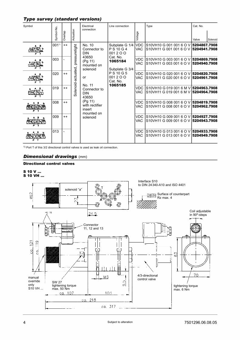
4 7501296.06.08.05Subject to alteration
Type survey (standard versions)
1) Port T of this 3/2 directional control valves is used as leak oil connection.
Sym
bo
l-N
o.
Ove
rla
p
Actu
atio
n
Vo
lta
ge
Symbol Electrical
connection
Line connection Type Cat. No.
Valve Solenoid
0011)
003
020
019
008
009
013
++
-
++
++
++
++
-
VDCVAC
VDCVAC
VDCVAC
VDCVAC
VDCVAC
VDCVAC
VDCVAC
S10VH10 G 001 001 6 O VS10VH11 G 001 001 6 O V
S10VH10 G 003 001 6 O VS10VH11 G 003 001 6 O V
S10VH10 G 020 001 6 O VS10VH11 G 020 001 6 O V
S10VH10 G 019 001 6 M VS10VH11 G 019 001 6 M V
S10VH10 G 008 001 6 O VS10VH11 G 008 001 6 O V
S10VH10 G 009 001 6 O VS10VH11 G 009 001 6 O V
S10VH10 G 013 001 6 O VS10VH11 G 013 001 6 O V
5204867.79085204941.7908
5204869.79085204940.7908
5204820.79085204961.7908
5204963.79085204964.7908
5204819.79085204962.7908
5204927.79085204943.7908
5204933.79085204949.7908
So
len
oid
-actu
ate
d,
pre
ssu
retig
ht No. 10
Connector toDIN43650(Pg 11)mounted onsolenoid
or
No. 11Connector toDIN43650(Pg 11)with rectifierinsertmounted onsolenoid
Subplate G 1/4P S 10 G 4001 2 O OCat. No.1065184
Subplate G 3/4P S 10 G 5001 2 O OCat. No.1065185
Dimensional drawings (mm)
Directional control valves
S 10 V ...S 10 VH ...
solenoid “a”
Interface S10to DIN 24340-A10 and ISO 4401
Surface of counterpartRz max. 4
Connector11, 12 and 13
Coil adjustablein 90o-steps
tightening torquemax. 6 Nm
4/3-directionalcontrol valve
SW 27tightening torquemax. 50 Nm
manualoverrideonlyS10 VH ...
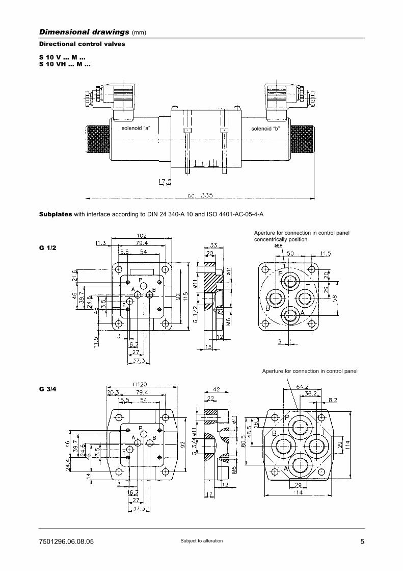
57501296.06.08.05 Subject to alteration
Subplates with interface according to DIN 24 340-A 10 and ISO 4401-AC-05-4-A
G 1/2
G 3/4
Dimensional drawings (mm)
Directional control valves
S 10 V ... M ...S 10 VH ... M ...
solenoid “a” solenoid “b”
Aperture for connection in control panel
Aperture for connection in control panel
concentrically position
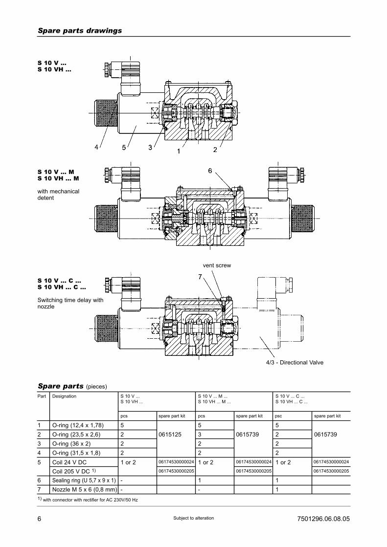
6 7501296.06.08.05Subject to alteration
Spare parts drawings
S 10 V ...S 10 VH ...
S 10 V ... MS 10 VH ... M
with mechanicaldetent
S 10 V ... C ...S 10 VH ... C ...
Switching time delay withnozzle
Spare parts (pieces)
Part
1 O-ring (12,4 x 1,78) 5 5
2 O-ring (23,5 x 2,6)
O-ring (36 x 2)
O-ring (31,5 x 1,8)
Coil 24 V DC
Coil 205 V DC 1)
2 0615125 3
3
4
5
2
2
1 or 2
2
2
5
2
2
2
1 or 21 or 206174530000024
06174530000205
06174530000024
06174530000205
06174530000024
06174530000205
0615739 0615739
S 10 V ...
S 10 VH ...
pcs spare part kit pcs spare part kit psc spare part kit
S 10 V ... M ...
S 10 VH ... M ...
S 10 V ... C ...
S 10 VH ... C ...
Designation
1) with connector with rectifier for AC 230V/50 Hz
vent screw
4/3 - Directional Valve
Sealing ring (U 5,7 x 9 x 1)
Nozzle M 5 x 6 (0,8 mm)
6
7
-
-
1
-
1
1
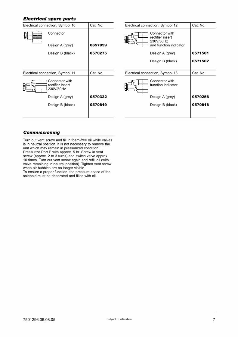
77501296.06.08.05 Subject to alteration
Electrical spare partsElectrical connection, Symbol 10 Cat. No.
Connector
Design A (grey) 0657859
Design B (black) 0570275
Electrical connection, Symbol 11 Cat. No.
Connector withrectifier insert230V/50Hz
Design A (grey) 0570322
Design B (black) 0570819
Electrical connection, Symbol 12 Cat. No.
Connector withrectifier insert230V/50Hzand function indicator
Design A (grey) 0571501
Design B (black) 0571502
Electrical connection, Symbol 13 Cat. No.
Connector withfunction indicator
Design A (grey) 0570256
Design B (black) 0570818
Commissioning
Turn out vent screw and fill in foam-free oil while valvesis in neutral position. It is not necessary to remove theunit which may remain in pressurized condition.Pressurize Port P with approx. 5 br. Screw in ventscrew (approx. 2 to 3 turns) and switch valve approx.10 times. Turn out vent screw again and refill oil (withvalve remaining in neutral position). Tighten vent screwwhen air bubbles are no longer visible.To ensure a proper function, the pressure space of thesolenoid must be deaerated and filled with oil.

8 7501296.06.08.05Subject to alteration
Notes:
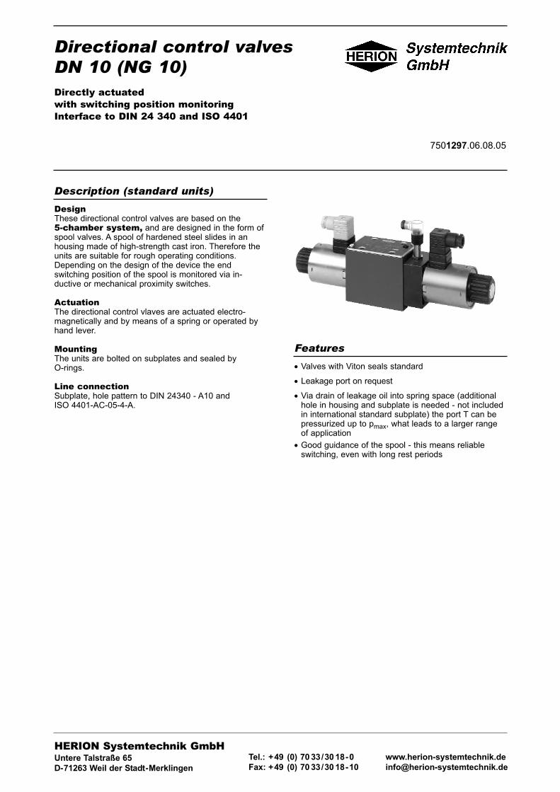
Directional control valvesDN 10 (NG 10)Directly actuatedwith switching position monitoringInterface to DIN 24 340 and ISO 4401
7501297.06.08.05
DesignThese directional control valves are based on the5-chamber system, and are designed in the form ofspool valves. A spool of hardened steel slides in anhousing made of high-strength cast iron. Therefore theunits are suitable for rough operating conditions.Depending on the design of the device the endswitching position of the spool is monitored via in-ductive or mechanical proximity switches.
ActuationThe directional control vlaves are actuated electro-magnetically and by means of a spring or operated byhand lever.
MountingThe units are bolted on subplates and sealed byO-rings.
Line connectionSubplate, hole pattern to DIN 24340 - A10 andISO 4401-AC-05-4-A.
Description (standard units)
• Valves with Viton seals standard
• Leakage port on request
• Via drain of leakage oil into spring space (additionalhole in housing and subplate is needed - not includedin international standard subplate) the port T can bepressurized up to pmax, what leads to a larger rangeof application
• Good guidance of the spool - this means reliableswitching, even with long rest periods
Features
HERION Systemtechnik GmbHUntere Talstraße 65
D-71263 Weil der Stadt-Merklingen
Tel.: +49 (0) 70 33/30 18-0
Fax: +49 (0) 70 33/30 18-10
www.herion-systemtechnik.de
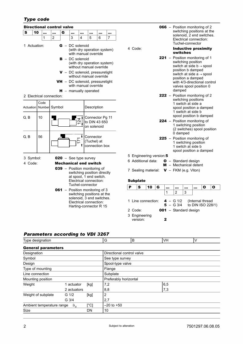
1 Actuation: G – DC solenoid(with dry operation system)with manual override
B – DC solenoid(with dry operation system)without manual override
V – DC solenoid, pressuretightwithout manual override
VH – DC solenoid, pressuretightwith manual override
H – manually operated
2 Electrical connection:
3 Symbol: 020 – See type survey
4 Code: Mechanical end switch039 – Position monitoring of
switching position directlyat spool, 1 end switch.Electrical connection:Tuchel-connector
061 – Position monitoring of 3switching positions at thesolenoid, 3 end switches.Electrical connection:Harting-connector R 15
2 7501297.06.08.05Subject to alteration
Type designation G B VH V
General parametersDesignation Directional control valve
Symbol See type survey
Design Spool-type valve
Type of mounting Flange
Line connection Subplate
Mounting position Preferably horizontal
Weight 1 actuator [kg] 7,2 6,5
2 actuators 8,8 7,3
Weight of subplate G 1/2 [kg] 2
G 3/4 2,7
Ambient temperature range ϑu [°C] –20 to +50
Size DN 10
Code
Actuation Number Symbol Description
G, B 10 Connector Pg 11
to DIN 43 650
on solenoid
G, B 56 Connector
(Tuchel) at
connection box
124
171
Type code
S 10 ... ... G ... ... ... ... ...1 2 3 4 5 6 7
Directional control valve
Parameters according to VDI 3267
066 – Position monitoring of 2switching positions at thesolenoid, 2 end switches.Electrical connection:Tuchel-connector
4 Code: Inductive proximityswitches
221 – Position monitoring of 1switching positionswitch at side b C spoolposition b dampedswitch at side a C spoolposition a dampedwith 4/3-directional controlvalves spool position 0damped
222 – Position monitoring of 2switching positions1 switch at side aspool position a damped1 switch at side bspool position b damped
224 – Position monitoring of1 switching position(2 switches) spool position0 damped
225 – Position monitoring of1 switching position1 switch at side bspool position a damped
5 Engineering version:56 Additional data: O – Standard design
M – Mechanical detent
7 Sealing material: V – FKM (e.g. Viton)
Subplate
1 Line connection: 4 – G 1/2 (Internal thread5 – G 3/4 to DIN ISO 228/1)
2 Code: 001 – Standard design
3 Engineeringversion: 2
P S 10 G ... ... ... ... O O1 2 3

37501297.06.08.05 Subject to alteration
Type designation G B VH V
Hydraulic parametersOperating pressure range pe max. [bar]
at port P, A, B ... 315
at port T (without leakage port) ... 100 ... 50 2)
at port T (with leakage port) ... 315 1) –
Pressure fluid temperature ϑm max. [°C] +70
Viscosity range ν [mm2/s] 12 ... 500
Flow Qmax (l/min) See characteristic curve
Filtration Oil purity class to ISO 4406: 18/15
Other parameters 1) on request; 2) > 50 bar on request
PIN assignment for Tuchel-connection:
Valve with 1 solenoid Solenoid ”a“ at 1 and 2 or –
Solenoid ”b“ at 3 and 4
Ground wire at
Valve with 2 solenoids Solenoid ”a“ at 1 and 2 –
Solenoid ”b“ at 3 and 4
Ground wire at
Switching times t approx. [ms]
(measured at 315 bar, ton 70 ... 951)
60 l/min) toff 70 ... 801)
Approx. number of switchings/h 15.000 (3600 for symbol 039)
Rated voltage UN [V] DC 24 ± 10 % (Other voltages available on request)
Power consumption P20 [W] 36 42
Duty cycle EDrel [%] 100
Degree of protection for solenoid and
electrical connection to DIN 40 050 IP 54 IP 65
Maunal override yes no yes no
Characteristic curves: flow curves: ?p = f(Q) Power limits Qmax:
Symbol
001
003
008, 004, 094
013
017
019
020, 039
177
6
1
1
3
-
1
1
1
6
1
1
3
6
1
1
1
-
3
5
2
2
3
3
3
-
3
5
7
-
3
3
-
-
-
-
8
8
-
-
-
Flow direction
P-A P-B A-T B-T P-T
Symbol Characteristic curve
001, 117
003
008, 004, 094, 017, 019
013, 020, 039
2
4
1
5
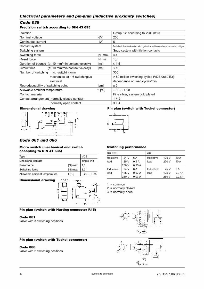
Isolation Group ”C“ according to VDE 0110
Nominal voltage ~[V] 250
Continuous current ~[A] 6
Contact system Dual-circuit directional contact with 2 galvanical and thermical separated contact bridges
Switching system Snap system with friction contacts
Switching force [N] max. 4,4
Reset force [N] min. 1,3
Duration of bounce (at 10 mm/min contact velocity) [ms] ≤ 1,5
Circuit time (at 10 mm/min contact velocity) [ms] ≤ 10
Number of switching max. switching/min 300
mechanical at 1,6 switchings/s > 50 million switching cycles (VDE 0660 E3)
electrical dependance on load cycles/min
Reproduceability of switching point [µm] ± 2
Allowable ambient temperature t [°C] – 30 ... + 90
Contact material Fine silver, system gold plated
Contact arrangement normally closed contact 1 + 2
normally open contact 3 + 4
4 7501297.06.08.05Subject to alteration
Precision switch according to DIN 43 695
Dimensional drawing Pin plan (switch with Tuchel connector)
Electrical parameters and pin-plan (inductive proximity switches)Code 039
Code 061 und 066Micro switch (mechanical end switchaccording to DIN 41 635)Type VCS
Directional contact single line
Reset force [N] max. 1,1
Switching force [N] max. 3,3
Allowable ambient temperature t [°C] – 20 ... + 85
Switching performance
DC === AC ~
Resistive 24 V 6 A Resistive 125 V 10 A
load 125 V 0,5 A load 250 V 10 A
250 V 0,25 A
Inductive 24 V 6 A Inductive 25 V 6 A
load 125 V 0,07 A load 125 V 0,07 A
250 V 0,03 A 250 V 0,03 A
Dimensional drawing1 = common
2 = normally closed
3 = normally open
Pin plan (switch with Harting-connector R15)
Code 061Valve with 3 switching positions
Pin plan (switch with Tuchel-connector)
Code 066Valve with 2 switching positions
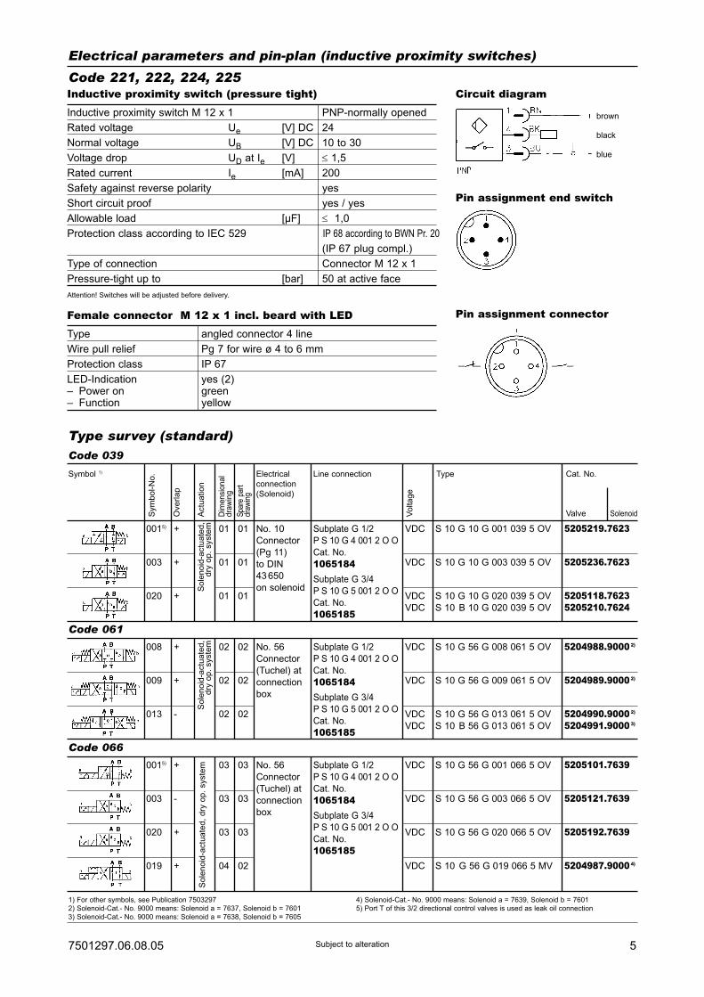
57501297.06.08.05 Subject to alteration
Electrical parameters and pin-plan (inductive proximity switches)Code 221, 222, 224, 225Inductive proximity switch (pressure tight)Inductive proximity switch M 12 x 1 PNP-normally opened
Rated voltage Ue [V] DC 24
Normal voltage UB [V] DC 10 to 30
Voltage drop UD at Ie [V] ≤ 1,5
Rated current Ie [mA] 200
Safety against reverse polarity yes
Short circuit proof yes / yes
Allowable load [µF] ≤ 1,0
Protection class according to IEC 529 IP 68 according to BWN Pr. 20
(IP 67 plug compl.)
Type of connection Connector M 12 x 1
Pressure-tight up to [bar] 50 at active face
Attention! Switches will be adjusted before delivery.
Female connector M 12 x 1 incl. beard with LEDType angled connector 4 line
Wire pull relief Pg 7 for wire ø 4 to 6 mm
Protection class IP 67
LED-Indication yes (2)– Power on green– Function yellow
Pin assignment connector
Circuit diagram
Pin assignment end switch
Type survey (standard)
1) For other symbols, see Publication 7503297
2) Solenoid-Cat.- No. 9000 means: Solenoid a = 7637, Solenoid b = 7601
3) Solenoid-Cat.- No. 9000 means: Solenoid a = 7638, Solenoid b = 7605
4) Solenoid-Cat.- No. 9000 means: Solenoid a = 7639, Solenoid b = 7601
5) Port T of this 3/2 directional control valves is used as leak oil connection
Sym
bo
l-N
o.
Ove
rla
p
Actu
atio
n
Dim
ensi
onal
dra
win
g
Spa
re p
art
draw
ing
Vo
lta
ge
Symbol 1) Electrical
connection
(Solenoid)
Line connection Type Cat. No.
Valve Solenoid
0015) 01
01
01
01
01
01
003
020
+
+
+
VDC
VDC
VDC
VDC
S 10 G 10 G 001 039 5 OV
S 10 G 10 G 003 039 5 OV
S 10 G 10 G 020 039 5 OV
S 10 B 10 G 020 039 5 OV
5205219.7623
5205236.7623
5205118.76235205210.7624
So
len
oid
-actu
ate
d,
dry
op
. syste
m No. 10
Connector
(Pg 11)
to DIN
43 650
on solenoid
Subplate G 1/2
P S 10 G 4 001 2 O O
Cat. No.
1065184Subplate G 3/4
P S 10 G 5 001 2 O O
Cat. No.
1065185
Code 039
008 02
02
02
02
02
02
009
013
+
+
-
VDC
VDC
VDC
VDC
S 10 G 56 G 008 061 5 OV
S 10 G 56 G 009 061 5 OV
S 10 G 56 G 013 061 5 OV
S 10 B 56 G 013 061 5 OV
5204988.9000 2)
5204989.9000 2)
5204990.9000 2)
5204991.9000 3)
So
len
oid
-actu
ate
d,
dry
op
. syste
m No. 56
Connector
(Tuchel) at
connection
box
Subplate G 1/2
P S 10 G 4 001 2 O O
Cat. No.
1065184Subplate G 3/4
P S 10 G 5 001 2 O O
Cat. No.
1065185
Code 061
0015) 03
03
03
04
03
03
03
02
003
020
019
+
-
+
+
VDC
VDC
VDC
VDC
S 10 G 56 G 001 066 5 OV
S 10 G 56 G 003 066 5 OV
S 10 G 56 G 020 066 5 OV
S 10 G 56 G 019 066 5 MV
5205101.7639
5205121.7639
5205192.7639
5204987.9000 4)
So
len
oid
-actu
ate
d,
dry
op
. syste
m No. 56
Connector
(Tuchel) at
connection
box
Subplate G 1/2
P S 10 G 4 001 2 O O
Cat. No.
1065184Subplate G 3/4
P S 10 G 5 001 2 O O
Cat. No.
1065185
Code 066
brown
black
blue
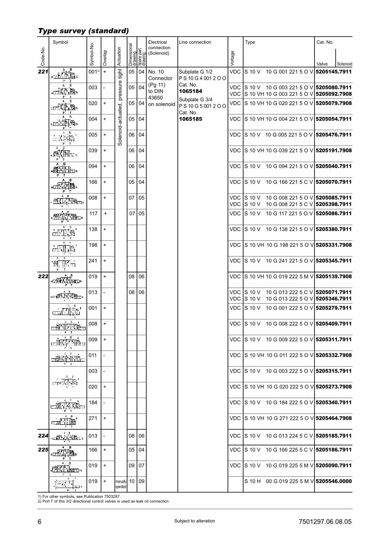
6 7501297.06.08.05Subject to alteration
Type survey (standard)
Sym
bo
l-N
o.
Co
de
-No
.
Ove
rla
p
Actu
atio
n
Dim
ensi
onal
dra
win
gS
pare
par
tdr
awin
g
Vo
lta
ge
Symbol Electrical
connection
(Solenoid)
Line connection Type Cat. No.
Valve Solenoid
0012) 05
05
05
05
06
06
06
05
07
07
08
08
08
05
09
10
04
04
04
04
04
04
04
04
05
05
06
06
06
04
07
09
003
020
004
005
039
094
166
008
117
019
013
013
166
019
019
+
-
+
+
+
+
+
+
+
+
+
-
-
+
+
+
VDC
VDC
VDC
VDC
VDC
VDC
VDC
VDC
VDC
VDC
VDC
VDC
VDC
VDC
VDC
VDC
VDC
VDC
S 10 V 10 G 001 221 5 O V
S 10 V 10 G 003 221 5 O V
S 10 VH 10 G 003 221 5 O V
S 10 VH 10 G 020 221 5 O V
S 10 VH 10 G 004 221 5 O V
S 10 V 10 G 005 221 5 O V
S 10 VH 10 G 039 221 5 O V
S 10 V 10 G 094 221 5 O V
S 10 V 10 G 166 221 5 C V
S 10 V 10 G 008 221 5 O V
S 10 V 10 G 008 221 5 C V
S 10 V 10 G 117 221 5 O V
S 10 VH 10 G 019 222 5 M V
S 10 V 10 G 013 222 5 C V
S 10 V 10 G 013 222 5 O V
S 10 V 10 G 013 224 5 C V
S 10 V 10 G 166 225 5 C V
S 10 V 10 G 019 225 5 M V
S 10 H 00 G 019 225 5 M V
5205145.7911
5205080.79115205092.7908
5205079.7908
5205054.7911
5205476.7911
5205191.7908
5205040.7911
5205070.7911
5205085.79115205398.7911
5205086.7911
07 05138 + VDC S 10 V 10 G 138 221 5 O V 5205380.7911
07 05198 + VDC S 10 VH 10 G 198 221 5 O V 5205331.7908
07 05241 + VDC S 10 V 10 G 241 221 5 O V 5205345.7911
5205139.7908
5205071.79115205346.7911
08 06001 + VDC S 10 V 10 G 001 222 5 O V 5205279.7911
08 06008 + VDC S 10 V 10 G 008 222 5 O V 5205409.7911
08 06009 + VDC S 10 V 10 G 009 222 5 O V 5205311.7911
08 06011 - VDC S 10 VH 10 G 011 222 5 O V 5205332.7908
08 06003 - VDC S 10 V 10 G 003 222 5 O V 5205315.7911
08 06020 + VDC S 10 VH 10 G 020 222 5 O V 5205273.7908
08 06184 - VDC S 10 V 10 G 184 222 5 O V 5205340.7911
08 06271 + VDC S 10 VH 10 G 271 222 5 O V 5205464.7908
5205185.7911
5205186.7911
5205090.7911
5205546.0000
So
len
oid
-actu
ate
d,
pre
ssu
re t
igh
t
No. 10
Connector
(Pg 11)
to DIN
43650
on solenoid
Subplate G 1/2
P S 10 G 4 001 2 O O
Cat. No.
1065184Subplate G 3/4
P S 10 G 5 001 2 O O
Cat. No.
1065185
221
222
224
225
1) For other symbols, see Publication 7503297.
2) Port T of this 3/2 directional control valves is used as leak oil connection
manuallyoperated

77501297.06.08.05 Subject to alteration
Ordering Example of orderThe units are designated by their type number. Thecomposition of this number can be drawn from the typecode. The standard versions are listed in the typesurvey. When ordering any of the standard versions,please state type number as well as catalog number topreclude possible misinterpretations.Further valve versions can be composed via combi-nation of types. The catalog number of these devicesyou will get on request.Flanges valves are provided with O-rings andconnector. Subplate and mounting screws must beordered separately.
Wanted: 4/2 directional control valve DN 10, 24 VDC,connector on solenoid, Symbol 020, along withcorresponding subplate.
Directional control valve:Type No.: S 10 G 10 G 020 039 5 O VCat. No.: 5205118.7623
Subplate:Type No.: P S 10 G 4 001 2 O OCat. No.: 1065184
Mounting screws: (4 pcs. required)Socket-head screw: (M 6 x 60 DIN 912-10.9)Cat. No.: 0700416
Dimensional drawings01 Code 039: S 10 G, S 10 B, 3/2- and
4/2-directional control valve04 Code 066: S 10 G with mechanical detent,
4/2-directional control valve
02 Code 061: S 10 G, S 10 B,4/3-directional control valve
05 Code 221: S 10 V, S 10 VH, 3/2- and4/2-directional control valve,
Code 225: S 10 V, S 10 VH,4/2-directional control valve
03 Code 066: S 10 G, 3/2- and4/2-directional control valve
06 Code 221: S 10 V, S 10 VH,4/2-directional control valve
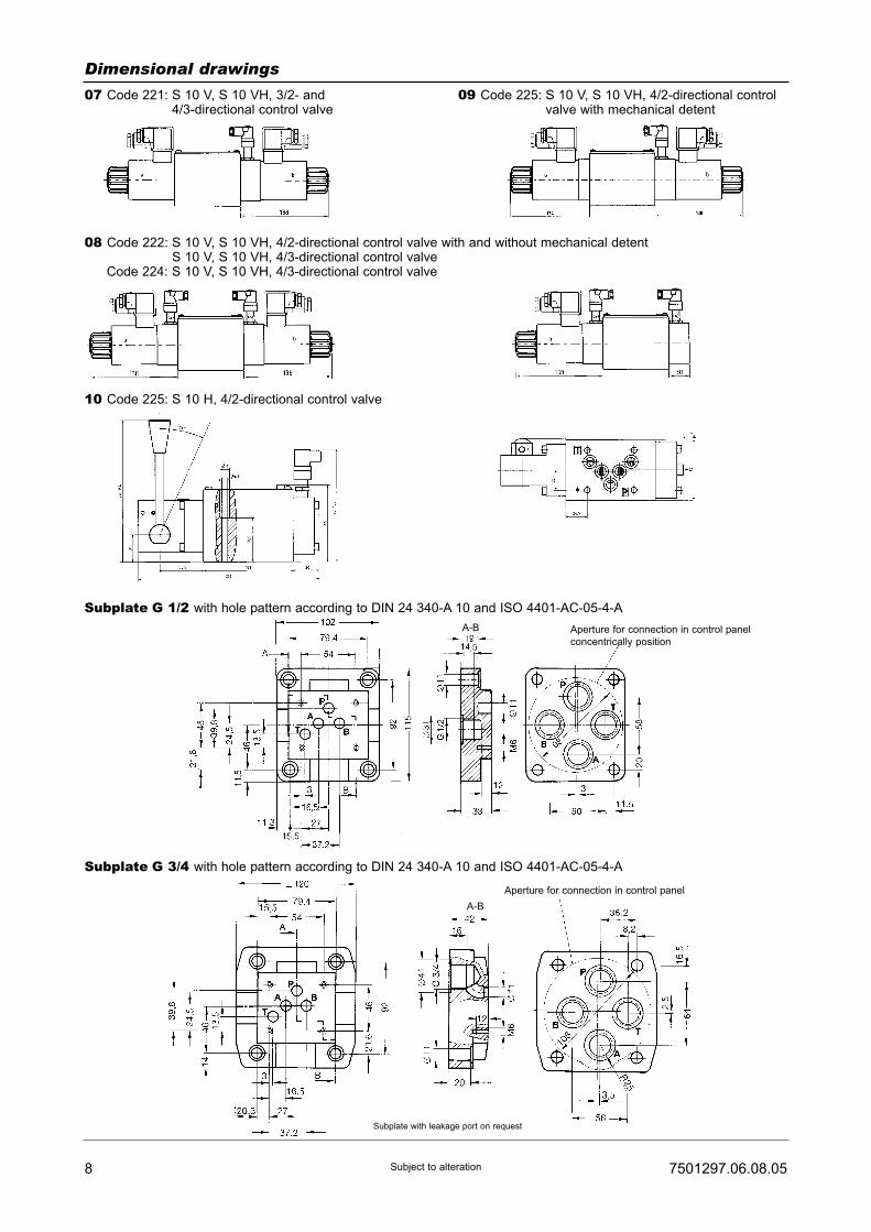
8 7501297.06.08.05Subject to alteration
A-B Aperture for connection in control panel
concentrically position
A-B
Aperture for connection in control panel
Subplate with leakage port on request
Dimensional drawings07 Code 221: S 10 V, S 10 VH, 3/2- and
4/3-directional control valve
08 Code 222: S 10 V, S 10 VH, 4/2-directional control valve with and without mechanical detentS 10 V, S 10 VH, 4/3-directional control valve
Code 224: S 10 V, S 10 VH, 4/3-directional control valve
10 Code 225: S 10 H, 4/2-directional control valve
09 Code 225: S 10 V, S 10 VH, 4/2-directional controlvalve with mechanical detent
Subplate G 1/2 with hole pattern according to DIN 24 340-A 10 and ISO 4401-AC-05-4-A
Subplate G 3/4 with hole pattern according to DIN 24 340-A 10 and ISO 4401-AC-05-4-A
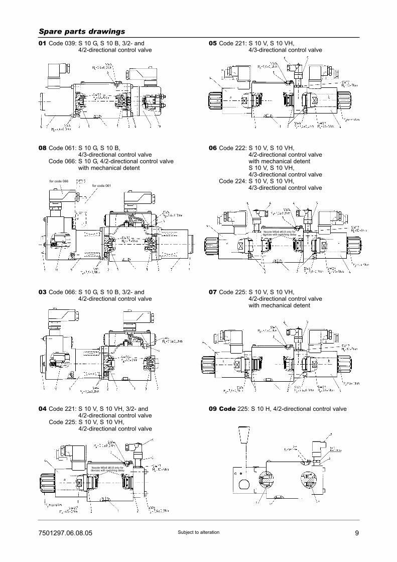
97501297.06.08.05 Subject to alteration
Spare parts drawings01 Code 039: S 10 G, S 10 B, 3/2- and
4/2-directional control valve05 Code 221: S 10 V, S 10 VH,
4/3-directional control valve
08 Code 061: S 10 G, S 10 B,4/3-directional control valve
Code 066: S 10 G, 4/2-directional control valvewith mechanical detent
06 Code 222: S 10 V, S 10 VH,4/2-directional control valvewith mechanical detentS 10 V, S 10 VH,4/3-directional control valve
Code 224: S 10 V, S 10 VH,4/3-directional control valve
03 Code 066: S 10 G, S 10 B, 3/2- and4/2-directional control valve
07 Code 225: S 10 V, S 10 VH,4/2-directional control valvewith mechanical detent
04 Code 221: S 10 V, S 10 VH, 3/2- and4/2-directional control valve
Code 225: S 10 V, S 10 VH,4/2-directional control valve
for code 066
for code 061
Nozzle M5x6 ø0,8 only fordevices with switching delay
Nozzle M5x6 ø0,8 only fordevices with switching delay
09 Code 225: S 10 H, 4/2-directional control valve
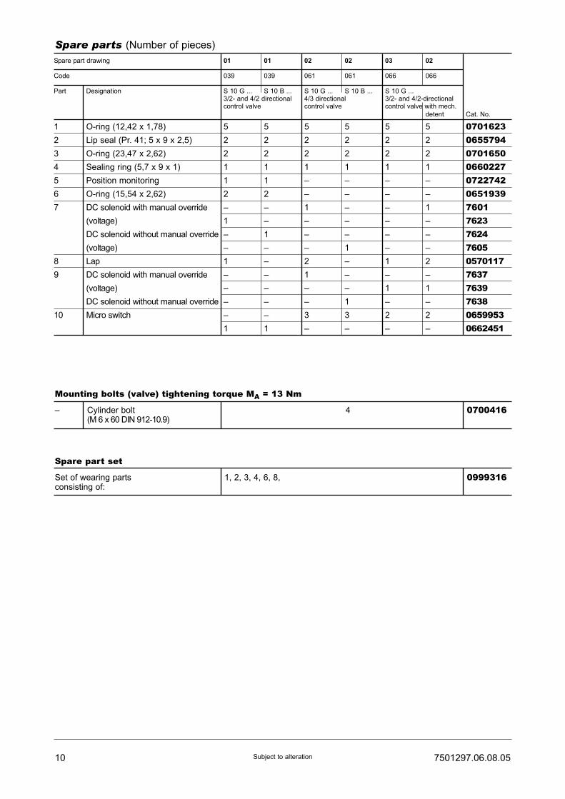
10 7501297.06.08.05Subject to alteration
Spare parts (Number of pieces)
Spare part drawing 01 01 02 02 03 02
Code 039 039 061 061 066 066
Part Designation S 10 G ... S 10 B ... S 10 G ... S 10 B ... S 10 G ...3/2- and 4/2 directional 4/3 directional 3/2- and 4/2-directionalcontrol valve control valve control valve with mech.
detent Cat. No.
1 O-ring (12,42 x 1,78) 5 5 5 5 5 5 07016232 Lip seal (Pr. 41; 5 x 9 x 2,5) 2 2 2 2 2 2 06557943 O-ring (23,47 x 2,62) 2 2 2 2 2 2 07016504 Sealing ring (5,7 x 9 x 1) 1 1 1 1 1 1 06602275 Position monitoring 1 1 – – – – 07227426 O-ring (15,54 x 2,62) 2 2 – – – – 06519397 DC solenoid with manual override – – 1 – – 1 7601
(voltage) 1 – – – – – 7623DC solenoid without manual override – 1 – – – – 7624(voltage) – – – 1 – – 7605
8 Lap 1 – 2 – 1 2 05701179 DC solenoid with manual override – – 1 – – – 7637
(voltage) – – – – 1 1 7639DC solenoid without manual override – – – 1 – – 7638
10 Micro switch – – 3 3 2 2 06599531 1 – – – – 0662451
Mounting bolts (valve) tightening torque MA = 13 Nm
– Cylinder bolt 4 0700416(M 6 x 60 DIN 912-10.9)
Spare part set
Set of wearing parts 1, 2, 3, 4, 6, 8, 0999316consisting of:

117501297.06.08.05 Subject to alteration
Electrical spare partsElectrical connection, Symbol 10 Cat. No.
Female connector
Design A (grey) 0657859
Design B (black) 0570275
e. g. at solenoid 7637 or 7638 Cat. No.
Circular plug-in connector:
Number of poles: 7 + PE 0570722
Electrical connection, Symbol 56 Cat. No.
Flange connector:
Number of poles: 4 + PE 0499980
Male connector: 1)
Number of poles: 4 + PE 0570290
1) not included
Spare parts (Number of pieces)
Spare part drawing 04 05 06 06 04 07 09
Code 221 221 222 224 225 225 225
Part Designation S 10 V ... S 10 V ... S 10 V ... S 10 V ... S 10 V ... S 10 V ... S 10 H ...S 10 VH ... S 10 VH ... S 10 VH ... S 10 VH ... S 10 VH ... S 10 VH ... 4/2-directional3/2- and 4/2 4/3 4/2-directional 4/3-- 3/2- 3/2- and control valvedirectional directional control valve directional directional 4/2-directional with mech.control control with and control control control valve dententvalve valve without valve valve with mech.
mech. detent dentent Cat. No.
1 O-ring (12,42 x 1,78) 5 5 5 5 5 5 5 07016232 O-ring (23,47 x 2,62) 2 3 4 4 2 4 2 07016503 Sealing ring (5,7 x 9 x 1) 1 1 1 1 1 1 1 06602274 DC solenoid without manual 1 2 2 2 1 2 - 7911
override
(voltage)
DC solenoid with manual 1 2 2 2 1 2 - 7908override
(voltage)
5 Inductive proximity switch 1 1 2 2 1 1 1 06153926 Angled socket compl. 1 1 2 2 1 1 1 0615517
Mounting bolts (valve) tightening torque MA = 13 Nm
– Cylinder bolt 4 0700416(M 6 x 60 DIN 912-10.9)
Spare part set
Set of wearing parts 1, 2, 3 0999317consisting of:

12 7501297.06.08.05Subject to alteration
Notes:
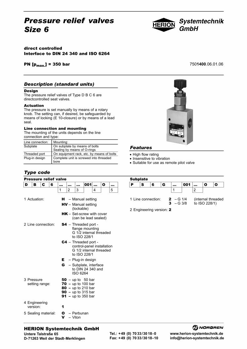
Line connection: Mounting:
Subplate On subplate by means of boltsSealing by means of O-rings
Threaded port On equipment rack, etc. by means of bolts
Plug-in design Complete unit is screwed into threadedbore
Pressure relief valvesSize 6
direct controlledInterface to DIN 24 340 and ISO 6264
PN [pmax.] = 350 bar 7501400.06.01.06
DesignThe pressure relief valves of Type D B C 6 aredirectcontrolled seat valves.
ActuationThe pressure is set manually by means of a rotaryknob. The setting can, if desired, be safeguarded bymeans of locking (E 10-closure) or by means of a leadseal.
Line connection and mountingThe mounting of the units depends on the lineconnection and type:
• High flow rating• Insensitive to vibration• Suitable for use as remote pilot valve
Description (standard units)
Features
Type codePressure relief valveD B C 6 ... ... ... 001 ... O ...
1 2 3 4 5
SubplateP S 6 G ... 001 ... O O
1 2
1 Actuation: H – Manual setting
HV – Manual setting(lockable)
HK – Set-screw with cover(can be lead sealed)
2 Line connection: S4 – Threaded port -flange mountingG 1/2 internal threadedto ISO 228/1
C4 – Threaded port -control-panel installationG 1/2 internal threadedto ISO 228/1
E – Plug-in design
G – Subplate, interfaceto DIN 24 340 andISO 6264
3 Pressure 50 – up to 150 barsetting range: 70 – up to 100 bar
80 – up to 210 bar90 – up to 315 bar91 – up to 350 bar
4 Engineeringversion: 1
5 Sealing material: O – PerbunanV – Viton
1 Line connection: 2 – G 1/4 (internal threaded3 – G 3/8 to ISO 228/1)
2 Engineering version: 2
HERION Systemtechnik GmbHUntere Talstraße 65
D-71263 Weil der Stadt-Merklingen
Tel.: +49 (0) 70 33/30 18-0
Fax: +49 (0) 70 33/30 18-10
www.herion-systemtechnik.de

Type designation D B C 6..S4.. D B C 6..C4.. D B C 6..E.. D B C 6..G..
General parametersDesignation Pressure relief valve
Symbol
Design Seat valve, direct-controlled
Type of mounting Flange Switch board Plug-in design Flange
installation
Line connection Thread Subplate
Mounting position Optional
Flow direction From P to T
Actuation By hand
Weight [kg] 2.4 3.0 0.7 2
Weight of subplate [kg] - 0.7
Ambienttemperature range ϑu [°C] –20 to +50
Size NG 6
Hydraulic parametersOperating pressure range pe max. [bar] up to 350
Adjustable pressure range pv [bar] pv min.: see characteristic curvepv max.: Pressure stage: 50: 150Pressure stage: 70: 100Pressure stage: 80: 210Pressure stage: 90: 315Pressure stage: 91: 350
Pressure fluid temperature ϑm max. [°C] +70
Viscosity range ν [mm2/s] 12 to 500
Flow Q [l/min] See characteristic curve
2 7501400.06.01.06Subject to alteration
Parameters to VDI 3276
Characteristic curves
pv min. = smallest adjustable pressure under which valve remains closedby pressure spring Q = 0 (l/min).

37501400.06.01.06 Subject to alteration
The units are designated by their type number. Thecomposition of this number can be drawn from the typecode. The standard versions are listed in the typesurvey. When ordering any of the standard versions,please state type number as well as catalog number topreclude possible misinterpretations.When inquiring about or ordering units not listed in ourtype survey of this publication, the type number madeup by you by means of the type code, however, will do.The corresponding catalog number will then be statedin our confirmation of order. Units with flanged connec-tion are delivered complete with mounting bolts andO-rings. The subplate must be ordered separately.
Wanted: Pressure relief valve size 6 with threaded portfor switch board installation, with manual setting, settingpressure max. 315 bar
Pressure relief valve:Type No.: D B C 6 H C4 90 001 1 O OCat. No.: 6014167
Ordering
Type survey (standard versions)
Example of order
Dimensional drawings
Size
6
Q[l/min]
Seecharac-teristiccurve
pv max.[bar]
125
150
100
210
315
350
150
100
210
315
350
150
100
210
315
350
150
100
210
315
350
Actuation
Manual setting
Type
D B C 6 H S4 25 001 1 O O
D B C 6 H S4 50 001 1 O O
D B C 6 H S4 70 001 1 OO
D B C 6 H S4 80 001 1 OO
D B C 6 H S4 90 001 1 OO
D B C 6 H S4 91 001 1 OO
D B C 6 H C4 50 001 1 OO
D B C 6 H C4 70 001 1 OO
D B C 6 H C4 80 001 1 OO
D B C 6 H C4 90 001 1 OO
D B C 6 H C4 91 001 1 OO
D B C 6 H E 50 001 1 OO
D B C 6 H E 70 001 1 OO
D B C 6 H E 80 001 1 OO
D B C 6 H E 90 001 1 OO
D B C 6 H E 91 001 1 OO
D B C 6 H G 50 001 1 OO
D B C 6 H G 70 001 1 OO
D B C 6 H G 80 001 1 OO
D B C 6 H G 90 001 1 OO
D B C 6 H C4 91 001 1 OO
Cat. No.
6014578601419860141996014201601416660144076014202601420360142046014167auf Anfrage
6014192601419360141946014164601447360144436014444601444560144396015310
Line connection
Threaded connectionFlange mounting
Threaded connectionSwitch board installation
Plug-in connection
Subplate G 1/4P S 6 G 2 001 2 O O1065173Subplate G 3/8P S 6 G 3 001 2 O O1065183
D B C 6 H S4... D B C 6 HV S4...
D B C 6 HK S4...
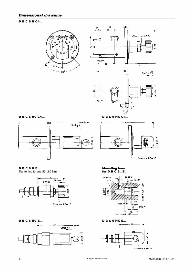
4 7501400.06.01.06Subject to alteration
Dimensional drawings
D B C 6 H C4...
D B C 6 HV C4... D B C 6 HK C4...
D B C 6 H E...Tightening torque 50...60 Nm
Mounting borefor D B C 6...E...
D B C 6 HV E... D B C 6 HK E...

57501400.06.01.06 Subject to alteration
Dimensional drawings
Pressure relief valveD B C 6 HK G...
Subpaltewith hole pattern to DIN 24340-C6-2and ISO 2664-AB-03-4-CG 1/4
G 3/8
D B C 6 HV G... D B C 6 H G...
Recess for
connections in
control panel
Recess for
connections in
control panel
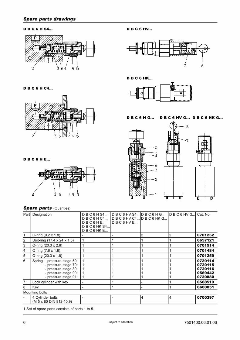
6 7501400.06.01.06Subject to alteration
Spare parts drawings
D B C 6 H S4... D B C 6 HV...
D B C 6 H C4...
D B C 6 H E...
D B C 6 HK...
D B C 6 H G... D B C 6 HV G... D B C 6 HK G...
Designation
O-ring (9.2 x 1.8)
Usit-ring (17.4 x 24 x 1.5)
O-ring (20.3 x 2.6)
O-ring (7.6 x 1.8)
O-ring (20.3 x 1.8)
Spring - pressure stage 50:- pressure stage 70:- pressure stage 80:- pressure stage 90:- pressure stage 91:
Lock cylinder with key
Key
4 Cylinder bolts(M 5 x 80 DIN 912-10.9)
Part
1
2
3
4
5
6
7
8
Mounting bolts
-
Spare parts (Quanties)
D B C 6 H S4...D B C 6 H C4...D B C 6 H E...D B C 6 HK S4...D B C 6 HK E...
-
1
1
1
1
11111
-
-
-
D B C 6 HV S4...D B C 6 HV C4...D B C 6 HV E...
-
1
1
1
1
11111
1
1
-
D B C 6 H G...D B C 6 HK G...
2
1
1
1
1
11111
-
-
4
D B C 6 HV G...
2
1
1
1
1
11111
1
1
4
Cat. No.
070125206571210701514070148407012590720114072011507201160569442072088005685190660051
0700397
1 Set of spare parts consists of parts 1 to 5.
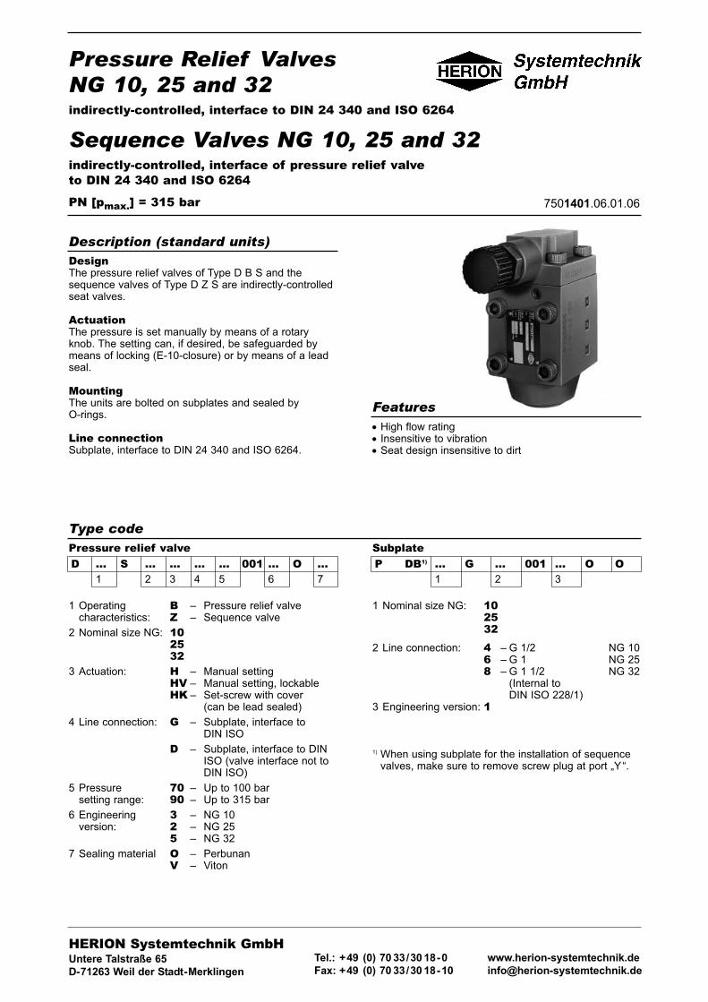
Pressure Relief ValvesNG 10, 25 and 32indirectly-controlled, interface to DIN 24 340 and ISO 6264
Sequence Valves NG 10, 25 and 32indirectly-controlled, interface of pressure relief valveto DIN 24 340 and ISO 6264
PN [pmax.] = 315 bar 7501401.06.01.06
DesignThe pressure relief valves of Type D B S and thesequence valves of Type D Z S are indirectly-controlledseat valves.
ActuationThe pressure is set manually by means of a rotaryknob. The setting can, if desired, be safeguarded bymeans of locking (E-10-closure) or by means of a leadseal.
MountingThe units are bolted on subplates and sealed byO-rings.
Line connectionSubplate, interface to DIN 24 340 and ISO 6264.
Description (standard units)
Type codePressure relief valveD ... S ... ... ... ... 001 ... O ...
1 2 3 4 5 6 7
SubplateP DB1) ... G ... 001 ... O O
1 2 3
1 Operating B – Pressure relief valvecharacteristics: Z – Sequence valve
2 Nominal size NG: 102532
3 Actuation: H – Manual settingHV – Manual setting, lockableHK – Set-screw with cover
(can be lead sealed)
4 Line connection: G – Subplate, interface toDIN ISO
D – Subplate, interface to DINISO (valve interface not toDIN ISO)
5 Pressure 70 – Up to 100 barsetting range: 90 – Up to 315 bar
6 Engineering 3 – NG 10version: 2 – NG 25
5 – NG 32
7 Sealing material O – PerbunanV – Viton
1 Nominal size NG: 102532
2 Line connection: 4 – G 1/2 NG 106 – G 1 NG 258 – G 1 1/2 NG 32
(Internal toDIN ISO 228/1)
3 Engineering version: 1
1) When using subplate for the installation of sequencevalves, make sure to remove screw plug at port „Y“.
HERION Systemtechnik GmbHUntere Talstraße 65
D-71263 Weil der Stadt-Merklingen
Tel.: +49 (0) 70 33/30 18-0
Fax: +49 (0) 70 33/30 18-10
www.herion-systemtechnik.de
• High flow rating• Insensitive to vibration• Seat design insensitive to dirt
Features

Type designation D B S 10..G. D B S 25..G. D B S 32..G. D Z S 10..G. D Z S 25..G. D Z S 32..G.
General parametersDesignation Pressure relief valve Sequence valve
Symbol
complete
simplified
Design Seat valve, indirectly-controlled
Type of mounting Flange
Line connection Subplate
Mounting position Optional
Flow direction From P to T
Actuation Manual setting
Weight [kg] 6,5 8,6 14,2 6,5 8,6 14,2
Weight of subplate [kg] 2 4,7 17,5 2 4,7 17,5
Ambienttemperature range ϑu [°C] –20 ... +50
Nominal size NG 10 25 32 10 25 32
Hydraulic parametersOperating pressure range pe [bar] ... 315
Adjustable pressure pv [bar] pv min.: see characteristic curverange pv max.: pressure stage 70: ... 100
pressure stage 90: ... 315
Pressure fluid temperature ϑm max. [°C] +70
Viscosity range ν [mm2/s] 12 ... 500
Flow Q [l/min] See characteristic curves
Control oil QSt [l/min] 0,5 See characteristic curve QSt
2 7501401.06.01.06Subject to alteration
Parameters according to VDI 3276
Characteristic curves
(Only for sequence valves)
Values for pv min. refer to external drain of control oil, e.g.when using a remote pilot control and pressure at T = 0 bar.

37501401.06.01.06 Subject to alteration
The units are designated by their type number. Thecomposition of this number can be drawn from the typecode. The standard versions are listed in the typesurvey. When ordering any of the standard versions,please state type number as well as catalog number topreclude possible misinterpretations. When inquiringabout or ordering units not listed in our type survey ofthis publication, the type number made up by you bymeans of the type code, however, will do. Thecorresponding catalog number will then be stated in ourconfirmation of order.The subplate and, if necessary, mounting material forvalve combinations must be ordered separately. OnlyO-rings are included in the delivery.
Wanted: Sequence valve NG 10 for flanged mountingwith manual setting. Setting pressure max. 315 bar,with mating subplate.
Sequence valve:Type No.: D Z S 10 H D 90 001 3 OOCat. No.: 6015324
Subplate:Type No: P DB 10 G 4 001 1 OOCat. No.: 2852600
Ordering
Type survey (standard design)
Example of how to order
NG
10
25
32
Q[l/min]
Seecharac-teristiccurve
pv max.[bar]
100315
100315
100315
Actuation
Manual setting
Line connection
Subplate G 1/2P DB 10 G 4 001 1 O O2852600Subplate G 1P DB 25 G 6 001 1 O O2852400Subplate G 1 1/2P DB 32 G 8 001 1 O O2840125
Type
D B S 10 H G 70 001 3 OOD B S 10 H G 90 001 3 OO
D B S 25 H G 70 001 2 OOD B S 25 H G 90 001 2 OO
D B S 32 H G 70 001 5 OOD B S 32 H G 90 001 5 OO
Cat. No.
60153216015322
60153896015390
60154596015460
NG
10
25
32
Q[l/min]
Seecharac-teristiccurve
pv max.[bar]
100315
100315
100315
Actuation
Manual setting
Line connection
Subplate G 1/2P DB 10 G 4 001 1 O O2852600Subplate G 1P DB 25 G 6 001 1 O O2852400Subplate G 1 1/2P DB 32 G 8 001 1 O O2840125
Type
D Z S 10 H D 70 001 3 OOD Z S 10 H D 90 001 3 OO
D Z S 25 H D 70 001 2 OOD Z S 25 H D 90 001 2 OO
D Z S 32 H D 70 001 5 OOD Z S 32 H D 90 001 5 OO
Cat. No.
60153236015324
60153916015392
60154616015462
Pressure relief valves
Sequence valves
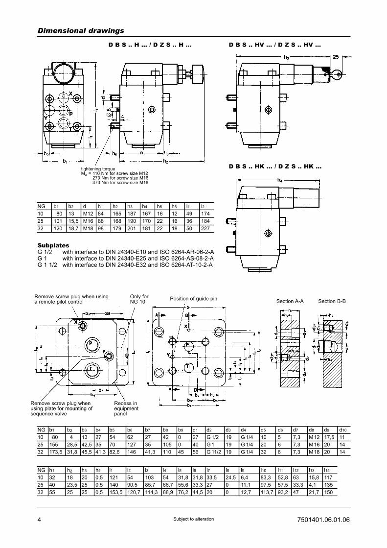
4 7501401.06.01.06Subject to alteration
Dimensional drawings
D B S .. H ... / D Z S .. H ... D B S .. HV ... / D Z S .. HV ...
D B S .. HK ... / D Z S .. HK ...
NG
10
25
32
b1
180
155
173,5
b2
14
28,5
31,8
b3
13
42,5
45,5
b4
27
35
41,3
b5
54
70
82,6
b6
62
127
146
b7
27
35
41,3
b8
42
105
110
b9
0
0
45
d1
27
40
56
d2
G 1/2
G 1
G 11/2
d3
19
19
19
d4
G 1/4
G 1/4
G 1/4
d5
10
20
32
d6
5
6
6
d7
7,3
7,3
7,3
d8
M12
M16
M18
d9
17,5
20
20
d10
11
14
14
NG
10
25
32
h1
32
40
55
h2
18
23,5
25
h3
20
25
25
h4
0,5
0,5
0,5
l1
121
140
153,5
l2
54
90,5
120,7
l3
103
85,7
114,3
l4
54
66,7
88,9
l5
31,8
55,6
76,2
l6
31,8
33,3
44,5
l7
33,5
27
20
l8
24,5
0
0
l9
6,4
11,1
12,7
l10
83,3
97,5
113,7
l11
52,8
57,5
93,2
l12
63
33,3
47
l13
15,8
4,1
21,7
l14
117
135
150
NG
10
25
32
b1
180
101
120
b2
13
15,5
18,7
d
M12
M16
M18
h1
84
88
98
h2
165
168
179
h3
187
190
201
h4
167
170
181
h5
16
22
22
h6
12
16
18
l1
49
36
50
l2
174
184
227
SubplatesG 1/2 with interface to DIN 24340-E10 and ISO 6264-AR-06-2-AG 1 with interface to DIN 24340-E25 and ISO 6264-AS-08-2-AG 1 1/2 with interface to DIN 24340-E32 and ISO 6264-AT-10-2-A
Remove screw plug when usinga remote pilot control
Only forNG 10
Position of guide pinSection A-A Section B-B
Remove screw plug whenusing plate for mounting ofsequence valve
Recess inequipmentpanel
tightening torqueMA = 110 Nm for screw size M12
270 Nm for screw size M16370 Nm for screw size M18
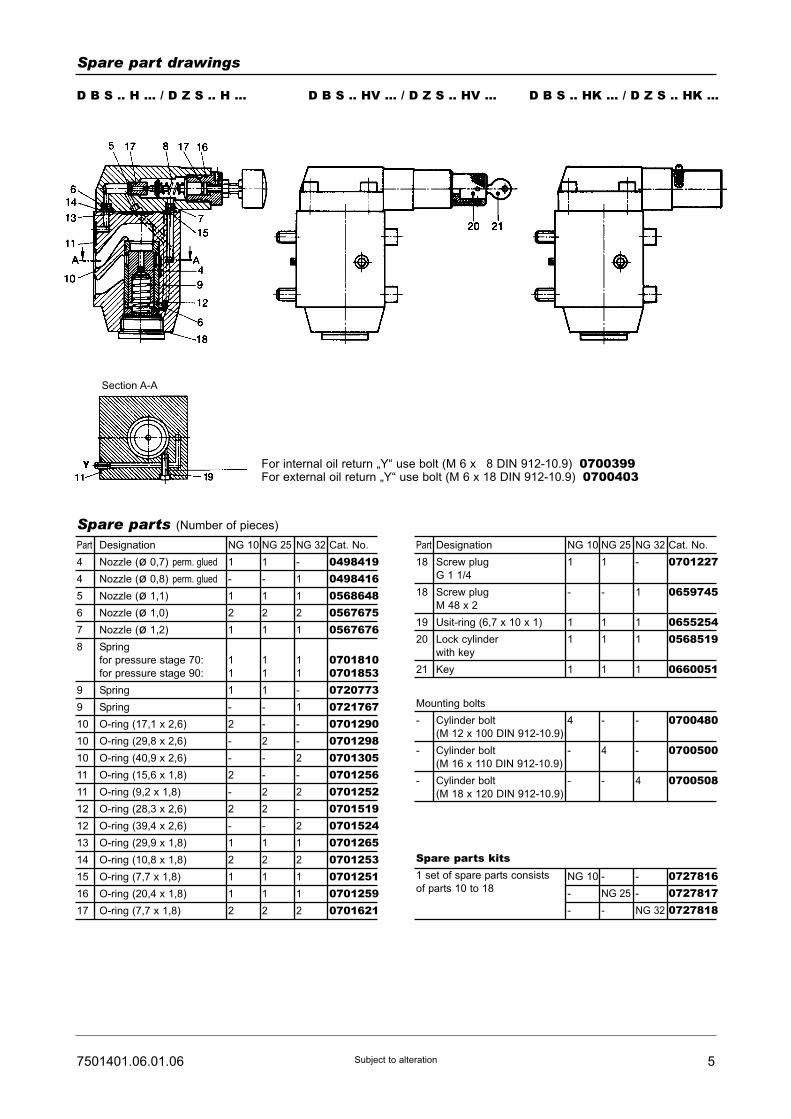
57501401.06.01.06 Subject to alteration
Spare part drawings
D B S .. H ... / D Z S .. H ... D B S .. HV ... / D Z S .. HV ... D B S .. HK ... / D Z S .. HK ...
For internal oil return „Y“ use bolt (M 6 x 18 DIN 912-10.9) 0700399For external oil return „Y“ use bolt (M 6 x 18 DIN 912-10.9) 0700403
Designation
Nozzle (ø 0,7) perm. glued
Nozzle (ø 0,8) perm. glued
Nozzle (ø 1,1)
Nozzle (ø 1,0)
Nozzle (ø 1,2)
Spring
for pressure stage 70:
for pressure stage 90:
Spring
Spring
O-ring (17,1 x 2,6)
O-ring (29,8 x 2,6)
O-ring (40,9 x 2,6)
O-ring (15,6 x 1,8)
O-ring (9,2 x 1,8)
O-ring (28,3 x 2,6)
O-ring (39,4 x 2,6)
O-ring (29,9 x 1,8)
O-ring (10,8 x 1,8)
O-ring (7,7 x 1,8)
O-ring (20,4 x 1,8)
O-ring (7,7 x 1,8)
Part
4
4
5
6
7
8
9
9
10
10
10
11
11
12
12
13
14
15
16
17
Spare parts (Number of pieces)
NG 10
1
-
1
2
1
1
1
1
-
2
-
-
2
-
2
-
1
2
1
1
2
NG 25
1
-
1
2
1
1
1
1
-
-
2
-
-
2
2
-
1
2
1
1
2
NG 32
-
1
1
2
1
1
1
-
1
-
-
2
-
2
-
2
1
2
1
1
2
Cat. No.
04984190498416056864805676750567676
0701810070185307207730721767070129007012980701305070125607012520701519070152407012650701253070125107012590701621
Designation
Screw plug
G 1 1/4
Screw plug
M 48 x 2
Usit-ring (6,7 x 10 x 1)
Lock cylinder
with key
Key
Cylinder bolt
(M 12 x 100 DIN 912-10.9)
Cylinder bolt
(M 16 x 110 DIN 912-10.9)
Cylinder bolt
(M 18 x 120 DIN 912-10.9)
Part
18
18
19
20
21
Mounting bolts
-
-
-
NG 10
1
-
1
1
1
4
-
-
NG 10
-
-
-
NG 25
-
-
-
NG 32
072781607278170727818
NG 25
1
-
1
1
1
-
4
-
NG 32
-
1
1
1
1
-
-
4
Cat. No.
0701227
0659745
06552540568519
0660051
0700480
0700500
0700508
Spare parts kits1 set of spare parts consists
of parts 10 to 18
Section A-A

6 7501401.06.01.06Subject to alteration
Notes:

Pressure Relief ValvesNG 10, 25 and 32indirectly-controlled, interface to DIN 24 340 and ISO 6264
Sequence Valves NG 10, 25 and 32indirectly-controlled, interface of pressure relief valveto DIN 24 340 and ISO 6264
PN [pmax.] = 315 bar 7501401.06.01.06
DesignThe pressure relief valves of Type D B S and thesequence valves of Type D Z S are indirectly-controlledseat valves.
ActuationThe pressure is set manually by means of a rotaryknob. The setting can, if desired, be safeguarded bymeans of locking (E-10-closure) or by means of a leadseal.
MountingThe units are bolted on subplates and sealed byO-rings.
Line connectionSubplate, interface to DIN 24 340 and ISO 6264.
Description (standard units)
Type codePressure relief valveD ... S ... ... ... ... 001 ... O ...
1 2 3 4 5 6 7
SubplateP DB1) ... G ... 001 ... O O
1 2 3
1 Operating B – Pressure relief valvecharacteristics: Z – Sequence valve
2 Nominal size NG: 102532
3 Actuation: H – Manual settingHV – Manual setting, lockableHK – Set-screw with cover
(can be lead sealed)
4 Line connection: G – Subplate, interface toDIN ISO
D – Subplate, interface to DINISO (valve interface not toDIN ISO)
5 Pressure 70 – Up to 100 barsetting range: 90 – Up to 315 bar
6 Engineering 3 – NG 10version: 2 – NG 25
5 – NG 32
7 Sealing material O – PerbunanV – Viton
1 Nominal size NG: 102532
2 Line connection: 4 – G 1/2 NG 106 – G 1 NG 258 – G 1 1/2 NG 32
(Internal toDIN ISO 228/1)
3 Engineering version: 1
1) When using subplate for the installation of sequencevalves, make sure to remove screw plug at port „Y“.
HERION Systemtechnik GmbHUntere Talstraße 65
D-71263 Weil der Stadt-Merklingen
Tel.: +49 (0) 70 33/30 18-0
Fax: +49 (0) 70 33/30 18-10
www.herion-systemtechnik.de
• High flow rating• Insensitive to vibration• Seat design insensitive to dirt
Features

Type designation D B S 10..G. D B S 25..G. D B S 32..G. D Z S 10..G. D Z S 25..G. D Z S 32..G.
General parametersDesignation Pressure relief valve Sequence valve
Symbol
complete
simplified
Design Seat valve, indirectly-controlled
Type of mounting Flange
Line connection Subplate
Mounting position Optional
Flow direction From P to T
Actuation Manual setting
Weight [kg] 6,5 8,6 14,2 6,5 8,6 14,2
Weight of subplate [kg] 2 4,7 17,5 2 4,7 17,5
Ambienttemperature range ϑu [°C] –20 ... +50
Nominal size NG 10 25 32 10 25 32
Hydraulic parametersOperating pressure range pe [bar] ... 315
Adjustable pressure pv [bar] pv min.: see characteristic curverange pv max.: pressure stage 70: ... 100
pressure stage 90: ... 315
Pressure fluid temperature ϑm max. [°C] +70
Viscosity range ν [mm2/s] 12 ... 500
Flow Q [l/min] See characteristic curves
Control oil QSt [l/min] 0,5 See characteristic curve QSt
2 7501401.06.01.06Subject to alteration
Parameters according to VDI 3276
Characteristic curves
(Only for sequence valves)
Values for pv min. refer to external drain of control oil, e.g.when using a remote pilot control and pressure at T = 0 bar.
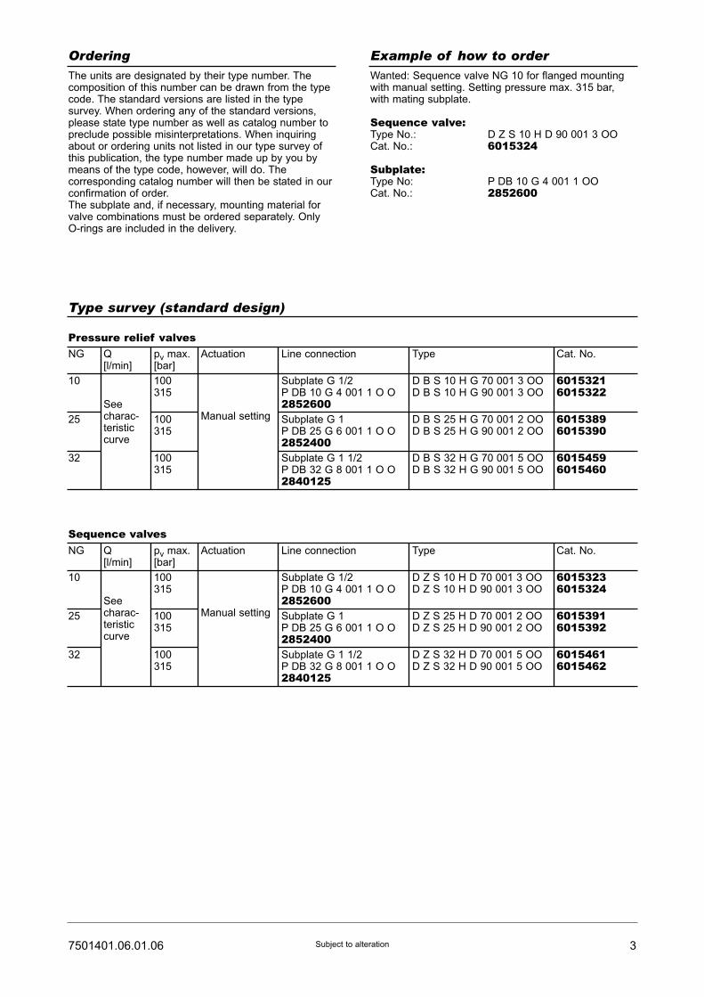
37501401.06.01.06 Subject to alteration
The units are designated by their type number. Thecomposition of this number can be drawn from the typecode. The standard versions are listed in the typesurvey. When ordering any of the standard versions,please state type number as well as catalog number topreclude possible misinterpretations. When inquiringabout or ordering units not listed in our type survey ofthis publication, the type number made up by you bymeans of the type code, however, will do. Thecorresponding catalog number will then be stated in ourconfirmation of order.The subplate and, if necessary, mounting material forvalve combinations must be ordered separately. OnlyO-rings are included in the delivery.
Wanted: Sequence valve NG 10 for flanged mountingwith manual setting. Setting pressure max. 315 bar,with mating subplate.
Sequence valve:Type No.: D Z S 10 H D 90 001 3 OOCat. No.: 6015324
Subplate:Type No: P DB 10 G 4 001 1 OOCat. No.: 2852600
Ordering
Type survey (standard design)
Example of how to order
NG
10
25
32
Q[l/min]
Seecharac-teristiccurve
pv max.[bar]
100315
100315
100315
Actuation
Manual setting
Line connection
Subplate G 1/2P DB 10 G 4 001 1 O O2852600Subplate G 1P DB 25 G 6 001 1 O O2852400Subplate G 1 1/2P DB 32 G 8 001 1 O O2840125
Type
D B S 10 H G 70 001 3 OOD B S 10 H G 90 001 3 OO
D B S 25 H G 70 001 2 OOD B S 25 H G 90 001 2 OO
D B S 32 H G 70 001 5 OOD B S 32 H G 90 001 5 OO
Cat. No.
60153216015322
60153896015390
60154596015460
NG
10
25
32
Q[l/min]
Seecharac-teristiccurve
pv max.[bar]
100315
100315
100315
Actuation
Manual setting
Line connection
Subplate G 1/2P DB 10 G 4 001 1 O O2852600Subplate G 1P DB 25 G 6 001 1 O O2852400Subplate G 1 1/2P DB 32 G 8 001 1 O O2840125
Type
D Z S 10 H D 70 001 3 OOD Z S 10 H D 90 001 3 OO
D Z S 25 H D 70 001 2 OOD Z S 25 H D 90 001 2 OO
D Z S 32 H D 70 001 5 OOD Z S 32 H D 90 001 5 OO
Cat. No.
60153236015324
60153916015392
60154616015462
Pressure relief valves
Sequence valves

4 7501401.06.01.06Subject to alteration
Dimensional drawings
D B S .. H ... / D Z S .. H ... D B S .. HV ... / D Z S .. HV ...
D B S .. HK ... / D Z S .. HK ...
NG
10
25
32
b1
180
155
173,5
b2
14
28,5
31,8
b3
13
42,5
45,5
b4
27
35
41,3
b5
54
70
82,6
b6
62
127
146
b7
27
35
41,3
b8
42
105
110
b9
0
0
45
d1
27
40
56
d2
G 1/2
G 1
G 11/2
d3
19
19
19
d4
G 1/4
G 1/4
G 1/4
d5
10
20
32
d6
5
6
6
d7
7,3
7,3
7,3
d8
M12
M16
M18
d9
17,5
20
20
d10
11
14
14
NG
10
25
32
h1
32
40
55
h2
18
23,5
25
h3
20
25
25
h4
0,5
0,5
0,5
l1
121
140
153,5
l2
54
90,5
120,7
l3
103
85,7
114,3
l4
54
66,7
88,9
l5
31,8
55,6
76,2
l6
31,8
33,3
44,5
l7
33,5
27
20
l8
24,5
0
0
l9
6,4
11,1
12,7
l10
83,3
97,5
113,7
l11
52,8
57,5
93,2
l12
63
33,3
47
l13
15,8
4,1
21,7
l14
117
135
150
NG
10
25
32
b1
180
101
120
b2
13
15,5
18,7
d
M12
M16
M18
h1
84
88
98
h2
165
168
179
h3
187
190
201
h4
167
170
181
h5
16
22
22
h6
12
16
18
l1
49
36
50
l2
174
184
227
SubplatesG 1/2 with interface to DIN 24340-E10 and ISO 6264-AR-06-2-AG 1 with interface to DIN 24340-E25 and ISO 6264-AS-08-2-AG 1 1/2 with interface to DIN 24340-E32 and ISO 6264-AT-10-2-A
Remove screw plug when usinga remote pilot control
Only forNG 10
Position of guide pinSection A-A Section B-B
Remove screw plug whenusing plate for mounting ofsequence valve
Recess inequipmentpanel
tightening torqueMA = 110 Nm for screw size M12
270 Nm for screw size M16370 Nm for screw size M18

57501401.06.01.06 Subject to alteration
Spare part drawings
D B S .. H ... / D Z S .. H ... D B S .. HV ... / D Z S .. HV ... D B S .. HK ... / D Z S .. HK ...
For internal oil return „Y“ use bolt (M 6 x 18 DIN 912-10.9) 0700399For external oil return „Y“ use bolt (M 6 x 18 DIN 912-10.9) 0700403
Designation
Nozzle (ø 0,7) perm. glued
Nozzle (ø 0,8) perm. glued
Nozzle (ø 1,1)
Nozzle (ø 1,0)
Nozzle (ø 1,2)
Spring
for pressure stage 70:
for pressure stage 90:
Spring
Spring
O-ring (17,1 x 2,6)
O-ring (29,8 x 2,6)
O-ring (40,9 x 2,6)
O-ring (15,6 x 1,8)
O-ring (9,2 x 1,8)
O-ring (28,3 x 2,6)
O-ring (39,4 x 2,6)
O-ring (29,9 x 1,8)
O-ring (10,8 x 1,8)
O-ring (7,7 x 1,8)
O-ring (20,4 x 1,8)
O-ring (7,7 x 1,8)
Part
4
4
5
6
7
8
9
9
10
10
10
11
11
12
12
13
14
15
16
17
Spare parts (Number of pieces)
NG 10
1
-
1
2
1
1
1
1
-
2
-
-
2
-
2
-
1
2
1
1
2
NG 25
1
-
1
2
1
1
1
1
-
-
2
-
-
2
2
-
1
2
1
1
2
NG 32
-
1
1
2
1
1
1
-
1
-
-
2
-
2
-
2
1
2
1
1
2
Cat. No.
04984190498416056864805676750567676
0701810070185307207730721767070129007012980701305070125607012520701519070152407012650701253070125107012590701621
Designation
Screw plug
G 1 1/4
Screw plug
M 48 x 2
Usit-ring (6,7 x 10 x 1)
Lock cylinder
with key
Key
Cylinder bolt
(M 12 x 100 DIN 912-10.9)
Cylinder bolt
(M 16 x 110 DIN 912-10.9)
Cylinder bolt
(M 18 x 120 DIN 912-10.9)
Part
18
18
19
20
21
Mounting bolts
-
-
-
NG 10
1
-
1
1
1
4
-
-
NG 10
-
-
-
NG 25
-
-
-
NG 32
072781607278170727818
NG 25
1
-
1
1
1
-
4
-
NG 32
-
1
1
1
1
-
-
4
Cat. No.
0701227
0659745
06552540568519
0660051
0700480
0700500
0700508
Spare parts kits1 set of spare parts consists
of parts 10 to 18
Section A-A

6 7501401.06.01.06Subject to alteration
Notes:
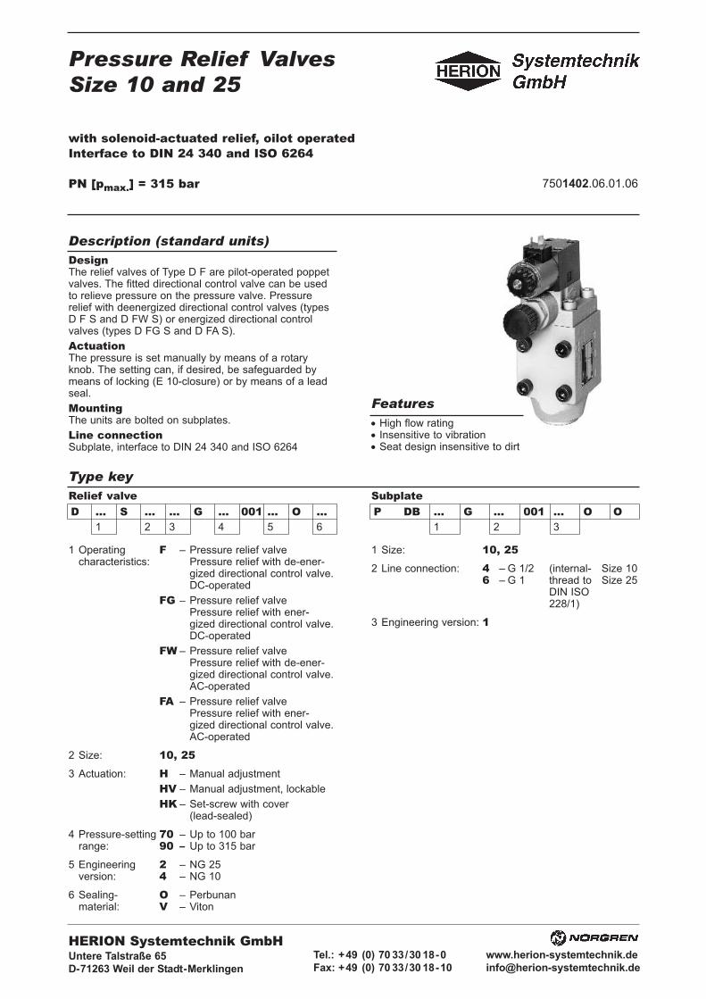
Pressure Relief ValvesSize 10 and 25
with solenoid-actuated relief, oilot operatedInterface to DIN 24 340 and ISO 6264
PN [pmax.] = 315 bar 7501402.06.01.06
DesignThe relief valves of Type D F are pilot-operated poppetvalves. The fitted directional control valve can be usedto relieve pressure on the pressure valve. Pressurerelief with deenergized directional control valves (typesD F S and D FW S) or energized directional controlvalves (types D FG S and D FA S).
ActuationThe pressure is set manually by means of a rotaryknob. The setting can, if desired, be safeguarded bymeans of locking (E 10-closure) or by means of a leadseal.
MountingThe units are bolted on subplates.
Line connectionSubplate, interface to DIN 24 340 and ISO 6264
• High flow rating• Insensitive to vibration• Seat design insensitive to dirt
Description (standard units)
Features
Type keyRelief valveD ... S ... ... G ... 001 ... O ...
1 2 3 4 5 6
SubplateP DB ... G ... 001 ... O O
1 2 3
1 Operating F – Pressure relief valvecharacteristics: Pressure relief with de-ener-
gized directional control valve.DC-operated
FG – Pressure relief valvePressure relief with ener-gized directional control valve.DC-operated
FW – Pressure relief valvePressure relief with de-ener-gized directional control valve.AC-operated
FA – Pressure relief valvePressure relief with ener-gized directional control valve.AC-operated
2 Size: 10, 253 Actuation: H – Manual adjustment
HV – Manual adjustment, lockable
HK – Set-screw with cover(lead-sealed)
4 Pressure-setting 70 – Up to 100 barrange: 90 – Up to 315 bar
5 Engineering 2 – NG 25version: 4 – NG 10
6 Sealing- O – Perbunanmaterial: V – Viton
1 Size: 10, 252 Line connection: 4 – G 1/2 (internal- Size 10
6 – G 1 thread to Size 25DIN ISO228/1)
3 Engineering version: 1
HERION Systemtechnik GmbHUntere Talstraße 65
D-71263 Weil der Stadt-Merklingen
Tel.: +49 (0) 70 33/30 18-0
Fax: +49 (0) 70 33/30 18-10
www.herion-systemtechnik.de

Type designation D F S ... D FG S ... D FW S ... D FA S ...(pressure reliefvalve)
Type designation S 6 VH 10 G 088 001 6 O V S 6 VH 10 G 159 001 6 O V S 6 VG 11 G 088 001 6 O V S 6 VG 11 G 159 001 6 O V(directional controlvalve) Cat. No. 5204101.7234 5204097.7234 5204729.7234 5201083.7234Designation Directional control valve
Design Spool valve
Type of mounting Flange
Line connection Subplate
Ambient-temperature-range ϑu [°C] From -20 ... +50
Size 6
Type designation D F S 10 ... G ... D F S 25 ... G ...
General parametersDesignation Pressure relief valve
Symbol D F S ..., D FW S ... D FG S ..., D FA S ...
complete
simplified
Design Poppet valve, pilot operated
Type of mounting Flange
Line connection Subplate
Mounting position Optional
Flow direction From P to T
Actuation Manual setting, pressure relief via directional control valve
Weight [kg] 6 10
Weight of subplate [kg] 2 14.7
Ambient temperaturerange ϑu [°C] From –20 ... +50
Size 10 25
Hydraulic parametersOperating pressure range pe [bar] ... 315
Adjustable pressure range pv [bar] pv min.: See characteristic curvepv max.: Pressure stage 70: ... 100
Pressure stage 90: ... 315
Pressure fluid temperature ϑm max. [°C] +70
Viscosity range ν [mm2/s] From 12 ... 500
Flow Q [l/min] See characteristic curves
Control oil QSt [l/min] 0.5
2 7501402.06.01.06Subject to alteration
Parameters according to VDI 3276
Parameters of fitted directional control valve

37501402.06.01.06 Subject to alteration
Electrical parameters
Characteristic curves - Pressure valves
Response times te [ms] 30 to 50 30 to 40ta [ms] 10 to 50 30 to 40
Number of switchings/hour 15000
Rated voltage UN [V] 24 230 V 40 ... 60 Hz±10% ±10%
Other voltages upon request
Current draw DC P 20 [W] 32 -AC P 20 [VA] - 39
Duty cycle EDrel. [%] 100
Degree of protection for solenoids IP 00, with connector IP 65and electrical connection to DIN 40050
Electrical connection Connector to DIN 43650 on solenoid
Values for pv min. apply to external return of control oil, e.g. when a remote pilot control is being used and pressure at T = 0 bar
The units are designated by their type number. Thecomposition of this number can be drawn from the typecode. The standard versions are listed in the typesurvey. When ordering any of the standard versions,please state type number as well as catalog number topreclude possible misinterpretations.When inquiring about or ordering units not listed in ourtype survey of this publication, the type number madeup by you by means of the type code, however, will do.The corresponding catalog number will then be statedin our confirmation of order. Units with flanged connec-tion are delivered complete with fixing bolts andO-rings. The subplate must be ordered separately.
Wanted: Pressure relief valve with solenoid-actuatedrelief size 10, flanged with manual adjustment.Pressure setting up to max. 315 bar, with matchingsubplate.
Pressure relief valve:Type No.: D F S 10 H G 90 001 4 O OCat No.: 6015326.7234.02400Voltage: 24 VDC
Subplate:Type No.: P DB 10 G 4 001 1 O OCat No.: 2852600
Ordering
Type survey (standard designs)
Example of order
Size
10
25
Q[l/min]
Seecharac-teristiccurve
pv max.[bar]
100315
100315
Actuation
Manual setting
Line connection
Subplate G 1/2P DB 10 G 4 001 1 O O2852600Subplate G 1P DB 25 G 6 001 1 O O2852400
Type
D F S 10 H G 70 001 4 OOD F S 10 H G 90 001 4 OO
D F S 25 H G 70 001 2 OOD F S 25 H G 90 001 2 OO
Cat No.
6015325.72346015326.7234
6015393.72346015394.7234
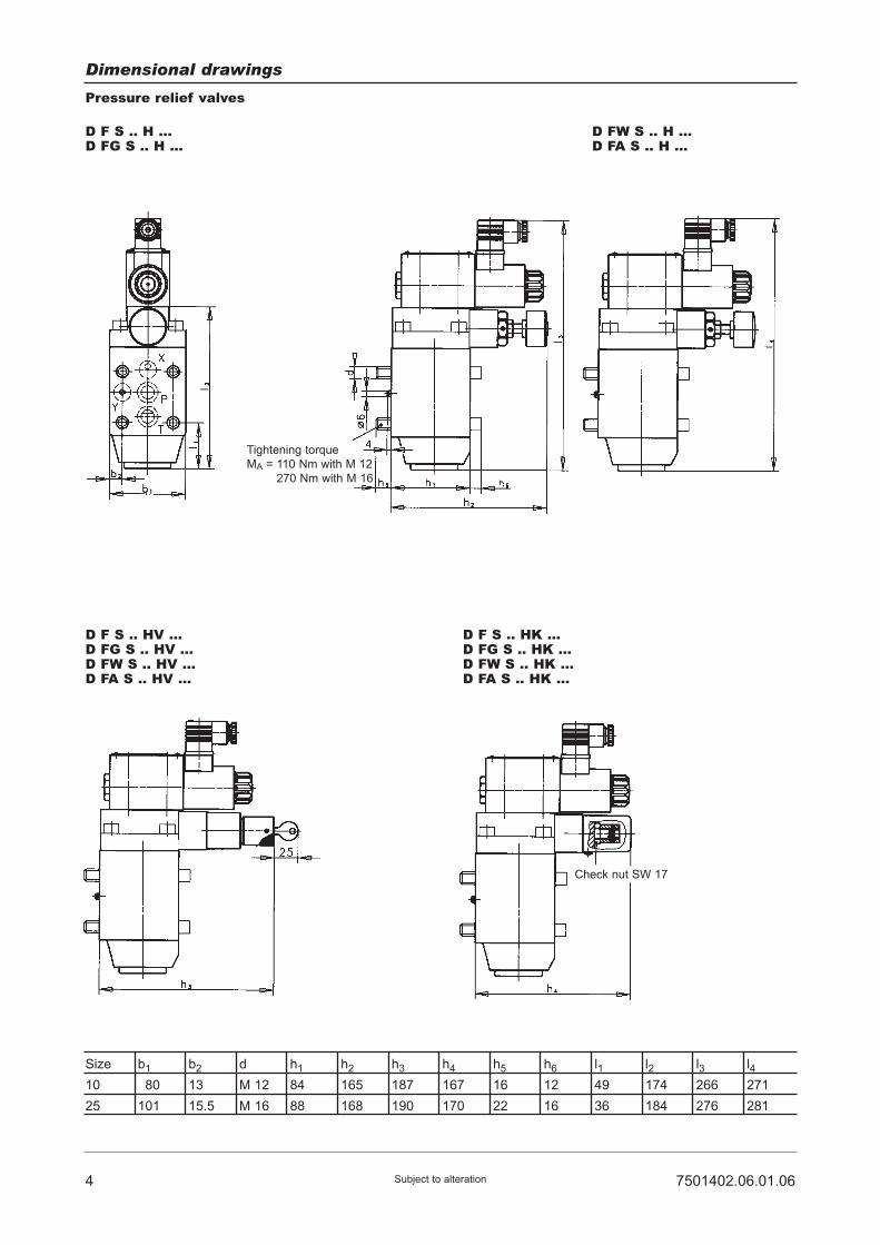
4 7501402.06.01.06Subject to alteration
Dimensional drawings
Pressure relief valves
D F S .. H ...D FG S .. H ...
D FW S .. H ...D FA S .. H ...
D F S .. HV ...D FG S .. HV ...D FW S .. HV ...D FA S .. HV ...
D F S .. HK ...D FG S .. HK ...D FW S .. HK ...D FA S .. HK ...
Size
10
25
b1
180
101
b2
13
15.5
d
M 12
M 16
h1
84
88
h2
165
168
h3
187
190
h4
167
170
h5
16
22
h6
12
16
l1
49
36
l2
174
184
l3
266
276
l4
271
281
Tightening torque
MA = 110 Nm with M 12
270 Nm with M 16
Check nut SW 17

Designation
Nozzle (dia. 0.7)eingeklebt
Nozzle (dia. 1.1)
Nozzle (dia. 1.0)
Nozzle (dia. 1.2)
Spring Pressure stage 70:Pressure stage 90:
Spring
O-ring (17.1 x 2.6)
O-ring (29.8 x 2.6)
O-ring (15.6 x 1.8)
O-ring (9.2 x 1.8)
O-ring (28.3 x 2.6)
O-ring (29.9 x 1.8)
O-ring (10.8 x 1.8)
O-ring (7.7 x 1.8)
O-ring (20.4 x 1.8)
O-ring (7.7 x 1.8)
Plug G 1 1/4
Usit-ring (6.7 x 10 x 1)
Lock cylinder with key
Key
Bolt (M 12 x 100 DIN 912-10.9)
Bolt (M 16 x 110 DIN 912-10.9)
Part
4
5
6
7
8
9
10
10
11
11
12
13
14
15
16
17
18
19
20
21
Mounting bolts
-
-
57501402.06.01.06 Subject to alteration
Spare partsSize 10
1
1
2
1
11
1
2
-
2
-
2
1
2
1
1
1
1
1
1
1
4
-
Size 25
1
1
2
1
11
1
-
2
-
2
2
1
2
1
1
1
1
1
1
1
-
4
Cat. No.
049841905686480567675056767607018100701853072079107012900701298070125607012520701297070126507012530701251070125907014840701227065525405685190660051
07004800700500
1 set of spare parts consists of parts 10 to 18.
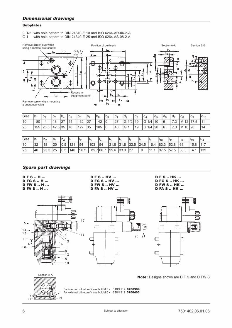
6 7501402.06.01.06Subject to alteration
Dimensional drawings
Subplates
G 1/2 with hole pattern to DIN 24340-E 10 and ISO 6264-AR-06-2-AG 1 with hole pattern to DIN 24340-E 25 and ISO 6264-AS-08-2-A
Size
10
25
b1
180
155
b2
14
28.5
b3
13
42.5
b4
27
35
b5
54
70
b6
162
127
b7
27
35
b8
142
105
b9
0
0
d1
27
40
d2
G 1/2
G 1
d3
19
19
d4
G 1/4
G 1/4
d5
10
20
d6
5
6
d7
7.3
7.3
d8
M 12
M 16
d9
17.5
20
d10
11
14
Size
10
25
h1
32
40
h2
18
23.5
h3
20
25
h4
0.5
0.5
l1
121
140
l2
54
90.5
l3
103
185.7
l4
54
66.7
l5
31.8
55.6
l6
31.8
33.3
l7
33.5
27
l8
24.5
20
l9
16.4
11.1
l10
83.3
97.5
l11
52.8
57.5
l12
63
33.3
l13
15.8
14.1
l14
117
135
Spare part drawings
D F S .. H ...D FG S .. H ...D FW S .. H ...D FA S .. H ...
D F S .. HV ...D FG S .. HV ...D FW S .. HV ...D FA S .. HV ...
D F S .. HK ...D FG S .. HK ...D FW S .. HK ...D FA S .. HK ...
Note: Designs shown are D F S and D FW S
Remove screw plug whenusing a remote pilot control
Only forsize 10
Recess inequipment panel
Position of guide pin Section A-A Section B-B
Section A-A
For internal oil return Y use bolt M 6 x 18 DIN 912 0700399For external oil return Y use bolt M 6 x 18 DIN 912 0700403
Remove screw when mountinga sequence valve

Pressure Relief ValvesSize 10 and 25
with solenoid-actuated relief, oilot operatedInterface to DIN 24 340 and ISO 6264
PN [pmax.] = 315 bar 7501402.06.01.06
DesignThe relief valves of Type D F are pilot-operated poppetvalves. The fitted directional control valve can be usedto relieve pressure on the pressure valve. Pressurerelief with deenergized directional control valves (typesD F S and D FW S) or energized directional controlvalves (types D FG S and D FA S).
ActuationThe pressure is set manually by means of a rotaryknob. The setting can, if desired, be safeguarded bymeans of locking (E 10-closure) or by means of a leadseal.
MountingThe units are bolted on subplates.
Line connectionSubplate, interface to DIN 24 340 and ISO 6264
• High flow rating• Insensitive to vibration• Seat design insensitive to dirt
Description (standard units)
Features
Type keyRelief valveD ... S ... ... G ... 001 ... O ...
1 2 3 4 5 6
SubplateP DB ... G ... 001 ... O O
1 2 3
1 Operating F – Pressure relief valvecharacteristics: Pressure relief with de-ener-
gized directional control valve.DC-operated
FG – Pressure relief valvePressure relief with ener-gized directional control valve.DC-operated
FW – Pressure relief valvePressure relief with de-ener-gized directional control valve.AC-operated
FA – Pressure relief valvePressure relief with ener-gized directional control valve.AC-operated
2 Size: 10, 253 Actuation: H – Manual adjustment
HV – Manual adjustment, lockable
HK – Set-screw with cover(lead-sealed)
4 Pressure-setting 70 – Up to 100 barrange: 90 – Up to 315 bar
5 Engineering 2 – NG 25version: 4 – NG 10
6 Sealing- O – Perbunanmaterial: V – Viton
1 Size: 10, 252 Line connection: 4 – G 1/2 (internal- Size 10
6 – G 1 thread to Size 25DIN ISO228/1)
3 Engineering version: 1
HERION Systemtechnik GmbHUntere Talstraße 65
D-71263 Weil der Stadt-Merklingen
Tel.: +49 (0) 70 33/30 18-0
Fax: +49 (0) 70 33/30 18-10
www.herion-systemtechnik.de
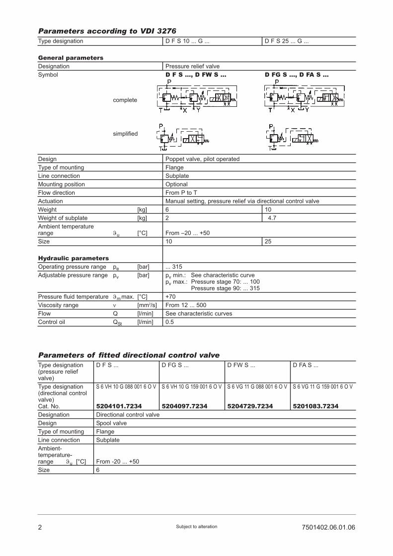
Type designation D F S ... D FG S ... D FW S ... D FA S ...(pressure reliefvalve)
Type designation S 6 VH 10 G 088 001 6 O V S 6 VH 10 G 159 001 6 O V S 6 VG 11 G 088 001 6 O V S 6 VG 11 G 159 001 6 O V(directional controlvalve) Cat. No. 5204101.7234 5204097.7234 5204729.7234 5201083.7234Designation Directional control valve
Design Spool valve
Type of mounting Flange
Line connection Subplate
Ambient-temperature-range ϑu [°C] From -20 ... +50
Size 6
Type designation D F S 10 ... G ... D F S 25 ... G ...
General parametersDesignation Pressure relief valve
Symbol D F S ..., D FW S ... D FG S ..., D FA S ...
complete
simplified
Design Poppet valve, pilot operated
Type of mounting Flange
Line connection Subplate
Mounting position Optional
Flow direction From P to T
Actuation Manual setting, pressure relief via directional control valve
Weight [kg] 6 10
Weight of subplate [kg] 2 14.7
Ambient temperaturerange ϑu [°C] From –20 ... +50
Size 10 25
Hydraulic parametersOperating pressure range pe [bar] ... 315
Adjustable pressure range pv [bar] pv min.: See characteristic curvepv max.: Pressure stage 70: ... 100
Pressure stage 90: ... 315
Pressure fluid temperature ϑm max. [°C] +70
Viscosity range ν [mm2/s] From 12 ... 500
Flow Q [l/min] See characteristic curves
Control oil QSt [l/min] 0.5
2 7501402.06.01.06Subject to alteration
Parameters according to VDI 3276
Parameters of fitted directional control valve
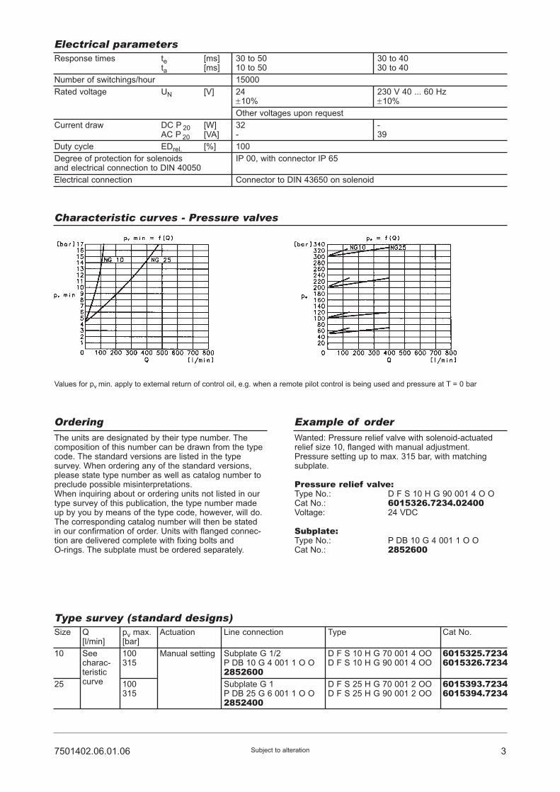
37501402.06.01.06 Subject to alteration
Electrical parameters
Characteristic curves - Pressure valves
Response times te [ms] 30 to 50 30 to 40ta [ms] 10 to 50 30 to 40
Number of switchings/hour 15000
Rated voltage UN [V] 24 230 V 40 ... 60 Hz±10% ±10%
Other voltages upon request
Current draw DC P 20 [W] 32 -AC P 20 [VA] - 39
Duty cycle EDrel. [%] 100
Degree of protection for solenoids IP 00, with connector IP 65and electrical connection to DIN 40050
Electrical connection Connector to DIN 43650 on solenoid
Values for pv min. apply to external return of control oil, e.g. when a remote pilot control is being used and pressure at T = 0 bar
The units are designated by their type number. Thecomposition of this number can be drawn from the typecode. The standard versions are listed in the typesurvey. When ordering any of the standard versions,please state type number as well as catalog number topreclude possible misinterpretations.When inquiring about or ordering units not listed in ourtype survey of this publication, the type number madeup by you by means of the type code, however, will do.The corresponding catalog number will then be statedin our confirmation of order. Units with flanged connec-tion are delivered complete with fixing bolts andO-rings. The subplate must be ordered separately.
Wanted: Pressure relief valve with solenoid-actuatedrelief size 10, flanged with manual adjustment.Pressure setting up to max. 315 bar, with matchingsubplate.
Pressure relief valve:Type No.: D F S 10 H G 90 001 4 O OCat No.: 6015326.7234.02400Voltage: 24 VDC
Subplate:Type No.: P DB 10 G 4 001 1 O OCat No.: 2852600
Ordering
Type survey (standard designs)
Example of order
Size
10
25
Q[l/min]
Seecharac-teristiccurve
pv max.[bar]
100315
100315
Actuation
Manual setting
Line connection
Subplate G 1/2P DB 10 G 4 001 1 O O2852600Subplate G 1P DB 25 G 6 001 1 O O2852400
Type
D F S 10 H G 70 001 4 OOD F S 10 H G 90 001 4 OO
D F S 25 H G 70 001 2 OOD F S 25 H G 90 001 2 OO
Cat No.
6015325.72346015326.7234
6015393.72346015394.7234

4 7501402.06.01.06Subject to alteration
Dimensional drawings
Pressure relief valves
D F S .. H ...D FG S .. H ...
D FW S .. H ...D FA S .. H ...
D F S .. HV ...D FG S .. HV ...D FW S .. HV ...D FA S .. HV ...
D F S .. HK ...D FG S .. HK ...D FW S .. HK ...D FA S .. HK ...
Size
10
25
b1
180
101
b2
13
15.5
d
M 12
M 16
h1
84
88
h2
165
168
h3
187
190
h4
167
170
h5
16
22
h6
12
16
l1
49
36
l2
174
184
l3
266
276
l4
271
281
Tightening torque
MA = 110 Nm with M 12
270 Nm with M 16
Check nut SW 17
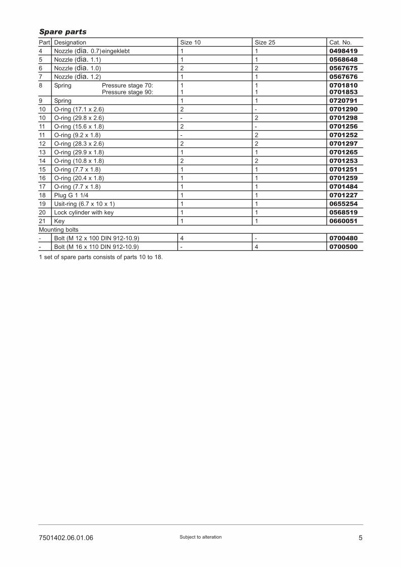
Designation
Nozzle (dia. 0.7)eingeklebt
Nozzle (dia. 1.1)
Nozzle (dia. 1.0)
Nozzle (dia. 1.2)
Spring Pressure stage 70:Pressure stage 90:
Spring
O-ring (17.1 x 2.6)
O-ring (29.8 x 2.6)
O-ring (15.6 x 1.8)
O-ring (9.2 x 1.8)
O-ring (28.3 x 2.6)
O-ring (29.9 x 1.8)
O-ring (10.8 x 1.8)
O-ring (7.7 x 1.8)
O-ring (20.4 x 1.8)
O-ring (7.7 x 1.8)
Plug G 1 1/4
Usit-ring (6.7 x 10 x 1)
Lock cylinder with key
Key
Bolt (M 12 x 100 DIN 912-10.9)
Bolt (M 16 x 110 DIN 912-10.9)
Part
4
5
6
7
8
9
10
10
11
11
12
13
14
15
16
17
18
19
20
21
Mounting bolts
-
-
57501402.06.01.06 Subject to alteration
Spare partsSize 10
1
1
2
1
11
1
2
-
2
-
2
1
2
1
1
1
1
1
1
1
4
-
Size 25
1
1
2
1
11
1
-
2
-
2
2
1
2
1
1
1
1
1
1
1
-
4
Cat. No.
049841905686480567675056767607018100701853072079107012900701298070125607012520701297070126507012530701251070125907014840701227065525405685190660051
07004800700500
1 set of spare parts consists of parts 10 to 18.

6 7501402.06.01.06Subject to alteration
Dimensional drawings
Subplates
G 1/2 with hole pattern to DIN 24340-E 10 and ISO 6264-AR-06-2-AG 1 with hole pattern to DIN 24340-E 25 and ISO 6264-AS-08-2-A
Size
10
25
b1
180
155
b2
14
28.5
b3
13
42.5
b4
27
35
b5
54
70
b6
162
127
b7
27
35
b8
142
105
b9
0
0
d1
27
40
d2
G 1/2
G 1
d3
19
19
d4
G 1/4
G 1/4
d5
10
20
d6
5
6
d7
7.3
7.3
d8
M 12
M 16
d9
17.5
20
d10
11
14
Size
10
25
h1
32
40
h2
18
23.5
h3
20
25
h4
0.5
0.5
l1
121
140
l2
54
90.5
l3
103
185.7
l4
54
66.7
l5
31.8
55.6
l6
31.8
33.3
l7
33.5
27
l8
24.5
20
l9
16.4
11.1
l10
83.3
97.5
l11
52.8
57.5
l12
63
33.3
l13
15.8
14.1
l14
117
135
Spare part drawings
D F S .. H ...D FG S .. H ...D FW S .. H ...D FA S .. H ...
D F S .. HV ...D FG S .. HV ...D FW S .. HV ...D FA S .. HV ...
D F S .. HK ...D FG S .. HK ...D FW S .. HK ...D FA S .. HK ...
Note: Designs shown are D F S and D FW S
Remove screw plug whenusing a remote pilot control
Only forsize 10
Recess inequipment panel
Position of guide pin Section A-A Section B-B
Section A-A
For internal oil return Y use bolt M 6 x 18 DIN 912 0700399For external oil return Y use bolt M 6 x 18 DIN 912 0700403
Remove screw when mountinga sequence valve

Accumulator safety valvesSize 6 and 10Directly-controlledwith TÜV type approval according to DGR 97/23/EG, cartridge-type
PN [pmax.] = 10 to 350 bar 7501406.06.01.06
DesignThe accumulator safety valves of Type D B C aredirectly-operated seat valves, and have TÜV typeapproval. The maximum pressure is limited by a lead-sealed stop. The setting of the maximum pressure iscarried out in the factory. To prevent unauthorizedresetting to another pressure, the cover hood issecured by a lead seal. Accumulator safety valves areused to protect the hydraulic accumulator againstexcessive pressure. The accumulator safety valveshould be chosen such that the pump delivery is equalto or less than the permissible blowoff of the particularvalve, taking into account the operating pressure.
• High blowoff• Tightly-closing seat valve
Description (standard units)
Features
Type keyAccumulator safety valveD B C ... HK E ... 017 ... O ...
1 2 3 4
1 Size: 16 see table10
2 Operating-pressure: 10 – 110 bar61 – 163 bar70 – 100 bar75 – 150 bar80 – 210 bar85 – 250 bar89 – 300 bar90 – 315 bar
3 Engineering version: 14 Sealing material: O – Perbunan
HERION Systemtechnik GmbHUntere Talstraße 65
D-71263 Weil der Stadt-Merklingen
Tel.: +49 (0) 70 33/30 18-0
Fax: +49 (0) 70 33/30 18-10
www.herion-systemtechnik.de
When ordering, please state type No. along withcatalog No. listed in the type survey overleaf.
Wanted: Accumulator safety valve size 6, pressuresetting 210 bar, blowoff max. 61 l/min.
Order: Accumulator safety valve,Type No.: D B C 6 HK E 80 017 1 O OCat. No.: 6014339
Ordering
Example of how to order
Type designation D B C 6 .. D B C 10 ..
General parametersDesignation Accumulator safety valve
Symbol
Design Seat valve, directly controlled
Mounting position Optional
Flow direction From P to T
Ambient temperaturerange ϑu max. [°C] –10 bis +50
Size ν NG 6 10
Hydraulic parametersOperating pressurerange pe [bar] Pressure stage 10: 110
Pressure stage 61: 163Pressure stage 70: 100Pressure stage 75: 150Pressure stage 80: 210Pressure stage 81: 235Pressure stage 85: 250Pressure stage 89: 300Pressure stage 90: 315Pressure stage 91: 350
Pressure fluidtemperature ϑm max. [°C] +70
Viscosity range ν [mm2/s] From 12 to 500
Blowoff G [l/min] See type survey
Parameters according to VDI 3276
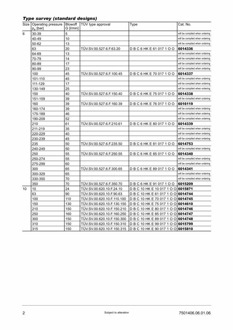
2 7501406.06.01.06Subject to alteration
Type survey (standard designs)Size Operating pressure
pe [bar]BlowoffG [l/min]
TÜV type approval Type Cat. No.
6
10
30-39
40-49
50-62
63
64-69
70-79
80-89
90-99
100
101-110
111-129
130-149
150
151-159
160
160-174
175-189
190-209
210
211-219
220-229
230-239
235
240-249
250
250-274
275-299
300
300-329
330-350
350
10
63
100
150
210
250
300
310
315
5
10
13
20
13
14
17
23
45
45
17
25
40
39
39
39
46
52
61
35
40
45
50
50
55
55
60
65
65
70
70
24
90
110
130
150
160
150
150
150
TÜV.SV.00.527.6.F.63.20
TÜV.SV.00.527.6.F.100.45
TÜV.SV.00.527.6.F.150.40
TÜV.SV.00.527.6.F.160.39
TÜV.SV.00.527.6.F.210.61
TÜV.SV.00.527.6.F.235.50
TÜV.SV.00.527.6.F.250.55
TÜV.SV.00.527.6.F.300.65
TÜV.SV.00.527.6.F.350.70
TÜV.SV.00.620.10.F.24.10
TÜV.SV.00.620.10.F.90.63
TÜV.SV.00.620.10.F.110.100
TÜV.SV.00.620.10.F.130.150
TÜV.SV.00.620.10.F.150.210
TÜV.SV.00.620.10.F.160.250
TÜV.SV.00.620.10.F.150.300
TÜV.SV.00.620.10.F.150.310
TÜV.SV.00.620.10.F.150.315
D B C 6 HK E 61 017 1 O O
D B C 6 HK E 70 017 1 O O
D B C 6 HK E 75 017 1 O O
D B C 6 HK E 76 017 1 O O
D B C 6 HK E 80 017 1 O O
D B C 6 HK E 81 017 1 O O
D B C 6 HK E 85 017 1 O O
D B C 6 HK E 89 017 1 O O
D B C 6 HK E 91 017 1 O O
D B C 10 HK E 10 017 1 O O
D B C 10 HK E 61 017 1 O O
D B C 10 HK E 70 017 1 O O
D B C 10 HK E 75 017 1 O O
D B C 10 HK E 80 017 1 O O
D B C 10 HK E 85 017 1 O O
D B C 10 HK E 89 017 1 O O
D B C 10 HK E 99 017 1 O O
D B C 10 HK E 90 017 1 O O
will be compiled when ordering
will be compiled when ordering
will be compiled when ordering
6014336will be compiled when ordering
will be compiled when ordering
will be compiled when ordering
will be compiled when ordering
6014337will be compiled when ordering
will be compiled when ordering
will be compiled when ordering
6014338will be compiled when ordering
6016119will be compiled when ordering
will be compiled when ordering
will be compiled when ordering
6014339will be compiled when ordering
will be compiled when ordering
will be compiled when ordering
6014753will be compiled when ordering
6014340will be compiled when ordering
will be compiled when ordering
6014341will be compiled when ordering
will be compiled when ordering
6015209601587160147446014745601461060147466014747601474860157996015810

37501406.06.01.06 Subject to alteration
Dimensional drawingsPressure valveD B C 6 .. E ..
Receiving boreFor D B C 6 .. E ..
Spare parts drawingsD B C 6 HK ..
D B C 10 HK ..
D B C 10 .. E ..For D B C 10 .. E ..
DesignationPart Qty.
Spare partsCat. No.
Usit-ring (17,4 x 24 x 1,5)
O-ring (20,3 x 2,6)
1
2
1
1
06571210701514
1 Set of spare parts consists of parts 1 and 2.These spare parts are not available separately.
DesignationPart Qty. Cat. No.
Usit-ring (22,7 x 30 x 2)
O-ring (26,7 x 2,6)
1
2
1
1
06590440701518
1 Set of spare parts consists of parts 1 and 2.These spare parts are not available separately.
Lead-sealed
Lead-sealed
Optional
Depth
Optional
Depth

4 7501406.06.01.06Subject to alteration
Notice:
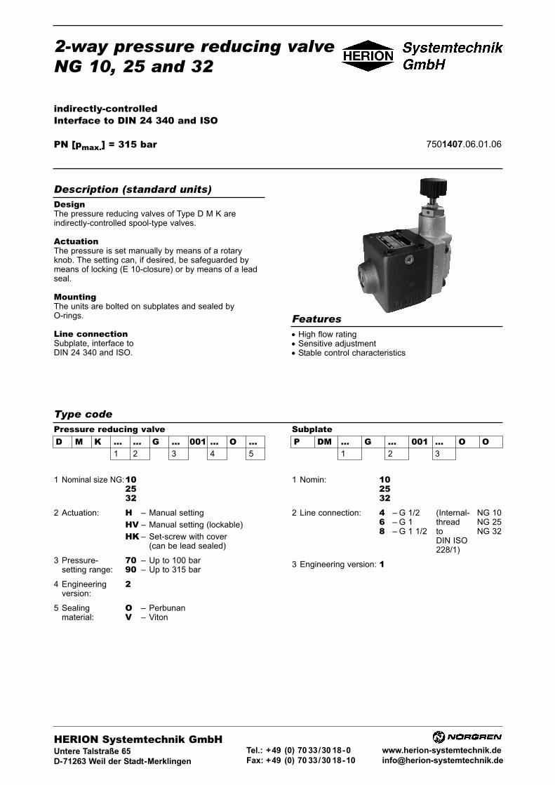
2-way pressure reducing valveNG 10, 25 and 32
indirectly-controlledInterface to DIN 24 340 and ISO
PN [pmax.] = 315 bar 7501407.06.01.06
DesignThe pressure reducing valves of Type D M K areindirectly-controlled spool-type valves.
ActuationThe pressure is set manually by means of a rotaryknob. The setting can, if desired, be safeguarded bymeans of locking (E 10-closure) or by means of a leadseal.
MountingThe units are bolted on subplates and sealed byO-rings.
Line connectionSubplate, interface toDIN 24 340 and ISO.
• High flow rating• Sensitive adjustment• Stable control characteristics
Description (standard units)
Features
Type codePressure reducing valveD M K ... ... G ... 001 ... O ...
1 2 3 4 5
SubplateP DM ... G ... 001 ... O O
1 2 3
1 Nominal size NG:102532
2 Actuation: H – Manual setting
HV – Manual setting (lockable)
HK – Set-screw with cover(can be lead sealed)
3 Pressure- 70 – Up to 100 barsetting range: 90 – Up to 315 bar
4 Engineering 2version:
5 Sealing O – Perbunanmaterial: V – Viton
1 Nomin: 102532
2 Line connection: 4 – G 1/2 (Internal- NG 106 – G 1 thread NG 258 – G 1 1/2 to NG 32
DIN ISO228/1)
3 Engineering version: 1
HERION Systemtechnik GmbHUntere Talstraße 65
D-71263 Weil der Stadt-Merklingen
Tel.: +49 (0) 70 33/30 18-0
Fax: +49 (0) 70 33/30 18-10
www.herion-systemtechnik.de

2 7501407.06.01.06Subject to alteration
Type designation D M K 10..G... D M K 25..G... D M K 32..G...
General parametersDesignation Pressure reducing valve
Symbol
complete
simplified
Design Spool-type valve, indirectly-controlled
Type of mounting Flange
Line connection Subplate
Mounting position Optional
Flow direction From B to A
Actuation Manual setting
Weight of pressure reducing valve [kg] 4,9 8,2 10
Weight of subplate [kg] 1,6 3,7 5,9
Ambienttemperature ϑu [°C] –20 ... +50
Size ν NG 10 25 32
Hydraulic parametersOperating pressure range pe [bar] ... 315
Adjustable pressure range pv [bar] Pressure stage 70: 5 bis 100Pressure stage 90: 5 bis 315
Pressure medium temperature ϑm max. [°C] +70
Viscosity range ν [mm2/s] 12 ... 500
Flow Q [l/min] See characteristic curves
Control oil flow QSt [l/min] 0,5
Parameters according to VDI 3276
Characteristic curves
Note: If flow is from AfB, setting pressure
pv must be higher than the max. return pressure at port B and
corresponding Vp of diagram.
Outlet
pre
ssure
p
(Spool position open)

37501407.06.01.06 Subject to alteration
The units are designated by their type number. Thecomposition of this number can be drawn from the typecode. The standard versions are listed in the typesurvey. When ordering any of the standard versions,please state type number as well as catalog number topreclude possible misinterpretations. When inquiringabout or ordering units not listed in our type survey ofthis publication, the type number made up by you bymeans of the type code, however, will do. Thecorresponding catalog number will then be stated in ourconfirmation of order. Units with flanged connection aredelivered complete with fixing bolts and O-rings. Thesubplate must be ordered separately.
Wanted: Pressure reducing valve NG 10 for flangedmounting with manual setting. Setting pressure max.315 bar, with mating subplate.
Pressure reducing valve:Type-No.: D M K 10 H G 90 001 2 O OCat. No.: 6058600
Subplate:Type-No.: P DM 10 G 4 001 1 O OCat. No.: 2840002
Ordering
Type survey (standard versions)
Example of how to order
NG
10
25
32
Q[l/min]
140
150
350
pv max.[bar]
100315
100315
100315
Actuation
Manual setting
Line connection
Subplate G 1/2P DM 10 G 4 001 1 O O2840002Subplate G 1P DM 25 G 6 001 1 O O2840003Subplate G 1 1/2P DM 32 G 8 001 1 O O2840004
Typ
D M K 10 H G 70 001 2 OOD M K 10 H G 90 001 2 OO
D M K 25 H G 70 001 2 OOD M K 25 H G 90 001 2 OO
D M K 32 H G 70 001 2 OOD M K 32 H G 90 001 2 OO
Cat. No.
60584006058600
60588006059000
60592006059400
Dimensional drawings
Pressure reducing valves D M K..H... D M K..HV...
NG
10
25
32
b1
188,5
103,5
119
b2
11
12
11
h1
86
86
98
h2
168
168
182
h3
183
183
197
h4
163
163
177
l1
135
176
178
l2
31
51
37
D M K..HK...
max. tightening torgue
MA = 62 Nm
Check nut
SW 17
Check nut
SW 17
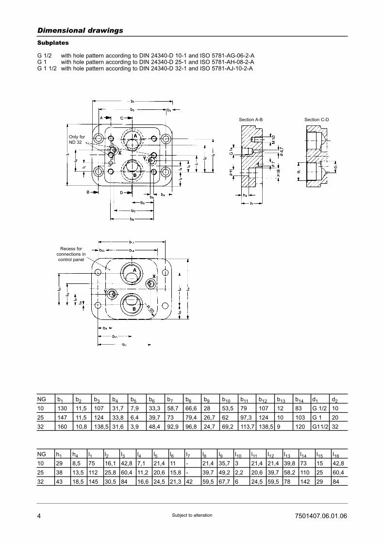
4 7501407.06.01.06Subject to alteration
Dimensional drawings
Subplates
G 1/2 with hole pattern according to DIN 24340-D 10-1 and ISO 5781-AG-06-2-AG 1 with hole pattern according to DIN 24340-D 25-1 and ISO 5781-AH-08-2-AG 1 1/2 with hole pattern according to DIN 24340-D 32-1 and ISO 5781-AJ-10-2-A
NG
10
25
32
b1
130
147
160
b2
11,5
11,5
10,8
b3
107
124
138,5
b4
31,7
33,8
31,6
b5
7,9
6,4
3,9
b6
33,3
39,7
48,4
b7
58,7
73
92,9
b8
66,6
79,4
96,8
b9
28
26,7
24,7
b10
53,5
62
69,2
b11
79
97,3
113,7
b12
107
124
138,5
b13
12
10
9
b14
83
103
120
d1
G 1/2
G 1
G11/2
d2
10
20
32
NG
10
25
32
h1
29
38
43
h4
8,5
13,5
18,5
l1
75
112
145
l2
16,1
25,8
30,5
l3
42,8
60,4
84
l4
7,1
11,2
16,6
l5
21,4
20,6
24,5
l6
11
15,8
21,3
l7
-
-
42
l8
21,4
39,7
59,5
l9
35,7
49,2
67,7
l10
3
2,2
6
l11
21,4
20,6
24,5
l12
21,4
39,7
59,5
l13
39,8
58,2
78
l14
73
110
142
l15
15
25
29
l16
42,8
60,4
84
Only for
ND 32
Recess for
connections in
control panel
Section A-B Section C-D

Designation
Spring
Pressure stage 70
Pressure stage 90:
Spring
Spring
Spring
Nozzle (ø 1,2 mm)
Nozzle (ø 1,1 mm)
Nozzle (ø 0,8 mm)
Valve seat
Cone
O-ring (17,1 x 2,6)
O-ring (28,2 x 2,6)
O-ring (37,7 x 3,5)
O-ring (20,4 x 1,8)
O-ring (28,2 x 3,5)
O-ring (36,1 x 3,5)
Part
1
2
2
2
3
4
5
6
7
8
8
8
9
9
9
57501407.06.01.06 Subject to alteration
Spare parts (Numer of pieces)
NG 10
1
1
1
-
-
2
1
1
1
1
2
-
-
1
-
-
NG 25
1
1
-
1
-
2
1
1
1
1
-
2
-
-
2
-
NG 32
1
1
-
-
1
2
1
1
1
1
-
-
2
-
-
2
Cat. No.
07018100701853
07223180722319072232005676760568648049841607261790499833070129007012970701350070125907013440701349
Designation
O-ring (77,7 x 1,8)
O-ring (20,4 x 1,8)
O-ring (9,2 x 1,8)
Lock cylinder
with key
Key
Part
10
11
12
13
14
NG 10
2
1
3
1
1
NG 25
2
1
3
1
1
NG 32
2
1
3
1
1
Cat. No.
0701621070125907012520568519
0660051
Spare parts
Spare parts
Spare parts
8...12
8...12
8...12
1
-
-
-
1
-
-
-
1
072655007266990726645
Spare parts drawings
D M K..H... D M K..HV...
D M K..HK...
Spare parts kits
Cylinder bolt
(M10 x 90
DIN 912-10.9)
Cylinder bolt
(M10 x 100
DIN 912-10.9)
-
-
4
-
4
-
-
6
0700462
0700465
Mounting bolts

6 7501407.06.01.06Subject to alteration
Notes:

2-way pressure reducing valveNG 10, 25 and 32
indirectly-controlledInterface to DIN 24 340 and ISO
PN [pmax.] = 315 bar 7501407.06.01.06
DesignThe pressure reducing valves of Type D M K areindirectly-controlled spool-type valves.
ActuationThe pressure is set manually by means of a rotaryknob. The setting can, if desired, be safeguarded bymeans of locking (E 10-closure) or by means of a leadseal.
MountingThe units are bolted on subplates and sealed byO-rings.
Line connectionSubplate, interface toDIN 24 340 and ISO.
• High flow rating• Sensitive adjustment• Stable control characteristics
Description (standard units)
Features
Type codePressure reducing valveD M K ... ... G ... 001 ... O ...
1 2 3 4 5
SubplateP DM ... G ... 001 ... O O
1 2 3
1 Nominal size NG:102532
2 Actuation: H – Manual setting
HV – Manual setting (lockable)
HK – Set-screw with cover(can be lead sealed)
3 Pressure- 70 – Up to 100 barsetting range: 90 – Up to 315 bar
4 Engineering 2version:
5 Sealing O – Perbunanmaterial: V – Viton
1 Nomin: 102532
2 Line connection: 4 – G 1/2 (Internal- NG 106 – G 1 thread NG 258 – G 1 1/2 to NG 32
DIN ISO228/1)
3 Engineering version: 1
HERION Systemtechnik GmbHUntere Talstraße 65
D-71263 Weil der Stadt-Merklingen
Tel.: +49 (0) 70 33/30 18-0
Fax: +49 (0) 70 33/30 18-10
www.herion-systemtechnik.de
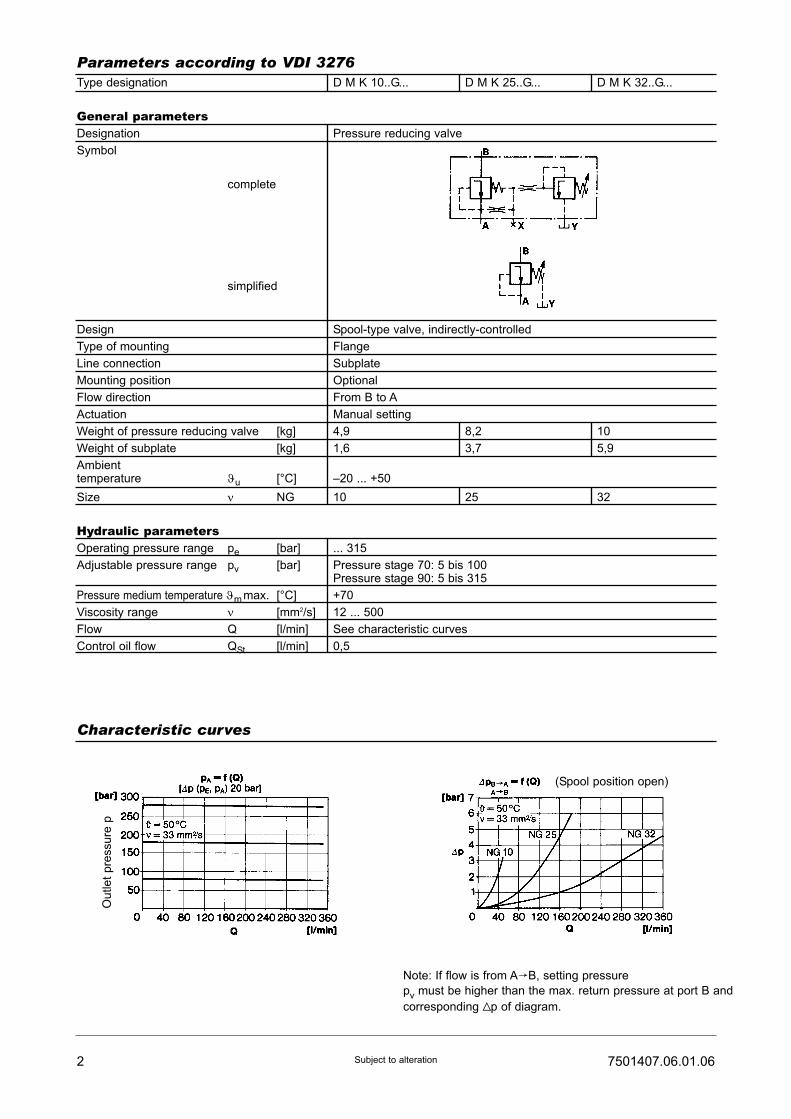
2 7501407.06.01.06Subject to alteration
Type designation D M K 10..G... D M K 25..G... D M K 32..G...
General parametersDesignation Pressure reducing valve
Symbol
complete
simplified
Design Spool-type valve, indirectly-controlled
Type of mounting Flange
Line connection Subplate
Mounting position Optional
Flow direction From B to A
Actuation Manual setting
Weight of pressure reducing valve [kg] 4,9 8,2 10
Weight of subplate [kg] 1,6 3,7 5,9
Ambienttemperature ϑu [°C] –20 ... +50
Size ν NG 10 25 32
Hydraulic parametersOperating pressure range pe [bar] ... 315
Adjustable pressure range pv [bar] Pressure stage 70: 5 bis 100Pressure stage 90: 5 bis 315
Pressure medium temperature ϑm max. [°C] +70
Viscosity range ν [mm2/s] 12 ... 500
Flow Q [l/min] See characteristic curves
Control oil flow QSt [l/min] 0,5
Parameters according to VDI 3276
Characteristic curves
Note: If flow is from AfB, setting pressure
pv must be higher than the max. return pressure at port B and
corresponding Vp of diagram.
Outlet
pre
ssure
p
(Spool position open)

37501407.06.01.06 Subject to alteration
The units are designated by their type number. Thecomposition of this number can be drawn from the typecode. The standard versions are listed in the typesurvey. When ordering any of the standard versions,please state type number as well as catalog number topreclude possible misinterpretations. When inquiringabout or ordering units not listed in our type survey ofthis publication, the type number made up by you bymeans of the type code, however, will do. Thecorresponding catalog number will then be stated in ourconfirmation of order. Units with flanged connection aredelivered complete with fixing bolts and O-rings. Thesubplate must be ordered separately.
Wanted: Pressure reducing valve NG 10 for flangedmounting with manual setting. Setting pressure max.315 bar, with mating subplate.
Pressure reducing valve:Type-No.: D M K 10 H G 90 001 2 O OCat. No.: 6058600
Subplate:Type-No.: P DM 10 G 4 001 1 O OCat. No.: 2840002
Ordering
Type survey (standard versions)
Example of how to order
NG
10
25
32
Q[l/min]
140
150
350
pv max.[bar]
100315
100315
100315
Actuation
Manual setting
Line connection
Subplate G 1/2P DM 10 G 4 001 1 O O2840002Subplate G 1P DM 25 G 6 001 1 O O2840003Subplate G 1 1/2P DM 32 G 8 001 1 O O2840004
Typ
D M K 10 H G 70 001 2 OOD M K 10 H G 90 001 2 OO
D M K 25 H G 70 001 2 OOD M K 25 H G 90 001 2 OO
D M K 32 H G 70 001 2 OOD M K 32 H G 90 001 2 OO
Cat. No.
60584006058600
60588006059000
60592006059400
Dimensional drawings
Pressure reducing valves D M K..H... D M K..HV...
NG
10
25
32
b1
188,5
103,5
119
b2
11
12
11
h1
86
86
98
h2
168
168
182
h3
183
183
197
h4
163
163
177
l1
135
176
178
l2
31
51
37
D M K..HK...
max. tightening torgue
MA = 62 Nm
Check nut
SW 17
Check nut
SW 17

4 7501407.06.01.06Subject to alteration
Dimensional drawings
Subplates
G 1/2 with hole pattern according to DIN 24340-D 10-1 and ISO 5781-AG-06-2-AG 1 with hole pattern according to DIN 24340-D 25-1 and ISO 5781-AH-08-2-AG 1 1/2 with hole pattern according to DIN 24340-D 32-1 and ISO 5781-AJ-10-2-A
NG
10
25
32
b1
130
147
160
b2
11,5
11,5
10,8
b3
107
124
138,5
b4
31,7
33,8
31,6
b5
7,9
6,4
3,9
b6
33,3
39,7
48,4
b7
58,7
73
92,9
b8
66,6
79,4
96,8
b9
28
26,7
24,7
b10
53,5
62
69,2
b11
79
97,3
113,7
b12
107
124
138,5
b13
12
10
9
b14
83
103
120
d1
G 1/2
G 1
G11/2
d2
10
20
32
NG
10
25
32
h1
29
38
43
h4
8,5
13,5
18,5
l1
75
112
145
l2
16,1
25,8
30,5
l3
42,8
60,4
84
l4
7,1
11,2
16,6
l5
21,4
20,6
24,5
l6
11
15,8
21,3
l7
-
-
42
l8
21,4
39,7
59,5
l9
35,7
49,2
67,7
l10
3
2,2
6
l11
21,4
20,6
24,5
l12
21,4
39,7
59,5
l13
39,8
58,2
78
l14
73
110
142
l15
15
25
29
l16
42,8
60,4
84
Only for
ND 32
Recess for
connections in
control panel
Section A-B Section C-D
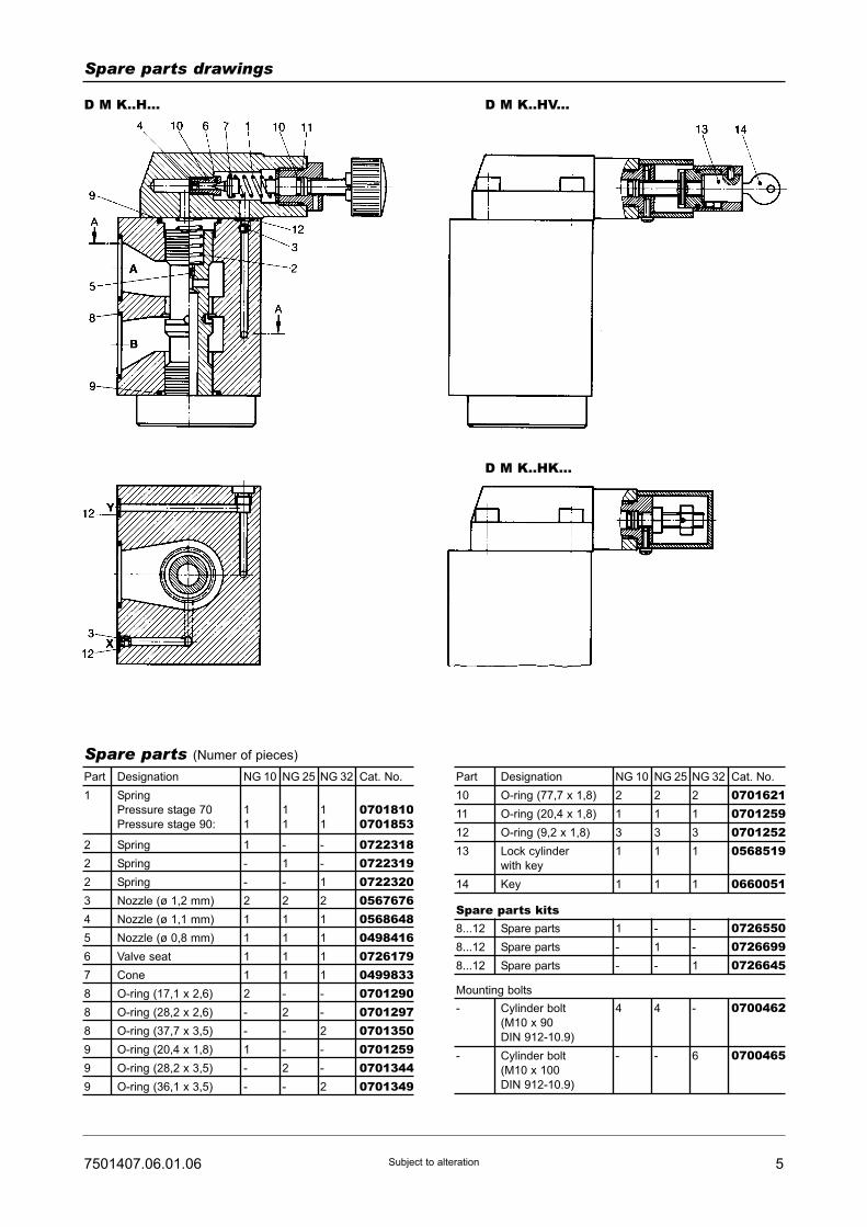
Designation
Spring
Pressure stage 70
Pressure stage 90:
Spring
Spring
Spring
Nozzle (ø 1,2 mm)
Nozzle (ø 1,1 mm)
Nozzle (ø 0,8 mm)
Valve seat
Cone
O-ring (17,1 x 2,6)
O-ring (28,2 x 2,6)
O-ring (37,7 x 3,5)
O-ring (20,4 x 1,8)
O-ring (28,2 x 3,5)
O-ring (36,1 x 3,5)
Part
1
2
2
2
3
4
5
6
7
8
8
8
9
9
9
57501407.06.01.06 Subject to alteration
Spare parts (Numer of pieces)
NG 10
1
1
1
-
-
2
1
1
1
1
2
-
-
1
-
-
NG 25
1
1
-
1
-
2
1
1
1
1
-
2
-
-
2
-
NG 32
1
1
-
-
1
2
1
1
1
1
-
-
2
-
-
2
Cat. No.
07018100701853
07223180722319072232005676760568648049841607261790499833070129007012970701350070125907013440701349
Designation
O-ring (77,7 x 1,8)
O-ring (20,4 x 1,8)
O-ring (9,2 x 1,8)
Lock cylinder
with key
Key
Part
10
11
12
13
14
NG 10
2
1
3
1
1
NG 25
2
1
3
1
1
NG 32
2
1
3
1
1
Cat. No.
0701621070125907012520568519
0660051
Spare parts
Spare parts
Spare parts
8...12
8...12
8...12
1
-
-
-
1
-
-
-
1
072655007266990726645
Spare parts drawings
D M K..H... D M K..HV...
D M K..HK...
Spare parts kits
Cylinder bolt
(M10 x 90
DIN 912-10.9)
Cylinder bolt
(M10 x 100
DIN 912-10.9)
-
-
4
-
4
-
-
6
0700462
0700465
Mounting bolts

6 7501407.06.01.06Subject to alteration
Notes:
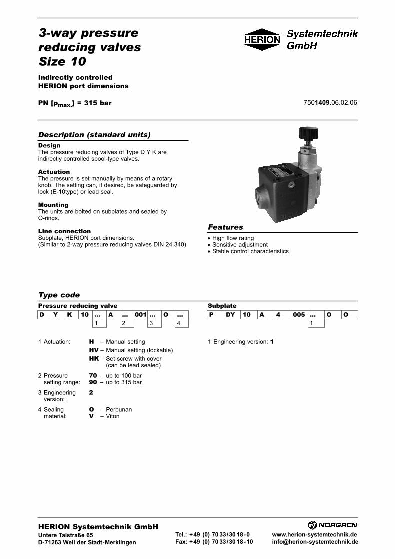
3-way pressurereducing valvesSize 10Indirectly controlledHERION port dimensions
PN [pmax.] = 315 bar 7501409.06.02.06
DesignThe pressure reducing valves of Type D Y K areindirectly controlled spool-type valves.
ActuationThe pressure is set manually by means of a rotaryknob. The setting can, if desired, be safeguarded bylock (E-10type) or lead seal.
MountingThe units are bolted on subplates and sealed byO-rings.
Line connectionSubplate, HERION port dimensions.(Similar to 2-way pressure reducing valves DIN 24 340)
• High flow rating• Sensitive adjustment• Stable control characteristics
Description (standard units)
Features
Type codePressure reducing valveD Y K 10 ... A ... 001 ... O ...
1 2 3 4
SubplateP DY 10 A 4 005 ... O O
1
1 Actuation: H – Manual setting
HV – Manual setting (lockable)
HK – Set-screw with cover(can be lead sealed)
2 Pressure 70 – up to 100 barsetting range: 90 – up to 315 bar
3 Engineering 2version:
4 Sealing O – Perbunanmaterial: V – Viton
1 Engineering version: 1
HERION Systemtechnik GmbHUntere Talstraße 65
D-71263 Weil der Stadt-Merklingen
Tel.: +49 (0) 70 33/30 18-0
Fax: +49 (0) 70 33/30 18-10
www.herion-systemtechnik.de
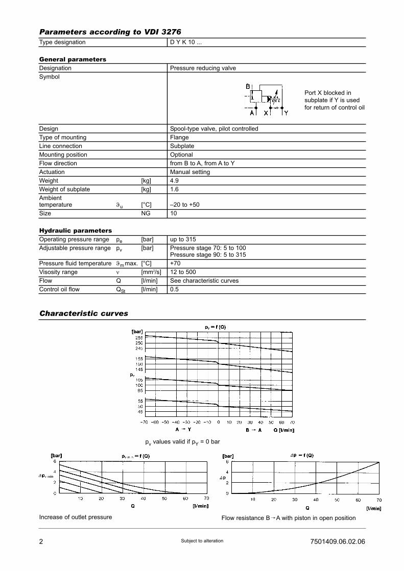
2 7501409.06.02.06Subject to alteration
Type designation D Y K 10 ...
General parametersDesignation Pressure reducing valve
Symbol
Design Spool-type valve, pilot controlled
Type of mounting Flange
Line connection Subplate
Mounting position Optional
Flow direction from B to A, from A to Y
Actuation Manual setting
Weight [kg] 4.9
Weight of subplate [kg] 1.6
Ambienttemperature ϑu [°C] –20 to +50
Size ν NG 10
Hydraulic parametersOperating pressure range pe [bar] up to 315
Adjustable pressure range pv [bar] Pressure stage 70: 5 to 100Pressure stage 90: 5 to 315
Pressure fluid temperature ϑm max. [°C] +70
Visosity range ν [mm2/s] 12 to 500
Flow Q [l/min] See characteristic curves
Control oil flow QSt [l/min] 0.5
Parameters according to VDI 3276
Characteristic curves
Flow resistance BfA with piston in open position
Port X blocked in
subplate if Y is used
for return of control oil
pv values valid if pY = 0 bar
Increase of outlet pressure

37501409.06.02.06 Subject to alteration
The units are designated by their type number. Thecomposition of this number can be drawn from the typecode. The standard versions are listed in the typesurvey. When ordering any of the standard versions,please state type number as well as catalog number topreclude possible misinterpretations.When inquiring about or ordering units not listed in ourtype survey of this publication, the type number madeup by you by means of the type code, however, will do.The corresponding catalog number will then be statedin our confirmation of order. Units with flanged connec-tion are delivered complete with mounting bolts andO-rings. The subplate must be ordered separately.
2-way pressure reducing valve size 10 for flangedmounting with manual setting. Setting pressure max.315 bar, with mating subplate.
3-way pressure reducing valve:Type No.: D Y K 10 H A 90 001 2 O OCat. No.: 6014254
Subplate:Type No.: P DY 10 A 4 005 1 O OCat. No.: 2840085
Ordering
Type survey (standard versions)
Example of order
Size
10
Q[l/min]
70
pv max.[bar]
100315
Actuation
Manual
Line connection
Subplate G 1/2P DY 10 A 4 005 1 O O(Port X closed)2840085
Type
1) D Y K 10 H A 70 001 2 OO1) D Y K 10 H A 90 001 2 OO
Cat No.
60142536014254
Dimensional drawings (in mm)
Pressure reducing valves
D Y K..H... D Y K..HK...
D Y K..HV...
1) Note: Unit is furnished with internal control oil return via port Y (standard version).For units with external control oil return via port X, not instructions on spare parts drawings.

Designation
Spring pressure stage 70
pressure stage 90
O-ring (17.1 x 2.6)
O-ring (7.7 x 1.8)
O-ring (20.3 x 1.8)
O-ring (9.2 x 1.8)
Lock cylinder with key
Key
Part
1
2
3
5
6
7
8
Qty.
1
5
2
1
2
1
1
4 7501409.06.02.06Subject to alteration
Spare parts Spar parts kits
Dimensional drawings (in mm)
SubplateP DY 10 A 4 005 1 O O
Cat. No.
07018100701853070129007016210701259070125205685190660051
Cat. No. 07273121 Set of spare parts consists of parts 2 to 6.
Cylinder bolt
(M10 x 90 DIN 912-10.9)
- 4 0700462Mounting bolts, tightening torque = 69 Nm
Spare parts drawings
D Y K..H... D Y K..HV...
Closed by means of screw 0700514
if control oil is returned externally via X.
Section A - B

Line connection: Mounting:
Subplate On subplate be means of boltsSealing by means of O-rings
Threaded port On equipment rack, etc. by means of bolts
Plug-in design Complete unit is screwed intothreaded bore
Pressure relief valvesSize 10
direct operatedinterface to DIN 24 340 and ISO 6264
PN [pmax.] = 315 bar 7501410.06.02.06
DesignThe pressure relief valves of type D B C 10 are direct-operated seat valves.
ActuationThe pressure is set manually by means of a rotaryknob. The setting can, if desired, be locked (E10-closure) or lead sealed.
Line connection and mountingThe mounting of the units depends on the line connec-tion and type:
• High flow rating• Insensitive to vibration
Description (standard units)
Features
Type key
D B C 10 ... ... ... ... 001 ... O ...1 2 3 4 5 6
SubplateP DB 10 G ... 001 ... O O
1 2
1 Actuation: H – Manual setting
HV – Manual setting(lockable)
HK – Set-screw with cover(can be lead sealed)
2 Line connection: S5 – Threaded port -flange mounting
E – Plug-in design
G – Subplate, interfaceto DIN 24 340-E10 andISO 6264-AR-06-2-A
3 Port size: 5 – G 3/4(except plug-in- (Internal thread todesign and subplate DIN ISO 228/1)
4 Pressure 50 – up to 150 barsetting range: 70 – up to 100 bar
80 – up to 210 bar90 – up to 315 bar
5 Engineeringversion: 1
2 – (with subplate)
6 Sealing material: O – PerbunanV – Viton
1 Line connection: 4 – G 1/2 (Internal thread1) 5 – G 3/4 to DIN ISO
228/1)
2 Engineering version: 1
HERION Systemtechnik GmbHUntere Talstraße 65
D-71263 Weil der Stadt-Merklingen
Tel.: +49 (0) 70 33/30 18-0
Fax: +49 (0) 70 33/30 18-10
www.herion-systemtechnik.de
1) Upon request
Pressure relief valve

Type designation D B C 10...S5.. D B C 10...G.. D B C 10...E..
General parametersDesignation Pressure relief valve
Symbol
Design Seat valve, directoperated
Type mounting FlangePlug-in design
Line connection Thread Subplate
Mounting position Optional
Flow direction From P to T
Actuation By hand
Weight [kg] 2.6 2.6 0.7
Weight of subplate [kg] - 2 -
Ambient temperaturerange ϑu [°C] –20 to +50
Size NG 10
Hydraulic parametersOperating pressure range pe max. [bar] Up to 315
Adjustable pressure range pv [bar] pv min.: see characteristic curvepv max.:Pressure stage: 50: 150Pressure stage: 70: 100Pressure stage: 80: 210Pressure stage: 90: 315
Pressure fluid temperature ϑm max. [°C] +70
Viscosity range ν [mm2/s] 12 bis 500
Flow Q [l/min] See characteristic curve
2 7501410.06.02.06Subject to alteration
Parameters according to VDI 3276
Characteristic curve
pv min. = smallest adjustable pressure under which valve remains closedby pressure spring Q = 0 (l/min).
Pre
ssure
sta
ge
Pre
ssure
sta
ge
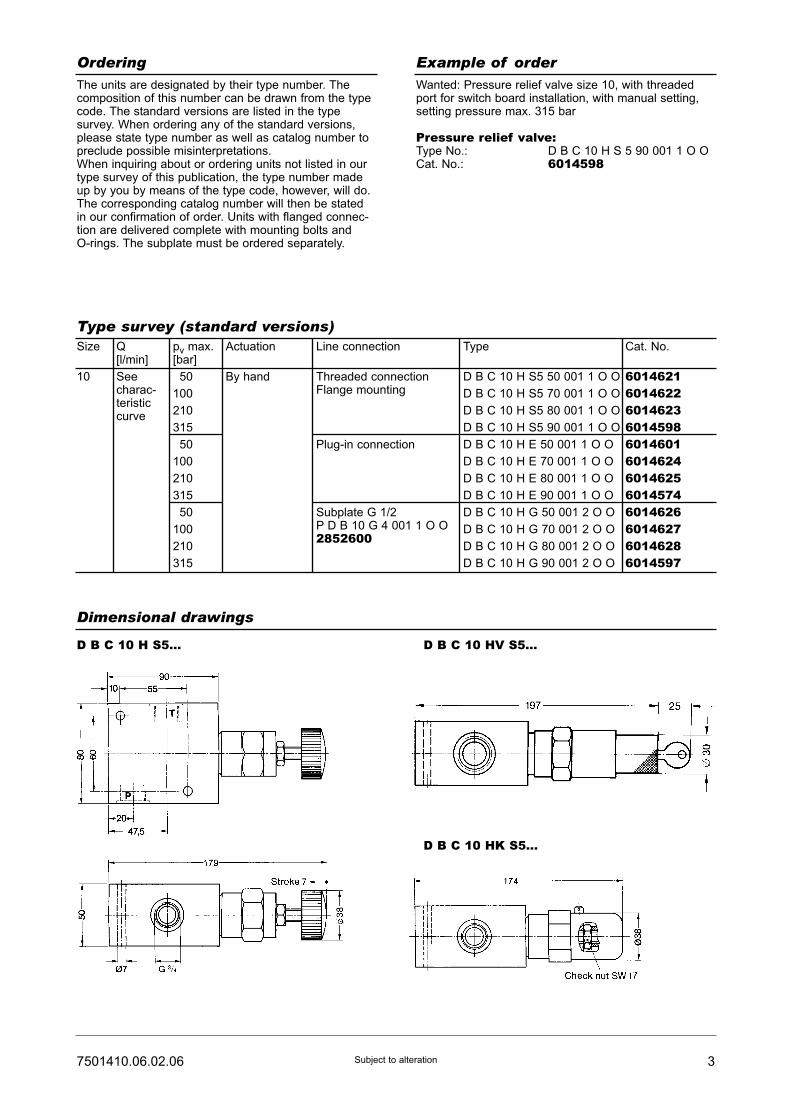
37501410.06.02.06 Subject to alteration
The units are designated by their type number. Thecomposition of this number can be drawn from the typecode. The standard versions are listed in the typesurvey. When ordering any of the standard versions,please state type number as well as catalog number topreclude possible misinterpretations.When inquiring about or ordering units not listed in ourtype survey of this publication, the type number madeup by you by means of the type code, however, will do.The corresponding catalog number will then be statedin our confirmation of order. Units with flanged connec-tion are delivered complete with mounting bolts andO-rings. The subplate must be ordered separately.
Wanted: Pressure relief valve size 10, with threadedport for switch board installation, with manual setting,setting pressure max. 315 bar
Pressure relief valve:Type No.: D B C 10 H S 5 90 001 1 O OCat. No.: 6014598
Ordering
Type survey (standard versions)
Example of order
Dimensional drawings
Size
10
Q[l/min]
Seecharac-teristiccurve
pv max.[bar]
150
100
210
315
150
100
210
315
150
100
210
315
Actuation
By hand
Type
D B C 10 H S5 50 001 1 O O
D B C 10 H S5 70 001 1 O O
D B C 10 H S5 80 001 1 O O
D B C 10 H S5 90 001 1 O O
D B C 10 H E 50 001 1 O O
D B C 10 H E 70 001 1 O O
D B C 10 H E 80 001 1 O O
D B C 10 H E 90 001 1 O O
D B C 10 H G 50 001 2 O O
D B C 10 H G 70 001 2 O O
D B C 10 H G 80 001 2 O O
D B C 10 H G 90 001 2 O O
Cat. No.
601462160146226014623601459860146016014624601462560145746014626601462760146286014597
Line connection
Threaded connectionFlange mounting
Plug-in connection
Subplate G 1/2P D B 10 G 4 001 1 O O 2852600
D B C 10 H S5... D B C 10 HV S5...
D B C 10 HK S5...

4 7501410.06.02.06Subject to alteration
Dimensional drawings
Pressure relief valveD B C 10 H E...Tightening torque approx. 140 Nm
Subplate with hole pattern to DIN 24 340-E10 and ISO 6264-AR-06-2-AG 1/2
Mounting boreto D B C 10..E...
D B C 10 HV E... D B C 10 HK E...
D B C 10 H G... D B C 10 HV G...
D B C 10 HK G...
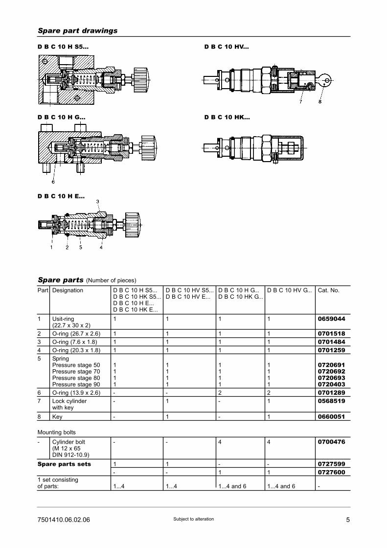
57501410.06.02.06 Subject to alteration
Spare part drawings
D B C 10 H S5... D B C 10 HV...
D B C 10 H G...
D B C 10 H E...
D B C 10 HK...
Designation
Usit-ring(22.7 x 30 x 2)
O-ring (26.7 x 2.6)
O-ring (7.6 x 1.8)
O-ring (20.3 x 1.8)
SpringPressure stage 50Pressure stage 70Pressure stage 80Pressure stage 90
O-ring (13.9 x 2.6)
Lock cylinderwith key
Key
Part
1
2
3
4
5
6
7
8
Cylinder bolt(M 12 x 65DIN 912-10.9)
-
Spare parts (Number of pieces)
D B C 10 H S5...D B C 10 HK S5...D B C 10 H E...D B C 10 HK E...
1
1
1
1
1111
-
-
-
-
1
-
1...4
D B C 10 HV S5...D B C 10 HV E...
1
1
1
1
1111
-
1
1
-
1
-
1...4
D B C 10 H G...D B C 10 HK G...
1
1
1
1
1111
2
-
-
4
-
1
1...4 and 6
D B C 10 HV G...
1
1
1
1
1111
2
1
1
4
-
1
1...4 and 6
Cat. No.
0659044
070151807014840701259
072069107206920720693072040307012890568519
0660051
0700476
07275990727600
-
Mounting bolts
Spare parts sets
1 set consistingof parts:
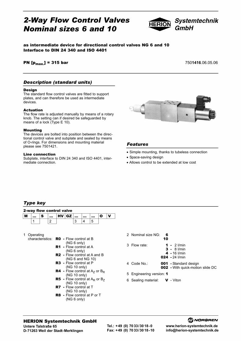
2-Way Flow Control ValvesNominal sizes 6 and 10
as intermediate device for directional control valves NG 6 and 10Interface to DIN 24 340 and ISO 4401
PN [pmax.] = 315 bar 7501416.06.05.06
DesignThe standard flow control valves are fitted to supportplates, and can therefore be used as intermediatedevices.
ActuationThe flow rate is adjusted manually by means of a rotaryknob. The setting can if desired be safeguarded bymeans of a lock (Type E 10).
MountingThe devices are bolted into position between the direc-tional control valve and subplate and sealed by meansof O-rings. For dimensions and mounting materialplease see 7501421.
Line connectionSubplate, interface to DIN 24 340 and ISO 4401, inter-mediate connection.
• Simple mounting, thanks to tubeless connection
• Space-saving design
• Allows control to be extended at low cost
Description (standard units)
Features
Type key
1 Operatingcharacteristics: R0 - Flow control at B
(NG 6 only)R1 - Flow control at A
(NG 6 only)R2 - Flow control at A and B
(NG 6 and NG 10)R3 - Flow control at P
(NG 10 only)R4 - Flow control at AZ or BR
(NG 10 only)R5 - Flow control at AR or BZ
(NG 10 only)R7 - Flow control at T
(NG 10 only)R8 - Flow control at P or T
(NG 6 only)
HERION Systemtechnik GmbHUntere Talstraße 65
D-71263 Weil der Stadt-Merklingen
Tel.: +49 (0) 70 33/30 18-0
Fax: +49 (0) 70 33/30 18-10
www.herion-systemtechnik.de
2 Nominal size NG: 610
3 Flow rate: 1 - 12 l/min3 - 18 l/min4 - 16 l/min
024 - 24 l/min
4 Code No.: 001 - Standard design002 - With quick-motion slide DC
5 Engineering version: 16 Sealing material: V - Viton
M ... S ... HV GZ ... ... ... O V1 2 3 4 5
2-way flow control valve

General parametersDesignation 2-way flow control valve
Symbol See type survey
Design Orifice-type restrictor with upstream differential-pressure piston
Type of mounting Intermediate mounting
Line connection Intermediate connection
Mounting position Any
Flow direction See symbol in type survey
Actuation Manual adjustment
Ambient temperature range ϑu [°C] –20 ... +50
Nominal size NG 6 10
Hydraulic parameters for flow control valvesOperating pressure range pe max. [bar] ... 315
Operating pressure gradient Q [l/min] 2 8 16 24
with VpA-B min/max [bar] 4/100 12.5/300 20/300
Pressure fluid temperature ϑm max. [°C] +70
Viscosity range ν [mm2/s] 12 ... 500
Flow Qmax [l/min] 0.02 ... 16
Actuating moment Mb [Ncm] 10
Angle of rotation α [o] Approx. 345
Grade of filtration upstream
of flow control valve s [mm] 0.01 ... Q = 500 cm3/min
0.05 from Q > 500 cm3/min onwards
Electrical parameters for the directional control valveDC
Switching time t approx. ton [ms] 50
toff [ms] 30
Number of switchings/h approx. 15000
Rated voltage UN [V] Standard voltages
(other voltages available on request) 24
Power consumption P20 [W] DC 32
P20 [VA] AC -
Duty cycle EDrel [%] 100
Degree of protection for solenoid
an electrical connection to DIN 40050 IP 54
Electrical connection Plug socket to DIN 43 650
For other parameters, see 7500990 for the flow control valve and 7501295 for the directional control valve.
2 7501416.06.05.06Subject to alteration
Parameters according to VDI 3268
Characteristic curvesNG 6 NG 10

37501416.06.05.06 Subject to alteration
Type survey (standard design)NG Q
[l/min]VpA-B[bar]
Symbol 1) Type Cat. No.
6 0,02 ... 120,03 ... 180,03 ... 160,03 ... 24
13,5 ... 10010 ... 30510 ... 30515 ... 300
M R0 S 16 HV GZ 1 001 1 O VM R0 S 16 HV GZ 3 001 1 O VM R0 S 16 HV GZ 4 001 1 O VM R0 S 16 HV GZ 024 001 1 O V
5100037510007151000955100195
10 0,02 ... 120,03 ... 180,03 ... 16
13,5 ... 10010 ... 30510 ... 305
M R4 S 10 HV GZ 1 001 1 O VM R4 S 10 HV GZ 3 001 1 O VM R4 S 10 HV GZ 4 001 1 O V
510009351000415100166
6 0,02 ... 120,03 ... 180,03 ... 16
13,5 ... 10010 ... 30510 ... 305
M R1 S 16 HV GZ 1 001 1 O VM R1 S 16 HV GZ 3 001 1 O VM R1 S 16 HV GZ 4 001 1 O V
510003651000635100067
10 0,03 ... 180,03 ... 16
10 ... 30510 ... 305
M R5 S 10 HV GZ 3 001 1 O VM R5 S 10 HV GZ 4 001 1 O V
51000405100085
6 0,02 ... 120,03 ... 180,03 ... 16
13,5 ... 10010 ... 30510 ... 305
M R2 S 16 HV GZ 1 001 1 O VM R2 S 16 HV GZ 3 001 1 O VM R2 S 16 HV GZ 4 001 1 O V
510003851000655100106
10 0,03 ... 180,03 ... 16
10 ... 30510 ... 305
M R2 S 10 HV GZ 3 001 1 O VM R2 S 10 HV GZ 4 001 1 O V
51000425100112
6 0,02 ... 120,03 ... 180,03 ... 16
13,5 ... 10010 ... 30510 ... 305
M R1 S 16 HV GZ 1 001 1 O VM R1 S 16 HV GZ 3 001 1 O VM R1 S 16 HV GZ 4 001 1 O V
510003651000635100067
6 0,02 ... 120,03 ... 180,03 ... 160,03 ... 24
13,5 ... 10010 ... 30510 ... 30515 ... 300
M R0 S 16 HV GZ 1 001 1 O VM R0 S 16 HV GZ 3 001 1 O VM R0 S 16 HV GZ 4 001 1 O VM R0 S 16 HV GZ 024 001 1 O V
5100037510007151000955100195
10 0,02 ... 120,03 ... 180,03 ... 16
13,5 ... 10010 ... 305
M R4 S 10 HV GZ 1 001 1 O VM R4 S 10 HV GZ 3 001 1 O VM R4 S 10 HV GZ 4 001 1 O V
510009351000415100166
10 0,03 ... 180,03 ... 16
10 ... 30510 ... 305
M R5 S 10 HV GZ 3 001 1 O VM R5 S 10 HV GZ 4 001 1 O V
51000405100085
10 0,03 ... 180,03 ... 16
10 ... 30510 ... 305
M R3 S 10 HV GZ 3 001 1 O VM R3 S 10 HV GZ 4 001 1 O V
51000435100086
6 0,02 ... 120,03 ... 180,03 ... 16
13,5 ... 10010 ... 30510 ... 305
M R8 S 16 HV GZ 1 001 1 O VM R8 S 16 HV GZ 3 001 1 O VM R8 S 16 HV GZ 4 001 1 O V
510003951000735100084
6 0,02 ... 120,03 ... 180,03 ... 16
13,5 ... 10010 ... 30510 ... 305
M R8 S 16 HV GZ 1 001 1 O VM R8 S 16 HV GZ 3 001 1 O VM R8 S 16 HV GZ 4 001 1 O V
510003951000735100084
10 0,03 ... 18 10 ... 305 M R7 S 10 HV GZ 3 001 1 O V 5100044
Note: Index letters as follows; R = Return flow control, Z = Feed flow control, G = Equipment side, P = Subplate side.
Other combinations on request.1) Connection R = NG 10 only

4 7501416.06.05.06Subject to alteration
Ordering Example of order
The units are designated by their type number. Thecomposition of this number can be drawn from the typecode. The standard versions are listed in the typesurvey. When ordering any of the standard versions,please state type number as well as catalog number topreclude possible misinterpretations.When inquiring about or ordering units not listed in ourtype survey of this publication, the type number madeup by you by means of the type code, however, will do.The corresponding catalog number will then be statedin our confirmation of order.The subplate and, if necessary, mounting material forvalve combinations must be ordered separately. OnlyO-rings are included in the delivery.
2-way flow control valve as intermediate device nominalsize 6 for flow rates from 0.02 to 2 l/min, return flowcontrol at B.
2-way flow control valve:Type No.: M R0 S 6 HV GZ 1 001 1 O VCat. No.: 5100037
Type survey (standard design)NG Q
[l/min]VpA-B[bar]
Symbol 1) Type Cat. No.
6 0,02 ... 120,03 ... 180,03 ... 16
13,5 ... 10010 ... 30510 ... 305
M R1 S 16 HV GZ 1 002 1 O VM R1 S 16 HV GZ 3 002 1 O VM R1 S 16 HV GZ 4 002 1 O V
5100050.72345100074.72345100119.7234
6 0,02 ... 120,03 ... 180,03 ... 16
13,5 ... 10010 ... 30510 ... 305
M R1 S 16 HV GZ 1 002 1 O VM R1 S 16 HV GZ 3 002 1 O VM R1 S 16 HV GZ 4 002 1 O V
5100050.72345100074.72345100119.7234
6 0,02 ... 120,03 ... 180,03 ... 16
13,5 ... 10010 ... 30510 ... 305
M R0 S 16 HV GZ 1 002 1 O VM R0 S 16 HV GZ 3 002 1 O VM R0 S 16 HV GZ 4 002 1 O V
5100051.72345100066.72345100129.7234
6 0,02 ... 120,03 ... 180,03 ... 16
13,5 ... 10010 ... 30510 ... 305
M R0 S 16 HV GZ 1 002 1 O VM R0 S 16 HV GZ 3 002 1 O VM R0 S 16 HV GZ 4 002 1 O V
5100051.72345100066.72345100129.7234
6 0,02 ... 120,03 ... 180,03 ... 16
13,5 ... 10010 ... 30510 ... 305
M R8 S 16 HV GZ 1 002 1 O VM R8 S 16 HV GZ 3 002 1 O VM R8 S 16 HV GZ 4 002 1 O V
5100061.72345100076.72345100091.7234
6 0,02 ... 120,03 ... 180,03 ... 16
13,5 ... 10010 ... 30510 ... 305
M R8 S 16 HV GZ 1 002 1 O VM R8 S 16 HV GZ 3 002 1 O VM R8 S 16 HV GZ 4 002 1 O V
5100061.72345100076.72345100091.7234
10 0,03 ... 180,03 ... 16
10 ... 30510 ... 305
M R5 S 10 HV GZ 3 002 1 O VM R5 S 10 HV GZ 4 002 1 O V
5100052.72345100088.7234
10 0,02 ... 120,03 ... 180,03 ... 16
13,5 ... 10010 ... 30510 ... 305
M R4 S 10 HV GZ 1 002 1 O VM R4 S 10 HV GZ 3 002 1 O VM R4 S 10 HV GZ 4 002 1 O V
5100145.72345100053.72345100087.7234
10 0,02 ... 120,03 ... 180,03 ... 16
13,5 ... 10010 ... 30510 ... 305
M R4 S 10 HV GZ 1 002 1 O VM R4 S 10 HV GZ 3 002 1 O VM R4 S 10 HV GZ 4 002 1 O V
5100145.72345100053.72345100087.7234
10 0,03 ... 180,03 ... 16
10 ... 30510 ... 305
M R5 S 10 HV GZ 3 002 1 O VM R5 S 10 HV GZ 4 002 1 O V
5100052.72345100088.7234
10 0,02 ... 120,03 ... 180,03 ... 16
110 ... 305
M R3 S 10 HV GZ 3 002 1 O VM R3 S 10 HV GZ 4 002 1 O V
5100059.72345100169.7234
10 0,02 ... 120,03 ... 180,03 ... 16
110 ... 30510 ... 305
M R7 S 10 HV GZ 3 002 1 O VM R7 S 10 HV GZ 4 002 1 O V
5100058.72345100183.7234
Note: Index letters as follows; R = Return flow control, Z = Feed flow control, G = Equipment side, P = Subplate side.
Other combinations on request.1) Connection R = NG 10 only
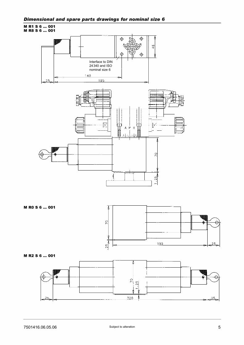
57501416.06.05.06 Subject to alteration
Dimensional and spare parts drawings for nominal size 6
M R1 S 6 ... 001M R8 S 6 ... 001
M R0 S 6 ... 001
M R2 S 6 ... 001
Interface to DIN
24340 and ISO
nominal size 6
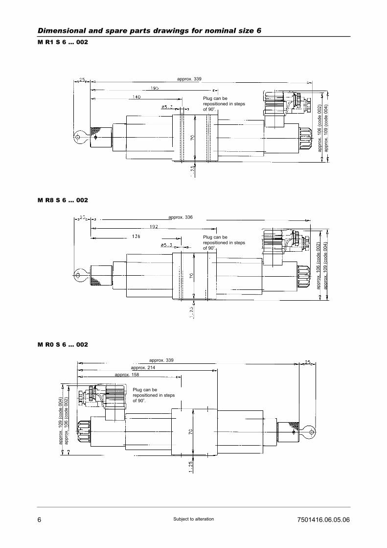
6 7501416.06.05.06Subject to alteration
Dimensional and spare parts drawings for nominal size 6
M R1 S 6 ... 002
M R8 S 6 ... 002
M R0 S 6 ... 002
ap
pro
x.
10
6 (
co
de
00
2)
ap
pro
x.
10
9 (
co
de
00
4)
appro
x.
106 (
code 0
02)
appro
x.
109 (
code 0
04)
approx. 339
approx. 336
Plug can be
repositioned in steps
of 90o.
Plug can be
repositioned in steps
of 90o.
Plug can be
repositioned in steps
of 90o.
approx. 339
approx. 214
approx. 158
appro
x.
109 (
code 0
04)
appro
x.
106 (
code 0
02)

77501416.06.05.06 Subject to alteration
Dimensional and spare parts drawings for nominal size 10
M R3 S 10 ... 001M R7 S 10 ... 001
M R4 S 10 ... 001 (AZ)M R4 S 10 ... 001 (BR)
M R5 S 10 ... 001 (AZ)M R5 S 10 ... 001 (BR)
Interface to DIN 24340 and ISO nominal size 10
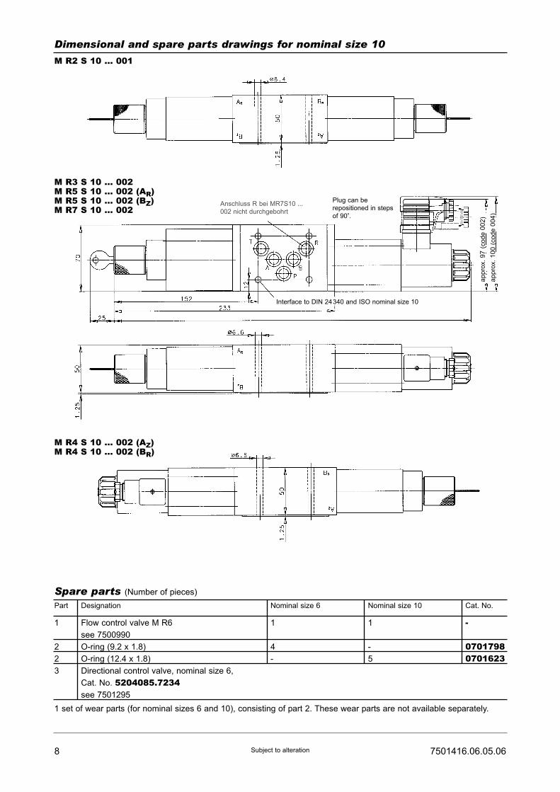
8 7501416.06.05.06Subject to alteration
Spare parts (Number of pieces)
Part
1
2
2
3
Flow control valve M R6
see 7500990
O-ring (9.2 x 1.8)
O-ring (12.4 x 1.8)
Directional control valve, nominal size 6,
Cat. No. 5204085.7234see 7501295
1
4
-
1
-
5
-072655807017980701623ETS0615057
1 set of wear parts (for nominal sizes 6 and 10), consisting of part 2. These wear parts are not available separately.
Designation Nominal size 6 Nominal size 10 Cat. No.
Dimensional and spare parts drawings for nominal size 10
M R2 S 10 ... 001
M R3 S 10 ... 002M R5 S 10 ... 002 (AR)M R5 S 10 ... 002 (BZ)M R7 S 10 ... 002
M R4 S 10 ... 002 (AZ)M R4 S 10 ... 002 (BR)
Plug can be
repositioned in steps
of 90o.
ap
pro
x.
97
(co
de
00
2)
ap
pro
x.
10
0 (
co
de
00
4)
Interface to DIN 24340 and ISO nominal size 10
Anschluss R bei MR7S10 ...
002 nicht durchgebohrt

2-Way Flow Control ValvesNominal sizes 6 and 10
as intermediate device for directional control valves NG 6 and 10Interface to DIN 24 340 and ISO 4401
PN [pmax.] = 315 bar 7501416.06.05.06
DesignThe standard flow control valves are fitted to supportplates, and can therefore be used as intermediatedevices.
ActuationThe flow rate is adjusted manually by means of a rotaryknob. The setting can if desired be safeguarded bymeans of a lock (Type E 10).
MountingThe devices are bolted into position between the direc-tional control valve and subplate and sealed by meansof O-rings. For dimensions and mounting materialplease see 7501421.
Line connectionSubplate, interface to DIN 24 340 and ISO 4401, inter-mediate connection.
• Simple mounting, thanks to tubeless connection
• Space-saving design
• Allows control to be extended at low cost
Description (standard units)
Features
Type key
1 Operatingcharacteristics: R0 - Flow control at B
(NG 6 only)R1 - Flow control at A
(NG 6 only)R2 - Flow control at A and B
(NG 6 and NG 10)R3 - Flow control at P
(NG 10 only)R4 - Flow control at AZ or BR
(NG 10 only)R5 - Flow control at AR or BZ
(NG 10 only)R7 - Flow control at T
(NG 10 only)R8 - Flow control at P or T
(NG 6 only)
HERION Systemtechnik GmbHUntere Talstraße 65
D-71263 Weil der Stadt-Merklingen
Tel.: +49 (0) 70 33/30 18-0
Fax: +49 (0) 70 33/30 18-10
www.herion-systemtechnik.de
2 Nominal size NG: 610
3 Flow rate: 1 - 12 l/min3 - 18 l/min4 - 16 l/min
024 - 24 l/min
4 Code No.: 001 - Standard design002 - With quick-motion slide DC
5 Engineering version: 16 Sealing material: V - Viton
M ... S ... HV GZ ... ... ... O V1 2 3 4 5
2-way flow control valve
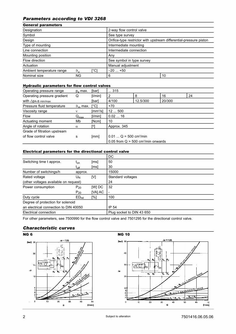
General parametersDesignation 2-way flow control valve
Symbol See type survey
Design Orifice-type restrictor with upstream differential-pressure piston
Type of mounting Intermediate mounting
Line connection Intermediate connection
Mounting position Any
Flow direction See symbol in type survey
Actuation Manual adjustment
Ambient temperature range ϑu [°C] –20 ... +50
Nominal size NG 6 10
Hydraulic parameters for flow control valvesOperating pressure range pe max. [bar] ... 315
Operating pressure gradient Q [l/min] 2 8 16 24
with VpA-B min/max [bar] 4/100 12.5/300 20/300
Pressure fluid temperature ϑm max. [°C] +70
Viscosity range ν [mm2/s] 12 ... 500
Flow Qmax [l/min] 0.02 ... 16
Actuating moment Mb [Ncm] 10
Angle of rotation α [o] Approx. 345
Grade of filtration upstream
of flow control valve s [mm] 0.01 ... Q = 500 cm3/min
0.05 from Q > 500 cm3/min onwards
Electrical parameters for the directional control valveDC
Switching time t approx. ton [ms] 50
toff [ms] 30
Number of switchings/h approx. 15000
Rated voltage UN [V] Standard voltages
(other voltages available on request) 24
Power consumption P20 [W] DC 32
P20 [VA] AC -
Duty cycle EDrel [%] 100
Degree of protection for solenoid
an electrical connection to DIN 40050 IP 54
Electrical connection Plug socket to DIN 43 650
For other parameters, see 7500990 for the flow control valve and 7501295 for the directional control valve.
2 7501416.06.05.06Subject to alteration
Parameters according to VDI 3268
Characteristic curvesNG 6 NG 10
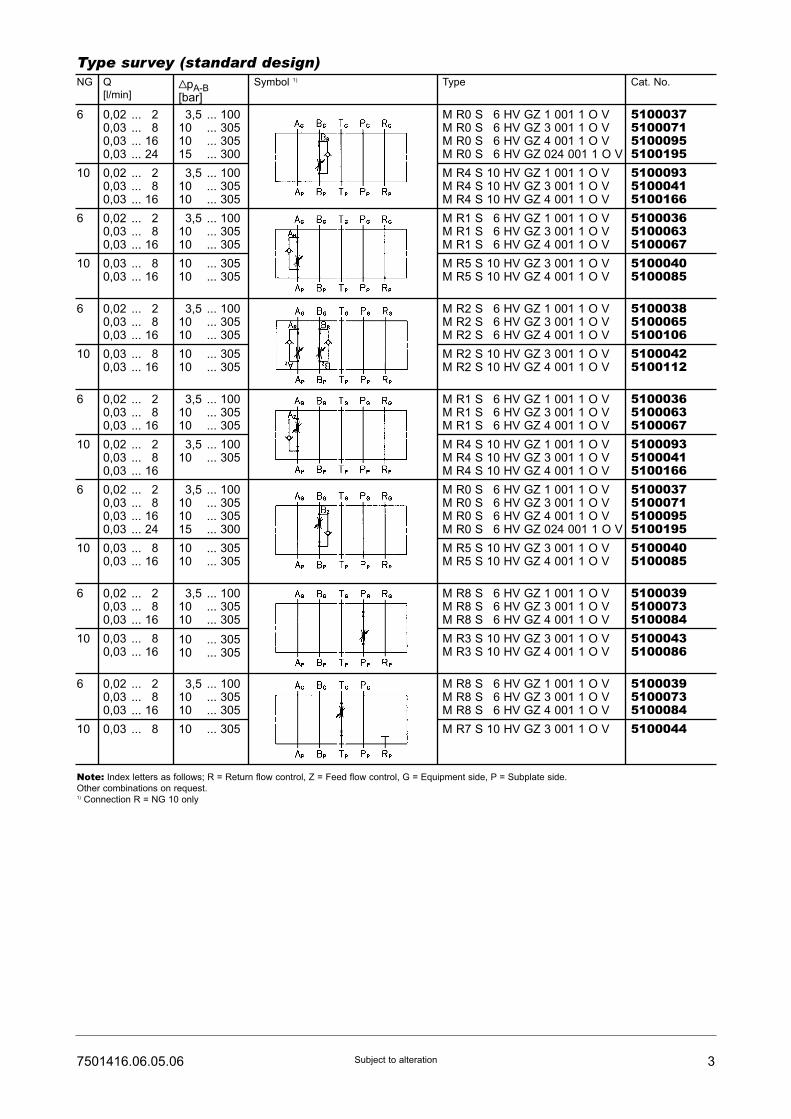
37501416.06.05.06 Subject to alteration
Type survey (standard design)NG Q
[l/min]VpA-B[bar]
Symbol 1) Type Cat. No.
6 0,02 ... 120,03 ... 180,03 ... 160,03 ... 24
13,5 ... 10010 ... 30510 ... 30515 ... 300
M R0 S 16 HV GZ 1 001 1 O VM R0 S 16 HV GZ 3 001 1 O VM R0 S 16 HV GZ 4 001 1 O VM R0 S 16 HV GZ 024 001 1 O V
5100037510007151000955100195
10 0,02 ... 120,03 ... 180,03 ... 16
13,5 ... 10010 ... 30510 ... 305
M R4 S 10 HV GZ 1 001 1 O VM R4 S 10 HV GZ 3 001 1 O VM R4 S 10 HV GZ 4 001 1 O V
510009351000415100166
6 0,02 ... 120,03 ... 180,03 ... 16
13,5 ... 10010 ... 30510 ... 305
M R1 S 16 HV GZ 1 001 1 O VM R1 S 16 HV GZ 3 001 1 O VM R1 S 16 HV GZ 4 001 1 O V
510003651000635100067
10 0,03 ... 180,03 ... 16
10 ... 30510 ... 305
M R5 S 10 HV GZ 3 001 1 O VM R5 S 10 HV GZ 4 001 1 O V
51000405100085
6 0,02 ... 120,03 ... 180,03 ... 16
13,5 ... 10010 ... 30510 ... 305
M R2 S 16 HV GZ 1 001 1 O VM R2 S 16 HV GZ 3 001 1 O VM R2 S 16 HV GZ 4 001 1 O V
510003851000655100106
10 0,03 ... 180,03 ... 16
10 ... 30510 ... 305
M R2 S 10 HV GZ 3 001 1 O VM R2 S 10 HV GZ 4 001 1 O V
51000425100112
6 0,02 ... 120,03 ... 180,03 ... 16
13,5 ... 10010 ... 30510 ... 305
M R1 S 16 HV GZ 1 001 1 O VM R1 S 16 HV GZ 3 001 1 O VM R1 S 16 HV GZ 4 001 1 O V
510003651000635100067
6 0,02 ... 120,03 ... 180,03 ... 160,03 ... 24
13,5 ... 10010 ... 30510 ... 30515 ... 300
M R0 S 16 HV GZ 1 001 1 O VM R0 S 16 HV GZ 3 001 1 O VM R0 S 16 HV GZ 4 001 1 O VM R0 S 16 HV GZ 024 001 1 O V
5100037510007151000955100195
10 0,02 ... 120,03 ... 180,03 ... 16
13,5 ... 10010 ... 305
M R4 S 10 HV GZ 1 001 1 O VM R4 S 10 HV GZ 3 001 1 O VM R4 S 10 HV GZ 4 001 1 O V
510009351000415100166
10 0,03 ... 180,03 ... 16
10 ... 30510 ... 305
M R5 S 10 HV GZ 3 001 1 O VM R5 S 10 HV GZ 4 001 1 O V
51000405100085
10 0,03 ... 180,03 ... 16
10 ... 30510 ... 305
M R3 S 10 HV GZ 3 001 1 O VM R3 S 10 HV GZ 4 001 1 O V
51000435100086
6 0,02 ... 120,03 ... 180,03 ... 16
13,5 ... 10010 ... 30510 ... 305
M R8 S 16 HV GZ 1 001 1 O VM R8 S 16 HV GZ 3 001 1 O VM R8 S 16 HV GZ 4 001 1 O V
510003951000735100084
6 0,02 ... 120,03 ... 180,03 ... 16
13,5 ... 10010 ... 30510 ... 305
M R8 S 16 HV GZ 1 001 1 O VM R8 S 16 HV GZ 3 001 1 O VM R8 S 16 HV GZ 4 001 1 O V
510003951000735100084
10 0,03 ... 18 10 ... 305 M R7 S 10 HV GZ 3 001 1 O V 5100044
Note: Index letters as follows; R = Return flow control, Z = Feed flow control, G = Equipment side, P = Subplate side.
Other combinations on request.1) Connection R = NG 10 only
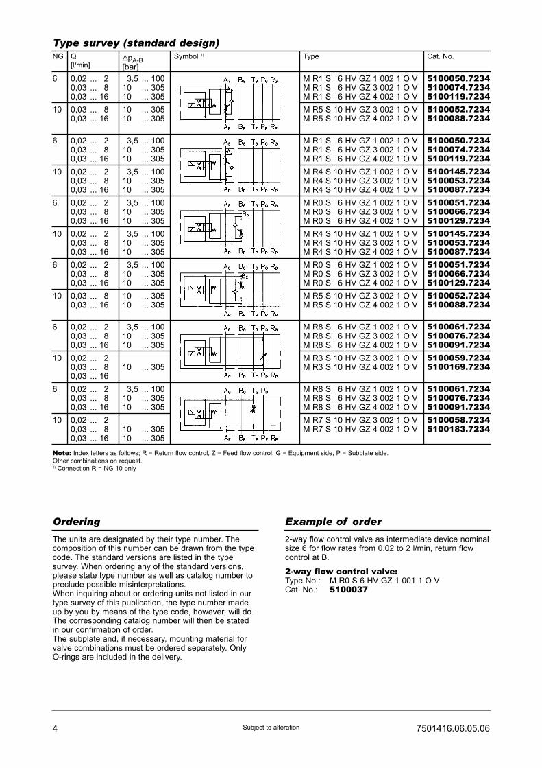
4 7501416.06.05.06Subject to alteration
Ordering Example of order
The units are designated by their type number. Thecomposition of this number can be drawn from the typecode. The standard versions are listed in the typesurvey. When ordering any of the standard versions,please state type number as well as catalog number topreclude possible misinterpretations.When inquiring about or ordering units not listed in ourtype survey of this publication, the type number madeup by you by means of the type code, however, will do.The corresponding catalog number will then be statedin our confirmation of order.The subplate and, if necessary, mounting material forvalve combinations must be ordered separately. OnlyO-rings are included in the delivery.
2-way flow control valve as intermediate device nominalsize 6 for flow rates from 0.02 to 2 l/min, return flowcontrol at B.
2-way flow control valve:Type No.: M R0 S 6 HV GZ 1 001 1 O VCat. No.: 5100037
Type survey (standard design)NG Q
[l/min]VpA-B[bar]
Symbol 1) Type Cat. No.
6 0,02 ... 120,03 ... 180,03 ... 16
13,5 ... 10010 ... 30510 ... 305
M R1 S 16 HV GZ 1 002 1 O VM R1 S 16 HV GZ 3 002 1 O VM R1 S 16 HV GZ 4 002 1 O V
5100050.72345100074.72345100119.7234
6 0,02 ... 120,03 ... 180,03 ... 16
13,5 ... 10010 ... 30510 ... 305
M R1 S 16 HV GZ 1 002 1 O VM R1 S 16 HV GZ 3 002 1 O VM R1 S 16 HV GZ 4 002 1 O V
5100050.72345100074.72345100119.7234
6 0,02 ... 120,03 ... 180,03 ... 16
13,5 ... 10010 ... 30510 ... 305
M R0 S 16 HV GZ 1 002 1 O VM R0 S 16 HV GZ 3 002 1 O VM R0 S 16 HV GZ 4 002 1 O V
5100051.72345100066.72345100129.7234
6 0,02 ... 120,03 ... 180,03 ... 16
13,5 ... 10010 ... 30510 ... 305
M R0 S 16 HV GZ 1 002 1 O VM R0 S 16 HV GZ 3 002 1 O VM R0 S 16 HV GZ 4 002 1 O V
5100051.72345100066.72345100129.7234
6 0,02 ... 120,03 ... 180,03 ... 16
13,5 ... 10010 ... 30510 ... 305
M R8 S 16 HV GZ 1 002 1 O VM R8 S 16 HV GZ 3 002 1 O VM R8 S 16 HV GZ 4 002 1 O V
5100061.72345100076.72345100091.7234
6 0,02 ... 120,03 ... 180,03 ... 16
13,5 ... 10010 ... 30510 ... 305
M R8 S 16 HV GZ 1 002 1 O VM R8 S 16 HV GZ 3 002 1 O VM R8 S 16 HV GZ 4 002 1 O V
5100061.72345100076.72345100091.7234
10 0,03 ... 180,03 ... 16
10 ... 30510 ... 305
M R5 S 10 HV GZ 3 002 1 O VM R5 S 10 HV GZ 4 002 1 O V
5100052.72345100088.7234
10 0,02 ... 120,03 ... 180,03 ... 16
13,5 ... 10010 ... 30510 ... 305
M R4 S 10 HV GZ 1 002 1 O VM R4 S 10 HV GZ 3 002 1 O VM R4 S 10 HV GZ 4 002 1 O V
5100145.72345100053.72345100087.7234
10 0,02 ... 120,03 ... 180,03 ... 16
13,5 ... 10010 ... 30510 ... 305
M R4 S 10 HV GZ 1 002 1 O VM R4 S 10 HV GZ 3 002 1 O VM R4 S 10 HV GZ 4 002 1 O V
5100145.72345100053.72345100087.7234
10 0,03 ... 180,03 ... 16
10 ... 30510 ... 305
M R5 S 10 HV GZ 3 002 1 O VM R5 S 10 HV GZ 4 002 1 O V
5100052.72345100088.7234
10 0,02 ... 120,03 ... 180,03 ... 16
110 ... 305
M R3 S 10 HV GZ 3 002 1 O VM R3 S 10 HV GZ 4 002 1 O V
5100059.72345100169.7234
10 0,02 ... 120,03 ... 180,03 ... 16
110 ... 30510 ... 305
M R7 S 10 HV GZ 3 002 1 O VM R7 S 10 HV GZ 4 002 1 O V
5100058.72345100183.7234
Note: Index letters as follows; R = Return flow control, Z = Feed flow control, G = Equipment side, P = Subplate side.
Other combinations on request.1) Connection R = NG 10 only

57501416.06.05.06 Subject to alteration
Dimensional and spare parts drawings for nominal size 6
M R1 S 6 ... 001M R8 S 6 ... 001
M R0 S 6 ... 001
M R2 S 6 ... 001
Interface to DIN
24340 and ISO
nominal size 6

6 7501416.06.05.06Subject to alteration
Dimensional and spare parts drawings for nominal size 6
M R1 S 6 ... 002
M R8 S 6 ... 002
M R0 S 6 ... 002
ap
pro
x.
10
6 (
co
de
00
2)
ap
pro
x.
10
9 (
co
de
00
4)
appro
x.
106 (
code 0
02)
appro
x.
109 (
code 0
04)
approx. 339
approx. 336
Plug can be
repositioned in steps
of 90o.
Plug can be
repositioned in steps
of 90o.
Plug can be
repositioned in steps
of 90o.
approx. 339
approx. 214
approx. 158
appro
x.
109 (
code 0
04)
appro
x.
106 (
code 0
02)
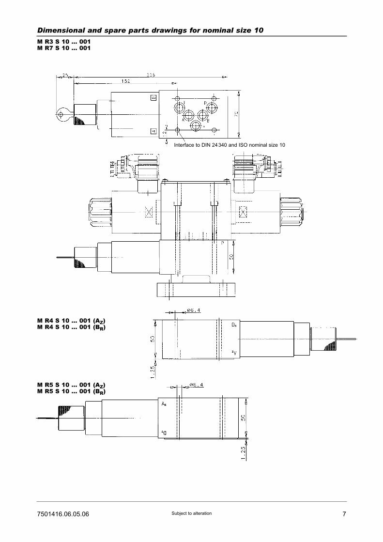
77501416.06.05.06 Subject to alteration
Dimensional and spare parts drawings for nominal size 10
M R3 S 10 ... 001M R7 S 10 ... 001
M R4 S 10 ... 001 (AZ)M R4 S 10 ... 001 (BR)
M R5 S 10 ... 001 (AZ)M R5 S 10 ... 001 (BR)
Interface to DIN 24340 and ISO nominal size 10

8 7501416.06.05.06Subject to alteration
Spare parts (Number of pieces)
Part
1
2
2
3
Flow control valve M R6
see 7500990
O-ring (9.2 x 1.8)
O-ring (12.4 x 1.8)
Directional control valve, nominal size 6,
Cat. No. 5204085.7234see 7501295
1
4
-
1
-
5
-072655807017980701623ETS0615057
1 set of wear parts (for nominal sizes 6 and 10), consisting of part 2. These wear parts are not available separately.
Designation Nominal size 6 Nominal size 10 Cat. No.
Dimensional and spare parts drawings for nominal size 10
M R2 S 10 ... 001
M R3 S 10 ... 002M R5 S 10 ... 002 (AR)M R5 S 10 ... 002 (BZ)M R7 S 10 ... 002
M R4 S 10 ... 002 (AZ)M R4 S 10 ... 002 (BR)
Plug can be
repositioned in steps
of 90o.
ap
pro
x.
97
(co
de
00
2)
ap
pro
x.
10
0 (
co
de
00
4)
Interface to DIN 24340 and ISO nominal size 10
Anschluss R bei MR7S10 ...
002 nicht durchgebohrt

SurveyPressure valves
7501427.06.01.07
Pressure relief valve
Picture/Symbol/Designation Actuation Size Flow max.[l/min]
Line connection Operatingpressure rangemax. [bar]
For furtherinformationsee script
HERION Systemtechnik GmbHUntere Talstraße 65
D-71263 Weil der Stadt-Merklingen
Tel.: +49 (0) 70 33/30 18-0
Fax: +49 (0) 70 33/30 18-10
www.herion-systemtechnik.de
direct operated
Seat valve
(suitable for use asremote pilot valve)
1610
140100
screw-in design
Threadedconnection
mounting plate,interface to DIN24340 and ISO6264
315 75014007501410
Proportional-Pressure relief valve
direct operated
Seat valve
(suitable for use asremote pilot valve)
6 3 mounting plate,interface to DIN24340 and ISO6264
315 7501247
Proportional-Pressure relief valve
direct operated
Seat valve
with damping
1610
5070
mounting plate,interface to DIN24340 and ISO6264
315 7501489
Pressure relief valve pilot operated
Seat valve
102532
100400800
mounting plate,interface to DIN24340 and ISO6264
315 7501401

2 7501427.06.01.07Subject to alteration
Picture/Symbol/Designation Actuation Size Flow max.[l/min]
Line connection Operatingpressure rangemax. [bar]
For furtherinformationsee script
Pressure relief valve electromagneticallyrelease
pilot operated
Seat valve
102532
100400800
mounting plate,interface to DIN24340 and ISO6264
315 7501402
1025
100400
mounting plate,interface to DIN24340 and ISO6264
315 7501248Proportional-Pressure relief valve
pilot operated
Seat valve
Pressure reducing valve 2-way
pilot operated
102532
140150360
mounting plate,interface to DIN24340 and ISO5781
315 7501407
Pressure reducing valve 3-way
pilot operated
6 40 mounting plate,interface to DIN24340 and ISO5781
315 7502831

37501427.06.01.07 Subject to alteration
Picture/Symbol/Designation Actuation Size Flow max.[l/min]
Line connection Operatingpressure rangemax. [bar]
For furtherinformationsee script
Proportional-Pressure reducing valve
3-way
pilot operated
6 40 mounting plate,interface to DIN24340 and ISO5781
315 7502263
10 70 mounting plate,interface toHERION
315 7501409Pressure reducing valve 3-way
pilot operated
Proportional-Pressure reducing valve
3-way
pilot operated
10 70 mounting plate,interface toHERION
315 7501249
Pressure reducing valve 3-way
pilot operated
pneumaticaloperated
10 70 mounting plate,interface toHERION
315 7502517
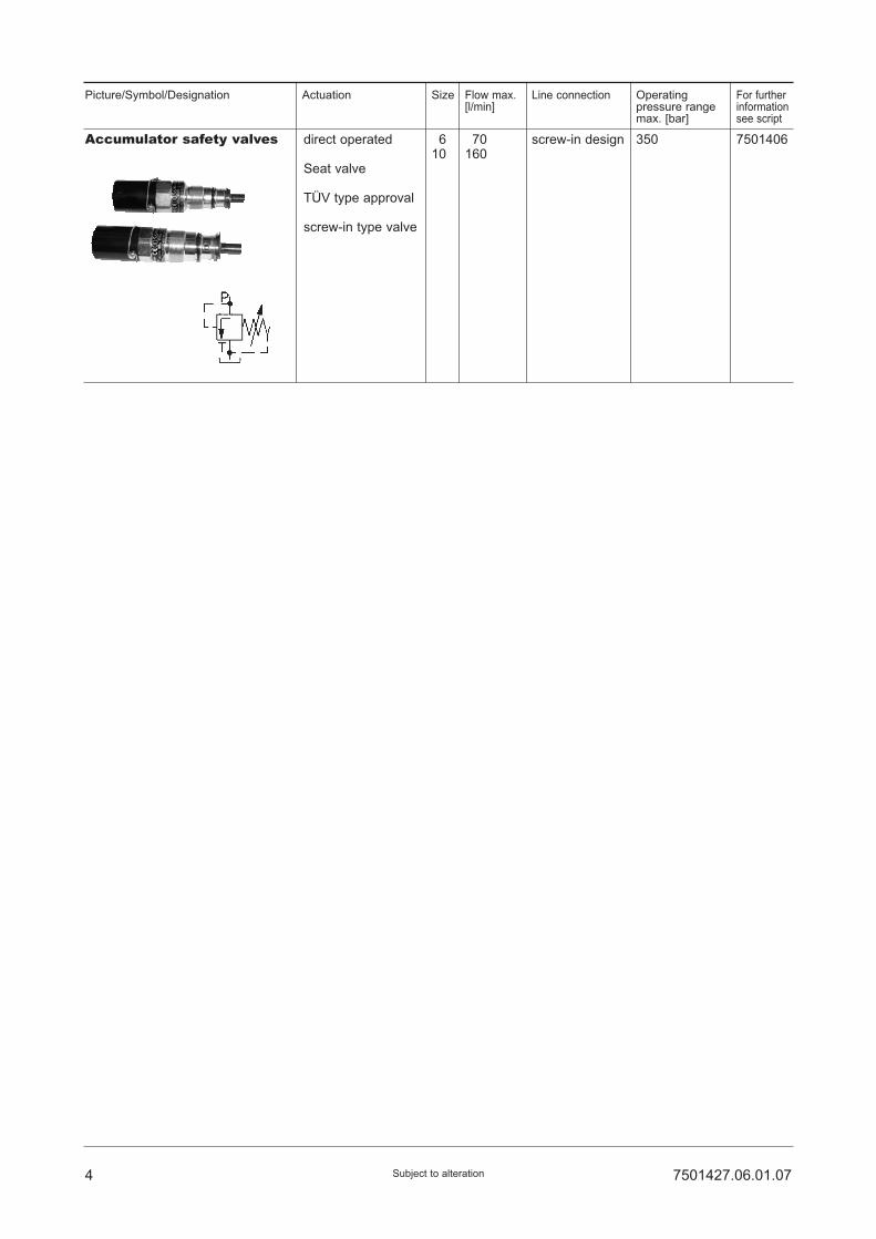
4 7501427.06.01.07Subject to alteration
Picture/Symbol/Designation Actuation Size Flow max.[l/min]
Line connection Operatingpressure rangemax. [bar]
For furtherinformationsee script
Accumulator safety valves direct operated
Seat valve
TÜV type approval
screw-in type valve
1610
170160
screw-in design 350 7501406

SurveyDirectional control valves
7501428.06.02.07
Picture/Symbol/Designation Actuation Size Flow max.[l/min]
Line connection Operatingpressure rangemax. [bar]
For furtherinformationsee script
Notes
HERION Systemtechnik GmbHUntere Talstraße 65
D-71263 Weil der Stadt-Merklingen
Tel.: +49 (0) 70 33/30 18-0
Fax: +49 (0) 70 33/30 18-10
www.herion-systemtechnik.de
direct operated
solenoidoperated
6 40 Subplate,interface to DIN24340 and ISO4401
315 vertical,flangemounted
7501295
direct operated
solenoidoperated
6 45 Port size G 3/8internal threadto DIN ISO228/1
315 - 7501293
direct operated
solenoidoperated
1610
180120
Subplate,interface to DIN24340 and ISO4401
315 - 75032917503292
direct operated
solenoidoperated
6 80 Subplate,interface to DIN24340 and ISO4401
315 withinductiveswitchingpositionmonitoring12 to 24 V
7501294
direct operated
hydraulically,pneumatically
roller leverhand lever
1610
180120
Subplate,interface to DIN24340 and ISO4401
315315
- 75033127503313
Directional control spool type valves
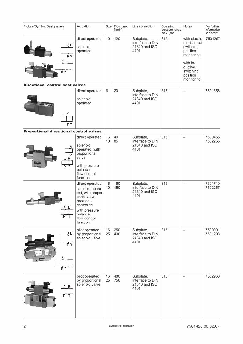
2 7501428.06.02.07Subject to alteration
Picture/Symbol/Designation Actuation Size Flow max.[l/min]
Line connection Operatingpressure rangemax. [bar]
For furtherinformationsee script
Notes
direct operated
solenoidoperated
10 120 Subplate,interface to DIN24340 and ISO4401
315 7501297
direct operated
solenoidoperated, withproportionalvalve
with pressurebalanceflow controlfunction
1610
4085
Subplate,interface to DIN24340 and ISO4401
315 - 75004557502255
direct operated
solenoid opera-ted, with propor-tional valveposition -controlled
with pressurebalanceflow controlfunction
1610
160150
Subplate,interface to DIN24340 and ISO4401
315 - 75017197502257
pilot operatedby proportionalsolenoid valve
1625
250400
Subplate,interface to DIN24340 and ISO4401
315 - 75009017501298
pilot operatedby proportionalsolenoid valve
1625
480750
Subplate,interface to DIN24340 and ISO4401
315 - 7502968
direct operated
solenoidoperated
6 20 Subplate,interface to DIN24340 and ISO4401
315 - 7501856
Proportional directional control valves
Directional control seat valves
with electro-mechanicalswitchingpositionmonitoring
with in-ductiveswitchingpositionmonitoring

Survey2-way-flow control valves
7501430.06.02.07
2-way-flow control valves
Picture/Symbol/Designation Actuation Size Flow max.[l/min]
Line connection Operatingpressure rangemax. [bar]
For furtherinformationsee script
HERION Systemtechnik GmbHUntere Talstraße 65
D-71263 Weil der Stadt-Merklingen
Tel.: +49 (0) 70 33/30 18-0
Fax: +49 (0) 70 33/30 18-10
www.herion-systemtechnik.de
with jump startsuppression
16 0.02 to 24 Subplate,interface to DIN24340, part 4and ISO 4401
315 7500990
2-way-flow control valves 10 0.2 to 50 Subplate,interface to DIN24340, part 4and ISO 4401
315 7500994
Proportional-control valves 2-way
direct controlled
with electricalposition feedback
with pressurebalance
16 30 Subplate,interface to DIN24340 and ISO4401
210 7502022

ProportionalPressure Relief ValvesSizes 6 and 10Poppet valve, direct actuated, with dampingInterface to DIN 24 340 and ISO 4401
PN [pmax.] = 315 bar 7501489.06.01.06
DesignWith these proportional pressure valves, the pressure isadjusted by means of a variable magnetic force actingon the piston. The direct controlled design consists of asmall seat which is connected with the proportionalsolenoid. The hydraulic pressure can be adjusted byincreasing or decreasing the current I which is fed tothe proportional solenoid, by means of a potentiometerand amplifier.
ApplicationWith hydraulic control circuits there is often the require-ment to influence the current by means of an electricalsignal, e.g. for remote control in order to avoid longhydraulic pipe lines or for program controls where thedifferent pressures are adjusted automatically.These proportional pressure valves are also very oftenused in process-controlled plastics injection mouldingmachines.
MountingThe units are bolted onto subplates and sealed byO-rings.
Line connectionSubplate size 6, interface to DIN 24 340-A 6and ISO 4401-AB-03-4-ASubplate size 10, interface to DIN 24 340-E 10and ISO 6264-AR-06-2-A
• Simple electrical program and remote control• Adjustable transient response
Description (standard units)
Features
Type key
D B C ... UP G ... ... ... O ...1 2 3 4 5
Subplate size 6Proportional pressure relief valvesP S 6 G ... ... ... O O
1 2 3
1 Nominal size: 6 - Size 1610 - Size 10
2 Setting pressure: 50 - Up to 150 barrange 99 - Up to 170 bar
90 - Up to 315 bar
3 Code: 002 - Size 16301 - Size 10
4 Engineering version: 3 - Solenoid 7994 2400 mA4 - Size 163 - Size 10
5 Sealing material: O - PerbunanV - Viton
1 Line connection: 200 - G 1/4300 - G 3/8
2 Code: 024 - G 1/4001 - G 3/8
3 Engineering version: 200
Subplate size 10 G 1/2P DB 10 G 4 001 ... O O
1
1 Engineering version: 100
HERION Systemtechnik GmbHUntere Talstraße 65
D-71263 Weil der Stadt-Merklingen
Tel.: +49 (0) 70 33/30 18-0
Fax: +49 (0) 70 33/30 18-10
www.herion-systemtechnik.de
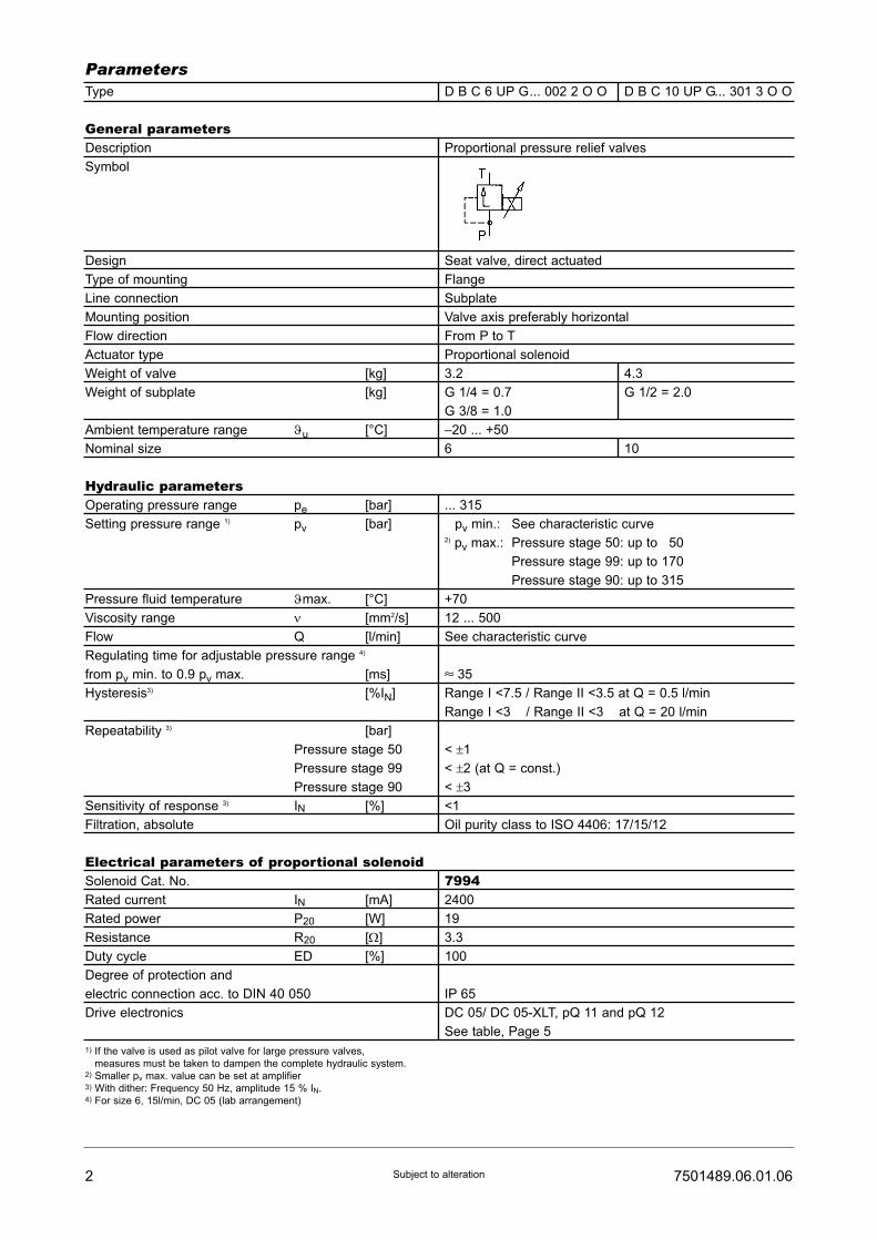
Type D B C 6 UP G... 002 2 O O D B C 10 UP G... 301 3 O O
General parametersDescription Proportional pressure relief valves
Symbol
Design Seat valve, direct actuated
Type of mounting Flange
Line connection Subplate
Mounting position Valve axis preferably horizontal
Flow direction From P to T
Actuator type Proportional solenoid
Weight of valve [kg] 3.2 4.3
Weight of subplate [kg] G 1/4 = 0.7 G 1/2 = 2.0
G 3/8 = 1.0
Ambient temperature range ϑu [°C] –20 ... +50
Nominal size 6 10
Hydraulic parametersOperating pressure range pe [bar] ... 315
Setting pressure range 1) pv [bar] pv min.: See characteristic curve2) pv max.: Pressure stage 50: up to 150
Pressure stage 99: up to 170
Pressure stage 90: up to 315
Pressure fluid temperature ϑmax. [°C] +70
Viscosity range ν [mm2/s] 12 ... 500
Flow Q [l/min] See characteristic curve
Regulating time for adjustable pressure range 4)
from pv min. to 0.9 pv max. [ms] z 35
Hysteresis3) [%IN] Range I <7.5 / Range II <3.5 at Q = 0.5 l/min
Range I <3 / Range II <3 at Q = 20 l/min
Repeatability 3) [bar]
Pressure stage 50 < ±1
Pressure stage 99 < ±2 (at Q = const.)
Pressure stage 90 < ±3
Sensitivity of response 3) IN [%] <1
Filtration, absolute Oil purity class to ISO 4406: 17/15/12
Electrical parameters of proportional solenoidSolenoid Cat. No. 7994Rated current IN [mA] 2400
Rated power P20 [W] 19
Resistance R20 [Ω] 3.3
Duty cycle ED [%] 100
Degree of protection and
electric connection acc. to DIN 40 050 IP 65
Drive electronics DC 05/ DC 05-XLT, pQ 11 and pQ 12
See table, Page 5
1) If the valve is used as pilot valve for large pressure valves,
measures must be taken to dampen the complete hydraulic system.2) Smaller pv max. value can be set at amplifier3) With dither: Frequency 50 Hz, amplitude 15 % IN.4) For size 6, 15l/min, DC 05 (lab arrangement)
2 7501489.06.01.06Subject to alteration
Parameters
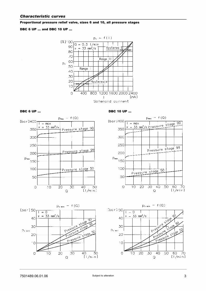
37501489.06.01.06 Subject to alteration
Characteristic curves
Proportional pressure relief valve, sizes 6 and 10, all pressure stages
DBC 6 UP ... and DBC 10 UP ...
DBC 6 UP ... DBC 10 UP ...

4 7501489.06.01.06Subject to alteration
D B C 6 UP G 50 002 4 O O
D B C 6 UP G 99 002 4 O O
D B C 6 UP G 90 002 4 O O
D B C 10 UP G 50 301 3 O O
D B C 10 UP G 99 301 3 O O
D B C 10 UP G 90 301 3 O O
Ordering Example of order
The units are designated by their type number. Thecomposition of this number can be drawn from the typecode. The standard versions are listed in the typesurvey. When ordering any of the standard versions,please state type number as well as catalog number topreclude possible misinterpretations.When inquiring about or ordering units not listed in ourtype survey of this publication, the type number madeup by you by means of the type code, however, will do.The corresponding catalog number will then be statedin our confirmation of order. O-rings are enclosed withflanged units. The subplate, mounting screws and driveelectronics must be ordered separately.
Electrically adjustable proportional pressure relief valve,size 6, flanged version. Max. setting pressure = 315 bar,with additional subplate and mounting screws. Theelectronic control unit must be ordered separately.
Proportional pressure relief valve:Type: D B C 6 UP G 90 002 4 O OCat No.: 6015983.7994Subplate:Type: P S 6 G 2 024 2 O OCat. No.: 1065173Mounting screws: (4 bolts required)Socket head screw (M 5 x 70 DIN 912-10.9)Cat. No.: 0662315
Type survey (standard versions)Size
6
10
50
170
315
50
170
315
0 ... 2400 mA DC 05, DC 05-XLT,
pQ 11 or pQ 12
(see tables)
Subplate G 1/4
P S 6 G 2 024 2 OO
Cat. No. 1065173
Subplate G 3/8
P S 6 G 3 001 2 OO
Cat. No. 1065183Subplate G 1/2
P DB 10 G 4 001 1 OO
Cat. No. 2852600
6015980.7994
6015999.7994
6015983.7994
6015976.7994
6015998.7994
6015979.7994
pv max.
[bar]Proportional
solenoid current
Drive electronics Line connection Type Cat. No.
P S 6 G 2 024 2 OO
P S 6 G 3 001 2 OO
P DB 10 G 4 001 1 O O
SubplatesSize
6
6
10
G 1/4
G 3/8
G 1/2
DIN 24 340-A 6 and ISO 4401-AB-03-4-A
DIN 24 340-A 6 and ISO 4401-AB-03-4-A
DIN 24 340-E 10 and ISO 6264-AB-06-2-A
1065173
1065183
2852600
Port size Subplate
with interface to
Type Cat. No.

57501489.06.01.06 Subject to alteration
Drive electronicsDrive electronicsDC 05 / DC 05-XLTDigital amplifier with constant current
regulator PWM
Power supply: 18 ... 30 VDC,
incl. residual ripple
Ambient temperature ϑU: 0 ... +50 °C
Weight: 0,4 kg
Mounting position: Upright
Free air circulation must be ensured
Space requirement for installation of
19" card rack: 50 mm
European format: 100 x 160 mm
Type
For proportional directional control valvesRated current IN : 0 ... 1600 mA
7503503
7503504
Setpoint input
(switchable)
Internal
setpoints
Pcs.
Ramps
Pcs.
Terminal
strip
Form F
DIN 41612
Number
of pins
PID controller
for external
control loops
Cat. No. For Further
information,
see
script
44
4 2
48
48
51500001)
51500011)
� /�
(switchable)
�
DC 05 2 x 0...±10V
0...±10V
0(4)...20 mA
DC 05-XLT
[V] [mA]
Functional
compatible to
pQ 03
Drive electronics pQ 11Plug-in amplifier with constant current
regulator PWM
Degree of protection: IP 65
Power supply: 18 ... 32 VDC,
Residual ripple: ≤10 %
Ambient temperature ϑU: -20 ...+50 °C
Mounting position: Optional
Setpoint input
(switchable)
For proportional valves with 2 solenoids 2 pQ 11 necessaryRated current IN: 0 ... 2400 mA, allowed resistance of solenoid R20: 2,5...4,5 Ω
HERION
7502961
[mA][V]
Type of connection
Connecting
cable, 2 m
Connector acc. to
DIN 43651
Weight
[kg]
Cat. No. For Further
information,
see
script
0 ... 10
0 ... 10
0 (4)...20
0 (4)...20
�
�
�
�
5980085
59800811)
0,18
0,18
Mark in table: � without, � with1) Cable connector to be ordered separately. Cat. No. 0660689
1) Pre-parametrred electronics on request.
Drive electronics pQ 12Amplifier module with constant current
regulator PWM
Degree of protection: IP 65
Power supply: 18 ... 32 VDC,
Residual ripple: ≤10 %
Ambient temperature ϑU: -20 ...+50 °C
Mounting position: Optional
For attachment on mounting rail acc.
to EN 50022
Setpoint input
(switchable)
For proportional valves with 2 solenoids 2 pQ 11 necessary HERION
7503109
[mA] [mA][V]
Output currents Cat. No. For Furtherinformation,seescript
0 ... 10 0 (4)...20 0 ... 1600 / 2400 5980126

6 7501489.06.01.06Subject to alteration
Dimensional drawings [mm]
Size 6
Size 10
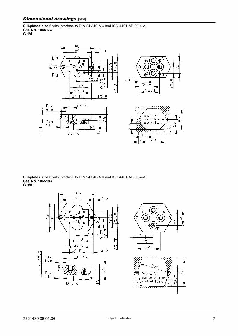
77501489.06.01.06 Subject to alteration
Dimensional drawings [mm]
Subplates size 6 with interface to DIN 24 340-A 6 and ISO 4401-AB-03-4-ACat. No. 1065173G 1/4
Subplates size 6 with interface to DIN 24 340-A 6 and ISO 4401-AB-03-4-ACat. No. 1065183G 3/8

8 7501489.06.01.06Subject to alteration
Dimensional drawings [mm]
Spare parts drawing
Spare parts and mounting screws / Accessories
Part Size
2
2
6
10
2
2
O-ring (9.25 x 1.78)
O-ring (15.6 x 1.78)
0701252
0701256
Qty. Description Cat. No.
Spare partsPart Size
-
-
6
10
4
4
Socket head screw
(M5 x 70 DIN 912-10.9)
Tightening torque MA = 7.6 Nm
Socket head screw
(M12 x 80 DIN 912-10.9)
Tightening torque MA = 110 Nm
0662315
0700479
Qty. Description Cat. No.
Mounting screws1)
1 - 1 Connector 0657859
Accessories
Subplates size 10 with interface to DIN 24 340-E 10 and ISO 6264-AB-06-2-ACat. No. 2852600G 1/2
1) The mounting screws are not included in the delivery
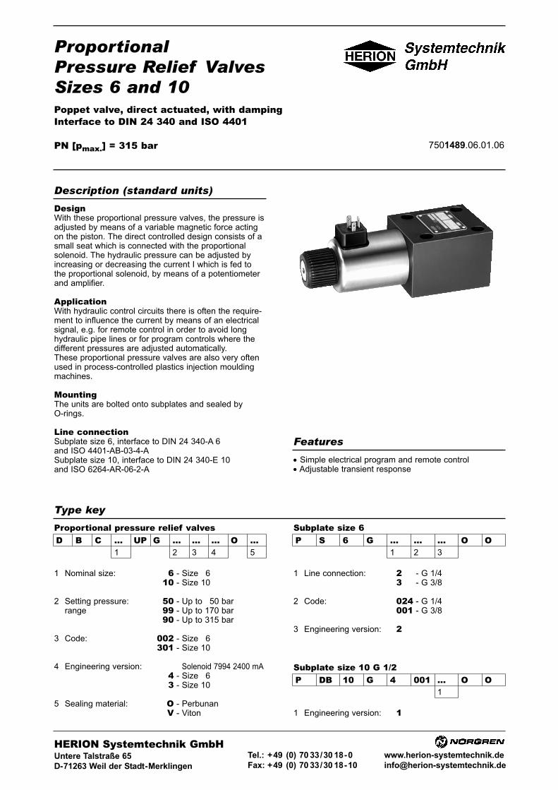
ProportionalPressure Relief ValvesSizes 6 and 10Poppet valve, direct actuated, with dampingInterface to DIN 24 340 and ISO 4401
PN [pmax.] = 315 bar 7501489.06.01.06
DesignWith these proportional pressure valves, the pressure isadjusted by means of a variable magnetic force actingon the piston. The direct controlled design consists of asmall seat which is connected with the proportionalsolenoid. The hydraulic pressure can be adjusted byincreasing or decreasing the current I which is fed tothe proportional solenoid, by means of a potentiometerand amplifier.
ApplicationWith hydraulic control circuits there is often the require-ment to influence the current by means of an electricalsignal, e.g. for remote control in order to avoid longhydraulic pipe lines or for program controls where thedifferent pressures are adjusted automatically.These proportional pressure valves are also very oftenused in process-controlled plastics injection mouldingmachines.
MountingThe units are bolted onto subplates and sealed byO-rings.
Line connectionSubplate size 6, interface to DIN 24 340-A 6and ISO 4401-AB-03-4-ASubplate size 10, interface to DIN 24 340-E 10and ISO 6264-AR-06-2-A
• Simple electrical program and remote control• Adjustable transient response
Description (standard units)
Features
Type key
D B C ... UP G ... ... ... O ...1 2 3 4 5
Subplate size 6Proportional pressure relief valvesP S 6 G ... ... ... O O
1 2 3
1 Nominal size: 6 - Size 1610 - Size 10
2 Setting pressure: 50 - Up to 150 barrange 99 - Up to 170 bar
90 - Up to 315 bar
3 Code: 002 - Size 16301 - Size 10
4 Engineering version: 3 - Solenoid 7994 2400 mA4 - Size 163 - Size 10
5 Sealing material: O - PerbunanV - Viton
1 Line connection: 200 - G 1/4300 - G 3/8
2 Code: 024 - G 1/4001 - G 3/8
3 Engineering version: 200
Subplate size 10 G 1/2P DB 10 G 4 001 ... O O
1
1 Engineering version: 100
HERION Systemtechnik GmbHUntere Talstraße 65
D-71263 Weil der Stadt-Merklingen
Tel.: +49 (0) 70 33/30 18-0
Fax: +49 (0) 70 33/30 18-10
www.herion-systemtechnik.de

Type D B C 6 UP G... 002 2 O O D B C 10 UP G... 301 3 O O
General parametersDescription Proportional pressure relief valves
Symbol
Design Seat valve, direct actuated
Type of mounting Flange
Line connection Subplate
Mounting position Valve axis preferably horizontal
Flow direction From P to T
Actuator type Proportional solenoid
Weight of valve [kg] 3.2 4.3
Weight of subplate [kg] G 1/4 = 0.7 G 1/2 = 2.0
G 3/8 = 1.0
Ambient temperature range ϑu [°C] –20 ... +50
Nominal size 6 10
Hydraulic parametersOperating pressure range pe [bar] ... 315
Setting pressure range 1) pv [bar] pv min.: See characteristic curve2) pv max.: Pressure stage 50: up to 150
Pressure stage 99: up to 170
Pressure stage 90: up to 315
Pressure fluid temperature ϑmax. [°C] +70
Viscosity range ν [mm2/s] 12 ... 500
Flow Q [l/min] See characteristic curve
Regulating time for adjustable pressure range 4)
from pv min. to 0.9 pv max. [ms] z 35
Hysteresis3) [%IN] Range I <7.5 / Range II <3.5 at Q = 0.5 l/min
Range I <3 / Range II <3 at Q = 20 l/min
Repeatability 3) [bar]
Pressure stage 50 < ±1
Pressure stage 99 < ±2 (at Q = const.)
Pressure stage 90 < ±3
Sensitivity of response 3) IN [%] <1
Filtration, absolute Oil purity class to ISO 4406: 17/15/12
Electrical parameters of proportional solenoidSolenoid Cat. No. 7994Rated current IN [mA] 2400
Rated power P20 [W] 19
Resistance R20 [Ω] 3.3
Duty cycle ED [%] 100
Degree of protection and
electric connection acc. to DIN 40 050 IP 65
Drive electronics DC 05/ DC 05-XLT, pQ 11 and pQ 12
See table, Page 5
1) If the valve is used as pilot valve for large pressure valves,
measures must be taken to dampen the complete hydraulic system.2) Smaller pv max. value can be set at amplifier3) With dither: Frequency 50 Hz, amplitude 15 % IN.4) For size 6, 15l/min, DC 05 (lab arrangement)
2 7501489.06.01.06Subject to alteration
Parameters

37501489.06.01.06 Subject to alteration
Characteristic curves
Proportional pressure relief valve, sizes 6 and 10, all pressure stages
DBC 6 UP ... and DBC 10 UP ...
DBC 6 UP ... DBC 10 UP ...

4 7501489.06.01.06Subject to alteration
D B C 6 UP G 50 002 4 O O
D B C 6 UP G 99 002 4 O O
D B C 6 UP G 90 002 4 O O
D B C 10 UP G 50 301 3 O O
D B C 10 UP G 99 301 3 O O
D B C 10 UP G 90 301 3 O O
Ordering Example of order
The units are designated by their type number. Thecomposition of this number can be drawn from the typecode. The standard versions are listed in the typesurvey. When ordering any of the standard versions,please state type number as well as catalog number topreclude possible misinterpretations.When inquiring about or ordering units not listed in ourtype survey of this publication, the type number madeup by you by means of the type code, however, will do.The corresponding catalog number will then be statedin our confirmation of order. O-rings are enclosed withflanged units. The subplate, mounting screws and driveelectronics must be ordered separately.
Electrically adjustable proportional pressure relief valve,size 6, flanged version. Max. setting pressure = 315 bar,with additional subplate and mounting screws. Theelectronic control unit must be ordered separately.
Proportional pressure relief valve:Type: D B C 6 UP G 90 002 4 O OCat No.: 6015983.7994Subplate:Type: P S 6 G 2 024 2 O OCat. No.: 1065173Mounting screws: (4 bolts required)Socket head screw (M 5 x 70 DIN 912-10.9)Cat. No.: 0662315
Type survey (standard versions)Size
6
10
50
170
315
50
170
315
0 ... 2400 mA DC 05, DC 05-XLT,
pQ 11 or pQ 12
(see tables)
Subplate G 1/4
P S 6 G 2 024 2 OO
Cat. No. 1065173
Subplate G 3/8
P S 6 G 3 001 2 OO
Cat. No. 1065183Subplate G 1/2
P DB 10 G 4 001 1 OO
Cat. No. 2852600
6015980.7994
6015999.7994
6015983.7994
6015976.7994
6015998.7994
6015979.7994
pv max.
[bar]Proportional
solenoid current
Drive electronics Line connection Type Cat. No.
P S 6 G 2 024 2 OO
P S 6 G 3 001 2 OO
P DB 10 G 4 001 1 O O
SubplatesSize
6
6
10
G 1/4
G 3/8
G 1/2
DIN 24 340-A 6 and ISO 4401-AB-03-4-A
DIN 24 340-A 6 and ISO 4401-AB-03-4-A
DIN 24 340-E 10 and ISO 6264-AB-06-2-A
1065173
1065183
2852600
Port size Subplate
with interface to
Type Cat. No.
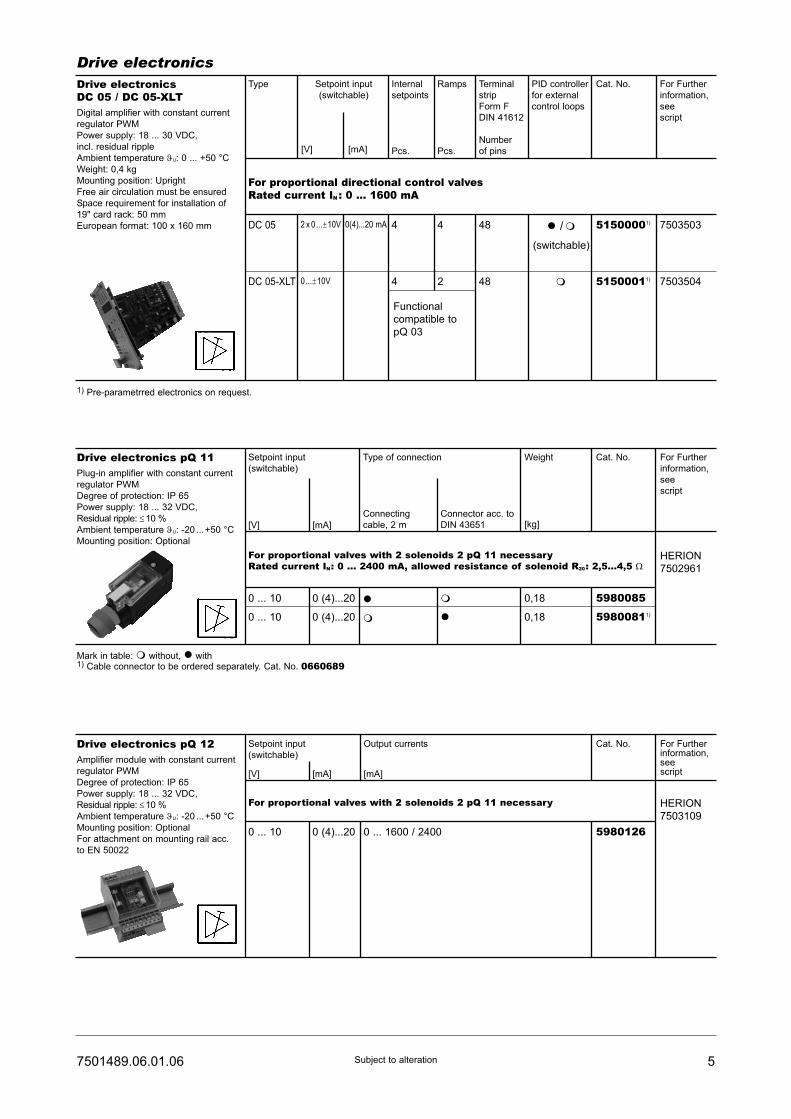
57501489.06.01.06 Subject to alteration
Drive electronicsDrive electronicsDC 05 / DC 05-XLTDigital amplifier with constant current
regulator PWM
Power supply: 18 ... 30 VDC,
incl. residual ripple
Ambient temperature ϑU: 0 ... +50 °C
Weight: 0,4 kg
Mounting position: Upright
Free air circulation must be ensured
Space requirement for installation of
19" card rack: 50 mm
European format: 100 x 160 mm
Type
For proportional directional control valvesRated current IN : 0 ... 1600 mA
7503503
7503504
Setpoint input
(switchable)
Internal
setpoints
Pcs.
Ramps
Pcs.
Terminal
strip
Form F
DIN 41612
Number
of pins
PID controller
for external
control loops
Cat. No. For Further
information,
see
script
44
4 2
48
48
51500001)
51500011)
� /�
(switchable)
�
DC 05 2 x 0...±10V
0...±10V
0(4)...20 mA
DC 05-XLT
[V] [mA]
Functional
compatible to
pQ 03
Drive electronics pQ 11Plug-in amplifier with constant current
regulator PWM
Degree of protection: IP 65
Power supply: 18 ... 32 VDC,
Residual ripple: ≤10 %
Ambient temperature ϑU: -20 ...+50 °C
Mounting position: Optional
Setpoint input
(switchable)
For proportional valves with 2 solenoids 2 pQ 11 necessaryRated current IN: 0 ... 2400 mA, allowed resistance of solenoid R20: 2,5...4,5 Ω
HERION
7502961
[mA][V]
Type of connection
Connecting
cable, 2 m
Connector acc. to
DIN 43651
Weight
[kg]
Cat. No. For Further
information,
see
script
0 ... 10
0 ... 10
0 (4)...20
0 (4)...20
�
�
�
�
5980085
59800811)
0,18
0,18
Mark in table: � without, � with1) Cable connector to be ordered separately. Cat. No. 0660689
1) Pre-parametrred electronics on request.
Drive electronics pQ 12Amplifier module with constant current
regulator PWM
Degree of protection: IP 65
Power supply: 18 ... 32 VDC,
Residual ripple: ≤10 %
Ambient temperature ϑU: -20 ...+50 °C
Mounting position: Optional
For attachment on mounting rail acc.
to EN 50022
Setpoint input
(switchable)
For proportional valves with 2 solenoids 2 pQ 11 necessary HERION
7503109
[mA] [mA][V]
Output currents Cat. No. For Furtherinformation,seescript
0 ... 10 0 (4)...20 0 ... 1600 / 2400 5980126

6 7501489.06.01.06Subject to alteration
Dimensional drawings [mm]
Size 6
Size 10

77501489.06.01.06 Subject to alteration
Dimensional drawings [mm]
Subplates size 6 with interface to DIN 24 340-A 6 and ISO 4401-AB-03-4-ACat. No. 1065173G 1/4
Subplates size 6 with interface to DIN 24 340-A 6 and ISO 4401-AB-03-4-ACat. No. 1065183G 3/8

8 7501489.06.01.06Subject to alteration
Dimensional drawings [mm]
Spare parts drawing
Spare parts and mounting screws / Accessories
Part Size
2
2
6
10
2
2
O-ring (9.25 x 1.78)
O-ring (15.6 x 1.78)
0701252
0701256
Qty. Description Cat. No.
Spare partsPart Size
-
-
6
10
4
4
Socket head screw
(M5 x 70 DIN 912-10.9)
Tightening torque MA = 7.6 Nm
Socket head screw
(M12 x 80 DIN 912-10.9)
Tightening torque MA = 110 Nm
0662315
0700479
Qty. Description Cat. No.
Mounting screws1)
1 - 1 Connector 0657859
Accessories
Subplates size 10 with interface to DIN 24 340-E 10 and ISO 6264-AB-06-2-ACat. No. 2852600G 1/2
1) The mounting screws are not included in the delivery
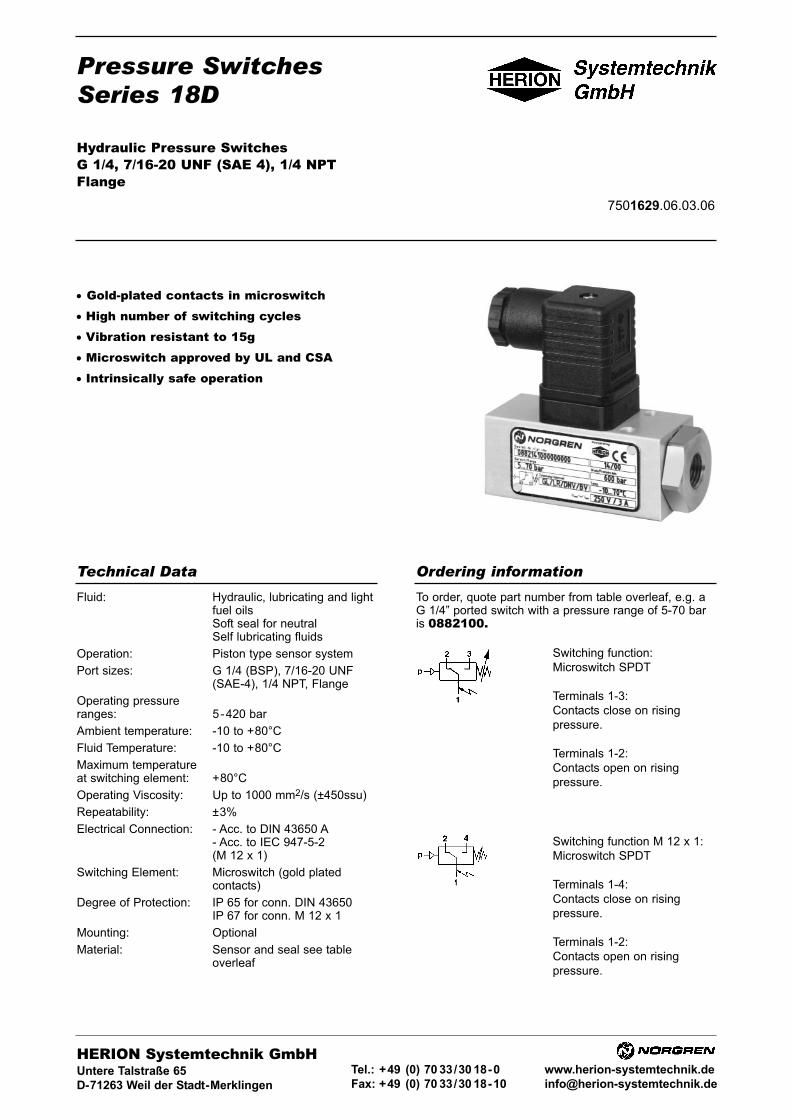
Pressure SwitchesSeries 18D
Hydraulic Pressure SwitchesG 1/4, 7/16-20 UNF (SAE 4), 1/4 NPTFlange
7501629.06.03.06
• Gold-plated contacts in microswitch• High number of switching cycles• Vibration resistant to 15g• Microswitch approved by UL and CSA• Intrinsically safe operation
Fluid: Hydraulic, lubricating and lightfuel oilsSoft seal for neutralSelf lubricating fluids
Operation: Piston type sensor system
Port sizes: G 1/4 (BSP), 7/16-20 UNF(SAE-4), 1/4 NPT, Flange
Operating pressureranges: 5-420 bar
Ambient temperature: -10 to +80°C
Fluid Temperature: -10 to +80°C
Maximum temperatureat switching element: +80°C
Operating Viscosity: Up to 1000 mm2/s (±450ssu)
Repeatability: ±3%
Electrical Connection: - Acc. to DIN 43650 A- Acc. to IEC 947-5-2(M 12 x 1)
Switching Element: Microswitch (gold platedcontacts)
Degree of Protection: IP 65 for conn. DIN 43650IP 67 for conn. M 12 x 1
Mounting: Optional
Material: Sensor and seal see tableoverleaf
Technical Data
To order, quote part number from table overleaf, e.g. aG 1/4” ported switch with a pressure range of 5-70 baris 0882100.
Ordering information
HERION Systemtechnik GmbHUntere Talstraße 65
D-71263 Weil der Stadt-Merklingen
Tel.: +49 (0) 70 33/30 18-0
Fax: +49 (0) 70 33/30 18-10
www.herion-systemtechnik.de
Switching function:
Microswitch SPDT
Terminals 1-3:
Contacts close on rising
pressure.
Terminals 1-2:
Contacts open on rising
pressure.
Switching function M 12 x 1:
Microswitch SPDT
Terminals 1-4:
Contacts close on rising
pressure.
Terminals 1-2:
Contacts open on rising
pressure.
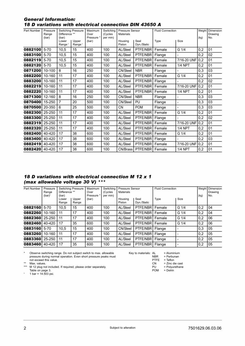
2 7501629.06.03.06Subject to alteration
General Information:18 D variations with electrical connection DIN 43650 APart Number Pressure
Range
(bar)
Switching Pressure
Difference **
(bar)
Lower Upper
Range † Range †
Maximum
Over
Pressure *
(bar)
Switching
(Cycles
per min)
Pressure Sensor
Materials
Housing Seal
Piston Dyn./Static
Fluid Connection
Type Size
Weight
(kg)
Dimension
Drawing
No.
08821000883100088211908821200871200088220008832000882219088222008713000870400087050008823000883300088231908823200882400088340008824190882420
5-70
5-70
5-70
5-70
10-100
10-160
10-160
10-160
10-160
12-160
15-250
20-350
25-250
25-250
25-250
25-250
40-420
40-420
40-420
40-420
10,5
10,5
10,5
10,5
8
11
11
11
11
8
7
6
11
11
11
11
17
17
17
17
15
15
15
15
16
17
17
17
17
16
20
25
17
17
17
17
38
38
38
38
400
400
400
400
250
400
400
400
400
250
500
500
400
400
400
400
600
600
600
600
100
100
100
100
100
100
100
100
100
100
100
100
100
100
100
100
100
100
100
100
AL/Steel
AL/Steel
AL/Steel
AL/Steel
CN/Steel
AL/Steel
AL/Steel
AL/Steel
AL/Steel
CN/Steel
CN/Steel
CN
AL/Steel
AL/Steel
AL/Steel
AL/Steel
AL/Steel
AL/Steel
AL/Steel
CN/Brass
PTFE/NBR
PTFE/NBR
PTFE/NBR
PTFE/NBR
NBR
PTFE/NBR
PTFE/NBR
PTFE/NBR
PTFE/NBR
NBR
PU
POM
PTFE/NBR
PTFE/NBR
PTFE/NBR
PTFE/NBR
PTFE/NBR
PTFE/NBR
PTFE/NBR
PTFE/NBR
Female
Flange
Female
Female
Flange
Female
Flange
Female
Female
Flange
Flange
Flange
Female
Flange
Female
Female
Female
Flange
Female
Female
G 1/4
-
7/16-20 UNF
1/4 NPT
-
G 1/4
-
7/16-20 UNF
1/4 NPT
-
-
-
G 1/4
-
7/16-20 UNF
1/4 NPT
G 1/4
-
7/16-20 UNF
1/4 NPT
0,2
0,2
0,2
0,2
0,3
0,2
0,2
0,2
0,2
0,3
0,3
0,3
0,2
0,2
0,2
0,2
0,2
0,2
0,2
0,2
01
02
01
01
03
01
02
01
01
03
03
03
01
02
01
01
01
03
01
01
Part Number Pressure
Range
(bar)†
Switching Pressure
Difference **
(bar)
Lower Upper
Range Range
Maximum
Over
Pressure *
(bar)
Switching
(Cycles
per min)
Pressure Sensor
Materials
Housing Seal
Piston Dyn./Static
Fluid Connection
Type Size
Weight
(kg)
Dimension
Drawing
No.
08821600882260088236008824600883160088326008833600883460
5-70
10-160
25-250
40-420
5-70
10-160
25-250
40-420
10,5
11
11
17
10,5
11
11
17
15
17
17
35
15
17
17
35
400
400
400
600
400
400
400
600
100
100
100
100
100
100
100
100
AL/Steel
AL/Steel
AL/Steel
AL/Steel
CN/Steel
AL/Steel
AL/Steel
AL/Steel
PTFE/NBR
PTFE/NBR
PTFE/NBR
PTFE/NBR
PTFE/NBR
PTFE/NBR
PTFE/NBR
PTFE/NBR
Female
Female
Female
Female
Flange
Flange
Flange
Flange
G 1/4
G 1/4
G 1/4
G 1/4
-
-
-
-
0,2
0,2
0,2
0,2
0,3
0,2
0,2
0,2
04
04
06
06
05
05
05
05
18 D variations with electrical connection M 12 x 1(max allowable voltage 30 V) ***
* Observe switching range. Do not subject switch to max. allowable
pressure during normal operation. Even short pressure peaks must
not exceed this value.
** Max. values.
*** M 12 plug not included. If required, please order separately.
Table on page 3.† 1 bar = 14.503 psi.
Key to materials: AL = Aluminium
NBR = Perbunan
PTFE = Teflon
CN = Zinc die cast
PU = Polyurethane
POM = Delrin
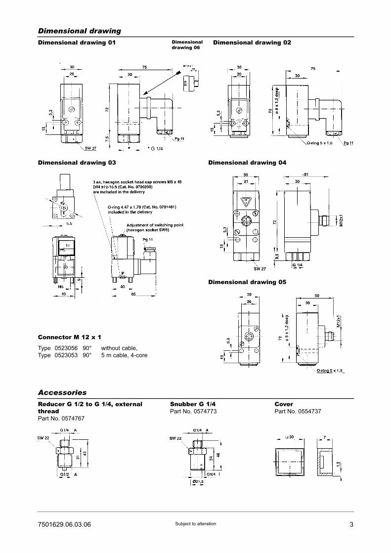
37501629.06.03.06 Subject to alteration
Dimensional drawing
Dimensional drawing 01
Accessories
Reducer G 1/2 to G 1/4, externalthreadPart No. 0574767
Snubber G 1/4Part No. 0574773
CoverPart No. 0554737
Dimensionaldrawing 06
Dimensional drawing 02
Dimensional drawing 03
Connector M 12 x 1
Type 0523056 90° without cable,
Type 0523053 90° 5 m cable, 4-core
Dimensional drawing 04
Dimensional drawing 05
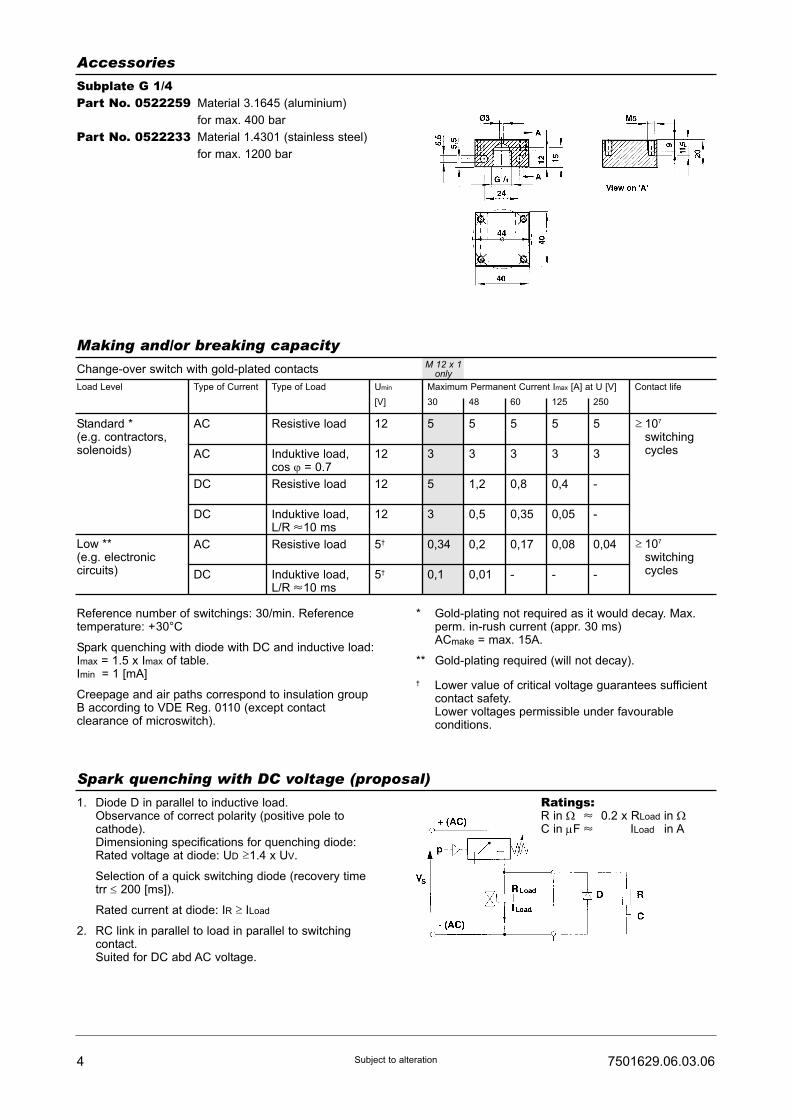
4 7501629.06.03.06Subject to alteration
Accessories
Subplate G 1/4Part No. 0522259 Material 3.1645 (aluminium)
for max. 400 bar
Part No. 0522233 Material 1.4301 (stainless steel)
for max. 1200 bar
Spark quenching with DC voltage (proposal)
1. Diode D in parallel to inductive load.Observance of correct polarity (positive pole tocathode).Dimensioning specifications for quenching diode:Rated voltage at diode: UD 1.4 x UV.
Selection of a quick switching diode (recovery timetrr ≤ 200 [ms]).
Rated current at diode: IR ILoad
2. RC link in parallel to load in parallel to switchingcontact.Suited for DC abd AC voltage.
Making and/or breaking capacity
Change-over switch with gold-plated contacts
Load Level Type of Current Type of Load Umin
[V]
Maximum Permanent Current Imax [A] at U [V]
30 48 60 125 250
Contact life
Standard *(e.g. contractors,solenoids)
Low **(e.g. electroniccircuits)
AC
AC
DC
DC
AC
DC
Resistive load
Induktive load,cos ϕ = 0.7
Resistive load
Induktive load,L/R z10 ms
Resistive load
Induktive load,L/R z10 ms
12
12
12
12
5†
5†
5
3
5
3
0,34
0,1
5
3
1,2
0,5
0,2
0,01
5
3
0,8
0,35
0,17
-
5
3
0,4
0,05
0,08
-
5
3
-
-
0,04
-
≤107
switchingcycles
≤107
switchingcycles
Reference number of switchings: 30/min. Referencetemperature: +30°C
Spark quenching with diode with DC and inductive load:Imax = 1.5 x Imax of table.Imin = 1 [mA]
Creepage and air paths correspond to insulation groupB according to VDE Reg. 0110 (except contactclearance of microswitch).
* Gold-plating not required as it would decay. Max.perm. in-rush current (appr. 30 ms)ACmake = max. 15A.
** Gold-plating required (will not decay).
† Lower value of critical voltage guarantees sufficientcontact safety.Lower voltages permissible under favourableconditions.
M 12 x 1only
≤
≤
Ratings:R in Ω z 0.2 x RLoad in ΩC in μF z ILoad in A
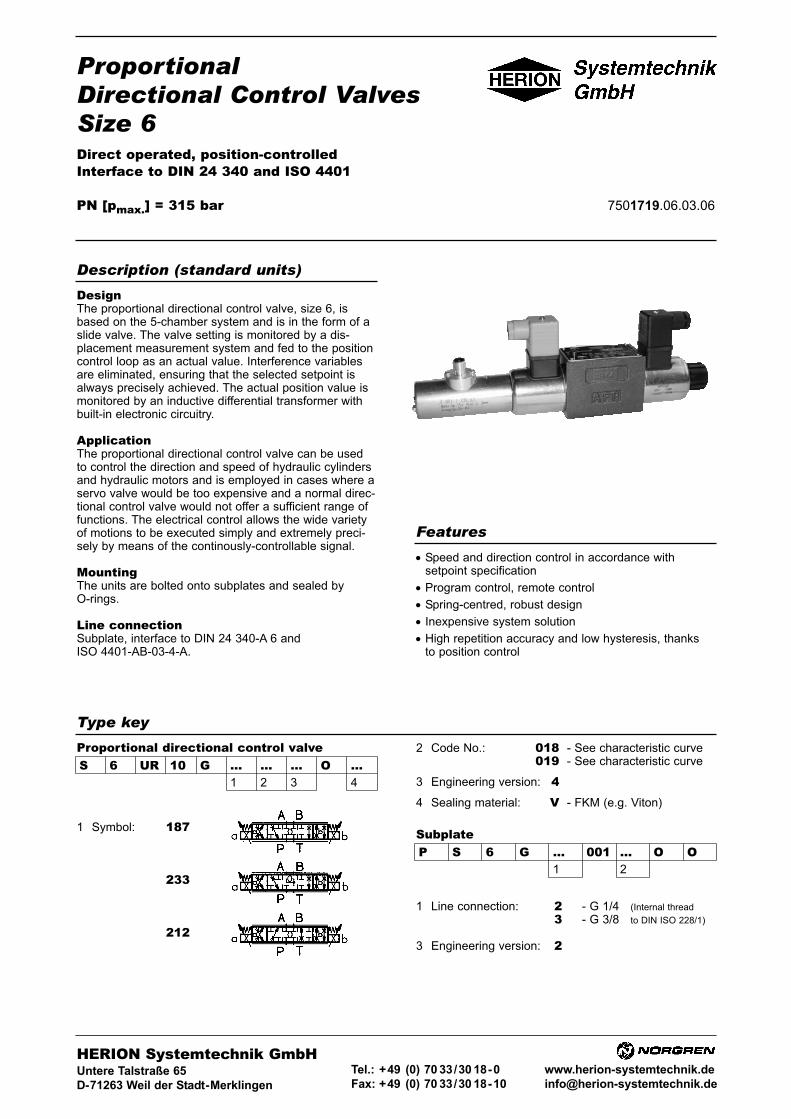
ProportionalDirectional Control ValvesSize 6Direct operated, position-controlledInterface to DIN 24 340 and ISO 4401
PN [pmax.] = 315 bar 7501719.06.03.06
DesignThe proportional directional control valve, size 6, isbased on the 5-chamber system and is in the form of aslide valve. The valve setting is monitored by a dis-placement measurement system and fed to the positioncontrol loop as an actual value. Interference variablesare eliminated, ensuring that the selected setpoint isalways precisely achieved. The actual position value ismonitored by an inductive differential transformer withbuilt-in electronic circuitry.
ApplicationThe proportional directional control valve can be usedto control the direction and speed of hydraulic cylindersand hydraulic motors and is employed in cases where aservo valve would be too expensive and a normal direc-tional control valve would not offer a sufficient range offunctions. The electrical control allows the wide varietyof motions to be executed simply and extremely preci-sely by means of the continously-controllable signal.
MountingThe units are bolted onto subplates and sealed byO-rings.
Line connectionSubplate, interface to DIN 24 340-A 6 andISO 4401-AB-03-4-A.
• Speed and direction control in accordance withsetpoint specification
• Program control, remote control
• Spring-centred, robust design
• Inexpensive system solution
• High repetition accuracy and low hysteresis, thanksto position control
Description (standard units)
Features
Type key
SubplateP S 6 G ... 001 ... O O
1 2
1 Symbol: 187
233
212
1 Line connection: 200 - G 1/4 (Internal thread
300 - G 3/8 to DIN ISO 228/1)
3 Engineering version: 200
HERION Systemtechnik GmbHUntere Talstraße 65
D-71263 Weil der Stadt-Merklingen
Tel.: +49 (0) 70 33/30 18-0
Fax: +49 (0) 70 33/30 18-10
www.herion-systemtechnik.de
S 6 UR 10 G ... ... ... O ...1 2 3 4
Proportional directional control valve 2 Code No.: 018 - See characteristic curve019 - See characteristic curve
3 Engineering version: 44 Sealing material: V - FKM (e.g. Viton)

Type designation S 6 UR ...
General parametersDesignation Proportional directional control valve
Symbol See type survey
Design Spool-type valve, direct operated, position-controlled
Type of mounting Flange
Line connection Subplate
Mounting position Valve axis horizontal (see mounting drawings)
Type of actuator Proportional solenoid, position-controlled
Weight - Valve [kg] 2.8
Weight - Subplate G 1/4 [kg] 1
G 3/8 [kg] 1
Ambient temperataure ϑu [°C] –20 ... +50
Nominal size NG 6
Hydraulic parametersOperating pressure range at P, A and B pmax [bar] up to 315
at T pmax up to 160
Pressure fluid temperature ϑm max. [°C] +70
Viscosity range ν [mm2/s] 12 ... 500
Zero flow (Vp = 100 bar) QL [cm3/min] <30
Max. flow Qmax See characteristic curve
Repeatability 1) [%] <1
Hysteresis 1) [%] <1
Sensitivity of response 1) [%] <0,1
Width of backlash 1) [%] <0,1
Floating time Q = 0%...100% [ms] 30
Q = 100%...0% [ms] 40
Filteration, absolute [μm] 25
Electrical parameters of proportional solenoidRated current IN [mA] 1600
Resistance R20 [Ω] 5.7
Duty cycle ED [%] 100
Electric connection Connector to DIN 43 650 A
Degree of protection to DIN 40 050 IP 65 (with connector)
Drive electronics with module for position control See Page 5
Electrical parameters of displacement sensorSystem Inductive differential transformer with
integrated electronics
Supply voltage [V] 19.2 ... 28.8
Residual ripple <5%
Current consumption max. [mA] 40
Output voltage [V] 7,5 ± 3,9
Temperature range [°C] 0 ... 50
Connection of displacement sensorConnector 4-pin
Cable gland M 12 x 1
Degree of protection to DIN 40 050 IP 65
Connector/Metal 90o Cat. No. 0661748(connector with cable, 2 m) Cat. No. 06818241) referred to max. setpoint U = 10 V
2 7501719.06.03.06Subject to alteration
Parameters

Connecting cable for displacement sensorCable Displacement sensor-Amplifier
Type of cable Screened, 3-core
Cable length max. [m] 75
Cross-section min per core [mm2] 0.5
Resistance max. [Ω/m] 0.05
Capacitance max. Core - core [pF/m] 160
Core - screen [pF/m] 350
Type e.g. LIYCY
37501719.06.03.06 Subject to alteration
Characteristic curves
Valve code 018
Power limit
without pressure
balance
Pressure drop without
pressure balance at
100% opened
Valve code 019
4 VP valve 100 bar
3 VP valve 50 bar
2 Pressure balance
III and VI
1 Pressure balance
II and V
Code 019
Code 018
Valve code 018
Pressure balance II and V Pressure balance III and VI
Setpoint U Setpoint U
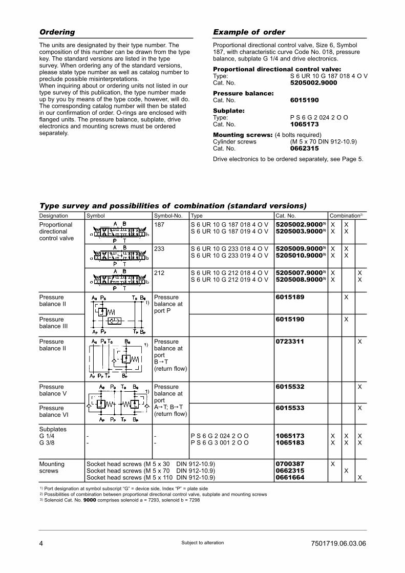
4 7501719.06.03.06Subject to alteration
Ordering Example of order
The units are designated by their type number. Thecomposition of this number can be drawn from the typekey. The standard versions are listed in the typesurvey. When ordering any of the standard versions,please state type number as well as catalog number topreclude possible misinterpretations.When inquiring about or ordering units not listed in ourtype survey of this publication, the type number madeup by you by means of the type code, however, will do.The corresponding catalog number will then be statedin our confirmation of order. O-rings are enclosed withflanged units. The pressure balance, subplate, driveelectronics and mounting screws must be orderedseparately.
Proportional directional control valve, Size 6, Symbol187, with characteristic curve Code No. 018, pressurebalance, subplate G 1/4 and drive electronics.
Proportional directional control valve:Type: S 6 UR 10 G 187 018 4 O VCat. No. 5205002.9000Pressure balance:Cat. No. 6015190Subplate:Type: P S 6 G 2 024 2 O OCat. No. 1065173Mounting screws: (4 bolts required)Cylinder screws (M 5 x 70 DIN 912-10.9)Cat. No. 0662315Drive electronics to be ordered separately, see Page 5.
Type survey and possibilities of combination (standard versions)Designation Symbol Symbol-No. Type Cat. No. Combination2)
Proportionaldirectionalcontrol valve
187
233
212
S 6 UR 10 G 187 018 4 O VS 6 UR 10 G 187 019 4 O V
S 6 UR 10 G 233 018 4 O VS 6 UR 10 G 233 019 4 O V
S 6 UR 10 G 212 018 4 O VS 6 UR 10 G 212 019 4 O V
5205002.90003)
5205003.90003)
5205009.90003)
5205010.90003)
5205007.90003)
5205008.90003)
Pressurebalance atport P
6015189
6015190
0723311
6015532
6015533
10651731065183
P S 6 G 2 024 2 O OP S 6 G 3 001 2 O O
070038706623150661664
Pressurebalance atportB C T(return flow)
Pressurebalance atportAC T; BC T(return flow)
--
--
Pressurebalance II
Pressurebalance III
Pressurebalance II
Pressurebalance V
Pressurebalance VI
SubplatesG 1/4G 3/8
Mountingscrews
Socket head screws (M 5 x 30 DIN 912-10.9)Socket head screws (M 5 x 70 DIN 912-10.9)Socket head screws (M 5 x 110 DIN 912-10.9)
X XX X
X XX X
X XX X
X
X
X
X
X
X X XX X X
XX
X
1) Port designation at symbol subscript “G” = device side, Index “P” = plate side2) Possibilities of combination between proportional directional control valve, subplate and mounting screws3) Solenoid Cat. No. 9000 comprises solenoid a = 7293, solenoid b = 7298

57501719.06.03.06 Subject to alteration
Mounting and dimensional drawings [mm]
Flange-mounting design, horizontal
Proportional directional control valve
S 6 UR 10 G ...
Drive electronicsDrive electronicsDC 05 / DC 05-XLTDigital amplifier with constant current
regulator PWM
Power supply: 18 ... 30 VDC,
incl. residual ripple
Ambient temperature ϑU: 0 ... +50 °C
Weight: 0,4 kg
Mounting position: Upright
Free air circulation must be ensured
Space requirement for installation of
19" card rack: 50 mm
European format: 100 x 160 mm
Type
For proportional directional control valvesRated current IN : 0 ... 1600 mA
7503503
7503504
Setpoint input
(switchable)
Internal
setpoints
Pcs.
Ramps
Pcs.
Terminal
strip
Form F
DIN 41612
Number
of pins
PID controller
for external
control loops
Cat. No. For Further
information,
see
script
44
4 2
48
48
51500001)
51500011)
� /�
(switchable)
�
DC 05 2 x 0...±10V
0...±10V
0(4)...20 mA
DC 05-XLT
[V] [mA]
Functional
compatible to
pQ 03
1) Pre-parametered electronics on request.
Dia
. 36
Dia
. 45 Solenoid “a” Solenoid “a”
Hole pattern S6 to DIN 24340-A6
and ISO 4001
Dia. 9.2
SW 19Tightening torque max. 30 Nm
Approx. 141
Dia. 5.3
78
Approx. 293
Appro
x.
94
46
57
PG 11
Electronic displacement sensor
Connector
Screening
Output 7.5 ± 3.9 V 1
Power supply 24 V 2
Earth 3
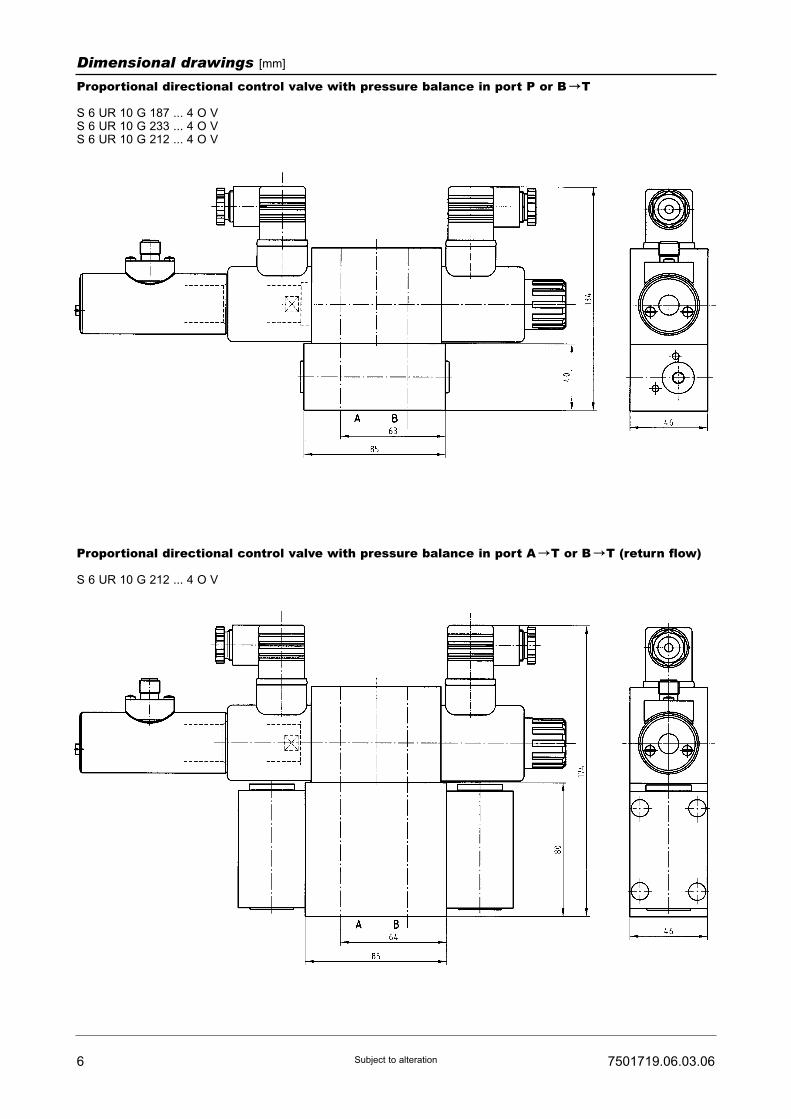
6 7501719.06.03.06Subject to alteration
Dimensional drawings [mm]
Proportional directional control valve with pressure balance in port P or B CT
S 6 UR 10 G 187 ... 4 O VS 6 UR 10 G 233 ... 4 O VS 6 UR 10 G 212 ... 4 O V
Proportional directional control valve with pressure balance in port A CT or B CT (return flow)
S 6 UR 10 G 212 ... 4 O V

77501719.06.03.06 Subject to alteration
Dimensional drawings [mm]
Subplate with interface to DIN 24 340-A6 and ISO 4401-AB-03-4-A
G 1/4
G 3/8
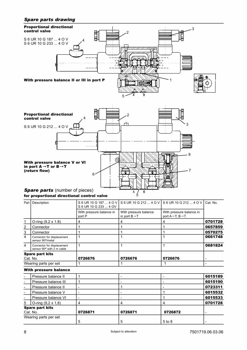
8 7501719.06.03.06Subject to alteration
Spare parts drawing
Spare parts (number of pieces)for proportional directional control valve
Part
1
2
3
4
4
O-ring (9.2 x 1.8)
Connector
Connector
Connector for displacementsensor 90o/metal
Connector for displacementsensor 90o with 2 m cable
4
1
1
1
1
4
1
1
1
1
4
1
1
1
1
0701728065785905702750661748
0681824
-
-
-
-
-
5
Pressure balance II
Pressure balance III
Pressure balance II
Pressure balance V
Pressure balance VI
O-ring (9,2 x 1,8)
1
1
-
-
-
4
-
-
1
-
-
4
-
-
-
1
1
4
601518960151900723311601553260155330701728
Description Cat. No.S 6 UR 10 G 187 ... 4 O V
S 6 UR 10 G 233 ... 4 OV
With pressure balance in
port P
S 6 UR 10 G 212 ... 4 O V
With pressure balance
in port B CT
With pressure balance in
port A CT; B CT
S 6 UR 10 G 212 ... 4 O V
With pressure balance
Proportional directionalcontrol valve
S 6 UR 10 G 187 ... 4 O VS 6 UR 10 G 233 ... 4 O V
With pressure balance II or III in port P
Proportional directionalcontrol valve
S 6 UR 10 G 212 ... 4 O V
With pressure balance V or VIin port A CT or B CT(return flow)
Spare part kitsCat. No.
Wearing parts per set
0726676 07266761 1
07266761
-
-
Spare part kitsCat. No.
Wearing parts per set
0726871 0726871
5 5
0726872
5 to 8
-
-
4
23
1
5
6
5
7
8
3
24
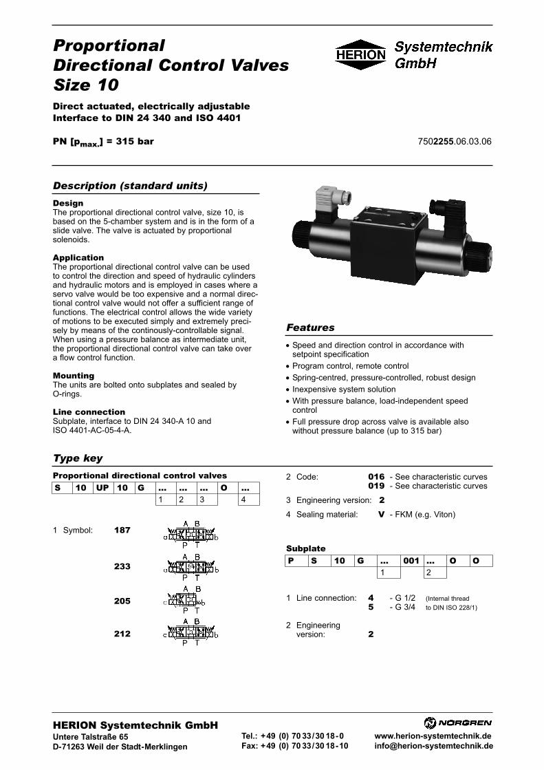
ProportionalDirectional Control ValvesSize 10Direct actuated, electrically adjustableInterface to DIN 24 340 and ISO 4401
PN [pmax.] = 315 bar 7502255.06.03.06
DesignThe proportional directional control valve, size 10, isbased on the 5-chamber system and is in the form of aslide valve. The valve is actuated by proportionalsolenoids.
ApplicationThe proportional directional control valve can be usedto control the direction and speed of hydraulic cylindersand hydraulic motors and is employed in cases where aservo valve would be too expensive and a normal direc-tional control valve would not offer a sufficient range offunctions. The electrical control allows the wide varietyof motions to be executed simply and extremely preci-sely by means of the continously-controllable signal.When using a pressure balance as intermediate unit,the proportional directional control valve can take overa flow control function.
MountingThe units are bolted onto subplates and sealed byO-rings.
Line connectionSubplate, interface to DIN 24 340-A 10 andISO 4401-AC-05-4-A.
• Speed and direction control in accordance withsetpoint specification
• Program control, remote control
• Spring-centred, pressure-controlled, robust design
• Inexpensive system solution
• With pressure balance, load-independent speedcontrol
• Full pressure drop across valve is available alsowithout pressure balance (up to 315 bar)
Description (standard units)
Features
Type key
SubplateP S 10 G ... 001 ... O O
1 2
1 Symbol: 187
233
205
212
1 Line connection: 400 - G 1/2 (Internal thread
500 - G 3/4 to DIN ISO 228/1)
2 Engineeringversion: 200
HERION Systemtechnik GmbHUntere Talstraße 65
D-71263 Weil der Stadt-Merklingen
Tel.: +49 (0) 70 33/30 18-0
Fax: +49 (0) 70 33/30 18-10
www.herion-systemtechnik.de
S 10 UP 10 G ... ... ... O ...1 2 3 4
Proportional directional control valves 2 Code: 016 - See characteristic curves019 - See characteristic curves
3 Engineering version: 24 Sealing material: V - FKM (e.g. Viton)
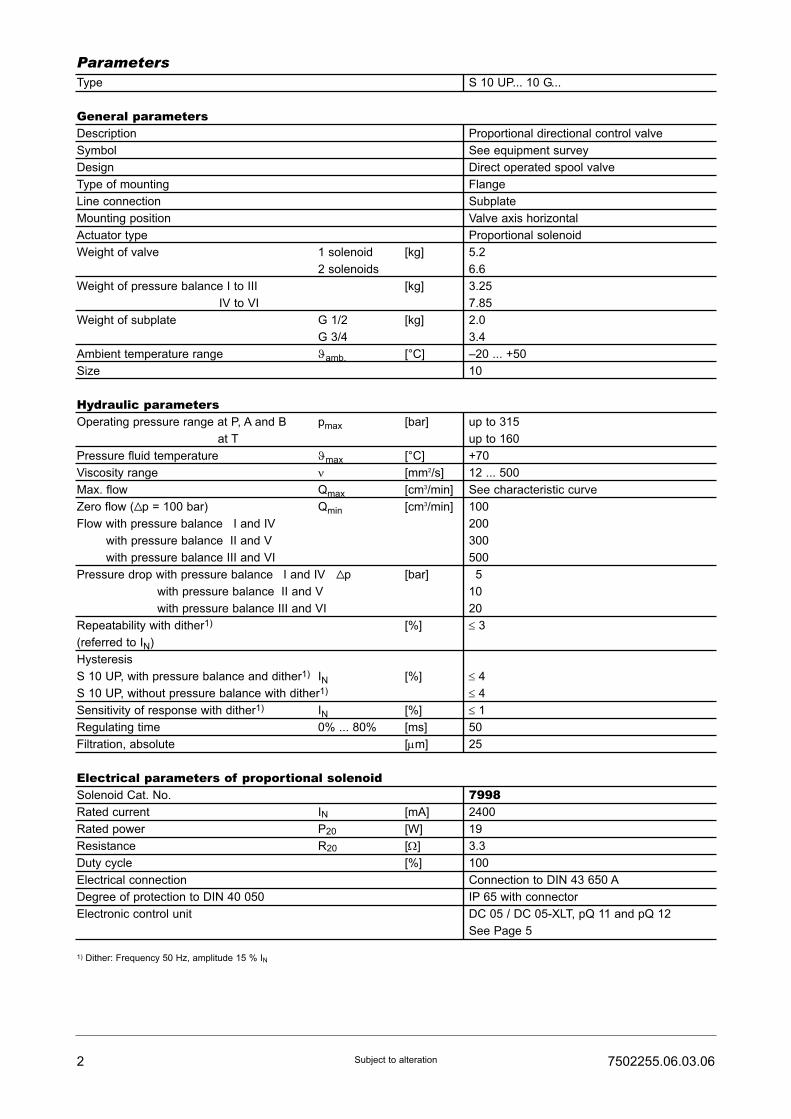
Type S 10 UP... 10 G...
General parametersDescription Proportional directional control valve
Symbol See equipment survey
Design Direct operated spool valve
Type of mounting Flange
Line connection Subplate
Mounting position Valve axis horizontal
Actuator type Proportional solenoid
Weight of valve 1 solenoid [kg] 5.2
2 solenoids 6.6
Weight of pressure balance I to III [kg] 3.25
IV to VI 7.85
Weight of subplate G 1/2 [kg] 2.0
G 3/4 3.4
Ambient temperature range ϑamb. [°C] –20 ... +50
Size 10
Hydraulic parametersOperating pressure range at P, A and B pmax [bar] up to 315
at T up to 160
Pressure fluid temperature ϑmax [°C] +70
Viscosity range ν [mm2/s] 12 ... 500
Max. flow Qmax [cm3/min] See characteristic curve
Zero flow (Vp = 100 bar) Qmin [cm3/min] 100
Flow with pressure balance II and IV 200
with pressure balance III and V 300
with pressure balance III and VI 500
Pressure drop with pressure balance III and IV Vp [bar] 15
with pressure balance III and V 10
with pressure balance III and VI 20
Repeatability with dither1) [%] ≤ 3(referred to IN)
Hysteresis
S 10 UP, with pressure balance and dither1) IN [%] ≤ 4S 10 UP, without pressure balance with dither1) ≤ 4Sensitivity of response with dither1) IN [%] ≤ 1Regulating time 0% ... 80% [ms] 50
Filtration, absolute [μm] 25
Electrical parameters of proportional solenoidSolenoid Cat. No. 7998Rated current IN [mA] 2400
Rated power P20 [W] 19
Resistance R20 [Ω] 3.3
Duty cycle [%] 100
Electrical connection Connection to DIN 43 650 A
Degree of protection to DIN 40 050 IP 65 with connector
Electronic control unit DC 05 / DC 05-XLT, pQ 11 and pQ 12
See Page 5
1) Dither: Frequency 50 Hz, amplitude 15 % IN
2 7502255.06.03.06Subject to alteration
Parameters
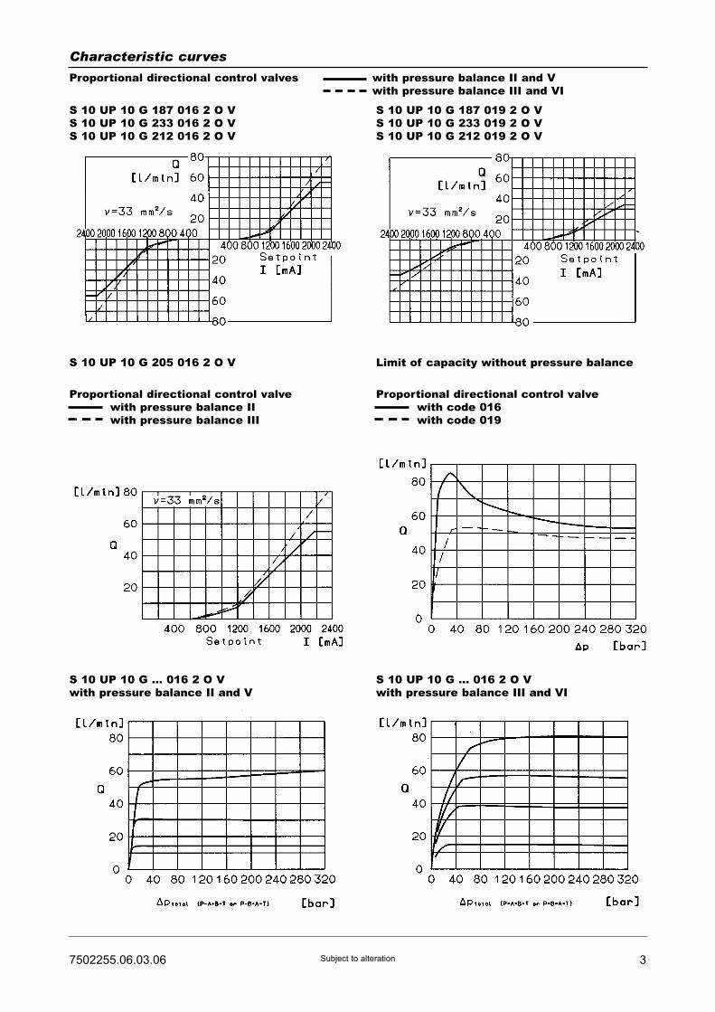
37502255.06.03.06 Subject to alteration
Characteristic curves
Proportional directional control valves with pressure balance II and Vwith pressure balance III and VI
S 10 UP 10 G 187 016 2 O VS 10 UP 10 G 233 016 2 O VS 10 UP 10 G 212 016 2 O V
S 10 UP 10 G 187 019 2 O VS 10 UP 10 G 233 019 2 O VS 10 UP 10 G 212 019 2 O V
Proportional directional control valvewith pressure balance IIwith pressure balance III
Proportional directional control valvewith code 016with code 019
S 10 UP 10 G 205 016 2 O V
S 10 UP 10 G ... 016 2 O Vwith pressure balance II and V
S 10 UP 10 G ... 016 2 O Vwith pressure balance III and VI
Limit of capacity without pressure balance
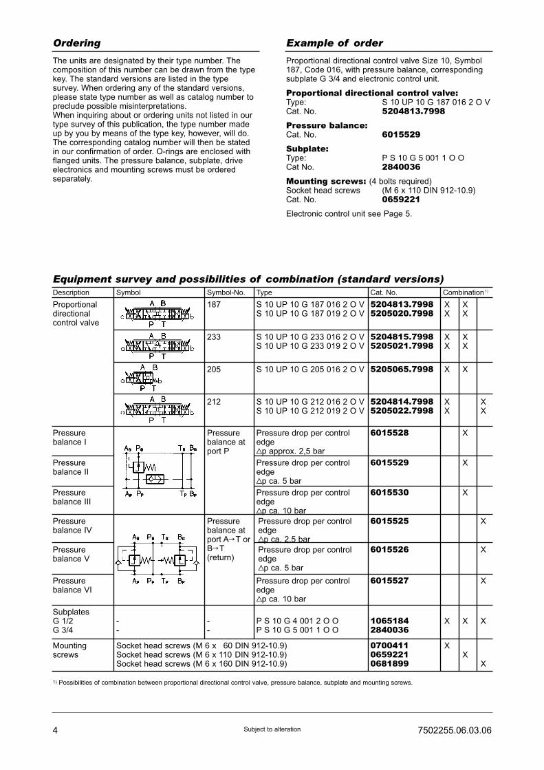
4 7502255.06.03.06Subject to alteration
Ordering Example of order
The units are designated by their type number. Thecomposition of this number can be drawn from the typekey. The standard versions are listed in the typesurvey. When ordering any of the standard versions,please state type number as well as catalog number topreclude possible misinterpretations.When inquiring about or ordering units not listed in ourtype survey of this publication, the type number madeup by you by means of the type key, however, will do.The corresponding catalog number will then be statedin our confirmation of order. O-rings are enclosed withflanged units. The pressure balance, subplate, driveelectronics and mounting screws must be orderedseparately.
Proportional directional control valve Size 10, Symbol187, Code 016, with pressure balance, correspondingsubplate G 3/4 and electronic control unit.
Proportional directional control valve:Type: S 10 UP 10 G 187 016 2 O VCat. No. 5204813.7998Pressure balance:Cat. No. 6015529Subplate:Type: P S 10 G 5 001 1 O OCat No. 2840036Mounting screws: (4 bolts required)Socket head screws (M 6 x 110 DIN 912-10.9)Cat. No. 0659221Electronic control unit see Page 5.
Equipment survey and possibilities of combination (standard versions)Description Symbol Symbol-No. Type Cat. No. Combination 1)
Proportionaldirectionalcontrol valve
187
233
205
212
S 10 UP 10 G 187 016 2 O VS 10 UP 10 G 187 019 2 O V
S 10 UP 10 G 233 016 2 O VS 10 UP 10 G 233 019 2 O V
S 10 UP 10 G 205 016 2 O V
S 10 UP 10 G 212 016 2 O VS 10 UP 10 G 212 019 2 O V
5204813.79985205020.7998
5204815.79985205021.7998
5205065.7998
5204814.79985205022.7998
Pressurebalance atport P
6015528
6015529
6015530
6015525
6015526
6015527
10651842840036
P S 10 G 4 001 2 O OP S 10 G 5 001 1 O O
Pressure drop per controledgeVp approx. 2,5 bar
Pressure drop per controledgeVp ca. 5 bar
Pressure drop per controledgeVp ca. 10 bar
Pressure drop per controledgeVp ca. 2,5 bar
Pressure drop per controledgeVp ca. 5 bar
Pressure drop per controledgeVp ca. 10 bar
070041106592210681899
Pressurebalance atport AC T orBC T(return)
--
--
Pressurebalance I
Pressurebalance II
Pressurebalance III
Pressurebalance IV
Pressurebalance V
Pressurebalance VI
SubplatesG 1/2G 3/4
Mountingscrews
Socket head screws (M 6 x 160 DIN 912-10.9)Socket head screws (M 6 x 110 DIN 912-10.9)Socket head screws (M 6 x 160 DIN 912-10.9)
1) Possibilities of combination between proportional directional control valve, pressure balance, subplate and mounting screws.
X XX X
X XX X
X X
X XX X
X
X
X
X
X
X
X X X
XX
X

57502255.06.03.06 Subject to alteration
Drive electronics
Drive electronicsDC 05 / DC 05-XLTDigital amplifier with constant current
regulator PWM
Power supply: 18 ... 30 VDC,
incl. residual ripple
Ambient temperature ϑU: 0 ... +50 °C
Weight: 0,4 kg
Mounting position: Upright
Free air circulation must be ensured
Space requirement for installation of
19" card rack: 50 mm
European format: 100 x 160 mm
Type
For proportional directional control valvesRated current IN : 0 ... 1600 mA
7503503
7503504
Setpoint input
(switchable)
Internal
setpoints
Pcs.
Ramps
Pcs.
Terminal
strip
Form F
DIN 41612
Number
of pins
PID controller
for external
control loops
Cat. No. For Further
information,
see
script
44
4 2
48
48
51500001)
51500011)
� /�
(switchable)
�
DC 05 2 x 0...±10V
0...±10V
0(4)...20 mA
DC 05-XLT
[V] [mA]
Functional
compatible to
pQ 03
Drive electronics pQ 11Plug-in amplifier with constant current
regulator PWM
Degree of protection: IP 65
Power supply: 18 ... 32 VDC,
Residual ripple: ≤10 %
Ambient temperature ϑU: -20 ...+50 °C
Mounting position: Optional
Setpoint input
(switchable)
For proportional valves with 2 solenoids 2 pQ 11 necessaryRated current IN: 0 ... 2400 mA, allowed resistance of solenoid R20: 2,5...4,5 Ω
HERION
7502961
[mA][V]
Type of connection
Connecting
cable, 2 m
Connector acc. to
DIN 43651
Weight
[kg]
Cat. No. For Further
information,
see
script
0 ... 10
0 ... 10
0 (4)...20
0 (4)...20
�
�
�
�
5980085
59800811)
0,18
0,18
Mark in table: � without, � with1) Cable connector to be ordered separately. Cat. No. 0660689
1) Pre-parametrred electronics on request.
Drive electronics pQ 12Amplifier module with constant current
regulator PWM
Degree of protection: IP 65
Power supply: 18 ... 32 VDC,
Residual ripple: ≤10 %
Ambient temperature ϑU: -20 ...+50 °C
Mounting position: Optional
For attachment on mounting rail acc.
to EN 50022
Setpoint input
(switchable)
For proportional valves with 2 solenoids 2 pQ 11 necessary HERION
7503109
[mA] [mA][V]
Output currents Cat. No. For Furtherinformation,seescript
0 ... 10 0 (4)...20 0 ... 1600 / 2400 5980126
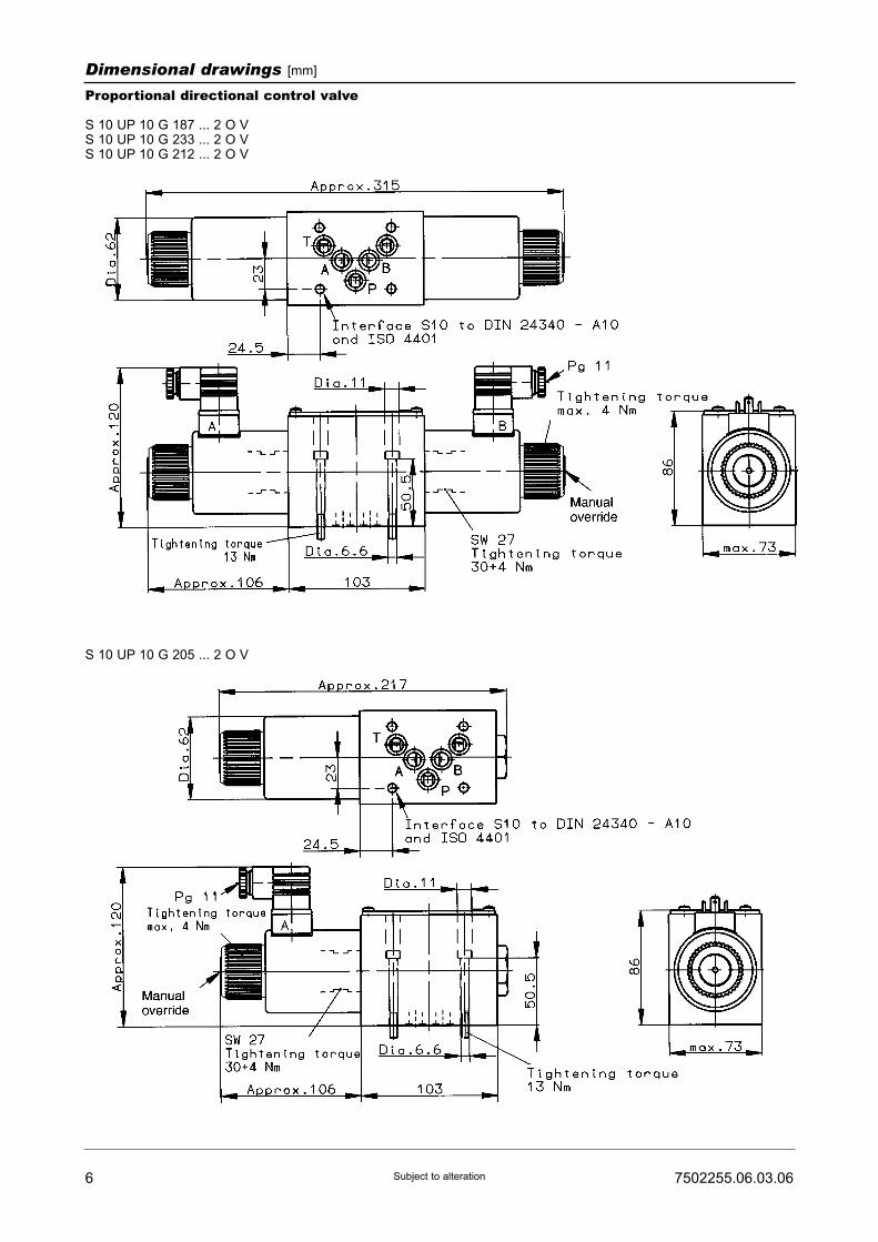
6 7502255.06.03.06Subject to alteration
Dimensional drawings [mm]
Proportional directional control valve
S 10 UP 10 G 187 ... 2 O VS 10 UP 10 G 233 ... 2 O VS 10 UP 10 G 212 ... 2 O V
S 10 UP 10 G 205 ... 2 O V

77502255.06.03.06 Subject to alteration
Dimensional drawings [mm]
Subplate, Size 10 with interface to DIN 24 340-A10 and ISO 4401-AC-05-4-A
Subplate 1Cat. No. 1065184G 1/2
Subplate 2Cat. No. 2840036G 3/4
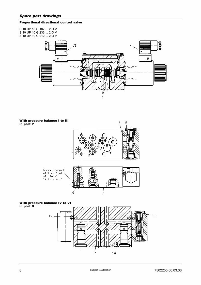
8 7502255.06.03.06Subject to alteration
Spare part drawings
Proportional directional control valve
S 10 UP 10 G 187 ... 2 O VS 10 UP 10 G 233 ... 2 O VS 10 UP 10 G 212 ... 2 O V
With pressure balance I to IIIin port P
With pressure balance IV to VIin port B
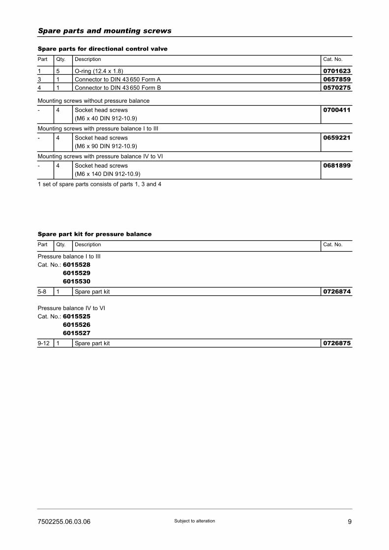
97502255.06.03.06 Subject to alteration
Spare parts and mounting screws
Spare parts for directional control valvePart Qty.
1
3
4
- 4 Socket head screws
(M6 x 40 DIN 912-10.9)
Mounting screws without pressure balance
5
1
1
O-ring (12.4 x 1.8)
Connector to DIN 43 650 Form A
Connector to DIN 43 650 Form B
070162306578590570275
0700411
- 4 Socket head screws
(M6 x 90 DIN 912-10.9)
Mounting screws with pressure balance I to III
0659221
- 4
5-8 1
Socket head screws
(M6 x 140 DIN 912-10.9)
Mounting screws with pressure balance IV to VI
1 set of spare parts consists of parts 1, 3 and 4
0681899
Description Cat. No.
Spare part kit for pressure balancePart Qty.
Pressure balance I to III
Cat. No.: 601552860155296015530
Spare part kit 0726874
9-12 1
Pressure balance IV to VI
Cat. No.: 601552560155266015527
Spare part kit 0726875
Description Cat. No.
10 7502255.06.03.06Subject to alteration
Notes:

ProportionalDirectional Control ValvesSize 10Direct actuated, electrically adjustable, position-controlledInterface to DIN 24 340 and ISO 4401
PN [pmax.] = 315 bar 7502257.06.03.06
DesignThe proportional directional control valve, size 10, isbased on the 5-chamber system and is in the form of aslide valve. The valve is actuated by proportionalsolenoids. The valve setting is monitored by a displace-ment measurement system and fed to the position con-trol loop as an actual value. Interference variables areeliminated, ensuring that the selected setpoint is alwaysprecisely achieved. The actual position value is monito-red by an inductive differential transformer with integra-ted electronic circuitry.
ApplicationThe proportional directional control valve can be usedto control the direction and speed of hydraulic cylindersand hydraulic motors and is employed in cases where aservo valve would be too expensive and a normal direc-tional control valve would not offer a sufficient range offunctions. The electrical control allows the wide varietyof motions to be executed simply and extremely preci-sely by means of the continously-controllable signal.
MountingThe units are bolted onto subplates and sealed byO-rings.
Line connectionSubplate, interface to DIN 24 340-A 10 andISO 4401-AC-05-4-A.
• Speed and direction control in accordance withsetpoint specification
• Program control, remote control
• Spring-centred, robust design
• Inexpensive system solution
• High repetition accuracy and low hysteresis, thanksto position control
• With pressure balance, load-independent speedcontrol
• Full pressure drop across valve is available alsowithout pressure balance (up to 315 bar)
Description (standard units)
Features
Type key
SubplateP S 10 G ... 001 ... O O
1 2
1 Symbol: 187
233
212
1 Line connection: 400 - G 1/2 (Internal thread
500 - G 3/4 to DIN ISO 228/1)
2 Engineering version: 200
HERION Systemtechnik GmbHUntere Talstraße 65
D-71263 Weil der Stadt-Merklingen
Tel.: +49 (0) 70 33/30 18-0
Fax: +49 (0) 70 33/30 18-10
www.herion-systemtechnik.de
S 10 UR 10 G ... ... ... O ...1 2 3 4
Proportional directional control valves 2 Code: 016 - see characteristic curves019 - see characteristic curves
3 Engineering version: 24 Sealing material: V - FKM (e.g. Viton)

Type S 10 UR...
General parametersDescription Proportional directional control valve
Symbol See equipment survey
Design Direct operated spool valve, position-controlled
Type of mounting Flange
Line connection Subplate
Mounting position Valve axis horizontal
Actuator type Proportional solenoid, position-controlled
Weight of valve [kg] 7
Weight of subplate G 1/2 [kg] 2.0
G 3/4 3.4
Ambient temperature range ϑamb [°C] –20 ... +50
Size 10
Hydraulic parametersOperating pressure range at P, A and B pmax [bar] up to 315
at T up to 160
Pressure fluid temperature ϑmax. [°C] +70
Viscosity range ν [mm2/s] 12 ... 500
Max. flow Qmax See characteristic curve
Zero flow (Vp = 100 bar) QL [cm3/min] 100
Repeatability [%] ≤ 1Hysteresis [%] ≤ 1Sensitivity of response [%] ≤ 0.5
Regulating time 0% ... 80% [ms] 45
80% ... 0% [ms] 60
Filtration, absolute [μm] 25
Electrical parameters of proportional solenoidCat. No. solenoid 7998/7999 with displacement sensor
Rated current IN [mA] 2400
Rated power P20 [W] 19
Resistance R20 [Ω] 3.3
Duty cycle [%] 100
Electrical connection Connection to DIN 43 650 A
Degree of protection to DIN DIN 40 050 IP 65 (with connector)
Electrical parameters of displacement sensorSystem Inductive differential transformer
with integrated electronics
Supply voltage [V] 19.2 ... 28.8
Residual ripple [%] <5
Current consumption [mA] <40
Output voltage [V] 7.5 ± 4.5
2 7502257.06.03.06Subject to alteration
Parameters
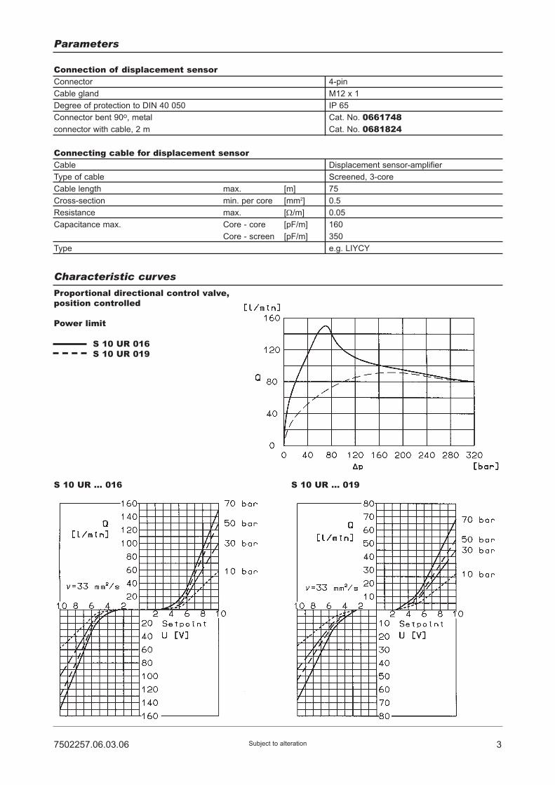
37502257.06.03.06 Subject to alteration
Characteristic curves
Connection of displacement sensorConnector 4-pin
Cable gland M12 x 1
Degree of protection to DIN 40 050 IP 65
Connector bent 90o, metal Cat. No. 0661748connector with cable, 2 m Cat. No. 0681824
Connecting cable for displacement sensorCable Displacement sensor-amplifier
Type of cable Screened, 3-core
Cable length max. [m] 75
Cross-section min. per core [mm2] 0.5
Resistance max. [Ω/m] 0.05
Capacitance max. Core - core [pF/m] 160
Core - screen [pF/m] 350
Type e.g. LIYCY
Parameters
Proportional directional control valve,position controlled
Power limit
S 10 UR 016S 10 UR 019
S 10 UR ... 016 S 10 UR ... 019
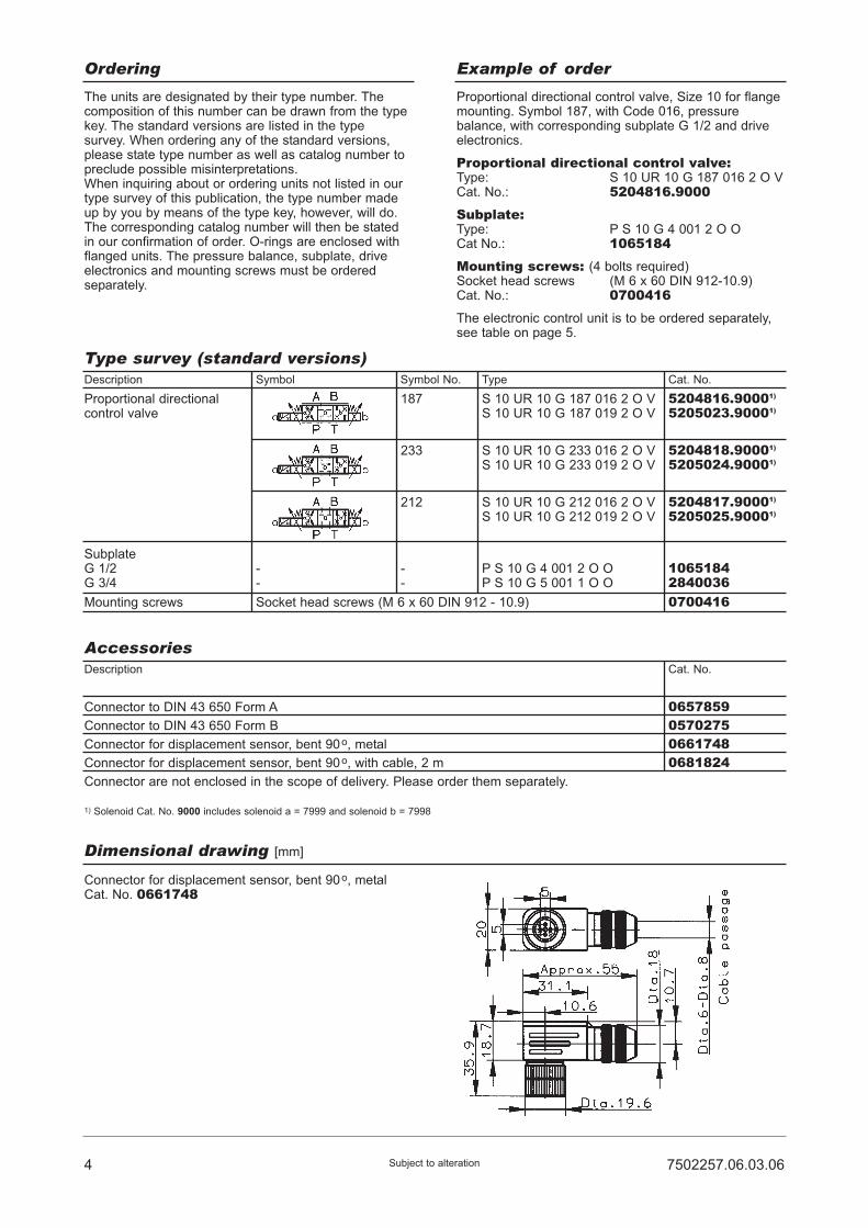
4 7502257.06.03.06Subject to alteration
Ordering Example of order
The units are designated by their type number. Thecomposition of this number can be drawn from the typekey. The standard versions are listed in the typesurvey. When ordering any of the standard versions,please state type number as well as catalog number topreclude possible misinterpretations.When inquiring about or ordering units not listed in ourtype survey of this publication, the type number madeup by you by means of the type key, however, will do.The corresponding catalog number will then be statedin our confirmation of order. O-rings are enclosed withflanged units. The pressure balance, subplate, driveelectronics and mounting screws must be orderedseparately.
Proportional directional control valve, Size 10 for flangemounting. Symbol 187, with Code 016, pressurebalance, with corresponding subplate G 1/2 and driveelectronics.
Proportional directional control valve:Type: S 10 UR 10 G 187 016 2 O VCat. No.: 5204816.9000Subplate:Type: P S 10 G 4 001 2 O OCat No.: 1065184Mounting screws: (4 bolts required)Socket head screws (M 6 x 60 DIN 912-10.9)Cat. No.: 0700416The electronic control unit is to be ordered separately,see table on page 5.
Type survey (standard versions)Description Symbol Symbol No. Type Cat. No.
Proportional directionalcontrol valve
187
233
212
S 10 UR 10 G 187 016 2 O VS 10 UR 10 G 187 019 2 O V
S 10 UR 10 G 233 016 2 O VS 10 UR 10 G 233 019 2 O V
S 10 UR 10 G 212 016 2 O VS 10 UR 10 G 212 019 2 O V
5204816.90001)
5205023.90001)
5204818.90001)
5205024.90001)
5204817.90001)
5205025.90001)
SubplateG 1/2G 3/4
Mounting screws
1) Solenoid Cat. No. 9000 includes solenoid a = 7999 and solenoid b = 7998
--
--
P S 10 G 4 001 2 O OP S 10 G 5 001 1 O O
106518428400360700416Socket head screws (M 6 x 60 DIN 912 - 10.9)
AccessoriesDescription Cat. No.
Connector to DIN 43 650 Form A
Connector to DIN 43 650 Form B
Connector for displacement sensor, bent 90o, metal
Connector for displacement sensor, bent 90o, with cable, 2 m
Connector are not enclosed in the scope of delivery. Please order them separately.
0657859057027506617480681824
Dimensional drawing [mm]
Connector for displacement sensor, bent 90o, metalCat. No. 0661748
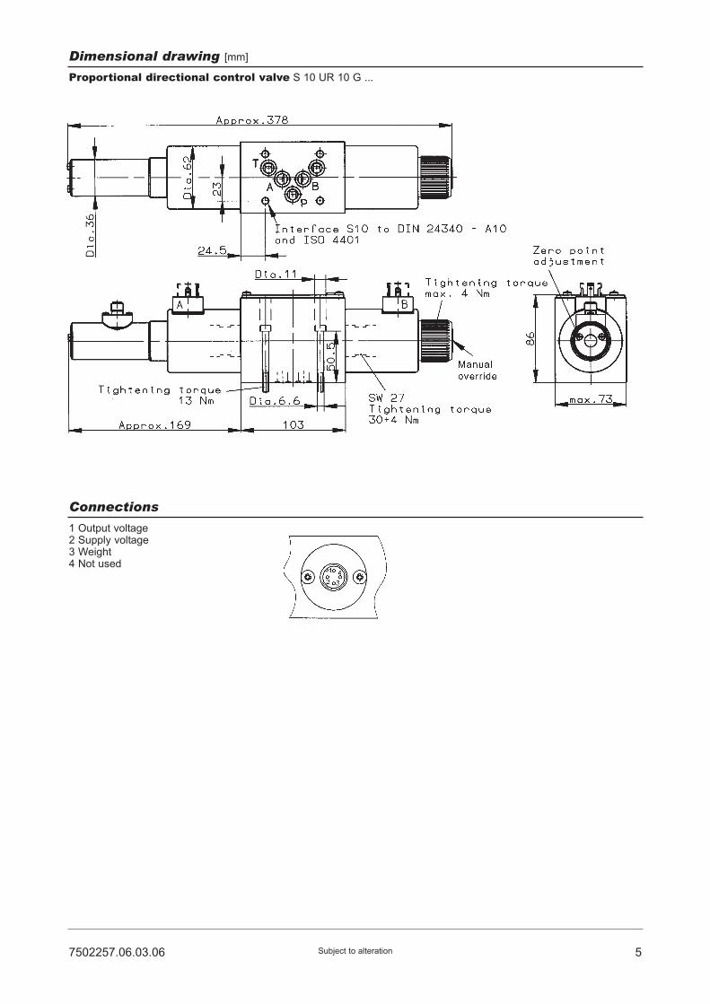
57502257.06.03.06 Subject to alteration
Dimensional drawing [mm]
Connections
Proportional directional control valve S 10 UR 10 G ...
1 Output voltage2 Supply voltage3 Weight4 Not used
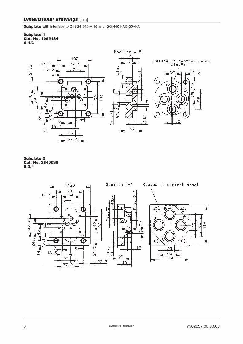
6 7502257.06.03.06Subject to alteration
Dimensional drawings [mm]
Subplate with interface to DIN 24 340-A 10 and ISO 4401-AC-05-4-A
Subplate 1Cat. No. 1065184G 1/2
Subplate 2Cat. No. 2840036G 3/4

77502257.06.03.06 Subject to alteration
Spare part drawing
Proportional directional control valves
S 10 UR 10 G 187 ... 2 O VS 10 UR 10 G 233 ... 2 O VS 10 UR 10 G 212 ... 2 O V
Spare parts and mounting screws / Accessories
Spare parts for directional control valvePart Qty.
1
- 4 Socket head screw
(M6 x 60 DIN 912-10.9)
Mounting screws
5 O-ring (12,4 x 1,8) 0701623
0700416
2
3
4
5
1
1
1
1
Connector to DIN 43 650 Form A
Connector to DIN 43 650 Form B
Connector for displacement sensor, bent 90o, metal
Connector for displacement sensor, bent 90o, with cable, 2 m
Accessories0657859057027506617480681824
Description Cat. No.

8 7502257.06.03.06Subject to alteration
Notes:

Proportional DirectionalControl ValvesNominal sizes 16 and 25Pilot operated, electrically adjustableInterface acc. to DIN 24 340 and ISO 4401
PN [pmax.] = 315 bar 7502968.06.01.06
DesignThe proportional directional control valves, Sizes 16and 25, consist of a hydraulic main stage which isindirectly operated by the hydraulic solenoid actuatedpilot stage mounted on top.The main piston is centered by means of two springs,so the piston is held in mid-position in case of powerfailure or breakdown of the pump pressure.
ApplicationThe proportional directional control valve serves fordirectional or speed control of hydraulic cylinders andhydraulic motors. It is used in cases where a servovalve would be too costly and a conventional directionalcontrol valve would not be sufficient in terms offunctions. A continuously controllable signal enables amost simple and precise remote control of the requiredmovements.
MountingThe valves are mounted on the subplates by means ofscrews and sealed by O-rings.
Line connectionSubplate size 16, interface to DIN 24 340-A 16and ISO 4401-AD-07-4-A.Subplate size 25, interface to DIN 24 340-A 25and ISO 4401-AE-08-4-A.
• Speed and directional control by preallocated setpoint
• Program control, remote control
• Inexpensive system solution
• Spring-centered, pressure-controlled, robust design
Description
Features
HERION Systemtechnik GmbHUntere Talstraße 65
D-71263 Weil der Stadt-Merklingen
Tel.: +49 (0) 70 33/30 18-0
Fax: +49 (0) 70 33/30 18-10
www.herion-systemtechnik.de

Typ designation S 16 UP... 10 G S 25 UP ... 10 G
General parametersDescription Proportional directional control valve
Symbol See Type survey
Design Spool-type valve, pilot operated
Type of mounting Flange
Line connection Subplate
Mounting position Valve axis horizontal
Type of actuator Proportional solenoid
Nominal size 16 25
Weight - Valve [kg] 10.9 20.7
Weight - Subplate G 1/2 [kg] - -
G 3/4 9 -
G 3/4 - -
G 1 9 29.2
G 1 1/4 - 29.2
G 1 1/2 - 24.2
Ambient temperature range ϑu [°C] –20 ... +50
Hydraulic parametersOperating pressure range at
ports P, B, A and T pmax [bar] up to 315
pmin at P (control oil inlet „X“ internal) [bar] Return pressure pT +40 (py +40)
pmin at P (control oil inlet„X“ external) [bar] 0
Control pressure range pSt [bar] 40 ... 315
Temperature of pressure medium ϑm max. [°C] +70
Viscosity range ν [mm2/s] 12 ... 500
Zero flow at „X“ internal QO [l/min] 0.5 0.6
(Vp = 300 bar) at „X“ external QO [l/min] 0.25 0.3
Control volume [cm3] 4 8
Flow volume Qmax [l/min] See characteristic curve
Flow volume bei Vp = 20 bar Qmin [l/min] 0.1 0.2
Repeatability with dither 1) at Qmin [%] 10 10
at 50% IN [%] 1 1
Hysteresis 1) [% IN] 3 3
Floating time at Vp = 100 bar Q = 0%...80% [ms] 60 65
at pSt = 100 bar Q = 80%...0% [ms] 50 60
Filtration, absolute [μm] 25
Electrical parameters of proportional solenoidSolenoid Cat. No. 7297 7298Rated current IN [mA] 800 1600
Resistance R20 [Ω] 21.3 5.7
Duty cycle ED [%] 100 100
Electrical connection Connector to DIN 43 650 A
Degree of protection to DIN 40 050 IP 65 (with connector)
Drive electronics DC 05 / DC 05-XLT, pQ 11 and pQ 12
see Page 12
1) Dither: Frequency 50 Hz, amplitude 240 mASS (solenoid 7298), 120 mASS (solenoid 7297)
2 7502968.06.01.06Subject to alteration
Parameters

37502968.06.01.06 Subject to alteration
Type key
SubplateP S ... G ... ... ... O O
1 2 3 4
1 Size: 1625
2 Control mode: Control by proportional pressure reducing vlave
Control oil Control oillinlet outletX Y
41 - external internal43 - internal internal44 - external external45 - internal external
3 Symbol: 187
Return port
212
Inlet port
233
1 Size: 1625
2 Line connection: 5 - G 3/4 Size 166 - G 1 Size 16/257 - G 1 1/4 Size 258 - G 1 1/2 Size 25
3 Code: 001 - Standard designX internal Y internal
020 - X external Y internal023 - X external Y external
4 Engineering version: 1 - New design2 - See survey
S ... UP ... 10 G ... ... ... O ...1 2 3 4 5 6
Proportional directional control valve 4 Code: - Size 16: 005 - Nominal flow rateQ = 150 l/minwith pressure dropacross valveof Vp = 10 bar
006 - Area ratio A : Bapprox. 2 : 1
Code: - Size 25: 206 - Nominal flow rateQ = 270 l/minwith pressure dropacross valveof Vp = 10 bar
007 - Area ratio A : Bapprox. 2 : 1
5 Engineering version: 3 - Size 16, 25
6 Sealing material: O - PerbunanV - Viton
Ordering Example of order
The units are designated by their type number. Thecomposition of this number can be drawn from the typecode. The standard versions are listed in the typesurvey. When ordering any of the standard versions,please state type number as well as catalog number topreclude possible misinterpretations.When inquiring about or ordering units not listed in ourtype survey of this publication, the type number madeup by you by means of the type code, however, will do.The corresponding catalog number will then be statedin our confirmation of order. Mounting bolts and O-ringsare included in the delivery. The subplate, amplifier cardand setpoint potentiometer must be ordered separately.
Proportional directional control valve Size 16, withflanged connection, Symbol 187, control oil inlet “X”external, control oil outlet “Y” external, withcorresponding subplate G 3/4.
Proportional directional control valve:Type designation: S 16 UP 44 10 G 187 005 3 O OCat. No. 5204182.7298Subplate:Type designation: P S 16 G 5 001 2 O OCat. No. 1065186Drive electronics to be ordered separately.Please see page 12.
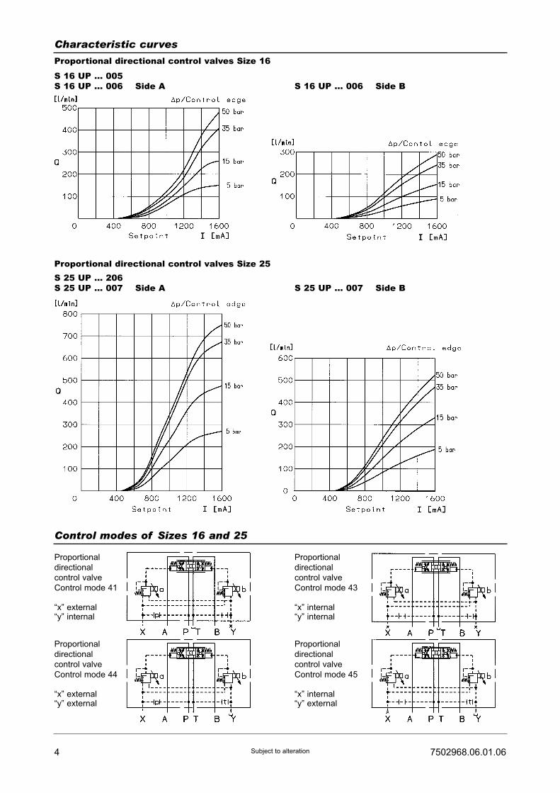
4 7502968.06.01.06Subject to alteration
Characteristic curves
Proportional directional control valves Size 16
S 16 UP ... 005S 16 UP ... 006 Side A S 16 UP ... 006 Side B
Proportional directional control valves Size 25S 25 UP ... 206S 25 UP ... 007 Side A S 25 UP ... 007 Side B
Control modes of Sizes 16 and 25
Proportional
directional
control valve
Control mode 41
“x” external“y” internal
Proportional
directional
control valve
Control mode 44
“x” external“y” external
Proportional
directional
control valve
Control mode 43
“x” internal“y” internal
Proportional
directional
control valve
Control mode 45
“x” internal“y” external

57502968.06.01.06 Subject to alteration
Equipment survey for proportional directional control valves Size 16(Standard design in control mode 43)Cat. No. for valves with different control mode on request
Symbol Neutral
position
Control
mode
Line
connection
Type Cat. No.
187
212
233
S 16 UP 43 10 G 187 005 3 O OS 16 UP 43 10 G 187 006 3 O O
43 Sub-plates
S 16 UP 43 10 G 212 005 3 O OS 16 UP 43 10 G 212 006 3 O O
S 16 UP 43 10 G 233 005 3 O OS 16 UP 43 10 G 233 006 3 O O
Re
turn
Ad
v.o
pe
nin
g
Inle
tA
dv.
op
en
ing
Le
aka
ge
oil
retu
rn
5204677.72985204678.7298
5204679.72985204680.7298
5204681.72985204682.7298
Equipment survey for proportional directional control valves Size 25(Standard design in control mode 43)Cat. No. for valves with different control mode on request
Symbol
Port size Type Cat. No.
Neutral
position
Control
mode
Line
connection
Type Cat. No.
187
212
233
S 25 UP 43 10 G 187 206 3 O OS 25 UP 43 10 G 187 007 3 O O
43 Sub-plates
S 25 UP 43 10 G 212 206 3 O OS 25 UP 43 10 G 212 007 3 O O
S 25 UP 43 10 G 233 206 3 O OS 25 UP 43 10 G 233 007 3 O O
Retu
rnA
dv.
openin
g
Inle
tA
dv.
openin
g
Leakage
oil
retu
rn
5204684.72985204685.7298
5204686.72985204687.7298
5204688.72985204689.7298
Subplates
G 3/4
G 1
G 1
G 1 1/4
G 1 1/2
16
16
25
25
25
P S 16 G 5 001 2 O O
P S 16 G 6 001 2 O O
P S 25 G 6 001 2 O O
P S 25 G 7 001 2 O O
P S 25 G 8 001 2 O O
10651861065187106518810651891065190
Nom.
size
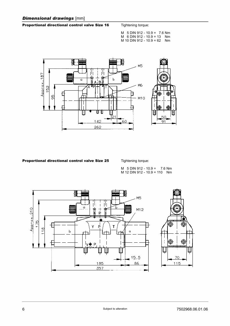
6 7502968.06.01.06Subject to alteration
Dimensional drawings [mm]
Proportional directional control valve Size 16 Tightening torque:
M 15 DIN 912 - 10.9 = 17.6 NmM 16 DIN 912 - 10.9 = 13.6 NmM 10 DIN 912 - 10.9 = 62.6 Nm
Proportional directional control valve Size 25 Tightening torque:
M 15 DIN 912 - 10.9 = 117.6 NmM 12 DIN 912 - 10.9 = 110.6 Nm

77502968.06.01.06 Subject to alteration
Dimensional drawings [mm]
Subplates Size 16 with interface to DIN 24 340-A 16 and ISO 4401-AD-07-4-ACat. No. 1065186 G 3/4Cat. No. 1065187 G 1
Cat. No. a
Dimensional table [mm]
G 3/4
G 1
b
Dia. 41
Dia. 47
c
16.5
18.5
10651861065187

8 7502968.06.01.06Subject to alteration
Dimensional drawings [mm]
Subplates Size 25 with interface to DIN 24 340-A 25 and ISO 4401-AE-08-4-ACat. No. 1065188 G 1Cat. No. 1065189 G 1 1/4
Cat. No. b1
Dimensional table [mm]
114
121
b2
26
30
d1
G 1
G 1 1/4
d2
Dia. 47
Dia. 56
h1
19
21
l1
26
30
10651881065189

97502968.06.01.06 Subject to alteration
Dimensional drawings [mm]
Subplates Size 25 with interface to DIN 24 340-A 25 and ISO 4401-AE-08-4-ACat. No. 1065190 G 1 1/2

10 7502968.06.01.06Subject to alteration
Sparea parts drawings
Size 16
Size 25
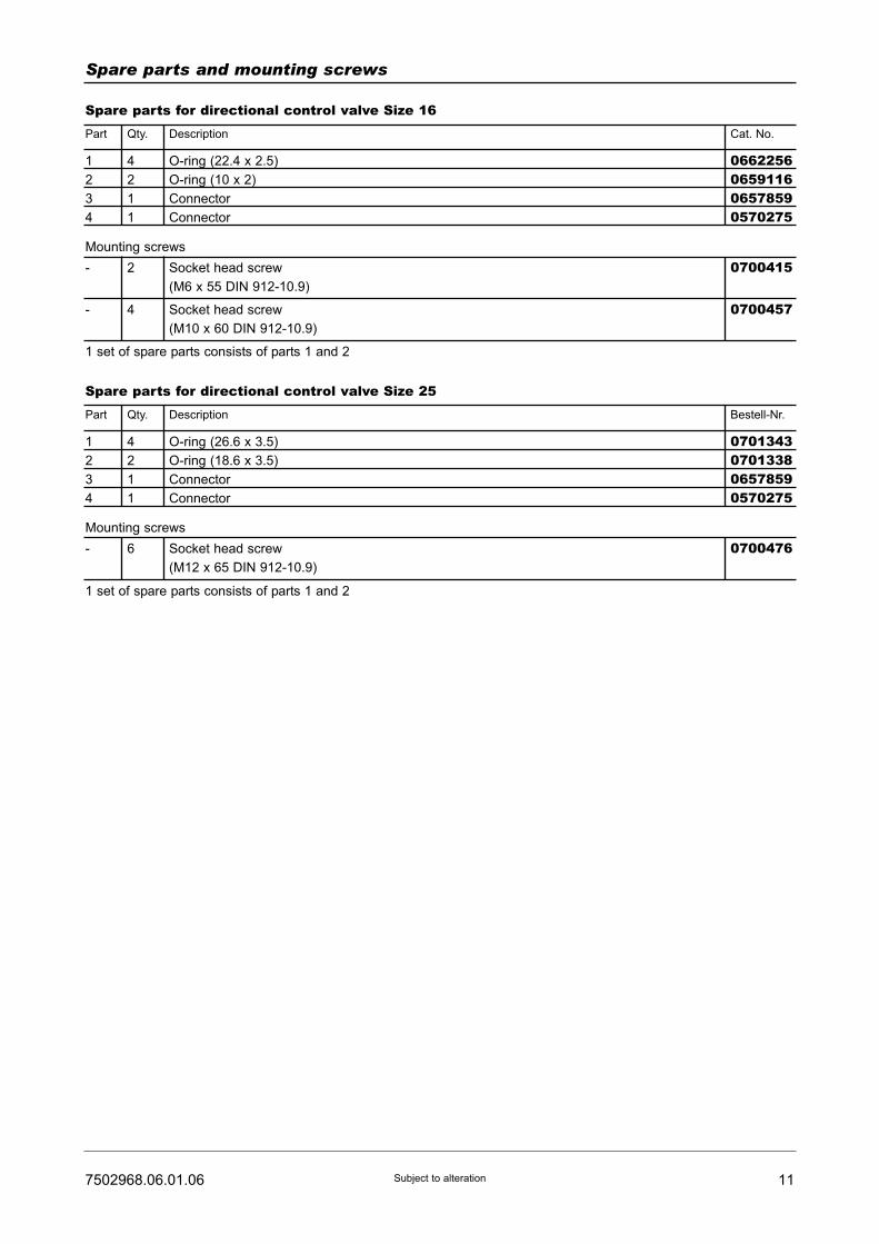
117502968.06.01.06 Subject to alteration
Spare parts and mounting screws
Spare parts for directional control valve Size 16Part Qty.
1
2
3
4
- 2 Socket head screw
(M6 x 55 DIN 912-10.9)
Mounting screws
4
2
1
1
O-ring (22.4 x 2.5)
O-ring (10 x 2)
Connector
Connector
0662256065911606578590570275
0700415
- 4 Socket head screw
(M10 x 60 DIN 912-10.9)
0700457
1 set of spare parts consists of parts 1 and 2
Description Cat. No.
Spare parts for directional control valve Size 25Part Qty.
1
2
3
4
- 6 Socket head screw
(M12 x 65 DIN 912-10.9)
Mounting screws
4
2
1
1
O-ring (26.6 x 3.5)
O-ring (18.6 x 3.5)
Connector
Connector
0701343070133806578590570275
0700476
1 set of spare parts consists of parts 1 and 2
Description Bestell-Nr.
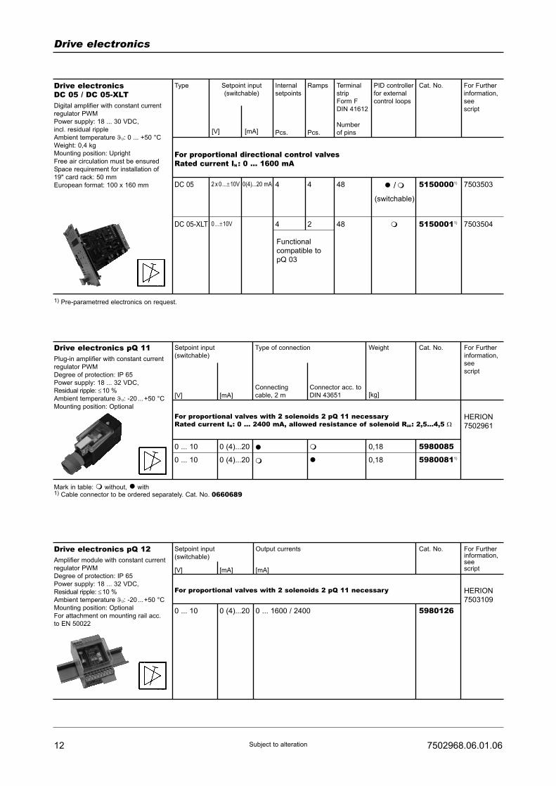
12 7502968.06.01.06Subject to alteration
Drive electronics
Drive electronicsDC 05 / DC 05-XLTDigital amplifier with constant current
regulator PWM
Power supply: 18 ... 30 VDC,
incl. residual ripple
Ambient temperature ϑU: 0 ... +50 °C
Weight: 0,4 kg
Mounting position: Upright
Free air circulation must be ensured
Space requirement for installation of
19" card rack: 50 mm
European format: 100 x 160 mm
Type
For proportional directional control valvesRated current IN : 0 ... 1600 mA
7503503
7503504
Setpoint input
(switchable)
Internal
setpoints
Pcs.
Ramps
Pcs.
Terminal
strip
Form F
DIN 41612
Number
of pins
PID controller
for external
control loops
Cat. No. For Further
information,
see
script
44
4 2
48
48
51500001)
51500011)
� /�
(switchable)
�
DC 05 2 x 0...±10V
0...±10V
0(4)...20 mA
DC 05-XLT
[V] [mA]
Functional
compatible to
pQ 03
Drive electronics pQ 11Plug-in amplifier with constant current
regulator PWM
Degree of protection: IP 65
Power supply: 18 ... 32 VDC,
Residual ripple: ≤10 %
Ambient temperature ϑU: -20 ...+50 °C
Mounting position: Optional
Setpoint input
(switchable)
For proportional valves with 2 solenoids 2 pQ 11 necessaryRated current IN: 0 ... 2400 mA, allowed resistance of solenoid R20: 2,5...4,5 Ω
HERION
7502961
[mA][V]
Type of connection
Connecting
cable, 2 m
Connector acc. to
DIN 43651
Weight
[kg]
Cat. No. For Further
information,
see
script
0 ... 10
0 ... 10
0 (4)...20
0 (4)...20
�
�
�
�
5980085
59800811)
0,18
0,18
Mark in table: � without, � with1) Cable connector to be ordered separately. Cat. No. 0660689
1) Pre-parametrred electronics on request.
Drive electronics pQ 12Amplifier module with constant current
regulator PWM
Degree of protection: IP 65
Power supply: 18 ... 32 VDC,
Residual ripple: ≤10 %
Ambient temperature ϑU: -20 ...+50 °C
Mounting position: Optional
For attachment on mounting rail acc.
to EN 50022
Setpoint input
(switchable)
For proportional valves with 2 solenoids 2 pQ 11 necessary HERION
7503109
[mA] [mA][V]
Output currents Cat. No. For Furtherinformation,seescript
0 ... 10 0 (4)...20 0 ... 1600 / 2400 5980126
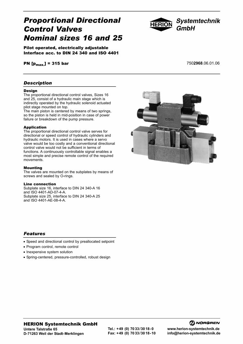
Proportional DirectionalControl ValvesNominal sizes 16 and 25Pilot operated, electrically adjustableInterface acc. to DIN 24 340 and ISO 4401
PN [pmax.] = 315 bar 7502968.06.01.06
DesignThe proportional directional control valves, Sizes 16and 25, consist of a hydraulic main stage which isindirectly operated by the hydraulic solenoid actuatedpilot stage mounted on top.The main piston is centered by means of two springs,so the piston is held in mid-position in case of powerfailure or breakdown of the pump pressure.
ApplicationThe proportional directional control valve serves fordirectional or speed control of hydraulic cylinders andhydraulic motors. It is used in cases where a servovalve would be too costly and a conventional directionalcontrol valve would not be sufficient in terms offunctions. A continuously controllable signal enables amost simple and precise remote control of the requiredmovements.
MountingThe valves are mounted on the subplates by means ofscrews and sealed by O-rings.
Line connectionSubplate size 16, interface to DIN 24 340-A 16and ISO 4401-AD-07-4-A.Subplate size 25, interface to DIN 24 340-A 25and ISO 4401-AE-08-4-A.
• Speed and directional control by preallocated setpoint
• Program control, remote control
• Inexpensive system solution
• Spring-centered, pressure-controlled, robust design
Description
Features
HERION Systemtechnik GmbHUntere Talstraße 65
D-71263 Weil der Stadt-Merklingen
Tel.: +49 (0) 70 33/30 18-0
Fax: +49 (0) 70 33/30 18-10
www.herion-systemtechnik.de
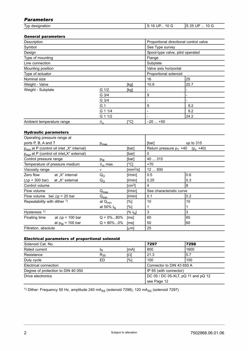
Typ designation S 16 UP... 10 G S 25 UP ... 10 G
General parametersDescription Proportional directional control valve
Symbol See Type survey
Design Spool-type valve, pilot operated
Type of mounting Flange
Line connection Subplate
Mounting position Valve axis horizontal
Type of actuator Proportional solenoid
Nominal size 16 25
Weight - Valve [kg] 10.9 20.7
Weight - Subplate G 1/2 [kg] - -
G 3/4 9 -
G 3/4 - -
G 1 9 29.2
G 1 1/4 - 29.2
G 1 1/2 - 24.2
Ambient temperature range ϑu [°C] –20 ... +50
Hydraulic parametersOperating pressure range at
ports P, B, A and T pmax [bar] up to 315
pmin at P (control oil inlet „X“ internal) [bar] Return pressure pT +40 (py +40)
pmin at P (control oil inlet„X“ external) [bar] 0
Control pressure range pSt [bar] 40 ... 315
Temperature of pressure medium ϑm max. [°C] +70
Viscosity range ν [mm2/s] 12 ... 500
Zero flow at „X“ internal QO [l/min] 0.5 0.6
(Vp = 300 bar) at „X“ external QO [l/min] 0.25 0.3
Control volume [cm3] 4 8
Flow volume Qmax [l/min] See characteristic curve
Flow volume bei Vp = 20 bar Qmin [l/min] 0.1 0.2
Repeatability with dither 1) at Qmin [%] 10 10
at 50% IN [%] 1 1
Hysteresis 1) [% IN] 3 3
Floating time at Vp = 100 bar Q = 0%...80% [ms] 60 65
at pSt = 100 bar Q = 80%...0% [ms] 50 60
Filtration, absolute [μm] 25
Electrical parameters of proportional solenoidSolenoid Cat. No. 7297 7298Rated current IN [mA] 800 1600
Resistance R20 [Ω] 21.3 5.7
Duty cycle ED [%] 100 100
Electrical connection Connector to DIN 43 650 A
Degree of protection to DIN 40 050 IP 65 (with connector)
Drive electronics DC 05 / DC 05-XLT, pQ 11 and pQ 12
see Page 12
1) Dither: Frequency 50 Hz, amplitude 240 mASS (solenoid 7298), 120 mASS (solenoid 7297)
2 7502968.06.01.06Subject to alteration
Parameters
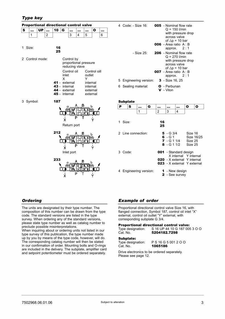
37502968.06.01.06 Subject to alteration
Type key
SubplateP S ... G ... ... ... O O
1 2 3 4
1 Size: 1625
2 Control mode: Control by proportional pressure reducing vlave
Control oil Control oillinlet outletX Y
41 - external internal43 - internal internal44 - external external45 - internal external
3 Symbol: 187
Return port
212
Inlet port
233
1 Size: 1625
2 Line connection: 5 - G 3/4 Size 166 - G 1 Size 16/257 - G 1 1/4 Size 258 - G 1 1/2 Size 25
3 Code: 001 - Standard designX internal Y internal
020 - X external Y internal023 - X external Y external
4 Engineering version: 1 - New design2 - See survey
S ... UP ... 10 G ... ... ... O ...1 2 3 4 5 6
Proportional directional control valve 4 Code: - Size 16: 005 - Nominal flow rateQ = 150 l/minwith pressure dropacross valveof Vp = 10 bar
006 - Area ratio A : Bapprox. 2 : 1
Code: - Size 25: 206 - Nominal flow rateQ = 270 l/minwith pressure dropacross valveof Vp = 10 bar
007 - Area ratio A : Bapprox. 2 : 1
5 Engineering version: 3 - Size 16, 25
6 Sealing material: O - PerbunanV - Viton
Ordering Example of order
The units are designated by their type number. Thecomposition of this number can be drawn from the typecode. The standard versions are listed in the typesurvey. When ordering any of the standard versions,please state type number as well as catalog number topreclude possible misinterpretations.When inquiring about or ordering units not listed in ourtype survey of this publication, the type number madeup by you by means of the type code, however, will do.The corresponding catalog number will then be statedin our confirmation of order. Mounting bolts and O-ringsare included in the delivery. The subplate, amplifier cardand setpoint potentiometer must be ordered separately.
Proportional directional control valve Size 16, withflanged connection, Symbol 187, control oil inlet “X”external, control oil outlet “Y” external, withcorresponding subplate G 3/4.
Proportional directional control valve:Type designation: S 16 UP 44 10 G 187 005 3 O OCat. No. 5204182.7298Subplate:Type designation: P S 16 G 5 001 2 O OCat. No. 1065186Drive electronics to be ordered separately.Please see page 12.

4 7502968.06.01.06Subject to alteration
Characteristic curves
Proportional directional control valves Size 16
S 16 UP ... 005S 16 UP ... 006 Side A S 16 UP ... 006 Side B
Proportional directional control valves Size 25S 25 UP ... 206S 25 UP ... 007 Side A S 25 UP ... 007 Side B
Control modes of Sizes 16 and 25
Proportional
directional
control valve
Control mode 41
“x” external“y” internal
Proportional
directional
control valve
Control mode 44
“x” external“y” external
Proportional
directional
control valve
Control mode 43
“x” internal“y” internal
Proportional
directional
control valve
Control mode 45
“x” internal“y” external
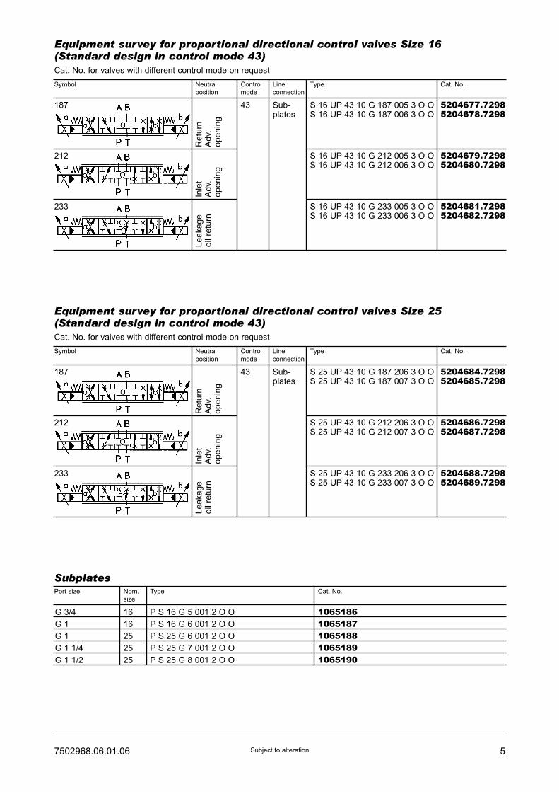
57502968.06.01.06 Subject to alteration
Equipment survey for proportional directional control valves Size 16(Standard design in control mode 43)Cat. No. for valves with different control mode on request
Symbol Neutral
position
Control
mode
Line
connection
Type Cat. No.
187
212
233
S 16 UP 43 10 G 187 005 3 O OS 16 UP 43 10 G 187 006 3 O O
43 Sub-plates
S 16 UP 43 10 G 212 005 3 O OS 16 UP 43 10 G 212 006 3 O O
S 16 UP 43 10 G 233 005 3 O OS 16 UP 43 10 G 233 006 3 O O
Re
turn
Ad
v.o
pe
nin
g
Inle
tA
dv.
op
en
ing
Le
aka
ge
oil
retu
rn
5204677.72985204678.7298
5204679.72985204680.7298
5204681.72985204682.7298
Equipment survey for proportional directional control valves Size 25(Standard design in control mode 43)Cat. No. for valves with different control mode on request
Symbol
Port size Type Cat. No.
Neutral
position
Control
mode
Line
connection
Type Cat. No.
187
212
233
S 25 UP 43 10 G 187 206 3 O OS 25 UP 43 10 G 187 007 3 O O
43 Sub-plates
S 25 UP 43 10 G 212 206 3 O OS 25 UP 43 10 G 212 007 3 O O
S 25 UP 43 10 G 233 206 3 O OS 25 UP 43 10 G 233 007 3 O O
Retu
rnA
dv.
openin
g
Inle
tA
dv.
openin
g
Leakage
oil
retu
rn
5204684.72985204685.7298
5204686.72985204687.7298
5204688.72985204689.7298
Subplates
G 3/4
G 1
G 1
G 1 1/4
G 1 1/2
16
16
25
25
25
P S 16 G 5 001 2 O O
P S 16 G 6 001 2 O O
P S 25 G 6 001 2 O O
P S 25 G 7 001 2 O O
P S 25 G 8 001 2 O O
10651861065187106518810651891065190
Nom.
size

6 7502968.06.01.06Subject to alteration
Dimensional drawings [mm]
Proportional directional control valve Size 16 Tightening torque:
M 15 DIN 912 - 10.9 = 17.6 NmM 16 DIN 912 - 10.9 = 13.6 NmM 10 DIN 912 - 10.9 = 62.6 Nm
Proportional directional control valve Size 25 Tightening torque:
M 15 DIN 912 - 10.9 = 117.6 NmM 12 DIN 912 - 10.9 = 110.6 Nm
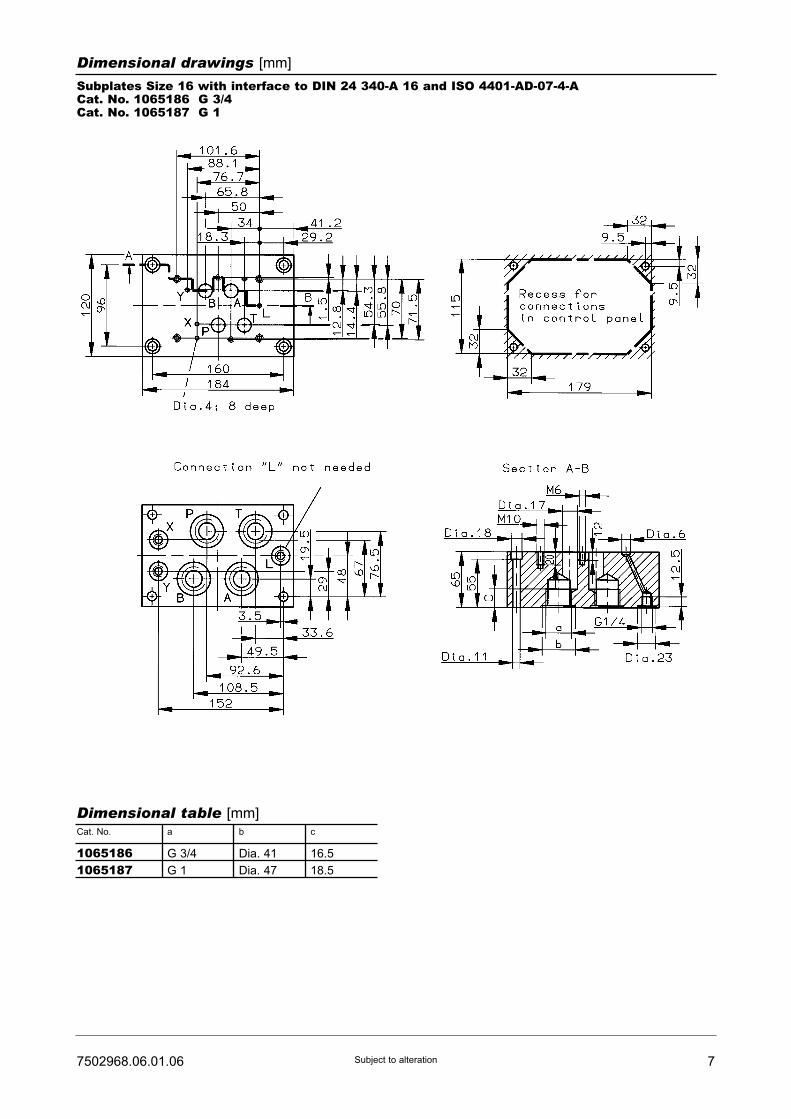
77502968.06.01.06 Subject to alteration
Dimensional drawings [mm]
Subplates Size 16 with interface to DIN 24 340-A 16 and ISO 4401-AD-07-4-ACat. No. 1065186 G 3/4Cat. No. 1065187 G 1
Cat. No. a
Dimensional table [mm]
G 3/4
G 1
b
Dia. 41
Dia. 47
c
16.5
18.5
10651861065187
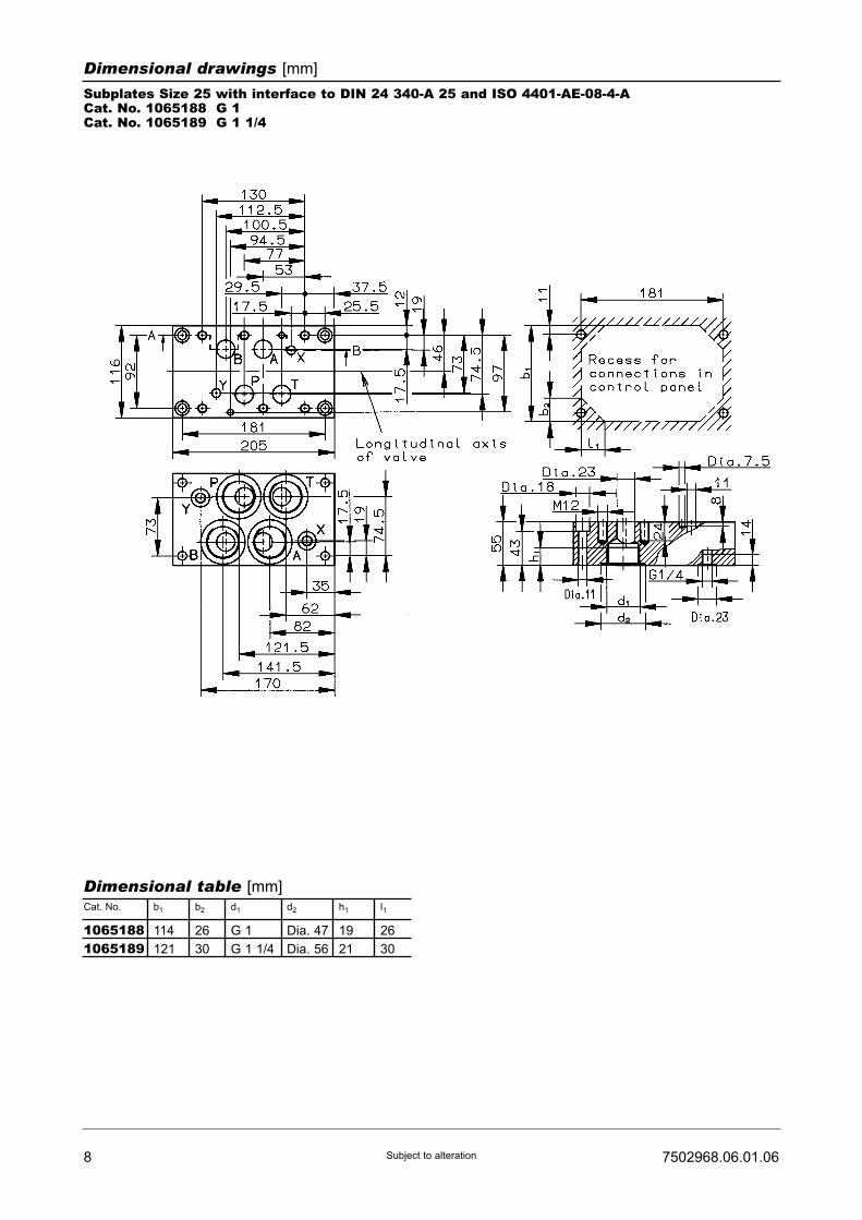
8 7502968.06.01.06Subject to alteration
Dimensional drawings [mm]
Subplates Size 25 with interface to DIN 24 340-A 25 and ISO 4401-AE-08-4-ACat. No. 1065188 G 1Cat. No. 1065189 G 1 1/4
Cat. No. b1
Dimensional table [mm]
114
121
b2
26
30
d1
G 1
G 1 1/4
d2
Dia. 47
Dia. 56
h1
19
21
l1
26
30
10651881065189
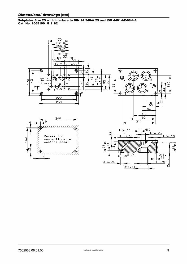
97502968.06.01.06 Subject to alteration
Dimensional drawings [mm]
Subplates Size 25 with interface to DIN 24 340-A 25 and ISO 4401-AE-08-4-ACat. No. 1065190 G 1 1/2

10 7502968.06.01.06Subject to alteration
Sparea parts drawings
Size 16
Size 25

117502968.06.01.06 Subject to alteration
Spare parts and mounting screws
Spare parts for directional control valve Size 16Part Qty.
1
2
3
4
- 2 Socket head screw
(M6 x 55 DIN 912-10.9)
Mounting screws
4
2
1
1
O-ring (22.4 x 2.5)
O-ring (10 x 2)
Connector
Connector
0662256065911606578590570275
0700415
- 4 Socket head screw
(M10 x 60 DIN 912-10.9)
0700457
1 set of spare parts consists of parts 1 and 2
Description Cat. No.
Spare parts for directional control valve Size 25Part Qty.
1
2
3
4
- 6 Socket head screw
(M12 x 65 DIN 912-10.9)
Mounting screws
4
2
1
1
O-ring (26.6 x 3.5)
O-ring (18.6 x 3.5)
Connector
Connector
0701343070133806578590570275
0700476
1 set of spare parts consists of parts 1 and 2
Description Bestell-Nr.

12 7502968.06.01.06Subject to alteration
Drive electronics
Drive electronicsDC 05 / DC 05-XLTDigital amplifier with constant current
regulator PWM
Power supply: 18 ... 30 VDC,
incl. residual ripple
Ambient temperature ϑU: 0 ... +50 °C
Weight: 0,4 kg
Mounting position: Upright
Free air circulation must be ensured
Space requirement for installation of
19" card rack: 50 mm
European format: 100 x 160 mm
Type
For proportional directional control valvesRated current IN : 0 ... 1600 mA
7503503
7503504
Setpoint input
(switchable)
Internal
setpoints
Pcs.
Ramps
Pcs.
Terminal
strip
Form F
DIN 41612
Number
of pins
PID controller
for external
control loops
Cat. No. For Further
information,
see
script
44
4 2
48
48
51500001)
51500011)
� /�
(switchable)
�
DC 05 2 x 0...±10V
0...±10V
0(4)...20 mA
DC 05-XLT
[V] [mA]
Functional
compatible to
pQ 03
Drive electronics pQ 11Plug-in amplifier with constant current
regulator PWM
Degree of protection: IP 65
Power supply: 18 ... 32 VDC,
Residual ripple: ≤10 %
Ambient temperature ϑU: -20 ...+50 °C
Mounting position: Optional
Setpoint input
(switchable)
For proportional valves with 2 solenoids 2 pQ 11 necessaryRated current IN: 0 ... 2400 mA, allowed resistance of solenoid R20: 2,5...4,5 Ω
HERION
7502961
[mA][V]
Type of connection
Connecting
cable, 2 m
Connector acc. to
DIN 43651
Weight
[kg]
Cat. No. For Further
information,
see
script
0 ... 10
0 ... 10
0 (4)...20
0 (4)...20
�
�
�
�
5980085
59800811)
0,18
0,18
Mark in table: � without, � with1) Cable connector to be ordered separately. Cat. No. 0660689
1) Pre-parametrred electronics on request.
Drive electronics pQ 12Amplifier module with constant current
regulator PWM
Degree of protection: IP 65
Power supply: 18 ... 32 VDC,
Residual ripple: ≤10 %
Ambient temperature ϑU: -20 ...+50 °C
Mounting position: Optional
For attachment on mounting rail acc.
to EN 50022
Setpoint input
(switchable)
For proportional valves with 2 solenoids 2 pQ 11 necessary HERION
7503109
[mA] [mA][V]
Output currents Cat. No. For Furtherinformation,seescript
0 ... 10 0 (4)...20 0 ... 1600 / 2400 5980126
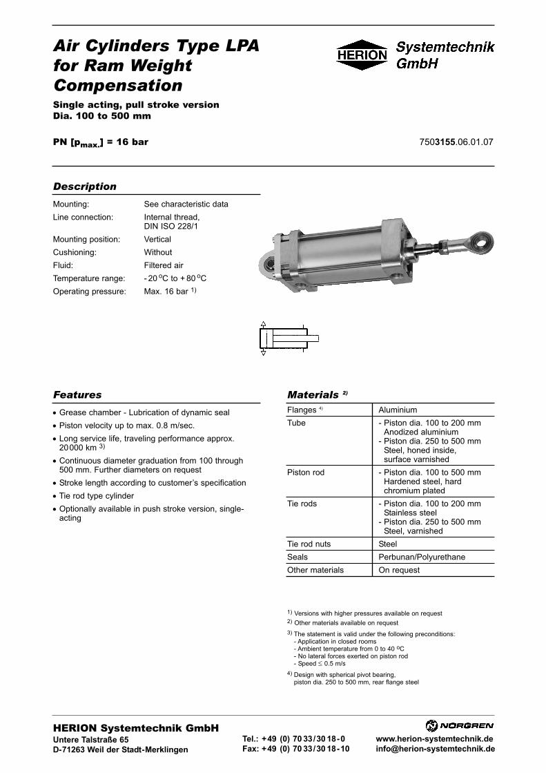
Air Cylinders Type LPAfor Ram WeightCompensationSingle acting, pull stroke versionDia. 100 to 500 mm
PN [pmax.] = 16 bar 1) 7503155.06.01.07
HERION Systemtechnik GmbHUntere Talstraße 65
D-71263 Weil der Stadt-Merklingen
Tel.: +49 (0) 70 33/30 18-0
Fax: +49 (0) 70 33/30 18-10
www.herion-systemtechnik.de
Features Materials 2)
Flanges 4) Aluminium
Tube - Piston dia. 100 to 200 mmAnodized aluminium
- Piston dia. 250 to 500 mmSteel, honed inside,surface varnished
Piston rod - Piston dia. 100 to 500 mmHardened steel, hardchromium plated
Tie rods - Piston dia. 100 to 200 mmStainless steel
- Piston dia. 250 to 500 mmSteel, varnished
Tie rod nuts Steel
Seals Perbunan/Polyurethane
Other materials On request
• Grease chamber - Lubrication of dynamic seal
• Piston velocity up to max. 0.8 m/sec.
• Long service life, traveling performance approx.20000 km 3)
• Continuous diameter graduation from 100 through500 mm. Further diameters on request
• Stroke length according to customer’s specification
• Tie rod type cylinder
• Optionally available in push stroke version, single-acting
Mounting: See characteristic data
Line connection: Internal thread,DIN ISO 228/1
Mounting position: Vertical
Cushioning: Without
Fluid: Filtered air
Temperature range: - 20 oC to + 80 oC
Operating pressure: Max. 16 bar 1)
Description
1) Versions with higher pressures available on request
2) Other materials available on request
3) The statement is valid under the following preconditions:- Application in closed rooms- Ambient temperature from 0 to 40 oC- No lateral forces exerted on piston rod- Speed ≤ 0.5 m/s
4) Design with spherical pivot bearing,piston dia. 250 to 500 mm, rear flange steel
2 7503155.06.01.07Subject to alteration
Stroke tolerances [mm]
Characteristic data
Example of order: LPA cylinder, 500 mm (dia.) x 150 mm (stroke), basic design.
Basic number Basic design Stroke length
Order No.: 43 170 18 150
Different versionsBasic No.
100
125
160
200
250
320
400
500
25
30
32
40
40
50
63
80
2 x G 3/4
2 x G 3/4
2 x G 1
2 x G 1 1/4
2 x G 1 1/4
2 x G 1 1/2
2 x G 1 1/2
2 x G 2
43 170
43 170
43 170
43 170
43 170
43 170
43 170
43 170
73.63
115.65
193.02
301.59
478.30
784.61
1225.46
1913.23
10
11
12
13
14
15
16
18
34
35
36
37
-
-
-
-
30
31
32
33
-
-
-
-
20
21
22
23
24
25
26
28
Piston dia[mm]
Piston roddia.[mm]
Lineconnectionin headend
Annulararea ofpiston[cm2]
Basicdesign
Cap endflange
Head endflange
Sphericalpivotbearing
Piston dia. Stroke ≤ 500 Stroke > 500 to 1250
100
125 -320
400 -500
100
125 -250
320 -500
±1.6
±2
±2.5
+2.50
+40
+60
+40
+50
+70
Over-all tolerances [mm]
Piston dia. Dimensions like ZB, ZF, ZJ, XN (see Page 3)

37503155.06.01.07 Subject to alteration
Dimensional drawings and tables [in mm]
Piston dia. 100 to 200
Basic design
BG
17
17
23
27
E
116
140
180
220
EE
G 3/4
G 3/4
G 1
G 1 1/4
EP
18
22
25
25
EX LT MF Dia.MM MS PL
25
31
37
37
Dia.FB
14
16
18
22
KK
M20x1.5
M24x2
M27x2
M27x2
16
16
20
20
25
30
32
40
28
35
42
42
20
20
24
30
R
75
90
115
135
Dia.CX
20
25
30
30
100
125
160
200
Tolerance
Piston dia.
d11 H8 -1 -0.1 H13 6g ±0.2 h9 JS14±0.5
34
39
53
53
Dia.AA
120
150
190
232
AM
40
48
54
54
Dia.B
55
60
80
80
UF
180
222
278
318
VD
20
20
25
25
W
20
20
25
25
WH
36
36
45
45
XN ZF Dia. d4 Dia. d9 l11 l12
199
210
249
284
Z [o]
10
10
10
10
ZB
160
165
194
225
107
132
170
210
33
33
40
50
170
176
209
240
40
40
48
60
l13
120
140
180
235
VA
4
5
5
5
100
125
160
200
Tolerance
Piston dia.
JS14 * max. * * +0.46H
40
40
48
60
RT
M10
M10
M12
M14
SW
22
24
30
32
TF
150
180
230
270
Mounting flange for cap end/head end Pivot bearing, spherical
* For tolerances, see Page 2
ZB + Stroke
ZF + Stroke XN + Stroke
View “A”

4 7503155.06.01.07Subject to alteration
Dimensional drawings and tables [in mm]
Piston dia. 250 to 500
Basic design
BG
24
24
30
42
Dia. D EE
320
395
485
620
G 1 1/4
G 1 1/2
G 1 1/2
G 2
EP KK Dia. MMLT
30
40
50
65
40
50
63
80
EX
85
100
115
150
M33 x 2
M42 x 2
M48 x 2
M64 x 3
MS
50
60
70
90
Dia. CX
40
50
63
80
250
320
400
500
Tolerance
Piston dia.
H8 -1 6g±0.3 f7±0.5
40
50
63
80
Dia. AA
285
360
445
560
AM
65
70
80
100
SW
32
41
50
65
XN ZJ
320
370
400
500
232
270
285
350
Z [o] l2 l12l11
4
4
4
4
262
336
419
521
Dia. d4
65
75
75
85
15
15
18
25
WH
25
30
35
40
250
320
400
500
Tolerance
Piston dia.
* * max.6H
52
60
60
75
PL
34
37.5
37.5
42.5
RT
M16
M16
M20
M30
Pivot bearing, spherical
* For tolerances, see Page 2
ZJ + Stroke
View “A”
XN + StrokeView “A”

57503155.06.01.07 Subject to alteration
Sectional drawings
Piston dia. 100 to 200
Piston dia. 250 to 500
1 Cylinder tube2 Head end3 Cap end4 Piston rod
19 Tie rod12 Nut16 Nut17 Bush
* 18 Piston* 20 Seal* 21 O-ring* 22 Seal
34 Disc35 Disc
* 38 Grease
1 Cylinder tube2 Head end3 Cap end4 Piston rod5 Bush6 Piston
17 Disc18 Screw19 Screw10 Nut11 Tie rod12 Nut
* 21 O-ring* 22 O-ring* 23 Seal* 24 Seal* 25 Guide strip* 26 Grease 3)
* 28 Piston rod wiper(dia. 500 mm only)
All parts marked with an asterisk * are enclosed in the respective spare parts kit.When ordering other parts, please state all data contained in type plate (Order No., date of delivery, etc.)
Spare parts kits1)
Piston dia.(mm)
Kit Order No. Tightening torque,lubricated, Item 12 2)
100
125
160
200
1114300111430111143021114303
20 Nm
28 Nm
50 Nm
80 Nm
Piston dia.(mm)
Kit Order No. Tightening torque,lubricated, Item 12 2)
250
320
400
500
1114304111430511143061114308
175 Nm
175 Nm
150 Nm
350 Nm
1) After replacement of wearing parts, the grease chambers of the headend and the piston must be refilled with grease in addition to theroutine lubrication of the sealing surfaces. The grease required isenclosed in the respective spare parts kit.
2) With long strokes, identical distances between cylinder tube and tierods must be ensured. Alternately tighten, a little at a time, two tie rodnuts across from each other. Then tighten to full torque given in table.
3) The grease (Centoplex GLP 500, manufactured by Klüber) for greasechamber of cylinder piston/dia. 250 to 500 mm, is furnishedseparately. Prior to commissioning, fill up required quantity at ltem 9.The grease chamber is to be checked every 3 months (Item 9).
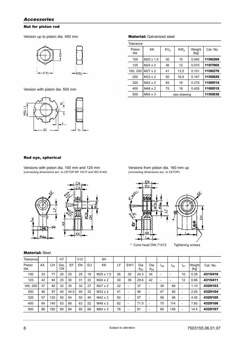
6 7503155.06.01.07Subject to alteration
Accessories
Nut for piston rod
Version up to piston dia. 450 mm
Rod eye, spherical
Versions with piston dia. 100 mm and 125 mm(connecting dimensions acc. to CETOP RP 103 P and ISO 8140)
Versions from piston dia. 160 mm up(connecting dimensions acc. to CETOP)
Version with piston dia. 500 mm
KW2
10
12
13,5
16,5
16
18
Cat. No.
1106269
1107965
1106270
1150829
1100514
1100515
1150830
Weight[kg]
0.040
0.070
0.101
0.167
0.278
0.426
100
125
160, 200
250
320
400
500
Tolerance
KKPistondia.
M20 x 1,5
M24 x 2
M27 x 2
M33 x 2
M42 x 2
M48 x 2
M64 x 3 see drawing
KV2
30
36
41
50
65
75
EF
25
30
35
44.5
54
66
84
EU
18
22
27
32
40
52
66
KK
M20 x 1,5
M24 x 2
M27 x 2
M33 x 2
M42 x 2
M48 x 2
M64 x 3
LF
26
30
32
41
50
62
78
SW1 l39 l40 l41 Weight[kg]
30
36
-
-
-
-
-
Diad23
24.3
29.6
37
46
57
71.5
91
Diad24
34
42
-
-
-
-
-
-
-
66
80
96
114
148
10
12
-
-
-
-
-
-
-
38
47
58
70
90
EN
25
31
32
40
50
63
80
100
125
160, 200
250
320
400
500
Tolerance
Pistondia.
H7 h12 6H
AX
33
42
37
46
57
64
86
CH
77
94
80
97
120
140
180
Dia.CN
20
25
32
40
50
63
80
Material: Steel
Cat. No.
4315410
4315411
4329103
4329104
4329105
4329106
4329107
0.39
0.66
1.10
2.05
4.45
7.60
14.5
Material: Galvanized steel
Cone head DIN 71412 Tightening screws