Embed Size (px)
Citation preview

HelperTech.
School of Engineering Science, Burnaby, BC, V5A 1S6
February 14, 2010
Dr. Andrew Rawicz
School of Engineering Science
Simon Fraser University
8888 University Drive
Burnaby, BC
V5A 1S6
Re: ENSC 305/440 Design Specification for Remote Control Snow Blower Robot
Dear Dr. Rawicz:
The enclosed document clearly describes the design specification of our developing snow
blower robot, RoboBlow, which is a wireless remote control robot for snow removal. Our
proposed robot will provide the utility of snow removal without the necessity of going
outdoors in person. The main functionality of the robot will include salt spraying, snow
throwing, and real time video transmission from the robot to the remote controller.
The attached document describes the design specification to achieve the functionality
requirements of the robot as well as the solutions and the systems in mechanical, electrical,
and programming aspects. The mechanical parts and models that will be used in this project
are also listed in this attachment.
HelperTech is a research team found by four talented and innovative senior engineering
students: Leo Cheng, Peter Hsiao, Joseph Shen, and YuYuan Liu. If there are any questions
or concerns regarding our proposal, please feel free to contact me by phone or by email.
Sincerely,
Leo Cheng
President and CEO, HelperTech
Phone: (604) 760-1283
Email: [email protected]
Enclosure: Design Specification for Remote Control Snow Blower Robot

Design Specification
Remote Control Snow Blower Robot Spring 2011
Submitted to: Andrew Rawicz (ENSC 440)
Michael Sjoerdsma (ENSC 305)
Project Team: Leo Cheng (301084573)
Peter Hsiao (301025638)
YuYuan Liu (301046236)
Joseph Shen (301032167)

Design Specification for Remote Control Snow Blower Robot
ii
Executive Summary
This design specification document provides detail description of the technical solutions to
the functional requirements of RoboBlow, which is a remote-controlled robot for snow
removal. RoboBlow can be controlled wirelessly and it is attached with two cameras, one
snow thrower, and one mechanical part to spray salt for snow removal such that the user can
stay indoors and remove snow outdoors.
Section 2 discusses the design of snow thrower in the physical, mechanical, and electrical
aspects. Section 3 describes the solution to snow-out direction control with the physical
design and method to monitor the snow-out process. Section 4 discusses the salt spraying unit
and section 5 shows the overall physical design of the robot. Finally, section 6 provides a
detail description on the remote controller in various aspects.
This document is believed to explain the design specifications to the RoboBlow functionality
and following the design specifications in this document should lead to a completion of the
prototype of RoboBlow.

Design Specification for Remote Control Snow Blower Robot
iii
Table of Contents
Executive Summary .......................................................................................................................... ii
List of Figures ................................................................................................................................... vi
Glossary ......................................................................................................................................... viii
1. Introduction .................................................................................................................................. 1
1.1 Scope ...................................................................................................................................... 1
1.2 Audience ................................................................................................................................. 1
2. Snow thrower Module .................................................................................................................. 2
2.1 Snow Thrower Physical and Mechanical Design .................................................................... 2
2.2 Snow Thrower Electrical Design and Power .......................................................................... 3
2.2.1 Circuit diagram: ............................................................................................................... 3
2.2.2 Part information: ............................................................................................................. 3
2.2.3 Operating Limits .............................................................................................................. 4
2.3 Power Distribution.................................................................................................................. 5
2.3.1 Electronic Design ............................................................................................................. 6
2.4 Driving Unit ............................................................................................................................. 8
2.4.1 Physical and Mechanical Design ...................................................................................... 8
2.4.2 Electronic Design ...........................................................................................................10
2.5 Safety Design ........................................................................................................................12
2.6 Test Plan ...............................................................................................................................14
3. Snow-out Direction Unit .............................................................................................................15
3.1 Physical and Mechanical Design ...........................................................................................15

Design Specification for Remote Control Snow Blower Robot
iv
3.1.1 Control Circuit ................................................................................................................16
3.1.2 Method of attaching ......................................................................................................17
3.2 Camera Unit ..........................................................................................................................17
3.2.1 Physical design ...............................................................................................................17
3.2.2 Camera...........................................................................................................................18
3.2.3 Step Motor Connection .................................................................................................18
4. Salt Spraying Unit .......................................................................................................................20
4.1 Physical and Mechanical Design ...........................................................................................20
4.2 The Salt Stopper ...................................................................................................................20
4.3 The Salt Filter ........................................................................................................................21
5. The Entire Body Building ............................................................................................................22
5.1 Physical Design .....................................................................................................................22
5.2 Method of Connection .........................................................................................................23
5.3 Partition in the Bottom Board ..............................................................................................23
6. Remote controller ......................................................................................................................24
6.1 physical design specification ................................................................................................24
6.1.1 Dimension, weight and material ...................................................................................25
6.1.2 Controller panel design .................................................................................................25
6.1.3 Internal structure...........................................................................................................26
6.2 Hardware design specification .............................................................................................26
6.3 Software design specification .............................................................................................27
6.3.1 Driver development .......................................................................................................27
6.3.2 Software architecture in Nutshell .................................................................................28
6.3.2 Algorithm flow chart ......................................................................................................28
6.4 Control module inside the robot ..........................................................................................29

Design Specification for Remote Control Snow Blower Robot
v
6.4.1 Hardware design ............................................................................................................29
6.4.2 Software design specification ........................................................................................29
7 Conclusion ...................................................................................................................................30
8 Appendix .......................................................................................................................................31
9 References ...................................................................................................................................44

Design Specification for Remote Control Snow Blower Robot
vi
List of Figures
Figure 1: Yardworks Electric Snow Thrower 2
Figure 2: Power switch module for the snow thrower 3
Figure 3: Inside the Power Distribution Module 5
Figure 4: ATX Power Supply Main Connector 6
Figure 5: Driving Unit Module 8
Figure 6: DC geared motor CAD diagram, units are in inches 8
Figure 7: H-Bridge Schematic 10
Figure 8: adding Heat Sink to the power transistor 11
Figure 9: Flashing LED using microcontroller 12
Figure 10: Motion Detection for Warning Alarm 13
Figure 11: Testing the power switch circuit with low power application 14
Figure 12: Snow Thrower and the Vane 15
Figure 13: Stepper Motor 15
Figure 14: PCB connection of the L293N IC and the motors 16
Figure 15: Camera location in the robot 17
Figure 16: PCB connection of the L293N IC and the motors 18
Figure 17: Electromagnet 20
Figure 18: Tea set filter 21
Figure 19: Physical design of the robot 22
Figure 20: Partition in the Bottom Board 23
Figure 21: the remote controller with cover opened. 24

Design Specification for Remote Control Snow Blower Robot
vii
Figure 22 the remote controller with the cover closed 24
Figure 23: the top-view of the remote controller 25
Figure 24 the software architecture in the controller 28
Figure 25: Software architecture in the robot 29

Design Specification for Remote Control Snow Blower Robot
viii
Glossary
LCD Liquid Crystal Display, a flat electronic visual display
Snow Intake The amount of snow that the snow thrower can handle at a given
moment
H-bridge A well know electronic circuit used to control motor rotation
direction
ARM9 The version 9 ARM CPU. ARM is a global leading company for
designing embedded system processor. ARM9 is one of their product
models.
MCU Micro-controller. It is a small computer on a single IC containing a
processor, memory and programmable I/O [2]. It is usually used in
automatically controlled products and devices.
IEEE 802.11 It is a set of standards carrying out wireless local area network
computer communication in the 2.4, 3.6 and 5 GHz [1].
USB HID The USB human interface device class ("USB HID class") is a USB
device class that describes human interface devices such as
keyboards, mice, game controllers and alphanumeric display devices.
Linux kernel The Linux kernel is an operating system kernel used by the Linux
family of Unix-like operating systems. It is one of the most
prominent examples of free and open source software.

Design Specification for Remote Control Snow Blower Robot
1
1. Introduction RoboBlow is a remote-controlled snow thrower robot which enables its operator to
remove the snow and prevent ice formation on walkways or driveways while staying
inside his/her home. The remote controller of RoboBlow allows its operator to move
RoboBlow in any direction with desirable speeds and offers the utility to switch on/off a
snow thrower attached to the robot and to spray salt from the robot. This design
specification discusses the technical approach to the RoboBlow development for these
functions and the functional specifications outlined in the document of RoboBlow
Functional Specification.
1.1 Scope
This design specification clearly describes the technical solutions for RoboBlow
development to approach the requirements listed in the RoboBlow Functional
Specification.
The possible hardware and software approaches are discussed in this document.
1.2 Audience
This document is proposed for development use in the HelperTech research team. This
document has provided a design guideline with the detail solutions to the final product
requirements. Engineers should use this document as reference when implementing and
testing the final product.

Design Specification for Remote Control Snow Blower Robot
2
2. Snow thrower Module
2.1 Snow Thrower Physical and Mechanical Design
Due to the level of difficulties and time limitations, we decide to purchase an off market
electrical powered snow thrower from Canadian Tire [1]. The figure below shows the
thrower unit we will facilitate.
Figure 1: Yardworks Electric Snow Thrower
The blade shown in the figure is rotated by an AC motor inside the snow thrower. The
purpose of the blade is to “stir” the snow in the front and creates an upward force to the
snow. The vane can be rotated manually so the snow with upward force can be blown into
a desired direction. (The direction of the vane will be robotized and is discussed in
another section.)The physical and mechanical specification and limits are lists on the
operation manual and are presented in the table below.
Table1: Snow Thrower Physical and Mechanical Specification Specification
Blade Speed Up to 2600 RPM (no load)
Clearing Width 40.6 cm
Clearing Depth 15.2 cm
Impeller Size 35.6 cm
Weight 10.2 kg

Design Specification for Remote Control Snow Blower Robot
3
2.2 Snow Thrower Electrical Design and Power
2.2.1 Circuit diagram:
Figure 2: Power switch module for the snow thrower
We wish to be able to turn on/off our snow thrower on our robot through the
microcontroller on board. The snow thrower is purchased from Canadian Tire which uses
an AC motor that operates at 120V, 9A, 60Hz to rotate the turbine. Therefore, we need a
relay so that we can switch AC power from the wall plug. The relay is a mechanical
device that enables lower power signals to switch another high power circuit. From the
diagram above, in order to switch on the relay, we can output an “on” control signal to
the transistor which will put the transistor into saturation mode. Once the transistor is
switched on, the switch in the relay contacts would turn to the NO node which completes
the circuit to turn on the motor. We can then output an “off” control signal to the
transistor so there would be no current flowing through the relay coil, and the switch in
the relay contacts would turn back to the NC node which opens the circuit and turn off
the motor.
2.2.2 Part information:
Table 2: Circuit components list Component: Name: Value/rating:
Diode 1N4148 450 mA max.
Transistor 2N3904 200 mA max.
Resistor N/A 1K ohm
Relay 1EC255 240VAC, 10A max.
AC motor (Snow thrower) Electric snow thrower 120V, 60Hz, 9A

Design Specification for Remote Control Snow Blower Robot
4
2.2.3 Operating Limits
By inspecting the data sheets and the description of each of the components in the switch
circuit, we have implemented mechanisms to prevent the components from going over
their limits.
1. AC motor
The AC motor inside the snow thrower is rated to operate at 120V, 60Hz, 9A. The power
supply is coming directly from the wall plug. Inside the original switch component (it
comes with the product), there is already a fuse installed. Therefore, we decided to
replace the push bottom switch with our relay but keep the original fuse to prevent the
AC motor drawing excess current.
2. Relay
The relay we purchased is rated to operate at 240Vac, 10A maximum on its contacts.
Since we already have a fuse that comes with the snow thrower, we are certain that the
operating power would not exceed the relay operating limits, or else the fuse would break
down and prevent damages to the relay or the motor.
3. Transistor
According to datasheet, the maximum current that the 2N3904 BJT can handle is 200mA.
When we apply the 8V to the relay, we can make sure the current is below 200mA by
minimizing the power supply current when the transistor is in saturation mode. However,
when the relay is switched off, there might be a brief high voltage produced due to the
back emf of the coil. In order to prevent this voltage causing undesired high current
flowing through the transistor while it is cut off, we direct this current away from the
transistor by using the 1N4148 diode so the current can be dissipated gradually through
the loop as the back emf disappeared.
4. Microcontroller
The current from the digital pin of the Arduino microcontroller is about 40mA. In order
to prevent more current drawing from the I/O pin, we place a 1K ohm resistor in between
the base of the BJT and the microcontroller to limit the current flow to about 4mA. The
operating points will be discussed in the next section.

Design Specification for Remote Control Snow Blower Robot
5
2.3 Power Distribution The power distribution module on board is responsible to provide sufficient electrical
power supplies to each of the component in the robot. The below block diagram
illustrates the responsibilities of the module:
Figure 3: Inside the Power Distribution Module
Table 3: Power requirements for each component on board
Components: Power Requirement:
Snow Thrower 120 Vac, 60Hz, 9A
Driving Unit
(including 2x H bridges)
12 Vdc, 15A max each
Stepper Motors 12 Vdc, 0.33A max each
Control Circuits:
-Power Switch Circuit
-On Board Microcontroller
-Interfacing BJTs for power
MOSFETs
-8 V
-5V (Max 10Watt)
-About 10V
Total: < 1500 Watts
Note: The power extension cord should be able to handle the power rating of up to 1500
Watts. Therefore, the one rated as contractor grade with three outlets from Canadian Tire
will be selected. (Please see [3])
Power Extension Cord
Home Outdoor
Power outlet3x Power Outlets
on board
Snow
Thrower
2x Computer
Power
Supplies
Driving Unit
Stepper
Motors
Control
Circuits

Design Specification for Remote Control Snow Blower Robot
6
2.3.1 Electronic Design
Powering the Snow Thrower Module
The snow thrower purchased off the market already comes with a switch circuit and the
plug. Therefore, we modify the switch circuit as discussed in the snow thrower module
section and simply plug the power cord to one of the three power outlets from the
extension cord and the snow thrower can be powered when the power switch is on.
ATX Computer Power Supply
Since we need to design and implement circuits for driving unit, stepper motors, and
control unit modules, we have to use sufficient power supplies in order to meet different
power requirements of each module. The power supply for computers is our number one
choice. The output voltages from computer power supplies are regulated, and the currents
can be chosen with respect of the number of wires connected. We use two ATX power
supplies (Provide maximum power 400Watt each) recycled from old computers. The
table below displays the power ratings of these power supplies.
Table 4: A 400 Watt ATX Power Supply Distribution Voltage Total Current Color of Wire Number of Wires Current/Wire
12V 22A Yellow 9 2.4A
5V 20A Red 10 2A
3.3V 10A Orange 5 2A
GND Black 25
In order to turn on the power supply with no connection to computer motherboards, we
just need to short the PS_ON pin on the power supply main connector to the ground pin
as indicated by the green line shown in the below figure.
Figure 4: ATX Power Supply Main Connector
Design Specification for Remote Control Snow Blower Robot
7
Powering the Driving Units
We will facilitate one H bridge for each of the two robot driving DC motors. As indicated
by table 3, the power requirement to drive each motor is 12 V and 15 A maximum.
Therefore, according to table 3, we will connect six 12V yellow wires together so we will
have a maximum of 14.4 A current supply to each motor. Subsequently, six black wires
should be connected so the power supply can handle the same amount of current to the
ground. Tongue terminals are used to connect the ends of each bundle. We need to use
two power supplies because each of them can only provide 9 12V wires and we need at
least 12 wires.
Powering Stepper Motors
The power requirement for stepper motors is 12V and 0.33A maximum. Each 12V yellow
wire from the ATX power supply provide up to 2.4A of current. The control H Bridge IC
can only handle the maximum current of 0.33A as well. Therefore we need to use high
power resistor in series with the control IC to limit the current flow in order to prevent
damages to the IC. We can also facilitate current dividers which we can make sure only
one eighth of 2.4 A is drawn to the IC. More details will be researched and the specific
value of the current limiting resistors will be determined as we make further progress into
our project.
Powering the Microcontroller and other control circuits
To power the microcontroller, we need a 5V supply with 10 Watt maximum power. This
requirement indicates we can simply connect one of the 5V red wires directly to the
microcontroller since it only supplies up to 2A of current. However, we will need to
install a fuse in series with the power input of the microcontroller to prevent more current
causing damages to the circuitry.
Each of the control circuits such as the power switch and H Bridge driving BJTs require
voltages and current much lesser than one 12V yellow wire supply. When we use
standard electronic lab power supplies, we can choose the right amount of power needed
for each circuit. However, since the ATX power supply can only output fixed amount of
power, we need combinations of voltage current dividers with power resistors to limit the
power outputs. Again, more details such as resistor values are to be determined as we
move further into our development. Also, test plans will be discussed and carried out.
Design Specification for Remote Control Snow Blower Robot
8
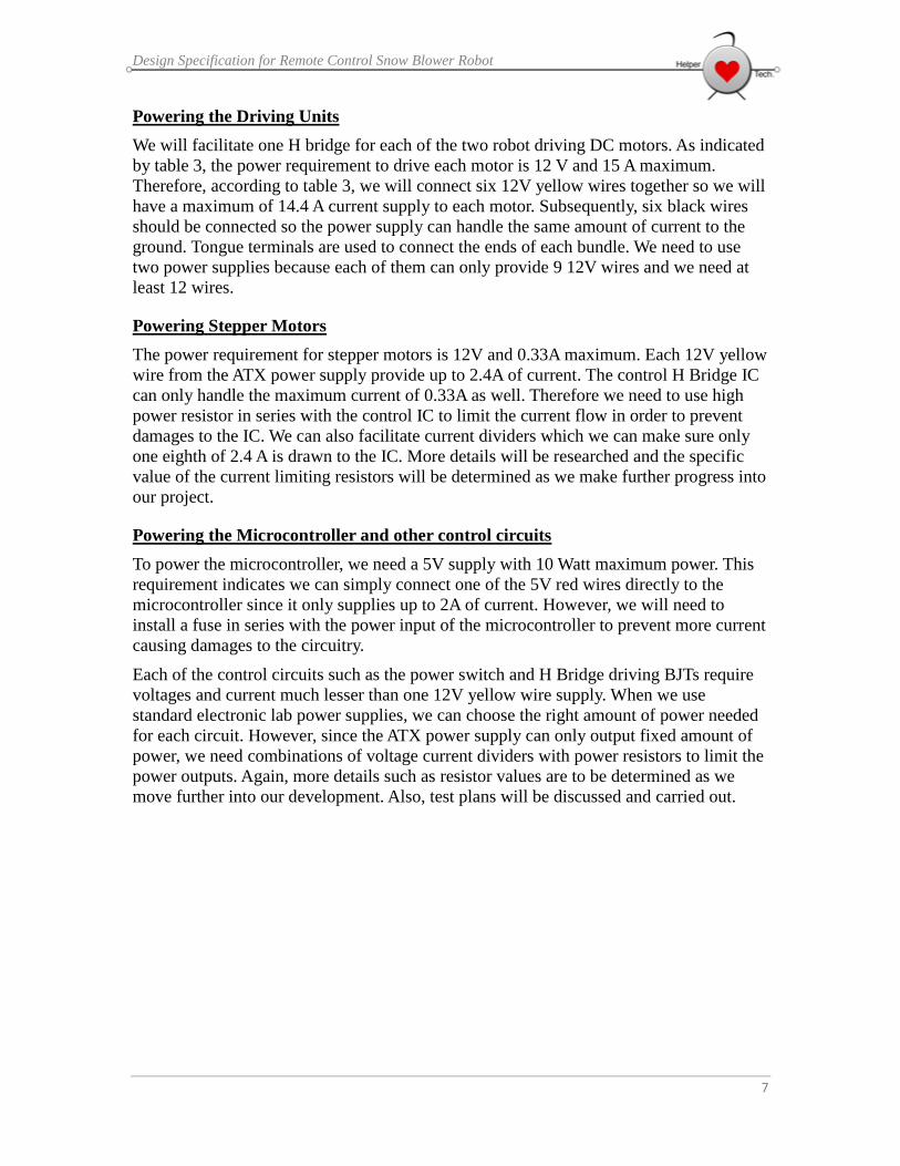
2.4 Driving Unit The driving unit is responsible of the movement of our RoboBlow robot. Two geared DC
motors are used in this module. Control signals are inputted from the on board
microcontroller to control the speed and the direction of these motors. The two Bridges
act as the interface to between power, control signals and the motors. The figure in below
illustrates this relationship.
H Bridge
Control Signals
Power Supply
DC motor with Gear
BoxWheel Rotation
Figure 5: Driving Unit Module
2.4.1 Physical and Mechanical Design
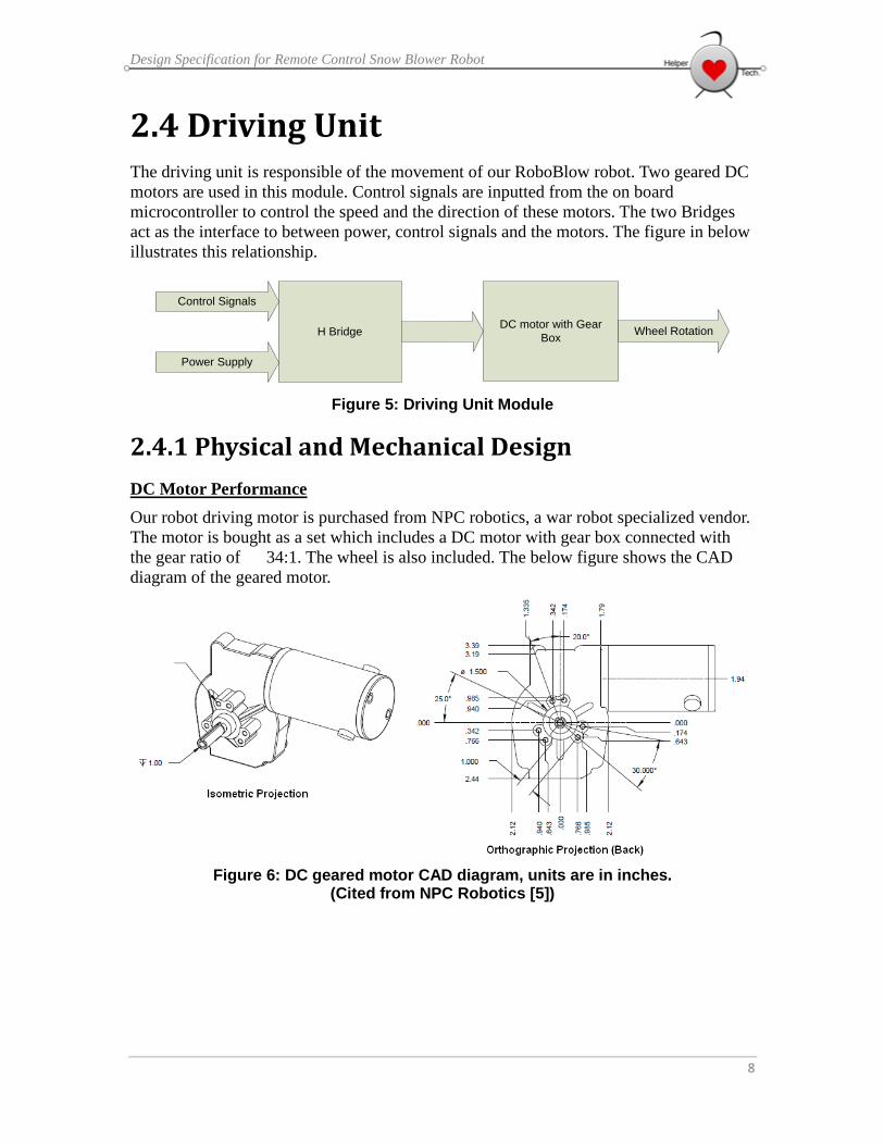
DC Motor Performance
Our robot driving motor is purchased from NPC robotics, a war robot specialized vendor.
The motor is bought as a set which includes a DC motor with gear box connected with
the gear ratio of 34:1. The wheel is also included. The below figure shows the CAD
diagram of the geared motor.
Figure 6: DC geared motor CAD diagram, units are in inches. (Cited from NPC Robotics [5])

Design Specification for Remote Control Snow Blower Robot
9
Since the DC motor is already geared, the torque the shaft outputs is increased, but the
speed of the rotation is decreased which suits our application where higher torques are
needed. The table below shows the performance of the geared motor output with respect
to various current supplied.
Table 5: Torque, RPM and amperage relationship @ 12V [5]
Material of the Wheel
The wheel of our robot is included in the set with the geared motors. The diameter is 8”
long and the width is about 0.8” wide. The surface of the wheel is smooth and made of
rubber which would not be sufficient for our robot to drive in icy conditions. Therefore,
we plan to cut two pieces of strips from a slip proof mat of width 0.8” and length of 25”
and use superglue to attach them to our wheels. There might be alternative solutions to
improve the traction of our wheels. More details will be addressed as we make further
progress into this module.

Design Specification for Remote Control Snow Blower Robot
10
2.4.2 Electronic Design
In order to rotate our motors in two directions, we need to implement an H-bridge circuit
for each of them. The figure below presents the schematic of a standard H bridge [6].
Figure 7: H-Bridge Schematic
The goal of an H-bridge circuit is to supply electrical power to motors in two directions
so the motor can be rotated in either counter clockwise or clockwise direction. The theory
of operation is fairly simple. From the above figure, when control signal 1 and 4 switch
on the Q1 and Q4 transistors while the Q2 and Q3 transistors stay off, Q4 will source
current to the motor while Q1 sinks the current to the ground. In order to reverse the
rotation of the motor, control signals switch on Q2 and Q3 transistors while Q1 and Q4
transistors are turned off. D1 to D4 are flyback diodes. Their main purpose is to prevent
sudden voltage change applied across inductive loads in order to protect the transistors
from damages caused by excess current. The table below presents the basic components
we will use to build our H-bridge circuit.
Table 6: Basic Components in H-Bridge Component: Device: Description:
Q4, Q2 IRF 9540 N-channel Power MOSFET
Q1, Q3 IRF 540 P-channel Power MOSFET
D1 to D4 (might not be
used)
1N4001 Flyback diodes
BJT on control signal
(not shown)
2N3904 General Purpose NPN BJT
M1 NPC-41250 DC Geared Motor

Design Specification for Remote Control Snow Blower Robot
11
The four power MOSFETs selected are mainly used for high power applications which
can handle current up to 22A. Since we plan to supply 15 A to our motor, these transistors
are suitable for our purpose. The control signals outputted by our microcontroller are 5V
and 40mA maximum when they are digitally HIGH. Therefore, we might have to add a
general purpose bipolar junction transistor on each control signal in order to amplify
these signals in order to sufficiently turn on either set of the power transistor. Specific
details of this issue will be researched and addressed as we make further progress into
this module. The flyback diodes might not be needed in our H bridge circuit because
these diodes are already fabricated with the power transistors.
One of the most important concerns of our H-bridge circuit is the power generated from
the transistors during operation. This power can be estimated using equation:
Where Id is the drain current, and Rds(on) is the resistance between drain and source
when the transistor is conducting. According to data sheet, the Rds(on) is about 0.055 to
0.077 ohm. We will use 0.066 ohm as estimation and take the drain current to be 16 A,
and we could find the power generated would be about 17 Watt. Based on the
calculation, we would need to add heat sinks in order to dissipate the heat generated.
The figure below shows how the heat sink is added to the power transistor. The insulating
Mica is placed on the metal plate of the transistor so the heat sink is insulated. The
washer is used to provide electrical insulation to the screw.
Figure 8: adding Heat Sink to the power transistor

Design Specification for Remote Control Snow Blower Robot
12
2.5 Safety Design Safety is the most important factor when it comes to designing a product. Roboblow is
targeted to bring convenience to people’s life. Despite its main task which is to clean the
snow, It should not make damages to any properties or cause injuries to any life form by
any means.
There are two cameras installed on the robot, one monitoring the front, and the other one
can be rotated wirelessly by the operator. When the operator sees any incoming danger of
operation, he/she can shut down the onsite robot remotely through the wireless controller.
However, there should be other safety mechanism on the robot itself, so other people can
be warned or directly shut down the robot when troubles are about to happen. We have
planned three mechanisms that would help dealing with these safety issues.
Flashing LEDs during Operation
We plan to use four LEDs so that two of them will be flashed for a second whenever the
microcontroller on board is powered on. The colors of LEDs have to be in bright tones
such as yellow and red so people nearby the area can notice the machine is in operation.
The figure below illustrates how the LED flashing circuit will be connected. When digital
output1 is HIGH, the two LEDs at the top are lighted, and vice versa for the bottom two
LEDs. The two resistors are implemented in order to limit the current. Specific resistor
values and LED colors will be decided as we make further progress into our safety
module.
Figure 9: Flashing LED using microcontroller

Design Specification for Remote Control Snow Blower Robot
13
Motion Detection for Warning Alarm
Although there are two cameras installed on the robot with one able to rotate, there are
still plenty of blind spots when the robot is in operation. Therefore, we need to add other
sensors on the robot in order to monitor the surrounding so warnings can be given to live
forms nearby. We plan to install three motion sensors on our robot, so all sides of the
machine can be monitored except for the front side where there is always a camera
looking forward.
Motion SensorsSensor
SignalsMicrocontroller
Control
SignalsAlarm
Figure 10: Motion Detection for Warning Alarm
According to the above diagram, the motion sensors installed on our robot will send
signals to the on board microcontroller whenever any motion is detected from the
surroundings. Once the microcontroller receives any of the sensor signals, it will send
control signal to sound the alarm so live forms nearby can be warned. We will use PIR
motion sensors and adequate electronic alarm to construct our circuit.
Button-Triggered Emergency Power Off
This mechanism is relatively simple to be achieved and is also one of the most crucial
functions on our robot. A red button with very noticeable sign will be installed on the
cover of our robot, so whenever it is pressed, the robot under operation will be shut down
and power off immediately. At the hardware level, we simply have to connect the button
to the microcontroller and label the button clearly on the cover of our robot. At the
software level, there will be an if-statement checking the status of the button before each
loop with other functions is executed.

Design Specification for Remote Control Snow Blower Robot
14
2.6 Test Plan Power Switch Test Plan
Turning the switch between NO and NC nodes in relay contacts
Since we have no previous experience with a relay, we first start by checking if the relay
purchased works according to its description. We connect the two ends of the relay coil to
the power supply in our electronics lab with minimum current and gradually increase the
voltage on. There are no connections to the relay contacts. As soon the voltage reaches 8V,
the switch inside the relay clicks to another side of the two contacts. Therefore, we
conclude that we only need 8V to switch on the relay.
Connect the circuit according to the diagram with LED as load instead of motor
Figure 11: Testing the power switch circuit with low power application
After making sure our relay works according to its description, we then connect the
switch circuit like above. We use a LED instead of the AC motor, and Vdc with ~1V from
the power supply in our lab with minimum current to make sure our switch circuit works
according to the theory before we actually put the high power application on site. Upon
connecting the necessary circuit components and apply adequate voltages for the switch
circuit and Vdc, we observe the LED turning on/off according to the digital control signal
given by the microcontroller.

Design Specification for Remote Control Snow Blower Robot
15
3. Snow-out Direction Unit
3.1 Physical and Mechanical Design To control the snow blowing direction, we use a DC stepper motor attaching to the handle on the
body of the snow thrower to turn the snow direction vanes on the thrower. To ensure that the vane
can rotate full range without breaking the limit (the vane has its physical limit that it can only
rotate to a certain instance.) we need to carefully select the initial position of the motor and the
range of degree that the handle rotates within 90 to prevent breaking.
The following diagram shows the snow thrower vane that is controlled by the motor (The handle
is hidden behind the vane, inside the robot body.) The following diagram shows the vane that
controls the snow blowing direction.
Figure 12: Snow Thrower and the Vane
Stepper Motor
We need to choose a stepper motor that has sufficient torque to apply force to rotate the
handle. Since the motor is attached to the end of the handle, it needs much more force to
drive. We choose a Sm-42b-yg011-25 mercury stepper motor to serve this purpose. The
bipolar motor is driven by a L293dne IC chip. The following diagram shows the
connection between IC, motor, and the Arduino microcontroller. Note that Arduino MCU
is only used for testing.
Figure 13: Stepper Motor
The motor has four colored wires that are blue, green, red, and yellow, respectively.

Design Specification for Remote Control Snow Blower Robot
16
3.1.1 Control Circuit
The following diagram shows the PCB connection of the L293N IC and the motor, where
RA0 is Blue, RA1 is yellow, RA2 is green, and RA3 is red.
Figure 14: PCB connection of the L293N IC and the motors
The mechanism we use is standard full-step iteration. Since precision is not highly
required for this application, half-step iteration is not used. The bipolar step motor is
consisting of two electromagnets. The red and green wire controls one magnet and need
to be always inverted to each other, while the blue and yellow wire controls another one
and need to be always inverted to each other.
To control the above circuit by microcontroller, we apply positive or negative digital
signals to the pins 1Y, 2Y, 3Y, and 4Y by a specific order. The order can be summarized
by the following table:
Table 7: Pin signal sequence for snow-out direction
1Y 2Y 3Y 4Y
+ - - +
- + - +
- + + -
+ - + -
“+” stands for positive digital signals
“-” stands for negative digital signals
We keep looping the signal order and insert a delay of 75ms between the iterations. ach
iteration would cause the motor to rotate .8 ˚. When applying the order reversely, the
motor would rotate in reverse direction.

Design Specification for Remote Control Snow Blower Robot
17
3.1.2 Method of attaching
To make the motor apply force to the handle, we screw a hole on the handle, stick a metal
rod inside the hold, then attach the metal rod and the end of the handle to the top of the
motor.
To ensure that the motor is properly attached to the handle, we choose to use the
electrical glue gun.
3.2 Camera Unit
3.2.1 Physical design
In order to be able to constantly check the surrounding environment 360 degrees wise, we
need two USB cameras on the robot. Camera A is mounted on top of a robot and is able
to rotate 360˚(controlled by another stepper motor used for controlling the snow blowing
direction). Camera B is mounted solid in the front of the robot as the picture shows below,
and has no freedom to rotate. Camera B is used to constantly monitor images in front of
the robot to the ground to ensure safety. The cameras are securely placed outside the
robot, and covered by acrylic boards which are two centimeters thick. We also install a
transparent glass shield in front of the camera to make it possible to be used under snow
and wet condition.
Figure 15: Camera location in the robot

Design Specification for Remote Control Snow Blower Robot
18
3.2.2 Camera
We choose Webcam camera SPCA5xx by Vimicro Corp for both of our camera. This
camera supports Linux kernel and can be configured to send real time image to the
central MCU on the robot, where the MCU on the robot sends the image back to the LCD
screen for the user to monitor. Below is an image of SPCA5xx, a stable, high quality
webcam camera.
3.2.3 Step Motor Connection
We use the same mechanism and step motor as described in the snow blowing direction
section. To connect the camera to the motor, we make use of the cylinder acrylic rod,
which is hollow in the interior. We insert a solid rod from the interior, connect the camera
on one end via superglue, and connect the other end on the top of stepper motor by
electrical glue gun. This application requires precise rotating degree, hence, we employ
the half-stepping technique of stepper motor. To look at the reference diagram of stepper
motor connection again:
Figure 16: PCB connection of the L293N IC and the motors

Design Specification for Remote Control Snow Blower Robot
19
We give 1/0 digital signals to 1Y, 2Y, 3Y and 4Y according to the following table of
order:
Table 8: Pin signal sequence for camera direction
Step 1Y 2Y 3Y 4Y
1 + - - -
2 + + - -
3 - + - -
4 - + + -
5 - - + -
6 - - + +
7 - - - +
8 + - - +
This technique has twice as many as steps comparing to the standard technique used in
controlling the thrower vane. This way, the resolution is double and each step rotate the
motor 0.9 degree, hence increase the precision.

Design Specification for Remote Control Snow Blower Robot
20
4. Salt Spraying Unit
4.1 Physical and Mechanical Design The salt spraying unit serves the purpose of spraying salt on the areas that the robot goes
through. The unit is placed under the bottom of the robot. The important issues we need
to consider is how to control the amount of salt carefully so we don’t waste salt or runs
out of salt too fast. Second of all, we want to limit out budget and design complicity on
this part as much as possible. Therefore, using another stepper motor is not in our
consideration for this case. The design can be broken into 3 parts: The salt box, the salt
stopper, and the salt filter. The box containing the salt needs to be made of material that
doesn’t easily conduct heat to prevent the salt from melting. The box should at the same
time be waterproof. We choose to make the box with plastic. The box should be
30cmx40cm to contain 1.2 liters of salt.
4.2 The Salt Stopper As above graph illustrates, we drill a hole at the bottom of the plastic box and put a
stopper at the hole to fill the hole. We want to be able to control the stopper with
microcontroller. The design we think of is that we use an electromagnet to be the salt
stopper, and place one permanent magnet at the top of the box and superglue another one
below the hole on top of the salt filter. If we configure it that way, When the Salt
Spraying unit is off, counter-clock wise current is applied by the microcontroller, to force
the filter end to become N polar, hence is forced to touch the magnet at the top of filter
and filled the hole. When the unit is on, the current is applied reversely and the top end is
forced to be N polar, hence the stopper touches the top and leave the hole by a tiny
amount, allowing salt to go through holes and spray through the filter. The following
graph shows the electromagnet we are going to use
Figure 17: Electromagnet

Design Specification for Remote Control Snow Blower Robot
21
4.3 The Salt Filter We want the filters to have as small holes as possible which would be just a little bit
bigger than a single salt. We choose to use the stainless-steel filter for tea set for our salt
filter. To prevent from wasting salt, the enable of the microcontroller signal is attached to
the wheel motor signals so that whenever the robot is not moving, the salt spraying unit
always stops spraying. The magnet we are using is one standard medium round craft
magnet. If applied enough current to the electromagnet, this magnet would have enough
magnetic force to attract/repel the electromagnet even with the resistance from the salt.
The same magnet is attached to the top of the box to form a switch for the stopper. The
following graph shows the tea set filter and the medium round magnet.
Figure 18: Tea set filter

Design Specification for Remote Control Snow Blower Robot
22
5. The Entire Body Building
5.1 Physical Design The robot needs to overcome snow condition hence there is no doubt it needs to be
waterproof. While we are driving the robot with only two NPC motors, the weight of the
robot is going to be another issue. The robot functions in best efficiency when the totally
weight is at around 60 pounds. Considering the weight and the waterproof issue, we
choose acrylic board for our body material. We can get the acrylic boards from industrial
plastic and paints. Another choice would be that to build the body of aluminum, which is
light and waterproof, too. We can bring our design to a local welding company, where
they can fabricate the body in aluminum. As the following graph illustrates, the body is
more like a square box, with the back cut to fit in the wheels. All of our design circuitry
and motors are well hidden inside the body.
Figure 19: Physical design of the robot
The above graph is the right side view of the robot. The yellow part is the body of the
robot. We might install a pair of small decorative wheels at the front of the thrower to
reduce the friction.

Design Specification for Remote Control Snow Blower Robot
23
5.2 Method of Connection To make sure the body is attached solidly, we take the body to the machine shop in Simon
Fraser University, drill holes in them and use screws to connect the body. The reason we
want to use screw instead of electrical glue gun is because it’s easier to repair if we can
open the body easily. The body needs to connect to the thrower perfectly to ensure proper
functionality.
5.3 Partition in the Bottom Board To place the component, circuitries and power supply solidly inside the body, we need a
mechanism to ensure that they don’t move around. We partition the bottom body by
installing acrylic board boundaries. The parts consist of 2 motor blocks, one power
supply block, one cylindrical block (for the upper camera), two stepper motor blocks,
MCU block and circuit blocks. The concept is illustrated in the following graph.
text
NPC WHEEL MOTOR NPC WHEEL MOTOR
STEPPER MOTOR FOR
CAMERA
POWER SUPPLY
STEPPER MOTOR FOR
VANE
MCU
textPCB
CIRCUITRY
text
text
PCB CIRCUITRY
PCB CIRCUITRY
PCB CIRCUITRY
Figure 20: Partition in the Bottom Board

Design Specification for Remote Control Snow Blower Robot
24
6. Remote controller The design specification of the remote controller will be provided from physical design,
hardware design and software design aspects. In physical design, the controller
dimension, weight and material will be stated. It will also provide internal structure of the
controller which includes the detailed information of the different hardware as well as
their inside positions. In order to make this demonstration easier, the SolidWork graph of
the controller will be shown in the physical design subsection. In hardware design, each
hardware information and its functions will be presented. It also provides how each
hardware interacts with others. In software design aspect, the embedded software
architecture will be given. This includes the software working mechanism and the
algorithm of each process.
6.1 physical design specification For the ease of understanding this section, please refer to the figure 21 and figure 22.
Figure 21: the remote controller with cover opened.
Figure 22 the remote controller with the cover closed

Design Specification for Remote Control Snow Blower Robot
25
6.1.1 Dimension, weight and material
The shape of the controller is a rectangular block. The length is 330mm, the width is
190mm and the height is 45mm. The weight is less than 1 kg. We make this size and
weight mostly for the portable consideration. When user is controlling the joystick, the
base of the controller should be able to provide enough fictions so that it will not slip
with the human operation. Thus at the bottom of the controller, there will be four rubbers
at four corners to increase the fiction. The cover of the controller will be made by Acrylic,
because Acrylic material can provide enough strength. Its density is suitable. It is also
very cheap.
6.1.2 Controller panel design
The control panel layout is shown in figure 23. The button distribution is design based on
the controller panel convention, function importance and ease of controlling. In addition,
buttons controlling the same module are arranged together. The joystick is positioned at
right side of the controller which is designed for right-handed user. We also have the
similar design for left-handed user. The only difference from right-handed design is that
the positions of the joystick and buttons are switched. A 5.6 inches LCD screen used to
display the real-time image from camera is located in the middle area of the controller.
The speed display is right beside the screen.
Figure 23: the top-view of the remote controller

Design Specification for Remote Control Snow Blower Robot
26
Table 9: All the buttons on the control panel as well as their functions.
Button functions
A Camera switch
B Switch the camera view
C Rotate camera counter-clockwise
D Rotate camera clockwise
E Snow out direction rotate counter-clockwise
F Snow out direction rotate clockwise
G Snow blower switch
H Salt spraying switch
I Power switch for controller
J Emergency switch
K High speed
L Low speed
6.1.3 Internal structure
The ARM development board, USB breadboard and WIFI module are placed and fixed
inside the controller. USB breadboard and WIFI module are both connected to the ARM
development board. Buttons and joystick are connected to the USB breadboard. LCD
screen, LEDs and seven segment display are connected to ARM development board.
6.2 Hardware design specification ARM development board is the central processing unit of the controller. It is responsible
for collecting all the user inputs, data received from WIFI module. It is also designed to
process all the data it received and send out the proper commands. Linux OS has already
been built in. The kernel version is 2.6.12. It enables us to use multi-process/threads
programming skills when writing the embedded software. The RAM is 64MB which is
enough for our products.
USB breadboard connected to the buttons belongs to USB HID class. It will recognize
the inputs from user and send the corresponding USB format data to ARM MCU. The
driver for this device can be found in Linux kernel, the dynamically module installation
method is chosen for mounting this device.
WIFI module (802.11g) is also connected to ARM board by USB. It receives the data
from robot and send out the command issued by ARM MCU in the controller. The
effective wireless communication distance is 100-150 meters depending on environment
situation. Considering that the usage of the robot is mainly for family, this
communication distance is enough for our products. The device driver can be
downloaded from manufacturer’s website. The dynamically module installation method
is chosen for mounting this device.
Buttons and Joystick are directly connected to the USB breadboard. Joystick has eight

Design Specification for Remote Control Snow Blower Robot
27
directions (forward, left forward, right forward, backward, left backward, right backward,
left and right).
LCD screen is connected to ARM development board. The driver is built inside the Linux
kernel.
LEDs and seven segment display are connected to I/O extension port in ARM
development board. The driver is created by our team. The dynamically module
installation method is chosen for mounting this character device.
6.3 Software design specification
6.3.1 Driver development
I/O extension driver is developed by our team. It is used to assign a single pin to be high
or low voltage at a time. The driver specification is stated as following:
1. The device is registered as character device. The device name is ioext.
2. Once the device is opened, all the pins will be set as low voltage. All pull up
resistors associate with the pins will be set.
3. The pins can be set as input or output pins by ioctl function.
4. Before writing to/read from a pin, that pin must be first configured as
output/input pin by using ioctl function.
5. The pin can be read by using read() function.
6. The pin can be write by using write() function.
Note that the complete API will not be provided as it is under development.

Design Specification for Remote Control Snow Blower Robot
28
6.3.2 Software architecture in Nutshell
Figure 24 the software architecture in the controller
As indicated in the nutshell graph, there are 3 main processes in our embedded software.
Process A has 3 threads. Thread 1 is continuously detecting the input from USB buttons
and joystick. Thread B does the I/O extension pin assignments according to the output
from thread 1, so that LEDs and 7 segment display can works properly. Thread 3 is used
to send the command obtained from user input to the WIFI module which will be
transferred to the robot wirelessly later on. Since WIFI communication usually has more
time delay, FIFO inter-process communication method will be used to communication
with WIFI process (process B). Process B is WIFI process. It is used to read/write to the
WIFI module. Reading WIFI module means getting the data received from WIFI while
writing WIFI module means sending data to the robot. This module will accept the data
from FIFO that connects to process A. It will also transfer the camera image data to LCD
process (process C) via another FIFO. LCD process is responsible to decode the camera
image data and display it on the LCD screen. Note that process B and process C are also
controlled by process A via signal mechanism.
6.3.2 Algorithm flow chart
Processes and threads algorithm can be found in appendix. The following table indicates
the appendix indexes for each process and thread.
Table 10: Appendix index for each process and thread
Process or thread name Appendix index
Thread 1 (Process A) Appendix 3
Thread 2 (Process A) Appendix 4
Thread 3 (Process A) Appendix 5
Process B Appendix 6
Process C Appendix 7

Design Specification for Remote Control Snow Blower Robot
29
6.4 Control module inside the robot The controlling module can be divided into two parts, hardware design and software
design. In hardware design, MCU, WIFI module and camera as well as other devices will
be introduced. In software design, the embedded software algorithm will be presented.
6.4.1 Hardware design
The MCU used inside the robot is the same as the one in the controller. It is responsible
for receiving commands from controller and sending the corresponding commands to the
robot. The pins in I/O extension port will be connected to the control circuit of the actual
module. By controlling the transistor base voltage, the motor or other component can be
switched on and off. The pin assignment can be found in the appendix 1 and 2. The I/O
extension driver is created by our team members. The dynamically module installation
method is chosen for mounting this device.
The WIFI module used inside the robot is the same as the one in the controller. It is
connected to MCU by USB port. It is responsible for transmitting camera image to the
controller and receiving the data from controller.
There are 2 cameras installed on the robot. The cameras are connected to the MCU by
USB port. The driver is already inside the Linux OS.
6.4.2 Software design specification
6.4.2.1 Software architecture in nutshell
Figure 25: Software architecture in the robot
As indicated in the nutshell, there are 3 processes. Process A is WIFI process; it receives
the data transmitted from the controller and send camera data to the controller. The

Design Specification for Remote Control Snow Blower Robot
30
received data will be further sent to the process B which consists of 3 threads. Thread 1 is
used to receive the data from process A. Thread 2 does the pin assignment according to
the received data. Thread 3 detects all the sensors states installed on the robot. If
emergency situation occurs, it will stop all the working components in the robot and send
emergency signal to controller. Process C collets the real-time image captured from two
cameras and sends the data to process B.
6.4.2.2 Algorithm flow chart
Processes and threads algorithm can be found in appendix. The following table indicates
the appendix indexes for each process and thread.
Table 11: Appendix index for each process and thread
Process or thread name Appendix index
Thread 1 (Process B) Appendix 8
Thread 2 (Process B) Appendix 9
Thread 3 (Process B) Appendix 10
Process A Appendix 11
Process C Appendix 12
7 Conclusion This document has discussed the technical design solutions to meet the RoboBlow
functional specifications as well as listing the hardware parts which are possible to be
used in the product. The prototype of Roboblow is expected to be realized by following
the designed specifications and test plans in this document.

Design Specification for Remote Control Snow Blower Robot
31
8 Appendix Appendix 1:
I/O extension pin assignment for MCU in the robot
I/O extension pin number Associated CPU I/O pin Function
PIN#1 GPE11 Power MOSFET #1 gate
voltage control for robot left
wheel H-bridge
PIN#2 GPE12 Power MOSFET #2 gate
voltage control for robot left
wheel H-bridge
PIN#3 GPE13 Power MOSFET #3 gate
voltage control for robot left
wheel H-bridge
PIN#4 GPG2 Power MOSFET #4 gate
voltage control for robot left
wheel H-bridge
PIN#5 GPG3 Power MOSFET #1 gate
voltage control for robot right
wheel H-bridge
PIN#6 GPG5 Power MOSFET #2 gate
voltage control for robot right
wheel H-bridge
PIN#7 GPG6 Power MOSFET #3 gate
voltage control for robot right
wheel H-bridge
PIN#8 GPG7 Power MOSFET #4 gate
voltage control for robot right
wheel H-bridge
PIN#9 GPG11 H-bridge Power MOSFET #1
gate voltage control for salt
spraying motor
PIN#10 GPB0 H-bridge Power MOSFET #2
gate voltage control for salt
spraying motor
PIN#11 GPB9 H-bridge Power MOSFET #3
gate voltage control for salt
spraying motor
PIN#12 GPB1 H-bridge Power MOSFET #4
gate voltage control for salt
spraying motor
PIN#13 GPB5 Snow blower power switch
control
PIN#14 GPB6 H-bridge Power MOSFET #1
gate voltage control for snow
out direction motor
PIN#15 GPB8 H-bridge Power MOSFET #2
gate voltage control for snow

Design Specification for Remote Control Snow Blower Robot
32
out direction motor
PIN#16 GPB10 H-bridge Power MOSFET #3
gate voltage control for snow
out direction motor
PIN#17 GPA21 H-bridge Power MOSFET #4
gate voltage control for snow
out direction motor
PIN#18 GPB7 H-bridge Power MOSFET #1
gate voltage control for
camera rotation motor
PIN#19 AIN0 NULL
PIN#20 AIN1 NULL
PIN#21 AIN2 NULL
PIN#22 AIN3 NULL
PIN#23 GPF0 H-bridge Power MOSFET #2
gate voltage control for
camera rotation motor
PIN#24 GPF2 H-bridge Power MOSFET #3
gate voltage control for
camera rotation motor
PIN#25 GPF3 H-bridge Power MOSFET #4
gate voltage control for
camera rotation motor
PIN#26 GPF4 NULL
PIN#27 IIC SDA NULL
PIN#28 IIC SCL NULL
PIN#29 VCC NULL
PIN#30 GND Ground

Design Specification for Remote Control Snow Blower Robot
33
Appendix 2:
I/O extension pin assignment for MCU in the controller
I/O extension pin number Associated CPU I/O pin Function
PIN#1 GPE11 Power button LED
PIN#2 GPE12 Emergency button LED
PIN#3 GPE13 Camera on/off LED
PIN#4 GPG2 Snow blower switch LED
PIN#5 GPG3 Salt spraying switch LED
PIN#6 GPG5 Robot Speed level 1 LED
PIN#7 GPG6 Robot Speed level 2 LED
PIN#8 GPG7 7 segment display
PIN#9 GPG11 7 segment display
PIN#10 GPB0 7 segment display
PIN#11 GPB9 7 segment display
PIN#12 GPB1 7 segment display
PIN#13 GPB5 7 segment display
PIN#14 GPB6 7 segment display
PIN#15 GPB8 7 segment display
PIN#16 GPB10 NULL
PIN#17 GPA21 NULL
PIN#18 GPB7 NULL
PIN#19 AIN0 NULL
PIN#20 AIN1 NULL
PIN#21 AIN2 NULL
PIN#22 AIN3 NULL
PIN#23 GPF0 NULL
PIN#24 GPF2 NULL
PIN#25 GPF3 NULL
PIN#26 GPF4 NULL
PIN#27 IIC SDA NULL
PIN#28 IIC SCL NULL
PIN#29 VCC NULL
PIN#30 GND Ground

Design Specification for Remote Control Snow Blower Robot
34
Appendix 3:
Algorithm flow chart of thread 1 in process A for software in controller MCU

Design Specification for Remote Control Snow Blower Robot
35
Appendix 4:
Algorithm flow chart of thread 2 in process A for software in controller MCU

Design Specification for Remote Control Snow Blower Robot
36
Appendix 5:
Algorithm flow chart of thread 3 in process A for software in controller MCU

Design Specification for Remote Control Snow Blower Robot
37
Appendix 6:
Algorithm flow chart of process B for software in controller MCU

Design Specification for Remote Control Snow Blower Robot
38
Appendix 7:
Algorithm flow chart of process C for software in controller MCU

Design Specification for Remote Control Snow Blower Robot
39
Appendix 8:
Algorithm flow chart of process A for software in robot MCU

Design Specification for Remote Control Snow Blower Robot
40
Appendix 9:
Algorithm flow chart of thread 1 in process B for software in robot MCU

Design Specification for Remote Control Snow Blower Robot
41
Appendix 10:
Algorithm flow chart of thread 2 in process B for software in robot MCU

Design Specification for Remote Control Snow Blower Robot
42
Appendix 11:
Algorithm flow chart of thread 3 in process B for software in robot MCU

Design Specification for Remote Control Snow Blower Robot
43
Appendix 12:
Algorithm flow chart of process C for software in robot MCU

Design Specification for Remote Control Snow Blower Robot
44
9 References [1] Snow Thrower, [Online] Available:
http://www.canadiantire.ca/AST/browse/2/OutdoorLiving/PowerEquipment/Snowthrowe
rs/PRDOVR~0603982P/Yardworks%252B9A%252B%25252B%252B16-in%252BElectr
ic%252BSnow%252BThrower.jsp?locale=en [Accessed: Mar 13th, 2011]
[2] Power Switch Circuit, [Online] Available:
http://www.kpsec.freeuk.com/trancirc.htm [Accessed: Mar 13th, 2011]
[3] Power Extension Cord, [Online] Available:
http://www.canadiantire.ca/AST/browse/3/HouseHome/2/Electrical/OutdoorPowerCords/
PRDOVR~0522321P/Contractor%252BGrade%252BPower%252BBlock%252BCord%2
52B12%25252B3.jsp?locale=en [Accessed: Mar 13th, 2011]
[4] Converting ATX Power Supply, [Online] Available:
http://www.instructables.com/id/Convert-an-ATX-Power-Supply-Into-a-Regular-DC-Pow
e/#step1 [Accessed: Mar 13th, 2011]
[5] Driving unit DC motor, [Online] Available:
http://www.npcrobotics.com/products/viewprod.asp?prod=40&cat=20&mode=gfx
[Accessed: Mar 13th, 2011]
[6] H-Bridge Circuitry. [Online] Available:
http://www.robotroom.com/BipolarHBridge.html [Accessed: Mar 13th, 2011]
[7] Bipolar Step motor operation theory. [Online] Available:
http://www.imagesco.com/articles/picstepper/02.html [Accessed: Mar 13th, 2011]
[8] Resource of SPCA5xx webcam by Vimicro Corp. [Online] Available:
http://www.unixresources.net/linux/lf/11/archive/00/00/16/40/164005.html
[Accessed: Mar 13th, 2011]