Embed Size (px)
Citation preview

uDirect®
User GuideVersion 4.6

Notices© 2009 XMPie® Inc. All rights reserved. U.S. Patents 6948115, 7406194, 7548338 and pending patents.
uDirect® Version 4.6 User Guide, Document Revision: 1.16.2.4, August 2009
For information, contact XMPie Inc. 767 Third Avenue (at 48th Street), 3rd Floor New York, NY 10017, USA Tel: 212 479 5166, Fax: 212 888 2061, Technical Support: 212 888 2050
More information can be found at www.xmpie.com
XMPie provides this publication "as is" without warranty of any kind, either express or implied. This publication may contain technical inaccuracies or typographical errors. While every precaution has been taken in the preparation of this document, the publisher and author assume no responsibility for errors or omissions. Nor is any liability assumed for damages resulting from the use of the information contained herein. Changes are periodically made to the information herein; these changes will be incorporated in new editions of the publication. XMPie may make improvements and/or changes in the product(s) and/or the program(s) described in this publication at any time.
ADOR, PersonalEffect, uChart, uCreate, uDirect, uEdit, uImage, uPlan, uProduce, uStore, X-DOT, XLIM, XMPie, the XMPie logo, and the slogan “one to one in one” are trademarks and/or registered trademarks of XMPie Inc. its subsidiaries, and/or affiliates in the United States and/or other countries. All other company or product names are the trademarks or registered trademarks of their respective holders. All rights not expressly granted are reserved.
Adobe Acrobat, Adobe Dreamweaver, Adobe Illustrator, Adobe InDesign, and Adobe Photoshop are trademarks of Adobe Systems Incorporated.
SQL Server 2005, Windows Server 2003, Windows Server 2008, Windows Vista, and Windows XP are trademarks or registered trademarks of Microsoft Corporation.
Mac OS is a trademark of Apple Computer, Inc.
ComponentArt is a trademark of ComponentArt Inc.
Other trademarks and service marks are the property of their respective owners.

Contents iii
Contents
Preface . . . . . . . . . . . . . . . . . . . . . . . . . . . . . . . . . . . . . . . . . . . . . . . xviAudience . . . . . . . . . . . . . . . . . . . . . . . . . . . . . . . . . . . . . . . . . . . . . . . . . . . . . . . . . . . . . . . xvi
uDirect Licensing . . . . . . . . . . . . . . . . . . . . . . . . . . . . . . . . . . . . . . . . . . . . . . . . . . . . . . . . . xvi
About XMPie . . . . . . . . . . . . . . . . . . . . . . . . . . . . . . . . . . . . . . . . . . . . . . . . . . . . . . . . . . . . xvi
Other XMPie Products . . . . . . . . . . . . . . . . . . . . . . . . . . . . . . . . . . . . . . . . . . . . . . . . . . . . . xvii
What’s in this Guide . . . . . . . . . . . . . . . . . . . . . . . . . . . . . . . . . . . . . . . . . . . . . . . . . . . . . . xvii
Contacting XMPie . . . . . . . . . . . . . . . . . . . . . . . . . . . . . . . . . . . . . . . . . . . . . . . . . . . . . . . . xviii
Chapter 1: Introduction to uDirect . . . . . . . . . . . . . . . . . . . . . . . . . . . 1uDirect Standard . . . . . . . . . . . . . . . . . . . . . . . . . . . . . . . . . . . . . . . . . . . . . . . . . . . . . . . . . . . . . 1
uDirect Designer. . . . . . . . . . . . . . . . . . . . . . . . . . . . . . . . . . . . . . . . . . . . . . . . . . . . . . . . . . . . . . 3
uDirect professional . . . . . . . . . . . . . . . . . . . . . . . . . . . . . . . . . . . . . . . . . . . . . . . . . . . . . . . . . . . 3
uDirect Studio . . . . . . . . . . . . . . . . . . . . . . . . . . . . . . . . . . . . . . . . . . . . . . . . . . . . . . . . . . . . . . . 3
Installation and Upgrades from Previous Versions . . . . . . . . . . . . . . . . . . . . . . . . . . . . . . . . . . . . . . 4
Hardware and Software Requirements . . . . . . . . . . . . . . . . . . . . . . . . . . . . . . . . . . . . . . . . . . . 4
Windows . . . . . . . . . . . . . . . . . . . . . . . . . . . . . . . . . . . . . . . . . . . . . . . . . . . . . . . . . . . . . . . . 4
Macintosh . . . . . . . . . . . . . . . . . . . . . . . . . . . . . . . . . . . . . . . . . . . . . . . . . . . . . . . . . . . . . . . 4
General Requirements . . . . . . . . . . . . . . . . . . . . . . . . . . . . . . . . . . . . . . . . . . . . . . . . . . . . . . 4
Before Starting the Installation . . . . . . . . . . . . . . . . . . . . . . . . . . . . . . . . . . . . . . . . . . . . . . . . 5
Installing or Upgrading uDirect . . . . . . . . . . . . . . . . . . . . . . . . . . . . . . . . . . . . . . . . . . . . . . . . 5
Activating your uDirect License Key . . . . . . . . . . . . . . . . . . . . . . . . . . . . . . . . . . . . . . . . . . . . . . . . 6
Activating uDirect Automatically . . . . . . . . . . . . . . . . . . . . . . . . . . . . . . . . . . . . . . . . . . . . 8
Activating uDirect Manually. . . . . . . . . . . . . . . . . . . . . . . . . . . . . . . . . . . . . . . . . . . . . . . . 9
Activating an Additional License Key . . . . . . . . . . . . . . . . . . . . . . . . . . . . . . . . . . . . . . . . 12
Chapter 2: Getting Started with uDirect . . . . . . . . . . . . . . . . . . . . . . 13uDirect Palette . . . . . . . . . . . . . . . . . . . . . . . . . . . . . . . . . . . . . . . . . . . . . . . . . . . . . . . . . . . . . . 14
Content Object Data Column. . . . . . . . . . . . . . . . . . . . . . . . . . . . . . . . . . . . . . . . . . . . . . . . . 17

Contents iv
Content Object Types . . . . . . . . . . . . . . . . . . . . . . . . . . . . . . . . . . . . . . . . . . . . . . . . . . . . . . 19
uDirect Palette Options menu . . . . . . . . . . . . . . . . . . . . . . . . . . . . . . . . . . . . . . . . . . . . . . . . . . . 20
Linking a Document to your Campaign Logic . . . . . . . . . . . . . . . . . . . . . . . . . . . . . . . . . . . . . . . . . 25
Linking a Document to a Data Source . . . . . . . . . . . . . . . . . . . . . . . . . . . . . . . . . . . . . . . . . . 25
Supported Data Sources. . . . . . . . . . . . . . . . . . . . . . . . . . . . . . . . . . . . . . . . . . . . . . . . . 25
Database Fields Usage: Available Fields and Primary Field . . . . . . . . . . . . . . . . . . . . . . . . . . . . 27
Choosing the Available Data Source Fields . . . . . . . . . . . . . . . . . . . . . . . . . . . . . . . . . . . . 27
Setting the Primary Field . . . . . . . . . . . . . . . . . . . . . . . . . . . . . . . . . . . . . . . . . . . . . . . . 28
Counter Data Sources. . . . . . . . . . . . . . . . . . . . . . . . . . . . . . . . . . . . . . . . . . . . . . . . . . . . . . 28
Content Object List Context Menu . . . . . . . . . . . . . . . . . . . . . . . . . . . . . . . . . . . . . . . . . . . . . 29
Re-Linking a Document to an Updated or Different Data Source . . . . . . . . . . . . . . . . . . . . . . . . 30
Matching the Previous and Current Data Sources . . . . . . . . . . . . . . . . . . . . . . . . . . . . . . . 30
uDirect professional Dual-Mode: Linking to a Data Source or Linking to a Plan . . . . . . . . . . . . . . 38
Switching Modes . . . . . . . . . . . . . . . . . . . . . . . . . . . . . . . . . . . . . . . . . . . . . . . . . . . . . . 38
Linking a Document to a Plan (uDirect professional Only). . . . . . . . . . . . . . . . . . . . . . . . . . . . . 39
Supported Data Sources. . . . . . . . . . . . . . . . . . . . . . . . . . . . . . . . . . . . . . . . . . . . . . . . . 39
Editing a Plan . . . . . . . . . . . . . . . . . . . . . . . . . . . . . . . . . . . . . . . . . . . . . . . . . . . . . . . . 39
Reloading a Plan . . . . . . . . . . . . . . . . . . . . . . . . . . . . . . . . . . . . . . . . . . . . . . . . . . . . . . 40
Converting Content Object Rules to a Plan File . . . . . . . . . . . . . . . . . . . . . . . . . . . . . . . . . 40
Tagging Design Objects with Content Objects . . . . . . . . . . . . . . . . . . . . . . . . . . . . . . . . . . . . . . . . 42
Tagging a Design Object with a Text Content Object . . . . . . . . . . . . . . . . . . . . . . . . . . . . . . . . 42
Tagging a Design Object with a Graphic Content Object . . . . . . . . . . . . . . . . . . . . . . . . . . . . . 43
Tagging a Design Object with a Text File Content Object . . . . . . . . . . . . . . . . . . . . . . . . . . . . . 43
Using Nested Composition. . . . . . . . . . . . . . . . . . . . . . . . . . . . . . . . . . . . . . . . . . . . . . . . . . . 44
Tagging an Asset File with Content Object Reference . . . . . . . . . . . . . . . . . . . . . . . . . . . . 44
Setting up Nested Composition with a Plain Text Asset . . . . . . . . . . . . . . . . . . . . . . . . . . . 44
Using Nested Composition with Adobe Tagged Text . . . . . . . . . . . . . . . . . . . . . . . . . . . . . 47
Creating Dynamic Table of Contents and Index . . . . . . . . . . . . . . . . . . . . . . . . . . . . . . . . 50
Using Visibility Content Objects . . . . . . . . . . . . . . . . . . . . . . . . . . . . . . . . . . . . . . . . . . . . . . . 51
Adding or Removing a Style Content Object to or from Your Design . . . . . . . . . . . . . . . . . . . . . 52
Overriding Style Definitions. . . . . . . . . . . . . . . . . . . . . . . . . . . . . . . . . . . . . . . . . . . . . . . 53
Tagging a Design Object with a Table Content Object . . . . . . . . . . . . . . . . . . . . . . . . . . . . . . . 55

Contents v
Chapter 3: Managing Content Objects . . . . . . . . . . . . . . . . . . . . . . . 60Adding or Editing Content Objects using the Rule Editor . . . . . . . . . . . . . . . . . . . . . . . . . . . . . . . . . 60
Content Object Properties . . . . . . . . . . . . . . . . . . . . . . . . . . . . . . . . . . . . . . . . . . . . . . . . . . . 62
Rule Definitions . . . . . . . . . . . . . . . . . . . . . . . . . . . . . . . . . . . . . . . . . . . . . . . . . . . . . . . . . . 63
Example Content Object Rules. . . . . . . . . . . . . . . . . . . . . . . . . . . . . . . . . . . . . . . . . . . . . . . . 65
Defining a Text Content Object: Example 1 . . . . . . . . . . . . . . . . . . . . . . . . . . . . . . . . . . . 65
Defining a Text Content Object: Example 2 . . . . . . . . . . . . . . . . . . . . . . . . . . . . . . . . . . . 65
Defining a Text File Content Object . . . . . . . . . . . . . . . . . . . . . . . . . . . . . . . . . . . . . . . . . 66
Defining a Visibility Content Object . . . . . . . . . . . . . . . . . . . . . . . . . . . . . . . . . . . . . . . . . 66
Defining a Table Content Object . . . . . . . . . . . . . . . . . . . . . . . . . . . . . . . . . . . . . . . . . . . 67
Using uImage in uDirect Studio . . . . . . . . . . . . . . . . . . . . . . . . . . . . . . . . . . . . . . . . . . . . . . . . . . 71
Adding Dynamic Content Tags to an Image (Photoshop or Illustrator). . . . . . . . . . . . . . . . . . . . 72
Defining Placeholders for Personalized Text . . . . . . . . . . . . . . . . . . . . . . . . . . . . . . . . . . . 72
Defining Placeholders for Personalized Images . . . . . . . . . . . . . . . . . . . . . . . . . . . . . . . . . 73
Defining the Dynamic Content of uImage Tags (uDirect Studio in InDesign) . . . . . . . . . . . . . . . 75
Creating a uImage Graphic Content Object . . . . . . . . . . . . . . . . . . . . . . . . . . . . . . . . . . . 75
Defining uImage Tag Rules. . . . . . . . . . . . . . . . . . . . . . . . . . . . . . . . . . . . . . . . . . . . . . . 83
Formatting the uImage Output Filename . . . . . . . . . . . . . . . . . . . . . . . . . . . . . . . . . . . . . 85
Setting uImage Defaults (Optional) . . . . . . . . . . . . . . . . . . . . . . . . . . . . . . . . . . . . . . . . . 92
Importing Rules from another uDirect Document . . . . . . . . . . . . . . . . . . . . . . . . . . . . . . . . . . . . . . 94
Renaming Content Objects . . . . . . . . . . . . . . . . . . . . . . . . . . . . . . . . . . . . . . . . . . . . . . . . . . . . . 95
Changing the Type of Content Objects . . . . . . . . . . . . . . . . . . . . . . . . . . . . . . . . . . . . . . . . . . . . . 95
Duplicating a Content Object . . . . . . . . . . . . . . . . . . . . . . . . . . . . . . . . . . . . . . . . . . . . . . . . . . . . 96
Deleting a Content Object . . . . . . . . . . . . . . . . . . . . . . . . . . . . . . . . . . . . . . . . . . . . . . . . . . . . . . 96
Chapter 4: Dynamic Properties of Design Objects . . . . . . . . . . . . . . 98Dynamic Text Properties . . . . . . . . . . . . . . . . . . . . . . . . . . . . . . . . . . . . . . . . . . . . . . . . . . . . . . . 98
Dynamic Text File Properties . . . . . . . . . . . . . . . . . . . . . . . . . . . . . . . . . . . . . . . . . . . . . . . . . . . . 99
Dynamic Story Properties . . . . . . . . . . . . . . . . . . . . . . . . . . . . . . . . . . . . . . . . . . . . . . . . . . . . . . 99
Suppress Trailing Spaces on Empty Content . . . . . . . . . . . . . . . . . . . . . . . . . . . . . . . . . . . . . 100

Contents vi
Dynamic Story Length Handling. . . . . . . . . . . . . . . . . . . . . . . . . . . . . . . . . . . . . . . . . . . . . . 100
Dynamic Graphic Properties . . . . . . . . . . . . . . . . . . . . . . . . . . . . . . . . . . . . . . . . . . . . . . . . . . . . 103
Using XMPie Dynamic Object Transparency (X-DOT) Technology . . . . . . . . . . . . . . . . . . . . . . 105
X-DOT Usability Considerations . . . . . . . . . . . . . . . . . . . . . . . . . . . . . . . . . . . . . . . . . . . 106
Design Guidelines . . . . . . . . . . . . . . . . . . . . . . . . . . . . . . . . . . . . . . . . . . . . . . . . . . . . 106
Setting Up XLIM Document Editing Permissions . . . . . . . . . . . . . . . . . . . . . . . . . . . . . . . . . . . . . . 107
Chapter 5: Working with the Dynamic Document . . . . . . . . . . . . .110Dynamic Content Sources . . . . . . . . . . . . . . . . . . . . . . . . . . . . . . . . . . . . . . . . . . . . . . . . . . . . . 110
Data Sources . . . . . . . . . . . . . . . . . . . . . . . . . . . . . . . . . . . . . . . . . . . . . . . . . . . . . . . . . . . 110
Proof Sets . . . . . . . . . . . . . . . . . . . . . . . . . . . . . . . . . . . . . . . . . . . . . . . . . . . . . . . . . . . . . 111
Content Samples . . . . . . . . . . . . . . . . . . . . . . . . . . . . . . . . . . . . . . . . . . . . . . . . . . . . . . . . 112
Using Values from a Data Source . . . . . . . . . . . . . . . . . . . . . . . . . . . . . . . . . . . . . . . . . . . . . . . . 113
Using uDirect to Create a Proof Set . . . . . . . . . . . . . . . . . . . . . . . . . . . . . . . . . . . . . . . . . . . . . . 113
Using Values from a Proof Set . . . . . . . . . . . . . . . . . . . . . . . . . . . . . . . . . . . . . . . . . . . . . . . . . . 115
Using Content Samples . . . . . . . . . . . . . . . . . . . . . . . . . . . . . . . . . . . . . . . . . . . . . . . . . . . . . . . 116
Find the Shortest and Longest Values of a Text Content Object. . . . . . . . . . . . . . . . . . . . . . . . . . . 117
Setting the Location of Assets . . . . . . . . . . . . . . . . . . . . . . . . . . . . . . . . . . . . . . . . . . . . . . . . . . 118
Using the Set Assets Folder Option . . . . . . . . . . . . . . . . . . . . . . . . . . . . . . . . . . . . . . . . . . . 119
Using XMPie Exchange Packages . . . . . . . . . . . . . . . . . . . . . . . . . . . . . . . . . . . . . . . . . . . . . . . . 120
Generating a XLIM PDF Preview . . . . . . . . . . . . . . . . . . . . . . . . . . . . . . . . . . . . . . . . . . . . . 122
Importing a Complete Campaign . . . . . . . . . . . . . . . . . . . . . . . . . . . . . . . . . . . . . . . . . . . . . 123
Importing Formatted Text into a Design . . . . . . . . . . . . . . . . . . . . . . . . . . . . . . . . . . . . . . . . 124
XNIP (*.xnip) File Format . . . . . . . . . . . . . . . . . . . . . . . . . . . . . . . . . . . . . . . . . . . . . . . 124
Importing Formatted Text using Content Objects . . . . . . . . . . . . . . . . . . . . . . . . . . . . . . 127
Chapter 6: Printing the Dynamic Document . . . . . . . . . . . . . . . . . .128Creating a Print File of a Dynamic Document. . . . . . . . . . . . . . . . . . . . . . . . . . . . . . . . . . . . . . . . 128
Common Dynamic Print Properties . . . . . . . . . . . . . . . . . . . . . . . . . . . . . . . . . . . . . . . . . . . . 130

Contents vii
Policies View . . . . . . . . . . . . . . . . . . . . . . . . . . . . . . . . . . . . . . . . . . . . . . . . . . . . . . . . . . . 131
Copies View. . . . . . . . . . . . . . . . . . . . . . . . . . . . . . . . . . . . . . . . . . . . . . . . . . . . . . . . . . . . 132
Step & Repeat View . . . . . . . . . . . . . . . . . . . . . . . . . . . . . . . . . . . . . . . . . . . . . . . . . . . . . . 132
Advanced View . . . . . . . . . . . . . . . . . . . . . . . . . . . . . . . . . . . . . . . . . . . . . . . . . . . . . . . . . 134
Using Media Selection for Printing . . . . . . . . . . . . . . . . . . . . . . . . . . . . . . . . . . . . . . . . . . . . . . . 137
Controlling Adobe PDF Settings . . . . . . . . . . . . . . . . . . . . . . . . . . . . . . . . . . . . . . . . . . . . . . . . . 138
Chapter 7: Collaborating with other uDirect or uProduce Users . . . . . . . . . . . . . . . . . . . . . . . . . . . . . . . . . . . . . . . . . . . . . . . . .141Collaborating with other uDirect Users . . . . . . . . . . . . . . . . . . . . . . . . . . . . . . . . . . . . . . . . . . . . 142
Collaborating with uProduce users . . . . . . . . . . . . . . . . . . . . . . . . . . . . . . . . . . . . . . . . . . . . . . . 143
Exchange Scenarios Summary . . . . . . . . . . . . . . . . . . . . . . . . . . . . . . . . . . . . . . . . . . . . . . . . . . 144
Appendix A: Rule Editor Expressions. . . . . . . . . . . . . . . . . . . . . . . .145QLingo Language . . . . . . . . . . . . . . . . . . . . . . . . . . . . . . . . . . . . . . . . . . . . . . . . . . . . . . . . . . . 145
Rule-Editor Expressions . . . . . . . . . . . . . . . . . . . . . . . . . . . . . . . . . . . . . . . . . . . . . . . . . . . 146
Literal Constants. . . . . . . . . . . . . . . . . . . . . . . . . . . . . . . . . . . . . . . . . . . . . . . . . . . . . . . . . . . . 146
String Literals . . . . . . . . . . . . . . . . . . . . . . . . . . . . . . . . . . . . . . . . . . . . . . . . . . . . . . . . . . 146
Number Literals . . . . . . . . . . . . . . . . . . . . . . . . . . . . . . . . . . . . . . . . . . . . . . . . . . . . . . . . . 147
Date Literals . . . . . . . . . . . . . . . . . . . . . . . . . . . . . . . . . . . . . . . . . . . . . . . . . . . . . . . . . . . 147
Boolean Constants . . . . . . . . . . . . . . . . . . . . . . . . . . . . . . . . . . . . . . . . . . . . . . . . . . . . . . . 148
Null Constant. . . . . . . . . . . . . . . . . . . . . . . . . . . . . . . . . . . . . . . . . . . . . . . . . . . . . . . . . . . 148
Arithmetic Expressions . . . . . . . . . . . . . . . . . . . . . . . . . . . . . . . . . . . . . . . . . . . . . . . . . . . . . . . 149
Comparisons . . . . . . . . . . . . . . . . . . . . . . . . . . . . . . . . . . . . . . . . . . . . . . . . . . . . . . . . . . . . . . 150
Logical Expressions. . . . . . . . . . . . . . . . . . . . . . . . . . . . . . . . . . . . . . . . . . . . . . . . . . . . . . . . . . 150
Control Statements . . . . . . . . . . . . . . . . . . . . . . . . . . . . . . . . . . . . . . . . . . . . . . . . . . . . . . . . . . 151
If/Else Statements . . . . . . . . . . . . . . . . . . . . . . . . . . . . . . . . . . . . . . . . . . . . . . . . . . . . . . . 151
Switch Statement . . . . . . . . . . . . . . . . . . . . . . . . . . . . . . . . . . . . . . . . . . . . . . . . . . . . . . . . 152
Contents viii
Functions. . . . . . . . . . . . . . . . . . . . . . . . . . . . . . . . . . . . . . . . . . . . . . . . . . . . . . . . . . . . . . . . . 153
Numeric Functions . . . . . . . . . . . . . . . . . . . . . . . . . . . . . . . . . . . . . . . . . . . . . . . . . . . . . . . 153
ABS Function. . . . . . . . . . . . . . . . . . . . . . . . . . . . . . . . . . . . . . . . . . . . . . . . . . . . . . . . 153
Floor Function . . . . . . . . . . . . . . . . . . . . . . . . . . . . . . . . . . . . . . . . . . . . . . . . . . . . . . . 153
Ceil Function . . . . . . . . . . . . . . . . . . . . . . . . . . . . . . . . . . . . . . . . . . . . . . . . . . . . . . . . 153
FormatNumber Function. . . . . . . . . . . . . . . . . . . . . . . . . . . . . . . . . . . . . . . . . . . . . . . . 153
Rand Function . . . . . . . . . . . . . . . . . . . . . . . . . . . . . . . . . . . . . . . . . . . . . . . . . . . . . . . 154
Round Function . . . . . . . . . . . . . . . . . . . . . . . . . . . . . . . . . . . . . . . . . . . . . . . . . . . . . . 154
Date Functions. . . . . . . . . . . . . . . . . . . . . . . . . . . . . . . . . . . . . . . . . . . . . . . . . . . . . . . . . . 154
GetDay Function . . . . . . . . . . . . . . . . . . . . . . . . . . . . . . . . . . . . . . . . . . . . . . . . . . . . . 154
GetMonth Function . . . . . . . . . . . . . . . . . . . . . . . . . . . . . . . . . . . . . . . . . . . . . . . . . . . 155
GetYear Function. . . . . . . . . . . . . . . . . . . . . . . . . . . . . . . . . . . . . . . . . . . . . . . . . . . . . 155
GetDayOfWeek Function . . . . . . . . . . . . . . . . . . . . . . . . . . . . . . . . . . . . . . . . . . . . . . . 155
GetHour Function . . . . . . . . . . . . . . . . . . . . . . . . . . . . . . . . . . . . . . . . . . . . . . . . . . . . 155
GetMinute Function . . . . . . . . . . . . . . . . . . . . . . . . . . . . . . . . . . . . . . . . . . . . . . . . . . . 156
GetSecond Function . . . . . . . . . . . . . . . . . . . . . . . . . . . . . . . . . . . . . . . . . . . . . . . . . . . 156
Age Function. . . . . . . . . . . . . . . . . . . . . . . . . . . . . . . . . . . . . . . . . . . . . . . . . . . . . . . . 156
Now Function . . . . . . . . . . . . . . . . . . . . . . . . . . . . . . . . . . . . . . . . . . . . . . . . . . . . . . . 156
FormatDate Function . . . . . . . . . . . . . . . . . . . . . . . . . . . . . . . . . . . . . . . . . . . . . . . . . . 157
Linear Barcode Functions . . . . . . . . . . . . . . . . . . . . . . . . . . . . . . . . . . . . . . . . . . . . . . . . . . 158
Defining a Dynamic Barcode Content Object . . . . . . . . . . . . . . . . . . . . . . . . . . . . . . . . . 159
XMPBarCode128 Function. . . . . . . . . . . . . . . . . . . . . . . . . . . . . . . . . . . . . . . . . . . . . . . 162
XMPCODABAR Function . . . . . . . . . . . . . . . . . . . . . . . . . . . . . . . . . . . . . . . . . . . . . . . . 162
XMPCode39 Function . . . . . . . . . . . . . . . . . . . . . . . . . . . . . . . . . . . . . . . . . . . . . . . . . . 163
XMPEAN13 Function. . . . . . . . . . . . . . . . . . . . . . . . . . . . . . . . . . . . . . . . . . . . . . . . . . . 163
XMPEAN8 Function . . . . . . . . . . . . . . . . . . . . . . . . . . . . . . . . . . . . . . . . . . . . . . . . . . . 163
XMPInt2Of5 Function . . . . . . . . . . . . . . . . . . . . . . . . . . . . . . . . . . . . . . . . . . . . . . . . . . 163
XMPMSI Function. . . . . . . . . . . . . . . . . . . . . . . . . . . . . . . . . . . . . . . . . . . . . . . . . . . . . 163
XMPOneCode Function . . . . . . . . . . . . . . . . . . . . . . . . . . . . . . . . . . . . . . . . . . . . . . . . . 164
XMPPOSTNET (USPSZIP) Function. . . . . . . . . . . . . . . . . . . . . . . . . . . . . . . . . . . . . . . . . 164
XMPUPCA Function . . . . . . . . . . . . . . . . . . . . . . . . . . . . . . . . . . . . . . . . . . . . . . . . . . . 164
XMPUPCE Function . . . . . . . . . . . . . . . . . . . . . . . . . . . . . . . . . . . . . . . . . . . . . . . . . . . 164
2D Barcode Functions. . . . . . . . . . . . . . . . . . . . . . . . . . . . . . . . . . . . . . . . . . . . . . . . . . . . . 164
2D Barcode Functions for Print Media . . . . . . . . . . . . . . . . . . . . . . . . . . . . . . . . . . . . . . 164
Defining a Dynamic 2D Barcode . . . . . . . . . . . . . . . . . . . . . . . . . . . . . . . . . . . . . . . . . . 165
Customizing the 2D Barcode Parameters . . . . . . . . . . . . . . . . . . . . . . . . . . . . . . . . . . . . 167

Contents ix
2D Barcode Valid Input Data. . . . . . . . . . . . . . . . . . . . . . . . . . . . . . . . . . . . . . . . . . . . . 171
Creating 2D Barcode Functions . . . . . . . . . . . . . . . . . . . . . . . . . . . . . . . . . . . . . . . . . . . 173
Adding a Dynamic 2D Barcode to your Document . . . . . . . . . . . . . . . . . . . . . . . . . . . . . . 175
String Functions . . . . . . . . . . . . . . . . . . . . . . . . . . . . . . . . . . . . . . . . . . . . . . . . . . . . . . . . . 175
LCase Function . . . . . . . . . . . . . . . . . . . . . . . . . . . . . . . . . . . . . . . . . . . . . . . . . . . . . . 175
TCase Function . . . . . . . . . . . . . . . . . . . . . . . . . . . . . . . . . . . . . . . . . . . . . . . . . . . . . . 176
UCase Function . . . . . . . . . . . . . . . . . . . . . . . . . . . . . . . . . . . . . . . . . . . . . . . . . . . . . . 176
Length Function . . . . . . . . . . . . . . . . . . . . . . . . . . . . . . . . . . . . . . . . . . . . . . . . . . . . . 176
SubString Function . . . . . . . . . . . . . . . . . . . . . . . . . . . . . . . . . . . . . . . . . . . . . . . . . . . 176
Trim Function . . . . . . . . . . . . . . . . . . . . . . . . . . . . . . . . . . . . . . . . . . . . . . . . . . . . . . . 177
LTrim Function . . . . . . . . . . . . . . . . . . . . . . . . . . . . . . . . . . . . . . . . . . . . . . . . . . . . . . 177
RTrim Function . . . . . . . . . . . . . . . . . . . . . . . . . . . . . . . . . . . . . . . . . . . . . . . . . . . . . . 178
Find Function . . . . . . . . . . . . . . . . . . . . . . . . . . . . . . . . . . . . . . . . . . . . . . . . . . . . . . . 178
Replace Function . . . . . . . . . . . . . . . . . . . . . . . . . . . . . . . . . . . . . . . . . . . . . . . . . . . . . 178
FindAndReplace Function . . . . . . . . . . . . . . . . . . . . . . . . . . . . . . . . . . . . . . . . . . . . . . . 178
Conversion Functions . . . . . . . . . . . . . . . . . . . . . . . . . . . . . . . . . . . . . . . . . . . . . . . . . . . . . 179
AsBoolean Function . . . . . . . . . . . . . . . . . . . . . . . . . . . . . . . . . . . . . . . . . . . . . . . . . . . 179
AsDate Function . . . . . . . . . . . . . . . . . . . . . . . . . . . . . . . . . . . . . . . . . . . . . . . . . . . . . 179
AsNumber Function . . . . . . . . . . . . . . . . . . . . . . . . . . . . . . . . . . . . . . . . . . . . . . . . . . . 180
AsString Function . . . . . . . . . . . . . . . . . . . . . . . . . . . . . . . . . . . . . . . . . . . . . . . . . . . . 180
GetEnv Functions . . . . . . . . . . . . . . . . . . . . . . . . . . . . . . . . . . . . . . . . . . . . . . . . . . . . . . . . 181
Current Record Number . . . . . . . . . . . . . . . . . . . . . . . . . . . . . . . . . . . . . . . . . . . . . . . . 181
Print Media . . . . . . . . . . . . . . . . . . . . . . . . . . . . . . . . . . . . . . . . . . . . . . . . . . . . . . . . . 181
Proof Set . . . . . . . . . . . . . . . . . . . . . . . . . . . . . . . . . . . . . . . . . . . . . . . . . . . . . . . . . . 181
HTML Media . . . . . . . . . . . . . . . . . . . . . . . . . . . . . . . . . . . . . . . . . . . . . . . . . . . . . . . . 181
Text Media . . . . . . . . . . . . . . . . . . . . . . . . . . . . . . . . . . . . . . . . . . . . . . . . . . . . . . . . . 182
Host Application . . . . . . . . . . . . . . . . . . . . . . . . . . . . . . . . . . . . . . . . . . . . . . . . . . . . . 182
Job Type. . . . . . . . . . . . . . . . . . . . . . . . . . . . . . . . . . . . . . . . . . . . . . . . . . . . . . . . . . . 183
Document Type. . . . . . . . . . . . . . . . . . . . . . . . . . . . . . . . . . . . . . . . . . . . . . . . . . . . . . 184
Miscellaneous Operators and Functions . . . . . . . . . . . . . . . . . . . . . . . . . . . . . . . . . . . . . . . . 185
Abort Operator . . . . . . . . . . . . . . . . . . . . . . . . . . . . . . . . . . . . . . . . . . . . . . . . . . . . . . 185
ReportMessage Function . . . . . . . . . . . . . . . . . . . . . . . . . . . . . . . . . . . . . . . . . . . . . . . 185
Skip Operator . . . . . . . . . . . . . . . . . . . . . . . . . . . . . . . . . . . . . . . . . . . . . . . . . . . . . . . 186
Call Function . . . . . . . . . . . . . . . . . . . . . . . . . . . . . . . . . . . . . . . . . . . . . . . . . . . . . . . . 186
IsFileExist Function . . . . . . . . . . . . . . . . . . . . . . . . . . . . . . . . . . . . . . . . . . . . . . . . . . . 187
Recipient Information Field Reference . . . . . . . . . . . . . . . . . . . . . . . . . . . . . . . . . . . . . . . . . 187

Contents x
Appendix B: Working with uChart . . . . . . . . . . . . . . . . . . . . . . . . . .188Using Enhanced Options . . . . . . . . . . . . . . . . . . . . . . . . . . . . . . . . . . . . . . . . . . . . . . . . . . . . . . 192
Appendix C: Specialty Imaging . . . . . . . . . . . . . . . . . . . . . . . . . . . .198Defining a Specialty Imaging Effect . . . . . . . . . . . . . . . . . . . . . . . . . . . . . . . . . . . . . . . . . . . . . . 199
System Requirements for Specialty Imaging Printing (VIPP Only) . . . . . . . . . . . . . . . . . . . . . . . . . 201
FluorescentMarks-Specific Requirements . . . . . . . . . . . . . . . . . . . . . . . . . . . . . . . . . . . . . . . 201
MicroText-Specific Requirements . . . . . . . . . . . . . . . . . . . . . . . . . . . . . . . . . . . . . . . . . . . . . 201
Appendix D: XLIM Capabilities. . . . . . . . . . . . . . . . . . . . . . . . . . . . .202Production . . . . . . . . . . . . . . . . . . . . . . . . . . . . . . . . . . . . . . . . . . . . . . . . . . . . . . . . . . . . . . . . 202
Output Formats . . . . . . . . . . . . . . . . . . . . . . . . . . . . . . . . . . . . . . . . . . . . . . . . . . . . . . . . . 202
Production-Related Options. . . . . . . . . . . . . . . . . . . . . . . . . . . . . . . . . . . . . . . . . . . . . . . . . 203
Page Elements . . . . . . . . . . . . . . . . . . . . . . . . . . . . . . . . . . . . . . . . . . . . . . . . . . . . . . . . . . . . . 203
Image Content . . . . . . . . . . . . . . . . . . . . . . . . . . . . . . . . . . . . . . . . . . . . . . . . . . . . . . . . . . . . . 204
uChart Dynamic Charts . . . . . . . . . . . . . . . . . . . . . . . . . . . . . . . . . . . . . . . . . . . . . . . . . . . . . . . 205
XLIM for TIFF . . . . . . . . . . . . . . . . . . . . . . . . . . . . . . . . . . . . . . . . . . . . . . . . . . . . . . . . . . 205
Text Content . . . . . . . . . . . . . . . . . . . . . . . . . . . . . . . . . . . . . . . . . . . . . . . . . . . . . . . . . . . . . . 206
Inline Content . . . . . . . . . . . . . . . . . . . . . . . . . . . . . . . . . . . . . . . . . . . . . . . . . . . . . . . . . . . . . 207
Lines . . . . . . . . . . . . . . . . . . . . . . . . . . . . . . . . . . . . . . . . . . . . . . . . . . . . . . . . . . . . . . . . . . . . 207
Support for All InDesign Static Object Features . . . . . . . . . . . . . . . . . . . . . . . . . . . . . . . . . . . . . . 207
Usability Guidelines. . . . . . . . . . . . . . . . . . . . . . . . . . . . . . . . . . . . . . . . . . . . . . . . . . . . . . . . . . 208
Using Transparency . . . . . . . . . . . . . . . . . . . . . . . . . . . . . . . . . . . . . . . . . . . . . . . . . . . . . . 208
Using Text Wrap . . . . . . . . . . . . . . . . . . . . . . . . . . . . . . . . . . . . . . . . . . . . . . . . . . . . . . . . 209
uEdit. . . . . . . . . . . . . . . . . . . . . . . . . . . . . . . . . . . . . . . . . . . . . . . . . . . . . . . . . . . . . . . . . 210

Contents xi
Glossary . . . . . . . . . . . . . . . . . . . . . . . . . . . . . . . . . . . . . . . . . . . . . .211
Index. . . . . . . . . . . . . . . . . . . . . . . . . . . . . . . . . . . . . . . . . . . . . . . . .217

List of Figures xii
List of Figures
Figure 1: XMPie uDirect Palette—Prior to Product Activation . . . . . . . . . . . . . . . . . . . . . . . . . . . . 6
Figure 2: XMPie Product Activation dialog—Activating a License Key for the First Time. . . . . . . . . . 7
Figure 3: Activation Succeeded message (uDirect Professional) . . . . . . . . . . . . . . . . . . . . . . . . . . 8
Figure 4: XMPie Manual Product Activation dialog. . . . . . . . . . . . . . . . . . . . . . . . . . . . . . . . . . . . 9
Figure 5: XMPie License Key Activation Site . . . . . . . . . . . . . . . . . . . . . . . . . . . . . . . . . . . . . . . 10
Figure 6: XMPie License Key Activation Site—New Activation Key. . . . . . . . . . . . . . . . . . . . . . . . 11
Figure 7: XMPie Product Activation dialog—Activating an Additional License Key . . . . . . . . . . . . . 12
Figure 8: uDirect Palette — Initial Screen . . . . . . . . . . . . . . . . . . . . . . . . . . . . . . . . . . . . . . . . 14
Figure 9: uDirect Palette Options menu—Linking Options . . . . . . . . . . . . . . . . . . . . . . . . . . . . . 15
Figure 10: XMPie uDirect Palette (Linked to a Data Source) . . . . . . . . . . . . . . . . . . . . . . . . . . . . 15
Figure 11: uDirect Palette—Show Data Column option . . . . . . . . . . . . . . . . . . . . . . . . . . . . . . . . 17
Figure 12: uDirect Palette with Data Column . . . . . . . . . . . . . . . . . . . . . . . . . . . . . . . . . . . . . . . 18
Figure 13: uDirect Options menu . . . . . . . . . . . . . . . . . . . . . . . . . . . . . . . . . . . . . . . . . . . . . . . 20
Figure 14: Choose Available Fields dialog . . . . . . . . . . . . . . . . . . . . . . . . . . . . . . . . . . . . . . . . . 27
Figure 15: Set Primary Field dialog . . . . . . . . . . . . . . . . . . . . . . . . . . . . . . . . . . . . . . . . . . . . . . 28
Figure 16: Content Object List Context Menu. . . . . . . . . . . . . . . . . . . . . . . . . . . . . . . . . . . . . . . 29
Figure 17: Select Data Source dialog . . . . . . . . . . . . . . . . . . . . . . . . . . . . . . . . . . . . . . . . . . . . 31
Figure 18: Link to Data Source: Match Previous and Current Data Sources wizard. . . . . . . . . . . . . 32
Figure 19: Link to Data Source—<<Replace with Static Text…>> option . . . . . . . . . . . . . . . . . . . 33
Figure 20: Link to Data Source—Actions and Fields Available for the “City” Field . . . . . . . . . . . . . . 34
Figure 21: Create New Content Objects dialog. . . . . . . . . . . . . . . . . . . . . . . . . . . . . . . . . . . . . . 35
Figure 22: Link to Data Source Error message . . . . . . . . . . . . . . . . . . . . . . . . . . . . . . . . . . . . . . 36
Figure 23: Data Source Fields Changed dialog . . . . . . . . . . . . . . . . . . . . . . . . . . . . . . . . . . . . . . 37
Figure 24: Convert to Plan File Confirmation Message . . . . . . . . . . . . . . . . . . . . . . . . . . . . . . . . 41
Figure 25: Save Plan As dialog . . . . . . . . . . . . . . . . . . . . . . . . . . . . . . . . . . . . . . . . . . . . . . . . . 41
Figure 26: Nested Composition—New Content Object. . . . . . . . . . . . . . . . . . . . . . . . . . . . . . . . . 45

List of Figures xiii
Figure 27: Tagged Text Content Object . . . . . . . . . . . . . . . . . . . . . . . . . . . . . . . . . . . . . . . . . . 46
Figure 28: Dynamic Text Properties—Nested Composition. . . . . . . . . . . . . . . . . . . . . . . . . . . . . . 46
Figure 29: Text File 1 . . . . . . . . . . . . . . . . . . . . . . . . . . . . . . . . . . . . . . . . . . . . . . . . . . . . . . . 46
Figure 30: Text File 2 . . . . . . . . . . . . . . . . . . . . . . . . . . . . . . . . . . . . . . . . . . . . . . . . . . . . . . . 47
Figure 31: Styled Text Content Object . . . . . . . . . . . . . . . . . . . . . . . . . . . . . . . . . . . . . . . . . . . 47
Figure 32: Export Adobe InDesign Tagged Text File . . . . . . . . . . . . . . . . . . . . . . . . . . . . . . . . . . 48
Figure 33: Adobe InDesign Tagged Text Export Options . . . . . . . . . . . . . . . . . . . . . . . . . . . . . . . 48
Figure 34: Styled Nested Composition—New Content Object . . . . . . . . . . . . . . . . . . . . . . . . . . . . 49
Figure 35: Styled Tagged Text File—discount . . . . . . . . . . . . . . . . . . . . . . . . . . . . . . . . . . . . . . 50
Figure 36: Styled Tagged Text File—no discount . . . . . . . . . . . . . . . . . . . . . . . . . . . . . . . . . . . . 50
Figure 37: Edit Content Object dialog . . . . . . . . . . . . . . . . . . . . . . . . . . . . . . . . . . . . . . . . . . . . 54
Figure 38: Style Overrides dialog . . . . . . . . . . . . . . . . . . . . . . . . . . . . . . . . . . . . . . . . . . . . . . . 54
Figure 39: Dynamic Table Properties dialog. . . . . . . . . . . . . . . . . . . . . . . . . . . . . . . . . . . . . . . . 56
Figure 40: Dynamic Table Mold Row(s) Adornment . . . . . . . . . . . . . . . . . . . . . . . . . . . . . . . . . . 57
Figure 41: Dynamic Table Properties dialog. . . . . . . . . . . . . . . . . . . . . . . . . . . . . . . . . . . . . . . . 58
Figure 42: Dynamic Table before Table Content Object Columns are assigned to the Mold
Rows . . . . . . . . . . . . . . . . . . . . . . . . . . . . . . . . . . . . . . . . . . . . . . . . . . . . . . . . . . . 58
Figure 43: Rule Editor—Edit Content Object “First Name” . . . . . . . . . . . . . . . . . . . . . . . . . . . . . . 62
Figure 44: Style Overrides dialog . . . . . . . . . . . . . . . . . . . . . . . . . . . . . . . . . . . . . . . . . . . . . . . 64
Figure 45: Rule Editor—Example Text Content Object Rule . . . . . . . . . . . . . . . . . . . . . . . . . . . . . 66
Figure 46: Select Data Source dialog . . . . . . . . . . . . . . . . . . . . . . . . . . . . . . . . . . . . . . . . . . . . 68
Figure 47: Rule Editor—Table Content Object . . . . . . . . . . . . . . . . . . . . . . . . . . . . . . . . . . . . . . 69
Figure 48: uDirect Palette—New Table Content Object (Purchases) . . . . . . . . . . . . . . . . . . . . . . . 70
Figure 49: Regular Graphic Content Object Images-Different Images (Phone Models) for
Different Recipients . . . . . . . . . . . . . . . . . . . . . . . . . . . . . . . . . . . . . . . . . . . . . . . . . 71
Figure 50: uImage Graphic Content Object Images-A Base Image Personalized with
Recipient-Specific Text. . . . . . . . . . . . . . . . . . . . . . . . . . . . . . . . . . . . . . . . . . . . . . . 71
Figure 51: uImage Graphic Content Object Images-A Base Image Personalized with
Recipient-Specific Images . . . . . . . . . . . . . . . . . . . . . . . . . . . . . . . . . . . . . . . . . . . . 71
Figure 52: Example uImage Template (Green Frog - HighRes.psd) with a Text Tag. . . . . . . . . . . . 73

List of Figures xiv
Figure 53: Example uImage Template (Film - HighRes.psd) with a Image Tag . . . . . . . . . . . . . . . 74
Figure 54: uImage Settings dialog . . . . . . . . . . . . . . . . . . . . . . . . . . . . . . . . . . . . . . . . . . . . . . 76
Figure 55: Copy Fitting Modes—Underflow Handled with Font Size versus Horizontal Scaling . . . . . 78
Figure 56: New Content Object dialog—Graphic Content Object Properties for a uImage
Template . . . . . . . . . . . . . . . . . . . . . . . . . . . . . . . . . . . . . . . . . . . . . . . . . . . . . . . . 82
Figure 57: Customize uImage Tag “First Name” dialog . . . . . . . . . . . . . . . . . . . . . . . . . . . . . . . . 84
Figure 58: uImage Output Filename Format . . . . . . . . . . . . . . . . . . . . . . . . . . . . . . . . . . . . . . . 86
Figure 59: uImage Defaults dialog . . . . . . . . . . . . . . . . . . . . . . . . . . . . . . . . . . . . . . . . . . . . . . 92
Figure 60: XMPie Exchange Import dialog . . . . . . . . . . . . . . . . . . . . . . . . . . . . . . . . . . . . . . . . . 94
Figure 61: Changing the Type of an Assigned Content Object—Warning . . . . . . . . . . . . . . . . . . . 96
Figure 62: Deleting an Unassigned Content Object—Warning . . . . . . . . . . . . . . . . . . . . . . . . . . . 97
Figure 63: Deleting an Assigned Content Object—Warning . . . . . . . . . . . . . . . . . . . . . . . . . . . . . 97
Figure 64: Dynamic Story Length Handling dialog . . . . . . . . . . . . . . . . . . . . . . . . . . . . . . . . . . 101
Figure 65: Dynamic Graphic Properties dialog . . . . . . . . . . . . . . . . . . . . . . . . . . . . . . . . . . . . . 103
Figure 66: Maintaining Transparency using X-DOT Technology . . . . . . . . . . . . . . . . . . . . . . . . . 106
Figure 67: Document Lock Options dialog . . . . . . . . . . . . . . . . . . . . . . . . . . . . . . . . . . . . . . . . 108
Figure 68: Example Proof Set (Displayed using uPlan’s Proof Set Viewer) . . . . . . . . . . . . . . . . . . 111
Figure 69: Proofing Options list . . . . . . . . . . . . . . . . . . . . . . . . . . . . . . . . . . . . . . . . . . . . . . . 114
Figure 70: uDirect Palette Content Source Drop-Down List—Content Samples. . . . . . . . . . . . . . . 116
Figure 71: Go to Longest “Address1” . . . . . . . . . . . . . . . . . . . . . . . . . . . . . . . . . . . . . . . . . . . 118
Figure 72: XLIM Preview Selection dialog . . . . . . . . . . . . . . . . . . . . . . . . . . . . . . . . . . . . . . . . 122
Figure 73: XMPie Exchange Import dialog . . . . . . . . . . . . . . . . . . . . . . . . . . . . . . . . . . . . . . . . 123
Figure 74: Document Unpack Settings dialog. . . . . . . . . . . . . . . . . . . . . . . . . . . . . . . . . . . . . . 124
Figure 75: Saving a Text Snippet as a XNIP File (*.xnip). . . . . . . . . . . . . . . . . . . . . . . . . . . . . . 125
Figure 76: Using XNIP files in your Document . . . . . . . . . . . . . . . . . . . . . . . . . . . . . . . . . . . . . 126
Figure 77: Dynamic Print dialog—Policies View . . . . . . . . . . . . . . . . . . . . . . . . . . . . . . . . . . . . 129
Figure 78: Dynamic Print dialog—Copies View . . . . . . . . . . . . . . . . . . . . . . . . . . . . . . . . . . . . . 132
Figure 79: Dynamic Print dialog—Step & Repeat View . . . . . . . . . . . . . . . . . . . . . . . . . . . . . . . 132
Figure 80: Dynamic Print dialog—Advanced View. . . . . . . . . . . . . . . . . . . . . . . . . . . . . . . . . . . 134

List of Figures xv
Figure 81: Dynamic Media Selection . . . . . . . . . . . . . . . . . . . . . . . . . . . . . . . . . . . . . . . . . . . . 137
Figure 82: Adobe PDF Presets . . . . . . . . . . . . . . . . . . . . . . . . . . . . . . . . . . . . . . . . . . . . . . . . 138
Figure 83: Edit PDF Export Presets . . . . . . . . . . . . . . . . . . . . . . . . . . . . . . . . . . . . . . . . . . . . . 139
Figure 84: Save PDF Export Preset . . . . . . . . . . . . . . . . . . . . . . . . . . . . . . . . . . . . . . . . . . . . . 140
Figure 85: Barcode Creation Flow Chart . . . . . . . . . . . . . . . . . . . . . . . . . . . . . . . . . . . . . . . . . 159
Figure 86: New Content Object—Barcode dialog . . . . . . . . . . . . . . . . . . . . . . . . . . . . . . . . . . . 160
Figure 87: New Content Object dialog-2D Barcode (XMP2DQRCode) . . . . . . . . . . . . . . . . . . . . . 166
Figure 88: 2D Barcode in the Document per uDirect Palette Record . . . . . . . . . . . . . . . . . . . . . . 167
Figure 89: Updated QLingo Rule for XMP2DPDF417 Barcode with a Second Parameter
(ModuleWidth) . . . . . . . . . . . . . . . . . . . . . . . . . . . . . . . . . . . . . . . . . . . . . . . . . . . 169
Figure 90: Recipient-Specific Barcode in Graphic Frame . . . . . . . . . . . . . . . . . . . . . . . . . . . . . . 175
Figure 91: uChart Properties dialog . . . . . . . . . . . . . . . . . . . . . . . . . . . . . . . . . . . . . . . . . . . . 189
Figure 92: Series Color Assignment dialog . . . . . . . . . . . . . . . . . . . . . . . . . . . . . . . . . . . . . . . . 190
Figure 93: uChart, Example Chart Output before Modifications . . . . . . . . . . . . . . . . . . . . . . . . . 196
Figure 94: uChart Enhanced Chart Options . . . . . . . . . . . . . . . . . . . . . . . . . . . . . . . . . . . . . . . 197
Figure 95: uChart, Example Chart Output after Modifications . . . . . . . . . . . . . . . . . . . . . . . . . . 197
Figure 96: Specialty Imaging Dialog . . . . . . . . . . . . . . . . . . . . . . . . . . . . . . . . . . . . . . . . . . . . 199
Figure 97: Specialty Imaging Effects as Displayed in an InDesign Document . . . . . . . . . . . . . . . 200
Figure 98: XLIM — Using Transparency . . . . . . . . . . . . . . . . . . . . . . . . . . . . . . . . . . . . . . . . . . 208
Figure 99: XLIM — Maintaining the Z-Order of Objects . . . . . . . . . . . . . . . . . . . . . . . . . . . . . . . 209
Figure 100: XLIM — Using Text Wrap . . . . . . . . . . . . . . . . . . . . . . . . . . . . . . . . . . . . . . . . . . . . 210

Preface xvi
Preface
Thank you for choosing XMPie uDirect, a plug-in to Adobe® InDesign® that is used for creating variable data print documents. This guide covers the following products: uDirect Standard (typically referred to as “uDirect”), uDirect Professional, uDirect Designer, and uDirect Studio. These products are fully compatible with PersonalEffect™—the higher-end, server-based, product line from XMPie—and users of these two product families can collaborate easily.
AudienceThis guide is intended for Adobe InDesign users who wish to create variable data documents. Readers will learn how to use uDirect to easily accomplish this task within the InDesign environment.
uDirect LicensinguDirect is available in the following editions:
• uDirect Designer—the free trial version of uDirect. It is a plug-in to Adobe InDesign CS3 and CS4, with all of the features of uDirect Classic, but is limited to printing no more than five records at a time. This product is available as a free trial download from the XMPie web site. Although technical support is not available for uDirect Designer, you are welcome to send feedback to [email protected].
• uDirect Classic, uDirect Studio and uDirect Premier—each of these licensed software editions provides the relevant set of uDirect features, as well as unlimited print capability. You are required to activate your license the first time you launch uDirect (see Activating your uDirect License Key on page 6). This mode provides you with free e-mail technical support (at [email protected]) for 30 days after registration.
For information on technical support contracts, email technical support at [email protected].
About XMPieXMPie is the leading solutions provider for cross-media dynamic publishing—an essential and growing segment of the CRM and Marketing Automation market. XMPie’s software enables enterprises and their marketing service providers to efficiently develop and execute highly customized, information driven, cross-media campaigns. With XMPie, effective personalized communication becomes

Preface xvii
not only a high response rate proposition, but also a cost-effective business strategy with attractive ROI.
Other XMPie ProductsXMPie also offers the server-based PersonalEffect™ software platform, which provides solutions for Dynamic Publishing. PersonalEffect comprises the uPlan™ and uCreate™ desktop tools, and the uProduce™ production server and Dashboard. PersonalEffect received the 2004 GATF InterTech Technology Award for Innovative Excellence.
The uDirect product line is fully compatible with the uProduce production server. uDirect products support the export of Campaign packages (*.cpkg), as well as the export and import of Document packages (*.dpkg). uProduce can be used to import these packages.
What’s in this GuideChapter 1: Introduction to uDirect—provides a basic overview of the uDirect solution.
Chapter 2: Getting Started with uDirect—explains how to use the uDirect plug-in with Adobe InDesign to create Dynamic Documents.
Chapter 3: Managing Content Objects—explains how to manually manage your Content Objects, for example: how to use the Rule Editor to add or edit Content Objects.
Chapter 4: Dynamic Properties of Design Objects—explains how to manage dynamic Text, Text, Story and Graphic properties.
Chapter 5: Working with the Dynamic Document—explains how to work with different types of dynamic content sources (Data Sources, Proof Sets and Content Samples), set the location of Asses and use XMPie Exchange Packages.
Chapter 6: Printing the Dynamic Document—explains how to create the Print Output file.
Chapter 7: Collaborating with other uDirect or uProduce Users—explains how to exchange the files you created with uDirect in the form of Document packages, Campaign packages, Proof Sets and Proof Sets packages.
Appendix A: Rule Editor Expressions—explains how to use the Rule Editor to create Dynamic Documents that use variable data from Data Sources such as Excel spreadsheets, Access databases, etc. The Rule Editor enables you to create or edit Content Objects using functions that perform conversions and manipulations on the Data Source values.

Preface xviii
Appendix B: Working with uChart—provides detailed explanations on the uChart add-on and its available commands.
Appendix C: Specialty Imaging—provides a detailed description of two Specialty Imaging effects, supported for the VIPP output format: FluorescentText™ and MicroText Mark™.
Appendix D: XLIM Capabilities—provides a detailed description of XMPie’s XLIM technology and its capabilities.
Contacting XMPieFor more information, please contact XMPie using the following details:New York HeadquartersXMPie Inc.767 Third Avenue (at 48th Street), 3rd FloorNew York, NY 10017, USATel: 212 479 5166, Fax: 212 888 2061, Technical Support: 212 888 2050Email: [email protected] Web: www.xmpie.com

Chapter 1
Introduction to uDirectuDirect is a plug-in for Adobe® InDesign® (Windows® or Mac OS®) consisting of the following products:
• uDirect Standard—allows you to create Dynamic Documents using a Data Source (such as a Microsoft® Excel® file). uDirect Standard users can also experience uDirect Studio’s creative capabilities (see below), but these features are protected by a watermark.
• uDirect Designer—a free trial version of uDirect Standard, with limited print capability.
• uDirect professional—adds programming functionality (XMPie uPlan) on top of uDirect Standard, allowing you to use either a Data Source or a Plan file.
• uDirect Studio—adds creative capabilities (XMPie uImage® and uChart™) on top of uDirect Standard, allowing you to create rich image personalization and data driven charting.
uDirect StandarduDirect Standard allows designers to use Adobe InDesign to create Dynamic Documents (as opposed to the Static Documents supported by the native InDesign application). This is done by linking the InDesign document to a Data Source (for example, an Excel sheet), and associating fields from the Data Source—directly, or via Rules that compute values1—with data-dependent areas of the document (for example, a picture of a product that needs to be changed based on a person’s marital status).
Note: Most of the information in this user guide applies to all uDirect products, which are commonly referred to as “uDirect“. When discussing product-specific features, the relevant product name is specified.
1. In the uDirect context, the term “Rules” is interchangeable with the term “Document Logic”.

Chapter 1: Introduction to uDirect uDirect Standard
2
Such a Dynamic Document represents a virtual set of individualized documents, also known as Document Instances, where each reflects a variation of the base design that results from applying the Data and Rules relevant to a specific recipient.
The tight and seamless integration with InDesign (Windows or Mac OS) makes the transition from designing for Static Documents to designing for Dynamic Documents a painless process, and it preserves the designer’s full creative control for both types of documents.
uDirect enables designers to:
• Link to a Data Source (for example, an Excel sheet) from which variable data will be taken.
• Create Content Objects and Rules that define how variable data will feed content into the document (for example, by directly associating a field name with a Content Object name, or by using a Rule that will calculate a new value from the values of one or more fields).
• Create Dynamic Design Objects (Dynamic Objects, in short) by assigning a Content Object to a static design object (such as a text string or an image box). This association causes recipient-specific changes in a Content Object to be reflected in the Dynamic Object it is assigned to.
• Use techniques such as copy fitting and fitting an image to a frame to ensure the integrity of the design, even when the data that changes from record to record underflows or overflows.
• View a true WYSIWYG (What You See Is What You Get) version of your document for given data samples (for example, specific recipients), by simply scrolling through the records in your linked Data Source.
• Generate a Print Output file for printing all document instances resulting from a given Data Source. All modern VDP formats — PPML, VPS, or VIPP—are supported, as well as the classical formats: PDF and PostScript. The use of a VDP format is essential for efficient processing in the print-engine’s controller.
• Use Table Content Objects– this type of Content Object is used to create Dynamic Objects that represent arrays or tabular content.
Chapter 1: Introduction to uDirect uDirect Designer
3
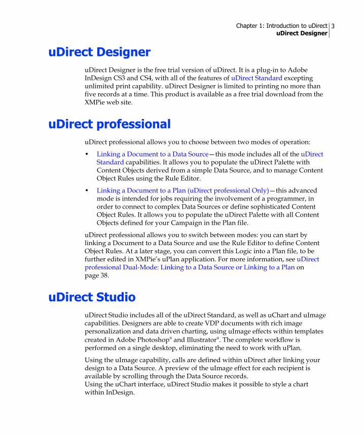
uDirect DesigneruDirect Designer is the free trial version of uDirect. It is a plug-in to Adobe InDesign CS3 and CS4, with all of the features of uDirect Standard excepting unlimited print capability. uDirect Designer is limited to printing no more than five records at a time. This product is available as a free trial download from the XMPie web site.
uDirect professionaluDirect professional allows you to choose between two modes of operation:
• Linking a Document to a Data Source—this mode includes all of the uDirect Standard capabilities. It allows you to populate the uDirect Palette with Content Objects derived from a simple Data Source, and to manage Content Object Rules using the Rule Editor.
• Linking a Document to a Plan (uDirect professional Only)—this advanced mode is intended for jobs requiring the involvement of a programmer, in order to connect to complex Data Sources or define sophisticated Content Object Rules. It allows you to populate the uDirect Palette with all Content Objects defined for your Campaign in the Plan file.
uDirect professional allows you to switch between modes: you can start by linking a Document to a Data Source and use the Rule Editor to define Content Object Rules. At a later stage, you can convert this Logic into a Plan file, to be further edited in XMPie’s uPlan application. For more information, see uDirect professional Dual-Mode: Linking to a Data Source or Linking to a Plan on page 38.
uDirect StudiouDirect Studio includes all of the uDirect Standard, as well as uChart and uImage capabilities. Designers are able to create VDP documents with rich image personalization and data driven charting, using uImage effects within templates created in Adobe Photoshop® and Illustrator®. The complete workflow is performed on a single desktop, eliminating the need to work with uPlan.
Using the uImage capability, calls are defined within uDirect after linking your design to a Data Source. A preview of the uImage effect for each recipient is available by scrolling through the Data Source records. Using the uChart interface, uDirect Studio makes it possible to style a chart within InDesign.

Chapter 1: Introduction to uDirect Installation and Upgrades from Previous Versions
4
Installation and Upgrades from Previous Versions
Hardware and Software RequirementsThe uDirect plug-in software is available for Windows or Macintosh.
Using uDirect requires Adobe InDesign CS3 or CS4. A trial version of InDesign can be downloaded from www.adobe.com.
Windows• Processor: Intel® Core™ Duo
• Operating System:Microsoft® Windows XP® with Service Pack 3OR:Microsoft Windows Vista™ 32-bit Business (or above) with Service Pack 1
Macintosh• Processor: PowerPC G4 800 MHz or better, or MacIntel 2.0 GHz
• Operating System:MAC OS X 10.4.8 OR:Mac OS X 10.5.x
General Requirements• 1 GB RAM (recommended 2 GB)
• 80 GB Hard Disk (recommended 250 GB)
• CD/DVD-ROM Drive
• 10/100/1000 Mbps Ethernet Adapter
• Adobe InDesign CS3 or CS4
Note: To install uDirect, you must have administrative privileges.

Chapter 1: Introduction to uDirect Installation and Upgrades from Previous Versions
5
• If uImage is used—Adobe Photoshop and Illustrator CS3 or CS4
Before Starting the Installation• If your InDesign desktop application has never been launched, launch it now
(and then close the application).
• If multiple versions of Adobe Creative Suite are installed on the same machine, XMPie products are installed only on the latest Adobe version. For example, if both InDesign CS3 and InDesign CS4 are installed on the same computer, the XMPie installation is performed only on InDesign CS4.It is advised to install a single version of Adobe products (either CS3 or CS4) on the machine intended to run your XMPie products.
Installing or Upgrading uDirect
1. Double-click the uDirect Installer.The installation process begins.
2. Follow the installer’s instructions.
3. After the installation ends, it is recommended to restart your computer.
4. Launch Adobe InDesign.The XMPie uDirect Palette is displayed and you can start working with uDirect.
Note: For information on Specialty Imaging system requirements, see System Requirements for Specialty Imaging Printing (VIPP Only) on page 201.
Note: It is highly recommended to install uProduce 4.6 with Adobe InDesign Server CS4. If the machine intended to run uProduce 4.6 already has InDesign CS3 installed, it is advised to uninstall CS3 before installing uProduce 4.6.
Note: If both the English and the Japanese InDesign CS3 and CS4 versions are installed on the same machine, the uDirect plug-in is added only to the English version.
Note: If the XMPie uDirect Palette does not open automatically, open it from the InDesign menu, by choosing Windows > XMPie uDirect.

Chapter 1: Introduction to uDirect Activating your uDirect License Key
6
Activating your uDirect License KeyThe first time you launch uDirect, you are asked to activate your license. This process is required only the first time uDirect is installed on a computer. Re-installations and upgrades perform the activation process automatically, without requiring any action on your part.
The activation process is simple:
• If you have a valid license key and an internet connection, the whole process is performed automatically by uDirect.
• If the machine running uDirect is not connected to the internet, you are required to perform the activation manually. In this case, the activation information is first obtained from another machine that is connected to the internet. You can then use this information, together with the license key, and to activate the product on the uDirect machine.
To activate uDirect:1. Launch InDesign.
The initial screen of the XMPie uDirect Palette is displayed (Figure 1).
2. In the Palette, click Activate Key….
Alternatively, click the button at the top of the uDirect Palette to display the Options menu and select Activate License key….
Figure 1: XMPie uDirect Palette—Prior to Product Activation
Note: The uDirect Palette is described in detail on page 14.

Chapter 1: Introduction to uDirect Activating your uDirect License Key
7
The XMPie Product Activation dialog is displayed (Figure 2).
3. In the License Key field, enter the license key you received when you purchased uDirect.
4. In the Is the network connected? section, specify if the machine running uDirect is connected to the Internet. Choose one of the following:
Connected. Use the internet to activate this product—see Activating uDirect Automatically.Not connected. Activate this product manually—see Activating uDirect Manually.
Note: If you do not have a license key, you can use a limited version of uDirect, known as uDirect Designer. To do so, click No Key… in the Palette, or select No License Key… from the Options menu (Figure 1).
Figure 2: XMPie Product Activation dialog—Activating a License Key for the First Time
Note: After activating a license key, you may use the XMPie Product Activation dialog (Figure 2) to activate additional license keys.

Chapter 1: Introduction to uDirect Activating your uDirect License Key
8
Activating uDirect AutomaticallyTo activate uDirect automatically, make sure the machine running uDirect is connected to the Internet and then follow the procedure below.
To activate uDirect automatically:1. In the XMPie Product Activation dialog (Figure 2), after choosing Connected.
Use the internet to activate this product, click Activate.If you entered a valid License Key into the XMPie Product Activation dialog, uDirect is automatically activated and a confirmation message is displayed, indicating the type of uDirect plug-in you have activated (Figure 3).
Figure 3: Activation Succeeded message (uDirect Professional)

Chapter 1: Introduction to uDirect Activating your uDirect License Key
9
Activating uDirect ManuallyIf the machine running uDirect is NOT connected to the Internet, you need to use another machine that is connected to the Internet to manually obtain the activation information (an Activation Key), as described below.
To activate uDirect manually:1. In the XMPie Product Activation dialog (Figure 2), after choosing Not
connected. Activate this product manually, click Activate.The XMPie Manual Product Activation dialog is displayed (Figure 4), indicating your Machine ID and License Key.
2. Note the Machine ID and License Key of the machine running uDirect—when you connect to the Internet from a different machine, you will be required to provide this information.
3. To obtain the Activation Key, go to a machine that is connected to the Internet and browse to http://il.xmpie.com/activation.The XMPie License Key Activation Site is displayed (Figure 5).
Figure 4: XMPie Manual Product Activation dialog
Chapter 1: Introduction to uDirect Activating your uDirect License Key
10
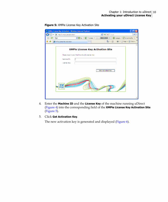
4. Enter the Machine ID and the License Key of the machine running uDirect (Figure 4) into the corresponding field of the XMPie License Key Activation Site (Figure 5).
5. Click Get Activation Key.The new activation key is generated and displayed (Figure 6).
Figure 5: XMPie License Key Activation Site

Chapter 1: Introduction to uDirect Activating your uDirect License Key
11
6. Make a note of the Activation Key.
7. Go back to the machine running uDirect, and enter the Activation Key into the corresponding filed of the XMPie Manual Product Activation dialog (Figure 4).
8. Click Activate.uDirect is activated and a confirmation message is displayed, indicating the type of uDirect plug-in you have activated (Figure 3 on page 8).
Figure 6: XMPie License Key Activation Site—New Activation Key

Chapter 1: Introduction to uDirect Activating your uDirect License Key
12
Activating an Additional License KeyAfter you first activate uDirect using an initial license key, you may add more license keys to enable additional uDirect features. For example, you may first activate a uDirect Classic license key, and then add a uChart license key.
To add a license key:1. From the uDirect Palette Options menu, choose Add License….
The Add Product License dialog is displayed (Figure 7).
2. In the License Key field, enter the license key you wish to add.
3. In the Is the network connected? section, specify if the machine running uDirect is connected to the Internet. Choose one of the following:
Connected. Use the internet to activate this product—see Activating uDirect Automatically.Not connected. Activate this product manually—see Activating uDirect Manually.
Figure 7: XMPie Product Activation dialog—Activating an Additional License Key

Chapter 2
Getting Started with uDirectThe uDirect plug-in allows you to create Dynamic Documents, by tagging static design objects (for example, a picture box, a string of text, etc.) with variables known as Content Objects. Content Objects are created automatically by uDirect when you link your InDesign document to the Campaign Logic.
This chapter explains how to get started with uDirect, by taking the following steps:
1. Open a new or existing InDesign document.
2. Display the uDirect Palette—see uDirect Palette on page 14.
3. Display the Options menu—see uDirect Palette Options menu on page 20.
4. Link your document to the Campaign Logic—see Linking a Document to your Campaign Logic on page 25.
5. Tag static design objects with Content Objects—see Tagging Design Objects with Content Objects on page 42.
The following chapters explain how to perform more advanced operations, such as manually managing Content Objects and generating the Print Output file.

Chapter 2: Getting Started with uDirect uDirect Palette
14
uDirect PaletteThe uDirect Palette is usually displayed automatically when you launch InDesign, on the right hand side of the application screen area. If the Palette does not appear, you can display it by selecting Window > XMPie uDirect from the InDesign menu.
If you do not have an InDesign document open, or if your document is not linked to Logic, the uDirect Palette shows an initial screen, providing basic instructions on how to start using the product (Figure 8).
Once you open a new or existing document, you can link it to Logic by clicking the button at the top of the uDirect Palette. The Options menu is displayed, allowing you to browse to a Data Source, a Counter or a Plan (Figure 9). These linking options are described in detail in Linking a Document to your Campaign Logic on page 25.
Figure 8: uDirect Palette — Initial Screen

Chapter 2: Getting Started with uDirect uDirect Palette
15
Once you link your document to Logic, uDirect automatically creates Content Objects and displays them in the uDirect Palette (Figure 10).
Figure 9: uDirect Palette Options menu—Linking Options
Figure 10: XMPie uDirect Palette (Linked to a Data Source)

Chapter 2: Getting Started with uDirect uDirect Palette
16
The uDirect Palette provides the following options:
• Content Object Type (View List)—the type of Content Objects that are currently listed in the Palette. By default, All Types are listed. To filter the list and focus on a specific type of Content Objects (for example, Graphic Content Objects), select the relevant type from the list. For more information, see Content Object Data Column on page 17.
• Content Objects List—lists the names and types of the Content Objects included in the Data Source, Counter or Plan file you are currently linked to. Use the View drop-down list to show All Types of Content Objects, or to filter the list to show a specific type (for example, Text, Graphic, Visibility, etc.).
• Highlight Dynamic Objects—visually indicates design objects that are tagged with Content Objects in the Document.
• Proofing Settings—used to proof your Document: set the drop-down list to a Proof Set, Content Samples or a Data Source, and link to the relevant file.
Then use the record selection field ( ) to preview the Document with actual data, by browsing through the records using the arrows, or by entering the number of a specific record you wish to preview.
The uDirect Palette also includes the following visibility icons:
When you assign Visibility Content Objects to layers and spreads, you can display or hide layers and spreads, based on your Dynamic Document Logic.
Opens the Dynamic Visibility dialog, so you can assign a Visibility Content Object to the active spread. Indicates when the active spread includes Visibility Content Objects.
Opens the Dynamic Visibility dialog, so you can assign a Visibility Content Object to the active layer.Indicates when the active layer includes Visibility Content Objects.Note: The icon will be the color of the active layer.

Chapter 2: Getting Started with uDirect uDirect Palette
17
Content Object Data ColumnBy default, the uDirect Palette displays a single column, the Content Objects List, which shows the type (icon) and name of each Content Object.
In addition, you can toggle the display of a data column, which lists the value of each Content Object for the selected recipient record.
To show the Content Object Data column:1. Right click anywhere in the Content Objects list and select Show Data Column
from the context menu (Figure 11).
Figure 11: uDirect Palette—Show Data Column option
Chapter 2: Getting Started with uDirect uDirect Palette
18
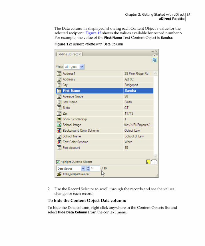
The Data column is displayed, showing each Content Object’s value for the selected recipient. Figure 12 shows the values available for record number 5. For example, the value of the First Name Text Content Object is Sandra:
2. Use the Record Selector to scroll through the records and see the values change for each record.
To hide the Content Object Data column:To hide the Data column, right click anywhere in the Content Objects list and select Hide Data Column from the context menu.
Figure 12: uDirect Palette with Data Column

Chapter 2: Getting Started with uDirect uDirect Palette
19
Content Object TypesuDirect allows you to tag design objects with different types of Content Objects.
By default, the uDirect Palette’s View drop-down displays All Types of available Content Objects. You can filter the display by choosing one of the following types from the list:
Icon Type Description
Text A text object. This string of text is shown literally in the Document. For details, see Tagging a Design Object with a Text Content Object on page 42.
Graphic A graphic object. This Content Object points to an Asset that will be shown in the Document. For details, see Tagging a Design Object with a Graphic Content Object on page 43.
Table A table consisting of column objects, whose values are extracted for each recipient from the Campaign’s Data Source(s). For details, see Tagging a Design Object with a Table Content Object on page 55.
Text file A text file containing a large amount of text or text formatted in a specific style. For details, see Tagging a Design Object with a Text File Content Object on page 43.
Visibility Controls the visibility of the InDesign document layers/spreads to which the Content Object is assigned. Visibility Content Objects also support layer names. This allows one Visibility Content Object to control the visibility of all layers, whose names match its values. For details, see Using Visibility Content Objects on page 51.
Style Applies a desired format, using one of the following types of Adobe InDesign styles:• Character Styles—when applied to text, the Style Content Object can
be used to format text attributes such as color, font, size, etc. You can also override a text style attributes with an alternative font, including the font size, font style and font color. Note: Once a Character Style Content Object is applied to text, it overrides any static InDesign style: Existing, static styles are replaced by the Style Content Object, and new styles cannot be applied on top of the Style Content Object.
• Object Styles—when applied to a frame (whether a text frame or a graphic frame), the Style Content Object can be used to format frame attributes such as fill, stroke, corner effects, etc.
Note: Each Style Content Object value must be mapped to a corresponding InDesign style, which has the exact same name.For details, see Adding or Removing a Style Content Object to or from Your Design on page 52.

Chapter 2: Getting Started with uDirect uDirect Palette Options menu
20
For detailed instructions on working with the different types of Content Objects, see Chapter 3: Managing Content Objects on page 60.
uDirect Palette Options menuClicking the icon at the top of the uDirect Palette displays the Options menu (Figure 13).
Note: Table, Visibility and Style Content Objects are incompatible with XMPie’s proprietary XLIM format. Documents containing them cannot be converted to XLIM.
Figure 13: uDirect Options menu
Chapter 2: Getting Started with uDirect uDirect Palette Options menu
21
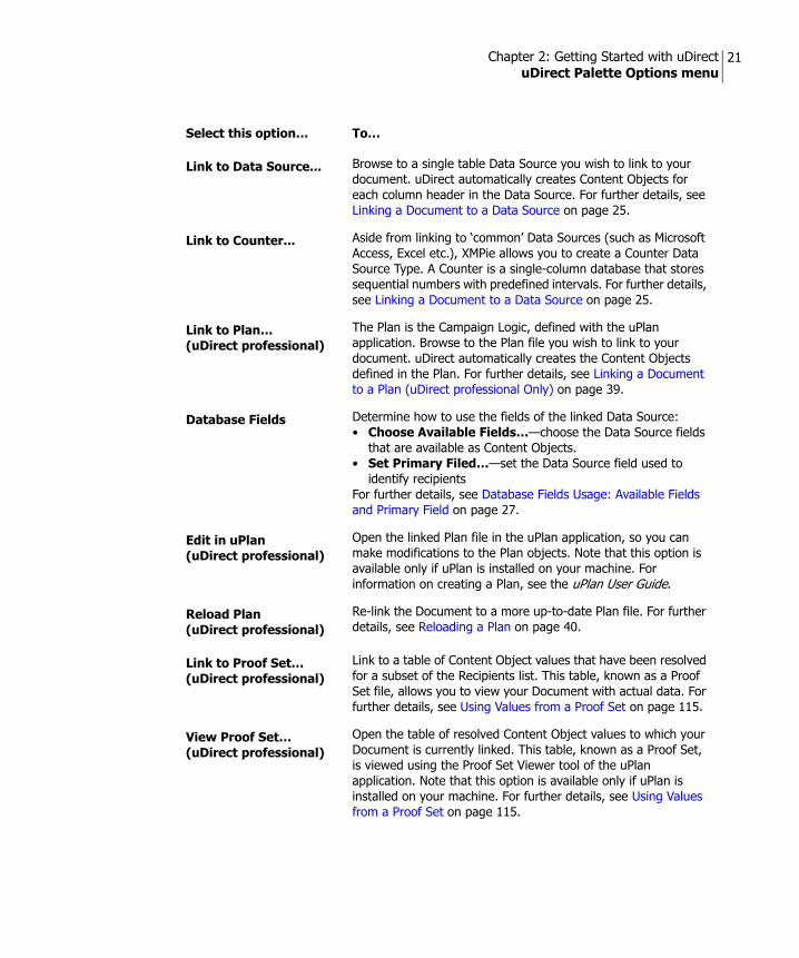
Select this option… To…
Link to Data Source... Browse to a single table Data Source you wish to link to your document. uDirect automatically creates Content Objects for each column header in the Data Source. For further details, see Linking a Document to a Data Source on page 25.
Link to Counter... Aside from linking to ‘common’ Data Sources (such as Microsoft Access, Excel etc.), XMPie allows you to create a Counter Data Source Type. A Counter is a single-column database that stores sequential numbers with predefined intervals. For further details, see Linking a Document to a Data Source on page 25.
Link to Plan…(uDirect professional)
The Plan is the Campaign Logic, defined with the uPlan application. Browse to the Plan file you wish to link to your document. uDirect automatically creates the Content Objects defined in the Plan. For further details, see Linking a Document to a Plan (uDirect professional Only) on page 39.
Database Fields Determine how to use the fields of the linked Data Source:• Choose Available Fields…—choose the Data Source fields
that are available as Content Objects.• Set Primary Filed…—set the Data Source field used to
identify recipientsFor further details, see Database Fields Usage: Available Fields and Primary Field on page 27.
Edit in uPlan (uDirect professional)
Open the linked Plan file in the uPlan application, so you can make modifications to the Plan objects. Note that this option is available only if uPlan is installed on your machine. For information on creating a Plan, see the uPlan User Guide.
Reload Plan(uDirect professional)
Re-link the Document to a more up-to-date Plan file. For further details, see Reloading a Plan on page 40.
Link to Proof Set…(uDirect professional)
Link to a table of Content Object values that have been resolved for a subset of the Recipients list. This table, known as a Proof Set file, allows you to view your Document with actual data. For further details, see Using Values from a Proof Set on page 115.
View Proof Set…(uDirect professional)
Open the table of resolved Content Object values to which your Document is currently linked. This table, known as a Proof Set, is viewed using the Proof Set Viewer tool of the uPlan application. Note that this option is available only if uPlan is installed on your machine. For further details, see Using Values from a Proof Set on page 115.

Chapter 2: Getting Started with uDirect uDirect Palette Options menu
22
Content Objects If your Design is linked to a Data Source, selecting a Content Object in the uDirect Palette allows you to manipulate it as follows:• Insert Content Object to Design—create an insertion
point in your Document and then insert this Content Object. • Rename...—override this Content Object’s name with a new
name.• Type—change this Content Object’s type. Available options
are Text, Text File, Table, Graphic, Style and Visibility.• Edit Rule...—open the Content Object Editor, where you can
edit the logical Rule that defines this Content Object.• Duplicate—create a copy of this Content Object.• Delete...—delete this Content Object.• Go to Shortest—display the record that has the shortest
value for this Text Content Object.• Go to Longest—display the record that has the longest
value for this Text Content Object.• New Content Object...—open the Content Object Editor,
where you can create a new Content Object for use in your Document.
These options are described in detail in Chapter 3: Managing Content Objects.
Convert Rules to Plan Convert the Content Object Rules to a Plan file and then continue your work using XMPie uPlan. See Converting Content Object Rules to a Plan File on page 40.
Set Assets Folder... Specify a folder that contains the Assets referenced by the Rules that assign values to Content Objects.
Set uImage Defaults… Specify the uImage default folders when using uDirect with uImage. See Setting uImage Defaults (Optional) on page 92.
Evaluate Content Objects...
View all possible literal values of a specific Text File, Graphic or Style Content Object, as defined in the Dynamic Document Logic.
Clear All Samples Delete content samples you created. For more information on using content samples, see Content Samples on page 112.
Find and Replace… Search for specified text or dynamic objects to be replaced with a dynamic object.
Evaluate Document for XLIM...
Check the document for any design item that might not be supported by the XLIM format. This feature provides information on such issues, and explains how the software will handle them.
Select this option… To…
Chapter 2: Getting Started with uDirect uDirect Palette Options menu
23
XLIM Design Mode Enter a mode in which every time a page item is selected, the previously selected page item is checked for XLIM compatibility, and if a problem is identified, it is immediately reported.
Preview XLIM Document...
Create a XLIM version of the document and immediately displays it as an Untitled InDesign document.It is also possible to generate a PDF-rendering of the XLIM document on the desktop (Windows only). This is particularly useful for preview purposes, before exporting the XLIM package to uProduce.
XMPie Exchange Export...
Create a package file that can be uploaded to a uProduce server, where it can become part of a cross-media Campaign, drive the Campaign from a more sophisticated database, or simply allow your print service provider to make last minute changes and production-related design or data adjustments.For further details on creating Campaign packages (*.cpkg) and Document packages (*.dpkg), see Using XMPie Exchange Packages on page 120.
XMPie Exchange Import...
Import a document from an existing package file. This feature is useful for collaboration between uDirect users who do not share a Data Source, or as a download for design collaboration with print service providers. For further details on importing Document packages, see Using XMPie Exchange Packages on page 120.
Export Proof Set... Create a Proof Set file. Other uDirect users can use such files to see previews of their designs with sample data used to create this Proof Set.
Clear Global Cache… (VPS & PPML output formats)
Notifies the RIP to clear cached elements of similar runs that are stored on the RIP. Clear the global cache to improve the RIP processing performance between runs of the same document. For more information, refer to Use Global Caching on page 135.
Preflight... Check the document for any design item that might cause performance issues during the production run when using transparency or contour wrapping techniques. Transparency techniques include drop shadow, feathering, opacity that is lower than 100% and transparent images. Contour wrapping refers to text that is wrapped around an object shape (that is, shape contour) either from one side or two sides of the object.The tool provides information on techniques that affect production performance (that is, transparency and contour wrapping) and explains how the software will handle them. Furthermore, the design objects that relate to the problem are selected and displayed in the design for reference.
Select this option… To…

Chapter 2: Getting Started with uDirect uDirect Palette Options menu
24
Dynamic Print... Create a Print Output file from the InDesign Dynamic Document using values from the source currently being used to drive the document's Content Objects. This source may be one of the following at any given time: Data Source, Proof Set, or content samples. For further details on creating print files, Chapter 6: Printing the Dynamic Document on page 128.
Help Open the uDirectUser Guide.
uImage User Guide… Open the uImage User Guide.
No License Key… Allows you to use a limited version of uDirect, known as uDirect Designer (see uDirect Designer on page 3).
Add License… Add a license by opening the Add Product License dialog and entering your license key. Note that you may add new licenses in addition to exiting licenses. For example, you may start with a uDirect Classic license and then add a uChart license.
Activate License Key… Open the XMPie Product Activation dialog and activate your license key (see Activating your uDirect License Key on page 6).
About XMPie uDirectStandard/professional…
Display information on the current version of uDirect Standard/professional.
Select this option… To…

Chapter 2: Getting Started with uDirect Linking a Document to your Campaign Logic
25
Linking a Document to your Campaign LogicContent Objects are defined based on a number of attributes; their name, their type, and their business rule (Rule, in short). A Rule is an expression that defines how to calculate the Content Object’s value for each recipient. Rules are part of the Campaign Logic defined in the Campaign’s Plan file, but they can also be added or edited using uDirect’s Rule Editor.
You can easily obtain your Campaign’s Content Objects, by linking your Document to the Logic. The linking operation may be performed at any stage of the design process, as long as you have an InDesign document open. Once the Document is linked to Logic, uDirect automatically creates the Content Objects and displays them in the uDirect Palette.
The linking operation is performed in one of the following ways:
• Linking a Document to a Plan (uDirect professional Only) on page 39—uDirect creates the Content Objects defined in the Plan file. Use this option for jobs requiring the involvement of a programmer, in order to connect to complex Data Sources or define sophisticated Content Object Rules.
• Linking a Document to a Data Source (see below) —uDirect creates a Content Object for each column header in the linked Data Source. Use this option if you have a simple Data Source (such as an Excel file containing name and address information), and wish to use straightforward Content Object Rules.
Linking a Document to a Data SourceWhen you link your Document to a Data Source, uDirect automatically creates a Content Object for each column header in that Data Source. You may use these Content Objects as they are, or manage them to suit your specific needs (see Chapter 3: Managing Content Objects).
Supported Data Sources The mode allows you to link directly to any of the following Data Sources:
Windows
• Text Files (*.txt)
• Comma Separated Values (*.csv)
• Microsoft Excel (*.xls)
• Microsoft Access (*.mdb)
• dBase (*.dbf)

Chapter 2: Getting Started with uDirect Linking a Document to your Campaign Logic
26
Macintosh
• Text Files (*.txt)
• Comma Separated Values (*.csv)
To link a document to a Data Source:
1. From the uDirect Options menu, select the Link to Data Source... option. The Select a Data Source dialog is displayed.
2. Browse to the Data Source file and click Open.
3. Specify Data Source-specific settings:If you selected a delimited text file, the Specify a Separator dialog is displayed. Select the appropriate delimiter used to separate data values in your text file and click OK.If you select a Data Source with more than one table, the Choose a Table dialog is displayed. Select the table you wish to use for creating Content Objects and click OK.
When you link the Document to a Data Source for the first time, uDirect automatically creates a Content Object for each column header in the Data Source. These Content Objects are displayed in the uDirect Palette. By default, the type of all new Content Objects is Text.
To filter the list of Content Objects by type, select one of the following options from the View drop-down list:
• All Types
• Text
• Graphic
• Table
• Text File
• Visibility
• Style
Note: When you link your Document to a Data Source, certain types of data files (such as FileMaker *.csv files) do not export the column headers, causing the Content Objects to appear as the data in the first record. To include the column headers in the data file, open the file in another program (such as Notepad or Microsoft Excel on Windows, or such as TextEdit on Mac OS), and add the column headers manually.

Chapter 2: Getting Started with uDirect Linking a Document to your Campaign Logic
27
Database Fields Usage: Available Fields and Primary Field
uDirect reflects the Data Source structure, by making all fields (column headers) available as Content Objects. You can change the way a Data Source is used in a specific Document, by Choosing the Available Data Source Fields and Setting the Primary Field.
Choosing the Available Data Source FieldsuDirect automatically creates a Content Object for each field in the linked Data Source. However, if your Document does not require some these fields, you may prefer to remove them from the Palette.
To choose the available Data Source fields:1. From the Options menu, select Database Fields > Choose Available Fields...
The Select a Data Source dialog is displayed (Figure 14).
2. Go over the list and make sure only fields that are used in this Document are selected. To revert to the default setting, which includes all fields, click Select All.
3. Click OK to save your settings and close the dialog.
Figure 14: Choose Available Fields dialog

Chapter 2: Getting Started with uDirect Linking a Document to your Campaign Logic
28
Setting the Primary FieldSimilarly, uDirect uses the Data Source definition of a Primary field, that is: the column header that uniquely identifies each recipient, such as a social security number; passport number; driver’s license number; email, etc. However, for a specific Document, you may prefer to use a different primary field.
To set the Data Source’s Primary field:1. From the Options menu, select Database Fields > Set Primary Field...
The Set Primary Field dialog is displayed (Figure 15).
2. From the Primary Field drop-down list, select the field you wish to use as the unique identifier of recipients.
3. Click OK to save your settings and close the dialog.
Counter Data SourcesAside from linking to ‘common’ Data Sources (such as MS Access, etc.), uDirect provides you with the option to create a Counter Data Source single-column database that stores sequential numbers with predefined intervals.
A Counter Data Source is very useful if you need to create a Document in which the only dynamic components are numbers, for example: lottery tickets, coupons, receipts, vouchers, etc. The Counter Data Source provides a convenient tool for generating such numbers, without a need to prepare them in a separate Data Source.
Note: If you have mistakenly deselected fields that are currently linked in your Document, uDirect displays a warning, allowing you to match these fields to any of the chosen fields. For details on matching different Data Sources, see Re-Linking a Document to an Updated or Different Data Source on page 30.
Figure 15: Set Primary Field dialog

Chapter 2: Getting Started with uDirect Linking a Document to your Campaign Logic
29
Content Object List Context Menu
If your Design is linked to a Data Source, right-clicking anywhere in the Content Object list of the uDirect Palette displays the following context menu (Figure 16):
This context menu allows you to conveniently access the same operations available by going to the Options menu and choosing Content Objects:
Note: This option is available only if you are linked to a Data Source or a Counter (and not to a Plan file).
Figure 16: Content Object List Context Menu
Select this option… To…
Insert to Design Create an insertion point in your Document and then insert this Content Object.
Rename… Override this Content Object’s name with a new name.
Type Change this Content Object’s type. Available options are Text, Text File, Table, Graphic, Style and Visibility.
Edit Rule Open the Content Object Editor, where you can edit the logical Rule that defines this Content Object.
Duplicate Create a copy of this Content Object.
Delete Delete this Content Object.
Go to Shortest Display the record that has the shortest value for this Text Content Object.
Go to Longest Display the record that has the longest value for this Text Content Object.
Show Data Column Display the uDirect Palette’s Data column, which lists the value of each Content Object for the selected recipient record.

Chapter 2: Getting Started with uDirect Linking a Document to your Campaign Logic
30
These options are described in detail in Chapter 3: Managing Content Objects.
Re-Linking a Document to an Updated or Different Data Source
After you link your Document to a Data Source and start working, you may wish to use the Document with a new set of data. In other cases, the Data Source the Document is linked to may change.
The structure of the previous Data Source—columns, field names, and so forth—may be different from the structure of the current Data Source. For example, your first Data Source may contain the fields “First Name”, “Last Name”, and “Occupation”. You may later link to a different Data Source, containing the fields “FName”, “LName”, “profession”, and “country”.
Whether you initiated the link to a different Data Source, or are responding to changes in the linked Data Source, re-linking your Document to data requires matching the previous and current Data Sources.
Matching the Previous and Current Data SourcesWhen uDirect detects changes in the Data Source linked to your Document, it launches the Link to Data Source wizard. This wizard helps you match each field of the previous Data Source with a field in the current Data Source.
The following sections explain how to perform Data Source Matching Triggered by Changes in the Document and Data Source Matching Triggered by Changes in the Data Source.
Hide Data Column Hide the uDirect Palette’s Data column, which lists the value of each Content Object for the selected recipient record.
New Content Object
Open the Content Object Editor, where you can create a new Content Object for use in your Document.
Select this option… To…
Insert to Design Create an insertion point in your Document and then insert this Content Object.
Note: Fields that are used in your Document (that is: fields of the previous Data Source that are used as Content Objects) MUST be handled: either match them with fields of the current Data Source, or convert them to static text.
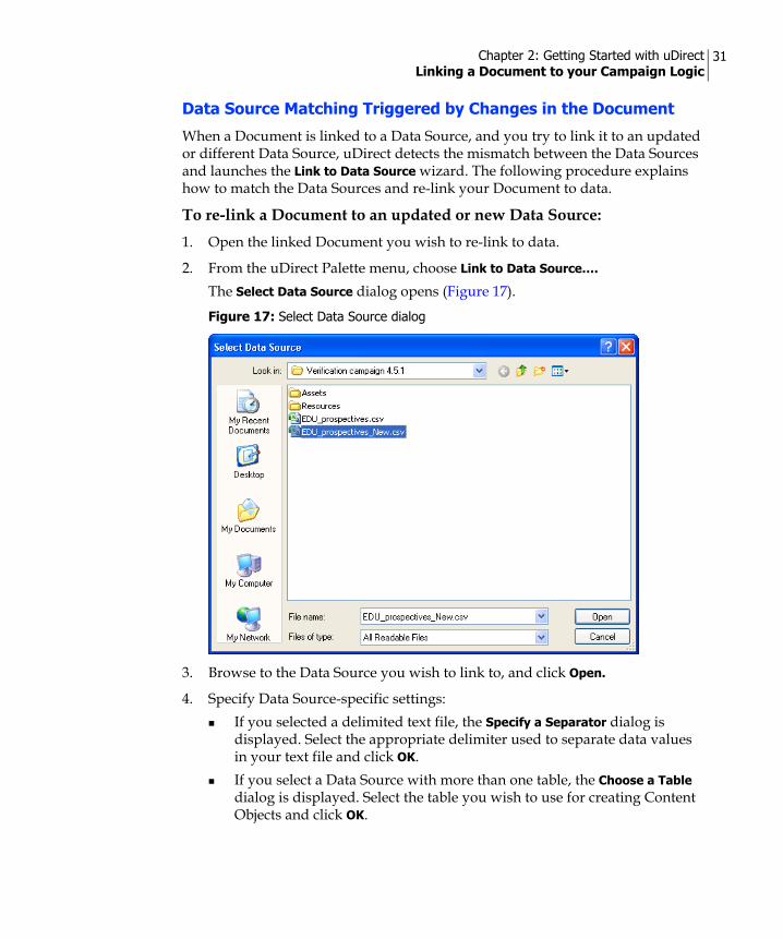
Chapter 2: Getting Started with uDirect Linking a Document to your Campaign Logic
31
Data Source Matching Triggered by Changes in the Document
When a Document is linked to a Data Source, and you try to link it to an updated or different Data Source, uDirect detects the mismatch between the Data Sources and launches the Link to Data Source wizard. The following procedure explains how to match the Data Sources and re-link your Document to data.
To re-link a Document to an updated or new Data Source:1. Open the linked Document you wish to re-link to data.
2. From the uDirect Palette menu, choose Link to Data Source….
The Select Data Source dialog opens (Figure 17).
3. Browse to the Data Source you wish to link to, and click Open.
4. Specify Data Source-specific settings:If you selected a delimited text file, the Specify a Separator dialog is displayed. Select the appropriate delimiter used to separate data values in your text file and click OK.If you select a Data Source with more than one table, the Choose a Table dialog is displayed. Select the table you wish to use for creating Content Objects and click OK.
Figure 17: Select Data Source dialog

Chapter 2: Getting Started with uDirect Linking a Document to your Campaign Logic
32
If there are any mismatches between the previous and current Data Sources, the Link to Data Source: Match Previous and Current Data Sources wizard is displayed (Figure 18).
5. To successfully link to the current Data Source, each Previous Data Source Field that is used in your Document as a Content Object must be handled:
Match it with a field of the current Data Source ORConvert it to static text
Specify how to perform the matching using the following options:
Figure 18: Link to Data Source: Match Previous and Current Data Sources wizard
Option Description
Previous Data Source Field
Lists all fields (column headers) in the previous Data Source, which were used to create Content Objects. All these fields must be matched or converted to static text.
Action or Current Data Source Field
Determines how to handle the fields of the previous Data Source. Each field has a drop-down list, allowing you to choose an action to be performed or a matching field of the current Data Source. The available actions and fields are described below.

Chapter 2: Getting Started with uDirect Linking a Document to your Campaign Logic
33
<<Unmatched>> A field of the previous Data Source that is unmatched by a field of the current Data Source. Tip: When a field is unmatched, its Content Object’s expression becomes invalid. To re-link the Document successfully, you must match all fields or replace them with static text.
<<Replace with Static Text…>>
Choose this option if a field in the previous Data Source does not exist in the current Data Source, to ensure all Content Object Rules remain valid. This option displays a Text box (Figure 19), allowing you to enter static text. This text will replace all instances in which this field’s Content Object appears in your Document, Note: leaving the text box empty and clicking Next invokes an error message.
Figure 19: Link to Data Source—<<Replace with Static Text…>> option
Fields For each field of the previous Data Source, choose the matching field of the current Data Source. Note the following (Figure 20 on page 34):• Fields that have the same name in both Data Sources (such as
City, First Name etc.) are automatically matched. • Matching fields are grayed out in the drop-down lists of other
fields (in our example, First Name is grayed out the City drop-down lists).
• When a matching field is found, it can only be replaced by one of the unmatched fields (or by an action). For example, the City drop-down offers the matching field City, as well as the unmatched fields Add_1, Add_2 and RID.
Option Description
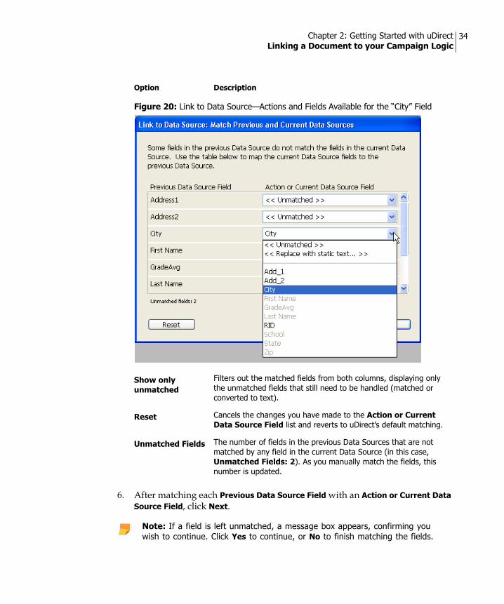
Chapter 2: Getting Started with uDirect Linking a Document to your Campaign Logic
34
6. After matching each Previous Data Source Field with an Action or Current Data Source Field, click Next.
Figure 20: Link to Data Source—Actions and Fields Available for the “City” Field
Show only unmatched
Filters out the matched fields from both columns, displaying only the unmatched fields that still need to be handled (matched or converted to text).
Reset Cancels the changes you have made to the Action or Current Data Source Field list and reverts to uDirect’s default matching.
Unmatched Fields The number of fields in the previous Data Sources that are not matched by any field in the current Data Source (in this case, Unmatched Fields: 2). As you manually match the fields, this number is updated.
Note: If a field is left unmatched, a message box appears, confirming you wish to continue. Click Yes to continue, or No to finish matching the fields.
Option Description

Chapter 2: Getting Started with uDirect Linking a Document to your Campaign Logic
35
7. Create new Content Objects for new fields in the current Data Source (optional):If the current Data Source includes new fields that did not exist in the previous Data Source, the Create new Content Objects dialog is displayed. A new field may either be an additional field that did not exist in the previous Data Source, or an unmatched field that has a different name (Figure 21).
8. Specify whether to create a new Content Objects for each new field:In the Create? column, check the box of each new Current Data Source Field for which you wish to create a new Content Object.To create new Content Objects for all new fields, click Select All.To refrain from creating new Content Objects, click Select None.
9. Determine how to proceed:If you need to change the field matching (specifically, handle any remaining unmatched fields), click Prev to return to the Link to Data Source: Match Previous and Current Data Sources wizard (Figure 18).To abort the whole operation and keep the Document linked to the previous Data Source, click Cancel.
Figure 21: Create New Content Objects dialog
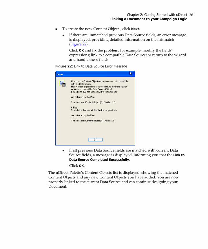
Chapter 2: Getting Started with uDirect Linking a Document to your Campaign Logic
36
To create the new Content Objects, click Next.If there are unmatched previous Data Source fields, an error message is displayed, providing detailed information on the mismatch (Figure 22). Click OK and fix the problem, for example: modify the fields’ expressions; link to a compatible Data Source; or return to the wizard and handle these fields.
If all previous Data Source fields are matched with current Data Source fields, a message is displayed, informing you that the Link to Data Source Completed Successfully. Click OK.
The uDirect Palette’s Content Objects list is displayed, showing the matched Content Objects and any new Content Objects you have added. You are now properly linked to the current Data Source and can continue designing your Document.
Figure 22: Link to Data Source Error message
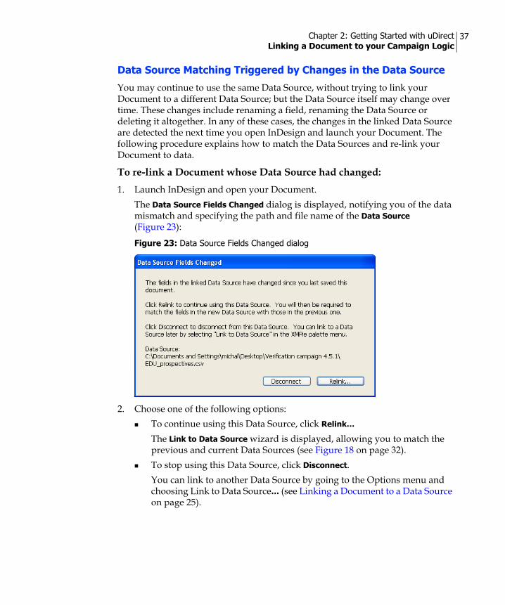
Chapter 2: Getting Started with uDirect Linking a Document to your Campaign Logic
37
Data Source Matching Triggered by Changes in the Data Source
You may continue to use the same Data Source, without trying to link your Document to a different Data Source; but the Data Source itself may change over time. These changes include renaming a field, renaming the Data Source or deleting it altogether. In any of these cases, the changes in the linked Data Source are detected the next time you open InDesign and launch your Document. The following procedure explains how to match the Data Sources and re-link your Document to data.
To re-link a Document whose Data Source had changed:1. Launch InDesign and open your Document.
The Data Source Fields Changed dialog is displayed, notifying you of the data mismatch and specifying the path and file name of the Data Source (Figure 23):
2. Choose one of the following options: To continue using this Data Source, click Relink…
The Link to Data Source wizard is displayed, allowing you to match the previous and current Data Sources (see Figure 18 on page 32). To stop using this Data Source, click Disconnect.You can link to another Data Source by going to the Options menu and choosing Link to Data Source… (see Linking a Document to a Data Source on page 25).
Figure 23: Data Source Fields Changed dialog

Chapter 2: Getting Started with uDirect Linking a Document to your Campaign Logic
38
uDirect professional Dual-Mode: Linking to a Data Source or Linking to a Plan
uDirect professional allows you to choose between two modes:
• Linking a Document to a Data Source (see page 25)—this mode is available to all uDirect users. The linking operation automatically populates the uDirect Palette with Content Objects derived from the selected Data Source, and allows you to manage Content Objects Rules using uDirect’s Rule Editor.
• Linking a Document to a Plan (uDirect professional Only) (see page 39)—this mode is available only to uDirect professional users. The linking operation automatically populates the uDirect Palette with Content Objects defined by the Campaign’s Plan file. Note that these Content Objects are cannot be managed using the Rule Editor. Instead, they are managed as part of the Plan file, using the uPlan application.
uDirect professional’s mode is set per-Document, and determines which Palette and menu options are available:
• When you open a Static Document, both modes are available: the Options menu allows you to choose between linking to a Data Source (including a Counter Data Source) and linking to a Plan.
• When you open a Document that is already linked to Logic, the uDirect Palette and Options menu enable the relevant settings and disable others. For example:
• If the Document is linked to a Data Source, you have different options for managing Content Objects.
• If the Document is linked to a Plan, you cannot manage Content Objects, but have other options, such as reloading the Plan or using Proof Sets.
Both modes support the same point-and-click operations for tagging design objects with the desired Content Objects.
Switching ModesuDirect professional allows you to work with both Data Sources and Plan files, using either the Rule Editor or uPlan (respectively) to design your Campaign Logic.
If you initially chose to work with a Data Source, and designed your Document Logic using the Rule Editor, you can convert all Rules to a Plan file (see Converting Content Object Rules to a Plan File on page 40) and continue your work using XMPie uPlan.
Chapter 2: Getting Started with uDirect Linking a Document to your Campaign Logic
39
Note that this change is irreversible: once you convert your Content Object Rules to a Plan file, you can no longer edit them using a Rule Editor. Instead, the Plan file you created can be managed using the uPlan application.
Linking a Document to a Plan (uDirect professional Only)
To obtain the Content Objects defined in your Campaign Logic, you must first link your Document to a Plan file. The Plan represents the Campaign’s Logic component and is defined with the uPlan application. For information on creating a Plan, refer to the uPlan User's Guide.
Supported Data SourcesBy linking to a Plan file (instead of linking directly to a Data Source), uDirect professional allows you to work with both simple and complex ODBC-compliant Data Sources, including Text, CSV, Microsoft Excel, Microsoft Access, FoxPro, DBF, SQL Server and Oracle.
To link a document to a Plan:1. From the Options menu, select Link to Plan…. Alternatively, you can click
the Plan icon. The Select a Plan File dialog is displayed.
2. Browse to the Plan file and click Open.
The uDirect Palette automatically lists all Content Objects in the Plan file. The name of the Plan file is displayed at the top of the Palette. The tool tip for the Plan file name shows you the full path of the Plan file and its modification date.
Editing a PlanWhen a Plan is linked to a document, you can open and edit the Plan in the uPlan application while you are working with InDesign. This option is only available if you have the uPlan module installed on your computer.
To edit a Plan:1. From the Options menu, select Edit in uPlan.
The uPlan application opens and displays the linked Plan.
2. Edit the Plan and save the changes.
3. Close uPlan and return to InDesign. A message is displayed, prompting you to reload the Plan file.
4. Click Yes to reload the Plan.

Chapter 2: Getting Started with uDirect Linking a Document to your Campaign Logic
40
If any of the changes you made to the Plan affect the Content Objects currently used in your Document, the Plan will no longer be compatible with your Document. A dialog will appear, describing the cause of the incompatibility.
5. Choose one of the following:Ignore—ignores the inconsistencies and allows you to continue working with the currently linked Plan.OR:Cancel —cancels reloading.
If you use a Plan that is incompatible with the Dynamic Document, it will result in unsuccessful print production. If you choose Ignore, this message will reappear the next time you open the Document (after saving). To avoid this message, edit the Document to accommodate the changes described in the message, or update the Plan to reflect the current design.
Reloading a PlanThe Reload Plan… option allows you to re-link the current document to the currently linked Plan file. If changes were made to the Plan and as a result, the Plan and the design are incompatible, a message is displayed informing you of the incompatibilities.
This option is useful if you are currently working on a Document that is linked to a specific Plan and the Plan is modified. Reloading the Plan will ensure that you are working with the most up-to-date copy of the Plan.
Converting Content Object Rules to a Plan File
uDirect professional allows you to work with Plan files as well as Data Sources, thus allowing you to choose between the Rule Editor and uPlan depending on what is most suitable for designing your Campaign Logic.
If you initially chose to define your Campaign Logic using the Rule Editor, you can convert the Content Object Rules to a Plan file and then continue your work using XMPie uPlan.
Note that once your Content Object Rules have been converted to a Plan file, you can only use uPlan to edit them. You will not be able to revert to editing these Rules using the Rule Editor.
Note: This option is available only if you are linked to a Data Source or a Counter (and not to a Plan file).

Chapter 2: Getting Started with uDirect Linking a Document to your Campaign Logic
41
To convert your Content Object Rules to a Plan file:1. From the Options menu, select Convert to Plan.
You are prompted to confirm that you wish to convert your Content Object Rules to a Plan file.
2. Click Yes to confirm the Plan conversion.The Save Plan As dialog is displayed.
3. Browse to the location where you want to save the Plan file, enter a name for the Plan file and then click Save.
Figure 24: Convert to Plan File Confirmation Message
Figure 25: Save Plan As dialog
Note: By default, the newly created Plan file name is set to the name of your Document.

Chapter 2: Getting Started with uDirect Tagging Design Objects with Content Objects
42
Tagging Design Objects with Content ObjectsYou can create Dynamic Objects by tagging a Design Object with a Content Object. For example, creating a static graphic frame and tagging it with a Graphic Content Object results in a dynamic graphic frame.
To create a Dynamic Object in your design you select a design object and double-click a Content Object in the Content Objects list. This will associate this Content Object with the selected design object.
You can deselect or select the Highlight Dynamic Objects option to highlight dynamic design objects in your document. When this option is selected, your document will display the name of the Content Object associated with each dynamic design object.
Tagging a Design Object with a Text Content ObjectTo tag a design object with a Text Content Object:1. Click the Type Tool icon and then use the mouse to draw a rectangular area in
the document. Alternatively, you can make a text selection, or use the text insertion point, in an existing text box in the document.
2. In the uDirect Palette, double-click the desired Text Content Object, or select the desired Text Content Object and then select Insert to Design from the context menu. The object is inserted into your document.
You can now proceed to format the text using standard InDesign methods.
For details on how to modify the Text Content Object’s properties, see Dynamic Text Properties on page 98.

Chapter 2: Getting Started with uDirect Tagging Design Objects with Content Objects
43
Tagging a Design Object with a Graphic Content Object
The Graphic Content Object is a pointer to a graphic file that is used in your Dynamic Document.
To insert a Graphic Content Object:• In the uDirect Palette, double-click the desired Graphic Content Object, or
select the desired Graphic Content Object and then select Insert to Design from the context menu. The object is inserted into your document. If there is a rectangle selected in InDesign, the Graphic Content Object will be inserted to it; otherwise, a new rectangle will be created for the Content Object.
• You can also make a text selection in InDesign, and insert the Graphic Content Object as an inline image.
You can now proceed to modify the graphic using standard InDesign methods.
For details on how to modify the object’s properties, see Dynamic Graphic Properties on page 103.
Tagging a Design Object with a Text File Content Object
The Text File Content Object is a pointer to a text file that is referred to in your Data Source.
To insert a Text File Content Object:1. Click the Type Tool icon and then use the mouse to draw a rectangular area in
the document. Alternatively, you can make a text selection, or use the text insertion point, in an existing text box in the document.
2. In the uDirect Palette, double-click the desired Text File Content Object, or select the desired Text File Content Object and then select Insert to Design from the context menu. The object is inserted into your document.
Note: You can check the literal values defined for this Graphic Content Object in the Dynamic Document Logic, by displaying the uDirect Options menu and choosing Evaluate Content Objects. For more information, see uDirect Palette Options menu on page 20.
Note: You can check the literal values defined for this Text File Content Object in the Dynamic Document Logic, by displaying the uDirect Options menu and choosing Evaluate Content Objects. For more information see uDirect Palette Options menu on page 20.

Chapter 2: Getting Started with uDirect Tagging Design Objects with Content Objects
44
Using Nested CompositionText File Content Objects are used to create dynamic text by referencing recipient-specific text files stored in the Assets folder. Many times these are static text files; however, it is possible to make these Assets dynamic, by tagging the text within the file with Content Objects. By creating a Text File Content Object that references two or more text files, text within your document can change dynamically depending on the conditions you have built into the Text File Content Object’s rule. This enables the values of Content Objects within each Asset to be calculated per-recipient at proofing or composition time. Accordingly, this feature is known as Nested Composition. Nested Composition is where an Asset file referenced by a Text File Content Object contains references to other Content Objects.
Nested Composition applies to the following text formats supported by Text File Content Objects:
• Plain Text (*.txt)
• Adobe Tagged Text (*.txt)
• Rich Text Files (*.rtf)
• XNIP (*.xnip) (see XNIP (*.xnip) File Format on page 124).
Tagging an Asset File with Content Object Reference Tagging an Asset with a Content Object is done by typing a Content Object's name inside double curly brackets. Below is an example of a tagged plain text Asset:
Happy birthday {{First Name}}!
The same Content Object reference method can be used in Adobe Tagged Text files (see Using Nested Composition with Adobe Tagged Text on page 47) and Rich Text files. When XNIP files are exported, Content Object tags within the exported text are embedded as part of the XNIP file.
Setting up Nested Composition with a Plain Text AssetThe example below shows the use of Nested Composition with two plain text files tagged with Content Objects. You can try the workflow described below with the uDirect Tutorial sample document (the Happy Birthday postcard).

Chapter 2: Getting Started with uDirect Tagging Design Objects with Content Objects
45
To set up nested composition with a Plain Text Asset:1. Open your text editor and create two or more text files.
2. In each file, type the text to be placed dynamically in the document, including a reference to one or more Content Objects, for example:Text File 1: {{First Name}}, as a Stellar club member, you are entitled to 50% discount.Text File 2: Had you been a club member, {{First Name}}, you would have received a discount.
3. Save each text file in the Assets folder of your Campaign, for example:Text File 1 saved as discount.txtText File 2 saved as nodiscount.txt
4. Create a new Content Object and set its type to Text File Content Object.
5. Use the If/Then Rule, and set the condition as Club level, function = String: Stellar; Then Text File = String discount; Else Text File = String nodiscount, or use the names of the Text files you saved in the Assets folder if you used different names (Figure 26).
Note: Make sure you do not type the file extension “.txt”.
Figure 26: Nested Composition—New Content Object

Chapter 2: Getting Started with uDirect Tagging Design Objects with Content Objects
46
6. In the document window, draw a text frame and tag it with the Text File Content Object (Figure 27).
7. Using the Type Tool from the InDesign tool bar, select all the text, and right-click to select Dynamic Text Properties… from the context menu.The Dynamic Text Properties dialog is displayed (Figure 28).
8. Select the Enable Nested Composition check box and click OK to save your changes.
9. Scroll through the records to view the text change dynamically within the InDesign document (Figure 29) and (Figure 30).
Figure 27: Tagged Text Content Object
Figure 28: Dynamic Text Properties—Nested Composition
Figure 29: Text File 1

Chapter 2: Getting Started with uDirect Tagging Design Objects with Content Objects
47
Using Nested Composition with Adobe Tagged TextNested Composition with Adobe Tagged Text differs from a plain text file tagged with Content Objects, in that it provides the ability for styling parts of the text in the Asset, for example setting its color, font family or point size.
To use nested composition with Adobe Tagged Text you must first create Adobe Tagged Text files.
To create a tagged Text File:1. In the InDesign document, draw a text frame and enter the text, including the
Text Content Object you wish to style, for example, {{First Name}}, as a Stellar club member, you are entitled to 50% discount.
2. Style the text as required (Figure 31).
3. Select all the text and from the File menu, select Export to export the text as an Adobe InDesign Tagged Text file (*.txt) into the Campaign's Assets folder (Figure 32).
Figure 30: Text File 2
Note: Make sure to store your Assets in the Assets folder of your Campaign.
Note: Tagged Text in this context does not relate to tagging with Content Object, but rather to Adobe proprietary tags that save style information in a text file.
Note: Make sure that if you style references to Content Objects, the whole reference, including the curly brackets, uses the same style.
Figure 31: Styled Text Content Object

Chapter 2: Getting Started with uDirect Tagging Design Objects with Content Objects
48
4. Name the text file, and click Save.The Adobe InDesign Tagged Text Export Options dialog is displayed (Figure 33).
5. Select Tag Form: Verbose, and Encoding: Unicode and click OK.
Figure 32: Export Adobe InDesign Tagged Text File
Figure 33: Adobe InDesign Tagged Text Export Options

Chapter 2: Getting Started with uDirect Tagging Design Objects with Content Objects
49
6. Repeat steps 1 to 5 for each tagged Text File, using the filenames “discounstyled” and “nodiscountstyled” if you are using the same sample detailed Setting up Nested Composition with a Plain Text Asset on page 44, or using the names of the Text files you saved in the Assets folder if you used different names.
7. Create a new Content Object as a Text File Content Object, using the If/Then Rule, condition as Club level, function = String: Stellar; Then Text File = String discountstyled; Else Text File = String nodiscountstyled, or use the names of the Text files you saved in the Assets folder if you used different names (Figure 34).
8. Using the Type Tool from the InDesign tool bar, select all the text, and right-click to select Dynamic Text Properties… from the context menu.The Dynamic Text Properties dialog is displayed (Figure 28).
9. Select the Enable Nested Composition check box and click OK to save your changes.
10. Scroll through the records to view the text and styling change dynamically within the InDesign document (Figure 35 and Figure 36).
Note: Make sure you do not type the file extension “.txt”.
Figure 34: Styled Nested Composition—New Content Object

Chapter 2: Getting Started with uDirect Tagging Design Objects with Content Objects
50
Creating Dynamic Table of Contents and IndexDynamic Text Objects (of the appropriate paragraph styles) are included in InDesign's automatically-generated Table of Contents and Index. A dynamic Table of Contents is automatically updated with each record change.
To create a dynamic index:1. In the document window, select the text you want to index. You can create a
temporary text box for the purpose of creating the index. Make sure to delete this text box when completing your index.
2. Use InDesign Index Palette to create an index entry. An index marker using the default settings is added at the beginning of the selection.
3. Select the text you have indexed and export it, using InDesign Export option, to an Adobe InDesign Tagged Text file (*.txt). Save the exported text file in the Campaign's default Assets folder. When exporting, make sure to:
Include the text you have indexed with the appropriate index marker. It is advisable to show hidden characters in the design window (use Alt+Ctrl+I).Use Unicode encoding method.
4. Delete the index marker.
5. Repeat steps 1-4 for each index entry you want to generate.
6. Create a new Content Object (or set an existing Content Object if you chose to use it as the basis for an index reference) as a Text File Content Object, which will be populated with the files you have created.
Figure 35: Styled Tagged Text File—discount
Figure 36: Styled Tagged Text File—no discount

Chapter 2: Getting Started with uDirect Tagging Design Objects with Content Objects
51
Using Visibility Content ObjectsWhen you assign a visibility object to a layer or spread in your design application, you can control whether the layer or spread will be visible or hidden. For example, if you have a personal message that is appropriate only for male recipients, you can create a Visibility Content Object called ‘ismale’. You can then select the layer that includes the message and assign the ismale Content Object to this layer or spread.
Visibility Content Objects also support layer names. This allows one Visibility Content Object to control the visibility of all layers, whose names match its values. For example, if the value of the Visibility Content Object for a given recipient is “Family”, then the layer named “Family” will be shown.
When creating a Visibility Content Object, you should take into consideration that:
• Visibility Content Object values are case sensitive, meaning a value must match the case of the layer’s name, to which it refers. If no value matches any layer's name, all layers will be turned off.
• White spaces in layer names are also supported. For example, the Visibility Content Object value "--Family--" matches the layer "--Family--" (where the character "-" indicates a white space).
• Do not name the design layers with any of the following: "0", "1", "true" or "false". These values are reserved to the Visibility Content Objects interpreter.
• Layers that are tagged as non-printable layers in Adobe InDesign are not visible when printing the design regardless of the Visibility Content Object status (visible or not visible).
To assign a Visibility Content Object to the active layer or spread:1. In your document, select the object that is part of the desired layer or spread
for which you want to control visibility.
2. Click on a Visibility Content Object and then click on the visibility icon
(either layer or spread). The Dynamic Visibility dialog opens. You are prompted to assign the Visibility Content Object to the selected layer or spread.
3. Click Assign. You can see how the visibility feature affects objects in the document by cycling through Data Source or Proof Set data.
The InDesign Layers Palette lets you toggle the visibility of layers or spreads that have visible Content Objects assigned to them. You can also access the Layers Palette by opening the Window menu and selecting Layers.
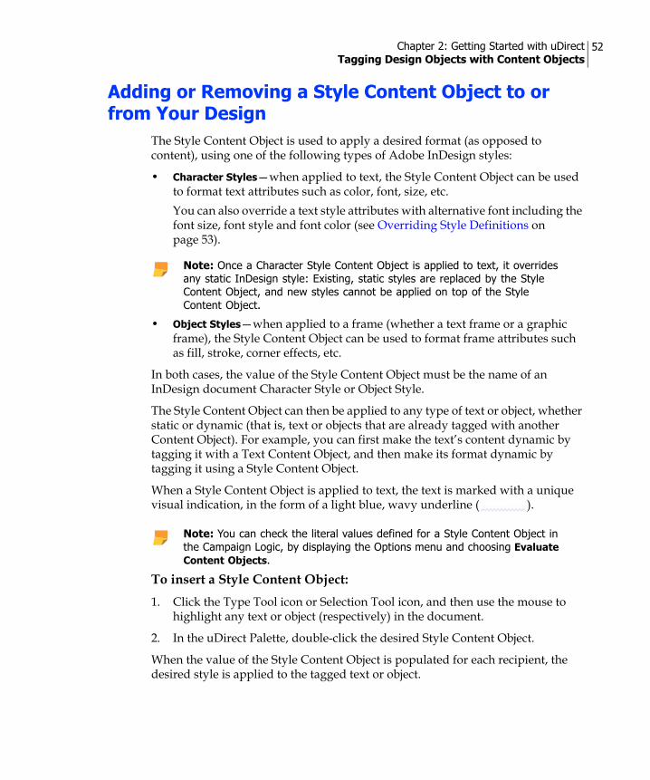
Chapter 2: Getting Started with uDirect Tagging Design Objects with Content Objects
52
Adding or Removing a Style Content Object to or from Your Design
The Style Content Object is used to apply a desired format (as opposed to content), using one of the following types of Adobe InDesign styles:
• Character Styles—when applied to text, the Style Content Object can be used to format text attributes such as color, font, size, etc.You can also override a text style attributes with alternative font including the font size, font style and font color (see Overriding Style Definitions on page 53).
• Object Styles—when applied to a frame (whether a text frame or a graphic frame), the Style Content Object can be used to format frame attributes such as fill, stroke, corner effects, etc.
In both cases, the value of the Style Content Object must be the name of an InDesign document Character Style or Object Style.
The Style Content Object can then be applied to any type of text or object, whether static or dynamic (that is, text or objects that are already tagged with another Content Object). For example, you can first make the text’s content dynamic by tagging it with a Text Content Object, and then make its format dynamic by tagging it using a Style Content Object.
When a Style Content Object is applied to text, the text is marked with a unique visual indication, in the form of a light blue, wavy underline ( ).
To insert a Style Content Object:1. Click the Type Tool icon or Selection Tool icon, and then use the mouse to
highlight any text or object (respectively) in the document.
2. In the uDirect Palette, double-click the desired Style Content Object.
When the value of the Style Content Object is populated for each recipient, the desired style is applied to the tagged text or object.
Note: Once a Character Style Content Object is applied to text, it overrides any static InDesign style: Existing, static styles are replaced by the Style Content Object, and new styles cannot be applied on top of the Style Content Object.
Note: You can check the literal values defined for a Style Content Object in the Campaign Logic, by displaying the Options menu and choosing Evaluate Content Objects.

Chapter 2: Getting Started with uDirect Tagging Design Objects with Content Objects
53
To remove a Style Content Object:To remove a Style Content Object (that is, remove the Character Style or Object Style without removing the text or object itself), proceed as follows:
1. Click the Type Tool icon or Selection Tool icon, and then use the mouse to highlight the text or object (respectively) to which a Style Content Object is applied.
2. Right-click the highlighted Style Content Object, and select Unapply Style Content Object ‘<Style Name>’ from the context menu. The Style Content Object is removed from the selected text or object (as indicated by the removal of the wavy underline).
Overriding Style DefinitionsIn a Style Content Object, you can override InDesign style definitions with
alternative font size, font style, and font color. By clicking the plus sign next to the Apply Style drop-down list of the Edit Content Object dialog, you can select your choice of style overrides in the Style Overrides dialog.
To override style definitions:1. In the uDirect Palette (Figure 10 on page 15), select an existing Content
Object, right-click and select Edit Rule.The Edit Content Object dialog is displayed (Figure 37).

Chapter 2: Getting Started with uDirect Tagging Design Objects with Content Objects
54
2. From the Type drop-down list, select Style.
3. Click the plus sign next to the Apply Style drop-down list.The Style Overrides dialog is displayed (Figure 38).
4. Select the checkbox of the formatting style you want to override, and from the adjacent drop-down list, select the required style.
5. Click OK.
Figure 37: Edit Content Object dialog
Figure 38: Style Overrides dialog

Chapter 2: Getting Started with uDirect Tagging Design Objects with Content Objects
55
Figure 44 on page 64 shows an example where the InDesign style original properties were overridden with custom properties, as follows: the font family was changed to Times New Roman (Regular font style), the font size was changed to 24 pt and its color to Black. These settings will take effect regardless of what is defined in the InDesign Style as specified by the Style Content Object. Other definitions in the InDesign Style will not be altered.
Tagging a Design Object with a Table Content ObjectThe Table Content Object consists of columns. The column types may be Text, Text File or Graphic Content Objects. The recipient-specific values of these Content Objects are typically extracted from a secondary Data Source, and not from the main Data Source. For example, the main Data Source serves as the Recipient List, and the secondary Data Source provides additional information on each recipient, such as their monthly use of cellular phones.
The same Table Content Object data may be displayed in your document in two different formats: tabular (Using a Table Content Object as a Table on page 55) or graphic (see Chapter 4: Dynamic Properties of Design Objects on page 98), depending on whether the Table Content Object is assigned to a text frame or to a graphic frame (respectively). The resulting tables are known as dynamic tables, and the resulting images are known as data driven graphics (see Appendix B: Working with uChart on page 188).
Using a Table Content Object as a Table
You can insert a Table Content Object into your design in two different ways:
• Create a new dynamic table, using a Table Content Object.
• Apply a Table Content Object to an existing, static InDesign table.
In both cases, note that in addition to the Content Objects assigned to the dynamic table’s columns, you may assign other Content Objects and static design elements to the dynamic table’s cells.
Note: For Color override, you can select between the Named colors option, which includes a list of color presets, and the Unnamed colors option, which allows you to define the color CMYK values
Note: Double clicking the Table Content Object’s icon in the uDirect Palette displays its columns, while double clicking the table Content Object’s name assigns it to the selected frame.

Chapter 2: Getting Started with uDirect Tagging Design Objects with Content Objects
56
To create a new dynamic table:1. Click the Type Tool icon, and then use the mouse to draw a rectangular area
in the document. Alternatively, you can place the cursor in an existing text box in the document.
2. In the uDirect Palette, double-click the name of the desired Table Content Objects. The Dynamic Table Properties dialog is displayed (Figure 39).
3. Make any necessary modifications, as explained in the Dynamic Table Properties dialog description at the end of this section.
4. Click OK to close the Dynamic Table Properties dialog. A dynamic table is inserted into your document, with the selected Table Content Object assigned to it, and the Table Content Object’s columns automatically added into the first Mold row.
5. Design the Mold row(s) as required: You can move the assigned column objects from cell to cell; add Text, Text File or Graphic Content Objects; and add static design elements.
6. When the Table Content Object column values populate the dynamic table, the static and dynamic elements in the Mold rows are duplicated in all Mold row instances throughout the dynamic table.
Figure 39: Dynamic Table Properties dialog
Note: Dynamic tables are marked by a light blue adornment, which surrounds the table’s Mold row(s) and includes a table icon and the Table Content Object’s name (for example, “ValuePerIndustry”, as shown in Figure 62).

Chapter 2: Getting Started with uDirect Tagging Design Objects with Content Objects
57
7. The Dynamic Table Properties dialog includes the following fields and options:
To access the properties of an existing dynamic table object:1. Within the Table Content Object, make a text selection and right-click the
mouse button.
2. Select Dynamic Table from the context menu and then select Dynamic Table Properties. The Dynamic Table Properties dialog is displayed.
3. Make any necessary modifications to the properties, and click OK to close the dialog.
Figure 40: Dynamic Table Mold Row(s) Adornment
Select this option… To…
Number of Mold Rows Specify how many of the first rows in this table form a pattern, after which all subsequent rows are to be molded.
Limit Mold Rows Instances
Specify the largest number of Mold row instances allowed per recipient. Use this option when you wish to show only a few entries, out of all entries that may be displayed for a specific recipient.
Show Columns in Header Row
Include the names of the Table Content Object’s columns in this table’s header row.This option is available only when you add a table Content Object (and not when editing the Dynamic Table Properties).
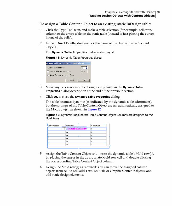
Chapter 2: Getting Started with uDirect Tagging Design Objects with Content Objects
58
To assign a Table Content Object to an existing, static InDesign table:1. Click the Type Tool icon, and make a table selection (for example, cell, row,
column or the entire table) in the static table (instead of just placing the cursor in one of the cells).
2. In the uDirect Palette, double-click the name of the desired Table Content Objects. The Dynamic Table Properties dialog is displayed.
3. Make any necessary modifications, as explained in the Dynamic Table Properties dialog description at the end of the previous section.
4. Click OK to close the Dynamic Table Properties dialog. The table becomes dynamic (as indicated by the dynamic table adornment), but the columns of the Table Content Object are not automatically assigned to the Mold row(s), as shown in Figure 42.
5. Assign the Table Content Object columns to the dynamic table’s Mold row(s), by placing the cursor in the appropriate Mold row cell and double-clicking the corresponding Table Content Object column.
6. Design the Mold row(s) as required: You can move the assigned column objects from cell to cell; add Text, Text File or Graphic Content Objects; and add static design elements.
Figure 41: Dynamic Table Properties dialog
Figure 42: Dynamic Table before Table Content Object Columns are assigned to the Mold Rows

Chapter 2: Getting Started with uDirect Tagging Design Objects with Content Objects
59
7. When the Table Content Object column values populate the dynamic table, the static and dynamic elements in the Mold rows are duplicated in all Mold row instances throughout the dynamic table.
Note: Copy fitting can be applied to table cells. Table copy fitting inherits its settings from the copy fitting that was applied to the dynamic story, in which the table is placed. For more information on copy fitting functionality, refer to Dynamic Story Length Handling on page 100.

Chapter 3
Managing Content ObjectsThis chapter explains how to manage your Content Objects.
Adding or Editing Content Objects using the Rule Editor
Content Objects are defined based on a number of attributes; their name, their type, and their business rule (Rule, in short). A Rule is an expression that is part of the Campaign Logic, and defines how to calculate the Content Object’s value for each recipient.
When you link your Document to a Data Source, uDirect automatically creates a Content Object for each column header in that Data Source. You may wish to manually edit these Content Objects, or create new ones, to tag your Design with dynamic formatting, conditional Rules or arithmetic operations. Content Objects are both edited and created using the Rule Editor.
The Rule Editor is a simple graphic user interface, consisting of basic drop-down lists and text boxes. It is specifically designed to allow non-technical users to easily define or modify Content Object Rules.
To launch the Rule Editor:You can launch the Rule Editor in one of the following ways:
• To add a new Content Object—right-click anywhere in the uDirect Palette and select New Content Object… from the context menu. The Rule Editor’s New Content Object dialog is displayed.
• To edit an existing Content Object—select the Content Object you wish to edit in the uDirect Palette and then select Edit Rule… from the context menu. The Rule Editor’s Edit Content Object dialog is displayed.
Note: The operations described in this chapter apply to Documents whose Content Objects were created via the Link to Data Source… or Link to Counter… options of the uDirect Options menu (and not via the Link to uPlan… option).

Chapter 3: Managing Content Objects Adding or Editing Content Objects using the Rule Editor
61
Figure 43 on page 62 shows an example Rule Editor window, used to edit a Text Content Object (First Name). The drop-down lists have been collapsed to reveal the available options.
The Rule Editor includes two main sections:
• Content Object Properties (top section) — for example, Name (in this case, First Name) and Type (in this case, Text). These options are described in on.
• Rule Definitions (bottom section) — a Rule is an expression that calculates this Content Object’s value for each recipient. The Rule is defined using the following drop-down lists:
• Rule type (the first list) — determines whether this Rule sets a Value or a condition (If).
• Rule building blocks (the second list) — literal values (string or number), functions (common and extended), and an alphabetical list of the Data Source columns.
• Operations (the third list)—operations, such as “+”, “-” etc. When you define a condition (by setting the first drop-down list to “If”), the operations list is enhanced with comparison operators, such as “AND”, “OR” etc.The Rule Definitions vary, depending on the Type of Content Object you are currently editing or adding (Text, Graphic etc.). These options are described in Rule Definitions on page 63.

Chapter 3: Managing Content Objects Adding or Editing Content Objects using the Rule Editor
62
Content Object PropertiesThe top section of the Rule Editor allows you to view and edit the following Content Object options:
Figure 43: Rule Editor—Edit Content Object “First Name”
Option Description
Name The name of this Content Object, displayed next to its icon in the uDirect Palette. If you selected the Link to Data Source…, uDirect automatically creates a Content Object for each column header in the linked Data Source.
Type The Content Object’s type: Text, Text with Style, Text File, Graphic, Visibility, Style or Table. The type determines which options are available in the Rule Editor. For details, see Rule Definitions on page 63.
Annotation Optional, descriptive text, providing useful information on this Rule. Note that his annotation is not shown anywhere else and is intended for users who wish to record their own comments.

Chapter 3: Managing Content Objects Adding or Editing Content Objects using the Rule Editor
63
Rule DefinitionsThe Rule Editor helps you set up different Rules by offering building blocks that are appropriate for the Type of Content Object currently being created or edited.
For example:
• If you are defining a Text Content Object, the Rule Editor prompts you to enter a value for the text string or number. You can also assign a specific style to the string.
• If you are editing a Graphic or Text File object, the Rule Editor prompts you to enter a direct file path or one that is relative to the InDesign document.
• For Visibility Content Objects, the Rule Editor instructs you to define a condition that will render the object visible or invisible.
• If you are editing a Style Content Object of a character style, the Rule Editor instructs you to define the style you want to apply to the text. You can also override InDesign style attributes with alternative font size, font style, and
font color by clicking the plus sign next to the Paragraph Style list and selecting your choices of style overrides in the Style Overrides dialog.
Campaign Dial Check to mark this Content Object as a Campaign Dial, thereby making it available for modification via uStore®. The uStore Admin application enables administrators to choose which of the available Dials are to be accessible via the uStore Customer application, so that customers can customize their values. For details, see the uStore Administrator’s Guide.
Extended Functions
Check this box to view all available functions in the functions drop-down list, instead of just the most commonly-used functions.
View QLingo… Opens a dialog allowing advanced users to view and edit the Content Object’s Rule definition as a QLingo expression.
Option Description

Chapter 3: Managing Content Objects Adding or Editing Content Objects using the Rule Editor
64
Figure 44 shows an example where the InDesign style original properties were overridden with custom properties, as follows: the font family was changed to Times New Roman (Regular font style), the font size was changed to 24 pt and its color to Black. These settings will take effect regardless of what is defined in the InDesign Style as specified by the Style Content Object.
The Rule Editor’s fields are menu-driven. Any time you make a menu selection, the subsequent interface options reflect the current options available, based on your selection. For example, if you are defining a conditional expression, the first line of the expression will end with a menu containing a list of condition operators (for example, AND, OR, =, >, <…).
Rule Building BlocksThe building blocks you can select from the drop-down menus include:
• Conditions—used to compare expressions made up of database fields and literal values. Use the AND/OR to add more than one comparison expression.
• Values—used to define the value expression as a concatenation or calculation of database fields and literal values.
• Functions—used to easily define rules by performing conversions and manipulations on the Data Source values. For a complete list of the uDirect functions, see Appendix A: Rule Editor Expressions.
Figure 44: Style Overrides dialog
Note: For Color override, you can select between the Named colors option, which includes a list of color presets, and the Unnamed colors option, which allows you to define the color CMYK values.

Chapter 3: Managing Content Objects Adding or Editing Content Objects using the Rule Editor
65
Example Content Object RulesThis section provides a few simple examples that demonstrate how to define Content Objects using the Rule Editor.
Defining a Text Content Object: Example 1In this example, our Data Source includes an ‘Age’ field. Our purpose is to associate the ‘Age’ numerical data with appropriate descriptive text (for example, ‘child’, ‘teen’, ‘adult’, etc.).
To do so, we will define a rule that determines the value of a Text Content Object that describes the recipient’s age. A person whose ‘Age’ value is less than 13 will be noted as a ‘child’. If they are younger than 20, but older than 13, they will be considered a ‘teen’. All other recipients, whose ‘Age’ value does not fit into one of the above categories, will be considered an ‘adult’.[If] [Age] [<] [Number] {13} [ ]
Then value = [String] {Child} [ ]
[Else if] [Age] [<] [Number] {20} [ ]
Then value = [String] {Teen} [ ]
[Else value=] [String] {Adult} [ ]
Defining a Text Content Object: Example 2In this example, our Data Source includes fields such as ‘first name’, ‘last name’, ‘age’, ‘gender’, ‘number of purchases’, and so forth. Our purpose is to design a short note that will be printed out and handed to shoppers when they pay for their groceries. For shoppers who are above the age of 20 and have shopped at the store more than 10 times, the note will offer a 25% discount the next time they shop at the store. Shoppers who do not fit this profile will get a message wishing them a nice day.
To accomplish this, we need to create a Text Content Object called Discount (Figure 45 on page 66). The value of this Text Object will be either the discount coupon or the message ‘Have a nice day’.[If] [Age] [>] [Number] {20}
[AND] [#Purchases] [>] {10}
Then value = [First Name] [&] [String] {Save 25% next time}
[Else value =] [String] {Have a nice day}
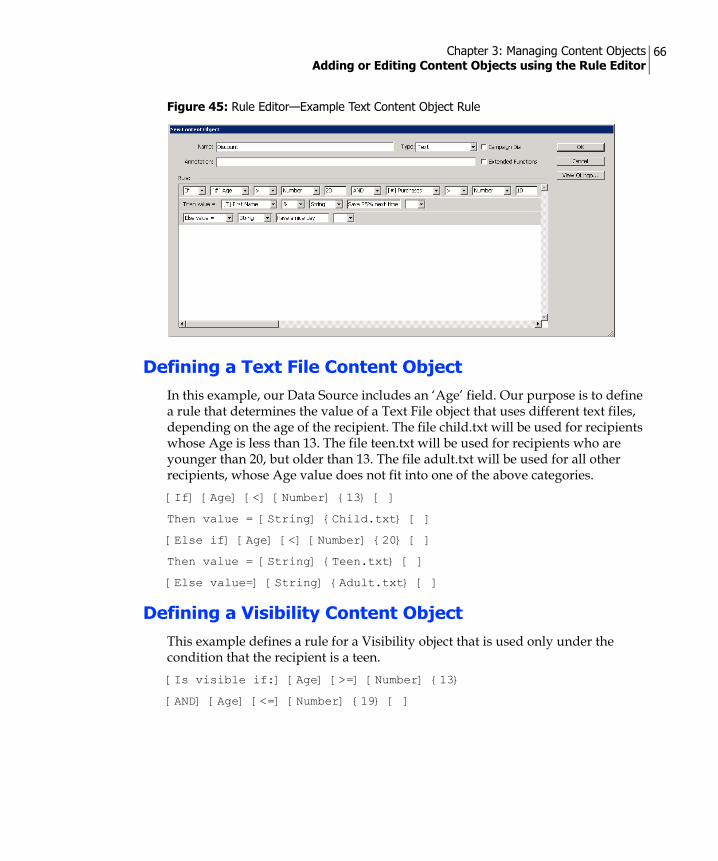
Chapter 3: Managing Content Objects Adding or Editing Content Objects using the Rule Editor
66
Defining a Text File Content ObjectIn this example, our Data Source includes an ‘Age’ field. Our purpose is to define a rule that determines the value of a Text File object that uses different text files, depending on the age of the recipient. The file child.txt will be used for recipients whose Age is less than 13. The file teen.txt will be used for recipients who are younger than 20, but older than 13. The file adult.txt will be used for all other recipients, whose Age value does not fit into one of the above categories.[If] [Age] [<] [Number] {13} [ ]
Then value = [String] {Child.txt} [ ]
[Else if] [Age] [<] [Number] {20} [ ]
Then value = [String] {Teen.txt} [ ]
[Else value=] [String] {Adult.txt} [ ]
Defining a Visibility Content ObjectThis example defines a rule for a Visibility object that is used only under the condition that the recipient is a teen.[Is visible if:] [Age] [>=] [Number] {13}
[AND] [Age] [<=] [Number] {19} [ ]
Figure 45: Rule Editor—Example Text Content Object Rule

Chapter 3: Managing Content Objects Adding or Editing Content Objects using the Rule Editor
67
Defining a Table Content ObjectTable Content Objects address the need to include recipient information from multiple Data Sources in a single Document. Each Table Content Object is used to extract data from a newly specified Data Source, in addition to the Data Source to which your Document is currently linked.
To create a Table Content Object, the new Data Source and the linked Data Source must share at least one unique key, that is: a table column header that uniquely identifies each recipient, such as a social security number; passport number; driver’s license number; email, etc.
You can then use the Rule Editor to choose the desired Data Source and map one of its column headers to the corresponding column header in your linked Data Source.
In the following example, the Document is linked to a Data Source named “Owners.txt”, containing the recipients’ personal details. Our goal is to associate this Document with an additional Data Source “Purchases.txt”, which contains each recipient’s stock purchases.
Both Data Sources share a column header named “Owner ID”. This common key allows us to define a Table Content Object Rule, which points to the Purchases.txt Data Source and maps its Owner ID field to the matching Owner ID field of the Owners.txt Data Source.
Based on this mapping, the new Rule can calculate the Table Content Object’s value for each recipient, resulting in a table where each row specifies a particular stock purchase made by the given recipient.
To add a new Table Content Object (for example, the “Purchases” Table Content Object):1. Right-click anywhere in the uDirect Palette and select New Content Object…
from the context menu. The Rule Editor’s New Content Object dialog is displayed (Figure 45 on page 66).
2. In the New Content Object dialog, go to the Type drop-down list and select Table.The Rule section of the dialog is replaced by a Table Structure and Data Information section.
3. In the Table Structure and Data Information section, go to the Source field and click Browse…
The Select Data Source dialog is displayed (Figure 46 on page 68).
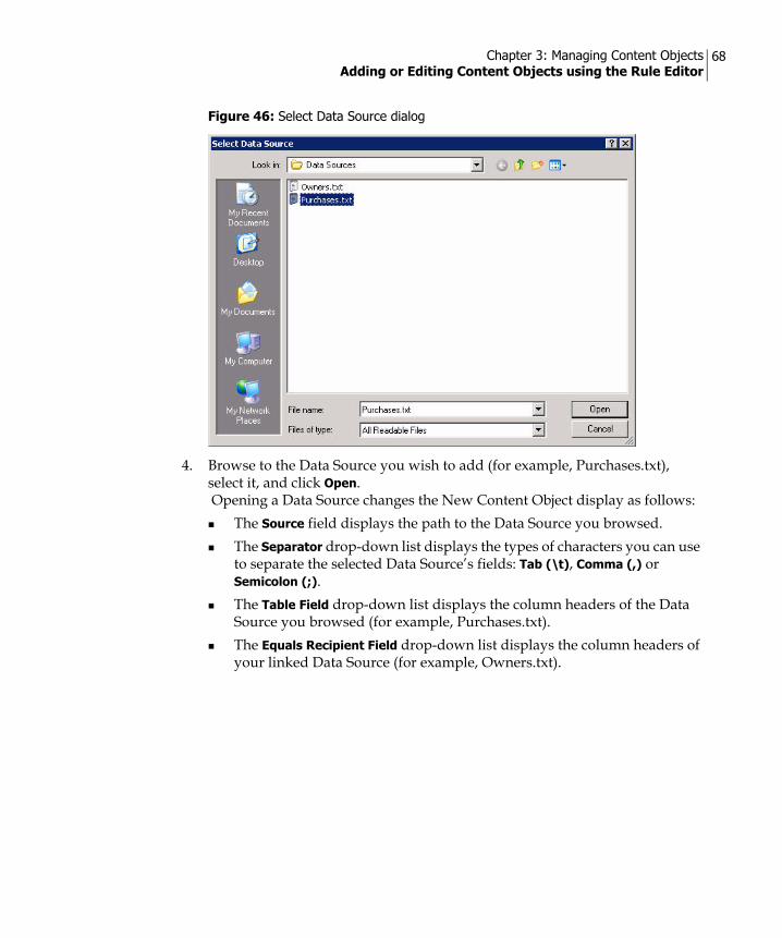
Chapter 3: Managing Content Objects Adding or Editing Content Objects using the Rule Editor
68
4. Browse to the Data Source you wish to add (for example, Purchases.txt), select it, and click Open. Opening a Data Source changes the New Content Object display as follows:
The Source field displays the path to the Data Source you browsed.The Separator drop-down list displays the types of characters you can use to separate the selected Data Source’s fields: Tab (\t), Comma (,) or Semicolon (;).The Table Field drop-down list displays the column headers of the Data Source you browsed (for example, Purchases.txt).The Equals Recipient Field drop-down list displays the column headers of your linked Data Source (for example, Owners.txt).
Figure 46: Select Data Source dialog

Chapter 3: Managing Content Objects Adding or Editing Content Objects using the Rule Editor
69
5. Map a unique key in the new Data Source to a corresponding key in the linked Data Source:
a. Select a column header from the Table Field drop-down list (for example, Owner ID).
b. Select the column you wish to associate it with from the Equals Recipient Field drop-down list (for example, Owner ID).
6. Click OK.The New Content Object dialog is closed, and the new Purchases Table Content Object is added to the uDirect Palette (Figure 43 on page 62).
Figure 47: Rule Editor—Table Content Object

Chapter 3: Managing Content Objects Adding or Editing Content Objects using the Rule Editor
70
Figure 48: uDirect Palette—New Table Content Object (Purchases)

Chapter 3: Managing Content Objects Using uImage in uDirect Studio
71
Using uImage in uDirect StudioGraphic Content Objects personalize your Document by displaying recipient-specific images. Regular Graphic Content Objects allow you to display different images for different recipients. For example, in a phone upgrade Campaign, each recipient may receive an image of his or her phone model (Figure 49).
uDirect Studio further personalizes your Document with Graphic Content Objects that use XMPie uImage. uImage Graphic Content Objects embed personalization into the image itself. The embedded personalization may include text, images or both. For example, Figure 50 shows the same base image, personalized for two recipients by embedding recipient-specific text: the recipient's first name, Bo or Christiana.
Figure 51 shows the same base image, personalized for two recipients by embedding recipient-specific images: a photo of a family or a photo of people in a boat.
Figure 49: Regular Graphic Content Object Images-Different Images (Phone Models) for Different Recipients
Figure 50: uImage Graphic Content Object Images-A Base Image Personalized with Recipient-Specific Text
Figure 51: uImage Graphic Content Object Images-A Base Image Personalized with Recipient-Specific Images

Chapter 3: Managing Content Objects Using uImage in uDirect Studio
72
Such personalization, embedded seamlessly into images, can greatly enhance your Design.
The basic workflow for using uImage with uDirect Studio includes two main procedures:
1. Adding Dynamic Content Tags to an Image (Photoshop or Illustrator) on page 72
2. Defining the Dynamic Content of uImage Tags (uDirect Studio in InDesign) on page 75
Adding Dynamic Content Tags to an Image (Photoshop or Illustrator)
uImage is XMPie software that allows designers to automate the image personalization process. The designer creates a uImage Template: a Photoshop or Illustrator file, which uses layers and special effects to embed text and/or images into a base image. One or more of the Template's layers are tagged with uImage Tags: placeholders for personalized values, which may be either text or images. The Rule for calculating a Tag's value per-recipient is defined in uDirect Studio (see "Defining uImage Tag Rules" on page 83). During production, uImage locates and replaces these Tags with each recipient's personalized values.
Defining Placeholders for Personalized TextThe designer adds personalized text to the uImage Template as part of a layer. This layer may be either a Smart Object layer or a Point text layer (as opposed to a Paragraph text layer, which does not allow copy fitting to work properly).
The layer's text contains the required uImage Tag: plain text with special syntax, enclosed by angle brackets (<,>). This syntax enables uImage to identify and replace the Tag with dynamic content. In addition, the layer may include static text (optional).
For example, the images in Figure 50 on page 71 were created using a uImage Template named Green Frog - HighRes.psd, shown in Figure 52 on page 73.This uImage Template includes an example base image (a green frog and text), personalized with a Point text layer named first. This layer includes the uImage Tag <FIRST NAME>, which serves as a placeholder for the recipient's first name, followed by a comma (static text). The Rule for calculating the <FIRST NAME> Tag's value is defined in uDirect Studio. During production, uImage executes this Rule, replacing the Tag with each recipient's name.

Chapter 3: Managing Content Objects Using uImage in uDirect Studio
73
Defining Placeholders for Personalized ImagesThe designer adds personalized images to the uImage Template as part of a Smart Object layer. The layer name is a uImage Tag, serving as a placeholder for a personalized image.
For example, the images in Figure 51 on page 71 were created using a uImage Template named Film - HighRes.psd, shown in Figure 53 on page 74. This uImage Template includes an example base image (hands holding a roll of film), personalized with a Smart Object layer named IMG. The layer's name, IMG, is a uImage Tag: it serves as a placeholder for a recipient-specific image.
The Rule for calculating the IMG Tag's value is defined in uDirect Studio. During production, uImage executes this Rule, replacing the Tag with a personalized photo: a family portrait or people in a boat (as shown in Figure 51).
Figure 52: Example uImage Template (Green Frog - HighRes.psd) with a Text Tag
Note: For personalized images, the uImage Tag name is the layer name. This name must NOT include angle brackets (they are required only when defining uImage Tags for text).

Chapter 3: Managing Content Objects Using uImage in uDirect Studio
74
For more information on defining the image's design in uImage, see the uImage User Guide.
Once you complete the image design, you can define its Logic (Rules). This procedure is performed in uDirect Studio, as explained in the following section.
Figure 53: Example uImage Template (Film - HighRes.psd) with a Image Tag

Chapter 3: Managing Content Objects Using uImage in uDirect Studio
75
Defining the Dynamic Content of uImage Tags (uDirect Studio in InDesign)
After Adding Dynamic Content Tags to an Image (Photoshop or Illustrator) (see page 72), you are required to define the dynamic content of these placeholders in uDirect Studio. This procedure includes the following steps:
1. Creating a uImage Graphic Content Object on page 75
2. Defining uImage Tag Rules on page 83.
3. Formatting the uImage Output Filename on page 85
4. Setting uImage Defaults (Optional) on page 92
Creating a uImage Graphic Content ObjectuDirect Studio allows you to include personalized images, generated by uImage from uImage Templates, in your Dynamic Document. This is done by adding a Graphic Content Object that references the uImage Template. The uImage Graphic Content Object defines all the settings required to use this Template in order to produce personalized images, for example: uImage file locations, copy fitting settings etc.
You can use this uImage Graphic Content Object just like any other Graphic Content Object, to tag relevant graphic(s) in your Document. During production, these tagged graphics are dynamically replaced with the uImage output files
To add a Graphic Content Object that references a uImage Template:1. Open your Document, right-click anywhere in the uDirect Palette and select
New Content Object… from the context menu..The Rule Editor’s New Content Object dialog is displayed (see Figure 45 on page 66).
2. In the Name field, enter a name for the new Content Object (for example, the name of the uImage Template it references).
3. From the Type drop-down list, select Graphic.
4. Check the Extended Functions checkbox.
5. In the Rule section, go to the functions drop-down list, select either uImage Photo for a Photoshop file, or uImage Illustration for an Illustrator file, and click Configure...
The uImage Settings dialog is displayed (Figure 54).

Chapter 3: Managing Content Objects Using uImage in uDirect Studio
76
6. Define the uImage settings of the Graphic Content Object as described in the table below:
Figure 54: uImage Settings dialog
Window Item Description
Template Document
The uImage Template (a Photoshop or Illustrator file, depending on the function chosen in the Rule Editor) that you wish to use, to create images with embedded personalization. Choose one of the following:• Click Browse… to locate the full path to the uImage Template.• Enter a relative path, to be appended to the default uImage
Templates folder (see "Setting uImage Defaults (Optional)" on page 92).
Output Folder The folder in which the uImage output files (the images with embedded personalization) will be stored. Choose one of the following:• Click Browse… to locate the full path to the uImage Output
folder.• Enter a relative path, to be appended to the default uImage
Output folder (see Output Format Properties on page 87).

Chapter 3: Managing Content Objects Using uImage in uDirect Studio
77
Output Format Select the format of the uImage output files (JPG, EPS etc.) from the drop-down list. To define the format settings, click Properties. A format-specific Properties dialog is displayed, allowing you to define the desired settings. For details, see Output Format Properties on page 87.
Copy Fitting For uImage Templates that embed recipient-specific text, specify how to handle cases of text overflow (exceeding the boundaries of the text frame) or underflow (leaving extraneous blank spaces). Overflow and underflow occur because different dynamic text values have different lengths. For example, the name “Jo” is much shorter than “Christopher”. In some Templates, the name “Jo” will fit into the text frame, while the name “Christopher” will overflow. Choose a Copy Fitting Mode and then choose a Copy Fitting Method (see below).
Copy Fitting Mode Select one of the following copy fitting modes from the list:• Off—disables the copy fitting feature. Select this mode if you do
not want the dynamic text to be manipulated in any way. Note that copy fitting is required to make sure variances in recipient data fit properly into the text frame.
• Overflow—automatically handles text overflow, by reducing it to the maximum size allowed by the uImage Template. If the text is shorter than the maximum size allowed, it remains unchanged.
• Overflow and Underflow—automatically stretches or condenses the text, so that it is exactly the maximum size allowed.
• Manual—uses the copy fitting settings defined in the uImage Template. For information on defining copy fitting settings within the uImage Template, see the uImage User Guide.
• Underflow—automatically handles text underflow, by enlarging it up to the maximum size allowed. This mode is rarely used, since it does not handle overflowing text: if text is longer than the maximum size allowed, it remains unchanged.
Window Item Description

Chapter 3: Managing Content Objects Using uImage in uDirect Studio
78
Copy Fitting Method
Once a Copy Fitting Mode is selected, choose one of the following methods:• Horizontal Scaling—handles text overflow and/or underflow
(depending on the Copy Fitting Mode), by either condensing or expanding the text horizontally. The font is distorted (appears narrower or wider than it should), but its height remains unchanged. Keeping the same height ensures the text does not overflow above or below its frame. For example, in Figure 55 below, handling the underflow with horizontal scaling stretches the text without overflowing into the image above it
• Font Size—handles text overflow or underflow by scaling the font proportionally (both horizontally and vertically). The font is not distorted; however, its height varies for different text lengths. When using one of the underflow copy fitting modes, height variations might cause the text to overflow above or below its frame. For example, in Figure 55, handing the underflow by increasing the font size caused the text to overflow into the image above it.
NOTE: The minimum and maximum font sizes allowed are defined by the uImage Template (for details, see the uImage User Guide).
Figure 55: Copy Fitting Modes—Underflow Handled with Font Size versus Horizontal Scaling
Data Define the Rules for calculating the values of the uImage Tags in this uImage Template. For each uImage Tag defined in the uImage Template, a matching uImage Tag Rule must be defined here.
Available Fields The fields of the linked Data Source, which may be used to define uImage Tag Rules. If a Tag is based on a Data Source field, you can easily define its Rule by selecting the relevant field and clicking Add… This Tag is added to the uImage Tags list with the same name as the field's name, and its default Rule is to take the field's value as-is from the Data Source. To edit the name or the Rule of a Tag that is based on an available field, select this Tag in the uImage Tags list and double-click, or click Customize... (see below).
Window Item Description
Font Size Horizontal Scaling

Chapter 3: Managing Content Objects Using uImage in uDirect Studio
79
uImage Tags The Rules for calculating the recipient-specific values of the uImage Tags in the uImage Template. Make sure you define a Rule for each Tag in the uImage Template. The name of the Tag's Rule in uDirect Studio must match the name of the Tag in the uImage Template (note that Tag names are NOT case-sensitive):• For text Tags, use the Tag's name in the uImage Template,
without the angle brackets that define the Tag in Photoshop and Illustrator.
• For image Tags, use the name of the Tag's Smart Object layer in Photoshop.
NOTE: If a uImage Tag is not listed here, or if it has different names in the uImage Template and in uDirect Studio, this Tag will not be personalized during production (the image will show the Tag's placeholder).You can define and edit uImage Tag Rules using one of the following methods:• Add a Tag based on a Data Source field–select a field in the
Available Fields list and double click, or click Add… By default, this Tag's name is the same as the field's name, and its Rule is to take the field's value as-is from the Data Source. To edit this Tag, select it and double click, or click Customize… (see below).
• Change a Tag's Rule–select the Tag in the uImage Tags list and click Customize… The Customize uImage Tag dialog is displayed, allowing you to rename the Tag and edit its Rule using a Rule Editor (see Defining uImage Tag Rules on page 83).
• Define a Tag starting with an empty Rule–click New… The New uImage Tag dialog is displayed, allowing you to define the Tag's name and its Rule using a Rule Editor (see Defining uImage Tag Rules on page 83).
• Delete a Tag that is NOT used in the uImage Template–select the Tag and click Remove… The Tag is deleted from the uImage Tags list.
Advanced Settings Specify whether a Photoshop or Illustrator Action or an external JavaScript file should be run during production, and format the uImage output file.An Action or JavaScript code may be used to integrate dynamic content into the personalized image. If an Action or JavaScript code was created by the uImage Template designer, they must be defined here for the personalized images to appear correctly. For more information on Actions and JavaScript, see the uImage User Guide.NOTE: Hide Advanced Settings changes to Show Advanced Settings when clicked.
Window Item Description

Chapter 3: Managing Content Objects Using uImage in uDirect Studio
80
Automatically Play Choose whether to automatically play an Action or JavaScript during production. Choose one of the following:• None—the uImage Template will be produced without running
any JavaScript or Action. This is the default setting.• Action—select the Photoshop or Illustrator Action to be played
back during production. Specify the name of the Folder containing this Action, and the name of the Action, as they appear in the Actions panel in Photoshop or Illustrator.
• JavaScript—select an external Photoshop JavaScript file to be run during production. Specify the file's location in the Path text box, or click Browse… to locate the file
Folder If you Automatically Play an Action, specify the name of the Photoshop or Illustrator Folder (Set) containing this Action, as it appears in the Actions panel in Photoshop or Illustrator.
Action If you Automatically Play an Action, specify the name of this Action, as it appears in the Actions panel in Photoshop or Illustrator.
Output Filename Format
Defines the format of the uImage output filenames. A uImage output file is created for each recipient. Its name typically includes the name of the template followed by the recipient's values for all Tags in the Template. As a result, identical images that share the same values receive the same filename. This enables proper operation of the Skip Duplicates functionality (see below).
Automatic uImage automatically names each uImage output file, using the uImage Template's name followed by the values of the Tags on the uImage Tags list. The default naming convention is: <uImage Template Name>_<uImage Tag 1 Value>_<uImage Tag 2 Value>..._<uImage Tag n Value>.<Format Extension>For example, when using the Green Frog - HighRes.psd Template (Figure 52 on page 73), which includes the Tag <First Name>, Bo and Christiana's automatic filenames are as follows:• Green Frog - HighRes.psd_Christiana.jpg• Green Frog - HighRes.psd_Bo.jpg
Window Item Description

Chapter 3: Managing Content Objects Using uImage in uDirect Studio
81
7. Click OK to close the dialog.The uImage Template properties are displayed in the New Content Object dialog (Figure 56 on page 82).
Custom Customize the format of the uImage output file names. Click Customize… to open the uImage Output Filename Format dialog (Figure 58 on page 86), and define a Rule for the file name. For example, you can set a specific uImage Tag (such as the recipient's name) to appear in uppercase. For details, see Formatting the uImage Output Filename on page 85.
Skip Duplicates Enables you to optimize production, provided that the Output Filename Format (see above) reflects the values used in all uImage Tags. That is, if two recipients' data create the same personalized image, the Output Filename Format will create the same filename for both recipients. This enables uImage to detect which personalized images are duplicates, and to skip them if this check box is checked. Choose one of the following:• Check this box to skip output filenames that have already been
processed (this is the default setting). • Leave this box unchecked to force uImage to generate images
even though they already exist in the uImage Output Folder. When using Dynamic Print, it is recommended to optimize production speed, by checking this box and setting the Output Filename Format to Automatic.
Window Item Description
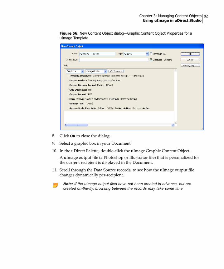
Chapter 3: Managing Content Objects Using uImage in uDirect Studio
82
8. Click OK to close the dialog.
9. Select a graphic box in your Document.
10. In the uDirect Palette, double-click the uImage Graphic Content Object.A uImage output file (a Photoshop or Illustrator file) that is personalized for the current recipient is displayed in the Document.
11. Scroll through the Data Source records, to see how the uImage output file changes dynamically per-recipient.
Figure 56: New Content Object dialog—Graphic Content Object Properties for a uImage Template
Note: If the uImage output files have not been created in advance, but are created on-the-fly, browsing between the records may take some time

Chapter 3: Managing Content Objects Using uImage in uDirect Studio
83
Defining uImage Tag RulesThe Rules of uImage Tags are not defined in the uImage Template, but in uDirect Studio, using the uImage Settings dialog. When working in the uImage Settings dialog, you must define Rules for all Tags in the uImage Template, and use the exact same names defined in the uImage Template:
• For text Tags, the Tag's name in uDirect Studio must match the Tag's content in the uImage Template, without the angle brackets that define the Tag's format in Photoshop and Illustrator (for example: “First Name” in Figure 52 on page 73).
• For image Tags, the Tag's name in uDirect Studio must match the Tag's name in the uImage Template (for example, “IMG” in Figure 53 on page 74).
The uImage Settings dialog (Figure 54 on page 76) includes a uImage Tags list, which names all Tags to be replaced with personalized data, and defines the Rules for calculating the recipient-specific values passed to uImage.
For text Tags, the Tag's Rule typically replaces the placeholder with a recipient-specific value of a Data Source field (such as “First Name”). To define such a Rule, simply select the relevant Data Source field and click Add…
Alternatively, you can use uDirect Studio's Rule Editor do define custom Tag Rules, just like Content Object Rules. The Tag Rules may include multiple Data Source fields and use conditional logic and data manipulation functions. For example, you can define an <Age> uImage Tag, who's Rule manipulates the “Birth Date” Data Source field to calculate the recipient's age.
To customize uImage Tags in uDirect Studio: 1. Access the uImage Settings dialog shown in Figure 54 on page 76 (open the
New Content Object or Edit Content Object dialog of the uImage Graphic Content Object and click Configure...).
2. In the Data section, go to the uImage Tags list, select the Tag you wish to edit and click Customize...
The Customize uImage Tag “<Tag Name>” dialog is displayed (Figure 57 on page 84).
Note: If a uImage Tag is not listed here, or if it has different names in the uImage Template and in uDirect Studio, this Tag will not be personalized during production (the image will show the Tag's placeholder).
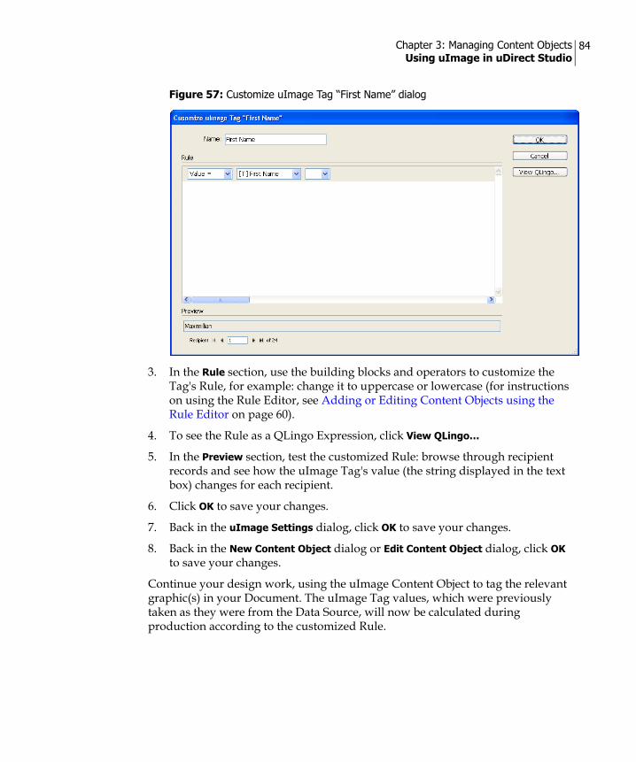
Chapter 3: Managing Content Objects Using uImage in uDirect Studio
84
3. In the Rule section, use the building blocks and operators to customize the Tag's Rule, for example: change it to uppercase or lowercase (for instructions on using the Rule Editor, see Adding or Editing Content Objects using the Rule Editor on page 60).
4. To see the Rule as a QLingo Expression, click View QLingo…
5. In the Preview section, test the customized Rule: browse through recipient records and see how the uImage Tag's value (the string displayed in the text box) changes for each recipient.
6. Click OK to save your changes.
7. Back in the uImage Settings dialog, click OK to save your changes.
8. Back in the New Content Object dialog or Edit Content Object dialog, click OK to save your changes.
Continue your design work, using the uImage Content Object to tag the relevant graphic(s) in your Document. The uImage Tag values, which were previously taken as they were from the Data Source, will now be calculated during production according to the customized Rule.
Figure 57: Customize uImage Tag “First Name” dialog

Chapter 3: Managing Content Objects Using uImage in uDirect Studio
85
Formatting the uImage Output FilenameDuring production, each uImage Content Object is replaced with uImage output files: personalized image files created per-recipient. The names of the uImage output files are determined by the Output Filename Format field of the uImage Settings dialog (Figure 54 on page 76).
The output filename plays an important role in production optimization: when uImage Tag values are reflected by the names of the uImage output files, identical output files receive the same name. Files with duplicate names can then be detected, enabling the Skip Duplicates functionality to avoid production of existing output. Setting the Output Filename Format to the Automatic option ensures that this happens.
The default uImage output filename format, created by the Automatic option, is as follows: <uImage Template Name>_<uImage Tag 1 Value><uImage Tag 2 Value>…<uImage Tag n Value>.<Format Extension>
For example, the uImage Template named Green Frog - HighRes.psd (Figure 52 on page 73) includes the first uImage Tag, whose content is <FIRST NAME>. This Template's output filename format is: Green Frog - HighRes.psd_<First Name>.jpg
This format creates different filenames for two of the recipients, Bo and Christiana: Green Frog - HighRes.psd_Bo.jpg versus Green Frog - HighRes.psd_Christiana.jpg. Since these filenames are different, uImage produces both files.
For any other recipient whose first name is either “Bo” or “Christiana”, the filename will be identical. If Skip Duplicates is checked, the personalized image will not be produced again, resulting in significantly quicker production times, especially for large recipient lists with many duplicate names.
The Output Filename Format drop-down list offers the following formatting options:
• Automatic—uImage will use the default filename format, which includes the values of all uImage Tags defined in the uImage Tags section of the uImage Settings dialog. If you do not have any special filename requirements, choose this option and make sure Skip Duplicates is checked.
• Custom—customize the Automatic (default) filename format using the uImage Output Filename Format dialog, as explained below.
Note: To accurately reflect the image's values, the output filename format must include ALL uImage Tags included in the image.
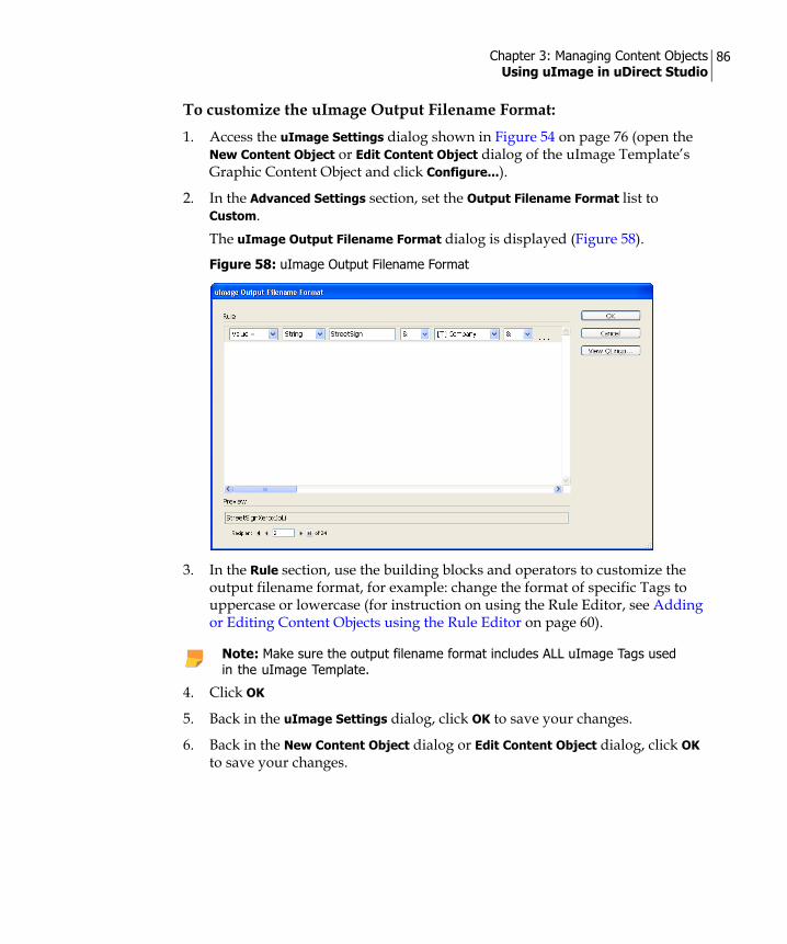
Chapter 3: Managing Content Objects Using uImage in uDirect Studio
86
To customize the uImage Output Filename Format:1. Access the uImage Settings dialog shown in Figure 54 on page 76 (open the
New Content Object or Edit Content Object dialog of the uImage Template’s Graphic Content Object and click Configure...).
2. In the Advanced Settings section, set the Output Filename Format list to Custom.The uImage Output Filename Format dialog is displayed (Figure 58).
3. In the Rule section, use the building blocks and operators to customize the output filename format, for example: change the format of specific Tags to uppercase or lowercase (for instruction on using the Rule Editor, see Adding or Editing Content Objects using the Rule Editor on page 60).
4. Click OK
5. Back in the uImage Settings dialog, click OK to save your changes.
6. Back in the New Content Object dialog or Edit Content Object dialog, click OK to save your changes.
Figure 58: uImage Output Filename Format
Note: Make sure the output filename format includes ALL uImage Tags used in the uImage Template.

Chapter 3: Managing Content Objects Using uImage in uDirect Studio
87
Continue your design work, using the uImage Graphic Content Object to tag the relevant graphic(s) in your Document. When you produce this Document, the uImage output filenames will have the specified format. If you have checked Skip Duplicates in the uImage Settings dialog, duplicated filenames will be detected and existing output will not be produced again.
Output Format Properties
Each application supports a number of file output formats as described in the table below:
Output Format Properties
Photoshop
JPEG (*.JPG)
Window Item Description
Quality Specifies the quality of the JPEG output file.The higher the number, the better the quality.

Chapter 3: Managing Content Objects Using uImage in uDirect Studio
88
Photoshop EPS (*.EPS)
Window Item Description
Save vector data Select this check box if vector data should be saved. This is relevant only if the image contains vector data.
Encoding Select the format in which the image data is saved.
JPEG Quality Specifies the JPEG quality, if JPEG is selected as the encoding option.
Output Format Properties

Chapter 3: Managing Content Objects Using uImage in uDirect Studio
89
Illustrator
JPEG (*.JPG)
Window Item Description
Quality Specifies the quality of the JPEG output file.
Clip to The clipping rectangle options for the output file. Options are Artboard or Small bounding box.
Optimize for the Web Select this check box to optimize the output file for the Web.
Illustrator EPS (*.EPS)
Window Item Description
Embed fonts Select this check box if you want to embed all fonts within the template.
Embed links Select this check box if you want to embed all links within the template.
Output Format Properties

Chapter 3: Managing Content Objects Using uImage in uDirect Studio
90
PNG (*.PNG)
Window Item Description
Clip to The clipping rectangle options for the output file. Options are Artboard or Small bounding box.
Output Transparency Select the check box to include transparency information in the output file.
Photoshop PSD (*.PSD)
Window Item Description
Resolution (dpi) Specifies the resolution of the PSD output file.
Output Format Properties

Chapter 3: Managing Content Objects Using uImage in uDirect Studio
91
Compuserve GIF (*.GIF)
Window Item Description
Clip to: The clipping rectangle options for the output file. Options are Artboard or Small bounding box.
Colors Specifies the number of colors in the output file.
Output Transparency Select the check box to include transparency information in the output file.
Adobe Illustrator
(*.AI)
Window Item Description
Embed Links Select this check box if you want to embed all links within the Template.
Output Format Properties

Chapter 3: Managing Content Objects Using uImage in uDirect Studio
92
Setting uImage Defaults (Optional)The uImage Defaults feature is an optional configuration, used in case different designers work at different workstations on the same Campaign, and need to share uDirect Studio InDesign Documents. The uImage Defaults dialog allows defining a single root folder (such as C:\Program Files\XMPie) for each type of uImage files: Templates, Outputs and Assets (in this context, Assets are images that are placed in uImage Tags as dynamic images).
To use this feature, you are required to enter relative paths to the uImage files defined in the uImage Settings dialog (Figure 54 on page 76), instead of clicking Browse… to locate the full path to these files. Each relative path is then appended to the relevant uImage default folder.
To set the uImage default folders:
1. In the uDirect Palette, click the icon and select Set uImage Defaults...The uImage Defaults dialog is displayed (Figure 59).
2. Define the uImage default folders are follows:
Note: uImage Defaults is a system-wide setting, which applies to all Documents containing a uImage Graphic Content Object.
Figure 59: uImage Defaults dialog
Window Item Description
Templates Folder The default folder containing uImage Templates (Photoshop or Illustrator files that include uImage Tags, for example: Film - HighRes.psd shown in Figure 53 on page 74).Click Browse… to locate the full path (or enter the full path) to the default Templates folder.

Chapter 3: Managing Content Objects Using uImage in uDirect Studio
93
3. To save these uImage default settings and close the dialog, click OK.
The uImage default folders are now defined. During production, the relative paths defined in the uImage Settings dialog (Figure 54 on page 76) will be appended to these default folders:
• The relative path to the Template Document will be appended to the default Templates Folder.
• The relative path to the Output Folder will be appended to the default Output Folder.
In addition, if uImage cannot find the path to a uImage Asset, it will append the uImage Asset's filename to the default Assets Folder.
Output Folder The default folder containing uImage output files (recipient-specific images with embedded personalization, for example: Film - HighRes.psd_Bo.jpg and Film - HighRes.psd_Christiana.jpg). Click Browse… to locate the full path (or enter the full path) to the default Output folder.
Assets Folder The default folder containing uImage Asset files (recipient-specific files, used by uImage to personalize a base image. For example: the photos of a family and of people in a boat, embedded in the Film Template shown in Figure 51 on page 71).Click Browse… to locate the full path (or enter the full path) to the default Assets folder.
Window Item Description
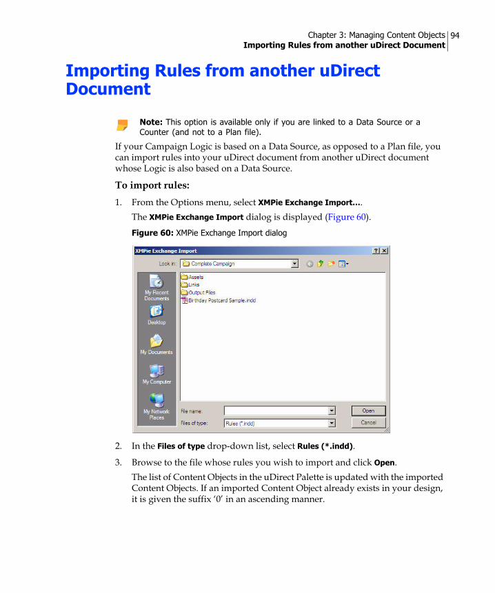
Chapter 3: Managing Content Objects Importing Rules from another uDirect Document
94
Importing Rules from another uDirect Document
If your Campaign Logic is based on a Data Source, as opposed to a Plan file, you can import rules into your uDirect document from another uDirect document whose Logic is also based on a Data Source.
To import rules:1. From the Options menu, select XMPie Exchange Import….
The XMPie Exchange Import dialog is displayed (Figure 60).
2. In the Files of type drop-down list, select Rules (*.indd).
3. Browse to the file whose rules you wish to import and click Open. The list of Content Objects in the uDirect Palette is updated with the imported Content Objects. If an imported Content Object already exists in your design, it is given the suffix ‘0’ in an ascending manner.
Note: This option is available only if you are linked to a Data Source or a Counter (and not to a Plan file).
Figure 60: XMPie Exchange Import dialog
Chapter 3: Managing Content Objects Renaming Content Objects
95
Renaming Content Objects
The Rename option enables you to change the name of the Content Objects used in your document.
To rename a Content Object:1. In the uDirect Palette, select the desired Content Object and then select
Rename from the context menu.
2. In the Name field, type the new name for your Content Object.
3. Click OK to save your changes and close the dialog. The new name is immediately reflected in the list of Content Objects.
Changing the Type of Content Objects
The Type option enables you to change the type of the Content Object currently selected in the uDirect Palette.
To change the type of a Content Object:1. In the uDirect Palette, select the desired Content Object and then select Type
from the context menu.
2. Select the desired type from the available options displayed. One of the following takes place:
If this Content Object is not assigned to any of your design objects, the command is executed, and the icon of the new type is immediately displayed in the list of Content Objects.If this Content Object is assigned to any of your design objects, a warning is displayed, notifying you that this operation will invalidate all
Note: It is possible to import Content Objects that refer to fields which do not exist in the data, but the missing fields will be marked as >>NoName<< in the “Edit Content Object” window.
Note: This option is available only if you are linked to a Data Source or a Counter (and not to a Plan file).
Note: This option is available only if you are linked to a Data Source or a Counter (and not to a Plan file).

Chapter 3: Managing Content Objects Duplicating a Content Object
96
references to this Content Object within the document (Figure 61 on page 96).
3. To proceed with the operation, click Change.The icon of the new type is immediately displayed in the list of Content Objects.
Duplicating a Content Object
The Duplicate option enables you to create an exact copy of a Content Object. You can then change the name of this copy and use it as a basis for a new Content Object, which can be further modified as necessary.
To duplicate a Content Object:In the uDirect Palette, select the desired Content Object and then select Duplicate from the context menu. A copy of the Content Object is displayed in the list. You can now proceed to rename the Content Object or make any necessary changes.
Deleting a Content Object
The Delete option enables you to remove a Content Object from your document. When you delete a Content Object, any instances of its use in your design document will no longer change dynamically.
Figure 61: Changing the Type of an Assigned Content Object—Warning
Note: This option is available only if you are linked to a Data Source or a Counter (and not to a Plan file).
Note: This option is available only if you are linked to a Data Source or a Counter (and not to a Plan file).

Chapter 3: Managing Content Objects Deleting a Content Object
97
To delete a Content Object:1. In the uDirect Palette, select the Content Object to be deleted and then select
Delete from the context menu. One of the following warnings is displayed:
If this Content Object is not assigned to any of your design objects, you are simply asked to confirm the deletion (Figure 62).
If this Content Object is assigned to any of your design objects, the warning notifies you that this operation will invalidate all references to this Content Object within the document (Figure 63).
2. To proceed with the operation, click Delete.The Content Object is removed from the uDirect Palette and from your design objects.
Figure 62: Deleting an Unassigned Content Object—Warning
Figure 63: Deleting an Assigned Content Object—Warning

Chapter 4
Dynamic Properties of Design Objects
Most dynamic design objects have an individual set of properties, which you can view and modify. This is done by selecting different elements of your design document and accessing their context menu. The following table summarizes access to some of the Content Object dynamic properties:
Dynamic Text PropertiesDynamic properties of Text objects display Content Object name and enable you to select a preference for non-breaking spaces and hyphenation.
To view dynamic text properties:1. Click the Text Content Object and right-click the mouse button.
2. Select Dynamic Text Properties from the menu displayed. The Dynamic Text Properties dialog is displayed.
3. If desired, select the option for space and hyphenation.
4. Click OK to close the dialog.
Select and right-click this… To access this…
Frame of Graphic Dynamic Object Dynamic Graphic Properties
Frame of dynamic story Dynamic Story Properties
Text in dynamic story Dynamic Story Properties
Text Dynamic Object Dynamic Story Properties and Dynamic Text Properties
Dynamic Story Specialty Imaging

Chapter 4: Dynamic Properties of Design Objects Dynamic Text File Properties
99
Dynamic Text File PropertiesDynamic properties for Text File objects display the name of the Content Object and enable you to set a preference for nested composition.
To view dynamic text properties:1. Click the Text Content Object and right-click the mouse button.
2. Select Dynamic Text Properties from the menu displayed. The Dynamic Text Properties dialog is displayed.
3. If you wish, select the option for nested composition.
4. Click OK to close the dialog.
Dynamic Story PropertiesDynamic Story Properties display properties related to the flow of dynamic text through one or more text frames. Depending on the length of text for various recipients, the flow may appear differently in the resulting customer communication and therefore may require automatic adjustment. uDirect uses the Story Properties to adjust the text flow within story frames.
To view or modify Story Properties, ensure that your document is already linked to a Data Source and that you have at least one Text Content Object or Text File Content Object within the story.
There are two types of Dynamic Story Properties:
• Suppress Trailing Spaces on Empty Content—discards the blank spaces left after Content Objects with empty string values.
• Dynamic Story Length Handling…—allows you to automatically adjust text that either overflows from the story frames, or underflows leaving an extraneous blank space. This feature enables you to specify how you want the text to fit into the story area by modifying the font size and auto-leading.
To view or modify Dynamic Story properties for a specific text frame:
1. Select the Type Tool icon, click anywhere inside the desired story text frame, and then right-click the mouse button.
2. Select Dynamic Story Properties from the context menu and then select either Suppress Trailing Spaces on Empty Content or Dynamic Story Length Handling…, as desired.

Chapter 4: Dynamic Properties of Design Objects Dynamic Story Properties
100
3. Make any necessary modifications as described below for the various story options.
Suppress Trailing Spaces on Empty Content The Suppress Trailing Spaces on Empty Content option automatically discards blank spaces that may be left after Content Objects that contain empty string values for a specific recipient.
For example, consider the following text fragment:Mr. [leading-blanks]{FirstName}[trailing-blanks]{LastName}
If for a given recipient (for example, Mr. Jones), the FirstName Content Object resolves to an empty string, the result may contain two spaces between the prefix (Mr.) and the last name (Mr.[][]Jones). Using this option, spaces that trail the empty Content Object are suppressed. This option also removes paragraphs that consist solely of empty Content Objects.
To suppress blank spaces that follow empty Content Objects:1. Click anywhere inside the desired story text frame and then right-click the
mouse button.
2. Select Dynamic Story Properties from the context menu and then select Suppress Trailing Spaces on Empty Content.
Dynamic Story Length HandlingDynamic Story Length Handling is used to activate the Copy Fitting and/or Auto Flow functions. These functions handle text whose length is dynamic (for example, Text File or Table Content Objects), and might overflow from one story frame to another.
• Copy Fitting—this feature is used to handle cases of text overflow or underflow (the latter creates extraneous blank spaces in your document). This feature allows you to specify how the text is to be fitted into the story area, by modifying the font size, font width and the auto leading.
• Auto Flow- this feature automatically adds the required number of pages to each recipient’s document, so that the story overflow fits into the auto-generated pages. The dynamic length story to which this feature is applied is known as an Auto Flow story.
When these features are activated, you are provided with a preview of the final results when you proof the data within your design.
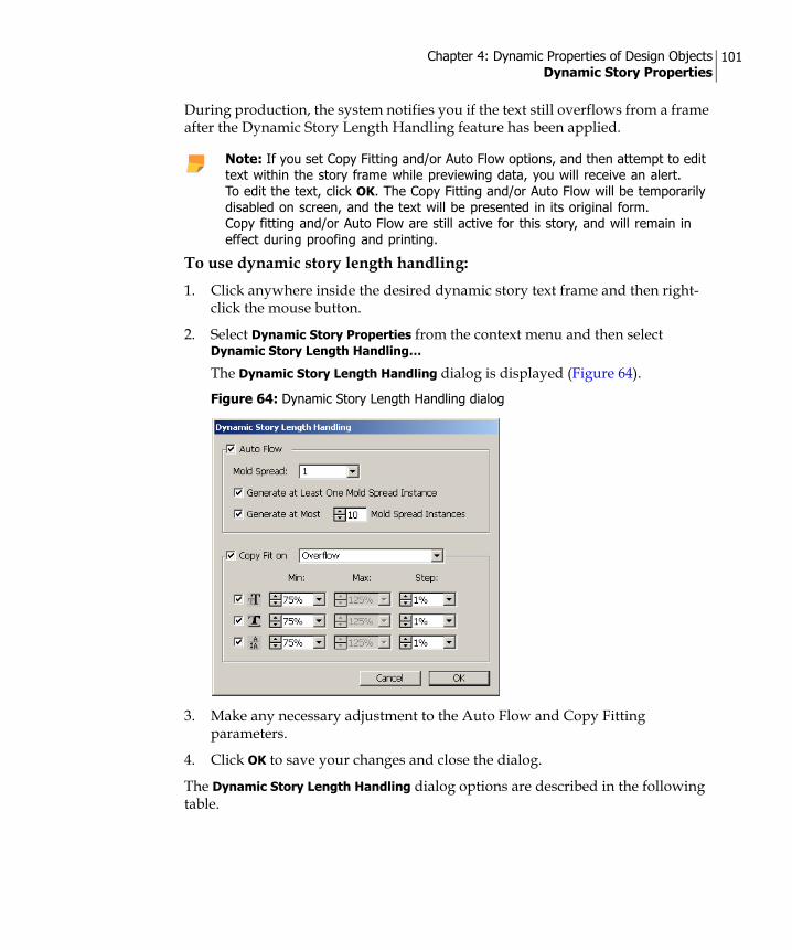
Chapter 4: Dynamic Properties of Design Objects Dynamic Story Properties
101
During production, the system notifies you if the text still overflows from a frame after the Dynamic Story Length Handling feature has been applied.
To use dynamic story length handling:1. Click anywhere inside the desired dynamic story text frame and then right-
click the mouse button.
2. Select Dynamic Story Properties from the context menu and then select Dynamic Story Length Handling…
The Dynamic Story Length Handling dialog is displayed (Figure 64).
3. Make any necessary adjustment to the Auto Flow and Copy Fitting parameters.
4. Click OK to save your changes and close the dialog.
The Dynamic Story Length Handling dialog options are described in the following table.
Note: If you set Copy Fitting and/or Auto Flow options, and then attempt to edit text within the story frame while previewing data, you will receive an alert. To edit the text, click OK. The Copy Fitting and/or Auto Flow will be temporarily disabled on screen, and the text will be presented in its original form. Copy fitting and/or Auto Flow are still active for this story, and will remain in effect during proofing and printing.
Figure 64: Dynamic Story Length Handling dialog

Chapter 4: Dynamic Properties of Design Objects Dynamic Story Properties
102
Window Item Description
Auto Flow
Mold Spread Select the spread to be used as the mold, which will be added as many times as needed per recipient to the document, in order to fix the overflow of the Auto Flow story.All static and dynamic design elements on this mold spread, which are not included in the frames of the Auto Flow story, are duplicated on the generated spread instances.
Generate at least one mold spread instance
By default, at least one instance of the mold spread exists in the document for all recipients, even when the story does fit (without overflowing) into its frames in other spreads (without the mold spread). Clear this option to create a special design for the mold spread, which will appear in the document only for recipients whose Auto Flow story is indeed overflowing.
Generate at most [ ] mold instances
Limit the number of the mold spread instances generated. For example, you can specify that there should never be more than 10 spreads printed per recipient.
Copy Fit on
Underflow Automatic fitting is used only in case of text underflow. For this option, select the appropriate Maximum value for font enlargement and auto leading (as described below).
Overflow Automatic fitting is used only in case of text overflow. For this option, select the appropriate Minimum value for font reduction and auto leading (as described below).
Overflow and Underflow
Automatic fitting is used for both text underflow and overflow. For this option, select the appropriate reduction and enlargement options.
Adjust Font Size Handles the overflow or underflow by changing the font size according to the Step percentage, until the problem is solved or until the Max or Min change percentage has been reached. Note, for text defined as Auto Leading, the leading will be changed in proportion to the font size.
Adjust Horizontal Scale Handles the overflow or underflow by changing the font horizontal scaling according to the Step percentage, until the problem is solved or until the Max or Min change percentage has been reached.

Chapter 4: Dynamic Properties of Design Objects Dynamic Graphic Properties
103
Dynamic Graphic PropertiesDynamic properties for Graphic Content Objects display a number of options to fit and transform the image.
To view dynamic properties for a Graphic object:1. Select the Graphic Content Object and right-click the mouse button.
2. Select Dynamic Graphic Properties from the context menu. The Dynamic Graphic Properties dialog is displayed (Figure 65).
Adjust Auto Leading Handles the overflow or underflow by changing the auto leading, for text defined as Auto Leading, according to the Step percentage. This is done until the problem is solved or until the Max or Min change percentage has been reached. This method will not be applied to text defined with a specific Leading.
Min Minimum overall change allowed for font size or auto leading. This value can be between 25.0% and 99.9%.
Max Maximum overall change allowed for font size or auto leading. This value can be between 100.1% and 400.0%.
Step This is the percentage change by which the text is adjusted for fitting, in each step. This value can be between 0.1% and 10.0%. Note that very small steps have a greater impact on performance.
Window Item Description
Figure 65: Dynamic Graphic Properties dialog

Chapter 4: Dynamic Properties of Design Objects Dynamic Graphic Properties
104
3. Make any necessary modifications to the following properties:
4. Click OK to close the dialog and save your changes.
Note that you can access similar options from the Fitting sub menu. This menu is available when you select a graphic box and right-click to open the context menu.
Window Item Description
Fit and Transform
Fit Content to Frame Resizes the image so that it fits into the selected frame.
Fit Frame to Content Resizes the frame so that it fits around the image in its original size.
Center in Frame Centers the image in the frame, both horizontally and vertically.
Fit Content Proportionally
Resizes the image so that it fits in the frame, while maintaining the proportions of the original image.
Proportional & Centered
Resizes the image so that it fits in the frame, while maintaining the proportions of the original image. uDirect also centers the image within the frame.
Maintain Transformation
Saves the transformation you perform on the graphic Content Object (that is, the image itself and not the container box) and maintains this same transformation for all values of this Content Object during production. For example, if you enlarge the Graphic Content Object and rotate it 30 degrees to the left, this transformation is passed on to all values of the Graphic Content Object. The icon to the right of the field enables you to indicate the anchor point for the transformation being used.
VI Stream Options Cache Element Locally in Stream
Caches processed pictures for use only in the current production run.

Chapter 4: Dynamic Properties of Design Objects Dynamic Graphic Properties
105
Using XMPie Dynamic Object Transparency (X-DOT) Technology
Design applications, such as Adobe InDesign, allow you to make objects transparent (that is, “see through”) in a number of ways. These include:
• Reducing the object’s opacity—the object’s transparency ranges from 100% opacity (a solid object) to 0% opacity (a completely transparent object).
• Changing the object’s blending mode (or how it interacts with the objects that are placed below it).
• Adding drop-shadow or feather properties to the object.
• Using graphics that implement transparency (for example, *.tiff and *.gif files) or Photoshop designs (*.psd) that use alpha channel transparency.
Historically, in variable printing, these effects could not be preserved for variable elements (elements that are driven by data), thereby rendering such features was practically useless and limited the designer’s options.
XMPie allows you to preserve transparency in any Dynamic Document, using XMPie Dynamic Object Transparency (X-DOT) technology. X-DOT accurately reproduces, by using opaque objects, the visual effect of transparency in print output file formats that do not support live transparency. It creates one 'mega object' out of several 'atomic objects' that need to be combined to preserve the transparency effects between them. Transparency may be created when special effects (such as shadow, feathering or opacity) are used, or in an image file that contains transparency.
Figure 66 on page 106 illustrates how X-DOT technology preserves transparency, by showing two identical sets of objects: Group A and Group B. Each group consists of three overlapping objects (layered one on top of the other): a blue circle, a bouquet of flowers (with a white background), and a yellow circle. All objects were defined as transparent, by setting their opacity to 50%.
When viewing the two groups in InDesign, they appear to be identical. However, Group A presents a dynamic print production that does not use XMPie X-DOT technology, whereas Group B presents a dynamic print production that uses the X-DOT technology. As a result, the objects in Group A did not maintain their transparency attributes, while the objects in Group B have fully preserved them.
Note: Starting from PersonalEffect Release 3.0, X-DOT technology is applied automatically to designs that implement transparency techniques.

Chapter 4: Dynamic Properties of Design Objects Dynamic Graphic Properties
106
X-DOT Usability ConsiderationsThe XMPie software attempts to automatically identify X-DOT objects that can be reused. The software does this well when the X-DOT object combines objects of a certain reusability degree (a static object and a reusable object combined in all possible variations). However, you may encounter difficulties at production time when attempting to create an X-DOT object that combines objects with different reusability degrees (such as a static object with a unique one). In such cases, the usability degree of the combined X-DOT object is equal to the lowest usability degree of its components.
Starting from PersonalEffect Release 3.0, XMPie makes an effort to reduce performance issues that may occur at production time when using transparency effects by copying the graphic segments relevant for creating the transparency effect rather than processing the complete image.
Design GuidelinesBelow are recommendations for X-DOT usage to minimize the impacts described above.
To the extent possible, avoid creating unique X-DOT objects, meaning avoid creating an X-DOT object that combines a static or a reusable object with a unique one.
Of course, creating these unique X-DOT objects is supported but will simply result in excessive storage and processing-time difficulties.
Figure 66: Maintaining Transparency using X-DOT Technology

Chapter 4: Dynamic Properties of Design Objects Setting Up XLIM Document Editing Permissions
107
To improve X-DOT usage, make the X-DOT object as small as possible (for example, by trimming the interacting objects at the intersecting sections and leaving all the rest intact. Practically, split each object into two parts—one that intersects with another object and one that does not).
Setting Up XLIM Document Editing Permissions
uDirect can be used to create XLIM Documents and set their editing permissions. These permissions are defined as Lock Options: a list of properties that are locked for editing. The Lock Options are set at the Document level, but may be overridden per-object: a text box, a graphic box or a line.
The XLIM Documents can later be edited using uEdit: XMPie’s web-based Document editing solution.
To specify which editing options are to be locked:1. Choose one of the following:
To set Document-level options, click anywhere on the gray area around the document to make sure no particular text box or graphic box is selected.To set object-level options, select the desired object (a text box, a graphic box or a line).
2. Right-click and select uEdit Lock Options… from the displayed pop-up menu.The relevant Lock Options dialog—document, text box, graphic box or line—is displayed, with its type indicated in the window title (Figure 67 on page 108).
Note: Always test your design when using this feature for any performance issues before entering a production run. You should check: spooling performance, output file size and RIP performance.

Chapter 4: Dynamic Properties of Design Objects Setting Up XLIM Document Editing Permissions
108
3. Select the editing options you wish to lock and click Set to apply your changes.
The following table describes the available lock options. Most options are common to the document and to its various objects: text boxes, graphic boxes and lines. Any document-specific or object-specific options are indicated in parenthesis.
Figure 67: Document Lock Options dialog
Option Action or Attribute
Override Document Settings (all objects)
Apply these object-specific lock options instead of the document-level lock options.
Layout Location—edit the object’s position on the X and Y axis.Dimension—edit the object’s width and height.Transform—choose the object’s rotation angle relative to the selected reference point.Create/Delete Items (document)—add or remove an object.Delete (item) (all objects)—add or remove an object.Layer Changes (document)—edit the object’s location on the Z axis

Chapter 4: Dynamic Properties of Design Objects Setting Up XLIM Document Editing Permissions
109
Appearance Stroke Weight—set the width of the object’s edge.Stroke Color—set the color of the object’s edge.Background Color (document, text box and graphic box)—set the color of the object’s background.Text Attributes (document and text box)—perform a variety of text formatting operations, such as setting the font type, size and color or aligning the text in the desired direction.
Content (document, text box and graphic box)
Change Text (document and text box)—edit the text itself (as opposed to its format).Replace Graphics (document and graphic box)—replace the graphic currently contained in this graphic box with a different graphic.Add/Remove Content Objects—insert or remove Content Objects from design objects.
Customize Content Objects…(document)
Check this option to make Content Objects editable (by default, all Content Objects are locked for editing).
Clear Overrides(document)
Clear any object-level (box and line) lock overrides. Clicking this button displays a confirmation window asking you to click OK to clear all object-level overrides or Cancel to maintain them.
Modify All (document) Change all object-level (box and line) lock overrides to match these document lock settings.Clicking this button displays a confirmation window asking you to click OK to modify all object-level settings or Cancel to maintain them.
Cancel Cancel the changes you made to the document’s lock settings.
Set Apply the changes you made to the document’s lock settings.
Option Action or Attribute

Chapter 5
Working with the Dynamic Document
uDirect lets you proof your Dynamic Document template on screen, generate an output file for printing, and collaborate with other users of XMPie software. For details on generating output files for printing, see Chapter 6: Printing the Dynamic Document on page 128.
Dynamic Content SourcesuDirect offers you a number of ways to check how your Dynamic Document Template will look when actual values are used in place of the Dynamic Objects. These actual values can come from various types of content sources, including your Data Source, a Proof Set file or Content Samples.
Data SourcesA Data Source represents the Dynamic Document’s Data component (for example, an Excel sheet, or an MS Access Table). This information is used to personalize each Document instance.
To start using uDirect, you must first link your document to a Data Source. uDirect can then automatically extract the Data Source’s field headers, and populate the uDirect Palette with a corresponding list of Content Objects.
The Data Source’s values are not inserted directly into the design, but are first processed by the Dynamic Document's Rules. The Rules perform various calculations to resolve each Content Object’s value for each recipient, and then feed these resolved values to the Content Objects.
Say, for example, the Data Source holds the age of each recipient, and your document includes a Text Content Object that describes the recipient as either an ‘adult’ or a ‘child’. In this case, the Dynamic Document may include an underlying Rule that checks whether the recipient’s age is above or below

Chapter 5: Working with the Dynamic Document Dynamic Content Sources
111
eighteen, and then classifies the recipient as an ‘adult’ or a ‘child’ (respectively). In this case, the Data Source’s original value provides an age, while the resolved value displayed in the design provides a description.
For information on viewing dynamic content using Data Sources, see Using Values from a Data Source on page 113.
Proof SetsA Proof Set file is the result of the Rule calculation performed on a Data Source. It consists of an XML-encoded table, in which columns represent Content Objects and rows represent a set of values—one per Content Object—for a given recipient.
Proof Sets are typically generated for a subset of the recipients list, with possibly a few more filtering criteria, by executing the Logic for each selected recipient and storing the resulting Content Object values in that recipient’s row. Sometimes Proof Sets may represent the whole set for which a specific production run is to be executed. In such cases, they may be referred to as Production Sets.
Note that due to the Rule calculation, the Proof Set’s resolved values may be quite different from the Data Source’s original values. This difference is illustrated by the example discussed in the Data Sources section above: the Rule calculation transformed the Data Source’s original values—recipient ages, into resolved values—recipient descriptions (“adult” or “child”).
The Proof Set file itself is viewed using XMPie’s uPlan application, which includes a Proof Set Viewer tool (Figure 68).
• For information on viewing Proof Sets, see the Proof Set Viewer User Guide.
• For information on creating Proof Sets, see Using uDirect to Create a Proof Set on page 113.
Note: A Data Source is the only type of content source that can be used for Rules calculation; other types of content sources provide Content Object values as they are, without any further processing.
Figure 68: Example Proof Set (Displayed using uPlan’s Proof Set Viewer)

Chapter 5: Working with the Dynamic Document Dynamic Content Sources
112
• For information on viewing dynamic content using Proof Sets, see Using Values from a Proof Set on page 115.
Content SamplesContent Samples are a set of possible values, defined by the uDirect user for a given Content Object. Content Samples are a useful tool for proofing the design layout when you wish to check how the design handles irregular recipient values (such as unusually short or long names), or when the Data Source your document is linked to is unavailable.
Different Content Objects can have different sets of values associated with them. There are no constraints on these values; except that they need to adhere to the type of Content Object with which they are associated (for example, the Content Samples associated with a Graphic Content Object should be a set of images).
For example, one can define three images—”CarA”, “CarB”, and “CarC”—as the possible values of a “CarPicture” Graphic Content Object. It is then possible to flip through these Content Samples, to see how the different images appear in the Design, without being forced to rely on a complete Proof Set that may not necessarily be available at the early stages of the design process.
For information on viewing dynamic content using Content Samples, see Using Content Samples on page 116.

Chapter 5: Working with the Dynamic Document Using Values from a Data Source
113
Using Values from a Data SourceYou can use the uDirect Palette to see how actual values from your Data Source are positioned in your design document. The Content Objects in your design will be replaced with actual values and data derived from the Data Source and Content Object rules you define.
To view your document with Data Source values:1. Select Data Source from the drop-down list at the bottom of the uDirect
Palette, and then click the icon to select the Data Source file. The Select a Data Source File dialog opens.
2. Locate and select the Data Source to which your document is linked, and click the Open button. The Record scrolling box is displayed in bottom area of the Palette.
3. Use the arrows to choose the record you want to preview in the design application. The Dynamic Objects in the design are replaced with the values from the Data Source. The resulting document is displayed with exactly the same values it will have in the final production stage.
4. Clear the Highlight Dynamic Objects option to view a copy of the design, as it will appear after composition.
Using uDirect to Create a Proof SetYou can use uDirect to create a Proof Set that will be used by other team members who wish to check the design document with real values.
When uDirect creates the Proof Set file, it replaces the Content Objects’ placeholders with a set of actual values for each recipient. When it creates a Proof Set, uDirect takes these values from the source you are currently using to proof your document. For example, if you are currently using a Data Source file to proof your document, the values of the Proof Set records will be taken from the Data Source file. If you are using content samples to proof your document, the Proof Set will be created using the content sample values.
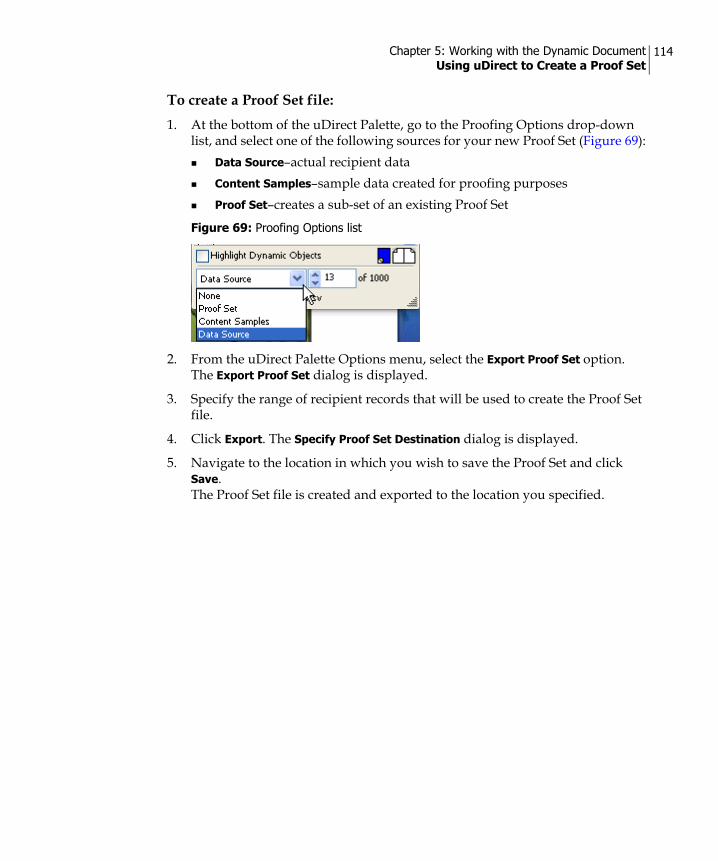
Chapter 5: Working with the Dynamic Document Using uDirect to Create a Proof Set
114
To create a Proof Set file: 1. At the bottom of the uDirect Palette, go to the Proofing Options drop-down
list, and select one of the following sources for your new Proof Set (Figure 69):Data Source–actual recipient dataContent Samples–sample data created for proofing purposes Proof Set–creates a sub-set of an existing Proof Set
2. From the uDirect Palette Options menu, select the Export Proof Set option. The Export Proof Set dialog is displayed.
3. Specify the range of recipient records that will be used to create the Proof Set file.
4. Click Export. The Specify Proof Set Destination dialog is displayed.
5. Navigate to the location in which you wish to save the Proof Set and click Save. The Proof Set file is created and exported to the location you specified.
Figure 69: Proofing Options list

Chapter 5: Working with the Dynamic Document Using Values from a Proof Set
115
Using Values from a Proof SetYou can use uDirect to open a Proof Set created using XMPie products. The Proof Set allows you to view the set of data values calculated for each recipient, as they are positioned in your design file. The Content Objects of your document will be replaced with the actual data and values for each recipient, as contained in the Proof Set.
To view your document with Proof Set values:1. Select Proof Set from the drop-down list at the bottom of the uDirect Palette,
and then click the icon to select the Proof Set file (*.proof, *.ppkg). The Select a Proof Set file dialog opens.
2. Locate and select the Proof Set that corresponds to the Content Objects currently defined in your document, and click the Open button. The Record scrolling box is displayed in bottom area of the Palette.
3. Use the arrows to choose the record you want to preview in the design application. The Dynamic Objects in the design are replaced with the values from the Proof Set.
4. Clear the Highlight Dynamic Objects option to view a copy of the design, as it will appear after composition.
Note: While linked to a Proof Set, if you create new Content Objects, delete Content Objects, or change the type of Content Objects, your Proof Set will be incompatible with these changes. To avoid inconsistencies, you will be unlinked from the Proof Set.
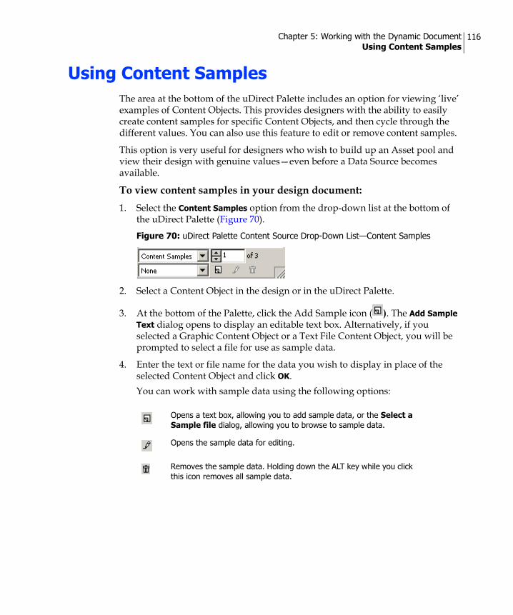
Chapter 5: Working with the Dynamic Document Using Content Samples
116
Using Content SamplesThe area at the bottom of the uDirect Palette includes an option for viewing ‘live’ examples of Content Objects. This provides designers with the ability to easily create content samples for specific Content Objects, and then cycle through the different values. You can also use this feature to edit or remove content samples.
This option is very useful for designers who wish to build up an Asset pool and view their design with genuine values—even before a Data Source becomes available.
To view content samples in your design document:1. Select the Content Samples option from the drop-down list at the bottom of
the uDirect Palette (Figure 70).
2. Select a Content Object in the design or in the uDirect Palette.
3. At the bottom of the Palette, click the Add Sample icon ( ). The Add Sample Text dialog opens to display an editable text box. Alternatively, if you selected a Graphic Content Object or a Text File Content Object, you will be prompted to select a file for use as sample data.
4. Enter the text or file name for the data you wish to display in place of the selected Content Object and click OK. You can work with sample data using the following options:
Figure 70: uDirect Palette Content Source Drop-Down List—Content Samples
Opens a text box, allowing you to add sample data, or the Select a Sample file dialog, allowing you to browse to sample data.
Opens the sample data for editing.
Removes the sample data. Holding down the ALT key while you click this icon removes all sample data.
Chapter 5: Working with the Dynamic Document Find the Shortest and Longest Values of a Text Content Object
117
Find the Shortest and Longest Values of a Text Content Object
uDirect allows you to find the shortest and longest values available for each Text Content Object in the selected Dynamic Content Source. This is a useful tool for planning the space required for the dynamic text in your Document. Once uDirect finds the record with the longest or shortest value, it displays this record’s values in the Document. You can then adjust the relevant text box so that it properly displays both short and long values.
To find the longest or shortest value of a Text Content Object:1. In the uDirect Palette, right-click a Text Content Object (in this case,
Address 1).
2. From the context menu, select Go to Shortest “Address 1” or Go to Longest “Address 1”. A progress bar is displayed, indicating uDirect is scanning all records to find the one with the shortest or longest value for this Text Content Object.Once the record is found, its values are displayed in the Document.
You can now go to the relevant text box and check how it displays the short or long value.
Figure 71 on page 118 shows an example search and its results: After searching for the longest value available for the Address 1 Text Content Object, the Document displays the values of record 15. This record’s value for Address 1 is 222 St. Augustin Rd.
Note: This feature applies to all types of Dynamic Content sources: Data Sources, Proof Sets and Content Samples.

Chapter 5: Working with the Dynamic Document Setting the Location of Assets
118
Setting the Location of AssetsuDirect searches for the Assets listed in your Data Source file, and uses their values to replace Content Objects during proofing and production. By default, uDirect assumes that all Assets reside in the same folder as the Data Source file currently linked to your document, or in its sub-folders. If you wish to set up a separate location for all your Assets, you can use the Set Assets Folder option to specify this location to uDirect.
Assets specified in the Data Source file may not necessarily include a file extension or data path. In these cases, uDirect uses the following unique search algorithm.
• For text or text file Assets, uDirect will search for a matching file name with the following extensions (in the order listed here):
*.txt (plain text) *.rtf (Rich text Format)
Figure 71: Go to Longest “Address1”
Note: If a specific record has no data for the selected Text Content Object, it will be used as the Shortest value, and the search results will show a blank entry.

Chapter 5: Working with the Dynamic Document Setting the Location of Assets
119
*.doc (MS Word)
• For graphic Assets, uDirect will search for a matching file name with the following extensions (in the order listed here):
*.eps/*.ps (PostScript)*.pdf (Portable Document Format) *.psd (Adobe Photoshop)*.tiff image *.bmp image *. jpeg image *. png image *. gif image
Using the Set Assets Folder OptionThe Set Assets Folder option allows you to specify a folder that contains the required Assets for printing or proofing the Dynamic Document with Data Source, Proof Set, or content sample data. The folder should be specified for each linked Data Source, content sample, or Proof Set you select.
For example, if your Data Source refers to graphic images called bouquetrose.jpg, bouquetlilly.jpg, bouquetdaisy.jpg… that reside in a folder called ‘Images’ (which does not reside in the same folder as your Data Source), you should specify the location of this folder using the Set Assets Folder option. This will enable uDirect to search the folder, and sub-folders, for the referenced images when you proof or print your document with data.
The same is true for Proof Sets, when the Document is linked to a Plan instead of a Data Source. In this case, the Proof Set might refer to image files that do not reside in the same folder as your Proof Set. Therefore, you should specify the location of this folder using the Set Assets Folder option.
To set a folder for Assets:1. From the uDirect Options menu, select the Set Assets Folder option.
The Browse for Folder dialog is displayed.
2. Select the desired folder and click OK to close the dialog. uDirect now uses the Assets from the specified folder when displaying the sample data for proofing.
Note: If you do not specify a particular folder for the location of your Assets, uDirect will automatically search in the folder that contains your Data Source file, and in its sub-folders.

Chapter 5: Working with the Dynamic Document Using XMPie Exchange Packages
120
Using XMPie Exchange PackagesAlthough uDirect is self-contained and can serve you fully from design to production, if you occasionally require additional capabilities, you may achieve these through collaboration with a print server provider who owns the XMPie PersonalEffect software.
For more details on the collaboration workflow, see Chapter 7: Collaborating with other uDirect or uProduce Users on page 141.
After designing the document, you can export it to a Document package, a XLIM package or a XLIM file, and then upload it to the uProduce server for the final production of the print file. Use the XLIM solution to increase the production speed of straightforward designs on the uProduce server.
A document or XLIM package is saved with a *.dpkg extension, and includes the Dynamic Document, all the information pertaining to it, and its related Resources. A XLIM file is saved with the *.xlim extension and includes the Dynamic Document alone (without its related information and Resources).
Being able to send a print service provider your Dynamic Document —and not just the print-ready output file for a specific run—opens the door for many useful collaboration scenarios. For example, you may want your print provider to be able to do some print-specific last minute changes to a design (for example, fit to some folding constraints). In all such cases, you can leverage the uDirect ability to export and import Document packages to make the workflow straightforward and streamlined. These packages are referred to as Campaign packages and Document packages:
• Document package—using the *.dpkg file extension. This file includes the design document (within which are stored the Content Objects, and the associations, or bindings, of Content Objects to Design Objects), along with all related Resources.
• Campaign package—using the *.cpkg file extension. This file includes the design Document package, along with your Data Source file, rules, and all related Assets and fonts (Campaign fonts are stored in ‘Fonts’ directory). This file can be uploaded to the XMPie uProduce server and used to build a Campaign for the production of the final customer communication.
Note: Mac OS and Windows platforms use different font systems. As a result, only unpacked Open Type fonts are supported on both platforms. Furthermore, the list of fonts for packing is based on the design template, meaning fonts that are used in dynamic content will not be stored in the Campaign file.

Chapter 5: Working with the Dynamic Document Using XMPie Exchange Packages
121
To export the document to a package for use with uProduce or another uDirect:1. Save the document in the design application.
2. From the uDirect Options menu, select the XMPie Exchange Export option. The Save As dialog is displayed.
3. Search for a location in which to save the packaged document and select the type of file you wish to save. Select Campaign Package Files (*.cpkg) for export to uProduce and Document Package Files (*.dpkg) for export to either uProduce or another uDirect.
4. Click Save. The package file is created and stored in the location you specified.
To import the document from a package:1. From the uDirect Options menu, select the XMPie Exchange Import option.
The Select Document Package dialog box is displayed.
2. Click Unpack to save the unpacked files to the default location and open the document file in InDesign. Alternatively, click Browse, search for a location in which to save the unpacked files, and click Save.
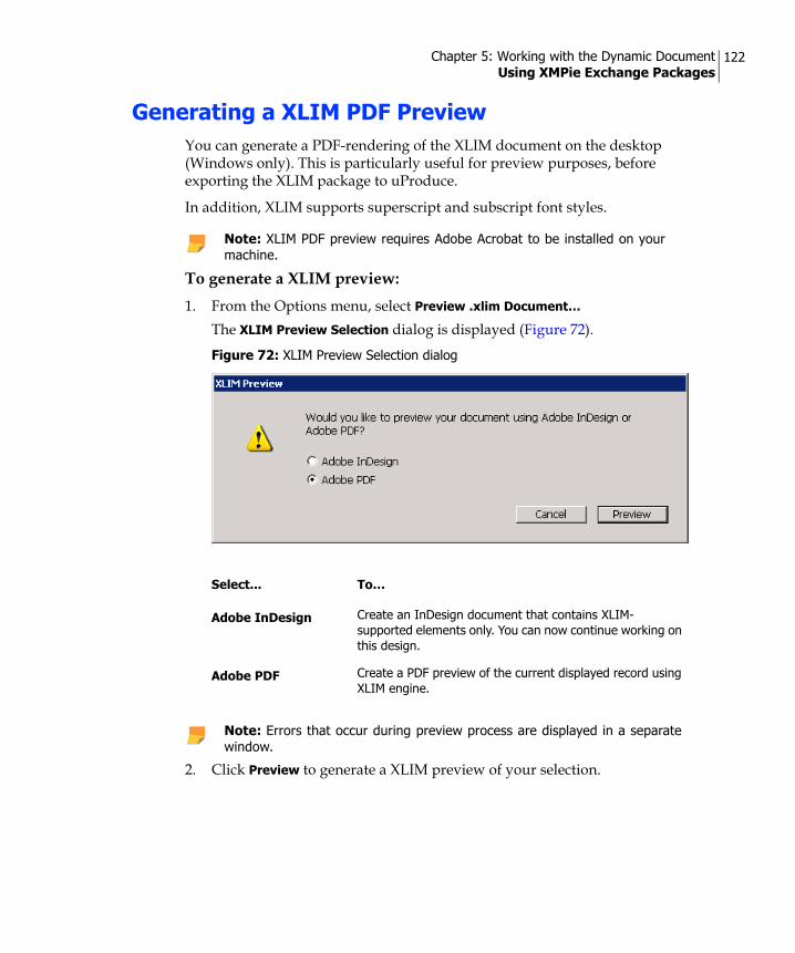
Chapter 5: Working with the Dynamic Document Using XMPie Exchange Packages
122
Generating a XLIM PDF PreviewYou can generate a PDF-rendering of the XLIM document on the desktop (Windows only). This is particularly useful for preview purposes, before exporting the XLIM package to uProduce.
In addition, XLIM supports superscript and subscript font styles.
To generate a XLIM preview:1. From the Options menu, select Preview .xlim Document…
The XLIM Preview Selection dialog is displayed (Figure 72).
2. Click Preview to generate a XLIM preview of your selection.
Note: XLIM PDF preview requires Adobe Acrobat to be installed on your machine.
Figure 72: XLIM Preview Selection dialog
Select... To…
Adobe InDesign Create an InDesign document that contains XLIM-supported elements only. You can now continue working on this design.
Adobe PDF Create a PDF preview of the current displayed record using XLIM engine.
Note: Errors that occur during preview process are displayed in a separate window.
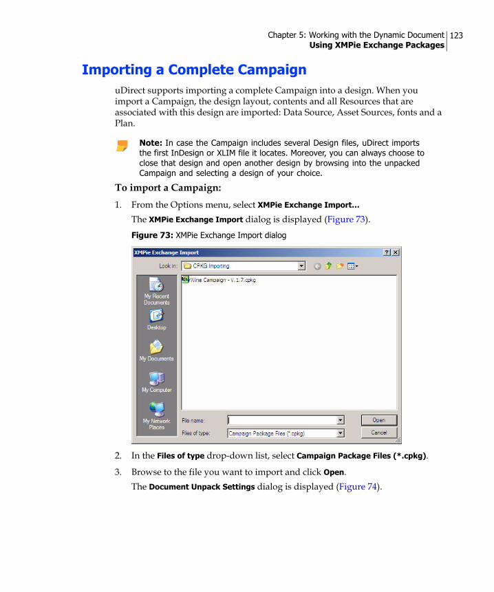
Chapter 5: Working with the Dynamic Document Using XMPie Exchange Packages
123
Importing a Complete CampaignuDirect supports importing a complete Campaign into a design. When you import a Campaign, the design layout, contents and all Resources that are associated with this design are imported: Data Source, Asset Sources, fonts and a Plan.
To import a Campaign:1. From the Options menu, select XMPie Exchange Import…
The XMPie Exchange Import dialog is displayed (Figure 73).
2. In the Files of type drop-down list, select Campaign Package Files (*.cpkg).
3. Browse to the file you want to import and click Open. The Document Unpack Settings dialog is displayed (Figure 74).
Note: In case the Campaign includes several Design files, uDirect imports the first InDesign or XLIM file it locates. Moreover, you can always choose to close that design and open another design by browsing into the unpacked Campaign and selecting a design of your choice.
Figure 73: XMPie Exchange Import dialog

Chapter 5: Working with the Dynamic Document Using XMPie Exchange Packages
124
Importing Formatted Text into a DesignFormatted Text support has been expanded, in terms of both the available formats and the types of Content Objects used to import these formats.
XNIP (*.xnip) File Format
A XNIP (*.xnip) file may be used as text file Content Object value in XMPie Campaigns. It uses the XMPie’s proprietary, XML-based XLIM file format (*.xlim) to convey rich text. Its main advantage in comparison to other rich text formats is that it supports the inclusion of images. XNIP is only supported as part of the InDesign composition, and not as part of the XLIM file composition.
XNIP files are easily created, by marking the desired formatted text snippets in your design, and saving them in *.xnip format. You can then use a XNIP file in a number of ways:
• Insert the XNIP file directly into your document.
• Use the XNIP file as an Asset that is referenced by a Text File Content Object.
• Insert the XNIP file into a database field that is referenced by a Text Content Object.
Figure 74: Document Unpack Settings dialog
Click… To…
Unpack Unpack the Campaign into the same directory, in which the CPKG file is stored.
Browse… Select a directory of your choice, in which you want to unpack the Campaign.
Cancel Abort the import operation.

Chapter 5: Working with the Dynamic Document Using XMPie Exchange Packages
125
To create XNIP files:1. Mark the formatted text you wish to save as a text snippet.
2. Right click the selected text, and select Save as XNIP Formatted Text… from the context menu.The Save As dialog is displayed, with the File name drop-down list set by default to the current document’s name, followed by the *.xnip suffix (Figure 75 on page 125).
3. Rename the text snippet as needed.
4. Browse to the desired location in your file system and click Save.
Figure 75: Saving a Text Snippet as a XNIP File (*.xnip)

Chapter 5: Working with the Dynamic Document Using XMPie Exchange Packages
126
To use XNIP files in your document:1. Choose one of the following:
To insert a XNIP file into a text frame, right-click the desired location within the text frame, and select Insert XNIP Formatted Text… from the context menu.To use a XNIP file instead of Text Content Object or a Text File Content Object, select the Content Object’s place holder, right-click and select Replace with XNIP Formatted Text… from the context menu.
The Open a File dialog is displayed, with the Files of type drop-down list set to XMPie XLIM Snippet Format (Figure 76 on page 126).
2. Browse to the relevant *.xnip file, select it and click Open.The XNIP File is inserted into the desired location in your document.
Figure 76: Using XNIP files in your Document

Chapter 5: Working with the Dynamic Document Using XMPie Exchange Packages
127
Importing Formatted Text using Content ObjectsYou can import formatted text not only from external files (that is, Assets), using Text File Content Objects; but also from the data stream (that is, from the Logic or from the Data), using Text Content Objects.
• Text File Content Objects can now import the new XNIP file format, in addition to the previously-supported formats:
Plain Text (*.txt)InDesign Tagged Text (*.txt)Rich Text Files (*.rtf)Microsoft Word Documents (*.doc)
• Text Content Objects can now import formatted text, in addition to the previously-supported Plain Text (*.txt). The newly supported formats include:
InDesign Tagged Text (*.txt)Rich Text Files (*.rtf)XNIP (*.xnip)

Chapter 6
Printing the Dynamic DocumentuDirect enables you to generate an output file for printing all document instances that will result from a given Data Source. Your output file format can be any one of the leading, industry-standard VDP formats; this serves to ensure efficient processing at print time.
The Dynamic Print option is available provided that your document is already linked to a Data Source, a Proof Set file, or if you are using content samples.
InDesign Dynamic Documents, which have Content Object values assigned to them, are processed using the Dynamic Print option, described in the following section.
Creating a Print File of a Dynamic DocumentThe Dynamic Print option allows you to create a print file that contains personalized instances of your InDesign Dynamic Document. This print file is generated using values from your linked Data Source, Proof Set file, or content samples.
To print the InDesign Dynamic Document, with Data Source values:1. Open the document you wish to print.
2. Click the button at the top of the uDirect Palette, and select the Dynamic Print option.The Dynamic Print dialog is displayed (Figure 77 on page 129).
Note: uDirect can interact with Adobe Acrobat on Windows or Mac OS to create a highly optimized PDF output. In case Adobe Acrobat is not installed, uDirect will create regular PDF files.

Chapter 6: Printing the Dynamic Document Creating a Print File of a Dynamic Document
129
This dialog consists of a static, Common Dynamic Print Properties, a list of views; and a view-specific pane that changes as a function of any of the following views you select from the list:
• Policies View
• Copies View
• Step & Repeat View
• Advanced View
Figure 77: Dynamic Print dialog—Policies View

Chapter 6: Printing the Dynamic Document Creating a Print File of a Dynamic Document
130
Common Dynamic Print Properties The common pane of the Dynamic Print dialog (shown on the previous page) allows you to define the following fields and options:
Note: The VI format(s) you have selected determine(s) the options available in the Dynamic Print dialog. The examples in this section show options enabled by the PPML/PS VI format.
Data Source Select the Data Source that includes the recipient information, from which you wish to generate the print file.
Format Format in which to print the files. From the drop-down list, select the desired format. Select the Compress Output (ZIP) check box if you want to compress the output file to a ZIP file. This is useful when expecting a production output of large files or when the output files are to be packed into a single file.
Records You can either define a range of records you wish to print or select to print all records.
Destination The folder in which to create the resulting print file. Click Browse to locate the full path to the folder.By default, the print file is saved in the output folder next to the InDesign document (within a folder named using the current date and time).

Chapter 6: Printing the Dynamic Document Creating a Print File of a Dynamic Document
131
Policies ViewThis is the default view displayed when you open the Dynamic Print dialog (Figure 77 on page 129). Use this view to specify how to define your policies for handling different types of errors that might occur during production.
Window Item Description
On Missing AssetOn Missing FontOn Missing StylesOn Text Overflow
Specifies the manner in which you want to handle missing items or inconsistencies. For cases of Missing Assets, Missing Fonts, Missing Styles or Text Overflow, use the drop-down list to indicate how to handle the error. Choose one of the following options:Ignore—to process this record in spite of the error. The output file will include this erroneous customer communication. Fail job—to stop processing this job altogether for all recipients. No output file will be generated.Skip Record (missing Assets and styles only)—to move on to process the next record. The output file will not include data for this record.
On X-DOT Required
You can select the way X-DOT is implemented in your document or you can choose not to use X-DOT. Available options are:• Use X-DOT—use the X-DOT technology.• Ignore X-DOT as needed—do not apply X-DOT in this production
run in the following cases:The resulting mega object is reusable and at least one of the atomic objects is fixed. -Or-The resulting mega object is unique and at least one of the atomic objects is reusable or is fixed. -Or-The resulting mega object is reusable and contains more than one atomic object that is reusable. Ignoring X-DOT results in:Special affects will not be visible. All shadows, feathering and opacity effects will be removed.For transparent images, their transparent parts will appear white (paper color).
• Ignore X-DOT—no special effects will appear in the Print Output file of this production run. Note that this is equivalent to using the InDesign feature 'Ignore Flattening' in all of the document’s spreads.
• Fail job—fail the current production run in each of the cases that affect the Ignore X-DOT as needed option (see above).
More on X-DOT technology can be found in Using XMPie Dynamic Object Transparency (X-DOT) Technology on page 105.

Chapter 6: Printing the Dynamic Document Creating a Print File of a Dynamic Document
132
Copies ViewThis view determines the number of copies that are to be printed per recipient record (Figure 78).
Step & Repeat ViewThis view enables you to optimize the press sheet surface, by having several different pages on the surface of one printed sheet. This feature is often used for double-sided planning, labels, postcards, and packaging printers (Figure 79).
Figure 78: Dynamic Print dialog—Copies View
Window Item Description
Copies Enter the number of personalized document instances you wish to create for each recipient.
Based on the value of If the above number of Copies is based on the value of a specific Content Object, choose this object from the drop-down list.
Figure 79: Dynamic Print dialog—Step & Repeat View

Chapter 6: Printing the Dynamic Document Creating a Print File of a Dynamic Document
133
Window Item Description
Enable Step & Repeat Select this check box to enable Step & Repeat for your print job. Note that all measurement values are in points. You can change the measurement units via the InDesign Preferences (from the InDesign menu, choose Edit > Preferences > Units and Increments...).
Sheet Size Select a standard sheet size (for example, Letter, A4, etc.) from the drop-down list, to determine Sheet Dimensions.Alternatively, enter your custom Sheet Dimensions.
Sheet Dimensions Enter the Width and Height of the custom physical sheet being used for printing.
Page Dimensions Width and Height of the logical design page. These values are used to calculate the number of pages that can fit on a sheet.
Margin Enter the Width and Height of the margins to be maintained between the edges of the logical pages and the edges of the sheet.
Gap Enter the X and Y values to set the gap that will be maintained between the logical pages on the sheet.
Auto Calculate Automatically calculates how many pages fit into a sheet.
Pages on Sheets Manually enter the number of logical pages (Columns and Rows) that can fit on each sheet.
Cut and Stack Select this check box to order the pages on the sheet as follows: front-back, left-right, top-bottom. If you do not select this option, uDirect uses the default order: left-right, top-bottom, front-back.
Duplex Select this check box to order even sheets, so the front side and backside will match for each recipient (flip horizontally).
Center Page on Sheet Select this check box to center all the pages that will be printed on the sheet. If you do not select this option, uDirect will set out the pages starting from the bottom-left corner of the sheet.
Draw Page Info Select this check box to add the page information above each logical design page. This information includes the recipient number, and the page number of this recipient. This information is printed in the Gap/Margin area.
Draw Cut Marks (X, Y)
Adds cutting (crop) marks on the margin area of the sheet. Select this check box to add crop marks, and then set their inset value in the Bleed X and Bleed Y fields. Note that Cut Marks require room to draw within the Margin area (not next to the document). If you add Cut Marks, be sure to set the Margin Height and Width fields to greater than or equal to nine points.

Chapter 6: Printing the Dynamic Document Creating a Print File of a Dynamic Document
134
Advanced ViewThis view enables you to set advanced print parameters, used mainly to determine the specific variant of your output format, to suit the workflow and the specific print controller you are using (Figure 80).
Figure 80: Dynamic Print dialog—Advanced View
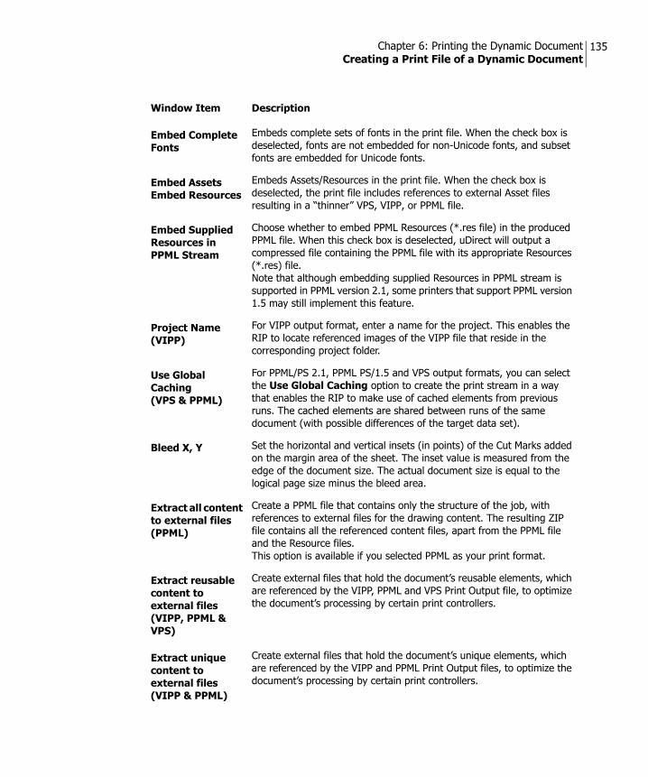
Chapter 6: Printing the Dynamic Document Creating a Print File of a Dynamic Document
135
Window Item Description
Embed Complete Fonts
Embeds complete sets of fonts in the print file. When the check box is deselected, fonts are not embedded for non-Unicode fonts, and subset fonts are embedded for Unicode fonts.
Embed Assets Embed Resources
Embeds Assets/Resources in the print file. When the check box is deselected, the print file includes references to external Asset files resulting in a “thinner” VPS, VIPP, or PPML file.
Embed Supplied Resources in PPML Stream
Choose whether to embed PPML Resources (*.res file) in the produced PPML file. When this check box is deselected, uDirect will output a compressed file containing the PPML file with its appropriate Resources (*.res) file.Note that although embedding supplied Resources in PPML stream is supported in PPML version 2.1, some printers that support PPML version 1.5 may still implement this feature.
Project Name (VIPP)
For VIPP output format, enter a name for the project. This enables the RIP to locate referenced images of the VIPP file that reside in the corresponding project folder.
Use Global Caching(VPS & PPML)
For PPML/PS 2.1, PPML PS/1.5 and VPS output formats, you can select the Use Global Caching option to create the print stream in a way that enables the RIP to make use of cached elements from previous runs. The cached elements are shared between runs of the same document (with possible differences of the target data set).
Bleed X, Y Set the horizontal and vertical insets (in points) of the Cut Marks added on the margin area of the sheet. The inset value is measured from the edge of the document size. The actual document size is equal to the logical page size minus the bleed area.
Extract all content to external files (PPML)
Create a PPML file that contains only the structure of the job, with references to external files for the drawing content. The resulting ZIP file contains all the referenced content files, apart from the PPML file and the Resource files.This option is available if you selected PPML as your print format.
Extract reusable content to external files (VIPP, PPML & VPS)
Create external files that hold the document’s reusable elements, which are referenced by the VIPP, PPML and VPS Print Output file, to optimize the document’s processing by certain print controllers.
Extract unique content to external files (VIPP & PPML)
Create external files that hold the document’s unique elements, which are referenced by the VIPP and PPML Print Output files, to optimize the document’s processing by certain print controllers.

Chapter 6: Printing the Dynamic Document Creating a Print File of a Dynamic Document
136
Add metadata to each record (PPML)
Add recipient’s Content Object values to the output file to enable management features on certain print controllers.
Tag each record as a document group (PPML)
Determine the way to mark a document set (in PPML version 2.1) or a job (in PPML version 1.5) in the PPML file:When selected, each record in the collection of documents is tagged as a document set/job.When deselected, the entire collection of documents in the PPML file is tagged as a single document set/job.
Tag fixed background as a master page (PPML & VDX)
Mark a background that is used for all records in a way that enables certain print controllers to process the print file more efficiently.Note that if the document contains one or more Spread Visibility rules, no tagging as master page is performed.
Window Item Description

Chapter 6: Printing the Dynamic Document Using Media Selection for Printing
137
Using Media Selection for PrintingThe Dynamic Media Selection option enables you to define a string or Content Object associated with a spread. This string is used to tell the print controller the specific media on which the spread is to be printed.
For example, you may be printing a booklet that uses heavyweight blue paper for the cover page, regular white paper for the body pages, and red paper for section dividers between the chapters of the book. In this case, you could use Dynamic Media Selection to assign different media, stored in different paper trays, to improve production control and the overall workflow. When the job is processed, the assigned paper will be automatically selected from the appropriate paper tray.
To set up media selection for a spread:1. On Pages Palette, select a spread and then select Dynamic Media Selection
from the Palette menu. Alternatively, you can right-click anywhere in the spread for which you are setting media selection (where no item exists), and select Dynamic Media Selection from the context menu. The Dynamic Media Selection dialog is displayed (Figure 81).
2. Select the desired option and specify the Content Object or string to be mapped to the media on the print controller, as follows:
3. Click OK to save your changes and close the dialog.
Figure 81: Dynamic Media Selection
Window Item Description
Same as previous The spread should be printed on the same media as the previous spread. NOTE: Do not use this option for the first spread in your document.
Based on the value of
For each record, the spread’s media will be set by the Content Object value you select here.
(Enter string) Enter the string that is mapped at the print controller to the media required for the spread.

Chapter 6: Printing the Dynamic Document Controlling Adobe PDF Settings
138
Controlling Adobe PDF SettingsuDirect print production uses the Adobe Normalizer library to create PDF output files, eliminating the need to install the Adobe Acrobat distiller for PDF output file creation. You can control the Adobe PDF settings within Adobe InDesign to improve and optimize your PDF output.
To control Adobe PDF Settings:1. From the Adobe InDesign File menu, select Adobe PDF Presets, and then select
Define.The Adobe PDF Presets dialog is displayed (Figure 82).
2. Select the required XMPie Preset from the Presets list and click Edit. The Edit PDF Export Preset dialog is displayed (Figure 83).
Figure 82: Adobe PDF Presets

Chapter 6: Printing the Dynamic Document Controlling Adobe PDF Settings
139
3. Make any required changes to the setting and click OK.
The settings files are taken by default from the application data folder: C:\Documents and Settings\[USERNAME]\Application Data\Adobe\Adobe PDF\Settings folder, and should be saved back into this folder once the changes to the settings have been made. If the Application Data folder does not exist then the [XMPie Plugins Folder]\ProdResources folder should used.
Figure 83: Edit PDF Export Presets

Chapter 6: Printing the Dynamic Document Controlling Adobe PDF Settings
140
To save the PDF settings:1. In the Edit PDF Export Presets dialog (Figure 83 on page 139), click Save As.
The Save PDF Export Presets dialog is displayed (Figure 84).
2. Select the C:\Documents and Settings\[USERNAME]\Application Data\Adobe\Adobe PDF\Settings folder, or [XMPie Plugins Folder]\ProdResources, and click Save.
Figure 84: Save PDF Export Preset

Chapter 7
Collaborating with other uDirect or uProduce Users
Although uDirect is self-contained, you may want to collaborate with other uDirect users or with PersonalEffect users who are using uProduce to provide print or cross-media services (for example, print service providers).
Collaborating with other uDirect users can be easily achieved by sharing the InDesign file (which encodes all the uDirect specific information), or by exporting and importing of Document packages. For more details, see Using XMPie Exchange Packages on page 120.
Collaborating with a Print Service Provider (PSP) can be accomplished in several ways, from simply sending print ready files generated by uDirect to exchanging Campaign or Document packages between the uDirect user and a PSP that has a uProduce server.
As noted earlier in this guide, uDirect can be used to generate print-ready streams (files). These files can be delivered to a print provider for production printing. Although this is a perfectly valid and feasible workflow, it has certain limitations. First, there is very little room for last minute adjustments by the PSP. Second, the creative professional must be involved with every production detail and they must be available whenever needed for making even small last minute changes. The PSP becomes a simple print engine hosting entity, with very little room for adding value.
If your PSP has uProduce, you can interact with them via Campaign packages or Document packages. These packages allow creative professionals to deliver uDirect jobs to a PSP and let the PSP continue working with the job, as an XMPie Campaign. In such a scenario, the PSP can use the uProduce server and accompanying uPlan and uDirect modules to make last minute changes as needed, possibly connect to a Data Source other than the one used by the creative professional, or, if needed, take the uDirect generated Campaign into cross-media.

Chapter 7: Collaborating with other uDirect or uProduce Users Collaborating with other uDirect Users
142
These package-based workflow scenarios are similar to application-file based workflow scenarios that are common in (static) publishing. In such classical workflow scenarios, a creative professional and a PSP will collaborate based on exchanging InDesign files, and not just the PostScript or PDF files for the final print run. Both creative professionals and PSPs appreciate the benefits of enabling the PSP to carry out last-minute changes. These benefits, as well as others – such as connecting to a different Data Source, adding more sophisticated rules, adding cross-media, and much more robust production control – are the key reasons for having package-based workflows.
Collaborating with other uDirect UsersThere are three collaboration workflow scenarios for two or more uDirect users:
• Exchanging uDirect InDesign files
• Exchanging Document packages files
• Exchanging Proof Set files
Exchanging uDirect InDesign files is very simple, and it is similar to any scenario where people collaborate based on exchanging application files.
As in all such scenarios, all collaborating users must have access to all required Resources (such as fonts, graphics, data and Assets).
Exchanging Document Package files is another means of collaboration, where the importing side may not have access to the Data Source or rules.
In a way, by exporting a Document package, the user that created the job gives another user (the one importing the job) access to a replica of the design, the list of Content Objects, and their links. Importing a Document package is an excellent way to get another uDirect user started on the project. They have immediate access to the current design, the list of Content Objects, and the association between these and design objects.
Exchanging Proof Set files is a way to collaborate, without replicating data-source access or even the specification of rules.
The uDirect user who specified the rules and has access to a Data Source, can export a Proof Set that can be imported by another user; one who may not have access to the Data Source or the rules defined by the first user. The importing user can, in this way, view the design document with the various sample data points given in the Proof Set.

Chapter 7: Collaborating with other uDirect or uProduce Users Collaborating with uProduce users
143
Collaborating with uProduce usersThere are three collaborating workflow scenarios for uDirect and uProduce users:
• Upload a Campaign package from uDirect to uProduce
• Upload and download Document package files between uDirect and uProduce
• Importing a Proof Set generated by uProduce
Upload a Campaign package from uDirect to uProduce. The uDirect user packs the job (Design, Data, Assets, and Rules) in a Campaign package file. This file allows the uProduce user to automatically create an XMPie Campaign–including Plan, design, data, and Assets connections– from the work done by the uDirect user.
Once a Campaign had been created in uProduce it can be leveraged for more sophisticated Data Source connections or rules, last minute production-oriented design changes, or adding HTML documents for cross-media. In addition, and no less important, is the ability of the uProduce user to harness more powerful production flows, including employing concurrency in job processing.
Uploading a Campaign package file to a Print Service Provider (PSP) that has uProduce is the ideal workflow for moving jobs from creative to production.
The capabilities of the rules language and database connectivity available with uProduce far exceed those provided in uDirect. As a result, the Campaign package process is one way– from uDirect to uProduce. There is no way for uDirect to import a Campaign package that was created in uProduce, as it will contain elements not known to uDirect.
Upload and download Document package files between uDirect and uProduce. A Document package is ideal for cases where a uDirect user does not need to upload Data Sources or rules, but only the design, Content Objects list, and the association between these two.
Similarly, if a uProduce user would like a uDirect user to review changes to a design, a Document package can be created by the uProduce user and imported by the uDirect user. If the uDirect user makes further changes to the design then a new Document package can be created and uploaded to the uProduce server.
Importing a Proof Set generated by uProduce. A uDirect user who created the first draft of a Campaign may want to see how the project looks with the most recent design modifications and the most recent set of data and Assets sources. By linking to a Proof Set file generated by uProduce, the uDirect user can view the results of the most recent changes in data or rules.

Chapter 7: Collaborating with other uDirect or uProduce Users Exchange Scenarios Summary
144
Exchange Scenarios SummaryThe following table summarizes the file formats that can be shared with uDirect.
Note: Within the XMPie environment, Content Objects are sometimes referred to as ADOR Objects.
File Type Created By Can Be Used By
Campaign Package uDirect, uProduce uDirect, uProduce
Document Package uDirect, uProduce uDirect, uProduce
Proof Set File uDirect, uProduce uDirect
Proof Set Package uPlan, uProduce uDirect
Note: To be able to link to either a Data Source or a Plan file (that is, to work in dual mode), you must have a uDirect professional license.
Appendix A
Rule Editor ExpressionsThe Content Object Rule Editor (Rule Editor, in short) enables you to create or edit Content Objects definitions, by defining expressions that perform conversions and manipulations on the Data Source values. These expressions are defined using XMPie’s proprietary QLingo language.
All expressions can be defined manually as QLingo code, by clicking the Rule Editor’s View QLingo... button and editing the Content Object’s QLingo Rule. In addition, the most commonly-used expressions are available for selection directly from the Rule Editor’s drop-down lists.
This chapter provides a detailed description of the available expressions.
QLingo LanguageQLingo is a scripting language developed by XMPie, to define expressions that compute Content Objects values.
QLingo language includes the following types of expressions:
• Literal Constants (see page 146)
• Arithmetic Expressions (see page 149)
• Comparisons (see page page 150)
• Logical Expressions (see page 150)
• Control Statements (see page 151)
• Functions (see page 153)
• Recipient Information Field Reference (see page 187)
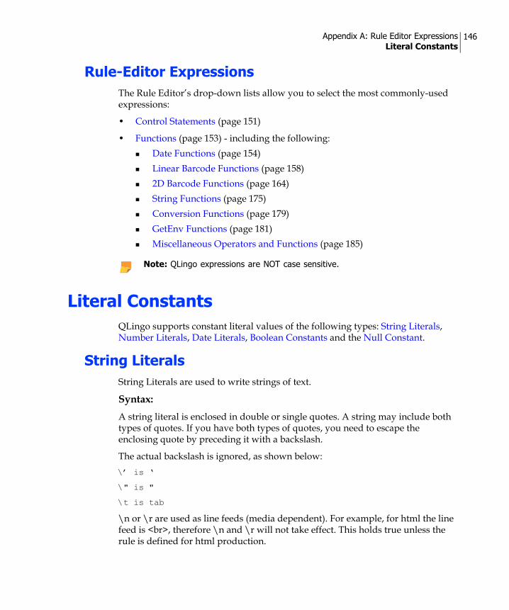
Appendix A: Rule Editor Expressions Literal Constants
146
Rule-Editor ExpressionsThe Rule Editor’s drop-down lists allow you to select the most commonly-used expressions:
• Control Statements (page 151)
• Functions (page 153) - including the following:Date Functions (page 154)Linear Barcode Functions (page 158)2D Barcode Functions (page 164)String Functions (page 175)Conversion Functions (page 179)GetEnv Functions (page 181)Miscellaneous Operators and Functions (page 185)
Literal ConstantsQLingo supports constant literal values of the following types: String Literals, Number Literals, Date Literals, Boolean Constants and the Null Constant.
String LiteralsString Literals are used to write strings of text.
Syntax:A string literal is enclosed in double or single quotes. A string may include both types of quotes. If you have both types of quotes, you need to escape the enclosing quote by preceding it with a backslash.
The actual backslash is ignored, as shown below:\’ is ‘
\" is "
\t is tab
\n or \r are used as line feeds (media dependent). For example, for html the line feed is <br>, therefore \n and \r will not take effect. This holds true unless the rule is defined for html production.
Note: QLingo expressions are NOT case sensitive.

Appendix A: Rule Editor Expressions Literal Constants
147
\\ is \
\b is b, and so on
Examples:The following examples show the escape sequence in the strings."Joan’s Car"—Joan’s Car
‘Joan\’s Car’—Joan’s Car
‘\Joan’—Joan
"Joan\nSmith"—Joan Smith
"Joan\tSmith"—JoanSmith
"text starts with \"Hello …\""—text starts with "Hello …"
‘text starts with "Hello …"’—text starts with "Hello …"
"\\Joan\\" - \Joan\
Number LiteralsNumber literals are used to write text that includes numbers.
Syntax:A number literal can be optionally preceded by a positive or negative sign and can include a decimal point.
Examples:123
+201
-2
1.34
-1898.22214
Date LiteralsDate literals are used to include dates according to specified formats.
Syntax:A date literal is enclosed in pound signs (#). The currently supported date formats are dd/mm/yyyy and dd/mm/yy. You can use QLingo’s ‘FormatDate’ function to format dates in a different way.

Appendix A: Rule Editor Expressions Literal Constants
148
The use of the following delimiters is also supported: ‘\’, ‘/’, ‘-‘ and ‘.’.
Single digit numbers must have a preceding zero.
Examples:#02/03/2001#
#14\06\92#
#02-03-2001#
#14.06.92#
Boolean ConstantsBoolean constants can be used in logical expressions. There are two built-in logical constants: TRUE and FALSE.
Null ConstantNull is a built-in constant that represents the null value (the database concept of an undefined value).
Null also represents a non-existent value. For example, if a query returns one row, and references a value in a second row that does not exist, the result is null. Additionally, in the case where you have an If statement that does not contain ‘else', if the condition is not met, the expression value is Null.
Note that the Null value as an end result of an ADOR Object is treated as an empty string.
Syntax:Null constants can be used in comparisons with the Equality (==) or Non-Equality (!=) tests.
Examples:[MyRecordset][0].[Name] != NULL
@{startDate} == null

Appendix A: Rule Editor Expressions Arithmetic Expressions
149
Arithmetic ExpressionsQLingo currently supports several arithmetic operations with the conventional order of precedence.
The operations, in order of priority, are mod, div, *, /, +, -, and &.
Syntax:
Examples:Regular arithmetic:5 * 3 = 15
5 / 2 = 2.5
5 Div 2=2
5 Mod 2=1
Concatenation:"Joan" & " " & "Smith"=Joan Smith
56 & 4 = 564
#31/01/1973# & " Date"=31/01/1973 Date
The ‘+’ sign between strings as concatenation:
Use … To…
* , / , - , and + signs Perform arithmetic calculations
+ sign Concatenate strings. "a" + "b"
+ sign Add number of days to date. #31/01/73# + 31
- sign Subtract dates to receive the difference in number of days. #31/01/73# - #12/01/73# (= 19)
& sign Concatenate any type, while the result is a string. "a" & 1 (= "a1") , 1 & 2 (= "12")
Mod Perform modulo operations. 5 mod 2 = 1. Any fractional part of a number is lost. 5.1 mod 2 = 1
Div Conclude the round division answer. 5 div 2 = 2. Any fractional part of a number is lost. 5.1 div 2 = 2

Appendix A: Rule Editor Expressions Comparisons
150
"Joan" + " " + "Smith"-=Joan Smith
The ‘+’ and ‘-‘ signs between date and number to add/subtract days to/from a date:#01/01/2002# + 2=03/01/2002
#03/01/2002# - 2=01/01/2002
The ‘-‘ sign between dates in order to get the difference in number of days:#03/01/2002# - #01/01/2002#=2
ComparisonsYou can use comparisons in logical expressions.
Syntax:Comparisons use the general syntax of expression compOp expression.The compOp can be one of: <, <=, ==,=,<>,!=, >=, or >.
=,== are the same
!=,<> are the same
The comparisons have lower precedence than the arithmetic so writing 5 + 3 > 2 + 9 is equivalent to writing (5+3) > (2+9)
Logical ExpressionsLogical expressions allow you to define a number of conditions and to make comparisons.
Syntax:A logical expression is a logical constant, a comparison, or a logical expression made by using the logical operators: NOT,!, OR and AND.
Not and ! are the same
The logical expressions have lower precedence than the comparisons so writing 5 > 10 and 3 == 5 is the same as (5>10) and (3==5)
The logical expressions are evaluated in order. So when writing if((@{a} != NULL) AND (@{a} == @{b})), the first expression will be evaluated first, and only if it evaluates to "True" the second expression will be evaluated as well.
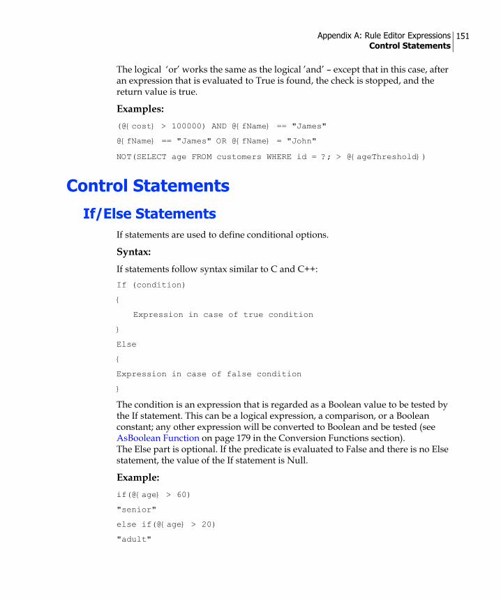
Appendix A: Rule Editor Expressions Control Statements
151
The logical ‘or’ works the same as the logical ’and’ – except that in this case, after an expression that is evaluated to True is found, the check is stopped, and the return value is true.
Examples:(@{cost} > 100000) AND @{fName} == "James"
@{fName} == "James" OR @{fName} = "John"
NOT(SELECT age FROM customers WHERE id = ?; > @{ageThreshold})
Control Statements
If/Else StatementsIf statements are used to define conditional options.
Syntax:If statements follow syntax similar to C and C++:If (condition)
{
Expression in case of true condition
}
Else
{
Expression in case of false condition
}
The condition is an expression that is regarded as a Boolean value to be tested by the If statement. This can be a logical expression, a comparison, or a Boolean constant; any other expression will be converted to Boolean and be tested (see AsBoolean Function on page 179 in the Conversion Functions section). The Else part is optional. If the predicate is evaluated to False and there is no Else statement, the value of the If statement is Null.
Example:if(@{age} > 60)
"senior"
else if(@{age} > 20)
"adult"

Appendix A: Rule Editor Expressions Control Statements
152
else
"young"
Switch StatementA switch statement is a simplified way to write a multi-choice ‘If’ statement.
Syntax:The switch statement uses the following syntax:Switch (expression)
{
Case literal1:
Expression1
Case literal2:
Expression2
Default:
DefExpression
}
The DEFAULT case is optional. If no case matches the expression and there is no default case, the value of the switch statement is Null.
Example:Switch (@{category})
{
Case "PLATINUM":
250000
Case "GOLD":
70000
Case "SILVER":
30000
Default:
10000
}

Appendix A: Rule Editor Expressions Functions
153
Functions
Numeric Functions
ABS Function
The ABS function gets the absolute value of the number expression.
Syntax:ABS(number expression)
Example:ABS(-5) = 5
Floor Function
The Floor function floors the number expression.
Syntax:Floor(number expression)
Example:Floor(3.78) = 3
Ceil Function
The Ceil function ceils the number expression.
Syntax:Ceil(number expression)
Example:Ceil(3.12) = 4
FormatNumber Function
The FormatNumber function formats the number in expression1 according to the format specification in expression2.
Syntax:FormatNumber(expression1, expression2)

Appendix A: Rule Editor Expressions Functions
154
Example:FormatNumber(1000000.1, "#,###,##0.00") = 1,000,000.10
Rand Function
The Rand function generates a random integer between 0 and the calculated integer value of the expression (not including). If the value of the expression is 1, a floating-point number between 0 and 1 (exclusive), will be returned.
Syntax:Rand(expression)
Examples:Rand(5)can return a value of 1
Rand(1)can return a value of 0.2376
Round Function
The Round function rounds off the calculated number value of expression1 as an integer, with expression2 as the number of precision digits.
Syntax:Round(expression1,expression2)
Example:Round(12.344, 2) returns the value of 12.34.
Date FunctionsDate functions allow you to retrieve information on the date and manipulate the date display.
GetDay Function
The GetDay function gets the day (1 to 31) of the date expression.
Syntax:GetDay(date expression)
Example:GetDay("02/07/2006 12:57:20") = 2

Appendix A: Rule Editor Expressions Functions
155
GetMonth Function
The GetMonth function gets the month (1 to 12) of the date expression.
Syntax:GetMonth(date expression)
Example:GetMonth("02/07/2006 12:57:20") = 7
GetYear Function
The GetYear function gets the year of the date expression.
Syntax:GetYear(date expression)
Example:GetYear("02/07/2006 12:57:20") = 2006
GetDayOfWeek Function
The GetDayOfWeek function gets the day of the week (1 to 7, where 1 denotes Sunday) of the date expression.
Syntax:GetDayOfWeek(date expression))
Example:GetDayOfWeek("02/07/2006 12:57:20") = 1
GetHour Function
The GetHour function gets the hour (0 to 23) of the date expression.
Syntax:GetHour(date expression)
Example:GetHour("02/07/2006 12:57:20") = 12

Appendix A: Rule Editor Expressions Functions
156
GetMinute Function
The GetMinute function gets the minute (0 to 59) of the date expression.
Syntax:GetMinute(date expression)
Example:GetMinute ("02/07/2006 12:57:20") = 57
GetSecond Function
The GetSecond function gets the second (0 to 59) of the date expression.
Syntax:GetSecond(date expression)
Example:GetSecond ("02/07/2006 12:57:20") = 20
Age Function
The Age function gets the age calculates from the current date/time, including the year (for example, 31 and a half years old = 31.5) of the date expression.
Syntax:Age(date expression)
Example:GetAge ("31/01/1973") = 33.5
Now Function
The Now function gets the current date/time.
Syntax:Now()
Example:Now() = "02/07/2006 12:57:20"

Appendix A: Rule Editor Expressions Functions
157
FormatDate Function
The FormatDate function formats the date in expression1 according to the format specification in expression2.
Syntax:FormatDate(expression1, expression2)
Example:FormatDate(#27/06/2006#, "dddd, MMMM dd, yyyy") = "Tuesday, June 27, 2006"
The following table shows the characters that can be used to format the date and the resulting date format:
Character Description
d Displays the day as a number without a leading zero (for example, 1).
dd Displays the day as a number with a leading zero (for example, 01).
ddd Displays the day as an abbreviation (for example, Sun).
dddd Displays the day as a full name (for example, Sunday).
M Displays the month as a number without a leading zero (for example, January is represented as 1).
MM Displays the month as a number with a leading zero (for example, 01/12/01).
MMM Displays the month as an abbreviation (for example, Jan).
MMMM Displays the month as a full month name (for example, January).
y Displays the year number (0-9) without leading zeros.
yy Displays the year in two-digit numeric format with a leading zero, if applicable.
yyy Displays the year in three-digit numeric format.
yyyy Displays the year in four-digit numeric format.
h Displays the hour as a number without leading zeros using the 12-hour clock (for example, 1:15:15 PM).
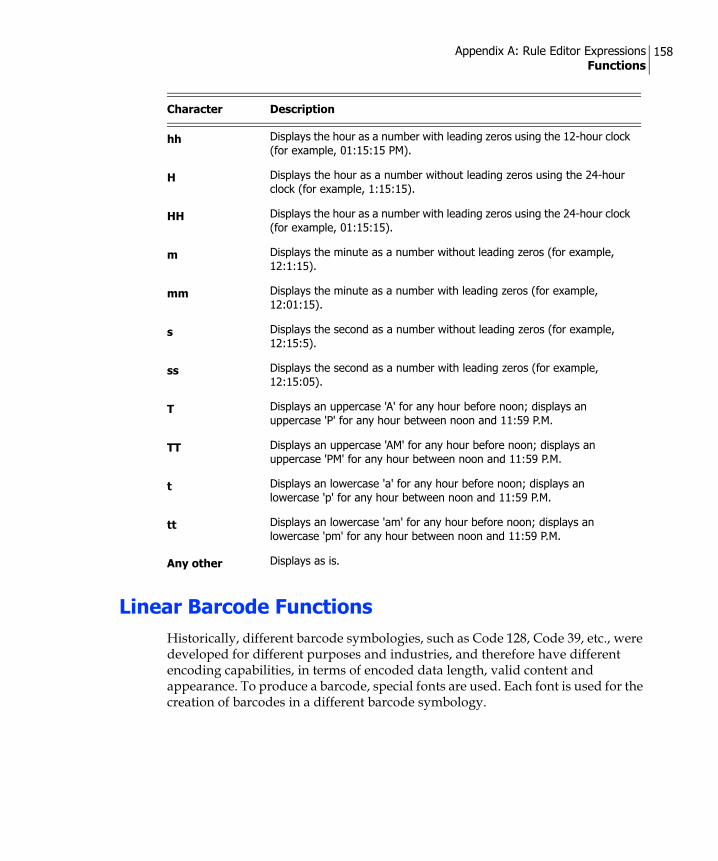
Appendix A: Rule Editor Expressions Functions
158
Linear Barcode FunctionsHistorically, different barcode symbologies, such as Code 128, Code 39, etc., were developed for different purposes and industries, and therefore have different encoding capabilities, in terms of encoded data length, valid content and appearance. To produce a barcode, special fonts are used. Each font is used for the creation of barcodes in a different barcode symbology.
hh Displays the hour as a number with leading zeros using the 12-hour clock (for example, 01:15:15 PM).
H Displays the hour as a number without leading zeros using the 24-hour clock (for example, 1:15:15).
HH Displays the hour as a number with leading zeros using the 24-hour clock (for example, 01:15:15).
m Displays the minute as a number without leading zeros (for example, 12:1:15).
mm Displays the minute as a number with leading zeros (for example, 12:01:15).
s Displays the second as a number without leading zeros (for example, 12:15:5).
ss Displays the second as a number with leading zeros (for example, 12:15:05).
T Displays an uppercase 'A' for any hour before noon; displays an uppercase 'P' for any hour between noon and 11:59 P.M.
TT Displays an uppercase 'AM' for any hour before noon; displays an uppercase 'PM' for any hour between noon and 11:59 P.M.
t Displays an lowercase 'a' for any hour before noon; displays an lowercase 'p' for any hour between noon and 11:59 P.M.
tt Displays an lowercase 'am' for any hour before noon; displays an lowercase 'pm' for any hour between noon and 11:59 P.M.
Any other Displays as is.
Character Description

Appendix A: Rule Editor Expressions Functions
159
Creating a barcode involves two steps, as follows:
1. An input string (the barcode "value") is encoded using a font-specific (and barcode-symbology-specific) encoding function, resulting in an encoded string.
2. The encoded string is rendered using the barcode font.
Fonts of the same barcode symbology from different vendors require slightly different encoding functions, depending on the font vendor's implementation. Therefore, the font and the encoding function are tightly bonded; a string is always encoded for a specific font and may not work with a different font for the same barcode symbology.
Defining a Dynamic Barcode Content ObjectYou can define a dynamic barcode Content Object if your Data Source has a field that should be displayed as a barcode. By defining the Content Object type as Text with Style, you can select fonts for the barcode, apply a style to it, or override any built-in style definitions (see Overriding Style Definitions on page 53). All the barcode fonts are provided as part of the uDirect Installation CD.
Figure 85: Barcode Creation Flow Chart
3 3 0 2 3 8 1 2InputString
1. Encoding Function
V X 3 1 H B C DEncoded String D V
2. Font
2 0

Appendix A: Rule Editor Expressions Functions
160
To define a dynamic barcode Content Object:1. Right-click anywhere in the uDirect Palette (Figure 14 on page 23) and select
New Content Object….The New Content Object dialog box is displayed (Figure 86).
2. In the Name field, enter a name for the Content Object.
3. From the Type drop-down list, select Text with Style and select the Extended Functions check box.
4. In the Rule section, apply the XMPCode39 function to your barcode field.
5. If you wish to override the built-in font style, click the plus sign next to the Apply Style drop-down list to set the correct font for this barcode text.The Style Overrides dialog is displayed (Figure 38 on page 54).
Note: Text tagged with a barcode Content Object must use regular quotes, “, and not typographer’s quotes (curly). The quote character sometimes appears in the result of barcode functions. If InDesign is set to use typographer’s quotes, invalid barcodes may be created by uDirect. To set InDesign to use regular quotes, do the following before using Dynamic Print: Go to Edit -> Preferences ->Type... and un-check Use Typographer’s Quotes.
Figure 86: New Content Object—Barcode dialog
Note: We are using the XMPCode39 function as an example. In your Campaign, you may use a different barcode function.

Appendix A: Rule Editor Expressions Functions
161
6. Select the Override font check box, select XMPCode 39 from the drop-down list, and click OK to close the dialog.
7. Click OK to close the New Content Object dialog.
8. Scroll through the Data Source records to see the barcode Content Object dynamically change within the image.
The following table summarizes the available barcode fonts supported by uDirect and their corresponding QLingo functions (for versions 3.2 and 4.0.x).
Note: If the selected font is missing within InDesign, the Content Object displays in pink. Make sure all the barcode fonts have been installed correctly. They are provided on the uDirect installation CD.
Barcode Symbology
3.2 Functiona
4.0.x Function Font Name
Valid Characters
Valid Input Length
Code 128 BarCode128BBarCode128C
XMPBarCode128
XMP128.ttfXMP128N.ttfXMP128W.ttf
All 128 ASCII characters
Not limited
CODABAR CODABAR XMPCODABAR XMPCODABAR.ttf A-D as first or last characters
Not limited
Code 39 Code39 XMPCode39 XMPCode39.ttfXMPCode39N.ttfXMPCode39W.ttfXMPCode39T.ttfXMPCode39TN.ttfXMPCode39TW.ttf
0-9 A-Z - $ / + % space
Variable. Output optionally contains a checksum. Maximum length: without checksum: 30, with checksum: 27
EAN13 EAN13 XMPEAN13 XMPEAN13.ttf 0-9 12
EAN8 EAN8 XMPEAN8 XMPEAN8.ttf 0-9 7
Interleaved 2 of 5 (ITF)
ITF XMPInt2Of5 XMPInt2of5.ttfXMPInt2of5N.ttfXMPInt2of5W.ttf
0-9 Not limited, but must be even. If odd, '0' is added at the start point (left side).
MSI (Modified Plessey)
MSI XMPMSI XMPMSI.ttf 0-9 Variable. Maximum length: 13

Appendix A: Rule Editor Expressions Functions
162
XMPBarCode128 Function
The XMPBarCode128 function creates a barcode 128 encoding of the expression.
Syntax:XMPBarCode128 (expression)
XMPCODABAR Function
The XMPCODABAR function creates a CODABAR encoding of the expression.
Syntax:XMPCODABAR (expression)
OneCode N.A. XMPOneCode XMPOneCode.ttf 0-9. The second digit must be in range of 0–4
20, 25, 29 or 31.
POSTNET (USPSZIP)
USPSZIP, POSTNET
XMPPOSTNET XMPPOSTNET.ttf 0-9 5, 9, or 11
UPCA UPCA XMPUPCA XMPUPCA.ttf 0-9 11
UPCE UPCE XMPUPCE XMPUPCE.ttf 0-9 11
a. Although barcode functions of uDirect version 3.2 are still supported, you cannot use them with the new barcode fonts that are supplied with the uDirect version 4.0.x software pack. To get the full barcode fonts support, use the new barcode functions of uDirect 4.0.x, as described in the table above and in the sections that follow.
Note: All “Valid Input Length” values refer to the function input string only, without correction characters and start/stop characters created in the barcode output. All barcode functions accept a single parameter, which is the barcode input, except for XMPCode39 and XMPInt2Of5 that accept two parameters: the barcode input, followed by a Boolean parameter indicating whether or not a checksum should be generated. For example: XMPCode39 (“123456789”, true)
Barcode Symbology
3.2 Functiona
4.0.x Function Font Name
Valid Characters
Valid Input Length

Appendix A: Rule Editor Expressions Functions
163
XMPCode39 Function
The XMPCode39 function creates a Code39 encoding of expression1, and if expression2 is evaluated to true, then adds a checksum.
Syntax:XMPCode39 (expression1, expression2)
XMPEAN13 Function
The XMPEAN13 function creates an EAN13 encoding of the expression.
Syntax:XMPEAN13 (expression)
XMPEAN8 Function
The XMPEAN8 function creates an EAN8 encoding of the expression.
Syntax:XMPEAN8 (expression)
XMPInt2Of5 Function
The XMPInt2Of5 function creates an Interleaved 2 of 5 encoding of expression1, and if expression2 is evaluated to true, then adds a checksum. Note that the valid input length is not limited but must be even; if odd, the value '0' is added at the starting point (left side).
Syntax:XMPInt2Of5 (expression1, expression2)
XMPMSI Function
The XMPMSI function creates an MSI encoding of the expression.
Syntax:XMPMSI (expression)

Appendix A: Rule Editor Expressions Functions
164
XMPOneCode Function
The XMPOneCode function creates a OneCode encoding of the expression.
Syntax:XMPOneCode (expression)
XMPPOSTNET (USPSZIP) Function
The XMPPOSTNET function gets the digits in expression1, validates that the number of digits is 5, 9 or 11 and adds a digit at the end for check sum, concatenates expression2 character to the start and end of the result; expression2 is optional and defaults to empty string.
Syntax:XMPPOSTNET (expression1, expression2)
XMPUPCA Function
The XMPUPCA function creates a UPCA encoding of the expression.
Syntax:XMPUPCA (expression)
XMPUPCE Function
The XMPUPCE function creates a UPCE encoding of the expression.
Syntax:XMPUPCE (expression)
2D Barcode Functions
2D Barcode Functions for Print MediauDirect supports two-dimensional (2D) barcode symbology for encoding variable information in a dynamic InDesign document.
Both linear and 2D barcode values are calculated by applying Content Object Rules to the linked Data Source, so the resolved barcodes are unique to each recipient.

Appendix A: Rule Editor Expressions Functions
165
2D barcodes contain more information than linear barcodes, by using both the horizontal and the vertical dimensions to pack data. While linear barcodes are created using Text Content Objects, 2D barcodes are created using Graphic Content Objects. During production, the 2D barcode Content Object is replaced with recipient-specific images in the EPS format, which are embedded into the Print Output file.
uDirect offers the following 2D barcode symbologies:
• PDF417
• Data Matrix
• QR-Code
• Aztec Code
• MaxiCode
• MicroPDF417
The following sections provide information on Defining a Dynamic 2D Barcode, describe the 2D Barcode Valid Input Data and give instructions on Adding a Dynamic 2D Barcode to your Document.
Defining a Dynamic 2D BarcodeThis section explains how to define a dynamic 2D barcode using a Graphic ADOR Object.
To add a 2D barcode ADOR Object:1. Right click anywhere in the uDirect Palette and select New Content Object…
The Rule Editor’s New Content Object dialog is displayed (Figure 87).
Note: uDirect versions 4.5 and 4.5.x support 2D barcodes on the Windows platform. Starting from version 4.6, uDirect supports 2D barcodes both on Windows and on the Mac.

Appendix A: Rule Editor Expressions Functions
166
2. From the Type drop-down list, select Graphic. The Rule section of the dialog displays the graphic-specific options.
3. Check the Extended Functions check box.
4. From the functions drop-down list, select the 2D barcode function of the symbology you wish to use. The function names consist of the “XMP2D” prefix and the symbology name. For example, XMP2DPDF417 is the function for the PDF417 symbology.
5. Between the function parentheses, enter the data you wish to encode in the barcode. In this example, the encoded information is the Index field of the linked Data Source. For more information on the data you can encode, see 2D Barcode Valid Input Data on page 171.
6. Click OK to accept your settings.The new 2D barcode Content Object is added to the uDirect Palette's Content Objects list.
7. Use the 2D barcode Content Object to tag a graphic box in your Document (by selecting the graphic box and then double-clicking the 2D barcode Content Object in the uDirect Palette).
Figure 87: New Content Object dialog-2D Barcode (XMP2DQRCode)

Appendix A: Rule Editor Expressions Functions
167
8. Scroll through the Data Source records using the record selection box (located at the bottom of the uDirect Palette) to see how the tagged object dynamically changes in the Document for each recipient (Figure 88).
Customizing the 2D Barcode ParametersThe Content Object's QLingo expression specifies the name of a Data Source field, or an expression, used to personalize the barcode for each recipient. By default, the QLingo expression includes a single parameter: the string to be encoded (for example, “XMPie”).
This QLingo expression may include a second, optional parameter: a string, consisting of one or more barcode parameter name-value pairs, used to customize the barcode parameters.
The most commonly-used optional parameter is ModuleWidth (see Customizing the 2D Barcode's Module Width Parameter on page 168).
In addition, you may wish to configure the CodePage parameter, which determines the Code Page used to encode the barcode string in the selected barcode symbology (see Customizing the 2D Barcode's CodePage Parameter on page 169).
Figure 88: 2D Barcode in the Document per uDirect Palette Record
Note: The barcode image is best viewed in the InDesign document when setting the display performance to High Quality Display.
Note: The name-value pairs are separated by semi colons (;).

Appendix A: Rule Editor Expressions Functions
168
You may also set a BinaryString parameter, which is used to treat the input as a stream of binary data that is not affected by the CodePage (see Customizing the 2D Barcode's BinaryString Parameter on page 171).
For information on additional parameters you can customize, please contact XMPie Support.
Customizing the 2D Barcode's Module Width Parameter
The Module Width is the width of the barcode's smallest element. It is specified in units of thousandths of a millimeter (1/1000mm). By default, the module width is set to 0.254 mm. This value may be overridden by editing the QLingo code of the 2D barcode's Content Object.
To change the default Module Width:The following procedure shows how to change the default module width of the XMP2DPDF417 Barcode Content Object, defined in the previous section (see Defining a Dynamic Barcode Content Object on page 159).
1. In the Content Object's Rule Editor, click View QLingo....
2. In the QLingo Rule dialog, add a second parameter to the QLingo expression as follows:
Add a comma (,) after your encoded text (in this case,"|->[Index]"). Add a string QLingo parameter: quotation marks ('') surrounding the 2D barcode ModuleWidth parameter and its custom value (in this case, 0.508 mm).
The updated QLingo Expression is as follows:XMP2DPDF417("|->[Index]", "ModuleWidth=508")
Figure 89 shows the updated QLingo Rule of the XMP2DPDF417 Barcode.

Appendix A: Rule Editor Expressions Functions
169
3. Click OK to save your changes and close the QLingo Rule dialog.
4. Back in the Edit Content Object dialog, click OK to save your changes.The updated barcode parameter settings are shown in the Document (in this case, the barcode appears larger).
Customizing the 2D Barcode's CodePage Parameter
For most 2D barcode symobologies, the default Code Page used is the one set in the machine’s Regional and Language Options. The only exceptions are:
• QR-Code—whose default Code Page is ShiftJIS932.
• PDF417, MicroPDF—whose default Code Page is ASCIIExtended437.
Figure 89: Updated QLingo Rule for XMP2DPDF417 Barcode with a Second Parameter (ModuleWidth)
Note: When adjusting the module width to a fixed value, the resulting barcode can be larger than the bounding rectangle. To avoid clipping, ensure the entire barcode can be displayed with the maximum data content and widen the barcode object if needed.

Appendix A: Rule Editor Expressions Functions
170
On Windows machines, you have the option to set the required Code Page using the CodePage parameter. Note that this parameter has no effect on the Mac.
Possible values are:
• Default—as described above.
• Local—the Code Page that is set in the machine’s Regional and Language Options.
• Windows1252
• ISO8859-1
• ASCIIExtended437
• UTF8
• Korean949
• ShiftJIS932
• SimplifiedChinese936
• TraditionalChinese950
• ANSICyrillic1251
• KOI8-R20866
To change the Code Page:1. In the Content Object's Rule Editor, click View QLingo... (Figure 87 on
page 166)
2. In the QLingo Rule dialog (Figure 89 on page 169), add a second parameter to the QLingo expression as follows:
Add a comma (,) after your encoded text (in this case,"|->[Index]"). Add a string QLingo parameter: quotation marks ('') surrounding the 2D barcode CodePage parameter and its custom value (for example, UTF8).
The updated QLingo Expression is as follows:XMP2DPDF417("|->[Index]", "CodePage=UTF8")
Note:
• If your input data contains characters that are not part of the default code page, these characters are lost (do not appear in the barcode).
• If the default Code Page is not the one your barcode reader expects, the wrong information (other characters) appears in the barcode.
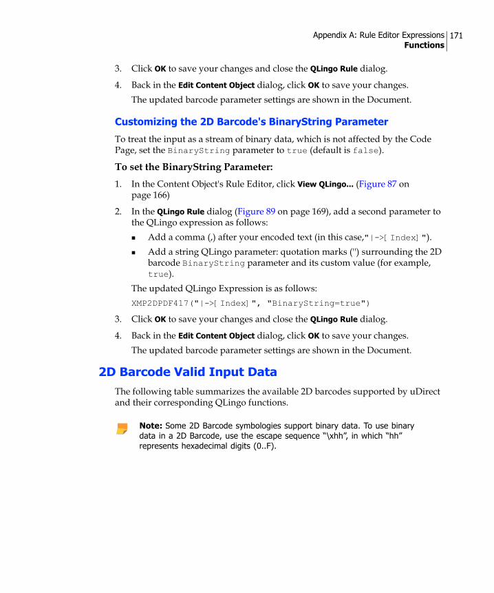
Appendix A: Rule Editor Expressions Functions
171
3. Click OK to save your changes and close the QLingo Rule dialog.
4. Back in the Edit Content Object dialog, click OK to save your changes.The updated barcode parameter settings are shown in the Document.
Customizing the 2D Barcode's BinaryString Parameter
To treat the input as a stream of binary data, which is not affected by the Code Page, set the BinaryString parameter to true (default is false).
To set the BinaryString Parameter:1. In the Content Object's Rule Editor, click View QLingo... (Figure 87 on
page 166)
2. In the QLingo Rule dialog (Figure 89 on page 169), add a second parameter to the QLingo expression as follows:
Add a comma (,) after your encoded text (in this case,"|->[Index]"). Add a string QLingo parameter: quotation marks ('') surrounding the 2D barcode BinaryString parameter and its custom value (for example, true).
The updated QLingo Expression is as follows:XMP2DPDF417("|->[Index]", "BinaryString=true")
3. Click OK to save your changes and close the QLingo Rule dialog.
4. Back in the Edit Content Object dialog, click OK to save your changes.The updated barcode parameter settings are shown in the Document.
2D Barcode Valid Input DataThe following table summarizes the available 2D barcodes supported by uDirect and their corresponding QLingo functions.
Note: Some 2D Barcode symbologies support binary data. To use binary data in a 2D Barcode, use the escape sequence “\xhh”, in which “hh” represents hexadecimal digits (0..F).

Appendix A: Rule Editor Expressions Functions
172
2D Barcode Symbology Function Valid Characters
PDF417 XMP2DPDF417 Alphanumeric (ASCII 0.. 255)
Data Matrix XMP2DDataMatrix Alphanumeric (ASCII 0.. 255) and/or bytes
QR-Code XMP2DQRCode Alphanumeric and/or bytes, Kanji character set
Aztec Code XMP2DAztecCode ASCII 0-127 + ISO 8859-1
MaxiCode XMP2DMaxiCode Alphanumeric (ASCII 0.. 255) and/or bytes
MicroPDF417 XMP2DMicroPDF Alphanumeric and/or bytes

Appendix A: Rule Editor Expressions Functions
173
Creating 2D Barcode FunctionsThis section explains how to create each 2D Barcode function.
XMP2DPDF417 Function
The XMP2DPDF417 function creates a PDF417 encoding of the expression.
The first parameter, yourEncodedText, is the name of a Data Source field or an expression used to personalize the barcode (for example, “XMPie”).
The second parameter ("Parameter 1=Value 1; Parameter 2=Value 2") is optional, allowing you to customize the default barcode settings (for example, "ModuleWidth=508").
Syntax:XMP2DPDF417 (yourEncodedText, "Parameter 1=Value 1; Parameter 2=Value 2")
XMP2DAztecCode Function
The XMP2DAztecCode function creates an AztecCode encoding of the expression.
The first parameter, yourEncodedText, is the name of a Data Source field or an expression used to personalize the barcode (for example, “XMPie”).
The second parameter ("Parameter 1=Value 1; Parameter 2=Value 2") is optional, allowing you to customize the default barcode settings (for example, "ModuleWidth=508").
Syntax:XMP2DAztecCode (yourEncodedText, "Parameter 1=Value 1; Parameter 2=Value 2")
XMP2DDataMatrix Function
The XMP2DDataMatrix function creates a DataMatrix encoding of the expression.
The first parameter, yourEncodedText, is the name of a Data Source field or an expression used to personalize the barcode (for example, “XMPie”).
The second parameter ("Parameter 1=Value 1; Parameter 2=Value 2") is optional, allowing you to customize the default barcode settings (for example, "ModuleWidth=508").

Appendix A: Rule Editor Expressions Functions
174
Syntax:XMP2DDataMatrix (yourEncodedText, "Parameter 1=Value 1; Parameter 2=Value 2")
XMP2DMaxiCode Function
The XMP2DMaxiCode function creates a MaxiCode encoding of the expression.
The first parameter, yourEncodedText, is the name of a Data Source field or an expression used to personalize the barcode (for example, “XMPie”).
The second parameter ("Parameter 1=Value 1; Parameter 2=Value 2") is optional, allowing you to customize the default barcode settings (for example, "ModuleWidth=508").
Syntax:XMP2DMaxiCode (yourEncodedText, "Parameter 1=Value 1; Parameter 2=Value 2")
XMP2DMicroPDF Function
The XMP2DMicroPDF function creates a MicroPDF encoding of the expression.
The first parameter, yourEncodedText, is the name of a Data Source field or an expression used to personalize the barcode (for example, “XMPie”).
The second parameter ("Parameter 1=Value 1; Parameter 2=Value 2") is optional, allowing you to customize the default barcode settings (for example, "ModuleWidth=508").
Syntax:XMP2DMicroPDF (yourEncodedText, "Parameter 1=Value 1; Parameter 2=Value 2")
XMP2DQRCode Function
The XMP2DQRCode function creates a QRCode encoding of the expression.
The first parameter, yourEncodedText, is the name of a Data Source field or an expression used to personalize the barcode (for example, “XMPie”).
The second parameter ("Parameter 1=Value 1; Parameter 2=Value 2") is optional, allowing you to customize the default barcode settings (for example, "ModuleWidth=508").

Appendix A: Rule Editor Expressions Functions
175
Syntax:XMP2DQRCode (yourEncodedText, "Parameter 1=Value 1; Parameter 2=Value 2")
Adding a Dynamic 2D Barcode to your Document1. Create a graphic frame that will display the barcode.
2. Create a Graphic ADOR Object containing the relevant barcode definition (for detailed instructions, see Defining a Dynamic 2D Barcode on page 165).
3. Tag the graphic frame with the Graphic Content Object.
The recipient-specific barcode is displayed in the graphic frame (Figure 90).
String Functions
LCase Function
The LCase function assigns lower case formatting. It changes the expression to lower case characters and returns a string. The expression is always regarded as a string; even if it appears as a date or number, it will be interpreted as a string.
Syntax:Lcase(expression)
Example:Lcase("HELLO") returns the value "hello".
Figure 90: Recipient-Specific Barcode in Graphic Frame
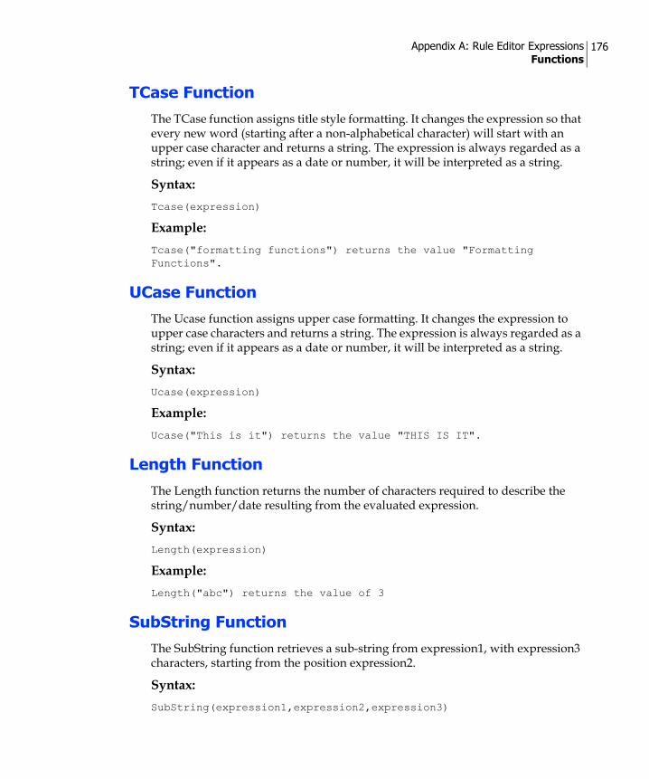
Appendix A: Rule Editor Expressions Functions
176
TCase Function
The TCase function assigns title style formatting. It changes the expression so that every new word (starting after a non-alphabetical character) will start with an upper case character and returns a string. The expression is always regarded as a string; even if it appears as a date or number, it will be interpreted as a string.
Syntax:Tcase(expression)
Example:Tcase("formatting functions") returns the value "Formatting Functions".
UCase Function
The Ucase function assigns upper case formatting. It changes the expression to upper case characters and returns a string. The expression is always regarded as a string; even if it appears as a date or number, it will be interpreted as a string.
Syntax:Ucase(expression)
Example:Ucase("This is it") returns the value "THIS IS IT".
Length Function
The Length function returns the number of characters required to describe the string/number/date resulting from the evaluated expression.
Syntax:Length(expression)
Example:Length("abc") returns the value of 3
SubString Function
The SubString function retrieves a sub-string from expression1, with expression3 characters, starting from the position expression2.
Syntax:SubString(expression1,expression2,expression3)

Appendix A: Rule Editor Expressions Functions
177
Where:
• expression1 is always regarded as a string; even if it appears as a date or number, it will be interpreted as a string.
• expression2 indicates the starting position of the substring. For example, 0 represents the first character position in expression1, 1 represents the second character position, etc.
• expression3 is the number of characters retrieved.
For example, 3 retrieves three characters, 0 retrieves an empty string, etc. A value of –1 indicates that all characters until the end of expression1 should be retrieved.
Examples:SubString("abcd",1,2)="bc"
SubString("James",2,2)="me"
SubString(1973,0,2)="19"
SubString("James",2,-1)="mes"
Trim Function
The Trim function trims leading and trailing white spaces in the string (expression).
Syntax:Trim(expression)
Example:Trim(" hello WORLD ") = "hello WORLD"
LTrim Function
The LTrim function trims leading white spaces in the string (expression).
Syntax:LTrim(expression)
Example:LTrim(" hello WORLD ") = "hello WORLD "

Appendix A: Rule Editor Expressions Functions
178
RTrim Function
The RTrim function trims trailing white spaces in the string (expression).
Syntax:RTrim(expression)
Example:RTrim(" hello WORLD ") = " hello WORLD"
Find Function
The Find function gets the character index (zero based) in the string (expression1) where the string (expression2) is found. The search starts from the character index (expression3 – zero based). The result is -1 in case the string is not found.
Syntax:Find(expression1, expression2, expression3)
Example:Find("hello WORLD", "WORLD", 0) = 6
Replace Function
The Replace function replaces a part of the string (expression1) starting from character index (expression3 – zero based) of length (expression4) with the string (expression 2).
Syntax:Replace(expression1, expression2, expression3, expression4)
Example:Replace("hello WORLD", "EARTH", 6, 5) = "hello EARTH"
FindAndReplace Function
The FindAndReplace function replaces all instances of the string (expression2) in the string (expression1) with the string (expression3).
Syntax:FindAndReplace(expression1, expression2, expression3)

Appendix A: Rule Editor Expressions Functions
179
Example:FindAndReplace("hello WORLD", "WORLD", "EARTH") = "hello EARTH"
Conversion FunctionsConversion functions allow you to convert different types of data.
AsBoolean Function
The AsBoolean function evaluates the expression as True/False. The Null value is false regardless of the data type. For a Number expression, 0 is False; otherwise it is True. For String expressions, Empty String is False; otherwise it is True. Date expression is always true.
Syntax:AsBoolean(expression)
Example:AsBoolean(1) = True
AsDate Function
The AsDate function attempts to evaluate the expression as a date, if possible.
For example, the string "23/02/1994" will be evaluated as 23/02/1994.
If the expression cannot be evaluated as a date, the function will fail and an error will be reported.
Null value conversion will return the current date/time.
Number value conversion assumes you are calculating the date starting 31/12/1899 and adds the given number as the number of days elapsed (for example: AsDate(1) = 31/12/1899).
Syntax:AsDate(expression)
Example:AsDate("02\07\2006") = 02\07\2006
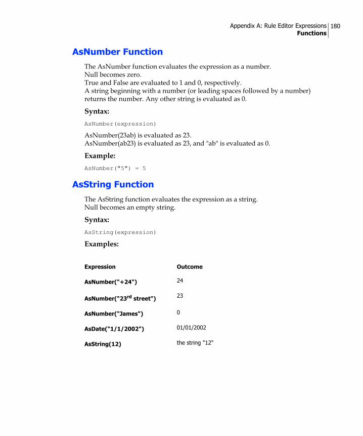
Appendix A: Rule Editor Expressions Functions
180
AsNumber Function
The AsNumber function evaluates the expression as a number. Null becomes zero. True and False are evaluated to 1 and 0, respectively. A string beginning with a number (or leading spaces followed by a number) returns the number. Any other string is evaluated as 0.
Syntax:AsNumber(expression)
AsNumber(23ab) is evaluated as 23. AsNumber(ab23) is evaluated as 23, and "ab" is evaluated as 0.
Example:AsNumber("5") = 5
AsString Function
The AsString function evaluates the expression as a string. Null becomes an empty string.
Syntax:AsString(expression)
Examples:
Expression Outcome
AsNumber("+24") 24
AsNumber("23rd street") 23
AsNumber("James") 0
AsDate("1/1/2002") 01/01/2002
AsString(12) the string "12"

Appendix A: Rule Editor Expressions Functions
181
GetEnv FunctionsEnvironment constants allow you to retrieve data during production.
Syntax:Constants are used as follows:GetEnv("constant name")
Current Record Number
The environment constant CurRecordNumber returns the number of the current record being processed.
Syntax:GetEnv ("CurRecordNumber")
Example:GetEnv("CurRecordNumber") = 5
Print Media
The environment constant PrintMedia returns True if the production is of a print document.
Syntax:GetEnv("PrintMedia")
Proof Set
The environment constant ProofSet returns True if the production is of a Proof Set.
Syntax:GetEnv("ProofSet")
HTML Media
The environment constant HTMLMedia returns True if the production is of html: on demand, email, or proof html.
Syntax:GetEnv("HTMLMedia")

Appendix A: Rule Editor Expressions Functions
182
Text Media
The environment constant TextMedia returns True if the production is of text: SMS, text.
Syntax:GetEnv("TextMedia")
Host Application The environment constant HOST_APPLICATION returns the name of the application that executes the Plan. Possible return values are listed below.
Syntax:GetEnv("HOST_APPLICATION")
Value Description
uProduce The Plan is executed by uProduce. uProduce uses a Plan to produce cross-media outputs. • For Print Campaigns, uProduce can produce Print and Proof jobs,
as well as Proof Sets. • For Web Campaigns, uProduce can produce ICPs and email
batches.• For Cross-Media Campaigns, uProduce can perform all of the
above production types.
InDesign The Plan or expression is executed by uDirect or uCreate Print. uDirect and uCreate Print can produce the following types of output:• Print — by choosing the Palette’s Dynamic Print... menu option.• Proof Set — by choosing the Palette’s Export Proof Set... menu
option.
uPlan The Plan is executed by uPlan. uPlan uses a Plan to produce Proof Sets.

Appendix A: Rule Editor Expressions Functions
183
Job Type The environment constant JOB_TYPE returns the job type defined in the job ticket. Possible return values are listed below.
Value Description
PRINT A Print job. • In uDirect/uCreate Print, this value indicates a job created using
the Palette’s Dynamic Print... menu option.• In uProduce, this value indicates a job created by clicking the
Process button of the Document Details page.
PROOF A Proof job. This value indicates a job created using uProduce, by clicking the Proof button of the Document Details page.
PROOF_SET A Proof Set job.• In uDirect/uCreate Print, this value indicates a job created using
the Palette’s Export Proof Set... menu option.• In uProduce, this value indicates a job created by clicking the
Generate button of the Plan Details page.• In uPlan, this value indicates a job created using one of the Data
menu’s “Generate” options (for example, Generate Proof Set... option).
ON_DEMAND A Dynamic HTML production job (previously known as HTML production). This value indicates a job created using uProduce, by clicking the Deploy button of the Web (HTML or TXT) Document Details page.Note: This option is available for backward compatibility purposes. To create a web site with Dynamic HTML, it is recommended to use the Interactive Content Port (ICP) solution. For details, see the e-Media User Guide.
RECORD_SET An Interactive Content Port (ICP) job. This value indicates that the Plan is executed by an ICP. This is normally the case with a Web Campaign created by RURL Wizard or by uCreate XM.
FLAT A job that collects information on a future Print job.Several FLAT jobs of the same Document are later aggregated and used as the input of a single Print job. This is normally the case with job aggregation created by uStore.
EMAIL_MARKETING An e-mail batch job.This value indicates a job created by clicking the Send button of the Email Activity Details page.

Appendix A: Rule Editor Expressions Functions
184
Syntax:GetEnv("JOB_TYPE")
Document Type The environment constant DOCUMENT_TYPE returns the Document type defined in the job ticket. Possible return values are listed below.
Syntax:GetEnv("DOCUMENT_TYPE")
EMAIL_MARKETING_TEST
An e-mail batch test job.This value indicates a job created by clicking the Test button of the Email Activity Details page.
T
Note: All of the above job types may also be created using the XMPie API SDK. For details, see the API documentation.
Value Description
Value Description
HTML An HTML Document
INDD An Adobe InDesign Document
TXT A text Document
XLIM An XMPie proprietary XLIM Document
T
Note: This expression returns a valid value only for the following job types (other job types return an empty string):
• PROOF
• ON_DEMAND
• EMAIL_MARKETING
• EMAIL_MARKETING_TEST

Appendix A: Rule Editor Expressions Functions
185
Miscellaneous Operators and Functions
Abort Operator
The Abort operator serves to abort job processing (Plan execution) based on data values and Logic during the calculation of an Content Object value. The job itself is marked as aborted and a message reports that the job was aborted due to the Abort operation.
Example:Say we wish to abort the current job if we find out that specific data is missing. For example, if the last name of a customer is missing we will abort the job. In this case, the expression for the last name Content Object will appear as follows:If(|->[Last Name] = NULL or |->[Last Name] = "")
Abort
else
|->[ Last Name]
ReportMessage Function
The ReportMessage function inserts a message into the message list during production.
Syntax:ReportMessage(message)
This function is different from all other functions because it does not have a value that can be used to populate the Content Objects; therefore, it must be followed by an expression that has a value. You can use several calls to this function one after the other, but the last expression in the call list must be an expression that evaluates to some value (that is, not a ReportMessage function):ReportMessage(msg1)
ReportMessage(msg2)
…
ReportMessage(msgn)
Expression
Example:Say, for example, we want to report a message in case a record is skipped as a result of the Skip operator.

Appendix A: Rule Editor Expressions Functions
186
In this example, we wish to create a Campaign for customers that have credit of more than 10000. A Content Object defined for the customer’s credit may appear as shown on the next page.If(|->[Credit] < 10000)
{
ReportMessage("Record number " & GetEnv("CurRecordNumber") & " was skipped")
Skip
}
else
|->[Credit]
Skip Operator
The Skip operator skips the current record during job processing (Plan execution), without affecting the success of the job. The Skip operator enables uProduce to continue the job without creating customer communications for specific recipients based on their data values and the Logic defined for calculated Content Object values. By default, no special messages are displayed when a record is skipped. To specify that a message should be reported, you can use the ReportMessage Function on page 185.
Example:Say we want to create a Campaign directed at customers that have credit of more than 10000, and skip those that have less than 10000. In this case, the Content Object for the customer’s credit may appear as follows:If(|->[Credit] < 10000)
Skip
else
|->[Credit]
Call FunctionThe Call function is used for integrating a Plan with QLingo extension modules. For more information about the QLingo extension mechanism, contact XMPie support at [email protected].
Syntax:Call dllName.functionName(parameters)
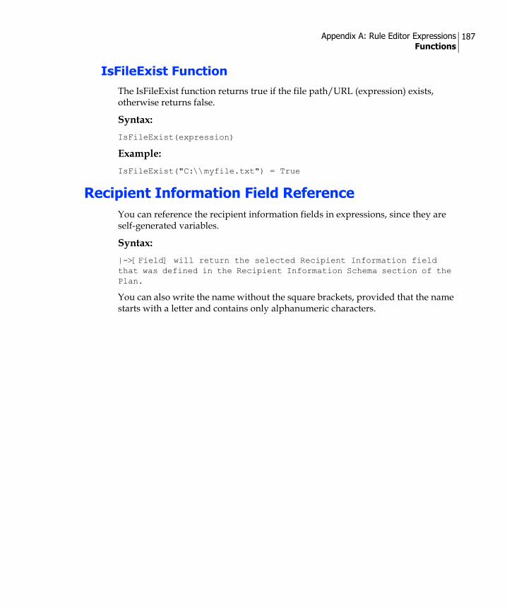
Appendix A: Rule Editor Expressions Functions
187
IsFileExist FunctionThe IsFileExist function returns true if the file path/URL (expression) exists, otherwise returns false.
Syntax:IsFileExist(expression)
Example:IsFileExist("C:\\myfile.txt") = True
Recipient Information Field ReferenceYou can reference the recipient information fields in expressions, since they are self-generated variables.
Syntax:|->[Field] will return the selected Recipient Information field that was defined in the Recipient Information Schema section of the Plan.
You can also write the name without the square brackets, provided that the name starts with a letter and contains only alphanumeric characters.
Appendix B
Working with uChartuChart is the XMPie add-on to uDirect that allows you to use a Table Content Object as a Data Driven Graphic.
When you add a Table Content to a graphic frame (as opposed to a text frame), the data is automatically converted from tabular format into data driven graphic format. To control the type of graphics displayed (for example, pie charts, bar charts, etc.), you need to use the uChart add-on to uDirect, which enables you to launch the uChart Properties dialog.
To display the Table Content data in Data Driven Graphic format:1. Click any of the graphic frame tool icons (for example, Rectangle Frame
Tool icon) and use the mouse to draw a placeholder frame in the document.
2. In the uDirect Palette, double-click the name of the desired Table Content Object. The placeholder frame displays a pie chart indicating that the frame has been associated with the selected Table Content; the pie chart does not reflect the Table Content Object data at this time.
3. Specify how the Table Content Object data should be presented in this graphic, by right clicking anywhere in the graphic frame and selecting uChart Properties from the context menu. The uChart Properties dialog is displayed (Figure 91 on page 189).
Note: You need uChart license to use data driven graphics.

Appendix B: Working with uChart 189
4. Make any necessary modifications, as explained in the table at the end of this section.
5. Click OK to close the dialog. The graphic is updated according to the settings you have specified.
6. When the Table Content Object column values populate the data driven graphic, the appropriate image is displayed for each recipient.The Dynamic Table Properties dialog includes the following fields and options:
Figure 91: uChart Properties dialog

Appendix B: Working with uChart 190
Select this option… To…
Type Select the desired type of graphic representation. Available options are Pie, Bar, Line, Area and Compound. Note that the fields in the dialog differ slightly, depending on the selected graphic type.
Colors & Data Choose the color in which the graphic will be shown (you can add colors to the list by selecting Windows > Swatches from the InDesign menu).
Colors & Data (Pie charts only)
Select either a single color or multiple colors.To select a color, click the adjacent gray box. The selection is
indicated by a green V mark .Select as many colors as needed, and use the Up and Down buttons to determine their order. If the number of slices is larger than the number of colors you have selected, the colors’ shades will be used to distinguish between slices.Note that the number of selected colors is indicated at the bottom of this pane.
Colors & Data (Bar, Line, Area or Compound)
Choose the following:Select a single color by clicking the color box. The adjacent gray box is colored white to indicate your selection.Select the Table Content Object column to be shown in the chosen color, and specify the text to be shown as the data’s label, by double clicking the color name (or description).The Series Color Assignment dialog is displayed. You can use this dialog to choose the relevant column from the Series drop-down list, and enter the label text into the Display Name field (Figure 92).Note that when using a Compound chart, the last selected color in the Color list is assigned to the Line graph.
Figure 92: Series Color Assignment dialog
Options (All Types)
Font Select the font typeface and size of all text appearances (for example, the legend text, the bar chart grid text, etc.).

Appendix B: Working with uChart 191
Legend Add a legend by choosing its location with respect to the graphic from the drop-down list. Available options include None, Left or Right.Pie charts include additional options: Circular and Legend Only, which can be set per slice (that is, per Table Content Object column).
3D Effect Add a three dimensional perspective to the graphic.
Options (Pie Chart only)
Separate Slices Break apart and separate the different slices of the chart.
Merge Small Slices Combine all slices whose value is less than a specified amount into a single slice.
If less than Specify the minimal percentage of the data a value must represent in order to be displayed as a separate slice. All slices whose values are lower than this percentage will be combined into a single general slice, whose default Title is Other.
Title Enter the title to be given to the general slice, which merges all Small Slices whose values are less than the specified percentage.The default Title is Other.
Options (Bar, Line or Area)
Show Bar Values Include the bar values in the graphic.
Show Grid Display the graphic on a grid.
Annotate Specify which of the axes on which the graphic is displayed are to be annotated. Available options are None, X Axis, Y Axis and Both Axes.
X Series Select the Table Content Object column to be used as the graphic’s X-axis from the drop-down list.
Preview See an advance viewing of the graphic, reflecting the properties you specify in this dialog.Note that your changes are saved only after you click OK or Apply.
Select this option… To…
Type Select the desired type of graphic representation. Available options are Pie, Bar, Line, Area and Compound. Note that the fields in the dialog differ slightly, depending on the selected graphic type.
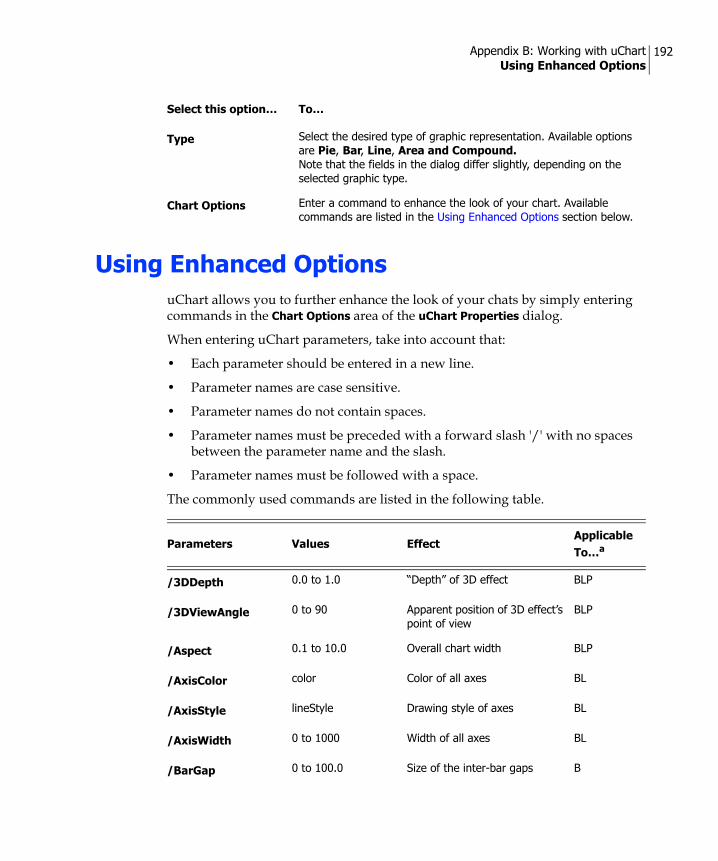
Appendix B: Working with uChart Using Enhanced Options
192
Using Enhanced OptionsuChart allows you to further enhance the look of your chats by simply entering commands in the Chart Options area of the uChart Properties dialog.
When entering uChart parameters, take into account that:
• Each parameter should be entered in a new line.
• Parameter names are case sensitive.
• Parameter names do not contain spaces.
• Parameter names must be preceded with a forward slash '/' with no spaces between the parameter name and the slash.
• Parameter names must be followed with a space.
The commonly used commands are listed in the following table.
Chart Options Enter a command to enhance the look of your chart. Available commands are listed in the Using Enhanced Options section below.
Select this option… To…
Type Select the desired type of graphic representation. Available options are Pie, Bar, Line, Area and Compound. Note that the fields in the dialog differ slightly, depending on the selected graphic type.
Parameters Values EffectApplicable To…a
/3DDepth 0.0 to 1.0 “Depth” of 3D effect BLP
/3DViewAngle 0 to 90 Apparent position of 3D effect’s point of view
BLP
/Aspect 0.1 to 10.0 Overall chart width BLP
/AxisColor color Color of all axes BL
/AxisStyle lineStyle Drawing style of axes BL
/AxisWidth 0 to 1000 Width of all axes BL
/BarGap 0 to 100.0 Size of the inter-bar gaps B

Appendix B: Working with uChart Using Enhanced Options
193
/CalloutLayout Around, Side Layout of pie chart’s callout lines
P
/CalloutLineColor color Color of callout lines P
/CalloutLineLength 0.04 to 1.0 Callout line length P
/CalloutLineStyle llineStyle Style of callout lines P
/CalloutLineWidth 0 to 9999 Width of callout lines P
/ChartLabelSize 0.1 to 100 On-chart value text size BLP
/ChartValueSize 0.1 to 1000 On-chart value text size BLP
/ColorListLabels [ (label1)... (labelN) ] Drawing color for specific labels BLP
/CompressHighLow No, Yes Compress out bottom space BL
/CutoutText No, Yes “Cut out” text from surroundings
BLP
/FillBelow No, Yes Fill in space below data line L
/FloorSize 0.1 to 100 Font height of Floor text BL
/GridLineColor color Color of grid BL
/GridLineStyle lineStyle Drawing style of grid lines BL
/GridLineWidth 0 to 1000.0 Width of grid lines BL
/GroupGap 0 to 10.0 Inter-group space BL
/GroupSize 0.1 to 100 Font height of Group text BL
/HighValue number Top of range for data values BL
/KeepZeroData Yes, No Discard 0-valued data BLP
/LabelColor color Color of labels BLP
/LabelFormat ( stringFormat ) Transforms label text BLP
Parameters Values EffectApplicable To…a

Appendix B: Working with uChart Using Enhanced Options
194
/LabelLocation location On-chart label-value location BL
/LabelLocation location On-chart label-value location P
/LabelOverflow Ignore,... Clipping of on-chart labels that are too long
BLP
/Layer Begin layer data; Separates layers
B
/Layering Overlay, Group, Interleave Grouping of data layers BL
/LayerLabel ( text ) LayerLabel text for layers BL
/LayerLabelFormat ( stringFormat ) Transforms /LayerLabel text BL
/LayerLabelLocation
location Location of /LayerLabel BL
/LeftGap 1.0 to 10.0 Gap width before left most column
BL
/LeftScaleFormat (numberFormat ) Formatting of scale numbers BL
/LeftScaleSize 0.1 to 100 Font height of scale numbers BL
/LeftTextLimit 1000.0 to 1000.0 Left most limit for text BLP
/LegendOutlineWidth
0 to 10.0 Width of spots’ outlines in legend
BLP
/LegendOverflow Ignore,... Clipping of chart legends that are too long
BLP
/LegendPosition 1.0 to 10.0 Shifts legend to right BLP
/LegendSize 0.1 to 100 Size of Legend spot and text BLP
/LineFromOrigin No, Yes Draws an initial line L
/LowValue number Bottom of range BL
/MarkerColor color Color of data point markers L
Parameters Values EffectApplicable To…a

Appendix B: Working with uChart Using Enhanced Options
195
/MarkerShape shape Shape of data point markers L
/MarkerSize 0 to 9999 Size of data point markers L
/MaxGridDivisions 1 to 10 Max number vertical divisions BL
/MergeLabels No, Yes Merge same-label data BLP
/NegativeColor color Color of negative data BLP
/OutlineColor color Color of edging lines BLP
/OutlineStyle lineStyle Drawing style of lines/edging BLP
/OutlineWidth 0 to 1000.0 Width of edging BLP
/PieType FullPie, HalfPieUp, HalfPieDown
Overall shape of pie charts P
/PieValueInPercent Yes, No, or 0 to 5 Print pie data as %; force total = 100% (int)
P
/PrintBottomAxis Yes, No Show/hide zero-axis BL
/PrintBottomTics No, Yes, IfLabel Print tic marks on bottom BL
/PrintCalloutLine IfNeeded, No, Yes Print callout lines P
/PrintFloor No, Yes Show/hide line below axis BL
/PrintGrid Yes, No Show/hide grid lines BL
/PrintLabel Yes, No, ExceptPlaceholder
Show/hide data labels BLP
/PrintLeftAxis Yes, No Show/hide left vertical axis BL
/PrintLeftScale Yes, No Show/hides left scale numbers BL
/PrintLeftTics Yes, No Show/hide left “tic” marks BL
/PrintValue Yes, No Show/hide data labels BLP
Parameters Values EffectApplicable To…a
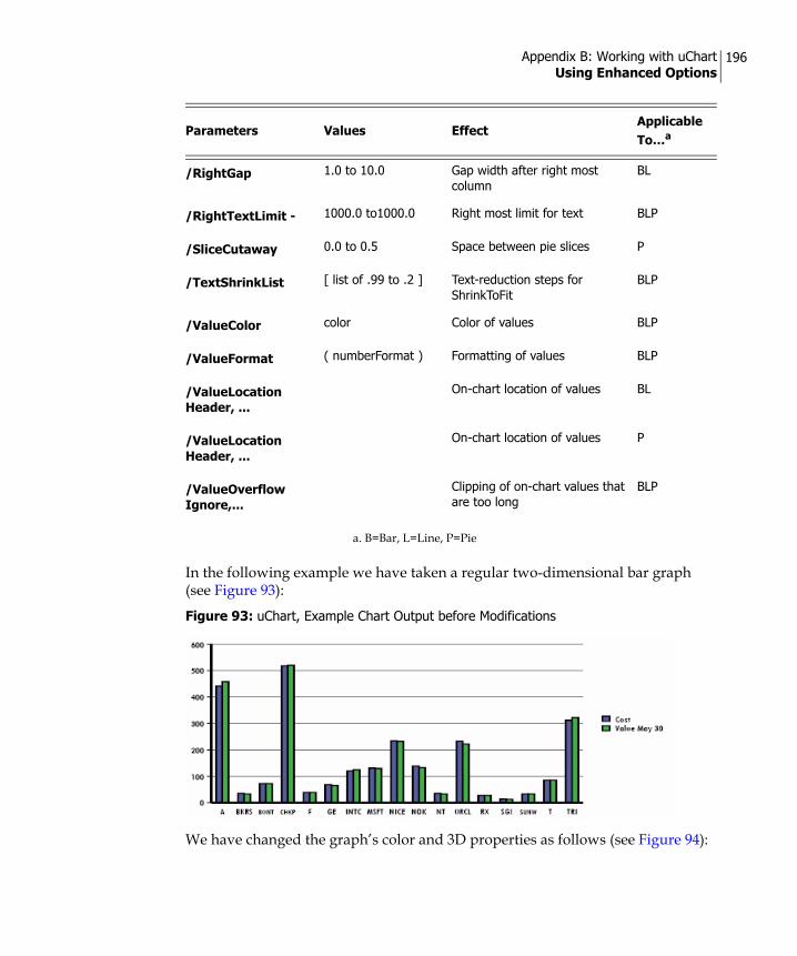
Appendix B: Working with uChart Using Enhanced Options
196
In the following example we have taken a regular two-dimensional bar graph (see Figure 93):
We have changed the graph’s color and 3D properties as follows (see Figure 94):
/RightGap 1.0 to 10.0 Gap width after right most column
BL
/RightTextLimit - 1000.0 to1000.0 Right most limit for text BLP
/SliceCutaway 0.0 to 0.5 Space between pie slices P
/TextShrinkList [ list of .99 to .2 ] Text-reduction steps for ShrinkToFit
BLP
/ValueColor color Color of values BLP
/ValueFormat ( numberFormat ) Formatting of values BLP
/ValueLocation Header, ...
On-chart location of values BL
/ValueLocation Header, ...
On-chart location of values P
/ValueOverflow Ignore,...
Clipping of on-chart values that are too long
BLP
a. B=Bar, L=Line, P=Pie
Figure 93: uChart, Example Chart Output before Modifications
Parameters Values EffectApplicable To…a

Appendix B: Working with uChart Using Enhanced Options
197
1. We first enabled three dimensional view by issuing the command '/3D Yes'.
2. Next, we have set the “depth” of the 3D effect to 30 degrees (/3DViewAngle 30) and the apparent position of the 3D effect’s point of view to '1' (/3DDepth 1).
3. Finally, we have changed the color of the chart's grid from black to red (/GridLineColor Red). The resulting bar graph is shown in Figure 95 on page 197.
Figure 94: uChart Enhanced Chart Options
Figure 95: uChart, Example Chart Output after Modifications
Appendix C
Specialty ImagingThe Xerox FreeFlow DocuSP supports exclusive imaging capabilities with Specialty Imaging text effects and color swatches. This option is available only in the VIPP output format.
uDirect supports two Specialty Imaging effects for the VIPP output format:
1. FluorescentText™—used for printing invisible text on special background color. FluorescentText requires special light to detect the text. This effect prints text in such a way that the content is virtually invisible under normal light conditions, but becomes visible under Ultra Violet (UV) light. Fluorescent marks can provide an added layer of protection against document fraud for applications such as:
Concert ticketsAdmission passesVIP eventsRetail promotions
2. MicroText Mark™—used for printing text in very small font sizes, normally less than one point. The text can be viewed only with a magnifying device. MicroText fonts can provide additional, hidden information for applications such as:
InvoicesCouponsOther fraud-sensitive applications
The Specialty Imaging effect is defined in uDirect using an InDesign Text Box object, such as the effect container. The actual production is performed in either uDirect or uProduce.
The following section explains how to apply a Specialty Imaging effect to an InDesign text box.

Appendix C: Specialty Imaging Defining a Specialty Imaging Effect
199
Defining a Specialty Imaging EffectTo define a Specialty Imaging effect:
1. Left-click anywhere inside the desired text box using the Selection Tool ( ) aand then choose one of the following:
On a Windows machine, right-click to display the context menu.On the Mac, use cmd-click to show the context menu.
2. Select Specialty Imaging from the context menu.The Specialty Imaging dialog is displayed (Figure 96).
3. Select the Enable Specialty Imaging check box.
4. Select the required Specialty Imaging effect from the Effect drop-down list. Available effects are FlourescentText and MicroText Mark.
5. You are required to set an additional parameter, Color or Font, depending on the selected effect:
For FluorescentText, select a color from the Color drop-down list.
For MicroText Mark, select a font from the Font drop-down list.A preview of the selected effect is displayed in the Preview pane.
Figure 96: Specialty Imaging Dialog
Note: A recommended option for viewing text exclusively in UV lighting is the “SI_UV_GOLD1” color with the “Impact” font (16 points).

Appendix C: Specialty Imaging Defining a Specialty Imaging Effect
200
6. Click OK to save your changes.A confirmation message is displayed, describing the expected results of applying the effect.
7. Click OK to confirm.
8. The text frame content in the Document changes to reflect the selected effect, as follows (see Figure 97):
FluorescentText—the text color is changed to [Paper] and the text box’s background color is changed to a swatch color that represents the selected UV effect.MicroText Mark—the text color is changed to Black, the font is changed according to the selected MicroText font and the font size is set to 1 pt. Note that reading the text requires zooming-in.
Note: The following InDesign features are partially supported or unsupported:• MicroText Mark font sets support only upper case characters.• Rotation is unsupported. • Scaling is not supported.
Figure 97: Specialty Imaging Effects as Displayed in an InDesign Document

Appendix C: Specialty Imaging System Requirements for Specialty Imaging Printing (VIPP Only)
201
System Requirements for Specialty Imaging Printing (VIPP Only)
Specialty Imaging printing requires the following:
• FreeFlow Print Server (DocuSP) controller
• VI Interpreter version 7.0 or higher for full usage (version 6.0.1 supports a subset of the Specialty Imaging effects. For more details, please contact your Xerox representative).
FluorescentMarks-Specific RequirementsIn addition to the above System Requirements for Specialty Imaging Printing (VIPP Only), FluorescentMarks require the following:
• Xerox DC5000/6000/7000/8000 family and iGen3 Color Digital printers
• FluorescentMarks-enabled VI interpreter
MicroText-Specific RequirementsIn addition to the above System Requirements for Specialty Imaging Printing (VIPP Only), FluorescentMarks require the following:
• VIPP-enabled Xerox Digital Printers
• MicroFonts purchased from Xerox, and installed on the FreeFlow. Fonts may be purchased online at the Xerox eStore: http://buy.xerox.com/catalog.aspx?cid=6
Note: The FluorescentMark effect is installed with the VI interpreter, but in a disabled state (for details on enabling FluorescentMark with the VI Interpreter, please contact your Xerox representative).

Appendix D
XLIM CapabilitiesXLIM (pronounced: “slim”) is an acronym that stands for XMPie “Less is More”. This composition technology from XMPie significantly increases the speed of generating Print Output files for graphically simple (print) designs. Such designs are exported by uDirect as ".xlim" files and can be uploaded to a uProduce Campaign. uProduce includes the algorithms that process XLIM Dynamic Documents to generate print streams in an extremely speedy and efficient way.
This section provides a complete description of XLIM capabilities:
• Production on page 202
• Page Elements on page 203
• Image Content on page 204
• uChart Dynamic Charts on page 205
• Text Content on page 206
• Inline Content on page 207
• Lines on page 207
• Support for All InDesign Static Object Features on page 207
• Usability Guidelines on page 208
Production
Output FormatsThe XLIM Composition Engine supports the following output formats:
• PostScript
• VPS, external reference for images (Asset Resources)
• VIPP, external reference for images (Asset Resources)
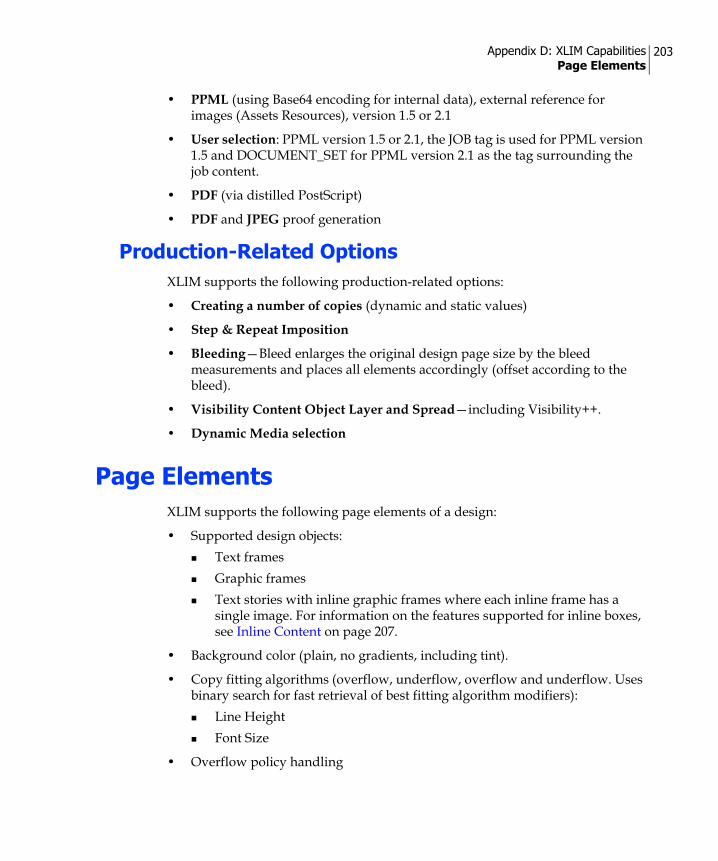
Appendix D: XLIM Capabilities Page Elements
203
• PPML (using Base64 encoding for internal data), external reference for images (Assets Resources), version 1.5 or 2.1
• User selection: PPML version 1.5 or 2.1, the JOB tag is used for PPML version 1.5 and DOCUMENT_SET for PPML version 2.1 as the tag surrounding the job content.
• PDF (via distilled PostScript)
• PDF and JPEG proof generation
Production-Related OptionsXLIM supports the following production-related options:
• Creating a number of copies (dynamic and static values)
• Step & Repeat Imposition
• Bleeding—Bleed enlarges the original design page size by the bleed measurements and places all elements accordingly (offset according to the bleed).
• Visibility Content Object Layer and Spread—including Visibility++.
• Dynamic Media selection
Page ElementsXLIM supports the following page elements of a design:
• Supported design objects:Text framesGraphic framesText stories with inline graphic frames where each inline frame has a single image. For information on the features supported for inline boxes, see Inline Content on page 207.
• Background color (plain, no gradients, including tint).
• Copy fitting algorithms (overflow, underflow, overflow and underflow. Uses binary search for fast retrieval of best fitting algorithm modifiers):
Line HeightFont Size
• Overflow policy handling
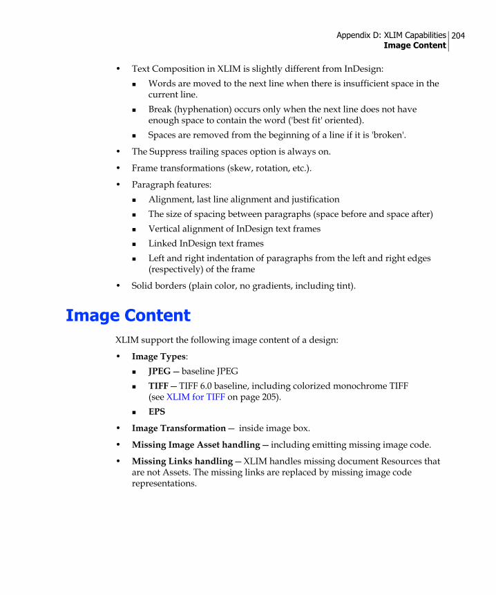
Appendix D: XLIM Capabilities Image Content
204
• Text Composition in XLIM is slightly different from InDesign:Words are moved to the next line when there is insufficient space in the current line.Break (hyphenation) occurs only when the next line does not have enough space to contain the word ('best fit' oriented).Spaces are removed from the beginning of a line if it is 'broken'.
• The Suppress trailing spaces option is always on.
• Frame transformations (skew, rotation, etc.).
• Paragraph features: Alignment, last line alignment and justificationThe size of spacing between paragraphs (space before and space after)Vertical alignment of InDesign text framesLinked InDesign text framesLeft and right indentation of paragraphs from the left and right edges (respectively) of the frame
• Solid borders (plain color, no gradients, including tint).
Image ContentXLIM support the following image content of a design:
• Image Types:JPEG — baseline JPEGTIFF — TIFF 6.0 baseline, including colorized monochrome TIFF (see XLIM for TIFF on page 205).EPS
• Image Transformation — inside image box.
• Missing Image Asset handling — including emitting missing image code.
• Missing Links handling — XLIM handles missing document Resources that are not Assets. The missing links are replaced by missing image code representations.

Appendix D: XLIM Capabilities uChart Dynamic Charts
205
uChart Dynamic ChartsXMPie uChart is used to generate dynamic chart images in an InDesign document. Starting with PersonalEffect version 4.5, you can produce dynamic chart images in a XLIM production.
The following limitations apply:
• uChart is not supported when generating JPG images in a XLIM production.
• It is not possible to display, add or edit uChart graphs in uEdit. InDesign Graphic boxes that contain uChart graphs are locked for editing. These boxes remain unchanged in the XLIM document and are processed normally during a XLIM production in uProduce.
XLIM for TIFFXLIM support for TIFF images closely follows the TIFF 6.0 Baseline specification, while adding features from the rest of the TIFF 6.0 specifications (mainly CMYK support).
The supported features include:
• 1-Bit TIFF/Bi-level: '1' value bits appear with the color applied in InDesign.'0' value bits are transparent (mask).
• Grayscale, CMYK and RGB (no colorimetric data support, both full RGB and Palette RGB) images.
• Grayscale images will use the box and image applied background colors in InDesign to define their color, and will refer to the image data to define the specific pixel percentage of that color. Real grayscale may be achieved by setting the image foreground color to black, and the box background to white (which are the defaults).
• Images must be stripped (not tiled). Single or multiple strips are supported.
• If there is no resolution information, the image will use InDesign logic to appear the same.
• Supported compressions (with reference to relevant image information) are as follows: uncompressed, CCITT G3/G4, LZW and PackBits.
• FillOrder 1 and 2 are supported.

Appendix D: XLIM Capabilities Text Content
206
• There should be a single image in a file (if not, only the first image is used).
• Transparency information (associated and unassociated alpha) is not supported and will create corrupted output as the alpha bits are not ignored.
Text ContentXLIM supports the following text content and attributes of a design:
• Foreground color (plain color, no gradients, including tint).
• Font types: OTF, TTF, Type 1 (same as uProduce) and unicode fonts (including Symbol).
• Text File Content Objects — plain text (that is, *.txt file containing strings only) and XNIP files (*.xnip).
• Missing text Assets handling (including emitting missing text code).
• Subscript and superscript — the parameters for subscript and superscript are defined in the document level.
• 'Indent to here' character
• Bullets and numbering — with the following limitataions:Bullet font is ignored — the paragraph font overrides any special font attributes of the list’s bullets or numbers.The bullets and numbering definition supports only the following special characters:
^# — current number in current level^1-^9 — current number in specified level^t — tab, consistent with tab support in XLIM
Bullet alignment is ignored."List" options are ignored — you cannot continue bulleted and numbered lists over different text stories, whether these stories are in the same document or in different documents.
Note: XNIP files are not supported by uEdit.
Note: The InDesign bullets and numbering feature is supported in XLIM productions using uProduce as well as in uEdit applications.

Appendix D: XLIM Capabilities Inline Content
207
Inline ContentXLIM supports the following inline content of a design:
• Images — the supported inline box content is images only (meaning, no text in inline box, no background, etc.).
• Image features — all image features described in Image Content (see page 204) are supported when inline.
• border and fill are supported for inline boxes.
LinesXLIM supports the following line properties of a design:
• Straight lines — two points in path.
• Color — plain color, no gradients, including tint.
Support for All InDesign Static Object Features
Starting from PersonalEffect version 4.5, all InDesign features of static objects (that is, design objects that are not tagged with Content Objects) are fully supported.
XLIM production offers extended capabilities in rendering unsupported InDesign objects, by converting static design objects to EPS images. An EPS image that is produced in that process is common to all recipients; therefore, it cannot contain dynamic content.
XLIM does not convert design objects that include missing fonts or whose attribute is set to 'nonprinting'.
EPS images of converted InDesign objects are stored in a designated folder, in the same location as the XLIM file. The folder name has the following format:
<InDesign document name>_Resources
However, converted EPS images that were produced during the packaging of a XLIM Package File (DPKG) or a XLIM Campaign Package File (CPKG) are stored in a different location: the Resources folder of the package file.

Appendix D: XLIM Capabilities Usability Guidelines
208
Usability GuidelinesWhen you produce a XLIM document that contains unsupported design objects, you should take the following issues into consideration:
• Using Transparency on page 208
• Using Text Wrap on page 209
• uEdit on page 210
Using TransparencyXLIM does not support transparency. It merges overlapping transparent objects into a single EPS image.
Figure 98 shows an example of an InDesign document that includes two static boxes (that is, boxes that do not include dynamic content): a transparent box (box A) that is placed over a box filled with a gradient color (box B). Since the two boxes overlap and cannot be rendered separately, XLIM merges them into a single EPS image.
Note that in this example, if either box A or box B contained dynamic content, XLIM would not be able to merge the two boxes and produce the EPS image.
Furthermore, in order to maintain the Z-order of several overlapping objects when one (or more) of them uses transparency, XLIM may convert all overlapping objects into a single EPS image.
Figure 99 shows an example of four overlapping objects: boxes A, B, C and D. The boxes are arranged in a stack, where box A is located at the back and the transparent box D is located at the front. If only boxes A, C and D were converted
Figure 98: XLIM — Using Transparency
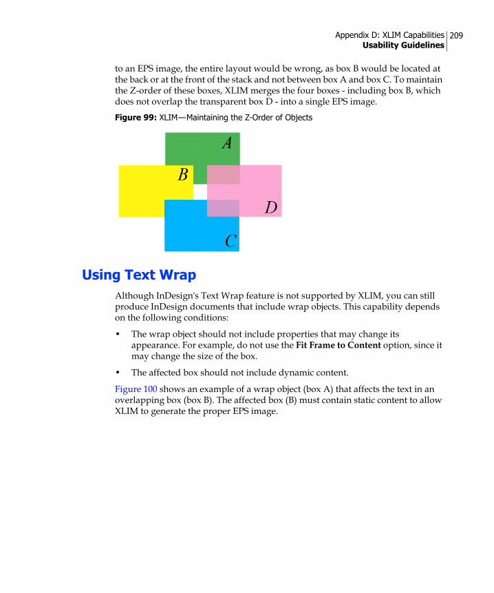
Appendix D: XLIM Capabilities Usability Guidelines
209
to an EPS image, the entire layout would be wrong, as box B would be located at the back or at the front of the stack and not between box A and box C. To maintain the Z-order of these boxes, XLIM merges the four boxes - including box B, which does not overlap the transparent box D - into a single EPS image.
Using Text WrapAlthough InDesign's Text Wrap feature is not supported by XLIM, you can still produce InDesign documents that include wrap objects. This capability depends on the following conditions:
• The wrap object should not include properties that may change its appearance. For example, do not use the Fit Frame to Content option, since it may change the size of the box.
• The affected box should not include dynamic content.
Figure 100 shows an example of a wrap object (box A) that affects the text in an overlapping box (box B). The affected box (B) must contain static content to allow XLIM to generate the proper EPS image.
Figure 99: XLIM — Maintaining the Z-Order of Objects

Appendix D: XLIM Capabilities Usability Guidelines
210
uEdituEdit users should take the following issues into consideration:
• A uEdit object that is created by merging two or more InDesign objects will inherit the Lock attributes of all merged boxes. For example, if the uEdit Lock Option Location is selected for one box and that same option is unselected for another box, the box that is created by merging these two boxes will have that option selected.
• The contents of an InDesign object that was converted to an EPS image cannot be edited in uEdit.
Figure 100: XLIM — Using Text Wrap

Glossary 211
Glossary
The following concepts and terms are used throughout this guide.
ADOR Object—see Content Object.
ADOR technology—stands for Automatic Dynamic Object Replacement (ADOR) technology, which encompasses all of XMPie’s foundation technologies that provide Dynamic Publishing solutions.
Asset Source—in the XMPie context, this term refers to a collection of Campaign Assets (for example, images, formatted text files, etc.) and its location. You can define one or more Asset Sources for a single Campaign.
Assets—in the XMPie context, this term refers to content (such as graphic files and text files) that feeds the Dynamic Objects in a Design (as opposed to Resources, which are static content).
Binding—the integration of Logic, Data and Design into a Dynamic Document. With ADOR technology, binding is automatic.
Business rule—see Rule.
Campaign—a representation of a set of Dynamic Documents, possibly of different types, all sharing the same Plan file, Data Source(s) and Asset Source(s).
Content Object (also known as ADOR Object)—an object of the Plan that is visible to a Design (via the “Link to Plan” operation of uDirect). In uDirect, the Plan is not explicit; it is “behind the scenes” and is automatically created and maintained to reflect linking to Data Sources, adding Content Objects or specifying Rules. Hence, in uDirect Content Objects are visible only through the uDirect Palette.
Content Objects can be of various design-centric types, for example, text, graphic, etc. The designer uses simple point-and-click operations to tag a design object (say, a text frame or graphic frame) with the desired Content Object. Such a tagged design object becomes a Dynamic Object: a design object that derives its content and/or appearance from the Content Object’s value. Content Object values are calculated by the Plan’s Rules, using the given Data Source(s). These calculations are performed iteratively, once for each recipient, resulting in a set of recipient-specific values for each Content Object. In a way, one can think of Content Objects as the intermediaries between the Logic (that is, Plan) and Data (that is, Data Source) and the Design (that is, XMPie tagged document).
Content Samples—a set of possible values, defined by the user, for a given Content Object; different Content Objects can have different sets of values associated with them. There are no constraints on these values; except that they

Glossary 212
need to adhere to the type of Content Object with which they are associated (for example, the Content Samples associated with a Graphic Content Object should be a set of images). For example, one can define three images—”CarA”, “CarB”, and “CarC”—as the possible values of a “CarPitcutre” Graphic Content Object. It is then possible to flip through these Content Samples, to see how the different images appear in the Design, without being forced to rely on a complete Plan or on Proof Sets that may not necessarily be available at the early stages of the design process.
Content source—the source that provides values that feed the Content Objects (via Rules or directly), which in turn change the content (or format) of the Dynamic Objects in your design. There are different types of content sources, including Data Sources, Proof Sets and Content Samples.
Data—one of the Dynamic Document’s basic components. In the XMPie context, the Data component is represented by Data Sources and Asset Sources.
Data Schema—a description of the Data Source structure that is expected by the Logic. The Data Schema specifies the following: the required tables; each table’s column headers (for example, “First Name”, “Customer ID”, etc.) and the type of data they represent (for example, a string, an integer etc.); and the relationship between these tables (for example, a common field).
Data Source—represents the Dynamic Document’s Data component, which is common to all Dynamic Documents in a given Campaign. The schema of the Data Source must adhere to the Data Schema defined by the Campaign's Plan file. Each Campaign may have multiple Data Sources, in any ODBC compliant format (including Oracle, MS-SQL, MySQL, IBM-DB2, CVS, XML and MS Access).
Design (also known as Tagged Documents, Dynamic Document Templates and uProduce Documents)—a document (such as an Adobe InDesign document) that includes regular and tagged design objects. Tagging is performed using the uDirect plug-in of the relevant host application (Adobe InDesign and Adobe Dreamweaver are currently supported).
Document instance—a copy of the Design that was instantiated for a given recipient. A production run of a given Dynamic Document for a batch of, say, 1000 recipients will result in 1000 Document instances.
Dynamic Document—a modular binding of three components: Logic, Data and Design. Practically speaking, these components are represented by a Plan file, a Data Source and a Design (respectively). For uDirect, and explicitly for uDirect Standard, the Plan file is not an object that is visible to the user; however, it is created as the user works with Data Sources and Rules, and is represented internally, as part of the Dynamic Document, by uDirect.
Dynamic Document Template (also known as a Tagged Document)—see Design.

Glossary 213
Dynamic Object—a design object (for example, a text frame or a graphic frame) that is tagged by a Content Object. This tagging transforms the design object from static to dynamic. A Dynamic Object derives its content and/or appearance from the Content Object’s recipient-specific value (as opposed to showing a pre-set, static value).
Dynamic Publishing—a discipline of Publishing that aims to produce any customizable document, in any media, on-demand. Dynamic Publishing extends Variable Data Printing (VDP) into digital print and electronic media, focusing not only on final output media but also on creating documents with dynamic content, from Design to Production.
Logic—the set of Content Objects; the QLingo expressions that compute their values for a given recipient; and the interface to Data. In the uDirect context, the terms “Logic” and “Rules” are interchangeable.
Output Element—a representation of a design element (such as text box, image box, lines and other shapes) in the Print Output file. There are two types of output elements:
• Reusable content—a reusable content is an output element reused within a personalized print job (also known as Recurring content). Typical examples include a logo image, a signature, boilerplate text, etc.
• Unique content—a unique content is an output element that is unique to a record within a personalized print job. Typical examples include text box with the recipient name and/or address, social security number, etc.
In general, all images are classified as Reusable content. However, an image may be considered a Unique content when you apply transparency techniques to the image, which eventually results in utilizing XMPie's X-DOT technology. Transparency techniques are: • Drop shadow
• Feathering
• Opacity lower than 100%
• Transparency (unique to images)
Plan—the encoding of Logic in the Campaign; it is encoded in XML, and stored in files with a “.plan” extension.
In uDirect the Plan is encoded internally, as part of the uDirect Document, thus it is not visible as a separate object.

Glossary 214
The Plan file consists of the following elements:
• A Data Schema, which describes the structure of the Data Source needed to drive the Campaign.
• A set of Content Objects, which can be used for tagging design objects (for example, by using uDirect), thereby transforming them into Dynamic Objects
• A set of Variables, which are similar to Content Objects, except that they cannot be used for tagging design objects (hence, they are internal to the Plan). Their use is for computing intermediate results, and using such values in computing values for Content Objects. For example, a Plan may have a Variable called “discount” that holds the percentage discount one is entitled to, based on the given individual’s purchase history, or affiliation with the Platinum, Gold, or Silver levels of some membership club. This discount Variable can be used to compute the value of a Content Object called, say, “discountAmount”, which will appear in the document, showing the monetary value (as opposed to the percentage value) of a discount that one receives. Variables allow for avoiding repetitive computations or data retrievals, as well as improved readability of the Plan, for later revisions, etc.
• A set of Rules—QLingo or SQL expressions that compute the values of the Plan's Content Objects and Variables, once for each recipient.
In high-level terms, one should think of a Plan as a program that is being repeatedly executed, once for each recipient. In each of these iterations, the Plan performs computations that result in a set of values: one recipient-specific value for each Content Object. The process that “executes” such Plan programs is known as Plan Interpreter, and it is part of uPlan and uProduce.
Print file (also known as Print Stream)—an output file in one of the print or Variable Information (VI, in short) data printing formats (PDF, VPS, PPML, VIPP, PPML/VDX or PostScript), which is further processed by a print controller (that is, RIP). The processing of a print file by a print controller produces a series of hard-copy printed Document Instances, each representing the variations made for a specific individual.
Proof Set—an XML-encoded table where columns represent Content Objects and rows represent a set of values—one for each Content Object—for a given recipient. Proof Sets are generated by uDirect, uCreate Print, uPlan and uProduce. They are typically generated for a subset of the recipients list, with possibly a few more filtering criteria, by executing the Plan for each such selected recipient and storing the resulting Content Object values in that recipient’s row. Sometimes Proof Sets may represent the whole set for which a specific production run is going to be executed. In such cases they may be referred to as Production Sets.
Glossary 215
QLingo—a scripting language developed by XMPie, to allow the use of classical conditional logic—such as 'if-then-else' or 'switch' constructs—in expressions that compute values for Content Objects or Variables in a Plan file. QLingo also supports many domain-specific constructs for formatting, process control, and other data manipulation functions. Together with SQL and the ability to call upon external functions, QLingo makes the Plan file expressions (for example, Rules) extremely powerful, yet not overly complex.
Recipient—the person who receives an individual instance of the Dynamic Document. If the Document is static, all recipients receive identical copies; if the Document is dynamic, each recipient receives a unique Document instance, which has been personalized based on this recipient’s specific data.
Recipient List—a table whose records represent the recipients of a particular Dynamic Document. At production time, a personalized Dynamic Document instance is generated for each recipient (that is, record) in this Recipient List.
Resources—static graphic files, which are used in the design and are fixed throughout production (as opposed to Assets, which change per-recipient). An example may be the company logo.
Rule (also known as business rule)—part of the Logic defined in the Campaign’s Plan file. Rules are expressions that calculate Content Objects’ values for each recipient. Rules can also be added or edited using uDirect’s Rule Editor. In the uDirect context, the terms “Logic” and “Rules” are interchangeable.
Static Document—a regular desktop publishing document, such as an InDesign document.
Tagged Document—see Design.
Variable—an internal object of the Plan, which can be assigned values of expressions (QLingo, SQL, etc.). A Variable can also be used as input for expressions that compute values of Content Objects. Variables allow for avoiding repeat computations or data retrievals, as well as improved readability of the Plan, for later revisions, etc. Variables are not visible to uDirect (hence to the designer).
X-DOT—an acronym that stands for XMPie Dynamic Object Transparency (X-DOT). X-DOT accurately reproduces, by using opaque objects, the visual effect of transparency in print output file formats that do not support live transparency. It creates one 'mega object' out of several 'atomic objects' that need to be combined to preserve the transparency effects between them. Transparency may be created when special effects (such as shadow, feathering or opacity) are used, or in an image file that contains transparency.

Glossary 216
XLIM—an acronym that stands for XMPie “Less is More”. This composition technology from XMPie increases significantly the speed of generating Print Output files for graphically simple (print) Designs. Such Designs are exported by uDirect as ".xlim" files and can be uploaded as such to a uProduce Campaign. uProduce includes the algorithms that process XLIM Dynamic Documents for generating print streams in an extremely speedy and efficient way.

Index 217
Index
Numerics2D Barcode functions 164
customizing parameters 167defining 165valid input data 171XMP2DAztecCode function 173XMP2DDataMatrix function 173XMP2DMaxiCode function 174XMP2DMicroPDF function 174XMP2DPDF417 function 173XMP2DQRCode function 174
AAbort operator 185ABS function 153Adding to InDesign
Graphic Content Object 43Table Content Object 55Text Content Object 42Text File Content Object 43
Adjustfont size 102horizontal scale 102
ADOR Object 211Age function 156Arithmetic Expressions 149AsBoolean function 179AsDate function 179AsNumber function 180Asset 211
folder 119location 118missing 131
Asset Source 211AsString function 180Auto flow 100
options 102Auto leading 100, 103
BBarcode
dynamic 159fonts 161
Barcode functions2D 164Linear 158
Bleed values 135Boolean Literals 148
Literal Constants 148
CCache element locally 104Call operator 186Campaign packages 120Ceil function 153Center in frame 104Clear Global Cache 23Clearing
content samples 22Comparisons 150Compress output 130Conditions
Rule 64Constants
Environment 181Logical 148
Content Objectdata column 17, 29, 30deleting 29, 96duplicating 29, 96editing 145Graphic 19list 16properties 62renaming 95Rule 25Rule Editor 145

Index 218
Style 19text properties 98, 99type 19, 95uImage 75Visibility 19
Content Samples 116clearing 22
Context menu 29Control Statements 151
If/Else 151Switch 152
Conversion functions 179AsBoolean 179AsDate 179AsNumber 180AsString 180
Copy fitting 100overflow 77underflow 77
CounterData Source 28linking to 21
Current Record Number function 181Cut and stack 133Cut marks 133
DData Source
linking to 21Date functions 154
Age 156FormatDate 157GetDay 154GetDayofWeek 155GetHour 155GetMinute 156GetMonth 155GetSecond 156GetYear 155Now 156
Date Literals 147Literal Constants 147
DocumentPackage 120Static 215static 215
Document Type function 184Duplex printing 133Dynamic barcode 159dynamic graphic properties 103Dynamic print 24Dynamic properties 98
story 99text 98, 99
Dynamic story handling 101Dynamic table 55
EEditing
Plan file 21, 39Embed
Assets 135fonts 135Resources 135
Environment constants 181Error policies 131Exchange export 23
XLIM 120Expressions
arithmetic 149
FFile exchange 144Find and Replace 22Find function 178FindAndReplace function 178Fit frame to contents 104Fit proportionally 104Fit to frame 104Floor function 153Font
adjust size 102missing 131

Index 219
FormatDate function 157FormatNumber function 153Functions 153
Date functions 154Age 156FormatDate 157GetDay 154GetDayofWeek 155GetHour 155GetMinute 156GetMonth 155GetSecond 156GetYear 155Now 156
Linear Barcode functionsXMPBarCode128 162XMPCODABAR 162XMPCode39 163XMPEAN13 163XMPEAN8 163XMPInt2Of5 163XMPMSI 163XMPOneCode 164XMPPOSTNET (USPSZIP) 164XMPUPCA 164XMPUPCE 164
Numeric functions 153ABS 153Ceil 153Floor 153FormatNumber 153Rand 154Round 154
GGap between logical pages 133GetDay function 154GetDayofWeek function 155
GetEnv functions 181Current Record Number 181Document Type 184Host Application function 182HTML Media 181Job Type 183Print Media 181Proof Set 181Text Media 182
GetHour function 155GetMinute function 156GetMonth function 155GetSecond function 156GetYear function 155Global Cache
clear 23clearing 23using 135
GraphicContent Object 19
HHelp
User Guide 24Highlight Dynamic Objects 42Horizontal scale 102HTML Media function 181
IIf/Else Statements 151Image
Specialty Imaging 198Importing Rules 94IsFileExist function 187
JJob Type function 183
KKey 67
Index 220
LLCase function 175Length function 176Linear Barcode functions 158
XMPBarCode128 162XMPCODABAR 162XMPCode39 163XMPEAN13 163XMPEAN8 163XMPInt2Of5 163XMPMSI 163XMPOneCode 164XMPPOSTNET (USPSZIP) 164XMPUPCA 164XMPUPCE 164
Linkingcounter 21Data Source 21Document to Plan 21, 39Plan file 21Proof Set 21
Literal Constants 146Boolean Literals 148Date Literals 147Null Constant 148Number Literals 147String Literals 146
LiteralsDate 147number 147string 146
Logical Constants 148Logical Expressions 150logical pages 133Lower case formatting 175LTrim function 177
MMaintain transformation 104Media selection 137Miscellaneous operators and functions
Abort operator 185
Call operator 186IsFileExist function 187ReportMessage function 185Skip operator 186
Mold row 57
NNow function 156Null Constant 148Null Literals
Literal Constants 148Number Literals 147Numeric functions 153
ABS 153Ceil 153Floor 153FormatNumber 153Rand 154Round 154
OOptions menu 20Output element
definition 213Overflow 99, 100, 102
PPage dimensions 133Palette 14
data column 17Personalization 213Plan
editing 21, 39linking to 21, 39reloading 21, 40
plug-in 1PPML
adding metadata to each record 136embed Assets or Resources 135extract all content to external files

Index 221
135extract unique content to external
files 135tagging each record as a document
group 136tagging fixed background as a
master page 136Preflight 23Primary field 28, 67Print file 214Print Media function 181Print Output file 128Print to file 128Production Sets 111Proof Set
creating 113exporting 23funcion 181linking to 21loading 115viewing 21
Proof Set function 181Proofing 113Proportional & centered 104
QQLingo 145, 215
Arithmetic Expressions 149Barcode functions
2D 164Comparisons 150Control Statements 151
If/Else 151Switch 152
Conversion functions 179AsBoolean 179AsDate 179AsNumber 180AsString 180
Functions 153Date functions 154
Numeric functions 153GetEnv functions 181Linear Barcode functions 158Literal Constants 146
Boolean Literals 148Date Literals 147Null Constant 148Number Literals 147String Literals 146
Logical Expressions 150Miscellaneous operators and
functions 185Recipient Information Field Reference
187String functions 175
find 178FindAndReplace 178LCase 175Length 176LTrim 177Replace 178RTrim 178SubString 176TCase 176Trim 177UCase 176
RRand function 154Random integer 154Recipient 215Recipient Information Field Reference 187Reloading
Plan 21, 40Replace function 178ReportMessage function 185Resources 215Round function 154
Index 222
Rounding numbers 154RTrim function 178Rule 25, 60
Conditions 64defining 65Functions 64Values 64
Rule Editor 60, 145Rules
examples 65importing 94
SSample data 113, 115Scale
horizontal 102Set Assets folder 22Skip operator 186Specialty Imaging 198Static Document 215Static document 215Step & Repeat 132step & repeat 134Story properties 99String functions
Find 178FindAndReplace 178LCase 175Length 176LTrim 177Replace 178RTrim 178SubString 176TCase 176Trim 177UCase 176
String Literals 146Style
Content Object 19, 63SubString function 176Suppress Trailing Spaces on Empty Content 100
Switch Statement 152
TTable
Content Object 19, 55Dynamic 55
TCase function 176Text Content Object
Rule 63Text File
Content Object 19Text Media function 182Title style formatting 176Transformation 104Trim function 177Type
changing 95Content Object 19
UUCase function 176uChart 188uDirect Designer 3uDirect Professional 3
overview 3uDirect Standard
overview 1uEdit 107
Lock options 107Permissions 107
uImageAssets 92Data 78Defaults 22Graphic Content Object 75output filename format 80Tag 72, 83Template 72
Underflow 99, 102Upper case formatting 176Use Global Caching 135

Index 223
VVDX
tagging fixed background as a master page 136
VI print formatSee Variable Information print
formatViewing
Proof Sets 21VIPP
embed Assets or Resources 135extract reusable content to external
files 135extract unique content to external
files 135Output files
project name 135Visibility 51
Content Object 19Content Object Rule 63icons 16
VPSembed Assets or Resources 135extract unique content to external
files 135
WWYSIWYG viewing 110
XX-DOT 105
definition 215XLIM 107
capabilities 202definition 216design mode 23evaluate 22exchange export 120
XMP2DAztecCode function 173XMP2DDataMatrix function 173XMP2DMaxiCode function 174
XMP2DMicroPDF function 174XMP2DPDF417 function 173XMP2DQRCode function 174XMPBarCode128 function 162XMPCODABAR function 162XMPCode39 function 163XMPEAN13 function 163XMPEAN8 function 163XMPInt2Of5 function 163XMPMSI function 163XMPOneCode function 164XMPPOSTNET (USPSZIP) function 164XMPUPCA function 164XMPUPCE function 164