Embed Size (px)
Citation preview

Helium Operator Manual (CLI)
S . W o n g
D e c e m b e r 2 0 1 1

1 GLOSSARY Acronym Meaning Comments
ACS Auto Configuration Server ADSL Asymmetric Digital Subscriber Line AES Advanced Encryption Standard CBR Constant Bit Rate CLI Command Line Interface CPE Customer Premises Equipment DHCP Dynamic Host Configuration Protocol DNS Domain Name System DSCP Differentiated Services Code Point DSLAM Digital Subscriber Line Access Multiplexer DTMF Dual-Tone Multi-Frequency ECN Explicit Congestion Notification EF Expedited Forwarding FTP File Transfer Protocol FXO Foreign eXchange Office FXS Foreign eXchange Subscriber Subscriber connection port HTTP HyperText Transfer Protocol ICMP Internet Control Message Protocol IP Internet Protocol LAN Local Area Network LCP Link Control Protocol LLC Logical Link Control MGCP Media Gateway Control Protocol PHB Per-Hop Behaviour The policy and priority applied to a packet
when traversing a hop in a DiffServ network PPP Point-to-Point Protocol PPPoE Point-to-Point Protocol over Ethernet QoS Quality of Service RTP Real Time Protocol SIP Session Initiation Protocol SSID Service Set Identifier Wireless network name TKIP Temporal Key Integrity Protocol ToS Type of Service UBR Unsustainable Bit Rate USB Universal Serial Bus VBR Variable Bit Rate VoIP Voice over IP WAN Wide Area Network WPA Wireless Protected Access WIFI encryption WPS Wireless Protected Setup Easy wireless setup by a button VDSL Very High-Speed Digital Subscriber Line

2 REFERENCES
Function Document reference Comments
ebtables http://ebtables.sourceforge.net/br_fw_ia/br_fw_ia.html filtering tool for a Linux-based bridging firewallDSCP et ToS http://www.cisco.com/en/US/tech/tk543/tk757/technologies_te
ch_note09186a00800949f2.shtml
TR069 http://www.broadband-forum.org/technical/download/TR-069_Amendment-2.pdf
Tcpdump http://www.tcpdump.org/tcpdump_man.html

Table of contents
1 Glossary .................................................................................. 2
2 References .............................................................................. 3
3 Configuring the CPE .............................................................. 6
3.1 Changing the configuration ............................................................................. 6 3.2 Saving and restoring a configuration ............................................................. 8
4 Local Area Network (LAN) ..................................................... 9
5 WiFi interface configuration .................................................. 9
5.1 Overview of WiFi encryptions .......................................................................... 9 5.2 General settings .............................................................................................. 10 5.3 Encryption mode ............................................................................................. 10
6 Wide Area Network (WAN) – Layer 2 .................................. 11
6.1 ATM configuration .......................................................................................... 11
7 Wide Area Network (WAN) – Layer 3 .................................. 12
7.1 PPP Connection .............................................................................................. 12 7.2 IP Connection (Static or DHCP) ..................................................................... 12 7.3 Incoming open ports ...................................................................................... 12
8 Voice over IP (VoIP) ............................................................. 13
8.1 Global settings ................................................................................................ 13 8.2 VoIP account ................................................................................................... 13 8.3 Added-value services ..................................................................................... 14
9 Firewall .................................................................................. 15
9.1 Filtering by logical interface .......................................................................... 15 9.2 Filtering by IP addresses or ports ................................................................. 15 9.3 Filtering by other criteria ................................................................................ 15 9.4 After filtering ................................................................................................... 15
10 QoS ...................................................................................... 16
10.1 Linux Classes and Queues ......................................................................... 16 10.2 Configure QoS ............................................................................................. 17 10.3 VoIP Traffic ................................................................................................... 18 10.4 Other traffic .................................................................................................. 19
11 Provisioning & Remote Management .............................. 20
11.1 TR-069........................................................................................................... 20 11.2 FTP or HTTP Provisioning .......................................................................... 21
12 IGMP management ............................................................. 23
12.1 IGMP snooping ............................................................................................ 23 12.2 IGMP proxy ................................................................................................... 23
13 Annex: Configuration examples ....................................... 24
A.1 Bridging an Ethernet port on a WAN interface ............................................. 24

A.2 Trunking configuration ................................................................................... 25
14 Annex: Troubleshooting ................................................... 27
A.3 “logread -f” ...................................................................................................... 27 A.4 TCPDUMP ........................................................................................................ 27 A.5 Command “ifconfig” ....................................................................................... 28 A.6 Command “adslinfo” ...................................................................................... 28

3 CONFIGURING THE CPE
Note that all parameters can be customized regarding the customer requirements.
3.1 CHANGING THE CONFIGURATION This chapter shows you how to change some parameters of the configuration through the CLI.
First of all, open a Telnet session on the CPE and log with credentials root/hemingway.
Before using all commands listed below, you should first type this cli, in order to enter command line mode.
home login: root Password: ~# cli >
3.1.1 MAIN COMMANDS
The main commands you can use are:
cd directory Go to the directory
cd ._ Go to the parent directory
cd _ Go to the root directory
ls List the parameters in the current directory with their current value
ln Show the values which can be used for the parameters
set parameter value Set the parameter with this value
mk number Create a new set of parameters in an array with the index number
rm number Delete the set of parameters in array with the index number
fdump diff Show the differences between the default configuration and the current one
applydiff Apply differences between two configuration versions
fcommit Commit all changes
3.1.2 CHANGING THE PARAMETERS
In the configuration, each ‘_’ (underscore) stands for a move of directory or the parameter in the directory. Here is an example:
LANDevice_1_IPInterface_1_Enable=1
This can be done in CLI as followed:
> cd LANDevice LANDevice > cd 1 LANDevice_1 > cd IPInterface LANDevice_1_IPInterface > cd 1 LANDevice_1_IPInterface_1 > set Enable 1
Or also directly:
> cd LANDevice_1_IPInterface_1 LANDevice_1_IPInterface_1 > set Enable 1

3.1.3 MODIFYING AN ARRAY
To create a set of parameters in an array, do the following.
First, list the current existing sets in the array:
WANConnectionDevice_1_Service > ls [33] WANConnectionDevice_1_Service_List = [1] [ 0] WANConnectionDevice_1_Service_1_Enable = [0] [ 9] WANConnectionDevice_1_Service_1_RemotePort = [] [ 9] WANConnectionDevice_1_Service_1_Port = [] [ 2] WANConnectionDevice_1_Service_1_Protocol = [] [ 2] WANConnectionDevice_1_Service_1_UniqueKey = []
Then create the next set of parameters:
WANConnectionDevice_1_Service > mk 2
Set the parameters as expected:
WANConnectionDevice_1_Service_2 > set Port 80 WANConnectionDevice_1_Service_2 > set RemotePort 80 WANConnectionDevice_1_Service_2 > set Protocol tcp WANConnectionDevice_1_Service_2 > set UniqueKey http WANConnectionDevice_1_Service_2 > set Enable 1
List all the parameters to double-check:
WANConnectionDevice_1_Service_2 > cd ._ WANConnectionDevice_1_Service > ls [33] WANConnectionDevice_1_Service_List = [1,2] [ 0] WANConnectionDevice_1_Service_1_Enable = [0] [ 9] WANConnectionDevice_1_Service_1_RemotePort = [] [ 9] WANConnectionDevice_1_Service_1_Port = [] [ 2] WANConnectionDevice_1_Service_1_Protocol = [] [ 2] WANConnectionDevice_1_Service_1_UniqueKey = [] [ 0] WANConnectionDevice_1_Service_2_Enable = [1] [ 9] WANConnectionDevice_1_Service_2_RemotePort = [80] [ 9] WANConnectionDevice_1_Service_2_Port = [80] [ 2] WANConnectionDevice_1_Service_2_Protocol = [tcp] [ 2] WANConnectionDevice_1_Service_2_UniqueKey = [http]
To remove a set of parameters:
WANConnectionDevice_1_Service > rm 2 WANConnectionDevice_1_Service > ls [33] WANConnectionDevice_1_Service_List = [1] [ 0] WANConnectionDevice_1_Service_1_Enable = [0] [ 9] WANConnectionDevice_1_Service_1_RemotePort = [] [ 9] WANConnectionDevice_1_Service_1_Port = [] [ 2] WANConnectionDevice_1_Service_1_Protocol = [] [ 2] WANConnectionDevice_1_Service_1_UniqueKey = []
3.1.4 COMMITTING THE CHANGES
When all the changes are done, you must apply them with fcommit command:
> fcommit /etc/init.d/fwservices restart 1 /etc/init.d/firewall restart 1 /etc/init.d/iptables restart

3.2 SAVING AND RESTORING A CONFIGURATION When many changes are made in the configuration, it should be a good idea to reproduce the configuration on another CPE or save the configuration in case of a factory reboot of the CPE.
3.2.1 SAVING
To save the configuration, you have to execute the fdump diff command, which displays the differences between the current configuration and the default one. Here is an example:
> fdump diff ‐ Voice_WANInterface=5 ‐ LANDevice_2_Enable=1 + WANConnectionDevice_1_Service_3_UniqueKey='sip' + WANConnectionDevice_1_Service_3_Protocol='udp' + WANConnectionDevice_1_Service_3_Port=5060 + WANConnectionDevice_1_Service_3_Enable=1 ‐ WANConnectionDevice_1_Service_List=1,2 + WANConnectionDevice_1_Service_List=1,2,3 + WANConnectionDevice_1_PhysicalInterface_VlanNumber=2 + WANConnectionDevice_1_PhysicalInterface_List= + WANConnectionDevice_1_PhysicalInterface_Type='LANEthernetInterface'
3.2.2 RESTORING
If you have a text file with the content of the differences between the default configuration and a new one, you can apply them on a CPE with the applydiff command as following:
> applydiff ‐ Voice_WANInterface=5 ‐ LANDevice_2_Enable=1 + WANConnectionDevice_1_Service_3_UniqueKey='sip' + WANConnectionDevice_1_Service_3_Protocol='udp' + WANConnectionDevice_1_Service_3_Port=5060 + WANConnectionDevice_1_Service_3_Enable=1 ‐ WANConnectionDevice_1_Service_List=1,2 + WANConnectionDevice_1_Service_List=1,2,3 + WANConnectionDevice_1_PhysicalInterface_VlanNumber=2 + WANConnectionDevice_1_PhysicalInterface_List= + WANConnectionDevice_1_PhysicalInterface_Type='LANEthernetInterface' restore‐config is done, please reboot to use new parameters
Note that you have to use the applydiff command and then to copy the file content.
Warning: All previous changes will be erased with this command, that’s why it’s important to type first fdump diff command before applydiff.

4 LOCAL AREA NETWORK (LAN)
In the CPE, you can have several defined LAN set in LANDevice menu.
The CPE has at least one IP address per LAN, but we can define several IP addresses in the same LAN. Here, we are configuring the first LAN:
LANDevice_1_IPInterface_1_Enable=1 LANDevice_1_IPInterface_1_IPAddress=192.168.1.1 LANDevice_1_IPInterface_1_SubnetMask=255.255.255.0
By default, the IP address is 192.168.1.1/24.
To enable the DHCP server on the LAN, the configuration is:
LANDevice_1_HostConfig_DHCPServerEnable=1
For setting the minimum and the maximum IP address of the range, from 192.168.1.2 to 192.168.1.200:
LANDevice_1_HostConfig_MinAddress=192.168.1.2 LANDevice_1_HostConfig_MaxAddress=192.168.1.200
The other parameters for the DHCP server (subnet mask, DNS servers, domain name, lease time) do not be required in a simple configuration, default values will be sent in the DHCP offer.
Attach (1) or detach (0) a WiFi SSID to the LAN, here for example, we are attaching the SSID1 and are detaching SSID2 to the LAN1:
LANDevice_1_WLANInterface_1_Enable=1 LANDevice_1_WLANInterface_2_Enable=0
5 WIFI INTERFACE CONFIGURATION
Here, we are configuring the first SSID (WLANInterface_1). To configure another SSID, change the number after WLANInterface.
5.1 OVERVIEW OF WIFI ENCRYPTIONS This drawing shows how the several WiFi encryptions are managed.

5.2 GENERAL SETTINGS First, you have to enable the interface:
WLANInterface_1_Enable=1
Then, set the name of the SSID:
WLANInterface_1_Config_SSID=mySSID
Finally, you can hide the SSID in the wireless network discovery:
WLANInterface_1_Config_HideSSID=1
5.3 ENCRYPTION MODE
5.3.1 NO SECURITY ENABLED
WLANInterface_1_Config_BeaconType=Basic WLANInterface_1_Config_WEPEncryption=None
5.3.2 WEP ENCRYPTION
WLANInterface_1_Config_BeaconType=Basic WLANInterface_1_Config_WEPEncryption=WEP‐Open
The WEP key must be entered in hexadecimal. To set an ASCII WEP key, it must be converted in hexadecimal before. For 64 bits WEP key, it is 5 ASCII characters long (here: myKey) and for 128 bits WEP key, it is 13 ASCII characters long (here: myLooonnngKey).
WLANInterface_1_Config_WEPKey1=6D794B6579 WLANInterface_1_Config_WEPKeyAscii1=1
5.3.3 WPA/WPA2 ENCRYPTION
For WPA encryption only:
WLANInterface_1_Config_BeaconType=WPA WLANInterface_1_Config_WPAEncryption=Auto WLANInterface_1_Config_WPADefaultKey=myWPAKey
For WPA2 encryption only:
WLANInterface_1_Config_BeaconType=WPA2 WLANInterface_1_Config_WPAEncryption=Auto WLANInterface_1_Config_WPADefaultKey=myWPAKey
For WPA and WPA2 encryption both activated, which can be specifically selected by the WiFi client station:
WLANInterface_1_Config_BeaconType=WPA‐Auto WLANInterface_1_Config_WPAEncryption=Auto WLANInterface_1_Config_WPADefaultKey=myWPAKey
In WPA2, to choose between TKIP encryption and AES encryption:
WLANInterface_1_Config_WPAEncryption=TKIP WLANInterface_1_Config_WPAEncryption=AES

6 WIDE AREA NETWORK (WAN) – LAYER 2
We can have two types of WAN interfaces:
Interfaces which used ADSL (ATM) Interfaces which used one Ethernet port as WAN with VLAN trunking (802.1q)
6.1 ATM CONFIGURATION First, the ATM interface must be enabled:
ATMEthernetInterface_1_Enable=1 ATMEthernetInterface_1_ATMLinkConfig_Enable=1
Then you have to configure your ATM link with all of its parameters as:
- VPI/VCI:
ATMEthernetInterface_1_ATMLinkConfig_VC='8/35'
- The different values of the encapsulation type can be:
ATMEthernetInterface_1_ATMLinkConfig_ATMEncapsulation='LLC' ATMEthernetInterface_1_ATMLinkConfig_ATMEncapsulation='VCMUX'
- Values of the class of service can be selected between ‘UBR’, ‘CBR’, ‘VBR-rt’, ‘VBR-nrt’
ATMEthernetInterface_1_ATMLinkConfig_ATMClass='UBR'
- If it is not UBR, you should precise these following fields:
ATMEthernetInterface_1_ATMLinkConfig_ATMPeakCellRate= ATMEthernetInterface_1_ATMLinkConfig_ATMMaximumBurstSize= ATMEthernetInterface_1_ATMLinkConfig_ATMSustainableCellRate=
- The different values of the link type can be ‘EoA’, ‘IPoA’, ‘PPPoE’, ‘PPPoA’
ATMEthernetInterface_1_ATMLinkConfig_LinkType='EoA'
When your ATM interface is configured, you can make it linked with a WAN interface:
WANConnectionDevice_1_PhysicalInterface_Type='ATMEthernetInterface' WANConnectionDevice_1_PhysicalInterface_List=1
Note that you can link several ATM interfaces to only one WAN interface. In the following examples, we link the ATM interfaces 1, 2 and 4 to the WAN interface 1, using the following syntax:
WANConnectionDevice_1_PhysicalInterface_List=1,2,4
If you would have several WAN interfaces using the same ATM interface, you must set this parameter before to activate the interface sharing:
ATMEthernetInterface_1_Shared=1

7 WIDE AREA NETWORK (WAN) – LAYER 3 First, the WAN connection must be enabled:
WANConnectionDevice_1_Enable=1
7.1 PPP CONNECTION To enable the PPP protocol on a WAN connection:
WANConnectionDevice_1_WANIPConnection_Enable=0 WANConnectionDevice_1_WANPPPConnection_Enable=1 WANConnectionDevice_1_WANPPPConnection_Username='[email protected]' WANConnectionDevice_1_WANPPPConnection_Password='userpassword'
On this PPP connection, the LCP settings can be changed, the default ones are the following:
WANConnectionDevice_1_WANPPPConnection_LcpRetranIntervalTimer=3 WANConnectionDevice_1_WANPPPConnection_LcpMaxRetranCount=10 WANConnectionDevice_1_WANPPPConnection_LcpEchoIntervalTimer=60 WANConnectionDevice_1_WANPPPConnection_LcpEchoFailureCount=4
To activate some debug logs level on the CPE about the PPP connection, set this parameter:
WANConnectionDevice_1_WANPPPConnection_Debug=1
7.2 IP CONNECTION (STATIC OR DHCP) To enable the IP protocol on a WAN connection:
WANConnectionDevice_1_WANPPPConnection_Enable=0 WANConnectionDevice_1_WANIPConnection_Enable=1
You can assign dynamic IP address by DHCP:
WANConnectionDevice_1_WANIPConnection_AddressingType='DHCP'
Or by static IP address:
WANConnectionDevice_1_WANIPConnection_IPAddress=80.80.80.80 WANConnectionDevice_1_WANIPConnection_SubnetMask=255.255.255.0 WANConnectionDevice_1_WANIPConnection_DefaultGateway=80.80.80.1 WANConnectionDevice_1_WANIPConnection_AddressingType='Static'
7.3 INCOMING OPEN PORTS When an external application would like to access to the CPE with a specific port, the firewall should accept this request from the outside network. Several rules are applied to the firewall. In this example, we allow SSH connection on the port 2222 and TR-069 service on port 1901. Therefore, all requests received on the WAN interface 1 on the port 2222 will be transmit to port 22 internally.
WANConnectionDevice_1_Service_1_Enable=1 WANConnectionDevice_1_Service_1_RemotePort=2222 WANConnectionDevice_1_Service_1_Port=22 WANConnectionDevice_1_Service_1_Protocol='tcp' WANConnectionDevice_1_Service_1_UniqueKey='ssh' WANConnectionDevice_1_Service_2_Enable=1 WANConnectionDevice_1_Service_2_RemotePort=1901 WANConnectionDevice_1_Service_2_Port=1901 WANConnectionDevice_1_Service_2_Protocol='tcp' WANConnectionDevice_1_Service_2_UniqueKey='tr069'
This service list is only used if the firewall is enabled on the WAN interface
WANConnectionDevice_1_Firewall_Enable=1

8 VOICE OVER IP (VOIP)
The VoIP service is composed by global settings under the Voice tree and by account settings under the VoiceProfile tree.
8.1 GLOBAL SETTINGS First, to enable the VoIP service:
Voice_Enable=1
The VoIP service must be linked to a WAN interface. Here for example, all the VoIP streams (signalisation and media) are going through the WAN interface #2.
Voice_WANInterface=2
Note: If you are using the VoIP service on a WAN interface with firewall enabled, for instance the same WAN interface as the Internet service, you must open the port (5060 for SIP, 2427 for MGCP) in the firewall (§ 7.3 Incoming open ports).
Three signalisation types can be used for the VoIP: SIP, MGCP or H323. To specify the signalisation protocol, you can set this value with this parameter:
VoiceProfile_1_SignalingProtocol=<Voice_Signaling_Protocol>
For the media streams, RTP range ports can be configured, here from 7078 to 7088.
VoiceProfile_1_RTP_LocalPortMin=7078 VoiceProfile_1_RTP_LocalPortMax=7088
8.2 VOIP ACCOUNT Each account is configured by a VoiceProfile_X, where X is the account number.
8.2.1 SETTINGS
First, the two main parameters must be set. For the signalling protocol, you can choose between SIP and MGCP protocols:
VoiceProfile_1_Name='Account1' VoiceProfile_1_SignalingProtocol='SIP'
Then you can enable the account profile:
VoiceProfile_1_Enable=1
All the parameters for each signalling protocol are explicit. For SIP, you have these parameters:
VoiceProfile_1_SIP_ProxyServer=<proxy_server_domain_name_or_IP_address> VoiceProfile_1_SIP_ProxyServerPort=5060 VoiceProfile_1_SIP_RegistrarServer=<proxy_server_domain_name_or_IP_address> VoiceProfile_1_SIP_RegistrarServerPort=5060 VoiceProfile_1_SIP_UserAgentDomain= VoiceProfile_1_SIP_OutboundProxy=<proxy_server_domain_name_or_IP_address> VoiceProfile_1_SIP_OutboundProxyPort=5060 VoiceProfile_1_SIP_AuthUserName='0123456789'

VoiceProfile_1_SIP_AuthPassword='lsoebnrfbvcj' VoiceProfile_1_SIP_URI= VoiceProfile_1_SIP_EventSubscribe_List= VoiceProfile_1_SIP_Status='Registered'
Please note that the Status parameter is read-only and is used to know the status of your SIP account.
8.2.2 FXS ALLOCATION
You can allocate one or two FXS to any VoIP account. For example, these two scenarios are possible:
1) Both FXS ports are connected to the first VoIP account:
VoiceProfile_1_NumberingPlan_FXSListIn='1,2' VoiceProfile_1_NumberingPlan_FXSListOut='1,2'
2) Each FXS port is connected to one specific VoIP account:
VoiceProfile_1_NumberingPlan_FXSListIn='1' VoiceProfile_1_NumberingPlan_FXSListOut='1' VoiceProfile_2_NumberingPlan_FXSListIn='2' VoiceProfile_2_NumberingPlan_FXSListOut='2'
8.2.3 DIAL PLAN
You can authorize a lot of combinations of dial plan. Several scenarios are possible:
1) Authorize the numbers beginning with 0 and with a length between 4 digits and 12 digits
VoiceProfile_1_NumberingPlan_PrefixInfo_1_PrefixRange='0' VoiceProfile_1_NumberingPlan_PrefixInfo_1_PrefixMinNumberOfDigits=4 VoiceProfile_1_NumberingPlan_PrefixInfo_1_PrefixMaxNumberOfDigits=12 VoiceProfile_1_NumberingPlan_PrefixInfo_1_NumberOfDigitsToRemove=0 VoiceProfile_1_NumberingPlan_PrefixInfo_1_PrefixInsert= VoiceProfile_1_NumberingPlan_PrefixInfo_1_PrefixAppend=
2) To forbid the numbers beginning with the prefix 00, for international calls, the prefix range must be changed to allow 01, 02, 03, …, 09:
VoiceProfile_1_NumberingPlan_PrefixInfo_1_PrefixRange='01‐9'
8.3 ADDED-VALUE SERVICES You can enable added-value services for the VoIP service like for example call forwarding, call waiting, etc. To enable one or several call forwarding types, for example:
VoiceProfile_1_Line_1_CallingFeatures_CallTransferEnable=1 VoiceProfile_1_Line_1_CallingFeatures_CallForwardOnBusyEnable=1 VoiceProfile_1_Line_1_CallingFeatures_CallForwardOnNoAnswerEnable=1
To reject the anonymous calls:
VoiceProfile_1_Line_1_CallingFeatures_AnonymousCallBlockEnable=1
To make private calls:
VoiceProfile_1_Line_1_CallingFeatures_CallerIDEnable=0
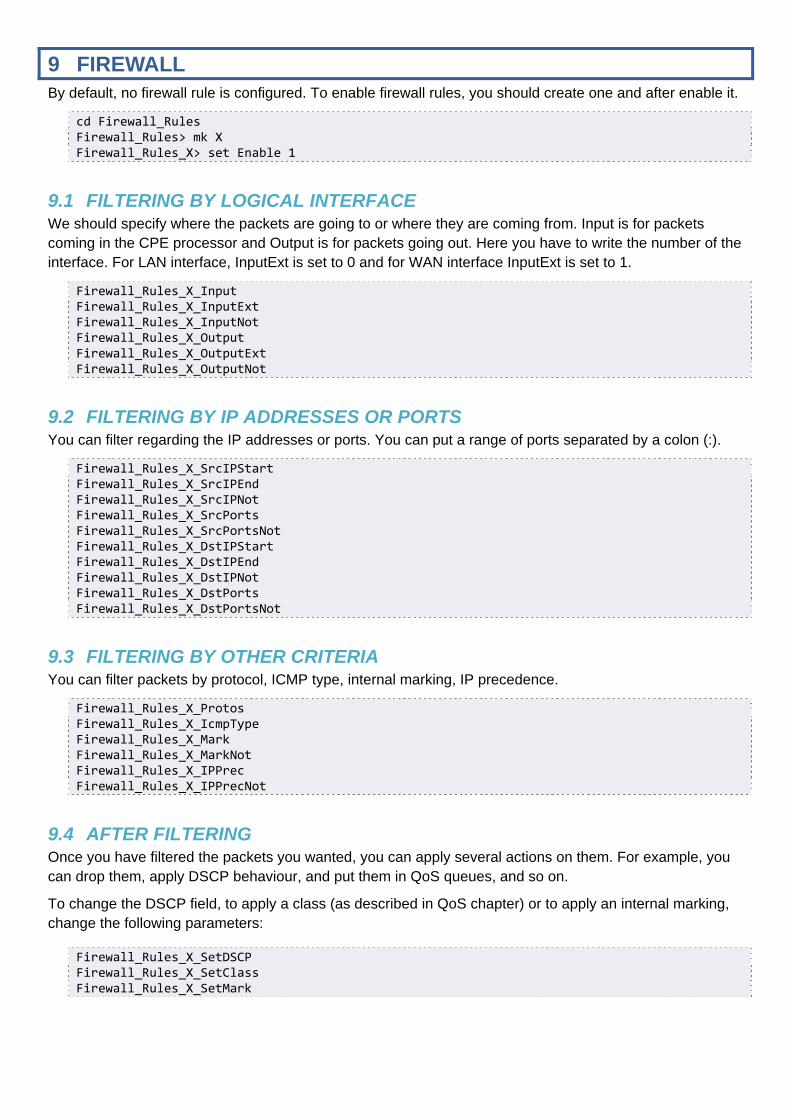
9 FIREWALL By default, no firewall rule is configured. To enable firewall rules, you should create one and after enable it.
cd Firewall_Rules Firewall_Rules> mk X Firewall_Rules_X> set Enable 1
9.1 FILTERING BY LOGICAL INTERFACE We should specify where the packets are going to or where they are coming from. Input is for packets coming in the CPE processor and Output is for packets going out. Here you have to write the number of the interface. For LAN interface, InputExt is set to 0 and for WAN interface InputExt is set to 1.
Firewall_Rules_X_Input Firewall_Rules_X_InputExt Firewall_Rules_X_InputNot Firewall_Rules_X_Output Firewall_Rules_X_OutputExt Firewall_Rules_X_OutputNot
9.2 FILTERING BY IP ADDRESSES OR PORTS You can filter regarding the IP addresses or ports. You can put a range of ports separated by a colon (:).
Firewall_Rules_X_SrcIPStart Firewall_Rules_X_SrcIPEnd Firewall_Rules_X_SrcIPNot Firewall_Rules_X_SrcPorts Firewall_Rules_X_SrcPortsNot Firewall_Rules_X_DstIPStart Firewall_Rules_X_DstIPEnd Firewall_Rules_X_DstIPNot Firewall_Rules_X_DstPorts Firewall_Rules_X_DstPortsNot
9.3 FILTERING BY OTHER CRITERIA You can filter packets by protocol, ICMP type, internal marking, IP precedence.
Firewall_Rules_X_Protos Firewall_Rules_X_IcmpType Firewall_Rules_X_Mark Firewall_Rules_X_MarkNot Firewall_Rules_X_IPPrec Firewall_Rules_X_IPPrecNot
9.4 AFTER FILTERING Once you have filtered the packets you wanted, you can apply several actions on them. For example, you can drop them, apply DSCP behaviour, and put them in QoS queues, and so on.
To change the DSCP field, to apply a class (as described in QoS chapter) or to apply an internal marking, change the following parameters:
Firewall_Rules_X_SetDSCP Firewall_Rules_X_SetClass Firewall_Rules_X_SetMark

10 QOS
Quality of Service allows efficient bandwidth allocation per queues, by prioritize:
- First: Voice traffic - Second: Business applications (Videoconferencing for example) traffic - Last: Best Effort traffic (Internet)
To activate QoS on the gateway, you should enable it:
QueueManagement_Enable=1
QoS queues can be configured depending on customer requirements, while respecting the maximum value of WAN architecture (for example, 8 queues available in case of VDSL or WAN Ethernet architecture):
QueueManagement_MaxQueues=8
Furthermore, to enable logs and debug when queues are created:
QueueManagement_Debug=1
10.1 LINUX CLASSES AND QUEUES
10.1.1 MAPPING CLASS VERSUS QUEUE
The mapping class algorithm depends on WAN interface and on hardware.
Linux Class Queue Priority
0 7 Best Effort
1 6
2 5
3 4
4 3
5 2
6 1
7 0 Strict Priority
The other queues should be configured depending on the customer traffic, in order to prioritize for example:
- Video conference traffic - Business application - Mail traffic - Gaming traffic - Management traffic

10.1.2 DEFAULT QUEUING PER DSCP VALUE
This array shows the link between DSCP field and ToS field.
Diffserv field ToS Byte
DSCP DiffServ Byte Precedence T2;T1;T0
af11 001010 00101000 0x28 40 001 010 Maximize Throughput (MT)
af12 001100 00110000 0x30 48 001 100 Minimize Delay (MD)
af13 001110 00111000 0x38 56 001 110 MT + MD
af21 010010 01001000 0x48 72 010 010 Maximize Throughput
af22 010100 01010000 0x50 80 010 100 Minimize Delay
af23 010110 01011000 0x58 88 010 110 MT + MD
af31 011010 01101000 0x68 104 011 010 Maximize Throughput
af32 011100 01110000 0x70 112 011 100 Minimize Delay
af33 011110 01111000 0x78 120 011 110 MT + MD
af41 100010 10001000 0x88 136 100 010 Maximize Throughput
af42 100100 10010000 0x90 144 100 100 Minimize Delay
af43 100110 10011000 0x98 152 100 110 MT + MD
cs1 001000 00100000 0x20 32 001 000 Normal Service
cs2 010000 01000000 0x40 64 010 000 Normal Service
cs3 011000 01100000 0x60 96 011 000 Normal Service
cs4 100000 10000000 0x80 128 100 000 Normal Service
cs5 101000 10100000 0xA0 160 101 000 Normal Service
cs6 110000 11000000 0xC0 192 110 000 Normal Service
cs7 111000 11100000 0xE0 224 111 000 Normal Service
default 000000 00000000 0x00 0 000 000 Normal Service
EF 101110 10111000 0xB8 184 101 110 MT + MD
10.2 CONFIGURE QOS Two QoS algorithms are implemented in the software:
- Priority Queuing (PQ) - Weighted Fair Queuing (PQ)
To activate one specified queue:
QueueManagement_Queue_1_Enable=1
One queue must be unique per interface, because one interface is defined by two parameters:
- InterfaceType - InterfaceIndex

QueueManagement_Queue_1_QueueId=<queue_id_value>
To specify a scheduler algorithm to use:
QueueManagement_Queue_1_SchedulerAlgorithm=<PQ_or_WFQ>
To set a value for the queue weight:
QueueManagement_Queue_1_QueueWeight=<weight_value>
Example of 2 WFQ queues in case of Ethernet WAN architecture:
QueueManagement_Queue_1_Enable=1 QueueManagement_Queue_1_Description='Prio1' QueueManagement_Queue_1_QueueId=0 QueueManagement_Queue_1_InterfaceType='LANEthernetInterface' QueueManagement_Queue_1_InterfaceIndex=2 QueueManagement_Queue_1_SchedulerAlgorithm='WFQ' QueueManagement_Queue_1_QueueWeight=100 QueueManagement_Queue_2_Enable=1 QueueManagement_Queue_2_Description='Prio2' QueueManagement_Queue_2_QueueId=1 QueueManagement_Queue_2_InterfaceType='LANEthernetInterface' QueueManagement_Queue_2_InterfaceIndex=2 QueueManagement_Queue_2_SchedulerAlgorithm='WFQ' QueueManagement_Queue_2_QueueWeight=50
Note: If QueueWeight=100, PQ behavior is applied even if WFQ is set for SchedulerAlgorithm parameter.
10.3 VOIP TRAFFIC The Pace Box allows marking on the Voice packets and on RTP packets, which come from FXS ports and Voice Processor.
For example: With a class equals to Expedited Forwarding (EF):
IP Precedence 5 = 101 <=> DiffservByte = 101110(00) = 184
Step 1: Mark the traffic
VoiceProfile_1_SIP_DSCPMark=46 VoiceProfile_1_RTP_DSCPMark=46
Step 2: Forward the traffic
Firewall_Rules_X_Enable=1 Firewall_Rules_X_User=0 Firewall_Rules_X_Description='IP precedence 5 to High Priority Queue' Firewall_Rules_X_IPPrec=5 Firewall_Rules_X_SetClass=7 Firewall_Rules_X_Chain='Postrouting'

10.4 OTHER TRAFFIC For example: With a class equals for RTCP with DSCP = 24
DSCP= 24 DiffservByte = 011000(00) = 96 IP precedence = 3
First rule to mark the VoIP traffic
Firewall_Rules_5_Enable=1 Firewall_Rules_5_Description="mark RTCP traffic with DSCP 24"
Enter the UDP ports used by RTC. p1:p2 is a range
Firewall_Rules_5_Protos='udp' Firewall_Rules_5_DstPorts=p1:p2
Set the DSCP value:
Firewall_Rules_5_SetDSCP=96
Second rule to forward the traffic in a medium priority queue
Firewall_Rules_6_Enable=1 Firewall_Rules_6_Description="Forward the traffic to the a medium priority queue"
Sort the traffic by IP precedence:
Firewall_Rules_6_IPPrec=3
Forward the traffic in a medium priority queue:
Firewall_Rules_6_SetClass=4

11 PROVISIONING & REMOTE MANAGEMENT
There are two ways of enabling the provisioning and the firmware upgrade. You can either do it with TR-069 or with FTP/HTTP. Both are described here.
11.1 TR-069 To initiate the first connectivity with a TR-069 ACS, these parameters must be set:
• URL of the ACS • Login/Password of the ACS HTTP server • Login/Password of the CPE HTTP server used for Connection Requests
Then you can configure the TR-069 server as following:
Services_TR069_Enable=1 Services_TR069_ACSUrl='your‐acs‐url' Services_TR069_ACSLogin='your‐acs‐login' Services_TR069_ACSPassword='your‐acs‐password' Services_TR069_SrvLogin='the‐cpe‐login' Services_TR069_SrvPassword='the‐cpe‐password'
These are the basic parameters in order to make TR-069 work. The first parameter is to enable the checking and the second parameter is for entering the certificate to compare.
Services_TR069_VerifyCert=1 Services_TR069_ACSCertPem='‐‐‐‐‐BEGIN CERTIFICATE‐‐‐‐‐ MIIDjzCCAvigAwIBAgIEPII/2zANBgkqhkiG9w0BAQUFADA2MQswCQYDVQQGEwJF UzENMAsGA1UEChMERk5NVDEYMBYGA1UECxMPRk5NVCBDbGFzZSAyIENBMB4XDTA1 MDUyMzEzMzY1MloXDTA5MDUyMzEzMzY1MlowczELMAkGA1UEBhMCRVMxDTALBgNV MA0GCSqGSIb3DQEBBQUAA4GBAHlFBM4DuIaCSVAIYuZz7VtUe+2oTNi6TFZCzHCF bGljb3MxEjAQBgNVBAsTCTUwMDA3MDAxNTEUMBIGA1UEAxMLVzEuUkVORkUuRVMw gZ8wDQYJKoZIhvcNAQEBBQADgY0AMIGJAoGBAOEK/TzlOqjk0vlZW6VHpxScs2kG Nm3zSEIBPnNPFkgaDXANlQseBmaSf9s2XFe7YWkXkGFBfOtscdb+RmL7SXWxk2fE osGxTKR7g4mdYVR1b1H6KB7nOfhduSL6vWHA5heVVBQVpnNGE+Bh7NesAjIS6X2o y3vB5AzQ9gyUBcBjAgMBAAGjggFrMIIBZzBwBgNVHREEaTBnpFgwVjEYMBYGCSsG AQQBrGYBDxMJRzg0MTQ0MTYxMR4wHAYJKwYBBAGsZgEOEw9SRU5GRSBPUEVSQURP UkExGjAYBgkrBgEEAaxmAQgTC1cxLlJFTkZFLkVTggtXMS5SRU5GRS5FUzAJBgNV HRMEAjAAMCsGA1UdEAQkMCKADzIwMDUwNTIzMTMzNjUyWoEPMjAwOTA1MjMxMzM2 NTJaMAsGA1UdDwQEAwIFoDARBglghkgBhvhCAQEEBAMCBkAwHQYDVR0OBBYEFAFs mb270FNdSCdOQKg7giVVDA9UMB8GA1UdIwQYMBaAFECadkSXdAfErBTLHo1POkV8 MNdhMFsGA1UdHwRUMFIwUKBOoEykSjBIMQswCQYDVQQGEwJFUzENMAsGA1UEChME Rk5NVDEYMBYGA1UECxMPRk5NVCBDbGFzZSAyIENBMRAwDgYDVQQDEwdDUkwyMDAx MA0GCSqGSIb3DQEBBQUAA4GBAHlFBM4DuIaCSVAIYuZz7VtUe+2oTNi6TFZCzHCF PNAemuBF1ZiUZ7ceNg6BH6hveakeZ4uClBRULMxDQYlu3h8NzgQbv3G6+xf0Xw+F HWmuA5EX15CnhkzGhFyUeeFfj1LjrfTacxaE4gWhDdOEznvszFH7pRrQBJWEZjq+ QiHn ‐‐‐‐‐END CERTIFICATE‐‐‐‐‐'
When the CPE is upgraded via TR-069, the CPE must reboot. When there is no longer significant traffic, the CPE can be set in order to reboot at this moment. It avoids the end-customers to have an interruption of service (voice or TV for example). This functionality can be enabled as followed:
Services_TR069_RebootNoTraffic=1
If this value is set to 1, reboot will only take place when no traffic is detected during an amount of time in the WAN interface. If set to 0, the reboot needs to be manual.

11.2 FTP OR HTTP PROVISIONING This is a diagram of ftp or http provisioning steps, when the CPE starts:

11.2.1 CONFIGURATION PARAMETERS
In order to activate the FTP Provisioning, these CLI parameters should be configured:
Services_FtpProvisioning (obj) Services_FtpProvisioning_Enable (bool) -- enable or disable the service Services_FtpProvisioning_FtpInformationServer (string) – IP address or domain name of the
Information file server Services_FtpProvisioning_InformationLogin (string) -- login for the Information file server Services_FtpProvisioning_InformationPassword (string) -- password for the Information file
server Services_FtpProvisioning_InformationFilename (string) -- filename to download from the
Information file server Services_FtpProvisioning_InformationServerProtocol [ftp|http] -- the protocol needed to
connect on the information server
11.2.2 INFORMATION FILES
All information of FTP provisioning can be listed in a file (also called FWINFO) formatted like this:
FIRMWARE_FILENAME=path/to/firmware.bin FIRMWARE_SERVER=example.com FIRMWARE_SERVER_PROTOCOL=ftp FIRMWARE_USER=foo FIRMWARE_PASSWORD=bar CONFIGURATION_FILENAME=path/to/cli‐script.conf CONFIGURATION_SERVER=example.com CONFIGURATION_SERVER_PROTOCOL=ftp CONFIGURATION_USER=foo CONFIGURATION_PASSWORD=bar
11.2.3 ABOUT VARIABLES CONTENT
In the CLI values and FWINFO files, the following magic patterns can be used to be automatically replaced with the correct value:
%MAC -- the MAC address of the CPE
%SN -- the serial number
%KEEPSERVER -- the name of the FWINFO server
%KEEPUSER -- the login of the FWINFO server
%KEEPPASSWORD -- the password of the FWINFO server
%KEEPSERVERPROTOCOL -- the password of the FWINFO server
Therefore, the configuration will be easier, by removing all redundant information. Example (FWINFO file):
FIRMWARE_NAME=path/to/firmware.bin FIRMWARE_SERVER=%KEEPSERVER FIRMWARE_SERVER_PROTOCOL=%KEEPSERVERPROTOCOL FIRMWARE_USER=%KEEPUSER FIRMWARE_PASSWORD=%KEEPPASSWORD CONFIGURATION_FILENAME=path/to/the‐specific‐cli‐script‐for‐%MAC.conf CONFIGURATION_SERVER_PROTOCOL=%KEEPSERVERPROTOCOL CONFIGURATION_SERVER=%KEEPSERVER CONFIGURATION_USER=%KEEPUSER CONFIGURATION_PASSWORD=%KEEPPASSWORD

12 IGMP MANAGEMENT
IGMP snooping and IGMP proxy are two different ways of managing the IGMP messages.
The IGMP snooping (RFC 4541) can be used only in layer 2 network design. In our case, it is when we have a bridge configuration between a WAN interface and an Ethernet interface.
The IGMP proxy can be used only in layer 3 network design. That means the network design must be full routed between the different interfaces.
12.1 IGMP SNOOPING In the Pace Box, there are two types of IGMP snooping, one based on hardware layer and another one based on software layer (bridge Linux, with ebtables library).
To clarify both IGMP snooping:
The software snooping is the snooping between the Linux interfaces (eth0.2 and wan2, in a configuration where the wan2 is bridged on the eth0.2)
The hardware snooping is the snooping managed directly by the Ethernet switch. Layer2Bridging_Enable=1 Layer2Bridging_InputPolicy=1 Layer2Bridging_OutputPolicy=1 Layer2Bridging_ForwardPolicy=1 Layer2Bridging_IGMPSnooping_Enable=1 Layer2Bridging_IGMPSnooping_Output_List=1 Layer2Bridging_IGMPSnooping_Exclude_List=1 Layer2Bridging_IGMPSnoopingTable_Interface_Count=1
To activate IGMP Snooping on LAN interface, you should configure this line:
LANEthernetInterface_1_SwitchIGMPEnable=1
Below this option, you can configure all multicast group you would like:
LANEthernetInterface_1_IGMPMulticastTable_MulticastGroup_1_Group=<IGMP_group_address> LANEthernetInterface_1_IGMPMulticastTable_MulticastGroup_1_ForwardPort_1_Port=<IGMP_port> LANEthernetInterface_1_IGMPMulticastTable_MulticastGroup_1_ForwardPort_1_Age=0 LANEthernetInterface_1_IGMPMulticastTable_MulticastGroup_1_ForwardPort_1_SourceFilteringMode=1 LANEthernetInterface_1_IGMPMulticastTable_MulticastGroup_1_ForwardPort_Count=1
12.2 IGMP PROXY In order to make IGMP proxy work, few parameters have to be filled. Two types of interfaces exist:
- the upstream interface which is the interface from where you send the IGMP reports - the downstream interface from where you receive the multicast streams
It is enabled by default, but the IGMP proxy parameters must be enabled with UpstreamInterface at an empty value in order to let the IGMP snooping work.
Services_IgmpProxy_Enable=1 Services_IgmpProxy_LogLevel=1 Services_IgmpProxy_QuickLeave=1 Services_IgmpProxy_HostTracking=0 Services_IgmpProxy_UpstreamInterface=<WANConnectionDevice_Index> Services_IgmpProxy_DownstreamInterfaces=<LANEthernetInterface_Index>

13 ANNEX: CONFIGURATION EXAMPLES
A.1 BRIDGING AN ETHERNET PORT ON A WAN INTERFACE In order to isolate Ethernet ports, we should create internal VLANs. Here, we will use the Ethernet port 4 as the bridge port. We create two VLANs: VLAN #1 for the classic LAN #1 (used for ports 1, 2 and 3) and the VLAN #2 for the LAN #2 (used for port 4) which is the bridge between the Ethernet port and the WAN interface. To assign VLANs to Ethernet ports:
LANEthernetInterface_1_SwitchVLANEnable=1 LANEthernetInterface_1_VLANInterface_1_VID=1 LANEthernetInterface_1_VLANInterface_1_Enable=1 LANEthernetInterface_1_VLANInterface_2_VID=2 LANEthernetInterface_1_VLANInterface_2_Enable=1 LANEthernetInterface_1_Port_1_VLANInterface=1 LANEthernetInterface_1_Port_2_VLANInterface=1 LANEthernetInterface_1_Port_3_VLANInterface=1 LANEthernetInterface_1_Port_4_VLANInterface=2
To link the VLAN #1 to the LAN #1:
LANDevice_1_LANEthernetInterface_1_Enable=0 LANDevice_1_LANEthernetInterface_1_VLANInterface_1_Enable=1
To link the VLAN #2 to the LAN #2 and creating the LAN #2:
LANDevice_2_Enable=1 LANDevice_2_IPInterface_1_IPAddress=192.168.2.1 LANDevice_2_IPInterface_1_SubnetMask=255.255.255.0 LANDevice_2_HostConfig_DHCPServerEnable=0 LANDevice_2_LANEthernetInterface_1_Enable=0 LANDevice_2_LANEthernetInterface_1_VLANInterface_2_Enable=1
To create the bridge between the Ethernet port and the WAN interface, we must activate the ‘passthrough’ mode on the LAN #2. Here we are bridging with the WAN #2.
LANDevice_2_HostConfig_UseAllocatedWAN='Passthrough' LANDevice_2_HostConfig_AssociatedConnection=2
The WAN #2 must have the following parameters set to be bridged.
WANConnectionDevice_2_Enable=1 WANConnectionDevice_2_WANPPPConnection_Enable=0 WANConnectionDevice_2_WANIPConnection_Enable=0

A.2 TRUNKING CONFIGURATION Here is an example of configuration for the VLAN trunking. Below is the architecture scheme.
First, we configure the WAN interfaces like this:
- the WAN #1 is for the Internet service - the WAN #2 is for the VoIP service
WANConnectionDevice_1_Enable=1 WANConnectionDevice_1_PhysicalInterface_Type='LANEthernetInterface' WANConnectionDevice_1_PhysicalInterface_VlanNumber=10 WANConnectionDevice_1_WANPPPConnection_Enable=1 WANConnectionDevice_1_WANPPPConnection_Username='[email protected]' WANConnectionDevice_1_WANPPPConnection_Password='pppPassword' WANConnectionDevice_1_DNSEnable=1 WANConnectionDevice_1_NATEnable=1 WANConnectionDevice_2_Enable=1 WANConnectionDevice_2_PhysicalInterface_Type='LANEthernetInterface' WANConnectionDevice_2_PhysicalInterface_VlanNumber=12 WANConnectionDevice_2_WANIPConnection_Enable=1 WANConnectionDevice_2_WANIPConnection_AddressingType='DHCP' WANConnectionDevice_2_DNSEnable=1 WANConnectionDevice_2_NATEnable=0
Then we configure the VLANs for the LAN and for the VLAN trunking, according to the previous scheme.
LANEthernetInterface_1_Port_1_VLANInterface=11 LANEthernetInterface_1_Port_2_VLANInterface=1 LANEthernetInterface_1_Port_3_VLANInterface=1 LANEthernetInterface_1_Port_4_VLANInterface=2 LANEthernetInterface_1_Port_4_VLANTrunk=10,11,12 LANEthernetInterface_1_VLANInterface_1_VID=1 LANEthernetInterface_1_VLANInterface_1_Enable=1
Ethernet
FXS
Voice
Gateway
1
2
3
4
1
2
WAN1: PPPoE + NAT
WAN2: DHCP
bridge
VLA
N 1
VLAN trunk
LAN
VLAN 519 (#10) VLAN 3010 (#11)VLAN 2519 (#12)
TV

LANEthernetInterface_1_VLANInterface_2_VID=2 LANEthernetInterface_1_VLANInterface_2_Enable=1 LANEthernetInterface_1_VLANInterface_10_VID=519 LANEthernetInterface_1_VLANInterface_10_Enable=1 LANEthernetInterface_1_VLANInterface_11_VID=3010 LANEthernetInterface_1_VLANInterface_11_Enable=1 LANEthernetInterface_1_VLANInterface_12_VID=2519 LANEthernetInterface_1_VLANInterface_12_Enable=1 LANEthernetInterface_1_SwitchVLANEnable=1
To link VLAN #1 to LAN #1:
LANDevice_1_Enable=1 LANDevice_1_LANEthernetInterface_1_Enable=0 LANDevice_1_LANEthernetInterface_1_VLANInterface_1_Enable=1
To changing the WAN interface for the VoIP service:
Voice_Enable=1 Voice_WANInterface=2

14 ANNEX: TROUBLESHOOTING
Once your configuration done, depending on its complexity level, it is important to remind some configuration lines. Thus, some commands are described here and can be used to troubleshooting the CPE. All these commands are available when you access on the CPE by telnet using the credentials root/hemingway and then execute the command diag.
A.3 “LOGREAD -F” With “logread -f” command, all logs generated by the CPE may be displayed, included the name of the process and the realized action by the process.
Jan 1 02:07:22 pppd[881]: Timeout waiting for PADO packets Jan 1 02:07:22 pppd[881]: Unable to complete PPPoE Discovery
Here, for example, we see some logs from ‘pppd’ (process which manages the PPP connections). You can precise debug level in order to get more information for some processes:
A.3.1 MORE DEBUG ON PPP CONNECTIONS To improve debug level for PPP connections, you must enable a parameter in the CLI regarding to the WAN interface you would like to debug. For WAN1, you should set the following parameter:
WANConnectionDevice_1_WANPPPConnection_Debug=1
A.3.2 MORE DEBUG ON VOIP To obtain detailed debug logs, you must open a Telnet session using a root account and configure the following commands:
cd Voice set Debug 3 set Trace 1 fcommit
Note that debug levels 3 and 4 allow logs on application layer and on phone library layer. Moreover, with Trace activated, it’s possible to investigate on SIP incoming and outgoing packets body.
A.4 TCPDUMP This command allows a deep diagnosis inside L2 frames included TCP handshake, errors and so on. This trace can be captured in a “.pcap” format file and be opened with Wireshark. You can save this capture in a USB device connected to the gateway, using this command:
tcpdump –i <interface> ‐pn –s 0 –w /var/mnt/<filesystem>/<filename>.pcap
<interface> -- interface from which you want to capture logs
<filesystem> -- stands for the filesystem of the USB device
<filename> -- the file name to give

A.5 COMMAND “IFCONFIG” By typing this command, you can see all the network interfaces and their status. For example, you can see if your ATM interface has been well declared and if the IP addresses are well assigned for all interfaces.
atm4 Link encap:Ethernet HWaddr 00:0C:C3:73:04:1D UP BROADCAST RUNNING MULTICAST MTU:1500 Metric:1 RX packets:0 errors:0 dropped:0 overruns:0 frame:0 TX packets:0 errors:0 dropped:0 overruns:0 carrier:0 collisions:0 txqueuelen:100 RX bytes:0 (0.0 B) TX bytes:0 (0.0 B) eth0 Link encap:Ethernet HWaddr 00:0C:C3:73:04:1D UP BROADCAST RUNNING MULTICAST MTU:1500 Metric:1 RX packets:663 errors:0 dropped:0 overruns:0 frame:0 TX packets:16870 errors:0 dropped:0 overruns:0 carrier:0 collisions:0 txqueuelen:100 RX bytes:63082 (61.6 KiB) TX bytes:1136858 (1.0 MiB) lan1 Link encap:Ethernet HWaddr 00:0C:C3:73:04:1D inet addr:192.168.1.1 Bcast:192.168.1.255 Mask:255.255.255.0 UP BROADCAST RUNNING MULTICAST MTU:1500 Metric:1 RX packets:663 errors:0 dropped:0 overruns:0 frame:0 TX packets:1709 errors:0 dropped:0 overruns:0 carrier:0 collisions:0 txqueuelen:0 RX bytes:51148 (49.9 KiB) TX bytes:205999 (201.1 KiB) lo Link encap:Local Loopback inet addr:127.0.0.1 Mask:255.0.0.0 UP LOOPBACK RUNNING MTU:16436 Metric:1 RX packets:1638 errors:0 dropped:0 overruns:0 frame:0 TX packets:1638 errors:0 dropped:0 overruns:0 carrier:0 collisions:0 txqueuelen:0 RX bytes:98274 (95.9 KiB) TX bytes:98274 (95.9 KiB) wan1 Link encap:Ethernet HWaddr 00:0C:C3:73:04:1D UP BROADCAST RUNNING MTU:1500 Metric:1 RX packets:0 errors:0 dropped:0 overruns:0 frame:0 TX packets:758 errors:0 dropped:0 overruns:0 carrier:0 collisions:0 txqueuelen:0 RX bytes:0 (0.0 B) TX bytes:24256 (23.6 KiB)
A.6 COMMAND “ADSLINFO” By typing this command, you will see all information related to the ADSL synchronisation status:
DSP version : 5.3.3.11.1.1 line state : Full On modulation : G.992.5 A (ADSL2+) time connected : 00:00:32 up occupation (%) : 0 down occupation (%) : 100 up max rate (kbps) : 1623242 down max rate (kbps) : 22884 up actual rate (kbps) : 1021 down actual rate (kbps) : 22884 up interleaved rate (kbps) : 1021 down interleaved rate (kbps) : 22884

up fast channel rate (kbps) : 0 down fast channel rate (kbps) : 0 up interleaved delay (ms) : 5 down interleaved delay (ms) : 5 up noise margin (dB) : 2476.8 down noise margin (dB) : 6.0 up attenuation (dB) : 2476.8 down attenuation (dB) : 8.4 up output power (dBm) : 0.0 down output power (dBm) : 11.2 local FECs : 0 remote FECs : 0 local HECs : 0 remote HECs : 0 local CRCs : 1 remote CRCs : 0 ATUC provider : GSPN ATUR provider : AWRE