Embed Size (px)
Citation preview

Helicopter Maritime Environment Trainer: Software Product Specification
Edited by:
Leo Boutette Ken Ueno Jason Dielschneider
This manual represents the operation of the HelMET System as originally installed with hardware updates to the current date. For current system start-up procedures consult the Helicopter Maritime Environment Trainer (HelMET) Start-Up, Virtual Lesson Plan (VLP) Editor & Shutdown Manual Application Version 4.0. For current Operational Procedures consult the Helmet 4 4 IOS User's Guide _Rev_011
Defence R&D Canada
Technical Memorandum DRDC Toronto TM 2011-050 June 2011


Helicopter Maritime Environment Trainer: Software Product Specification
Edited by: Leo Boutette Ken Ueno Jason Dielschneider
Defence R&D Canada – Toronto Technical Memorandum DRDC Toronto TM 2011-050 June 2011
This manual represents the operation of the HelMET System as originally installed with hardware updates to the current date. For current system start-up procedures consult the Helicopter Maritime Environment Trainer (HelMET) Start-Up, Virtual Lesson Plan (VLP) Editor & Shutdown Manual Application Version 4.0. For current Operational Procedures consult the Helmet 4 4 IOS User's Guide _Rev_011.

Principal Author
Original signed by See Original Document. Edited by: Leo Boutette; Ken Ueno; Jason Dielschneider
See Original Document. Edited by: Leo Boutette; Ken Ueno; Jason Dielschneider Human Effectiveness Exploitation Centre
Approved by
Original signed by David Eaton
David Eaton Section Head, Human Effectiveness Exploitation Centre
Approved for release by
Original signed by Dr. Stergios Stergiopolous
Dr. Stergios Stergiopolous Acting Chair, Knowledge and Information Management Committee
Acting Chief Scientist
This document is a revision of DRDC Toronto Document: CR2002-030 Atlantis Document: AP905-03128 titled Helicopter Maritime Environment Trainer: Software Product Specification with updates to Version 4.4 of the HelMET software.
© Her Majesty the Queen in Right of Canada, as represented by the Minister of National Defence, 2011
© Sa Majesté la Reine (en droit du Canada), telle que représentée par le ministre de la Défense nationale, 2011

DRDC Toronto TM 2011-050 i
Abstract ……..
The Helicopter Maritime Environment Trainer (HelMET) was developed by Defence R&D Canada – Toronto (DRDC Toronto) for training helicopter pilots to land on the flight deck of a Canadian Patrol Frigate (CPF) in a virtual environment. The HelMET was installed at 12 Wing, Canadian Forces Base (CFB) Shearwater, Nova Scotia, Canada [reference: Summary per document cited in next paragraph]. DRDC Toronto Document: CR2002-030 Atlantis Document: AP905-03128 titled Helicopter Maritime Environment Trainer: Software Product Specification documented Version 1.1 of the HelMET Software. As third party support for the HelMET system did not come to fruition, DRDC Toronto has been supporting the HelMET system at 12th Wing Shearwater with hardware and software updates. The current version of HelMET is Version 4.4. Many of the updates implemented were made to allow the simulator to be used as a procedures trainer. This document is a revision of CR2002-030 updated to reflect the large number of changes that have been implemented by DRDC Toronto since version 1.1. The purpose of this document is to update the description so that the system can be maintained and operated by Director Aerospace Development Program Management, Radar and Communications Systems or its representatives.
Résumé ….....
Le Simulateur d’entraînement virtuel pour hélicoptère maritime (HelMET) a été développé par Recherche et développement pour la défense Canada – Toronto (RDDC Toronto) afin d’entraîner les pilotes d’hélicoptère à l’atterrissage sur le pont d’envol d’une frégate canadienne de patrouille dans un environnement virtuel. Le système HelMET a été installé à la 12e Escadre, Base des Forces canadiennes Shearwater, Nouvelle-Écosse, Canada [référence : sommaire par document cité dans le paragraphe suivant]. Document RDDC Toronto : CR2002-030, document Atlantis : AP905-03128 intitulé Simulateur d’entraînement virtuel pour hélicoptère maritime : Spécification de produit logiciel, documentation de la version 1.1 du logiciel HelMET. Étant donné que la prise en charge du système HelMET par un tiers ne s’est pas réalisée, c’est RDDC Toronto qui en assure, par conséquent, le soutien à la 12e Escadre Shearwater au moyen de mises à niveau de matériel et de mises à jour de logiciel. La dernière version du logiciel HelMET est la version 4.4. De nombreuses fonctionnalités qui ont été implémentées visaient à permettre au simulateur d’être utilisé comme système d’entraînement aux procédures.

ii DRDC Toronto TM 2011-050
Le présent document est une révision du document CR2002-030 dont la mise à jour vise à refléter le grand nombre de modifications apportées au logiciel par RDDC Toronto depuis la version 1.1. L’objectif de ce document est de mettre à jour les descriptions de façon à ce que le système puisse être maintenu et utilisé par le Directeur – Gestion du programme de développement aérospatial (système de radar et de communication) ou ses représentants.

DRDC Toronto TM 2011-050 iii
Executive summary
Helicopter Maritime Environment Trainer: Software Product Specification:
Leo Boutette; DRDC Toronto TM 2011-050; Defence R&D Canada – Toronto; June 2011.
The Helicopter Maritime Environment Trainer (HelMET) was developed by Defence R&D Canada – Toronto (DRDC Toronto) for training helicopter pilots to land on the flight deck of a Canadian Patrol Frigate (CPF) in a virtual environment. The HelMET was installed at 12 Wing, Canadian Forces Base (CFB) Shearwater, Nova Scotia, Canada [reference Summary per document cited in next paragraph]. DRDC Toronto Document: CR2002-030 Atlantis Document: AP905-03128 titled Helicopter Maritime Environment Trainer: Software Product Specification documented Version 1.1 of the HelMET Software. As third party support for the HelMET system did not come to fruition, DRDC Toronto has been supporting the HelMET system at 12th Wing Shearwater with hardware and software updates. The current version of HelMET is Version 4.4. Many of the updates implemented were made to allow the simulator to be used as a procedures trainer. This document is a revision of CR2002-030 updated to reflect the large number of changes that have been implemented by DRDC Toronto since version 1.1. The purpose of this document is to update the description so that the system can be maintained and operated by Director Aerospace Development Program Management, Radar and Communications Systems or its representatives.

iv DRDC Toronto TM 2011-050
Sommaire .....
Helicopter Maritime Environment Trainer: Software Product Specification:
Leo Boutette; DRDC Toronto TM 2011-050; R & D pour la défense Canada – Toronto; Juin 2011.
Le Simulateur d’entraînement virtuel pour hélicoptère maritime (HelMET) a été développé par Recherche et développement pour la défense Canada – Toronto (RDDC Toronto) afin d’entraîner les pilotes d’hélicoptère à l’atterrissage sur le pont d’envol d’une frégate canadienne de patrouille dans un environnement virtuel. Le système HelMET a été installé à la 12e Escadre, Base des Forces canadiennes Shearwater, Nouvelle-Écosse, Canada [référence : sommaire par document cité dans le paragraphe suivant]. Document RDDC Toronto : CR2002-030, document Atlantis : AP905-03128 intitulé Simulateur d’entraînement virtuel pour hélicoptère maritime : Spécification de produit logiciel, documentation de la version 1.1 du logiciel HelMET. Étant donné que la prise en charge du système HelMET par un tiers ne s’est pas réalisée, c’est RDDC Toronto qui en assure, par conséquent, le soutien à la 12e Escadre Shearwater au moyen de mises à niveau de matériel et de mises à jour de logiciel. La dernière version du logiciel HelMET est la version 4.4. De nombreuses fonctionnalités qui ont été implémentées visaient à permettre au simulateur d’être utilisé comme système d’entraînement aux procédures.
Le présent document est une révision du document CR2002-030 dont la mise à jour vise à refléter le grand nombre de modifications apportées au logiciel par RDDC Toronto depuis la version 1.1. L’objectif de ce document est de mettre à jour les descriptions de façon à ce que le système puisse être maintenu et utilisé par le Directeur – Gestion du programme de développement aérospatial (système de radar et de communication) ou ses représentants.

DRDC Toronto TM 2011-050 v
Table of contents
Abstract …….. ................................................................................................................................. i Résumé …..... ................................................................................................................................... i Executive summary ....................................................................................................................... iii Sommaire ..... .................................................................................................................................. iv
Table of contents ............................................................................................................................ v
List of figures .............................................................................................................................. viii List of tables .................................................................................................................................. ix
1 Scope. ....................................................................................................................................... 1 1.1 Identification.................................................................................................................. 1 1.2 System Description ........................................................................................................ 1
1.2.1 Simulator General Description ........................................................................ 1 1.3 System Overview ........................................................................................................... 4
1.3.1 Background ..................................................................................................... 4 1.3.2 Simulator System Description ......................................................................... 4
1.4 Document Overview ...................................................................................................... 8
2 Referenced Documents ............................................................................................................. 9
3 Requirements .......................................................................................................................... 11 3.1 Inventory of Material Released ................................................................................... 11
3.1.1 Support Software and Tools CSCI ................................................................ 11 3.1.1.1 Purchased COTS......................................................................... 11 3.1.1.2 Freeware OTS CSC .................................................................... 13 3.1.1.3 Customized OTS......................................................................... 14
3.1.2 HelMET Operational Software CSCI ........................................................... 17 3.1.2.1 Software Development Tools ..................................................... 17
4 Software Support Information ................................................................................................ 19 4.1 Related Documents ...................................................................................................... 19 4.2 Installation Instructions ............................................................................................... 19
4.2.1 Commercial Off-the-Shelf CSCI Installation Instructions ............................ 19 4.2.1.1 MS-DOS Operating System ....................................................... 19 4.2.1.2 Red Hat Linux Operating System ............................................... 19 4.2.1.3 RedHawk Linux Operating System ............................................ 20 4.2.1.4 DMSO HLA Run-time Infrastructure (RTI) ............................... 20 4.2.1.5 OpenGL Performer for Linux 3.1.1 ............................................ 20 4.2.1.6 CerealBox Driver ........................................................................ 20 4.2.1.7 Open Audio Library .................................................................... 21 4.2.1.8 Parallel Virtual Machine ............................................................. 21 4.2.1.9 Servos and Simulation Motion Platform Software ..................... 21

vi DRDC Toronto TM 2011-050
4.2.1.10 FREDYN .................................................................................... 22 4.2.1.11 Fast Light Tool Kit ..................................................................... 23 4.2.1.12 Fast Light User Interface Designer ............................................. 23 4.2.1.13 MATRIXx .................................................................................. 23 4.2.1.14 MultiGen Creator ........................................................................ 23
4.2.2 HelMET Operational Software CSCI Installation Instructions ..................... 24 4.3 Compilation/Build Procedures .................................................................................... 24
4.3.1 Compilation/Build Environment ................................................................... 24 4.3.1.1 Compilation/Build Environment On LINUX ............................. 24
4.3.2 Compilation/Build Process............................................................................ 25 4.3.2.1 Illustration of Build Process ....................................................... 26 4.3.2.2 Compilation/Build Process On LINUX ...................................... 28
4.4 Modification Procedures ............................................................................................. 31 4.4.1 Modification Environment ............................................................................ 31
4.4.1.1 Modification Environment On LINUX ...................................... 31 4.4.2 Modification Process ..................................................................................... 31
4.4.2.1 Modification Process on Linux ................................................... 31 4.5 Creating Installation CD Procedures ........................................................................... 35
4.5.1 Creating Installation CD for LINUX ............................................................ 35 4.6 Computer Hardware Resource Utilization .................................................................. 36 4.7 Possible Problems and Known Errors ......................................................................... 36
5 Notes . 37 5.1 Abbreviations and Acronyms ...................................................................................... 37
Annex A .. Simulator Software Directory Structure ...................................................................... 43 A.1 Simulator Software Directory Structure ...................................................................... 43
Annex B ... SMART Makefile Structure ........................................................................................ 48 B.1 SMART Makefile Structure ........................................................................................ 48 B.2 Definitions of mods, bins, libs and ii_files .................................................................. 49 B.3 Dependency Definition ................................................................................................ 49 B.4 Tracking Includes ........................................................................................................ 50 B.5 Example Makefiles ...................................................................................................... 51 B.6 List of SMART Make Files ......................................................................................... 53
B.6.1 SMART_defs.mk .......................................................................................... 53 B.6.2 SMART_defsLinux.mk ................................................................................. 56 B.6.3 SMART_deps.mk ......................................................................................... 56 B.6.4 SMART_libs.mk ........................................................................................... 59 B.6.5 SMART_rules.mk ......................................................................................... 62 B.6.6 SMART_sources.mk ..................................................................................... 63 B.6.7 SMART_makedirs.mk .................................................................................. 64 B.6.8 SMART_maketargets.mk.............................................................................. 65

DRDC Toronto TM 2011-050 vii
B.6.9 SMART_makebin.mk ................................................................................... 66 B.6.10 SMART_makebindefs.mk ............................................................................ 67 B.6.11 SMART_makelib.mk .................................................................................... 68 B.6.12 SMART_makelibdefs.mk ............................................................................. 69 B.6.13 SMART_makestaticlib.mk............................................................................ 70 B.6.14 SMART_makedynamiclib.mk ...................................................................... 71 B.6.15 SMART_makemod.mk ................................................................................. 72 B.6.16 SMART_makemoddefs.mk .......................................................................... 73
Annex C ... MatrixX Notes – Sea King Simulator.......................................................................... 74 C.1 MatrixX Notes – Sea King Simulator.......................................................................... 74 C.2 MatrixX Getting Started .............................................................................................. 74 C.3 Change in a Variable ................................................................................................... 75 C.4 Systembuild ................................................................................................................. 75 C.5 Save a Change ............................................................................................................. 76 C.6 AutoCode ..................................................................................................................... 76 C.7 Transfer AutoCode to the Sea King Development Directory ...................................... 76 C.8 Structure of the MatrixX Dynamics Code Model........................................................ 77 C.9 Troubleshooting Process ............................................................................................. 77
Annex D .. Modifications of Simulator Visual Models ................................................................. 79 D.1 Introduction ................................................................................................................. 79 D.2 Simulator Database Design and Concepts ................................................................... 80 D.3 Modification ................................................................................................................ 85 D.4 Summary...................................................................................................................... 90
Distribution list ............................................................................................................................. 92
viii DRDC Toronto TM 2011-050
List of figures
Figure 1 .... Simulator Floor Plan ...................................................................................................... 3
Figure 2 .... Simulator Block Diagram .............................................................................................. 7
DRDC Toronto TM 2011-050 ix
List of tables
Table 1 ..... MS-DOS Operating System Inventory of Material Released .................................... 11
Table 2 ..... OpenGL Performer for Linux V3.1.1 .......................................................................... 12
Table 3 ..... RedHawk Linux Operating System ............................................................................. 12
Table 4 .... CerealBox Driver Inventory of Material Released ...................................................... 13
Table 5 Linux Operating System Inventory of Material Released ................................................ 13
Table 6 ..... DMSO HLA Run-time Infrastructure (RTI) ............................................................. 14
Table 7 ..... PVM Inventory of Material Released ......................................................................... 14
Table 8 ..... Motion Platform Software inventory of Material Released ....................................... 15
Table 9 .... FREDYN Inventory of Material Released .................................................................. 15
Table 10 .. FLTK Inventory of Material Released ........................................................................ 16
Table 11 ... FLUID Inventory of Material Released ....................................................................... 16
Table 12 ... OpenAL Inventory of Material Released .................................................................... 16
Table 13 ... MATRIXx Inventory of Material Released ................................................................. 17
Table 14 ... MultiGen Creator Inventory of Material Released ...................................................... 18
Table 15 Compilation/Build Software Environments on LINUX ................................................. 25

x DRDC Toronto TM 2011-050
This page intentionally left blank.

DRDC Toronto TM 2011-050 1
1 Scope
1.1 Identification This Software Product Specification (SPS), DRDC Toronto’s Document Number CR2002-030, identifies and records the inventory of software contents and installation instructions required to build the HelMET Operational Software Computer Software Configuration Item (CSCI). This SPS also provides information needed for future software maintenance and updates of the HelMET.
1.2 System Description
1.2.1 Simulator General Description The HelMET CSCI is a training software that runs on the HelMET developed by the Defence R&D Canada - Toronto (DRDC Toronto) for training helicopter pilots to land on the flight deck of a Canadian Patrol Frigate (CPF) in a virtual environment. The Sea King HelMET, herein referred to as the simulator, Helicopter Deck Landing Simulator (HDLS), Virtual Reconfigurable Simulator (VR-Sim), or Reconfigurable Helicopter Simulator (RHS), is designed to provide comprehensive initial training and refresher courses in a virtual environment for pilots of Sea King helicopters in landing on a flight deck of a CPF. Use of the simulator provides for effective training and evaluation while minimizing the high cost of operating ship and aircraft for training missions and eliminating the inherent danger of personnel injury and/or damage of aircraft and ship. The HelMET was installed at 12 Wing, Canadian Forces Base (CFB) Shearwater, Nova Scotia, Canada. The simulator consists of the following major areas as illustrated in Figure 1.
•Administration Station •Low Frequency Station •Instructor Operator Station (IOS) •Trainee Pilot Station •Second Pilot Station •Landing Signals Officer (LSO) Station •Equipment Rack Station2 •Motion Platform Power Station •Equipment Rack Station1 •Medium Frequency Station •Audio Communication Subsystem Station
The Administration Station provides the computing facilities for simulations and controls.

2 DRDC Toronto TM 2011-050
The Low Frequency Station houses two low frequency loud speakers. The Instructor Operator Station provides the instructor operator with the necessary controls and displays to effectively control, monitor, communicate and evaluate a helicopter deck landing training exercise. The Trainee Pilot Station provides a crew station for the pilot to be trained in a virtual environment. The station is equipped with a head-mounted display (HMD) with headset, pilot seat, cyclic pitch stick, collective pitch lever and tail rotor pedals housed on an electric motion base. The Second Pilot Station provides a crew station for the pilot to assist in training a trainee pilot in a virtual environment. The station is equipped with a head-mounted display (HMD) with headset, pilot seat, and controls for the landing gear. The Landing Signals Officer (LSO) Station provides a crew station for an operator to act as the LSO while training a pilot in a virtual environment. The station is equipped with a head-mounted display (HMD) with headset and a mock-up of the LSO console including active switches and levers. The Equipment Rack Station2 houses video distribution equipment. The Motion Platform Power Station provides power supply and power control equipment for the Motion Platform Subsystem. The Equipment Rack Station1 houses the Motion Platform Control Computer, voice mixer and sound generation equipment. The Medium Frequency Station houses two medium frequency loud speakers on a stand. The Audio Communication Subsystem Station provides the necessary facilities for the instructor operator and the pilot trainee to exchange audio communications during a training exercise.

DRDC Toronto TM 2011-050 3
Figure 1 Simulator Floor Plan
UPS c/w
Circuit Breaker2
ADMINISTRATION STATION
Simulation Computer
LOW FREQUENCY STATION
Loud Speaker4
Loud Speaker3
Second PILOT
STATION
Instructor Operator Station
Computer
INSTRUCTOR OPERATOR STATION
AUDIO SUBYSTEM
STATION
EQUIP RACK
STATION1
MOTION PLATFORM
POWER STATION
Trainee PILOT
STATION
MOTION BASE
EQUIP RACK STATION2
LANDING SIGNALS OFFICER
OPERATOR STATION
Landing Signals Officer Station
Computer
MED FREQUECY STATION
Loud Speaker1
Loud Speaker2
4 DRDC Toronto TM 2011-050
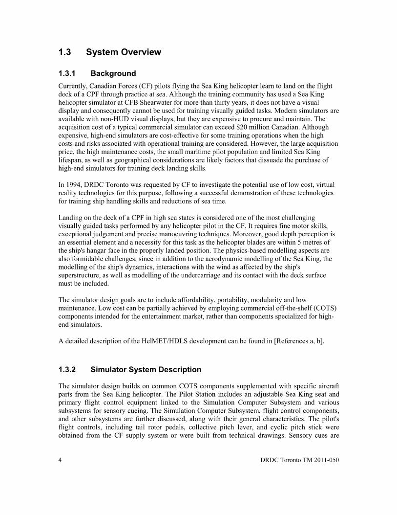
1.3 System Overview
1.3.1 Background Currently, Canadian Forces (CF) pilots flying the Sea King helicopter learn to land on the flight deck of a CPF through practice at sea. Although the training community has used a Sea King helicopter simulator at CFB Shearwater for more than thirty years, it does not have a visual display and consequently cannot be used for training visually guided tasks. Modern simulators are available with non-HUD visual displays, but they are expensive to procure and maintain. The acquisition cost of a typical commercial simulator can exceed $20 million Canadian. Although expensive, high-end simulators are cost-effective for some training operations when the high costs and risks associated with operational training are considered. However, the large acquisition price, the high maintenance costs, the small maritime pilot population and limited Sea King lifespan, as well as geographical considerations are likely factors that dissuade the purchase of high-end simulators for training deck landing skills. In 1994, DRDC Toronto was requested by CF to investigate the potential use of low cost, virtual reality technologies for this purpose, following a successful demonstration of these technologies for training ship handling skills and reductions of sea time. Landing on the deck of a CPF in high sea states is considered one of the most challenging visually guided tasks performed by any helicopter pilot in the CF. It requires fine motor skills, exceptional judgement and precise manoeuvring techniques. Moreover, good depth perception is an essential element and a necessity for this task as the helicopter blades are within 5 metres of the ship's hangar face in the properly landed position. The physics-based modelling aspects are also formidable challenges, since in addition to the aerodynamic modelling of the Sea King, the modelling of the ship's dynamics, interactions with the wind as affected by the ship's superstructure, as well as modelling of the undercarriage and its contact with the deck surface must be included. The simulator design goals are to include affordability, portability, modularity and low maintenance. Low cost can be partially achieved by employing commercial off-the-shelf (COTS) components intended for the entertainment market, rather than components specialized for high-end simulators. A detailed description of the HelMET/HDLS development can be found in [References a, b].
1.3.2 Simulator System Description
The simulator design builds on common COTS components supplemented with specific aircraft parts from the Sea King helicopter. The Pilot Station includes an adjustable Sea King seat and primary flight control equipment linked to the Simulation Computer Subsystem and various subsystems for sensory cueing. The Simulation Computer Subsystem, flight control components, and other subsystems are further discussed, along with their general characteristics. The pilot's flight controls, including tail rotor pedals, collective pitch lever, and cyclic pitch stick were obtained from the CF supply system or were built from technical drawings. Sensory cues are

DRDC Toronto TM 2011-050 5
provided by a visual subsystem, motion platform subsystem, and sound and vibration subsystems. Control of pilot training is conducted via the Instructor Operator Station and Audio communication Subsystem.
The simulator system block diagram is shown in Figure 2. The simulator consists of the following major subsystems [References a, b]:
• Motion Platform Subsystem
• Flight Control Component Subsystem
• Visual Subsystem
• Video Distribution Subsystem
• Sound Subsystem
• Vibration Subsystem
• Audio Communication Subsystem
• Simulation Computer Subsystem
• Instructor Operator Station Subsystem
• Landing Signals Officer Station Subsystem
• Local Area Network.
The Motion Platform Subsystem, a six-degree of freedom (DOF) motion base unit, provides the necessary motion cues (roll, pitch, yaw, heave, surge and sway) for a simulated helicopter.
The Flight Control Component Subsystem provides user control interfaces to three unique flight control characteristics: the vertical control, the horizontal control, and the heading control.
The Visual Subsystem provides the pilot with a view of simulated environment. It consists of a head tracking device, an image generator, and a head mounted display. The head tracking device determines the position and orientation of the pilot's head, which is used to determine his/her point of view. These measurements are passed to the image generator that renders the images within this field of view (FOV), and transmits the images to the Video Distribution Subsystem.

6 DRDC Toronto TM 2011-050
The Video Distribution Subsystem accepts display images in RGB video signals from the Image Generator and distributes images to the HMD display for pilot viewing and the instructor display repeater for instructor viewing.
The Sound Subsystem drives the sound and vibration subsystems’ speakers and delivers continuous auditory cues as a function of the Sea King's simulated flight regime based on data received from the Simulation Computer Subsystem.
Like the Sound Subsystem, the Vibration Subsystem provides continuous cues to supplement the Motion Platform Subsystem. The Vibration Subsystem is to provide the higher frequency vibration environments that are not normally provided through the Motion Platform Subsystem.
The Audio Communication Subsystem provides the necessary audio communication interfaces between the pilot and instructor-operator.
The Simulation Computer Subsystem executes the helicopter simulation model and management utilities, uses the pilot's controls to calculate the motion dynamics, determines the pilot's point of view from tracking head movements and generates the graphics for the pilot's visual display and the Instructor Operator Station repeater monitors.
The Instructor Operator Station communicates with the Simulation Computer Subsystem for the simulation control.
The Landing Signals Officer Station communicates with the Simulation Computer Subsystem for the simulation status and provides the Landing Signals officer with visual representation of the virtual scene. It also accepts input via the LSO console and provides this data to the simulation computer to update the simulation.
The Simulation Local Area Network provides communication among the five major computers (Motion Platform Control Computer, Simulation Computer, Instructor Computer, Landing Signals Officer Computer, Audio Communication Subsystem Computer 1 – Digital Audio Conferencing and Audio Communication Subsystem Computer 2 – Digital Audio Conferencing & Effects) that host the applications software for the simulation. The Audio Local Area Network provides communication between Audio Communication Subsystem Computer 1 – Digital Audio

DRDC Toronto TM 2011-050 7
Conferencing and Audio Communication Subsystem Computer 2 – Digital Audio Conferencing & Effects for hosting digital audio conference software.
Figure 2 Simulator Block Diagram
Video Signals
Flight Control Component Subsystem
Pilots Visual Subsystems
Vibration Subsystem
Video Distribution Subsystem
Video Signals
Audio Signals Serial
Inputs
Serial Inputs
Sound Subsystem
Audio Communication Subsystem
Landing Signals Officer Operator Station
Landing Signals Officer OPERATOR Visual Subsystems
Simulation Computer Subsystem
Instructor Operator Station
Motion Platform Subsystem
Simulation LAN
Microphone Report Cerealbox
Serial Inputs
Video Signals

8 DRDC Toronto TM 2011-050
1.4 Document Overview
This Software Product Specification (SPS) provides the inventory of software contents released and software support information. A brief outline of the contents of this document is given below:
Section 1 – Scope
This section describes the identification, system overview, and document overview for the simulator.
Section 2 – Referenced Documents
This section lists by document number, title, revision, and date all documents referenced in this document.
Section 3 – Requirements
This section lists the inventory of material released and software contents.
Section 4 – Software Support Information
This section provides information regarding installation procedures, compilation/build procedures, modification procedures, computer hardware resource utilization, and possible problems and known errors.
Section 5 - Notes
This section contains general information.
Appendices
The appendices provide information published separately for convenience in document maintenance. The appendices of this document consist of:
• Appendix A – Directory Structure
• Appendix B – SMART Makefile Structure
• Appendix C – MatrixX Notes on Sea King Simulator
• Appendix D – Modifications of Visual Models.

DRDC Toronto TM 2011-050 9
2 Referenced Documents
The following government and non-government documents are referenced in this manual:
a. DRDC Toronto Specification Helicopter Deck Landing Simulator & Landing Signalling Officer Simulator Preliminary Specification (Updated)
b. DRDC Toronto Technical Report Helicopter Deck Landing Simulator Technology Demonstrator by F.A. Lue and L.E. Magee
c. DRDC Toronto Technical Report Introduction to MultiGen Creator
d. DRDC Toronto Technical Report MultiGen Creator Modelling Techniques and Performance Optimization
e. DRDC Toronto Technical Report Developing Maintainable Code
f. DRDC Toronto Document: CR2002-027 Helicopter Maritime Environment Trainer Atlantis Document: ED990-01155 Software Test Description
g. DRDC Toronto Document: CR2002-022 Helicopter Maritime Environment Trainer Atlantis Document: ED997-00368 Operator Manual
h. DRDC Toronto Document: CR2002-028 Helicopter Maritime Environment Trainer Atlantis Document: ED997-00369 Maintenance Manual
i. DRDC Toronto Document: CR2002-031 Helicopter Maritime Environment Trainer Atlantis Document: VD905-03128 Version Description Document
j. DRDC Toronto Document: CR2002-032 Helicopter Maritime Environment Trainer Atlantis Document: ED999-01183 Data Package
k. Servos and Simulation Inc. Six Degrees Of Freedom Motion Platform Maintenance Manual
l. Bill Spitzak and others FLTK 1.0.10 Programming Manual
m. MathWorks Inc. MatrixX Online Documentation CD
n. MathWorks Inc. MatrixX CD-ROM Installation Procedure
o. MathWorks Inc. MatrixX Getting Started (Windows) Manual

10 DRDC Toronto TM 2011-050
p. MathWorks Inc. MatrixX System Administrator's Guide (Windows)
q. MathWorks Inc. MatrixX Autocode Application Notes
r. MultiGen Paradigm “Creating Models for Simulations, Version 2.4 for Windows and IRIX August 2000”, MultiGen Creator user manual, San Jose, CA
s. MultiGen Paradigm “Desktop Tutor”, MultiGen Creator user manual, San Jose, CA
t. MultiGen Paradigm “MultiGen Creator user manual, 3d Real-time simulation”, MultiGen Creator user manual, San Jose, CA

DRDC Toronto TM 2011-050 11
3 Requirements
3.1 Inventory of Material Released
The simulator software consists of the following two major Computer Software Configuration Items (CSCI):
•Support Software and Tools CSCI
•HelMET Operational Software CSCI.
Descriptions of these CSCIs can be found in the Helicopter Maritime Environment Trainer Operator Manual [Reference i].
The following sections describe the inventory of material released for these two CSCIs.
3.1.1 Support Software and Tools CSCI The Support Software and Tools CSCI, a collection of software packages, consists of the following major Computer Software Component (CSC):
• Purchased COTS CSC
• Freeware OTS CSC
• Customized OTS CSC
3.1.1.1 Purchased COTS
• MS-DOS Operating System (OS)
• OpenGL Performer for Linux
• RedHawk Linux Operating System (OS)
• CerealBox Driver.
3.1.1.1.1 MS-DOS Operating System
Table 1 lists the software material released for the MS-DOS Operating System:
Table 1 MS-DOS Operating System Inventory of Material Released
Part Number Media Title Media Type Duplication Licence - MS-DOS Operating System Version
6.22 1 3 2

12 DRDC Toronto TM 2011-050
(1) Media Types: (2) Duplication (3) Licence 1 – 3.5 inch, 1.44Mb DOS formatted floppy disk 1 – For backup purpose only 1 – N/A 2 – 8mm DAT, DOS formatted 2 – Unlimited 2 – Refer to Third Party contract 3 – Compact Disc 3 – Refer to 3rd party licence 4 – Downloaded from Internet
3.1.1.1.2 OpenGL Performer for Linux V3.1.1
lists the software material released for the OpenGL Performer for Linux:
Table 2: OpenGL Performer for Linux V3.1.1
Part Number Media Title Media Type Duplication Licence
- OpenGL Performer for Linux V3.1.1 3 3 2
(1) Media Types: (2) Duplication (3) Licence 1 – 3.5 inch, 1.44Mb DOS formatted floppy disk 1 – For backup purpose only 1 – N/A 2 – 8mm DAT, DOS formatted 2 – Unlimited 2 – Refer to Third Party contract 3 – Compact Disc 3 – Refer to 3rd party licence 4 – Downloaded from Internet
3.1.1.1.3 RedHawk Linux Operating System
lists the software material released for the Redhawk Linux Operating System:
Table 3: :RedHawk Linux Operating System
Part Number Media Title Media Type Duplication Licence
- RedHawk Linux Operating System V4.0 3 3 2
(1) Media Types: (2) Duplication (3) Licence 1 – 3.5 inch, 1.44Mb DOS formatted floppy disk 1 – For backup purpose only 1 – N/A 2 – 8mm DAT, DOS formatted 2 – Unlimited 2 – Refer to Third Party contract 3 – Compact Disc 3 – Refer to 3rd party licence 4 – Downloaded from Internet
3.1.1.1.4 CerealBox Driver

DRDC Toronto TM 2011-050 13
lists the software material released for the CerealBox Driver library.
Table 4 CerealBox Driver Inventory of Material Released
Part Number Media Title Media Type Duplication Licence
- CerealBox Driver v 307 3 3 2
(1) Media Types: (2) Duplication (3) Licence 1 – 3.5 inch, 1.44Mb DOS formatted floppy disk 1 – For backup purpose only 1 – N/A 2 – 8mm DAT, DOS formatted 2 – Unlimited 2 – Refer to Third Party contract 3 – CD (HelMET Operational SW CSCI) 3 – Refer to 3rd party licence 4 – Downloaded from Internet – http://www.bgsystems.com/
3.1.1.2 Freeware OTS CSC
The Freeware OTS CSC consists of the following major components:
• Red Hat Linux Operating System
• DMSO HLA Run-time Infrastructure (RTI)
• Parallel Virtual Machine (open source)
3.1.1.2.1 RedHat Linux Operating System
lists the software material released for the Linux Operating System:
Table 5 Linux Operating System Inventory of Material Released
Part Number Media Title Media Type Duplication Licence
- Linux RedHat Operating System Version 8.0
3 3 2
(1) Media Types: (2) Duplication (3) Licence 1 – 3.5 inch, 1.44Mb DOS formatted floppy disk 1 – For backup purpose only 1 – N/A 2 – 8mm DAT, DOS formatted 2 – Unlimited 2 – Refer to Third Party contract 3 – Compact Disc 3 – Refer to 3rd party licence 4 – Downloaded from Internet

14 DRDC Toronto TM 2011-050
3.1.1.2.2 DMSO HLA Run-time Infrastructure (RTI)
lists the software material released for the DMSO HLA RTI:
Table 6 DMSO HLA Run-time Infrastructure (RTI)
Part Number Media Title Media Type Duplication Licence
- HLA RTI 1.3 NGv6 3 3 2
1) Media Types: (2) Duplication (3) Licence 1 - 3.5 inch, 1.44Mb DOS formatted floppy disk 1 – For backup purpose only 1 – N/A 2 - 8mm DAT, DOS formatted 2 – Unlimited 2 – Refer to Third Party contract 3 - CD (HelMET Support SW CSCI) 3 – Refer to 3rd party licence 4 – Downloaded from Internet - http://sdc.dmso.mil/
3.1.1.2.3 Parallel Virtual Machine
lists the software material released for the Parallel Virtual Machine (PVM):
Table 7 PVM Inventory of Material Released
Part Number Media Title Media Type Duplication Licence
- Parallel Virtual Machine 3.4.3 3 3 2
1) Media Types: (2) Duplication (3) Licence 1 – 3.5 inch, 1.44Mb DOS formatted floppy disk 1 – For backup purpose only 1 – N/A 2 – 8mm DAT, DOS formatted 2 – Unlimited 2 – Refer to Third Party contract 3 – CD (HelMET Support SW CSCI) 3 – Refer to 3rd party licence 4 – Downloaded from Internet
3.1.1.3 Customized OTS
The Customized OTS CSC consists of the following major software packages. These packages have been customized to suit the needs of the simulator software.
• Motion Platform Control Computer Software
• FREDYN
• Fast Light Tool Kit

DRDC Toronto TM 2011-050 15
• Fast Light User Interface Designer
• Open Audio Library
3.1.1.3.1 Servos and Simulation Motion Platform Software
Table 8 lists the software material released for the Servos and Simulation Motion Platform Software:
Table 8 Motion Platform Software inventory of Material Released
Part Number Media Title Media Type Duplication Licence
83-0346-004 3Com EtherDisk Version 3.3 1 3 2
- FTP Software Inc PC/TCP Kernel v4.1 (K-210) Disk 1 of 1
1 3 2
- FTP Software Inc PC/TCP Kernel v4.1 (K-210) Disk 1 of 3
1 3 2
- FTP Software Inc PC/TCP Kernel v4.1 (K-210) Disk 2 of 3
1 3 2
FTP Software Inc PC/TCP Kernel v4.1 (K-210) Disk 3 of 3
1 3 2
- Servos and Simulation 6-DOF Software Disk
1 3 2
(1) Media Types: (2) Duplication (3) Licence 1 – 3.5 inch, 1.44Mb DOS formatted floppy disk 1 – For backup purpose only 1 – N/A 2 – 8mm DAT, DOS formatted 2 – Unlimited 2 – Refer to Third Party contract 3 – CD (HelMET Operational SW CSCI) 3 – Refer to 3rd party licence 4 – Downloaded from Internet
3.1.1.3.2 FREDYN
Table 9 lists the software material released for the FREDYN:
Table 9 FREDYN Inventory of Material Released
Part Number Media Title Media Type Duplication Licence

16 DRDC Toronto TM 2011-050
- Fredyn 6.0 3 3 2 (1) Media Types: (2) Duplication (3) Licence 1 – 3.5 inch, 1.44Mb DOS formatted floppy disk 1 – For backup purpose only 1 – N/A 2 – 8mm DAT, DOS formatted 2 – Unlimited 2 – Refer to Third Party contract 3 – CD (HelMET Operational SW CSCI) 3 – Refer to 3rd party licence 4 – Downloaded from Internet
3.1.1.3.3 Fast Light Tool Kit
Table 10 lists the software material released for the Fast Light Took Kit (FLTK):
Table 10 FLTK Inventory of Material Released
Part Number Media Title Media Type Duplication Licence
- FLTK 1.0.10 3 3 2 (1) Media Types: (2) Duplication (3) Licence 1 – 3.5 inch, 1.44Mb DOS formatted floppy disk 1 – For backup purpose only 1 – N/A 2 – 8mm DAT, DOS formatted 2 – Unlimited 2 – Refer to Third Party contract 3 – CD (HelMET Support SW CSCI) 3 – Refer to 3rd party licence 4 – Downloaded from Internet
3.1.1.3.4 Fast Light User Interface Designer
Table 11 lists the software material released for the Fast Light User Interface Designer (FLUID):
Table 11 FLUID Inventory of Material Released
Part Number Media Title Media Type Duplication Licence
- FLUID v1.0.9 + DRDC patch 04 3 3 2 (1) Media Types: (2) Duplication (3) Licence 1 – 3.5 inch, 1.44Mb DOS formatted floppy disk 1 – For backup purpose only 1 – N/A 2 – 8mm DAT, DOS formatted 2 – Unlimited 2 – Refer to Third Party contract 3 – CD (HelMET Operational SW CSCI) 3 – Refer to 3rd party licence 4 – Downloaded from Internet
3.1.1.3.5 Open Audio Library
Table 12 lists the software material released for the Open Audio library (OpenAL):
Table 12 OpenAL Inventory of Material Released
Part Number Media Title Media Type Duplication Licence

DRDC Toronto TM 2011-050 17
- Open Audio Library (12 Feb 01) 3 3 2
(1) Media Types: (2) Duplication (3) Licence 1 – 3.5 inch, 1.44Mb DOS formatted floppy disk 1 – For backup purpose only 1 – N/A 2 – 8mm DAT, DOS formatted 2 – Unlimited 2 – Refer to Third Party contract 3 – CD (HelMET Support SW CSCI) 3 – Refer to 3rd party licence 4 – Downloaded from Internet - http://www.openal.org/
3.1.2 HelMET Operational Software CSCI
3.1.2.1 Software Development Tools
Some of non-deliverable software development tools include:
• MATRIXx
• MultiGen Creator
3.1.2.1.1 MATRIXx
lists the software material released for the MATRIXx.
Table 13 MATRIXx Inventory of Material Released
Part Number Media Title Media Type Duplication Licence
090-0017-007 MATRIXx 6.2.2 for NT4.0 3 3 2
(1) Media Types: (2) Duplication (3) Licence 1 – 3.5 inch, 1.44Mb DOS formatted floppy disk 1 – For backup purpose only 1 – N/A 2 – 8mm DAT, DOS formatted 2 – Unlimited 2 – Refer to Third Party contract 3 – Compact Disc 3 – Refer to 3rd party licence 4 – Downloaded from Internet
3.1.2.1.2 MultiGen Creator
lists the software material released for the MultiGen Creator.

18 DRDC Toronto TM 2011-050
Table 14 MultiGen Creator Inventory of Material Released
Part Number Media Title Media Type Duplication Licence
- MultiGen Creator Visual Data Base Modelling System, Version 2.4.1 OpenFlight
Version 15.70
3 3 2
(1) Media Types: (2) Duplication (3) Licence 1 – 3.5 inch, 1.44Mb DOS formatted floppy disk 1 – For backup purpose only 1 – N/A 2 – 8mm DAT, DOS formatted 2 – Unlimited 2 – Refer to Third Party contract 3 – Compact Disc 3 – Refer to 3rd party licence 4 – Downloaded from Internet

DRDC Toronto TM 2011-050 19
4 Software Support Information
4.1 Related Documents TM 2011-048 Helicopter Maritime Environment Trainer Software Test Document
TM 2011-047 Helicopter Maritime Environment Trainer Operator Manual
TM 2011-049 Helicopter Maritime Environment Trainer Maintenance Manual
TM 2011-051 Helicopter Maritime Environment Trainer Version Description Document
TM 2011-052 Helicopter Maritime Environment Trainer Data Package
4.2 Installation Instructions
4.2.1 Commercial Off-the-Shelf CSCI Installation Instructions
4.2.1.1 MS-DOS Operating System
The MS-DOS 6.22 runs on a 100 MHz Pentium Single Board Computer (SBC) for the 6-DOF Motion Platform.
Information on installing the OS is described in the MS-DOS 6.22 Installation Manual.
4.2.1.2 Red Hat Linux Operating System
Red Hat Linux 8.0 runs on Intel X86 computers for the IOS, LSO, Audio Subsystem Computer1 and Audio Subsystem Computer2.

20 DRDC Toronto TM 2011-050
Information on installing the OS is described in the Official Red Hat Linux 8.0 Installation Guide which is available and downloadable from www.redhat.com. Further information is available in the RH8.pdf file on the HelMET Support Software Install CD for Linux.
4.2.1.3 RedHawk Linux Operating System
The RedHawk Linux 4.0 runs on a Concurrent Computer Corporation Imagen Computer system which houses 4 Dual core AMD processors that is used as the simulation computer.
Information on installing the OS is described on the Redhawk Installation CDs.
4.2.1.4 DMSO HLA Run-time Infrastructure (RTI)
The HLA RTI Next Generation 1.3 (RTI-NG 1.3) from Defence Modelling Simulation Organization (DMSO) and Science Application International Corporation (SAIC) is an implementation of the High Level Architecture Specification, Version 1.3. The RTI provides a collection of common services used to support the modelling and simulation applications. All of these services are accessed through a standard application programming interface (API).
The HLA RTI is included in the HelMET Support Software Installation CD. Information on installing the HelMET Operational Software CSCI is described in the RH8.pdf file on the HelMET Support Software Install CD for Linux.
4.2.1.5 OpenGL Performer for Linux 3.1.1
OpenGL Performer is proprietary 3D Graphics rendering Software from Silicon Graphics International (SGI). this software runs on all HelMET computers that display images from the Virtual World (Simulation, IOS, and LSO computers).
Information on installing the HelMET Operational Software CSCI is described in the RH8.pdf file on the HelMET Support Software Install CD for Linux.
4.2.1.6 CerealBox Driver
The Cereal Box Driver Library, from BG Systems Inc, provides the necessary functions to configure and interface with the CerealBox hardware.
The CerealBox driver is included in the HelMET Operational Software CSCI CD. Information on installing the HelMET Operational Software CSCI is described in the RH8.pdf file on the HelMET Support Software Install CD for Linux.

DRDC Toronto TM 2011-050 21
4.2.1.7 Open Audio Library
The Open Audio Library (OpenAL), a free distribution software package from Loki Entertainment Software, is an Application Programming Interface (API) for interactive, primarily spatialized audio.
The Open Audio library is included in the HelMET Support Software Install CD. Information on installing the HelMET Operational Software CSCI is described in the RH8.pdf file on the HelMET Support Software Install CD for Linux.
4.2.1.8 Parallel Virtual Machine
The Parallel Virtual Machine (PVM), a free distribution software package from Oak Ridge National Laboratory, allows a computer to spawn processes on another computer.
The Parallel Virtual Machine is included in the HelMET Support Software CSCI CD. Information on installing the HelMET Operational Software CSCI is described the RH8.pdf file on the HelMET Support Software Install CD for Linux.
4.2.1.9 Servos and Simulation Motion Platform Software
The Motion Platform Control Computer Subsystem is an IBM Compatible PC, which is equipped with the following system environments:
1. Hardware Environment
A 100 MHz Pentium Single Board Computer (SBC) mounted in slot 1 of the passive backplane chassis
A 8 Mbytes of ram memory
One 3.5 inch Hard Disk Drive and one 3.5 inch floppy disk drive
One VGA Display Monitor
One standard keyboard
One RS-232 serial port
One Centronics parallel port
One CIO-DDA06/12 Digital I/O board for communicating with the SBC
One CIO-RELAY08 Relay board.
2. Software Environment

22 DRDC Toronto TM 2011-050
Microsoft MS-DOS version 6.22
An Ethernet packet driver for the specified Ethernet card
FTP Software PC/TCP for DOS software
Servos and Simulation Incorporation’s 6-DOF software disk.
The following steps must be performed to install the software of the Motion Platform Control Computer Subsystem. Additional information on the software of the Motion Platform Control Computer Subsystem is described in the Six Degrees of Freedom Motion Platform Maintenance Manual [Reference k]
1. Set computer’s BIOS to a standard setup, disabling the cache where the Ethernet card resides (not necessary on plug and play cards).
2. Format hard drive using MS-DOS 6.22 and install operating system in the C:\DOS subdirectory.
3. Install the 6-DOF software with the following command from the DOS prompt:
XCOPY A:\*.* C:\*.* /s/e/v
4. Install the Ethernet card’s supporting software with its packet-drive support files.
5. Install FTP’s PC/TCP for DOS.
6. Setup the network using PC/TCP’s provided configuration manager.
7. Add the ‘;C:\6DOF;’ to your path in the autoexec.bat.
8. Add ‘Go’ as the last line in the autoexec.bat.
9. Reboot the machine to start the system.
10. Edit C:\6DOF\GO.BAT to reflect the host’s IP address and port number.
11.
4.2.1.10 FREDYN
The FREDYN Version 6.0 from Maritime Research Institute Netherlands (MARIN) is a software package used for the ship dynamics within the simulator.
DRDC Toronto TM 2011-050 23
The Fredyn software is included in the HelMET Operational Software CSCI CD. Information on installing the HelMET Operational Software CSCI is described in the RH8.pdf file on the HelMET Support Software Install CD for Linux.
4.2.1.11 Fast Light Tool Kit
The Fast Light Tool Kit (FLTK), a free distribution software package, is used to provide the necessary GUI for controlling the simulation exercise.
The Fast Light Tool Kit is included in the HelMET Support Software CSCI CD. Information on installing the HelMET Operational Software CSCI is described in the RH8.pdf file on the HelMET Support Software Install CD for Linux.
4.2.1.12 Fast Light User Interface Designer
The Fast Light User Interface Designer (FLUID), a free distribution software package, is a graphical editor that is used to produce FLTK source code. The FLUID editor can be used to edit and save its state in FLUID (.fl) files.
The Fast Light User Interface Designer is included in the HelMET Support Software CSCI CD. Information on installing the HelMET Operational Software CSCI is described in the RH8.pdf file on the HelMET Support Software Install CD for Linux.
4.2.1.13 MATRIXx
The MATRIXx 6.2.2 from MathWorks Inc. is a suite of development tools for modelling Sea King aerodynamics. The MATRIXx is installed in a NT4.0 environment.
Information on installing MATRIXx 6.2.2 is described in the MATRIXx Installation Manual.
4.2.1.14 MultiGen Creator
The MultiGen Creator Visual Data Base Modelling System from MultiGen Paradigm is a software toolset for creating a highly optimised, high-fidelity, real-time 3D database for use in visual simulation, interactive games, urban simulation, and other applications.

24 DRDC Toronto TM 2011-050
Information on installing MultiGen Creator is described in the MultiGen Creator Getting Started manual.
4.2.2 HelMET Operational Software CSCI Installation Instructions
Descriptions of the HelMET Operational Software CSCI can be found in the Helicopter Maritime Environment Trainer Operator Manual [Reference i].
Information on installing HelMET Operational Software CSCI is described in the Helicopter Maritime Environment Trainer Operational Software CSCI Version Description Document [Reference k].
4.3 Compilation/Build Procedures
The HelMET Operational Software CSCI runs in the LINUX environment. The following sections describe the compilation/build environment and process for the HelMET Operational Software CSCI.
4.3.1 Compilation/Build Environment
4.3.1.1 Compilation/Build Environment On LINUX
The version of HelMET Operational Software CSCI requires the following system environment to be able to compile/build in a LINUX environment:
Hardware Environment:
• IBM Compatible PC:
Intel Pentium computer (or equivalent)
at least 512 MB RAM
(Audio computers only) Creative Labs Sound Blaster Live sound card
Nvidia GeForce 2 or newer
NIC
CD-ROM drive or FTP client
40 GB Hard Drive or better.

DRDC Toronto TM 2011-050 25
Software Environment:
Table 15 Compilation/Build Software Environments on LINUX
Part Number Media Title Media Type
Duplication Licence Web Site
- RedHat Linux 8.0 or Redhawk Linux
3 3 2 http://www/redhat.com
- The Fast Light Toolkit fltk 1.0.10
3 3 2 http://www.fltk.org
- Fast Light User Interface Designer
fluid 1.0.9
3 3 2 http://www.fltk.org
- Open Audio Library OpenAL
(12 Feb 01)
3 3 2 http://www.openal.org
- Parallel Virtual Machine pvm 3.4.3
3 3 2 http://www.csm.ornl.gov/pvm/pvm_home.html
- OpenGL Performer V3.1.1
3 3 2 http://www.sgi.com
- DMSO HLA RTI 1.3 NGv6
3 3 2 http://sdc.dmso.mil/ (out of date)
(1) Media Types: (2) Duplication (3) Licence 1 - 3.5 inch, 1.44Mb DOS formatted floppy disk 1 – For backup purpose only 1 – N/A 2 - 8mm DAT, DOS formatted 2 – Unlimited 2 – Refer to Third Party contract 3 - CD (HelMET Operational SW CSCI) 3 – Refer to 3rd party licence 4 – Download from Internet
4.3.2 Compilation/Build Process
The software source code is compiled/built using the linux (gmake) make utility. The linux gmake utility is a tool for organizing and facilitating the update of executables or other files that are built from one or more constituent files. The make execution command uses the user-defined

26 DRDC Toronto TM 2011-050
Makefile to create or update one or more target files based on the most recent modify dates of the required files. This Makefile provides instructions on how source files are compiled. When the make command is executed, it looks for a Makefile in the current directory. If a Makefile cannot be found, the make command will look for other filename such as makefile. (However, to make the build process be consistent, the filename Makefile is always used throughout the project). In the case that the command cannot locate a Makefile, the make process will fail and a message similar to “No targets specified and not makefile found” will be displayed.
In the software, the compilation/build process is further enhanced with the use of the build script. The build script is provided with a variety of options for the user to choose during compilation/build process. The options are detailed as follows:
• build clean – clean out savdb, smart, rhs and all hdls federates and builds from scratch
• build all – build savdb, smart and rhs libraries and helo, lso and ios, drdc_helo federates and audio_server (executable)
• build savdb clean – clean out savdb libraries and then builds savdb
• build savdb – build savdb libraries
• build smart clean – clean out smart libraries and then build smart libraries
• build smart – build smart libraries
• build rhs clean – clean out all hdls federates and then build rhgs librarries and all federates
• build rhs – build rhs librarries and all federates
• build helo – build Helo Federate
• build ios – build ios Federate
• build lso – build lso Federate
When the build script is invoked, it will call upon make command with appropriate Makefiles that define rules for making target files. The software directory structure is described in Appendix A of this document. Note that in each of the source directories, there is a user-defined Makefile.
An overview of the software Makefile structure is described in Appendix B of this document.
4.3.2.1 Illustration of Build Process
The process of building SMART library is used here for illustration purpose only. When a command “build smart” is entered in the command line, the build script executes make command which calls upon the Makefile file in the ~/local/smart/src directory. This Makefile defines all sub-directories to be made and includes the SMART_makedirs.mk for the rules to make these sub-directories.

DRDC Toronto TM 2011-050 27
The SMART_makedirs.mk file loops through the subdirectories calling make with the Makefile in each of the subdirectories. The Makefile in each sub-directory defines the rules and target / stub to be built. Each target or stub is associated with a .mk file. The individual .mk file defines the library name and object files to be built. It also contains definition and information on how to process the build requests to create a binary executable, a static library, a dynamic library or object files.
The individual .mk file also includes the SMART_makelibdefs.mk and SMART_makelib.mk files. The SMART_makelibdefs.mk file defines the locations of the object (.o) and dependency (.d) directories. It also includes the SMART_defs.mk and SMART_libs.mk files. The SMART_defs.mk defines all compilation utilities, shell commands and compiler flags. The SMART_lib.mk defines variables for the standard system libraries and all smart libraries provided by the SMART.
The SMART_makelib.mk includes the SMART_makestaticlib.mk file. The SMART_makestaticlib.mk file defines rules for making the SMART library and also includes the SMART_sources.mk, SMART_deps.mk and SMART_rules.mk files which define the rules for building the source, dependency and object files.
The following tree diagram illustrates the process of building the SMART library:
build smart
Makefile (local/smart/src) SMART_makedirs.mk Makefile (in each subdirectory, e.g. DataTree, Performer, etc) SMART_maketargets.mk (for each individual .mk file) SMART_makelibdefs.mk SMART_defs.mk SMART_defslinux.mk SMART_libs.mk

28 DRDC Toronto TM 2011-050
SMART_makelib.mk SMART_makestaticlib.mk SMART_sources.mk SMART_deps.mk SMART_rules.mk
4.3.2.2 Compilation/Build Process On LINUX
4.3.2.2.1 Setting Up Build Machine
Assuming that the build machine has had RedHat linux 8.0 previously installed. The procedure for setting up Build Machine is described below:
1. Log on to the computer as root.
2. Insert the “HelMET Support Software Install CD for LINUX” into the CD_ROM drive. Make a mount point for the cdrom. i.e. mkdir /mnt/cdrom. Mount the cdrom i.e. mount /dev/hdc /mnt/cdrom
3. Open a console window and type “tar -xvf /mnt/cdrom/RH8_Setup.tar” and then press Enter.
4. Type “cd RH8” and press Enter.
5. Type “tcsh configure_system.csh”
6. Follow the on-screen instructions. This installation will take over 10 minutes to complete. The installation will install PVM, openal, fltk, fluid, the RTI and OpenGL Performer with a demo license.. Note that it is assumed that LINUX has already been installed. Refer to Section Compilation/Build Environment On LINUX for information on Compile/Build Environment on LINUX.
7. Unmount the cdrom “umount /mnt/cdrom” and insert the “HelMET Operational Software Install CD”. Mount this CD as above.
8. logout.
9. Log in as vrsim with password being sea_king.

DRDC Toronto TM 2011-050 29
10. Open a console window and type “tar -zxvf /mnt/cdrom/hdls.tgz” and then press Enter.
4.3.2.2.2 Compiling/Building Source Code on LINUX
The following sections describe compiling/building source code on LINUX..
4.3.2.2.2.1 Cleaning All Executables and Object Files
The procedure for cleaning all executables and object files is described below:
1. Log in as vrsim with password being sea_king.
2. Open a console window and type “build clean”.
4.3.2.2.2.2 Cleaning the Entire smart Directory
The procedure for cleaning the entire smart directory is described below:
1. Log in as vrsim with password being sea_king.
2. Open a console window and type “cd local”.
3. Then switch to a directory that you want to clean by typing “cd smart/src”.
4. Finally type “make clean”.
5. “type cd ../..”
6. Repeat steps 3 through 5 for the rhs/src and savdb/src directories.
4.3.2.2.2.3 Cleaning Specific Subdirectories Inside smart directory
The procedure for cleaning specific subdirectories inside hdls, smart, or savdb directories is described below:
1. Log in as vrsim with password being sea_king.

30 DRDC Toronto TM 2011-050
2. Open a console window and type “cd local”.
3. Then switch to a directory that you want to clean. For example, to clean the Performer executables and object files located in ~/local/smart/src/Performer, type “cd smart/src/Performer”.
4. Finally type “make clean”.
4.3.2.2.2.4 Full Build
The procedure for performing a full build is described below:
1. Log in as vrsim with password being sea_king.
2. Then type “build all”.
4.3.2.2.2.5 Building the Entire smart Directory
The procedure for building the entire smart directory is described below:
1. Log in as vrsim with password being sea_king.
2. Open a console window and type “cd local”.
3. Then switch to a directory that you want to build by typing “cd smart/src”.
4. Finally type “make”.
4.3.2.2.2.6 Building a Specific Subdirectory
The procedure for building a specific subdirectory inside the smart directory:
1. Log in as vrsim with password being sea_king.
2. Open a console window and type “cd local/smart/src”.

DRDC Toronto TM 2011-050 31
3. Then switch to a directory that you want to build. For example, to build the CerealBox source code located in ~/local/smart/src/CerealBox, type “cd CerealBox”.
4. Finally type “make”.
4.4 Modification Procedures
The following sections describe the modification environment and process for the HelMET Operational Software CSCI.
4.4.1 Modification Environment
4.4.1.1 Modification Environment On LINUX
The version of HelMET Operational Software CSCI requires the following system environment:
Hardware Environment - Refer to Section Compilation/Build Environment On LINUX
Software Environment - Refer to Section Compilation/Build Environment On LINUX
4.4.2 Modification Process
4.4.2.1 Modification Process on Linux
4.4.2.1.1 Graphic User Interface Modification
The simulator Graphic User Interface (GUI) is developed using the Fast Light Tool Kit (FLTK) Version 1.0.11. The FLTK is a Free Distribution Software package. The source code of GUI is created using the Fast Light User Interface Designer (FLUID) graphical editor. FLUID edits and saves its state in .fl files. These files are in text file format, which can be edited with care with a

32 DRDC Toronto TM 2011-050
text editor. However, the most efficient and safest way to edit the .fl files is to use the FLUID graphical editor.
The following steps describe how to edit a FLUID .fl file:
1. Type “fluid <filename>.fl”
e.g.: fluid DLPEditorWindow.fl
2. A FLUID graphical editor is opened with the file DLPEditorWindow.fl loaded.
3. The user can now edit or create widgets. Further information on using FLTK can be found in the FLTK1.0.11 Programming Manual [Reference n].
4. Once the edition is completed, the user can save the changes and close the FLUID editor.
The following steps describe how to compile a FLUID .fl file:
1. Type “fluid –c <filename>.fl”
e.g.: fluid –c DLPEditorWindow.fl
2. The FLUID “compiler” is called to read the DLPEditorWindow.fl and write the DLPEditorWindow.hpp and DLPEditorWindow.cpp files. If there are any errors reading or writing the files, it will print the error and exit with a non-zero code.
Once the .hpp and .cpp files have been updated/created, the source code can be compiled. The GUI library can then be built by invoking the “make” command in the GUI directory.
The “make” command will also automatically generate the .cpp and .hpp files when it detects that the .fl file has a date newer than .cpp and .hpp files

DRDC Toronto TM 2011-050 33
4.4.2.1.2 MatrixX Sea King Aerodynamic Model Modification
The MatrixX 6.2.2 from MathWorks Inc. is a suite of development tools for modelling Sea King aerodynamics. To create a Sea King helicopter aerodynamic model with clearly delineated modules, the physical model must be implemented using the MatrixX software package. The package is designed for simulating dynamic system and can auto-generate C code for use in a real-time man-in-the-loop helicopter simulation.
The current Sea King simulation model has been developed by the University of Toronto Institute of Aerospace Studies (UTIAS) and implemented in MatrixX using its SysemBuild software. The Sea King model C-code, which is generated using MatrixX’s AutoCode feature, is integrated into simulator C++ code for use in a real time environment.
Further information on basic functions of MatrixX and simple model manipulation can be found in Appendix C “MatrixX Notes – Sea King Simulator”. These notes are designed to serve as an introduction to users who would use the MatrixX to modify the Sea King Simulator.
NOTE
Since the MatrixX - Sea King Aerodynamics Model, the core of the simulator, is a piece of complex software, it must be emphasized that only a person with an in-depth knowledge of aerodynamics and the MatrixX software package is allowed to perform the modification or enhancement of the Sea King Aerodynamics Model code.
4.4.2.1.3 Visual Modelling Modification
The MultiGen Creator from MultiGen Paradigm is a software toolset for creating a highly optimized, high-fidelity, real-time 3D database for use in visual simulation. There are two visual models in the simulator, the CPF and the Sea King helicopter. Both of these 3D objects are modelled using MultiGen Creator.
Information on maintaining and upgrading the simulator visual models can be found in Appendix D “Modifications of Simulator Visual Models”. These notes are designed to serve as an introduction to users who would use MultiGen Creator to maintain and upgrade the simulator visual models.

34 DRDC Toronto TM 2011-050
NOTE
Since the maintenance of the simulator visual models, the CPF and the Sea King helicopter, is not a trivial task to perform, it must be emphasized that only a person with knowledge of using MultiGen Creator and the concept of a visual database is allowed to perform the modification or enhancement of the simulator visual models.
4.4.2.1.4 FREDYN Ship Dynamics Modification
FREDYN is a software package used for the ship dynamics within the simulator. Developed, in part by the Maritime Research Institute Netherlands (MARIN), and supported locally by DRDC-Atlantic, the FREDYN software library is written in Fortran. The version of the library that is used in the simulator is a modified implementation of the version 6.0.
FREDYN interacts with other helper utilities such as FREINP, which generates required data files. Before being able to generate ship motion, FREDYN requires a number of different data files such as a file that describes the ship geometry.
There are two aspects to the FREDYN library. First there is the actual Fortran code base that performs the dynamic modelling of the ship within a dynamic environment. Secondly there is an interface, written in C++, that facilitates real-time integration of the software library into other applications, such as the simulator.
Compilation is done with the SGI MIPSpro F77 Fortran compiler. The invocation of the compiler is through the standard “make” process. To compile changes to the FREDYN library into other applications, it is required to first generate a static library. This is done by generating the necessary object files using an F77 Fortran compiler in addition to compiling the C interface code. These objects can then be linked together to form a static library in the same way as the rest of the code in the simulator. A higher-level interface to the FREDYN code is provided in ShipDynamics class. This facilitates the encapsulation of the FREDYN library within a higher level construct.
NOTE
Modifying the FREDYN library should be limited to critical bug fixes because of the complexity of the software.

DRDC Toronto TM 2011-050 35
4.4.2.1.5 C++ Source Code Modification
The simulator Operational Software CSCI is designed using an Object Oriented Design approach and its source code is implemented using the C++ programming language. Throughout the coding phase of the simulator development life cycle, certain coding guidelines such as naming conventions have been adopted. The coding guidelines that are used in this simulator project are documented in the DRDC Toronto document “Developing Maintainable Code” [Reference f].
When modifying the simulator C++ code, care should be taken to follow the coding guidelines that have been followed in this project. By doing so, the source code can be sustainable as well as reusable.
Changes to the source code can be performed using any text editor. However, it is recommended that a screen-based editor vi editor be used, as it is very common in the Unix world and also it provides power features to aid programmers.
Once the changes have been completed and saved, they can be compiled / built using the procedures described in Section Compilation/Build Procedures.
4.5 Creating Installation CD Procedures
4.5.1 Creating Installation CD for LINUX
The following steps must be performed to create an installation CD for HelMET Operational Software CSCI on a LINUX environment:
1. Log in as vrsim with password being sea_king.
2. Copy the contents of the previous HelMET Operational Software CSCI Install CD for LINUX to a temporary directory tmp_linux on the LINUX development computer.
3. Verify that the “local” Directory contains the source code that a CD is to be created.

36 DRDC Toronto TM 2011-050
4. Type “tar -zcf hdls.tgz local”
5. Copy the zipped files hdls.tgz to the temporary directory tmp_linux.
6. Burn the contents of the directory tmp_linux onto a new blank CD.
7. Test the newly created CD, using the procedures described in the Helicopter Maritime Environment Trainer Operational Software CSCI Version Description Document [Reference i]
4.6 Computer Hardware Resource Utilization
Not applicable.
4.7 Possible Problems and Known Errors
Information on the possible problems and known errors is described in the Helicopter Maritime Environment Trainer Operational Software CSCI Version Description Document [Reference k].

DRDC Toronto TM 2011-050 37
5 Notes
5.1 Abbreviations and Acronyms
Item Descriptions
API Application Programming Interface
CD Compact Disk
CD-ROM Compact Disk Read Only Memory
CF Canadian Forces
CFB Canadian Forces Base
COTS Commercial Off The Shelf
CPF Canadian Patrol Frigate
CPU Central Processing Unit
CSC Computer Software Component
CSCI Computer Software Configuration Item
Dias The operator or person controlling the VR Simulator
DMSO Defence Modelling Simulation Organization
DOF Degrees of Freedom

38 DRDC Toronto TM 2011-050
DOS Disk Operating System
DRAM Dynamic Random Access Memory
DRDC Defence R&D Canada
FLTK Fast Light Tool Kit
FLUID Fast Light User Interface Designer
FOV Field of View
FTP File Transfer Protocol
GB Gigabytes
GUI Graphical User Interface
HDLS Helicopter Deck Landing Simulator
HelMET Helicopter Maritime Environment Trainer
HLA High Level Architecture
HMD Head Mounted Display
HUD Head Up Display
IBM International Business Machines

DRDC Toronto TM 2011-050 39
IOS Instructor Operator Station
KB Kilobytes
LAN Local Area Network
LOD Level of Detail
MARIN Maritime Research Institute Netherlands
MB Megabytes
MHz Mega Hertz
MS-DOS Microsoft Disk Operating System
NIM Network Interface Module
N/A Not Applicable
NIC Network Interface Card
OS Operating System
PC Personal Computer

40 DRDC Toronto TM 2011-050
PVM Parallel Virtual Machine
RAM Random Access Memory
RGB Red Green Blue
RHS Reconfigurable helicopter Simulator
RPM Rotation Per Minute
RTI Run Time Infrastructure
SAIC Science Application International Corporation
SBC Single Board Computer
SGI Silicon Graphics Inc.
SMART Simulation Modeling Acquisition Rehearsal Training
SPS Software Product Specification
SW Software
TCP Transmission Control Protocol
UCL University College London
UTIAS University of Toronto Institute of Aerospace Studies

DRDC Toronto TM 2011-050 41
UPS Uninterruptible Power Source
VGA Video Graphics Adapter
VLP Virtual Lesson Plan
VR-Sim Virtual Reconfigurable Simulator

42 DRDC Toronto TM 2011-050

DRDC Toronto TM 2011-050 43
Annex A Simulator Software Directory Structure
A.1 Simulator Software Directory Structure
Directories marked with (dyn) are dynamically created in some automatic or semi-automatic way. They may or may not exist or have any appreciable content.

44 DRDC Toronto TM 2011-050
Level 0
Level 1 Level 2 Level 3 Level 4 Level 5 Level 6
local/ config/ shearwater/ rhs/ bin/ Linux/ docs/ html/ (dyn) hdls/ config/ shearwater/ DRDC/ config/ icons/ logs/ mission_plans/ profiles/ resources/ tmp/ icons/ (N/A) logs/ flyco/ helo/ ios/ lso mission_plans/ profiles/ scripts/ tmp/ vlp/ include/ lib/ Linux/ mods/ Linux/ scripts/ src/ Apps/ HDLS deps/ (dyn) DRDC/ deps/ (dyn) objs/ (dyn) apps.mk Entities/ BaseEntity/ Bridge/ CPF/ DeckCrew/ FLYCO/ LandEnv/ LSO/ NFC/ Pilot/ Referee/ SeaEnv/ SeaKing/ SeaKingNFC/ TerrainEnv/ GUI/ AppsGUI/ DRDCHelo/ HDLS

DRDC Toronto TM 2011-050 45
Level 0
Level 1 Level 2 Level 3 Level 4 Level 5 Level 6
BaseGUI/ images/ BaseLargeGUI/ DeviceGUI/ EntityGUI/ images/ include/ OptionsGUI/ ScenarioGUI/ DLPScenario images/ HAMScenario images/ mains.mk Makefile RHS-Core/ Base-Entities/ Environment/ Observer/ Scenario/ GUI-Core/ include/ Kernel/ Streams/ Clients/ Profiles/ Sources/ Utils/ Views/ Scenarios/ DLPScenario/ HAMScenario/ Utils/ smart/ bin/ Linux/ data/ CPF/ docs/ html/ include/ lib/ scripts/ src/ Apps/ CerealBoxGUI/ Fredyn/ CDAWSP/ CPF/ FREAN/ FREINP/ RUN/ HDLReader/ LineViewer/ LogAnalysis/ PerfViewer/ PlatformGUI/ SceneMaker/ SMDGenerator/ TrackerGUI/ TrackerTools

46 DRDC Toronto TM 2011-050
Level 0
Level 1 Level 2 Level 3 Level 4 Level 5 Level 6
Audio/ AudioComm/ CerealBox/ lv3/ DataTree/ Debug/ Dynamics/ Helo/ GenHel MatrixX Sea/ Ship/ fredyn/ CDAWSP/ CPF/ FREAN/ FREDYN/ FREINP/ RUN/ ShipMo3D/ SampleData/ SampleLogs/ FileIO/ Filters/ Kalman/ IPME/ NIM/ PVM/ Performer/ Platform/ MotionBase/ PlatformServer/ MotionBase/ Record/ SerialPort/ SmartFltk/ Socket/ Thread/ Tracker/ Utils/ savdb/ data/ CPF/ docs/ html/ include/ lib/ Linux/ models/ ADS33/ src/ textures/ CPF/ src/ textures/ DeckCrew/ src/ hdls Ocean/ src/ textures/ SeaKing adf/
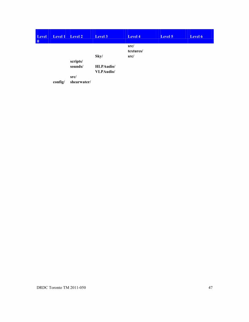
DRDC Toronto TM 2011-050 47
Level 0
Level 1 Level 2 Level 3 Level 4 Level 5 Level 6
src/ textures/ Sky/ src/ scripts/ sounds/ HLPAudio/ VLPAudio/ src/ config/ shearwater/

48 DRDC Toronto TM 2011-050
Annex B SMART Makefile Structure
B.1 SMART Makefile Structure
This document provides a brief overview of the SMARTMakefile structure.
SMART Makefiles
The following makefiles provide common rules and variable declarations for building SMART libraries.
Makefile Description SMART_defs.mk variable declarations common to all makefiles SMART_defsLinux.mk variable declarations specific to Linux SMART_deps.mk includes a *.d dependency file for every *.o object file,
and specifies rules for building *.d dependency files SMART_libs.mk variable declarations for library names and locations SMART_rules.mk common rules for building .o files SMART_sources.mk common rules for building .cpp and .hpp source files SMART_makedirs.mk rule for recursing through and building subdirectories SMART_maketargets.mk rule for calling a series of specified makefiles within
a directory SMART_makebin.mk rule for building an target executable SMART_makebindefs.mk includes defs required for building an executable SMART_makelib.mk obsolete - use SMART_makestaticlib.mk or
SMART_makedynamiclib.mk SMART_makelibdefs.mk includes defs required for building a library SMART_makestaticlib.mk: rule for building a target static library (archive) SMART_makedynamiclib.mk rule for building a target dynamic library (shared object) SMART_makemod.mk rule for building a mod (object files) defined in the OBJS
environment variable. SMART_makemoddefs.mk includes defs required for building a mod

DRDC Toronto TM 2011-050 49
B.2 Definitions of mods, bins, libs and ii_files
mods, bins, libs and ii_files are the four types of targets supported by the SMART makefiles.
lib:
A collection of object files bound together into a single file. A lib can be either a static archive (.a) or a dynamic shared object (.so).
bin:
An executable program.
mod:
A collection or grouping of object files. mods are useful in separating different components of a project without having to resort to libraries. Project A may use mod X and Y, while Project B can use mod Y and Z.
ii_files
The ii_files directory contains .ii files which are automatically generated by the compiler, one for each source file. These .ii files help the prelinker determine which files are responsible for instantiating the various template entities referenced in a set of object files.
B.3 Dependency Definition
There is a dependency between A and B when A includes B. If B is changed, A must be recompiled. An intelligent makefile will check B when determining whether or not to compile A.
For each object (.o) file compiled in SMART, there is a corresponding dependency (.d) file listing all of the other files on which that object file depends. The list is in the form of a Makefile rule. Once the file is generated, its rule is included into the current make session.
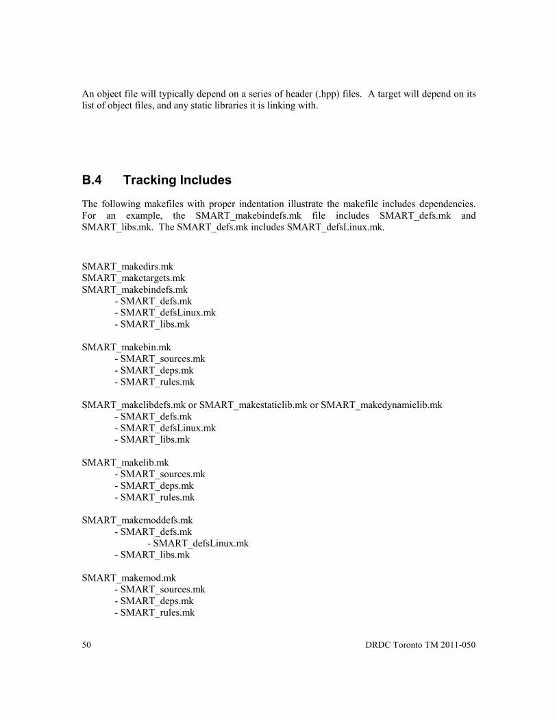
50 DRDC Toronto TM 2011-050
An object file will typically depend on a series of header (.hpp) files. A target will depend on its list of object files, and any static libraries it is linking with.
B.4 Tracking Includes
The following makefiles with proper indentation illustrate the makefile includes dependencies. For an example, the SMART_makebindefs.mk file includes SMART_defs.mk and SMART_libs.mk. The SMART_defs.mk includes SMART_defsLinux.mk.
SMART_makedirs.mk SMART_maketargets.mk SMART_makebindefs.mk - SMART_defs.mk - SMART_defsLinux.mk - SMART_libs.mk SMART_makebin.mk - SMART_sources.mk - SMART_deps.mk - SMART_rules.mk SMART_makelibdefs.mk or SMART_makestaticlib.mk or SMART_makedynamiclib.mk - SMART_defs.mk - SMART_defsLinux.mk - SMART_libs.mk SMART_makelib.mk - SMART_sources.mk - SMART_deps.mk - SMART_rules.mk SMART_makemoddefs.mk - SMART_defs.mk - SMART_defsLinux.mk - SMART_libs.mk SMART_makemod.mk - SMART_sources.mk - SMART_deps.mk - SMART_rules.mk

DRDC Toronto TM 2011-050 51
B.5 Example Makefiles
In general, several variables must be defined, and then the appropriate .mk files included. The exact variables and .mk files depends on the nature of the target being compiled (dir, lib, mod, bin).
----------------- An example makefile for building a binary is included below: >>>>>>>>>>>>>>>>>>>>>>>>>>>>>>>>>>>>>>>>>>>>>>>>>>>>>>>>>>> >>>>>>>>>>>>>>>>>>>>>>>>>>>>>>>>>>>>>>>>>>>>>>>>>>>>>>>>>>> >>>>>>>>>>>>>>>>>>>>>>>>>>>>>>>>>>>>>>>>>>>>>>>>>>>>>>>>>>> # # Name of stub binary # TARGET = $(RHS_BIN_DIR)/dummy_main # # Common variables, rules, and libs used by the target # include $(RHS_INCLUDE_DIR)/RHS_makebindefs.mk # # Define the objects, modules, and libraries used by the binary # OBJS = $(OBJS_DIR)/dummy_main.o STATIC_LIBS = $(SMART_LIBS) \ $(SMART_THREAD_LIBS) \ -lMyOtherStaticLib DYNAMIC_LIBS = -lOneOfMyDynamicLibs MODS = $(COMMON_MOD) \ $(ENTITYDB_MOD) \ $(SOLO_SESSION_MANAGER_MOD) \ $(CONTROL_MOD) \ $(DUMMY_FEDERATE_MOD) \ $(DUMMY_MODEL_MOD) \ $(DUMMY_SCENARIO_MODEL_MOD) \ $(DUMMY_SOURCE_MOD) \ $(DUMMY_CLIENT_MOD) \ $(DUMMY_VIEW_MOD) \ $(DUMMY_PROFILE_MOD) \ $(DUMMY_COMMON_ENGINE_MOD) \ $(DUMMY_LOCAL_ENGINE_MOD) \

52 DRDC Toronto TM 2011-050
$(DUMMY_SCENARIO_COMMON_ENGINE_MOD) \ $(DUMMY_SCENARIO_LOCAL_ENGINE_MOD) # # Include the specific rules for making a binary target # include $(RHS_INCLUDE_DIR)/RHS_makebin.mk <<<<<<<<<<<<<<<<<<<<<<<<<<<<<<<<<<<<<<<<<<<<<<<<<< <<<<<<<<<<<<<<<<<<<<<<<<<<<<<<<<<<<<<<<<<<<<<<<<<< <<<<<<<<<<<<<<<<<<<<<<<<<<<<<<<<<<<<<<<<<<<<<<<<<< ---------- An example makefile for a building a mod is included below: >>>>>>>>>>>>>>>>>>>>>>>>>>>>>>>>>>>>>>>>>>>>>>>>>>>>>>>>>>> >>>>>>>>>>>>>>>>>>>>>>>>>>>>>>>>>>>>>>>>>>>>>>>>>>>>>>>>>>> >>>>>>>>>>>>>>>>>>>>>>>>>>>>>>>>>>>>>>>>>>>>>>>>>>>>>>>>>>> # # Name of mod - this variable isn't used # TARGET = my_mod # # Common variables, rules, and libs used by the target # include $(RHS_INCLUDE_DIR)/RHS_makemoddefs.mk # # The list of object files for this mod... # OBJS = $(OBJS_DIR)/Foo.o \ $(OBJS_DIR)/SuperDuper.o \ $(OBJS_DIR)/Bopper.o # # Include the specific rules for making a module # include $(RHS_INCLUDE_DIR)/RHS_makemod.mk <<<<<<<<<<<<<<<<<<<<<<<<<<<<<<<<<<<<<<<<<<<<<<<<<< <<<<<<<<<<<<<<<<<<<<<<<<<<<<<<<<<<<<<<<<<<<<<<<<<< <<<<<<<<<<<<<<<<<<<<<<<<<<<<<<<<<<<<<<<<<<<<<<<<<< ------------- An example makefile for a building a mod is included below: >>>>>>>>>>>>>>>>>>>>>>>>>>>>>>>>>>>>>>>>>>>>>>>>>>>>>>>>>>>

DRDC Toronto TM 2011-050 53
>>>>>>>>>>>>>>>>>>>>>>>>>>>>>>>>>>>>>>>>>>>>>>>>>>>>>>>>>>> >>>>>>>>>>>>>>>>>>>>>>>>>>>>>>>>>>>>>>>>>>>>>>>>>>>>>>>>>>> # # Name of library # TARGET = $(SMART_LIB_DIR)/libSMARTUtils.a # # Common variables, rules, and libs used by the target # include $(SMART_INCLUDE_DIR)/SMART_makelibdefs.mk # # The list of object files for this library... # OBJS = $(OBJS_DIR)/Coord.o \ $(OBJS_DIR)/Vector.o \ $(OBJS_DIR)/Math.o \ $(OBJS_DIR)/Semaphore.o # # Include the specific rules for making a static library # include $(SMART_INCLUDE_DIR)/SMART_makestaticlib.mk <<<<<<<<<<<<<<<<<<<<<<<<<<<<<<<<<<<<<<<<<<<<<<<<<< <<<<<<<<<<<<<<<<<<<<<<<<<<<<<<<<<<<<<<<<<<<<<<<<<< <<<<<<<<<<<<<<<<<<<<<<<<<<<<<<<<<<<<<<<<<<<<<<<<<<
B.6 List of SMART Make Files
B.6.1 SMART_defs.mk #!gmake -j ############################################# # # Common Makefile include for all SMART makefiles # # Copyright (c) 1999, 2000 # # Krajcarski, Robert
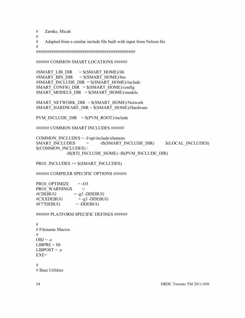
54 DRDC Toronto TM 2011-050
# Zarnke, Micah # # Adapted from a similar include file built with input from Nelson Ho # ############################################# ###### COMMON SMART LOCATIONS ###### #SMART_LIB_DIR = $(SMART_HOME)/lib #SMART_BIN_DIR = $(SMART_HOME)/bin #SMART_INCLUDE_DIR = $(SMART_HOME)/include SMART_CONFIG_DIR = $(SMART_HOME)/config SMART_MODELS_DIR = $(SMART_HOME)/models SMART_NETWORK_DIR = $(SMART_HOME)/Network SMART_HARDWARE_DIR = $(SMART_HOME)/Hardware PVM_INCLUDE_DIR = $(PVM_ROOT)/include ###### COMMON SMART INCLUDES ###### COMMON_INCLUDES = -I/opt/include/elumens SMART_INCLUDES = -I$(SMART_INCLUDE_DIR) $(LOCAL_INCLUDES) $(COMMON_INCLUDES) \ -I$(RTI_INCLUDE_HOME) -I$(PVM_INCLUDE_DIR) PROJ_INCLUDES += $(SMART_INCLUDES) ###### COMPILER SPECIFIC OPTIONS ###### PROJ_OPTIMIZE = -O3 PROJ_WARNINGS = #CDEBUG = -g3 -DDEBUG #CXXDEBUG = -g3 -DDEBUG #F77DEBUG = -DDEBUG ###### PLATFORM SPECIFIC DEFINES ###### # # Filename Macros # OBJ = .o LIBPRE = lib LIBPOST = .a EXE= # # Base Utilities

DRDC Toronto TM 2011-050 55
# CC = cc CXX = CC F77 = f77 LD = ld MAKE_STATIC_LIB = $(CXX) -ar -o MAKE_DYNAMIC_LIB = $(CXX) -shared # This was changed after a gcc compiler upgrade from 2.95 to 3.0.4 on the # SGI machines. With the change in versions, the location of the hash_map # include changed messing up the generation of dependencies. It is better # if we can use gcc -MM to generate dependencies because it excludes system # header files, but becase gcc now has <hash_map> in a different place than # CC, we will have to use the same compiler to generate the dependancies that # we use for actual compiling (for IRIX and IRIX64 this means CC). #MAKEDEP = gcc -MM MAKEDEP = $(CXX) -M MAKEDEP_F77 = f77 -M MAKEDIR = mkdir RANLIB = ar -s AS = as FLUID = fluid ARCH = $(SMART_ARCH) # # Shell Commands # RM = rm -f CP = cp -f MV = mv -f MKDIR = mkdir -p include $(SMART_INCLUDE_DIR)/SMART_defs$(ARCH).mk # # Compiler flags FLAGS +=$(PROJ_INCLUDES) $(PROJ_WARNINGS) $(PROJ_OPTIMIZE) CFLAGS +=$(FLAGS) ${CDEBUG} CXXFLAGS +=$(FLAGS) ${CXXDEBUG} F77FLAGS +=$(FLAGS) ${F77DEBUG} MAKEDEP_FLAGS +=$(FLAGS) MAKELIB_FLAGS += LDFLAGS = ARFLAGS = ASFLAGS =

56 DRDC Toronto TM 2011-050
B.6.2 SMART_defsLinux.mk
############################################# # # Common Makefile include dealing with Linux specific defines # # Copyright (c) 1999, 2000 # # Krajcarski, Robert # Zarnke, Micah # # Adapted from a similar include file built with input from Nelson Ho # ############################################# # Base Utilities # #ALLEN AJIT GEORGE CC = gcc-4.3 CXX = g++-4.3 F77 = g77 -g2 -finit-local-zero -fno-automatic MAKE_STATIC_LIB = ar -r MAKEDEP = $(CXX) -MM MAKEDIR = mkdir SHELL = /bin/bash -c FORTRAN_LIBS = -lg2c FLTK_LIBS = -L/usr/local/lib -lfltk_v3 $(X11_LIBS) X11_LIB_HOME = -L/usr/X11R6/lib MAKELIB_FLAGS = #CXXFLAGS += -g2 -DDEBUG -DPERF_VER_2_4 -ftemplate-depth-99 -Wall \ # CXXFLAGS += -DPERF_VER_2_4 -ftemplate-depth-99 -Wall \ -DSMART_LE_BYTE_ORDER -DREENTRANT -DRTI_USES_STD_FSTREAM \ -DPOSIX_PTHREAD_SEMANTICS PROJ_WARNINGS += -Wno-ctor-dtor-privacy
B.6.3 SMART_deps.mk #! gmake

DRDC Toronto TM 2011-050 57
################################# # # SMART Makefile # # This will create a single .d file for every .o file in OBJS. The .d # file is a list of all includes for the given object and is included as # a list of dependandcies for rebuilding the .o. # # Required: OBJS - list of object files for which the dependancies are built # OBJS_DIR - location of object files # DEPS_DIR - location of dependancy files # # Output: DEPS - list of .d files # LIB_DEPS - list of project library dependancies # # Copyright (c) 1999, 2000 # # Krajcarski, Robert # Zarnke, Micah # ################################## # # for now assume anything in LIBS is static (this is to support stubs and # things created before we cared about static vs dynamic) # STATIC_LIBS += $(LIBS) # # first build the lib dependancies by removing all nonlibs from the list # LIB_DEPS += $(filter -lSMART%, $(filter-out -L%, $(STATIC_LIBS))) ################# Dependacy stuff #################### # # In each source directory there is a ./deps directory containing a single # .d file for every .o file. Each .d file contains a list of dependancies # for both the .d and corresponding .o. The compiler will check those # dependancies to determine whether or not to rebuild the .d or .o. # The .d is built using the implicit rules defined below. # # # If DEPS_DIR wasn't set, assign a default # ifeq (,$(DEPS_DIR))

58 DRDC Toronto TM 2011-050
DEPS_DIR = deps/$(ARCH) endif # # build the list of dependancy files... one and only one for each object file # SINGLE_OBJS = $(notdir $(OBJS)) DEPS = $(addprefix $(DEPS_DIR)/,$(SINGLE_OBJS:.o=.d)) # # Include the dependancy files (sinclude ignores failures) but only if not # building 'clean'. sinclude will attempt to make any target files it # can't find, and if we're cleaning everything out, we don't want to waste # time first building things up. # ifeq (,$(findstring clean,$(MAKECMDGOALS))) ifeq (,$(findstring cleanall,$(MAKECMDGOALS))) sinclude $(DEPS) endif endif ################ Dependancy Rules ##################### # # The .d file is first built by using the -M compiler option. This # does a search through the .cpp file recording all of the non-system # include files. The search is recursive, so it contains names of files # included by files included by the .cpp. # # The second part of the command (sed) takes the file list of the form: # foo.o: foo.cpp foo.hpp foobase.hpp global.hpp # # and replaces it with a file of the form: # foo.o deps/foo.d: foo.cpp foo.hpp foobase.hpp global.hpp # # This ensures that the both the .o and the .d file are rebuilt if one # of the dependancies changes (just in case you add or delete an #include). # # These DR vars are a clever hack to allow \s in the sed command DR_DEPS_DIR =$(subst /,\/,$(DEPS_DIR)) DR_OBJS_DIR =$(subst /,\/,$(OBJS_DIR)) # # create a macro command for creating the dependancy files #

DRDC Toronto TM 2011-050 59
define MAKE_DEPS @$(SHELL) 'if [ ! -d $(DEPS_DIR) ]; then \ echo ; \ echo Creating deps directory $(DEPS_DIR) ; \ $(MKDIR) $(DEPS_DIR) ; \ fi' @echo; \ echo Making dependancies file: $@ @$(MAKEDEP) $(MAKEDEP_FLAGS) $< | \ sed 's/\($*\)\.o[ :]*/$(DR_OBJS_DIR)\/\1.o $(DR_DEPS_DIR)\/$(@F) : /g' > $@; endef # # Rules for making the dependancies # $(DEPS_DIR)/%.d: %.cpp $(MAKE_DEPS) $(DEPS_DIR)/%.d: %.cxx $(MAKE_DEPS) $(DEPS_DIR)/%.d: %.C $(MAKE_DEPS) $(DEPS_DIR)/%.d: %.c $(MAKE_DEPS) $(DEPS_DIR)/%.d: %.F $(MAKE_DEPS)
B.6.4 SMART_libs.mk #!gmake ################################# # # SMART Makefile # # Defines variables for the standard system libraries and all smart # libraries provided by smart. # # Copyright (c) 1999, 2000 #
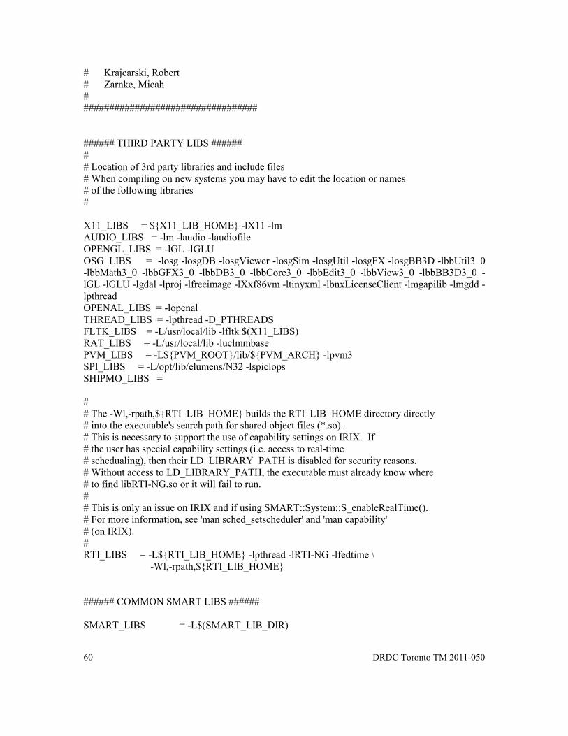
60 DRDC Toronto TM 2011-050
# Krajcarski, Robert # Zarnke, Micah # ################################## ###### THIRD PARTY LIBS ###### # # Location of 3rd party libraries and include files # When compiling on new systems you may have to edit the location or names # of the following libraries # X11_LIBS = ${X11_LIB_HOME} -lX11 -lm AUDIO_LIBS = -lm -laudio -laudiofile OPENGL_LIBS = -lGL -lGLU OSG_LIBS = -losg -losgDB -losgViewer -losgSim -losgUtil -losgFX -losgBB3D -lbbUtil3_0 -lbbMath3_0 -lbbGFX3_0 -lbbDB3_0 -lbbCore3_0 -lbbEdit3_0 -lbbView3_0 -lbbBB3D3_0 -lGL -lGLU -lgdal -lproj -lfreeimage -lXxf86vm -ltinyxml -lbnxLicenseClient -lmgapilib -lmgdd -lpthread OPENAL_LIBS = -lopenal THREAD_LIBS = -lpthread -D_PTHREADS FLTK_LIBS = -L/usr/local/lib -lfltk $(X11_LIBS) RAT_LIBS = -L/usr/local/lib -luclmmbase PVM_LIBS = -L${PVM_ROOT}/lib/${PVM_ARCH} -lpvm3 SPI_LIBS = -L/opt/lib/elumens/N32 -lspiclops SHIPMO_LIBS = # # The -Wl,-rpath,${RTI_LIB_HOME} builds the RTI_LIB_HOME directory directly # into the executable's search path for shared object files (*.so). # This is necessary to support the use of capability settings on IRIX. If # the user has special capability settings (i.e. access to real-time # schedualing), then their LD_LIBRARY_PATH is disabled for security reasons. # Without access to LD_LIBRARY_PATH, the executable must already know where # to find libRTI-NG.so or it will fail to run. # # This is only an issue on IRIX and if using SMART::System::S_enableRealTime(). # For more information, see 'man sched_setscheduler' and 'man capability' # (on IRIX). # RTI_LIBS = -L${RTI_LIB_HOME} -lpthread -lRTI-NG -lfedtime \ -Wl,-rpath,${RTI_LIB_HOME} ###### COMMON SMART LIBS ###### SMART_LIBS = -L$(SMART_LIB_DIR)

DRDC Toronto TM 2011-050 61
SMART_UTILS_LIBS = -lSMARTUtils -lm SMART_DEBUG_LIBS = -lSMARTDebug SMART_FILEIO_LIBS = -lSMARTFileIO SMART_THREAD_LIBS = -lSMARTThread $(THREAD_LIBS) SMART_CEREALBOX_LIBS = -lSMARTCerealBox SMART_TRACKER_LIBS = -lSMARTTracker SMART_PLATFORM_LIBS = -lSMARTPlatform SMART_AUDIO_LIBS = -lSMARTAudio SMART_SOCKET_LIBS = -lSMARTSocket SMART_DATATREE_LIBS = -lSMARTDataTree SMART_FLTK_LIBS = -lSMARTFltk $(FLTK_LIBS) SMART_SHIP_DYNAMICS_LIBS = -lSMARTShipDynamics $(FORTRAN_LIBS) SMART_GENHEL_LIBS = -lSMARTGenHel SMART_SEA_DYNAMICS_LIBS = -lSMARTSeaDynamics SMART_OSG_LIBS = -lSMARTOSGDriver $(OSG_LIBS) SMART_HDL_READER_LIBS = -lHDLReader SMART_RAT_LIBS = -lSMARTRAT $(RAT_LIBS) SMART_AUDIO_COMM_LIBS = -lSMARTAudioComm SMART_RECORD_LIBS = -lSMARTRecord SMART_SEAKING_LIBS = -lSMARTSeaKing SMART_MATRIXX_LIBS = -lSMARTMatrixX SMART_JETRANGER_LIBS = -lSMARTJetRanger SMART_EH101_LIBS = -lSMARTEH101 SMART_PVM_LIBS = -lSMARTPVM $(PVM_LIBS) SMART_SERIAL_PORT_LIBS = -lSMARTSerialPort SMART_IPME_LIBS = -lSMARTIPME SMART_ASTI_LIBS = -lSMARTASTI SMART_SHIPMO_LIBS = -lSMARTShipMo $(SHIPMO_LIBS) SMART_BASE_LIBS = $(SMART_LIBS) \ $(SMART_FILEIO_LIBS) \ $(SMART_THREAD_LIBS) \ $(SMART_DEBUG_LIBS) \ $(SMART_UTILS_LIBS) \ $(X11_LIBS) ifdef REMOVE_NIM SMART_NIM_LIBS = else SMART_NIM_LIBS = -lSMARTNIM $(RTI_LIBS) endif # # The VPATH is where make searches for dependancy files (i.e. -lSMARTmylib) # Note when it finds a library as a dependancy, it knows to expand it to # it's full name (i.e. libSMARTmylib.a) # VPATH += $(SMART_LIB_DIR)

62 DRDC Toronto TM 2011-050
B.6.5 SMART_rules.mk #! gmake -j ################################# # # SMART Makefile # # Required: OBJS_DIR - location of object files # DEPS_DIR - location of dependancy files # # Copyright (c) 1999, 2000 # # Krajcarski, Robert # Zarnke, Micah # ################################## ###### COMMON RULES AND TARGETS ###### # # Rules # .SUFFIXES: .o .cpp .c .d .F .fl .C .cxx #### protect the targets that should always be run without question .PHONY : clean cleanall all # # The name of the ii_files for the specified OBJS # II_FILES = $(addprefix $(OBJS_DIR)/ii_files/,$(notdir $(OBJS:.o=.ii))) # # Macro for the command to create the directory for object files # define MAKE_OBJS_DIR @$(SHELL) 'if [ ! -d $(OBJS_DIR) ]; then \ echo ; \ echo Creating object directory $(OBJS_DIR) ; \ $(MKDIR) $(OBJS_DIR) ; \ fi' @echo; endef

DRDC Toronto TM 2011-050 63
# # Standard rules for building .o files. The objs directory must be # created if it doesn't already exist. # $(OBJS_DIR)/%.o: %.c $(MAKE_OBJS_DIR) $(CC) $(CFLAGS) -o $@ -c $*.c $(OBJS_DIR)/%.o: %.cpp $(MAKE_OBJS_DIR) $(CXX) $(CXXFLAGS) -o $@ -c $*.cpp $(OBJS_DIR)/%.o: %.cxx $(MAKE_OBJS_DIR) $(CXX) $(CXXFLAGS) -o $@ -c $*.cxx $(OBJS_DIR)/%.o: %.C $(MAKE_OBJS_DIR) $(CXX) $(CXXFLAGS) -o $@ -c $*.C $(OBJS_DIR)/%.o: %.F $(MAKE_OBJS_DIR) $(F77) $(F77FLAGS) -o $@ -c $*.F # # Clean .o files, .d files, and all targets # clean cleanall: -$(RM) $(OBJS) -$(RM) $(II_FILES) -$(RM) $(DEPS) -$(RM) $(TARGET) -$(RM) *~ stub
B.6.6 SMART_sources.mk #! gmake -j ################################# # # SMART Makefile # # Required: # # Copyright (c) 1999, 2000, 2001

64 DRDC Toronto TM 2011-050
# # Krajcarski, Robert # Zarnke, Micah # ################################## ###### COMMON RULES FOR MAKING SOURCE FILES ###### # # Rules for building .hpp and .cpp files # %.hpp %.cpp: %.fl @echo; @echo Building gui source and header files $(FLUID) -o .cpp -h .hpp -c $^ %.hpp: @echo; \ echo Ignoring missing file $@
B.6.7 SMART_makedirs.mk
#! gmake ################################# # # SMART Makefile # # Required: DIRS - List of subdirectories to be built # # Copyright (c) 1999, 2000 # # Krajcarski, Robert # Zarnke, Micah # ################################## # # Loop through the specified DIRS calling make in each with the same # arguemnets whith which this makefile level was called. # # RK Changed the 'cd' commands to go back to the original working directory

DRDC Toronto TM 2011-050 65
# so we can properly handle deep children. Also added test to see if directory # exists CURRENT_DIR = $(PWD) # make sure default is the first one here default all clean cleanall: @for DIR in $(DIRS); do \ if [ -d $$DIR ]; then \ echo ; echo "/------------- $$DIR --------------/" ; echo ; \ cd $$DIR; \ $(MAKE) $@; \ cd $(CURRENT_DIR); \ fi \ done @echo ; echo
B.6.8 SMART_maketargets.mk #!gmake # note the lack of "-j" above... this is so that things are done # one at a time ################################# # # SMART Makefile # # This will loop through the targets and stubs calling a separate makefile # for each. The name of each makefile is taken from the name of the # target or stub and appanded with .mk. Each makefile is called with the # same arguments with which this level of Makefile was called. # # Required: TARGETS - list of normal targets to build by default # STUBS - list of stubs to build with the 'stubs' target # Copyright (c) 1999, 2000 # # Krajcarski, Robert # Zarnke, Micah # ################################## # # Prefix the list with the word clean and cleanall... this will later be # used to identify which arguement to give to the makefiles

66 DRDC Toronto TM 2011-050
# CLEAN = $(addprefix clean, $(TARGETS)) CLEANALL = $(addprefix cleanall, $(TARGETS)) $(addprefix cleanall, $(STUBS)) # # We now want to append in all the platform specific targets # TARGETS := $(TARGETS) $($(SMART_ARCH)_TARGETS) STUBS := $(STUBS) $($(SMART_ARCH)_STUBS) # # Standard make arguements should apply to all targets and stubs # default : $(TARGETS) all : $(TARGETS) $(STUBS) stubs: $(STUBS) clean: $(CLEAN) cleanall: $(CLEANALL) $(TARGETS) $(STUBS): @echo; \ echo " /-- $@ --/"; \ echo; @$(MAKE) -f [email protected] $(CLEAN): @echo; \ echo " /-- $(subst clean,,$@) clean --/"; \ echo; @$(MAKE) -f $(subst clean,,$@).mk clean ; $(CLEANALL): @echo; \ echo " /-- $(subst cleanall,,$@) cleanall --/"; \ echo; @$(MAKE) -f $(subst cleanall,,$@).mk cleanall ;
B.6.9 SMART_makebin.mk #!gmake -j ################################# # # SMART Makefile # # Required: TARGET - the target binary name

DRDC Toronto TM 2011-050 67
# OBJS - list of objects in the binary # SHARED_LIBS - list of static (.a) libraries used by the binary # DYNAMIC_LIBS - list of dynamic (.so) libraries used by the binary # MODS - list of modules used by the binary # # Copyright (c) 1999, 2000 # # Krajcarski, Robert # Zarnke, Micah # ################################## # # Include all common dependancies and rules for the target # include $(SMART_INCLUDE_DIR)/SMART_sources.mk include $(SMART_INCLUDE_DIR)/SMART_deps.mk include $(SMART_INCLUDE_DIR)/SMART_rules.mk # # sort and prune the list of objects and mods to remove duplicates # PRUNED_OBJS = $(sort $(OBJS)) PRUNED_MODS = $(sort $(MODS)) # # include both static and shared libs # ALL_LIBS = $(DYNAMIC_LIBS) $(STATIC_LIBS) # # The actual rule for making binaries # $(TARGET): $(DEPS) $(PRUNED_OBJS) $(PRUNED_MODS) $(LIB_DEPS) @$(SHELL) 'if [ ! -d $(@D) ]; then \ echo ; \ echo Creating object directory $(@D) ; \ $(MKDIR) $(@D) ; \ fi' @echo; $(CXX) $(CXXFLAGS) $(PRUNED_OBJS) $(PRUNED_MODS) $(ALL_LIBS) -o $@
B.6.10 SMART_makebindefs.mk #################################

68 DRDC Toronto TM 2011-050
# # SMART Makefile # # Required: TARGET - the target binary name # # Copyright (c) 1999, 2000 # # Krajcarski, Robert # Zarnke, Micah # ################################## # # This is the default rule (first rule encountered) # default all: $(TARGET) # # Locations used by included makefiles # OBJS_DIR = objs/$(ARCH) DEPS_DIR = deps/$(ARCH) MODS_DIR = # # Common variables, rules, libraries, and dependancies # include $(SMART_INCLUDE_DIR)/SMART_defs.mk include $(SMART_INCLUDE_DIR)/SMART_libs.mk
B.6.11 SMART_makelib.mk #!gmake -j ################################# # # SMART Makefile # # OBSOLETE!!!!! - please use SMART_makestaticlib or SMART_makedynamiclib # # # Required: TARGET - the full target library name # OBJS - list of objects in the library

DRDC Toronto TM 2011-050 69
# MODS - list of modules used by the library # # Copyright (c) 1999, 2000 # # Krajcarski, Robert # Zarnke, Micah # ################################## include $(SMART_INCLUDE_DIR)/SMART_makestaticlib.mk # # Include all dependancies and rules for the target # #include $(SMART_INCLUDE_DIR)/SMART_sources.mk #include $(SMART_INCLUDE_DIR)/SMART_deps.mk #include $(SMART_INCLUDE_DIR)/SMART_rules.mk # # first sort and prune the list of objects to remove duplicates # #PRUNED_OBJS = $(sort $(OBJS) $(MODS)) # # Rule for making the library # #$(TARGET): $(DEPS) $(PRUNED_OBJS) # @echo ; # $(MAKE_STATIC_LIB) $@ $(MAKELIB_FLAGS) $(PRUNED_OBJS)
B.6.12 SMART_makelibdefs.mk ################################# # # SMART Makefile # # Required: TARGET - the target binary name # # Copyright (c) 1999, 2000 # # Krajcarski, Robert # Zarnke, Micah #

70 DRDC Toronto TM 2011-050
################################## # # This is the default rule (first rule encountered) # default all: $(TARGET) # # Locations used by included makefiles # OBJS_DIR = objs/$(ARCH) DEPS_DIR = deps/$(ARCH) MODS_DIR = # # Common variables, rules, libraries, and dependancies # include $(SMART_INCLUDE_DIR)/SMART_defs.mk include $(SMART_INCLUDE_DIR)/SMART_libs.mk
B.6.13 SMART_makestaticlib.mk #!gmake -j ################################# # # SMART Makefile # # Required: TARGET - the full target library name # OBJS - list of objects in the library # MODS - list of modules used by the library # # Copyright (c) 1999, 2000 # # Krajcarski, Robert # Zarnke, Micah # ################################## # # Include all dependancies and rules for the target # include $(SMART_INCLUDE_DIR)/SMART_sources.mk include $(SMART_INCLUDE_DIR)/SMART_deps.mk include $(SMART_INCLUDE_DIR)/SMART_rules.mk

DRDC Toronto TM 2011-050 71
# # first sort and prune the list of objects to remove duplicates # PRUNED_OBJS = $(sort $(OBJS) $(MODS)) # # Rule for making the library # $(TARGET): $(DEPS) $(PRUNED_OBJS) @$(SHELL) 'if [ ! -d $(@D) ]; then \ echo ; \ echo Creating object directory $(@D) ; \ $(MKDIR) $(@D) ; \ fi' @echo ; $(MAKE_STATIC_LIB) $@ $(MAKELIB_FLAGS) $(PRUNED_OBJS)
B.6.14 SMART_makedynamiclib.mk #!gmake -j ################################# # # SMART Makefile # # Required: TARGET - the full target library name # OBJS - list of objects in the library # MODS - list of modules used by the library # # Copyright (c) 1999, 2000 # # Krajcarski, Robert # Zarnke, Micah # ################################## # # Include all dependancies and rules for the target # include $(SMART_INCLUDE_DIR)/SMART_sources.mk include $(SMART_INCLUDE_DIR)/SMART_deps.mk include $(SMART_INCLUDE_DIR)/SMART_rules.mk #

72 DRDC Toronto TM 2011-050
# first sort and prune the list of objects to remove duplicates # PRUNED_OBJS = $(sort $(OBJS) $(MODS)) # # Rule for making the library # $(TARGET): $(DEPS) $(PRUNED_OBJS) @$(SHELL) 'if [ ! -d $(@D) ]; then \ echo ; \ echo Creating object directory $(@D) ; \ $(MKDIR) $(@D) ; \ fi' @echo ; $(MAKE_DYNAMIC_LIB) $(MAKELIB_FLAGS) $(PRUNED_OBJS) -o $@
B.6.15 SMART_makemod.mk #!gmake -j ################################# # # SMART Makefile # # Required: OBJS - list of objects in the binary # # Copyright (c) 1999, 2000 # # Krajcarski, Robert # Zarnke, Micah # ################################## # # Include all common dependancies and rules for the target # include $(SMART_INCLUDE_DIR)/SMART_sources.mk include $(SMART_INCLUDE_DIR)/SMART_deps.mk include $(SMART_INCLUDE_DIR)/SMART_rules.mk # # sort and prune the list of objects to remove duplicates # PRUNED_OBJS = $(sort $(OBJS))

DRDC Toronto TM 2011-050 73
# # Rule for building the object files that make up the module # $(TARGET): $(DEPS) $(PRUNED_OBJS)
B.6.16 SMART_makemoddefs.mk #!gmake ################################# # # Required: TARGET - full name of target to build # # Copyright (c) 1999, 2000 # # Krajcarski, Robert # Zarnke, Micah # ################################## # # This is the default rule (first rule encountered) # default all: $(TARGET) # # Locations used by the included makefiles # OBJS_DIR = objs/$(ARCH) DEPS_DIR = deps/$(ARCH) MODS_DIR = objs/$(ARCH) # # Common variables, rules, modules, libraries, and dependancies # include $(SMART_INCLUDE_DIR)/SMART_defs.mk include $(SMART_INCLUDE_DIR)/SMART_libs.mk

74 DRDC Toronto TM 2011-050
Annex C MatrixX Notes – Sea King Simulator
C.1 MatrixX Notes – Sea King Simulator
The information listed here is by no means a comprehensive or exhaustive list of MatrixX functions. The notes here are designed to guide the user through some very basic functions of MatrixX and simple model manipulation.
For any information on operation or user interface, please consult the MatrixX online documentation. However, it is not recommended that an individual unfamiliar with the program manipulate modules for the Sea King simulator. The following documentation should be referenced for future support of MatrixX – Sea King Simulator software:
MatrixX Online Documentation CD
MatrixX CD-ROM Installation Procedure
MatrixX Getting Started (Windows) Manual
MatrixX System Administrator's Guide (Windows)
MatrixX Autocode Application Notes.
C.2 MatrixX Getting Started
MatrixX consists of a CD-ROM disk for installation and another for online documentation. Installation details can be found with the software. DRDC Toronto has run MatrixX on a Windows NT SGI workstation. To start the program, click the “Xmath” icon under the Start menu.
MatrixX has three working environments for model manipulation. Each environment is specially structured to allow for the type of model manipulation desired. The first environment that the user will encounter is called “Xmath”. This environment is a command line type of user interface. It allows the user to probe variable values and complete mathematical calculations. All simulation functions can be accessed in this environment and run in a manual mode where the user can specify options at the command line.

DRDC Toronto TM 2011-050 75
C.3 Change in a Variable
Under the “Xmath” environment, simulation variables can also be accessed. Under the current system, all helicopter physical, integrator, aerodynamic, engine, and atmospheric data are contained here. As this is a critical database, the following steps may be taken to modify these variables.
1. Drop down the “window” heading at the top of the “Xmath” environment and choose “variables”.
2. All variables used in the current system will be displayed within this window, which is called the “variable manager”. Variables can be grouped in partitions that allow for separate identification in modules. To look at variables located in other partitions, drop and choose a partition at the bottom of the “variable manager” window.
3. To modify a variable one may choose to use the buttons within the variable manager but caution must be used here. Only scalar variables can be modified under the variable manager.
4. To modify any other variable, type the variable name and its value in the command window of MatrixX. For syntax, see online Xmath documentation.
Example: partition1.variable1=[1,0;0,1];
This will produce a variable called “variable1” within the partition called “partition1” that is the identity matrix.
C.4 Systembuild
The other environments contained within MatrixX are called the “Systembuild Catalog Browser” and the “Systembuild Simulation” window.
To get to the catalogue browser, the user must click on the heading “window” in the Xmath environment. Once there, the user must select the “Systembuild” option on the pull down menu. The Systembuild catalogue browser window will now appear. This environment is very similar to the standard Microsoft Windows explorer and it allows the user to manipulate all of the blocks simultaneously. It also gives all of the block specific information in a concise display for the entire simulation. Block type, ID, sample period, inputs, outputs and name are all displayed in this environment. The user can also manipulate any of these properties within the catalogue browser. The browser also holds the simulation and autocode functions within a windows type environment. Here, instead of using the command line within Xmath to perform functions, they are presented in button format and automated.

76 DRDC Toronto TM 2011-050
The Systembuild environment can be accessed by double-clicking on any module contained within the Systembuild catalogue browser. A new window will appear that contains the module that the user has selected. This environment is where the simulation and all of the associated blocks and their connections are contained. It gives a graphical overview of the system at any level of the simulation. To view a higher level, the user can go to the catalogue browser and double-click on a higher-level module or use the up folder icon in the Systembuild simulator window.
C.5 Save a Change
There are many ways to manipulate data and modules in MatrixX. The simplest way to save all changes for a particular session is to go to the Xmath environment and to the “file” heading and click on “save” from the pull down menu. This saves the entire model in a file of type .XMD. All data and model changes will be represented here. For detailed saving procedures involving only Xmath data, partial models, etc., consult the online documentation for MatrixX.
C.6 AutoCode
To AutoCode a model, the user must first highlight that model in the “catalog browser” window. Once highlighted the user may choose “tools” from the pull down menu and select “AutoCode”. Then the user must select a file name for the .c file.
For all the AutoCodes performed by DRDC Toronto, some advanced properties for AutoCode were used. The template file SeaKing.tpl was used. Under the “Optimization” heading “Merge INIT Sections”, “No UY Structures”, and Vectorization of “Labels” were used. A loop threshold of 2 and array threshold of 2 were also selected for the vectorization option. Once all these parameters have been selected, the user may click OK to start the AutoCode process. A *.c and *.h file should be created according to the name that the user has selected.
C.7 Transfer AutoCode to the Sea King Development Directory
To transfer the code to the Sea King Simulator development directory you are using, place the code in the smart/src/Dynamics/Helo/MatrixX directory. In the current scheme the code must be called SeaKingAutoCode.h and SeaKingAutoCode.c to work. Once the code has been copied

DRDC Toronto TM 2011-050 77
over correctly, the directory can be built by typing, “make”. This step will compile the source code and create a library libSMARTMatrixX.a.
C.8 Structure of the MatrixX Dynamics Code Model
The generated AutoCode defines many global variables and several global functions that do all the calculations for the dynamics model. One super function, subsys_1(), is responsible for calling all the functions and handling all the variables in the correct manner. This function takes in an input structure that has all the positions of the flight controls as well as several flags that tell the state of the helicopter and an output structure that will contain the updated instrument readings.
A wrapper/driver program is used to call the subsys_1() function with the appropriate input and to relay the resulting helicopter behaviour to the simulator. This is all contained in the SeaKingDriver class.
C.9 Troubleshooting Process
1. If the AutoCode did not generate properly with no errors then the C code will not compile properly.
2. If the MatrixX model is changed even a little bit, the layout of the generated C code will be drastically affected. The driver program is written so as to use a specific/perfect MatrixX model. This perfect C code model is defined by these characteristics:
No dczero structure in the input structure
There is a Sys_Extin structure, and a subsy_1_out structure. If you have a Sys_Extin structure and a Subsys_Extout structure, as well as a subsys_1_in structure, you will need to either change the MatrixX model to eliminate what is causing the multiple structures or change the driver so that the input data is being put to the subsys_1_in structure and that structure is being passed to the subsys_1() function.
3. If the AutoCode still does not compile, then it is required to AutoCode the MatrixX model using the standalone template, c_sim3.tpl, provided by UTIAS. This template will create a C program that will take in a MatrixX input file, generated in MatrixX that contains the inputs to the model over a specific time period and generate an output file that has all the data from the outputs for each cycle during the run. Compile this program, linking in all the sa_*.* files that are needed. If this AutoCode will not compile then there is a problem in the MatrixX AutoCode procedure. This program should also give the same basic behaviour as the MatrixX

78 DRDC Toronto TM 2011-050
model simulated. However, Slightly different results may be produced because of the random number generator used in calculating the wind effects of turbulence.
4. If the standalone program compiles and runs, then look at the driver program and what it is doing. The C code generated by the Sea King template is basically the same code generated by the standalone program except the scheduler and main functions are removed. The driver and the simulator take the place of these.
5. Even if the AutoCode would compile eventually, the helicopter may behave strangely. This is due to the fact that the process is not very stable and any number of problems big or small will cause the helicopter to behave improperly. Unfortunately, only spending a lot time debugging the simulator will help you figure out what is going on. The following tips will help debug the problems:
Startup: the trimming process used to stabilize the helicopter is to be used on for startup during flight. Here the helicopter should be very well behaved, and should stay at the same height, speed and such. Starting on the ground is not supported by UTIAS, so the helicopter is trimmed just above the deck and is then slowly lowered to the deck. This is a troublesome way of doing it but after a lot of time we found a way of making it work. However, any changes to the model or driver may not make starting on the deck as good as it was.
Flight: to debug problems during flight, make sure that all the correct inputs are being sent and that all the correct flags are on. Then look at the forces on the helicopter. The forces come from several different areas, the tail, rotor, landing gear, and haul-down system. If any of these forces behave strangely or are too large then isolate that subsystem and continue backtracking to determine what is causing that force to behave strangely.

DRDC Toronto TM 2011-050 79
Annex D Modifications of Simulator Visual Models
D.1 Introduction
There are two main visual models in the simulator, the CPF and the Sea King helicopter. Both of these three-dimensional objects were modeled using MultiGen Creator, which has the file extension classfification .flt. MultiGen Creator is a modelling tool that produces realistic three-dimensional models for use in real-time applications. One of the reasons why this modelling software package is the most used presently in the industry of real-time modelling is the integrated set of powerful tools it offers for building hierarchical visual databases. The main distinction between this modelling design software package and most others is its ability to create a database to control and maintain objects during real-time simulations. The database design aspect of the models created in Creator inherits theories and concepts from conventional database design methodologies. Using this convention, dynamic visual simulations can be created effectively while still maintaining the characteristic of manipulating data in an optimized manner.
To fully understand how to maintain and upgrade visual models for real-time simulation, a clear understanding of the goals of real-time applications must be discussed. The following is a list of a few of the most fundamental goals of real-time applications.
1. The emphasis is on immersive interaction between active audiences (i.e. Pilot, LSO, Instructor, etc.) and responsive simulation.
2. Real-world dimensions, rules, and constraints are important to the goals of the simulation (e.g., the locations of certain pilot controls, maximum and minimum angle of rotation for those controls).
3. Frames must be fully rendered and displayed at 30 to 60 frames per second. In the Simulator, the target frame rate is set at 60 frames per second.
4. Efficient polygonal models contain only the necessary polygons to achieve the desired effect. The desired effect can entitle showing only correct visuals to corresponding active audiences.
5. Data structures are hierarchically optimised for program traversal and IG state control. Data also contains model controls, real-world constraints, and geometry optimizations.
Using the above rules as guidelines for maintaining and upgrading models for real-time will facilitate the progression of making changes in the simulator visual models for the future.

80 DRDC Toronto TM 2011-050
D.2 Simulator Database Design and Concepts
Most of the upgrading and maintenance of a model created in MultiGen Creator is done in the hierarchical design of the database. The conventional database design of a 3D model in MultiGen Creator integrates the concepts of data tree structures from fundamental computer algorithmic theories. The result of a database created in MultiGen Creator is a directed acyclic graph of nodes. An initial database of a three-dimensional model starts with a root parent node called db. This node simply represents the entire database and any information about the database/model as a whole. In the hierarchical view of MultiGen Creator, double-clicking on the db parent node of a database will trigger a window to pop up with the attributes of that node. For a database node db, attributes include the format origin, revision date, format version, database units, and more.
The Sea King helicopter database hierarchy is shown in Figure D-1. Note that the database (/savdb/models/Seaking/Seaking_MARCH15.flt) is not fully expanded and only shows the major parent nodes that control the most essential parts of the database.

DRDC Toronto TM 2011-050 81
Figure D- 1: Hierarchical View of Sea King Helicopter Database

82 DRDC Toronto TM 2011-050
In the Sea King database view shown in the previous figure, the main parent node of the database is the db node. The child of this node is a node that represents the entire helicopter model. When changes are made to this node, the entire sub-tree inherits the modifications. For instance, when applying a transformation to the helicopter’s position, the helicopter node needs to be selected in order to apply the transformation matrix. This transformation to the helicopter node will be innate in all the children of the node, thereby transforming all geometry by the same transformation matrix.
The child node of the helicopter node is called a degree of freedom node (the white coloured node labelled Heli_DC (DOF)). This is a special node that is created in order to allow real-time graphics-rendering tools, such as OpenGL performer to set the co-ordinates of objects during the simulation. The degree of freedom node is a node that controls the movement of all children objects. Because the transformation of objects is done during a real-time simulation, the DOF node is controlled in real-time by OpenGL performer’s real-time programming interface. For example, if the helicopter is moving in three-space, the OpenGL performer class representing the Heli (DOF) node will need to know the new three-dimensional co-ordinates of the helicopter in order to apply the transformation to the helicopter.
Another imperative node is the “switch” node (three purple nodes in Figure D-1). There are three switch nodes that are children of the Helicopter (DOF) node, (Inside_Switch, Outline, Low_Detail). The main purpose of a switch node is to allow a switch between groups that are children of the switch node. For example, the first switch node of the helicopter degree of freedom node is the Inside_Switch. This switch node has two children group nodes, Inside and Outside. The Inside group node is parent to all the geometry of the helicopter’s inside and the outside group node is the parent node of all the geometry of the helicopter from the outside point-of-view. The Inside_Switch node allows the switching between the inside group node and the outside group node. For instance, the pilot’s point-of-view within the inside group is the inside view of the helicopter. This means that the Inside_Switch node will have a value set to 0; only the inside geometry of the helicopter will need to be drawn. On the contrary, the outside view of the helicopter will be needed for either the Instructor GUI or the LSO simulator. Both of these views will only require seeing the outside of the helicopter. The details of the inside of the helicopter can and should be hidden from any point-of-view of the helicopter from the outside. If the graphic view of the Instructor GUI is needed from the model, then the switch node that controls whether the inside or the outside is to be rendered should be set to 1, representing the outside. Switch nodes in the helicopter database can also control light switches, 2 states (on, off), daytime or night-time control panel, probe up or probe down, and much more. In setting the attributes of a switch node, the number of switch states can be set as a mask. However, during a real-time simulation, the switch node states are controlled by OpenGL performer’s programming interface.
In addition to the “special” nodes mentioned above, there is another “special” node called the Level of Detail (LOD) node. The LOD node represents the switching between a set of models that represent the same object with varying degrees of complexity. The real-time system selects one of

DRDC Toronto TM 2011-050 83
the LODs to display, depending on the distance from the eye point to the LOD and on the number of polygons the real-time system can process. For example, if a light point needs to be seen from a long distance away from the eye-point, then the LOD node will display the least complex light point object since the details will not benefit any visuals because the object is far-off. This predominately helps save polygons by displaying a lower complexity version of an object. As the eye-point from the pilot gets closer to the object that is a child of the LOD node, the LOD will make a transition to a higher complexity version of the object being viewed. The transition is done over a range of a distance.
There are several other special nodes in a MultiGen Creator database, but the few nodes mentioned above are in all probability the most imperative nodes. When making changes to a visual model, there are a variety of tools that MultiGen Creator can provide. There are rules and tips in making changes to the hierarchy and the graphics view of the model. This document will not go in depth with the explanation of the tools available. The explanation of the tools can be found in the MultiGen Creator manual. One can also do a search on the Creator help search menu as shown in Figure D-2. This menu includes most of the topics and tools and how to use them. The Help menu will explain in detail with example how to use virtually all the tools that MultiGen Creator has to offer. However, it will not explain in depth, the effects of your modification to the real-time graphics-rendering interface.

84 DRDC Toronto TM 2011-050
Figure D- 2: Creator Help Index Menu
The menu will have information on virtually every particular creator topic from how to change a node name to adding a state to a switch node. This help guide will also include examples that will guide the user through the steps needed to create an optimised MultiGen Creator database. In addition, the following DRDC Toronto’s documents can be referenced:
1. Introduction to MultiGen Creator [Reference c]
2. MultiGen Creator Modelling Techniques and Performance Optimization [Reference d]

DRDC Toronto TM 2011-050 85
D.3 Modification
During the development stages of the simulator, there were various diminutive changes made to the hierarchy of the visual model databases. The process of making modification became an iterative step into creating efficient real-time models. Once changes were made in the hierarchy, a verification step was taken to make sure the OpenGL performer interface matched the changes made. Because the OpenGL performer interface is done using C++ code, the entire software for the simulator had to be recompiled and run again to view the changes.
The main problem in making modification to the database occurs when there is a change made involving the OpenGL interface and the creator database. The main thing to remember about the OpenGL performer interface is that it is in charge of mainly handling “special” database nodes. It needs to know the names of the main database node, degree of freedom nodes, switch nodes, level of detail nodes and any other special nodes that allow real-time updating. In the simulator, the Sea King helicopter model has the performer controls in this configuration file (~local/rhs/hdls/config/seaking_flt_model.sdb) as shown in Figure D-3.

86 DRDC Toronto TM 2011-050
Figure D- 3 OpenGL Configuration File for the Sea King Database
For maintenance purposes, this is the only file that needs to be changed if a node name is changed in the database hierarchy of the models. The key thing to remember here is that Performer only needs to know the name of the node, if code is written for it, to control objects and set constraints. Most of the basic changes made in the database do not affect the OpenGL performer interface unless modifications change, add or remove any of the “special” nodes in the database. For example, if the name of the helicopter degree of freedom node is changed from Heli_DC(DOF) to Seaking_Dof then the name change needs to be made in the database hierarchy and also the performer configuration file that refers to the helicopter’s degree of freedom node. However, if a more serious change is made, such as adding a new node or making changes to the switch states

DRDC Toronto TM 2011-050 87
of a switch node, then the new node or changes have to be registered in the C++ OpenGL performer interface. This means that the C++ code needs to be written or modified.
During the simulator development stages, generic base classes were written to support virtually all the “special” nodes that MultiGen Creator offers. Then for each individual object, code was written to support the specific functionality of the object. The following is a basic example of how to add a collective to a model and then set up the performer interface to control the movement of it. Using this brief procedure as a guideline, future modification can transition smoothly in the simulation.
The initial step is creating the actual three-dimensional model by using MultiGen Creator’s modelling utilities. Conversely, if certain geometries need to be accurate to real-world objects, a laser scanner can be used to generate models that can be imported into MultiGen Creator. In the case of the Sea King simulator, a laser scanner was used to capture the three-dimensional object to within 2 mm accuracy. Figure D-4 shows the changes that need to be made to the creator hierarchy in order to insert a collective into the database (Seaking_Version_2.6.flt).
Figure D- 4 Inserting Collective Geometry in the Database
To create this sub-tree, select the parent node of the new geometry that is going to be added. In the above figure, this refers to the pilot group node. To create a child for this node, simply click on the node and then click on the icon labelled parent at the bottom left of the screen. This will assign the node as the parent node of the database. Now that the node is selected, any new group, object, special node created will be a child of the selected parent node.

88 DRDC Toronto TM 2011-050
The collective will definitely need to have the desired characteristic of being able to rotate about the bottom edge. To allow the collective geometry to be controlled in real-time, a degree of freedom node needs to be created as the parent node of the geometry. Once the degree of freedom node is created, select this degree of freedom node as the parent node. Subsequently create an object node as the child of the degree of freedom node. Selecting the degree of freedom as the parent node and then selecting create group node from the menu option can accomplish this. After this is completed, select the object node created as the parent node and the geometries of the collective can be modelled as children by using the creator modelling utilities. When creating nodes in MultiGen Creator, double-clicking the node in the hierarchy view will allow attributes, such as switch state mask for switch nodes, bounding area for groups, light point controls, light source attributes, to be set. Most of the attributes set in MultiGen Creator will transfer over to OpenGL performer as shown in Figure D-5. When OpenGL performer registers the database, it uses a loader to detect the nodes and all the attributes associated with it.
The database is transferred into an internal data representation that allows the data to be manipulated using a C++ code interface.
Figure D- 5 Loading MultiGen .flt into OpenGL Performer

DRDC Toronto TM 2011-050 89
The subsequent action is writing code to control the collective. Because this document explains how to maintain and add to already existing code, the procedures will be basic and maybe even partial. Most of the supporting code is already written for the control of objects in the simulator. Figure D-6 shows the code written for the collectives class, both the pilot and the co-pilot. This figure shows the Collective.hpp file, which subsequently shows the collectives’ controlling functions.
Figure D- 6Collective Header File
Instantiating this class as an object will require a “pHandle” and a collective type. The “pHandle” represents the degree of freedom node that controls the collective’s rotation and the type establishes whether it is a pilot collective or a “slaved” co-pilot collective. After this object establishes these attributes, then it is just a matter of having functions to move the collective every time new values are updated from the “cereal box” hardware interface. Most of the rendering classes are associated with manipulating co-ordinates of three-dimensional objects in real-time. However, there are additional real-time rendering functions that control other “special” nodes. Some of these “special” nodes were discussed early in this document.

90 DRDC Toronto TM 2011-050
Switch nodes for instance are fairly easy to control, it is simply a function that selects which child of the switch node will be displayed in each frame of the simulation.
There are many other tools and functions that performer provides for rendering graphics and controlling objects during a simulation. Performer can control dynamic co-ordinates nodes, static co-ordinate nodes, switch nodes, level of detail nodes, light point nodes, light source nodes, billboard nodes and many others. For more information about OpenGL performer and its functionalities, refer to the OpenGL performer programmer’s guide.
D.4 Summary
When maintaining visual models for simulation, there are several rules and factors that should be considered. Rules such as keeping a frame rate at 60 frames per cycle, culling unnecessary groups, optimizing hierarchy structure are just some of the rules that can help alleviate the modifications process. Modifications to a MultiGen Creator database can be made as long as OpenGL Performer can “register” the changes. This means that the hierarchy can be restructured without changing the performer interface as long as the changes made to the “special” node(s) in the database are registered within the performer interface. If a drastic modification or update is made such as inserting a new helicopter, then the pre-existing design methodologies of the Sea King Simulator can be inherited in the new database design. If the new helicopter has the same type of characteristics as the Sea King helicopter, such as having a collective, cyclic and pedals, then the only modification that needs to be made is generating the three-dimensional model. The new constraints for each control can then be inserted in the OpenGL Performer interface for each object. For example, if a new gauge for a Jet Ranger needs to be inserted, then code needs to be written for the control of this gauge. Then again, this is as simple as using the Sea King gauges from the simulator as examples and writing a class that inherits all the attributes of a generic gauge.
Using the suggestions and rules stated in this document will help smooth the process of maintaining three-dimensional visual models for simulation. If the proper design steps are taken before the development stages of creating a visual database, then the modifications procedure should not be difficult. The key thing to remember is the organisation of nodes in the database can definitely affect the runtime system during the traversal of the hierarchy during the culling and drawing stages of the rendering process.

UNCLASSIFIED
DOCUMENT CONTROL DATA(Security classification of the title, body of abstract and indexing annotation must be entered when the overall document is classified)
1. ORIGINATOR (The name and address of the organization preparing the document, Organizationsfor whom the document was prepared, e.g. Centre sponsoring a contractor's document, or taskingagency, are entered in section 8.)
Publishing: DRDC TorontoPerforming: DRDC TorontoMonitoring:Contracting:
2. SECURITY CLASSIFICATION(Overall security classification of the documentincluding special warning terms if applicable.)
UNCLASSIFIED
3. TITLE (The complete document title as indicated on the title page. Its classification is indicated by the appropriate abbreviation (S, C, R, or U) in parenthesis atthe end of the title)
Helicopter Maritime Environment Trainer: Software Product Specification (U)Simulateur d'entraînement virtuel pour hélicoptère maritime : Spécification de produitlogiciel : (U)
4. AUTHORS (First name, middle initial and last name. If military, show rank, e.g. Maj. John E. Doe.)
See Original Document. Edited by: Leo Boutette; Ken Ueno; Jason Dielschneider
5. DATE OF PUBLICATION(Month and year of publication of document.)
June 2011
6a NO. OF PAGES(Total containing information, includingAnnexes, Appendices, etc.)
116
6b. NO. OF REFS(Total cited in document.)
7. DESCRIPTIVE NOTES (The category of the document, e.g. technical report, technical note or memorandum. If appropriate, enter the type of document,e.g. interim, progress, summary, annual or final. Give the inclusive dates when a specific reporting period is covered.)
Technical Memorandum
8. SPONSORING ACTIVITY (The names of the department project office or laboratory sponsoring the research and development − include address.)
Sponsoring:Tasking:
9a. PROJECT OR GRANT NO. (If appropriate, the applicableresearch and development project or grant under which the document waswritten. Please specify whether project or grant.)
9b. CONTRACT NO. (If appropriate, the applicable number under whichthe document was written.)
10a. ORIGINATOR'S DOCUMENT NUMBER (The officialdocument number by which the document is identified by the originatingactivity. This number must be unique to this document)
DRDC Toronto 2011−050
10b. OTHER DOCUMENT NO(s). (Any other numbers under whichmay be assigned this document either by the originator or by thesponsor.)
11. DOCUMENT AVAILABILITY (Any limitations on the dissemination of the document, other than those imposed by security classification.)
Unlimited distribution
12. DOCUMENT ANNOUNCEMENT (Any limitation to the bibliographic announcement of this document. This will normally correspond to the DocumentAvailability (11), However, when further distribution (beyond the audience specified in (11) is possible, a wider announcement audience may be selected.))
Unlimited announcement
UNCLASSIFIED

UNCLASSIFIED
DOCUMENT CONTROL DATA(Security classification of the title, body of abstract and indexing annotation must be entered when the overall document is classified)
13. ABSTRACT (A brief and factual summary of the document. It may also appear elsewhere in the body of the document itself. It is highly desirable that the abstract
of classified documents be unclassified. Each paragraph of the abstract shall begin with an indication of the security classification of the information in the paragraph(unless the document itself is unclassified) represented as (S), (C), (R), or (U). It is not necessary to include here abstracts in both official languages unless the text isbilingual.)
(U) The Helicopter Maritime Environment Trainer (HelMET) was developed by Defence R&DCanada – Toronto (DRDC Toronto) for training helicopter pilots to land on the flight deckof a Canadian Patrol Frigate (CPF) in a virtual environment. The HelMET was installed at12 Wing, Canadian Forces Base (CFB) Shearwater, Nova Scotia, Canada [reference:Summary per document cited in next paragraph].
DRDC Toronto Document: CR2002−030 Atlantis Document: AP905−03128 titledHelicopter Maritime Environment Trainer: Software Product Specification documentedVersion 1.1 of the HelMET Software.
As third party support for the HelMET system did not come to fruition, DRDC Toronto hasbeen supporting the HelMET system at 12th Wing Shearwater with hardware and softwareupdates. The current version of HelMET is Version 4.4. Many of the updates implementedwere made to allow the simulator to be used as a procedures trainer.
This document is a revision of CR2002−030 updated to reflect the large number ofchanges that have been implemented by DRDC Toronto since version 1.1. The purpose ofthis document is to update the description so that the system can be maintained andoperated by Director Aerospace Development Program Management, Radar andCommunications
(U) Le Simulateur d’entraînement virtuel pour hélicoptère maritime (HelMET) a été développépar Recherche et développement pour la défense Canada – Toronto (RDDC Toronto) afind’entraîner les pilotes d’hélicoptère à l’atterrissage sur le pont d’envol d’une frégatecanadienne de patrouille dans un environnement virtuel. Le système HelMET a été installéà la 12e Escadre, Base des Forces canadiennes Shearwater, Nouvelle Écosse, Canada[référence : sommaire par document cité dans le paragraphe suivant].
Document RDDC Toronto : CR2002 030, document Atlantis : AP905 03128 intituléSimulateur d’entraînement virtuel pour hélicoptère maritime : Spécification de produitlogiciel, documentation de la version 1.1 du logiciel HelMET.
Étant donné que la prise en charge du système HelMET par un tiers ne s’est pas réalisée,c’est RDDC Toronto qui en assure, par conséquent, le soutien à la 12e EscadreShearwater au moyen de mises à niveau de matériel et de mises à jour de logiciel. Ladernière version du logiciel HelMET est la version 4.4. De nombreuses fonctionnalités quiont été implémentées visaient à permettre au simulateur d’être utilisé comme systèmed’entraînement aux procédures.
Le présent document est une révision du document CR2002 030 dont la mise à jour vise àrefléter le grand nombre de modifications apportées au logiciel par RDDC Toronto depuisla version 1.1. L’objectif de ce document est de mettre à jour les descriptions de façon àce que le système puisse être maintenu et utilisé par le Directeur – Gestion du programmede développement aérospatial (système de radar et de communication) ou sesreprésentants.

14. KEYWORDS, DESCRIPTORS or IDENTIFIERS (Technically meaningful terms or short phrases that characterize a document and could be helpful in
cataloguing the document. They should be selected so that no security classification is required. Identifiers, such as equipment model designation, trade name,military project code name, geographic location may also be included. If possible keywords should be selected from a published thesaurus, e.g. Thesaurus ofEngineering and Scientific Terms (TEST) and that thesaurus identified. If it is not possible to select indexing terms which are Unclassified, the classification of eachshould be indicated as with the title.)
(U) Helicopter, Deck landing, Simulator, Team Trainer, CPF Frigate, Virtual Reality
UNCLASSIFIED