Embed Size (px)
Citation preview

F-14-447-AApril, 1995
Be sure this information reaches the operator.You can get extra copies through your supplier.
ESAB Welding &Cutting Products
These INSTRUCTIONS are for experienced operators. If you are not fully familiar with the principles of operation andsafe practices for electric welding equipment, we urge you to read our booklet, "Precautions and Safe Practices for ArcWelding, Cutting, and Gouging," Form 52-529. Do NOT permit untrained persons to install, operate, or maintain thisequipment. Do NOT attempt to install or operate this equipment until you have read and fully understand theseinstructions. If you do not fully understand these instructions, contact your supplier for further information. Be sureto read the Safety Precautions before installing or operating this equipment.
This manual provides installation and operation instructions for the following Heliarc 350 AC/DC power sources:
ESAB P/N 35588 - 208/230/460 V ac, 1 phase, 60 Hz with power factorESAB P/N 35534 - 230/460/575 V ac, 1 phase, 60 Hz with power factor (refer to supplement F-14-453)ESAB P/N 35597 - 220/380/415 V ac, 1 phase, 50 Hz with power factor (refer to supplement F-14-454)L-TEC P/N 35600 - 220/380/415 V ac, 1 phase, 50 Hz with power factor (refer to supplement F-14-454)ESAB P/N 35585 - 208/230/460 V ac, 1 phase, 60 Hz without power factorESAB P/N 35591 - 230/460/575 V ac, 1 phase, 60 Hz without power factor (refer to supplement F-14-453)
This manual is also suitable for use with L-TEC Heliarc 306 as made prior to April, 1995.
INSTRUCTION MANUAL
Heliarc 350 AC/DC
WELDING POWER SOURCE

USER RESPONSIBILITY
This equipment will perform in conformity with the description thereof contained in this manual and accompanyinglabels and/or inserts when installed, operated, maintained and repaired in accordance with the instructionsprovided. This equipment must be checked periodically. Defective equipment should not be used. Parts that arebroken, missing, worn, distorted or contaminated should be replaced immediately. Should such repair or replace-ment become necessary, the manufacturer recommends that a telephone or written request for service advice bemade to the Authorized Distributor from whom purchased.
This equipment or any of its parts should not be altered without the prior written approval of the manufacturer.The user of this equipment shall have the sole responsibility for any malfunction which results from improper use,faulty maintenance, damage, improper repair or alteration by anyone other than the manufacturer or a servicefacility designated by the manufacturer.
2

3
WARNING: These Safety Precautions are foryour protection. They summarize precaution-ary information from the references listed inAdditional Safety Information section. Before
performing any installation or operating procedures, be sureto read and follow the safety precautions listed below as wellas all other manuals, material safety data sheets, labels, etc.Failure to observe Safety Precautions can result in injury ordeath.
PROTECT YOURSELF AND OTHERS -- Some welding, cutting, and gougingprocesses are noisy and require earprotection. The arc, like the sun, emitsultraviolet (UV) and other radiation
and can injure skin and eyes. Hot metal can causeburns. Training in the proper use of the processes andequipment is essential to prevent accidents. Therefore:
1. Always wear safety glasses with side shields in any workarea, even if welding helmets, face shields, and gogglesare also required.
2. Use a face shield fitted with the correct filter and coverplates to protect your eyes, face, neck, and ears fromsparks and rays of the arc when operating or observingoperations. WARN bystanders not to watch the arc andnot to expose themselves to the rays of the electric-arcor hot metal.
3. Wear flameproof gauntlet type gloves, heavy long-sleeveshirt, cuffless trousers, high-topped shoes, and a weldinghelmet or cap for hair protection, to protect against arcrays and hot sparks or hot metal. A flameproof apron mayalso be desirable as protection against radiated heat andsparks.
4. Hot sparks or metal can lodge in rolled up sleeves,trouser cuffs, or pockets. Sleeves and collars should bekept buttoned, and open pockets eliminated from thefront of clothing
5. Protect other personnel from arc rays and hot sparks witha suitable non-flammable partition or curtains.
6. Use goggles over safety glasses when chipping slag orgrinding. Chipped slag may be hot and can fly far.Bystanders should also wear goggles over safety glasses.
FIRES AND EXPLOSIONS -- Heat fromflames and arcs can start fires. Hotslag or sparks can also cause fires andexplosions. Therefore:
1. Remove all combustible materials well away from thework area or cover the materials with a protective non-flammable covering. Combustible materials include wood,cloth, sawdust, liquid and gas fuels, solvents, paints andcoatings, paper, etc.
2. Hot sparks or hot metal can fall through cracks orcrevices in floors or wall openings and cause a hiddensmoldering fire or fires on the floor below. Make certainthat such openings are protected from hot sparks andmetal.“
3. Do not weld, cut or perform other hot work until theworkpiece has been completely cleaned so that there areno substances on the workpiece which might produceflammable or toxic vapors. Do not do hot work on closed
SAFETY PRECAUTIONS
containers. They may explode.4. Have fire extinguishing equipment handy for instant use,
such as a garden hose, water pail, sand bucket, orportable fire extinguisher. Be sure you are trained in itsuse.
5. Do not use equipment beyond its ratings. For example,overloaded welding cable can overheat and create a firehazard.
6. After completing operations, inspect the work area tomake certain there are no hot sparks or hot metal whichcould cause a later fire. Use fire watchers when neces-sary.
7. For additional information, refer to NFPA Standard 51B,"Fire Prevention in Use of Cutting andWelding Processes", available from theNational Fire Protection Association,Batterymarch Park, Quincy, MA 02269.
ELECTRICAL SHOCK -- Contact cancause severe injury or death. DO NOT use AC output indamp areas, if movement is confined, or if danger offalling exists. Put on dry, hole-free gloves before turn-ing on the power. Also:
1. Be sure the power source frame (chassis) is connectedto the ground system of the input power.
2. Connect the workpiece to a good electrical ground.3. Connect the work cable to the workpiece. A poor or
missing connection can expose the operator or others toa fatal shock.
4. Use well-maintained equipment. Replace worn or dam-aged cables.
5. Keep everything dry, including clothing, work area, cables,torch/electrode holder and power source. Fix water leaksimmediately.
6. Make sure that you are well insulated, especially whenstanding on metal or working in tight quarters or in a damparea. Wear rubber-soled shoes and stand on a dry boardor insulating platform.
7. Turn off the power before re-moving your gloves.8. Refer to ANSI/ASC StandardZ49.1 (see listing below) for specificgrounding recommendations. Do notmistake the work lead for a groundcable.
ELECTRIC AND MAGNETIC FIELDS — May be danger-ous. Electric current flowing through any conductorcauses localized Electric and Magnetic Fields (EMF).Welding and cutting current creates EMF around weld-ing cables and welding machines. Therefore:
1. Welders having pacemakers should consult their physi-cian before welding. EMF may interfere with some pace-makers.
2. Exposure to EMF may have other health effects whichare unknown.
3. Welders should use the following procedures to minimizeexposure to EMF:

4
FUMES AND GASES -- Fumes andgases, can cause discomfort or harm,particularly in confined spaces. Donot breathe fumes and gases. Shield-ing gases can cause asphyxiation.Therefore:
1. Always provide adequate ventilation in the work area bynatural or mechanical means. Do not weld, cut, or gougeon materials such as galvanized steel, stainless steel,copper, zinc, lead, beryllium, or cadmium unless positivemechanical ventilation is provided. Do not breathe fumesfrom these materials.
2. Do not operate near degreasing and spraying opera-tions. The heat or arc rays can react with chlorinatedhydrocarbon vapors to form phosgene, a highly toxicgas, and other irritant gases.
3. If you develop momentary eye, nose, or throat irritationwhile operating, this is an indication that ventilation is notadequate. Stop work and take necessary steps to im-prove ventilation in the work area. Do not continue tooperate if physical discomfort persists.
4. Refer to ANSI/ASC Standard Z49.1 (see listing below) forspecific ventilation recommendations.
CYLINDER HANDLING -- Cylinders, ifmishandled, can rupture and violentlyrelease gas. Sudden rupture of cylin-der, valve, or relief device can injure orkill. Therefore:
1. Use the proper gas for the process and use the properpressure reducing regulator designed to operate fromthe compressed gas cylinder. Do not use adaptors.Maintain hoses and fittings in good condition. Followmanufacturer's operating instructions for mounting regu-lator to a compressed gas cylinder.
2. Always secure cylinders in an upright position by chain orstrap to suitable hand trucks, undercarriages, benches,walls, post, or racks. Never secure cylinders to worktables or fixtures where they may become part of anelectrical circuit.
3. When not in use, keep cylinder valves closed. Have valveprotection cap in place if regulator is not connected.
Secure and move cylinders by using suitablehand trucks. Avoid rough handling of cylinders.4. Locate cylinders away from heat, sparks,and flames. Never strike an arc on a cylinder.5. For additional information, refer to CGA
Standard P-1, "Precautions for Safe Handling of Com-pressed Gases in Cylinders", which is available fromCompressed Gas Association, 1235 Jefferson DavisHighway, Arlington, VA 22202.
EQUIPMENT MAINTENANCE -- Faulty orimproperly maintained equipment can causeinjury or death. Therefore:
Used to call attention to immediate haz-ards which, if not avoided, will result inimmediate, serious personal injury orloss of life.
Used to call attention to potential haz-ards which could result in personal injuryor loss of life.
Used to call attention to hazards whichcould result in minor personal injury.
A. Route the electrode and work cables together. Securethem with tape when possible.
B. Never coil the torch or work cable around your body.C. Do not place your body between the torch and work
cables. Route cables on the same side of your body.D. Connect the work cable to the workpiece as close as
possible to the area being welded.E. Keep welding power source and cables as far away
from your body as possible.
1. Always have qualified personnel perform the installation,troubleshooting, and maintenance work. Do not performany electrical work unless you are qualified to performsuch work.
2. Before performing any maintenance work inside a powersource, disconnect the power source from the incomingelectrical power.
3. Maintain cables, grounding wire, connections, powercord, and power supply in safe working order. Do notoperate any equipment in faulty condition.
4. Do not abuse any equipment or accessories. Keepequipment away from heat sources such as furnaces,wet conditions such as water puddles, oil or grease,corrosive atmospheres and inclement weather.
5. Keep all safety devices and cabinet covers in position andin good repair.
6. Use equipment only for its intended purpose. Do notmodify it in any manner.
ADDITIONAL SAFETY INFORMATION -- Formore information on safe practices for elec-tric arc welding and cutting equipment, askyour supplier for a copy of "Precautionsand Safe Practices for Arc Welding, Cuttingand Gouging", Form 52-529.
The following publications, which are available from theAmerican Welding Society, 550 N.W. LeJuene Road, Mi-ami, FL 33126, are recommended to you:1. ANSI/ASC Z49.1 - "Safety in Welding and Cutting"2. AWS C5.1 - "Recommended Practices for Plasma Arc
Welding"3. AWS C5.2 - "Recommended Practices for Plasma Arc
Cutting"4. AWS C5.3 - "Recommended Practices for Air Carbon Arc
Gouging and Cutting"5. AWS C5.5 - "Recommended Practices for Gas Tungsten
Arc Welding“6. AWS C5.6 - "Recommended Practices for Gas Metal Arc
Welding"“7. AWS SP - "Safe Practices" - Reprint, Welding Handbook.8. ANSI/AWS F4.1, "Recommended Safe Practices for
Welding and Cutting of Containers That Have HeldHazardous Substances."
This symbol appearing throughout thismanual means Attention! Be Alert! Yoursafety is involved.
The following definitions apply to DANGER, WARNING,CAUTION found throughout this manual:

SECTION 1 DESCRIPTION
5
1.2 DUTY CYCLE
Duty cycle is defined as the ratio of load time to the totaltime. Standard current ratings are based on a 10-minutecycle. This machine is rated at 60 percent duty cyclewhich means the rated load (300 amps) is applied for atotal of 6 minutes and shut off for a total of 4 minutes ina 10-minute period. However, if the welding current isdecreased, the duty cycle can be increased. Conversely,if the welding current is increased, the duty cycle must bedecreased. Figure 1-2 enables the operator to determinethe safe output of the power source at various dutycycles.
1.1 GENERAL
The Heliarc 350 AC/DC Welding Power Source is aconstant current AC/DC welding power source designedfor high quality tig and stick welding in both the AC andDC mode. The unique characteristics of the magneticand solid state circuits provide excellent arc conditionsfor all tig welding as well as high alloy stick electrodes.The non-saturating current limiting reactor and electronicfeedback control prohibits high current surges inherentwith saturable reactors or solid state SCR control alone,therefore reducing spatter on stick electrodes as well astungsten spitting when tig welding. The electronic firingcircuit utilizes a voltage compensating circuit which com-pensates for line voltage variations of ±10 percent.
Through its unique design, the Heliarc 350 AC/DC com-bines all of the latest state-of-the-art magnetic and solidstate concepts to provide the wide range(s) volt-amperecurve characteristics needed for a constant current AC/DC power source - see Figure 1-1.
Figure 1-1. Volt-Ampere Curves
Figure 1-2. Duty Cycle Chart
For DC & AC Balanced Wave Only
Table 1-1. SpecificationsNEMA †Rated Output @60% Duty Cycle
300 Amps @ 32 VoltsAC/DC, Tig/Stick
Open Circuit Voltage 79 V ac/72 V dc
OutputCurrentRange InAmperes
Welding Current AC/DC
Low RangeHigh Range
5‡ to 50 Amps20 to 380 Amps
Input Voltage 208/230/460 V ac1 Ph, 60 Hz
Input Current @Rated Load inAmperes**
Voltage 208 230 460
w/o P.F.C.*with P.F.C.*
12399
11286
5643
Power Factor@ Rated Load
w/o P.F.C.*with P.F.C.*
Approx. 71%Approx. 88%
Auxiliary Power Output 115 V ac, 15 Amp, 60Hz
Dimensions: WidthDepthHeight
22-3/4 in. 578 mm32 in. 813 mm36 in. 914 mm
Weight Approx. 600 lbs 270 kg
*P.F.C. (Power Factor Correction)†Output Rating conforms to NEMA Rating EWI-1971 Class 1 (60).‡3-amp. minimum with LOW AMP KIT, DC only.**These are NEMA ratings and in some cases, the input currents will vary --

SECTION 1 DESCRIPTION

SECTION 2 INSTALLATION
6
2.1 GENERAL
Proper installation can contribute materially to the satis-factory and troublefree operation of the power source. Itis suggested that each step in this section be studiedcarefully and followed as closely as possible.
2.2 UNPACKING AND PLACEMENT
A. Immediately upon receipt of the power source, itshould be inspected for damage which may haveoccurred in transit. Notify the carrier of any defectsor damage at once.
B. After removing the power source from the shippingcontainer, check the container for any loose parts.Remove all packing materials.
C. Check air passages at front, bottom and rear ofcabinet for any packing materials that may obstructair flow through the power source.
D. If the machine is not to be installed immediately,store it in a clean, dry, well-ventilated area.
E. The location of the welding machine should becarefully selected to ensure satisfactory and de-pendable service. Using the lifting eyebolt, or aforklift truck, place the power source in the desiredlocation. Choose a location relatively close to aproperly fused source of electrical power. Never liftthe unit with cylinder attached.
F. The machine components are maintained at properoperating temperatures by forced air which is drawnthrough the cabinet by the fan unit on the rear panel.
The power source is designed to operate at up to 40 °C(104 °F) ambient temperature. For this reason, locatethe machine in an open area where air can circulate freelyat front, bottom and rear openings Leave at least 2 feetof clearance between the rear of the power source andwall or other obstruction.
IMPORTANT
Do not use filters on this unit. Output ratings aredesigned and based on an unobstructed supply of"clean" cooling air drawn over its internal compo-nents. If cooling air is dirty (e.g., laden w/conductivedust), the interior should be cleaned using lowpressure air (refer to Section 4).
2.3 PRIMARY (INPUT) ELECTRICAL CONNECTIONS
This welding power source is a single-phase unit andmust be connected to a single-phase power supply.Although designed with line voltage compensation, it issuggested the unit be operated on a separate circuit toassure that the performance of the machine is notimpaired due to an overloaded circuit.
ELECTRIC SHOCK CAN KILL! Do not touch electri-cally live parts. Be sure that all power is off byopening the line (wall) disconnect switch whenprimary electrical connections are made to the powersource. To be doubly safe, check your input leadswith a voltmeter to make sure that all power is OFF.
A. A line (wall) disconnect switch, with fuses or circuitbreakers, should be provided at the main powerpanel (see Figure 2-2). The primary power inputmust have three insulated copper conductors (twopower leads and one ground wire). The wires may beheavy rubber-covered cable, or may be run in a solidor flexible conduit. Refer to table 2-1 for recom-mended input conductors and line fuse sizes. Donot connect the input conductors until step C.
DC and AC balanced wave input current rating.
AC unbalanced wave input current rating.*Sized per National Electric Code for 75 °C rated conductors @ 30 °Cambient using a 60-percent duty cycle based on the AC unbalanced waveampere ratings. Not more than three conductors in the raceway or cable.Local codes should be followed if they specify sizes other than thoselisted above.
Table 2-1. Recommended Sizes forInput Conductors and Line Fuses
Input RequirementsInput & Gnd.Conductor*
CU/AWG
Time-DelayFuse Size
AmpsVoltsAmperes
Units Without Power Factor Correction.
208230460
12311256
18416683
No. 1/0No. 1No. 6
200175100
Units With Power Factor Correction.
208230460
998643
13712462
No. 2No. 3No. 6
15015070

SECTION 2 INSTALLATION
7
B. For access to input terminal board, remove thescrews which secure the right side panel of the powersource. The input terminal board, Figure 2-1, isclearly marked to show the available primary voltageconnections which may be used. Set the voltagelinks on this board to match your actual incomingvoltage (208, 230, or 460 volt single-phase). Asshipped from the factory, the input terminal boardvoltage links are set up for 460 volt operation.
C. Thread the input conductor cables from the walldisconnect switch through the strain relief hole in therear panel (see Fig. 2-2). Secure the cables with thestrain relief coupling provided, and then connectconductors to terminals L1 and L2 (on the inputterminal board) using UL listed pressure wire con-nectors. Connect the ground wire to the groundingstud provided on the chassis base near the inputterminal board.
It is of the utmost importance that the chassis beconnected to an approved electrical ground to pre-vent accidental shocking. Take care not to connectthe ground wire to any of the primary leads.
Figure 2-1. Input Terminal Board
D. Recheck all connections to make sure that they aretight, well insulated, and that the proper connectionhas been made.
2.4 EXTERNAL POWER/CONTROL HOSE CONNECTIONS
Verify that all electrical connections comply withlocal electrical codes and especially with require-ments established in booklet F-11-831 "High Fre-quency Stabilized Arc Welding Equipment", whichis packed with the power source.
Refer to Figure 2-2, for typical primary input, secondaryoutput, process gas and water, and torch connectionsthat are required for this unit's welding applications.
Before making any connections to the power source'soutput terminals, make sure that all primary inputpower to the power source is deenergized (off) at thecustomer's disconnect switch.
The proper operation of the power source depends to agreat extent on the use of output cables that are insulatedcopper, adequately sized, in good condition and properlyconnected to the machine using UL listed pressure wireconnectors It is recommended that the output cables bekept short as possible (this is particularly important for tigapplications using ACHF) and be of adequate currentcarrying capacity. The resistance of the output cablesand connections cause a voltage drop which is added tothe voltage of the arc. Excessive cable resistance mayresult in overloading as well as reducing the maximumcurrent output of which the power source is capable. Thewelding output terminals are located on the front panel.Table 2-2 will prove useful for selecting the recom-mended output cable size.
Table 2-2. Recommended Welding Cable Sizes
Welding Total Length (Feet) of Cable in Weld Circuit*
Curren 50 100 150 200 250
200250300
21
1/0
21
1/0
11
1/0
11/02/0
1/01/03/0
*Total cable length includes work and electrode cables. Cable size is based ondirect current, insulated copper conductors, 60-percent duty cycle and a voltagedrop of 4 or less volts. The welding cable insulation must have a voltage ratingthat is high enough to withstand the open circuit voltage of the machine.

SECTION 2 INSTALLATION
8
2.5 INSTALLATION OF OPTIONAL KITS
For installation of optional kits (if applicable) refer toSection 2.6.
2.6 ACCESSORIES
A. Slope/Spotweld Control Module, P/N 680665.The slope control features provide smoothly con-trolled welding starts and precise crater-free finishesfor critical manual tig welding applications; and thespot-weld control features permit precisely timedfull-range spotwelding capability. For additional con-trol function information, refer to operation section.This control module is completely self-contained andis designed for easy plug-in, bolt-on installation onthe left-side of the front panel (see parts illustrationsand wiring diagrams in this manual, and for installa-tion instructions, see F-14-396A).
B. Analog Meter Module, P/N 680628. The voltmeterand ammeter provide direct accurate indication ofAC and DC open-circuit and welding voltage, andwelding current The meter module is completelyself-contained and is designed for easy plug-in, bolt-on installation in the upper-left corner of the powersource front panel (see parts illustrations and wiringdiagrams in this manual, and for installation instruc-tions, see F-14-395).
C. Power Factor Correction Kit, P/N 680632. Wheninstalled in units without power factor correction, itprovides lower input current draw. The kit consistsof 3 prewired power factor capacitors that are mountedon the left-rear chassis base of the unit (see partsillustrations and wiring diagram in this manual, andfor installation instructions, see F-14-394).
D. Low Amp Kit (For DC Only), P/N 680631. This kitis designed to enhance arc starting and arc stabilitydown to 3 amps for low range DC tig welding of thin-gauge materials. Even lower weld currents, downto 2 amps and lower, are attainable with thisoption by readjusting a shunt lead "inside" thepower source -- see Section 4 for Shunt Adjust-ment procedures. The kit consists of an On-Offswitch and provision for a factory-supplied wire har-nessed amp-type receptacle (for connecting an ex-ternal optional "pulse control" and a thermally-pro-tected internal inductor. For installation procedures,see booklet F-14-398.
IMPORTANT
This option (Item D.) cannot be installed if a panel-mounted Pulse option (Item E.1.) is installed be-cause they both use the same front-panel mountinglocation; however, it can be installed if the externalPulse Control option (Item E.2.) is used.
E. Pulse Control Module, P/N 680693. The PulseControl module "pulses" the power source output,giving the operator more precise control over pen-etration, heat input and bead shape. This pulsingoutput current results in high quality tig or tig/spotwelds requiring less operator skill. This module iscompletely self-contained and is designed for easyplug-in (to an internal receptacle provided in thewiring harness), bolt-on installation in the same front-panel location as, but in place of the Low-Amp Kitoption. For installation instructions, see F-14-397;for replacement parts, see this manual.
F. FC-4EHD Foot Switch Current and ContactorControl, P/N 679662. This device provides theoperator with remote control of current and contactoroperation at the welding station. Interconnection ofthese functions to the main unit is provided by a pairof mating 25-foot cable/plug assemblies. By de-pressing the foot pedal, the weld-start sequencecircuit will energize, and the welding current willincrease or decrease within the range preset on thepower source Current Control potentiometer.
G. TC-1A Torch Current and Contactor Control,P/N 34718 (25-Ft Lg.). This remote fingertip controlis designed to be taped to any tig torch handle and itallows the operator complete contactor control andvariable control of the welding current. The TC-1Aincludes prewired current and contactor control plugswhich are compatible for use on ESAB solid-statetype, constant current power sources. The controlknob of this torch handle potentiometer/switch isdesigned for right- and left-handed accessibility. Bysimply rotating the knob clockwise (off of zero) theintergral switch will energize the contactor, and fur-ther regulation (clockwise) will increase the outputcurrent up to the limit preset on the power sourcemain control.
H. Torch Switch Assembly, P/N 674038. This deviceis designed to be attached to any tig welding torch,and provides the operator with remote contactoroperation at the welding station. Interconnection tothe power source is provided by its 12-1/2-ft cable/plug assembly.

SECTION 2 INSTALLATION
9
Figure 2-2. Interconnection Diagram

SECTION 2 INSTALLATION
10
I. Current Hand Control, P/N 674209. This acces-sory operates in series with the power source's 'maincurrent control' potentiometer to provide remote (upto 25-ft) current regulation. The hand controlpotentiometer's current adjustment is always con-trolled by and limited to the range that is preset on themain current control.
J. WC-9 Coolant Circulator, P/N 33540, is used forwater cooled torch operation and is designed to be"free standing" in a convenient location near thetorch. A four-gallon capacity tank provides 1.0 gal/min @ 50 psi, using 6 amps, 115 volts, 60 Hertz, 1-phase input. Since the circulator is designed to runcontinuously during a welding operation, never con-nect it to a power source that uses a solenoidcontrolled water supply that opens and closes witheach operation of the welding contactor -- the coolingefficiency of the unit will be hampered and thestarting winding in the pump motor may burn out.Refer to Figure 2-2 for suggested hose hookup.
K. WC-8C Coolant Circulator, P/N 33739, is used forwater cooled torch operation and is designed to fit ina cylinder rack of a power source truck (item M). A
1.5 gallon capacity tank provides 1 gal/min @ 50 psi,using 6 amps, 115 volts, 60 Hertz, 1-phase input.Since the cooler is designed to run continuouslyduring a welding operation, never connect it to apower source that uses a solenoid controlled watersupply that opens or closes with each operation ofthe welding contactor -- the cooling efficiency of theunit will be hampered and the starting winding in thepump motor may burn out. Refer to Figure 2-2 forsuggested water hose hookup.
L. TR-21 Truck, P/N 680794. Provides complete mo-bility for power source or welding outfit and includesa bracket for two gas cylinders or one gas cylinderand a WC-8C water cooler.
M. Water Solenoid Valve Kit, P/N 30570. This kitcomes completely assembled and ready for mount-ing in place of the existing bulkhead fittings providedfor the WATER IN service on the rear panel of thepower source. It is identical to the gas assembly,except that its hose adaptor connection is a left-handfitting (58V75). To install the solenoid assembly,refer to instruction sheet F-14-452.

SECTION 2 INSTALLATION

SECTION 3 OPERATION
11
3.1 CONTROL FUNCTIONS
A. Power On-Off Switch (ROS). In the OFF position,the power source is electrically shut down; however,input voltage is still present in the unit (at the inputterminal board and the Power On-Off switch) --unless the customer's line switch is off. In the ONposition, this switch provides power to the fan motor,the primary and secondary of the main transformerand its 115-volt and 24-volt windings to energize thecontrol circuitry by preparing the ready-to-weld sta-tus of the unit, as determined by the positioning of theTig-Stick switch SW1 (see Item B. following).
B. Tig-Stick Mode Switch (SW1). This two-positiontoggle switch sets the operational modes which canbe used. In the STICK position (and the ROStoggle is ON), the solid-state contactor and arc-forcecircuits immediately energize and welding power iscontinuously present at the output terminals. In theTIG position, the solid-state contactor and other tigsequencing circuits are controlled by a remote de-vice (foot or torch switch) through the RemoteContactor Receptacle J4 (see Item C. following).
NOTE
In the Tig Mode, the Arc Force control/circuitry isinoperable.
C. Remote Contactor Receptacle (J4). The cableconnector from the remote Foot Control or TorchSwitch accessories plugs into this low-voltage recep-tacle to control the conducting sequence of thebridge SCRs to make or break the tig welding outputpower.
D. Current Selector Switch (CSS). A 3-position switchoffers a choice of AC, DCSP, or DCRP output currentto suit your particular welding applications. Placingthe switch in its DCSP mode causes the outputterminals to assume the following polarities; work ispositive, and torch/electrode is negative. Conversely,when the switch is in DCRP: work is negative andtorch/electrode is positive. Do not change theposition of this switch while welding or underload.
E. Current Range Selector Switch (SW1). This 2-position switch (an integral part of the SCR Controlp.c. bd.) permits quick coarse selection of the outputcurrent ranges which can be used. The currentranges are marked Low 3-50 Amps and High 20-380
Amps. The Low Range provides exceptional clean-ing action for all low current tig AC applications. Forhigher current tig welding, always try to select theappropriate minimum current range that adequatelycovers your welding requirements. For stick elec-trode welding, position the switch to the desiredcurrent output range. Do not change the positionof this switch while welding or under load.
NOTE
The Min/Max current values for the Low/High rangescan be shifted even lower by readjusting the shunt-- see Section 4 for procedures.
F. Current Control Potentiometer (R44). This poten-tiometer (an integral part of SCR Control p.c. bd.)provides fine adjustment of welding current withinthe range selected on the Current Range Switch(SW1). The panel-faced dial provides an accuratereference for resetting and/or adjusting the potenti-ometer.
G. Current Panel-Remote Switch (SW2), and Re-mote Current Control Receptacle (J3). This two-position toggle switch determines the location fromwhich welding current will be operated either from thepower source potentiometer -- PANEL position, or,from REMOTE location by plugging an optionalFC-4EHD Foot or TC-1A Torch Control into Recep-tacle J3. When the Remote position is selected, theremote control options will vary the welding current,but only within the range preset on the power sourceCurrent Control Potentiometer (R44).
H. Post Flow Control (PFP). This potentiometer (anintegral part of the Logic p.c. bd.) provides a time(from 3 to 45 seconds) post-flow of shielding gas andcooling water after the contactor signal is opened.
I. High Frequency (and Gas Water Solenoids) Se-lector Switch (HFS). A three position toggle switch(an integral part of the Logic p.c. bd.) controls highfrequency and, shielding gas and cooling water in thewelding operation.
The functional positions are: Off -- no high frequencyand, gas and water solenoid valves are deenergized(this is the normal position for all stick welding);Continuous -- high frequency and, shielding gasand cooling water (if used) are provided throughoutthe entire welding cycle (this is the normal position forall AC tig welding); and, Start -- high frequency

SECTION 3 OPERATION
12
initiates immediately and cuts off when the arc isestablished, gas and water solenoids energize andremain on throughout the welding cycle (this lastposition is normal for most DC tig welding applica-tions).
J. High Frequency Intensity Control (HFI). Thisrheostat, with panel-faced dial, allows you to regu-late the output intensity of the high frequency oscil-lator circuit. For most applications the control shouldbe set at maximum.
K. Gas and Water Torch Connections.
1. Three service connectors are located on the lower-right side of the rear panel. The upper fitting isequipped with a solenoid valve and provides GAS INservice that is threaded to accept a standard CGA"B" size "right-hand" inert gas hose connection nut.The remaining two fittings provide torch coolingwater IN and OUT service that are threaded toaccept standard CGA "B" size "left-hand" water hoseconnection nuts. As shipped from the factory, theWATER IN fitting is not equipped with a solenoidvalve (available as a field-installed option, see II-D-13); and therefore if water-cooled torch operation isrequired, the water service should only be used witha coolant circulator or a continuous water supply (seeFig. 4).
2. The three torch service connectors (from K-1) arelocated on the lower left-hand side of the front panel(behind the protective cover). Two of these connec-tors, WATER DRAIN and shielding GAS fittings, areelectrically connected to the TORCH output block -- which makes these fittings "power" as well as"service" connections to the torch (see Fig. 4). Theremaining connector, WATER-TO-TORCH, providesthis service when water cooled torch operation isused.
I. Soft Start Switch (SW1). This two-position switch(an integral part of the soft start p.c. bd.) allows youto reduce the initial high current overshoot whenstarting a welding arc above 30 amperes -- below30 amperes, the unit is inherently soft-starting. In theOFF position, full current is applied the instant the arcis struck and this is the normal position for all stick,tig-slope and tig-spot welding. In the SOFT STARTposition, initial welding current is less than that set bythe power source Current Control potentiometer.Once the arc is established, it has no effect on thefull-load current setting.
M. Arc Force Potentiometer (AFP). This control isonly functional in the Stick mode, and is marked MIN,1-9, MAX. The lower settings provide less shortcircuit current and a softer, more stable arc. Thehigher settings provide more short circuit current anda forceful, more penetrating arc. For most stickwelding, set the knob at 3 or 4 and readjust up(forceful) or down (softer) as desired. Note that withthe knob in the MIN. position a longer arc length canbe maintained, and at MAX., the arc will extinguishmuch easier when drawing away from the work.
N. Slope/Spotweld Control Module. This moduleoperates as follows:
1. The Slope features consist of the followingfunctional controls:
a. On-Off Slope Switch places the slope con-trol features in or out of the conventional tigwelding circuit.
b. Up Slope Potentiometer allows you to set atimed period which provides a gradual cur-rent increase (upslope) at the beginning of aweld for smoother starts and elimination ofblow holes. The up slope time control can beadjusted to provide an upslope time from 0to 10 seconds (Min to Max). With the pot setat Min, the current will rapidly rise from theminimum of the selected "current range" upto the actual setting established on the "cur-rent control" potentiometer. As the upslope
B
A
C
J
D
G
K
P
N
F
G
O
S E L H I R
M
WELDING OUTPUT CONNECTIONS UNDER COVER

SECTION 3 OPERATION
13
pot is increased toward Max, the current willtake longer to rise (in direct proportion to itstime setting) until the desired weld current isreached.
c. Down Slope Potentiometer allows you to seta timed period which provides a gradualcurrent decrease (downslope) at the end ofthe weld cycle for crater-free finishes. TheDown Slope time control can be adjusted toprovide a downslope time of 0-10 seconds(Min to Max). The setting of this control issimilar to that of the Up Slope feature, ex-cept the Down Slope setting determines therate at which welding current will graduallydecrease down to the minimum of theselected "current range" or as determinedby the Final Current "cut off level."
d. Set the 3-position "Spotweld-Off-Final Cur-rent" switch to the FINAL CURRENT posi-tion when slope control is used. This modeenables the Final Current time potentiom-eter to set the current cut-off-level during adownslope period.
When the "Final Current" switch position is selected("on"), the solid state contactor and welding outputwill remain "on" for the length of time set on the FinalCurrent potentiometer -- after the torch switch hasbeen released/deenergized (to initiate the downslopesequence).
e. Final Current Potentiometer allows you toset a timed period from 0 to 10 seconds (HIto LOW) that determines the "cut-off-level"of welding current at which the contactor willdrop out, after the torch switch is released,during downslope. The pot can be set todrop out slightly below the welding currentlevel (HI setting), or at the minimum outputof the selected current range (LOW setting).
2. The Spotweld features consist of the follow-ing functional controls:
a. The 3-position "Spotweld-Off-Final Current"switch determines whether or not thespotwelding sequence will be functional inthe Tig welding mode. Placing the switch inthe SPOTWELD position actuates the
spotweld timer for use in the Tig weldingsequence. With the switch in its OFF posi-tion, the "timed-welding" feature isdeenergized and welding action is conven-tionally controlled from the torch switch.
b. Spotweld Timer Potentiometer is providedto control the period of time weld power isavailable during tig Spotwelding operations.The spotweld pot can be adjusted to providearc duration periods from 0 to 10 seconds(Min to Max). The operating sequencebegins when the torch switch is closed andthe arc is initiated. As soon as the arc isestablished, the timer begins timing out.The torch switch must be held closedthroughout the entire welding interval.After the spotweld time cycle is completed,the welding current cuts off and when thetorch switch is released, the time will recycleand the post flow sequence will begin. If forany reason you wish to prematurely termi-nate the spot weld, simply release the torchswitch and all welding action will stop exceptpost flow.
NOTE
If the High Frequency switch is in its CONTINUOUSposition, the high frequency will remain "on" afterthe spotweld (time) cycle is completed and until thetorch switch is released. If this is a problem, simplychange the High Frequency switch from "Continu-ous" to "Start" only -- even for AC welding opera-tions.
O. AC/DC Analog Meter Module. The optional metersprovide direct accurate reading of AC and DC open-circuit and welding voltages, and welding current.
P. This module location is designed to accept either oftwo optional kits as follows:
1. Low-Amp Kit. This module is optional andconsists of a front panel On-Off switch and anamp receptacle (for connecting an external PulseControl), and an internal thermally protectedinductor. It is designed to enhance arc startingand stability for "low range" DC tig welding downto 3 amperes. The duty cycle range of thisfeature runs from 3 to 20 amperes @ 100% to amaximum of 50 amperes @ 16%.

SECTION 3 OPERATION
14
2. Pulse Control. This module is optional andconsists of a front panel On-Off switch, a Back-ground Current pot, a pulse Frequency (cycles/second) pot, and a pulse On Time (percent) pot.It is designed to "pulse" the welding current toprovide greater control over penetration, heatinput and bead shape during the welding opera-tion.
R. Balance Control Feature. This component, apotentiometer for the units, allows you to change the"wave balance" characteristics of the Heliarc 350 asfollows:
These units incorporate a potentiometer to effect awave BALANCE change. With the potentiometerset in its extreme counterclockwise or "Max.Cleaning" position, the machine is set up for"balanced" wave operation (equal portions of re-verse and straight polarity -- 50/50) for use in thefollowing applications; DC tig, DC Stick, AC Stick,and AC tig w/Maximum Cleaning (and minimumpenetration)—this will be the normal (counterclock-wise) position for most applications. As the potenti-ometer is turned clockwise toward "Max. Penetra-tion," cleaning action will lessen and penetration willincrease until you reach Maximum Penetration andthis "unbalanced" wave output (more straight thanreverse polarity) should only be used for AC tigapplications when needed.
IMPORTANT
Please note that when using "Maximum Penetrationin AC tig," the machine will have a reduced dutycycle. Also, when using DC tig or stick welding, thecontrols should always be set to the MaximumCleaning or "balanced" wave position.
S. Front Panel 3-Amps Fuse (F1). This fuse providesprotection to the 24-volt control circuit and the printedcircuit boards.
T. Rear Panel Auxiliary 115-V. Receptacle (J2). Thisduplex receptacle can be utilized to supply 115-voltpower for other equipment (water cooler, grinder,etc.) and is protected by a 15-ampere circuit breaker.
3.2 SEQUENCE OF OPERATION
Never, under any circumstances, operate the powersource without its panels in place. In addition to thesafety hazard, improper cooling may cause over-heating which will damage the internal components.Also, make sure you are adequately protected be-fore you start welding -- welding helmet, gloves andear protection should always be worn.
A. STICK ELECTRODE WELDING
1. Connect all welding cables to workpiece and elec-trode holder as shown on the Interconnection Dia-gram, Figure 2-2.
2. Place the power source's Power On-Off, Soft Start,Slope, Spotweld, Low Amp, and High Frequencyswitches to their OFF positions. Set the Balancecontrol to its Maximum Cleaning (or balanced wave)position and leave it there.
3. Close the main (wall) disconnect switch or circuitbreaker to provide input voltage to the power source.
4. Place the Current Selector switch to either AC,DCSP, or DCRP depending on your welding applica-tion.
Do not change the position of this switch whilewelding.
5. Place the Tig-Stick toggle switch to its STICK posi-tion.
6. Place the Current Range Selector to one of the twoCurrent Range positions to suit your welding applica-tions.
Do not change the position of this switch whilewelding.
7. Adjust the Current Control potentiometer for theapproximate desired welding current.

SECTION 3 OPERATION
15
g. Place the Current Selector switch in either AC,DCSP, or DCRP position. The AC position isprimarily used for welding of aluminum andmagnesium. The DCSP position will normally beused to cover all of the remaining metals (steel,copper, refractory, etc.) and alloys. The DCRPposition produces a shallow weld, which makesit suitable for joining thin sheets of metal (e.g.,aluminum, magnesium, foil, etc.).
Do not change the position of this switch whilewelding.
h. Set the Balance control (potentiometer) to theposition which best suits your "AC-Tig" weldingcondition -- Remember that when using "Maxi-mum Penetration" mode, your duty cycle (ACwelding arc time) must be reduced. Also remem-ber that for DC welding applications, this controlshould always be set for "Maximum Cleaning."
i. Set the High Frequency selector switch to eitherContinuous (AC) or START (DC). (If AC weldingat 50 amps or more, it may be placed in STARTposition.) Also see section III-I.
If high frequency is to be used, set the intensitycontrol as desired. If you have had no experi-ence on a particular application, set this controlat Maximum and readjust later to secure theintensity which gives the best results.
j. Adjust the Current Control potentiometer for theapproximate welding current desired. Remem-ber that the setting placed on this control will bethe maximum usable current which can be regu-lated from a "remote" foot or hand control acces-sory, if used.
k. Select the proper tungsten electrode from Table3-1 following:
8. Set the Arc Force control at Minimum on the dial andreadjust as necessary to provide a more forcefulwelding arc.
9. Place the Current Panel-Remote switch in its PANELposition.
10. Place the Power On-Off switch to its ON position.This will immediately energize the power source upto the output terminals and the electrode holder.Commence welding by touch or scratch starting.
11. If necessary, readjust the Current Control potenti-ometer to obtain the exact welding condition re-quired.
B. TIG WELDING
1. General Procedures For Tig and Tig-Spot Weld-ing
a. Make the necessary welding power and serviceconnections as shown on the InterconnectionDiagram, Figure 2-2.
b. Depending on the control model purchased (De-luxe or Basic) and options installed, set thefollowing switches in their OFF positions; HighFrequency, Slope, Spotweld, Soft-Start and Low-Amp Option.
c. Place the Tig/Stick Mode selector switch in TIGposition. Remember this mode requires that atorch switch or foot control be plugged into theRemote Contactor receptacle in order to makeand break the welding sequence.
NOTE
The Arc Force potentiometer is only used in the stickmode, and is functionally out-of-the-circuit in theTig mode.
d. Close the main (wall) disconnect switch to pro-vide single-phase power to the welding unit.
e. Set the Power On-Off switch to On position. Thiswill start the fan motor and immediately energizethe unit up to its solid state contactor.
f. Set the Current Range Selector switch for thedesired output current -- LOW or HIGH. Thecurrent limits within each range are printed onthe front panel. Always try to operate in thelowest range which will adequately do the job.

SECTION 3 OPERATION
16
Table 3-1.Typical Current Ranges For Tungsten Electrodes
Welding Currents, Amps
ElectrodeDiameterInches
ACHF DCSP DCRP
Using puretungstenelectrodes
Usingthoriatedelectrode
Using pure orthoriated tungstenelectrodes
0.0200.0401/163/321/8
5/323/161/4
5-1510-60
50-100100-160150-210200-275250-350
---
5-2015-80
70-150140-235225-325300-400
------
5-2015-80
70-150150-250250-400
---------
------
10-2015-3025-4040-5555-80
80-125
l. Depending on the type of current regulationdesired, place the "Panel-Remote" Current Con-trol switch as follows:
(1) PANEL position -- only permits current regu-lation to be made locally from the mainCurrent Control potentiometer and is thenormal position for all stick, all tig-spot, andmany conventional tig welding applicationswhich do not normally utilize the optionalFoot or Hand Control accessories.
(2) REMOTE position -- this permits currentregulation from a remote location (e.g., aFoot or Hand Control), but only within therange preset on the main current controlpotentiometer.
m. Set the Post Flow potentiometer (PFP) to pro-vide the desired time interval (from 4 to 45seconds) of shielding gas and cooling water afterthe welding arc has cut off.
2. Specific Procedures For Tig WeldingIn addition to the general procedures covered inSection IV-B-1 preceding (depending on the modelpurchased), two additional operating features, Slope/Spotweld and/or Low Amp Option, can also be usedin this sequence.
a. Remote Contactor and/or Current Control func-tions are provided using one or more of thefollowing options. (Note that contactor operationthru a remote control device is absolutely essen-tial in the Tig mode; whereas, current control can
be provided either remote or locally from thepower source.)
(1) If combined current and contactor control isdesired, connect the optional FC-4EHD FootControl or TC-1A Torch Control to the appro-priate receptacles on the power source andmake sure the Current Panel/Remote switchis positioned for REMOTE operation. (Setthe main Current Control potentiometer tothe highest current to be used. Current cannow be regulated up to the preset limit bydepressing the foot pedal on the FC-4EHDor turning the pot on the TC-1A and thisaction will also energize the solid statecontactor.)
If you wish to use the FC-4EHD or TC-1A forremote contactor operation only, make surethe Current Panel/Remote switch is reposi-tioned to PANEL setting.
(2) If separate current control is desired, con-nect the optional Current Hand Control to itspower source current receptacle and makesure the Current Panel/Remote switch is inREMOTE position. (The Hand Control willvary welding current, but only within therange preset on the main Current Controlpotentiometer.)
(3) If remote contactor control only is desired,use the optional Torch Switch accessory,P/N 674038. (The torch switch must be heldclosed during the entire welding cycle.)
b. The Soft Start switch can be set as desired. It isintended to provide soft-starts for tig applicationsabout 30-amperes (below 30-amperes, the unitis inherently soft starting); however, if hot startsare desirable (above 30 amps), leave the switchin its "off" position. This switch should gener-ally be left in its OFF position for all tig-slopeand/or tig-spot welding.
c. If Slope Control is provided and is to be used, dothe following:
IMPORTANT
This "slope" feature should not be used with SoftStart (Item b) "on." Make sure the Soft Start switchis "off." Also, Current Control should be set andcontrolled from the power source current controlpot; therefore, always set the Current Panel/Remoteswitch in its PANEL position. Remote Contactor

SECTION 3 OPERATION
17
source's main Current Control potentiometer, andthe Background current (on the module) is selectedas a percentage of the "peak" setting. This opera-tion can be setup for Panel or Remote current con-trol; however, if Remote Control is used, rememberthat current regulation can only be varied within thecurrent range (and percentage) preset on the powersource. You must also be careful when varying thepulsed welding current, that the background currentlevel does not drop below the recommended mini-mum for your specific electrode size, since this mayresult in arc outages.
Contactor control is normally provided using theremote torch switch accessory; however, this canalso be accomplished using the FC-4EHD foot orTC-1A torch control accessories when the appropri-ate cables are connected to the power source.
(1) Set the Pulse module On-Off switch to itsON position to activate the pulsing features.
(2) Set the power source Current Control poten-tiometer to provide the desired "peak" cur-rent desired for your operation -- be carefulthat this setting does not exceed themaximum current rating of your elec-trode.
(3) Set the Pulse module Background Currentpotentiometer to provide the percentage of"background" current desired. This pot iscalibrated in approximate percentages fromMinimum current output of the power source,up to Max. (100%) of the power source's"peak" current setting -- be careful that thisapproximated setting does not drop be-low the minimum current rating of yourelectrode, particularly if you're varyingthe pulsed welding current from a re-mote control It may result in arc outages.
(4) Set the frequency control to provide thenumber of pulses per second desired from0.5 to 10 Hz.
(5) Set the On Time control to provide thepercent of time (5% to 95%) that the peakcurrent level will be "on," as compared to itsbackground current level. This setting, whichessentially sets the pulse width, is indepen-dent of the frequency control.
e. The Low Amp option, if provided and used, isdesigned to enhance arc starting and arc stabil-
Control is normally provided using the optional"torch switch" accessory; however, this can also beaccomplished using the FC-4EHD foot or TC-1Atorch control so long as their current control fea-tures are deenergized.
(1) Place the Slope On-Off switch in the Onposition.
(2) Set the three-position "Spotweld-Off-FinalCurrent" switch to its FINAL CURRENTposition.
(3) Set the Up Slope to provide the timed cur-rent rise desired (from 0 to 10 seconds). Thelower the setting, the more rapid the currentrise, conversely, the higher the setting, themore gradual the rise to the selected weldcurrent setting.
(4) The Down Slope Control can be set toprovide a timed interval (0 to 10 seconds) atwhich welding current will gradually decreaseto the minimum of the preselected ranges, orto the setting determined by the Final Cur-rent "cut-off-level" control following.
(5) The Final Current control potentiometer setsthe timed period (0 to 10 seconds) thatdetermines the "cut-off-level" of weldingcurrent at which the contactor will drop out,after the torch switch is released, duringdownslope. This control can be slightlybelow the welding current level, (HI setting)or at any level including that of the minimumoutput of the preselected current range (LOWsetting).
When the "Final Current" switch position (item C-2)is selected, the solid-state contactor and weldingoutput will remain "on" for the length of time set onthe Final Current potentiometer -- after the torchswitch has been released/deenergized (to initiatethe downslope sequence) or unless the Tig/Stickswitch is inadvertently placed in Stick.
d. If the optional Pulse Control is provided andused, do the following:
IMPORTANT
In pulse welding operations, the Peak current isalways set and normally controlled from the power

SECTION 3 OPERATION
18
ity for "low-range, d.c. tig" welding down to 3amperes. This feature can be very beneficial forwelding very thin gauge materials. This optionwould not normally be used in conjunction with"slope" or "soft-start." Remember that thisswitch also has a duty cycle which runs from3 to 20 amperes @ 100%, to a maximum of 50amperes @ 16%.
If you wish to lower this current range evenfurther (down to 2 amps and below), simplyreadjust the shunt lead "inside" the power sourceas described in Section V, Shunt Adjustment.
f. To establish the welding arc, position the torchelectrode near the workpiece (e.g., 1/8" typical)and close the Remote Torch or Foot Control.This will energize the solid state contactor andprovide high frequency to initiate the arc, andupslope sequence (if provided).
g. If necessary, readjust the panel or remote Cur-rent Control until you secure the exact conditiondesired.
h. When welding is completed, release the remoteTorch Switch to initiate downslope sequence (ifprovided and used) and weld finish After the archas extinguished, shielding gas and water willcontinue for the time left in the Post Flow mode.Since postflow is initiated when the torch switchis released, it is necessary to set a high enoughPostflow time to cover downslope and the timerequired to protect the cooling weldment.
3. Specific Procedures For Tig Spotweld - If pro-vided.
In addition to the general procedures covered inSection IV-B-1 preceding, do the following for TigSpotwelding.
NOTE
Remote Current regulation is not recommended foruse in Tig Spotweld operation. Remote Contactorcontrol will normally be provided using the optionalTorch Switch.
a. Set the Current Control switch to its PANELposition.
b. Soft Start would not normally be used for tig-spot; therefore, place this switch in OFF posi-tion.
c. Low-Amp option (if provided) would not normallybe used for tig-spot; however, if desired, remem-ber, it can only be used in "low-range-d.c."applications and it also has a duty cycle whichmust be maintained -- see Section III-P.
d. The Slope mode selector switch should be placedin the OFF position for Spotwelding.
e. If the optional Pulse Control is provided and is tobe used, set the controls in the same manner asdescribed in Section IV-B-2-d.
f. Set the Spotweld Selector switch to the ONposition.
g. Set the Spotweld Timer control for the desiredarc time interval (variable from 0 to 10 seconds).
h. Connect the optional Torch Switch to the Re-mote Contactor receptacle.
i. Place the torch in position to spot weld and thenclose the torch switch/trigger. (The switch mustbe held closed during the welding cycle.) Thisaction initiates all programmed circuitry to ener-gize contactor and high frequency, start and cut-off the arc after the preselected time, and initiatepostflow service.
j. When the weld is completed, release the torchswitch and the Spotweld Timer will recycle andready the machine for another weld sequence.(If or any reason you wish to prematurely termi-nate the spot weld, simply release the TorchSwitch and all welding action will stop.)
NOTE
If the High Frequency switch is in its CONTINUOUSposition, the high frequency will remain "on" afterthe spotweld (time) cycle is completed and until thetorch switch is released. If this is a problem, simplychange the High Frequency switch from "Continu-ous" to "Start" only -- even for AC welding opera-tions.

SECTION 4 MAINTENANCE
19
4.1 GENERAL
If this equipment does not operate properly, stop workimmediately and investigate the cause of the malfunc-tion.
Be sure that the wall disconnect switch or circuitbreaker is open before attempting any inspection orwork on the inside of the power source. Always wearsafety goggles with side shields when blowing outthe unit with the low pressure air.
4.2 CLEANING
Since there are no moving parts (other than the fan) in thepower source, maintenance consists mainly of keepingthe interior of the cabinet clean. Periodically remove thecover from the cabinet and blow accumulated dust anddirt from the air passages and the interior components,using clean low pressure air. It is imperative that the airpassages, to the interior of the unit, be kept free of dirtaccumulation to ensure adequate circulation of coolingair, especially over the rectifier bridge plates and magnet-ics. The length of time between cleaning will depend onthe location of the unit, and the amount of dust in theatmosphere.
4.3 LUBRICATION
Fan motors with oil tubes require lubrication after 1 yearof service. Motors without oil tubes are permanentlylubricated and do not require any attention.
4.4 SHUNT ADJUSTMENT
The 350's internal shunt lead can be readjusted toprovide additional benefits as follows:
A. Lowering Current Range With Opt. Low Amp KitInstalled. The Low Amp Kit will allow you to welddown to 3 amps for DC applications. However, if youwish to weld even lower (down to 2 amps and below),a simple wire adjustment on the internal brass shuntcan be made as follows:
To shift the current range down (meaning the mini-mum and maximum current range will shift lowerthan the original specification), adjust the green wireon the brass shunt upward in the slot and retighten.In some cases, you may need to remove the green
wire from the slot and replace it on the other side ofthe brown wire to complete the modification. Underno circumstances should this machine be oper-ated "without" the green wire attached to theshunt -- this would cause the machine to weld atmaximum output with no control.
B. Raising The Current Range without Low Amp KitInstalled. In some cases you wish to raise thespecified maximum output above 380 amps forhigher range welding applications. This can be doneas follows:
To shift the current range upwards (meaning theminimum and maximum current range will shift higherthan the original specification), simply move thegreen wire in the shunt slot downward, and retighten.If this is done, remember that the original dutycycle of the machine does not change and mustnot be exceeded -- see duty cycle chart in frontof booklet for approximate percentages.
4.5 SPARK GAP SERVICING & ADJUSTMENT
The spark gap, which is part of the high frequencygenerator, is factory set at 0.030-in. (+0.002-in.). Afterextended operation or if erratic operation is noted, it maybe necessary to readjust or replace the electrodes(673578). Use a feeler gauge when readjusting the gap.(See Form 11-831, "Recommended Installation and TestProcedures for High Frequency Stabilized Arc WeldingMachines," packed with the unit.) Cleaning or dressingof the spark gap electrodes is not recommended. Whenreplacement is necessary, both electrodes should bereplaced.
Remember that high frequency radiation increases asthe gap increases and this can cause interference inother electronic equipment.
A. Loosen retaining screw "A" only enough to freeelectrode point "C" for adjustment.
B. Place feeler gauge of proper thickness between gap"B."
C. Apply slight pressure against loosened electrodepoint "C" so the feeler gauge is held firmly in the gap.Tighten retaining screw "A."

SECTION 4 MAINTENANCE
20
Figure 4-1. Spark Gap Adjustment
4.6 TESTING AND REPLACING BRIDGE ASSY. COMPONENTS
SCRs and silicon diodes are devices which allow currentto flow in only one direction, and block current in the otherdirection. The SCRs and silicon diodes used in thispower source are designed to provide long troublefreeoperation; however, should a failure occur, they mayrequire replacement. The testing procedures to deter-mine defective components follow:
A. Silicon Diode Rectifier, D1-D2.Disconnect the power lead to the diode, to provide anopen circuit across the component to be tested.Using an ohmmeter set to the Rx1 scale, check theresistance in the forward and reverse direction. Agood diode will read high in reverse and low in theforward direction.
When replacing defective diodes, make sure mount-ing surfaces are clean. Coat mounting surfaces withDow Corning No. 340 silicon heat sink compound, orequivalent. Replaced diode (nuts) should be tight-ened only until firm, and then torque tight (recom-mended range is 275 inch lbs. min. to 325 inch lbs.max.).
B. Silicon Controlled Rectifier - SCR.Disconnect the SCR wiring (but do not unclamp) tobreak continuity and provide an open-circuit acrossthe component to be tested. Using an ohmmeter setto the Rx1 scale, check the resistance across theSCR in both directions. A good SCR will read high inboth directions. If the reading is low or zero in eitherdirection, the SCR is defective.
When replacing defective SCRs, make sure themounting surfaces are clean. Coat the mountingsurfaces with Alcoa No. 2 electrical joint compound,available from ESAB in 8 oz. containers under P/N73585002. Make certain that the polarity on thereplacement SCR is the same as on the unit beingreplaced. Place the top clamp piece over the boltsand tighten each nut hard finger tight. The clamppiece should be parallel to the top plate. Then tighteneach nut approx. 1/4 turn at a time (alternately), fortwo complete revolutions until the force indicator onthe clamp assembly reads 1.0 kilo pounds (1000 lbs).

SECTION 5 TROUBLESHOOTING
21
5.1 GENERAL
If power source is operating improperly, the followingtroubleshooting information may be used to locate thesource of the trouble.
Check the problem against the symptoms in the followingtroubleshooting guide. The remedy may be quite simple.If the cause cannot be quickly located, open up the unitand perform a simple visual inspection of all the compo-nents and wiring. Check for secure terminal connections,loose or burned wiring or components, bulged or leakingcapacitors, or any other sign of damage or discoloration.
5.2 TROUBLESHOOTING GUIDE
Be sure that all primary power to the machine hasbeen externally disconnected. Open wall discon-nect switch or circuit breaker before attemptinginspection or work inside of the power source.
A. Unit Completely inoperative. Fan does not run.
1. Open line fuses -- check the line fuses forcontinuity and replace if necessary. If the fusescontinue to open, the jumper links may not be inproper position. See primary electrical connec-tions in section 2.3.
2. No power input -- check position of line discon-nect switch.
3. Improper jumper link placement on input termi-nal board. See primary electrical connections insection 2.3.
4. Defective ROS and/or wiring -- check continuityof ROS and replace if necessary.
B. No welding output. Fan operative.
1. Improper jumper link placement on input termi-nal board -- See primary electrical connections insection 2.3.
2. Power source magnetics overheating -- thermalswitch (TS) tripped due to restricted cooling airflow, or overextended duty cycle. Allow unit tocool down for at least 5 minutes with fan runningto let TS reset.
3. Tig/Stick switch TSS in the TIG position withouta remote contactor control connected to theremote torch receptacle RTR. Place TSS in theSTICK position or make remote torch connec-tion at RTR.
4. Defective TSS and/or wiring. Check continuityand replace if necessary.
5. Defective SCR p/c board.
6. Defective Current Range Switch SW1 (locatedon SCR p/c board). Check continuity of SW1and ensure that all connections are secure andcorrect. Replace SW1 if defective.
7. Defective current selector switch CSS and/orwiring. Check continuity of CSS and ensure thatall connections are secure and correct. ReplaceCSS if defective.
8. Defective Current Control Potentiometer R44(located on SCR p/c board). To check continuityof R44, put Panel-Remote switch (PRS) in RE-MOTE position. Disconnect TC-1 or FC-4 Re-mote control. Check resistance between termi-nals "X" and "W" of Remote Current Controlreceptacle (RCC) by rotating Current Controlpotentiometer (R44). Resistance should varybetween "0" and 13.3 K to 16.7 K ohms. If potchecks good, replace SCR p/c board.
9. The 3-amp control fuse may be blown -- checkand/or replace.
C. Low or unstable open circuit voltage.
1. Current control pot set too low for welding appli-cation. Increase setting of CCP.
2. Defective SCR in main bridge. Check the resis-tance across the SCR on the Rx1 scale. If thereading is high the SCR is working. If theresistance is low or zero the SCR is defective.To check the gate, connect the gate lead to theanode of the SCR and read the forward resis-tance across the SCR anode to cathode. If theinternal voltage of the meter is high enough, themeter should read a low resistance.
3. Defective diode in main bridge. Place the cur-rent selector switch between position so as toprovide an open circuit across the diodes. Onthe Rx1 scale check the resistance in the forwardand reverse directions. A good diode will read

SECTION 5 TROUBLESHOOTING
22
high in the reverse direction and low in theforward direction. Replace defective parts.
4. Defective CSS and/or wiring. See troubleshoot-ing 2-g.
5. Defective SCR p/c board.
D. Erratic output welding current.
1. Intermittent shunt connections. Check connec-tions to shunt.
2. Defective SCR and/or diode in main bridge. Seetroubleshooting 3-b and 3-c.
3. Defective SCR p/c board. Replace SCR p/cboard.
4. Excessive high frequency. Check spark gapsand adjust if necessary (see Maintenance Sec-tion). Check all connections and components inhigh frequency bypass circuit and replace anydefective components.
E. Erratic output at welding currents above 200amps (approx.).
Input voltage falling below 10% of rated voltagewhile machine is under load. May have toincrease input power conductor size or decreaselength.
F. Low Welding output in High range.
Current Range Switch SW1 (located on SCR p/c board) may not be closing when positioned inHIGH range. Check continuity of SW1 on SCRp/c board -- replace if defective.
G. Minimum welding output in both current ranges.
1. Check for defective Current Control Potentiom-eter R44 (located on SCR p/c board) usingprocedure outlined in Step 2-h.
2. Faulty wiring to Panel/Remote switch, or switchitself may be defective.
H. High weld output, current control does not varythe output.
1. Open shunt connection. Check connections onshunt.
2. Defective SCR p/c board. Replace if defective.
I. Absence of High Frequency while selector switch(HFS) is in START mode only.
1. Open circuit voltage low -- check remote contactorswitch or Tig/Stick Mode Switch TSS.
2. CCP or remote current control not set highenough.
3. SCR p/c board may be defective.
J. Insufficient or Absence of H.F.
1. High frequency switch in the OFF position. CheckHFS and place in START or CONTINUOUSposition.
2. Improper spark gap Clean and adjust sparkgaps, if necessary. See spark Gap servicing.
3. Defective wiring to High Frequency Intensity pot,or pot itself may be defective.
4. Defective HFS and/or wiring. Make continuitycheck and replace if necessary.
5. Defective Logic p/c board.
K. No gas and/or water flow.
1. High Frequency Switch (HFS) in OFF (Stick)position -- place in Start or Continuous Mode(s).Make continuity check, if necessary, and replaceif defective.
2. GS and/or WS solenoid defective. Check 24V ac across solenoid coil. If present, and sole-noid does not energize, replace it.
L. No remote contactor control.
TIG/STICK switch in the STICK position. PlaceTSS switch in the TIG position.

SECTION 5 TROUBLESHOOTING
23
Figu
re 5
-1.
Hel
iarc
350
AC
/DC
Sch
emat
ic D
iagr
am -
208/
230/
460
V ac
, 1 P
hase
, 60
Hz
♦In
stal
led
in u
nits
with
Pow
er F
acto
rC
orre
ctio
n (P
FC
).
Opt
iona
l fo
r un
itsw
ithou
t P
FC
.
♦
SECTION 5 TROUBLESHOOTING
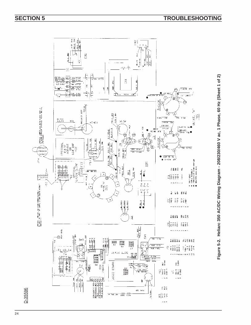
24
Figu
re 5
-2.
Hel
iarc
350
AC
/DC
Wiri
ng D
iagr
am -
208/
230/
460
V ac
, 1 P
hase
, 60
Hz
(She
et 1
of 2
)

SECTION 5 TROUBLESHOOTING
25
Figu
re 5
-2.
Hel
iarc
350
AC
/DC
Wiri
ng D
iagr
am -
208/
230/
460
V ac
, 1 P
hase
, 60
Hz
(She
et 2
of 2
)
♦In
stal
led
in u
nits
with
Pow
er F
acto
rC
orre
ctio
n (P
FC
).
Opt
iona
l fo
r un
itsw
ithou
t P
FC
.
♦

SECTION 5 TROUBLESHOOTING

SECTION 6 REPLACEMENT PARTS
26
6.1 GENERAL
Replacement Parts are illustrated on the followingfigures. When ordering replacement parts, order bypart number and part name, as illustrated on the figure.DO NOT ORDER BY PART NUMBER ALONE.
Always provide the series or serial number of the uniton which the parts will be used. The serial number isstamped on the unit nameplate.
6.2 ORDERING
To assure proper operation, it is recommended thatonly genuine ESAB parts and products be used withthis equipment. The use of non-ESAB parts may voidyour warranty.
Replacement parts may be ordered from your ESABdistributor or from:
ESAB Welding & Cutting ProductsAttn: Customer Service Dept.PO Box 100545, Ebenezer RoadFlorence, SC, 29501-0545
Be sure to indicate any special shipping instructionswhen ordering replacement parts.
To order parts by phone, contact ESAB at 1-803-664-5540 or 4460. Orders may also be faxed to 1-800-634-7548. Be sure to indicate any special shipping instruc-tions when ordering replacement parts.
Refer to the Communication Guide located on the lastpage of this manual for a list of customer service phonenumbers.

SECTION 6 REPLACEMENT PARTS
27
TOP COVER - 30589YLWARNING DECAL - 2091514
(F1) 5 AMP FUSE - 97W06FUSEHOLDER - 182W15
(2) HANDLES - 30596
UPPER PANEL SILKSCREENED - 31063(2) OUTPUT TERMINAL ASSYS. - 676740
†LOW AMP KIT - P/N 680631; Includes: SILKSCREEN MTG. PLATE - 680932,ON-OFF SW. ASSY. - 680934, SW. KNOB - 2062171, INDUCTOR ASSY, -680953 (For Mtg. Location, See Left Side View).
(HFI) H.F. INTENSITY RHEOSTAT - 993439KNOB - 950584
(PFP) KNOB - 950584POSTFLOW CONTROL POT & HI FREQ CONTROLSW. Are Integral Part of LOGIC P.C.BOARD ASSY. - 675421
BALANCE CONTROL Includes:(BP) BAL. POTENTIOMETER - 639541KNOB - 950584RESISTOR ASSY - 30157, Includes:(R101) 221K, 1% - 17111422(R102) 1 MEG, 1% - 17111510
(AFP) KNOB - 950584ARC FORCE CONTROL POT & SOFT START SW.Are Integral Part of SOFT START P.C.BOARD ASSY. - 675492
(SW1) TIG-STICK SW. 950812
(ROS) ON-OFF POWER SW. - 950945
(J4) REMOTE CONTACTOR RECPT. - 84W31(C-25, -26) CAPACITOR - 674216
(J3) REMOTE CURRENT RECPT. - 98W10(C-22, -23, -24) CAPACITOR - 674216
(CSS) CURRENT SELECT SW. - 680676KNOB - 2062171(C-10, -13) CAPACITOR - 950702
H.F. ENCLOSURE COVER (Not Shown) - 30592
(HFTR) H.F. TRANSFORMER - 950573
(SG) SPARK GAP ASSY. - 680036Includes:P.C. BOARD ASSY. - 675425(2) HEAT SINKS - 673579(2) SPARK GAP POINTS - 673578(1) CAPACITOR - 950256
(FCT) H.F. FERRITE CORE TRANSF. - 30573
WATER BULKHEAD ADAPTOR, L.H. "B"FEMALE TO 1/4" NPT MALE - 58V753/16" HOSE NIPPLE, 1/4" NPT FEMALE - 950510
PLUMBING/OUTPUT TERMINALSILKSCREEN PANEL - 30601GYPLUMBING/OUTPUT TERMINALCOVER (Not Shown) - 30593GY
LOCATION FOR OPTIONAL ANALOG METERMODULE - 680628 (See Fig. 6-5)
(SW2) PANEL-REMOTE CURRENT SW. - 950812
(HIGH-LOW CURRENT RANGE SW. Is Integral Partof SCR CONTROL P.C. BOARD ASSY. - 674976*)
(CCP) CURRENT CONTROL POT. ASSY. - 31065*(CCP) KNOB - 950584
LOCATION FOR OPTIONAL SLOPE/SPOTWELDCONTROL MODULE - 680665 (See Fig. 6-6)
BLANK PLATE (680660) LOCATION FOR:(OPTIONAL) LOW AMP KIT - 680631†; OR(OPTIONAL) PANEL-MT'D. PULSECONTROL MODULE - 680693 (See Fig. 6-7)
WATER DRAIN & TORCH GAS POWEROUTPUT BLOCK ASSY. - 30612
Figure 6-1. Heliarc 350 AC/DC (Front View)

SECTION 6 REPLACEMENT PARTS
28
Reference: T5 Terminal STANDOFF
DUST COVER (Not Shown) - 680675
(F2) FUSE, 1/2 AMP - 996523FUSE BLOCK - 96W10
(TSR) RELAY - 950760
(BR) BRIDGE ASSY. - 30584(Also see Fig. 6-4)
(T2) 5 POS. TERM. STRIP - 950826(R10) RESISTOR, 10K, 1/2w - 17125310(D3) DIODE, 1N4007 - 950415
(R105) RES. 100 ohm, 50w - 17250110(Bet. Work Term & Chassis Ground)
(R6) RESISTOR, 150 ohm, 50w - 17250115(R7) RESISTOR, 10 ohm, 50w - 17250010
(FN1) FILTER NETWORK ASSY. - 674971
Figure 6-2. Heliarc 350 AC/DC (Left Side View)
(R3, R104) RESISTOR, 8 ohm, 300w - 17300008(2-ea.) CENTERING WASHERS - 91W19(2-ea.) MICA WASHERS - 647182
RIGHT SIDE PANEL (Not Shown) -30590YLRIGHT SIDE T.B. COVER (NotShown) - 30429YL
GROUND TERM. LUG - 647361
INPUT TERMINAL BOARDASSY. - 680047
(HRTR) REACTOR - 30581(RTSA, RTSB) THERMAL SWS. 180 °C -2062211 (One inserted in each coil).
FAN BLADE - 672189FAN SHROUD - 672330
(FM) FAN MOTOR - 2062334
15 AMP CIRCUIT BKR. - 950188
115 VAC Duplex Outlet - 647298
(MTR) MAIN TRANSF - 30577(TSA, TSB) THERMAL SWS, 160 °C -673374 (One inserted each winding)
(T1) 5 POS. TERM. STRIP - 950826
SILKSCREEN REAR PANEL - 30599
Figure 6-3. Heliarc 350 AC/DC (Right Side View)
(T4) 5 POS. TERM. STRIP - 950286
MOUNTING LOCATION FOR, OPTIONALLOW AMP KIT (P/N 680631),INDUCTOR ASSY. - 680953
MOUNTING LOCATION FOR POWERFACTOR KIT CAPACITORS (Factory-installed in units with power factor correction)P.F. KIT - P/N 680632, Includes:(3) CAP., 60 µF, 440 VAC - 950519(1) MOUNTING BRACKET - 678619
WATER BULKHEAD ADAPTOR L.H. "B"FEMALE TO 1/4" NPT MALE - 58V753/16" HOSE NIPPLE, 1/4" NPT FEMALE -950510
GAS BULKHEAD ADAPTOR, R.H. "B" FEMALETO 1/4" NPT MALE - 58V58(GSV) GAS SOLENOID VALVE - 9502493/16" HOSE NIPPLE, 1/4" NPT MALE - 950263(R9) RESISTOR, 470 ohm, 2w - 17140147
(R106) RESISTOR, 20 ohm, 300w - 17300020(2) CENTERING WASHERS - 91W19(2) MICA WASHERS - 647182
(FN2) FILTER NETWORK - 680042Includes:(MOV) MET. OXIDE VARISTOR - 995104(C1, C2) 0.01 µF, 125v - 950702(C3) 1.0 µF, 600 v - 993716
(C11) CAP, 10 µF, 370 v - 672772
LEFT SIDE PANEL (Not Shown) - 30591YL

SECTION 6 REPLACEMENT PARTS
29
Figure 6-6. Slope/Spotweld Control Module(P/N 680665)
Figure 6-5. Analog Meter Module (P/N 680628)
Figure 6-4. Bridge Assembly (P/N 30584)

SECTION 6 REPLACEMENT PARTS
30
Figure 6-7. Panel Pulse Control Assembly(P/N 680693)

SECTION 6 REPLACEMENT PARTS
31

Notes

F-14-447-A 4/95 1.5M Printed in U.S.A.
ESAB Welding & Cutting ProductsPO Box 100545 Florence SC 29501-0545
COMMUNICATIONS GUIDE
A. CUSTOMER SERVICE QUESTIONS: Telephone: (803) 664-5540 / FAX: (800) 634-7548Order Entry Product Availability Pricing Order Changes Hours: 8:30 AM to 5:00 PM EST
B. ENGINEERING SERVICE: Telephone: (803) 664-4416 or -5550 / FAX: (800) 446-5693Welding Equipment Troubleshooting Warranty Returns Hours: 7:30 AM to 5:00 PM EST
C. TECHNICAL SERVICE: Telephone: (803) 664-5547 / FAX: (803) 664-5575Part Numbers Technical Applications Hours: 7:30 AM to 5:00 PM ESTPerformance Features Technical Specifications
D. LITERATURE REQUESTS: Telephone: (803) 664-5501 / FAX: (803) 664-5575Hours: 7:30 AM to 4:00 PM EST
E. WELDING EQUIPMENT REPAIRS: Telephone: (803) 664-4487 / FAX: (803) 664-5557Repair Estimates Repair Status Hours: 7:30 AM to 3:30 PM EST
F. WELDING EQUIPMENT TRAINING: Telephone: (803) 664-5524 / FAX: (803) 664-5575Training School Information and Registrations Hours: 7:30 AM to 4:00 PM EST
G. WELDING PROCESS ASSISTANCE: Telephone: (803) 664-4248 / FAX: (803) 664-4454Hours: 7:30 AM to 4:00 PM EST
H. TECHNICAL ASST. CONSUMABLES: Telephone: (800) 934-9353Hours: 7:30 AM to 5:00 PM EST
IF YOU DO NOT KNOW WHOM TO CALL
Telephone: (803) 664-5540 and (803) 664-4460
Hours: 7:30 AM to 5:00 PM EST