Embed Size (px)
Citation preview

Heavy Duty Pressure TransducersPX2 Series1 bar to 46 bar | 100 kPa to 4.6 MPa | 15 psi to 667 psi
Datasheet

2 sensing.honeywell.com
Heavy Duty Pressure TransducersHoneywell’s PX2 Series Heavy Duty Pressure Transducer is a portfolio of highly configurable pressure sensors that use piezoresistive sensing technology with ASIC (Application Specific Integrated Circuit) signal conditioning in a stainless steel housing. The PX2 Series is fully calibrated and compensated for offset, sensitivity, temperature effects and non-linearity using the on-board ASIC. This provides a Total Error Band of ±2% over the operating temperature range of -40 ºC to 125 ºC [-40 °F to 257 °F].
With thousands of possible configurations, the PX2 Series allows Honeywell to meet customer requirements and quickly provide samples. New standard configurations are regularly being added.
The PX2 Series is compatible with a variety of harsh media including brake fluid, refrigerants, engine oil, tap water, hydraulic fluids, and compressed air. The wide operating temperature range, ingress protection up to IP69K, and 100 V/m radiated immunity allow for reliable performance in tough environments.
These transducers measure absolute or sealed gage pressure. The absolute versions have an internal vacuum reference and an output value proportional to absolute pressure. The sealed gage versions have an internal pressure reference of one atmosphere at sea level.
The PX2 Series is available in three pressure ranges, with additional pressure ranges coming soon.
• 1 bar to 46 bar
• 100 kPa to 4.6 MPa
• 15 psi to 667 psi
All products are RoHS compliant and are designed and manufactured according to ISO 9001 standards.
Count on affordability and availability with these high performing, durable transducers.
AFFORDABLE • AvAiLABLE • high pERFORmAncE
What makes our transducers better? Affordable: Competitive product cost, over
15,000 standard configurations, and global application support
Available: Wide selection of features and a short lead time for samples and production parts
High performance: Small Total Error Band, fast response time, and long life
High durability: Environmentally tough, wide operating temperature range, and ability to withstand mechanical shock and vibration

3sensing.honeywell.com
COST EFFECTIVE*The PX2 Series is a precise pressure measurement solution that optimizes system performance at a competitive cost.
DESIGNED FOR CONFIGURABILITY*With over 15,000 standard configurations, the PX2 Series easily meets our customers’ specific application needs.
APPLICATION EXPERTISE*Knowledgeable application engineers are available to answer customers’ specific design questions during the development of their product.
GLOBAL SUPPORTHoneywell’s global presence offers customers immediate product and application support throughout the development cycle, from design to global manufacturing.
WIDE SELECTION OF OPTIONSNumerous standard or custom connectors, ports, pressure ranges and types, and output options include: • Connector types: Delphi Metri-Pack 150, Micro M12, DIN, Deutsch, cable harness (1 m, 2 m, 3 m, or 5 m). • Port types: 1/4-18 NPT, 1/8-27 NPT, 9/16-18 UNF SAE J1926-3, 7/16-20 UNF SAE J1926-3, 1/4 in 45° Flare Female Schrader (7/16-20 SAE J512), M12 x 1.5 ISO 6149-3, G1/4 ISO 1179-3, G1/8 ISO 1179-3. • Pressure range: 1 bar to 46 bar | 100 kPa to 4.6 MPa | 15 psi to 667 psi. • Pressure reference: Absolute or sealed gage. • Output transfer function: Ratiometric, regulated or current.
SHORT LEAD TIME Due to the PX2 Series’ configurability, customers can count on a quick response to prototypes. Additionally, dedicated teams and manufacturing processes ensure that product samples are shipped quickly to support your demanding product development cycle.
*Competitive Differentiator
Affordability minimizes your cost to produce.
Features and Benefits
Available feature-rich and fast.

4 sensing.honeywell.com
SMALL TOTAL ERROR BAND (TEB)Honeywell specifies TEB, the most comprehensive, clear, and meaningful measurement that provides the transducer’s true accuracy over a compensated temperature range of -40 °C to 125 °C [-40 °F to 257 °F] (see Figure 1).
The PX2 Series’ industry-leading TEB of ±2%: • Provides excellent transducer interchangeability due to minimal part-to-part variation in accuracy. • Eliminates the customers’ need for individual transducer testing and calibration. • Supports system accuracy and warranty requirements.
FAST RESPONSE TIMEA fast response time of <2 ms helps maximize system performance.
LONG LIFEA minimum 10 million cycles to operating pressure provides long life in the application.
Features and Benefits
Dependable, consistent performance.
+
+
+
+
+
Pressure Non-Linearity
Pressure Hysteresis
Pressure Non-Repeatability
All Possible Errors
+
+
Offset
Full Scale Span
Thermal Effect on Offset
Thermal Effect on Span
Thermal Hysteresis
TotalError Band
Accuracy=
=
Figure 1: TEB For the PX2 Series

5sensing.honeywell.com
Durability improves output and endurance.
*Competitive Differentiator
Features and Benefits
ENVIRONMENTALLY TOUGHCompatibility with a wide variety of harsh media, up to IP69K ingress protection, and 100 V/m radiated immunity allow for use in tough environments.
WIDE OPERATING TEMPERATURE RANGEA compensated operating temperature range of -40 °C to 125 °C [-40 °F to 257 °F] allows customers to design the same sensor into a variety of applications.
SHOCK AND VIBRATION RESISTANTA mechanical shock rating of 100 G per MIL-STD-202F, Method 213B, Cond. F, and a vibration rating of 20 G sweep, 10 Hz to 2000 Hz, increase flexibility of use within the application.
GOOD EMC PROTECTIONProvides confidence that the transducer will not be damaged by environmental electromagnetic interference. Radiated immunity protection up to 100 V/m (ISO 11452-2) is available.
ENERGY EFFICIENT*AC and AD output transfer functions offer a 3.3 V ratiometric output with a <7 ms turn on time, enabling the PX2 Series to be used when energy efficiency is a key requirement.
SIX SIGMA DESIGN STANDARDS*Results in the highest level of quality, performance, and consistency so that customers are assured that the transducer will perform to specification.

6 sensing.honeywell.com
INDUSTRIAL
HVAC/R
May be used to monitor system performance for proper environmental control of: • Compressor inlet and outlet pressure • Rooftop chillers • Compressor rack rooms • Refrigerant recovery systems • Compressor oil pressure
AIR COMPRESSORS
May be used to monitor compressor performance and efficiency, specifically: • Compressor inlet and outlet pressure • Cooling water inlet and outlet pressure • Compressor oil pressure • Filter pressure drop
GENERAL
May be used to monitor: • Emissions monitoring • Factory automation • Flow and level • Fluid power • Foam dispensing • Injection molding knock-out valves • Lasers • Laminating equipment • Packaging equipment • Pneumatics • Pumps • Solar energy • Sprayers • System pressure • Valves
Potential Applications

7sensing.honeywell.com
Heavy Duty Pressure Transducers
Table 1. Electrical Specifications
Characteristic
Ratiometric OutputCurrent Output
Regulated Output
Output Transfer Function Order Code (See Figure 5.)
AA AB AC AD CH BC BD BE BG
Output transfer function1: null output value full scale output value full scale span (FSS) operating supply voltage, min.(Vs)2
operating supply voltage, typ. (Vs)2
operating supply voltage, max. (Vs)2
10% of Vs90% of Vs80% of Vs
4.75 V5 V
5.25 V
5% of Vs95% of Vs90% of Vs
4.5 V5 V
5.5 V
10% of Vs90% of Vs80% of Vs
3.135 V3.3 V
3.465 V
5%of Vs95% of Vs90% of Vs
3.135 V3.3 V
3.465 V
4 mA4 mA16 mA
8 V—
30 V4
1 V6 V5 V9 V—
30 V3
0.25 V10.25 V
10 V13 V—
30 V3
0.5 V4.5 V4 V8 V—
30 V3
1 V5 V4 V8 V—
30 V3
Supply current (typ.) 5 mA 4 mA — 5.5 mA
Output load (pull up or down) minimum maximum
2 kOhm—
—(Vs - 8) x 50 Ohm4
2 kOhm—
Absolute voltage ratings5: minimum6
maximum6
maximum applied to output pin
-16 V16 VVs
-16 V30 V—
-16 V30 V12 V
EMC rating — CE compliance7: electrostatic discharge radiated immunity fast transient burst immunity to conducted disturbances radiated emissions
±4 kV contact, ±8 kV air per IEC 61000-4-210 V/m (80 MHz to 1000 MHz) per IEC 61000-4-3
±1 kV per IEC61000-4-43 V per IEC61000-4-6
40 dB 30 MHz to 230 MHz; 47 dB 230 MHz to 1000 MHz per CISPR 11
EMC rating – ISO 11452-27:
radiated immunity 100 V/m 200 MHz to 2 GHz 20 V/m 200 MHz to 2 GHz
1Output transfer function options are shown in the Nomenclature and Order Guide. (See Figure 5.)
2Transducer will not produce valid output when supply voltage is outside of operating range.
3Applies at 25 °C. See Figure 2 for Regulated Output Supply Voltage.
4Applies at 25 °C. See Figure 3 for Current Output Supply Voltage.
5Absolute maximum ratings are the extreme limits the device can withstand without damage to the product. Voltages above these ratings may cause permanent damage. Exposure to absolute maximum conditions for extended periods may degrade device reliability.
6Absolute voltage applies to potential across power and ground terminals.
7All EMC ratings verified with the Delphi Metri-Pack 150 connector type.

8 sensing.honeywell.com
PX2 Series
Figure 4. Pressure Rating Curve
Figure 2. Regulated Output Supply Voltage Figure 3. Current Output Supply Voltage
Pres
sure
Rat
ing
(psi
)
Operating Pressure (psi)
Overpressure Burst Pressure
0 50 100 150 2000
750
400
600
1000
1250
1500
667250 30015 30
11570
250150
450

9sensing.honeywell.com
Heavy Duty Pressure Transducers
Table 2. Performance Specifications1
Characteristic Parameter
Operating temperature range2 -40 °C to 125 °C [-40 °F to 257 °F]
Storage temperature range3 -40 °C to 125 °C [-40 °F to 257 °F]
Compensated temperature range4 -40 °C to 125 °C [-40 °F to 257 °F]
Overpressure minimum rating5 (See Figure 4.)
Burst pressure minimum rating6 (See Figure 4.)
Long term stability ±0.5 %FSS9 (1000 hr at 25 °C [77 °F])
Accuracy7 ±0.25 %FSS9 (See Figure 1.)
Offset error8 ±1 %FSS9
Total Error Band10 ±2 %FSS9 (-40 °C to 125 °C [-40°F to 257 °F]) (See Figure 1.)
Response time11 <2 ms
Turn on time12 <7 ms
Life13 min. of 10 million cycles to operating pressure
1All specifications apply at 25 °C and under operating conditions unless otherwise noted.
2Operating Temperature Range: The temperature range over which the product will produce an output proportional to pressure but may not remain within the specified performance limits.
3Storage Temperature Range: The temperature range over which the product may safely be exposed without excitation or pressure applied. Under these conditions the product will remain in specification after excursion to any temperatures within this range. Exposure to temperatures outside this range may cause permanent damage to the product.
4Compensated Temperature Range: The temperature range (or ranges) over which the product will produce an output proportional to pressure within the specified performance limits.
5Overpressure: The absolute maximum rating for pressure which may be safely applied to the product for it to remain in specification once pressure is returned to the operating pressure range. Exposure to higher pressure may cause permanent damage to the product.
6Burst Pressure: The maximum pressure that may be applied to the product without causing escape of the pressure media. The product should not be expected to function after exposure to any pressure beyond the rated burst pressure. This rating is also the case burst rating of the product.
7Accuracy: The maximum deviation in output from a Best Fit Straight Line (BFSL) fitted to the output measured over the pressure range at 25 °C. Includes all errors due to pressure non-linearity, pressure hysteresis, and non-repeatability.
8Offset Error: the maximum deviation in the output signal obtained when the reference pressure is applied at 25 °C relative to the ideal transfer function.
9Full Scale Span (FSS): The algebraic difference between the output signal measured at the maximum (Pmax.) and minimum (Pmin.) limits of the pressure range.
10Total Error Band: The maximum deviation from the ideal transfer function over the entire compensated temperature and pressure range. Includes all errors due to offset, full scale span, pressure non-linearity, pressure hysteresis, repeatability, thermal effect on offset, thermal effect on span, and thermal hysteresis.
11Response Time: The response time of the transducer is the maximum amount of time that the transducer will take for the transducer to output a change from 10% to 90% of full scale in response to a 0% to 100% full scale step input pressure range.
12Turn On Time: Duration from power applied until first valid output.
13Life may vary depending on the application in which transducer is used. Contact Honeywell Sales and Service for Mean Time to Failure (MTTF) data based on customer-specific usage profile.

10 sensing.honeywell.com
PX2 Series
Table 4. Mechanical Characteristics
Characteristic Parameter
Mechanical shock 100 G per MIL-STD-202F, Method 213B, Cond. F (at 25 °C)
Vibration 20 G sweep, 10 Hz to 2000 Hz (at 25 °C)
Enclosure rating per electrical connector selection (See Figure 7.)
Wetted materials: port substrate adhesives electronics
304 stainless steel alumina ceramic
epoxyglass, silicon
External materials: housing connector cable jacket
304 stainless steelPBT 30% GF
TPE
Installation torque per port type (See Figure 8.)
Table 3. Pressure Types
Pressure Reference Description
AbsoluteOutput is proportional to the difference between applied pressure and a built-in fixed reference to vacuum (zero pressure), where the minimum operating pressure is set to absolute zero pressure
(perfect vacuum)
Sealed Gage1Output is proportional to the difference between applied pressure and a built-in fixed reference to
1 atmsA, where the minimum operating pressure is set to 14.7 psiA (1 atmsA)
1Sealed gage option only available in pressure ranges at or above 100 psi.

11sensing.honeywell.com
Heavy Duty Pressure Transducers
Figure 5. Nomenclature and Order Guide1
ConnectorType
Sensor(Series)
Port Type
PX2 A N1 XX 150P A BD X
(three-wire)
(two-wire)
SA
Series
Pressure Reference
A
D
DelphiMetri-Pack 1502
DeutschDTM04-3P
Connector Type
E Cable harness,1 meter3
N1
N2
1/4-18 NPT
1/8-27 NPT
Port Type
S1 9/16-18 UNFSAE J1926-3
PX2 Heavy Duty Pressure Transducer1
S2 7/16-20 UNFSAE J1926-3
002B1.6B001B 1 bar
1.6 bar
2 bar
Pressure Range
Absolute
Sealed gage5
AAAB
Ratiometric 5.0 V, 10 %Vs to 90 %Vs
Ratiometric 5.0 V, 5 %Vs to 95 %Vs
Output Transfer Function
AC Ratiometric 3.3 V, 10 %Vs to 90 %Vs
AD Ratiometric 3.3 V, 5 %Vs to 95 %Vs
BC Regulated, 1 Vdc to 6 Vdc
BD Regulated, 0.25 Vdc to 10.25 Vdc
BE Regulated, 0.5 Vdc to 4.5 Vdc
BG Regulated, 1 Vdc to 5 Vdc
CH Current, 4 mA to 20 mAB Micro M12 IEC 61076-2
C DIN EN 175301-803C
F Cable harness,2 meter3
G Cable harness,3 meter3, 4
H Cable harness,5 meter3, 4
2.5B 2.5 bar
004B 4 bar
F1
M1 M12 x 1.5ISO 6149-3
G1 G1/4ISO 1179-3
G2G1/8ISO 1179-3
1/4 in 45º FlareFemale Schrader(7/16-20 SAE J512)
100P 100 psi
200P250P
150P 150 psi
250 psi
200 psi
300P500P 500 psi
300 psi
600P 600 psi
667P 667 psi
1Not all catalog listing combinations are available. Custom products are available. Please contact Honeywell. 2Mating connectors available from Honeywell are 3685301 (1 m cable length) and 3685302 (3 m cable length). 3Three-wire cable is required for ratiometric and regulated outputs; two-wire cable is required for current output.4Three meter and �ve meter cables are only available with Output Transfer Function CH = Current, 4 mA to 20 mA.5Sealed gage option only available in pressure ranges at or above 100 psi.
bar psi
008B006B 6 bar
8 bar
010B 10 bar
016B 16 bar
040B025B 25 bar
40 bar
046B 46 bar
100K 100 kPa
250K160K 160 kPa
250 kPa
400K 400 kPa
600K 600 kPa
Pa015P030P 030 psi
015 psi
050P 050 psi
For example, PX2AN1XX150PABDX de�nes a PX2 Series Heavy Duty Pressure Transducer, Delphi Metri-Pack 150 connector type,1/4-18 NPT port type, 150 psi pressure range, absolute pressure reference, regulated, 0.25 Vdc to 10.25 Vdc output transfer function.
001G 1 MPa
2.5G1.6G 1.6 MPa
2.5 MPa
004G 4 MPa
4.6G 4.6 MPa

12 sensing.honeywell.com
PX2 SeriesFigure 6. All Available Standard External Configurations
Connector Type
Port Type
1/4-18 NPT 1/8-27 NPT 9/16-18 UNF SAE J1926-3
7/16-20 UNF SAE J1926-3
1/4 in 45º Flare Female
Schrader(7/16-20 SAE
J512)
M12 X 1.5 ISO 6149-3
G1/4 ISO 1179-3
G1/8 ISO 1179-3
DelphiMetri-Pack 150
Micro M12 IEC 61076-2
DIN EN 175301-803C
Deutsch DTM04-3P
Cable Harness:
1 Meter2 Meter3 Meter5 Meter

13sensing.honeywell.com
Heavy Duty Pressure TransducersFigure 7. Connector Dimensions (For reference only: mm/[in].)
A = Delphi Metri-Pack 150 B = Micro M12 IEC 61076-2 C= DIN EN 175301-803C
Connector: DELPHI 12078088Mating Connector: DELPHI 12110192
IP Rating1: IP65
Connector: IEC 61076-2-101Mating Connector: 4 POS TYPE D
IP Rating1: IP65/IP67
Connector: EN 175301-803CMating Connector: EN 175301-803C DIN
43650C 8MMIP Rating1: IP65
Pin VoltageOutput
CurrentOutput
PinVoltageOutput
CurrentOutput
PinVoltageOutput
CurrentOutput
A GND RTN 1 V+ supply 1 GND RTN
B V+ supply 3 GND RTN 2 V+ supply
C Vout NC 4 Vout NC
3 Vout NC
PE NC NC
1IP rating is determined by the electrical connection chosen.

14 sensing.honeywell.com
PX2 SeriesFigure 7. Connector Dimensions, Continued (For reference only: mm/[in].)
D = Deutsch DTM04-3P
E = Cable Harness, 1 Meter2
F = Cable Harness, 2 Meter2
G = Cable Harness, 3 Meter2, 3
H = Cable Harness, 5 Meter2, 3
Connector: Deutsch DTM04-3PMating Connector: DTM06-3S
IP Rating1: IP65, IP67, IP69K
Connector: 24 AWG with TPE JacketMating Connector: Flying leads
IP Rating1: IP65, IP67, IP69K
Pin VoltageOutput
CurrentOutput
Wire ColorVoltageOutput
Wire ColorCurrentOutput
1 V+ supply red V+ red supply
2 Vout NC black GND
black RTN3 GND RTN white Vout
1IP rating is determined by the electrical connection chosen.2Three-wire cable is required for ratiometric and regulated outputs; two wire cable is required for current output.3Three meter and five meter cables are only available with Output Transfer Function CH = Current, 4 mA to 20 mA.

15sensing.honeywell.com
Heavy Duty Pressure TransducersFigure 8. Port Dimensions (For reference only: mm/[in].)
N1 = 1/4–18 NPT N2 = 1/8–27 NPT
Seal: pipe threadMating Geometry: ANSI B1.20.1
Installation Torque1: 2 to 3 Turns From Finger Tight
Seal: pipe threadMating Geometry: ANSI B1.20.1
Installation Torque1: 2 to 3 Turns From Finger Tight
S1 = 9/16–18 UNF SAE J1926-3 S2 = 7/16–20 UNF SAE J1926-3
Seal2,3: O-ringMating Geometry: SAE J1926-1
Installation Torque1: 30 N m [22.1 ft lb]
Seal2,3: O-ringMating Geometry: SAE J1926-1
Installation Torque1: 18 N m [12.3 ft lb]
F1 = 1/4 in 45º Flare Female Schrader (7/16–20 SAE J512) M1 = M12 X 1.5 ISO 6149-3
Seal: 45º cone sealMating Geometry: SAE J512
Installation Torque1: 17 N m [12.5 ft lb]
Seal2,3: O-ringMating Geometry: ISO 6149-1
Installation Torque1: 25 N m [18.4 ft lb]
G1 = G1/4 ISO 1179-3 G2 = G1/8 ISO 1179-3
Seal2,3: O-ringMating Geometry: ISO 1179-1
Installation Torque1: 50 N m [38.9 ft lb]
Seal2,3: O-ringMating Geometry: ISO 1179-1
Installation Torque1: 25 N m [18.4 ft lb]
1Straight thread maximum torque is validated to 150% of installation torque.2Seals for port order codes S1, S2, M1, G1 and G2 are included and assembled to the sensor.3O-ring material is nitrile 70 durometer -30 ºC to 125 ºC [-22 ºF to 257 ºF].
16 sensing.honeywell.com
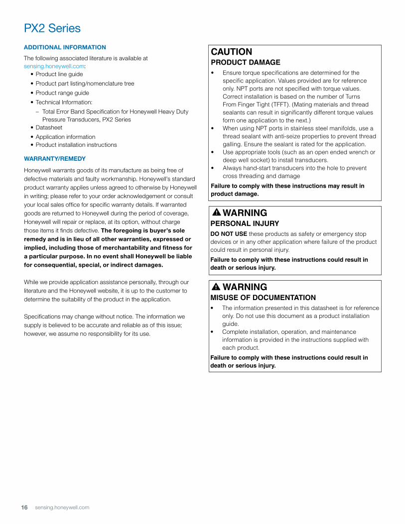
PX2 SeriesADDITIONAL INFORMATION
The following associated literature is available atsensing.honeywell.com: • Product line guide
• Product part listing/nomenclature tree
• Product range guide
• Technical Information:
– Total Error Band Specification for Honeywell Heavy Duty Pressure Transducers, PX2 Series • Datasheet
• Application information • Product installation instructions
WARRANTY/REMEDY
Honeywell warrants goods of its manufacture as being free of defective materials and faulty workmanship. Honeywell’s standard product warranty applies unless agreed to otherwise by Honeywell in writing; please refer to your order acknowledgement or consult your local sales office for specific warranty details. If warranted goods are returned to Honeywell during the period of coverage, Honeywell will repair or replace, at its option, without charge those items it finds defective. The foregoing is buyer’s sole remedy and is in lieu of all other warranties, expressed or implied, including those of merchantability and fitness for a particular purpose. In no event shall Honeywell be liable for consequential, special, or indirect damages.
While we provide application assistance personally, through our literature and the Honeywell website, it is up to the customer to determine the suitability of the product in the application.
Specifications may change without notice. The information we supply is believed to be accurate and reliable as of this issue; however, we assume no responsibility for its use.
WARNINGPERSONAL INJURYDO NOT USE these products as safety or emergency stop devices or in any other application where failure of the product could result in personal injury.
Failure to comply with these instructions could result in death or serious injury.
WARNINGMISUSE OF DOCUMENTATION• Theinformationpresentedinthisdatasheetisforreference
only. Do not use this document as a product installation guide.
• Completeinstallation,operation,andmaintenanceinformation is provided in the instructions supplied with each product.
Failure to comply with these instructions could result in death or serious injury.
CAUTIONPRODUCT DAMAGE• Ensuretorquespecificationsaredeterminedforthe
specificapplication.Valuesprovidedareforreferenceonly.NPTportsarenotspecifiedwithtorquevalues.CorrectinstallationisbasedonthenumberofTurnsFromFingerTight(TFFT).(Matingmaterialsandthreadsealantscanresultinsignificantlydifferenttorquevaluesformoneapplicationtothenext.)
• WhenusingNPTportsinstainlesssteelmanifolds,useathread sealant with anti-seize properties to prevent thread galling.Ensurethesealantisratedfortheapplication.
• Useappropriatetools(suchasanopenendedwrenchordeepwellsocket)toinstalltransducers.
• Alwayshand-starttransducersintotheholetopreventcross threading and damage
Failure to comply with these instructions may result in product damage.

50069942 Rev. F - ENFebruary 2014© 2014 Honeywell International Inc. All rights reserved.
Sales and ServiceHoneywell serves its customers through a worldwide network of sales offices, representatives and distributors. For application assistance, current specifications, pricing or name of the nearest Authorized Distributor, contact your local sales office or email us at [email protected]. Visit us on the Web at sensing.honeywell.com
Phone and Fax:Asia Pacific +65 6355-2828 +65 6445-3033 FaxEurope +44 (0) 1698 481481 +44 (0) 1698 481676 FaxLatin America +1-305-805-8188 +1-305-883-8257 FaxUSA/Canada +1-800-537-6945 +1-815-235-6847 +1-815-235-6545 Fax
Sensing and Control
Honeywell
1985 Douglas Drive North
Golden Valley, MN 55422
honeywell.com