Embed Size (px)
Citation preview

Document type: European Standard Document subtype: Document stage: Formal Vote Document language: E C:\Mine dokumenter\TC 228\WG 4\WI 00228033\TC version\N559_prEN 15316-3-2_WI00228033_2006-08.doc STD Version 2.1c
Doc. CEN/TC 228 N559 CEN/TC 228 Date: 2006-08
CEN/TC 228 WI 033
CEN/TC 228
Secretariat: DS
Heating systems in buildings — Method for calculation of system energy requirements and system efficiencies — Part 3-2: Domestic hot water systems, distribution
Einführendes Element — Haupt-Element — Teil 3.2: Ergänzendes Element
Élément introductif — Élément central — Partie 3.2 : Élément complémentaire
ICS:
Descriptors:

prEN 15316-3-2:2006 (E)
2
Contents Page
1 Scope ......................................................................................................................................................5 2 Normative references ............................................................................................................................5 3 Terms and definitions ...........................................................................................................................5 4 Symbols and Units.................................................................................................................................6 5 Domestic hot water system characteristics........................................................................................7 6 Distribution heat losses ........................................................................................................................9 7 Auxiliary energy.................................................................................................................................. 14 8 Recoverable, recovered and unrecoverable heat losses ............................................................... 16 Annex A (informative) Calculation of heat emission from pipes based on domestic hot water
delivery pipe lengths – simple calculation method......................................................................... 17 Annex B (informative) Calculation of heat emission from pipes based on domestic hot water
delivery pipe lengths – tabulated data method ............................................................................... 18 Annex C (informative) Calculation of heat emission from pipes based on domestic hot water
tapping profiles ................................................................................................................................... 20 Annex D (informative) Calculation of heat emission from domestic hot water pipes............................. 22 Annex E (informative) Calculation of heat loss from user outlets ............................................................ 28 Annex F (informative) Calculation of energy requirement of a circulation pump ................................... 29

prEN 15316-3-2:2006 (E)
3
Foreword
This document (prEN 15316-3-2:2005) has been prepared by Technical Committee CEN/TC 228 “Heating systems in buildings”, the secretariat of which is held by DS.
The subjects covered by CEN/TC 228 are the following:
- design of heating systems (water based, electrical etc.);
- installation of heating systems;
- commissioning of heating systems;
- instructions for operation, maintenance and use of heating systems;
- methods for calculation of the design heat loss and heat loads;
- methods for calculation of the energy performance of heating systems.
Heating systems also include the effect of attached systems such as hot water production systems.
All these standards are systems standards, i.e. they are based on requirements addressed to the system as a whole and not dealing with requirements to the products within the system.
Where possible, reference is made to other European or International Standards, a.o. product standards. However, use of products complying with relevant product standards is no guarantee of compliance with the system requirements.
The requirements are mainly expressed as functional requirements, i.e. requirements dealing with the function of the system and not specifying shape, material, dimensions or the like.
The guidelines describe ways to meet the requirements, but other ways to fulfil the functional requirements might be used if fulfilment can be proved.
Heating systems differ among the member countries due to climate, traditions and national regulations. In some cases requirements are given as classes so national or individual needs may be accommodated.
In cases where the standards contradict with national regulations, the latter should be followed.

prEN 15316-3-2:2006 (E)
4
Introduction
This document is one of three documents that together describe methods for calculation of system energy requirements and system efficiencies related to domestic hot water systems. In particular this document describes methods for calculating the energy losses due to the distribution system.
The user shall refer to other European standards or to National documents for input data and detailed calcula-tion procedures not provided by this standard.
Only the calculation methods are normative. All the values necessary to complete the calculations are to be given in a National Annex.

prEN 15316-3-2:2006 (E)
5
1 Scope
This standard is part of a set of standards covering methods for the calculation of system energy requirements and system efficiencies of heating systems in buildings. In particular this standard is one of a number of standards dealing with domestic hot water systems.
The scope of this specific part is to standardise the methods for calculation of heat losses from the domestic hot water distribution system and it defines the:
⎯ inputs;
⎯ outputs;
⎯ calculation methods.
This standard covers the domestic hot water requirements in all buildings.
The general approach to calculate energy consumptions and losses of domestic hot water systems is as follows:
⎯ calculation of domestic hot water requirements of a dwelling, a zone or a building ( WQ );
⎯ calculation of heat losses due to the distribution or circulation of domestic hot water supplied ( dWQ , );
⎯ calculation of heat losses in hot water storage units ( sWQ , ) and heat losses due to the production or
generation ( gWQ , ).
In order to be coherent with calculation methods for space heating systems, emission losses representing taps and control should be taken into account.
2 Normative references
The following referenced documents are indispensable for the application of this document. For dated references, only the edition cited applies. For undated references, the latest edition of the referenced document (including any amendments) applies.
prEN wi 7, Heating systems in buildings - Method for calculation of system energy requirements and system efficiencies – Part 1: General
3 Terms and definitions
THIS SECTION HAS STILL TO BE PROVIDED BY SEPARATE GROUP WORKING ON COMMON DEFINITIONS.

prEN 15316-3-2:2006 (E)
6
4 Symbols and Units
THE SYMBOLS AND UNITS ARE BEING CO-ORDINATED BY A SEPARATE GROUP. THESE SYMBOLS AND UNITS TO BE BROUGHT IN LINE WITH THE AGREED LIST WHEN IT IS AVAILABLE. SYMBOLS IN THE EQUATIONS THROUGHOUT THE DOCUMENT TO BE BROUGHT IN LINE.
For the purposes of this standard, the following symbols and units (Table 1) and indices (Table 2) apply:
Table 1 : Symbols and units
Symbol Name of quantity Unit
A area m2
C specific heat capacity J/(kg K)
e system performance coefficient (expenditure
factor)
-
d diameter mm
f conversion factor -
L length m
M mass kg
N number of operating times -
t time, period of time s
T thermodynamic temperature K
Q quantity of heat, energy J
φ thermal power W
P electrical power W
U heat loss coefficient W/mK
V volume m3
W electrical auxiliary energy J
z running time h/day
η efficiency -
θ celsius temperature °C
λ heat conductivity W/mK
Table 2 : Indices
amb ambiant hydr hydraulic r recovered
ave average h heating energy s storage
int internal t total
col collectif in input to system out output from system
d distribution ind independent W domestic hot water
e external nom nominal x indices
gl generation, losses nhs non heated space 0 entering
gs gains PM pipe material

prEN 15316-3-2:2006 (E)
7
5 Domestic hot water system characteristics
The domestic hot water distribution system is given as one or more pipes installed between the heat generator or hot water storage vessel (if present) and the user outlet or outlets. The domestic hot water distribution system may include a circulation loop.
The most basic system, for which this method is applied, consists of a single distribution pipe connecting a single heat generator, or a storage vessel, and a user outlet (e.g. tap or shower head). This is shown in figure 1.
Figure 1 — Basic domestic hot water system components
If the building is used for different applications or is divided between different users, the method can be applied to the entire building or part of the building as required. The calculation method can also be applied to a building or part of a building where there is more than one domestic hot water system installed. For the purposes of these calculations, the buildings are considered in terms of the number of zones they are divided into and the number of domestic hot water systems within these zones.
A zone is defined as a building or part of a building, for which the domestic hot water energy requirement is to be calculated.
5.1 Single zone and single system
The simplest installation is a single system within a single zone (see figure 1).

prEN 15316-3-2:2006 (E)
8
5.2 Single zone and multiple systems
This installation corresponds to a zone in which the domestic hot water requirements are provided by means of several domestic hot water generators. In a domestic building, this may be one generator providing domestic hot water to a bathroom and another generator providing domestic hot water to a kitchen (see figure 2). In non-domestic buildings, the installation depends on the building sector.
Figure 2 — Domestic hot water system, single zone and multiple systems
prEN 15316-3-2:2006 (E)
9
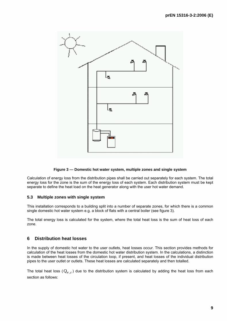
Figure 3 — Domestic hot water system, multiple zones and single system
Calculation of energy loss from the distribution pipes shall be carried out separately for each system. The total energy loss for the zone is the sum of the energy loss of each system. Each distribution system must be kept separate to define the heat load on the heat generator along with the user hot water demand.
5.3 Multiple zones with single system
This installation corresponds to a building split into a number of separate zones, for which there is a common single domestic hot water system e.g. a block of flats with a central boiler (see figure 3).
The total energy loss is calculated for the system, where the total heat loss is the sum of heat loss of each zone.
6 Distribution heat losses
In the supply of domestic hot water to the user outlets, heat losses occur. This section provides methods for calculation of the heat losses from the domestic hot water distribution system. In the calculations, a distinction is made between heat losses of the circulation loop, if present, and heat losses of the individual distribution pipes to the user outlet or outlets. These heat losses are calculated separately and then totalled.
The total heat loss ( dWQ , ) due to the distribution system is calculated by adding the heat loss from each section as follows:

prEN 15316-3-2:2006 (E)
10
col d W i
ind d W d W Q Q Q , , , + = ∑
(1)
where;
inddWQ , heat loss from independent section i of the distribution system
coldWQ , heat loss from circulation loop
Some of the heat losses are recoverable and a proportion of these are recovered. Only the recoverable heat losses are calculated in this standard. The proportion of the heat losses recovered is calculated in prEN15315-1.
Methods are provided for estimating the energy consumed by any auxiliary equipment, e.g. a circulation pump. A proportion of this energy is recovered by the hot water. This is estimated within this standard.
6.1 Distribution pipe heat losses
The domestic hot water distribution pipes cover all piping from the heat generator or hot water storage system to the user outlets, including any circulation loop. The distribution pipes may branch to supply more than one user outlet. Each pipe or pipe section is treated separately. The total heat loss is obtained by adding up heat losses of all the individual pipe sections.
Where there is a circulation loop there are heat losses from the pipes during the whole of the period in which the water is circulating and not only during water draw offs.
Where there is no circulation loop heat losses occur due to the energy used in heating the pipes and fittings of the distribution system. This contributes to a delay in reaching the required minimum temperature of the water at the user outlet. When the desired temperature is reached in the distribution system, heat losses from the distribution system occur during the period of delivery of domestic hot water. The remaining heat energy within the distribution system, after a delivery of domestic hot water, is lost to the surrounding environment, i.e. the heat content of the water in the distribution system and the thermal capacity of the material of the distribution system.
For most uses, a minimum domestic hot water temperature is required at the user outlet before it is considered useful. The energy used to raise the temperature of the water to the minimum required temperature is provided at the user outlet is wasted and considered as a heat loss. In this case the losses from the distribution system are likely to be smaller than the energy lost in the hot water wasted. The heat losses may be reduced if there is a high demand on the distribution system, i.e. a large number of hot water draw-offs occur over a short time period.
Insulation on the distribution pipes reduces the heat loss rate during a hot water draw-off and thus reduces the total heat loss during a hot water demand period. The effect of insulation on the heat loss of the remaining heat energy, in the distribution system after a hot water draw off has been completed, depends on the time periods between each consecutive draw-off. If this time period is short, pipe insulation will reduce the heat loss of the remaining heat energy, as the hot water temperature will not drop to the ambient temperature around the pipe. If this time period is long enough, pipe insulation will not affect the heat loss of the remaining heat energy and the hot water temperature will drop to the ambient temperature around pipe. Depending on the tapping pattern the reduced heat loss and effect of insulation should be taken into account.
This clause describes five methods for calculation of heat losses. The methods differ in the detail of the calculations and the input data required. The method applied can be chosen based on the data available and the objectives of the user. The level of detail chosen should reflect the level of detail used in defining the domestic hot water demand. A National Annex may specify which method should be used for different building types. A national Annex may also specify which method is acceptable for the purpose of energy labelling or any other specific use.
The calculations are based on a daily domestic hot water requirement.

prEN 15316-3-2:2006 (E)
11
6.1.1 Heat emission from pipes based on dwelling area
This method is a simplified method relating the distribution pipe heat loss only to building floor area and thus detailed knowledge of the domestic hot water distribution system is not required. This method can only be applied in a limited number of situations and is usually restricted to domestic buildings with a domestic hot water distribution pipes that does not involve a circulation loop. If this method is applicable, details for the calculation and the limitations in its use shall be given in a National Annex. Although a detailed knowledge of the domestic hot water distribution system is not required, the pipe lengths shall be kept to a minimum. The maximum acceptable distribution pipe length for this method may be given in a National Annex.
6.1.2 Heat emission from pipes based on domestic hot water delivery pipe lengths
Two methods based on pipe length are provided. One method is a simple calculation method while the other method is based on tabulated data. These methods are only suitable for domestic buildings.
6.1.2.1 Simple calculation method
This calculation method takes into account the heat losses from the pipe and the heat losses from the water within the pipe. It is necessary to know the pipe diameters and pipe lengths for each section of the domestic hot water distribution system. It is also possible to include the heat losses from the user outlets in this method. The calculation method is described in Annex A. Details of this method shall be given in a National Annex. A reduction of heat losses in case of short intervals between the tapping cycles is not taken into account in this calculation method. In such a case the effect of pipe insulation on heat losses must be taken into account. If this is to be considered, details shall be given in a National Annex.
This calculation method is applicable only for domestic hot water distribution pipes that do not involve a circulation loop.
6.1.2.2 Tabulated data method
This method is based on estimates of proportion of the heat energy reaching the user outlets for different pipe lengths. A distinction is made between supplies to kitchens and supplies to bathrooms. Detailed knowledge of the domestic hot water distribution system is not required, although an approximation of each of the pipe lengths and pipe diameters is necessary. The proportion of the heat energy reaching the user outlets is tabulated against pipe lengths and diameters. If this method is applicable, details for the calculation and suitable tabulated values shall be given in a National Annex. A table of default values is given in Annex B. This calculation method is applicable only for domestic hot water distribution pipes that do not involve a circulation loop.
6.1.3 Heat emission from pipes based on domestic hot water tapping profiles
This method is based on estimates of the heat losses expressed as a proportion of the domestic hot water energy demand at the user outlet device. Data on domestic hot water energy demand is required for this method. Detailed knowledge of the domestic hot water distribution system is not required as long as sufficient data is available to estimate the average pipe lengths. In addition, data is required on the location of the distribution system, i.e. as to which pipe sections are installed within the heated space and which pipe sections are installed outside the heated space. The calculation method is described in Annex C. Details of this method, including the equivalent energy loss factors, shall be given in a National Annex.
6.1.4 Heat emission from pipes based on a detailed calculation method
If the design of the domestic hot water distribution system is available, a detailed calculation method can be applied.

prEN 15316-3-2:2006 (E)
12
6.1.4.1 Heat energy loss from pipe section
The general determination of heat losses of a pipe section i of a domestic hot water pipe network without a circulatory loop is given by:
WambidWiiidW tLUQ *)(***1000
1,,,, θθ −= (2)
where;
idWQ ,, heat losses of the pipe section (per day), (kW)
iU linear thermal transmission coefficient, (W/mK)
iL length of pipe section (m)
idW ,,θ average temperature of pipe section (oC)
ambθ average ambient temperature (oC)
Wt daily utilisation period at the corresponding temperature, idW ,,θ , (h/day)
The total heat emission from the domestic hot water distribution system is calculated as the sum of heat emissions from the individual pipe sections as follows:
∑=i
idWdW QQ ,,, (3)
The individual components of the equation are obtained from the method given in Annex D.
The heat emission for weekly, monthly or annual time periods can be obtained by multiplying the heat emission for a day by the appropriate number of days.
6.1.4.2 Heat energy lost following domestic hot water delivery
When there are infrequent domestic hot water deliveries during a day then the heat energy within the distribution system, following a hot water draw off, is lost to the surrounding environment. This heat loss is calculated by:
tapambdWWWpdW NVcQ *)(** ,,, θθ −= (W/day) (4)
where
WV volume of water contained in the pipes (m3)
tapN number of hot water deliveries during a day.
The heat energy losses are added to the overall heat losses.
The heat emission for weekly, monthly or annual time periods can be obtained by multiplying the heat emission for a day by the appropriate number of days.
If these losses are to be included then a National Annex will give details of the requirements.

prEN 15316-3-2:2006 (E)
13
6.1.4.3 Heat energy lost due to wasted water
Heat energy is lost if a minimum water temperature is required before the domestic hot water can be used. If the hot water demand is defined in pr EN15316-3-1 on the basis of tapping cycles then the conditions for the minimum hot water temperatures and flow rates will be defined.
If the hot water performance of the generator unit is measured in accordance with EN13203-2 then the energy of the wasted hot water will be measured.
If the generator performance has not been measured according to EN13203-2 then the wasted hot water may be calculated. A National Annex will give details of the method and the assumptions to be made.
6.2 Heat emission from circulation pipes
This section describes methods for estimating the energy loss from hot water circulation pipes.
6.2.1 Heat emission from circulation loop based on pipe length
A fixed value of heat loss from the circulation loop may be assumed. This method is applicable if exact design of the domestic hot water system is not available or the pipe insulation thickness is not known. Values should be given in a National Annex. If a National Annex is not provided or does not include this value, a default value is given in Annex E.
6.2.2 Heat emission from circulation loop based on a calculation method
A detailed calculation method may be applied for the circulation loop. The calculation method is the same as described for pipe sections in 5.1. The method is detailed in Annex E. The effect of periods when there is no circulation is dealt with in paragraph 5.2.3.
6.2.3 Additional heat emission from circulation loop during periods of no circulation
If the circulation loop is not operated continuously, the heat energy within the circulation loop is lost to the surrounding environment. This heat loss is calculated by:
NormAmbdWWWoffdW NVcQ ∗−∗∗= )( ,,, θθ (5)
where
WV volume of water contained in the pipes (m3)
NormN number of circulation pump operating cycles during a day.
The heat losses during periods of no circulation are added to the overall heat losses.
Losses from the branching pipes to user outlets during times of no circulation are accounted for in the heat loss calculations for those pipes.
The heat emission for weekly, monthly or annual time periods can be obtained by multiplying the heat emission for a day by the appropriate number of days.
6.2.4 Heat emission due to accessories
The heat emission from the circulation loop is increased by the energy lost through fittings i.e. valves and flanges and also through pipe hangers.
These heat emission values are estimated by introducing an additional equivalent pipe length. If these losses are to be included in the analysis then details will be given in a National Annex.

prEN 15316-3-2:2006 (E)
14
6.3 Distribution pipe heat losses from a collective domestic hot water distribution system
A collective domestic hot water distribution system is a system supplying a number of individual single family households. Each household has a hot water system analogous to that in a single family dwelling. The household hot water systems are fed by a single continuous or programmed circulation of domestic hot water in a closed loop in order to maintain a preset domestic hot water temperature. Circulation of the water is achieved by means of a circulation pump. It is applicable to calculate the heat losses from the circulation loop by the detailed calculation method and use one of the other methods for calculation of the heat losses from the branching pipes to the user outlets.
The total heat loss ( dWQ , ) due to the distribution system is calculated by adding the heat loss from each section as follows:
col d W i
ind d W d W Q Q Q , , , + = ∑
(6)
where;
inddWQ , heat loss from independent section i of the distribution system
coldWQ , heat loss from collective circuit
6.4 User outlets
The domestic hot water is supplied to the user through a user outlet, e.g. a tap, showerhead or similar device. Depending on the design and the material of construction, the user outlet will absorb heat energy during the supply of hot water and cause a delay in reaching the required minimum hot water temperature at the user outlet. This delay increases heat losses in the domestic hot water distribution system.
The additional energy lost in the wasted hot water may be combined with the losses due to the distribution system. No additional calculation is then necessary to take user outlets into account.
If the losses from the user outlets are to be considered separately, the need for this calculation shall be indicated in a National Annex. The basis of the calculation method is given in Annex E. These losses are dependent on the number of hot water draw offs. This dependence shall be detailed in the National Annex.
Default values for the heat loss from different types of user outlets may be used in place of a calculation. If default values are applicable, these shall be given in a National Annex.
7 Auxiliary energy
Auxiliary energy may be used for ribbon heating and for pumps.
7.1 Auxiliary energy used for ribbon heating
Where ribbon heating or trace heating is applied to reduce the heat losses, it is assumed that the energy consumption of the ribbon heater is equal to what the heat losses from the pipe would have been without the heater. The ribbon heater does not contribute to the generation of hot water. The heat losses compensated by the ribbon heater shall not be added to the heat losses of other individual parts of the domestic hot water distribution system used to determine the heat demand and the load on the generator. The ribbon heater is supplied by electricity and should thus be considered as part of the auxiliary energy requirements.
prEN 15316-3-2:2006 (E)
15
The auxiliary electrical energy required for the ribbon heater is calculated by:
WAmbdWdWribidW tULQ ∗−∗∗= )( ,,,, θθ (Wh) (7)
where
ribiL , length of pipe heated by trace heating (m)
dWU , heat loss coefficient of pipe (W/mK)
dW ,θ average temperature of pipe section (oC)
Ambθ average ambient temperature (oC)
Wt duration of the provision of hot water (h/day)
It is assumed that the ribbon heater operates during the same time periods as the domestic hot water heating programme setting if this is not continuous.
The heat emission for weekly, monthly or annual time periods can be obtained by multiplying the heat emission for a day by the appropriate number of days.
7.2 Auxiliary energy used for pumps
A pump is required for a circulation loop and in some cases a boost pump may be used in order to increase the water pressure from a low pressure cold water supply. A boost pump may be installed at the inlet of the system, increasing the pressure at all the domestic hot water user outlets, or it may be fitted at a single delivery point, e.g. a shower.
Electrical energy is required for the pump to overcome the hydraulic losses within the domestic hot water distribution system. A simplified method or a detailed calculation method may be applied to estimate the energy used by pumps in domestic hot water systems.
The proportion of the electrical energy used by a pump, which is transferred as heat into the circulating water, will be provided by a National Annex. If there is no National Annex or a value is not provided then the default value given in Annex F may be used.
7.2.1 Simplified method
The auxiliary electrical energy required for the pump may be estimated from the pump power rating as follows:
pumppumppumpWd PfW *, = (8)
where
pumpWdW , electrical energy requirement (kWh/day)
pumpf pump running time (hours/day)
pumpP power rating of the pump (kW)

prEN 15316-3-2:2006 (E)
16
Values for pumpf should be given in a National Annex. If a National Annex is not provided or does not include this value, a default value is given in Annex G.
The auxiliary electrical energy required for weekly, monthly or annual time periods can be obtained by multiplying the auxiliary electrical energy for a day by the appropriate number of days.
7.2.2 Detailed calculation method
If the design of the domestic hot water distribution system is available, a detailed calculation method can be applied. The electrical energy required for the pump can be calculated from the hydraulic energy requirement and the performance of the pump.
The general calculation of the energy required for the circulation pump is:
WdhydrWdpumpWd eWW ∗= ,, (9)
where
pumpWdW , electrical energy requirement (kWh/day)
hydrWdW , hydraulic energy requirement (kWh/day)
Wde performance coefficient for circulation pump
Details of the method are given in Annex F. The auxiliary electrical energy required for weekly, monthly or annual time periods can be obtained by multiplying the auxiliary electrical energy for a day by the appropriate number of days.
8 Recoverable, recovered and unrecoverable heat losses
The calculated heat losses are not all necessarily lost. Some of the heat losses can be recovered and contribute to the space heating. Only part of the recoverable losses will be useful, however, as recoverable losses can only be considered during periods of the year where there is a significant space heating demand. Under some circumstances, the recoverable heat losses may add to the cooling load required in a building.
The recoverable losses are determined by the location of the pipe. If the pipe is installed in the heated part of the building, the losses may be recoverable. The proportion of the total recoverable losses that can be recovered is determined in pr EN15315-1, for which the total recoverable losses are provided as an input.
In some situations the overall heat energy losses may be reduced by an energy gain from the building to the cold water supply or by heat recovery from the wastewater. These energy transfers may be ignored unless required by a National Annex.
Some of the auxiliary energy may be recovered as heat in the domestic hot water system, e.g. some electrical energy supplied to the circulation pump ends up as thermal energy in the water. The recovered heat losses from the circulation pump transmitted to the water is taken into account directly in the distribution sub-system as a reduction of the heat losses. The proportion of the pump energy to be considered as recovered will be detailed in a National Annex. If a value is not given then this energy is not considered in the calculation. For the purpose of the calculations, the energy recovered is subtracted from the circulation loop pipe loss.

prEN 15316-3-2:2006 (E)
17
Annex A (informative)
Calculation of heat emission from pipes based on domestic hot water
delivery pipe lengths – simple calculation method
This calculation method takes into account the heat losses from the pipe and the heat losses from the water within the pipe. It is necessary to know the pipe diameters and pipe lengths for each section of the domestic hot water distribution system.
For every pipe section i the maximum losses are given by:
tapiinomWjMmpiWWpWidW nTTMCVCQ *}{*}***{ int,,,,,,,,, −+= ρ (J/day) (A1)
where:
Wρ specific mass of water (kg/m3)
PWC specific heat of water (J/kg.K)
iWV , volume of water contained in pipe i (m3)
PMC specific heat of pipe material (J/kg.K)
iMM , mass of pipe i (kg)
inomWT ,, nominal hot water temperature in pipe i (°C)
iTint, average internal temperature around pipe i (°C)
tapn number of tappings per day using pipe section i (-)
Hot water losses at the user outlets, while the desired domestic hot water temperature has not been reached, are not included in this calculation method.
If the heat losses from user outlets, i.e. materials of shower heads or taps, are to be included, a further contribution is added to equation A1 taking into account the mass and specific heat of the user outlet material.
This calculation method is only applicable for domestic hot water distribution pipes that do not involve circulation loop.

prEN 15316-3-2:2006 (E)
18
Annex B (informative)
Calculation of heat emission from pipes based on domestic hot water
delivery pipe lengths – tabulated data method
This method is only suitable for domestic buildings with water distribution pipes that do not include a circulation loop. It is based on estimates of the proportion of the heat energy reaching the user outlets for different pipe lengths. A distinction is made between supplies to kitchens and supplies to bathrooms.
It is necessary initially to determine the length of the delivery pipes from the heat generator (or hot water storage vessel) or from the circulation loop to the kitchen and to the bathroom: Lkitchen and Lbathroom.
The proportion of heat energy reaching the user outlet is termed:
kitchentube,η and bathroomtube,η , respectively.
Values for these parameters are to be obtained from tables. Default values are given in Table B.1.
The combined efficiency of the domestic hot water delivery pipes is calculated by:
ηpipe = 1 / (fkitchen/ηpipe;kitchen + fbath/ηpipee;bath) (B1)
where;
kitchenf fraction of hot water demand in the kitchen
bathroomf fraction of hot water demand in the bathroom
Default values for kitchenf and bathroomf are:
2 . 0 = kitchen f
8 . 0 = bathroom f
The total heat loss from the domestic hot water delivery pipes is calculated by:
Qwd;p = Qw * (1 - ηpipe ) / ηpipe (B2)
where;
Qwd;p heat loss of delivery pipes
Qw hot water demand

prEN 15316-3-2:2006 (E)
19
Table B1 : Proportion of heat reaching user outlets
Lxxx [m] <2 2-4 4-6 6-8 8-10 10-12 12-14 >14
Kitchen ηpipe;kitchen
dint < 8mm for 2/3 of the pipe length
1.00 0.86 0.75 0.67 0.60 0.55 0.50 0.46
dint < 10mm for 2/3 of the pipe length
1.00 0.79 0.65 0.55 0.48 0.43 0.38 0.35
Other pipes 1.00 0.69 0.53 0.43 0.36 0.31 0.27 0.24
Bathroom ηpipe;bath
All pipes 1.00 0.95 0.90 0.86 0.82 0.78 0.75 0.72
NOTE: These values are determined assuming: - an average of 2 tappings of 1 litre in the kitchen and tapping of 8 litres in the bathroom for every 10 litres; - complete loss of the heat energy of the water content in the pipes; - additional loss of the heat energy of the water content in the pipes and start/stop losses, at a rate of 0.7 of
the loss of the heat energy of the water content in the pipe.

prEN 15316-3-2:2006 (E)
20
Wd Q
Annex C (informative)
Calculation of heat emission from pipes based on domestic hot water
tapping profiles
This method is based on estimates of the heat losses expressed as a proportion of the domestic hot water energy demand at the user outlet device. Data on domestic hot water energy demand is required for this method. If heat losses from user outlets are taken into account, these losses should be added to the domestic hot water heat energy requirement for determination of the domestic hot water energy demand.
The domestic hot water energy demand is based on the European domestic hot water tapping cycles. Although these will not be identical to the domestic hot water energy usage for all potential building and usage types, they do provide a representative mixture of small and large hot water draw-offs for different total energy requirements.
The heat loss is expressed as:
W Wd Wd Q Q ∗ = α (C1)
where;
Wdα energy loss factor as proportion of the hot water energy requirement
W Q domestic hot water energy demand
Three values of Wdα are required based on each of the three hot water tapping cycles:
1Wdα energy loss factor for hot water tapping cycle 1, equivalent to 2100 Wh/day,
2Wdα energy loss factor for hot water tapping cycle 2, equivalent to 5845 Wh/day,
3Wdα energy loss factor for hot water tapping cycle 3, equivalent to 11655 Wh/day
then
111 WWdWd QQ ∗=α
222 WWdWd QQ ∗=α
333 WWdWd QQ ∗=α
nhsaveWd LL ∗+−∗+= 008.0)6(005.009.01α
nhsaveWd LL ∗+−∗+= 008.0)6(005.010.02α

prEN 15316-3-2:2006 (E)
21
nhsaveWd LL ∗+−∗+= 008.0)6(005.005.03α
where;
aveL average length of distribution pipe within heated space
nhsL average length of distribution pipe in non heated space (if appropriate)
For a specific level of domestic hot water energy demand, an interpolation can be applied:
If 2WW QQ < )](/)[(01.0 1222 WWWWWdWd QQQQ −−∗−=αα
If 2WW QQ > )](/)[(05.0 2322 WWWWWdWd QQQQ −−∗−=αα
Two higher European tapping cycles have been developed for larger domestic hot water demands. These may also be applied if the actual domestic hot water energy demand is higher than 3WQ .

prEN 15316-3-2:2006 (E)
22
Annex D (informative)
Calculation of heat emission from domestic hot water pipes
D.1 Calculation of heat emission based on pipe length
Where a National Annex is not provided or a value for the heat emission is not given then a default value of 40W/m of pipe length may be used.
D.2 Heat emission from pipes based on a detailed calculation method
The variables required for calculating the heat emission from pipes can be obtained by the following.
D.2.1 Determining length of pipe sections
For carrying out the calculations, the domestic hot water distribution system may be considered as occurring in up to three different zones. In general, these zones can be described as the horizontal distribution from the heat generator to the main supply pipes (zone LV), the main supply pipes (zone LS) and the individual branching pipes to the user outlets (zone LSL).
Figure D1 — Location of pipes

prEN 15316-3-2:2006 (E)
23
The pipes within zone LV (see Figure D.1) may lie within an unheated space such as a cellar or an attic. They may also lie within a thermal skin of the building or the floor. The pipes within zone LS may be vertical or horizontal or a combination of both. They will normally lie within the thermal skin of the building. In specific installations not all of these zones may be present.
Pipes within zones LV and LS may involve a circulation loop. These are treated separately. Pipes within zone LSL will not involve a circulation loop
For new buildings with already designed domestic hot water system and also for new domestic hot water systems installed in existing buildings, only designed or actually installed lengths of pipe sections should be considered for further calculations of heat emission. However, representative values of pipe lengths can be used for new buildings in the early stage of design when the exact design of domestic hot water system is still not available. These values are related to the effective floor area of the building, default values given in Table D.1 may be applied. These default values are based on an average floor area of 80 m2 and an average pipe spur length of 6 m.
Table D.1 : Characteristic values for use in calculation of heat loss from circulation loop and distribution pipes
Parameters Symbol Unit V region S region SL region
Ambient temperature outside the heating period ϑi °C 22 °C
Ambient temperature ϑi °C
13°C in the unheated region and 20°C in the heated region
20°C in the heated region
Length of circulating loop L m 2·LG+ 0.0125·LG·BG
0.075·LG·BG·nG·hG —
Length of main distribution pipe L m LG+
0.0625·LG·BG 0.038·LG·BG·
nG·hG —
Individual branch pipe length only for transfer into adjacent rooms with a common installation wall
L m — — 0.05*LG*BG *nG
Individual branch pipe length in all other cases L m — — 0.075*LG*BG*nG
Where:
LG is the largest extended length of the building (m)
BG is the largest extended width of the building (m)
nG is the number of heated storeys
hG is the height of the storeys (m)
The length of the individual pipes is to be determined directly. If no detailed pipe network plan is available, the length can be determined from Table D.2 according to the number of tap points per domestic hot water branch connected. The assumption is made that the individual branch pipes are always laid in the heated region.

prEN 15316-3-2:2006 (E)
24
Table D.2 : Characteristic values for calculation of heat loss in individual hot water supply pipes
Parameter Symbol Unit SL zone
Average ambient temperature θ Amb C 20
Pipe length for one tap in a room, e.g. from under-sink heater to tap
L m ⎟⎠⎞
⎜⎝⎛∗
801 NA
Pipe length for more than one tap in a room, e.g. in a bathroom
L m ⎟⎠⎞
⎜⎝⎛∗
803 NA
Pipe length for more than one tap in adjacent room with a common installation wall
L m ⎟⎠⎞
⎜⎝⎛∗
804 NA
Pipe length for supply central within the home unit
L m ⎟⎠⎞
⎜⎝⎛∗
806 NA
Decentralised domestic hot water systems provide individual rooms with hot water and therefore have no central distribution system or circulation loops. In this case the only losses from the distribution system are associated with pipes forming individual distribution pipes. The heat generator may supply a single user outlet or a number of user outlets. In either case the heat generator will be installed within the heated space of the building and hence there will be no distribution pipes in an unheated space. For calculation of the heat loss from these pipes, the actual length of the pipes should be used. If details of the piping are not available, representative values for the pipe lengths can be used. These values are related to the floor area of the building and may be given in a National Annex. If a National Annex is not provided or does not include these values, default values given in Table D.2 may be applied.
D.2.2 Determining heat transfer coefficients
The heat transfer coefficient for any pipe section depends on the diameter of the pipe, the location of the pipe (whether in the heated area or not), the type and thickness of any insulation and the age of the installation.
Local or National requirements may define the level of pipe insulation to be used, and thus determine the heat transfer coefficients. Values for insulated pipes may therefore be given in a National Annex. If a National Annex is not provided or does not include these values, default values given in Table D.3 may be applied.
D.2.2.1 Un-insulated pipes exposed
The heat emission from an un-insulated pipe consists of losses through both convection and radiation. The heat transfer from the hot water to the pipe wall and the conduction within the pipe wall (for metal pipes) can be ignored. Where these pipes are exposed, the resulting heat loss coefficient is given in Table D.3.
D.2.2.2 Un-insulated pipes beneath plaster
For un-insulated pipes installed under plaster, a distinction is made between
⎯ pipes in an un-insulated outer wall of an older building;

prEN 15316-3-2:2006 (E)
25
⎯ pipes in an external wall insulated on the outside in an older or new building;
⎯ pipes in a single layer external wall in a new building.
D.2.2.3 Insulated pipes
The heat loss coefficient can be calculated by:
AAR
AR
ddd
U
∗+
=
αλ
π1ln
21
(W/m.K) (D1)
where
λ heat conductivity of the insulation (W/m.K)
Ad external diameter of insulated pipe (including insulation) (m)
Rd pipe diameter (m)
Aα heat transfer coefficient (W/m2K)
value for insulated pipes = 8 W/m2K
value for uninsulated pipes = 14 W/m2K
If the information is not available to calculate the heat loss coefficients then the values given in Table D.3 may be used.
Table D.3 — Thermal transmission coefficients Ui in W/(m · K)
Distribution Externally lying pipes Internally lying pipes Age class of building
V S SL S SL
From 1995 0.200 0.255 0.255 0.255 0.255
1980 to 1995 0.200 0.400 0.400 0.300 0.400
Up to 1980 0.400 0.400 0.400 0.400 0.400
Non-insulated pipework
LG BG ≤ 200 m² 1.000 1.000 1.000 1.000 1.000
LG . BG ≤ 500 m² 2.000 2.000 2.000 2.000 2.000
LG . BG > 500 m² 3.000 3.000 3.000 3.000 3.000
Laid in external wall total/usable
External wall non-insulated 1.35 / 0.80
External wall externally insulated 1.00 / 0.90
External wall (U = 0.4 W/m² · K) 0.75 / 0.55

prEN 15316-3-2:2006 (E)
26
D.2.3 Tabulated method for calculating heat loss coefficient
An alternative simplified method for calculation of the heat loss coefficient may be applied. The simplified equation for the heat loss coefficient is:
dUWRdUWdW BdAU ,,, +∗= (W/m.K) (D2)
where:
coefficients dUWA , and dUWB , may be given in a National Annex. If a National Annex is not provided or does not include these values, default values given in Table D.4 may be applied.
Table D.4 : Parameters for calculation of the heat emission coefficient of pipes
Type of pipe insulation dR min. dR max. AUd,w BUd,w
Class 2 10 300 2.60 0.200
Class 3 10 300 2.00 0.180
Class 4 10 300 1.50 0.160
Class 5 10 300 1.10 0.140
Class 6 10 300 8.00 0.120
D.2.4 Determining average ambient temperature
The ambient temperature is solely dependent on the location of the pipe.
)( int,int extdWAmb b θθθθ −∗−= (oC) (D3)
where:
intθ internal temperature (oC)
extθ mean outside temperature (oC)
dWb , location factor
Values for the location factor are given in Table D.5.
Table D.5 : Factor corresponding to the location of the pipes
Location of the circulation loop bWd
Outside the building 1
Outside the heated volume, horizontal circulation 0.8
Within heated volume 0
Other (e.g. embedded pipe) to be calculated and substantiated

prEN 15316-3-2:2006 (E)
27
D.2.5 Determining average temperature of pipe section
The average domestic hot water temperature within a pipe section may be given in a National Annex. If a National Annex is not provided or does not include this value, the default average temperature for the water in an individual spur is taken as 32oC and the default average temperature for the water in a circulation loop is taken as 60oC.
Table D.4 : Factor corresponding to the location of the pipes
Location of the circulation loop bWd
Outside the building 1
Outside the heated volume, horizontal circulation 0.8
Heated volume 0
Other (e.g. embedded pipe) to be calculated and substantiated

prEN 15316-3-2:2006 (E)
28
Annex E (informative)
Calculation of heat loss from user outlets
If heat losses associated with the thermal capacity of the user outlets are to be taken into account, the effect of different outlet types may be calculated from the following procedure.
The heat loss due to the user outlets is:
temeem nnQ *∗= β (E1)
where
emβ heat loss of the specific type of user outlet (Wh)
emn number of user outlets in the building
nt number of tapping cycles during the period considered
If this calculation is considered necessary, values for emβ and nt shall be provided in a National Annex.
emβ depends on the domestic hot water temperature, the cold water inlet temperature and the water flow rate, and should be determined based on the values in Table E.1.
Table E.1 : Basic conditions for determination of emβ
Domestic hot water temperature 60 °C
Cold water inlet temperature 10 °C
Water flow rate 12 l/ min
The number of tapping cycles during the period considered, nt , depends on the type of activity.
prEN 15316-3-2:2006 (E)
29
Annex F (informative)
Calculation of energy requirement of a circulation pump
F.1 Simplified method for calculating energy requirement of a circulating pump
If the simplified calculation method is used to estimate the auxiliary pump energy the default value 8760=pumpf may be applied (this is the worst case situation, assuming the pump operates continuously).
F.2 Detailed method for calculating energy requirement of a circulating pump
If the detailed calculation method is used then:
F.2.1 Hydraulic energy requirement
The hydraulic energy depends on the hydraulic resistance of the system and the pump running time.
WhydrhydrdW tPW *,, = (kWh/day) (F1)
where
hydrP hydraulic power required by the pump (kW)
Wt duration of the provision of domestic hot water (h/day)
F.2.2 Hydraulic power required of the pump
The hydraulic power required by the circulation pump to overcome the hydraulic resistance of system is:
VpPhydr&∗Δ∗= 2778.0 (kW) (F2)
where
V& volume flow rate (m³/h)
pΔ differential pressure across the pump (kPa)
The volume flow rate depends on the thermal output of the heat generator, DQ& , and the maximum
temperature difference, ZϑΔ , across the heat generator:
Z
DQVϑΔ∗
=15.1
&& (m³/h) (F3)

prEN 15316-3-2:2006 (E)
30
The differential pressure across the circulation pump depends on the resistance of the pipes and fittings in the circulation system as follows:
AppTHRV ppLp Δ+Δ+∗=Δ ∑ ,max1.0 (kPa) (F4)
where
maxL maximum pipe length (m)
THRVp ,Δ differential pressure across fittings, such as back flow preventer and thermostatic valve (kPa)
ApppΔ differential pressure across heat generator (kPa)
If no product data are available, the following standard vales are to be used:
• for storage tanks 1 kPa;
• for continuous-flow systems 15 kPa
The maximum pipe length for the circulation pipework can for a rectangular building approximately be determined from the external dimensions of the building/zone.
( )GGGmax 5,22 hnLL ⋅++⋅= (F5)
where
LG is the largest extended length of the building (m)
nG is the number of heated storeys
hG is the average height of a storey (m)
F.2.3 Duration of the provision of domestic hot water
The running time of the circulation path is determined for apartment blocks by:
GGGG32,05007,0
110
hnBL
z
⋅⋅⋅⋅+
+= (F6)
where
LG is the largest extended length of the building (m)
BG is the largest extended width of the building (m)
Gn is the number of heated storeys
Gh is the average height of a storey (m)
Here care must be taken that Wt is not greater than 24 hours.
For non-residential buildings Wt is to be set equal to the daily utilisation time period tNutz .

prEN 15316-3-2:2006 (E)
31
F.2.4 Pump performance coefficient
The performance coefficient for operation of the circulation pump is:
94.0
,−∗∗= DPeed Cfe β (F7)
where
ef efficiency factor
PC pump control factor according to Table F1
Dβ load factor
If power rating of the circulation pump is given, the efficiency factor, ef , is calculated by:
hydr
Pumpe P
Pf = (F8)
where pumpP is the power rating of the circulation pump (kW).
If power rating of the circulation pump is not available, the efficiency factor, ef , is given by:
04.0015.05.1
74.0 +∗∗
=hydr
e Pbf (F9)
where b = 1 for new buildings and b = 2 for existing buildings.
Table F.1 : Pump control factor pC
Pump control fixed speed constpΔ varpΔ
pC 0,97 0,66 0,52
The load factor, Dβ , is the ratio of the actual circulated flow divided by the maximum circulated flow. If there is
no flow controller applied, 1=Dβ .
In an existing building, power rating of the circulation pump may be available from the pump data plate. The specific power rating should be used for the calculations if available. If details of the piping and/or pump specification are not available, representative values or a simplified calculation method may be applied.

prEN 15316-3-2:2006 (E)
32
F.2.5 Intermittent pump operation
If domestic hot water is not required for a full 24-hour period per day, the circulation pump may be operated at an intermittent basis. For convenience, this may be considered as continuous normal operation during daytime and continuous operation at minimum load during nighttime. The energy required for the circulation pump in this case is:
( )nightdayedhydrded eWW αα ∗+∗∗= 6.0,,, (kWh/day) (F10)
where
day α ratio of circulation pump running hours at normal operation to total running hours
night α ratio of circulation pump running hours at minimum load to total running hours
night day α α + = 1.0
If the circulation pump is shut off during nighttime, nightα = 0 and dayα = 1.0 . (The total running hours of
the circulation pump is taken into account by running time parameter Wt in equation F1.)
F.2.6 Expenditure value coefficient
For evaluation of the operating characteristic of the circulation pump an expenditure value coefficient ew,d,aux is:
( )p2p1auxd,w, CCfe +⋅= e (F11)
where
Cp1 and Cp2 are the constants from Table F2.
fe is the efficiency factor according to the following definition:
bP
f ⋅⎟⎟
⎠
⎞
⎜⎜
⎝
⎛
⎟⎟⎠
⎞⎜⎜⎝
⎛+=
5.0
hydre
20025.1 for an unidentified pump
hydr
Pe P
Pf = for an identified pump
where
b is the over-dimensioning factor, which is determined as follows:
⎯ for pumps, which are designed to the demand, b = 1;
⎯ for pumps, which are not designed to the demand, b = 2.
For existing pumps the relevant performance data on the type plate of the pump can be taken as an approximation for PP.

prEN 15316-3-2:2006 (E)
33
Table F.2 — Constants Cp1, Cp2 for the calculation of the expenditure value coefficient of circulation pumps
Pump control Cp1 Cp2
Unregulated 0.25 0.94
Regulated 0.50 0.63
F.3 Energy recoverable factor
A proportion of the energy supplied to the pump may be recovered as heat to the circulating water. If no value is provided then a default value of 80% of pumpWdW , may be used. This energy should be subtracted from the energy loss from the circulating loop.