Embed Size (px)
Citation preview
Revision 4 March 29, 2016
Individual chapters of the Kalsi Seals Handbook are periodically updated. To determine if
a newer revision of this chapter exists, please visit www.kalsi.com/seal-handbook.htm.
NOTICE: The information in this chapter is provided under the terms and conditions of the Offer of
Sale, Disclaimer, and other notices provided in the front matter of this handbook.
Document 3079 © 2016 Kalsi Engineering, Inc. All rights reserved.
Kalsi Seals Handbook
Chapter D8
Heat transfer considerations
Heat transfer considerations Chapter D8 Page 1
Contact Kalsi Engineering Search this handbook
1. Introduction
The dynamic sealing interface of a Kalsi Seal is relatively wide, to provide strength
for resisting high differential pressure, and to provide sacrificial material to accomodate
axially acting wear mechanisms. Lubricant shearing action and minor asperity contact
within this interface causes a Kalsi Seal to generate heat during rotation, and the seal
becomes hotter than the environment. This is true of all Kalsi Seals, although some types
(such as Hybrid and Enhanced Lubrication seals) run significantly cooler than others.
Increased rotary speed affects interfacial film viscosity, thickness and viscous shearing
action, and increases seal generated heat. The heat increase is not proportional to the
increase in speed; instead, the seal generated heat increases at a rate that is greater than the
increase in speed. Elevated temperature increases various seal degradation mechanisms,
such as compression set, extrusion damage, and media absorption.
Plan to provide adequate heat transfer
Seal generated heat is significant in many applications, and an efficient heat transfer
arrangement typically is necessary to prevent overheating. Even though Kalsi Seals are
hydrodynamically lubricated, they do not alter the basic laws of thermodynamics. Failure
to provide adequate heat dissipation can result in rapid seal overheating and destruction.
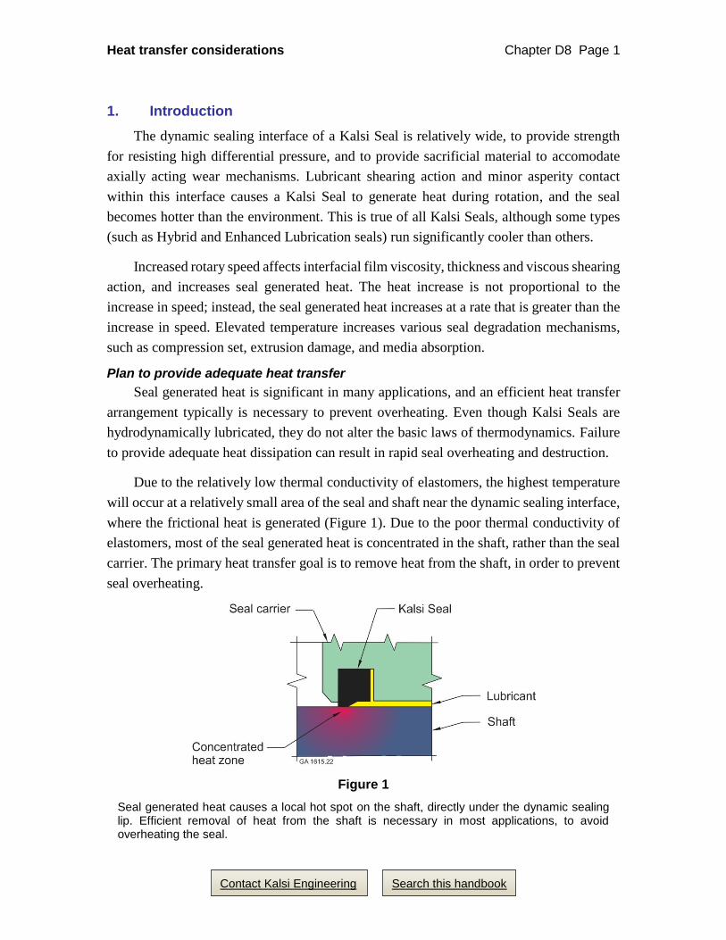
Due to the relatively low thermal conductivity of elastomers, the highest temperature
will occur at a relatively small area of the seal and shaft near the dynamic sealing interface,
where the frictional heat is generated (Figure 1). Due to the poor thermal conductivity of
elastomers, most of the seal generated heat is concentrated in the shaft, rather than the seal
carrier. The primary heat transfer goal is to remove heat from the shaft, in order to prevent
seal overheating.
Figure 1
Seal generated heat causes a local hot spot on the shaft, directly under the dynamic sealing lip. Efficient removal of heat from the shaft is necessary in most applications, to avoid overheating the seal.
Heat transfer considerations Chapter D8 Page 2
Contact Kalsi Engineering Search this handbook
2. How much cooling do I need?
We are often asked questions like, “How fast can I rotate without active cooling?” or,
“Is the heat transfer of this design adequate?” The truthful answer to most of these
questions is “We can’t do thermal finite element analysis in our heads; nobody can.” The
heat transfer situation and operating conditions of each application are unique. The most
appropriate answers to such questions rely on:
Thermal finite element analysis using conservative seal torque values to
predict seal generated heat, or
Testing of the actual hardware using actual operating conditions.
When evaluating applications, it is important to consider the temperature at the rotary
seal, rather than the bulk temperature of the environment. Kalsi Engineering can assist in
heat transfer evaluation by providing testing and thermal finite element analysis on a
consulting basis, depending on staff availability.
Calculating seal power consumption for thermal finite analysis
Horsepower is determined by multiplying running torque in foot pounds times rotary
speed in rpm, and dividing by 5252. Use published factors to convert horsepower to any
other desired power unit, such as kilowatts. Kalsi Seal torque is typically reported in inch
pounds. To convert inch pounds to foot pounds, divide by 12. To convert the torque of a
given diameter seal to another diameter, use Equation 1, below.
Equation 1, Conversion of test torque to other sizes:
TS = (S/ST)2 x TT
Where:
S = Shaft diameter
ST = Shaft diameter of the test rotary seal
TS = Predicted torque for a seal diameter of S
TT = Torque of a seal diameter of ST
For example, if the running torque of a 2.75” (69.85 mm) seal is 40 in-lb (4.52 N·m),
the torque for a 5.50” (139.7 mm) seal would be 160 in-lb (18.08 N·m), using Equation 1:
TS = (5.50”/2.75”)2 x 40 in-lb = 160 in-lb
or
TS = (139.7 mm/69.85 mm)2 x 4.52 N·m = 18.08 N·m
Heat transfer considerations Chapter D8 Page 3
Contact Kalsi Engineering Search this handbook
3. Cooling circulation through a hollow shaft
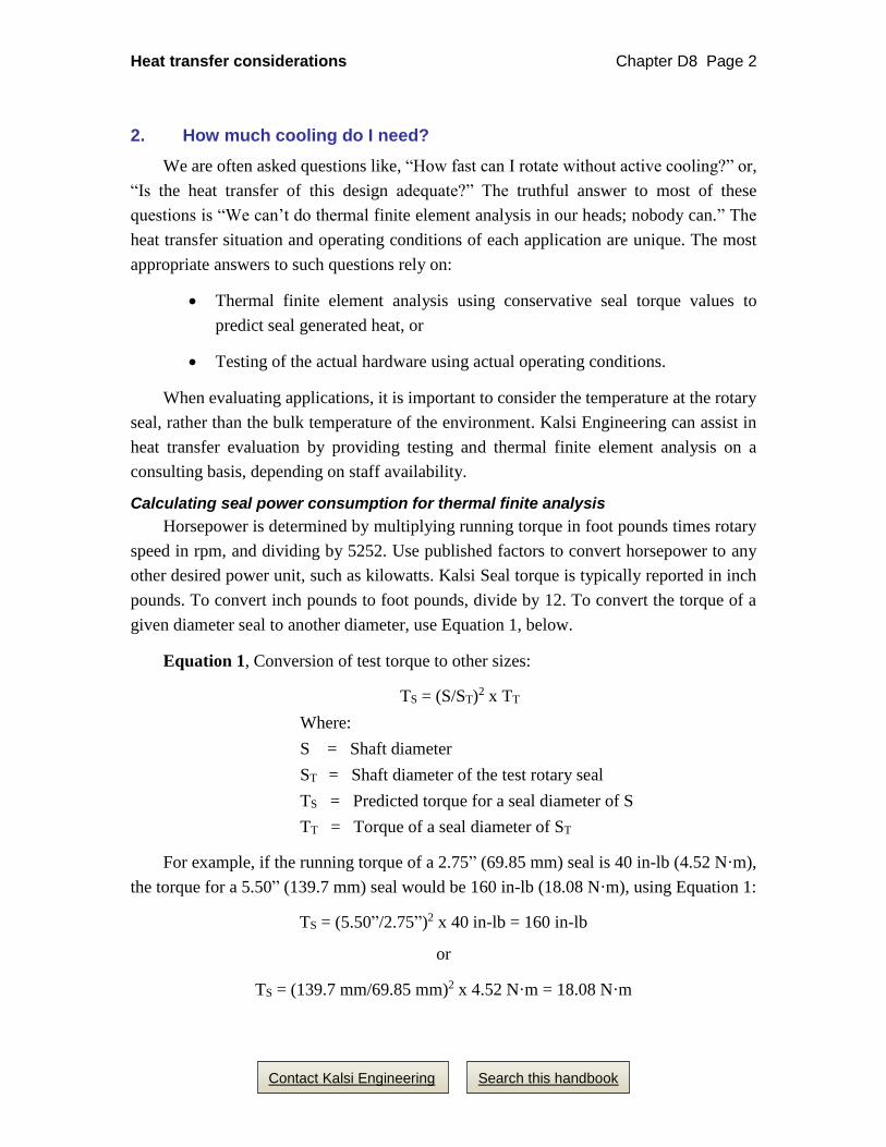
In applications where fluid circulates through the shaft during shaft rotation, the
circulation removes seal generated heat from the shaft (Figure 2). This can be a very
effective cooling method, provided the groove bore has adequate roughening (Chapter D5)
to prevent circumferential seal slippage at the OD of the seal. (If excessive circumferential
seal slippage occurs, then the flow through the shaft may not cool the seal carrier
adequately.)
Figure 2
Cooling flow through a hollow shaft
Circulating fluid through the shaft bore can effectively extract seal generated heat from the shaft, provided that excessive circumferential slippage of the seal at its OD is prevented. Such slippage generates heat at a location not efficiently cooled by the circulating fluid within the shaft. One method for inhibiting circumferential slippage at the seal OD is the grit blasting technique described in Chapter D5 of this rotary seal handbook.
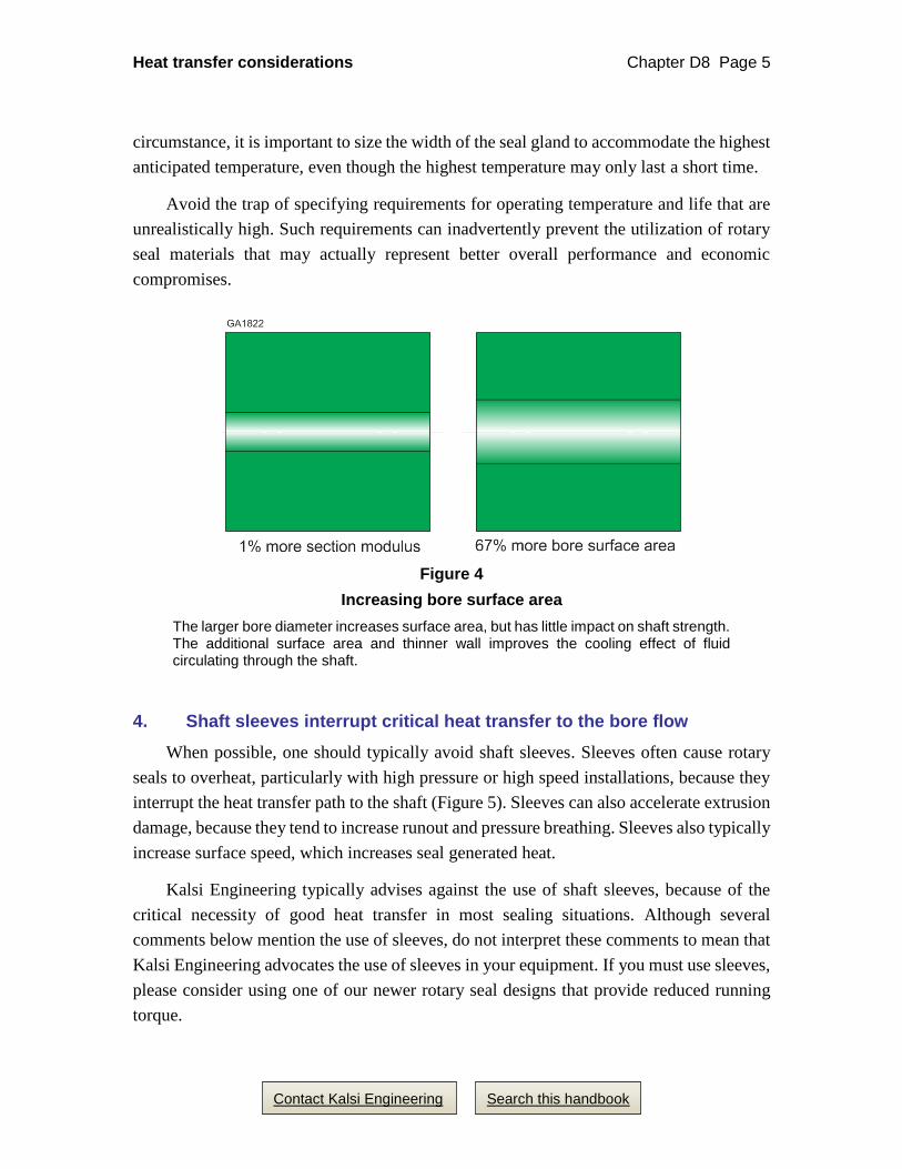
Avoiding small shaft bores is a good way to improve the cooling effect achieved by
circulating fluid through the shaft. Larger bores improve heat transfer while sacrificing
little in shaft bending strength (Figure 4).
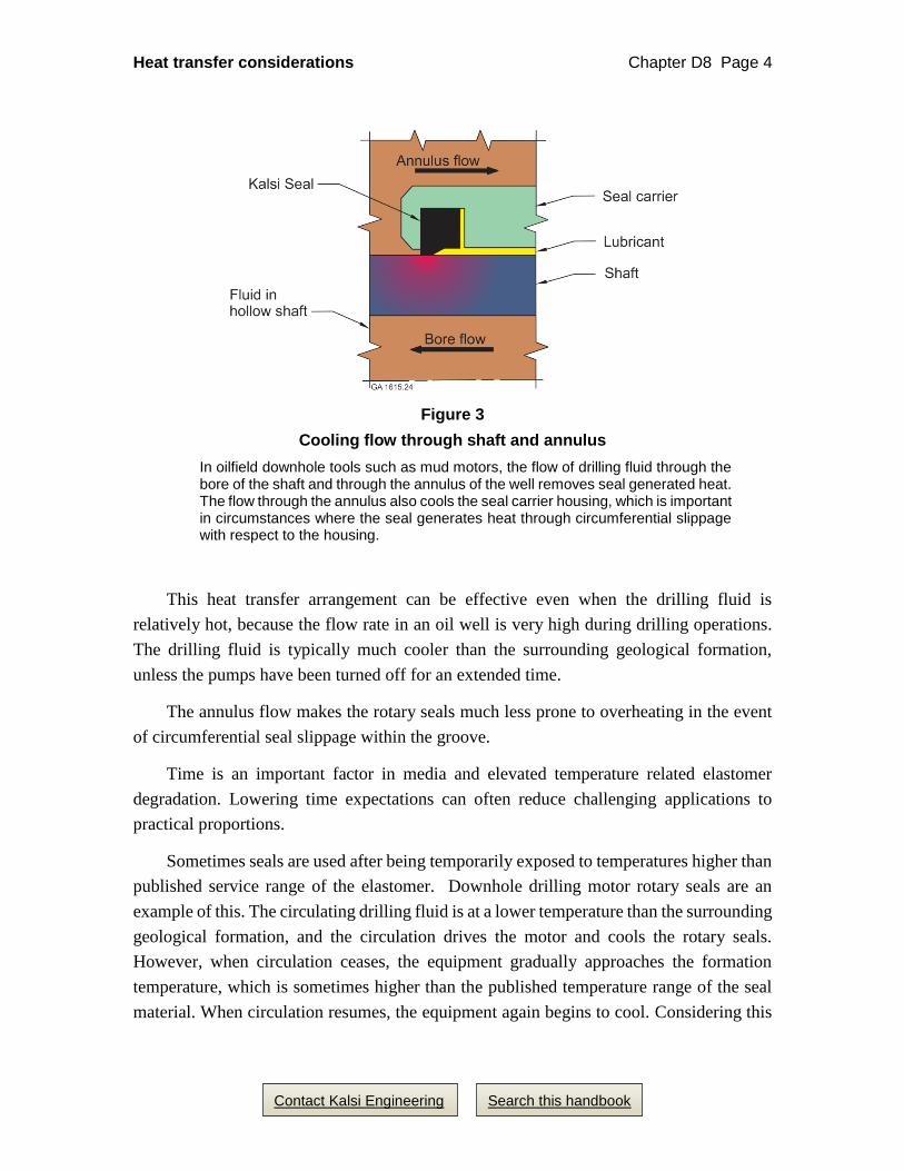
Oilfield downhole drilling tools
In well drilling, the drilling fluid circulates down through the drillstring, and returns
to the surface through the annulus of the well. One purpose of this circulation is to remove
cuttings from the wellbore; another is to cool the downhole tools. The bore flow removes
seal generated heat from the shaft, and the annulus flow removes seal generated heat from
the seal carrier (Figure 3).
Heat transfer considerations Chapter D8 Page 4
Contact Kalsi Engineering Search this handbook
Figure 3
Cooling flow through shaft and annulus
In oilfield downhole tools such as mud motors, the flow of drilling fluid through the bore of the shaft and through the annulus of the well removes seal generated heat. The flow through the annulus also cools the seal carrier housing, which is important in circumstances where the seal generates heat through circumferential slippage with respect to the housing.
This heat transfer arrangement can be effective even when the drilling fluid is
relatively hot, because the flow rate in an oil well is very high during drilling operations.
The drilling fluid is typically much cooler than the surrounding geological formation,
unless the pumps have been turned off for an extended time.
The annulus flow makes the rotary seals much less prone to overheating in the event
of circumferential seal slippage within the groove.
Time is an important factor in media and elevated temperature related elastomer
degradation. Lowering time expectations can often reduce challenging applications to
practical proportions.
Sometimes seals are used after being temporarily exposed to temperatures higher than
published service range of the elastomer. Downhole drilling motor rotary seals are an
example of this. The circulating drilling fluid is at a lower temperature than the surrounding
geological formation, and the circulation drives the motor and cools the rotary seals.
However, when circulation ceases, the equipment gradually approaches the formation
temperature, which is sometimes higher than the published temperature range of the seal
material. When circulation resumes, the equipment again begins to cool. Considering this
Heat transfer considerations Chapter D8 Page 5
Contact Kalsi Engineering Search this handbook
circumstance, it is important to size the width of the seal gland to accommodate the highest
anticipated temperature, even though the highest temperature may only last a short time.
Avoid the trap of specifying requirements for operating temperature and life that are
unrealistically high. Such requirements can inadvertently prevent the utilization of rotary
seal materials that may actually represent better overall performance and economic
compromises.
Figure 4
Increasing bore surface area
The larger bore diameter increases surface area, but has little impact on shaft strength. The additional surface area and thinner wall improves the cooling effect of fluid circulating through the shaft.
4. Shaft sleeves interrupt critical heat transfer to the bore flow
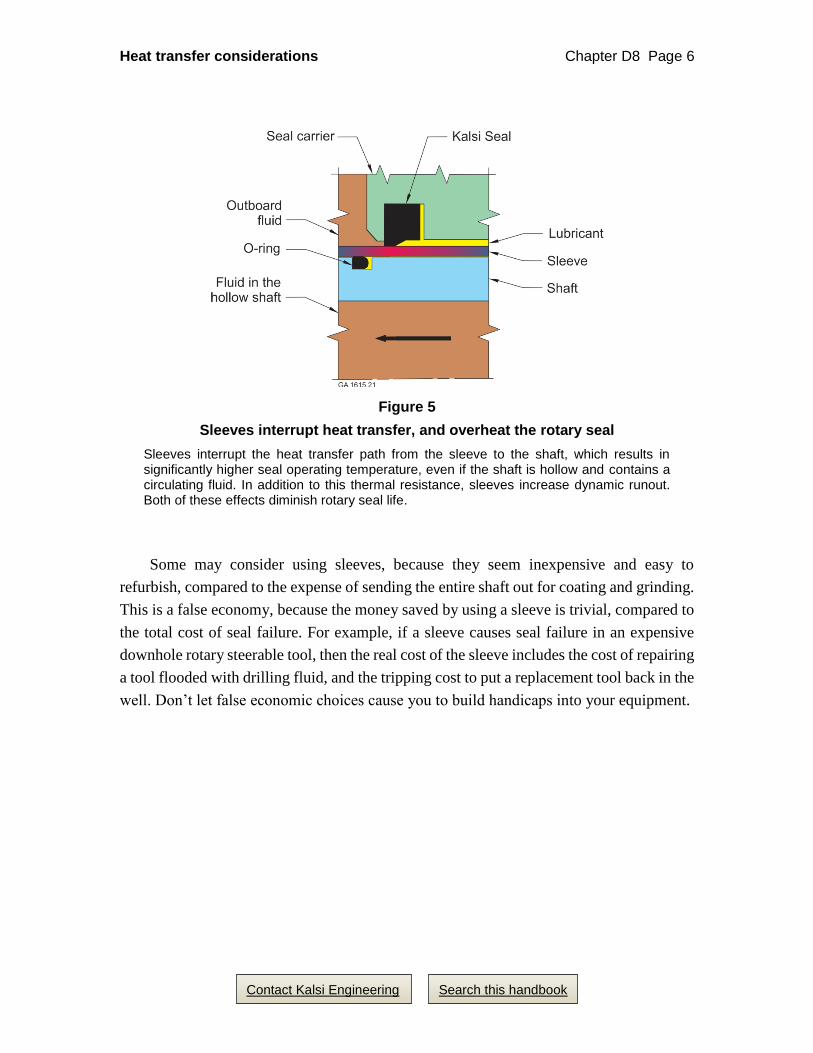
When possible, one should typically avoid shaft sleeves. Sleeves often cause rotary
seals to overheat, particularly with high pressure or high speed installations, because they
interrupt the heat transfer path to the shaft (Figure 5). Sleeves can also accelerate extrusion
damage, because they tend to increase runout and pressure breathing. Sleeves also typically
increase surface speed, which increases seal generated heat.
Kalsi Engineering typically advises against the use of shaft sleeves, because of the
critical necessity of good heat transfer in most sealing situations. Although several
comments below mention the use of sleeves, do not interpret these comments to mean that
Kalsi Engineering advocates the use of sleeves in your equipment. If you must use sleeves,
please consider using one of our newer rotary seal designs that provide reduced running
torque.
Heat transfer considerations Chapter D8 Page 6
Contact Kalsi Engineering Search this handbook
Figure 5
Sleeves interrupt heat transfer, and overheat the rotary seal
Sleeves interrupt the heat transfer path from the sleeve to the shaft, which results in significantly higher seal operating temperature, even if the shaft is hollow and contains a circulating fluid. In addition to this thermal resistance, sleeves increase dynamic runout. Both of these effects diminish rotary seal life.
Some may consider using sleeves, because they seem inexpensive and easy to
refurbish, compared to the expense of sending the entire shaft out for coating and grinding.
This is a false economy, because the money saved by using a sleeve is trivial, compared to
the total cost of seal failure. For example, if a sleeve causes seal failure in an expensive
downhole rotary steerable tool, then the real cost of the sleeve includes the cost of repairing
a tool flooded with drilling fluid, and the tripping cost to put a replacement tool back in the
well. Don’t let false economic choices cause you to build handicaps into your equipment.
Heat transfer considerations Chapter D8 Page 7
Contact Kalsi Engineering Search this handbook
Implications of sleeve thermal expansion
The seal generated heat concentrates in the sleeve, and does not transfer well to the
shaft or the seal carrier housing. This causes differential thermal expansion between the
sleeve and the shaft, and between the sleeve and the seal carrier housing. The result can be
significant, especially in large diameter equipment. Differential thermal expansion
between the sleeve and the shaft increases any clearance between the sleeve and the shaft,
which increases sleeve dynamic runout, and further reduces heat transfer between the seal
and the shaft. Differential thermal expansion between the sleeve and the seal carrier
housing reduces extrusion gap clearance, and may tend to bind any bearings installed
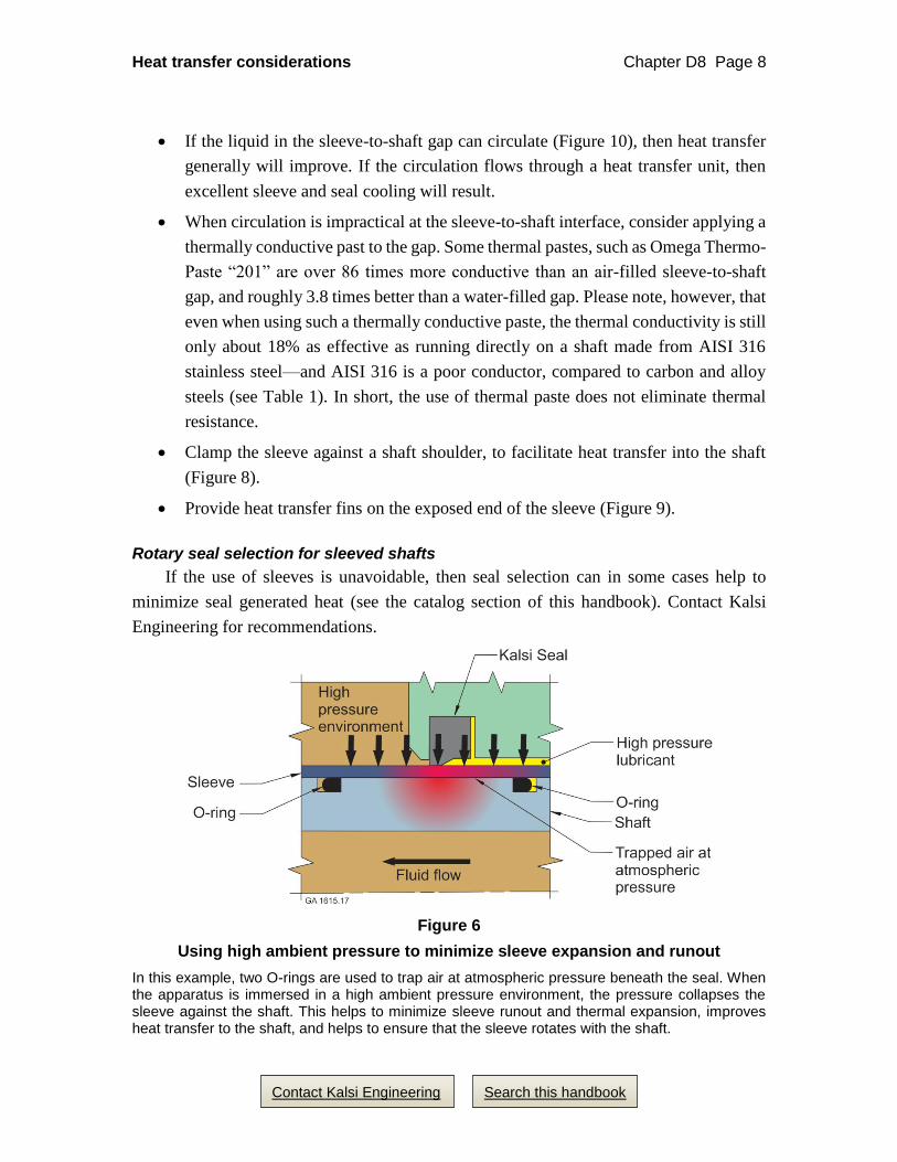
between the sleeve and the seal carrier housing. In high ambient pressure applications, it
may be possible to exploit the ambient pressure to minimize or eliminate differential
thermal expansion (Figure 6).
5. If sleeves are unavoidable
If shaft sleeves are unavoidable, the machine designer should focus on maximizing
heat transfer, minimizing runout, and ensuring that the sleeve rotates with the shaft. Here
are some considerations for maximizing heat transfer:
Allow the ends of the sleeve to project well past the rotary seals to expose plenty
of sleeve area for heat transfer.
Avoid very thin sleeves, because they restrict the axial flow of heat.
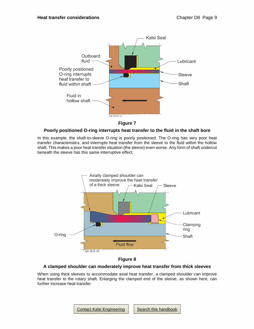
Do not position the sleeve O-ring directly beneath the running track of the rotary
seal, because the thermal conductivity of the O-ring is very poor (Figure 7).
Sleeve materials that have better thermal conductivity are generally considered to
be more desirable, provided the coefficient of thermal expansion of the sleeve
material, and the seal generated heat that concentrates in the sleeve, do not lead to
differential thermal expansion problems. Examples of potential problems are a
loose fit with the shaft, cracked hard coatings, and inadequate bearing and extrusion
gap clearance. Avoid stainless steel shaft sleeves when possible, because stainless
steel has poor thermal conductivity.
A close sleeve-to-shaft fit is better than a loose fit, in terms of maximizing heat
transfer to the shaft, and in terms of minimizing sleeve runout. A press fit is even
better, if the hard coating can tolerate it, but there will still be thermal resistance at
the press fit interface.
Providing a liquid in the sleeve-to-shaft gap is typically better than leaving an air
gap, because an air gap is a more effective insulator.
Heat transfer considerations Chapter D8 Page 8
Contact Kalsi Engineering Search this handbook
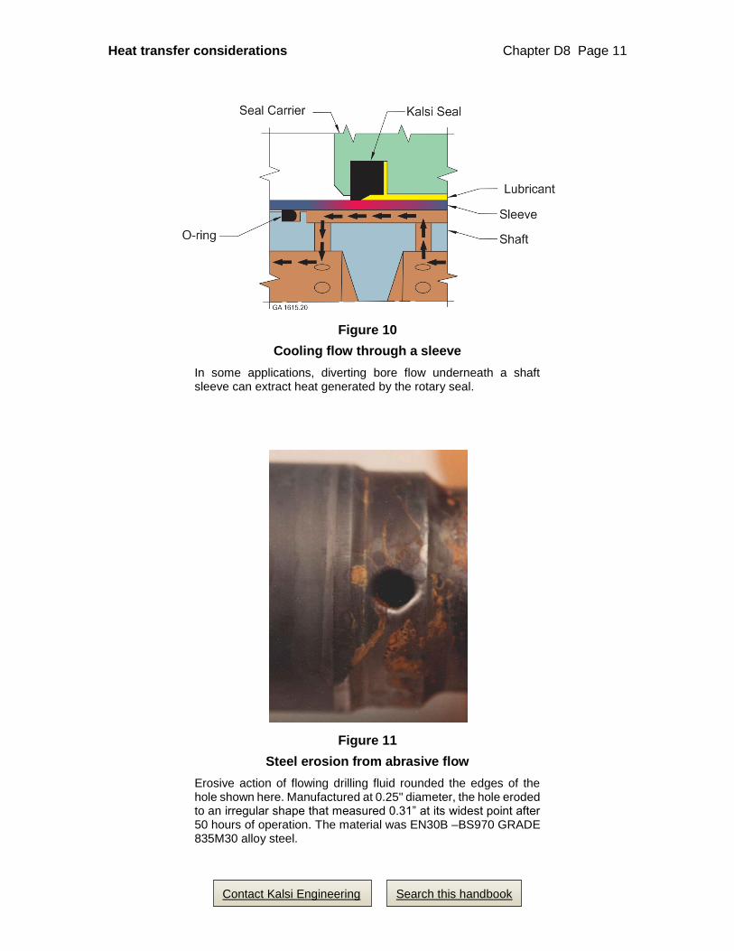
If the liquid in the sleeve-to-shaft gap can circulate (Figure 10), then heat transfer
generally will improve. If the circulation flows through a heat transfer unit, then
excellent sleeve and seal cooling will result.
When circulation is impractical at the sleeve-to-shaft interface, consider applying a
thermally conductive past to the gap. Some thermal pastes, such as Omega Thermo-
Paste “201” are over 86 times more conductive than an air-filled sleeve-to-shaft
gap, and roughly 3.8 times better than a water-filled gap. Please note, however, that
even when using such a thermally conductive paste, the thermal conductivity is still
only about 18% as effective as running directly on a shaft made from AISI 316
stainless steel—and AISI 316 is a poor conductor, compared to carbon and alloy
steels (see Table 1). In short, the use of thermal paste does not eliminate thermal
resistance.
Clamp the sleeve against a shaft shoulder, to facilitate heat transfer into the shaft
(Figure 8).
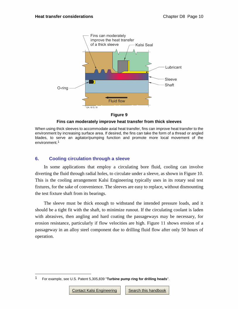
Provide heat transfer fins on the exposed end of the sleeve (Figure 9).
Rotary seal selection for sleeved shafts
If the use of sleeves is unavoidable, then seal selection can in some cases help to
minimize seal generated heat (see the catalog section of this handbook). Contact Kalsi
Engineering for recommendations.
Figure 6
Using high ambient pressure to minimize sleeve expansion and runout
In this example, two O-rings are used to trap air at atmospheric pressure beneath the seal. When the apparatus is immersed in a high ambient pressure environment, the pressure collapses the sleeve against the shaft. This helps to minimize sleeve runout and thermal expansion, improves heat transfer to the shaft, and helps to ensure that the sleeve rotates with the shaft.
Heat transfer considerations Chapter D8 Page 9
Contact Kalsi Engineering Search this handbook
Figure 7
Poorly positioned O-ring interrupts heat transfer to the fluid in the shaft bore
In this example, the shaft-to-sleeve O-ring is poorly positioned. The O-ring has very poor heat transfer characteristics, and interrupts heat transfer from the sleeve to the fluid within the hollow shaft. This makes a poor heat transfer situation (the sleeve) even worse. Any form of shaft undercut beneath the sleeve has this same interruptive effect.
Figure 8
A clamped shoulder can moderately improve heat transfer from thick sleeves
When using thick sleeves to accommodate axial heat transfer, a clamped shoulder can improve heat transfer to the rotary shaft. Enlarging the clamped end of the sleeve, as shown here, can further increase heat transfer.
Heat transfer considerations Chapter D8 Page 10
Contact Kalsi Engineering Search this handbook
Figure 9
Fins can moderately improve heat transfer from thick sleeves
When using thick sleeves to accommodate axial heat transfer, fins can improve heat transfer to the environment by increasing surface area. If desired, the fins can take the form of a thread or angled blades, to serve an agitator/pumping function and promote more local movement of the
environment.1
6. Cooling circulation through a sleeve
In some applications that employ a circulating bore fluid, cooling can involve
diverting the fluid through radial holes, to circulate under a sleeve, as shown in Figure 10.
This is the cooling arrangement Kalsi Engineering typically uses in its rotary seal test
fixtures, for the sake of convenience. The sleeves are easy to replace, without dismounting
the test fixture shaft from its bearings.
The sleeve must be thick enough to withstand the intended pressure loads, and it
should be a tight fit with the shaft, to minimize runout. If the circulating coolant is laden
with abrasives, then angling and hard coating the passageways may be necessary, for
erosion resistance, particularly if flow velocities are high. Figure 11 shows erosion of a
passageway in an alloy steel component due to drilling fluid flow after only 50 hours of
operation.
1 For example, see U.S. Patent 5,305,839 "Turbine pump ring for drilling heads".
Heat transfer considerations Chapter D8 Page 11
Contact Kalsi Engineering Search this handbook
Figure 10
Cooling flow through a sleeve
In some applications, diverting bore flow underneath a shaft sleeve can extract heat generated by the rotary seal.
Figure 11
Steel erosion from abrasive flow
Erosive action of flowing drilling fluid rounded the edges of the hole shown here. Manufactured at 0.25" diameter, the hole eroded to an irregular shape that measured 0.31” at its widest point after 50 hours of operation. The material was EN30B –BS970 GRADE 835M30 alloy steel.
Heat transfer considerations Chapter D8 Page 12
Contact Kalsi Engineering Search this handbook
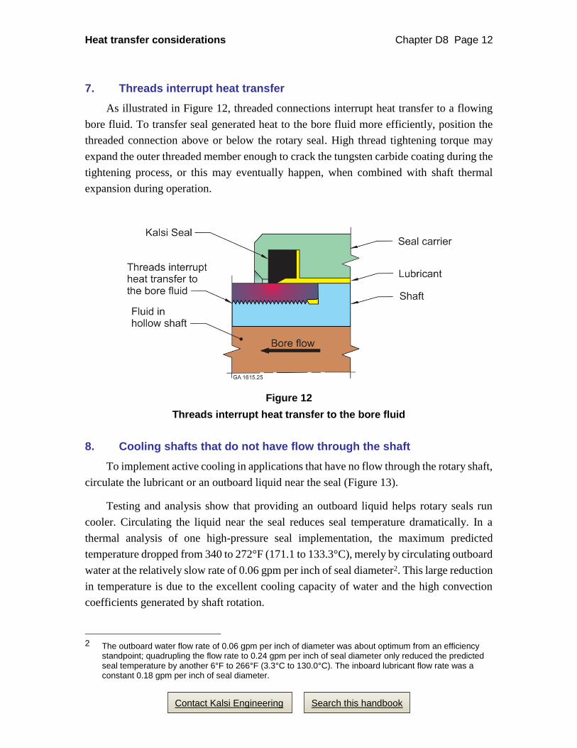
7. Threads interrupt heat transfer
As illustrated in Figure 12, threaded connections interrupt heat transfer to a flowing
bore fluid. To transfer seal generated heat to the bore fluid more efficiently, position the
threaded connection above or below the rotary seal. High thread tightening torque may
expand the outer threaded member enough to crack the tungsten carbide coating during the
tightening process, or this may eventually happen, when combined with shaft thermal
expansion during operation.
Figure 12
Threads interrupt heat transfer to the bore fluid
8. Cooling shafts that do not have flow through the shaft
To implement active cooling in applications that have no flow through the rotary shaft,
circulate the lubricant or an outboard liquid near the seal (Figure 13).
Testing and analysis show that providing an outboard liquid helps rotary seals run
cooler. Circulating the liquid near the seal reduces seal temperature dramatically. In a
thermal analysis of one high-pressure seal implementation, the maximum predicted
temperature dropped from 340 to 272°F (171.1 to 133.3°C), merely by circulating outboard
water at the relatively slow rate of 0.06 gpm per inch of seal diameter2. This large reduction
in temperature is due to the excellent cooling capacity of water and the high convection
coefficients generated by shaft rotation.
2 The outboard water flow rate of 0.06 gpm per inch of diameter was about optimum from an efficiency
standpoint; quadrupling the flow rate to 0.24 gpm per inch of seal diameter only reduced the predicted seal temperature by another 6°F to 266°F (3.3°C to 130.0°C). The inboard lubricant flow rate was a constant 0.18 gpm per inch of seal diameter.

Heat transfer considerations Chapter D8 Page 13
Contact Kalsi Engineering Search this handbook
Figure 13
Circulation of the lubricant and/or an outboard fluid
Seal generated heat can be extracted by circulation of the lubricant and an outboard liquid, as shown here. The use of one or both of these circulation methods is recommended for oilfield rotary control devices (RCD’s).
Heat transfer considerations Chapter D8 Page 14
Contact Kalsi Engineering Search this handbook
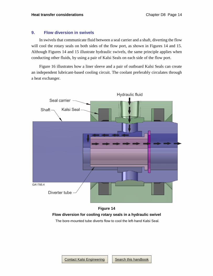
9. Flow diversion in swivels
In swivels that communicate fluid between a seal carrier and a shaft, diverting the flow
will cool the rotary seals on both sides of the flow port, as shown in Figures 14 and 15.
Although Figures 14 and 15 illustrate hydraulic swivels, the same principle applies when
conducting other fluids, by using a pair of Kalsi Seals on each side of the flow port.
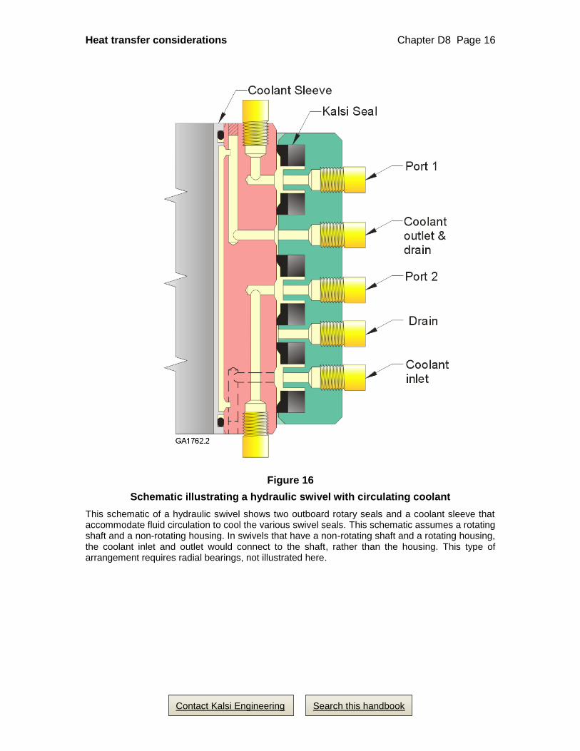
Figure 16 illustrates how a liner sleeve and a pair of outboard Kalsi Seals can create
an independent lubricant-based cooling circuit. The coolant preferably circulates through
a heat exchanger.
Figure 14
Flow diversion for cooling rotary seals in a hydraulic swivel
The bore-mounted tube diverts flow to cool the left-hand Kalsi Seal.
Heat transfer considerations Chapter D8 Page 15
Contact Kalsi Engineering Search this handbook
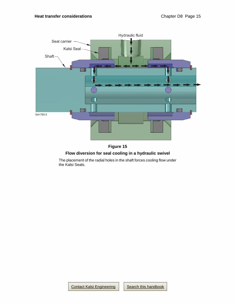
Figure 15
Flow diversion for seal cooling in a hydraulic swivel
The placement of the radial holes in the shaft forces cooling flow under the Kalsi Seals.
Heat transfer considerations Chapter D8 Page 16
Contact Kalsi Engineering Search this handbook
Figure 16
Schematic illustrating a hydraulic swivel with circulating coolant
This schematic of a hydraulic swivel shows two outboard rotary seals and a coolant sleeve that accommodate fluid circulation to cool the various swivel seals. This schematic assumes a rotating shaft and a non-rotating housing. In swivels that have a non-rotating shaft and a rotating housing, the coolant inlet and outlet would connect to the shaft, rather than the housing. This type of arrangement requires radial bearings, not illustrated here.

Heat transfer considerations Chapter D8 Page 17
Contact Kalsi Engineering Search this handbook
10. Shaft driven cooling circulation
A shaft driven ring with angled holes can serve as a fan or pump
Lack of air movement is an impediment to good heat transfer. Air circulation around
the equipment can effect a dramatic reduction in temperature. In pumps and other surface
equipment, it may be possible to arrange for a simple shaft-driven fan that cools the seal
housing via forced air circulation (Figure 17). The fan in Figure 17 is an economical shaft-
driven metal ring with angled, drilled or milled holes that cause significant airflow. Even
though rotating equipment requires appropriate rotating shaft guards, the fan design itself
provides an additional level of personnel protection by virtue of a closed rim design, which
is less prone to snagging than open rim designs.
The same basic type of component could be used to circulate lubricant axially through
rolling element bearings, provided that a suitable return flow passage is provided. Such
circulation helps to cool the shaft, which in turn helps to cool the rotary seals.
Figure 17
Shaft driven cooling fan
Angled drilled holes provide the basis for this simple shaft-driven air circulation fan, used on an oilfield cement pump seal cartridge to help cool the rotary seals by cooling the seal housing. The same type of rotating component could be used to circulate lubricant through rolling element bearings, if a return circulation path is provided. Such circulation helps to extract heat from the shaft, which reduces the temperature of the rotary seals.
Heat transfer considerations Chapter D8 Page 18
Contact Kalsi Engineering Search this handbook
Static or rotating thread forms to promote lubricant movement
Figure 9 describes the use of shaft or sleeve mounted threads or vanes to provide fluid
movement for rotary seal cooling purposes. For more details on this cooling method, see
expired U.S. Patent 5,305,8393.
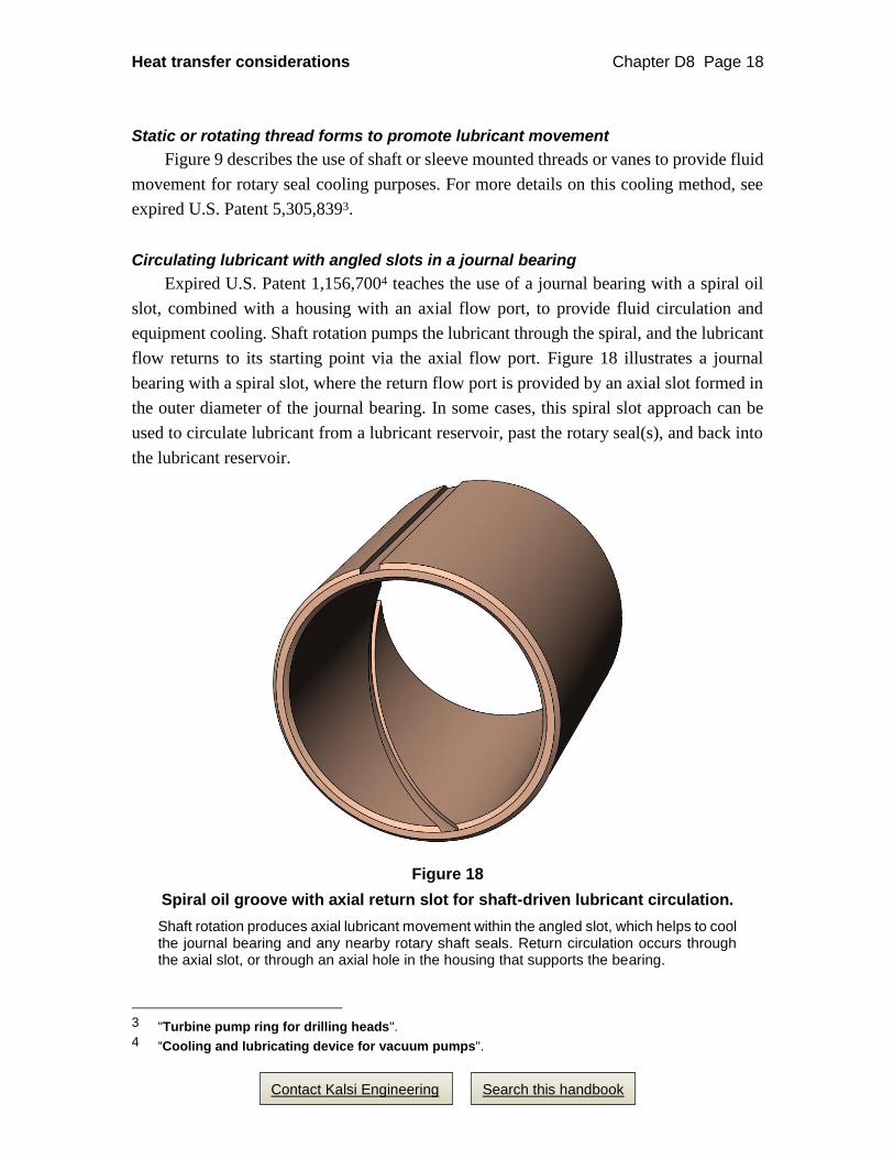
Circulating lubricant with angled slots in a journal bearing
Expired U.S. Patent 1,156,7004 teaches the use of a journal bearing with a spiral oil
slot, combined with a housing with an axial flow port, to provide fluid circulation and
equipment cooling. Shaft rotation pumps the lubricant through the spiral, and the lubricant
flow returns to its starting point via the axial flow port. Figure 18 illustrates a journal
bearing with a spiral slot, where the return flow port is provided by an axial slot formed in
the outer diameter of the journal bearing. In some cases, this spiral slot approach can be
used to circulate lubricant from a lubricant reservoir, past the rotary seal(s), and back into
the lubricant reservoir.
Figure 18
Spiral oil groove with axial return slot for shaft-driven lubricant circulation.
Shaft rotation produces axial lubricant movement within the angled slot, which helps to cool the journal bearing and any nearby rotary shaft seals. Return circulation occurs through the axial slot, or through an axial hole in the housing that supports the bearing.
3 "Turbine pump ring for drilling heads". 4 “Cooling and lubricating device for vacuum pumps".
Heat transfer considerations Chapter D8 Page 19
Contact Kalsi Engineering Search this handbook
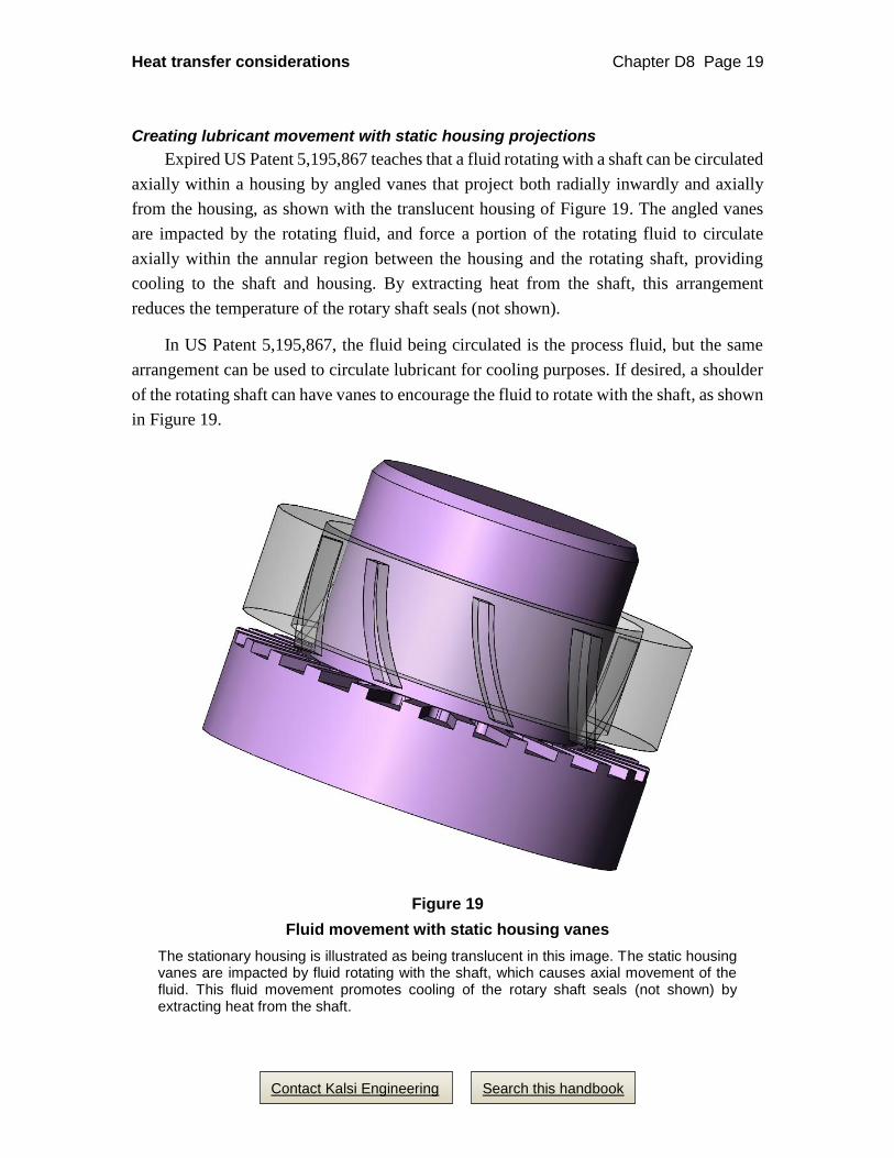
Creating lubricant movement with static housing projections
Expired US Patent 5,195,867 teaches that a fluid rotating with a shaft can be circulated
axially within a housing by angled vanes that project both radially inwardly and axially
from the housing, as shown with the translucent housing of Figure 19. The angled vanes
are impacted by the rotating fluid, and force a portion of the rotating fluid to circulate
axially within the annular region between the housing and the rotating shaft, providing
cooling to the shaft and housing. By extracting heat from the shaft, this arrangement
reduces the temperature of the rotary shaft seals (not shown).
In US Patent 5,195,867, the fluid being circulated is the process fluid, but the same
arrangement can be used to circulate lubricant for cooling purposes. If desired, a shoulder
of the rotating shaft can have vanes to encourage the fluid to rotate with the shaft, as shown
in Figure 19.
Figure 19
Fluid movement with static housing vanes
The stationary housing is illustrated as being translucent in this image. The static housing vanes are impacted by fluid rotating with the shaft, which causes axial movement of the fluid. This fluid movement promotes cooling of the rotary shaft seals (not shown) by extracting heat from the shaft.

Heat transfer considerations Chapter D8 Page 20
Search this handbook Contact Kalsi Engineering
11. Seal spacing to minimize the overlap of heat zones
The cumulative temperature effect of having two or more rotary seals positioned
close together is important to consider. As a general rule of thumb, solid cross section
Kalsi Seals should be no closer than about 1.00 to 1.25” (25.4 to 31.75 mm) apart, as
measured from the centers of the respective seal footprints, in order to minimize the
overlap of their respective heat zones (Figure 20).
Figure 20
Space seals to minimize heat zone overlap
As a general rule of thumb, to minimize heat zone overlap, solid cross section Kalsi Seals should be no closer than about 1.00 to 1.25” (25.4 to 31.75 mm) apart, as measured from the centers of the seal footprints. This recommendation is based on finite element analysis (FEA) of the heat transfer characteristics of typical Kalsi Engineering seal test fixtures. For best guidance on this topic, use FEA to evaluate the heat transfer conditions that are applicable to your equipment.
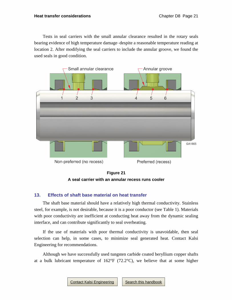
12. Seal carrier-to-shaft clearance influences seal temperature
An annular groove can improve heat transfer. Kalsi Engineering tests pairs of rotary
seals, as depicted schematically in Figure 21. The seal carrier on the left hand side of
Figure 21 has a small annular clearance in the region between the seals. When Kalsi
Engineering performed rotary seal tests in such seal carriers, without using lubricant
circulation, the temperature at location 2 was much less than the temperatures near the
seals at locations 1 and 3. Temperature differences have been as much as 200°F.
The seal carrier on the right hand side of Figure 21 has an annular clearance groove
between the seals. When Kalsi Engineering performed rotary seal tests in such seal
carriers without using lubricant circulation, the temperatures at locations 4 and 6 were
considerably lower than those at locations 1 and 3, and the temperature gradient between
location 5 and locations 4 and 6 was only a few degrees.
Heat transfer considerations Chapter D8 Page 21
Contact Kalsi Engineering Search this handbook
Tests in seal carriers with the small annular clearance resulted in the rotary seals
bearing evidence of high temperature damage–despite a reasonable temperature reading at
location 2. After modifying the seal carriers to include the annular groove, we found the
used seals in good condition.
Figure 21
A seal carrier with an annular recess runs cooler
13. Effects of shaft base material on heat transfer
The shaft base material should have a relatively high thermal conductivity. Stainless
steel, for example, is not desirable, because it is a poor conductor (see Table 1). Materials
with poor conductivity are inefficient at conducting heat away from the dynamic sealing
interface, and can contribute significantly to seal overheating.
If the use of materials with poor thermal conductivity is unavoidable, then seal
selection can help, in some cases, to minimize seal generated heat. Contact Kalsi
Engineering for recommendations.
Although we have successfully used tungsten carbide coated beryllium copper shafts
at a bulk lubricant temperature of 162°F (72.2°C), we believe that at some higher
Heat transfer considerations Chapter D8 Page 22
Contact Kalsi Engineering Search this handbook
temperature, the differential thermal expansion between the shaft and the coating may
result in cracking.
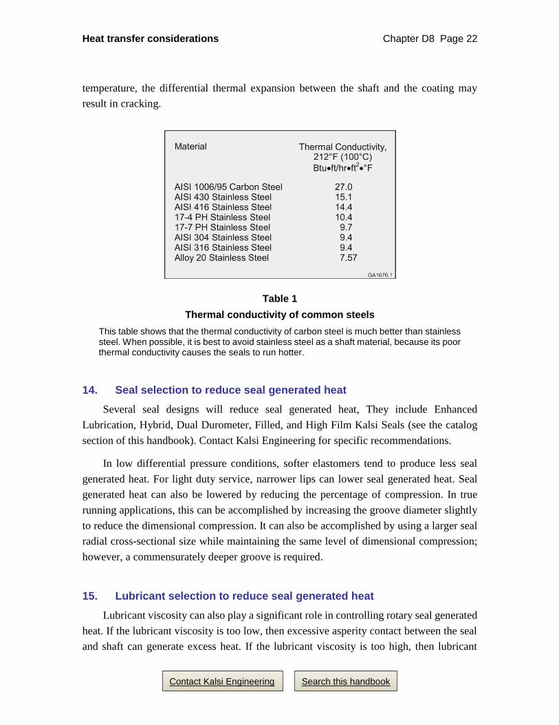
Table 1
Thermal conductivity of common steels
This table shows that the thermal conductivity of carbon steel is much better than stainless steel. When possible, it is best to avoid stainless steel as a shaft material, because its poor thermal conductivity causes the seals to run hotter.
14. Seal selection to reduce seal generated heat
Several seal designs will reduce seal generated heat, They include Enhanced
Lubrication, Hybrid, Dual Durometer, Filled, and High Film Kalsi Seals (see the catalog
section of this handbook). Contact Kalsi Engineering for specific recommendations.
In low differential pressure conditions, softer elastomers tend to produce less seal
generated heat. For light duty service, narrower lips can lower seal generated heat. Seal
generated heat can also be lowered by reducing the percentage of compression. In true
running applications, this can be accomplished by increasing the groove diameter slightly
to reduce the dimensional compression. It can also be accomplished by using a larger seal
radial cross-sectional size while maintaining the same level of dimensional compression;
however, a commensurately deeper groove is required.
15. Lubricant selection to reduce seal generated heat
Lubricant viscosity can also play a significant role in controlling rotary seal generated
heat. If the lubricant viscosity is too low, then excessive asperity contact between the seal
and shaft can generate excess heat. If the lubricant viscosity is too high, then lubricant
Heat transfer considerations Chapter D8 Page 23
Contact Kalsi Engineering Search this handbook
shearing action can generate excess heat. Due to the unique heat transfer aspects of each
application, optimum viscosity can only be determined through testing in the actual
hardware under realistic conditions.
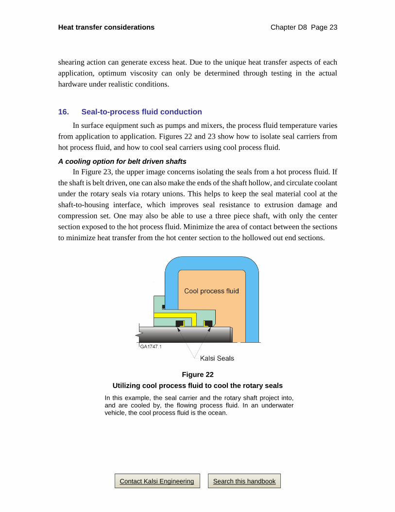
16. Seal-to-process fluid conduction
In surface equipment such as pumps and mixers, the process fluid temperature varies
from application to application. Figures 22 and 23 show how to isolate seal carriers from
hot process fluid, and how to cool seal carriers using cool process fluid.
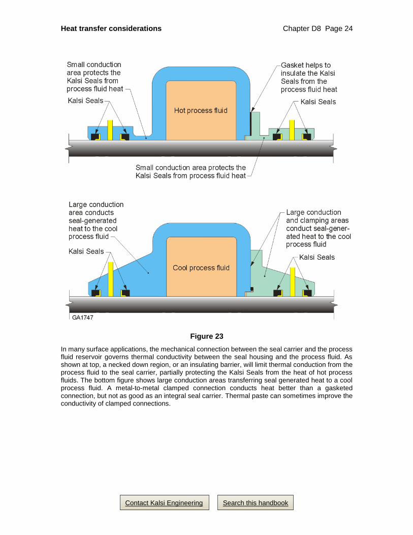
A cooling option for belt driven shafts
In Figure 23, the upper image concerns isolating the seals from a hot process fluid. If
the shaft is belt driven, one can also make the ends of the shaft hollow, and circulate coolant
under the rotary seals via rotary unions. This helps to keep the seal material cool at the
shaft-to-housing interface, which improves seal resistance to extrusion damage and
compression set. One may also be able to use a three piece shaft, with only the center
section exposed to the hot process fluid. Minimize the area of contact between the sections
to minimize heat transfer from the hot center section to the hollowed out end sections.
Figure 22
Utilizing cool process fluid to cool the rotary seals
In this example, the seal carrier and the rotary shaft project into, and are cooled by, the flowing process fluid. In an underwater vehicle, the cool process fluid is the ocean.
Heat transfer considerations Chapter D8 Page 24
Contact Kalsi Engineering Search this handbook
Figure 23
In many surface applications, the mechanical connection between the seal carrier and the process fluid reservoir governs thermal conductivity between the seal housing and the process fluid. As shown at top, a necked down region, or an insulating barrier, will limit thermal conduction from the process fluid to the seal carrier, partially protecting the Kalsi Seals from the heat of hot process fluids. The bottom figure shows large conduction areas transferring seal generated heat to a cool process fluid. A metal-to-metal clamped connection conducts heat better than a gasketed connection, but not as good as an integral seal carrier. Thermal paste can sometimes improve the conductivity of clamped connections.