Embed Size (px)
Citation preview
GTWHEAT RECOVERY SILENCERS FOR GAS TURBINES
Size Range: 5 lbs/sec to 60 lbs/sec exhaust flow 90 HP through 6,000 HP - larger sizes available depending on application
Development: With development of the small gas turbine for industrial and commercial use, Maxim recognized the need for an exhaust heat recovery package that would complement the simplicity, responsiveness, compactness, adaptability and other advantages of this engine.
After three years of development work and five years evaluation in the field, the second generation GTW emerged as a highly dependable and economical gas turbine heat recovery unit. Functionally, the unit is a watertube/waterwall design which accounts for the responsiveness and low weight. This design eliminates the need for an external gas-tight casing.
Construction: Each heat recovery section is an assembly of individual modules. This building block approach allows every unit to be tailored to the requirements of a particular installation or to the limits of the heat source.
If the system heat requirement is variable, the GTW can be equipped with an integral internal exhaust gas bypass. This consists of a pneumatically actuated modulating valve which diverts excess hot gas through an insulated duct adjacent to the water tube section.In many instances, silencing is of prime importance. The GTW will reduce typical turbine exhaust noise by approximately 5 dBA which in many cases will satisfy the noise criteria. If additional silencing is required, the GTW can be supplied with a parallel panel exhaust silencer to meet the most demanding criteria.
Although assembled from standard components, each GTW is engineered to meet the needs of a particular installation. It is delivered as a complete package with thermal insulation, controls, accessories and a base.
Accessories: Already established and proven in hundreds of installations, Maxim heat recovery equipment includes both water and air-cooled load control condensers, back pressure valves, excess steam valves, condensate return systems, pump control panels, and steam separators.
MAXIM SILENCERS, INC. Rev. 12.01.08
Silencing + Quality Steam Generation or Liquid Heating
AP
PLI
CA
TIO
NS:
CO
DE
CO
MP
LIA
NC
E The Maxim GTW heat recovery unit is designed and fabricated in compliance with Section VIII or Section I, Division I, ASME Code.
• Hospitals• Schools• Office buildings• Shopping centers• Offshore platforms• Oil & Gas production facilities• Industrial plants• Marine
MAXIM SILENCERS, INC. Rev. 12.01.08
GTWFLOW DIAGRAMO
PE
RA
TIO
N
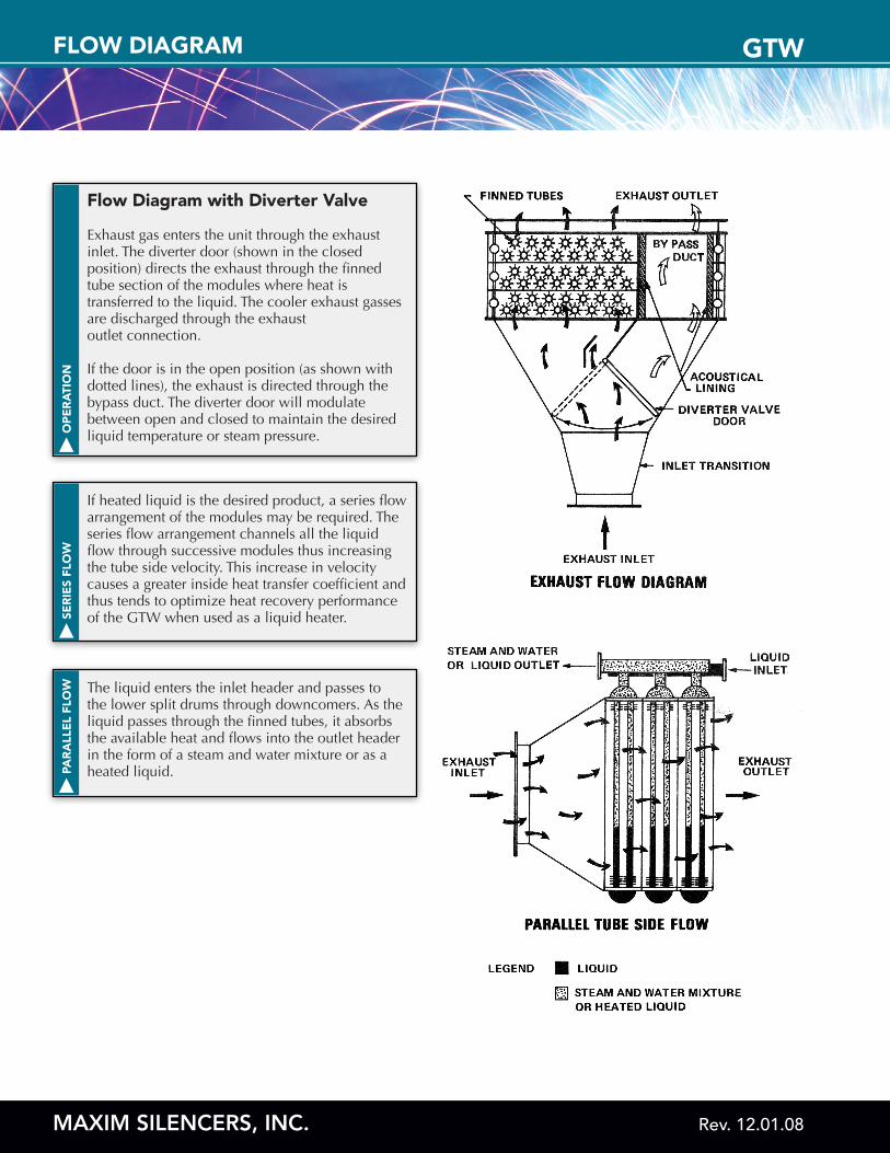
Flow Diagram with Diverter Valve
Exhaust gas enters the unit through the exhaust inlet. The diverter door (shown in the closed position) directs the exhaust through the finned tube section of the modules where heat is transferred to the liquid. The cooler exhaust gasses are discharged through the exhaust outlet connection.
If the door is in the open position (as shown with dotted lines), the exhaust is directed through the bypass duct. The diverter door will modulate between open and closed to maintain the desired liquid temperature or steam pressure.
SER
IES
FLO
W
If heated liquid is the desired product, a series flow arrangement of the modules may be required. The series flow arrangement channels all the liquid flow through successive modules thus increasing the tube side velocity. This increase in velocity causes a greater inside heat transfer coefficient and thus tends to optimize heat recovery performance of the GTW when used as a liquid heater.
PAR
ALL
EL
FLO
W The liquid enters the inlet header and passes to the lower split drums through downcomers. As the liquid passes through the finned tubes, it absorbs the available heat and flows into the outlet header in the form of a steam and water mixture or as a heated liquid.
MAXIM SILENCERS, INC. Rev. 12.01.08
GTWNOMENCLATURE
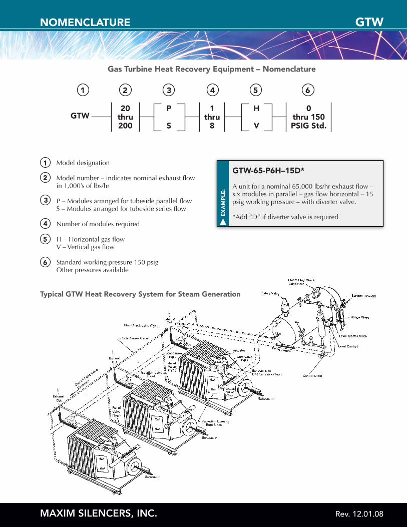
Gas Turbine Heat Recovery Equipment – Nomenclature
1
GTW20
thru200
P
S
1thru
8
H
V
0thru 150PSIG Std.
2 3 4 5 6
Model designation
Model number – indicates nominal exhaust flow in 1,000’s of lbs/hr
P – Modules arranged for tubeside parallel flow S – Modules arranged for tubeside series flow
Number of modules required
H – Horizontal gas flow V – Vertical gas flow
Standard working pressure 150 psig Other pressures available
1
2
3
4
5
6
EX
AM
PLE
:
GTW-65-P6H–15D*
A unit for a nominal 65,000 lbs/hr exhaust flow – six modules in parallel – gas flow horizontal – 15 psig working pressure – with diverter valve.
*Add “D” if diverter valve is required
Typical GTW Heat Recovery System for Steam Generation


![Vol 8 Gtw Final[1]](https://img.dokumen.tips/doc/110x75/54841dfd5806b5c7588b45d7/vol-8-gtw-final1.jpg)


